Embed Size (px)
Citation preview
DESIGN
®
www.pic-design.comInteractive catalog ■ CAD ■ e-commerce
Phone: 800-243-6125 ■ FAX: 203-758-8271E-Mail: [email protected] 7-1
DESIGN
RECISIONNDUSTRIALOMPONENTS
R
R
& COUPLINGSCLUTCHES, BRAKES
Bellows CouplingsZero Adjustable CouplingsFlexible CouplingsMiniature Oldham CouplingsWafer Oldham CouplingsUniversal Lateral CouplingsMulti-Jaw CouplingsPrecision Universal Joint CouplingsMolded Universal Joint CouplingsPrecision Sleeve CouplingsFlexible Zero Backlash CouplingsSpider Coupling
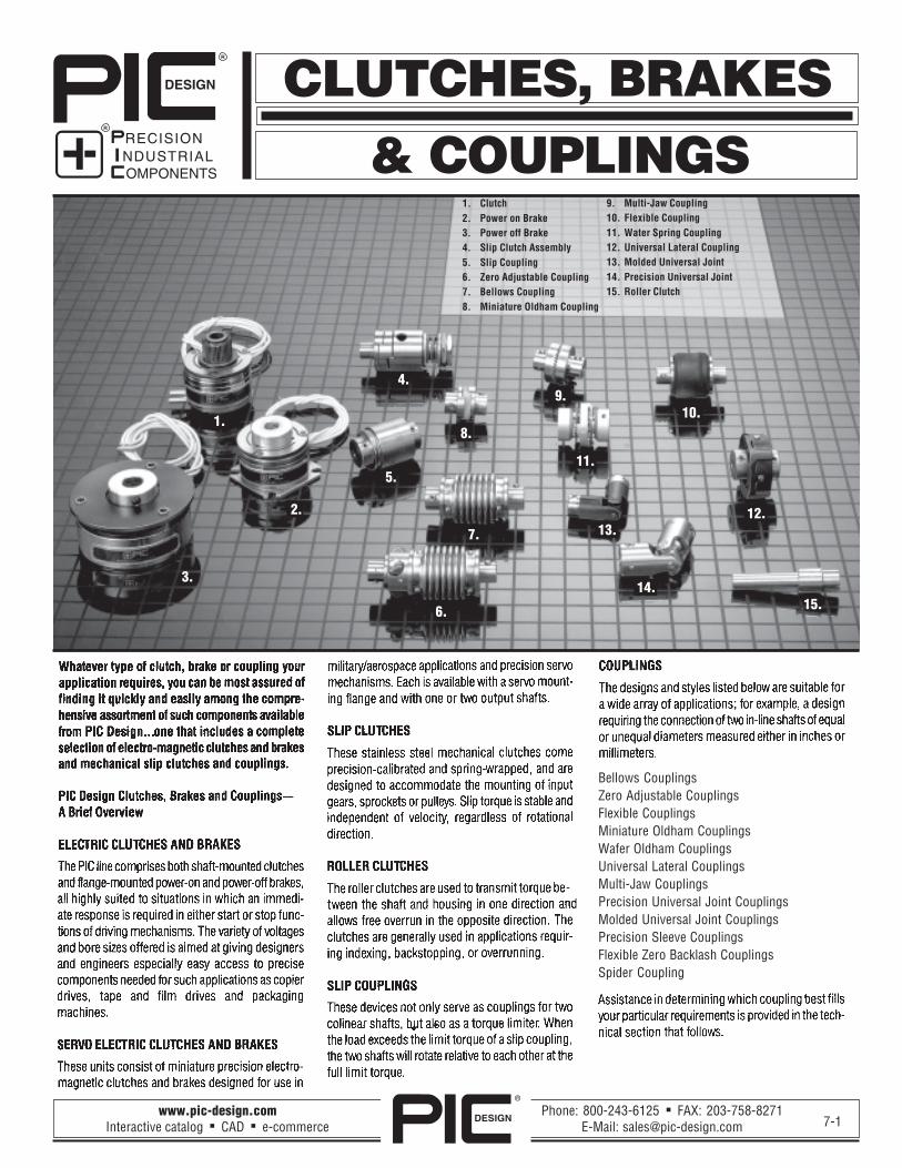
1. Clutch2. Power on Brake3. Power off Brake4. Slip Clutch Assembly5. Slip Coupling6. Zero Adjustable Coupling7. Bellows Coupling8. Miniature Oldham Coupling
9. Multi-Jaw Coupling10. Flexible Coupling11. Water Spring Coupling12. Universal Lateral Coupling13. Molded Universal Joint14. Precision Universal Joint15. Roller Clutch
4.
3.
5.
6.
2.
11.
13.
14.
12.
10.9.
7.
8.1.
15.
DESIGN
®
www.pic-design.comInteractive catalog ■ CAD ■ e-commerce
Phone: 800-243-6125 ■ FAX: 203-758-8271E-Mail: [email protected]
TECHNICAL SECTIONIndustrial Clutches and Brakes
7-2
Bellows CouplingsThe ideal solution where shafts are angularlly andlaterally misaligned. They feature a stainless steel hubpinned to a stainless steel bellows.
Zero Adjustable CouplingsGet the same characteristics as on the bellows typecoupling, except these couplings have an adjustablehub for zeroing synchros and other similar devices.
Precision Sleeve CouplingsUse them when coupling shafts of similar ordissimilar diameters. This allows you tocouple inch to inch, millimeter to millimeter,and inch to millimeter shafts.
Flexible Zero Backlash CouplingsWork well in high accuracy systems. Stainlesssteel or aluminum one-piece construction withhigh torsional stiffness, constant velocity, andvery low wind up.
Flexible K CouplingsAn excellent choice for use in abrasive dustenvironments and where maximum flexibilityis required. The hubs are zinc plated; thebodies are polyurethane.
Spider CouplingsThese provide high torque transmissionwithout backlash or vibration due to the use ofa chemically resistant and electrical isolatingelastomer insert.
Shaft ExtensionsUsed to add an additional inch of shaft lengthor facilitate a change from special to standardshaft diameter. — See Section 6.
Flexible CouplingsThese will isolate vibration, absorb shockloads and electrically insulate. They feature amolded neoprene body connected tostainless steel hubs.
Miniature Oldham CouplingsA choice of center block of oil impregnatedbronze or nylon (eliminates metal-to-metalcontact from taking place) between the hubs.Use these couplings in high-torqueapplications.
Wafer Spring CouplingsThe choice for your highest torque applica-tions and where there is up to 8o of angularand .03 inches of lateral misalignment.
Universal Lateral CouplingsNot only will these couplings provideelectrical insulation, but they can handle upto 10o angular and .05 inches of lateralmisalignment.
Multi-Jaw CouplingsInterlocking teeth permit precision coupling/decoupling with limited transmission errorbetween two stainless steel hubs.
Universal Joint CouplingsWorking angles up to 30o are no problemwhen you use these coupling. Standard ineither Stainless Steel or Delrin.
Couplings
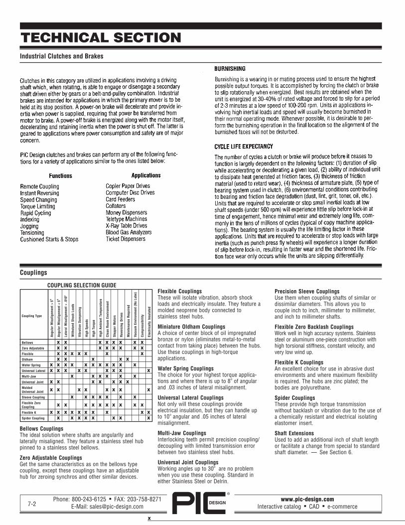
COUPLING SELECTION GUIDE
Bellows X X X X X X X XZero Adjustable X X X X X X X XFlexible X X X X X X XOldham X X X X XWafer Spring X X X X X X X X X X XUniversal Lateral X X X X X X X X XMulti-Jaw X X X X X XUniversal Joint X X X X X X XMoldedUniversal Joint X X X X X X X X
Sleeve Coupling X X X X X X XFlexible ZeroCoupling X X X X X X X X X X
Flexible K X X X X X X X X X XSpider Coupling X X X X X X X X
Coupling Type
Angu
lar
Mis
alig
nmen
t >
5o
Angu
lar
Mis
alig
nmen
t <
5o
Late
ral
Mis
alig
nmen
t >
.010
"
With
stan
d Sh
ock
Load
s
Vibr
atio
n D
ampe
ning
Hig
h Sp
eeds
Hig
h To
rque
Hig
h Am
bien
t Tem
pera
ture
Clea
n R
oom
Env
iron
men
t
Step
per
Mot
ors
Rev
ersi
ng D
rive
s
Mai
nten
ance
Req
uire
d
Vacu
um E
nvir
onm
ent (
No
Lube
)
Com
pres
sibi
lity
Elec
tric
ally
Ins
ulat
ed
X
DESIGN
®
www.pic-design.comInteractive catalog ■ CAD ■ e-commerce
Phone: 800-243-6125 ■ FAX: 203-758-8271E-Mail: [email protected] 7-3
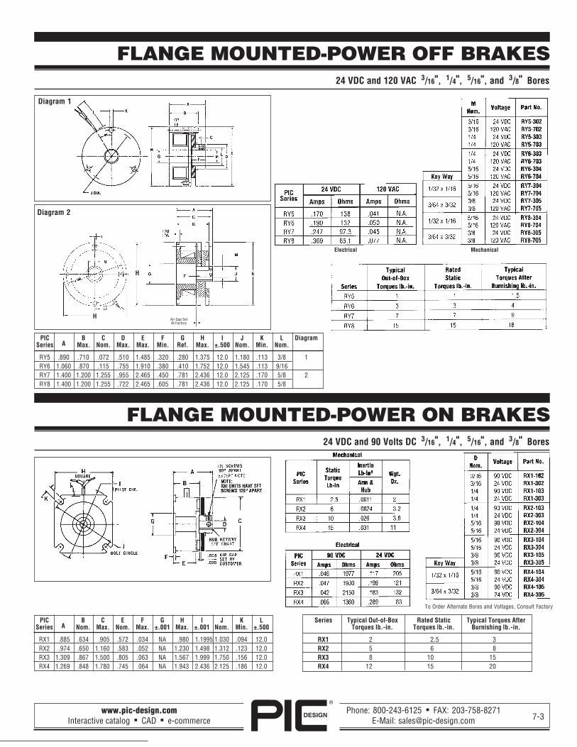
FLANGE MOUNTED-POWER OFF BRAKES24 VDC and 120 VAC 3/16", 1/4", 5/16", and 3/8" Bores
FLANGE MOUNTED-POWER ON BRAKES24 VDC and 90 Volts DC 3/16", 1/4", 5/16", and 3/8" Bores
To Order Alternate Bores and Voltages, Consult Factory
Diagram 1
PICA
B C D E F G H I J K L DiagramSeries Max. Nom. Max. Max. Min. Ref. Max. ±.500 Nom. Min. Nom.
RY5 .890 .710 .072 .510 1.485 .320 .280 1.375 12.0 1.180 .113 3/8 1RY6 1.060 .870 .115 .755 1.910 .380 .410 1.752 12.0 1.545 .113 9/16RY7 1.400 1.200 1.255 .955 2.465 .450 .781 2.436 12.0 2.125 .170 5/8 2RY8 1.400 1.200 1.255 .722 2.465 .605 .781 2.436 12.0 2.125 .170 5/8
Diagram 2
Mechanical
H
H
Air Gap SetAt Factory
Electrical
PICA
B C E F G H I J K LSeries Nom. Max. Nom. Max. ±.001 Max. ±.001 Nom. Min. ±.500
RX1 .885 .634 .905 .572 .034 NA .980 1.1995 1.030 .094 12.0RX2 .974 .650 1.160 .583 .052 NA 1.230 1.498 1.312 .123 12.0RX3 1.309 .867 1.500 .805 .063 NA 1.567 1.999 1.750 .156 12.0RX4 1.269 .848 1.780 .745 .064 NA 1.943 2.436 2.125 .186 12.0
Series Typical Out-of-Box Rated Static Typical Torques AfterTorques lb.-in. Torques lb.-in. Burnishing lb.-in.
RX1 2 2.5 3RX2 5 6 8RX3 8 10 15RX4 12 15 20
DESIGN
®
www.pic-design.comInteractive catalog ■ CAD ■ e-commerce
Phone: 800-243-6125 ■ FAX: 203-758-8271E-Mail: [email protected]
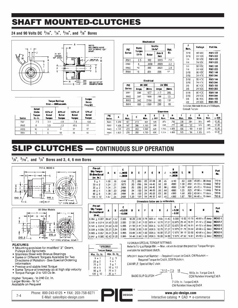
SHAFT MOUNTED-CLUTCHES24 and 90 Volts DC 3/16", 1/4", 5/16", and 3/8" Bores
SLIP CLUTCHES — CONTINUOUS SLIP OPERATION1/8", 3/16", and 1/4" Bores and 3, 4, 6 mm Bores
T17-4, MCH2-4
All Other Models
DESIGN
®
www.pic-design.comInteractive catalog ■ CAD ■ e-commerce
Phone: 800-243-6125 ■ FAX: 203-758-8271E-Mail: [email protected] 7-5
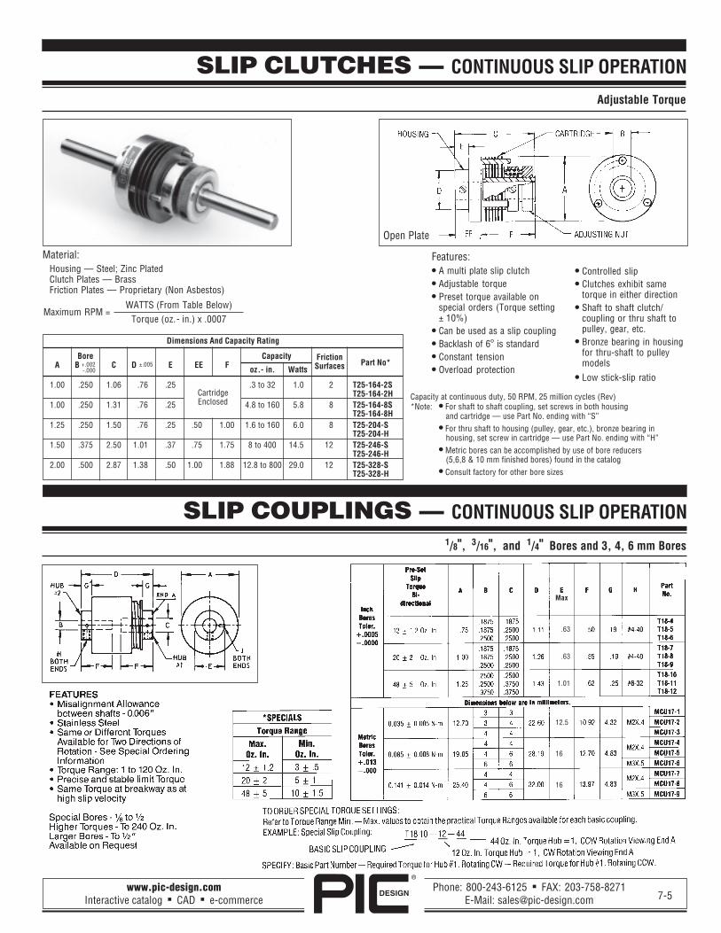
SLIP CLUTCHES — CONTINUOUS SLIP OPERATION
Adjustable Torque
Maximum RPM =WATTS (From Table Below)
Torque (oz.- in.) x .0007
Open Plate
Material:Housing — Steel; Zinc PlatedClutch Plates — BrassFriction Plates — Proprietary (Non Asbestos)
Features:● A multi plate slip clutch● Adjustable torque● Preset torque available on
special orders (Torque setting± 10%)
● Can be used as a slip coupling● Backlash of 6o is standard● Constant tension● Overload protection
● Controlled slip● Clutches exhibit same
torque in either direction● Shaft to shaft clutch/
coupling or thru shaft topulley, gear, etc.
● Bronze bearing in housingfor thru-shaft to pulleymodels
● Low stick-slip ratio
Dimensions And Capacity Rating
Bore Capacity FrictionA B C D E EE F oz.- in. Watts Surfaces Part No*
1.00 .250 1.06 .76 .25 .3 to 32 1.0 2 T25-164-2ST25-164-2H
1.00 .250 1.31 .76 .25 4.8 to 160 5.8 8 T25-164-8ST25-164-8H
1.25 .250 1.50 .76 .25 .50 1.00 1.6 to 160 6.0 8 T25-204-ST25-204-H
1.50 .375 2.50 1.01 .37 .75 1.75 8 to 400 14.5 12 T25-246-ST25-246-H
2.00 .500 2.87 1.38 .50 1.00 1.88 12.8 to 800 29.0 12 T25-328-ST25-328-H
CartridgeEnclosed
+.002-.000
±.005
Capacity at continuous duty, 50 RPM, 25 million cycles (Rev)*Note: ● For shaft to shaft coupling, set screws in both housing
and cartridge — use Part No. ending with “S”● For thru shaft to housing (pulley, gear, etc.), bronze bearing in
housing, set screw in cartridge — use Part No. ending with “H”● Metric bores can be accomplished by use of bore reducers
(5,6,8 & 10 mm finished bores) found in the catalog● Consult factory for other bore sizes
SLIP COUPLINGS — CONTINUOUS SLIP OPERATION1/8", 3/16", and 1/4" Bores and 3, 4, 6 mm Bores
Max
.63
.63
1.01
12.5
16
16
DESIGN
®
www.pic-design.comInteractive catalog ■ CAD ■ e-commerce
Phone: 800-243-6125 ■ FAX: 203-758-8271E-Mail: [email protected]
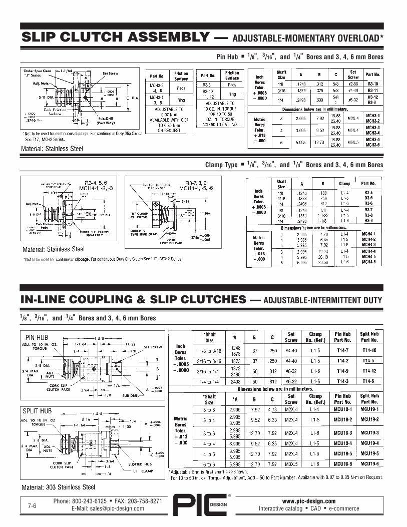
IN-LINE COUPLING & SLIP CLUTCHES — ADJUSTABLE-INTERMITTENT DUTY
1/8", 3/16", and 1/4" Bores and 3, 4, 6 mm Bores
7-6
SLIP CLUTCH ASSEMBLY — ADJUSTABLE-MOMENTARY OVERLOAD*
Pin Hub ■ 1/8", 3/16", and 1/4" Bores and 3, 4, 6 mm Bores
Clamp Type ■ 1/8", 3/16", and 1/4" Bores and 3, 4, 6 mm Bores
DESIGN
®
www.pic-design.comInteractive catalog ■ CAD ■ e-commerce
Phone: 800-243-6125 ■ FAX: 203-758-8271E-Mail: [email protected] 7-7
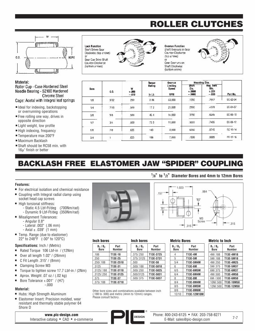
ROLLER CLUTCHES
■ Ideal for indexing, backstoppingor overrunning operations
■ Free rolling one way, drives inopposite direction
■ Light weight, low profile■ High indexing, frequency■ Temperature max 200°F■ Maximum Backlash■ Shaft should be RC58 min. with
16μ" finish or better
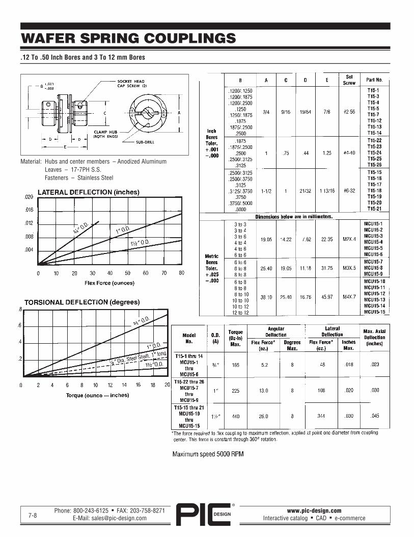
BACKLASH FREE ELASTOMER JAW “SPIDER” COUPLING1/8" to 1/2" Diameter Bores and 4mm to 12mm Bores
Features:■ For electrical isolation and chemical resistance■ Coupling with Integral radial clamp using
socket head cap screws■ High torsional stiffness:
- Static 4.5 Lbf-Ft/deg (700Nm/rad)- Dynamic 9 Lbf-Ft/deg (350Nm/rad)
■ Misalignment Tolerances:- Angular 0.8°- Lateral .002" (.06 mm)- Axial ± .039" (1 mm)
■ Temp. Range (due to elastomer)22° to 248°F (-30° to 120°C)
Specifications: Inch / (Metric)■ Rated Torque 106 Lbf-in / (12Nm)■ Over all length 1.02" / (26mm)■ C Fit Length .315" / (8mm)■ Clamping Screw M3■ Torque to tighten screw 17.7 Lbf-in / (2Nm)■ Aprox. Weight .07 oz / (.02 kg)■ Bore Tolerance +.001" / (H7) -.000Material:■ Hubs: High Strength Aluminum■ Elastomer Insert: Precision molded, wear
resistant and thermally stable polymer 64Shore D
1.023
.157
"B1"
"B2"
.315.315
.984
M3Screw
B1 / B2 PartBore Number
.188 T13E-18
.250 T13E-25
.250/.188 T13E-2518
.3125 T13E-31
.3125/.188 T13E-3118
.3125/.250 T13E-3125
.375 T13E-37
.375/.188 T13E-3718
Inch boresB1 / B2 PartBore Number
.375/.250 T13E-3725
.375/.3125 T13E-3731
.500 T13E-50
.500/.188 T13E-5018
.500/.250 T13E-5025
.500/3125 T13E-5031
.500/.375 T13E-5037
Inch boresB1 / B2 PartBore Number
4 T13E-4M5 T13E-5M5/4 T13E-5M4M6 T13E-6M6/5 T13E-6M5M6/4 T13E-6M4M8 T13E-8M8/4 T13E-8M4M8/5 T13E-8M5M8/6 T13E-8M6M12/10 T13E-12M10M
Metric Bores Metric to InchB1 / B2 PartBore Number
4M/.188 T13E-4M185M/.188 T13E-5M184M/.250 T13E-4M255M/.375 T13E-5M376M/.375 T13E-6M374M/.500 T13E-4M506M /.500 T13E-6M5010M/.500 T13E-10M5012M/.500 T13E-12M50
Other bore sizes and combinations available between inch(.188 to .500) and metric (4mm to 12mm) ranges.Please consult factory.
DESIGN
®
www.pic-design.comInteractive catalog ■ CAD ■ e-commerce
Phone: 800-243-6125 ■ FAX: 203-758-8271E-Mail: [email protected]
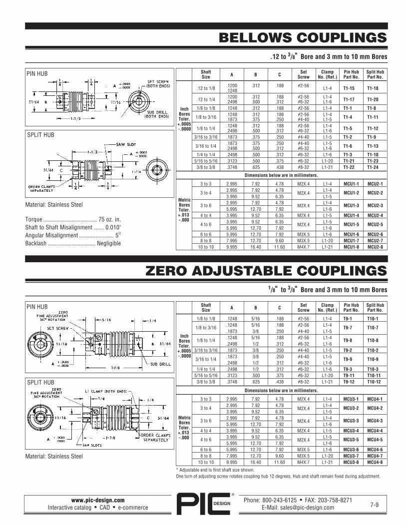
WAFER SPRING COUPLINGS.12 To .50 Inch Bores and 3 To 12 mm Bores
Material: Hubs and center members – Anodized AluminumLeaves – 17-7PH S.S.Fasteners – Stainless Steel
DESIGN
®
www.pic-design.comInteractive catalog ■ CAD ■ e-commerce
Phone: 800-243-6125 ■ FAX: 203-758-8271E-Mail: [email protected] 7-9
Shaft A B C Set Clamp Pin Hub Split HubSize Screw No. (Ref.) Part No. Part No.
.12 to 1/8 .1200 .312 .188 #2-56 L1-4 T1-15 T1-18.1248
.12 to 1/4 .1200 .312 .188 #2-56 L1-4 T1-17 T1-20.2498 .500 .312 #6-32 L1-61/8 to 1/8 .1248 .312 .188 #2-56 L1-4 T1-1 T1-8
1/8 to 3/16 .1248 .312 .188 #2-56 L1-4 T1-4 T1-11.1873 .375 .250 #4-40 L1-5
1/8 to 1/4 .1248 .312 .188 #2-56 L1-4 T1-5 T1-12.2498 .500 .312 #6-32 L1-63/16 to 3/16 .1873 .375 .250 #4-40 L1-5 T1-2 T1-9
3/16 to 1/4 .1873 .375 .250 #4-40 L1-5 T1-6 T1-13.2498 .500 .312 #6-32 L1-61/4 to 1/4 .2498 .500 .312 #6-32 L1-6 T1-3 T1-10
5/16 to 5/16 .3123 .500 .375 #6-32 L1-20 T1-21 T1-233/8 to 3/8 .3748 .625 .438 #8-32 L1-21 T1-22 T1-24
Dimensions below are in millimeters.
3 to 3 2.995 7.92 4.78 M2X.4 L1-4 MCU1-1 MCU2-1
3 to 4 2.995 7.92 4.78 L1-4 MCU1-2 MCU2-23.995 9.52 6.35 L1-5
3 to 6 2.995 7.92 4.78 L1-4 MCU1-3 MCU2-35.995 12.70 7.92 L1-6
4 to 4 3.995 9.52 6.35 M2X.4 L1-5 MCU1-4 MCU2-4
4 to 6 3.995 9.52 6.35 L1-5 MCU1-5 MCU2-55.995 12.70 7.92 L1-6
6 to 6 5.995 12.70 7.92 M3X.5 L1-6 MCU1-6 MCU2-68 to 8 7.995 12.70 9.60 M3X.5 L1-20 MCU1-7 MCU2-7
10 to 10 9.995 16.40 11.60 M4X.7 L1-21 MCU1-8 MCU2-8
Shaft A B C Set Clamp Pin Hub Split HubSize Screw No. (Ref.) Part No. Part No.
1/8 to 1/8 .1248 5/16 .188 #2-56 L1-4 T9-1 T10-1
1/8 to 3/16 .1248 5/16 .188 #2-56 L1-4 T9-7 T10-7.1873 3/8 .250 #4-40 L1-5
1/8 to 1/4 .1248 5/16 .188 #2-56 L1-4 T9-8 T10-8.2498 1/2 .312 #6-32 L1-6
3/16 to 3/16 .1873 3/8 .250 #4-40 L1-5 T9-2 T10-2
3/16 to 1/4 .1873 3/8 .250 #4-40 L1-5 T9-9 T10-9.2498 1/2 .312 #6-32 L1-6
1/4 to 1/4 .2498 1/2 .312 #6-32 L1-6 T9-3 T10-35/16 to 5/16 .3123 .500 .375 #6-32 L1-20 T9-11 T10-11
3/8 to 3/8 .3748 .625 .438 #8-32 L1-21 T9-12 T10-12
Dimensions below are in millimeters.
3 to 3 2.995 7.92 4.78 M2X.4 L1-4 MCU3-1 MCU4-1
3 to 4 2.995 7.92 4.78 L1-4 MCU3-2 MCU4-23.995 9.52 6.35 L1-5
3 to 6 2.995 7.92 4.78 L1-4 MCU3-3 MCU4-35.995 12.70 7.92 L1-6
4 to 4 3.995 9.52 6.35 M2X.4 L1-5 MCU3-4 MCU4-4
4 to 6 3.995 9.52 6.35 L1-5 MCU3-5 MCU4-55.995 12.70 7.92 L1-6
6 to 6 5.995 12.70 7.92 M3X.5 L1-6 MCU3-6 MCU4-68 to 8 7.995 12.70 9.60 M3X.5 L1-20 MCU3-7 MCU4-7
10 to 10 9.995 16.40 11.60 M4X.7 L1-21 MCU3-8 MCU4-8
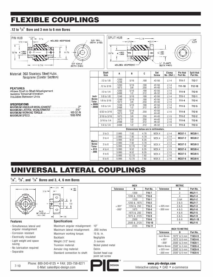
* Adjustable end is first shaft size shown.One turn of adjusting screw rotates coupling hub 12 degrees. Hub and shaft remain fixed during adjustment.
BELLOWS COUPLINGS.12 to 3/8" Bore and 3 mm to 10 mm Bores
InchBoresToler.+.0005-.0000
M2X.4
M2X.4
M2X.4
MetricBoresToler.+.013-.000
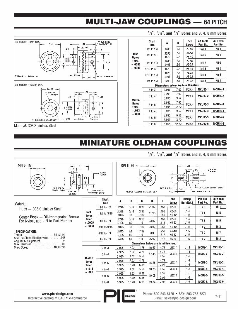
PIN HUB
SPLIT HUB
ZERO ADJUSTABLE COUPLINGS1/8" to 3/8" Bore and 3 mm to 10 mm Bores
PIN HUB
SPLIT HUB
Material: Stainless Steel
InchBoresToler.+.0005-.0000
MetricBoresToler.+.013-.000
M2X.4
M2X.4
M2X.4
Material: Stainless Steel
Torque .................................... 75 oz. in.Shaft to Shaft Misalignment ....... 0.010"Angular Misalignment ....................... 5O
Backlash ................................ Negligible
DESIGN
®
www.pic-design.comInteractive catalog ■ CAD ■ e-commerce
Phone: 800-243-6125 ■ FAX: 203-758-8271E-Mail: [email protected]
Shaft A B C Set Clamp Pin Hub Split HubSize Screw No. (Ref.) Part No. Part No.
.12 to 1/8 .1200 5/16 .188 #2-56 L1-4 T11-7 T12-7.1248
.12 to 3/16 .1200 5/16 .188 #2-56 L1-4 T11-10 T12-10.1873 3/8 .250 #4-40 L1-5
.12 to 1/4 .1200 5/16 .188 #2-56 L1-4 T11-9 T12-9.2498 1/2 .312 #6-32 L1-61/8 to 1/8 .1248 5/16 .188 #2-56 L1-4 T11-1 T12-1
1/8 to 3/16 .1248 5/16 .188 #2-56 L1-4 T11-4 T12-4.1873 3/8 .250 #4-40 L1-5
1/8 to 1/4 .1248 5/16 .188 #2-56 L1-4 T11-5 T12-5.2498 1/2 .312 #6-32 L1-6
5/32 to 3/16 .1562 5/16 .250 #2-56 L1-5 T11-8 T12-8.1873 3/8 #4-403/16 to 3/16 .1873 3/8 .250 #4-40 L1-5 T11-2 T12-2
3/16 to 1/4 .1873 3/8 .250 #4-40 L1-5 T11-6 T12-6.2498 1/2 .312 #6-32 L1-61/4 to 1/4 .2498 1/2 .312 #6-32 L1-6 T11-3 T12-3
Dimensions below are in millimeters.
3 to 3 2.995 7.92 4.78 M2X.4 L1-4 MCU7-1 MCU8-1
3 to 4 2.995 7.92 4.78 L1-4 MCU7-2 MCU8-23.995 9.52 6.35 L1-5
3 to 6 2.995 7.92 4.78 L1-4 MCU7-3 MCU8-35.995 12.70 7.92 L1-6
4 to 4 3.995 9.52 6.35 M2X.4 L1-5 MCU7-4 MCU8-4
4 to 6 3.995 9.52 6.35 L1-5 MCU7-5 MCU8-55.995 12.70 7.92 L1-6
6 to 6 5.995 12.70 7.92 M3X.5 L1-6 MCU7-6 MCU8-6
FLEXIBLE COUPLINGS.12 to 1/4" Bore and 3 mm to 6 mm Bores
7-10
PIN HUB
InchBoresToler.+.0005-.0000
SPLIT HUB
MetricBoresToler.+.013-.000
UNIVERSAL LATERAL COUPLINGS1/8", 3/8", and 1/4" Bores and 3, 4, 6 mm Bores
M2X.4
M2X.4
M2X.4
SpecificationsMaximum angular misalignment: 10o
Maximum lateral misalignment: .050 inchesMaximum working torque: 15 lb. in.Backlash: NegligibleWeight (1/2" bore): .5 ouncesTrunnion material: Nickel plated metalAnnular ring material: DelrinStandard connection to shaft: Socket head cup
point set screw
Features- Simultaneous lateral and
angular misalignment- Corrosion resistant- Electrically insulated- Light weight and space
saving- No lubrication required- Separable
INCHTolerance B Part No.
.1200 T16-7.1200 & .1250 T16-8
.1250 T16-1.1250 & .1875 T16-2
+.001" .1250 & .250 T16-3-.000" .1875 T16-4
.1875 & .250 T16-5.1875 & .3125 T16-9
.2500 T16-6.2500 & .3125 T16-10
.3125 T16-11
METRICTolerance B Part No.
3 MUJ1-14 MUJ1-4
3 &4 MUJ1-23 & 5 MUJ1-7
+.025 mm 3 & 6 MUJ1-3-.000 mm 4 & 5 MUJ1-8
4 & 6 MUJ1-55 & 5 MUJ1-95 & 6 MUJ1-10
6 MUJ1-6
INCH TO METRICTolerance B Part No.
Inch Bores .1875" & 5 mm T16C4-9+.001" .1875" & 6 mm T16C4-6-.000" .2500" & 3 mm T16C6-1
Metric Bores .2500" & 4 mm T16C6-4+.025 mm .2500" & 5 mm T16C6-9-.000 mm .2500" & 6 mm T16C6-6
DESIGN
®
www.pic-design.comInteractive catalog ■ CAD ■ e-commerce
Phone: 800-243-6125 ■ FAX: 203-758-8271E-Mail: [email protected] 7-11
MULTI-JAW COUPLINGS — 64 PITCH1/8", 3/16", and 1/4" Bores and 3, 4, 6 mm Bores
MINIATURE OLDHAM COUPLINGS1/8", 3/16", and 1/4" Bores and 3, 4, 6 mm Bores
48 TEETH - 3/4" DIA.
32 TEETH - 17/32" DIA.
DESIGN
®
www.pic-design.comInteractive catalog ■ CAD ■ e-commerce
Phone: 800-243-6125 ■ FAX: 203-758-8271E-Mail: [email protected]
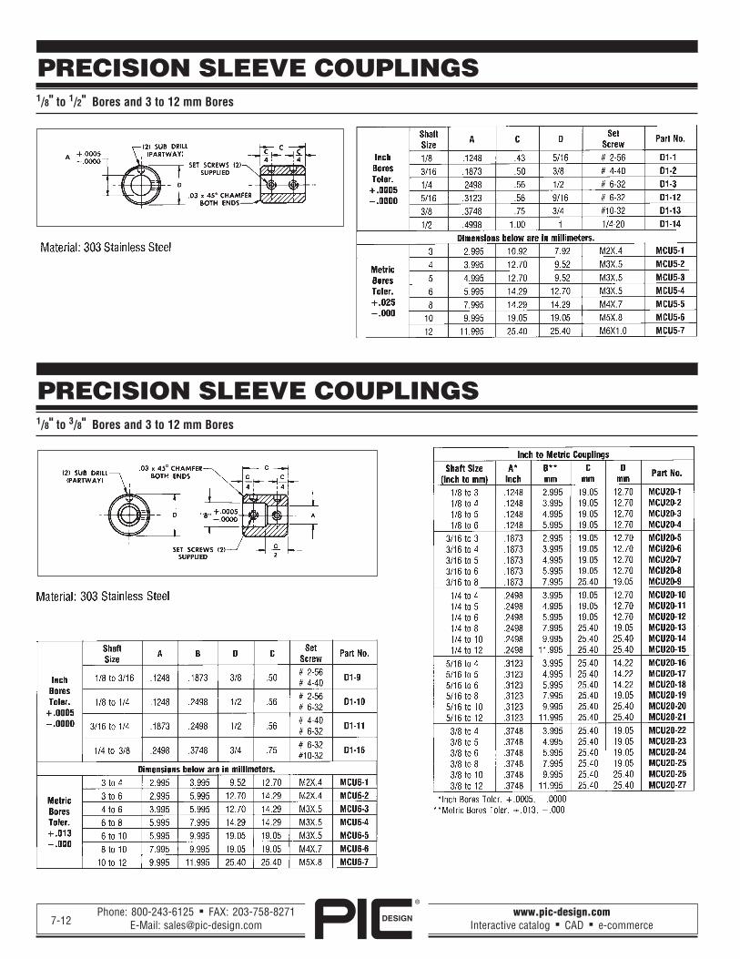
PRECISION SLEEVE COUPLINGS1/8" to 1/2" Bores and 3 to 12 mm Bores
PRECISION SLEEVE COUPLINGS1/8" to 3/8" Bores and 3 to 12 mm Bores
DESIGN
®
www.pic-design.comInteractive catalog ■ CAD ■ e-commerce
Phone: 800-243-6125 ■ FAX: 203-758-8271E-Mail: [email protected] 7-13
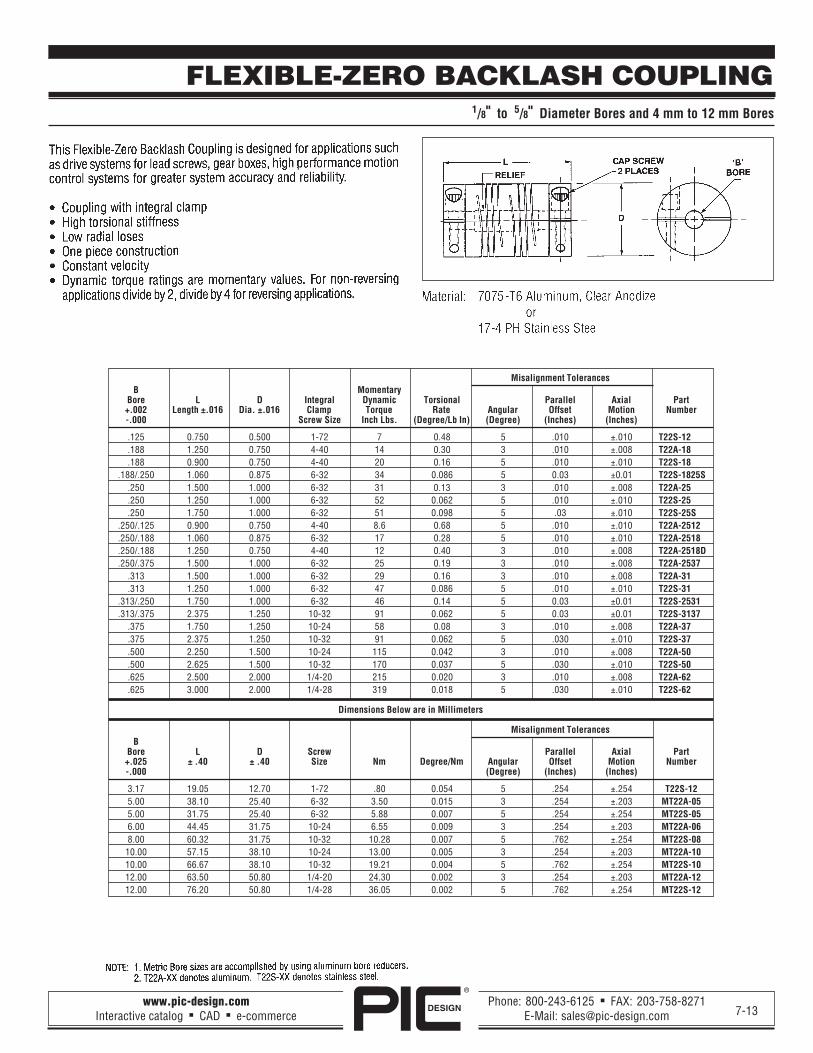
FLEXIBLE-ZERO BACKLASH COUPLING1/8" to 5/8" Diameter Bores and 4 mm to 12 mm Bores
Misalignment TolerancesB Momentary
Bore L D Integral Dynamic Torsional Parallel Axial Part+.002 Length ±.016 Dia. ±.016 Clamp Torque Rate Angular Offset Motion Number-.000 Screw Size Inch Lbs. (Degree/Lb In) (Degree) (Inches) (Inches)
.125 0.750 0.500 1-72 7 0.48 5 .010 ±.010 T22S-12
.188 1.250 0.750 4-40 14 0.30 3 .010 ±.008 T22A-18
.188 0.900 0.750 4-40 20 0.16 5 .010 ±.010 T22S-18.188/.250 1.060 0.875 6-32 34 0.086 5 0.03 ±0.01 T22S-1825S
.250 1.500 1.000 6-32 31 0.13 3 .010 ±.008 T22A-25
.250 1.250 1.000 6-32 52 0.062 5 .010 ±.010 T22S-25
.250 1.750 1.000 6-32 51 0.098 5 .03 ±.010 T22S-25S.250/.125 0.900 0.750 4-40 8.6 0.68 5 .010 ±.010 T22A-2512.250/.188 1.060 0.875 6-32 17 0.28 5 .010 ±.010 T22A-2518.250/.188 1.250 0.750 4-40 12 0.40 3 .010 ±.008 T22A-2518D.250/.375 1.500 1.000 6-32 25 0.19 3 .010 ±.008 T22A-2537
.313 1.500 1.000 6-32 29 0.16 3 .010 ±.008 T22A-31
.313 1.250 1.000 6-32 47 0.086 5 .010 ±.010 T22S-31.313/.250 1.750 1.000 6-32 46 0.14 5 0.03 ±0.01 T22S-2531.313/.375 2.375 1.250 10-32 91 0.062 5 0.03 ±0.01 T22S-3137
.375 1.750 1.250 10-24 58 0.08 3 .010 ±.008 T22A-37
.375 2.375 1.250 10-32 91 0.062 5 .030 ±.010 T22S-37
.500 2.250 1.500 10-24 115 0.042 3 .010 ±.008 T22A-50
.500 2.625 1.500 10-32 170 0.037 5 .030 ±.010 T22S-50
.625 2.500 2.000 1/4-20 215 0.020 3 .010 ±.008 T22A-62
.625 3.000 2.000 1/4-28 319 0.018 5 .030 ±.010 T22S-62
Dimensions Below are in Millimeters
Misalignment TolerancesB
Bore L D Screw Parallel Axial Part+.025 ± .40 ± .40 Size Nm Degree/Nm Angular Offset Motion Number-.000 (Degree) (Inches) (Inches)
3.17 19.05 12.70 1-72 .80 0.054 5 .254 ±.254 T22S-125.00 38.10 25.40 6-32 3.50 0.015 3 .254 ±.203 MT22A-055.00 31.75 25.40 6-32 5.88 0.007 5 .254 ±.254 MT22S-056.00 44.45 31.75 10-24 6.55 0.009 3 .254 ±.203 MT22A-068.00 60.32 31.75 10-32 10.28 0.007 5 .762 ±.254 MT22S-08
10.00 57.15 38.10 10-24 13.00 0.005 3 .254 ±.203 MT22A-1010.00 66.67 38.10 10-32 19.21 0.004 5 .762 ±.254 MT22S-1012.00 63.50 50.80 1/4-20 24.30 0.002 3 .254 ±.203 MT22A-1212.00 76.20 50.80 1/4-28 36.05 0.002 5 .762 ±.254 MT22S-12
DESIGN
®
www.pic-design.comInteractive catalog ■ CAD ■ e-commerce
Phone: 800-243-6125 ■ FAX: 203-758-8271E-Mail: [email protected]
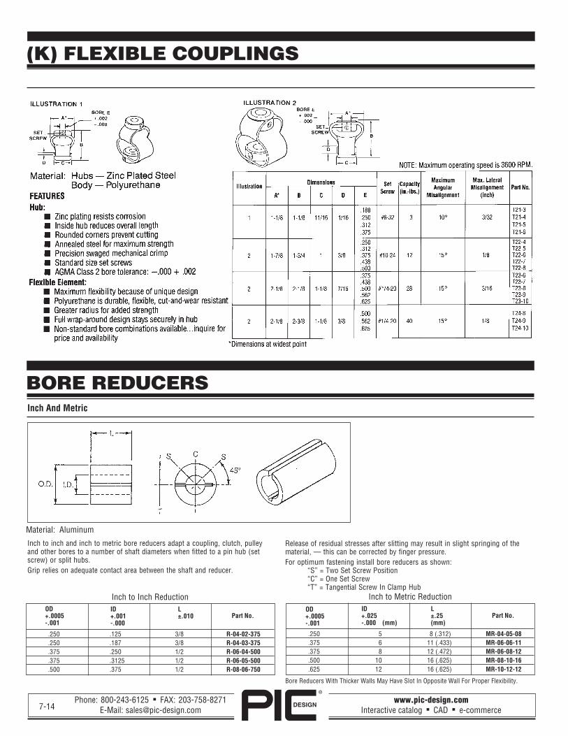
(K) FLEXIBLE COUPLINGS
BORE REDUCERSInch And Metric
Material: Aluminum
Inch to inch and inch to metric bore reducers adapt a coupling, clutch, pulleyand other bores to a number of shaft diameters when fitted to a pin hub (setscrew) or split hubs.Grip relies on adequate contact area between the shaft and reducer.
Release of residual stresses after slitting may result in slight springing of thematerial, — this can be corrected by finger pressure.For optimum fastening install bore reducers as shown:
“S” = Two Set Screw Position“C” = One Set Screw“T” = Tangential Screw In Clamp Hub
.250 .125 3/8 R-04-02-375
.250 .187 3/8 R-04-03-375
.375 .250 1/2 R-06-04-500
.375 .3125 1/2 R-06-05-500
.500 .375 1/2 R-08-06-750
Part No.OD+.0005-.001
ID+.001-.000
Inch to Inch ReductionL±.010
.250 5 8 (.312) MR-04-05-08
.375 6 11 (.433) MR-06-06-11
.375 8 12 (.472) MR-06-08-12
.500 10 16 (.625) MR-08-10-16
.625 12 16 (.625) MR-10-12-12
Part No.
Inch to Metric ReductionL±.25(mm)
ID+.025-.000 (mm)
OD+.0005-.001
Bore Reducers With Thicker Walls May Have Slot In Opposite Wall For Proper Flexibility.
DESIGN
®
www.pic-design.comInteractive catalog ■ CAD ■ e-commerce
Phone: 800-243-6125 ■ FAX: 203-758-8271E-Mail: [email protected] 7-15
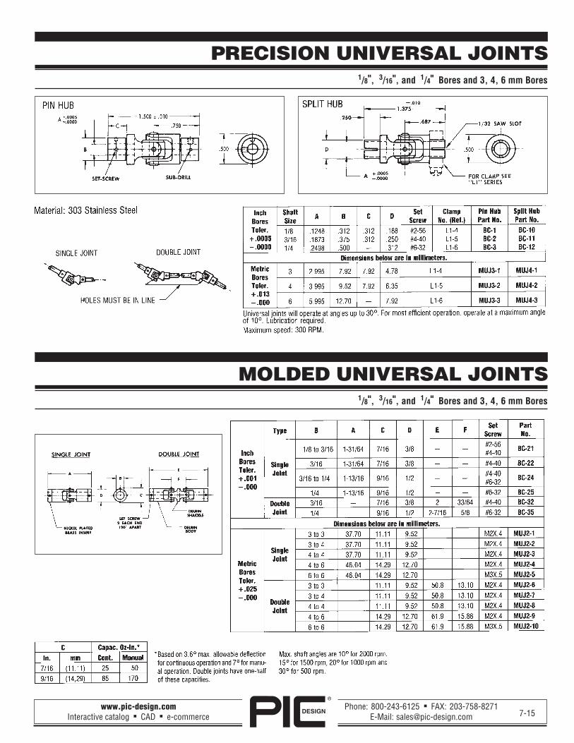
PRECISION UNIVERSAL JOINTS1/8", 3/16", and 1/4" Bores and 3, 4, 6 mm Bores
MOLDED UNIVERSAL JOINTS1/8", 3/16", and 1/4" Bores and 3, 4, 6 mm Bores