Embed Size (px)
Citation preview
2017 SEAOC CONVENTION PROCEEDINGS
1
Lessons from Stadium Structures in Seismic Zones
Rafael Sabelli, Director of Seismic Design Walter P Moore
San Francisco, California Laura Whitehurst, Senior Project Engineer
Holmes Consulting Wellington, New Zealand
Abstract Stadium structures are a special category of structures with
many conditions not addressed in building codes or published
design examples. Drawing on recent projects (by the authors
and others), design approaches to such special conditions as
multi-story transfer trusses, sloped raker girders, thermal
jointing, switch-back ramp systems, and curved, sloped seating
bowls are discussed. These lessons highlight the importance of
addressing seismic response by accommodating large
displacements.
Introduction
Stadium structures are a special category of structures with
many conditions not addressed in building codes or published
design examples. The special configurations required for this
type of structure pose special challenges in seismic design
related to providing ductility and accommodating inelastic
drift.
Terminology Concourse Large floor areas outside of the seating bowl
used for circulation, concessions, and services.
Event level Field level, typically the lowest level of the
stadium.
Moat Space separating stadium structure from the
retained earth.
Raker Diagonal beam supporting seating tiers.
Seating bowl Multi-story assembly of seating tiers and
rakers.
Seating tier L-shaped or Z-shaped beam that spans
between rakers and forms the seating area of a
stadium.
SLRS Seismic load resisting system
Vomitory Opening in a seating bowl to allow spectators
to enter
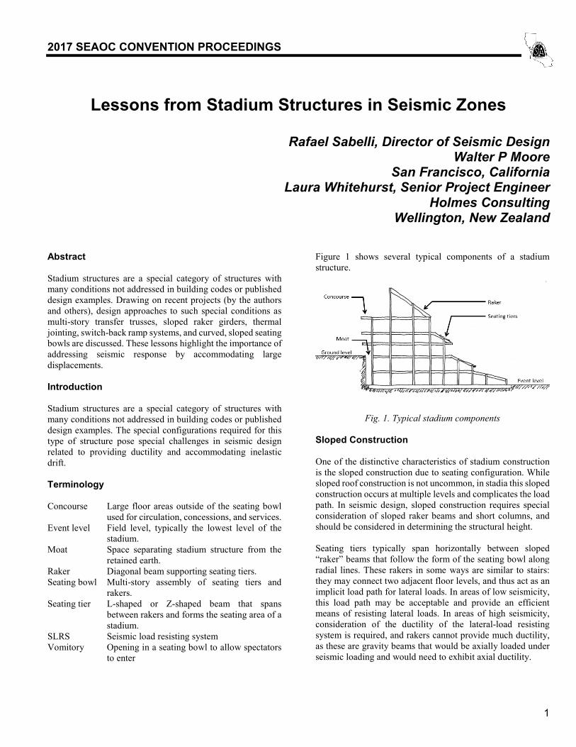
Figure 1 shows several typical components of a stadium
structure.
Fig. 1. Typical stadium components
Sloped Construction One of the distinctive characteristics of stadium construction
is the sloped construction due to seating configuration. While
sloped roof construction is not uncommon, in stadia this sloped
construction occurs at multiple levels and complicates the load
path. In seismic design, sloped construction requires special
consideration of sloped raker beams and short columns, and
should be considered in determining the structural height.
Seating tiers typically span horizontally between sloped
“raker” beams that follow the form of the seating bowl along
radial lines. These rakers in some ways are similar to stairs:
they may connect two adjacent floor levels, and thus act as an
implicit load path for lateral loads. In areas of low seismicity,
this load path may be acceptable and provide an efficient
means of resisting lateral loads. In areas of high seismicity,
consideration of the ductility of the lateral-load resisting
system is required, and rakers cannot provide much ductility,
as these are gravity beams that would be axially loaded under
seismic loading and would need to exhibit axial ductility.

2017 SEAOC CONVENTION PROCEEDINGS
2
These rakers are typically sized to prevent objectionable
vibrations. They may have substantial area, and ductility
demands may occur in connections. To avoid such ductility
demands, slip connections similar to those used for stairs may
be employed. As these connections are typically subject to
high gravity forces, low-friction connections may be
considered to make the behavior more predictable.
In some cases, the lower support of the sloped raker occurs
significantly above the floor level below, typically on a column
that may be short compared to those supporting the upper end
of the raker and the flat concourse. The sloped, curved
construction of the raker and seating tiers will move essentially
as a rigid body. Thus the drift at the top of the short column
will be the same as the drift at the concourse, but the effective
drift ratio of this column is amplified by the ratio of the story
height to the column height. Figure 2 shows a schematic of this
movement.
Fig. 2. Schematic of amplified drift in short columns
While ASCE 7 drift limits do not apply to this condition, it is
recommended that if this movement imposes large inelastic
rotation of the column, compact column sections should be
used. Additionally, the required rotation should be considered
in the design of the column connections so that gravity support
is not lost. Further, the analysis model should consider these
columns as pin-pin members to avoid “stealing” load from the
designated SLRS.
The sloped construction of the upper level of an open-air
stadium may be considered to be the roof of the structure for
purposes of determining structural height. ASCE 7 has
clarified that structural height is measured from the base to the
mean roof height. In the case of open-air stadia, the latter point
can be taken as the center of mass of the upper seating level.
Temperature changes Stadium structures can be quite large. Often the length exceeds
700 feet. Even in moderate climates such lengths result in very
large thermal expansion, and it is necessary to analyze thermal
effects. The greatest differential thermal expansion typically is
between the ground floor (which is restrained by the
foundation and is also less likely to reach peak temperatures)
and the second floor, which is only restrained form thermal
expansion or contraction by the SLRS and bending of columns.
ASCE 7 does not specify a temperature range to consider, nor
the appropriate load combinations, but does require
consideration of self-straining loads. Examples abound of
poorly configured structures that have sustained damage
through a combination of temperature swings and concrete
shrinkage.
Buckling-restrained braces offer a unique advantage over other
braced frames in the design for thermal loads. Most elements
that attract high forces due to temperature changes offer very
little ductility. These elements must be designed to resist the
forces corresponding to the maximum temperature swing that
is deemed appropriate to consider. (This temperature swing is
typically with respect to an unknown but moderate
construction temperature, and is combined with concrete
shrinkage.) Buckling-restrained braces, however, offer very
high ductility, and the ductility demands corresponding to
temperature effects is typically a small percentage of both the
maximum and cumulative ductility capacity of the brace. It is
reasonable to allow some yielding of these braces under the
maximum thermal loads, providing that yielding does not
occur regularly. (That is, a frequent temperature range —
perhaps 25 years—may be considered for evaluating the
braces.) Such yielding has no effect on the lateral strength of
the braces, and effectively releases the shrinkage-induced
stresses.
Jointing Stadium configuration takes into account the immense entry
and exiting requirements. One result of this is that it is
generally beneficial to have the event level (the playing field)
well below ground level, which allows people to enter at the
mid-height of the structure and disperse more quickly. In this
case, a substantial retention system is required. The below
grade structure may be integrated with that retention system—
requiring analysis of complex soil-structure interactions—or it
may be separate, resulting in a seismic base at event level and
a structure that is effectively much taller. With the latter
approach a substantial seismic separation is required at the
ground level (a “moat”). This separation must be sized for
movements of both the retention system and the stadium, and
joint covers used for exiting must remain operational under the
design event. Consideration of the consequences under other
events, such as a more frequent event or the maximum
considered event, should be discussed with the owner.
Typically temperature-induced effects may be reduced by
placing frames near the midpoint of the building along the
frame line. Such an approach is insufficient for stadia due to
the large dimensions and the large transverse thermal
movement, as well as ring-effects of a circular plan creating no
“midpoint”. Instead, the typical approach is to introduce
thermal joints along radial lines such that the building is
divided into a number of wedges that can expand and contract

2017 SEAOC CONVENTION PROCEEDINGS
3
with respect to their individual centers of rigidity, thus greatly
reducing the maximum thermal movement. Such joints also
divide the lateral system, such that each wedge requires a
separate system and a separate analysis. Relative movements
at upper stories can become quite large, and the joint sizes
follow suit. Double columns (one on each side of the joint) are
often employed at these seismic joints instead of slip
connections to preclude the possibility of loss of gravity
support of a beam subject to such large displacements. Figure
3 shows a schematic of a stadium plan with such jointing.
Fig. 3. Stadium plan with thermal joints.
The individual wedge shapes that result from thermal jointing
are not well configured for efficient seismic resistance. They
may approach a triangular form, with the center of mass offset
at every level due to the seating configuration. These
characteristics can lead to a high torsional response, and the
need for much additional strengthening and stiffening.
Lock-up devices One alternative to having seismically independent wedges is
to interconnect the wedges across the thermal joints with
“lock-up devices” (LUDs) that provide negligible restraint for
slow loading (such as thermal) but provide a high degree of
restraint for faster loads (such as seismic). LUDs are typically
viscous dampers proportioned to provide these force-velocity
characteristics. This allows the relative movement under
temperature swings necessary to prevent overloading of the
structure, while providing an efficient seismic system that can
reduce the torsional response of the structure. Each wedge still
requires a complete lateral-load-resisting system for gravity
stability, but the SLRS as a whole will be more efficient.
Using such an approach, joints are sized for the relatively small
thermal movement (which do not increase with height), rather
than the large seismic movements (which generally approach
the drift limits for taller structures).
A structure interconnected by such LUDs act as a single
structure with respect to seismic loads. Thus the torsional
resistance corresponds that of the entire system of
circumferential frames, rather than that of the unusual,
triangular configuration of radial and circumferential frames
within a wedge. This configuration tends to have a much lower
torsional response.
These LUDs may be located across thermal joints at every
level. Complete connection of the two diaphragm segments
requires three connections. Two connections at or near the
boundaries along circumferential lines provide constraint in
one translational direction and in rotation. A shear connection
on the radial line provides constraint in the orthogonal
translation direction. This last constraint does not require
accommodation of large thermal movement in the direction of
force and may be done using more conventional methods such
as slotted holes (not loaded in shear under gravity); transverse
movement under temperature swings must be accommodated.
Figure 4 shows a schematic of LUDs at a thermal joint.
Fig. 4. Schematic of lock-up-device at thermal joint
Because the thermal effects are greatest at the first floor it is
possible to discontinue them at some point above the second
floor. This location is likely not the third level. Careful thermal
analyses must be performed to ensure that the differential
movement between the jointed level and the adjacent
continuous level does not induce excessive force in any
element. The combination of jointless upper levels and lower
levels interconnected by LUDs minimizes the intrusiveness of
joints by reducing their number and size, and provides for an
efficient seismic system.
SLRS Complexity A complex and large structure such as a stadium requires well-
distributed seismic resistance. The number of bays of lateral
load-resisting elements (braces, walls) can easily exceed a
thousand for a large stadium. Due to the different functions at
each level (e.g., locker rooms, suites, concourses), the
architectural programming can also lead to highly inefficient
systems, including in-plane and out-of-plane discontinuities in
the lateral load path. The structure can also react in ways that
might seem counterintuitive to the engineer experienced in
normal building design (such as highly torsional response that
is not easily controlled). All of these factors can lead to a
SLRS system that is not easy to proportion based on hand
methods and requires a three –dimensional analysis.
2017 SEAOC CONVENTION PROCEEDINGS
4
The authors recommend an iterative approach, in which initial
sizes are chosen at each level of the stadium using back-of-the-
envelope calculation to determine the rough area of SLRS
needed to resist the base shear, providing that area in the
available bays at the base level, and then incrementally
decreasing that area at each level going up the building. Once
these rough sizes have been implemented, an initial analysis
can be completed and the behavior of the building assessed.
Some elements will be overstressed and some will be
understressed. The overstressed elements should be upsized
relative to their demand-capacity ratio (e.g., a brace that has a
DCR of 1.30 should have its area increased by 30%). The
understressed elements should only be downsized by a
predetermined ratio (such as ¾ or 2/3). This incremental
downsizing avoids a feedback loop wherein the understressed
element gets drastically smaller and less stiff, and therefore
attracts less load, which triggers it being downsized further,
becoming less stiff, etc.
After all the elements are resized, the model should be re-
analyzed and the sizing process repeated until all elements
have DCR’s less than one. This iteration can be done
manually, but it may be more convenient to program an
algorithm to run the process without constant input from the
engineer.
Accidental Eccentricity ASCE 7’s approach to accidental eccentricity is intended to
capture mislocated mass and building torsional sensitivity.
The approach applies a torsional moment corresponding to the
diaphragm mass placed at an eccentricity of 5% of the building
dimension. This method is targeted at structures without large
diaphragm discontinuities. Stadia inherently have large
openings or re-entrant corners in the diaphragm at every level
(possibly excluding the event level and the roof, if there is
one). By taking the full out-to-out dimension of a stadium
bowl, the ASCE 7 method therefore implies a very large
misplacement of mass, disregarding the fact that there is no
mass in the “donut hole” in the middle of the diaphragm
opening. Conservatively, this large accidental torsion could be
considered to place a strong emphasis on preventing torsional
response, but the authors feel that further investigation may be
desired to avoid this perhaps unwarranted penalty on the
structure.
Conventional structural analysis software is not capable of
capturing the ASCE 7-mandated accidental eccentricity in a
complicated sloping structure such as a stadium bowl. The
authors suggest summing up the seismic mass tributary to each
diaphragm, multiplying that mass by the prescribed
dimensions, and amplifying as necessary per ASCE 7 to find
the total accidental torsion on each level. The accidental
eccentricity torsion can be distributed as point-moments
applied to the main diaphragms at suitably small intervals
(such as every grid intersection) so that the local effects near
the application point are moderate.
Non-Orthogonality A stadium bowl is typically curved to allow optimal views to
the playing area, which inherently requires a non-orthogonal
structure. This non-orthogonality constitutes a Type 5
horizontal irregularity per ASCE 7, and also requires special
consideration of application of seismic loads.
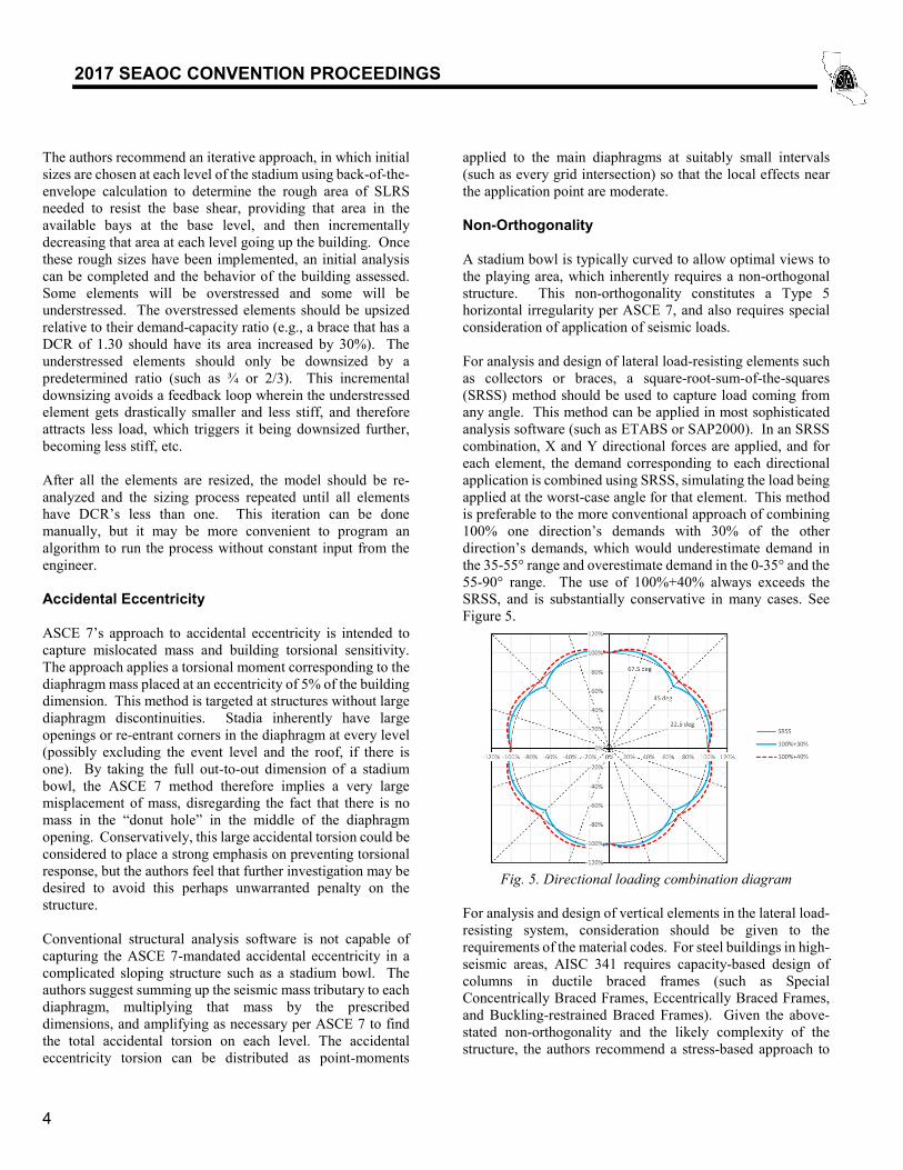
For analysis and design of lateral load-resisting elements such
as collectors or braces, a square-root-sum-of-the-squares
(SRSS) method should be used to capture load coming from
any angle. This method can be applied in most sophisticated
analysis software (such as ETABS or SAP2000). In an SRSS
combination, X and Y directional forces are applied, and for
each element, the demand corresponding to each directional
application is combined using SRSS, simulating the load being
applied at the worst-case angle for that element. This method
is preferable to the more conventional approach of combining
100% one direction’s demands with 30% of the other
direction’s demands, which would underestimate demand in
the 35-55° range and overestimate demand in the 0-35° and the
55-90° range. The use of 100%+40% always exceeds the
SRSS, and is substantially conservative in many cases. See
Figure 5.
Fig. 5. Directional loading combination diagram
For analysis and design of vertical elements in the lateral load-
resisting system, consideration should be given to the
requirements of the material codes. For steel buildings in high-
seismic areas, AISC 341 requires capacity-based design of
columns in ductile braced frames (such as Special
Concentrically Braced Frames, Eccentrically Braced Frames,
and Buckling-restrained Braced Frames). Given the above-
stated non-orthogonality and the likely complexity of the
structure, the authors recommend a stress-based approach to
2017 SEAOC CONVENTION PROCEEDINGS
5
simulating the applied load equivalent to the capacity of the
horizontal lateral load-resisting elements, which takes
advantage of the capabilities of analysis programs to evaluate
complex configurations.
A method that the authors have used is the application of
fictitious temperature load that corresponds to the tension or
compression capacity of an element. This approach requires
greatly decreasing the modulus of elasticity so that the stresses
induced in each brace element are due only to this imposed
temperature self-straining load, combined with restraint at the
diaphragm levels (which are not allowed to translate). The
element capacities should be combined in a way to impose the
worst case loading on a column from all braces connecting to
it simultaneously. In a regular, orthogonal building, this would
be simple enough to combine (±Assumed Force in X ±
Assumed Force in Y). However, in an irregular, non-
orthogonal building such as a stadium, this approach would
miss the full capacities for elements not oriented with X or Y.
Therefore another strategy must be used.
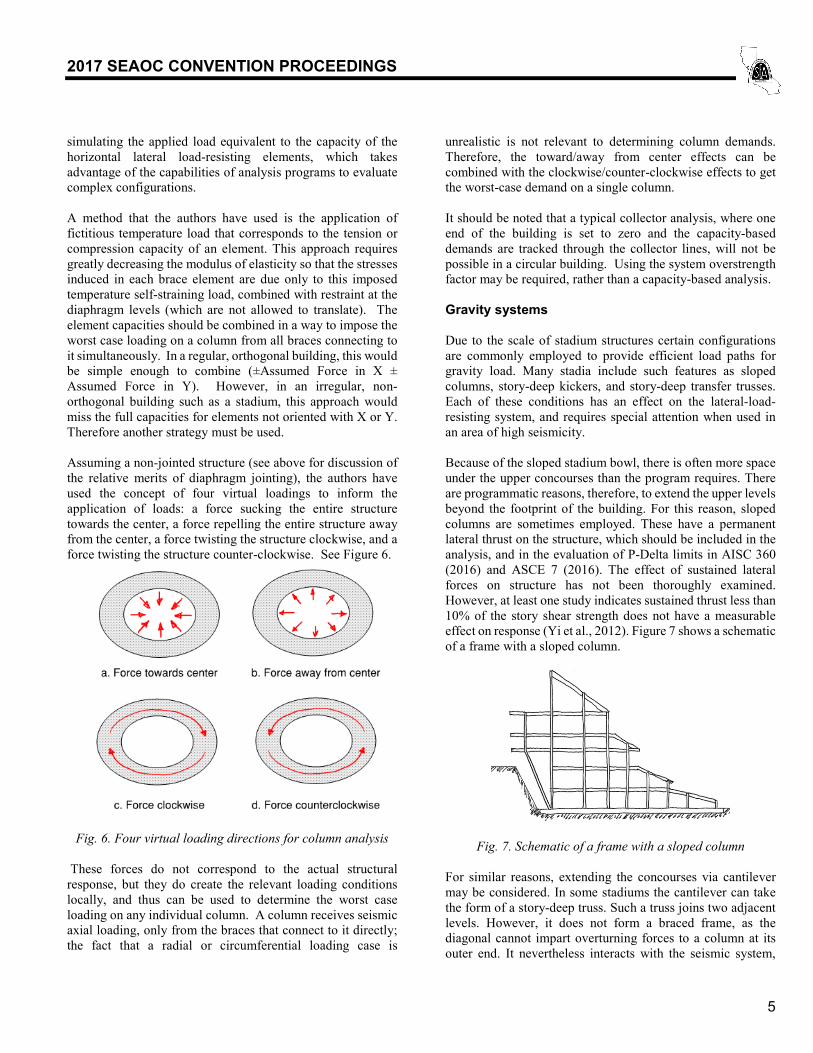
Assuming a non-jointed structure (see above for discussion of
the relative merits of diaphragm jointing), the authors have
used the concept of four virtual loadings to inform the
application of loads: a force sucking the entire structure
towards the center, a force repelling the entire structure away
from the center, a force twisting the structure clockwise, and a
force twisting the structure counter-clockwise. See Figure 6.
Fig. 6. Four virtual loading directions for column analysis
These forces do not correspond to the actual structural
response, but they do create the relevant loading conditions
locally, and thus can be used to determine the worst case
loading on any individual column. A column receives seismic
axial loading, only from the braces that connect to it directly;
the fact that a radial or circumferential loading case is
unrealistic is not relevant to determining column demands.
Therefore, the toward/away from center effects can be
combined with the clockwise/counter-clockwise effects to get
the worst-case demand on a single column.
It should be noted that a typical collector analysis, where one
end of the building is set to zero and the capacity-based
demands are tracked through the collector lines, will not be
possible in a circular building. Using the system overstrength
factor may be required, rather than a capacity-based analysis.
Gravity systems
Due to the scale of stadium structures certain configurations
are commonly employed to provide efficient load paths for
gravity load. Many stadia include such features as sloped
columns, story-deep kickers, and story-deep transfer trusses.
Each of these conditions has an effect on the lateral-load-
resisting system, and requires special attention when used in
an area of high seismicity.
Because of the sloped stadium bowl, there is often more space
under the upper concourses than the program requires. There
are programmatic reasons, therefore, to extend the upper levels
beyond the footprint of the building. For this reason, sloped
columns are sometimes employed. These have a permanent
lateral thrust on the structure, which should be included in the
analysis, and in the evaluation of P-Delta limits in AISC 360
(2016) and ASCE 7 (2016). The effect of sustained lateral
forces on structure has not been thoroughly examined.
However, at least one study indicates sustained thrust less than
10% of the story shear strength does not have a measurable
effect on response (Yi et al., 2012). Figure 7 shows a schematic
of a frame with a sloped column.
Fig. 7. Schematic of a frame with a sloped column
For similar reasons, extending the concourses via cantilever
may be considered. In some stadiums the cantilever can take
the form of a story-deep truss. Such a truss joins two adjacent
levels. However, it does not form a braced frame, as the
diagonal cannot impart overturning forces to a column at its
outer end. It nevertheless interacts with the seismic system,

2017 SEAOC CONVENTION PROCEEDINGS
6
being essentially a highly-sloped column, imposing similar
sustained thrust on the lateral system. Additionally, the vertical
movement of the cantilever is coupled with the lateral drift,
and the geometry may be such that the vertical movements are
an amplification of the horizontal. While this is not inherently
a performance issue, it may be disconcerting to experience.
Figure 8 shows a story-deep kicker.
Fig. 8. Schematic of a frame with a story-deep kicker
Because of special programming requirements at event level
such as loading docks, transfer trusses are often used to allow
closer column spacing at upper levels. Such trusses often
support several levels of structure and must be quite deep to
provide sufficient strength for the loading and stiffness for
erection. These trusses may be a full story deep. If both the top
and bottom chord are engaged into their respective levels, only
very small inelastic drift is possible unless the gravity-carrying
truss webs are subject to axial ductility (which would
compromise the gravity system). This can be avoided by
detaching one of the two chords from the diaphragm. Such
detachment needs to be preserved even as the chord is braced
laterally. Figure 9 shows a story-deep transfer truss.
Fig. 9. Story-deep transfer truss
It is typically much more efficient to locate braced frames at
upper levels away from columns supported by transfer trusses.
The large overturning forces associated with ductile braced
frames would require substantial increases in truss-member
size, constituting a much larger penalty than coping with
inefficiencies in braced-frame layout.
Seating Stadium bowls typically consist of flat concourses with seating
bowls sloping down and away, cantilevering toward the
playing area. The main diaphragm is typically the flat cast-in-
place concrete or flat slab on metal deck, similar to more
typical buildings. The seating bowl is necessarily a stepped
structure which cantilevers laterally and vertically off the main
diaphragm. Careful attention must be paid to the seismic load
path in tracing these loads back to the main SLRS.
Currently, two predominant options are available to provide
the structure for the seating bowls: precast concrete seating
units and proprietary systems such as the Sandwich Plate
System (SPS). The precast option is the more traditional
method, and consists of planks of precast concrete formed into
“Z” shapes one or two rows high (see Figure 10). These then
span from raker to raker, typically with a horizontal slip
connection at one end to prevent cracking under thermal loads.
The individual seating units are connected together and can
span laterally over their own length in the transverse direction,
but do not act as a full diaphragm over multiple bays.
Therefore, a supplementary diaphragm must be provided to
carry these forces back to the main diaphragm. See further
discussion of this “under-bowl” diaphragm below.
Fig. 10. Precast seating unit schematic cross section
SPS seating consists of two steel plates with an elastomer core
sandwiched between them, again formed into Z-shaped
sections. The two plates act as flanges resisting bending, while
the core transmits shear. See Figure 11. The plates also
transmit in-plane shear, allowing them to act as a diaphragm.
SPS seating is much lighter than equivalent concrete systems
(as little as 20% of the concrete weight, according to the
manufacturer), which can reduce the seismic mass of the
structure. However, in stadia with wide expanses of flat slabs
driving the bulk of the seismic mass (e.g., extensive
concourses or box seating), the potential mass savings may be
outweighed by the higher cost of the SPS units.
2017 SEAOC CONVENTION PROCEEDINGS
7
Fig. 11. Sandwich Plate System schematic cross section
Under-bowl diaphragms
For systems that do not inherently have diaphragm capacity, a
supplementary diaphragm must be provided. This diaphragm
is typically accomplished by using a steel truss underneath the
seating units. Several complications arise in using this
configuration that must be carefully considered by the design
engineer.
• The diaphragm is vertically eccentric to the mass.
The truss diaphragm will need to be located below the
deepest stems of the seating units above. It may be
convenient to locate the truss members at the
centerline of the rakers, but the lower the truss is
located relative to the seating units, the more bending
will need to be taken by the rakers and other axially-
loaded collector members.
• The seating units are typically axially released on one
end to prevent the build-up of thermal stresses. This
release means that longitudinal seismic loads have to
track back to the fixed end. The connection from the
seating unit to the raker should be checked for this
full load. This configuration can also result in minor-
axis bending and torsion in the rakers. Rakers
typically have fixed-end units framing from one side
and free-end units framing from the other side. The
fixed-end units will induce bending which would not
be resisted by the free-end units.
• The entire under-bowl diaphragm may not line up
with the main diaphragm. Some bowls may be
stepped down from the main diaphragm, requiring
careful detailing to transfer the bowl forces into the
main diaphragm. Examples include kickers, braces,
or short “shear walls” that span from the top of the
bowl diaphragm up to the main diaphragm.
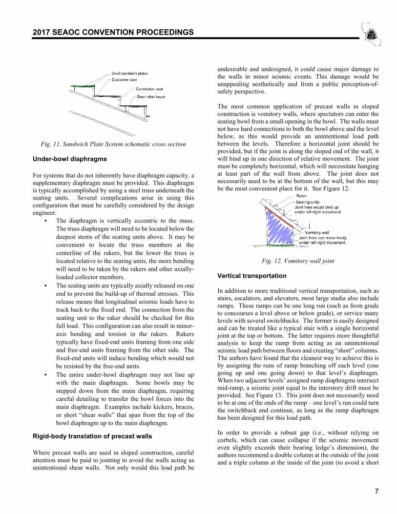
Rigid-body translation of precast walls
Where precast walls are used in sloped construction, careful
attention must be paid to jointing to avoid the walls acting as
unintentional shear walls. Not only would this load path be
undesirable and undesigned, it could cause major damage to
the walls in minor seismic events. This damage would be
unappealing aesthetically and from a public perception-of-
safety perspective.
The most common application of precast walls in sloped
construction is vomitory walls, where spectators can enter the
seating bowl from a small opening in the bowl. The walls must
not have hard connections to both the bowl above and the level
below, as this would provide an unintentional load path
between the levels. Therefore a horizontal joint should be
provided, but if the joint is along the sloped end of the wall, it
will bind up in one direction of relative movement. The joint
must be completely horizontal, which will necessitate hanging
at least part of the wall from above. The joint does not
necessarily need to be at the bottom of the wall, but this may
be the most convenient place for it. See Figure 12.
Fig. 12. Vomitory wall joint
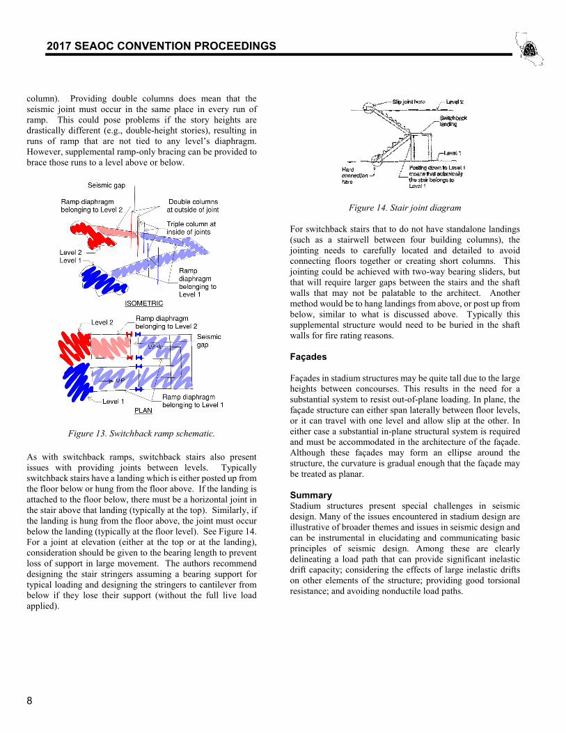
Vertical transportation
In addition to more traditional vertical transportation, such as
stairs, escalators, and elevators, most large stadia also include
ramps. These ramps can be one long run (such as from grade
to concourses a level above or below grade), or service many
levels with several switchbacks. The former is easily designed
and can be treated like a typical stair with a single horizontal
joint at the top or bottom. The latter requires more thoughtful
analysis to keep the ramp from acting as an unintentional
seismic load path between floors and creating “short” columns.
The authors have found that the cleanest way to achieve this is
by assigning the runs of ramp branching off each level (one
going up and one going down) to that level’s diaphragm.
When two adjacent levels’ assigned ramp diaphragms intersect
mid-ramp, a seismic joint equal to the interstory drift must be
provided. See Figure 13. This joint does not necessarily need
to be at one of the ends of the ramp – one level’s run could turn
the switchback and continue, as long as the ramp diaphragm
has been designed for this load path.
In order to provide a robust gap (i.e., without relying on
corbels, which can cause collapse if the seismic movement
even slightly exceeds their bearing ledge’s dimension), the
authors recommend a double column at the outside of the joint
and a triple column at the inside of the joint (to avoid a short
2017 SEAOC CONVENTION PROCEEDINGS
8
column). Providing double columns does mean that the
seismic joint must occur in the same place in every run of
ramp. This could pose problems if the story heights are
drastically different (e.g., double-height stories), resulting in
runs of ramp that are not tied to any level’s diaphragm.
However, supplemental ramp-only bracing can be provided to
brace those runs to a level above or below.
Figure 13. Switchback ramp schematic.
As with switchback ramps, switchback stairs also present
issues with providing joints between levels. Typically
switchback stairs have a landing which is either posted up from
the floor below or hung from the floor above. If the landing is
attached to the floor below, there must be a horizontal joint in
the stair above that landing (typically at the top). Similarly, if
the landing is hung from the floor above, the joint must occur
below the landing (typically at the floor level). See Figure 14.
For a joint at elevation (either at the top or at the landing),
consideration should be given to the bearing length to prevent
loss of support in large movement. The authors recommend
designing the stair stringers assuming a bearing support for
typical loading and designing the stringers to cantilever from
below if they lose their support (without the full live load
applied).
Figure 14. Stair joint diagram
For switchback stairs that to do not have standalone landings
(such as a stairwell between four building columns), the
jointing needs to carefully located and detailed to avoid
connecting floors together or creating short columns. This
jointing could be achieved with two-way bearing sliders, but
that will require larger gaps between the stairs and the shaft
walls that may not be palatable to the architect. Another
method would be to hang landings from above, or post up from
below, similar to what is discussed above. Typically this
supplemental structure would need to be buried in the shaft
walls for fire rating reasons.
Façades Façades in stadium structures may be quite tall due to the large
heights between concourses. This results in the need for a
substantial system to resist out-of-plane loading. In plane, the
façade structure can either span laterally between floor levels,
or it can travel with one level and allow slip at the other. In
either case a substantial in-plane structural system is required
and must be accommodated in the architecture of the façade.
Although these façades may form an ellipse around the
structure, the curvature is gradual enough that the façade may
be treated as planar.
Summary Stadium structures present special challenges in seismic
design. Many of the issues encountered in stadium design are
illustrative of broader themes and issues in seismic design and
can be instrumental in elucidating and communicating basic
principles of seismic design. Among these are clearly
delineating a load path that can provide significant inelastic
drift capacity; considering the effects of large inelastic drifts
on other elements of the structure; providing good torsional
resistance; and avoiding nonductile load paths.

2017 SEAOC CONVENTION PROCEEDINGS
9
References
AISC (2016). Specification for Structural Steel Buildings,
ANSI/AISC 360-16, American Institute of Steel
Construction, Chicago, IL.
AISC (2016), Seismic Provisions for Structural Steel
Buildings, ANSI/AISC 341-16, American Institute of Steel
Construction, Chicago, IL.
ASCE (2016). Minimum Design Loads and Associated
Criteria for Buildings and Other Structures, ANSI/ASCE/SEI
7-16, American Society of Civil Engineers, Reston, VA.
Yi, Tianyi; Sabelli, Rafael; and Patel, Viral (2012). “Nonlinear
Seismic Response of Structural System with Gravity Bias,”
SEI Congress Proceedings, ASCE,