Embed Size (px)
Citation preview

I V OF AN I
R INAG MANUAL
ADDENDUM
TO THE
DRAINAGE DESIGN MANUAL
(MARCH 1989)
A. On page 1, under 1-101.2, BASIC OBJECTIVES, paragraph A. shall read:
A. Objectives are tocoUect, transmit, and discharge drainage in a manner to promote public health and safety, to provide for low maintenance, and to protect th~ environment by: .
B. On page 2, under 1-101.3, BASIC POLICY ON DRAINAGE DESIGN, Add:
Any drainage fadlityshaU be designed for low maintenance and shall protect the environment.
C. On page 7, under 1-103.2, SERVICE LIFE, Add paragraph:
B. Metal, polyethylene or PVC conduit shall not be used where lOO-year service life is required.
D. On page 7, under 1-103.2, SERVICE LIFE, paragraph A., delete item 6.
E. On page 11, under 1-103.6, INLET DETAILS, D. (2) shall read:
D. (2) Minimum pipe. grade shall be five-tenths of one percent (0.5%).
F. On page 20, under 1-103.8, ANCHORAGE ON SLOPES / SLOPE DRAINS, Add under paragraph C:
Under difficult installations situations, metal pipe may be usedjf itjs encased with a minimum of six inches of concrete all around· the pipe.
G. On page 25, 1-103.15, SPECIAL DESIGN CONDITIONS, under paragraph A., Case-in-Place Pipe, Add items (11) and (12):
(11) "n" value == 0.015
(12) The following conditions and restrictions shall apply to the use and design of cast-in-place pipe:

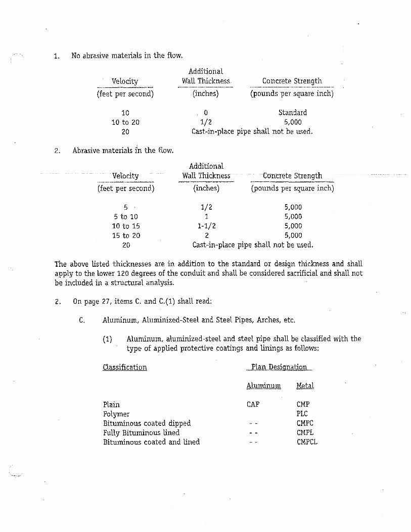
1. No abrasive materials in the flow.
Velocity
(feet per second)
10 10 to 20
20
2. Abrasive materials in the flow.
Velocity
(feet per second)
5 5 to 10
10 to 15 15 to 20
20
Additional Wall Thickness
(inches)
Concrete Strength
(pounds per square inch)
o Standard 1/2 5,000
Cast-in-place pipe shall not be used.
Additional Wall Thickness
(inches)
Concrete Strength
(pounds per square inch)
1/2 5,000 1 5,000
1-1/2 5,000 2 5,000
Cast-in-place pipe shall not be used.
The above listed thicknesses are in addition to the standard or design thickness and shall apply to the lower 120 degrees of the conduit and shall be considered sacrificial and shall not be included in a structural analysis.
2. On page 27, items C. and C.(l) shall read:
C. Aluminum, Aluminized-Steel and Steel Pipes, Arches, etc.
(1) Aluminum, aluminized-steel and steel pipe shall be classified with the type of applied protective coatings and linings as follows:
Classification
Plain Polymer Bituminous coated dipped Fully Bituminous lined Bituminous coated and lined
Plan Designation
Aluminum Metal
CAP CMP PLC CMPC CMPL CMPCL

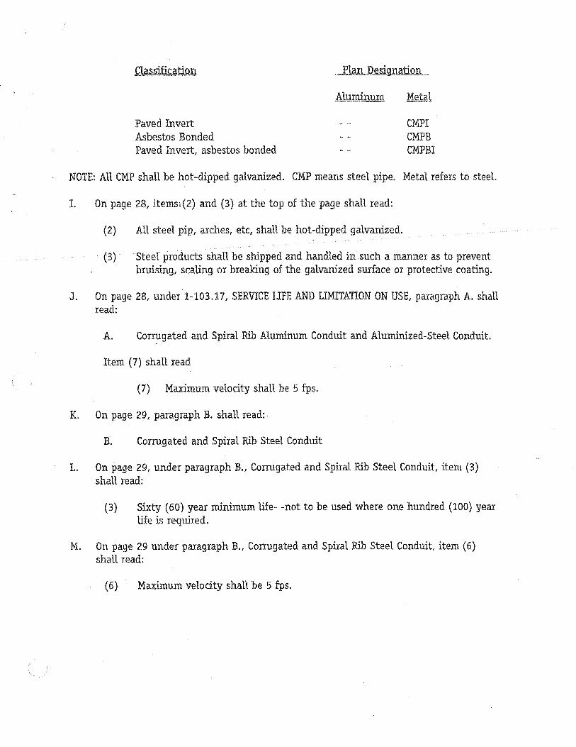
Classification Plan Designation
Paved Invert Asbestos Bonded Paved Invert, asbestos bonded
Aluminum
eMPI CMPB CMPBI
NOTE: AU CMP shall be hot-dipped galvanized. CMP means steel pipe. Metal refers to steel.
1. On page 28, itemsi(2) and (3) at the top of the page shall read:
(2) AU steel pip, arches, etc, shall be hot-dipped galvanized.
(3) Steel products shall be shipped and handled in such a manner as to prevent bruising, scaling or breaking of the galvanized surface or protective coating.
J. On page 28, under 1-103.17, SERVICE LIFE AND LIMITATION ON USE, paragraph A. shall read:
A. Corrugated and Spiral Rib Aluminum Conduit and Aluminized-Steel Conduit.
Item (7) shall read
(7) Maximum velocity shall be 5 fps.
K. On page 29, paragraph B. shaH read:
B. Corrugated and Spiral Rib Steel Conduit
L. On page 29, under paragraph B., Corrugated and Spiral Rib Steel Conduit, item (3) shall read:
(3) Sixty (60) year minimum life- -not to be used where one hundred (100) year life is required.
M. On page 29 under paragraph B., Corrugated and Spiral Rib Steel Conduit, item (6) shall read:
(6) Maximum velocity shall be 5 fps.

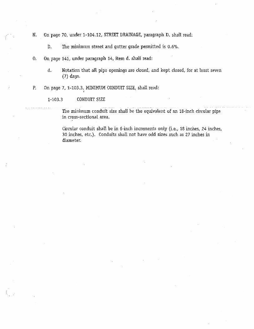
N. On page 70, under 1-104.12, STREET DRAINAGE, paragraph D. shall read:
D. The minimum street and gutter grade permitted is 0.6%.
O. On page 141, under paragraph 14, item d. shall read:
d. Notation that all pipe openings are dosed, and kept dosed, for at least seven (7) days.
P. On page 7, 1-103.3~ MINIMUM CONDmT SIZE, shall read: I
1-103.3 CONDmT SIZE
The minimum conduit size shall be the equivalent of an l8-inch circular pipe in cross-sectional area.
Circular conduit shall be in 6-inch increments only (Le., 18 inches, 24 inches, 30 inches, etc.). Conduits shall not have odd sizes such as 27 inches in diameter.


ACCEPTABLE PRODUCTS
1. Corrugated Polyethylene (CPEP) Pipe
Description - This specification covers the furnishing and placing of corrugated polyethylene storm drain pipe in nominal diameters 18 inches through 36 inches for storm drain projects.
Only CPEP, which has a smooth interior lining providing for increased hydraulics and additional stiffness, will be allowed.
i
Materials Pipe: The pipe and fittings shall be manufactured in accordance with the' following specifications:
AASHTO M-294 latest addition. Minimum stiffness at 5 percent deflection per ASTM D-2412 shall be as follows:
Diameter 18 inches 24 inches 30 inches 36 inches
Stiffness 40 34 28 22
Joints: The pipe shall have split couplings with nylon ties. Neoprene sponge gaskets mounted in the couplings shall be furnished by the pipe manufacturer. Maximum allowable deflection at joints shall be 5 degrees. Other joint systems must be approved by the engineer.
Installation - Corrugated polyethylene pipe may be exposed the rays of the sun.
The minimum allowable trench width is two feet wider than the outside diameter of the pipe, or if a soil! cement slurry is used, the minimum allowable trench width is six inches wider than the outside diameter of the pipe. The pipe shall be centered in the trench.
The minimum allowable cover is 24 inches to finished grade. The maximum allowable cover shall conform to the manufacturer's requirements.
II. Plastic Pipe
Plastic pipe culverts shall be either corrugated smooth-interior high density polyethylene (HDPE), ribbed smooth-interior polyvinyl chloride (PVC) or high density polyethylene (HDPE) smooth-interior pipe.

Corrugated smooth-interior HDPE plastic pipe culverts shall conform to AASHTO Designation M294 and ribbed smooth-interior PVC plastic pipe culverts shall conform to AASHTO Designation F794. The inside diameter and diameter tolerances shall conform to the requirements of AASHTO Designations M294 or F794.
The materials for HDPE pipe and fittings shall be virgin compounds which have a minimum cell classification of either 315412C, 334433C or 335434C and conform with the requirements of ASTM Designation D3350.
The materials for PVC pipe and fittings shall be virgin compounds which have a minimum cell classification of 12364C and conform " with the requirements of ASTM Designation D1784.
III. Reinforced Thermosetting Resin (RTR) Coupling for Concrete Pipe
IV. Precast Cleanouts and Inlets
The design and specifications for these products, polyethylene pipe, plastic pipe, RTR coupling and precast cleanouts and inlets shall be shown and specified on the engineering plans.


Document No.
City of San Diego Drainage Design Manual
April 1984
Mayor
ROGER HEDGECOCK
City Council
BILL MITCHELL BILL CLEATOR GLORIA D. MC COLL WILLIAM D. JONES ED STRUIKSMA MIKE GOTCH DICK MURPHY UV ALDO A. MARTINEZ, JR.
City Attorney
JOHN WITT
City Manager
RAY T. BLAIR, JR.
768917 -----------------
First District Second District Third District . Fourth District Fifth District Sixth District Seventh District Eighth District
Filed in the Office of the City Clerk on ___ A_P_R_I_L_2_0....;.;.......1_98_4 ___ _

CHAIRMAN:
ACKNOWLEDGMENTS
DRAINAGE COMMITTEE
JAMES P. CASEY J.R. CROSBY JOHN RIESS W. G~NE AKIN R.E. CAIN CAL CHONG C.R. LOCHHEAD GEORGE PARKINSON CARL STEFFENS ROBERT FERRIER
U • S. Soil Conservation Service
U. S. Corps of Engineers
U. S. Weather Bureau
CITY ENGINEER DEPUTY DIRECTOR DEPUTY CITY ATTORNEY DEPUTY CITY ENGINEER DEPUTY CITY ENGINEER DEPUTY CITY ENGINEER DEPUTY CITY ENGINEER DEPUTY CITY ENGINEER DEPUTY CITY ENGINEER GENERAL SERVICES DEPARTMENT
State of California Division of Highways (CALTRANS)
State of California Department of Water Resources
Los Angeles County Flood Control District
City of Los Angeles
San Diego County Engineering Department
San Diego County Flood Control District Staff
City of Sacramento
County of Sacramento
Ci ty of El Cajon
City of Carlsbad
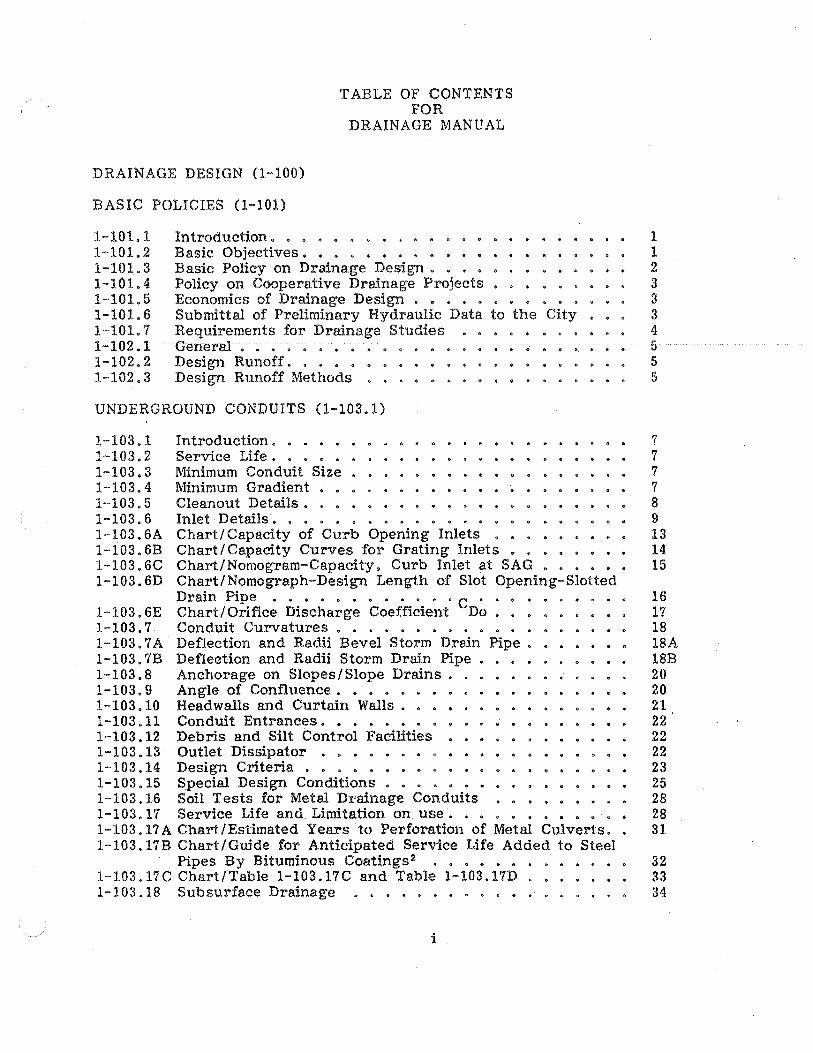
T ABLE OF CONTENTS FOR
DRAINAGE MANUAL
DRAINAGE DESIGN (1-100)
BASIC POLICIES (1-101)
1-101.1 1-101.2 1-101.3 1-101.4 1-101.5 1-101.6 1-101. 7 1-102.1 1-102.2 1-102.3
Introd uction. . • • • . • • • . • • . • •• • • Basic Objectives. • • . • • • • • • . • . . • . Basic Policy on Drainage Design. . • • •• • • • • • Policy on Cooperative Drainage Projects . •.. • • . Economics of Drainage Design . • . • • • • . Submittal of Preliminary Hydraulic Data to the City Requirements for Drainage Studies • • • • . • General Co It • • • • • • • •
Design Runoff. . • • . • • • . Design Runoff Methods • •
lit • Ii
UNDERGROUND CONDUITS (1-103.1)
1-103.1 1-103.2 1-103.3 1-103.4 1-103.5 1-103.6 1-103.6A 1-103.6B 1-103.6C 1-103.6D
Introduction. . . • • . . . • . • • • . Service Life. . . . . . lit .. • • I) • 1/1 •
Minimum Conduit Size • • • . • • • • • Minimum Gradient • . . . . . • • • • • Cleanout Details. • • • Inlet Details. . . • • . . • • . . . . • Chart/ Capacity of Curb Opening Inlets • Chart/ Capacity Curves for Grating Inlets • • Chart/Nomogram-Capacity. Curb Inlet at SAG •••. Chart/Nomograph-Design Length of Slot Opening-Slotted Drain Pipe . . . It e 0 Co • Co Co Co • C e • It •
1-103.6E Chart/Orifice Discharge Coefficient Do •.. 1-103.7 Conduit Curvatures .•...•••••.•. 1-103.7A Deflection and Radii Bevel Storm Drain Pipe. 1-103.7B Deflection and Radii Storm Drain Pipe. 1-103.8 Anchorage on Slopes/Slope Drains. 1-103.9 Angle of Confluence ••••••.••••. 1-103.10 Headwalls and Curtain Walls. • . • . • • . 1-103.11 Conduit Entrances ••.•••.. 1-103.12 Debris and Silt Control Facilities 1-103.13 Outlet Dissipator . • • . • . • • • 1-103.14 Design Criteria • • • • • • . • . • 1-103.15 Special Design Conditions •..••.••. 1-103.16 Soil Tests for Metal Drainage Conduits 1-103.17 Service Life and Limitation on use. • • • • • 1-103.17A Chart/Estimated Years to Perforation of Metal Culverts •• 1-103.17B Chart/Guide for Anticipated Service Life Added to Steel
Pipes By Bituminous Coatings:! . . . . • • 1-103.17C Chart/Table 1-103.17C and Table 1-103.17D . 1-103.18 Subsurface Drainage •..•.•..•.•.
i
1 1 2 3 3 3 4 5 5 5
7 7 7 7 8 9 13 14 15
16 17 18 18A 18B 20 20 21 22 22 22 23 25 28 28 31
32 33 34

T ABLE OF CONTENTS (Continued)
1-103.18AChart/Plan View of Typical Subdrain Layout. 1-103.18B Chart/Typical Subdrain Cross-Section Details .••• 1-103.19 Conduit Designations on the Plans. • • • .• . ••• 1-103.20 Easements .••••.•.••••.•.•••••.• 1-103.2lA Table/Design Values for Mannings Roughness
Coefficient (n) • • • • • • • • • • • • • • • • • 1-103.21B Table/D-Load Requirements Reinforced Concrete Pipe 1-103.21B Table D-Load Requirements Reinforced Concrete Pipe 1-103. 21C Table/Maximum Cover for Corrugated Steel Pipe •.. 1-l03.2lD Table/Maxirrium Cover for Corrugated Steel Pipe 3" X I"
Corrugations . . . 0 " I'll •••• 0 0 • • If) 0 • @ 0- 0 • til
1-103.21E Table/Maximum Cover for Structural Steel Plate Circular Pipe - 6" X 211 Corrugations • • • • • • • •
1-103.21F Table/l-l03.2lF and Table/I-I03.21G ...•••.• 1-103.2IH Table/l-103.21H and Table/lOl03.21I ..•••..••. 1-103.21J Table/Depth and Spacing of Underdrains for various
Soil Types . . . . . . . . e • .. • • .. • .. iii 0 • • (I
1-103.22 Design Guides ...•..••.•..•.••••...• l-103.22A Figure/Typical Plan in Improved Streets (Flat Grades) •• 1-103.22B Figure/Typical Profile in Improved Streets
(Flat Grades) e ., " •••••• e • • • • • • • ••
1-103.22C Figure/Typical Plan in Easement (Steep Grades) ••. 1-103.22D Figure/Typical Profile in Easement (Steep Grades) . 1-103.22E Figure/Typical Plan Combination of Flat and Steep
Grades with Curved alignment and Profile • • • • . • 1-103.22F Figure/Typical Profile Combination of Flat and Steep
Grades with Curved Alignment and Profile. • • • • • . . 1-103. 22G Figure/Typical Plan in Easement with Complex Alignment.
on Fill Slope ... . . . . .. . CI • • • ... • • • • • • • !II
1-103.22H Typical Profile in Easement with Complex Alignment on Fill Slope . . . (II • • • e " & " " • G. " • • • • •
OPEN CHANNELS (1-104)
1-104.1 Introduction ••..•... 1-104.2 Minimum Channel Gradient. 1-104.3 Channel Alignment • . . . . ..• 1-104.4 Channel Superelevation • . • •••••• 1-104.4 Chart/Formulae for Channel Superelevation 1-104.5 Channel Transitions •.••... 1-104.6 Angle of Confluence. . • • • • • • .•. 1-104.7 Cut-off Walls .•••••.•.. 1-104.8 Debris and Silt Control Facilities 1-104.9 Outlet Dissipator • • • • • • • • • • . • • ••.• 1-104.10 Channel Types • • • • • • • • • • • •••• 1-104.l0A Table/Permissable Velocities for Unlined Channels •••• 1-104 .10B Table/Permissable Velocities for Grass-Lined Channels •. 1-104.11 Drainage Ditches . . • . . . • . . . . . . • . • . . • .
ii
37 38 39 40
42 43 44 45
46
47 48 49
50 51 52
53 54 55
56
57
58
59
60 60 60 60 63 64 64 65 65 65 65 67 68 69

TABLE OF CONTENTS (Continued)
1-104.12 Chart/Gutter and Roadway Discharge - Velocity Chart .. 1-104.13 Channel Easements .••••••..•••• 1-104.14 Mannings Roughness coefficient .•.•..•• 1-104.14A Table/Design Values for Mannings Roughness
Coefficient (n) . . • . . . . . . . . . • . . . 1-104.14B Chart/Nomograph for Solution of Manning Equation 1-104.15 Design Guides •••••••••• 1-104-15A Figure/Typical Channel Plan .•. 1-104 .15B Figure/TYljlical Channel Profile
APPENDIX I
Rational Method
APPENDIX II
Modified Rational Method
APPENDIX III
SCS Method.
SEDIMENT DETENTION
Basin Desilting
APPENDIX IV
INDEX
What pH Values Mean • • • • • • • . • . • • • •
Definitions (CALTRANS-Highway Design Manual).
Department Instructionf for C. I. P. C. P. • • • • .
70A 71 73
74 76 77 78 79
80 thru 87
88 thru 92
93 thru 119
120 thru 126
131
132 thru 138
139 thru 142
Index. e 0 • • • • • • & G • e " f/I • 'It • 0 It 0 • • • .. 0 143 thru 146
ill


1-101.1 INTRODUCTION
DRAINAGE DESIGN (1-100)
BASIC POLICIES (1-101)
1-100
The purpose of this section is to provide policies and procedures to attain reasonable standardization of drainage design throughout the City and coordination with procedures of the County and other local jurisdictions. i
Adequate designs for each project should provide for removal of runoff from the roadway or the upstream end of any development. and for carrying runoff water from the upstream side to the downstream side. These functions should be accomplished without causing objectionable backwater. causing excessive or increased velocities, creating damages to downstream ownerships. or unduly affecting the safe operation of traffic on the' road way. Design criteria for drainage should be selected to provide for safe operation of vehicular and pedestrian traffic and to prevent damage to any adjacent property. The goal of drainage design is to provide optimum facilities considering function versus cost. rather than to design facilities that just meet arbitrary minimum standards.
1-101.2 BASIC OBJECTIVES
A. Objectives are to collect. transmit and discharge drainage in a manner to promote public safety and provide for low maintenance by:
(1) Calculating the amount and frequency of storm runoff.
(2) Determining the natural points of concentration and discharge and other hydraulic controls.
(3) Determining the necessity for protection from floating trash and from debris moving under water.
(4) Determining the requirements for energy dissipation and slope protections.
(5) Analyzing the deleterious effects of corrosive soils and waters on drain pipe and structures.
(6) Minimizing scour and siltation of natural stream beds, canyons and lagoons.
(7) Preventing the diversion of drainage.
1
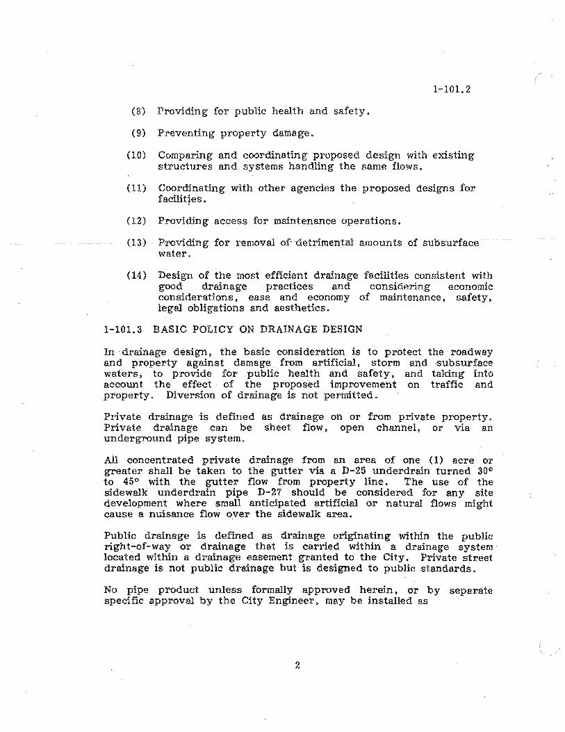
(8) Providing for public health and safety.
(9) Preventing property damage.
1-101.2
(10) Comparing and coordinating proposed design with existing structures and systems handling the same flows.
(11) Coordinating with other agencies the proposed designs for iacilitf€s.
(12) Providing access for maintenance operations.
(13) Providing for removal of detrimental amounts of subsurface water.
(14) Design of the most efficient drainage facilities consistent with good drainage practices and considering economic considerations. ease and economy of maintenance. safety I legal obligations and aesthetics.
1-101. 3 BASIC POLICY ON DRAINAGE DESIGN
In drainage design. the basic consideration is to protect the roadway and property against damage from artificial, storm and ·subsurface waters. to provide for public health and safety, and taking into account the effect of the proposed improvement on traffic and property. Diversion of drainage is not permitted.
Private drainage is defined as drainage on or from private property. Private drainage can be sheet flow. open channel, or via an underground pipe system.
All concentrated private drainage from an area of one (1) acre or greater shall be taken to the gutter via a D-25 underdrain turned 30 0
to 45 0 with the gutter flow from property line. The use of the sidewalk underdrain pipe D-27 should be considered for any site development where small anticipated artificial or natural flows might cause a nuisance flow over the sidewalk area.
Public drainage is defined as drainage originating within the public right:-of-way or drainage that is carried within a drainage system located within a drainage easement granted to the City. Private street drainage is not public drainage but is designed to public standards.
No pipe product unless formally approved herein, or by separate specific approval by the City Engineer, may be installed as
2

1-101.3
a public drain. On occasion, short segments of new pipe products may be used with the specific review and written approval of the City Engineer.
1-101.4 POLICY ON COOPERATIVE DRAINAGE PROJECTS
The City may participate in cooperative projects for storm drains in accordance with Council Policy 800-4.
1-101.5 ECONOMICS OF DRAINAGE DESIGN
A. Economic comparisons of drainage designs. where a choice is available. should consider the following factors:
(1) Initial cost of construction and right-of-way.
(2) Extra ~ost for safety and aesthetics.
(3) Useful life and cost of replacement. lining or extensions.
(4) Cost effects of the facilities on property. such as a reduction in value. and particularly as to protection of City liability for personal injury or property damage.
(5) Cost to the traveling public of any delays or extra travel distance occasioned by road closures.
(6) Maintenance costs for cleaning. repair. traffic control and all other pertinent maintenance costs that may occur during the total life of the facilities.
(7) Justifiable extra costs for access or oversize to allow the use of maintenance equipment.
(8) Inlet and outlet control.
1-101. 6 SUBMITTAL OF PRELIMINARY HYDRAULIC DATA TO THE CITY
Submittal of hydraulic data and preliminary plans for drainage structures to the City are required for approval.
A. Data to be provided with the plans may include:
(1) Hydrology studies, including design Q and frequency.
(2) Hydraulic design studies and reports.
3

(3) Hydraulic and/or energy grade lines.
(4) Inflow-outflow hydrographs.
(5) Stream velocities.
(6) Design water surface profiles.
(7) Slopejprotection limits.
(8) Subsurface investigations.
(9) Specifications, estimates.
1-101.6
(10) HEC II Computer run based on sub critical flow velocities (regardless if actual frequency flow is supercritical) for all projects within the Federal Emergency Management Agency (FEMA) regulation limits and any other one hundred (100) year frequency or greater storm flow requirements.
(11) Any other data necessary for adequate review.
(12) HEC II or FLUVIAL 11 Computer runs where appropriate for bridge construction in a watercourse.
1-101. 7 REQUIREMENTS FOR DRAINAGE STUDIES
A. On-site drainage studies shall be made on 200 scale topo sheets or a scale readable and workable on one sheet. Off-site drainage studies may be made on other scales depending on the drainage area and necessary details for an appropriate and readable study.
B. Drainage studies must include:
(1) Quantity of flow at each inlet or intercepter.
(2) Quantity of flow and direction in street gutters within each street involved in the improvement and off-site as required to completely identify the flow received and discharged from the project.
(3) Topo sheets must show readable contours.
(4) All existing drainage systems involved. with quantity of flow shown.
(5) Entire proposed improvement plotted.
(6) All proposed drainage systems with quantities and velocities shown.
4
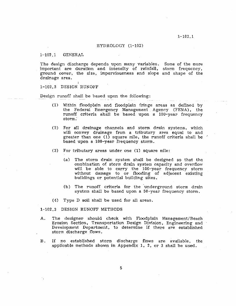
HYDROLOGY (1-102)
1-102.1 GENERAL
The design discharge depends upon many variables. important are duration and intensity of rainfall, ground cover. the size, imperviousness and slope drainage area.
1-102.2 DESIGN RUNOFF
Design runoff shall be based upon the following:
1-102.1
Some of the more storm frequency. and shape of the
(1) Within floodplain and floodplain fringe areas as defined by the Federal Emergency Management Agency (FEMA). the runoff criteria shall be based upon a 100-year frequency storm:
(2) For all drainage channels and storm drain systems. which will convey drainage from a tributary area equal to and greater than one (1) square mile, the runoff criteria shall be based upon a ·100-year frequency storm.
(3) For tributary areas under one (1) square mile:
(a) The storm drain system shall be designed so that the combination of storm drain system capacity and overflow will be able to carry the lOO-year frequency storm without damage to or flooding of adjacent existing buildings or potential building sites.
(b) The runoff criteria for the 'underground storm drain system shall be based upon a 50-year frequency storm.
( 4) Type D soil shall be used for all areas.
1-102.3 DESIGN RUNOFF METHODS
A. The designer should check with Floodplain Management/Beach Erosion Section, Transportation Design Division. Engineering and Development Department. to determine if there are established storm discharge flows.
B. If no established storm discharge flows are available. the applicable methods shown in Appendix I, 2. or 3 shall be used.
5

1-102.3
(1) Storm discharge flows shall be based on:
(a) Watersheds less than 0.5 square mile - Rational Method. See Appendix 1.
(b) Watersheds 0.5 - I square mile - Modified Rational Method. See Appendix 2.
(c) Watersheds greater than 1 square mile - SCS Methods, tabular or computer, or U. S. Army Corps of Engineers - BEC I computer method. See Appendix 3.
(d) Design runoff for drainage and flood control facilities within the City shall be based upon full development of the watershed area in accordance with the land uses shown on the City of San Diego, Progress Guide and General Plan.
(e) When determining criteria for floodplain management and flood proofing, design runoff within the City shall be based upon existing conditions in accordance with the City Floodplain Management Requirements and the Federal Emergency Management Agency (FEMA) Regulations. Under City requirements, the minimum elevation of the finished, first floor elevation of any building is two (2) feet above the IOO-year frequency flood elevation.
6

UNDERGROUND CONDUITS (1-103)
1-103.1 INTRODUCTION
1-103.1
Hydraulics. debris and detritus, maintenance, inlet conditions. outlet conditions. safety, the effects on traffic. property, economics and aesthetics shall be considered in the design of all underground conduits.
1-103.2 SERVICE LIFE
The minimum design service life for all underground conduits shall be sixty (60) years.
A. The service life for underground conduits shall be 100 years when:
(1) The height of cover is in excess of fifteen feet (15').
(2) The conduit is or may be located under a structure or the overhang of a structure.
(3) Located within the traveled way of 4-lane collector, major and prime arterial streets.
(4) Storm drains adjacent to or between structures which are located horizontally a distance equal to or less than the vertical pipe cover depth in feet from the structure to the center line of the pipe.
(5) Any storm drain pipe under a pressure head.
,r)\lt~~~~'lYr~ f} ~ . _ n ./L J -~ .SE AV&l~l'{ tilv\ / C t ~ r
1-103.3 MINIMUM CONDUIT S1iZE~ .. b I r V.Jj S ,ll (' I~ Ie. l ~1',JJ:lJ{M \ ('J\) C
The minimum conduit size shall be the equival~nt of an 1S-inch circular pipe in cross-sectional area.
1-103.4 MINIMUM GRADIENT
The minimum gradient shall be governed by an 0.5 percent grade, or by a minimum velocity of four feet (4') per second with the pipe flowing one quarter full. Flatter grades may be approved where no other practical solution is available. Conduits shall be designed to flow full and free of pressure heads except for short runs where the grade changes and a small pressure head cannot be avoided. Where it is necessary to design for a pressure head in a system and it is approved by the City Engineer, pressure pipe with water-tight joints shall be used (100 year service life).
7

1-103.5
1-103.5 CLEANOUT DETAILS
For purposes of design, the definition of a cleanout under this section shall mean those structures designated as cleanout, curb inlet or catch basin in City of San Diego Standard Drawings.
A. Cleanout Spacing - The maximum length in feet between cleanouts for straight runs of conduit shall be as follows:
(1) Cond~it under an equivalent diameter of 30". approximate maximum spacing of 300 feet.
(2) 30" to 41", 400 feet.
(3) 42" to 59". 600 feet.
(4) 60" and over, 800 feet.
(5) When a private storm drain system changes and becomes public. a cleanout shall be provided at the change to initiate the public system.
B. Cleanouts; Horizontal Curves or Angle Points
(1) Cleanouts should be installed near one end of all horizontal curves in the conduit where possible. and maintain the maximum spacing.
(2) A cleanout shall be installed near one end of a horizontal curve when radius is 100 feet or less.
(3) A cleanout shall be installed at the P. C. C. and lor P. R. C. of curves.
(4) A deanout shall be installed at all horizontal angle points, except a single angle of 100 or less will be permitted between cleanouts provided:
(a) The angle point does not combine a horizontal and vertical curve.
(b) The angle point is located within forty feet (40') of a clean out or outfall.
(c) Abrasive bed load materials, under relatively high velocities (15 F.P.S, or greater) will not occur.
8

1-103.5
C. Cleanouts; Vertical Curves or Angle Points
(1) Normally on sag vertical curves the cleanout should be located at the end connecting the flattest grade.
(2) A cleanout shall be installed at vertical angle points. except a single angle of 10 0 or less will be permitted between cleanouts provided:
i (a) The angle point does not combine a horizontal and
vertical curve.
(b) The angle point is located within ten feet (10') of a cleanout or outfall.
(c) Abrasive bed load materials under relatively high velocities (15 F. P. S. or greater) will not .occur.
(3) An angle of deflection of 300 within ten feet (l0') of an outfall may be approved, provided a factory manufactured elbow (100 max. angle points) is used. Should the conduit ever be extended from this outfall. a cleanout shall be provided at this point. Should the direction of the pipe change more than a total of 30 0 in the vertical or horizontal direction from the top of slope to bottom of slope, a cleanout is required at the bottom angle point.
W:tl~n a pipe size or type is changed. make the change in a ch~ariout or inlet structure.
The design shall make sure that the energy gradient is six inches (6 ") lower than the bottom of the roof slab on a cleanout.
1-103.6 INLET DETAILS
A. Type of inlet to be used when an inlet shall be required as follows:
(1) Type" A" Curb Inlet - May only be used where there is no room behind the curb (due to existing conditions) to accommodate other curb inlets. or will provide the most efficient design for a particular problem.
(2) Type "B" Curb Inlet - To be used as the basic inlet to intercept street drainage.
9

1-103.6
(3) Type "c" Curb Inlet - Not permitted where street grade is less than five percent (5%). May be used to gain additional inlet capacity of two (2) C.F.S. maximum when a Type "B" curb inlet is slightly insufficient and combined with a street grade over five percent (5%).
(4) Type "D" Curb Inlet - Not permitted in the City of San Diego.
(5) Type i "El! curb Inlet approval.
Not permitted without special
(6) Type "F" Catch Basin ~ To be used to intercept surface drainage from ditches or swales outside of traveled ways. Not permitted adjacent to sidewalks, bikeways or trails for public use.
(7) Type "Gil Catch Basin - Not to be used, use Type "I" catch basin.
(8) Type "H" Curb Inlet Not permitted in the public right-of-way (to be used in alleys, parking areas or similar paved areas).
(9) Type "I" Catch Basin - Only to be used under special conditions and with prior approval. May be used in alleys.
(10) Inlet aprons shall be limited to parking lanes only.
(11) Use curb inlet - Type ItJII Median (D-45) for center median inlets (four feet (4') maximum opening L=5' Max.). Do not depress the gutter beyond the lip of the gutter i. e.. not into the driving lane.
(12) Sidewalk Underdrains - Use Type "At! curb outlet (D-25) for 0.5 C.F.S. to 4.0 C.F.S.; sidewalk underdrains(s) D-27 for flows to 0.5 C. F. S. D-26 is not permitted in the City of San Diego.
(13) Minimum inlet opening length is four feet (4'). L = 5'.
(14) Maximum inlet opening length is twenty feet (20'), L = 21'.
(15) All drainage shall be intercepted and collected at superelevated roadway transition sections where concentrated flows are not permitted to cross traveled lanes under the design storm frequency for the street. Median inlets shall be designed and spaced so the lane adjacent to the median (number one lane or fast lane of traffic adjacent to the median) is free from drainage flow for the design storm frequency.
10

1""103.6
(16) At tee intersections. drainage from the terminatin g or side street shall be picked up in an inlet when the street grade exceeds five percent (5%) and for flatter grades when the gutter flow will encroach or overrun the cross gutter.
(17) The basic criteria for storm drain inlet design shall be that any inlet will be sized to accept one hundred percent (100%) of the drainage received without bypass for the design storm frequency required for the system. Storm flows in the public right-of-way should be picked up at subdivision boundaries.
(18) Any wing on an inlet shall be constructed on the upstream side. i
B. Curb inlets under Section 1-103.S Item A may be used at any approved location in the curb on grades up to five percent (5%). Grades in excess of five percent (5%) may necessitate the use of a concrete apron within the parking lane, additional inlets. or other special inlet design as approved by the City Engineer.
C. Inlet ca.pacities may be determined by CHART l-l03.GA, CHART 1-103.6B, and CHART 1-l03.6C.
D. Slotted drain pipe may be used in certain approved, locations or to increase the capacity of curb inlets, justified. providing it meets the following conditions:
select where
(1)
(2)
(3)
(4)
(5)
(6)
(7)
(8)
(9)
Minimum pipe size shall be eighteen inches (18").
Minimum pipe grade shall be five percent ~. () 51 Minimum slot height shall be six inches (6 il
).
Pipe shall be 16 gage or heavier.
Pipe shall conform to the minimum allowable service life for underground conduits (see 1-103.2).
All drain pipes/conduits shall be designed to withstand an H-20 loading.
Maximum length of anyone run of slotted pipe shall be sixty feet (60').
r: ..,. ... ~:...,!'!l. "... '" . ~.' ""!""". • ' ,," ' .... - .' ''':. ,"
The slotted pipe trench shall be backfilled and encased from below the bottom of the pipe with 420·B 2500 concrete to the sub grade of the final surface course of the traveled way.
Length of slotted pipe required may be determined from CHART 1-103.6D and CHART 1-103.SE.
11 .- -
1-103.6
(10) Use of slotted drain pipe should be discouraged in areas of heavy pedestrian traffic. Expanded wire mesh heel guards shall be attached across the top of the open slot when pipe is approved in pedestrian traffic areas.
(11) Slotted drain pipes, shall be used parallel to concrete median barriers for drainage pickup. These shall be collected in a Type I inlet (grate must be anchored).
i (12) A cleanout shall be installed at one end of a run of slotted
drain pipe.
(.13) Hot dipped galvanized protection is required for eMP slotted drain pipe.
E. All inlets shall be designed to make sure that the energy gradient is a minimum of six inches (6") lower than the gutter grade or grate, for grated inlets, whichever is lower.
12

-
CHART 1-103.6 A
i CAPACITY OF CURB OPENING INLETS
ASSUMED 2% CROWN.
Q = 0.7l (A+y)3/2
*A = 0.33
Y = HEIGHT OF WATER AT CURB FACE (0.4' MAXIMUM) REFER TO CHART 1-104.12
l = LENGTH OF CLEAR OPENING OF INLET
*Use A=O when the inlet is adjacent to traffic; i.e., for a Type "JIt median inlet or where the parking lane ;s removed.
,
REV. CITY OF SAN DIEGO - DESIGN GUIDE SHT. NO.
CAPACITY OF CURB OPEiHNG INLETS
13
Q Z 0 to) ..... en ex: le .... .... .... 101..
U is :::) t.:l
aE· >-.... v : c to)
0.:3
1.0 1.0 '0 os
0.8 o~
O. 0:1
0.5
0 0.5.
0.4
1°.3 ~~~~---+-~--~~~
o 1~_~!-:-_~........I~~ ......... -:r0.1 • OJ OJ!5 02 0.:3 .4
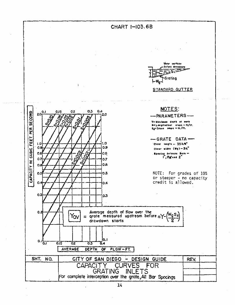
CHART 1-103.69
liANOARO GUTTER
NOTES: ....... PARAMETERS ........ 'e li&nillaa d."~ 61 "rill 801 1. .. ,lt"11III1 @llIlIlI - fl/ft. Ill'" Cnlllll ~. - ft./tt.
-GRATE DATA ......... . e1ur ... ,.a - 35 ~/I. ellUlr "Idtll ('I'lII) - 24"
...... III.lII ~.t.UIi .111"-1",llWtIII~ 2"
NOTE: For grades of 10% or steeper - no capacity credit is allowed.
I AVERAGE DE·Pllt OF FI..OW-FT.
SHT. NO. CITY OF SAN DIEGO ;,.. DESIGN GUIDE REv.
CAPACITY CURVES FOR GRATING INLETS
For cornpleie ~ r:Nef the grate,AlI 80" Spocngs
14

.... "fen w w :t:
W (.)
&I.. Z
~ - -.s::. e .... e e Z S ~ Z Z w I.IJ a.. a.. 0 0
&I.. 1.1.. 0 0
.... :t: ~
/'
REV.
CHART 1-I03.6C
:3
2
~ ~", .. ~ ..
/'" ./ .... y
% .s /~ 14
..J 4~
At"''' i5 ..3
1t~ i-"~ ~ .%
/ ~
£~..qI' ,.-.1
.08
.06
.OS
.04
.03
CITY OF SAN DIEGO - DESIGN GUIDE
NOMOGRAM-CAPACITY. ,CURB INLET AT SAG
15
.9
.13
.7
.6
.5
.4
0 I.IJ 0 Z 0 a.. .3
.• 2
.15
SHT. NO.

CHART 1-103.6D
FOR SLOT ON I ND I CATED GRADE IN CURB AND GUTTER INSTALLATION
EXAMPLE .Ivon: ~.I%
$xzZ
'"" CI 1II5CF$
SOLUTION I.Conn8ct !,,<lInn fi'ol'll 'co !IIRcI Sx 1I!Iin . Ulle to fllrn.", point. ~~ft.et poi'" froM Q to '''''flillg point. lUlItod Mllljuir.cI '8f1gllt -5$: <lCelwlCl1o froM 1\:Iflllulo.
S<;- Longitudinal Slope _%
Sx- Transverse Slope - %
Z -- Transverse Slope Reciproca!-ft./ft. cI - Depfh of Flow - tt. L - Length of Slot - 1t. Q - Discharge - CFS g - Gravity - 32.3 ft.;sec./sec. W-Width afopen Slot (useI.75-:-12ft.) .Coo-- Orifice Discharge CoeffiCient from CHART 1-I03.SE
..J <l: z a ::> .... e z 0 ..J
SHT. NO. CITY OF SAN DIEGO ... DESIGN GUIDE REV.
-0.5
F-2.0
~
I-~O
F-
1=-4.0 F-
r-S.O ~ 1-6.0 ~ ~7.0
NOMOGRAPH- DESIGN LENGTH OF SLOT I----+-------{
OP.ENING - SLOTTED DRAIN PIPE 16
I.S
t-Z w 0 1.0 -~ l.L. w 0 (.)
w C)
a: oct 0.5 --::: (.) (J')
0
0.0
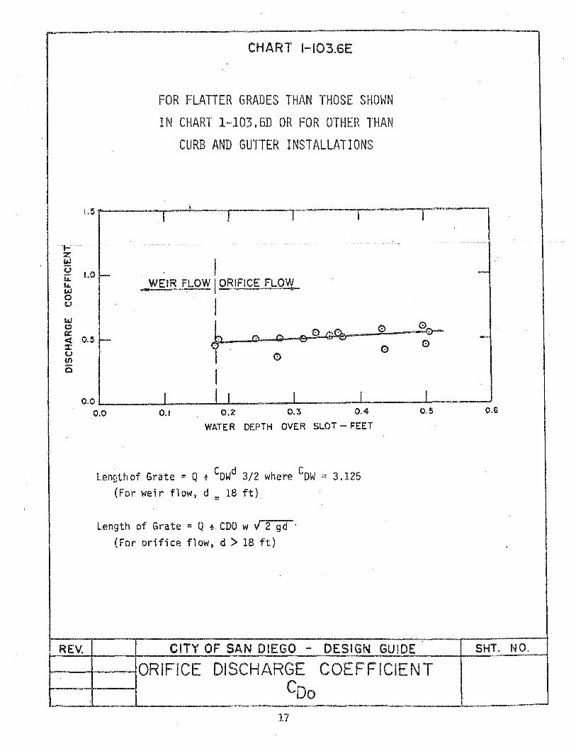
CHART 1-I03.6E
FOR FLATTER GRADES THAN THOSE SHOWN IN CHART 1-103.6D OR FOR OTHER THAN
CURB AND GUTTER INSTALLATIONS
i
I I I I
I .-WEIR FLOW I ORIFICE FLO~
I
f 0 0° 0 % 0' Q
(;) (;)
I I J I I I
0.0 0.1 0.2 0.'3 0.4
REV.
WATER DEPTH OVER SLOT -- FEET
Lengthof Grate = Q + GOWd 3/2 where COW = 3.125 (For weir flow, d = 18 ft)
Length of Grate = Q + COO W V 2 gd . (For orifice flow, d > 18 ft)
CITY OF SAN DIEGO - DESIGN GUIDE
I
0 =-0-
CD
I 0.5
t--............f----+ORJFICE DISCHARGE COEFFICIENT COo
17
-
-
0.6
SHT. NO.
1-103.7
1-103.7 CONDUIT CURVATURES
A. Reinforced Concrete Pipe (R. C • P. )
(1) Horizontal radii . requirements as 1-103.7B.
and deflections shall conform with shown on Table 1-103.7A and
the Table
(2) Verticpl curves shall be circular curves. not parabolic curves and shall be designed so that angle points fall at a pipe joint. Minimum spacing of angle points shall be four feet (4'). Maximum angle at any joint shall be 10°. Vertical deflections shall conform with the deflection requirements as shown on Table 1-103.7A and Table 1-103.7B.
(3) The simultaneous combination of horizontal and vertical curves is not permitted.
(4) Care shall be taken to prevent horizontal and vertical curves within the same run of pipe. Same run of pipe is defined here as any run between two structures or between a structure and the end of the pipe. Should this combination become necessary for a proper design. the proposed design shall be submitted for prior approval by the City Engineer.
(5) RCP installed on slopes over forty percent (40%) shall have water tight joints, reinforced masonry or reinforced cast in place Portland Cement Concrete (PCC) cutoff walls (and velocity rings when required).
B. Asbestos - Cement Pipe (A.C.P.) (This pipe product is not currently readily available.) (1) A. C. P. may be used for relatively straight runs of pipe.
Curves in the alignment shall be of reinforced concrete pipe and shall. be connected with a concrete pipe collar.
(2) If angle points in alignment of A.C.P. are permitted, the maximum angle point permitted will be 100 • The angle point must be a factory-manufactured joint. Any angle point greater than 100 will require a cleanout structure or the use of R. C.P.
(3) Horizontal radii and deflections shall conform with the requirements as shown on Table 1-103.7 A.
(4) The above conditions apply to vertical curves and all angle points.
(5) The simultaneous combination of horizontal and vertical curves is not permitted.
18
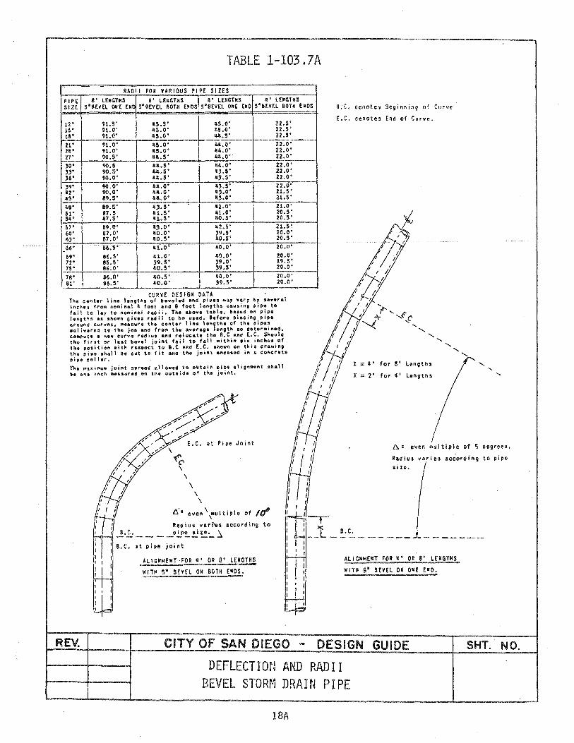
TABLE 1-103.7A
-RADII FOR VARIOUS PIPE SIZES
PIP E S' lE.C:THS S' LOCOTHS &' LEPCTHS .' LENCTHS SIZE S'BEV£L OH EMO S·BEV£L BOTH [M03 S'SEVEL ONE (hO S'SEVEL 80TH EMOS
12" 91.5' 115.5' .5.0' 22.5' 15 ' 91.0' as.o· 15.0' 22.5' 18' 91.0' 115.0' u.S' 22.5'
21" 91.0' 115.0' U.O' 22.0' 2! " 91.0' 115.0' l1li,0' 22.0' 27' 90,S' .U .. S' l1li.0'- 22,0'
,0" 90.5 1111.5 • 114.0' 22.0' ". 90.5' u,5' 11,.5' 22.0' ,6" 90.0' llll.S' 11,.5' 22.0'
,9" 90,0' 1111,0' l,.S' 22.0' liZ" 90,0' 11111.0' .,.0' 21.5' as' e~,5' llll.O· ".C' 21.S'
lie" 89,S' 11,.5' 1I2.0' 21.0' 51" S7,5 al.S' a1.o· 20.5' Sa" 117,5' al.5' 10.5' 20.5'
5Y' 89.0' .,.0' 112.5' 21,S' 60" 87,0' lO.O' '9.5' 20.0' 6,' 87.0' ao.S' 110.5' 20.5'
66" 86.5' 111,0' 110.0' 20.0' 0
69' 86,S' "1.0' llO.O' 20.0' 12" 85,S' ,9.5' '9.0' 19.5' 7," 86,0' ao.s· ,9.5' 20.0'
7S" 86.0' 110.5' 110.0' 20.0' 81' 86.5' 110,0' ;19.5' 20,0'
_ CURVE DESIGN DATA The center line lengths of beyeted 8nd pioe, •• Y v6ry ~y sever.t inches frOM HOMinal l foot and 8 foot lengthS causing pip. to fatl to 14Y to f\of4;nlt.l TacHi. The above table. baaed Oil pcipo l.ngt~s .a shown give. fadii to be vaed. 8.fore placing pi~. arouft~ curve,. M44Iyf. the centor lift. '.A9th. of the pioe. delivered to the job and (ro$ the average length 80 detor.fA.d. eo_owt. & ft •• curve radiYa and r.locate the ft.C aftC E~C. Should the first or It&t bovel joint fail to f411 within lix iftehe. 01 the position with ro,ooet to 6.e &ftd E.C. aho.A on this drawing the pipe sftell be cut to fit afto the joint enea.ed in & concrete I)tP. collar. Tko ~.Xi~UM joint .,road .110wed to Obt4iA pipe align .. ftt BftAl1 'e one inch Measured on the outside of the joiftt.
B.C. cenotes Seginning of Curve
E.C, cenotes End of Curve.
x = ~. for S' LengthS
X ::= 2' for q'
\
"<'e>
at Pipe Joint A: even OIuitiple of 5 cegreH,
Radiul varies according to pipe
REV.
\ \
\ \
\
A': even \multiple of IfII Raaius vari'es according to
..!'.£.: ___ J'!!!"'!!~~ ~ at pipe jOint
ALIGNMENT-FOR q' OR S' LENGTHS
WIT~ 5" SEvEL OM 80TH ("OS.
CITY OF SAN DIEGO
Ii le.
B.C.
ALIGNMENT FOR ~, OR 8' LENGTHS
WITH S· SEVEL ON ONE r"D.
DESIGN GUIDE
DEFLECTIon AND RADI I BEVEL STORM DRAIN PIPE
18A
SHT. NO,

REV.
SIZE INCH
12 15 18
21 2~
'21
30 33 36
118 51 S~
57 60 63
66 69 72
75 7!! 81
811 87 90
93
TABLE 1-103.7B
WAlL INCH
0.0. PIPE INCH
I DEPTH .10 I NT I BELL OPENING ADIUS DEFL. I INCH INCH FEET • _,
16 19 22-1/2
I !lIE
IS/lfi
2-'J/~ 35-1/2 1-3/V. 2-1/8 38-3/11 1-3/q 3-1/13 112-1/11 1-3/~
3-1/2 116 1-7/8 I 3-3ft! 119-1/2 1-1/8 I 3-7/8 52-3/11 1-7/8 I
11-1/ 8 . 56-1/11 2 I 11_1/11 59-1/2 2 I 11-1/2 63 '2 I
11-3/Q 66-1/2 2 I 5 70 2 I 5-1/~ 73-1/2 2 I
3/'4 3/'4 3/11
277 311 3116
2 I~
:2 16 I 55
I 1i0 I 29 I 20
381 I 13 II 17 I 01 11511 I ·01
370 f IS 398 I 10 11211 I OS
1152 I 01 1178 0 58 501 0 55
535 0 52 563 0 II 9 591 0 117
5-1/2 77 2 I 619 0 uS
5-3/11 80-1/2 '2 I I 6q? 0 ~3 Ii Ill! 2-5/8 I 675 0 til
6-1/1! 87-1/2 2-5/8 I 7011 0 39 6-1/2 91 2-5/8 I 731 I) 37
I 6-3/11 911-1/2 2-5/8 I 760 0 35 7 ! 98 2-3/11 I 788 0 311 7-1/11 101-1/2 3 I 816 0 33 7-1/2 lOS 3 I SUII 0 32
7-3/~ 108-1/2 3 1'1 872 031 ~9_6 __ ! __ 8 __ • _____ '_'2 ____ ~3 ____ ~ ______ ~9_0_0~_O __ 30~
~I· rMni .. uliI,l'iPe over 36"
Deflction
Sketch: Joint spread or opened I" fro .. norma'
i--r- 9S·. X -.
___ II- ---0 -r-_
~9S"-1 • _ 192D A - 2RrO
x = opening between pipe in inches
D = 0.0. or 1.0. of pipe in feet (see note)
R = center line radius of curve in feet
Note: If 1.0. of pipe' is used, X wi 11 be opening at inside surface of pipe.
Note: The radius colUMn indicates a Minimum radius for pipe line curves to De laid with straight 8 foot sections of centrifuQal cpnerete pipe. Proportional for" foot pipe sections. For shorter radii. use beveled pipe.
If 0.0. is used, X will be opening of outside surface
CITY OF SAN DIEGO - DESIGN GUIDE SHT. NO.
DEFLECTION AND RADI I STORN DRAIN PI PE
18B

1-103.7
C. Cast-in - Place Concrete Pipe (C. 1. P . C. P. )
The minimum radius of curvature for C. I. P. C. P. shall be thirty (30) times the nominal internal pipe diameter, No Exceptions.
D. Corrugated Aluminum Pipe (C. A. P .) and Corrugated Metal Pipe (C.M.P.) i
(1) The minimum centerline radius for C. A. P. and C. M. P. shall be twenty-five feet (25').
(2) Angle points will be permitted with no one angle point being more than 100 in horizontal or vertical alignment.
(3) Any angle point greater than 10 0 will require a cleanout structure.
( 4) All angles shall be factory manufactured. C . M. P. shall be hot dipped galvanized after factory joint welding.
(5) Horizontal radii and deflections shall conform with the requir.ements as shown on Table 1-103.7 A.
(6) The simultaneous combination of horizontal and vertical curves is not permitted.
E. Corrugated Plate Conduit and Arches
(1) Considered a special design. must have prior approval of the City Engineer. Generally. previous criteria will apply where applicable (100 year service life normally required).
(2) The simultaneous combination of horizontal and vertical curves is not permitted.
F. Rectangular Conduits
(1) Normally a minimum centerline radius of fifty feet (50') shall be used.
(2) The simultaneous combination of horizontal and vertical curves in not permitted. This combination is permitted for reinforced cast in place concrete structures.
19

1-103.7
(3) Masonry structures are not permitted.
1-103.8 ANCHORAGE ON SLOPES/SLOPE DRAINS
A slope drain is defined as a conduit constructed on a grade of 5: 1 (20%) or greater and does not fall within a traveled way. Slope drains are normally located within cut or fill slopes.
A. Slope drains may be permanent installations or temporary drains for a future extension of a permanent installation, above or below
I ground.
B . Any slope drain which would be conspicuous or placed in landscaped areas shall be concealed by burial or other means.
c. In general, slope drains shall have a 100 year service life where slopes are 2-1/2:1 (40%) or steeper.
D. All slope drains shall have positive water-tight joint connections.
E. Slope drain pipe shall conform to the minimum allowable service life for underground conduits. (see 1-103.2).
F. Adequate anchorage or cutoff walls shall be installed at intervals up to a maximum of thirty feet (30') for all conduit pipe placed on or within slopes 3: 1 or steeper. Metal or fiberglass cutoff walls are not permitted.
G. Cutoff walls shall be installed at intervals up to a maximum of thirty feet (30') (horizontally) for all pipes placed in slopes where there is the possibility of erosion of the pipe trench on the slope. Metal or fiberglass cutoff walls are not permitted.
H. All above ground pipes must have special approval and shall be temporary.
I. Reinforced masonry· or reinforced cast in place concrete cutoff walls are required.
1-103.9 ANGLE OF CONFLUENCE
A. In no case shall a component of lateral velocity oppose the mainline velocity by an angle of confluence.
B. The angle of confluence shall be 90 0 or less.
C. The angle of confluence shall be determined by the following:
(1) If the lateral measures an equivalent of thirty-six inches (36") in diameter or more, the angle of confluence shall be 60 0 or less.
20

1-103.9
(2) The change in energy gradient in the cleanout or juncture shall not exceed three feet (3').
(3) In no case shall the energy gradient exceed the elevation of six inches (6") below the gutter grade on inlets» grate for grated inlets, or six inches (6") below the bottom of the roof slab on cleanouts.
D. A concrete lug will be allowed at the junction if: i
(1) The criteria for cleanout locations in both lines is satisfied.
(2) If the connecting pipe is in conformance with the following:
Main Line
24" 27" 301t
36!! 42" 48" 54" or larger
Connector
18t! max. * 18" max. * 21'1 max. * 24" max. 30" max. 301l max. 36" max. **
* A cleanout at that connection will be required if there is no cleanout within fifty feet· (50') of the connection.
** A cleanout will be required when connector pipe exceeds thirty-six inches (36").
(3) That the lug has a maximum depth of cover of fifteen feet (15').
(4) No more than one lug is allowed for a lateral connection in any nominal section length of conduit.
(5) Lugs are only permitted with R.C.P. to R.C.P. or the pipe which is receiving the lugged pipe is R. C. P. or a reinforced concrete box structure. A. C • P. is not permitted to be used in any lug condition.
E. Lugs are not permitted when either pipe is C.LP.C.P.
1-103.10 HEADWALLS AND CURTAIN WALLS
A. Headwalls are to be installed at all inlets and outlets. A curtain wall may be used in place of a headwall where an extension downstream of the conduit is likely to occur prior to the next rainy season and no fill is to be retained at the Wall.
B. Flared end sections may be approved with proper details. if it is unlikely the conduit will be extended in the near future.
21
1-103.10
C. Perimeter fences may be required at the inlet and outlet ends of the conduit to reduce hazardous conditions at such points. To provide for maintenance, access gates may be required in the perimeter fences.
D. Out falls may require energy dissipators. the minimum allowed shall be per Standard Drawing D-40.
1-103.11 CONDUIT ENTRANCES
A. Entrances ishal1 be rounded. beveled or expanded, whichever is appropriate. to increase the capacity of the conduit. whether the outlet is free or submerged and whether the slope is above or below critical.
B. Flared inlets should be considered for efficient design when the conduit flows under inlet control. except When extension of the conduit upstream is imminent.
C. Inlet aprons shall be used as transitions between the conduit and an improved approach channel. and may be used between the conduit and a natural approach channel. These should be designed to prevent grade cutting of natural channels and/or to provide for a more efficient entrance condition.
1-103.12 DEBRIS AND SILT CONTROL FACILITIES
A. Where flows are likely to carry floating debris or rock in sufficient size to block or obstruct the conduit/channel inlet/entrance. a trash fence/rack. or deflector is required. Vehicular maintenance access is also required. These facilities shall be constructed upstream of the inlet! entrance so they will not obstruct the entrance.
B. Should drainage flows be transporting silt. a temporary desilting basin shall be required to prevent silting of the conduit or the area downstream from the conduit or project. (See an example of a desilting basin in the Appendix). These basins are to be maintained by the developer.
1-103.13 OUTLET DISSIPATOR
A. Where conduits discharge into an unimproved or natural channel, and the quantities and velocities exceed those permissable for the material involved. a suitable energy dissipator is to be installed to reduce diSCharge to non-erodable velocities.
B. Drop manholes or cleanouts shall not be used for energy dissipators unless. for a special condition. a special structural design is approved. These should be very rare installations.
22

1-103.14
1-103.14 DESIGN CRITERIA
A. Cast-in-Place concrete pipe shall not be used in streets with existing underground utilities. such as existing water services t sewer laterals. gas services. underground electric services» etc.
B. Only metal pipe shall be used for above ground installations when required for downdrains.
C. Minimum D-Loads (H-20 Loading): i
Reinforced Concrete Pipe
Asbestos Cement Pipe
Cast-in-Place Concrete Pipe
Other Classifications
1350-D*
2000-D**
Requires Special Design**
H-20 Loading**
,*Lateral loading on the pipe will require special circular reinforcing.
**R.C.P. shall be used for all pipes with, or having the potential of, having lateral loads.
D. No conduit shall be reduced in cross-sectional area downstream in any storm drain system.
E. Where the conduit size increases downstream in storm drain systems, the inside top slopes of the conduits shall be continuous in elevation. rather than the flow lines. Change in conduit sizes shall be accomplished in a reinforced concrete storm drain cleanout structure only.
F. All pipes/conduits on a grade of twenty percent (20%) or greater shall have water-tight joints.
G. All pipes/conduits in the storm drain system shall have D-loads or gauge thickness for metal pipes. as appropriate. and shall be indicated in the profiles on the plans. C. I. P. C. P. shall show the wall thickness.
H. Quantities of flow shall be shown in the profile of the conduit at all entrances and pipe runs. and quantities with storm frequency noted and velocities of flow at all outfalls. Outfalls of pipes 1 culverts and ditches, including brow ditches. must show the quantity of flow ffQ" and velocity "Vff on the plans. The velocity shall be calculated in the steeper reach; i. e.. not in the short pipe segment adjacent to an outfall unless backwater curves for the outfall are submitted for the pipe flowing. 1/4,1/2,3/4 and full. The outfall shall be designed for the greatest flow and velocity of the four noted conditions.
23

1-103-14
1. Storm drain stationing shall run upgrade from the lower end of the drain. When a storm drain runs longitudinally in a street, the stationing may be the street stationing.
J. Storm drain out falls shall extend to the nearest well-defined natural drainage channel which can adequately convey the discharge. Downstream conditions shall be investigated to verify the appropriateness of the point of discharge. This may require offsite storm drains or channel stabilization measures.
K. All outfalls from a sump condition in the public right-of-way which cros~ through private property via a drainage easement to the storm drain outfall shall be designed to convey a 100-year frequency storm.
L. When the pipe is expected to carry a large amount of abrasive material, such as rocks and boulders, a special design to protect the full length of invert area (the lower 900 ) and walls within curves to the spring line will be required.
M. Drainage must be picked up prior to reversing superelevation sections to prevent cross flows from one side of the street to the other or median.
N. Storm drains shall not be constructed parallel to and within the slope face. Provide a flat access area over all public storm drains. All storm drains within the slope shall be aligned perpendicular to all slope faces.
O. Storm drains shall be limited to a maximum cover depth of fifteen feet (15'). Approval of the City Engineer is required for drains with more than fifteen feet (15!) of cover.
P. Drainage alignment priority shall be given to the larger of any two connecting storm drain systems. All pipes larger than thirty-six inche s (36") shall not run in to an d out of storm drain inlets in lieu of cleanouts without a specially designed inlet structure. This should be avoided whenever possible.
Q. Cross gutters are not permitted across any four-lane collector, major or prime arterial roadways. or at signalized intersections.
R. Provide the hydraulic calculations when the flow changes from supercritical to subcritical flow.
S. Storm drains with twenty-five feet (25') of cover or more shall meet the following requirements:
(1) lOO-year minimum life.
(2) Sized to allow a future metal plate liner installation which will carry the design storm and retain full structural strength.
24
1-103.14
(3) Pipe runs shall be straight -- no curves or angle points.
(4) Depth of cover over fifteen feet (15') shall be allowed by necessity only. All drains shall utilize every possible means to minimize excessive cover. This may require off site reconstruction or filling of upstream low areas. Larger pipe sizes to reduce pipe depth shall be used.
T. A metal band coupling connection of CMP to CAP or CAP to CMP is not permitted.
U. Diversion of drainage is not permitted. i
V. All landscaped medians shall have storm drain systems which prevent storm and irrigation water from entering the paved roadway. These median drains are to be maintained by the same entity charged with median maintenance. A Portland Cement Concrete paved area on both sides of the landscaped median is required for a maintenance access area.
W. The 50 year frequency storm shall be contained between the curbs (within the public right-of-way) with maximum flows permitted in the curb/gutter controlled by Chart 1-104.12.
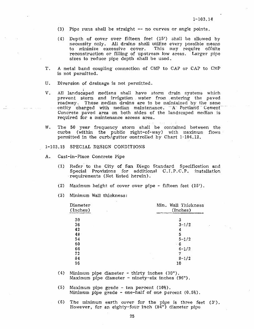
1-103.15 SPECIAL DESIGN CONDITIONS
A. Cast-in-Place Concrete Pipe
(1) Refer to the City of San Diego Standard Specification and Special Provisions for additional C. I. P. C. P. installation requirements (Not listed herein).
(2) Maximum height of cover over pipe - fifteen feet (15').
(3) Minimum Wall thickness:
Diameter (Inches)
30 36 42 48 54 60 66 72 84 96
Min. Wall Thickness (Inches)
3 3-1/2 4 5 5-1/2 6 6-1/2 7 8-1/2
10
(4) Minimum pipe diameter - thirty inches (30"). Maximum pipe diameter - ninety-six inches (96!!).
(5) Maximum pipe grade - ten percent (10%). Minimum pipe grade - one-half of one percent (0.5%).
(6) The minimum earth cover for the pipe is three feet (3'). However, for an eighty-four inch (84") diameter pipe
25

1-103.15
constructed under a traveled roadway. it must have a minimum earth cover of four feet (4'), and for a ninety-six inch (96") diameter pipe under a traveled roadway it must have a minimum earth cover of five feet (5').
(7) Minimum width of undisturbed ground between trenches of other utilities, existing and proposed. and the cast-in-place pipe trench shall be five feet (5').
(8) Construction plans shall show normal pipe dimensions plus the m~nimum pipe wall thickne.ss.
(9) Where cast-in-place pipe crosses over an existing utility. R. C. P. will be required for the pipe crossing as shown on the plans.
(10) Lugs are not permitted in C.I.P.C.P. A cleanout, inlet or similar type of, reinforced concrete structure must be used for a ·storm drain connection or lateral connection.
The following specification requirements shall be adheard to during the design and installation of a C. I. P. C. P • storm drain and the Department Instruction 3930-002 in the appendix:
10 The material in which the pipe is to be constructed must be stable and unyielding when saturated.
II 0 . A Soils Engineer shall verify that the material in which the pipe is to be constructed must be able to stand vertically from the bottom of the trench to three feet (3') above the top of the pipe without sloughing.
III. C . I. P;. C • P. will be permitted for use only in materials which are at a minimum relative compaction of ninety percent (90%).
IV 0 Where structures are to be constructed in the drain. the pipe shall be constructed continuous through the structure location, then cut away while the concrete is fresh to the neat inside lines of the structure. No structure is to be supported by the pipe. Standard reinforced concrete structures are required of cast-in-place concrete pipe.
V 0 C. I. P. C. Po requires a minimum 28-day concrete strength of 4,000 pos.i.
VI. No backf'Ill of C.I.P.C.P. is permitted until 4,000 p.s.i. strength has been verified by laboratory tests.
VII. C. I. P. C. P . repaired sections shall utilize R. C. P. with an appropriate D-load design.
VIII. A Soils Engineer shall certify that the water table in the trench (es) is below the bottom of the trench. or that the trench
26

1-103.15
can be adequately dewatered to allow construction and curing and that the water table maximum elevation is low enough to preclude future damage to the C. I. P. C. P. Storm water shall not enter the pipe until the 28 day strength is :reached and the trench is backfilled.
IX. The removal of concrete to bring high points to flow line grade shall be permitted providing the minimum wall thickness is maintained ..
B. Asbestos-Cement Pipe
(1) Maximum height of cover over pipe - fifteen feet (15 1).
minimum cover - three feet (3').
(2) Couplings shall be asbestos cement sleeves with two sealing rings suitable for connecting lengths of pipe. couplings shall be specified on the construction plans.
C. Aluminum and Metal Pipes. Arches. etc.
(2) The
(1) Corrugated aluminum pipe and corrugated metal pipe shall be classified in accordance with the type of applied protective coatings and linings as follows:
Classification
Plain
Bituminous coated dipped
Fully Bituminous lined
Bituminous coated and lined
Paved Invert
Asbestos Bonded
Paved Invert, Asbestos Bonded
Aluminum
CAP
* All CMP shall be Hot-Dipped Galvanized.
27
Plan Designation
Metal*
CMP
CMPC
CMPL
CMPCL
CMP!
CMPB
CMPBI
1-103.15
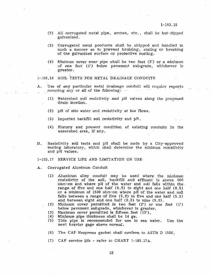
(2) All corrugated metal pipe, arches, etc., shall be hot-dipped galvanized.
(3) Corrugated metal products shall be shipped and handled in such a manner as to prevent bruising, scaling or breaking of the galvanized surface or protective coating.
(4) Minimum cover over pipe shall be two feet (2') or a minimum of one foot (1') below pavement sub grade. whichever is greater.
i 1-103.16 SOIL TESTS FOR METAL DRAINAGE CONDUITS
A. Use of any particular metal drainage conduit will require reports covering any or all of the following:
(1) Watershed soil resistivity and pH valves along the proposed drain location.
(2) pH of site water and resistivity at low flows.
(3) Imported backfill soil resistivity and pH.
(4) History and present condition of existing conduits in the watershed area. if any.
B. Resistivity soil tests and pH shall be made by a City-approved testing laboratory, which shall determine the minimum resistivity and pH values.
1-103.17 SERVICE LIFE AND LIMITATION ON USE
A. Corrugated Aluminum Conduit
(1) Aluminum alloy conduit may be used where the minimum resistivity of the soil, backfill and effluent is above 500 ohm-cm and where pH of the water and soil falls within the range of five and one half (5.5) to eight and one half (8.5) or a minimum of 1500 ohm-em where pH of the water and soil falls between a range of five (5.0) to five and one half (5.5) and between eight and one half (8.5) to nine (9.0).
(2) Minimum cover permitted is two feet (2') or one foot (1') below pavement sub grade , whichever is greater.
(3) Maximum cover permitted is fifteen feet (15'). (4) Minimum pipe thickness shall be 14 gao (5) This pipe is recommended for use in sea water. Use the
next heavier gage above normal.
(6) The CAP Neopreme gasket shall conform to ASTM D 1506.
(7) CAP service life - refer to CHART 1-103.17A.
28
1-103.17
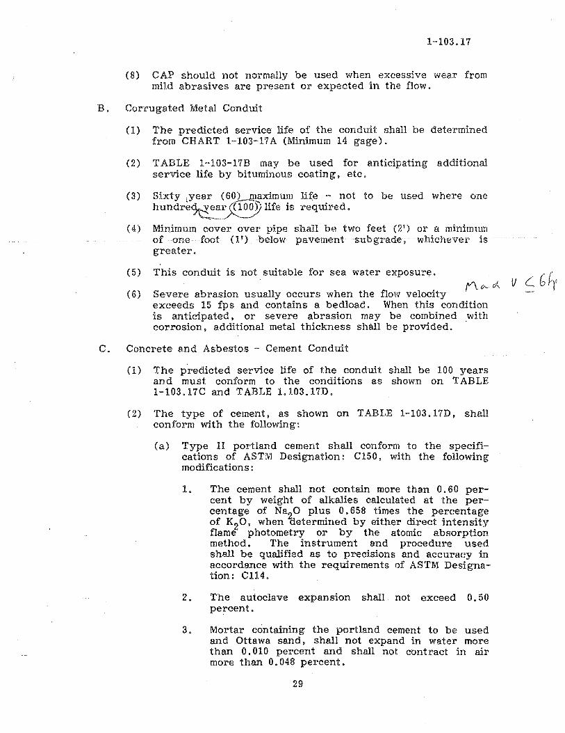
(8) CAP should not normally be used when excessive wear from mild abrasives are present or expected in the flow.
B. Corrugated Metal Conduit
0)
(2)
(3)
(4)
(5)
(6)
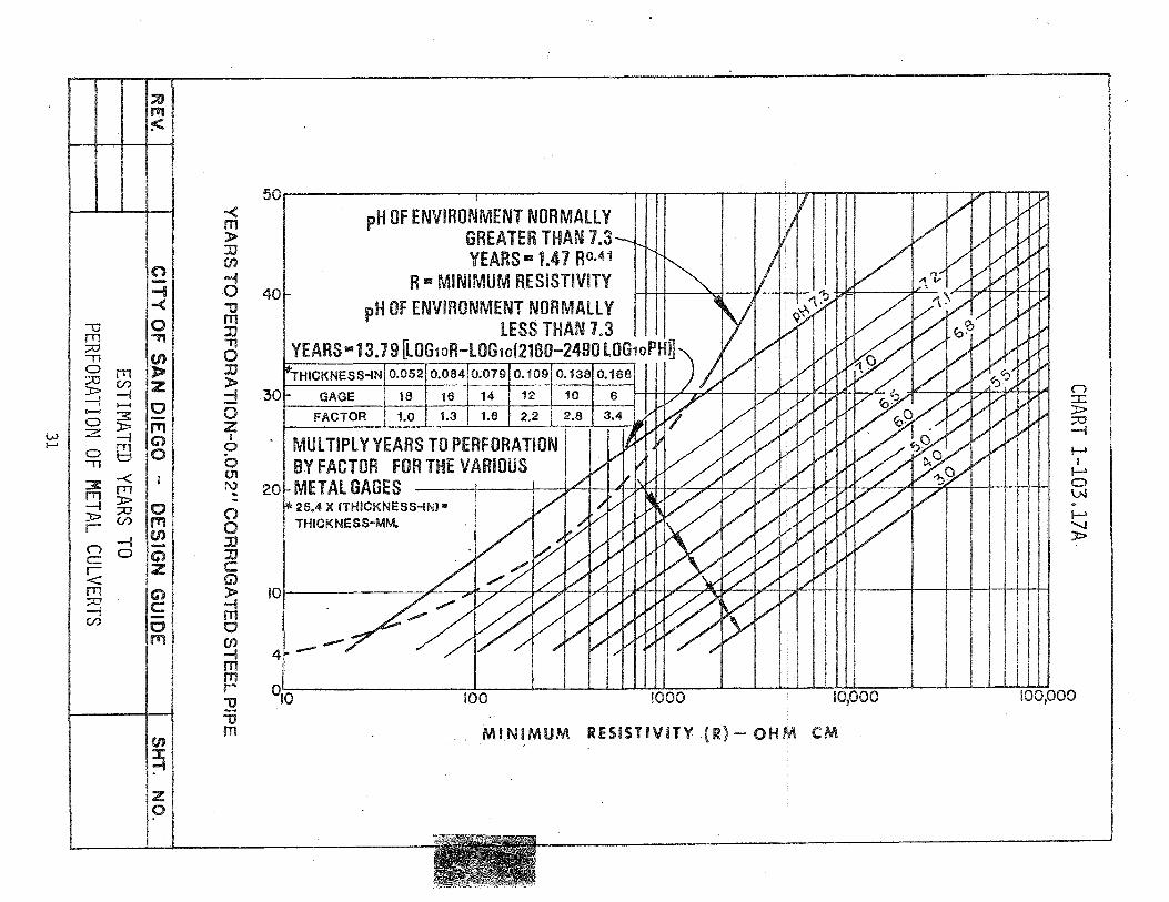
The predicted service life of the conduit shall be determined from CHART 1-103-17A (Minimum 14 gage).
TABLE 1-103-17B may be used for anticipating additional service life by bituminous coating. etc.
Sixty jyear (60) maximum life - not to be used where one hundre~~~ life is required.
Minimum cover over pipe shall be two feet (2') or a minimum of one foot (1') below pavement sub grade , whichever is greater.
This conduit is not suitable for sea water exposure.
Severe abrasion usually occurs when the flow velocity exceeds 15 fps and contains a bedload. When this condition is anticipated. or severe abrasion may be combined with corrosion. additional metal thickness shall be provided.
C. Concrete and Asbestos - Cement Conduit
(1) The predicted service life of the conduit shall be 100 years and must conform to the conditions as shown on TABLE 1-103.l7C and TABLE 1.103.17D.
(2) The type of cement, as shown on TABLE l-103.17D, shall conform with the following:
(a) Type II portland cement shall conform to the specifications of ASTM Designation: Cl50. with the following modifications:
1. The cement shall not contain more than 0.60 percent by weight of alkalies calculated at the percentage of Na20 plus 0.658 times the percentage of K20. when Cietermined by either direct intensity flame photometry or by the atomic absorption method. The instrument and procedure used shall be qualified as to precisions and accuracy in accordance with the requirements of ASTM Designation: C1l4.
2. The autoclave expansion shall not exceed 0.50 percent.
3. Mortar containing the portland cement to be used and Ottawa sand. shall not expand in water more than 0.010 percent and shall not contract in air more than 0.048 percent.
29
1-103.17
(b) Type V Portland cement shall conform to the specification in ASTM Designation: C150, and the modifications listed above for Type II portland cement.
(3) Soluble sulphate content of proposed backflll, watershed soil or runoff. This information shall be submitted to the City Engineer in all instances when the soil resistivity measures less than 3000 ohm-em.
30
W I-'
;u 1"1 :<
(') --i -< o -U "TI rn
:::0 (I)
~ rn » :;.0 C/) Z »-1
0 -1 >-4
.......... 3 -o » ", z -1 Q o ~ 0 -n
-< 3: rn rn » -1 :::0 » C/) r
-1 (") 0 C
~ rn ~ C/)
C) C
o r11
en ~ z o
-< m » JJ (J)
-i o "0 m JJ
" o JJ » ::! o Z I
o o U1 I\) .. () o JJ JJ C G) » -I m o (J) -I m m r "0 "0 m
50~------------~------------~~--~--~~~~~--~~~~~'"
40
pH OF ENVIRONMENT NORMAllY GREATER THAN 1.3 YEARS III! 1.41 R0.41
R 113 MINIMUM RESISTIVITY pH OF ENVIRONMENT NORMAllY
lESS THAN 7.3 YEARS"" 13.79 [lOG10R-lOGwf2160-2490 lOG10PHU
HICKNESS-IN 0.052 0.064 0;019 0.109 0.138 0.168
30 GAGE 18 H3 14 12 10 6 g FACTOR 1.0 1.3 1.6 2.2 2.6 ~
-1 MUl TIPl Y YEARS TO PERFORATION I-'
BY FACTOR FOR THE VARIOUS ~ 20~METAlGAGES ~ '* 25.4 X (THICKNESS-IN) II •
THICKNESS-MM. ~ ):>
IOl 4~--~ 0'0 100 1000 10,000 100,000
MINIMUM RESiSTIVITY (R) - OHM C

TABLE 1-103.17B
-- -"
CMPC! CMPC'''" PROBABL.E
CMPBCI!!i Fl.Ow vn.OCITY I ClIO cAPe!
CAPCI4
ENVIRONMENT
,1iI0U!U.[ SI.OI"II: CliANNE~ 1..0(:£1'10lIl OF CMAlililfl:l. (FEET pm SECON!:) MATERIALS (YEARS) (YEARS) (YEARS)
L.tSS TitAN S ... IIItUIy! S !~ 20
IIIOM A.I\A~IW e IS 20
5- 1 (INCl.) A.IltA!1V1I: 6 12 20
110111 AllieUSIYI: 8 IS 20
MII!:A"I'll'l THAN ., UIt,UIIY\I: 0 5 a
NOIII A III IU.511 Y£ 2 10 20
-NOTES-
1. Channel Materials: If there is no existing culvert, it may be assumed tha.t channel is potentially abrasive to culvert if sand and/or rocks are present;,.
Presence of silt, clay, or heavy vegetation may indica.te a non abrasive flow.
For continuous flow, the years of invert protection can be expected to be one-half of that shown.
2. Any bituminous coating may add up to 20 years of service on the backfill side of. the culvert.
3. CMPC .. :l3i tuminous coating. 4.. CMPCI .. :8i tuminous coating and paved invert.
s. CMPBC:r - Asbestos bonded, bi tum.inous coating and paved invert.
SHT. NO. CITY OF SAN DIEGO ... DESIGN GUIDE
GUIDE FOR ANTICIPATED SERVICE UFE ADDED TO . 5TE.E L PIPES
BY BITUMINOUS COATINGSZ
32
REV.
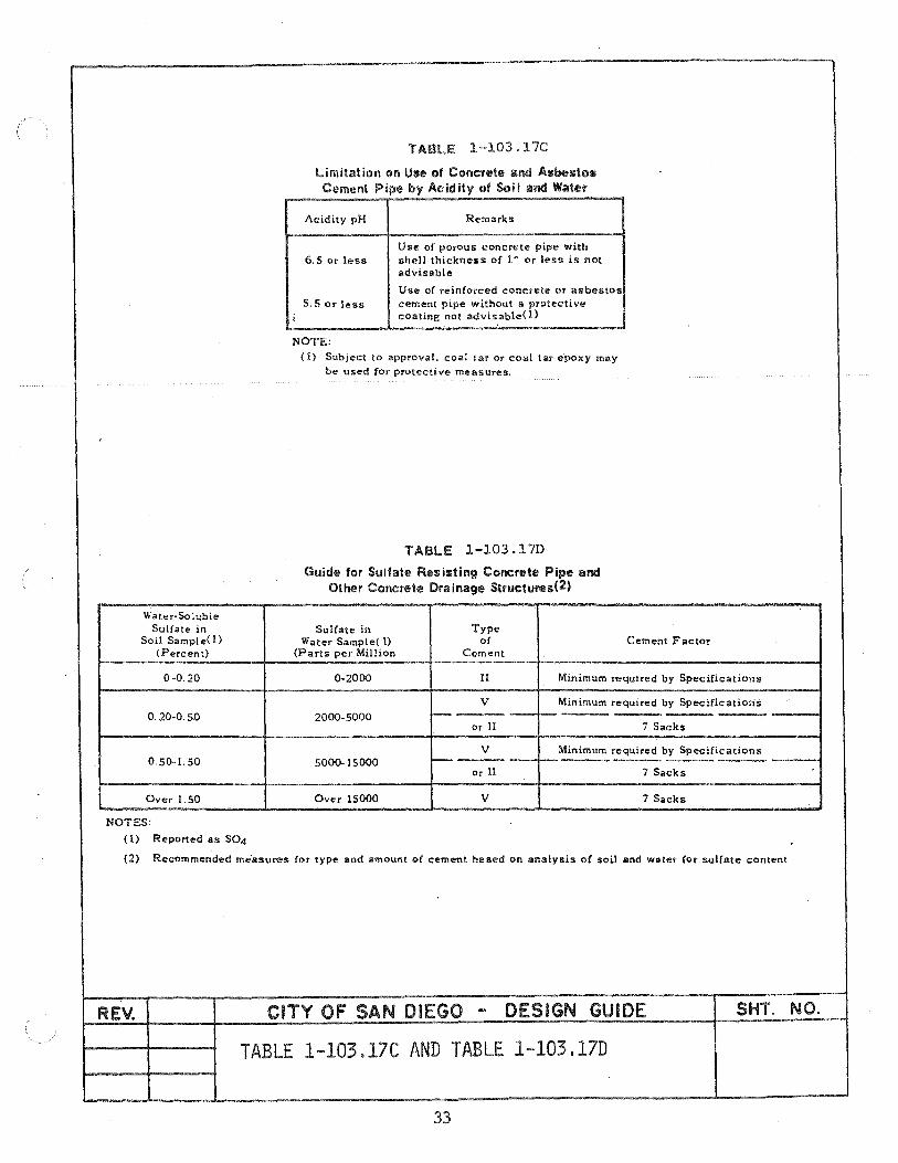
TABLE 1-103.17C
limitation on Use of Concrete and ASDestcue Cement Pipe by ACidity of Soil and Water
Acidity pH Remarks
Use of pOrous concrete pipe with 6.5 or less shell thickness of 1" or less is not
advisable
Use of reinforced concrete or asbestos 5.5 or less cement pipe without a protective
i coating not advisable(i)
NOTE: (l) Subject to approval. coal tar or coal tar epoxy may
be used for protective measures.
TABLE 1-103.17D
Guide for Sulfate Resisting Concrete Pipe and Other Concrete Drainage Stn..lctufes(2)
Wat"r-SoJubJe Sulfate in Sulfate in Type
Soil Sample(l) Water Sample( 1) of Cement Factor (Percent) (Parts per Million Cement
0-0.20 0-2000 II Minimum required by Specifications
V Minimum required by Specifications 0.20-0.50 2000-5000 -
or II i Sacks
V Minimum required by Specifications 0.50-1. SO 5000-15000 ~
Or II 7 Sacks
Over 1. SO Over 15000 V i Sacks
NOTES:
(1) Reported as S04
(2) Recommended me'asures (or type and amount of cement based on analysis of soil and water for sulCate content
REV. CITY OF SAN DIEGO - DESIGN GUIDE SHT. NO.
TABLE 1-103.17C AND TABLE 1-103.17D
33

1-103-18
1-103.18 SUBSURFACE DRAINAGE
A. Seepage Collector Lines
(1) When there is a local seepage problem in an established neighborhood. City will provide a seepage line (pending fund availability) in the public right-of-way to convey seepage away from the private property, provided the property owner.(s) install(s) an acceptable underground drain system on their property to the point of connection in the public right of way (Refer to 1-103.18A). These seepage lines shall be in conformance with Council Policy 800-4.
(2) The minimum size of a seepage collector line within the public right-of-way shall be eight inches (8").
(3) Allowable alternate conduit for seepage collector lines within a public right-of-way shall be asbestos-cement pipe. polyvinyl chloride pipe. acrylonitrile - butadiene - styrene (ABS) composite pipe per ASTM designation: D 2680 (couplings to be Type SC). or vitrified clay pipe.
(4) A suitable cleanout or manhole shall be located in the seepage collector line on a 350 foot spacing for straight runs of pipe. and at each break in alignment or grade.
(5) All seepage lines and sump pump discharge outlets for new construction on existing lots or newly developed lots shall be taken to the nearest existing underground public storm drain system at the property owners expense.
B. Subsurface Drainage
(1) Refer to the City's Geotechnical Guidelines Manual
(2) When required:
(a) Cut and fill slopes shall be provided with approved subsurface drainage as necessary for stability and protection of adjacent properties from the influence of groundwater. The design of such facilities shall be contained in the approved initial pre-grading geotechnical report and/or shall appear on the approved grading plan pursuant to the approval of the Soils Engineer and/or the Engineering Geologist.
34

1-103-18
(b) Specifically, subsurface drainage facilities shall be installed where natural and/or artificially introduced groundwater (Le., derived from meteroic and/or landscape irrigation and similar sources, respectively), affects or is likely to affect the project in a potentially unstable, hazardous or otherwise deleterious manner.
(3) Seepage Statement in Soil Reports and Geological Reports
(a) An Soils Reports and Geological reports submitted for development shall have a statement about the possibility of ground water seepage. This statement shall contain the following items:
1. Sufficient geologic mapping of graded areas to evaluate and comment on anticipated ground water con di tion s .
2. Location of any springs or seeps.
3. Permeability characteristics of on-site earth materials.
4. Subgrade flow along natural drainage proposed for fillings.
(b) In addition, in those developments where seepage has been identified as a possible problem, the final compaction reports submitted to the City shall contain a discussion of geologic conditions encountered during the grading operation as they relate to the ground water regime of the project and mitigative steps taken to prevent ground water build-up.
(4) The minimum size for subsurface drains shall be four inch ( 4") diameter pipe unless otherwise specified by the Soils Engineer.
(5) Surface drainage will not be permitted to discharge into a subsurface drain. The discharge from a subsurface drain into a storm drain will be permitted if the subsurface drain outfall is not under hydrostatic pressure.
(6) Cleanouts. Location and spacing as specified by the Soils Engineer or as required by the City Engineer.
35

1-103.18
(7) Grade Requirements. In general, the minimum allowable grade shall be 0.5 percent. If conditions require flatter grades, approval of the plan by the City Engineer is required.
(8) Depth and spacing of Underdrains: The depth of the underdrain will depend upon the permeability of the soil, the elevation of the water table, and the amount of drawdown needed to insure stability. Whenever practicable. an underdrain i pipe should be set in the impervious zone below the aquifer.
(9) Allowable alternate conduit for subsurface drains shall be perforated asbestos-cement pipe, perforated aluminum pipe. perforated clay pipe. acrylonitrile - butadiene - styrene CABS) composite sewer pipe or perforated polyvinyl chloride pipe.
(10) Subsurface drains shall be carried to a public storm drain system or to a natural well defined drainage channel. Subsurface drains are not permitted to be outfalled into the gutter.
(11) Sump pumps and well points must be discharged in the same manner as stated in (10) above.
(12) Details:
FIGURE 1-l03.l8A Plan View of Typical Sub drain Layout
FIGURE l-103.18B Typical Subdrain Cross-Section Details
36

REV.
FIGURE 1-I03.ISA
r-;,~< D ~D--D . .
HOTE: It grade minimum necessary for proper drain~ge. DirectiOl'l of flow alnd loc::~t ion of discharge point
dependent on ~onfigur~tion ~nd ~lope of lot. t)
STRUCTURE
SlREET
CITY OF SAN DIEGO ... DESIGN GUIDE
PLAN VIEW OF TYPICAL SUBDRAIN LAYOUT
37
SIOEYt.P.O SLOPE
,,' B
SHT. NO.
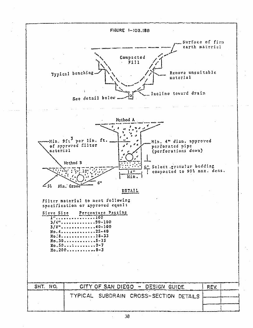
FIGURE 1-103.188
Comp:u:ted fill
-L
Surf:u::e of fir!:1 ca.rth m~ t c1"i;:11
Re~ove unsuit~blc 10101 te Th 1
Kin. 4" dl~Q. ~pprovcd perforated pipe (perforations down)
__ _ _ __ _ '""II -- - - - -- - - .', eo: : : :-:: (i" S e1 e c: t .1: T' :l nul AT' bed din 1: 6 • , • I II .. ' , fIJ' .. , 1 S .. ' " I ,.., T d t t"t 0 • "" <11\ ... ...J lAo n .. "I • ~61 . · /0, I L--=-~--il c:cH:!pac:tc: 0., ~ .......... IJ .. ~ • • "'c I I • J # ....
L I I. .J a.-
I. I .
, , 6" S~ J.Jin: CI':ld~
DET;..IL
FilteT ~:terial to meet followin~ ~pcc:irlc:=tion or approved equAl:
1" ••••••••••••••• 100 3/'" ••••••••••••• ~O-lOO 3/S" ••••••••••••• 40-100 No.4 ••••••••••••• 2S·40 No:S ••••••••••••• lS-ll No.lO •••••••••••• S-1S No.50 •••••••••••• 0·, No.200 ••••••••• ~.O·3
SHT. NO. CITY OF SAN DIEGO ... DESiGN GUIDE REV. I TYPICAL SU8DRAIN CROSS- SECTION DETAILS 1---+---;
38
1-103-19
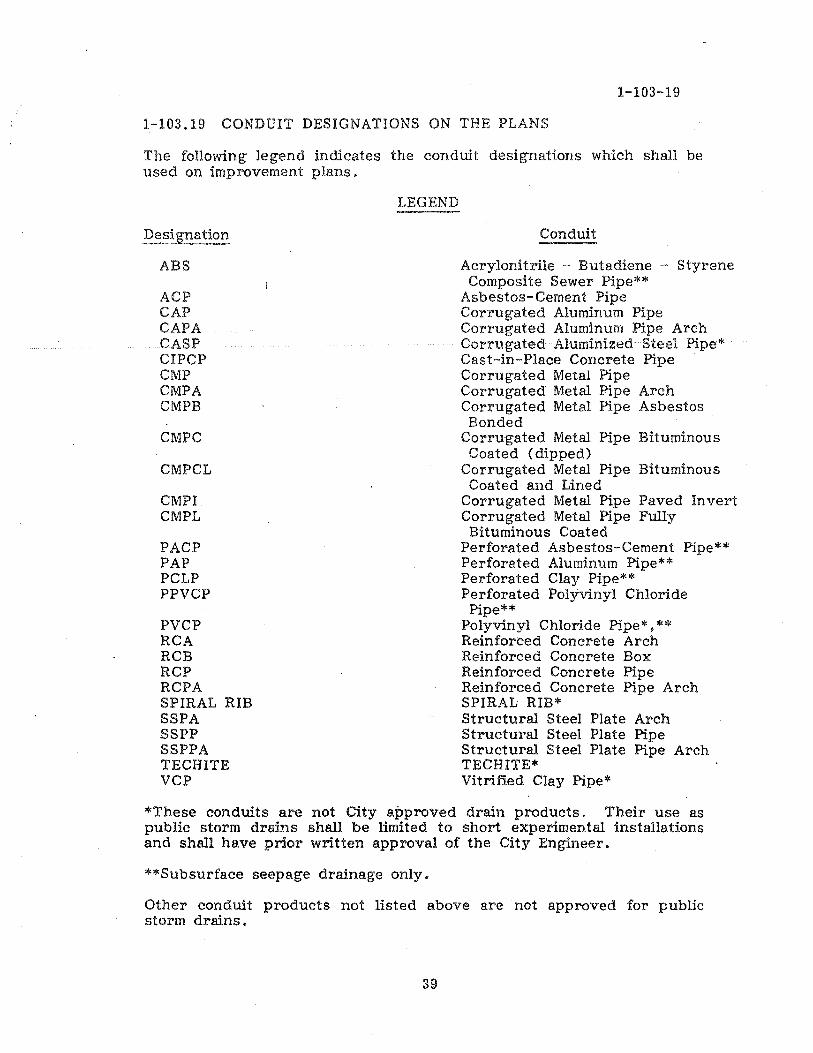
1-103.19 CONDUIT DESIGNATIONS ON THE PLANS
The following legend indicates the conduit designations which shall be used on improvement plans.
Designation
ABS
ACP CAP CAPA CASP CIPCP CMP CMPA CMPB
CMPC
CMPCL
CMPI CMPL
PACP PAP PCLP PPVCP
PVCP RCA RCB RCP RCPA SPIRAL RIB SSPA SSPP SSPPA TECHITE VCP
LEGEND
Conduit
Acrylonitrile - Butadiene - Styrene Composite Sewer Pipe"'*
Asbestos-Cement Pipe Corrugated Aluminum Pipe Corrugated Aluminum Pipe Arch Corrugated Aluminized Steel Pipe*' Cast-in-Place Concrete Pipe Corrugated Metal Pipe Corrugated Metal Pipe Arch Corrugated Metal Pipe Asbestos Bonded
Corrugated Metal Pipe Bituminous Coated (dipped)
Corrugated Metal Pipe Bituminous Coated and Lined
Corrugated Metal Pipe Paved Invert Corrugated Metal Pipe Fully Bituminous Coated
Perforated Asbestos-Cement Pipe** Perforated Aluminum Pipe** Perforated Clay Pipe** Perforated Polyvinyl Chloride
Pipe** Polyvinyl Chloride Pipe*. ** Reinforced Concrete Arch Reinforced Concrete Box Reinforced Concrete Pipe Reinforced Concrete Pipe Arch SPIRAL RIB* Structural Steel Plate Arch Structural Steel Plate Pipe Structural Steel Plate Pipe Arch TECHITE* Vitrified Clay Pipe*
"'These conduits are not City approved drain products. Their use as public storm drains shall be limited to short experimental installations and shall have prior written approval of the City Engineer.
**Subsurface seepage drainage only.
Other conduit products not listed above are not approved for public storm drains.
39

1-103.20
1~103.20 EASEMENTS
A. Minimum Widths
The following table is a general guide for establishing minimum easement widths. although special conditions, such as deep locations. may require additional widths.
Pipe Pia. or Equiv81ent
(inches)
18-35 36-60 61-84 85-108 Over 108
10 15 20 25 30
B. Storm drains and easements are to be placed on one side of lot ownership lines in new development and in existing developments where conditions will permit.
C. Generally storm drain easements are to be established exclusively for drainage facilities. Joint use easements will be permitted, such as sewer, water, etc. where necessary, except each line shall be separated by a minimum of five feet (5') horizontally.
D. Access Easements. Physical access shall be provided to all storm drain easements. Should special access to storm drain easement be required because of grade differential, a mImmum access easement of fifteen feet (15') shall be established. A minimum access road shall be provided in the access easement, twelve feet (12') wide. with a maximum grade of fifteen percent (15%). Maintenance vehicle access to the channel is required every 1500 feet or more often as needed.
E. In areas to be improved over a storm drain easement, only at-grade parking lots or fences may be constructed. This construction must be approved by the city. and the owner must execute an Encroachment Maintenance and Removal Agreement to the City. In general, structures are not permitted over or within storm drain easements.
F. Storm drain easements for pipes with fifteen feet (15') to twenty-five feet (25 ' ) of cover shall require an increased easement width based on two (2) additional feet of easement for every foot of cover over fifteen feet (15').
40

Example: 18" pipe with 20' of cover Minimum easement width Additional easement 2 x 5
TOTAL EASEMENT WIDTH
:::::
:::::
10' 10'
20'
1-103.20
G. Special easement widths will be determined based on a specific project basis for all storm drains with cover in excess of twenty-five feet (25').
H. All pipes twenty-four inches (24 T!) in diameter and larger, enlarge easement on one side at structures (inlets. cleanouts. etc.) to twenty feet (20') for maintenance access.
I. For all pipes forty-eight inches (4'8") in diameter and larger:
(1) Provide a twelve foot (12') graded access road (fifteen percent (15%) maximum) to upstream inlet;
(2) Easements to downstream outlets must be twenty feet (20') minimum width for maintenance access.
1-103.21 DESIGN TABLES AND CRITERIA
A. TABLE 1-103.21A Design Values for Manning Roughness Coefficient (n)
B. TABLE 1-103.21B D-load Requirements for Reinforced Concrete Pipe
*C. TABLE 1-103.21C Maximum Height of Cover for Corrugated Steel Pipe - 2-2/3!f x 1/2!! Corrugations
*D. TABLE 1-103.21D Maximum Height of Cover for Corrugated Steel Pipe - 3" x 1 ff Corrugations
"'E. TABLE 1-103.21E Maximum Height of Cover for Structural Steel Plate Circular Pipe - 6" x 21t Corrugations
*F. TABLE 1-103.21F Maximum Height of Cover for Steel Pipe Arches-2-2/3" x 112ft Corrugations
*G. TABLE 1-103.21G Maximum height of Cover for Structural Steel Plate Pipe Arches -6" x 2" Corrugations
*H. TABLE 1-103.21H Maximum Height of Cover for Corrub'ated Aluminum Pipe 2-2/3" x 1/2" Corrugations
41

1-103.20
*1. TABLE 1-103. 21I Maximum Height of Cover for Aluminum Pipe Arches - 2-2/3" x 1/2" Corrugations
J. TABLE 1-103.21J Suggested Depth and Spacing of Underdrains for Various Soil Types
>I< Refer to the Special Requirements Under Section 1-103.14 O.
TABLE 1-103.21A
DESIGN VALUES FOR MANNINGS ROUGHNESS COEFFICIENT (n)
TYPE OF CONDUIT
"'Metal Pipe and Pipe Arches (2-2/3" x 1/2" Corrugations)
NOTE: NO reduction in n Value is permitted lor Lining of metal pipes.
"'Metal Pipe (3" x 1" Corrugations)
*Metal Pipe and Pipe Arches (6" x 2" Corrugations)
Reinforced Concrete Pipe
Concrete Boxes and Arches
Cast-In-Place Concrete Pipe
Clay Sewer Pipe
Asbestos - Cement Pipe
CAP Helical
*CMP and CAP ANNULAR
42
n Value
0.024
0.000
0.027
0.032
0.013
0.015
0.015
0.013
0.013
0.022

REV.
TABLE 1-103.218
[)..Ioad requirements: ordinary bedding, dead load factor 1.50
Cover in feet
Pipe diameter In Inches-D-Ioad in pounds per foot 1e :<1 24 27 30 :l3 36 39 42 JS 4S 51 54
2.0
4.0
15.0
11.0
7.0
11.0
',1P4 lela? 1030 993 961 1137 918 1103 1037 1025 10n 995 985 972 964
10.0 1250 114' 1090 1047 1015 992 973 9?9 nos 1096 1M2 1065 1055 1042 103J
11.0 1301 119~ 1141 1098 1067 1043 1026 1012 "77 1165 1151 113J 1123 1110 1103
12.0 13J7 1236 11117 1145 1115 1092 1075 1062 1242 1231 1217 1200 1190 1177 1170
14.0' 1426 1315 1269 1229 1201 1181 1166 1155 1365 1356 1343 1326 1317 1304 1297
16.0 1490 1380 1~ 1301 1276 1259 1247 1239 1477 1470 1458 1442 1434 1422 1417
18.0 1541 1433 1396 13&3 1341 1327 131e 1312 1578 1574 1564 1549 '543 1532 1528
20.0 1582 1477 1445 1415 1397 1366 1380 1378 1670 1669 1661 1547 1643 1833 '631
24.0 1542 1542 1519 '''96 1485 1482 1483 1486 1828 1833 1830 1819 1820 1813 1816
211.0 1679 1585 1570 1554 1550 1653 1560 1571 1955 1967 1969 1963 1969 1966 1973
1703 1613 1roS 1595 1597 11lO6 1619 1635 2058 2077 2085 208.:l 2094 2095 2107
316.0 1716 1632 1629 1624 1631 1&40 1664 1686 2141 2166 2180 2163 2198 2204 2220
40.0 1727 1544 1545 1544 1658 1675 1698 1724 2208 2240 2258 2:26S 2286 2296 2317
Design criteria
~I-D-load values giver, in the table indicate greater accuracy Iha,., warranted In field installation. thus. when specifying. pipe should be classified ''1 5O-D increments; tor example. 8OO-D. 850-D.
Bedding-The above table is based on installations Wlth ordinary bedding' and should not be used for other conditions. except as noted. D-loads given in the lable are based on a load factor of 1.50. For classes 01 bedding witl1load factors other than 1.50. the corrected dead load may be obtained by muhlplyll''Ig the table's dead load by 1.50 and dividing by the desired dead load factor
B3ckfllF-Based on Marston's curve for saturated lopsoil. when KJ.(=0.150. the table is conservative for sands, gravels and cohesion less materials. The D·load should be recomputed for clay backfills, when K,. > 0150, using the correct coefficient The table has been computed using materials with a unit weight of 110 pounds per cubiC foot For materials having a unit weight other than 110 pounds per cubic foot. the correct dead lcad can be calculated by multiplytng the dead load shown in the table by the desired unn weight and dividing by 110.
~h \fridth-O-Ioads given in the table are based Ofl trench widths (at top 01 pipe) 01 pipe OD plus 16 inches for pipe diameters 33 IOChes Of less;
and pipe OD pius 24 Inches lor pipe diameters greater tnan 33 Inches PipeODs are basec on wall thicknesses given In the dimenSIonai data table 10' Wall A pipe throwgr, 96-inChdlarne:er. and on wall thicknesses giver. In laDle for large diameter pipe Wllh 102· ana lOS-Inch diameters Thicker wall designs may require a sllgh.tly higher D-lcad classification.
For earth covers of two to eight feet the tabulated dead lcad D-loads approach the maximum loads 1ha' occur at the transiltOn trench wiott' .. The difference to dead load for wide' trench widths or the projecting conduit conditions may be a small value and the pipe may safely withstand the Iflcrease. For assurance it will be
CITY OF SAN DIEGO DESIGN GUIDE SHT. NO.
D-LOAD REINFORCED
REQUIREMENTS CONCRETE PIPE
43
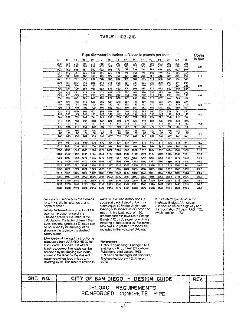
TA8LE 1-103.218
Pipe dla~ In inchH-D-1oad in pounds per foot Cover
957 951 945 940 Iol36
1027 1021 1016 lOll 1006
1096 1090 1085 1080 1076 1163 1157 1152 1148 1144
1292 1287 1283 1279 1275
1412 1409 1405 1403 1400
1525 1523 1521 1519 1518
1630 11129 1629 1629 1629
1818 1821 1825 1828 1632
le80 11187 1994 2002 2009 2118 2130 2142 2153 2164
2237 2253 2289 2285 2300 2338 2359 2379 2399 24;8
necessary to recompute the D-Ioads f()( any installation change at any depth of cover.
s.tety tac:t0l'-A safety factor of 1.0 aga,'ls\ the occurrence of the O.Ol-inch crack is assumed in the calculatJOns. If a factor diHerent than 1.0 is oesired. corrected D-loads can be obtained by multiplying loads shown In the table by the desired safety factor.
l.M!! ~ive load distribution is calculated from AASHTO HS-20 for tnx;k loads'. For diHerent wheel loadings. correct live loads can be obtained by multiplying live loads shown in the table by the deSired maJtimJm wheel load in kips and dividing by 16. ThiS table is limited to
S32 828 824 til21 818 1115 813
1002 996 895 l1li2 1111!19 1186 984
1072 106!! 1065 lOB2 1059 '. 1OS7 1054
1140 1137 ',34 1131 11.28 1128 1124
1272 1270 1267 1265 1263 12'62 1260
1396 1397 1395 1394 1393 1392 1391
1517 1517 1511\ 1516 15111 151& 1516
1630 1631 1631 1632 1633 1634 1635
1635 1839 1842 1&48 1850 1853 1857
2016 2032 2030 z:m 2043 .205Cl 2056
2175 211*1 2100 2206 2216 2226 2235
2315 2329 2343 2357 2371 2383 Zl:96
2437 2456 2474 24111 250a 2524 2540
AASHTO live load distributions (a square at backfill depth, H. whose sides equal 1. 75H) for single truck loading with impact factors based on depth. A live load 1 actor 01 1.50. recommended in Iowa State College Bulletin 112 by Spangler lor ordinary beclding or better. is used For covers nine feet and greater. rove loads are included in the indicated D-Ioads.
~nea 1. 'Soil Engineering: Spangler. M. G. and Handy. R. L; InteXi Educational Publishers, third edition. 1973. 2. 'Loads on Underground Conduits: Engineering Ubrary '·2. AmerOfl. 1973.
in feet
2.0
2.5
3.0
4.0
5.0
11.0
7.0
11.0
Ill' 00II 81B 1114 11.0
962 1179 l1li1 1187 10.0 1052 1050 1063 1059 ".0
',22 "2Q 1135 "31 12.0
1258 1251 1275 1272 14.0
1390
,_ 1411 1409 111.0
151S 1516 1542 1542 18.0
1636 1637 1668 1669 20.0
11160 1863 1903 100II 24.0
2062 2068 2118 2126 28.0
2244 2253 2313 2326 32.0
2408 242Q 2490 2509 36.0
2556 2571 2651 2675 40.0
3. 'Standard Specification for Highway Bridges: American Association of State Highway and Transportation Officials (AASHTO), twelfth edition, 1973.
SHT. NO. CITY OF SAN DIEGO DESIGN GUIDE
D-LOAD REINFORCED
REQUIREMENTS CONCRE TE PIPE
44

,g:.. Vl
s: » ~ ~ C s:
NO 10 ~< ~::m
x:::O ..... -N:"'!1
0 o.:u 0 0 ;00 ;0:::0 C;o G'lC l>G'l -t» O-t zm <nO
(f) -f f11 f11 r -0
~
::0 rrI :<.:
0 -t -< 0 '"r1 U) » Z 0 f11 Gl 0
• 0 r'1 en -C) z Gl C 0 m
til
~ Z 0
MAXIMUM H£IOHT OF COVER FOR CO"RUOAr~D STEtL rIPE
2-2/)" x 1/2" CorruGations
~:UifllUIII HOight- of Covel" (r&I:tt.)
5/16" Rheta )/0" lihet~ Dhllleter
lnchclJ 18 rfjG 1!- p-oflc 1" £'1'1"16 12 cafie 10 nefje 8 £1$5-.0 Z' .Ol?' • 10q' .. 1)0' .. 16 .. .064
s nwu: IHV..,,..I:.1>
12 6) 6) 8) 15 ~~ ~~ 66 ~ 16 fa5 84 21 )6 36 .1 12 1)04
Z'J )2 JZ "Z 61 1S I .... ,30 2$ ~~ 49 60 74- 0
I.> )6 21 41 50 62 .
N .... DOUnL£ RIVETED
n
I "2 ,.0 ~l 12 76 80 ,.6 35 6) 61 70 51&. JI~ 56 59 6) 60
~~ 53 56 66 49 ~~ 12 45 ~g 43 I, ''-40 40
Noh: Scaflls lIVIa:r be r!veted~ "clded 01' helle.l lock 8101!lf'll.
CalifornIa DlvlIJ10n or Hlgh~~1'
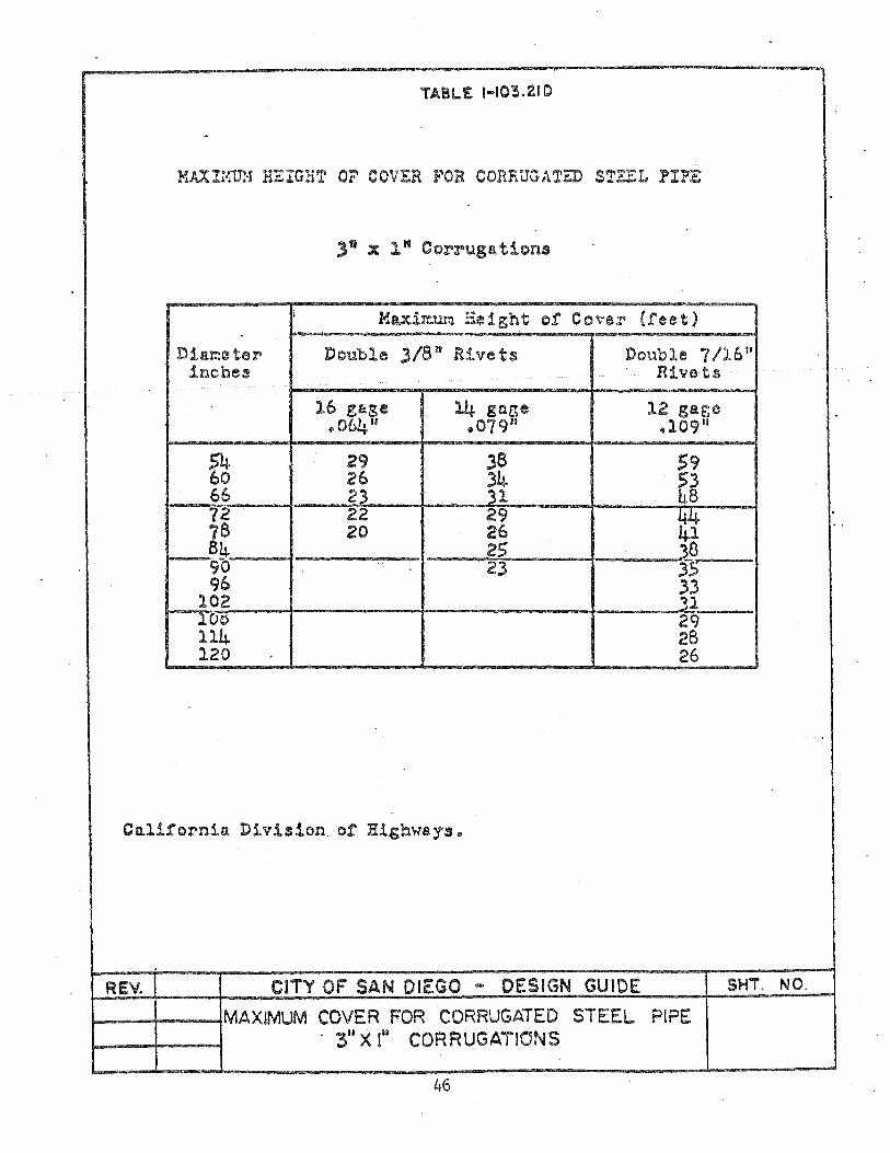
TABLE 1-10'3.2.10
MAXlrM·! H:.:rGHT OF COVER FOR CORRUGATED STEEL PIPE
3~ X 1" Corrugations
i loiuir.:.ur:1 Height of Co\"er (feet)
Diareeter Double 3/8" Rivets Double 7/16" inches Rive ts
16 gage 14 gaGe 12 gage .064 81 .079" .109"
S4 29 38 59 60 26 ~ 53 66 23 h8 72 22 29 t
. 78 20 26 84 25 )8 90 23 r5 96 ~i 102
lOc> 29 114 28 120 26
Calii'ornin Division of Rig:!:::n·tays ..
REV. CITY OF SAN DIEGO'" DESIGN GUIDE SHT. NO.
~--+--~MAXIMUM COVER FOR CORRUGATED STEEL PIPE . 311 X (.. CORRUGATIONS
46
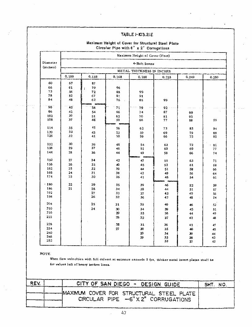
T4Bi...£ H03.2IE
Maximum H~ight of COV@f for Structural Steel Plat4'l Circular Pipe with 6" l( 2" Corrugations
Maximum Height of Cover (Feet)
Diameter 4-Bolt Seams (inches)
METAL THICKNESS IN INCHES
0.109 0.138 0.168 0.188 0.218 0.249 0.280
60 67 87 66 61 i 79 96 72 56 I 72 88 99 78 52 67 81 91 84 48 62 76 85 99
I--- -90 45 58 'H 79 92 96 42 54 66 74 87 99
102 39 51 I 62 70 81 93 108 37 48 59 66 77 88 99
I--- -114 35 45 56 62 73 83 94 i20 33 43 53 59 69 79 89 126 32 41 50 56 66 75 85
I 132 30 39 48 54 63 72 81 138 29 37 46 51 60 69 77 144 28 36 44 49 58 66 74
10--150 27 34 42 47 55 63 71 156 26 33 40 45 53 51 68 162 2S 32 39 44 I SI 58 66 168 24 31 38 42 49 56 64 174 23 30 36 41 48 S4 61
~-. 180 22 29 3S 39 46 52 S9 186 21 28 34 38 44 51 57 192 27 33 37 43
I 49 56
198 26 32 36 42 48 54
204 25 31 35 40 46 52 210 24 30 34 39 45 51 216 29 33 38 I 44 49 222 28 32 37 I 42 48
228 28 31 36 41 47 234 27 30 35 40 45 240 29 34 I 39 44 246 29 33 38 43 252 33 '51 42
NOTE
When now velocities with full culvert at entrance exceeds 5 (Pll, thicker metal invert plates shall be
Cor values left of beavy broken Hnes.
REV. CITY OF SAN DIEGO ... DESIGN GUIDE
1---+--~MAXIMUM COVER FOR STRUCTURAL STEEL PLATE CIRCULAR PIPE _s't X 211 CORRUGATIONS
47
SHT. NO.
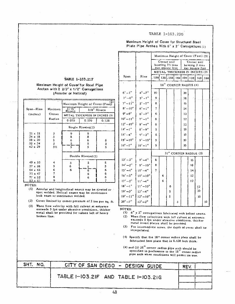
tA!U: 1-103.2lF
Maximum Height of Coverifor Steel Pipe Arches with 2 2/3" l( 1/2" COfrugations
(Annular or Helical)
Span-Rise
(inches)
21 x IS 24 x 18 28 x 20 35 x 24 42 x 29
49.x 33 57 x 38 64 x 43 71 x 47 77 x 52 83 x..5..7
NOTES:
(2) Maximum Height of Cover (Feet)
Minimum 5/16 3/8" Rivets Rivets Comer f-M!.:E:..!.T':::'A=-L~T-H.J..I-C-K-N-E-S-S-IN--IN-C-H-E-S-(-3"""i) Radius
0.079 0.109 0.138
Single Riveted(1)
3 9 9 3 8 8 3 6 6 6 3 __ L~ 5 5 3\t\ 5 5 5
Double Riveted (1)
4 5 5 5 5 6
t--L -5
6 6 6 6 7 6 6 8 6 6 9 7
(1) Annular and longitudinal seams may be riveted or spot welded. Helical seamS may be continuous lock seam or continuous welded.
(2) Cover limited by comer pressure of 2 ton per sq. ft.
(3) When flow velocity with full culvert at entrance exceeds 5 Cps under abrasive conditions, thicker metal shall be provided for values left of heavy broken line.
TABLE 1-103.21G
Mall imum He ight of Cover for Structural Stet'! I Plate Pipe Arches With 6" )( 2" Corrugations (1)
Maximum Height of Cover (Feet) (3)
Corn"r soil Comer soil bearing I'll Ions bearing 3 Ions ~per squat" foot . per SQuare foot METAL THICKNESS r.-; INCHES (2)
Span Rise .109 138 .168 .188 109 138 .168 188
18 11 CORNER RADIUS (4)
6' -I" 4'-7" 10 \20 7'-0" 5' -1" 9 18
7' -1 i" Sl _., -I 8 16
8'_10" 6'-1" 7 14
9' -9" 6'-7" 6 12
10'-11" 7'-1" 6 12
12' -10" 8'-4/1 6 12
14' -1/1 8'-9" 5 10
15' -4" 9'-3" 5 10
15'-10" 9'-10" 5 10
16'-7/1 10'-1" ·5 10
31/1 CORN'ER RADIUS (5)
13'-3" g'-4" 8 16
14' -2" g'-IO" 8 16
15' -4/1 10'-4" 7 14
16'-3/1 10' -10" 6 12
17'-2/1 11'-4/1 6 12
18'-1/1 II' -10/1 6 12
19'-3" 12'--4/1 5 10
19'-11" 12'-10/1 5 !O
20'-7" 13'-2/1 5 10
NOTES: (1) 6".x 2~' corrugations fabricated with bolted seams. (2) When flow velocities with full culvert at entrance
exceeds 5 Cps under abrasive conditio·ns. thicker meta! invert plates shall be provided.
(3) For int~rmedi"te si".,s, the depth of cover shall be interpolated.
(4) Specify that the 18" comer radius plate shall be fabricated from plate that is 0.138 inch thick.
(4) and (5) 31" corner radius pipe arch should be specified in preference to the 18 II comer radius pipe arch when conditions will permit its use.
SHT. NO. CITY OF SAN DIEGO - DESIGN GUIDE REV.
TABLE l-I03.2JF AND TABLE ' .... I03.2IG
48

T.UU 1-103.2111 TABLE 1-103.211
Maximum Height of Covllr fOf COmlgatecl Aluminum Pipe Maximum Height of Cover for Aluminum Pipe Arches
with :2 2/3" x 1/2" Annular & Helical Corrugatioos with 2 213 ff :II( 1I2ff Annular and Helical Corrugations
Maximum Height of Cover (Feet) Maximum Heiv;ht of Cover (Feet) (2)
Span Minimum
Diameter METAL THICKINESS IN INCHES (2) & Com.er METAL THICKNESS IN INCHES (3)
(Inches) 5/16 fI Rivets 3/8 1f Rivets Rise Radius 5/16 ff Rivets 318
ft Rivets
(Inches) (Inches)
.060 .075 .105 0.135 0.164 0.060 0.075 0.105 0.135 0.164
Single Riveted (1) Single Riveted (1)
17 x 13 3 8 12 91 99 21 x 16 3 8 15 73 91 99 24 x 18 3 8 18 60 76 99 28x20 3 6 21 52 65 91 3S x 24 3 S 24 45 57 79 99 42 x 29 3 1/2 5 30 45 63 82
36 38 53 68 Double Ri veted (1)
Double Riveted (1) 49 x 33 4 5 57 x 38 5 S
42 45 58 64 x 43 6 6 <IS 39 51 62 71 x 47 7 6 54 41 51 77 x 52 7 5 60 33 42
83 x 57 7 6 66 34
72 26 NOTES:
NOTES: (1) Seams may be annular riveted or helical lock seam only.
(1) Seams may be annular riveted or helical lock seam (2) Cover is limited by comer soil bearing pressure of only.
2 tons per square foot.
REV. CITY OF SAN DIEGO - DESIGN GUIDE SHT. NO.
TABLE 1-I03.21H AND TABLE·1-I03.2!I
49

\Jj o
0 f11 '1J -f
-n I 0 :::0»
Z ~O ~(J) O-u Cp u)o (J)Z OGl
ro -n
-f -(C -u Z f110 U')f11
:u 0 ;U l> Z (J)
en ::J: ~
Z P
0 =t -(
0 '1l
en » Z 0 -PI C> 0
• 0 PI U) -C) Z
Q c --0 f11
:lB
~
Suggested Depth and Spacing of Underdrains for Various Soli Types
Soil Classes Soil Composition Drain Spacing (Feel)
Percent Percent Percent 3 Ft. Deep " Ft. Deep 5 Ft. Deep 6 Ft. Deep Sand Silt Clay
Clean Sand ............. 80-100 0-20 0-20 110-150 lS0-20U Sandy Loam ............ 50-80 0-50 0-20 50-100 100-150 Loam ......... ·.··.·· . 30-50 30-50 0-20 30-60 40-80 50-100 60-120 Clay Loam· ............ 20-50 20-50 20-30 20-40 25-50 30-60 40-80 Sandy Clay ............. 50-70 0-20 30-50 15-30 20-40 25-50 30-60 Silly Clay ............. 0-20 50-70 30-50 10-25 15-30 20-40 25-50 Clay ............... , .. 0-50 0-50 30-100 IS (max.) 20 (max.) 25 (max.) 40(max.)
NOTE: Depth Is measured 10 invert of pipe. ~ m r A -• 0 (p.I
N c:..
California Division of JUghways"
1-103.22
1-103.22 DESIGN GUIDES
A. FIGURE 1-103. 22A
B. FIGURE 1-103.22B
C. FIGURE 1-103.22C
D. FIGURE 1-i03.22D
E. FIGURE 1-103.22E
F. FIGURE 1-103.22F
Typical Plan in Improved Street (Flat Grades)
Typical Profile in Improved Streets (Flat Grades)
Typical Plan in Easement (Steep Grades)
Typical Profile in Easement (Steep Grades)
Typical Plan - Combination of Flat and Steep Grades with Curved Alignment and Profile.
Typical Profile - Combination of Flat and Steep Grades with Curved Alignment and Profile.
G. FIGURE 1-103.22G Typical Plan in Easement with Complex Alignment on Fill Slope.
H. FIGURE 1-103.22H Typical Profile in Easement with Complex Alignment on Fill Slope.
51
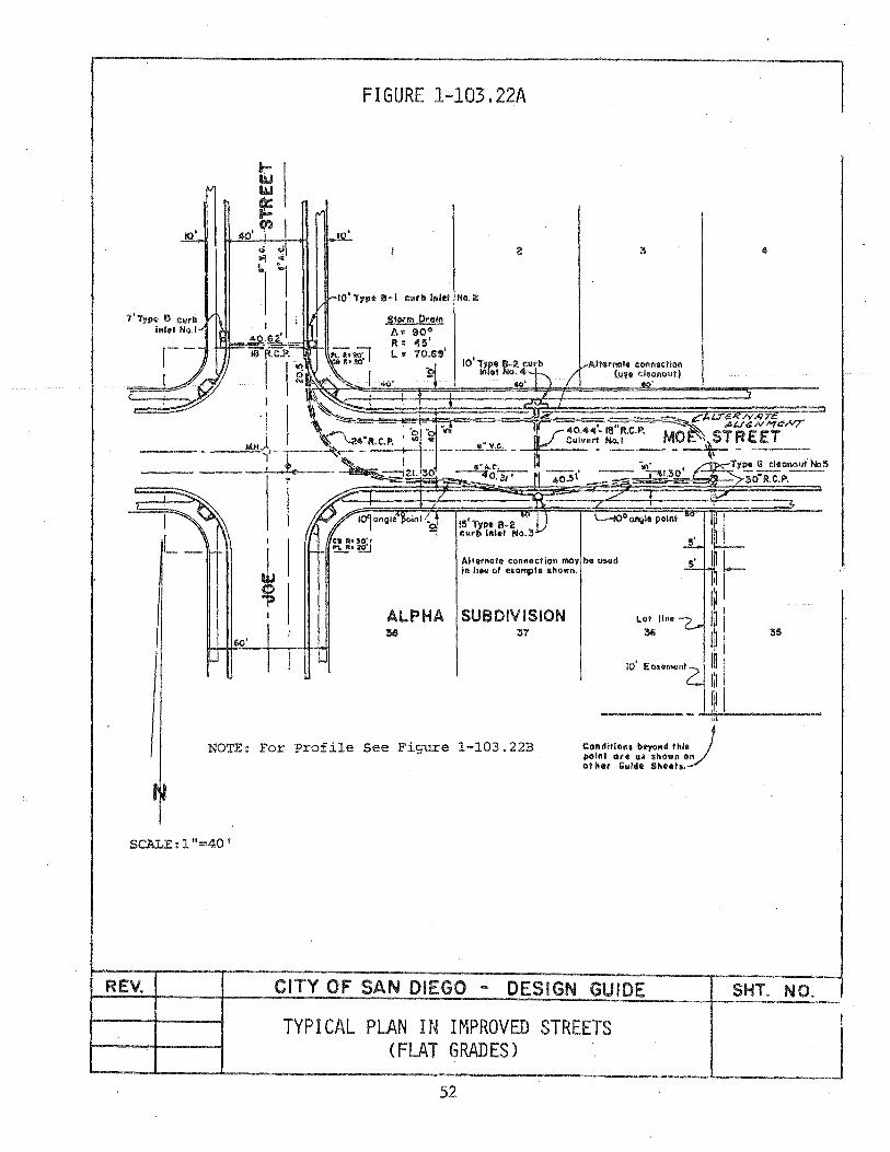
1'Type 6 curb inlel No.1
I 1_-
I I I
~I
FIGURE 1-103,22A
Allernot. connection l'I\Oy be used in Ii ... of elQlf(l)le ahown.
o Ctn9141 polnl
ALPHA SUBDIVISION Lot line
:!l8 :37 ~
NOTE: For Profile See Figure 1-103.22B C::ol'ldrtlou b~Ad Ihl.J poll'lt are 01 ahown on
SCALE:l"=40'
REV.
Of II.f Gwlel. Shoela.
CITY OF SAN DIEGO - DESIGN GUIDE
TYPICAL PLAN IN IMPROVED STREETS (FLAT GRADES)
52
SHT. NO.
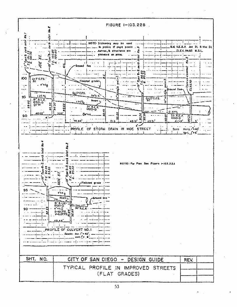
FIGURE 1-10:3.229
... ~ , ~ I I
- .~ . ~- --. -'-~ ..... ~;r : 1-;,::' ....... :-1 -=-- .. ---~---I-t: --L-..... .....-,~.,I'--.,.I-,..I-·F""'"·!i--":";--r-.. ... • •• _._ "" " ....... :........j. ....... ____ ., ............ 1111 ........ ., mOJ "G 11M.. •• -- - ..... ---r--. - ... --_.
:; '.. ' __ ~ __ ' __ I -t. .:.- ~-- 111\ prof till If IMql. p~u • .., ~_ •• __ • _L-.....-u H..f.Il.P. .toll 51. fa M08 51. ~..,C) ... - ~~ . --,~--!-- . ..QII'''u,~ SfflllClllfU Ill. • ~ .. ____ !: AtV. H..II3 au,L..
~'-' • ..... '.'.' 1 • , • : t t ,
lID,· . .....: .!'I g ti ' .... _;.........:..--l._~ -. !A&Gf>tIeell 011 ,1IMI1.. • ,--... ..---- ..J~--- _ .•. -. t .. t:)~ .... .. ... \:) . I ~. ; : : , :' , :.., --.:......: __ ~"'.~---¥"'-~ .",: -J. 'I .' I , . .l£ I ' , '::t±" 'Ii
• ..:~\:) "'" • ~fQ. • •• , •• ',,"r'" --I .... , .• "III .. 1, .... -.---, - 1-' lit· ... ~ n t':!'l1ilOoo '. I.' .
..... . ":i." " GroIlOd 11m •••• _J •• -:. '''!'--r "r'-'" i: 1----:-- -~~ .... ,-~., -- . I. I , "I 'I . ........ _ ,. --_.,---, , .. " -_.- .- ---IN... . .. -.- "--1"'--'" -.'. I
• • !' • -.~ • I' f ._ •• ,1-._. -~ .-.!.... •..• ! ..... lID\:).... .-.--or. ,--l_.L... .... -,- .. ~-.
, '_" .. 10"; ~ ---. C'" !!I.~" ... .. ---........ _--. 1· ..... -:-" ~t.>~ " ~--, .....:.-.;.........: ~ '" ./, ... -•• ..: ••• _ ~ L.: t --: .... ;., .. ..; •• - ; -~ •• ,~~. _._,
. . ... I . ; -t .. ••• ... _. • 11ft ii: ----
"-."~
,_ ... f._~_ .... _2._.i~ .. i_._!. ... .. '. .. ,. --,1-": ... : --.PROFILE OF ST,ORM DRAIN IN
~-----!.._ ~ fl· t • .......... [_1;.......;,. __ ... '_.;,.. __ . _____ ..... _"---'--..1 __ ....... __ _
;. ,I "-,' ··cr; ...... ' tIotf z. ,P, 40' ; .~"'..l·.·r: __ _
'II'
~ "" ... ~ ~ ....
--,--.-~ .... - .~ ------!-""I - - --- 4l -.--~ ... --.~ ~ ... - .... ! ... ...: I ,-
~ ! . 0.... : , . __ ._--... :-~-'-'~' --.- ----·-T=F __ ,,,_., •• Vd, _____ ... _ "- __ • _____ ._
, t "" . N ~() I
.----- II:) I:,t:) ---. 'i:I'II .-. : -t--.. .... c::3,,' t= -' ... ~~~- -'\..:'. tl;: ." I
',--- :- ~ '\jIG -. eo, !:5\i. - _. . , . ~---.. - ... t.. ,., i4J ' .... e.; '0 , .,-- -, -..,... -!- .,.--
-: .... -_ .. ,.\ ... -~ ..... , -- - '(F1flh~ "GIlt ;'--
-~5 ............... - ../ ....... _~I· -'-j---.. .. ,. I! .'_"' __ .......... A.t'.a _ .. ___ ._"'. __ ,_
-'- . __ .... ........,."1. fllyu~ "",IS 1111«-
-'._._- ... : - 18"F!."F.'-., . -- . . _-, ...... '. G~O-O' -r.:::..-- '.' i' 90' . ,~ • •• .. ,e.O .J ~ ~'It.C:'''., - ,-. . ---.... +:i O"IOC"'S. ~:"'! .. , . -.: . ...; .. '1-" .'-_. --l...-.!.-, .: . V'6.0F.~r .-"':"-~--t--- - ":" -~ ... J.. ; 40 . .£4' j:. _...J --' -H-_ -7 : r".: ; I , . ...:=-; .. ; : :=
___ , __ ,.PROF'ILE OF ,CULVERT NO.1. " j ... ___ .-i--~.:- . ;, ... : •. SUle: !lot. 1".40' .
. ~.~._: " ."ft.!.":. ,'_'_.:.._~ __ , : ; .. ;.. --- .... _._.,. ._ ....... ..... .
SHT. NO. CITY OF SAN D!EGO DESIGN GUIDE
TYPICAL PROFILE (FLAT
IN IMPROVED STREETS GRADES)
53
REv.

REV.
FIGURE 1-103.22C
CITY OF SAN DIEGO - DESIGN GUIDE
TYPICAL PLAN {STEEP
54.
IN EASEMENT GRADES)
SHT. NO.
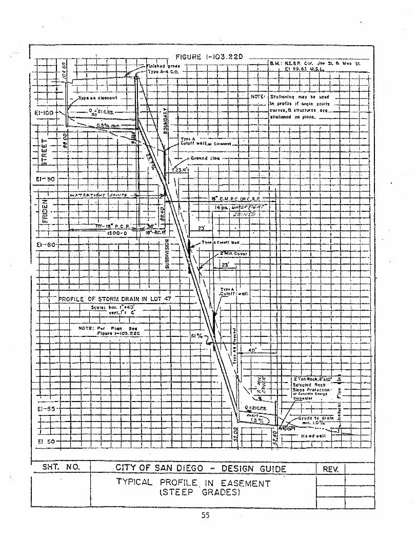
I
r---i- ~hOFIU:' OF STOR~.~ DRAIN IN lOT C Seale: liar. ,"a40'
-I-4-4-+--,f--+ 1:'::'="1 VIlr1. ('Z (,'
1 II J NOT!!:: Fof' ""41n S ..
1"'1911f. l-t03.%:ZC
1-IO~.22D
.. all
SHT. NO. .·CITY OF SAN DIEGO "" DESIGN GUIDE
TYPICAL PROFILE tSTEEP
IN EASEMENT GRADES)
55
REV.

REV.
FIGURE 1-103.22E
ntl~~t~~~~~~L~o~t~LI~~~~~~~~~~i-j
For profile s •• P/~v~e /-IPS.U;::
CITY OF SAN DIEGO - DESIGN GUIDE
TYP! CAL PLAN COf.1BINATION OF FLAT AND STEEP GRADES
WITH CURVED ALI GNr1ENT AND PROFI LE 56
el>lJ .. "II
~/c>,,:::: 17 cis. V=¢
SHT. NO.
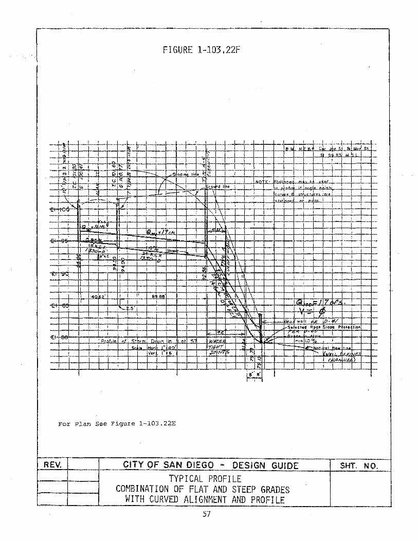
FIGURE 1-103.22F
, , , I , .~. I It I' I", '" R C'r ~. <: A 1 IAn, <;1
;; ~ IS' ! 9 ' R~ ... b ? .I~
'" ~~ I '" m .G odi
,~ U .... ~ ~" ' .If\' h" 1<:;,",' ,."' "' h h u\'d , 1-:1.:>
... I.:>p ~ I d I ~~ , .4, . i .A ,.,.1 ,
....
~ I-- - ",,,, .. <fL, .. ! n,. ,
\ -r- ,'n' '" ",' " I". l, I 1\ I .... , ....
I I"" \ I ! I I . I \ I
iJ'!!! h I~.k. \" .;.;£. (;j r:! 'r:k, ~ I
~, "E rI .... .\ -= -..,'" , IF!' , - ;:\\
! I ~ \-;'" In •• 1- !\ ~'\ 8 V. f'I '- n ~.:.:. -;v.
\ ~" 1\ c::. V \ f. ~ \' I
0\ '-: ~ I \ 1,..\ IS \ 1:.1 "" (>, '~ ~~ IV In ,
~ It"\: ~\ \ ~ ~ '\\\
'40'162' I! 8 es' , , .. !/.\ 1\ \ I Ii I I o '!.\ \, ltd Ie>/ 17 ~,
-,;;;- ,'" I I ~~.5 r .... <'t). [\ \ -I:'~ K\ ' - ., I 'I. Q "0 I IR lO- /
I':' s. eel. d R pck liloc " P
ole lion
I 14, \. -~
b' .... Pr, ~fll~ -;;'f C:. i,rm O,'"n ,n n' 0:;' !UI. ir.c.&< '01' r-.... ~ mon 1.0' ro
<;r, ~,. 101M, ," '40' -niP III , - ~'nw '''no
V., . I 6' ~ 1N7 ~ '~
" V.,,, ,,,r, ,,"'~ " .... c ',4'" !.vEl .)
~
#
For Plan See Figure 1-103.22E
REV. CITY OF SAN DIEGO - DESIGN GUIDE SHT. NO.
TYPICAL PROFILE COMBINATION OF FLAT AND STEEP GRADES
WITH CURVED ALIGNMENT AND PROFILE 57

10' I
, I .",ro· Il c.; •• ':10' Il- ~
: !I ! i
I!
REV. CiTY OF SAN DIEGO - DESIGN GUIDE SHT. NO. ~~~--~--~~~~~=T~Y~PI~C~A~L~P-L~A~N~--~~~---+--
IN EASEMENT 'WITH COMPLEX ALIGNMENT ON FI LL SLOPE
58
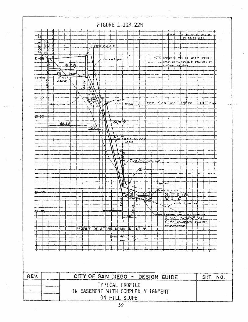
.' u
Ifl ~ ~ 10 . ~ 0 ;:: E? ! '-' e ;'
~ ~
':f
rv (
,.,
, .;
~" ,
,p
REV.
FIGURE 1-103.22H , I " t"l 1.. bJ. uL I 1 EI' 99~83 '>.I d , ,
1 1 , r rY} ~.IJ I"" .0 ! 1 I 1
11 1 I 1 1
'1 I Nr1TF 1"'0' nir. ",bv ts~d " 'of,l. of , I I 'ftRO' ~ nt' 1o, t • ,,. .. ,,. '" t.
'\ I~ .A, I Slali ned 1 on ' 010.
I
'Vn ""- 'n ..... 1\ ..
/ 1~:1n
,c&, I., -,
1\ \ , .\ \
'\ .... \\ \ (;)i i-I'S \
[\ I '- 1\ I A
~ I
I I V
I I I l
Fc r PIc n See FJq1 re 1~l.03 .1224 ; I i I I I I 1 I I 1 I
"\ ~I\ \ 1 1 I I j I I , I , I I ! I 1 I 1 , ,
f\ G'::'~ ,
I I 1 ! I , I .. .Y \\ 1\ I 1 I , 1 i - ,
1 \1 1\ 1 I 1 j i 1 1 \\ \ 1 T 1 I ., 1 I 1
I I I' \' ,Ai '0" 1.. .. : I i i , ! 1 \ 14. a':" I 1 , I ;
1\ I i , I 1 _0:. 1 I 1
1\ 1\ ~ 0 I 1 ! 1 1 1 !
\ \- I 1 1 i I , ,,,, ... 7y, l!!' -4- I rt ... 'A". 'ff 1 1 \ \ P ! 1
, ,
1 ,7 I 1
l\ ~ j \\ ., I' Je"" wol
\ ~\ ....... 1 .... pra . , drcli n !
~ % 2 1/ 18 e:::'; !i (!.p, • ,
10 ''''(" ~e_~ --Jt \., ':'1 cI , nt:
>e<.;; ~ I ... In.. I
10 ;<i [\ r--. ~ '\ ......... 1 , .'( I\. I".,. ·t., "., ., ,,,.. I ,i",;,
2. if) It '?IF IRA IP I"", f) 141 t:' ..
n. t .. .. ... ~RaFI !E bF s T5R DRA~ IN . 01 .~
col :Ii '.1 : 4. •
\Ie t. I : .
CITY OF SAN DIEGO - DESIGN GUIDE
TYPICAL PROFILE IN EASEMENT WITH COMPLEX ALIGNMENT
O~l FILL SLOPE 59
cR. T£. ENe ~""v' UP
i 1
i 1
, I
SHT. NO.

OPEN CHANNELS (1-104)
1-104.1 INTRODUCTION
1-104
A. An open channel is any waterway in which water flows with a free surface. The term shall be applied to streams. canals, channels. ditches. improved streets. and other conduits with no overhead restriction. It shall also include any conduit flowing partially full.
B. The design of open channels consists of computing a channel section which will carry the design discharge under the controlling conditions. adding two (2') minimum freeboard for projects under the Federal Emergency Management Administration Regulations. All other channels require one foot (1 f )of .freeboard above the energy gradeline for all other channels and 0.5 feet of freeboard above the energy gradeline for all brow ditches. Appropriate control shall be provided.
1-104.2 MINIMUM CHANNEL GRADIENT
Generally. the minimum gradient shall be 0.5 percent, provided this gradient is adequate to carry low flows. A flatter gradient may be approved where special provisions are made to provide for low flows.
1-104.3 CHANNEL ALIGNMENT
A. A bend in channel alignment should be located where the velocity is lowest and the change in direction should be as small as is practicable.
B. The minimum radius of curvature of the centerline of a channel shall be at least three times the width of a rectangular channel or three times the bottom width of a trapezodial channel to minimize development of spiral flow.
1-104.4 CHANNEL SUPERELEVATION
A. All horizontal curves shall be superelevated in drainage channels in accordance with Chart 1-104.4.
B. Superelevation of a channel shall be located as follows:
(1) In accordance with the formulae that follow. begin at a point 5 Lw downstream from the point of tangent of the curve with no allowance.
60

1-104.4
(2) Taper uniformly to full superelevation at a point 3 Lw downstream from the point of tangent on both blanks.
(3) Carry full superelevation to upstream end of curve on both banks.
(4) Continue top of bank elevation level from the upstream end of curve to its intersection with the normal top of bank.
(5) Super~levation Formulae
Lw =2T~ when F ~ 1
Lw =2T when F< 1
F=Froude Number :::: Q/A
Lw = Wave length -\jgA/T
T :::: Top width of water surface (feet)
C. Trapezodial channels with curved alignment under supercritical flow conditions will require special design considerations.
D. Transition Curves
Transition curves shall be used upstream and downstream from horizontal curves in rectangular channels for supercritical velocities where one of the following conditions exists:
(1) When the freeboard, above superelevated water surface (as calculated for the channel curve) i:;; less than one foot (1').
(2) In reverse curves or on alignments where curves follow one another closely.
(3) For any case where it appears desirable to eliminate cross wave distrubances.
The radius of the transition curve shall be twice the radius of the central curve.
The central angle of the transition curve shall be determined by the formula:
61
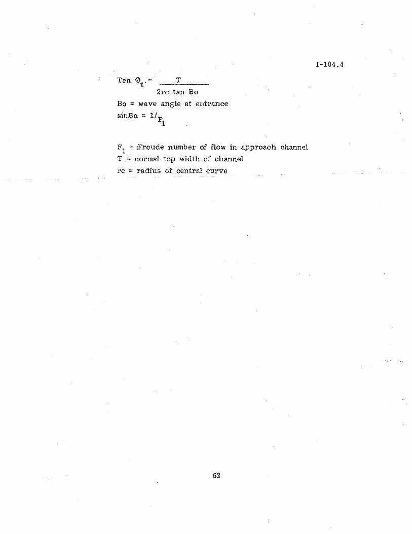
Tan eDt::: __ T ___ _
2rc tan Bo
Bo :::: wave angle at entrance
sinBo ::::: 11 F. 1
F 1 ::::: iFroude number of flow in approach channel
T ::: normal top width of channel
rc :::: radius of central curve
62
1-104.4
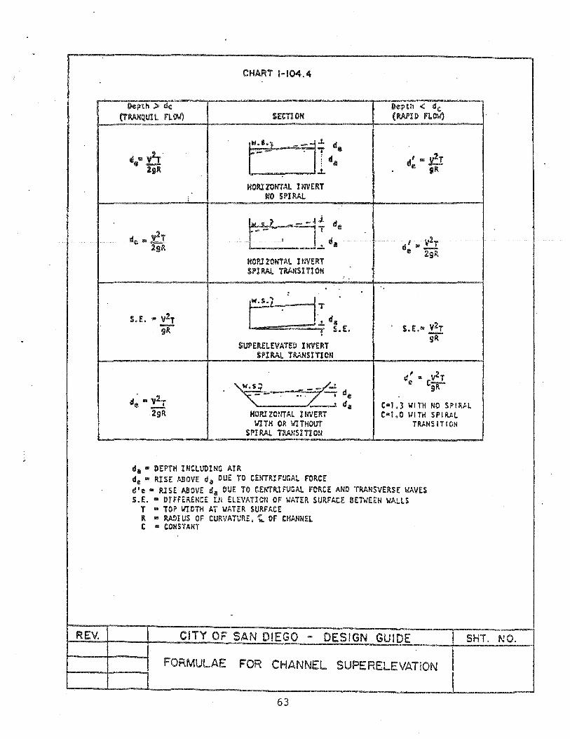
REV.
Depth:> «:1<;
(TAANQ.Ull nOlo')
CHART H04.4
HOPJ ZONTA!. ItNERT SPl~ TRANSITIOH
SUPERElEVATEO INVERT SPIRAL TRANSITION
d: II Cv2T SR
C-l.3 WITH NO SPIR#L C-l.0 WITH SPIRAL
TAANS I TI eN
cS ... DEPTH I NCltrol He AI R de • RISE ABOVE da DUE TO CENTRIFUGAL FORCE die'" fUSE ABOVE 41111 DUE TO CENTRIFUGAl F~RC:E AND TRANSVERSE WAilES S.£:. "" DIFfERENCE Ul ELEVATIOn OF WATER SURFACE BENEEN WALLS
T ... TOP WIDTH AT WATER SURFACE It .. MOruS OF CURVATUlU:. ~ OF CHANNEl. t ... CONSTANT
CITY OF SAN DIEGO - DESIGN GUIDE
FORMULAE FOR CHANNEL SUPERELEVATION
63
SHT. NO.

1-104.5
1-104.5 CHANNEL TRANSITIONS
A. Transiti.ons between tw.o different shaped channels shall be designed te pr.oduce a smooth, lew-head-l.oss transfer .of flew. The design shall c.onsider flew-rate changes. wall roughness. and channel shape and slepe.
The water surface level .of the d.ownstream channel must be set belew the i water surface level of the upstream channel by at least the sum of the increase in vel.ocity head. plus transiti.on and frictien losses.
B. Cenduit t.o channel .or channel t.o cenduit transitiens shall c.onferm te the cenditiens set f.orth in Item A. The channel dewnstream .of a conduit shall have a water surface far en.ough belew the cenduit te prevent a submerged .outlet fer a design sterm.
C. The maximum angle of deviati.on in any transitien shall be 12.5°.
1-104.6 ANGLE OF CONFLUENCE
A. Generally. the angle .of cenfluence shall be determined by the dewnstream flew characteristics. It shan be designed te produce a smooth. lew-head-l.oss transfer .of flew and shall censider flew-rate changes. roughness. and shape and slepe.
B. In ne case shall a cempenent .of lateral velecity eppese the mainline velecity by an angle .of c.onfluence.
C. A cenduit cennecti.on te a channel shall be made at an elevatien as near the t.op .of the channel water surface as pessible and the angle .of cenfluence shall be such as te preduce a smeeth l.ow-head-less transfer .of flew. '~
64
1-104.7 1-104.7 CUT-OFF WALLS
A. Lined channels shall have a cut-off wall constructed at each end of the lining along the full width of section.
B. Graded. unlined channels, or channels with rock slope protection shall have a rock or other type of suitable cut-off wall at each end along the full width or section.
1-104.8 DEBRIS AND SILT CONTROL FACILITIES
A. Where flows into a channel are likely' to carry floating debris and/or rocks in any quantity. a trash fence or rack, or deflector may be required up stream of the channel. This facility shall be designed and located to prevent an obstruction or blockage of the channel entrance. Maintenance access is required to all of these debris/rock collectors. The channel entrance and upstream area should be designed in such a way to provide for overtopping of the trash fence/rack without overtopping of' the channel or damage to adjacent property.
B. Should the flows be transporting significant quantities of silt. a temporary· or permanent silt basin may be required to prevent silting in the channel or downstream from the channel.
1-104.9 OUTLET DISSIPATOR
A. A suitable energy dissipator for all open channel flow is to be installed to reduce velocities to pre-improved conditions as follows:
(1) Where all channels discharge into an unimproved or na,tural channel and the velocities exceed those permissable for the material involved.
(2) At the end of street improvements where the street gutters discharge onto natural ground with velocities exceeding those permissable for the material involved.
1-104.10 CHANNEL TYPES
A. Unlined and Soft Bottom Channels
Such channels may be appropriate where the following conditions exist:
(1) A fully improved channel section is determined to be economically unfeasible.
65

1-104.10
(2) Adequate bank protection. where necessary, is to be installed for alignment control and for safeguarding adjacent property.
(3) Channel work will not significantly alter the watercourse or cause detrimental effects on adjacent property.
(4) Will conform to the permissible velocities as shown on TABLE i-104.10A.
;
(5) A low flow channel may be required should the main channel grade be determined to be so flat that drainage water will pond through the reach of the channel.
B. Grass-Lined Channels
(1) Grass-lined channels may be approved where the channel area is planned for open space use, is properly designed. and provisions are made to guarantee perpetual maintenance.
(2) Channel must conform to the permissible velocities as shown on TABLE 1-104.10B.
C. Paved Channels
(1) Trapezodial channels shall conform to the City of San Diego Standard Drawings.
(2) Other channel sections must be designed to withstand all loads to which they will be subjected. The following factors should be considered: hydrostatic uplift. lateral earth pressures. velocities and debris loads. truck surcharge. and possible wheel loads.
(3) Particular attention must be given to the sub drainage system which must be so chosen as to assure that upward pressure will be less than the weight of the lining.
D. Masonry Wall Drainage Structures
(1) The use of masonry walls for drainage structures is not permitted.
(2) The use of masonry walls for box culverts is not permitted.
66
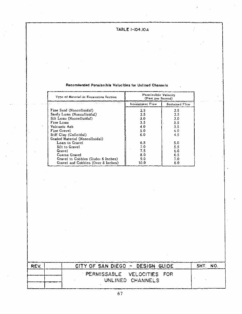
TABLE H04.10A
Recommended Permiuible V.locitiea for Unlined Channels
Type of Material in ExcllIvation Section Permissible Velocity
(F eet per Second)
Intermittent Flow Sustained Flow
Fine Sand (Noncolloidal) 2.5 2.5 Sandy Loam (Noncolloidal) 2.5 2.5 Silt Loam (Noncolloidal) 3.0 3.0 Fine Loam 3.5 3.5 Volcanic Ash 4.0 3.5 Fine Gravel 5.0 4.0 Stiff Clay (Colloidal) 6.0 4.5 Graded Material (Noncolloidal)
Loam to Gravel 6.5 5.0 Silt to Gravel 7.0 5.5 Gravel 7.5 6.0 Coarse Gravel 8.0 6.5 Gravel to Cobbles (Under 6 Inches) 9.0 7.0 Gravel and Cobbles (Over 8 Inches) 10.0 8.0
REV. CiTY OF SAN DIEGO - DESIGN GUIDE SHT. NO.
PERMISSABLE VELOCITIES FOR UNLINED CHANNELS
67

TABL.E 1-104.10 B
PE~~ISSIeLE VELOCITIES ~TH G~SS COVERS
Permissible velocity on Slope Erosion Eut Iy
Covel" ranQe res isul"lt soi 15 erded soils
Percent f.p.s. f.p.s. i ( 0-5 8 6
8ennud«lS!"us ( 5-10 7 5 (Over 10 6 4
suH'a lograss ) 0-5 7 .5 Kentucky blu~9r,ss ) 5-10 6 4 Smooth brome ) Over 10 .5 .'3 Blue gafl':l'n<1 )
"
Grau mixture ( 0-,5 5 4 ( 5-10 '4 3
lespedeza s~ricea ) Weeping lovegrass ) Yellow bluestem ) 0-5 3.5 2.5 Kudzu ) Alfalfa ) Crabgrass )
Common lespedeza :3 ) 4 0-5 3.5 2.5 Sudangrass :3 )
1 From H4lndbook of Channel Desien for Soil and ',.later Conservation, U. S. Soi I Conservation Service
2 Use velocities over .5 f.p.s. only ~/here good covers and proper maintenance can be opt:ained.
3 Annuals. used on mild slopes or as temporary protection until penmanent covers are established.
to
~ Use on slopes steeper than .5 percent is not recommended.
SHT. NO. CITY OF SAN DIEGO - DESIGN GUIDE
PERMISSA8LE VELOCITIE S' FOR GRASS-LINED CHANN5LS
68
REV.
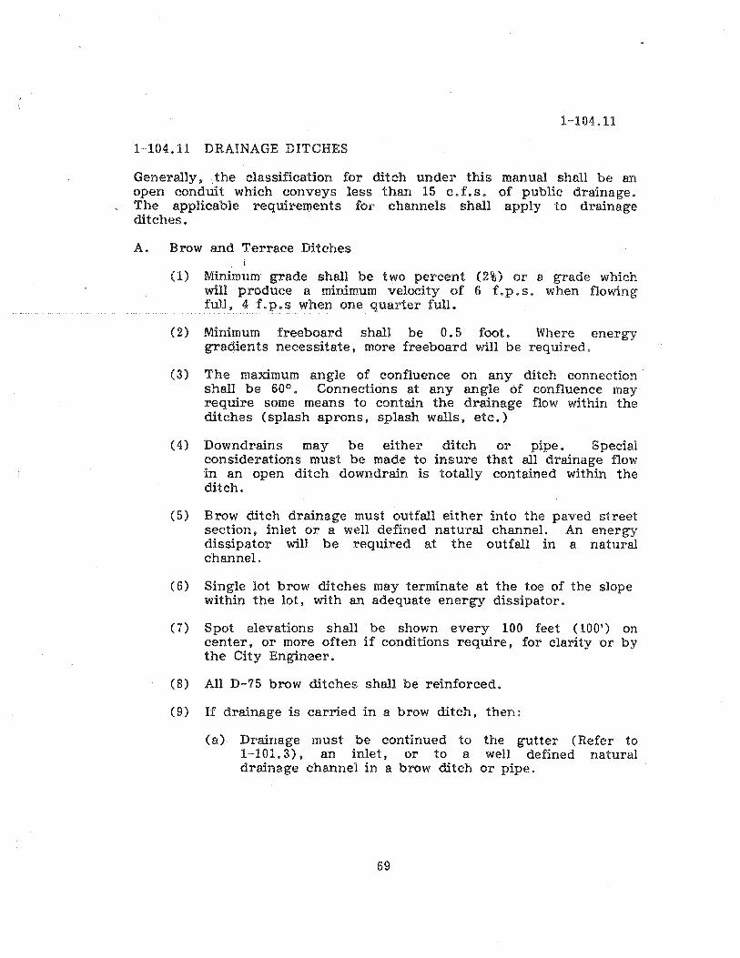
1-104.11
1-104.11 DRAINAGE DITCHES
Generally, the classification for ditch under this manual shall be an open conduit which conveys less than 15 c. f. s. of public drainage. The applicable requirements for channels shall apply to drainage ditches.
A. Brow and Terrace Ditches
(1) Minimum grade shall be two percent (2%) or a grade which will produce a minimum velocity of 6 f.p.s. when flowing full. 4 f.p.s when one quarter full.
(2) Minimum freeboard shall be 0.5 foot. Where energy gradients necessitate. more freeboard will be required.
(3) The maximum angle of confluence on any ditch connection shall be 600 • Connections at any angle of confluence may require some means to contain the drainage flow within the ditches (splash aprons, splash walls t etc.)
(4) Downdrains may be either ditch or pipe. Special considerations must be made to insure that all drainage flow in an open ditch down drain is totally contained within the ditch.
(5) Brow ditch drainage must outfall either into the paved street section. inlet or a well defined natural channel. An energy dissipator will be required at the outfall in a natural channel.
(6) Single lot brow ditches may terminate at the toe of the slope within the lot, with an adequate energy dissipator.
(7) Spot elevations shall be shown every 100 feet (100') on center. or more often if conditions require, for clarity or by the City Engineer.
(8) All D-75 brow ditches shall be reinforced.
(9) If drainage is carried in a brow ditch, then:
(a) Drainage must be continued to the gutter (Refer to 1-101.3). an inlet, or to a well defined natural drainage channel in a brow ditch or pipe.
69
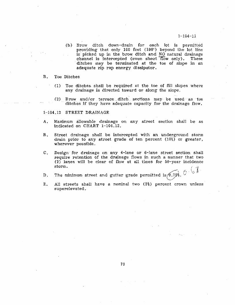
1-104-11
(b) Brow ditch down-drain for each lot is permitted providing that only 100 feet (100') beyond the lot line is picked up in the brow ditch and NO natural drainage channel is intercepted (even sheet IiOw only). These ditches may be terminated at the toe of slope in an adequate rip rap energy dissipator.
B. Toe Ditches
(1) Toe ditches shall be required at the toe of fill slopes where any drainage is directed toward or along the slope.
(2) Brow and/or terrace ditch' sections may be used as toe ditches if they have adequate capacity for the drainage flow.
1-104.12 STREET DRAINAGE
A. Maximum allowable drainage on any street section shall be as indicated on CHART 1-104.12.
B. Street drainage shall be intercepted with an underground storm drain prior to any street grade of ten percent (10%) or greater. wherever possible.
C. Design for drainage on any 4-lane or 6-1ane street section shall require retention of the drainage flows in such a manner that two (2) lanes will be clear of flow at all times for 50-year incidence storm. . ( "~
D. The minimum street and gutter grade permitted is &. 0 . ,<i .
E. All streets shall have a nominal two (2%) percent crown unless superelevated.
70

~LI .. '" 1111
1.2
t.C tU tU
CJ'
0.11
0.5
M
REV.
. I
CHART 1-104.12
I I.j I I 4 S~'I'.tlQ
I)ISOU~ (c:. F: So) ONE SItlE
Givef'l' Q It 10 522...5"'" eMf! CJlVIiS: Dclll" l 0.4. 'ft1D!:i1y Z ~.4 (!ilL
CITY OF SAN DIEGO ... DESIGN GUIDE
GUTTER AND ROADWAY DISCHARGE - VELOCITY CHART
70A
SHT. NO.
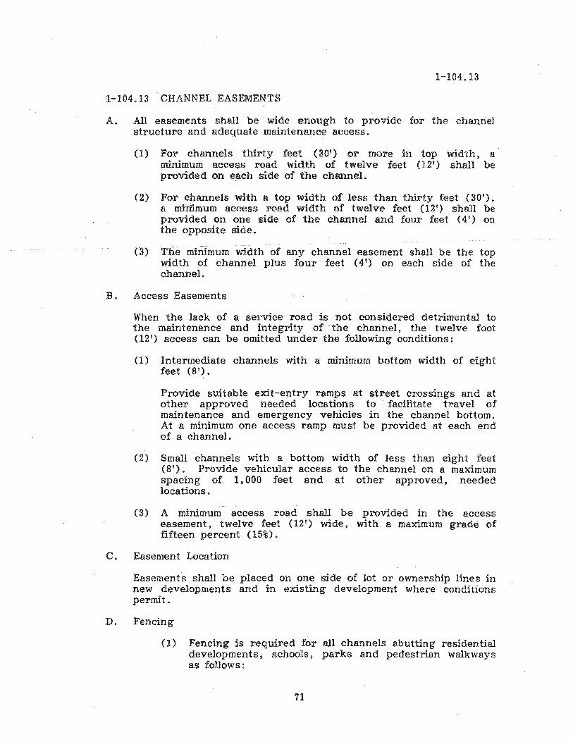
1-104.13
1-104.13 CHANNEL EASEMENTS
A. All easements shall be wide enough to provide for the channel structure and adequate maintenance access.
(1) For channels thirty feet (30') or more in top width, a· minimum access road width of twelve feet (12') shall be provided on each side of the channel.
(2) For channels with a top width of less than thirty feet (30'), a mimmum access road width of twelve feet (12') shall be provided on one side of the channel and four feet (4') on the opposite side.
(3) The minimum width of any channel easement shall be the top width of channel plus four feet (4') on each side of the channel.
B. Access Easements
When the lack of a service road is not considered detrimental to the maintenance and integrity of the channel, the twelve foot (12') access can be omitted under the following conditions:
(1) Intermediate channels with a minimum bottom width of eight feet (8').
Provide suitable exit-entry ramps at street crossings and at other approved needed locations to facilitate travel of maintenance and emergency vehicles in the channel bottom. At a minimum one access ramp must be provided at each end of a channel.
(2) Small channels with a bottom width of less than eight feet (8') . Provide vehicular access to the channel on a maximum spacing of 1,000 feet and at other approved. needed locations.
(3) A minimum access road shall be provided in the access easement, twelve feet (12') wide, with a maximum grade of fifteen percent (15%).
C. Easement Location
Easements shall be placed on one side of lot or ownership lines in new developments and in existing development where conditions permit.
D. Fencing
(1) Fencing is required for all channels abutting residential developments. schools. parks and pedestrian walkways as follows:
71

1-104.13
(a) Fencing is required for all concrete lined or rip rapped channels where the design frequency storm provides a velocity which exceed 5 feet per second and two feet (2') in depth or a combination thereof for a factor of ten (10). (This does not include brow ditches).
(b) Fencing is required for all unlined channels steeper than 4: 1 where the design frequency storm provides a velocity which exceeds five feet (5') per second and two feet (2') in depth or a combination thereof for a factor of ten (10).
~2) Six foot (6') high chain link fence shall be installed on both ~ides of the channel easement, with gate openings at all access points. (Twenty foot (20') gates - 1, 000 feet on center; four-foot (4') gates - 500 feet on center or portIon thereof for maintenance or emergency access.
(3) Fencing shall be located a minimum of six inches (6") inside the easement boundary lines unless otherwise approved.
(4) Fencing Material:
(a) All new fences shall be chain link, a mImmum of six feet (6') in height with a top rail. (Steel fence must be galvanized) .
(b) Existing five foot (5') high chain link fences may remain if they are in good condition. (No rust).
(c) Existmg four foot (4') high fences shall be replaced with six foot (6') high chain link fences.
(5) All bridge crossings shall be fenced.
72
1-104.14
1-104.14 MANNINGS ROUGHNESS COEFFICIENTS
A. TABLE 1-104.14A Design values for Mannings Roughness Coefficient (n)
B. CHART 1-104.14B Nomograph for Solution of Ma.nning Equation
73
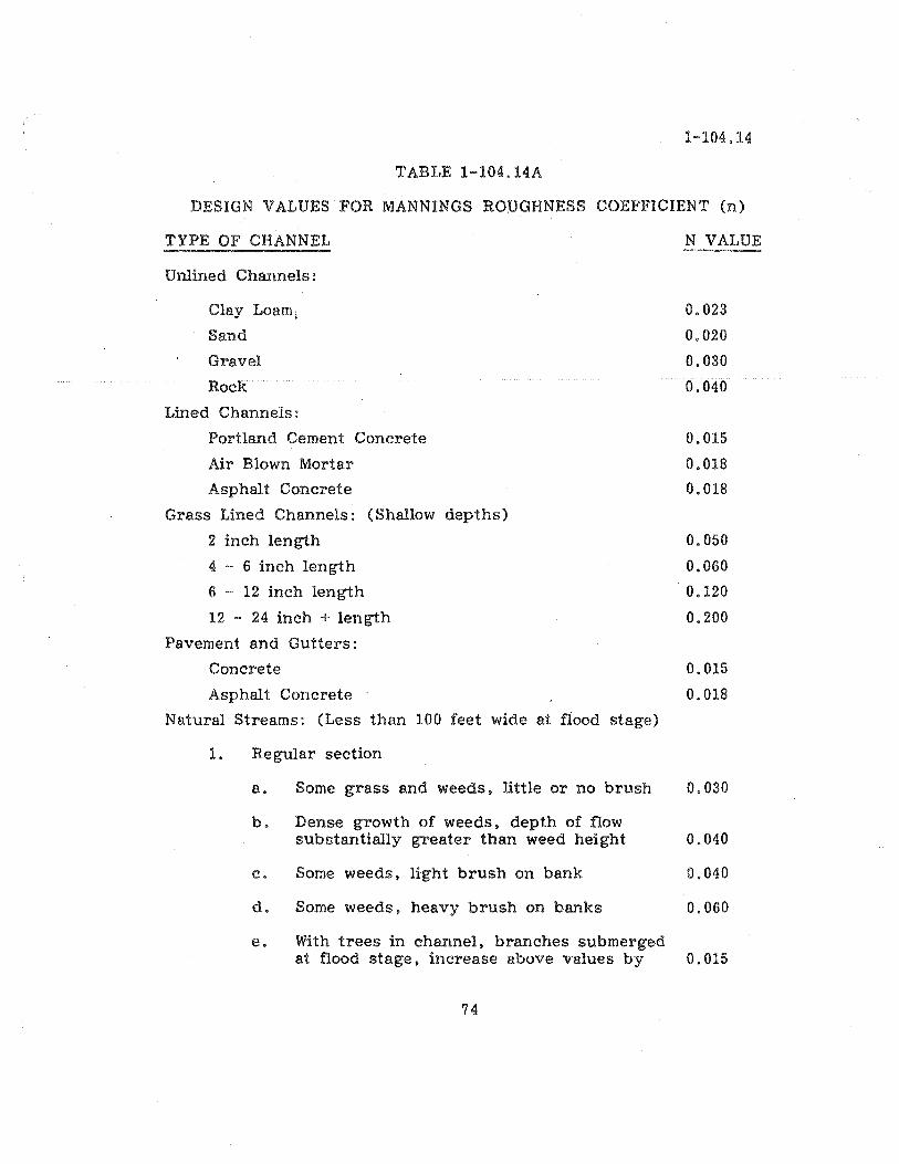
1-104.14
TABLE 1-104.14A
DESIGN VALUES FOR MANNINGS ROUGHNESS COEFFICIENT (n)
TYPE OF CHANNEL
Unlined Channels:
Clay Loami
Sand
Gravel
Rock
Lined Channels:
Portland Cement Concrete
Air Blown Mortar
Asphalt Concrete
Grass Lined Channels: (Shallow depths)
2 inch length
4 - 6 inch length
6 - 12 inch length
12 - 24 inch + length
Pavement and Gutters:
Concrete
Asphalt Concrete
Natural Streams: (Less than 100 feet wide at flood stage)
1. Re gular section
N VALUE
0.023
0.020
0.030
0.040
0.015
0.018
0.018
0.050
0.060
0.120
0.200
0.015
0.018
a. Some grass and weeds, little or no brush 0.030
b. Dense growth of weeds. depth of flow substantially greater than weed height 0.040
c. Some weeds. light brush on bank 0.040
d. Some weeds. heavy brush on banks 0.060
e. With trees in channel. branches submerged at flood stage» increase above values by 0.015
74

TABLE 1-104.14A (Continued).
2. Irregular section. with pools. slight channel meander increase all values listed in 1. Regular
1-104.14
Section. by 0.015
Flood Plains: (adjacent to natural streams)
1. Pasture, no brush j
a. Short grass
b. High grass
2. Cultivated areas
3.
4.
5.
6.
7.
8.
a. No crop
b. Mature row crops
c. Mature field crops
Heavy weeds. scattered brush
Light brush and trees
Medium to dense brush
Dense willows
Cleared land with tree stumps. 100-150 per acre
Heavy stand of timer, little undergrowth
a. Flood depth below branches
b. Flood depth reaches branches
75
0.030
0.040
0.040
0.040
0.050
0.050
0.060
0.090
0.170
0.060
0.110
0.140

10
'* II: III
• 'I'
..... e ... ... II .... C 4 -~ ::;) s ... C C &Z:
t .. 0 ...
e. ...I ::;)
C « e LO )- . 1 ::s:: .111
:r
•• .5
.4
.3
.2
.10
REV.
EXAMPLE (See Dotted Lines)
Given: R:: 2 ft. S::. 0.005 n :: 0.02
::Find V:: 8.35 ft IIUIC.
.0001
.ooot
.coos
~ .0004
I .COM .000. - .001
0 0 ....
.002 e·e ... e.. til .00s ...... A. .004
..... til . 00.. til
CHARi 1-104.149
.. .. :; .. .. It .. .. ..
V. 1IeIoeIlylft .., .... ~
·111' " ........... -tfici<!<lt 4II-""to 10 _~i<II 1111>114_ of eII<o_l.
!II·~ie_i"'"' S. $'- to .., 1>114 loot
.01
m
.Q4
.011
.011 .ooe <p e • .... .01 ...... oM C - .at
&AI IL .os 0 .Q4
...I oM «#)
.0111
.10
.2
• 1
-f/II II til ....
)-.... <.)
0 ..J &1.1 >-
1I
2
1.0
.11
•• .r
•• • 11
FEDERAL HIGHWAY ADMINISTRATION AUGUST .951
CITY OF SAN DIEGO ... DESIGN GUIDE
NOMOGRAPH FOR SOLUTION OF MANNING EOUAT ION
76
SHT. NO.
1-104.15
1-104.15 DESIGN GUIDES
A. FIGURES 1-104.15A Typica.l Channel Plan
B. FIGURES 1-104.15B Typical Channel Profile
77

REV.
I I I
I I I I
I I • 92
FIGURE 1-104.15A
CURVE OATA A. S" 29' 20f R' 1000' 1. 8 is.SO'
~ 'CONCRETE LINED DRAINAGE CHANNEL
BEAUTY
P. L. 1280
For details see D-71
HEIGHTS
For Profile See Figure 1-104.15B
12. •
.fo---........i---F ..
. 10 15
,
.. ..
CITY OF SAN DIEGO - DESIGN GUIDE SHT. NO.
TYPICAL CHANNEL PLAN
78

FIGURE 1-104.1SB
«
N,W BP EI 11:20 23 MS .. Lu. on Rtn 0 Is.
1
~
t± i I ! CD
.~L= I I~
J 1-;
I .. Iv .. Gr und lin. - III
~ i-- i-- ---1 00 ""
V-' rn '''''','w 1- Wat r •. r Q :z:
..J -'"
(..J ':: Itt> :. ~ .. , .....
1V1= I'
~ .. .~ . :r
ir" , I'"' <lit
In ert r---:" .1:>' I
I ()
~pt ~ I .... -c Pr file of SIC Ore nl ~o r.el '?i - m
lad lace in! Ito Is@. lulv 11 i,,11 I [III
I C
!1~ s~ I1gr I' =4(' ~ - \feM I : 6' .
I .;;
a ~ ., ~ ~
~
For Plan See Figure 1-104.15A
REV. CITY OF SAN DIEGO - DESIGN GUIDE SHT. NO.
TYPICAL CHANNEL PROFILE
79

APPENDIX I
RATIONAL METHOD
Watersheds Less than 0.5 Square Mile
Method of Computing Runoff
Use the Rational Formula Q :::: CIA where:
Q. is the peak rate of flow in cubic feet per second.
C is a runoff coefficient expressed as that percentage of rainfall which oecomes surface runoff.
I is the average rainfall intensity in inches per hour for a storm 'duration equal· to the time of concentration (T ) of the contributing d
. c . ramage area.
A is the drainage area in acres tributary to design point.
(1) Runoff Coefficient. C
Appendix I-A lists the estimated coefficients for urban areas.
For urban areas select an appropriate coefficient for each type of land use from Table. 2. Appendix I-A. Multiply this coefficient by the percentage of the total area included in that class. The sum of the products for all land uses in San Diego County is the weighted runoff coefficient.
(2) Rainfall Intensity, I
Intensity - duration - frequency curves applicable to all areas within San Diego County are given in Appendix I-B.
(3) Time of Concentration. Tc
The time of concentration is the time required for runoff to flow from the most remote part of the watershed to the outlet point under consideration.
80

Methods of calculation differ for natural watersheds (non-urbanized) and for
urban drainage systems. Also, when designing storm drain systems, the
designer must consider the possibility that an existing natural watershed
may become urbanized during the useful life of the storm drain system.
(a)
(b)
Natural watersheds: Obtain T from Appendices I-C and I-D. c
Urban drainage systems: In the case of urban drainage systems, the
time ~f concentration at any point within the drainage area is given
by:
T ::: T. + Tf where c 1
T. is the inlet time or the time required for the storm water to flow 1 .
to the first inlet in thesystem. It is the sum of time in overland flow
across lots and in the street gutter.
T f is the travel time or the time required for the storm water to flow
in the storm drain from the most upstream inlet to the point in
question.
Travel Time, T f' is computed by dividing the length of storm drain by
the computed flow velocity. Since the velocity normally changes at
each inlet because of changes in flow rate or slope, total travel time
must be computed as the sum of the travel times for each section of
the storm drain.
The overland flow component of inlet time, T., may be estimated by 1
the use of the chart shown in Appendix I-E. Use Appendix I-F to
estimate time of travel for street gutter flow.
81

TABLE 2
RUNOFF COEFFICIENTS (RATIONAL METHOD)
DEVELOPED AREAS (URBAN)
Land Use
Residential:
Single Family
Multi-Units
Mobile Homes
Rural (lots greater than 1/2 acre)
Com mercia! (2) 8096 Impervious
Industrial (2) 9096 Impervious
NOTES:
(1) Type D soil to be used for all areas.
coeffic::ien~ C Soil Type n
D
.55
.70
.65
.45
.85
.95
(2) Where actual conditions deviate significantly from the tabulated imperviousness values of 8096 or 9096, the values given for coefficient C, may be revised by multiplying 8096 or 9096 by the ratio of actual imperviousness to the tabulated imperviousness. However, in no case shall the final coefficient be less than 0.50. For example: Consider commercial property on D soil.
Actual imperviousness ::: 5096
Tabulated imperviousness ::: 8096
Revised C 50 0.85 0.53 :: 80 x :::
82
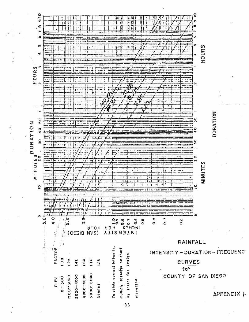
.... ..;;..,..;!: .... : ... p .. IIiI:I -~. '- •
.... •• t ... f ~ ~ __ ,
.. ~-:r.i:;:: t+ ~+--an ... , t::l : I-l; i ~; tr nl .' r -: I ~ . .;.......j.. t+- .. !-tt-H-....;...,f..J -- _.
~..... ; I .;;; I . I; ; .. ; t ... ; :.....;....l.:. ...... -:.; ..... _.:t.=;~...;:;r;:-;.-..;i::
r-:.:: ~ .::: i.; Jt;.:..!.!LU.':" -t-:":- .:... ..... : .... - .;;~_
.... -i"",.. ..
------
f--I ...... _ .• ·rtfl/',tl/'·-/ ~-yi--='I-'';' J.~ • :. v '-7":"" -TT -T, • '.
!---jr:- -r I i I •
. It ~,......, 1'/ 1/ '/ ; .,' 'f t. ! ""
j ,.. '/' I I I I II
I • N <f" if",
(,. ~nOH
(O~3IQ N~S)
",,, c:/ .,.: -
.---i ------==+--;0
.• ;-1<'.1 en -.;-.....;...:...., w t~ Z ~
RAINFALL
2 o
0 ... t> 0 <II: Ill') N 0 0 11'1 I.t.. 0 N o:r II:! "": ~
:::: ... u
'" .t:: C eo. ... C II:
0
II: uo ... ..
INTE:"dSITY .... DURATION- FREQUENC
CURVES .... ..: ....
0 0 0 0 :> 0 0 0 0 0 I.IJ 0 0 0 0 0 ..I '!2 1"1 <er Ill') 'II; ... aM 1 I I I I a::
0 0 0 I.IJ 0 0 0 0 0 0') 0 0 0 0 w ~ 1"1 <er Ill') Q
- ... "15
Y !: .. .. ... .. 6:) ... II: 0 ... y c .. C II: CI 1:1 -'; .!: y .... - .!:- 1:1
U A -0 .::: lI>
eo ::) "" .. -... E .II> IiiI
fo~
COUNTY OF SAN DIEGO
APPENDIX I ..
83

, ,
IOIJ
&: t.)t4.£ I"'f" I UIII
(/1 9L ..1'\ • .Y85'
H: '" "iI 1 " lC III lime: 1:)1 &:&:Jnt:c:nlraf"c/7 (I n hours J L .. Len91h cl'·waler.slu .. d L ,'n milts) II" /)/l'l'eren&:e in elevalti::Jn 0./""9 ( I () feet')
e//eeflj.-e slp.t:Je line (See Iippel1dix 1·$)
L. Mlle$ reel
~=---=--=-== =---=-1 I NOTE: • ADD TEN MINUTES TO
UCOMPUTED TIME OF CONj CENTRATION. :o=...-=---=--=-==---=---_::!.!
2IJIJt) I!JOt) IIUiO 14/J/J
?tJ
1-1--&0
20 18
1$
/¢
/2
H L
SAN Dl EGO COUNTY DEPARTMENT OF SPECIAL DISTRICT SERVICES
DES I GN MANUAL
NOMOGRAPH FOR DETERMINATION OF TIME OF CONCENTRATIOf\; (7c)
FOR NATURAL WATERSHEDS
APPROVED ....... ~ ... C·· .. /,··,. .. ,,-c-;-..... , DATE _____ _ APPENDIX
84

-/
~~
"-
Wa.f~,..slu!d D/Vld.e: "'\ ---- ~
..... ~-------------------------- L
T' H
!
SAN DIEGO COUNTY
DEPARTMENT OF SPECIAL DISTRICT SERVICES
DESIGN MANUA~ .. APPROVED /.," , -I, ........ t' k '-4 rz ~
; :g
85
COMPUTATION OF EFFECTIVE SLOPE FOR NATURAL WATERSHEDS
I. DATE ___ ..l.,.,.".._ APPENDIX
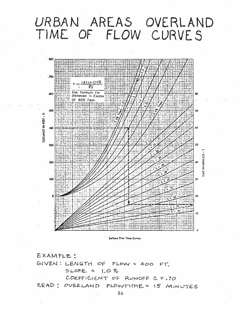
UR8 N TiME
AREAS F FL W
500 Q
I
S ...
* 400 .... u Z c( ... .... 25
300
EXAt-/\ ?L.E.. :
GiVEN: OF FLo\AI
SLOPE...:. I. 0 ~o
COE.Ff I c"i E.N T
OVE:.RLAND
OVERLAN C RV
50
... I
.." W
:; 40 Z
~ Z w :: ;::
30
400 FI ..
c. :::; .. 70
15 M(NUTE.S

w ! 4
.&1l ... , W W 41!:
t ~ 2
~L8 14
III
U
AC
o.t o.t CD'
0.'
Q.!
0'-
REV.
. I
CHART 1-104.12
I 1.1 I I 1\" 1'8'10
OISOolA~ (c. F: s.) ONE SIDE
G; .. ~I'l: Q It 10 S. 2..5 "'4 Chorl 'II'U:· Oepu\ It 0.4. ~ty a 4.4 t~&.
CITY OF SAN DIEGO - DESIGN GUIDE
GUTTER AND ROADWAY
DISCHARGE - VELOCITY CHART
87
SHT. NO.
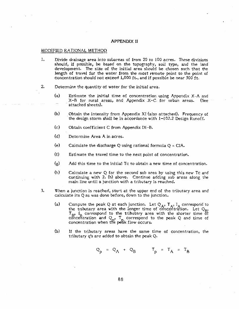
APPENDIX II
MODIFIED RATIONAL METHOD
1. Divide drainage area into subareas of from 20 to 100 acres. These divisions should, if possible, be based on the topography, soil type, and the land development. The size of the initial area should be chosen such that the length of travel for the water from the most remote point to the point of concentration should not exceed 1,000 ft., and if possible be near 500 ft.
2. Determine the quantity of water for the initial area.
(a) Estimate the initial time of concentration using Appendix X-A and X-B for rural areas, and Appendix X-C for urban areas. (See attached sheets).
(b) Obtain the intensity from Appendix XI (also attached). Frequency of the design storm shall be in accordance with 1-102.2 Design Runoff.
(c) Obtain coefficient C from AppendIx IX-B.
(d) Determine Area A in acres.
(e) Calculate the diSCharge Q using rational formula Q :::: CIA.
(f) Esti mate the travel time to the next point of concentration.
(g) Add this time to the initial Tc to obtain a new time of concentration.
(h) Calculate a new Q for the second sub area by using this new Tc and continuing with 2. (b) above. Continue adding sub areas along the main line until a junction with a tributary is reached.
3. When a junction is reached, start at the upper end of the tributary area and calculate its Q as was done before, down to the junction.
(a)
(b)
Compute the peak Q at each junction. Let Q A' T A' I correspond to the tributary area with the longer time of concentr~ion. Let QS' T S' IS correspond to the tributary area with the shorter time of concentration and Q ,T correspond to the peak Q and time of concentration when tH'e ~k flow occurs.
If the tributary areas have the same time of concentration, the tributary q's are added to obtain the peak Q.
88

(c) If the tributary areas have different time of concentration, the smaller of the tributary Q's must be corrected as follows:
(1) The usual case is where the tributary area with the longer time of concentration has the larger Q. In this case, the smaller Q is corrected by a ratio of the intensities and added to the larger Q to obtain the peak Q. The tabling is then continued downstream using the longer time of concentration.
IA Qp ::: Q A + QB IS
(:2) In some cases, the tributary area with the shorter time of concentration has the larger Q. In this case, the smaller Q is corrected by a ratio of the times of concentration and added to the larger Q to obtain the peak Q. The tabling is then continued downstream using the shorter time of concentration.
TS Qp ::: Q S + QA TA
89

DRAINAGE STUDY
(Example of Modified Rational Method)
AREA ACRES A IIC" CA ~ CA --A-I 198 198 .55 109 109 A-2 52 250 .55 29 138 A-3 137 387 .55 75 213 A-4 86 473 .55 47 260 A-5 76 549 .6 46 306
INITIAL AREA A-I:
A = 198 acres, L = 5000', llH = 1127 - 680 = 447', T = 10 + 14 = 24 min, c ;50 = 2.1 in/hr., Q50 = 109 x 2.1 = 229 cfs, Length of next reach = 1700',
slope = 40'/1700' = .0235
Say 2.5% max., max velocity in improved section: assume future channel
extension to this point (6 1 bottom 1.5: 1 sides)
b8/ 3 = 119 S; : 0.158, K': ii~ ~ :~~~ = 0.17, D/b = .256, D = 6 x .256 =
1.5, A = 8.25 x 1.5 = 12.4 ft 2, V = 229/12.4 = 18.5 ft/sec
Time in reach - 1700 = 1.5 min. - 60 x 18.5
AREA A-2:
~ CA = 138, Adjusted Time = 24 + 1.5 ::: 25.5 min.
150 = 2.05 in/hr, Q50 = 138 x 2.05 ::: 283 cfs
Length of next reach::: 1600 1, Slope = 1igo ::: 2.5%, Use 3% max (assume future
improved 61 bottom 1.5:1 concrete section) K'::: i¥~ ~ :~j4 ::: .196, D/b = .276,
o = .276 x 6 ::: 1.66' A = 8.49 x 1.66 ::: 14.1 ft2, V = I~:l = 20.1 ft/sec, 1600 _ .
Time in reach = 60x20.1 - 1.3 mln.
90
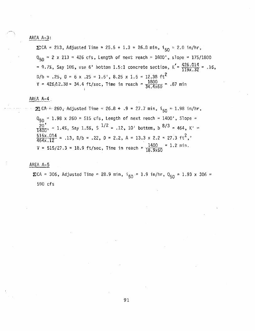
AREA A-3:
CA = 213, Adjusted Time = 25.5 + 1.3 = 26.8 min, ;50 = 2.0 in/hr,
QSO = 2 x 213 = 426 cfs, Length of next reach = 1800', slope = 175/1800
= 9.7%, Say 10%, use 6' bottom 1.5:1 concrete section,
D/b = .25, D = 6 x .25 = 1.5 1, 8.25 x 1.5 = 12.38 ft2
_ 1800 V = 426fi2.38= 34.4 ft/sec, Time in reach - 34.4x60 =
AREA A-4
K/= 426.014 = 16
119x.32 • ,
.87 min
~CA ~ 260, Adjusted Time = 26.8 + .9 = 27.7 min, i50 = 1.98 in/hr,
QSO = 1.98 x 260 = 515 cfs, Length of next reach = 1400', Slope =
~I = 1.4%, Say 1.5%, S 1/2 = .12., 10' bottom, b 8/3 = 464, KI = ~~~~:~~4 = .13, D/b = .22, D = 2.2, A = 13.3 x 2.2 = 27.3 ft2,'
V = 51S/27.3 = 18.9 ft/sec, Time in reach = 1~:~~60 = 1.2 min.
AREA A-5
IleA = 306, Adjusted Time = 28.9 min, ;50 = 1.9 ;n/hr, QSO = 1.93 x 306 =
590 cfs
91

o ....
~--- .'"'--.., -
• ~
"
, ,r <,... (
EI H

p. I-A-3
p. I-A-14
APPENDIXm
SCS METHOD
Procedure for Calculation of Runoff Curve Number (CN)
1. Locate basin on 1 :2000 scale USGS topographic map(s).
2. Using a I/2-lnch or I-inch grid O/2-inch for areas less than .5 square miles) on a translu-cent overlay sheet, trace the basin boundary and other significant information from the topographic maps.
3. Locate basin on I :2000 scale Soil Conservation Service (SCS) hydrologic ground cover and soil group maps available at the offices of the Department of Sanitation and Flood Control.
4. Overlay the grid sheet onto the ground cover and soil group maps; for each map record appropriate group cover (OB, NC-, DL, etc.) and soil group (A, B, C, or D) at each grid intersection within the basin.
5. For each combination of ground cover/soil group (OB/ A, NC/B, NC/D, etc.) count and record the number of grid intersections where that combination occurs.
6. Compute the total number of grid intersec-tions within the basin. For a I-inch grid, each intersection represents 1 square inch on the maps, and the total area of the basin is found by scale conversion; for l/2-inch grid, each intersection is 1/4 square inch. Compute the total area of the basin.
7. By field inspection, determine the hydrologic conditions which exist in the basin for each type of ground cover.
93
to Example
APP-B-l1
APP-B-7
APP-B-5 APP-B-6
APP-B-7
APP-B-7
APP-B-7
APP-B-8 APP-B-9 Col. 2

Hydrology Manual
p. I-A-14
p.I-A-6 p.I-A-7
p. I-A-17 to
p. I-A-2.5
Procedure for Calculation of Runoff Curve Number (CN) (Continued)
Procedure Stee No.
8. For each ground cover/soil group combination i compute the fraction of the total area repre-sented by that combination by the ratio of the number of grid intersections counted in Step 5 to the total number of grid intersections counted in Step 6.
9. For each ground cover/soH group/hydrologic condition combination, select the appropriate runoff curve number for antecedent moisture Condition Z (CNZ)'
10. Compute the partial CN2 for each ground cover/soil group combination by the product of area fraction of each combination from Step 8 and the selected CN2's from Step 9.
II. Sum the partial CN,iS from Step 10 to obtain the CN2 for the en ire basin.
12. For future land uses modify existing ground cover designations and use same procedures.
13. Ii stream bed is alluvial fill with deep group "A" solIs (sands and gravels), the 'CN adjust-ment procedure should be considered.
94
to Example on Page
APP-B-9 Col • .5
APP-B-9 Col. 4
APP-B-9 Col. 6
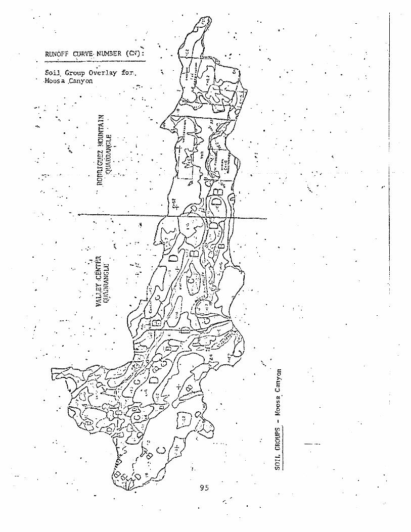
....
'.
.... RUNOFF QJRVE, NUMBER (C~):
-Soil. Group O;eTlay fOl\~ '\
,1010053. ,Canyon
", .
,'. ..," ..
','
'.
-,
-"0·-
111' ....
.. : . .,
95
"
." .
.. ..
°0
. ".
'.
• !
"
c:: 0 >.. c:: 11$ u 11$' 11\ 0 0 :.z
en Q.. ::;:, 0 c:: t.:l
..:l .... 0 en

~ I
:.
:.
" , I:
!: !. I, " i; ,j , .. I. Ii ,.
" I ,
:-
~ "U , W I 0\
: .\
! VALLEY CENTER QUADRANGLE .
'. '.1 P ! .. .. . .. '"' .' .. '
HYDROLOGIC GROUND COVER -:-: LAN!} USE , .. .
Moosa Canyon
, ., OCl
~ <: Ii ~ 0 Z
.f • :1g ·0 'TI
II! U. 'TI .pO. ~ n 8 H) 0
o -< ~
MOUNTAIN >1 ~ ni >1 3;:, ,QUADRANGLE o t""'
~ .". ' ... '. f;: r; II! P-
" .. '.! n c: m ;u
.' ~ ~ ,,"",.
,,<' .2 -, • 0 .;::3 • '-oJ
I".

R~TNOFF CURVE NUMBER (CN):
: ... ~.: .... : . -'- ._._ ..... _. _ .. Tabulation of Ground Cover/Land Use .. ' .. -~ -~ ... --; ........... ~ ........ ''''''''' ' . and Soil Group designations for 1" grid'" :-' -, .~'- '-:' ,~."~ -
• : g'
on 1:2000 scale map~ -..
Moosa Canyon Creek, Above Turn,er • , .
,Ground Number of int~rsecti~~s~ 1-,., Cover/ for each Soil Group t
• . .. 'Land' " -Use A B i <:: D -,.~ 1----: , " -CR 1 . . - • !- .
.. IP 1
, ~
1 ,
Of 1 :2 ':2 ........ < .....
DL 1 " ,
..:.. - . AG . 7 .2 S -BC 3· 1.2 4 .
, , NC .~ 6 .:; --' OS 6 8 4- . . ,
.. .. WO 1 I

RIVER NAME· . PAGE OF
DATE HYDROLOGIC CONDITION
BY LAND GOOD FAIR POOR USE 3 2 1
CODE A-I BlC-ID AIBICID AIB!CID
FALLOW STRAIGHT ROW CR 1
ROW CROPS STRAIGHT ROW CR 2 i
ROW CROPS CONTOURED CR 3
SMALL GRAIN STRAIGHT ROW CR 4
SMALL GRAIN CONTOURED CR 5
CLOSE SEEDED STRAIGHT CR 6
CLOSE SEEDED CONTOURED CR 7
IRRIGA TED PASTURE IP 8
WATER SURF ACES (DURING FLOODS) WA 9
ORCHARDS EVERGREEN OE 10
URBAN LOW DENSITY DL 12
URBAN MEDIUM DENSITY DL 13
URBAN HIGH DENSITY DL 14
COMMERCIAL INDUSTRIAL DL 15
ANNUAL GRASS AG 16
BROADLEAF CHAPARRAL BC 17
MEADOW ME 18
NARROWLEAFCHAPARRAL NC 20
OPEN BRUSH OB 20
PERENNIAL GRASS PG 21
WOODLAND GRASS WG 22
WOODS WO 23
BARREN BA 24
TURF TU 25
FARMSTEADS FS 26
ROADS (DIRT) RD 27
ROADS (HARD SURFACE) RD 28
98
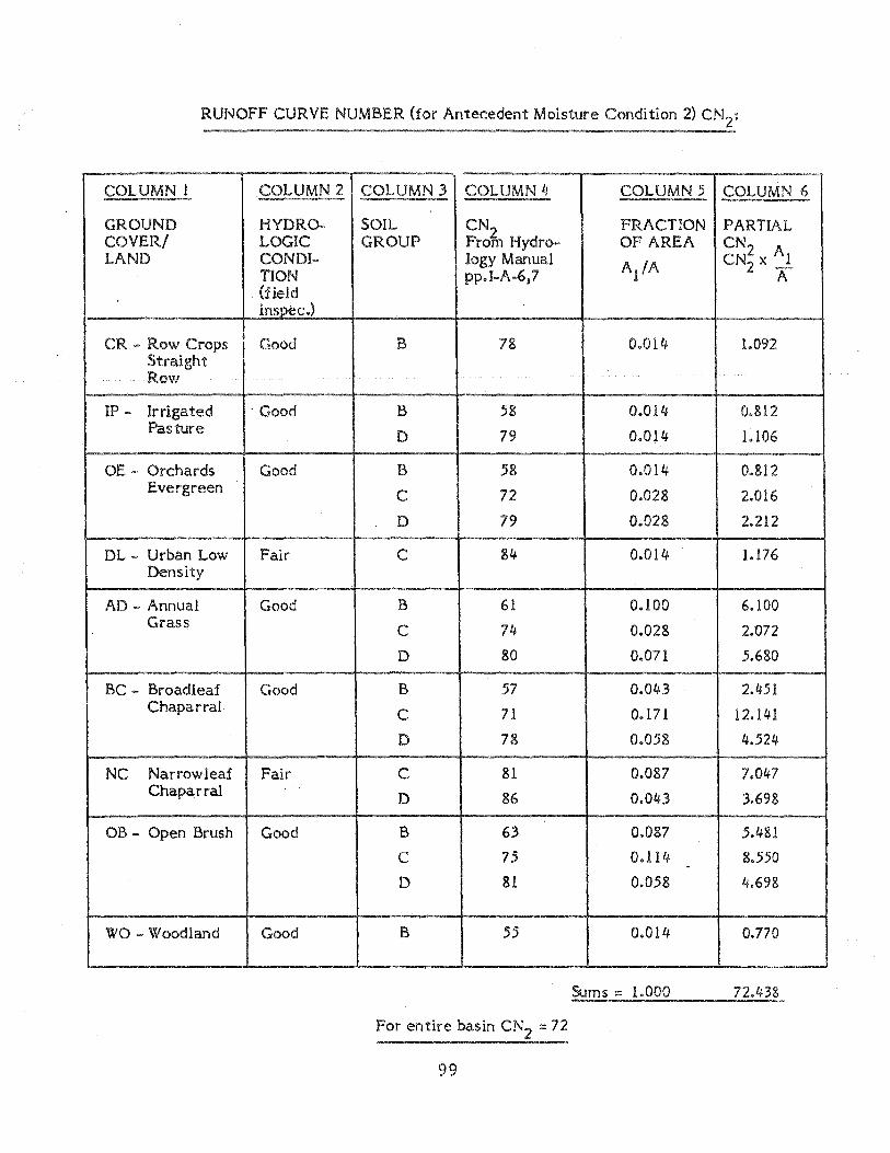
RUNOFF CURVE NUMBER (for Antecedent Moisture Condition 2)
COLUMN 1 COLUMN 2 COLUMN 3 COLUMN 4 COLUMN .5 COLUMN 6
GROUND HYDRO- SOIL CN2 FRACTION PARTIAL COVER! LOGIC GROUP From Hydro- OF AREA CN LAND CONDI- logy Manual
A/A CN~ x Al
TION pp.I-A-6,7 A . (field
inst)ec.)
CR - Row Crops Good B 78 0.014- 1.092 Straight Row
IP - Irrigated . Good B 58 0.014- 0.812 Pasture D 79 0.014 1.106
OE - Orchards Good B 58 0.014 0.812 Evergreen
C 72 0.028 2.016
D 79 0.028 2.212
DL - Urban Low Fair C 84 0.014 1.176 Density
AD - Annual Good B 61 0.100 6.100 Grass
C 74 0.028 2.072
D 80 0.071 .5.680
BC - Broadleaf Good B 57 0.043 2.451 Chaparral
C 71 0.171 12.141
D 78 0.058 4.524
NC Narrowleaf Fair C 81 0.087 7.047 Chaparral D 86 0.043 3.698
OB - Open Brush Good B 63 0.087 .5.481
C 75 0.114 8.550 -D 81 0.058 4.698
WO - Woodland Good B .55 0.014 0.770
Sums::: 1.000 72.438
For entire basin ::: 72
99

Procedure for Calcutation of Lag Time and Time to Peak (See p. APP-B-l1)
Reference in Hydrology
Manual
p. I-B-1
p. 1-8-1
p. I-B-l,2
p. I-B-1
p. I-C-IO
Procedure Step Number
1. Locate basin boundary on I' :: 2000' scale topographic map.
2. Compute: j
a. Drainage area, A, square miles. (See p. APP-B-7)
b. Length of longest watercourse, L, in miles.
c. L ,length along longest watercourse in miles, m~asured upstream to point opposite center of area.
3. Compute overall slope, S:
a. Eh ::: elevation of most remote point on
watercourse.
b. E 1 :: elevation at outlet.
c. ::: 2100-100
9.45 ::: 121 ft per mi.
4. By field inspection select basin n factor, the average of the Manning's n values of the watercourse and tributaries.
5. Compute Lag time:
Lag:: 24 n Lx Lc .38 ::: (24) (.050) (9.45)(4.1) .38
S 121
Lag:: 1.94 hr.
6. If no unit hydrograph has been developed for the basin based on recorded rainfall-runoff data, I,lse Soil Conservation Service (SCS) dimensionless unit hydrograph for which the time to peak is:
T ::: 0.862 Lag ::: (0.862)(1.94) ::: 1.67 hr. p
100
Computed Value
A::: 10.0 mi. 2
L ::: 9.45 mil.
L ::: 4.1 mi. c
Eh ::: 2140 ft.
El ::: 1000 ft.
S :: 121 ft/mi.
n::: 0.050
Lag ::: 1.94 hr.
T ::: 1.67 hr. p
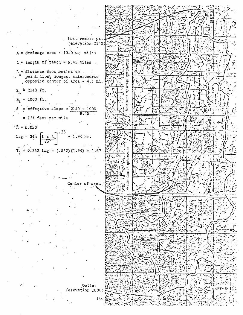
Mos t :remote pt, (elev~tion 2140)
A ::: drainage area :::: 10·,0 sq, mi 1 es
L = length of ' reach :::: 9.45 miles
L '" c distance from .outlet to point.. alon'g longes"t wat.ercourse opposite center of area'" 4.1 mi.,
:I: 2140 ft.
S = effective slope '" 2140 - 1000 9.45
= 12l feet pel' ~le
. n = D .050
0.862 Lag ""' (.862) (1.94) '" , .
Center '!' .
. '
e' ..
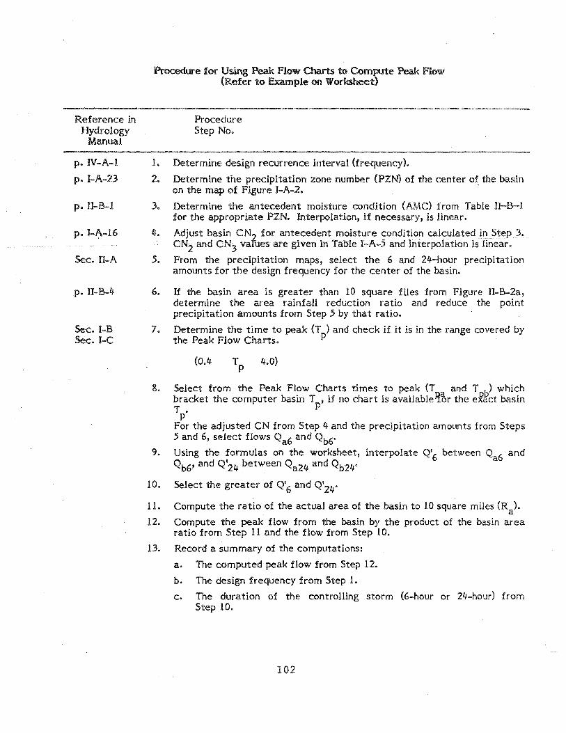
Reference in Hydrology
Manual
p. IV-A-l
p.I-A-23
p. II-B-l
p. I-~-16
Sec. II-A
p. II-B-4
Sec.I-B Sec. I-C
Procedw-e for Using Peak Flow Charts to Compute Peak Flow (Refer to Example 00 Worksheet)
1.
2.
3.
4.
5.
6.
7.
Procedure Step No.
Determine design recurrence interval (frequency).
Determine the precipitation zone number (PZN) of the center of the basin on the map of Figure I-A-2.
Determine the antecedent moisture condition (AMC) from Table U-B-l for the appropriate PZN. Interpolation, if necessary, is linear.
Adjust basin CN2 for antecedent moisture condition calculated in Step 3. CN2 and CN3 vafues are given in Table I-A-.5 and interpolation is linear.
From the precipitation maps, select the 6 and 24-hour precipitation amounts for the design frequency for the center of the basin.
If the basin area is greater than 10 square files from Figure II-B-2a, determine the area rainfall reduction ratio and reduce the point precipitation amounts from Step .5 by that ratio.
Determine the time to peak (T ) and check if it is in the range covered by the Peak Flow Charts. p
(0.4 Tp 4.0)
8. Select from the Peak Flow Charts times to peak (T and T b) which bracket the computer basin T , if no chart is available%r the e:Fact basin T • p
p For the adjusted CN from Step 4 and the precipitation amounts from Steps .5 and 6, select flows Qa6 and Qb6 0
9. Using the formulas on the worksheet, interpolate Q'6 between Qa6 and Qb6' and Q'24 between Qa24 and Qb24°
10. Select the greater of Q'6 and Q'24"
11. Compute the ratio of the actual area of the basin to 10 square miles (Ra).
12. Compute the peak flow from the basin by the product of the basin area ratio from Step 11 and the flow from Step 10.
13. Record a summary of the computations:
a. The computed peak flow from Step 12.
b. The design frequency from Step 1.
c. The duration of the controlling storm (6-hour or 24-hour) from Step 100
102
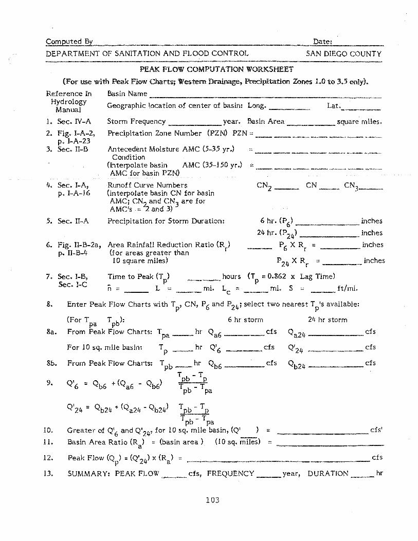
DEPARTMENT OF SANITATION AND FLOOD CONTROL SAN DIEGO COUNTY
PEAK FLOW COM PUT A nON WORKSHEET
(For use with Peak Flow Charts; Western Drainage, Precipitation Zones 1.0 to 35 only).
Reference In Hydrology
Manual
Basin Name ---------------------------------------------------------Geographic I.ocation of center of basin: Long. ___ _
1. Sec. IV-A Storm Frequency year. Basin Area square miles.
2. Fig. I-A-2, p. I-A-23
Precipitation Zone Number (PZN) PZN:: _______ _
3. Sec. II-B Antecedent Moisture AMC (5-35 yr.) = ___________ _ Condition
(Interpolate basin AMC 0.5-150 yr.) = ____________ _ AMC for basin PZN)
4. Sec. I-A, p. I-A-16
Runoff Curve Numbers (interpolate basin CN for basin AMC; CN2 and CN3 are for AMC's = -Z and 3)
CN __ CN3 __
.5. Sec. II-A Precipitation for Storm Duration: 6 hr. (P6
) inches
24 hr. (P24
) inches
6. Fig. II-B-2a, Area Rainfall Reduction Ratio (R ) p. II-B-4 (for areas greater than r
P6 X Rr :: inches
10 square miles) P24 X Rr :: inches
7. Sec. I-B, Sec. I-C
Time to Peak (T p) ---n = L ::: ___ mi.
hours (Tp :: 0.862 x Lag Time)
Lc :: ___ mi. S = ft/mi.
8.
8a.
8b.
9.
10.
11.
12.
13.
Enter Peak Flow Charts with T p' CN, P6 and P24; select two nearest Tp's available:
(For T pa T pb): 6 hr storm 24 hr storm
From Peak Flow Charts: T hr Q cfs Q _______ cis pa- a6 a24
For 10 sq. mile basin: T hr Q'6 cfs Q'24 p- cis ------From Peak Flow Charts: T hr Qb6 cis Qb24 pb- cis ------
T b - T Q'6 :: Qb6 + (Qa6 - Qb6) E E
T b - T P pa
Q'24::: Qb24 + (Qa24 - Qb24) T Eb - T E
T b - T P pa Greater of Q'6 and Q'24' for 10 sq. mile basin, (Q' ):: cfs' -------------------Basin Area Ratio (Ra) :: (basin area) (10 sq. miles) ::: ____________ _
Peak Flow (Qp) :: (Q'24) x (Ra) :::: cfs ---------------------------------------SUMMARY: PEAK FLOW cis, FREQUENCY ~ year, DURATION __ hr
103

DEPARTMENT OF SANIT A nON AND FLOOD CONTROL SAN DIEGO COUNTY
EXAMPLE 2: Proctor Valley above Upper Otay Reservoir
This example problem further lUustrates use of the Peak Flow Charts using
parameters previously computed. The procedures are the same as desribed in
Example 1. Since this basin is greater than 10 square miles in area, special
attention should be paid to Steps 6, 11, and 12 of the worksheet which involve
adjustments for areas other than 10 square miles.
104
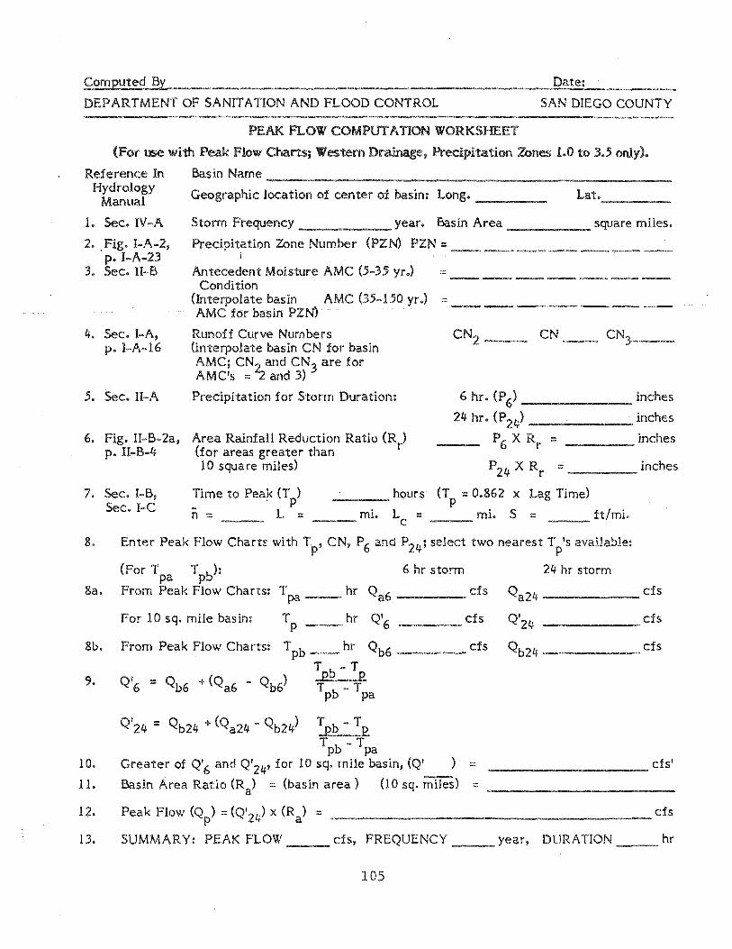
computed By Date:
DEPARTMENT OF SANITATION AND FLOOD CONTROL SAN DIEGO COUNTY
PEAK FLOW COM PUT A nON WORKSHEET
(For use with Peak Flow Charts; Western Drainage, Precipitation Zones 1.0 to 3.5 omy).
Basin Name Reference In Hydrology
Manual -----------~--------------------------------------------
Geographic location of center of basin: Long. ___ _
1. Sec. IV-A
2 •. Fig. I-A-2, p.I-A-23
Storm Frequency ______ year. Basin Area _____ square miles.
Precipitation Zone Number (PZN) PZN::: ___________ _ i
3. Sec. II-B Antecedent Moisture AMC (5-35 yr.) ::: ______________ _ Condition
(Interpolate basin AMC (35-150 yr.) ::: AMC for basin PZN) -------.-.- =--- ------- _ ... _. -
4. Sec. I-A, p. I-A-16
5. Sec. II-A
Runoff Curve Numbers (interpolate basin CN for basIn AMC; CN2.. and CN) are for AMC's :::""2 and 3)
Precipitation for Storm Duration:
CN __ CN3 __ _
6 hr. (P 6) _______ inches
24 hr. (P24) inches
6. Fig. II-B-2a, Area Rainfall Reduction Ratio (R ) p. II-B-4 (for areas greater than r
P 6 X Rr ::: inches
10 square miles) P 24 X Rr ::: ____ inches
7. Sec. I-B, Sec. I-C
Time to Peak (T ) . p n ::: L =
hours (T ::: 0.862 x Lag Time) --- p
___ mi. Lc = mi. S = ft/mi.
S. Enter Peak Flow Charts with T p' CN, P6 and P24 i select two nearest T pIS available:
(For T pa Tpbh 6 hr storm 24 hr storm
8a. From Peak Flow Charts: Tpa hr Qa6 cfs Qa2 4-
For 10 sq. mile basin: Tp hr Q'6 cfs Q'24
Sbe From Peak Flow Charts: T pb-- hr Qb6 cis Qb24 T b - T
9. Q'6 ::: Qb6 + (Qa6 - Qb6) E E T b - T P pa
Q'24 :::: Qb24 + (Qa24 - Qb24) T b - T P E
T b - T P pa 10. Greater of Q'6 and Q'24' for 10 sq. mile basin, <Q' ) ::::
11. Basin Area Ratio (Ra) = (basin area) (l0 sq. miles) :::
12. Peak Flow (Qp) :: (Q'24) x (Ra) ::::
13. SUMMARY: PEAK FLOW cis, FREQUENCY year, DURATION
105
cfs
cis
cfs
cis'
cis
hr

RUNOFF CURVE NUMBERS FOR HYDROLOGIC SOIL-COVER COMPLEXES (CN)
TABLE I-A-l
AMC2
Ia ::: 0.2S
Hydrologic Cover Soil Groups
Treatment Hydrologic
Land Use iOr Practice 3 Condition '+ A B C D
Water Surfaces (During floods) 97 98 99 99
Urban
Commercial-industrial 89 90 91 92
High density residential 75 82 88 90
Medium density residential 73 80 86 88
Low density residential 70 78 84 87
Baren 78 86 91 93
Fallow Straight row 76 85 90 90
Vineyards (see accompanying land-use description
Disked 76 85 90 92
Annual grass or Poor 65 78 85 89 legume cover
Fair 50 69 79 84
Good 38 61 74 80
5 Roads (hard surface) 74 84 90 92
(dirt) 72 82 87 89
Row crops Straight row Poor 72 81 88 91
Good 67 78 8.5 89
Contoured Poor 70 79 84 88
Good 65 7.5 82 86
Narrowleaf chaparral Poor 71 82 88 91
Fair 55 72 81 86
106

RUNOFF CURVE NUMBERS (CN)
AMC2
Hydrologic Cover Soil GrouEs
Treatment Hydrologic
Land Use or Practice .3 Condition 4 A B C D
Perennial grass Poor 67 79 86 89
Fair .50 69 79 84
Good .38 61 74 80
Annual grass Poor 67 78 86 89
Fair 50 69 79 84
Good 38 61 74 80
Close-seeded Straight row Poor 66 77 85 89 legumes or Good 58 72 81 85 rotated pasture
Contoured Poor 64 75 8.3 85
Good 55 69 78 83
Small grain Straight row Poor 65 76 84 88
Good 63 75 83 87
Contoured Poor 63 74 82 85
Good 61 73 81 84
Meadow. Poor 63 77 85 88
Fair 51 70 80 84
Good .30 58 72 78
Open brush Poor 62 76 84 88
Fair 1+6 66 77 83
Good 41 63 75 81
Farmsteads 59 71+ 82 86
Irrigated pasture Poor 58 74 83 87
Fair 44 65 77 82
Good 33 .58 72 79
107
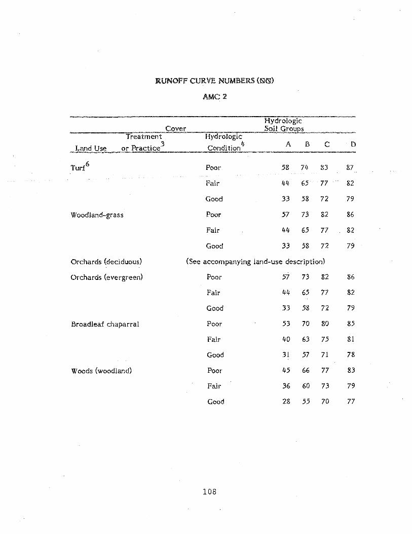
Turf 6
Woodland-grass
RUNOFF CURVE NUMBERS (!S!~)
AMC2
Cover Soil GrouEs Treatment Hydrologic
A B
Poor .58 74-
Fair 44- 65
Good 33 58
Poor .57 73
Fair 44 65
Good 33 .58
C
83
77
72
82
77
72
Orchards (deciduous) (See accompanying land-use description)
Orchards (evergreen) Poor .57 73 82
Fair 44 65 77
Good 33 .58 72
Broadleaf chaparral Poor .53 70 80
Fair 40 63 75
Good 31 57 71
Woods (woodland) Poor 4.5 66 77
Fair 36 60 73
Good 28 55 70
108
D
87
82
79
86
82
79
86
82
79
85
81
78
83
79
77

Table I-A-5 Curve Numbers (CN) and Constants for the Case I ::: 0.2 S a
1 2 :3 ~ .5 1 2 .3 4 5
CN CN for S Curve* CN CN for S Curve'*" for conditions Values* starts for conditions Values* starts con- I III where con- I III where dition p::: dition p:::: II II
(inches) (inches) (inches) {inches} i
100 100 100 0 0 60 40 78 6.67 1.33 99 97 100 .101 .02 59 39 77 9.95 1.39 98 94- 99 .204 .04- 58 38 76 7.24 1.45 97 91 99 .309 .06 57 37 75 7.54 1. 51 96 89 99 .417 .08 57 36 75 7.86 1.57 95 87 98 .526 .11 55 35 74 8.88 1.64 94 85 98 .638 .13 54 34 73 8.52 1.70 93 83 98 .753 .15 53 33 72 8.87 1.77 92 81 97 .870 .17 52 32 71 . 9.23 1.85 91 80 97 .989 .20 51 31 70 9.61 1.92 90 78 96 1.11 .22 50 31 70 10.0 2.00 89 76 96 1.24 .25 49 30 69 10.4 2.08 88 75 95 1.36 .27 48 29 68 10.8 2.16 87 73 95 1.49 .30 47 28 67 11.3 2.26 86 72 94 1.36 .33 46 27 66 11.7 2.34 85 70 94 1.76 .35 45 26 65 12.2 2.44 84 68 93 1.90 .38 44 25 64 12.7 2.54 83 67 93 2.05 .41 43 25 63 13.2 2.64 82 66 92 2.20 .44 42 24 62 13.8 2.76 81 64 92 2.34 .47 41 23 61 14.4 2.88 80 63 92 2.50 .50 40 22 60 15.0 3.00 79 62 91 2.66 .53 39 21 59 15.6 3.12 78 60 90 2.82 .56 38 21 58 16.3 3.26 77 59 89 2.99 .60 37 20 57 17.0 3.40 76 58 89 3.16 .63 36 19 56 17.8 3.56 75 57 88 3.33 .67 35 18 55 18.6 3.72 74 55 88 3.51 .70 34 18 54 19.4 3.88 73 54 87 3.70 .74 33 17 53 20.3 4.06 72 53 86 3.89 .78 32 16 52 21.2 4.24 71 52 86 4.09 .82 31 16 51 22.2 4.44 70 51 85 4.28 .86 30 15 50 23.3 4.66 69 50 84 4.49 .90 68 48 84 4.70 .90 25 12 43 30.0 6.00 67 47 83 4.92 .98 20 9 37 40.0 8.00 66 46 82 5.15 1.03 15 6 30 56.7 11.34 65 45 82 5.38 1.08 10 4 22 90.0 18.00 64 44 81 5.62 1.12 5 2 13 190.0 38.00 63 43 80 5.87 1.17 0 0 0 infinity infinity 62 42 79 6.13 1.23 61 41 78 6.39 1.28
*For CN in Column 1.
109

e ..,:-___ -L ,. ; · , I • i I
, ,
. 1 •
I· I ! .'
~ ·1" ~-~7:j:~' ~Wd~~~
I
°0 .. . =
110
" ... ... '", ... .... ..

I-' I-' I-'
JllTY Of" SAN 0 YEGG DEPI\RTMEUT OF SI\NHATIOH & fLOOD CONTI10l lOO-YEAR 6-HOUR
1
' PRECIPITATIOk'j '-20../ ISOPLUVIAlS OF lOO .. YEAR 6-uoun
rnECIPIT{\TIOrJ IN 45' _I \I':I~~:;::;";";
3)·'
, 1 .... -I
15' I I ~i F I •
. (-
I "58 .1 • __ II' infO llii I.Ii I
_____ •. _' _ ._ .. _ .. e __ • ...
H ,..... I
~ -.....!
Pre,,_ f·cI by
u.s. DEPARTMENlr OF COMMERCE NATIONAL OCt::ANI C AN 0 ATi::>SPII"IIIC I\D~I'NI5TRA TION
SPECiAl. STUDIES DRANCII. or-nct! 0 f IIi OROLOGY, NATION III.. WrcIlTII~R SIl:RVlCI!
30' I' _~ I UlP 115 1 30· IS- nt liS I 30' 15 1 116°

I-' I-' N
COUNTY Of' SAn DIEGO . DEPARTMENT Of SANITATION' flOO!) CONTROL
'.S I • '1,. ... -
30' ' ..
J 5 i r
.331b
,-1-
i,S s ,....11-----
r .<"of·db,
u.s. DEPARTMENlr OF CO~MERCE
100-YEI\ 11 24-1,1 oI/ rI rllECIPIT 1\ TI o~j r20JISOPlUVIAlS or- 100 24-1I0UR
PRECIPfTATIOr.J 1f·1 ~-EflTIfS OF
. lfAT!OI'lAI. OC!::I\:\IC /11'10 /I' '!Osa'''''Nfc A,lW";1STIlATION
"'COA~ 'Tu"," u.,.cn.)":."," "' ~r""'OGV' "'.","" "'AT"" 'i_R_Vl_C_E ____ + _______ l-____________________________ _
~ .... I )..
• to.:
I III" 11!i I )0' l'ii Ill" JO' I~ I I 16"
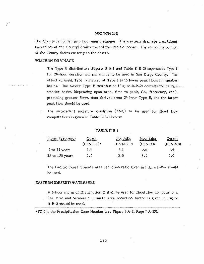
SECTiON fi..B
The County is divided into two main drainages. The westerly drainage area (about
two-thirds of the County) drains toward the Pacific Ocean. The remaining portion
of the County drains easterly to the desert.
WESTERN DRAINAGE
The Type Bi distribution (Figure II-B-l and Table II-B-2) supersedes Type 1
for 24-hour duration storms and is to be used in San Diego County. The
effect of using Type B instead of Type 1 is to lower peak flows for smaller
basins. The 6-hour Type B distribution (Figure II-B-2) controls for certain
smaller basins (depending upon area, time to peak, CN, frequency, etc.),
producing greater flows than derived from 24-hour Type B, and the larger
peak flow should be used.
The aritecedent moisture condition (AMC) to be used for flood flow
computations is given in Table II-B-l below:
TABLE ll-B-l
Storm Frequency Coast Foothills Mountains Desert --(PZN=l.O)* (PZN:::2.0) (PZN::3.0 (PZN=4.0)
5 to 35 years 1.5 2.5 2.0 1.5
35 to 150 years 2.0 3.0 3.0 2.0
The Pacific Coast Climate area reduction ratio given in Figure II-B-2 should
be used.
EASTERN (DESERT) VI A TERSHED
A 6-hour storm of Distribution C shall be used for flood flow computations.
The Arid and Semi-arid Climate area reduction factor is given in Figure
U-B-2 should be used.
*PZN is the Precipitation Zone Number (see Figure I-A-2, Page I-A-23).
113

I,.
FIGURE r1-6-2 .
HYDROLOGY: CRITERIA FOR DESIGN STORMS
1.0
().510
::rs:-. '1 'I '1 1 I r"'-- .. '" .-I r ~Ir PAi :F/C C~.<lSrAt ClIAfAre:~*
I 1 , t 111 r--... , I 1 I , I I --i I I I I ~~~ I'
! , I : I I , 4 NOS""" I : I I ~A,f ~ • 14~/!) ....... ; I! ! ct.;;", , I ,1 i I 4.,.c r:-:s.. , I I 1 ; I I I , I , I , , , .. ,
IS 2.0 2S ~o 35 40 45 50 60 70 00 90 100 DRAINAGe: AREA IN SQUARE MILES .
(0) RAINFALL RATIOS FOR DRAINAGE AREAS OF 10 TO 100 SQUARE MILES
'. /1 ce<n ~<n :;::>2:
:r: 00:7 ~gl.6 • :r: ."" <.0
ce a: ~ 0.6 ~
... t-ZZ :;::>:::>
0 0:e 0.5 ~~ .,J.,J .,J..J ,ct~ .. ~ ~ 0.4 -ct :'Il:
(;) i= C[ ce
(b) SIX HOUR DESIGN STORM DISTRIBUTION
REFEREt.;CE
U.S. Department of Agriculture' SQi I Conservation Service Engineering Division
114
V 'X:r: • <.0 /
/ V
~O cea: ~l: 1.5 ......
/ V
gJ~
~r ~l~ 1.3 ~~ <tIC: Il:Il:
0 f.i ce
- / 1.2
'j IV.
, , , ,
I.
12 .13 24 30 TIM£ IN HOURS
(c) RELATIVE INCREASE IN RAIN~ALL AMOUNT FOR STOR1A DURAT:ONS OVER SIX HOURS
COUNTY OF SAN DIEGO . DE?ARTHENT OF SANITATION At~D FLOOD 'CONTROL
II-B-4
~
-
0
36
..

20
19
1S
17
16
1S
14
13
12
11
10
9
8 &f)
La.. U
0 1 C> 0
... IJ,. 6 t.... 0 ::z: ::::> g;;;;
S
4
1
f-
f-
I--
! ;- - --.--
-.
!--- - , -'--
-
:LUU~11 OF SA~ DIEGO ·DE?AR1H-:::\'T OF .~.;n FLOOD CONTROL
--+
FLD\J FOR 10 SQ.. KILt:
6 HOUR STO~H - TYPE e DISTR!B •.
I 1 = ¥ 1
i :
!
--
._.-
- ">"'-,
--
--
: I
! ! i
~ :,.;..-:::: --:::::::... = :-= ._----_.::- ..
1 :2 :s 115 4 5 6
Al'i'-~ -1 0
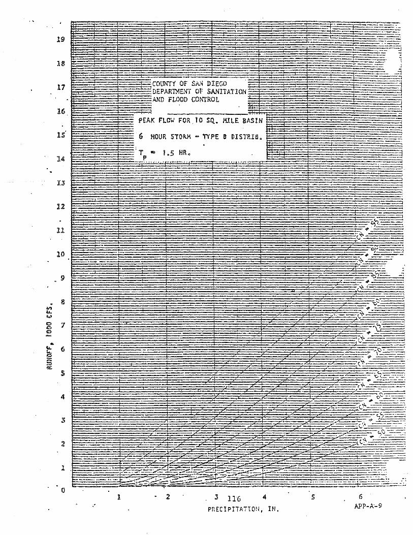
........
19 r--1'
18
17 ~
16
1S
14
12
11
1
~COUNTY OF S~~ DIEGO DEPARTMENT OF SANITATION AND fLOOD CONTROL
PEAK FlOV FOR 10 SQ. MllE BASIN
6 HOUR STO~ - TYPE e OISTRIB.
. -.'
:2 :3 116 PRECIPITATION, IN.
-"-Y ,
s
---
.: ---
=
-.,,\' _. ,\.;~-----i
-~~. --. -= ..... -=
;t~=~-':::
- .,. -""f¥ ~_-:-::-":::::::::::
o~----"'~=-"~
: t ...:.::-:-- . :. t.,'?--='-=~ .,
~<:.:-=--=--==-: 'r.,\J___ ...
:/'-~':\-
--== -.-
. .:.:....-:-:-:.~ - .--,.--- --
-.~==-- . ..:.:;.....::.; 6
A:PP-A-9

.. "" tA. C.J
0 CI 0
• • tA.
1.1. 0 :::: ::;::) 4111::
~-
19
18
CONUTY OF SAN 17 ~ DEPAR11-1E:---'T OF SANITATION ~ ~~D FLOOD CO~'TROL
16
lS
14
13
12
11 .
10
9
~-
8
7
6
S
4
3
- .1
-PEAK FI..O\.J FOR 10 SQ. .. MILE BASIN r--
24 HOUR STORM ... "NFlE B OISTR 13.
Tp lIB 1 HR .. ..... . . , .... . .
-).i:
; ----,.'-
-- -- -,...---..,..-
4 S
. . .
1 _--,..-,.
-
6 i
PRECIPITATI~~. IN. - - 117
I
-F
------$) • 10 11
;;.;::
-_ ......
--
.-
--
.-
---i
------' . -:::- ..
::--=--:::::::; ~
.- .-.--
.~
--i-- ~:.::::..:-::-:-:
12 .
APP-A-1S

21)
19
11
16
1S
14
12
li
10
. 9
• 8 VI L0.-U
e 7 c Q
s
2
1
o
~.t::::: .--
-.
COUNTY OF S~~ DIEGO DEPARTI-IE.'IT OF SA.I'llTATION ~\~ FLOOD CONTROL
PEAK FlOV FOR to SQ. ~!l£ BASIN
. 24 HOUR Si01Ui ... 1'Y PE 6 OISnna ..
; , i
i
-
,,~<
! i.Z;, . _4-.* ,------- ... -
'1--
. -~-/--"";"'-=-,·I-""~' ~_ r"-'-'..___"'-
,1'
,r
.. f
e_____'---:.:=::ts~~;:;=-~~ ~.
.1 4 s 6- 7
118 PRECUITATH'lN. IN.
.-
.--1-- -~
. '''1
.. -. .~::! _ ..... , - ---,' ,.~ .-:-:-~
...
---,----:::- ...... ) ._'-:-:.- ........ j "._--_.
9 • 10 11 12
APP-A-19

AREA (acres)
10
15
20
40
80
100
150
200
)~ jl
,\ WEIR" SPILLWAY, AND CHANNEL DIMENSIONS - DESILTING BASIN
Q ':'WIDTH HEIGHT H (Feet) (cfs) :~L;or b
: (f{:!et) WEIR SPILLWAY CHANNEL
'f . 1.5 1.5 1.0 . '·~i;6. 0
32 1:-0.: 4 0 2.0 1.5 1.2 :" . e
3.0 2.5 2.0 1.5 '.
\ . 8.5 1.5 1.5 1.0 46 5.5 2.0 1.5 1.2
'. 4.0 "
2.5 2.0 1.5
; 11.0 1.5 1.5 1.0 60 7.5 2.0 1.5 1.2
. 5.5 2.5 2.0 1.5
20.5 1.5 1.5 1.0 11.3 13.5 2.0 1.5 1.2
. 9.5 2.5 2.0 1.5
24.0 2.0 1.5 1.2 204 17.0 2.5 2.0 1.5
29.0 2.0 1.5 1.2 246 21.0 2.5 2.0 1.5
343 29.0 2.5 2.0 1.5
429 36.0 2.5 2.0 1.5
RUNOFF FOR 5-YEAR STORM FREQUENCY. FLOW IS THROUGHOUT.
----~------- - ----~---------- ----------
*For unusual shaped drainage areas 40 acres or larger, compare tabled Q with Q labeled hereon.
0\ rl rl
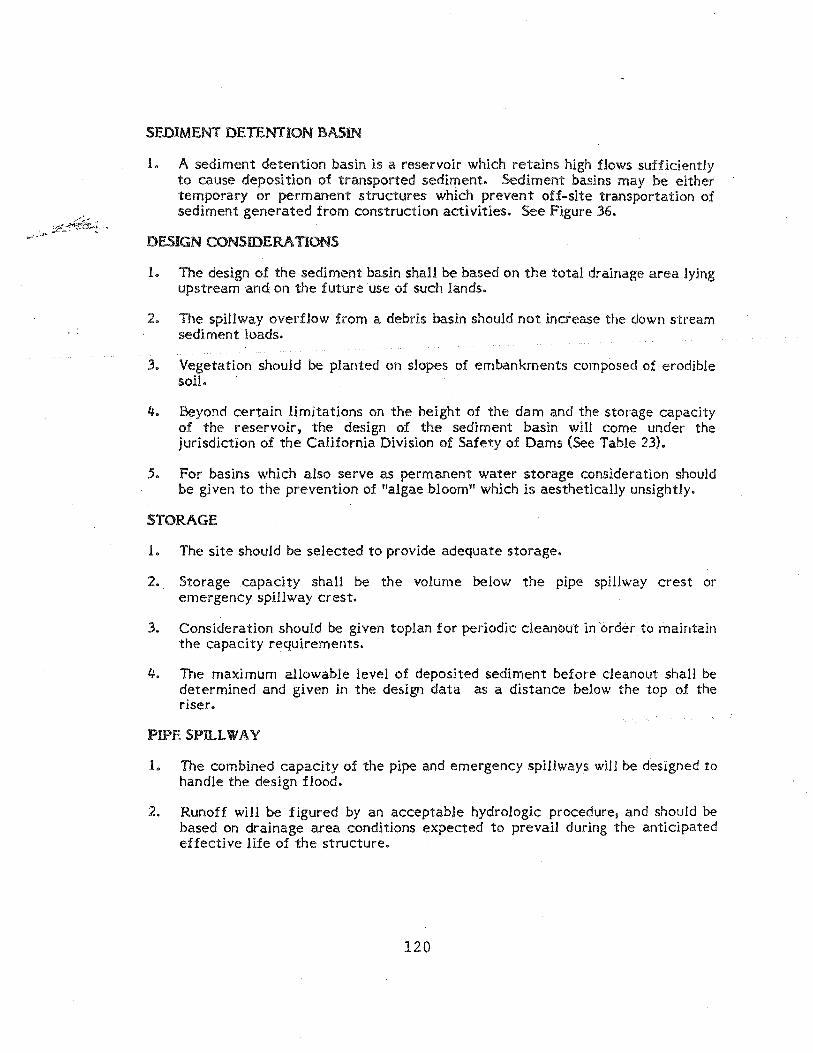
SEDIMENT DETENTION BASIN
1. A sediment detention basin is a reservoir which retains high flows sufficiently to cause deposition of transported sediment. Sediment basins may be either temporary or permanent structures which prevent off-site transportation of sediment generated from construction activities. See Figure 36.
DESIGN CONS IDE RA nONS
1. The design of the sediment basin shall be based on the total drainage area lying upstream and on the future use of such lands.
2. The spillway overflow from a debris basin should not increase the down stream sediment loads.
3. Vegetation should be planted on slopes of embankments composed of erodible soil.
4. Beyond certain limitations on the height of the dam and the storage capacity of the reservoir, the design of the sediment basin will come under the jurisdiction of the California Division of Safety of Dams (See Table 23).
5. For basins which also serve as permanent water storage consideration should be given to the prevention of tlalgae bloom" which is aesthetically unsightly.
STORAGE
1. The site should be selected to provide adequate storage.
2. Storage capacity shaH be the volume below the pipe spillway crest or emergency spillway crest.
3. Consideration should be given toplan for periodic cleanout in order to maintain the capacity requirements.
4. The maximum allowable level of deposited sediment before c1eanout shall be determined and given in the design data as a distance below the top of the riser.
PIPESPll..LWAY
1. The combined capacity of the pipe and emergency spillways will be designed to handle the design flood.
2. Runoff will be figured by an acceptable hydrologic procedure, and should be based on drainage area conditions expected to prevail during the anticipated effective life of the structure.
120

3. The pipe spillway will consist of a perforated vertIcal pipe or box-type riser joined to a horizontal pipe conduit (barrel) which will extend beyond the downstream toe of the embankment.
4. The horizontal pipe conduit (barrel) will be a minimum of twelve inches (12") in diameter.
5. The riser IS a minimum of thirty inches (30") in diameter and has a cross-sectional area of at least 1.5 times the cross-sectional area of horizontal pipe conduit.
;
6. The crest elevation of the riser shall be such that full flow will be generated before there is discharge through emergency spillway and at least one foot below crest of emergency spillway.
7. If no emergency spillway is provided. the crest elevation of riser must be at least three feet below crest of emergency spillway.
8. The upper halt to two-thirds of the riser shall be perforated with one and one-half to four inch (1-1/2 11
- 4") holes, 10 to 12 inches on center and staggered.
9. The antivortex device can increase volume of discharge by as much as !ifty percent (50%).
10. An approved antivortex device is a thin, vertical plate normal to the centerline ot the dam and firmly attached to the top of the riser. The plate dimensions are:
Height :::: diameter of barrel
Length :::: diameter of riser plus twelves inches (12")
11. The riser shall have a base attached with a watertight connection and shall have sufficient weight to prevent floatation of the riser. Three recommended methods are:
a. A square concrete base eighteen inches (18") thick with the riser embedded six inches (6") in the base. Each side of base will be diameter of standpipe plus twenty-four inches (24").
b. A one-quarter inch (1/4") minimum thickness steel plate weldea all around the base of the riser to form a watertlght connection. The plate shall be square with each side equal to two times the riser diameter. The plate shall have two feet of stone. gravel or tamped earth placed on it to prevent floatation.
c. Properly anchored guy wires may be substh uted for the anchor block.
121

12. The trash rack consisting of 114 bars, 6 inches on center shall be welded across the top of riser.
1.3. At least one seepage ring is required and each ring shall be rectangular with each side a minimum of barrel diameter plus 24 inches.
EMERGENCYSpaLWAY
1. The emergency spillway should be designed for 1 • .5 maximum design flow. Two recom mended designs are:
a. Discharge over top of dam or embankment. SpiHway must be lined wIth .3 inch thick gunite or 4. inch concrete reinforced with 6 X 6 - 10/10 wire mesh, extending to a minimum of .3 feet down the upstream face of embankment. Spillway will be minimum of 18 inches deep with 1-1/2:1 side slopes.
b. Earth spillways must be installed on undisturbed soil (not on fill) by grading. Side slopes will not be steeper than 2:1. Embankment and spillway channel must be protected by vegetation, rock riprap, etc. The maximum allowable velocity in exit channel shall be 6 feet per second.
FREEBOARD
1. Freeboard is the vertical distance between the elevation of the water surface in the pond when spillway is discharging at designed depth and the elevation of the top of the dam after all settlement has taken place.
2. Minimum freeboard shall be 1.0 foot for sediment basins where the maximum length of pond is less than 660 feet.
EMBANKMENT
1. The embankment shall have top widths based on the following:
Height of Dams
Under 10' 10' - 15' 15' - 20' 20' - 25'
2. Slide shall be no steeper than 2:1.
CONSTRUCTION
122
Top Width
8' 10' 12' 14'

SITE PREPARATION
1. The foundation area reservoir area shall be cleared of all trees, stumps, roots, brush, boulders, sod, and debris.
2. All topsoil containing excessive amounts of .organic matter shall be removed.
BORROW AREAS
1. All borrow arpas outside the pool shall be graded, seeded, and left in such a manner that they are well drained and protected from erosion.
EMBANKMENT
1. The embankment material shall be taken from borrow areas as stated en plans.
2. The material shall be free .of all scd, rcots, woody vegetation, large rock (exceeding 6 inches in diameter,) and other debris.
3. The embankment should be constructed te an elevation which provides for anticipated settlement to design elevation (allow 1096 for settlement).
4. The foundaticns fer embankment shall be scarified prior te placement .of fill.
5. Placement .of fill material shall be started at the lowest point of the foundaticn and shall be placed in 6 inch maximum lifts which are to be continuous over entire length .of fill and approximately horizontal.
6. The satisfactcry compaction is usually achieved when the entire surface of the fill is traversed by at least .one pass .of the load hauling equipment or threugh use of a reller.
PIPE SPll..L WAY
1. The barrel shall be placed .on a firm feundation te the lines and grades shown on the plans.
2. Backfill material shall be placed arcund the barrel in 4 inch layers and each layer shall be the roughly compacted with suitable hand-operated equipment to . at least 2 feet above the top of the pipe and seepage rings before heavy equipment is operated over it.
VEGETATIVE PROTECTION
1. A pretective cever shaH be established en all exposed surfaces .of the embankment, spillway, and borrow area to the extent practical.
123

PROTECTION OF SPILLWAY DISCHARGE AREA
1. All areas subject to discharges from pipe spillway and emergency spillway must be protected with vegetation, rock, riprap, etc.
SEDIMENT CLEANOUT AND DISPOSAL
1. The sediment should be removed whenever the storage capacity has been reduced to unsafe, improperly functioning levels.
2. The sediment must be disposed of in such a manner that will prevent its return to the sediment basin or movement into downstream areas during subsequent runoff.
124

TABLE 23. DESIGN LIMITATIONS AND JURISDICTION OF DAMS IN CALIFORNIA.
Condi- DESIGN Jurisdiction by the tion HEIGHT STORAGE USE OF DAM California Division
(ft) . I
(acre-It) of Safety of Dams
1 <;.6 No limit Impound or divert No (sec. 6003) water.
2 No limit <=-15 Impound or divert No (sec. 600.3) - water.
3 ~5 No limit Underground per- No (sec. 6004) colation.
4 ~25 '2: 15 Impound or divert Yes (sec. 6002a) water.
5 No limit 2:50 Impound or divert Yes (sec. 6002b) water.
125

· ..
6
o
PROVISIOt~s OF DIVISION 3 OF THE CALIFORNIA WATER CODE AFFECTING JURISDICTION OVER DAMS AND RESERVOIRS
15 "'Acre-Feet
RESERVOIR CAPAqTY .
°Metric \,tNt" not .. pec-1Ued in the Water Code elre!
1.83 ",,,tre." 6 feet 18.50 "'.e;olllrea " 1S AC,.,..r., .. t '7.62 ", .. treo " 25 feet 61.68 m ...... Ii'...,. '" 50 ."r .... r~et
126
50

ENEIroY DISSIPATOR ANTI-SEEP
l/ I.:. '~2':' ====df=:::==~~---I J\IPfUP 6" ~IS.
MSClW{CE TO PI. VED lIft!!:. 011 APPROVED DRAlt;ACE COURSE III 'A VE.D CI!AN1'E
--
OJ! EACH PIKE
rlfij\lre 36. S~hemolic: Design of Sediment Detention B<nil'ls. [20] [50)
127
ANTi-VORTEX PLATE
GROUND
GRAVEL CONE
SECnt:m A-A OUNlTE OR CONCR-~ AT THE CVEfU'LOIi IS 'ro £X'l'tll'D 3' 111111. OOW EACH PACE 01' THE OlD!.
,30" PIAl'tEn:l\ S'l.'A1IDPll'Z
Ii& nRFORA'.!'IONB 12" ole IrXAWl:!U':ll
II PROPERLY ANCHORED GUY WIRES t.tAY BE SUBSTITUTED FOR THE ANCHOR BI..OCK.
2) SEE SECTION 52 .15 FOR RECOMMENED WIDTH OF EMBANKMENT.
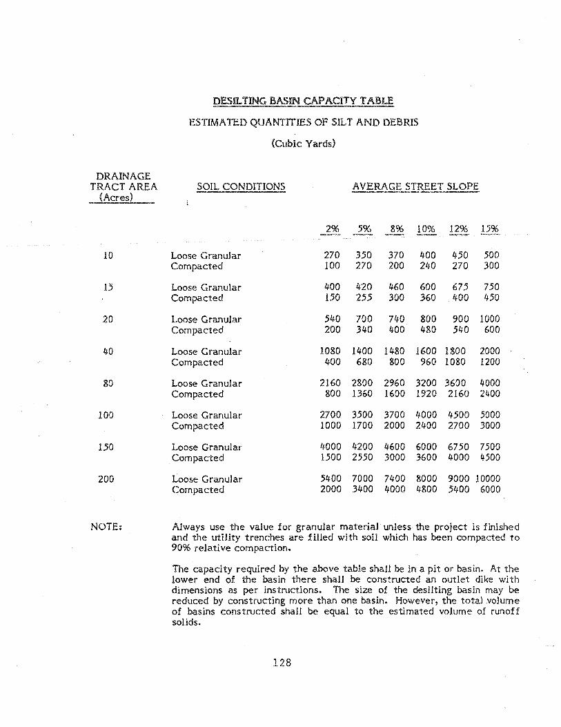
DESIL TING BASIN CAPACITY TABLE
ESTIMA TED QUANTITIES OF SILT AND DEBRIS
(Cubic Yards)
DRAINAGE TRACT AREA SOIL CONDITIONS AVERAGE STREET SLOPE
(Acres)
5% 8% 10% 12% 15%
10 Loose Granular 270 350 370 400 450 500 Compacted 100 270 200 240 270 300
15 Loose Granular 400 420 460 600 675 750 Compacted 150 255 300 360 400 450
20 Loose Granular 540 700 740 800 900 1000 Compacted 200 340 400 480 540 600
40 Loose Granular 1080 1400 1480 1600 1800 2000 Compacted 400 680 800 960 1080 1200
80 Loose Granular 2160 2800 2960 3200 3600 4000 Compacted 800 1360 1600 1920 2160 2400
100 Loose Granular 2700 3500 3700 4000 4500 5000 Compacted 1000 1700 2000 2400 2700 3000
150 Loose Granular 4000 4200 4600 6000 6750 7500 Compacted 1500 2550 3000 3600 4000 4500
200 Loose Granular 5400 7000 7400 8000 9000 10000 Compacted 2000 3400 4000 4800 5400 6000
NOTE: Always use the value for granular material unless the project is finished and the utility trenches are filled with soil which has been compacted to 90% relative compaction.
The capacity required by the above table shall be in a pit or basin. At the lower end of the basin there shall be constructed an outlet dike with dimensions as per instructions. The size of the desilting basin may be reduced by constructing more than one basin. However, the total volume of basins constructed shall be equal to the estimated volume of runoff solids.
128

TYPICAL 'DESILTING BASIN . ~Smf'mproved _.-AI'
,- reef
,. I mifl
PAVED BERM DETAIL
~ O';'Ioollor Paved Berm -see detail ~I-I I
(;\
~
,.
ndpipNl - .""d '4 hr' i'" "!:fon lop of pip.,
~---------
1111., apron Of $Ir,,' #lJellolion and floplng stseper than $trul flrad~
POlled Inlel with Wingwolls .... 3"A.C 'or gunUI
~
S,. Figure G 1548 for desillill9 b{nln
,apacilll"quinui
.~~ .. .. . ~ () . Stondplpe -18 C.M.P. WI'" ..... ~ 2" perlolaiiollS@8"O,', o g, full Illngih above G. L. 4:.~ ___ ~ ~
~ .d <" 12"moll.
~ ::-R'-~'-' ____ --...II
,"Conc. (mitlJ
DETAil Of Sf.EP RING
NOT£:
Apron or channel pavld
to paved streef, ,'orm droin, or water
course . . Su Figure G 154A.
Willi tandem basillf, OpfOfl or ChOMlI1 sholl h' 20' minimum leng/h. USIII
,uloft wall of ,lid of spi/lOl(oy.
~~----~--~--------------~~-------- -q~ ~ -i E ,oo'}-+-__ "'-4./LL/LLLU'-{?~ V/..(' ./.,('L'( "'./,<.4 /./../..4 ,,('''/''U?'!::s:---_.-=:-
~~ J:J / FI2"min/iii:;77/27n)7771ic?.~
GL i' ,.' S 2"" " .. . "- --J, . • • I I ' lope ,. fflltl ': 18 CM.P. or 11111111'.
1) » » ••• , • " , • > , , > ,> > • > > > > > • > » > ) j •• » •• , > •• , .~ «:1t---~~~OII CW;~'· IF=!~I~ :U~i~II-:;:I~:~lIimJ 2% mill.
ON
• -,' K:'" •• SECTION A-A " mil\.
- BASIN OUTLET
Nol,; O,silli"' . buill on loIs odjacflll 60 311011 bll compf"ifll1nod with. Of gllliil,. Ih,,1913
I. ~ 3" A.C. or Gunilll l3p' .( chofln,/
z·u I
0'> N rl

f3AS1N CAPACITY TABLE ON CUBIC "tAROS)
~PRON OR PAVED CHANNE . . TO STORM CRAIN OR WATER COURSE
OBLIQUE VIEW
3111 GUNliE SPILLWAY 6,;6 -fOliO WIRE MESH
TRACT AREA
{ACRES
10
H5 20
40
800
850 200
WELD '#4 REBAR CAGE ~NDPI?£-18"C.S.P. WITH
AVERAGE SLOPES
2% 5% 80/0
270 350 370 s.-
4001 420 460
540 700 740 BOO 900110001
1080 1400 1480 150011800! 20001
2160 2S00 2~60132001360014COOI
270013500137001";000145001 50 CO! 4000 420oI4600isoools7:0!75001
. . ISIiIC.S.P. OR EQUIVALENT ALL J01NTS WATERTiGHT
W: WIDTH AS 0:' Tc.RMiNED 8"1" ENGINE::R TO SE SHOWN ON PLANS
. NOTES nOESILTATlON BASINS BUILT'ON LOTS
ADJACENT TO DWELLINGS SHALL::: COMPLETELY LJNED WITH ;:3<1 GUNITI
TO TOP OF STAN/PIPE Z"PERFORATIONS AT S"Oe. 2)WtTH TANDEf'1l BASINS CHANNEL FULL LENGTH A80VE G.L. SHALL 8E 20' MINlr~UM LENGTH.
1281 MAX. ~. MIN,. t USE CUTOFF WALL AT END OF rl t-- I SPJl..l..WA't'.· . \ I I, US MIN. I .
..".
:: 2% MIN. ftr
\:, " ,Air" ..
"N z, SEEP RING I :i .: '- ua"eS.P-OR EOUIVALENT......!
6: I' "'-A.C. OR GUNITE r- CUTOFF WALL . SECTION A-A
2'% MfN. I . I """'/",";//'0 / .u
. r---+---; !G«A.C. OR GUNITE CHANNEL OR RIP RAP PER STD. 0-40
REV. APPROvED DATE CITY OF CARLSBAD t:~ I'd.
CITY thC;'HtER
r---+-----~..............j DES1LTATION 8ASH\~ OUTLET ~---SU?Pt.EMENTAl D"""· ":
AND CAPACITY TABLE STANDARD NO. .::.- ...
130

..... (.oJ .....
What pH Values Mean* ACIDIC
(I..onr Numberll) NEUTRAL
! ll1lmon Rilling Julc4I Soda
Cle.n Sea RiIIlnfllill 'Water
Vlllilllr 0 1 . 2 3 4 5. 8 1 8 91 .10
I ~ Acid Preclpll.llon ~ I ; :
"Each number represenlslII tllnfold increASe Of deere8se In ~cldlly.
.' _ ..
ALKALINE (Hlgh8r Numberll)
t ...
AmiCI'I11 ... J
I 11 12 13 14
,'. ";' -, . ,"
.. ' '. '. ' ",t' . '-. ",:; ~ " . ~ * ~. " :' .
. . ' " .... .. . ' . , .
.... ; '. J

HIGHWAY DESIGN MANUAL 7-881.1 April 2. 1979
Glossary of Drainage Terms (7....sS1) The definitions in this Glossary are for use with this
Manual and the references cited. They are not necessarily definitions .as established by case or statutory law.
Accretion-Outward growth of bank or shore by sedimentation. Increase or extension of boundaries of land by action of natural forces.
Acre-Foot-A unit of measurement for volume of water. It is equal to the quantity of water required to cover one acre to a depth of one foot and is equal to 43,560 cubic feet or 325,851 gallons. The term is commonly used in measuring volumes of water used or stored. !
Aggradation-Upgrading of a stream bed by sedimentation. Modification of the earth's surface in the direction of uniformity of grade, or slope, by deposition as in a river bed.
Aggressive-Refers to the corrosive properties of soil and water.
Alluvium-Stream-borne materials deposited in and along a channel.
Apron-A lining of the bed of the channel upstream or downstream from a lined or restricted waterway. A floor or lining of concrete, timber, etc., to protect a surface from erosion such as the pavement below chutes, spillways, at the toes of dams, or along the toe of bank protection.
Aqueduct-(l) a major conduit. (2) The entire transmission main for a municipal water supply which may consist of a succession of canals. pipes, tunnels, etc. (3) Any conduit for water; especially one for a large quantity of flowing water. (4) A structure for conveying a canal over a river or hol-low. .
Aquifer-Water-bearing geologic f6rmations that permit the movement of ground water.
Artesian Waters-Percolating waters confined below impermeable formations with sufficient pressure to spring or well up to the surface.
Avulsion-(l) A forcible separation; also, a part tom off. (2) The sudden removal of land from the estate of one man to that of another, as by a sudden change in a river, the property thus separated continuing in the original owner. (A sudden shift in location of channel.)
Backwater-An unnaturally high stage in stream caused by obstruction or confinement of flow, as ,by a dam. a bridge, or a levee. Its measure is the excess of unnatural over natural stage, not the difference in stage upstream and downstream from its cause.
Bank-The lateral boundary of a stream confining water flow. The bank on the left side of a channel looking downstream is called the left bank, etc.
Bank Protection-Revetment-or other armor
132
protecting a bank of a stream from erosion-includ~' devices used to deflect the forces of erosion awa) from the bank.
Bedding-The foundation under a drainage structure.
Bedload-That solid material which is heavier than water and is transported by the flowing water along or close to the bed. May consist of silt, sand and Tocks.
Bulking-The increase in volume of flow due to air entrainment, debris, bedload, or sediment in suspension.
Camber-An upward adjustment of the profile of a drainage facility under a heavy loading (usually a high embankment) and poor soil conditions, so that as the drainage facility settles it approaches the design profile.
Capacity-The effective carrying ability of a drainage structure. Generally measured in cubic feet per second.
Capillarity-The attraction between water and soil particles which causes water to move in any direction through the soil mass regardless of gravitational forces.
Capillary Water-Water which clings to soil particles by capillary action. It is normally associated with fine sand, silt, or clay, but not normally with coarsf' sand and gravel.
Catch Basin-A drainage structure which collects water. May be either a structure where water enters from the side or through a grating.
Check Dam-A small dam generally placed in steep ditches for the purpose of reducing the velocity .in the ditch.
Cienega-A swamp formed by water rising to the surface at a fault.
Cleanout-An access opening to a roadway drainage system. Usually consists of a manhole shaft, a special chamber or an opening into a shallow culvert or drain.
Coefficient of Runoff-Percentage of gross rainfall which appears as runoff.
Concentrated Flow-Flowing water that has been accumulated into. a single fairly narrow stream.
Concentration-In addition to its general sense, means the unnatural collection or convergence of waters so as to discharge in a narrower width, and at greater depth 'or velOCity.
Conduit-Any pipe, arch, box or drain tile through which water is conveyed.
Control-A natural constriction of the channel, a long reach of the channel, a stretch of rapids, or an artificial structure downstream from a gaging stanol!
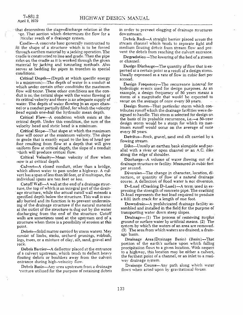
7-881.2 April 2, 1979
HIGHWAY DESIG~ 'MAI\UAL
that determines the stage-discharge relation at the "'ge. That section which determines the flow for a
tticular reach of a drainage system. Cradle-A concrete base generally constructed to
fit the shape of a structure which is to be forced through earthen material by ajacking operation. ~he cradle is constructed to line and grade. Then the pIpe rides on the cradle as it is worked through the given material bv jacking and tunneling methods. Also serves as bedding for pipes in trenches in special conditions.
Critical Deptn-(Depth at which specific energy is a minimum)-The depth of water in a conduit at which under certain other conditidns the maximum flow will Occur. These other conditions are the conduit is on the critical slope with the water flowing at its critical velocity and there is an adequate supply of water. The depth of water flowing !n an open channel or a conduit partially filled, for which the velocity head equals one-half the hydraulic mean depth.
Critical Flow-A condition which exists at the critical depth. Under this condition, the sum of the velocity head and static head is a minimum.
Critical Slope-That slope at which the maximum flow will occur at the minimum velocity. The slope or grade that is exactly equal to the loss of h:ad l?er foot resulting from flow at a depth that will give uniform flow at critical depth; the slope of a conduit "'hich will produce critical flow.
Critical Velocity-Mean velocity of flow when rlow is at critical depth.
Culvert-A closed conduit, other than a bridge, which allows water to pass under a highway. A culvert has a span ofless than 20 feet, or ifmultispan, the individual spans are ten feet or less.
Cutoff WalJ-A wall at the end of a drainage structure, the top of which is an integral part of the drainage structure, while the actual cutoff wall extends a specified depth below the structure. This wall is u~ually buried and its function is to prevent underml.ning of the drainage structure if the natural matenal at the outlet of the structure is dug out by the water discharging from the end of the structure. Cutoff walls are sometimes used at the upstream end of a structure when there is a possibility of erosion at this point.
Debris-Solid matter carried by storm waters. May consist of limbs. sticks, orchard prunings, rubbish, logs, trees, or a mixture of clay, silt. sand, gravel and rock.
Debris Barrier-A deflector placed at the entrance of a culvert upstream, which tends to deflect heavy floating debris or boulders away from the culvert entrance during high-velocity flow.
Debris Basin-Any area upstream from a drainage 'ructure utilized for the purpose of retaining debris
in order to prevent clogging of drainage structures do\vnstream.
Debris Rack--A straight barrier placed across the stream channel which tends to separate light and medium floating debris from stream flo\\,' and prevent the debris from reaching the culvert entrance.
Degradation-The lowering of the bed of a stream or channel.
Design Discharge-The quantity of flow that is expected at a certain point as a result of a design storm. Usually expressed as a rate of flow in cubic feet per second.
Design Frequency-The recurrence interval for hydrologic events used for design purposes. As an example, a design frequency of 50 years means a storm of a magnitude that would be expected to recur on the average of once every 50 years.
Design Storm--That particular storm which contributes runoff.\\'hich the drainage facilities were designed to handle. This storm is selected for design on the basis of its probable recurrence, Le.-a 50-year design storm wouL<l be a stOrtn for which its maximum runoff would occur on the average of once every 50 years.
Detritus-Rock, gravel, sand and silt carried by a flowing stream.
Dike-Usually an earthen bank alongside and parallel with a river or open channel or an A.C. dike along the edge of shoulder.
Discharge-A volume of water flowing out of a drainage structure or facility. Measured in cubic feet per second.
Diversion-The change in character, location, direction or quantity of flow of a natural drainage course.' A deflection of flood water is not diversion.
D-Load (Cracking D-Load)-A term used in expressing the strength of concrete pipe. The cracking D-load represents the test load required to produce a 0.01 inch crack for a length of one foot.
Downdrain-A prefabricated drainage facility assembled and installed in the field for the purpose of transporting water down steep slopes. .
Drainage-(l) The process of removing surplus ground or surface water by artificial means. (2) The system by which the waters of an area ~re remov~d. (3) The area from which waters are dramed; a dramage basin.
Drainage Area (Drainage Basin) (Basin ) -That portion of the earth's s~rface up?n wh.ich falling precipitation flows to a gIven locahon. WIth respect to a highway, this location may be ei~her a culvert, the furthest point of a channel, or an mlet to a roadway drainage system.
Drainage Course-Any path along which water flows when acted upon by gravitational forces.
133
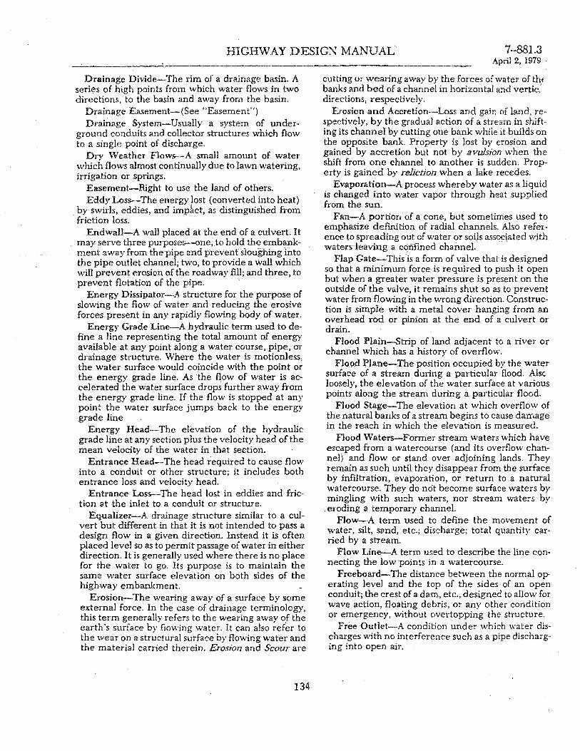
HIGHWAY DESIGN MANUAL 7-881.3
Drainage Divide-The rim of a drainage basin. A series of high points from which water flows in two directions, to the basin and away from the basin.
Drainage Easement-(See "Easement") Drainage System-Usually a system of under
ground conduits and collector structures which flow to a single point of discharge.
Dry Weather Flows-A small amount of water which flows almost continually due to lawn watering, irrigation or springs.
Easement-Right to use the land of others. Eddy Loss-The energy Jost (converted into heat)
by swirls, eddies, and imp~ct, as distinguished from friction loss.
EndwaH-A wall placed at the end of a culvert. It may serve three purposes--one,.to hold the embankment away from the pipe and prevent sioughing into the pipe outlet channel; two, to provide a wall which will prevent erosion of the roadway fxll; and three, to prevent flotation of the pipe.
Energy Dissipator-A structure for the purpose of slOWing the flow of water and redUCing the erosive forces present in any rapidly flowing body of water.
Energy Grade Line-A hydraulic term used to defxne a line representing the total amount of energy available at any point along a water course, pipe, or drainage structure. Where the water is motionless, the water surface would coincide with the point or the energy grade line. As the flow of water is accelerated the water surface drops further away from the energy grade line. If the flow is stopped at any point the water surface jumps back to the energy grade line.
Energy Head-The elevation of the hydraulic grade line at any section plus the velocity head of the mean velocity of the water in that section.
Entrance Head-The head required to cause flow into a conduit or other structure; it includes both entrance loss and velocity head.
Entrance Loss-The head lost in eddies and friction at the inlet to a conduit or structure.
Equalizer-A drainage structure similar to a culvert but different in that it is not intended to pass a design flow in a given direction. Instead it is often placed level so as to permit passage of water in either direction. It is generally used where there is no place for the water to go. Its purpose is to maintain the same water surface elevation on both sides of the highway embankment.
Erosion-The wearing away of a surface by some ex~ernal force. In the case of drainage terminology, thiS term generally refers to the wearing away of the earth '5 surface by flOWing water. It can also refer to the wear on a structural surface by flOWing water aI)d the material carried therein. Erosion and Scour are
134
April 2, 1979
cutting or wearing away by the forces of water of thf banks and bed of a channel in horizontal and vertic,' directions, respectively.
Erosion and Accretion-Loss and gain of land, respectively, by the gradual action of a stream in shifting its channel by cutting one bank while it builds on the opposite barue Property is lost by erosion and gained by accretion but not by avulsion when the shift from one channel to another is sudden. Property is gained by reliction when a lake recedes.
Evaporation-A process whereby water as a liquid is changed into water vapor through heat supplied from the sun.
Fan-A portion' of a cone, but sometimes used to emphasize defxnition of radial channels. Also reference to spreading out of water or soils associated with waters leaving a c~nfmed channel.
Flap Gate-This is a form of valve that is designed so that a minimum force is required to push it open but when a greater water pressure is present on the outside of the valve, it remains shut so as to prevent water from flowing in the wrong direction. Construction is simple with a metal cover hanging from an overhead rod or pinion at the end of a culvert or drain.
Flood Plain-Strip of land adjacent to a river or channel which has a history of overflow.
Flo.od Plane-The position occupied by the water surface of a stream during a particular flood. Alsc loosely, the elevation of the water surface at various points along the stream during a particular flood.
Flood Stage-The elevation at which overflow of the natural banks of a stream begins to cause damage in the reach in which the elevation is measured.
Flood Waters-Former stream waters which have escaped from a waterCOHTse (and its overflow channel) and flow or stand over adjoining lands. They remain as such until they disappear from the surface by infxltration, evaporation, or return to a natural watercourse. They do not become surface waters by mingling with such waters, nor stream waters by
. eroding a temporary channel. Flow-A term used to defxne the movement of
water, silt, sand, etc.; discharge; total quantity car-ried by a stream. .
Flow Line-A term used to describe the line connecting the low points in a watercourse.
Freeboard-The distance between the normal operating level and the top of the sides of an open conduit; the crest of a dam, etc., designed to allow for wave action, floating debris, or any other condition or emergency, without overtopping the structure.
Free Outlet-A condition under which water discharges with no interference such as a pipe discharging into open air.

7-881.4 April 2, 1979
HIGHWAY DESIGN ·MANUAL
Free Water-Water which can move through the . "il by force of gravity.
French Drain-A trench loosely backfilled with stones, the largest stones being placed in the bottom with the size of stones decreasing towards the top. The interstices between the stones serve as a passageway for water.
. Grade to Drain-A construction note often inserted on a plan for the purpose of directing the Contractor to slope a certain area in a specific direction, so that the storm waters will flow to a deSignated location.
Gradient (Slope) -The rate of a~cent or descentexpressed as a percent or as a decunal as determined by the ratio of the change in elevation to the length. . Ground 'Water-That water which is present under the earth's surface. Ground water is that situated below the surface of the land, irrespective of its source and transient status. Subterranean streams are flows of ground waters parallel to and adjOining stream waters, and usually determined to be integral parts of the visible streams.
Head-When used as a hydraulic term, this represents an available force equivalent to a certain depth of water. This is the motivating force in effecting the movement of water. The height of water above any point or plane of reference. Used also in various compound expressions, such as energy head, entrance "ead, friction head, static head, pressure head, lost . ead, etc.
Hydraulic Gradient-A line which represents the relative force available due to the potential energy available. This is a combination of energy due to the height of the water and the internal pressure. In any open channel, this line corresponds to the water surface. In a closed conduit, if several openings were placed along the top of the pipe and open tubes inserted, a line connecting the water surface in each of these tubes would represent the hydraulic grade line.
Hydraulic Jump (or Jump)-Transition of flow from the rapid to the tranquil state. A varied flow phenomenon producing a rise in elevation of water surface. A sudden transition from supercritical flow to the complementary subcritical flow, conserving momentum and dissipating energy.
Hydraulic Mean Depth-The area of the flow cross section divided by the water surface width.
Hvdraulic Radius-The cross sectional area of a stre~m of water divided by the length of that part of its periphery in c0ntact with its containing conduit; the ratio of area to wetted perimeter.
Hydrograph-A graph shovv·ing stage, flow, velocity, or other property of water with respect to time.
Hydrography-\Vater Surveys. The art of measur'ng, recording, and analyzing the flow of water; and
of measuring and mapping watercourses, shore lines, and navigable waters .
Hydrology-The science dealing with the occu· rence and movement of water upon and beneath the land areas of the earth. Overlaps and includes portions of other sciences such as meteorology and geology. The particular branch of Hydrology that a
. Drainage Section is generally interested in is surface runoff which is the result of excessive precipitation.
135
Hyetograph-Graphical representation of rainfall intensity against time.
Infiltration-The passage of water through the soil surface into the ground.
Inlet Time-The time required for storm runoff to flow from the most remote point, in flow time, of a drainage area to the point where it enters a drain or culvert.
Inlet Transition-A specially shaped entrance to a box or pipe culvert. It is shaped in such a manner that in passing from one flow condition to another, the minimum turbulence or interference with flow is permitted, . ... •
Invert-The bottom of a drainage facility along which the lowest flows would pass.
Invert Paving-Generally applies to metallic pipes where it is desirable to improve flow characteristics or prevent corrosion at low flows. The bottom portion of the pipe is paved with an asphaltic material, concrete, or air-blown mortar .
Inverted Siphon-A pipe for conducting water beneath a depressed place. A true inverted siphon is a culvert which has the middle portion at a lower elevation than either the inlet or the outlet and in which a vacuum is created at some point in the pipe. A sag culvert is similar, but the vacuum is not essential to its operation.
bohyetal Line-A line drawn on a map or chart joining points that receive the same amount of precipitation.
Isohyetal Map-A map containing isohyetallines and showing rainfall intensities.
bovel-Line on a diagram of a channel connecting points of equal velocity.
Jack (or Jack Straw)-Bank protection element consisting of wire or cable strung on three mutually perpendicular struts connected at their centers.
Jacking Operations-A means of constructing a pipeline under a highway without open excavation. A cutting edge is placed on the first section of pipe and the pipe is forced ahead by hydraulic jacks. As the leading edge pushes ahead, the material inside the pipe is dug out and transported outside the pipe for disposal.
Jetty-An elongated. artifical obstruction projecting into a stream or the sea from bank or shore to

HIGHWAY DESIGN MANUAL 7-881.5 April 2, 1979
control shoaling and scour by deflection of strength of currents and waves.
Lag-Variously defined as time from beginning (or center of mass) of rainfall to peak (or center of mass) of runoff.
Laminar Flow-That type of flow in which each particle moves in a direction parallel to every other particle and in which the head loss is approximately proportional to the velocity (as opposed to turbulent flow) .
Lateral-In a roadway drainage system, a drainage conduit transporting waler from inlet points to the main drain trunk line.
Levee-An embankment to prevent inundation. Local Depression-A low area in the pavement or
in the gutter established for the special purpose of collecting surface waters on a street and directing these waters into a drainage inlet.
Mean Velocity-Average velocity within a cross section.
Mud Flow-A well-mixed mass of water and alluvium which, because of its high viscosity, and low fluidity as compared with water, moves at a much slower rate, usually piling up and spreading out like a sheet of wet mortar or concrete.
Navigable Waters-Those stream waters lawfully declared or actually used as such. NaVigable waters of the State of California are those declared to be such by Statute. Nal'igable waters of the United States are those determined by the Corps of Engineers or the U.S. Coast Guard to be so used in interstate or international commerce. Other streams have been held navigable by courts under the common law that navigability in fact is navigability in law.
Negative Projecting Conduit-A structure installed in a ,trench with the top be~ow the top of trench, then covered with backfill and embankment. See Positive Projecting Conduit.
N orma! Depth-The depth at which flow is steady and hydraulic characteristics are uniform.
Off-Site Drainage-The handling of that water which originates outside the highway right of way.
On-Site Drainage-The handling of that water which originates inside the highway right of way.
Open Channel-A drainage course which has no restrictive top. It is open to the atmosphere and may or may not permit surface flow to pass over its edge and into the channel in an unrestricted manner. In many cases where dikes or berms are constructed to increase the channel capacity, entrance of surface waters is necessarily controlled.
Outfall-Discharge or point of discharge of a cul-vert or other closed conduit. '
Outwash-Debris transported from a restricted channel to an unrestricted area where it is deposited
136
to form an alluvial or debris cone or fan. Overflow-That portion of the runoff which is,'
excess of the capacity of a stream or channel at given point and which leaves the stream or channel' at that point and either flows errantly across the surface or enters into an adjacent stream or channel.
Overflow Channel-A natural or artificial channel which accomodates excess waters from the primary watercourse.
Overland Flow-Flow of surface waters before reaching a natural watercourse.
Peak Flow-Maximum momentary stage or discharge of a stream in flood. Design Discharge,
Perched Water':""'Cround water located above the level of the water table separated from it by a zone of impenneable material.
Percolating Waters-Waters which have infiltrated the surface of the land and move slowly do~nward and outward through devious channels (aquifers) unrelated to stream waters, until they reach an underground lake or regain and spring from the land surface at a lower point.
Permeability-The property of soils which permits the passage of any fluid. Permeability depends on grain size, void ratio, shape and arrangement of pores.
Point of Concentration-That point at which the water flowing from a given drainage area conce~crates. With reference to a highway, this would geT erally be either a culvert entrance or some point il. a roadway drainage system.
Positive Projecting Conduit-A structure installed in shallow trench with the top of the conduit projecting above the top of the trench and then covered with embankment. See Negative Projecting Con
.duit. Potamology-The hydrology of streams. Precipitation-Rainfall, snow, sleet, fog, hail, dew
and frost. Prescriptive Rights-The operation of the law
whereby rights might be established by long exercise of their corresponding powers or extinguished by prolonged failure to exercise such powers.
Pumping PJant-A complete pumping installation including a storage box, pump or pumps, standby pumps, connecting pipes, electrical equipment, pumphouse and outlet chamber.
Rainfall-Point Precipitation: That which registers at a single gauge. Area Precipitation: Adjusted point rainfall for ,area size.
Rainwash-The creep of soil lubricated by rain. Rainfall Method-A means of estimating the
amount of storm water arriving at a given point. See Index No. 7-811.2
Reach-The length of a channel uniform "vith rt

.'
7-881.6 . April 2, 1979
HIGH\VAY DESIGN MANUAL
spect to discharge, depth, area, and slope. ~fore gen~"~lIy, any length of a river or drainage course.
\egimen-The characteristic beha\'ior of a stream ...ruring ordinary cycles of flow.
Reliction-Pertaining to being left behind. For example: that area of land is left behind by reliction when the water surface of a lake is lowered.
Retarding Basin-Either a natural or man made basin with the specific function of delaying the flow of water from one point to another. This tends to increase the time that it takes all the water falling on the extremities of the drainage basin to reach a common point, resulting in a reduced peak flow at that point. i
Retrogression-Reversal of stream grading, Le., aggradation after degradation, or vice versa.
Revetment-Bank protection to prevent erosion. May be pipe and wire, rip rap, concrete, asphalt, rail and wire, etc.
Riparian-Pertaining to the banks of a stream. Rip-Rap-Protection against erosion consisting of
broken concrete, sacked concrete, rock, etc. Riser-In mountainous terrain where much debris
is encountered, the entrance to a culvert sometimes becomes easily clogged. Therefore, a corrugated metal pipe or a structure made of timber or concrete \\1th small perforations, called a riser, is installed vertically to permit entry of water and prohibit the en-
.. -of mud and debris. The riser may be increased in jgh t as the need occurs. Rounded Inlet-The edges of a culvert entrance
that are rounded for smooth tran,ition which reduces turbulence and increases capacity.
Runoff-The portion of precipitation that appears as flow in streams. Drainage or flood discharge which leaves an area as surface flow or a pipeline flow, ha\ing reached a channel or pipeline by either surface or subsurface routes, and includes underflow in some cases.
Saltation-Bed load transport by leaps or bounds. Sag Culvert (or Sag Pipe)-A pipeline .".ith a dip
in its grade line crossing over a depreSSion or under a highway, railroad, canal, etc. The term inverted siphon is common but inappropriate as no siphonic action is involved. The term "sag pipe" is suggested as a substitute.
Scour-Wearing of the bed of the stream by entrainment of allm'iu:m and erosion of native rock. • -\1so caused by excessive velocities at the entrance of a concentrated stream of water onto unstable material. Wearing away by abrasive action.
Sedimentation-Gravitational deposit of transported material in flowing or standing water.
Sheet Flow-Any flow spread out and not con"ned, i.e, flow across a flat open field.
137
Shoaling-Process of creating a shallow region made in flowing or standing water, especially ifmade shallo\v by deposition .
Silt-(l) Water-Borne Sediment. Detritus carried in suspension or deposited by flowing water ranging in diameter from .0002 to .002 inches. Th~ term is generally confined to fine earth, sand, or mud, but is sometimes both suspended and bedload. (2) Deposits of Water-Borne Material. As in a reservoir, on a delta, or on flood plains.
Skew-When a drainage structure is not normal (perpendicular) to the longitudinal axis of the highway, it is said to be on a skew. The skew angle is the smallest angle between the perpendicular and the axis of the structure.
Slide-Gravitational movement of an unstable mass of earth from its natural position.
Slip Out-Gravitational movement of an unstable mass of earth from its constructed position. Applied to embankments and other man-made earthworks.
Slope-(l) Gradient of a stream. (2) Inclination of the face of an embankment, expressed as the ratio of horizontal to vertical projection; or (3/) the face of an inclined embankment or cut slope. In hydrauliCS it is expressed as percent or in decimal form.
Slough-(l) Pronounced SLU A side or overflow channel in which water is continually present. It is stagnant or slack; also a waterway in a tidal marsh. (2) Pronounced SLUFF. Slide or slip out of a thin man tIe of earth, especially in a series of small movements.
Slugflow-Flow in culvert or drainage structure which alternates between full and partly full. Pulsating flow-mixed water and air.
Soffit-The bottom of the top-(l) With reference to a bridge, the low point on the underside of the suspended portion of the structure. (2) In a culvert, the uppermost point on the inside of the structure.
Specific Energy-The energy of a stream referred to its bed; namely, depth plus velocity head of mean velocity.
Stage-The elevation of a water surface above its minimum; also above or below an established "low water" plane; hence above or below any datum of reference; gage height.
Storage-Detention, or retention of water for future flow, naturally in channel and marginal soils or artifiCially in reservoirs .
Storage Basin-Space for detention or retention of water for future flow, naturallv in channel and marginal soils, or artifiCially in re;ervoirs.
Stonn-A disturbance of the ordinary, average conditions of the atmosphere which, unless specifically qualified, may include any or all meterologica)

HIGHWAY DESIGN MANUAL 7-881.7 April 2, 1979
disturbances, such as wind, rain, snow, hail, or thunder,
Stream 'Waters---Former surface waters which have entered and now flow in a well defined natural watercourse, together with other waters reaching the stream by direct precipitation or rising from springs in bed or banks of the watercourse. They continue as stream waters as long as they flow in the watercourse, including overflow and multiple channels as well as the ordinary or low-water channel.
Strutting-Elongation of the vertical axis of pipe prior to installing in a trench. After the backfill has been placed around the pipe and compacted the wires or rods holding the pipe in its distorted shape are removed. Greater side support from the earth is developed when the pipe tends to return to its original shape. Generally used on pipes which because of size or' thinness of the metal would tend to deform during construction operations. Arches are strutted diagonally per standard or special plan.
Subcritical Flow-Flow with a velocity head less than half the hydraulic mean depth of water.
Subdrain-A conduit for collecting and disposing of underground water. It generally consists of a pipe, with perforations in the bottom through which water can enter.
Sump--In drainage, any low area which does not permit the escape of water by gravity flow.
Supercritical Flow-Flow with a velocity head more than half the hydraulic mean depth of the water.
Surface Runoff-The movement of water on earth's surface, whether flow is over surface of ground or in channels.
Surface 'Walers-Surface waters are those which have been precipitated ~m the land fr5'm the sky or forced, to the'surface in springs, and which have then spread over the surface of the ground without being collected into a definite body or channel. They appear as puddles, sheet or overland flow, and rills, and continue to be surface waters until they disappear from the surface by inflltration or evaporation, or until by overland or vagrant flow they reach welldefined watercourses or standing bodies of water like lakes or seas.
Swale--A shallow, gentle depression in the earth's surface. This tends to collect the waters to some extent and is considered in a sense as a drainage course, although waters in a swale are not considered stream waters.
Tapered Inlet-A transition to direct the flow of water into a channel or culvert. A smooth transition to increase hydraulic efficiency of an inlet structure.
Time of Concentration-The time required for storm runoff to flow from the most remote point, in flow time, of a drainage area to the point under con-
138
sideration. It is usually associated with the desigr storm.
Trash Rack-A grid or screen across a stream designed to catch floating debris.
Trunk (or Trunk Line)....-,In a roadway drainage system, the main conduit for transporting the storm waters. This main line is generally quite deep in the ground so that laterals coming from fairly long distances can drain by gravity into the trunk line.
Turbulence--A state of flow wherein the water is agitated by cross-currents and eddies; opposed to a condition of flow that is quiet and laminar.
Turbulent Flow-That type of flow in which any particle may move in any direction with respect to any other particle, and in which the head loss is approximately proportional to the square of the velocity. Undercut-Erosi.~n of the low part of a steep bank
so as to compromise stability of the upper part. Underflow-The downstream flow of water
through the permeable deposits that underlie a stream. (1) Movement of water through a pervious sub-surface stratum, the flow of percolating water; or water under ice, or under a structure. (2) The rate of flow or discharge of subsurface water.
Velocity Head-A term used in hydraulics to represent the kinetic energy of flO\ving water. This "head" is represented by a colUmn of standing water equivalent in potential energy to the kinetic energy of the moving water calculated as (V2/2g) where the "V" represents the velocity in feet per second and u g" represents the potential acceleration due to gravity, in feet per second per second.
Watercourse--A defmite channel with bed and banks within which water flows, either continuously or in season. A watercour.se is continuous in the direc'tion of flow and may extend laterally beyond the defmite banks to include overflow channels contiguous to the ordinary channel. The term does not include artificial channels such as canals and drains, except natural channels trained or restrained by the works of man. Neither does it include depressions or swales through which surface or errant waters pass.
Watershed-The area drained by a stream or stream system.
Water Table--The surface of the ground water below which the void spaces are completely saturated.
Waterway-That portion of a watercourse which is actually occupied by water.
Weephole-A hole in a wall, invert, apron, lining or other solid strilcture to relieve the pressure of ground water.
Weir-A low overflow dam or sill for measuring, diverting, or checking flow.
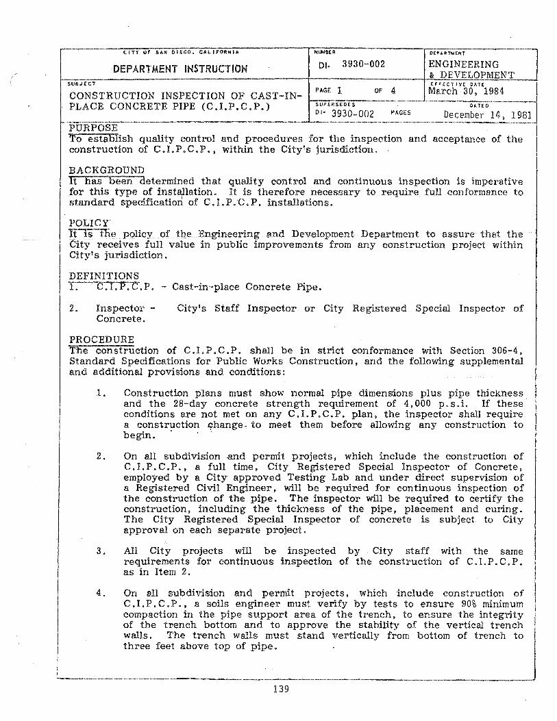
CITY or SAN DIEGO. CALIFORNIA Nuo.cBER
01. 3930-002 ENGINEERING &. DEVELOPMENT DEPARTMENT INSTRUCTION
SUBJECT ErF(CT IVE DATE
CONSTRUCTION INSPECTION OF CAST-INPLACE CONCRETE PIPE (C.LP.C.P.)
PAGE 1 SUPERSEDES
DI- 3930-002
OF 4 March 30. 1984 DATED
PAGES December 14. 1981 PURPOSE To establish quality control and procedures for the inspection and acceptance of the construction of C.LP.C.P .• within the City's jurisdiction.
BACKGROUND It has been determined that quality control and continuous inspection is imperative for this type of insta,llation. It is therefore necessary to require full conformance to stan dard specification of C. 1. P. C. P. installations.
POLICY It is the policy of the Engineering and Development Department to assure that the City receives full value in public improvements from any construction project within City's jurisdiction.
DEFINITIONS 1. C. 1. P. C. P. - Cast-ill-place Concrete Pipe.
2. Inspector -Concrete.
City's Staff Inspector or City Registered Special Inspector of
PROCEDURE The construction of C. I. P • C. P. shall be in strict conformance with Section 306-4. Standard Specifications for Public Works Construction. and the following supplemental and additional provisions and conditions:
1. Construction plans must show normal pipe dimensions plus pipe thickness and the 2S-day concrete strength requirement of 4.000 p. s. i. If these conditions are not met on any C. 1. P. C. P. plan, the inspector shall require a construction ~hange. to meet them before allowing any construction to begin.
2. On all subdivision .and permit projects. which include the construction of C. I. P . C. P.. a full time. City Registered Special Inspector of Concrete. employed by a City approved Testing Lab and under direct supervision of a Registered Civil Engineer, will be required for continuous inspection of the construction of the pipe. The inspector will be required to certify the construction, including the thickness of the pipe. placement and curing. The City Registered Special Inspector of concrete is subject to City approval on each separate project.
...
3. All City projects will be inspected by City staff with the same requirements for continuous inspection of the construction of C. I. P. C. P. I
as in Item 2. I 4. On all subdivision and permit projects. which include construction of !
C . I . P . C • P .• a soils engineer must verify by tests to ensure 90% minimum I compaction in the pipe support area of the trench. to ensure the integrity I,'
of the trench bottom and to approve the stability of the vertical trench walls. The trench walls must stand vertically from bottom of trench to three feet above top of pipe.
139
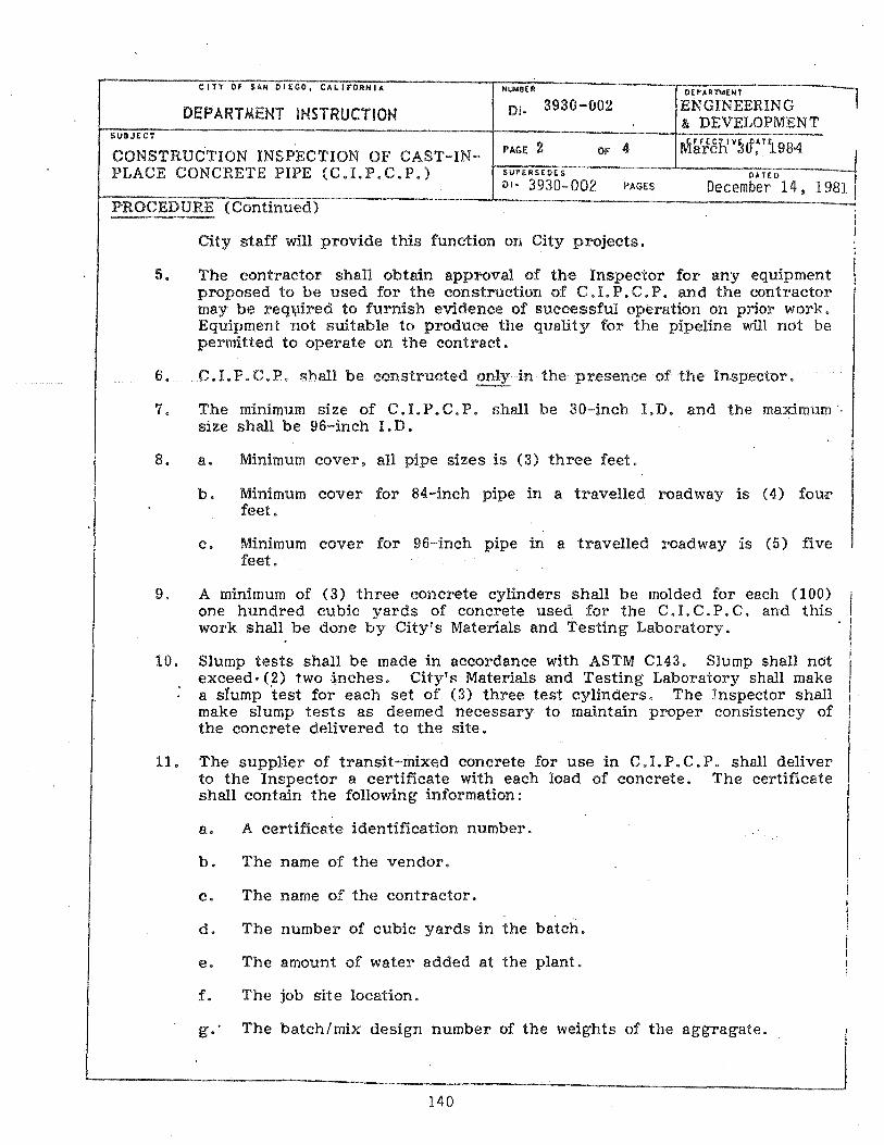
CITY Of SAM OIEGO, CA~lrOANIA NUIoI8£R D£P~RTldENT
ENGINEERING 8. DEVELOPMENT
1 DEPARTMENT INSTRUCTlON 01. 3930-002
SUBJECT
CONSTRUCTION INSPECTION OF CAST-INPLACE CONCRETE PIPE (C.LP.C.P.)
PAGE 2 OF 4 SUPERSE DE S
01- 3930-002 PAGES DATEO 1
December 14. 1981 I PROCEDURE (Continued)
City staff will provide this function on City projects.
5. The contractor shall obtain approval of the Inspector for any equipment proposed to be used for the construction of C.!. P. C. P. and the contractor may be req1jlired to furnish evidence of successful operation on prior work. Equipment not suitable to produce the quality for the pipeline will not be permitted to operate on the contract.
6.
7.
8.
C. I. P. c. P. shall be constructed only in the presence of the Inspector.
The minimum si ze of C. 1. P. C. P. shall be 30-inch 1. D. and the maximum size shall be 96-inch 1. D.
a. Minimum cover. all pipe sizes is (3) three feet.
b. Minimum cover for 84-inch pipe in a travelled roadway is (4) fou;r' feet.
c. Minimum cover for 96-inch pipe in a travelled roadway is (5) five feet.
9. A mmlmum of (3) three concrete cylinders shall be molded for each (100) I one hundred cubic yards of concrete used for the C. I. C. P. C. and this
I
10.
11.
work shall be done by Cityfs Materials and Testing Laboratory. i
Slump tests shall be made in accordance with ASTM C143. Slump shall not exceed- <,2) two ·~nches. City's Materials and Testing Laboratory shall make a sTump test for each set of (3) three test cylinders. The Inspector shall make slump tests as deemed necessary to maintain proper consistency of the concrete delivered to the site.
I
I ! I
The supplier of transit-mixed concrete for use in C. I. P. C. P. shall deliver to the Inspector a certificate with each load of concrete. The certificate shall contain the following information: I
a. A certificate identification number.
b. The name of the vendor.
c. The name of the contractor.
d. The number of cubic yards in the batch.
e. The amount of water added at the plant.
f. The job site location.
g.' The batch/mix design number of the weights of the aggragate.
140

CITY or SAN DIEGO, CAklFORNIA NUiolBER
01. 3930-002
PAGE: 3 OF 4 SUP£RS£DES
DI- 3930-002 PAGES
OEPHIThlENT
EFFECT IV~'pATE March ~U, 1984
DATE 0
December 14,
/
I 11. (Continued)
12.
13.
14.
h. The amount of water added at the job.
i. The cement type.
j. The brand iand amount of admixture used.
k. The time and date of bat ching.
1. The time of discharging.
m. The re'volution count (start and stop)
Two gallons of water per cubic yard of concrete shall be withheld from each load so that additional water can be added at the job site and mixed into the load for a minimum mixing time of three (3) minutes before discharging.
'Concrete shall be delivered and deposited in its final position within a period of 90-minutes after the addition of mixing water at the batch plant. Concrete that is too wet or has taken a partial set will be rejected by the Inspector.
The temperature of the fresh concrete shall not be more than 90-degrees FO and not less than 50-degrees FO. The Inspector shall check the loads for temperature.
The thickness of C. I. P. C. P. shall be measured after construction at the top. at I
the bottom, and at points 45-degrees each side of top and bottom. Test holes I for measuring- thickness,· shall be at the rate of one set of holes for each 50-feet. 'or fraction thereof. of pipe placed. i
1
The Inspector shall remain on the job site until all initial concrete curing operations have been accomplished.
/
During construction of the C. 1. P. C. P.. a daily Inspection Report will be required of the Inspector and shall be submitted to the City's Construction Engineer. The Inspection Report shall include:
I I
a.
b.
c.
d.
Trench conditions. such as. in cut or fill, % compaction. and stability of I bottom and sides. i
Observed alignment and grade tolerances of pipe. i I
i Method of curing of the concrete. i Notation that all ~7days.
~\ ( it 1ft )
I
pipe openings are closed, and kept closed for at least i i
141

CITY or SAN DIEGO, CALIfORNIA NUI4BER DEP~R""ENT
DI- 3930-002 ENGINEERING DEPARTMENT INSTRUCTION & DEVELOPMENT
SU8JECT
CONSTRUCTION INSPECTION OF CAST-INPLACE CONCRETE PIPE (C.LP.C.P.)
PAGE 4 OF
SUPERSEDES 01- 3930-002
4
PAGES
e. Repairing of pipe in accordance with specifications.
f. Location» width» and length of any cracking in the pipe.
EFFECTIVE OAn March 30. 1984
DAHO
December 14,
g. Log of test cylinders taken and truck ticket number samples taken from.
h. Slump tests and truck ticket number from which tests were taken. I
1981
. 1. Location and actual thickness of pipe at test sites for top» bottom» and 45-degrees each side of top and bottom.
j. Location and actual thickness of any concrete cores when required.
k. Location and results of any required load bearing test.
15. S,torm water shall not enter the pipe until the 28 day strength is reached and the trench is backfilled.
16. After construction of the C. I. P. C. P. is complete» and Inspection Report by the Inspector shall be submitted to the Construction Engineer of any sampling or testing on the C. I. P. C. P. within one week of any such sampling or testing.
17. The Inspector shall gather all testing data and shall submit a final Inspection Report to the Construction Engineer certifying that the pipe was constructed in conformance with the specifications and has satisfactorily passed all tests.
142
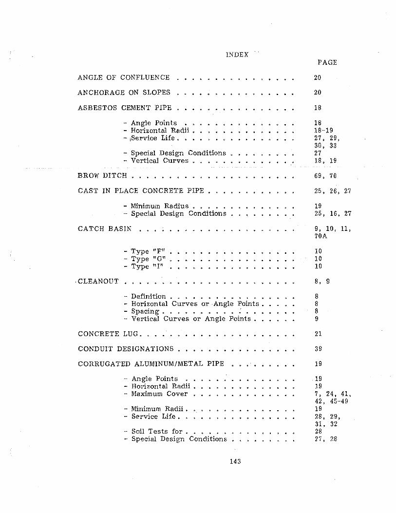
INDEX
ANGLE OF CONFLUENCE
ANCHORAGE ON SLOPES
ASBESTOS CEMENT PIPE •
- Angle Points - Horizontal Radii. • - jService Life. • • •
- Special Design Conditions • - Vertical Curves
BROW DITCH
CAST IN PLACE CONCRETE PIPE •.
- Minimum Radius • • . • • • - Special Design Conditions •
CATCH BASIN •• es ••••••• O.".
- Type "F" - Type "Gil - Type "I"
·CLEANOUT
- Definition . . • • • • • • • • • • - Horizontal Curves or Angle Points. • • • • - Spacing. 0 • " @ II) III • • e
- Vertical Curves or Angle Points.
CONCRETE LUG. • • • .
CONDUIT DESIGNATIONS
CORRUGATED ALUMINUM/METAL PIPE
- Angle Points • • . • • • • - Horizontal Radii. • • . • . - Maximum Cover
- Minimum Radii. - Service Life. •
- Soil Tests for . . • . . - Special Design Conditions
143
PAGE
20
20
18
18 18-19 27. 29, 30, 33 27 18, 19
69, 70
25, 26, 27
19 25, 16, 27
9, 10, 11. 70A
10 10 10
8, 9
8 8 8 9
21
39
19
19 19 7, 24,41, 42, 45-49 19 28, 29, 31, 32 28 27, 28

INDEX (Continued)
CROSS GUTTER.
CURB INLET
- Apron for. • • • • - Capacity . • • • • - .Maximum Opening • • • • • - 'Minimum Opening - Type "Aft
Type "B" Type "C" Type "DtI • . • • • •
- Type "E" - Type "HI! - Type flJtf
D-25 - D-27
CURTAIN WALL.
CUTOFF WALL
DESIGN CRITERIA ••
DESILTING BASIN
D-LOAD
DRAINAGE STUDIES
EASEMENTS.
- Access • . " • . e & • •• (II • •
- Join t Use . III • • • • • • • • • ... • •
- Minimum Widths • • • • • • • • - S pedal Easement Widths
ENERGY DISSIPATOR .
FENCING
HEADWALL
144
PAGE
24
9, 10, 11, 12, 70A
10 10, 12 10 10 9 9 10 10 10 10 10 10 10
20
20
23, 24, 25
22. 119-130
23. 41, 43, 44
3. 4, 5, 6 40. 41
40 40 40 40. 41
22
22, 65, 71, 72
21
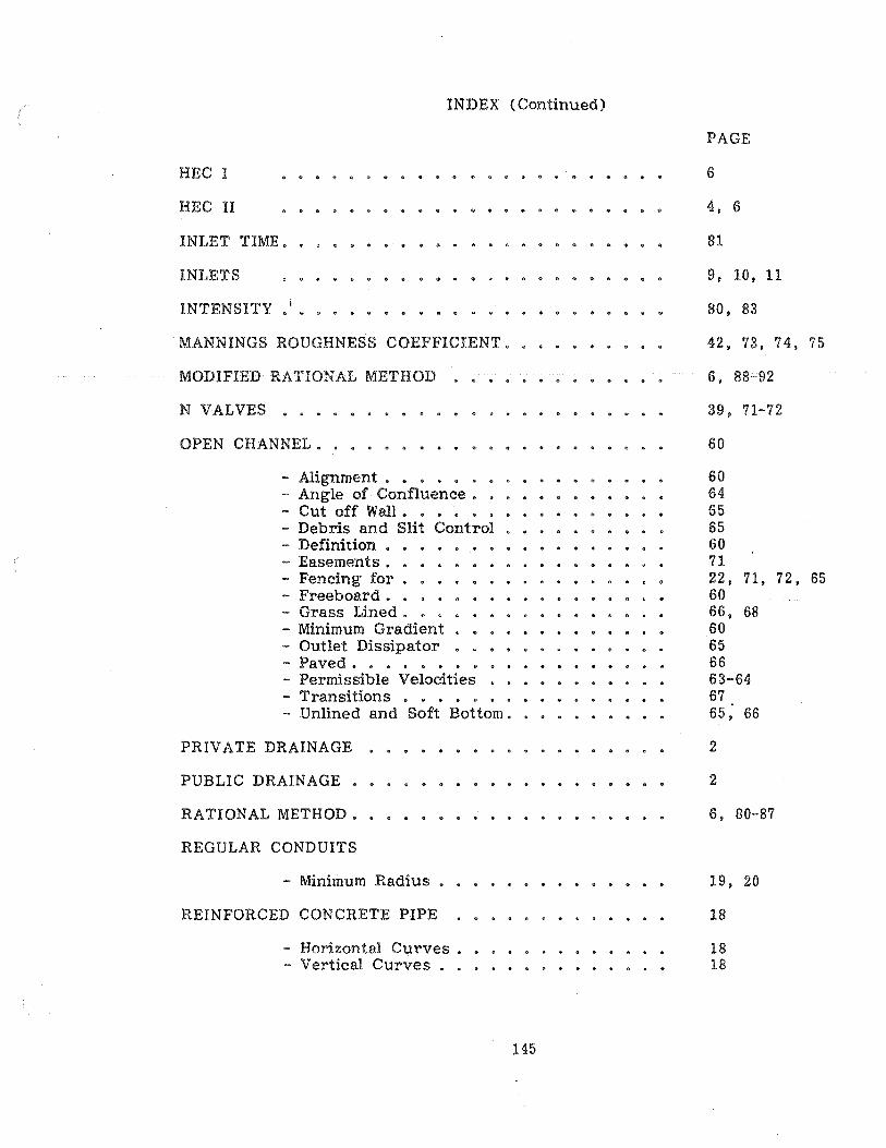
INDEX (Continued)
HEC I
HEC II
INLET TIME ••
INLETS
INTENSITY
. MANNINGS ROUGHNESS COEFFICIENT.
MODIFIED RATIONAL METHOD
N VALVES ••••
OPEN CHANNEL. •
- Alignment. • • • • • - Angle of Confluence. - Cut off Wall. • - Debris and Slit Control • - Definition • • • - Easements •• - Fencing for • • - Freeboard. • • - Grass Lined. • • • - Minimum Gradient • • • • • - Outlet Dissipator • • • • ..... Paved. " . a • • •
- Permissible Velocities - Transitions • • • • • - Unlined and Soft Bottom.
PRIVATE DRAINAGE
PUBLIC DRAINAGE ••
RATIONAL METHOD ••
REGULAR CONDUITS
- Minimum Radius • •
REINFORCED CONCRETE PIPE
- Horizontal Curves. - Vertical Curves . . .
145
PAGE
6
4, 6
81
9, 10, 11
80, 83
42 • 73, 74, 75
6, 88-92
39, 71-72
60
60 64 65 65 60 71 22, 71, 72, 65 60 66, 68 60 65 66 63-64 67 65; 66
2
2
6, 80-87
19. 20
18
18 18

INDEX (Continued)
RUNOFF COEFFICIENT • . •
ROUGHNESS COEFFICIENTS.
SCS METHOD ••••
SEEPAGE LINES.
SEEPAGE STA~EMENT.
SIGNALIZED INTERSECTION (CROSS GUTTERS)
SLOPE DRAINS • • • •
SLOTTED DRAIN PIPE
- Gage •• •• • • - Loading. • • . ••. - Maximum Length .•• - Minimum Pipe Grade • - Minimum Pipe Size • • - Minimum Slot Height. - Service Life. • - Trenching for.
STREET DRAINAGE.
STRUCTURAL STEEL Plate
-. Maximum Cover •
SUBDRAIN
TIME OF CONCENTRATION
TEE INTESECTIONS •
TOE DITCH .••
TRASH FENCE
TRAVEL TIME.
UNDERDRAIN •
WATER-TIGHT JOINTS
146
PAGE
80.82'
39, 71-72
6, 93-118
34
35. 36
24
20
11, 12
11 11 11 11 11 11 11 11
70, 70A
7. 47. 48
34-38
80, 84
11
70
22
81
2, 10, 50
23 "-