Embed Size (px)
Citation preview

336 Philips Tech. Rev. 42, No. 10/11/12,336-340, Sept. 1986
Electric motors in small domestic appliances
R. H. Dijken
Introduetion
After Oersted's discovery in 1820 that a force acts onan electric current in a magnetic field, the search wason for machines that could use this principle for con-verting electric power into mechanical power. The firstmachine that could be called a 'rotary electric motor'is probably Barlow' s wheel, dating from 1831 [1],
illustrated in fig. 1. The first practical rotary electricmotors appeared in about 1870, and were used fordriving water pumps in mines, for traction and otherapplications. These motors were rated at relativelyhigh powers, typically 5 kW or more. Other types ofelectric motor gradually emerged, with increasingefficiency, longer life and lower prime cost.
The first 'small' electric motors were designed inabout 1920. They wereseries-commutator motors usedin vacuum cleaners. Later other types of small electricmotor appeared, such as the d.c. commutator motorwith permanent magnet stator, the single-phase induc-tion motor and the single-phase synchronous motorwith permanent-magnet rotor.The early sixties marked the emergence of a fast-
growing market for electrical domestic appliances inWestern Europe. In that same period the Philipsgroup, which was already producing electric shavers,embarked on the production of a wide variety of elec-trical domestic appliances, most of them containingan electric motor.In the following we shall first consider the dif-
ferences between large and small electric motors, withreference to laws of scaling. We shall then look atsome of the leading developments in small electricmotors. Finally we shall consider their applications inPhilips products: series motors in vacuum cleanersand shavers, single-phase synchronous motors withpermanent-magnet rotors in hair trimmers, citruspresses, knife sharpeners, can openers and vibratoryshaving appliances, and d.c. commutator motors withpermanent-magnet stator in rotary-action shavers.
Dr Ir R. H. Dijken is with the Domestic Appliances and PersonalCare Division, Philips NPB, Groningen. If d is reduced while the values of i. Band n remain
J)
Fig. I. Barlow's wheel. The teeth of the wheel W dip into mercurybetween the poles of a horseshoe magnet HM. When current flowsthe wheel turns.
Differences between large and small electric motors
The power P of an electric motor with a wound I
rotor can be expressed in terms of the current density jin the rotor windings, the air-gap flux density (or ,induction) B, the speed of rotation n and the rotordiameter d [21:
(1)
The copper loss Pc« in the rotor is related to j and dby:
(2)
From (1) and (2) we have:
Peu j--CX:--.
P Bnd(3)

Philips Tech. Rev. 42, No. 10/11/12 SMALL ELECTRIC MOTORS 337
unchanged, the ratio Peul P increases. This meansthat the efficiency of a small motor becomes lower andits torque-speed characteristic less steep [31. One con-sequence of this for the designer is that the currentdensity j must be reduced as the size of the motor isdiminished.
Apart from many other differences between 'large'and 'small' electric motors, there is a difference con-nected with the cooling. The heat generated in therotor has to flow from the interior before it can bedissipated from the surface. The resulting tempera-ture difference between the interior and the surface ofthe rotor is approximately proportional to d2• For arotor diameter smaller than about 10 cm this tempera-ture difference remains small compared with the per-missible rise in the temperature of the rotor. At largerrotor diameters the interior of the rotor could becomedangerously hot. There are therefore two coolingproblems with the large electric motor, one relating toheat transfer from inside the rotor to the surface, andthe other relating to heat dissipation from the rotorsurface. The small electric motor only has to contendwith the second cooling problem.
These critical factors (and many others) indicatethat the line of demarcation between large and smallelectric motors corresponds roughly to a rotor diam-eter of 10 cm and a power of 1000 W.
Developments
We shall now consider some innovations in tech-nology and materials that have largely determined thepattern of development of small electric motors inPhilips domestic appliances from 1960 to the presentday.
Insulation of the windings
The rotor and stator windings have to be electricallyinsulated from the laminated cores. The quality of theinsulation must be high. In 1960 the insulation wasprovided by paper strips, stars and formers, as shownon the left in fig. 2, and these were gradually replacedby plastic. Nowadays, separate plastic insulators areused, and these are attached to the laminated core. Insome cases the laminated cores are placed in a mouldand surrounded by plastic injected in the mould.Plastics provide better insulation, reduce the numberof components required and facilitate mechanicalassembly. An example of plastic insulation in a shaverrotor is shown on the right in fig. 2. This rotor hasthree lobes, each with a winding around it. If paperinsulation were used, the turns of the winding wouldreceive little support, and the coils would thereforehave to be impregnated. The injection-moulded plastic
Fig. 2. The rotor of a series motor for a hand mixer is shown on theleft. The laminated core is insulated with paper and plastic. On theright is the rotor of a series motor for a Philishave. The injection-moulded plastic around the core acts as a triple former for thewindings.
around the rotor core produces a 'former', so thatimpregnation is not required.
Permanent-magnet materials
Scaling laws show that the stator windings of acommutator motor become heavier, larger and moreexpensive in relation to the total weight, volume andcost of the motor as the dimensions are scaled down.If the supply is d.c., there is much to be said for usingpermanent-magnet stators. Before 1960 the only suit-able magnets were those made of steel alloys such asTiconal. Although these materials have a high reman-ent flux density, about 1 T (tesla), they have two greatdisadvantages: their resistivity is low and they areeasily demagnetized. The gaps between the rotor lobesmake the reluctance of the magnetic circuit dependenton the position of the rotor, so that the flux from themagnet varies periodically as the rotor rotates. Thissets up fairly large eddy currents in the magnet, andthese adversely affect the efficiency of the motor. Sincethe magnet is easily demagnetized - and for otherreasons - its volume must be relatively large, and thismakes the motor heavy, bulky and expensive.
In about 1960 the sintered anistropic iron oxideFerroxdure became available. Although its remanentflux density is much smaller than that of Ticonal,about 0.35 T, Ferroxdure has such a high resistivitythat the eddy currents are negligible. Other advantagesare that its density is low, it is difficult to demagnetizeand it is relatively inexpensive. All these advantages
(IJ B. Bowers, The early history of the electric motor, PhilipsTech. Rev. 35, 77·95, 1975.
(2J R. H. Dijken, Similarity relations for small electric motors,Proc. Symp. on Electrical machines for special purposes,Bologna 1981, pp. 439-447.
(3J R. H. Dijken, Optimization of small AC series commutatormotors, Thesis, Eindhoven 1971.
338 R. H. DIJKEN Philips Tech. Rev. 42, No. 10/11/12
account for a total annual world production of morethan 500 million small commutator motors with mag-nets of Ferroxdure or similar materials.
The commutator
After 1960there was a relatively marked increase inthe number of d.c. commutator motors for supplyvoltages lower than 6 V. At these low voltages graphitebrushes are not satisfactory: they have a voltage dropof a few volts and the high pressure of the brushesgives high friction. Brushes of copper graphite orsilver graphite have a much smaller voltage drop, butthey cause just as much friction as graphite brushes.Brushes and commutators both made of a noble-metalalloy provided the solution. The low brush pressuregives low friction, and the contact resistance betweenbrushes and commutator is virtually negligible.
Examples of the evolution of some types of motor
The a.c. series motor in vacuum cleaners
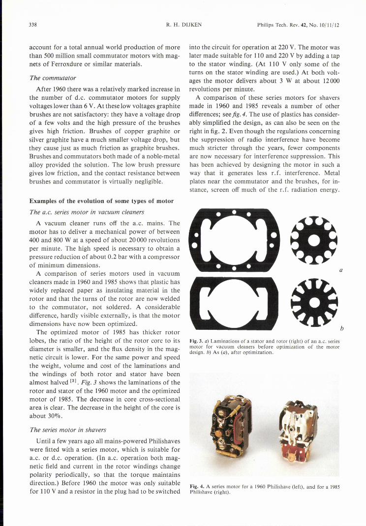
A vacuum cleaner runs off the a.c. mains. Themotor has to deliver a mechanical power of between400 and 800 W at a speed of about 20000 revolutionsper minute. The high speed is necessary to obtain apressure reduction of about 0.2 bar with a compressorof minimum dimensions.A comparison of series motors used in vacuum
cleaners made in 1960 and 1985 shows that plastic haswidely replaced paper as insulating material in therotor and that the turns of the rotor are now weldedto the commutator, not soldered. A considerabledifference, hardly visible externally, is that the motordimensions have now been optimized.
The optimized motor of 1985 has thicker rotorlobes, the ratio of the height of the rotor core to itsdiameter is smaller, and the flux density in the mag-netic circuit is lower. For the same power and speedthe weight, volume and cost of the laminations andthe windings of both rotor and stator have beenalmost halved [3] • Fig.3 shows the laminations of therotor and stator of the 1960 motor and the optimizedmotor of 1985. The decrease in core cross-sectionalarea is clear. The decrease in the height of the core isabout 30070.
The series motor in shavers
Until a few years ago all mains-powered Philishaveswere fitted with a series motor, which is suitable fora.c. or d.c. operation. (In a.c. operation both mag-netic field and current in the rotor windings changepolarity periodically, so that the torque maintainsdirection.) Before 1960 the motor was only suitablefor 110V and a resistor in the plug had to be switched
into the circuit for operation at 220 V. The motor waslater made suitable for 110 and 220 V by adding a tapto the stator winding. (At 110 V only some of theturns on the stator winding are used.) At both volt-ages the motor delivers about 3 W at about 12000revolutions per minute.A comparison of these series motors for shavers
made in 1960 and 1985 reveals a number of otherdifferences; seefig. 4. The use of plastics has consider-ably simplified the design, as can also be seen on theright in fig. 2. Even though the regulations concerningthe suppression of radio interference have becomemuch stricter through the years, fewer componentsare now necessary for interference suppression. Thishas been achieved by designing the motor in such away that it generates less r.f. interference. Metalplates near the commutator and the brushes, for in-stance, screen off much of the r.f. radiation energy.
a
b
Fig. 3. a) Laminations of a stator and rotor (right) of an a.c, seriesmotor for vacuum cleaners before optimization of the motordesign. b) As (a), after optimization.
Fig. 4. A series motor for a 1960 Philishave (left), and for a 1985Philishave (right).

Philips Tech. Rev. 42, No. 10/11/12 SMALL ELECTRIC MOTORS 339
Fig. S. A single-phase synchronous motor with permanent-magnet rotor and some Philipsproducts in which this motor is used: two knife-sharpeners (left), a hair-trimmer (centre) and twocitrus-presses (right).
The brush springs are designed to function as r.f.chokes, and the stator windings are dimensioned toresonate with their own stray capacitance as parallelLC circuits, presenting a high impedance at criticalinterference frequencies.
The single-phase synchronous motor with permanent-magnet rotor
Although the principle of this motor has long beenknown, some practical problems prevented its appli-
cation. The magnet material used has to have a rel-atively high coercive force. Ferroxdure provided theanswer to this problem in about 1960. A second prob-lem was that the motor can only rotate at a speed thatcorresponds exactly to the frequency of the a.c.mains. As soon as the appliance is switched on, therotor must therefore rotate synchronously within onemains period of switching on. The solution was foundby giving the rotor the correct moment of inertia andshaping the stator poles so that the rotor has a definedmagnetic preferential position when it is stationary.
A third problem is that of dynamic instability. Thisrefers to a periodic speed variation that can become sogreat that the rotor 'falls out of step' with the alter-nating stator field. In large electric machines thedynamic-instability problem is solved by fitting aninduction cage. Scaling laws show that this does nothelp for small single-phase synchronous motors.Nevertheless, after years of research, a solution to the
dynamic instability problem was found for this typeof motor as well [41. A final, and as yet unsolved,problem is that after switching on, it remains to beseen which way the motor starts to rotate. The motorcan therefore only be used for applications where thisdoes not matter. The Philips single-phase synchronousmotor with permanent-magnet rotor has so far beenused in vibrator shavers, hair-trimmers, citrus-presses,knife-sharpeners, shoe-polishers, can-openers, cork-screws and ice-cream makers; jig. 5.
The d. c. commutator motor with permanent-magnetstator
In about 1960 mains-powered Philishaves operatingwith batteries or rechargeable nickel-cadmium cellsbecame available as well as the mains-operated ver-sions. The natural choice of the motor for the shaversoperating with batteries or cells was the d.c. com-mutator motor with permanent-magnet stator. Inrecent years this motor has started to supersede theseries motor in mains-operated Philishaves. The d.c.supply it requires is derived from the a.c. mains by anelectronic circuit.
To get the maximum number of shaves from a bat-tery or a rechargeable NiCd cell, the motor must have[4] H. Schemmann, Stability of small single-phase synchronous
motors, Philips Tech. Rev. 33, 235-243, 1973;H. Schemmann, Theoretische und experimentelle Untersuchun-gen über das dynamische Verhalten eines einphasen-Synchron-motors mit dauermagnetischem Läufer, Thesis, Eindhoven1971, also published as Philips Res. Rep. Suppl. 1971, No. 5(in German).

340 SMALL ELECTRIC MOTORS Philips Tech. Rev. 42, No. 10/11/12
Fig. 6. Different versions of a d.c. commutator motor with permanent-magnet stator. A 1960design with two Ticonal blocks (left). A later design with two Ferroxdure magnets (not visible)with steel 'pole-arcs' (centre). A design dating from the seventies with a Ferroxdure ring, later re-placed by two Ferroxdure segments (right). (The motor is shown dismantled: the plate with nob le-metal fingers is in the foreground, the magnet in the centre and the rotor in the background.)
the highest possible efficiency. High efficiency is there-fore the key feature of the design. Since 1960 theefficiency of the motor has gradually been increasedfrom about 25070to about 65%. Three developmentsmade this possible. The first is the use of better mag-net materials. Ticonal was still being used in 1960. As
can be seen on the left in jig. 6, Ticonal magnets werecast as blocks, which were fitted to the soft-ironstator . Ferroxdure gave a great improvement in effi-ciency. The motor shown centrally in fig. 6 had Fer-roxdure blocks and steel 'pole-arcs' to conduct theflux through the rotor. Although there were someeddy current losses in these pole-arcs, they were lessthan in the motor with Ticonal. The technology ofmaking Ferroxdure in complex shapes was still advan-cing, and in about 1970 the blocks were replaced byrings, shown on the right in fig. 6. These rings consistof a plastic filled with anisotropic Ferroxdure powder.This arrangement virtually eliminated the eddy-cur-rent losses. Later on the ring was replaced by two seg-ments.
The second development that improved the effi-ciency was the replacement of the carbon brushes on
a copper commutator, first by pieces of phosphor-bronze on a noble-metal commutator and later bynoble-metal fingers on a noble-metal commutator; seefig. 6, right. The contact resistance between brushesand commutator and the brush-friction losses arevirtually zero with the noble-metal combination.
Finally, further improvement in efficiency was ob-tained by optimizing the design of the motor [51. Theratio of lobe width to rotor diameter and the ratio ofthe height to the diameter of the rotor core played aparticularly important part in this optimization.
[51 R. H. Dijken, Designing a small DC motor, Philips Tech. Rev.35, 96-103, 1975.
Summary. In addition to optimization via theoretical consider-ations, developments since 1960 in small electric motors used inPhilips domestic appliances include: improved insulation of thewindings, better permanent-magnet materials, lower friction andlower contact resistance between brushes and commutator. Thesedevelopments are illustrated by the evolution of the a.c. seriesmotor in vacuum cleaners, the series motor in Philishaves, thesingle-phase synchronous motor with permanent-magnet rotor invarious domestic appliances, and the d.c. commutator motor withpermanent-magnet stator in shavers for mains and battery oper-ation.

Philips Tech. Rev. 42, No. 10/1 1/12, Sept. 1986 341
Philips Technical Review 50 years agoAPRIL 1936 THE V.R. 18 TRANSMITTING AND RECEIVING EQUIPMENT
By c. ROMEYN.
With the progreeeing development of commer-cial flying, the need for some means of intercom-munication between an aircraft in flight and theairport very 800n became apparent, and the first
passenger and commercial airplanes, although stillvery small, were already equipped with wirelessapparatus. With the steady and radical improve-ments in technical methods and apparatus duringthe last ten years both flying and wireless
technology have made rapid strides. The impor-tance of wireless iuterccmmunica t ion during flighthas progressively increased and al the present day
it is impossible to conceive of a passenger or
commercial aircraft being without wirelessapparatus. Reports of weather conditions alongthe aircraft route, landing instructions, direction-
finding signals, etc., have become indispensableto the pilot.It is the task of the wireless industry to provide
suitable apparatus capable of meeting the specialrequirements for use in modern aircraft. That anaircraft radio equipment in many respects mustdiffer fundamentally from a permanent andstationary ground equipment is obvious. In thepresent article the V. R. 18 aircraft transmitting-receiving equipment designed by Philips isdescribed. This equipment has heen speciallyevolved to meet the various requirements for useaboard aircraft, yet in its design attention has,moreover, been given to certain specialised needsconsidering the application of this equipment forthe Douglas air liners operating on the Nether-lands East Indiee route of the K.L.M. air services.
Intercommunicanon between aircraft and air-port is nowadays performed almost exclusively bytel e g rap h i c means. In this connection it isinteresting to review briefly the historical develop-ment of the methods employed. During the earlyyears of flying intercommunication with aircraftwas carried out solely by means of the tel e -ph 0 n e. This instrument alone could be used althat time, since the pilot who had to operate thewireless apparatus already had both hands Iull yoccupied in controlling the flight of the machineand it was thus impossible for him to work a Morsekey. The disadvantages of using telephony became,
however, steadily more apparent. In the first place,to cover the eame range a telephone transmitterhas to have a greater power than a telegraph trans-mitter; yet the most serious drawback of telephonyis that it requires a wider frequency band, since,owing to modulation, an additional side band istransmitted at both sides of the carrier-wave fre-quency. In view of the increasing number of trans-mitting stations, which were concemreted in a
comparatively small geographical area, the fewfrequency bands available were 800n taken up. Theonly practical means for avoiding intensive mutualinterf erenee of stations was to adopt the tele-graphic method of intercommunication. Thismade it necessary to provide a wireless operatorfor each aircraft in addition to the pilot. Thisaddition to the crew would, however, have becomenecessary fOTother reasons, even without changingover from the telephone to the Morse key. Thegreater demands made on the pilot. by the morecomplex problems associated with navigation(flying at night and through fog) were alreadymaking the care of the telephone an onerousadditional responsibility, while on the other handwireless intercommunication' for the self-samereason, viz, the much-increased number of reportsrequired for safe navigation, itself demanded closerattention. Moreover, it had become practicable tocarry a special operator, as larger aircraft werebeing built in which more room was provided inthe pilot's cabin.
Intercommunication between aircraft and a ir-ports is thus at the present time almost exclusivelybased on tel e g r a p h y. By international agree·ment the wave-lengths of 600, 944, 918 and 932 m
have been allocated for wireless aircraft t runs-miners, of which the 600-m wave-length is on lyallowed for t ransocennic flights.Installation of EquipmentThe transmitter with the associated converter is
uccommodated in a corner of the luggage cabin.It is suspended by shock-absorbing cables and isthus adequately protected against. jolts and vibra-tion, The receiver is set up on sjHing rubbersupports in front of the operator's seat (jig. 6),toget her with the control box, on which are
JULY 1936 IRRADIATION OF PLANTS WITH NEON LIGHT
By J. W. M. ROODENBURG and G. ZECHER.
After decades of abortive exper-imen ts in theNetherlands and elsewhere on the ar tificial irradi-ation of plants, an appreciable measure of successhas recently been achieved in this direction. ThatIighl is one of the principal factors in the growthof plants has heen realised for many years, andthe idea has long been entertained of attempting
to influence the growth and development of plantsby irradiation with artificial light. But only withthe technical development of the requisite sourcesof light has a fundamental investigation of thisproblem been made possible and enabled the marketgrower and amateur hor-ticulturist to employirradia t ion methods on a practical scale.
Fig, 3. Star of Bethlehem (Campanula isophylla). Picture taken on February 5, 1934.Left: Irradiated with neon light, 600 lux, each night from 10 p.m. to 6 a.m. fromNovember 2, 1933, to January 25, 1934. Right: plants non-irradiated.
Fi!!:.3. V,Z. IS tt-un stuitt er with ~·ha~si:;drawn out and frontwall removed. The housi ng und r-hassis are made of dur-alumin.
arranged, among other items, the Morse keys,various switches and the aerial ammeter. For nightflying, dial illumination is provided, being capableof regulation and so placed that it does not inter-fere with the pilot's field of vision.
Fig. 6. Installation of the receiver (ubovc) and the controlIJOX (below) in front of the wireless operator in the pilot'scahin of a Douglas air liner.
The life and growth of plants are intimatelyconnected with certain chemical processes. One ofthe chief of these is the assimilation of carbondioxide, in the course of which the plants absorbcarbon dioxide from the air and the carbohydratesfrom the water of which plants are principallybuilt up. Carbon dioxide assimilation takes placeonly when a light stimulus is provided, the lightbeing absorbed by the green colouring matter ofthe leaves, viz, chlorophyll. If the light availablefor the plant drops below a specific level, e.g.during the short days of winter, growth is practi-cally static, even though all other conditions fortheir growth are adequately met, as for instanceby placing in heated and moist greenhouses andby the addition of suitable fertilisers.
By augmenring the natural light with anauxiliary source of illumination, it has now hee-npossible to promote the growth of plants evenduring the darkest winter months.
Carbon dioxide assimilation is most active inred light, which is absorbed to a high degree bychlorophyll. Hence, inproviding auxiliary irradiationfor plants, it is essenrial to utilise a source of lightcontaining a sufficient concen tra tion of red rays.At an early date it was therefore proposed toemploy neon light for this purpose .