Embed Size (px)
Citation preview
R E G E N C YModel 2615 Control/Communicator
Installation Manual
Part Number 150863, Rev. AInitial Release Date: March 1995
Revised August 1998

Visit our website at www.ititechnologies.com
ITI and Regency are registered trademarks of Interactive Technologies, Inc.ITI © 1998. All rights reserved.
For reprints, order manual: 150863, Revision A
T : 6 5 1 / 7 7 7 - 2 6 9 0
F : 6 5 1 / 7 7 9 - 4 8 9 0
Interactive Technologies, Inc.
2 2 6 6 S e c o n d S t r e e t N o r t h
N o r t h S a i n t P a u l , M N 5 5 1 0 9 - 2 9 0 0
Security
Automation
Fire Protection
Access Control
OET HC N SGOL IE

FCC Notices
Regency® Model 2615 Control Communicator Installation Manual (P/N 150863, Rev. A) Revised 8/98
i
FCC Part 15 Information to the UserChanges or modifications not expressly approved by Interactive Technologies, Inc. can void the user’s authority to operate the equipment.
FCC Part 15 Class BThis equipment has been tested and found to comply with the limits for a Class B digital device, pursuant to part 15 of the FCC Rules. These limits are designed to provide reasonable protection against interfer-ence in a residential installation.
This equipment generates, uses, and can radiate radio frequency energy and, if not installed and used in accordance with the instructions, may cause harmful interference to radio communications. However, there is no guarantee that interference will not occur in a particular installation.
If this equipment does cause harmful interference to radio or television reception, which can be determined by turning the equipment off and on, the user is encouraged to try to correct the interference by one or more of the following measures:
■ Reorient or relocate the panel’s receiving antenna.■ Increase the separation between the equipment and receiver.■ Connect the affected equipment and the panel receiver to separate outlets, on different branch
circuits.■ Consult the dealer or an experienced radio/TV technician for help.
FCC Part 68This equipment complies with part 68 of the FCC Rules. Located on this equipment is a label that contains, among other information, the FCC registration number and the ringer equivalence number (REN) for this equipment. If requested, this information must be provided to the telephone company.
The REN is used to determine the maximum number of devices that may be connected to your telephone line. In most areas, the sum of all device RENs should not exceed five (5.0).
If this equipment causes harm to the telephone network, the telephone company may temporarily discon-nect your service. If possible, you will be notified in advance. When advance notice is not practical, you will be notified as soon as possible. You will also be advised of your right to file a complaint with the FCC.
Your telephone company may make changes in its facilities, equipment, operations, or procedures that could affect the proper operation of your equipment. You will be given advance notice in order to maintain uninterrupted service.
If you experience trouble with this equipment, please contact the company that installed the equipment for service and repair information. The telephone company may ask you to disconnect this equipment from the network until the problem has been corrected or you are sure that the equipment is not malfunctioning.
This equipment may not be used on coin service provided by the telephone company. Connection to party lines is subject to state tariffs.
Regency® Model 2615 Control Communicator Installation Manual (P/N 150863, Rev. A) Revised 8/98
Table of Contents
ii
Section 1 Introduction . . . . . . . . . . . . . . . . . . . . . . . . . . . . . . . . . . . . . . . . . . . . . . . . . . 1
1.1 How to Use This Manual . . . . . . . . . . . . . . . . . . . . . . . . . . . . . . . . . . . . 1
1.2 How to Contact Interactive Technologies, Inc. . . . . . . . . . . . . . . . . . . . 1
1.3 Optional Accessories . . . . . . . . . . . . . . . . . . . . . . . . . . . . . . . . . . . . . . . 1
Section 2 Specifications . . . . . . . . . . . . . . . . . . . . . . . . . . . . . . . . . . . . . . . . . . . . . . . . . 3
2.1 Electrical Specifications . . . . . . . . . . . . . . . . . . . . . . . . . . . . . . . . . . . . . 3
2.2 Environmental Specifications . . . . . . . . . . . . . . . . . . . . . . . . . . . . . . . . . 3
Section 3 Agency Requirements . . . . . . . . . . . . . . . . . . . . . . . . . . . . . . . . . . . . . . . . . . 4
3.1 Telephone Requirements . . . . . . . . . . . . . . . . . . . . . . . . . . . . . . . . . . . . 4
3.2 FCC Warning . . . . . . . . . . . . . . . . . . . . . . . . . . . . . . . . . . . . . . . . . . . . . 4
3.3 UL Requirements . . . . . . . . . . . . . . . . . . . . . . . . . . . . . . . . . . . . . . . . . . 5
Section 4 Control Panel Description and Installation . . . . . . . . . . . . . . . . . . . . . . . . . 7
4.1 Board Layout . . . . . . . . . . . . . . . . . . . . . . . . . . . . . . . . . . . . . . . . . . . . . 7
4.2 Overcurrent Protection . . . . . . . . . . . . . . . . . . . . . . . . . . . . . . . . . . . . . . 7
4.3 AC Power Switch . . . . . . . . . . . . . . . . . . . . . . . . . . . . . . . . . . . . . . . . . . 8
4.4 Mounting the 2615 . . . . . . . . . . . . . . . . . . . . . . . . . . . . . . . . . . . . . . . . . 8
4.5 Terminal Strip Description . . . . . . . . . . . . . . . . . . . . . . . . . . . . . . . . . . . 8
4.6 Current Draw Worksheet . . . . . . . . . . . . . . . . . . . . . . . . . . . . . . . . . . . . 9
4.7 Zone Wiring . . . . . . . . . . . . . . . . . . . . . . . . . . . . . . . . . . . . . . . . . . . . . 11
4.7.1 Smoke Detector Wiring . . . . . . . . . . . . . . . . . . . . . . . . . . . . . . . . 12
4.8 Signaling Device Wiring . . . . . . . . . . . . . . . . . . . . . . . . . . . . . . . . . . . 13
4.8.1 Built-In Speaker Driver . . . . . . . . . . . . . . . . . . . . . . . . . . . . . . . . 13
4.8.2 External Siren Driver . . . . . . . . . . . . . . . . . . . . . . . . . . . . . . . . . . 13
4.8.3 Bell Wiring . . . . . . . . . . . . . . . . . . . . . . . . . . . . . . . . . . . . . . . . . 14
4.9 AC Power Transformer . . . . . . . . . . . . . . . . . . . . . . . . . . . . . . . . . . . . . 14
4.10 Backup Battery Connection (Model 6712) . . . . . . . . . . . . . . . . . . . . . . 15
Regency® Model 2615 Control Communicator Installation Manual (P/N 150863, Rev. A) Revised 8/98
Table of Contents
iii
4.11 Touchpad Installation . . . . . . . . . . . . . . . . . . . . . . . . . . . . . . . . . . . . . . 15
4.11.1Mounting the Touchpads . . . . . . . . . . . . . . . . . . . . . . . . . . . . . . . 15
4.11.2Touchpad Specifications . . . . . . . . . . . . . . . . . . . . . . . . . . . . . . . 16
4.11.3Wiring the Touchpads . . . . . . . . . . . . . . . . . . . . . . . . . . . . . . . . . 16
4.11.3.1 Daisy Chaining Touchpads . . . . . . . . . . . . . . . . . . . . . . 16
4.11.4Setting Touchpad ID Numbers . . . . . . . . . . . . . . . . . . . . . . . . . . 17
4.12 Telephone Line Connection . . . . . . . . . . . . . . . . . . . . . . . . . . . . . . . . . 18
4.13 Ground Start Relay (Model 2608) . . . . . . . . . . . . . . . . . . . . . . . . . . . . 18
4.14 4180 Status Display Module Installation . . . . . . . . . . . . . . . . . . . . . . . 19
Section 5 Basic System Operations . . . . . . . . . . . . . . . . . . . . . . . . . . . . . . . . . . . . . . . 22
5.1 Audible Signals . . . . . . . . . . . . . . . . . . . . . . . . . . . . . . . . . . . . . . . . . . . 22
5.2 Touchpad Basic Operation . . . . . . . . . . . . . . . . . . . . . . . . . . . . . . . . . . 24
5.2.1 Touchpad Function Buttons . . . . . . . . . . . . . . . . . . . . . . . . . . . . . 25
5.3 Setting Auto Test Time . . . . . . . . . . . . . . . . . . . . . . . . . . . . . . . . . . . . . 26
5.4 System Testing . . . . . . . . . . . . . . . . . . . . . . . . . . . . . . . . . . . . . . . . . . . 26
5.4.1 Walk Test . . . . . . . . . . . . . . . . . . . . . . . . . . . . . . . . . . . . . . . . . . . 27
5.4.2 Dialer Test . . . . . . . . . . . . . . . . . . . . . . . . . . . . . . . . . . . . . . . . . . 27
5.4.3 Touchpad/Bell Test . . . . . . . . . . . . . . . . . . . . . . . . . . . . . . . . . . . 27
5.5 Installer Operations Quick Reference . . . . . . . . . . . . . . . . . . . . . . . . . . 28
Section 6 Programming . . . . . . . . . . . . . . . . . . . . . . . . . . . . . . . . . . . . . . . . . . . . . . . . 29
6.1 Downloading . . . . . . . . . . . . . . . . . . . . . . . . . . . . . . . . . . . . . . . . . . . . . 29
6.2 Step Programming . . . . . . . . . . . . . . . . . . . . . . . . . . . . . . . . . . . . . . . . 29
6.2.1 Touchpad Operation . . . . . . . . . . . . . . . . . . . . . . . . . . . . . . . . . . 29
6.2.1.1 Entering Program Mode . . . . . . . . . . . . . . . . . . . . . . . . . . 30
6.2.1.2 How to Tell Which Step You Are Currently On . . . . . . . 30
6.2.1.3 Moving to a Different Step . . . . . . . . . . . . . . . . . . . . . . . 30
6.2.1.4 Moving to a Different Sub-Step . . . . . . . . . . . . . . . . . . . . 30
Regency® Model 2615 Control Communicator Installation Manual (P/N 150863, Rev. A) Revised 8/98
Table of Contents
iv
6.2.1.5 Entering Data . . . . . . . . . . . . . . . . . . . . . . . . . . . . . . . . . . 30
6.2.1.6 Correcting Errors . . . . . . . . . . . . . . . . . . . . . . . . . . . . . . . 30
6.2.1.7 Exiting Program Mode . . . . . . . . . . . . . . . . . . . . . . . . . . . 30
6.3 Programmable Options . . . . . . . . . . . . . . . . . . . . . . . . . . . . . . . . . . . . . 31
Section 7 Troubleshooting . . . . . . . . . . . . . . . . . . . . . . . . . . . . . . . . . . . . . . . . . . . . . . 54
7.1 Terminal Voltages . . . . . . . . . . . . . . . . . . . . . . . . . . . . . . . . . . . . . . . . . 54
7.2 Common Errors or Failures . . . . . . . . . . . . . . . . . . . . . . . . . . . . . . . . . 54
7.3 Viewing Trouble Conditions . . . . . . . . . . . . . . . . . . . . . . . . . . . . . . . . 54
Section 8 Reporting . . . . . . . . . . . . . . . . . . . . . . . . . . . . . . . . . . . . . . . . . . . . . . . . . . . 56
8.1 SIA Formats . . . . . . . . . . . . . . . . . . . . . . . . . . . . . . . . . . . . . . . . . . . . . 57
8.2 FSK and 4+2 Formats . . . . . . . . . . . . . . . . . . . . . . . . . . . . . . . . . . . . . . 59
8.3 Radionics BFSK Format . . . . . . . . . . . . . . . . . . . . . . . . . . . . . . . . . . . . 60
List of Figures
v
Regency® Model 2615 Control Communicator Installation Manual (P/N 150863, Rev. A) Revised 8/98
Figure 1 Connecting the Supervised Siren Module to the 2615 . . . . . . . . . . . . . . . . . . . . . . . . 6
Figure 2 2615 Printed Circuit Board . . . . . . . . . . . . . . . . . . . . . . . . . . . . . . . . . . . . . . . . . . . . . 7
Figure 3 Working with the Current Draw Worksheet . . . . . . . . . . . . . . . . . . . . . . . . . . . . . . . . 9
Figure 4 Zone Wiring . . . . . . . . . . . . . . . . . . . . . . . . . . . . . . . . . . . . . . . . . . . . . . . . . . . . . . . . 11
Figure 5 Four-Wire Smoke Detector Connection to 2615 . . . . . . . . . . . . . . . . . . . . . . . . . . . . 12
Figure 6 Direct Speaker Wiring . . . . . . . . . . . . . . . . . . . . . . . . . . . . . . . . . . . . . . . . . . . . . . . . 13
Figure 7 Wiring for Speaker with External Siren Driver . . . . . . . . . . . . . . . . . . . . . . . . . . . . . 13
Figure 8 Bell Wiring . . . . . . . . . . . . . . . . . . . . . . . . . . . . . . . . . . . . . . . . . . . . . . . . . . . . . . . . 14
Figure 9 9220 Connection to the 2615 . . . . . . . . . . . . . . . . . . . . . . . . . . . . . . . . . . . . . . . . . . . 14
Figure 10 6712 Battery Connection . . . . . . . . . . . . . . . . . . . . . . . . . . . . . . . . . . . . . . . . . . . . . . 15
Figure 11 Touchpad Wiring . . . . . . . . . . . . . . . . . . . . . . . . . . . . . . . . . . . . . . . . . . . . . . . . . . . . 16
Figure 12 Telephone Line Connection . . . . . . . . . . . . . . . . . . . . . . . . . . . . . . . . . . . . . . . . . . . . 18
Figure 13 Ground Start Relay (Model 2608) Connection . . . . . . . . . . . . . . . . . . . . . . . . . . . . . 19
Figure 14 4810 Board Layout . . . . . . . . . . . . . . . . . . . . . . . . . . . . . . . . . . . . . . . . . . . . . . . . . . 20
Figure 15 4180 Typical Application . . . . . . . . . . . . . . . . . . . . . . . . . . . . . . . . . . . . . . . . . . . . . 21
Figure 16 Model 4650 LED Touchpad (Front View) . . . . . . . . . . . . . . . . . . . . . . . . . . . . . . . . 24
Figure 17 Model 4660R LED Touchpad (Front View) . . . . . . . . . . . . . . . . . . . . . . . . . . . . . . . 24
Figure 18 Sample of Making Program Choices . . . . . . . . . . . . . . . . . . . . . . . . . . . . . . . . . . . . . 31
Figure 19 Sample of Making Programming Choices for Step 9 . . . . . . . . . . . . . . . . . . . . . . . . . 38
Figure 20 Sample of Making Programming Choices for Steps 10 through 18 . . . . . . . . . . . . . 42
List of Tables
Regency® Model 2615 Control Communicator Installation Manual (P/N 150863, Rev. A) Revised 8/98
vi
Table 1 Compatible Accessories . . . . . . . . . . . . . . . . . . . . . . . . . . . . . . . . . . . . . . . . . . 1
Table 2 Terminal Strip Descriptions . . . . . . . . . . . . . . . . . . . . . . . . . . . . . . . . . . . . . . . 8
Table 3 Model 2615 Current Draw Worksheet . . . . . . . . . . . . . . . . . . . . . . . . . . . . . . 10
Table 4 Example for Calculating Wire Runs . . . . . . . . . . . . . . . . . . . . . . . . . . . . . . . 17
Table 5 4180 Connector Descriptions . . . . . . . . . . . . . . . . . . . . . . . . . . . . . . . . . . . . . 20
Table 6 Audible Signals Described . . . . . . . . . . . . . . . . . . . . . . . . . . . . . . . . . . . . . . . 22
Table 7 Touchpad Function Buttons . . . . . . . . . . . . . . . . . . . . . . . . . . . . . . . . . . . . . . 25
Table 8 Making Programming Choices, Steps 1 through 8 . . . . . . . . . . . . . . . . . . . . 32
Table 9 Programming Zone Options Described . . . . . . . . . . . . . . . . . . . . . . . . . . . . . 38
Table 10 Making Programming Choices, Step 9 . . . . . . . . . . . . . . . . . . . . . . . . . . . . . 40
Table 11 Making Programming Choices for Steps 10 through 18 . . . . . . . . . . . . . . . . 42
Table 12 Making Programming Choices for Steps 19 through 20 . . . . . . . . . . . . . . . . 50
Table 13 Making Programming Choices for Steps 21 through 26 . . . . . . . . . . . . . . . . 51
Table 14 How to View Trouble Conditions . . . . . . . . . . . . . . . . . . . . . . . . . . . . . . . . . 54
Table 15 Reporting Formats, Described . . . . . . . . . . . . . . . . . . . . . . . . . . . . . . . . . . . . 56
Table 16 SIA Format . . . . . . . . . . . . . . . . . . . . . . . . . . . . . . . . . . . . . . . . . . . . . . . . . . 57
Table 17 FSK and 4+2 Formats . . . . . . . . . . . . . . . . . . . . . . . . . . . . . . . . . . . . . . . . . . 59
Table 18 BFSK Codes Described . . . . . . . . . . . . . . . . . . . . . . . . . . . . . . . . . . . . . . . . . 60
Table 19 9000 Printout for Radionics BFSK Format . . . . . . . . . . . . . . . . . . . . . . . . . . 61
1
Regency® Model 2615 Control Communicator Installation Manual (P/N 150863, Rev. A)Revised 8/98
Section 1: IntroductionThis manual describes installation, operation, programming, and troubleshooting for the 2615 Control/
Communicator. The 2615 is a UL Listed 8-zone control/communicator.
1.1 How to Use This ManualThis manual is intended to be used with Revision B of the 2615 printed circuit board.
The manual uses the following conventions:
■ A bolded, all capitalized word indicates a touchpad key: CLR
■ Information within brackets [ ] indicates a code or variable that you specify: [MaintenanceCode]
1.2 How to Contact Interactive Technologies, Inc.If you have a question or encounter a problem not covered in this manual, contact Interactive Technologies,
Inc. (ITI) Technical Support at 800-435-7658. To order parts, contact ITI’s Order Entry Department at
1-800-777-4841
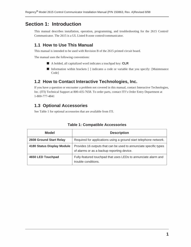
1.3 Optional AccessoriesSee Table 1 for optional accessories that are available from ITI.
Table 1: Compatible Accessories
Model Description
2608 Ground Start Relay Required for applications using a ground start telephone network.
4180 Status Display Module Provides 16 outputs that can be used to annunciate specific types
of alarms or as a backup reporting device.
4650 LED Touchpad Fully-featured touchpad that uses LEDs to annunciate alarm and
trouble conditions.
Regency® Model 2615 Control Communicator Installation Manual (P/N 150863, Rev. A)Revised 8/98
2
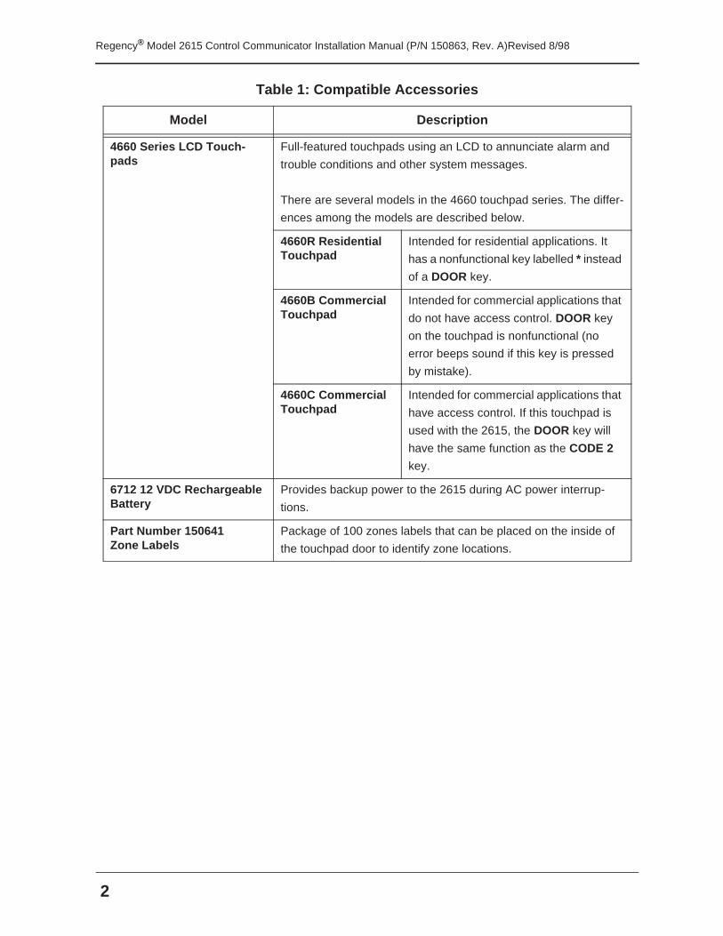
4660 Series LCD Touch-pads
Full-featured touchpads using an LCD to annunciate alarm and
trouble conditions and other system messages.
There are several models in the 4660 touchpad series. The differ-
ences among the models are described below.
4660R Residential Touchpad
Intended for residential applications. It
has a nonfunctional key labelled * instead
of a DOOR key.
4660B Commercial Touchpad
Intended for commercial applications that
do not have access control. DOOR key
on the touchpad is nonfunctional (no
error beeps sound if this key is pressed
by mistake).
4660C Commercial Touchpad
Intended for commercial applications that
have access control. If this touchpad is
used with the 2615, the DOOR key will
have the same function as the CODE 2
key.
6712 12 VDC Rechargeable Battery
Provides backup power to the 2615 during AC power interrup-
tions.
Part Number 150641Zone Labels
Package of 100 zones labels that can be placed on the inside of
the touchpad door to identify zone locations.
Table 1: Compatible Accessories
Model Description
3
Regency® Model 2615 Control Communicator Installation Manual (P/N 150863, Rev. A)Revised 8/98
Section 2: Specifications
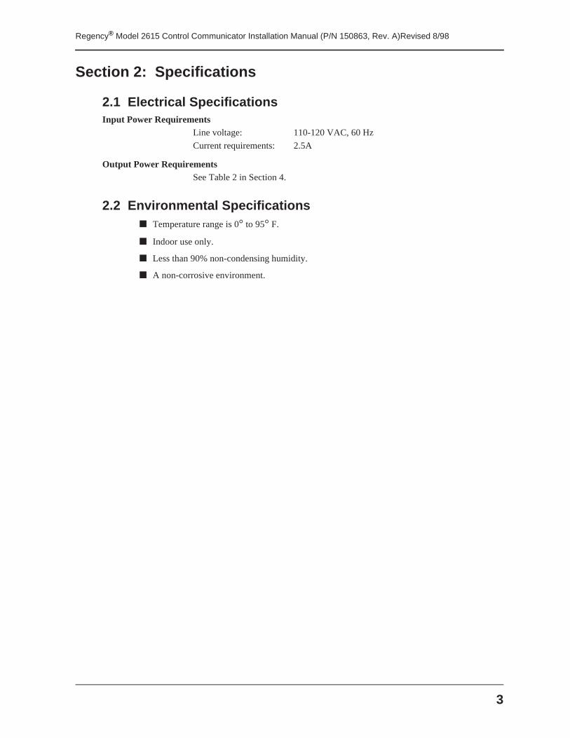
2.1 Electrical SpecificationsInput Power Requirements
Line voltage: 110-120 VAC, 60 Hz
Current requirements: 2.5A
Output Power RequirementsSee Table 2 in Section 4.
2.2 Environmental Specifications■ Temperature range is 0° to 95° F.
■ Indoor use only.
■ Less than 90% non-condensing humidity.
■ A non-corrosive environment.
Regency® Model 2615 Control Communicator Installation Manual (P/N 150863, Rev. A)Revised 8/98
4
Section 3: Agency Requirements
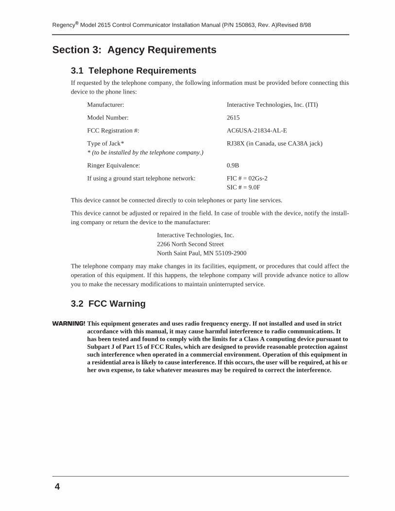
3.1 Telephone RequirementsIf requested by the telephone company, the following information must be provided before connecting this
device to the phone lines:
Manufacturer: Interactive Technologies, Inc. (ITI)
Model Number: 2615
FCC Registration #: AC6USA-21834-AL-E
Type of Jack* RJ38X (in Canada, use CA38A jack)
* (to be installed by the telephone company.)
Ringer Equivalence: 0.9B
If using a ground start telephone network: FIC # = 02Gs-2
SIC # = 9.0F
This device cannot be connected directly to coin telephones or party line services.
This device cannot be adjusted or repaired in the field. In case of trouble with the device, notify the install-
ing company or return the device to the manufacturer:
Interactive Technologies, Inc.
2266 North Second Street
North Saint Paul, MN 55109-2900
The telephone company may make changes in its facilities, equipment, or procedures that could affect the
operation of this equipment. If this happens, the telephone company will provide advance notice to allow
you to make the necessary modifications to maintain uninterrupted service.
3.2 FCC Warning
WARNING! This equipment generates and uses radio frequency energy. If not installed and used in strict accordance with this manual, it may cause harmful interference to radio communications. It has been tested and found to comply with the limits for a Class A computing device pursuant to Subpart J of Part 15 of FCC Rules, which are designed to provide reasonable protection against such interference when operated in a commercial environment. Operation of this equipment in a residential area is likely to cause interference. If this occurs, the user will be required, at his or her own expense, to take whatever measures may be required to correct the interference.
5
Regency® Model 2615 Control Communicator Installation Manual (P/N 150863, Rev. A)Revised 8/98
3.3 UL RequirementsUL Listed systems must meet the following requirements:
1. The Arm Lock Interior Key option must be enabled.
2. Do not select the following programmable options:
■ Silent Night Trouble option
■ Swinger Bypass option
■ Force Arm option
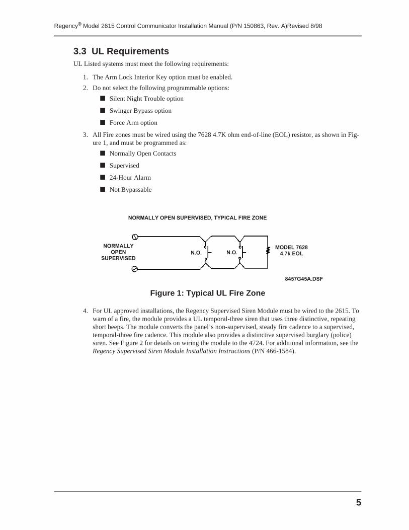
3. All Fire zones must be wired using the 7628 4.7K ohm end-of-line (EOL) resistor, as shown in Fig-ure 1, and must be programmed as:
■ Normally Open Contacts
■ Supervised
■ 24-Hour Alarm
■ Not Bypassable
Figure 1: Typical UL Fire Zone
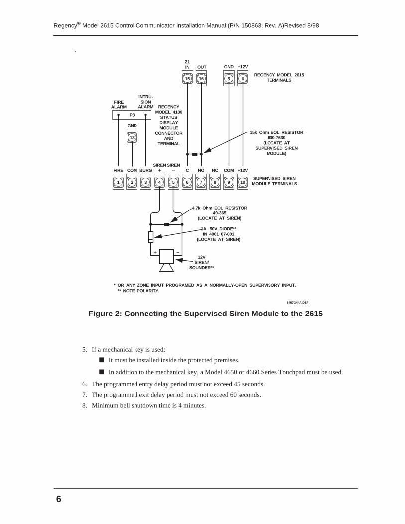
4. For UL approved installations, the Regency Supervised Siren Module must be wired to the 2615. To warn of a fire, the module provides a UL temporal-three siren that uses three distinctive, repeating short beeps. The module converts the panel’s non-supervised, steady fire cadence to a supervised, temporal-three fire cadence. This module also provides a distinctive supervised burglary (police) siren. See Figure 2 for details on wiring the module to the 4724. For additional information, see the Regency Supervised Siren Module Installation Instructions (P/N 466-1584).
N O R M A L L YO P E N
S U P E R V I S E D
M O D E L 7 6 2 84 . 7 k E O LN . O .N . O .
N O R M A L L Y O P E N S U P E R V I S E D , T Y P I C A L F I R E Z O N E
8 4 5 7 G 4 5 A . D S F
Regency® Model 2615 Control Communicator Installation Manual (P/N 150863, Rev. A)Revised 8/98
6
.
Figure 2: Connecting the Supervised Siren Module to the 2615
5. If a mechanical key is used:
■ It must be installed inside the protected premises.
■ In addition to the mechanical key, a Model 4650 or 4660 Series Touchpad must be used.
6. The programmed entry delay period must not exceed 45 seconds.
7. The programmed exit delay period must not exceed 60 seconds.
8. Minimum bell shutdown time is 4 minutes.
8457G44A.DSF
FIRE
4.7k Ohm EOL RESISTOR49-365
(LOCATE AT SIREN)
1
COM
2 4
BURG
3 5
NO
7
C
6
COM
9
NC
8
+12V
10
SIREN+
SIREN--
+ –12V
SIREN/SOUNDER**
Z1IN GNDOUT +12V
GND
13
P3
15k Ohm EOL RESISTOR600-7630
(LOCATE ATSUPERVISED SIREN
MODULE)
1A, 50V DIODE**IN 4001 07-001
(LOCATE AT SIREN)
FIREALARM
INTRU-SION
ALARM
REGENCY MODEL 2615 TERMINALS
REGENCYMODEL 4180
STATUSDISPLAYMODULE
CONNECTORAND
TERMINAL
SUPERVISED SIRENMODULE TERMINALS
* OR ANY ZONE INPUT PROGRAMED AS A NORMALLY-OPEN SUPERVISORY INPUT.
6515
** NOTE POLARITY.
16
7
Regency® Model 2615 Control Communicator Installation Manual (P/N 150863, Rev. A)Revised 8/98
Section 4: Control Panel Description and Installation
WARNING! To avoid the risk of electrical shock, do not apply power to the 2615 until you have carefully read all of these instructions.
This section describes how to install the control panel and accessories, including compatible add-on mod-
ules, such as smoke detectors and signaling devices. In all cases, refer to the compatible module’s installa-
tion manual for complete information.
4.1 Board Layout
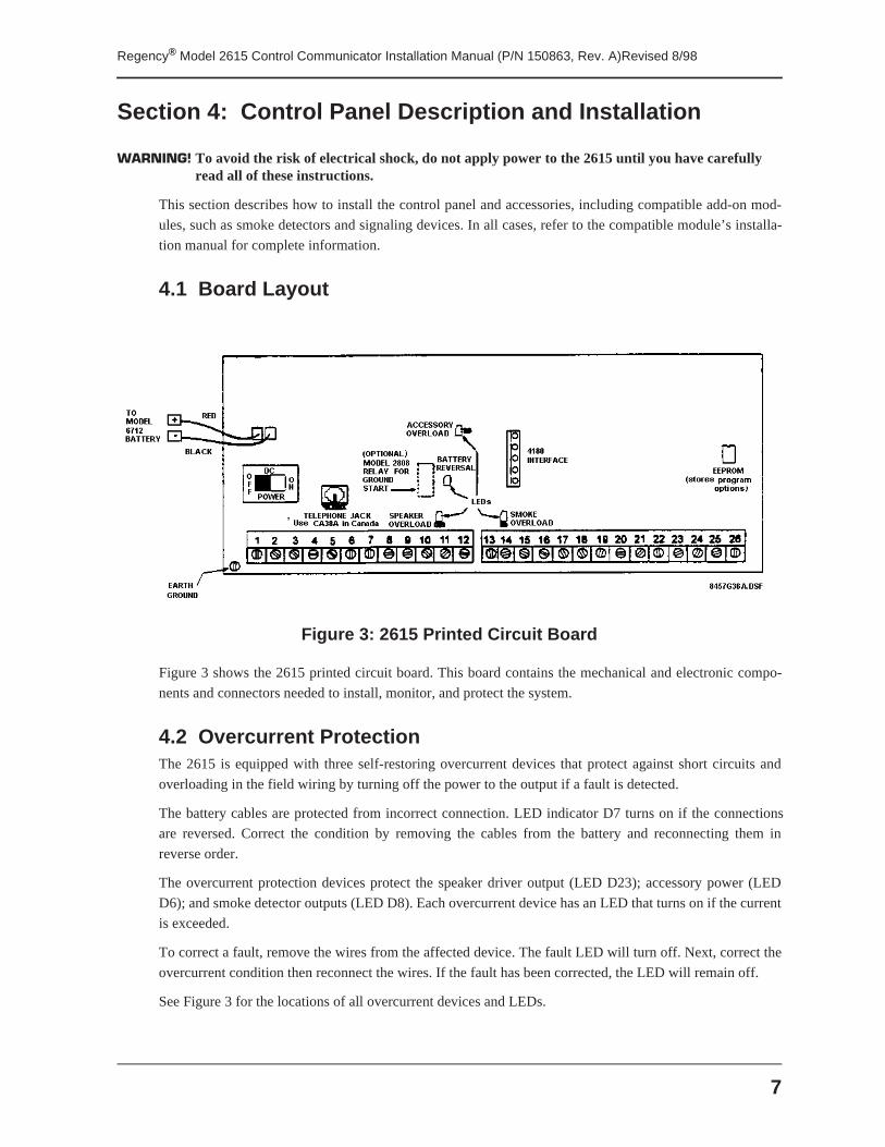
Figure 3: 2615 Printed Circuit Board
Figure 3 shows the 2615 printed circuit board. This board contains the mechanical and electronic compo-
nents and connectors needed to install, monitor, and protect the system.
4.2 Overcurrent ProtectionThe 2615 is equipped with three self-restoring overcurrent devices that protect against short circuits and
overloading in the field wiring by turning off the power to the output if a fault is detected.
The battery cables are protected from incorrect connection. LED indicator D7 turns on if the connections
are reversed. Correct the condition by removing the cables from the battery and reconnecting them in
reverse order.
The overcurrent protection devices protect the speaker driver output (LED D23); accessory power (LED
D6); and smoke detector outputs (LED D8). Each overcurrent device has an LED that turns on if the current
is exceeded.
To correct a fault, remove the wires from the affected device. The fault LED will turn off. Next, correct the
overcurrent condition then reconnect the wires. If the fault has been corrected, the LED will remain off.
See Figure 3 for the locations of all overcurrent devices and LEDs.
Regency® Model 2615 Control Communicator Installation Manual (P/N 150863, Rev. A)Revised 8/98
8
4.3 AC Power SwitchThe 2615 has an AC power switch. Make sure this switch is off when you are installing the system. See Fig-
ure 3 for the location of the power switch.
4.4 Mounting the 2615When selecting a location to mount the 2615, consider the following:
■ The acceptable temperature range is 0° to 95° F.
■ Panel must be accessible to “main drop” wiring runs.
■ Panel must be located well within the secured area, but must be accessible for testing and ser-vice.
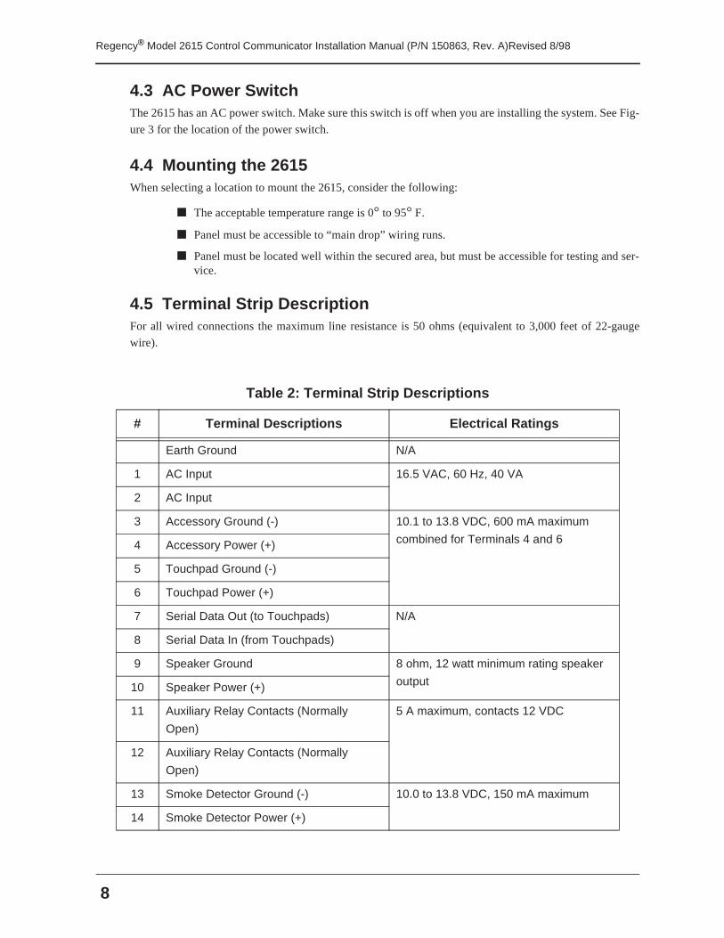
4.5 Terminal Strip DescriptionFor all wired connections the maximum line resistance is 50 ohms (equivalent to 3,000 feet of 22-gauge
wire).
Table 2: Terminal Strip Descriptions
# Terminal Descriptions Electrical Ratings
Earth Ground N/A
1 AC Input 16.5 VAC, 60 Hz, 40 VA
2 AC Input
3 Accessory Ground (-) 10.1 to 13.8 VDC, 600 mA maximum
combined for Terminals 4 and 64 Accessory Power (+)
5 Touchpad Ground (-)
6 Touchpad Power (+)
7 Serial Data Out (to Touchpads) N/A
8 Serial Data In (from Touchpads)
9 Speaker Ground 8 ohm, 12 watt minimum rating speaker
output10 Speaker Power (+)
11 Auxiliary Relay Contacts (Normally
Open)
5 A maximum, contacts 12 VDC
12 Auxiliary Relay Contacts (Normally
Open)
13 Smoke Detector Ground (-) 10.0 to 13.8 VDC, 150 mA maximum
14 Smoke Detector Power (+)
9
Regency® Model 2615 Control Communicator Installation Manual (P/N 150863, Rev. A)Revised 8/98
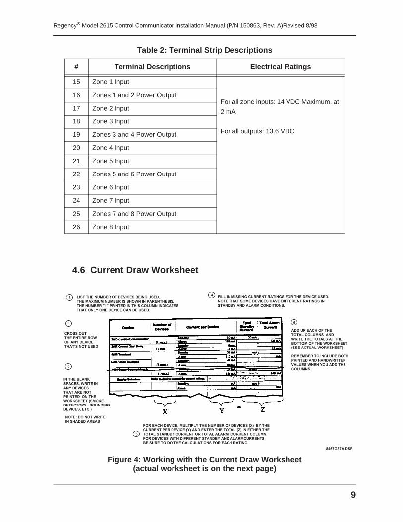
4.6 Current Draw Worksheet
Figure 4: Working with the Current Draw Worksheet(actual worksheet is on the next page)
15 Zone 1 Input
For all zone inputs: 14 VDC Maximum, at
2 mA
For all outputs: 13.6 VDC
16 Zones 1 and 2 Power Output
17 Zone 2 Input
18 Zone 3 Input
19 Zones 3 and 4 Power Output
20 Zone 4 Input
21 Zone 5 Input
22 Zones 5 and 6 Power Output
23 Zone 6 Input
24 Zone 7 Input
25 Zones 7 and 8 Power Output
26 Zone 8 Input
Table 2: Terminal Strip Descriptions
# Terminal Descriptions Electrical Ratings
1
2
3
5
4
C R O S S O U T T H E E N T I R E R O WO F A N Y D E V I C E T H A T ' S N O T U S E D
I N T H E B L A N K S P A C E S , W R I T E I N A N Y D E V I C E S T H A T A R E N O T P R I N T E D O N T H E W O R K S H E E T ( S M O K E D E T E C T O R S , S O U N D I N G D E V I C E S , E T C . )
F O R E A C H D E V I C E , M U L T I P L Y T H E N U M B E R O F D E V I C E S ( X ) B Y T H E C U R R E N T P E R D E V I C E ( Y ) A N D E N T E R T H E T O T A L ( Z ) I N E I T H E R T H E T O T A L S T A N D B Y C U R R E N T O R T O T A L A L A R M C U R R E N T C O L U M N . F O R D E V I C E S W I T H D I F F E R E N T S T A N D B Y A N D A L A R M C U R R E N T S , B E S U R E T O D O T H E C A L C U L A T I O N S F O R E A C H R A T I N G .
6
A D D U P E A C H O F T H E T O T A L C O L U M N S A N D W R I T E T H E T O T A L S A T T H E B O T T O M O F T H E W O R K S H E E T ( S E E A C T U A L W O R K S H E E T )
R E M E M B E R T O I N C L U D E B O T H P R I N T E D A N D H A N D W R I T T E N V A L U E S W H E N Y O U A D D T H E C O L U M N S .
N O T E : D O N O T W R I T E I N S H A D E D A R E A S
L I S T T H E N U M B E R O F D E V I C E S B E I N G U S E D .T H E M A X I M U M N U M B E R I S S H O W N I N P A R E N T H E S I S .T H E N U M B E R " 1 " P R I N T E D I N T H I S C O L U M N I N D I C A T E ST H A T O N L Y O N E D E V I C E C A N B E U S E D .
F I L L I N M I S S I N G C U R R E N T R A T I N G S F O R T H E D E V I C E U S E D .N O T E T H A T S O M E D E V I C E S H A V E D I F F E R E N T R A T I N G S I NS T A N D B Y A N D A L A R M C O N D I T I O N S .
8 4 5 7 G 3 7 A . D S F
Regency® Model 2615 Control Communicator Installation Manual (P/N 150863, Rev. A)Revised 8/98
10
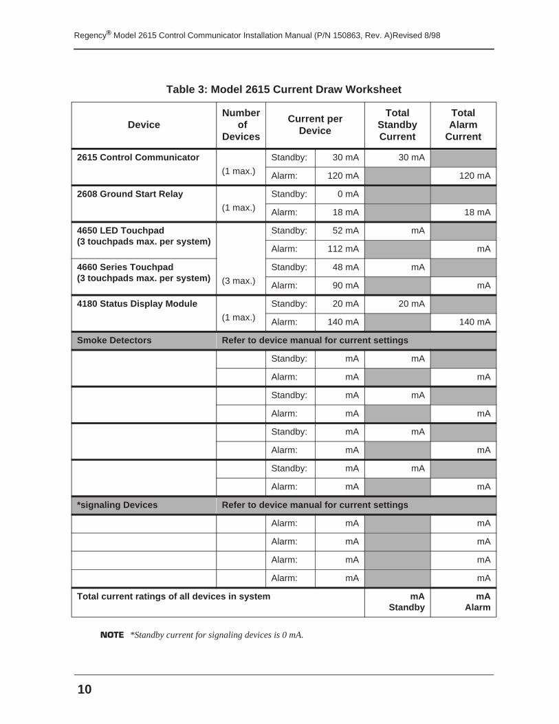
NOTE *Standby current for signaling devices is 0 mA.
Table 3: Model 2615 Current Draw Worksheet
DeviceNumber
of Devices
Current per Device
Total Standby Current
Total Alarm
Current
2615 Control Communicator
(1 max.)
Standby: 30 mA 30 mA
Alarm: 120 mA 120 mA
2608 Ground Start Relay
(1 max.)
Standby: 0 mA
Alarm: 18 mA 18 mA
4650 LED Touchpad(3 touchpads max. per system)
Standby: 52 mA mA
Alarm: 112 mA mA
4660 Series Touchpad(3 touchpads max. per system) (3 max.)
Standby: 48 mA mA
Alarm: 90 mA mA
4180 Status Display Module
(1 max.)
Standby: 20 mA 20 mA
Alarm: 140 mA 140 mA
Smoke Detectors Refer to device manual for current settings
Standby: mA mA
Alarm: mA mA
Standby: mA mA
Alarm: mA mA
Standby: mA mA
Alarm: mA mA
Standby: mA mA
Alarm: mA mA
*signaling Devices Refer to device manual for current settings
Alarm: mA mA
Alarm: mA mA
Alarm: mA mA
Alarm: mA mA
Total current ratings of all devices in system mAStandby
mAAlarm
11
Regency® Model 2615 Control Communicator Installation Manual (P/N 150863, Rev. A)Revised 8/98
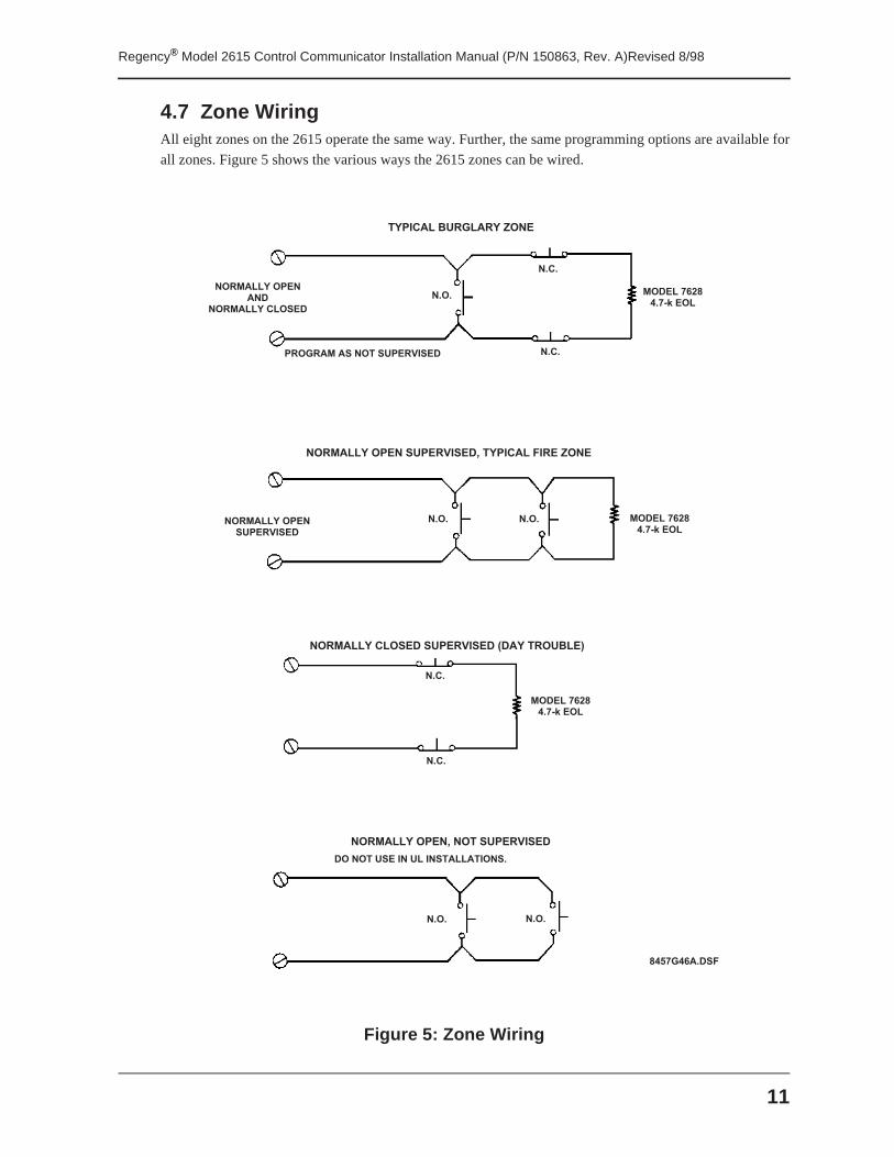
4.7 Zone WiringAll eight zones on the 2615 operate the same way. Further, the same programming options are available for
all zones. Figure 5 shows the various ways the 2615 zones can be wired.
Figure 5: Zone Wiring
8 4 5 7 G 4 6 A . D S F
N O R M A L L Y O P E NA N D
N O R M A L L Y C L O S E D
T Y P I C A L B U R G L A R Y Z O N E
N . O .
N . C .
N . C .
M O D E L 7 6 2 84 . 7 - k E O L
P R O G R A M A S N O T S U P E R V I S E D
M O D E L 7 6 2 84 . 7 - k E O L
M O D E L 7 6 2 84 . 7 - k E O L
N O R M A L L Y O P E NS U P E R V I S E D
N . O . N . O .
N O R M A L L Y O P E N S U P E R V I S E D , T Y P I C A L F I R E Z O N E
N O R M A L L Y C L O S E D S U P E R V I S E D ( D A Y T R O U B L E )
N O R M A L L Y O P E N , N O T S U P E R V I S E D
D O N O T U S E I N U L I N S T A L L A T I O N S .
N . O .
N . C .
N . O .
N . C .
Regency® Model 2615 Control Communicator Installation Manual (P/N 150863, Rev. A)Revised 8/98
12
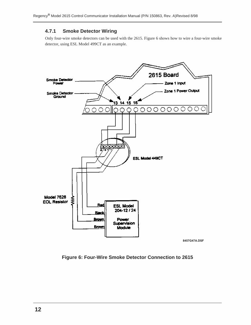
4.7.1 Smoke Detector WiringOnly four-wire smoke detectors can be used with the 2615. Figure 6 shows how to wire a four-wire smoke
detector, using ESL Model 499CT as an example.
Figure 6: Four-Wire Smoke Detector Connection to 2615
8 4 5 7 G 4 7 A . D S F
13
Regency® Model 2615 Control Communicator Installation Manual (P/N 150863, Rev. A)Revised 8/98
4.8 Signaling Device Wiring
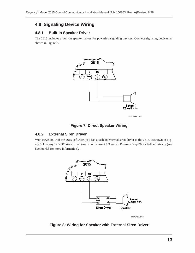
4.8.1 Built-In Speaker DriverThe 2615 includes a built-in speaker driver for powering signaling devices. Connect signaling devices as
shown in Figure 7.
Figure 7: Direct Speaker Wiring
4.8.2 External Siren DriverWith Revision D of the 2615 software, you can attach an external siren driver to the 2615, as shown in Fig-
ure 8. Use any 12 VDC siren driver (maximum current 1.3 amps). Program Step 26 for bell and steady (see
Section 6.3 for more information).
Figure 8: Wiring for Speaker with External Siren Driver
8 4 5 7 G 4 8 A . D S F
8 4 5 7 G 4 9 A . D S F
Regency® Model 2615 Control Communicator Installation Manual (P/N 150863, Rev. A)Revised 8/98
14
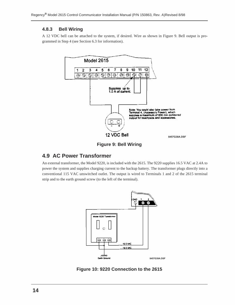
4.8.3 Bell WiringA 12 VDC bell can be attached to the system, if desired. Wire as shown in Figure 9. Bell output is pro-
grammed in Step 4 (see Section 6.3 for information).
Figure 9: Bell Wiring
4.9 AC Power TransformerAn external transformer, the Model 9220, is included with the 2615. The 9220 supplies 16.5 VAC at 2.4A to
power the system and supplies charging current to the backup battery. The transformer plugs directly into a
conventional 115 VAC unswitched outlet. The output is wired to Terminals 1 and 2 of the 2615 terminal
strip and to the earth ground screw (to the left of the terminal).
Figure 10: 9220 Connection to the 2615
8 4 5 7 G 3 8 A . D S F
8 4 5 7 G 3 9 A . D S F
15
Regency® Model 2615 Control Communicator Installation Manual (P/N 150863, Rev. A)Revised 8/98
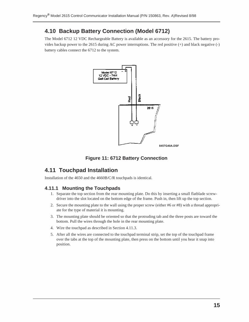
4.10 Backup Battery Connection (Model 6712)The Model 6712 12 VDC Rechargeable Battery is available as an accessory for the 2615. The battery pro-
vides backup power to the 2615 during AC power interruptions. The red positive (+) and black negative (-)
battery cables connect the 6712 to the system.
Figure 11: 6712 Battery Connection
4.11 Touchpad InstallationInstallation of the 4650 and the 4660B/C/R touchpads is identical.
4.11.1 Mounting the Touchpads1. Separate the top section from the rear mounting plate. Do this by inserting a small flatblade screw-
driver into the slot located on the bottom edge of the frame. Push in, then lift up the top section.
2. Secure the mounting plate to the wall using the proper screw (either #6 or #8) with a thread appropri-ate for the type of material it is mounting.
3. The mounting plate should be oriented so that the protruding tab and the three posts are toward the bottom. Pull the wires through the hole in the rear mounting plate.
4. Wire the touchpad as described in Section 4.11.3.
5. After all the wires are connected to the touchpad terminal strip, set the top of the touchpad frame over the tabs at the top of the mounting plate, then press on the bottom until you hear it snap into position.
8 4 5 7 G 4 0 A . D S F
Regency® Model 2615 Control Communicator Installation Manual (P/N 150863, Rev. A)Revised 8/98
16
4.11.2 Touchpad Specifications■ Three touchpads maximum per system.
■ All touchpads require four wires to operate.
■ The four-conductor cable can be up to 1,000 feet long.
■ Minimum wire gauge is 22 AWG for runs under 500 feet.
■ Minimum wire gauge is 18 AWG for runs between 500 to 1000 feet.
■ Active current draw is 120 mA.
■ Active allowed voltage drop is 2V.
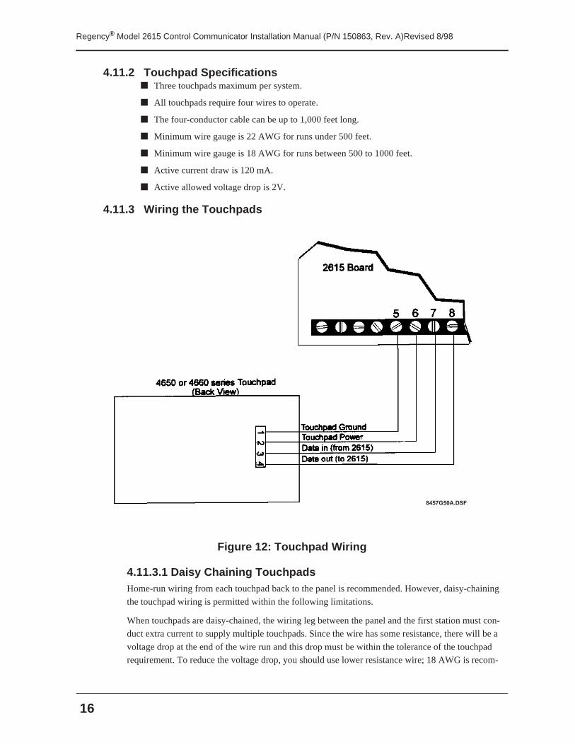
4.11.3 Wiring the Touchpads
Figure 12: Touchpad Wiring
4.11.3.1 Daisy Chaining TouchpadsHome-run wiring from each touchpad back to the panel is recommended. However, daisy-chaining
the touchpad wiring is permitted within the following limitations.
When touchpads are daisy-chained, the wiring leg between the panel and the first station must con-
duct extra current to supply multiple touchpads. Since the wire has some resistance, there will be a
voltage drop at the end of the wire run and this drop must be within the tolerance of the touchpad
requirement. To reduce the voltage drop, you should use lower resistance wire; 18 AWG is recom-
8 4 5 7 G 5 0 A . D S F
17
Regency® Model 2615 Control Communicator Installation Manual (P/N 150863, Rev. A)Revised 8/98
mended.
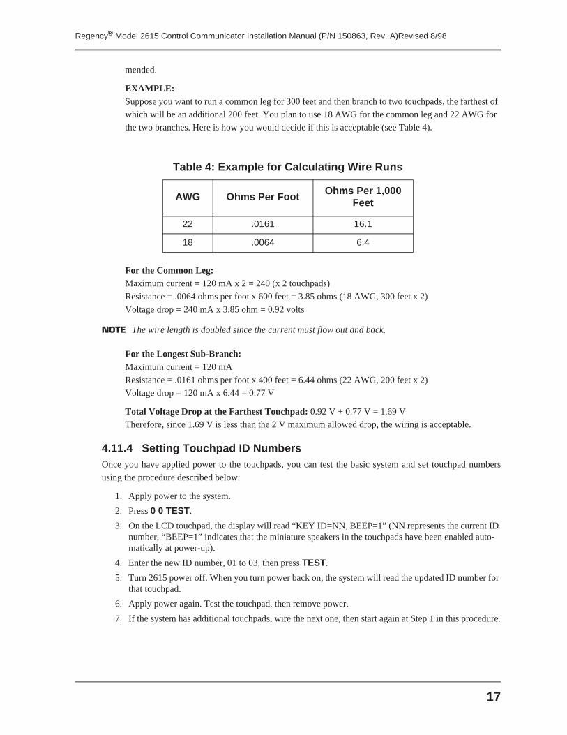
EXAMPLE:Suppose you want to run a common leg for 300 feet and then branch to two touchpads, the farthest of
which will be an additional 200 feet. You plan to use 18 AWG for the common leg and 22 AWG for
the two branches. Here is how you would decide if this is acceptable (see Table 4).
For the Common Leg:Maximum current = 120 mA x 2 = 240 (x 2 touchpads)
Resistance = .0064 ohms per foot x 600 feet = 3.85 ohms (18 AWG, 300 feet x 2)
Voltage drop = 240 mA x 3.85 ohm = 0.92 volts
NOTE The wire length is doubled since the current must flow out and back.
For the Longest Sub-Branch:Maximum current = 120 mA
Resistance = .0161 ohms per foot x 400 feet = 6.44 ohms (22 AWG, 200 feet x 2)
Voltage drop = 120 mA x 6.44 = 0.77 V
Total Voltage Drop at the Farthest Touchpad: 0.92 V + 0.77 V = 1.69 V
Therefore, since 1.69 V is less than the 2 V maximum allowed drop, the wiring is acceptable.
4.11.4 Setting Touchpad ID NumbersOnce you have applied power to the touchpads, you can test the basic system and set touchpad numbers
using the procedure described below:
1. Apply power to the system.
2. Press 0 0 TEST.
3. On the LCD touchpad, the display will read “KEY ID=NN, BEEP=1” (NN represents the current ID number, “BEEP=1” indicates that the miniature speakers in the touchpads have been enabled auto-matically at power-up).
4. Enter the new ID number, 01 to 03, then press TEST.
5. Turn 2615 power off. When you turn power back on, the system will read the updated ID number for that touchpad.
6. Apply power again. Test the touchpad, then remove power.
7. If the system has additional touchpads, wire the next one, then start again at Step 1 in this procedure.
Table 4: Example for Calculating Wire Runs
AWG Ohms Per Foot Ohms Per 1,000 Feet
22 .0161 16.1
18 .0064 6.4
Regency® Model 2615 Control Communicator Installation Manual (P/N 150863, Rev. A)Revised 8/98
18
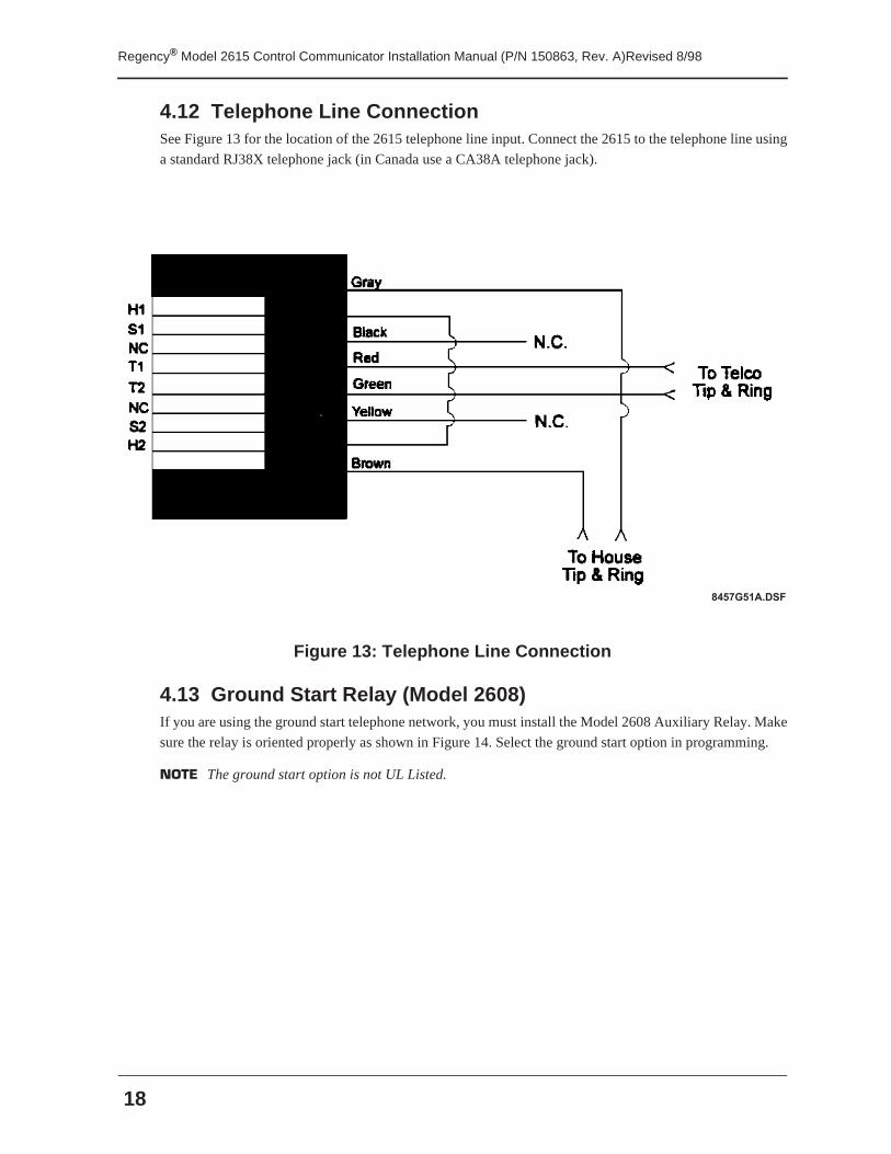
4.12 Telephone Line ConnectionSee Figure 13 for the location of the 2615 telephone line input. Connect the 2615 to the telephone line using
a standard RJ38X telephone jack (in Canada use a CA38A telephone jack).
Figure 13: Telephone Line Connection
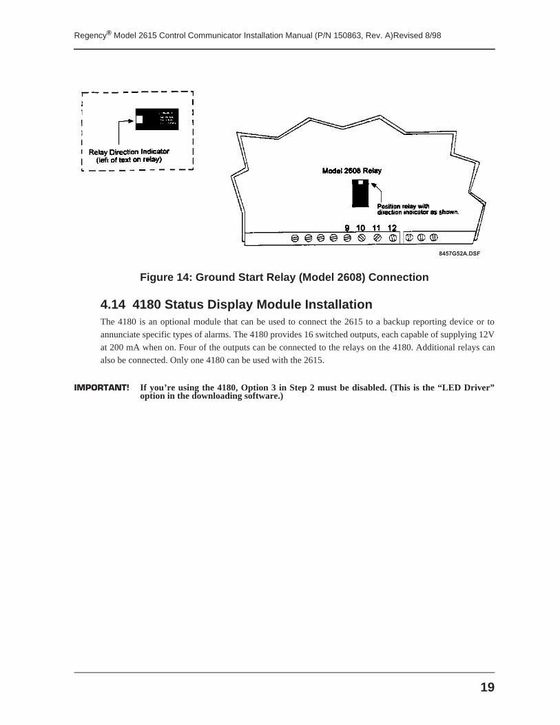
4.13 Ground Start Relay (Model 2608)If you are using the ground start telephone network, you must install the Model 2608 Auxiliary Relay. Make
sure the relay is oriented properly as shown in Figure 14. Select the ground start option in programming.
NOTE The ground start option is not UL Listed.
8 4 5 7 G 5 1 A . D S F
19
Regency® Model 2615 Control Communicator Installation Manual (P/N 150863, Rev. A)Revised 8/98
Figure 14: Ground Start Relay (Model 2608) Connection
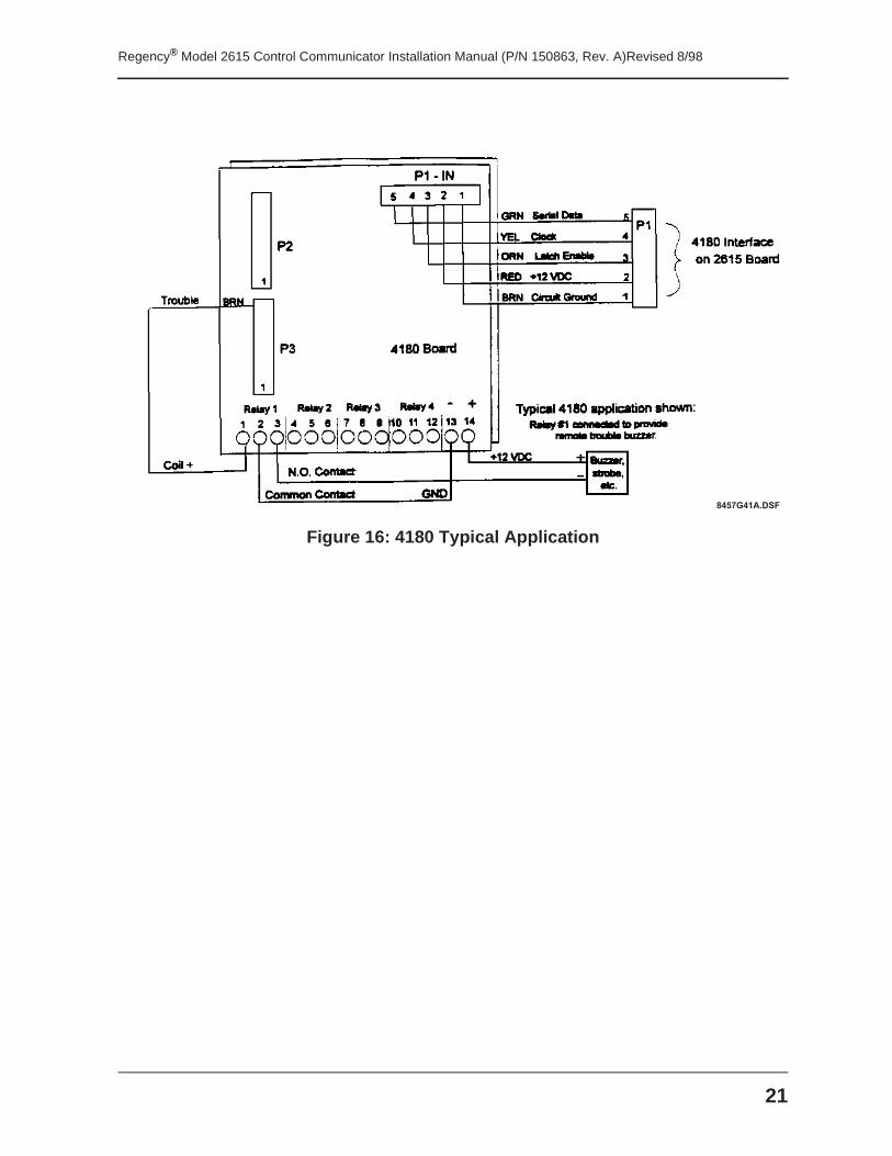
4.14 4180 Status Display Module InstallationThe 4180 is an optional module that can be used to connect the 2615 to a backup reporting device or to
annunciate specific types of alarms. The 4180 provides 16 switched outputs, each capable of supplying 12V
at 200 mA when on. Four of the outputs can be connected to the relays on the 4180. Additional relays can
also be connected. Only one 4180 can be used with the 2615.
IMPORTANT! If you’re using the 4180, Option 3 in Step 2 must be disabled. (This is the “LED Driver”option in the downloading software.)
8 4 5 7 G 5 2 A . D S F
Regency® Model 2615 Control Communicator Installation Manual (P/N 150863, Rev. A)Revised 8/98
20
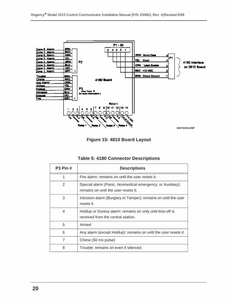
Figure 15: 4810 Board Layout
Table 5: 4180 Connector Descriptions
P3 Pin # Descriptions
1 Fire alarm: remains on until the user resets it.
2 Special alarm (Panic, Nonmedical emergency, or Auxiliary):
remains on until the user resets it.
3 Intrusion alarm (Burglary or Tamper): remains on until the user
resets it.
4 Holdup or Duress alarm: remains on only until kiss-off is
received from the central station.
5 Armed
6 Any alarm (except Holdup): remains on until the user resets it.
7 Chime (50 ms pulse)
8 Trouble: remains on even if silenced.
8 4 5 7 G 5 3 A . D S F
21
Regency® Model 2615 Control Communicator Installation Manual (P/N 150863, Rev. A)Revised 8/98
Figure 16: 4180 Typical Application
8 4 5 7 G 4 1 A . D S F

Regency® Model 2615 Control Communicator Installation Manual (P/N 150863, Rev. A)Revised 8/98
22
Section 5: Basic System Operations
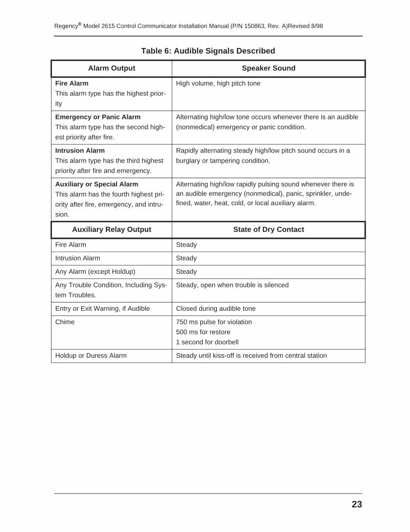
5.1 Audible Signals
Table 6: Audible Signals Described
Condition Touchpad Speaker Sound
Entry warning Three ascending tones repeated once per second
Exit warning A high to low two-tone sound repeated once per second
Time-out of program mode warning A high to low two-tone sound repeated once per second for 60
seconds
Cross Pre-alarm A constant two-tone alert that sounds only if the Cross Alarm
Zones 3 & 4 and Audible Pre-Alarm options were selected in
programming. The warning tone will sound for the pro-
grammed amount of time in only one of the zones (either Zone
3 or 4) is tripped. If the corresponding zone is tripped during
the programmed time period, the tone will switch to an alarm
sound. The cross pre-alarm can be reset and silenced by
entering a valid user code.
Alarm A sequence of two alternating tones followed by a pause that
repeats every four seconds.
Zone trouble One beep every four seconds.
Chime zone opened A low to high two-tone alert that sounds one time when a
Chime Zone is opened (if the Chime feature has been
enabled).
Chime zone closed A single high to low two-tone alert that sounds once each time
a Chime Zone is closed (if the Chime feature has been
enabled).
Door bell A four-tone sound similar to a door bell.
Touchpad keystroke Single short beep for a normal (correct) keystroke. A longer
beep indicates an incorrect keystroke.
Zone display activated
(except silent alarms)
A single beep
23
Regency® Model 2615 Control Communicator Installation Manual (P/N 150863, Rev. A)Revised 8/98
Alarm Output Speaker Sound
Fire Alarm
This alarm type has the highest prior-
ity
High volume, high pitch tone
Emergency or Panic Alarm
This alarm type has the second high-
est priority after fire.
Alternating high/low tone occurs whenever there is an audible
(nonmedical) emergency or panic condition.
Intrusion Alarm
This alarm type has the third highest
priority after fire and emergency.
Rapidly alternating steady high/low pitch sound occurs in a
burglary or tampering condition.
Auxiliary or Special Alarm
This alarm has the fourth highest pri-
ority after fire, emergency, and intru-
sion.
Alternating high/low rapidly pulsing sound whenever there is an audible emergency (nonmedical), panic, sprinkler, unde-fined, water, heat, cold, or local auxiliary alarm.
Auxiliary Relay Output State of Dry Contact
Fire Alarm Steady
Intrusion Alarm Steady
Any Alarm (except Holdup) Steady
Any Trouble Condition, Including Sys-
tem Troubles.
Steady, open when trouble is silenced
Entry or Exit Warning, if Audible Closed during audible tone
Chime 750 ms pulse for violation
500 ms for restore
1 second for doorbell
Holdup or Duress Alarm Steady until kiss-off is received from central station
Table 6: Audible Signals Described
Regency® Model 2615 Control Communicator Installation Manual (P/N 150863, Rev. A)Revised 8/98
24
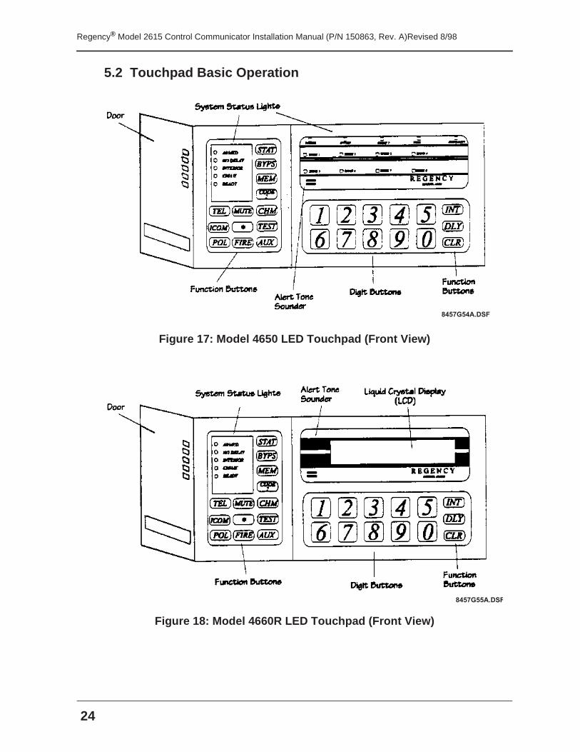
5.2 Touchpad Basic Operation
Figure 17: Model 4650 LED Touchpad (Front View)
Figure 18: Model 4660R LED Touchpad (Front View)
8 4 5 7 G 5 4 A . D S F
8 4 5 7 G 5 5 A . D S F
25
Regency® Model 2615 Control Communicator Installation Manual (P/N 150863, Rev. A)Revised 8/98
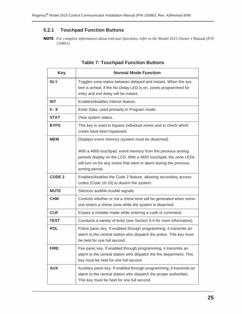
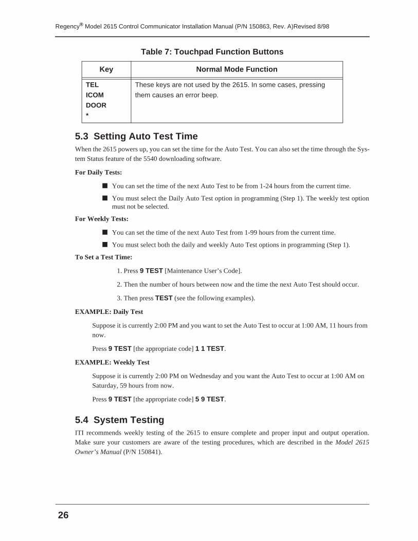
5.2.1 Touchpad Function Buttons
NOTE For complete information about end-user functions, refer to the Model 2615 Owner’s Manual (P/N150841).
Table 7: Touchpad Function Buttons
Key Normal Mode Function
DLY Toggles zone status between delayed and instant. When the sys-
tem is armed, if the No Delay LED is on, zones programmed for
entry and exit delay will be instant.
INT Enables/disables Interior feature.
0 - 9 Enter Data; used primarily in Program mode.
STAT View system status.
BYPS This key is used to bypass individual zones and to check which
zones have been bypassed.
MEM Displays event memory (system must be disarmed).
With a 4660 touchpad, event memory from the previous arming
periods display on the LCD. With a 4650 touchpad, the zone LEDs
will turn on for any zones that were in alarm during the previous
arming period.
CODE 2 Enables/disables the Code 2 feature, allowing secondary access
codes (Code 10-19) to disarm the system.
MUTE Silences audible trouble signals.
CHM Controls whether or not a chime tone will be generated when some-
one enters a chime zone while the system is disarmed.
CLR Erases a mistake made while entering a code or command.
TEST Conducts a variety of tests (see Section 5.4 for more information).
POL Police panic key. If enabled through programming, it transmits an
alarm to the central station who dispatch the police. This key must
be held for one full second.
FIRE Fire panic key. If enabled through programming, it transmits an
alarm to the central station who dispatch the fire department. This
key must be held for one full second.
AUX Auxiliary panic key. If enabled through programming, it transmits an
alarm to the central station who dispatch the proper authorities.
This key must be held for one full second.
Regency® Model 2615 Control Communicator Installation Manual (P/N 150863, Rev. A)Revised 8/98
26
5.3 Setting Auto Test TimeWhen the 2615 powers up, you can set the time for the Auto Test. You can also set the time through the Sys-
tem Status feature of the 5540 downloading software.
For Daily Tests:
■ You can set the time of the next Auto Test to be from 1-24 hours from the current time.
■ You must select the Daily Auto Test option in programming (Step 1). The weekly test optionmust not be selected.
For Weekly Tests:
■ You can set the time of the next Auto Test from 1-99 hours from the current time.
■ You must select both the daily and weekly Auto Test options in programming (Step 1).
To Set a Test Time:
1. Press 9 TEST [Maintenance User’s Code].
2. Then the number of hours between now and the time the next Auto Test should occur.
3. Then press TEST (see the following examples).
EXAMPLE: Daily Test
Suppose it is currently 2:00 PM and you want to set the Auto Test to occur at 1:00 AM, 11 hours from
now.
Press 9 TEST [the appropriate code] 1 1 TEST.
EXAMPLE: Weekly Test
Suppose it is currently 2:00 PM on Wednesday and you want the Auto Test to occur at 1:00 AM on
Saturday, 59 hours from now.
Press 9 TEST [the appropriate code] 5 9 TEST.
5.4 System TestingITI recommends weekly testing of the 2615 to ensure complete and proper input and output operation.
Make sure your customers are aware of the testing procedures, which are described in the Model 2615
Owner’s Manual (P/N 150841).
TEL
ICOM
DOOR
*
These keys are not used by the 2615. In some cases, pressing
them causes an error beep.
Table 7: Touchpad Function Buttons
Key Normal Mode Function
27
Regency® Model 2615 Control Communicator Installation Manual (P/N 150863, Rev. A)Revised 8/98
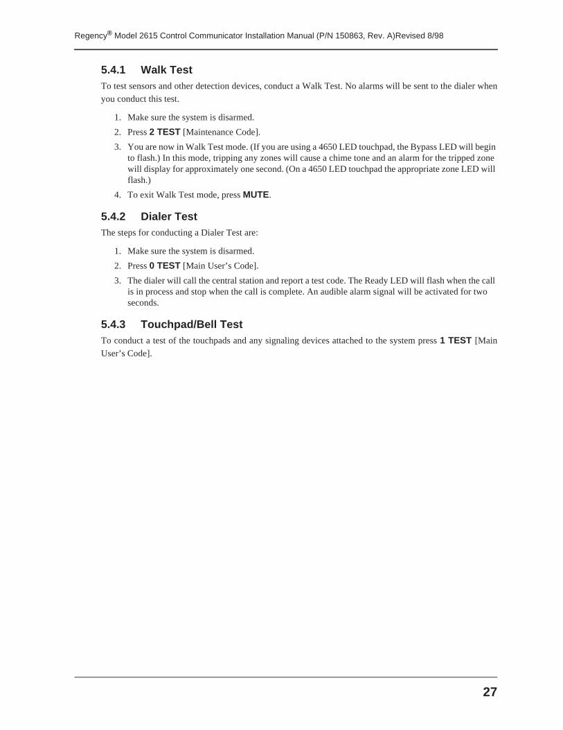
5.4.1 Walk TestTo test sensors and other detection devices, conduct a Walk Test. No alarms will be sent to the dialer when
you conduct this test.
1. Make sure the system is disarmed.
2. Press 2 TEST [Maintenance Code].
3. You are now in Walk Test mode. (If you are using a 4650 LED touchpad, the Bypass LED will begin to flash.) In this mode, tripping any zones will cause a chime tone and an alarm for the tripped zone will display for approximately one second. (On a 4650 LED touchpad the appropriate zone LED will flash.)
4. To exit Walk Test mode, press MUTE.
5.4.2 Dialer TestThe steps for conducting a Dialer Test are:
1. Make sure the system is disarmed.
2. Press 0 TEST [Main User’s Code].
3. The dialer will call the central station and report a test code. The Ready LED will flash when the call is in process and stop when the call is complete. An audible alarm signal will be activated for two seconds.
5.4.3 Touchpad/Bell TestTo conduct a test of the touchpads and any signaling devices attached to the system press 1 TEST [Main
User’s Code].
Regency® Model 2615 Control Communicator Installation Manual (P/N 150863, Rev. A)Revised 8/98
28
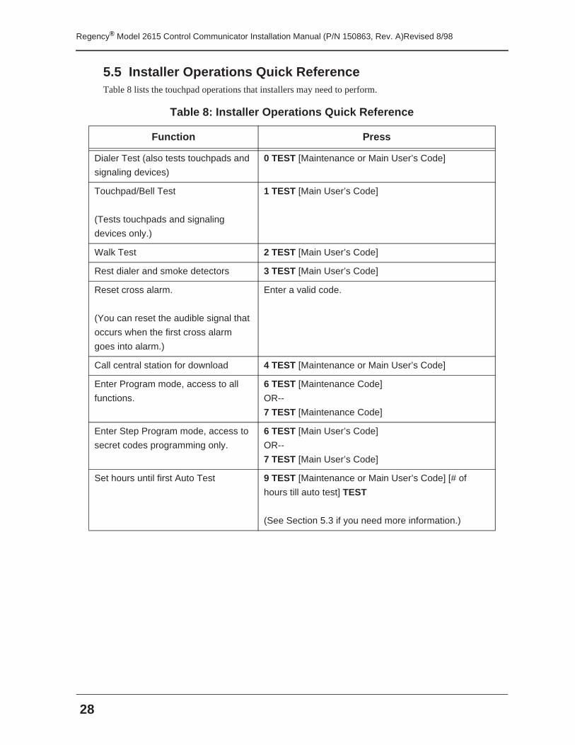
5.5 Installer Operations Quick ReferenceTable 8 lists the touchpad operations that installers may need to perform.
Table 8: Installer Operations Quick Reference
Function Press
Dialer Test (also tests touchpads and
signaling devices)
0 TEST [Maintenance or Main User’s Code]
Touchpad/Bell Test
(Tests touchpads and signaling
devices only.)
1 TEST [Main User’s Code]
Walk Test 2 TEST [Main User’s Code]
Rest dialer and smoke detectors 3 TEST [Main User’s Code]
Reset cross alarm.
(You can reset the audible signal that
occurs when the first cross alarm
goes into alarm.)
Enter a valid code.
Call central station for download 4 TEST [Maintenance or Main User’s Code]
Enter Program mode, access to all
functions.
6 TEST [Maintenance Code]
OR--
7 TEST [Maintenance Code]
Enter Step Program mode, access to
secret codes programming only.
6 TEST [Main User’s Code]
OR--
7 TEST [Main User’s Code]
Set hours until first Auto Test 9 TEST [Maintenance or Main User’s Code] [# of
hours till auto test] TEST
(See Section 5.3 if you need more information.)
29
Regency® Model 2615 Control Communicator Installation Manual (P/N 150863, Rev. A)Revised 8/98
Section 6: ProgrammingThe 2615 can be programmed remotely using the 5540 downloading software (see Section 6.1) or at the
customer site using the touchpad (see Section 6.2). All programmable options are described in Section 6.3.
6.1 DownloadingThe Model 5540 Downloading Software can be used to program the 2615 from a remote site. Note that
Revision 3.8 or later of the 5540 is required.
The downloading software is organized into menus. As you move through the software menus, the screens
tell you how to select options.
The 2615 programming options themselves are described in detail in Section 6.3 of this manual. Section 6.3
also tells you on which software menu the options appear. Refer to the 5540 Installation and Operation
Manual (P/N 150639) for complete information about the 5540 software.
6.2 Step ProgrammingStep programming allows you to program 2615 options directly from the touchpad. The subsections below
describe step programming touchpad operations. Section 6.3 describes all programmable options in detail
and explains how to make selections.
6.2.1 Touchpad OperationSome function buttons and LEDs have a different use in Program mode than they do in normal operations.
Keys and Program Mode Use:
STAT View the step you are currently programming.
MEM View the sub-step you are currently programming.
BYPS Use a SHIFT key to allow you to, for example, enter numbers larger than
9.
MUTE Exit Program mode.
LEDs and the Options Being Programmed:
ARMED Systems options and Code 0.
CODE 2 User access code 1 - 19 (4650 touchpad only).
AUXILIARY Zone types (including panic keys) (4650 touchpad only).
INTERIOR Zone input options.
NO DELAY Timer options (entry/exit delays, etc.).
READY Dialer options.
ZONE With a 4650 LED touchpad, Zone LEDs will turn on to indicate that
an option has been selected for some sub-steps.
Regency® Model 2615 Control Communicator Installation Manual (P/N 150863, Rev. A)Revised 8/98
30
6.2.1.1 Entering Program ModeWhen the system is ready (the Ready LED is lit), press 6 TEST [code]. If you enter Program mode
using the Maintenance Code, you will be at Step 1. If you use the main user code, you will be at Step
8 (access code programming).
6.2.1.2 How to Tell Which Step You Are Currently OnPress STAT to see what step you are on.
Press TEST to return to programming for that step.
Press MEM to see what sub-step you are on.
Press TEST to return to programming for that sub-step.
6.2.1.3 Moving to a Different StepPress TEST as many times as necessary until you reach the step you want to program. If you are
using an LED touchpad where the step number does not display, you can keep track of which step or
sub-step you are on by counting the number of times you press TEST.
If you are using the Maintenance Code, you can use a shortcut method, if desired. Press STAT [the
number of the step you want to program] and TEST.
EXAMPLE: Jumping to a Step (Maintenance Code Only)
To move to Step 6: Press STAT 6 TEST.
6.2.1.4 Moving to a Different Sub-StepOnce you are on the step you want to be on, you can use the MEM key to move to a different sub-step.
For example, to move to Sub-Step 6, press MEM 6 TEST.
6.2.1.5 Entering DataAll programmable data is numeric. (Section 6.3 tells you what are acceptable values for each step).
After you enter the new data, press TEST to accept the changes.
6.2.1.6 Correcting ErrorsIf you make a mistake, and have not yet entered the TEST key to accept the changes, press CLR to
erase the data.
If you need to change information that has already been entered, return to the step (as described in
Section 6.2.1.3) and enter the correct information.
6.2.1.7 Exiting Program ModePress MUTE to exit Program mode at any time.
31
Regency® Model 2615 Control Communicator Installation Manual (P/N 150863, Rev. A)Revised 8/98
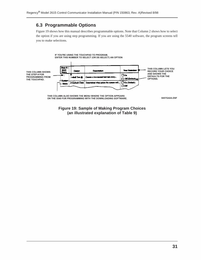
6.3 Programmable OptionsFigure 19 shows how this manual describes programmable options. Note that Column 2 shows how to select
the option if you are using step programming. If you are using the 5540 software, the program screens tell
you to make selections.
Figure 19: Sample of Making Program Choices(an illustrated explanation of Table 9)
8 4 5 7 G 4 2 A . D S F
I F Y O U ' R E U S I N G T H E T O U C H P A D T O P R O G R A M ,E N T E R T H I S N U M B E R T O S E L E C T ( O R D E - S E L E C T ) A N O P T I O N
T H I S C O L U M N S H O W ST H E S T E P # F O R P R O G R A M M I N G F R O M T H E T O U C H P A D .
T H I S C O L U M N A L S O S H O W S T H E M E N U W H E R E T H E O P T I O N A P P E A R SO N T H E 5 5 4 0 F O R P R O G R A M M I N G W I T H T H E D O W N L O A D I N G S O F T W A R E .
T H I S C O L U M N L E T S Y O U R E C O R D Y O U R C H O I C EA N D S H O W S T H ED E F A U L T S F O R T H E O P T I O N S .
Regency® Model 2615 Control Communicator Installation Manual (P/N 150863, Rev. A)Revised 8/98
32
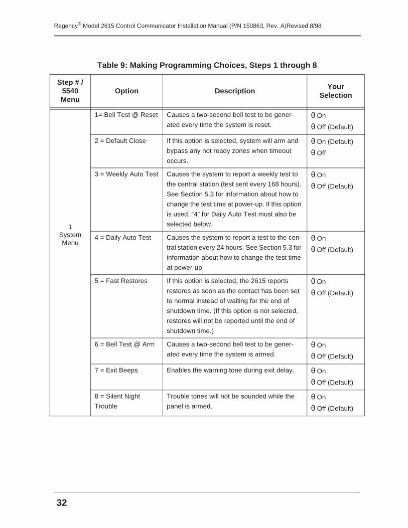
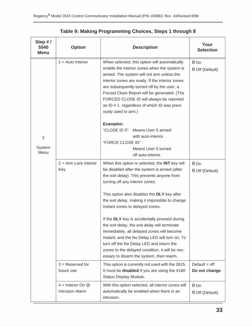
Table 9: Making Programming Choices, Steps 1 through 8
Step # / 5540 Menu
Option Description Your Selection
1System Menu
1= Bell Test @ Reset Causes a two-second bell test to be gener-
ated every time the system is reset.θ On
θ Off (Default)
2 = Default Close If this option is selected, system will arm and
bypass any not ready zones when timeout
occurs.
θ On (Default)
θ Off
3 = Weekly Auto Test Causes the system to report a weekly test to
the central station (test sent every 168 hours).
See Section 5.3 for information about how to
change the test time at power-up. If this option
is used, “4” for Daily Auto Test must also be
selected below.
θ On
θ Off (Default)
4 = Daily Auto Test Causes the system to report a test to the cen-
tral station every 24 hours. See Section 5.3 for
information about how to change the test time
at power-up.
θ On
θ Off (Default)
5 = Fast Restores If this option is selected, the 2615 reports
restores as soon as the contact has been set
to normal instead of waiting for the end of
shutdown time. (If this option is not selected,
restores will not be reported until the end of
shutdown time.)
θ On
θ Off (Default)
6 = Bell Test @ Arm Causes a two-second bell test to be gener-
ated every time the system is armed.θ On
θ Off (Default)
7 = Exit Beeps Enables the warning tone during exit delay. θ On
θ Off (Default)
8 = Silent Night
Trouble
Trouble tones will not be sounded while the
panel is armed.θ On
θ Off (Default)
33
Regency® Model 2615 Control Communicator Installation Manual (P/N 150863, Rev. A)Revised 8/98
2
System Menu
1 = Auto Interior When selected, this option will automatically
enable the interior zones when the system is
armed. The system will not arm unless the
interior zones are ready. If the interior zones
are subsequently turned off by the user, a
Forced Close Report will be generated. (The
FORCED CLOSE ID will always be reported
as ID # 1, regardless of which ID was previ-
ously used to arm.)
Examples:
“CLOSE ID 5” Means User 5 armed
with auto-interior.
“FORCE CLOSE ID”
Means User 5 turned
off auto-interior.
θ On
θ Off (Default)
2 = Arm Lock Interior
Key
When this option is selected, the INT key will
be disabled after the system is armed (after
the exit delay). This prevents anyone from
turning off any interior zones.
This option also disables the DLY key after
the exit delay, making it impossible to change
instant zones to delayed zones.
If the DLY key is accidentally pressed during
the exit delay, the exit delay will terminate
immediately, all delayed zones will become
instant, and the No Delay LED will turn on. To
turn off the No Delay LED and return the
zones to the delayed condition, it will be nec-
essary to disarm the system, then rearm.
θ On
θ Off (Default)
3 = Reserved for
future use
This option is currently not used with the 2615.
It must be disabled if you are using the 4180
Status Display Module.
Default = off
Do not change .
4 = Interior On @
Intrusion Alarm
With this option selected, all interior zones will
automatically be enabled when there is an
intrusion.
θ On
θ Off (Default)
Table 9: Making Programming Choices, Steps 1 through 8
Step # / 5540 Menu
Option DescriptionYour
Selection
Regency® Model 2615 Control Communicator Installation Manual (P/N 150863, Rev. A)Revised 8/98
34
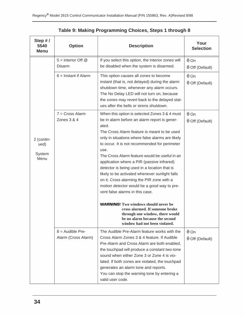
2 (contin-ued)
System Menu
5 = Interior Off @
Disarm
If you select this option, the interior zones will
be disabled when the system is disarmed.θ On
θ Off (Default)
6 = Instant if Alarm This option causes all zones to become
instant (that is, not delayed) during the alarm
shutdown time, whenever any alarm occurs.
The No Delay LED will not turn on, because
the zones may revert back to the delayed stat-
ues after the bells or sirens shutdown.
θ On
θ Off (Default)
7 = Cross Alarm
Zones 3 & 4
When this option is selected Zones 3 & 4 must
be in alarm before an alarm report is gener-
ated.
The Cross Alarm feature is meant to be used
only in situations where false alarms are likely
to occur. It is not recommended for perimeter
use.
The Cross Alarm feature would be useful in an
application where a PIR (passive infrared)
detector is being used in a location that is
likely to be activated whenever sunlight falls
on it. Cross alarming the PIR zone with a
motion detector would be a good way to pre-
vent false alarms in this case.
WARNING! Two windows should never be cross alarmed. If someone broke through one window, there would be no alarm because the second window had not been violated.
θ On
θ Off (Default)
8 = Audible Pre-
Alarm (Cross Alarm)
The Audible Pre-Alarm feature works with the
Cross Alarm Zones 3 & 4 feature. If Audible
Pre-Alarm and Cross Alarm are both enabled,
the touchpad will produce a constant two-tone
sound when either Zone 3 or Zone 4 is vio-
lated. If both zones are violated, the touchpad
generates an alarm tone and reports.
You can stop the warning tone by entering a
valid user code.
θ On
θ Off (Default)
Table 9: Making Programming Choices, Steps 1 through 8
Step # / 5540 Menu
Option DescriptionYour
Selection
35
Regency® Model 2615 Control Communicator Installation Manual (P/N 150863, Rev. A)Revised 8/98
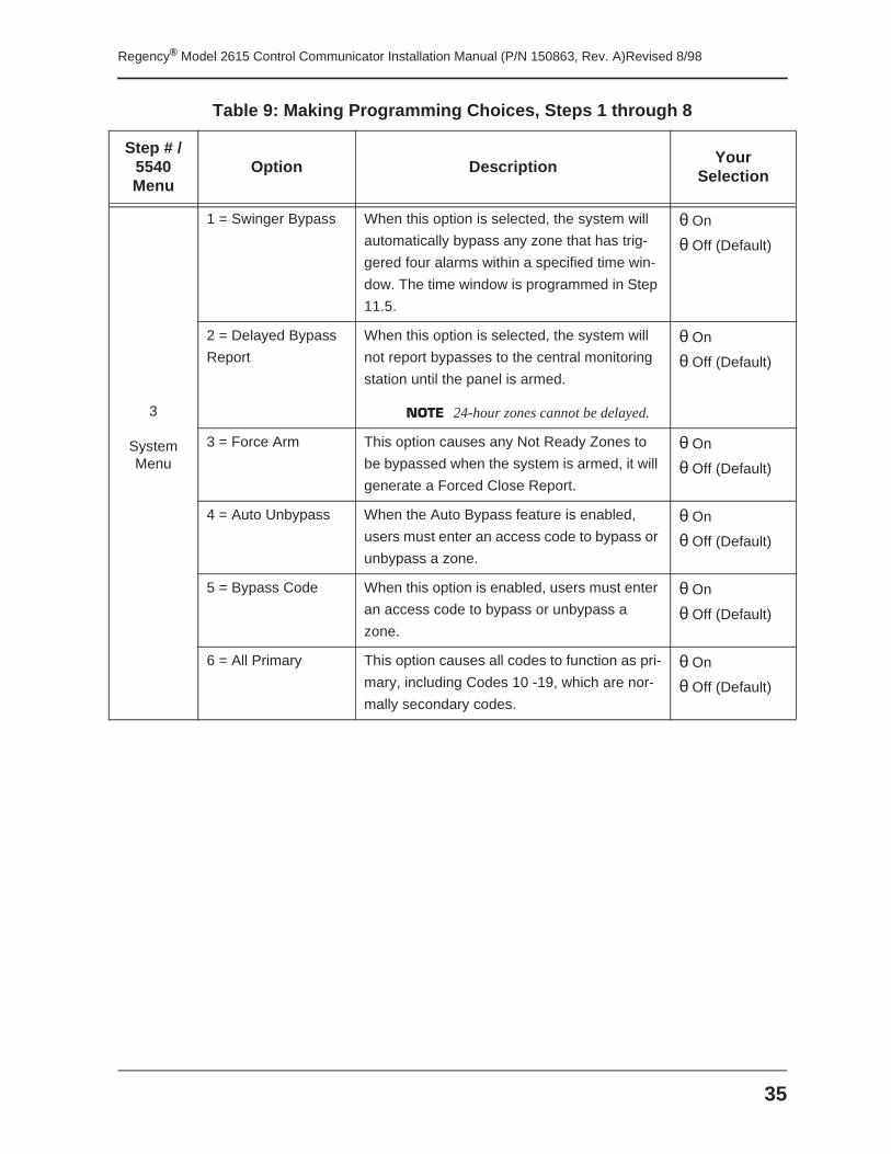
3
System Menu
1 = Swinger Bypass When this option is selected, the system will
automatically bypass any zone that has trig-
gered four alarms within a specified time win-
dow. The time window is programmed in Step
11.5.
θ On
θ Off (Default)
2 = Delayed Bypass
Report
When this option is selected, the system will
not report bypasses to the central monitoring
station until the panel is armed.
NOTE 24-hour zones cannot be delayed.
θ On
θ Off (Default)
3 = Force Arm This option causes any Not Ready Zones to
be bypassed when the system is armed, it will
generate a Forced Close Report.
θ On
θ Off (Default)
4 = Auto Unbypass When the Auto Bypass feature is enabled,
users must enter an access code to bypass or
unbypass a zone.
θ On
θ Off (Default)
5 = Bypass Code When this option is enabled, users must enter
an access code to bypass or unbypass a
zone.
θ On
θ Off (Default)
6 = All Primary This option causes all codes to function as pri-
mary, including Codes 10 -19, which are nor-
mally secondary codes.
θ On
θ Off (Default)
Table 9: Making Programming Choices, Steps 1 through 8
Step # / 5540 Menu
Option DescriptionYour
Selection
Regency® Model 2615 Control Communicator Installation Manual (P/N 150863, Rev. A)Revised 8/98
36
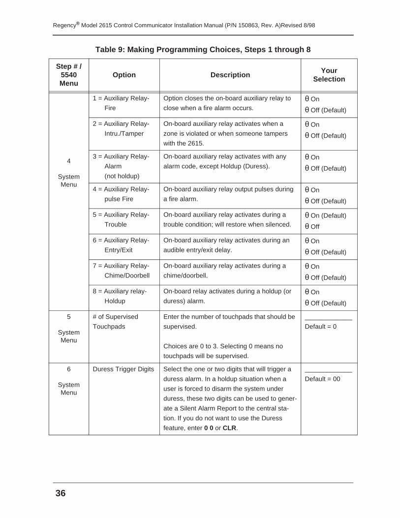
4
System Menu
1 = Auxiliary Relay-
Fire
Option closes the on-board auxiliary relay to
close when a fire alarm occurs.θ On
θ Off (Default)
2 = Auxiliary Relay-
Intru./Tamper
On-board auxiliary relay activates when a
zone is violated or when someone tampers
with the 2615.
θ On
θ Off (Default)
3 = Auxiliary Relay-
Alarm
(not holdup)
On-board auxiliary relay activates with any
alarm code, except Holdup (Duress).θ On
θ Off (Default)
4 = Auxiliary Relay-
pulse Fire
On-board auxiliary relay output pulses during
a fire alarm.θ On
θ Off (Default)
5 = Auxiliary Relay-
Trouble
On-board auxiliary relay activates during a
trouble condition; will restore when silenced.θ On (Default)
θ Off
6 = Auxiliary Relay-
Entry/Exit
On-board auxiliary relay activates during an
audible entry/exit delay.θ On
θ Off (Default)
7 = Auxiliary Relay-
Chime/Doorbell
On-board auxiliary relay activates during a
chime/doorbell.θ On
θ Off (Default)
8 = Auxiliary relay-
Holdup
On-board relay activates during a holdup (or
duress) alarm.θ On
θ Off (Default)
5
System Menu
# of Supervised
Touchpads
Enter the number of touchpads that should be
supervised.
Choices are 0 to 3. Selecting 0 means no
touchpads will be supervised.
_____________
Default = 0
6
System Menu
Duress Trigger Digits Select the one or two digits that will trigger a
duress alarm. In a holdup situation when a
user is forced to disarm the system under
duress, these two digits can be used to gener-
ate a Silent Alarm Report to the central sta-
tion. If you do not want to use the Duress
feature, enter 0 0 or CLR.
_____________
Default = 00
Table 9: Making Programming Choices, Steps 1 through 8
Step # / 5540 Menu
Option DescriptionYour
Selection
37
Regency® Model 2615 Control Communicator Installation Manual (P/N 150863, Rev. A)Revised 8/98
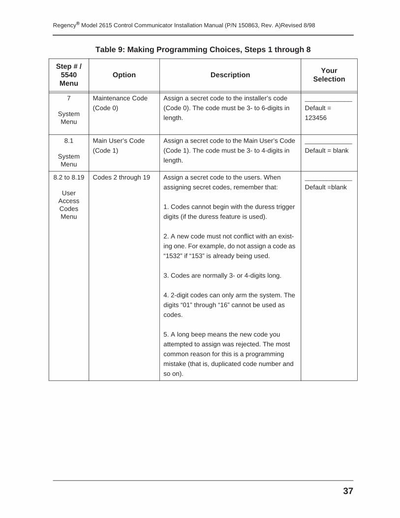
7
System Menu
Maintenance Code
(Code 0)
Assign a secret code to the installer’s code
(Code 0). The code must be 3- to 6-digits in
length.
_____________
Default =
123456
8.1
System Menu
Main User’s Code
(Code 1)
Assign a secret code to the Main User’s Code
(Code 1). The code must be 3- to 4-digits in
length.
_____________
Default = blank
8.2 to 8.19
User Access Codes Menu
Codes 2 through 19 Assign a secret code to the users. When
assigning secret codes, remember that:
1. Codes cannot begin with the duress trigger
digits (if the duress feature is used).
2. A new code must not conflict with an exist-
ing one. For example, do not assign a code as
“1532” if “153” is already being used.
3. Codes are normally 3- or 4-digits long.
4. 2-digit codes can only arm the system. The
digits “01” through “16” cannot be used as
codes.
5. A long beep means the new code you
attempted to assign was rejected. The most
common reason for this is a programming
mistake (that is, duplicated code number and
so on).
_____________
Default =blank
Table 9: Making Programming Choices, Steps 1 through 8
Step # / 5540 Menu
Option DescriptionYour
Selection
Regency® Model 2615 Control Communicator Installation Manual (P/N 150863, Rev. A)Revised 8/98
38
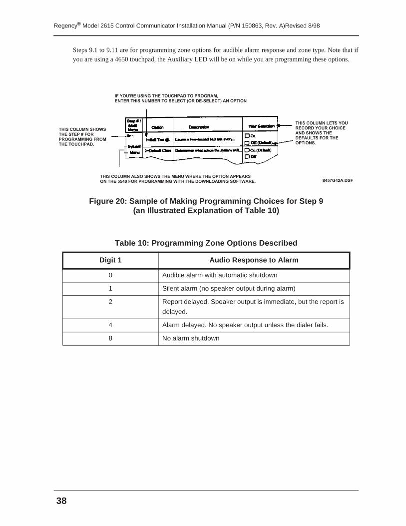
Steps 9.1 to 9.11 are for programming zone options for audible alarm response and zone type. Note that if
you are using a 4650 touchpad, the Auxiliary LED will be on while you are programming these options.
Figure 20: Sample of Making Programming Choices for Step 9(an Illustrated Explanation of Table 10)
Table 10: Programming Zone Options Described
Digit 1 Audio Response to Alarm
0 Audible alarm with automatic shutdown
1 Silent alarm (no speaker output during alarm)
2 Report delayed. Speaker output is immediate, but the report is
delayed.
4 Alarm delayed. No speaker output unless the dialer fails.
8 No alarm shutdown
8 4 5 7 G 4 2 A . D S F
I F Y O U ' R E U S I N G T H E T O U C H P A D T O P R O G R A M ,E N T E R T H I S N U M B E R T O S E L E C T ( O R D E - S E L E C T ) A N O P T I O N
T H I S C O L U M N S H O W ST H E S T E P # F O R P R O G R A M M I N G F R O M T H E T O U C H P A D .
T H I S C O L U M N A L S O S H O W S T H E M E N U W H E R E T H E O P T I O N A P P E A R SO N T H E 5 5 4 0 F O R P R O G R A M M I N G W I T H T H E D O W N L O A D I N G S O F T W A R E .
T H I S C O L U M N L E T S Y O U R E C O R D Y O U R C H O I C EA N D S H O W S T H ED E F A U L T S F O R T H E O P T I O N S .
39
Regency® Model 2615 Control Communicator Installation Manual (P/N 150863, Rev. A)Revised 8/98
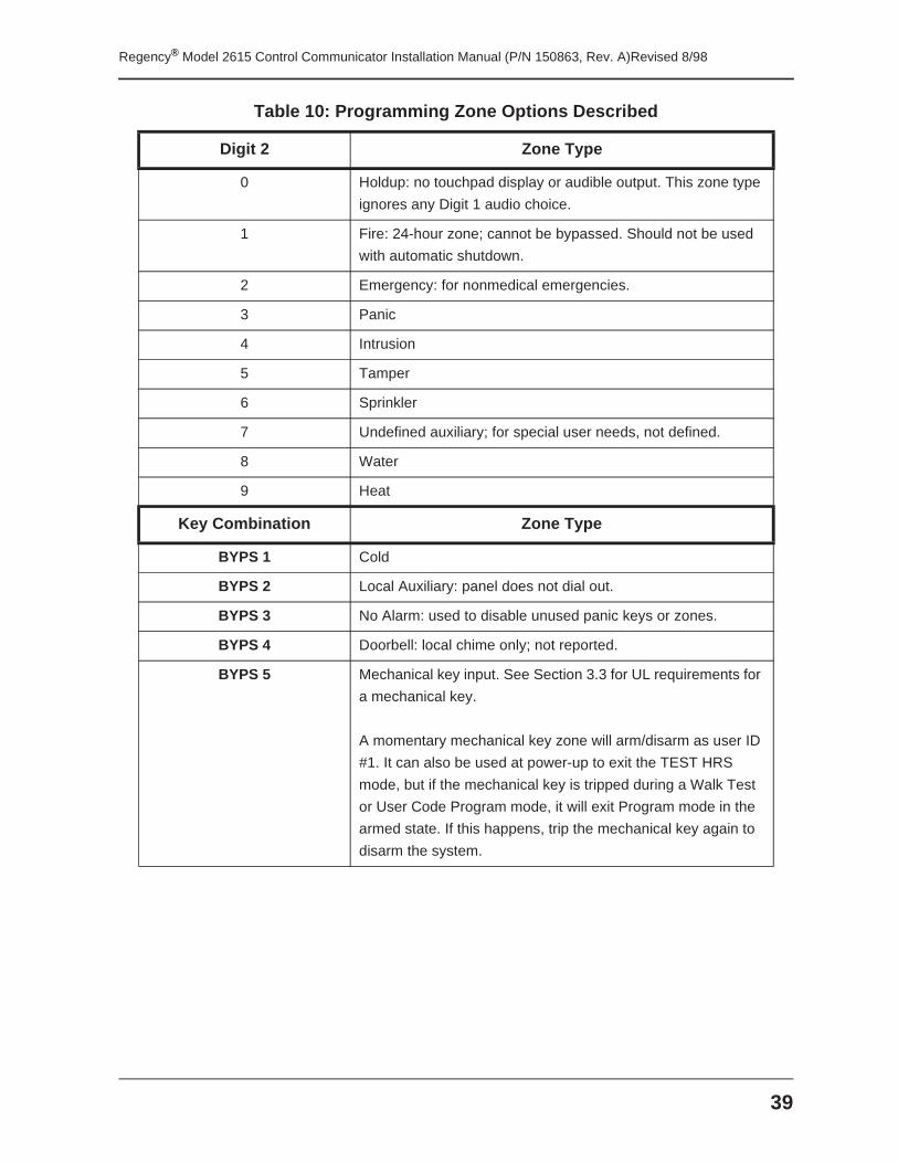
Digit 2 Zone Type
0 Holdup: no touchpad display or audible output. This zone type
ignores any Digit 1 audio choice.
1 Fire: 24-hour zone; cannot be bypassed. Should not be used
with automatic shutdown.
2 Emergency: for nonmedical emergencies.
3 Panic
4 Intrusion
5 Tamper
6 Sprinkler
7 Undefined auxiliary; for special user needs, not defined.
8 Water
9 Heat
Key Combination Zone Type
BYPS 1 Cold
BYPS 2 Local Auxiliary: panel does not dial out.
BYPS 3 No Alarm: used to disable unused panic keys or zones.
BYPS 4 Doorbell: local chime only; not reported.
BYPS 5 Mechanical key input. See Section 3.3 for UL requirements for
a mechanical key.
A momentary mechanical key zone will arm/disarm as user ID
#1. It can also be used at power-up to exit the TEST HRS
mode, but if the mechanical key is tripped during a Walk Test
or User Code Program mode, it will exit Program mode in the
armed state. If this happens, trip the mechanical key again to
disarm the system.
Table 10: Programming Zone Options Described
Regency® Model 2615 Control Communicator Installation Manual (P/N 150863, Rev. A)Revised 8/98
40
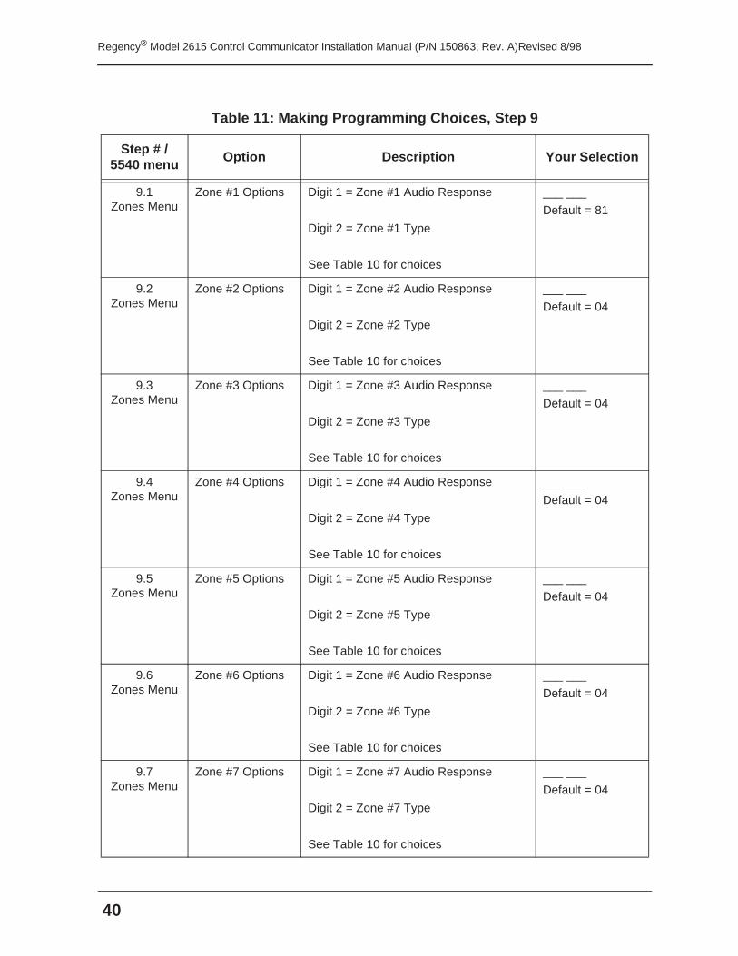
Table 11: Making Programming Choices, Step 9
Step # / 5540 menu Option Description Your Selection
9.1 Zones Menu
Zone #1 Options Digit 1 = Zone #1 Audio Response
Digit 2 = Zone #1 Type
See Table 10 for choices
___ ___
Default = 81
9.2 Zones Menu
Zone #2 Options Digit 1 = Zone #2 Audio Response
Digit 2 = Zone #2 Type
See Table 10 for choices
___ ___
Default = 04
9.3 Zones Menu
Zone #3 Options Digit 1 = Zone #3 Audio Response
Digit 2 = Zone #3 Type
See Table 10 for choices
___ ___
Default = 04
9.4 Zones Menu
Zone #4 Options Digit 1 = Zone #4 Audio Response
Digit 2 = Zone #4 Type
See Table 10 for choices
___ ___
Default = 04
9.5 Zones Menu
Zone #5 Options Digit 1 = Zone #5 Audio Response
Digit 2 = Zone #5 Type
See Table 10 for choices
___ ___
Default = 04
9.6 Zones Menu
Zone #6 Options Digit 1 = Zone #6 Audio Response
Digit 2 = Zone #6 Type
See Table 10 for choices
___ ___
Default = 04
9.7 Zones Menu
Zone #7 Options Digit 1 = Zone #7 Audio Response
Digit 2 = Zone #7 Type
See Table 10 for choices
___ ___
Default = 04
41
Regency® Model 2615 Control Communicator Installation Manual (P/N 150863, Rev. A)Revised 8/98
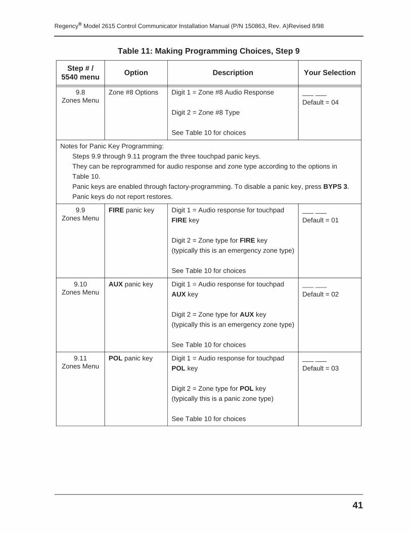
9.8 Zones Menu
Zone #8 Options Digit 1 = Zone #8 Audio Response
Digit 2 = Zone #8 Type
See Table 10 for choices
___ ___
Default = 04
Notes for Panic Key Programming:
Steps 9.9 through 9.11 program the three touchpad panic keys.
They can be reprogrammed for audio response and zone type according to the options in
Table 10.
Panic keys are enabled through factory-programming. To disable a panic key, press BYPS 3.
Panic keys do not report restores.
9.9 Zones Menu
FIRE panic key Digit 1 = Audio response for touchpad
FIRE key
Digit 2 = Zone type for FIRE key
(typically this is an emergency zone type)
See Table 10 for choices
___ ___
Default = 01
9.10Zones Menu
AUX panic key Digit 1 = Audio response for touchpad
AUX key
Digit 2 = Zone type for AUX key
(typically this is an emergency zone type)
See Table 10 for choices
___ ___
Default = 02
9.11 Zones Menu
POL panic key Digit 1 = Audio response for touchpad
POL key
Digit 2 = Zone type for POL key
(typically this is a panic zone type)
See Table 10 for choices
___ ___
Default = 03
Table 11: Making Programming Choices, Step 9
Step # / 5540 menu
Option Description Your Selection
Regency® Model 2615 Control Communicator Installation Manual (P/N 150863, Rev. A)Revised 8/98
42
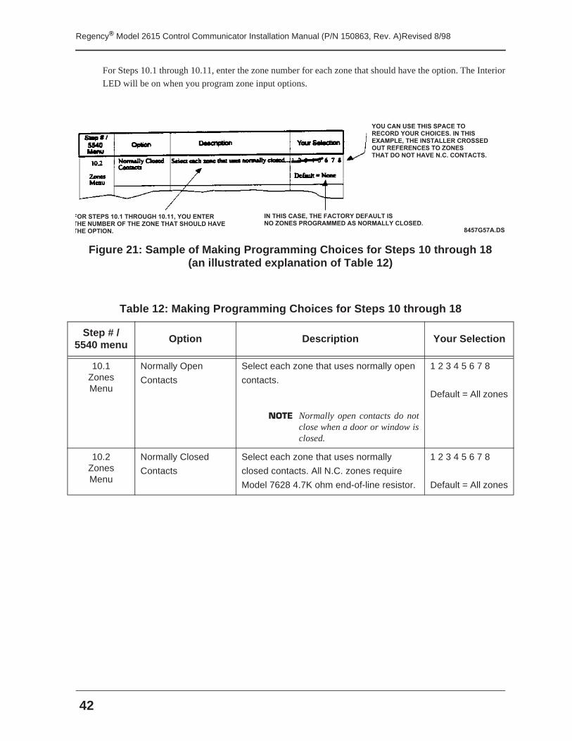
For Steps 10.1 through 10.11, enter the zone number for each zone that should have the option. The Interior
LED will be on when you program zone input options.
Figure 21: Sample of Making Programming Choices for Steps 10 through 18(an illustrated explanation of Table 12)
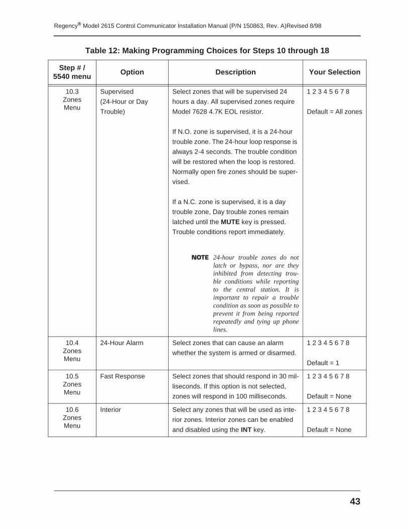
Table 12: Making Programming Choices for Steps 10 through 18
Step # / 5540 menu Option Description Your Selection
10.1Zones Menu
Normally Open
Contacts
Select each zone that uses normally open
contacts.
NOTE Normally open contacts do notclose when a door or window isclosed.
1 2 3 4 5 6 7 8
Default = All zones
10.2Zones Menu
Normally Closed
Contacts
Select each zone that uses normally
closed contacts. All N.C. zones require
Model 7628 4.7K ohm end-of-line resistor.
1 2 3 4 5 6 7 8
Default = All zones
8 4 5 7 G 5 7 A . D S F
F O R S T E P S 1 0 . 1 T H R O U G H 1 0 . 1 1 , Y O U E N T E RT H E N U M B E R O F T H E Z O N E T H A T S H O U L D H A V E T H E O P T I O N .
Y O U C A N U S E T H I S S P A C E T OR E C O R D Y O U R C H O I C E S . I N T H I S E X A M P L E , T H E I N S T A L L E R C R O S S E D O U T R E F E R E N C E S T O Z O N E ST H A T D O N O T H A V E N . C . C O N T A C T S .
I N T H I S C A S E , T H E F A C T O R Y D E F A U L T I SN O Z O N E S P R O G R A M M E D A S N O R M A L L Y C L O S E D .
43
Regency® Model 2615 Control Communicator Installation Manual (P/N 150863, Rev. A)Revised 8/98
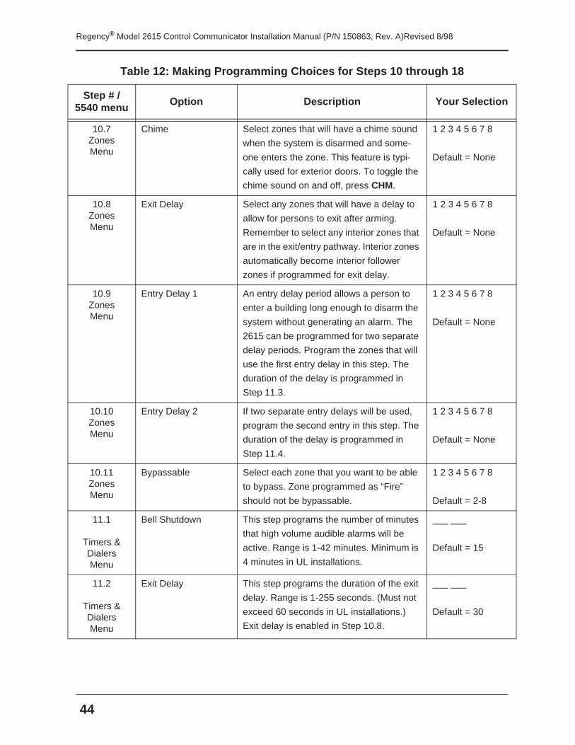
10.3Zones Menu
Supervised
(24-Hour or Day
Trouble)
Select zones that will be supervised 24
hours a day. All supervised zones require
Model 7628 4.7K EOL resistor.
If N.O. zone is supervised, it is a 24-hour
trouble zone. The 24-hour loop response is
always 2-4 seconds. The trouble condition
will be restored when the loop is restored.
Normally open fire zones should be super-
vised.
If a N.C. zone is supervised, it is a day
trouble zone, Day trouble zones remain
latched until the MUTE key is pressed.
Trouble conditions report immediately.
NOTE 24-hour trouble zones do notlatch or bypass, nor are theyinhibited from detecting trou-ble conditions while reportingto the central station. It isimportant to repair a troublecondition as soon as possible toprevent it from being reportedrepeatedly and tying up phonelines.
1 2 3 4 5 6 7 8
Default = All zones
10.4Zones Menu
24-Hour Alarm Select zones that can cause an alarm
whether the system is armed or disarmed.
1 2 3 4 5 6 7 8
Default = 1
10.5Zones Menu
Fast Response Select zones that should respond in 30 mil-
liseconds. If this option is not selected,
zones will respond in 100 milliseconds.
1 2 3 4 5 6 7 8
Default = None
10.6Zones Menu
Interior Select any zones that will be used as inte-
rior zones. Interior zones can be enabled
and disabled using the INT key.
1 2 3 4 5 6 7 8
Default = None
Table 12: Making Programming Choices for Steps 10 through 18
Step # / 5540 menu
Option Description Your Selection
Regency® Model 2615 Control Communicator Installation Manual (P/N 150863, Rev. A)Revised 8/98
44
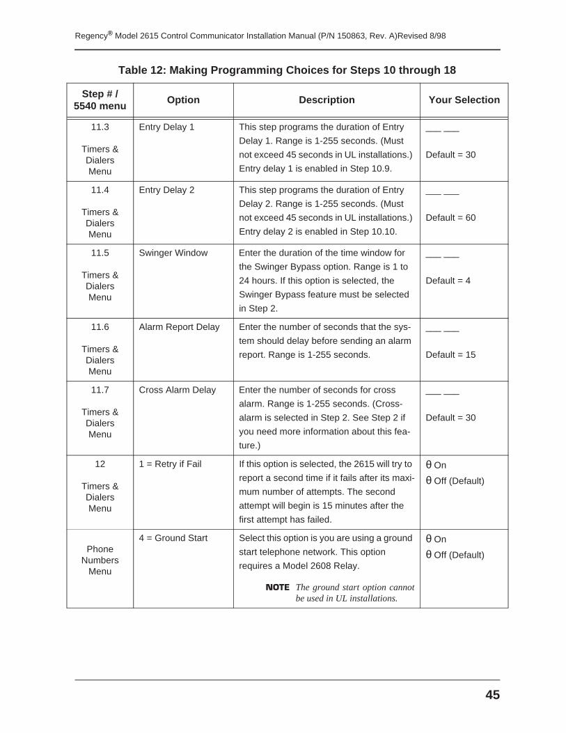
10.7Zones Menu
Chime Select zones that will have a chime sound
when the system is disarmed and some-
one enters the zone. This feature is typi-
cally used for exterior doors. To toggle the
chime sound on and off, press CHM.
1 2 3 4 5 6 7 8
Default = None
10.8Zones Menu
Exit Delay Select any zones that will have a delay to
allow for persons to exit after arming.
Remember to select any interior zones that
are in the exit/entry pathway. Interior zones
automatically become interior follower
zones if programmed for exit delay.
1 2 3 4 5 6 7 8
Default = None
10.9Zones Menu
Entry Delay 1 An entry delay period allows a person to
enter a building long enough to disarm the
system without generating an alarm. The
2615 can be programmed for two separate
delay periods. Program the zones that will
use the first entry delay in this step. The
duration of the delay is programmed in
Step 11.3.
1 2 3 4 5 6 7 8
Default = None
10.10Zones Menu
Entry Delay 2 If two separate entry delays will be used,
program the second entry in this step. The
duration of the delay is programmed in
Step 11.4.
1 2 3 4 5 6 7 8
Default = None
10.11Zones Menu
Bypassable Select each zone that you want to be able
to bypass. Zone programmed as “Fire”
should not be bypassable.
1 2 3 4 5 6 7 8
Default = 2-8
11.1
Timers & DialersMenu
Bell Shutdown This step programs the number of minutes
that high volume audible alarms will be
active. Range is 1-42 minutes. Minimum is
4 minutes in UL installations.
___ ___
Default = 15
11.2
Timers & DialersMenu
Exit Delay This step programs the duration of the exit
delay. Range is 1-255 seconds. (Must not
exceed 60 seconds in UL installations.)
Exit delay is enabled in Step 10.8.
___ ___
Default = 30
Table 12: Making Programming Choices for Steps 10 through 18
Step # / 5540 menu
Option Description Your Selection
45
Regency® Model 2615 Control Communicator Installation Manual (P/N 150863, Rev. A)Revised 8/98
11.3
Timers & DialersMenu
Entry Delay 1 This step programs the duration of Entry
Delay 1. Range is 1-255 seconds. (Must
not exceed 45 seconds in UL installations.)
Entry delay 1 is enabled in Step 10.9.
___ ___
Default = 30
11.4
Timers & DialersMenu
Entry Delay 2 This step programs the duration of Entry
Delay 2. Range is 1-255 seconds. (Must
not exceed 45 seconds in UL installations.)
Entry delay 2 is enabled in Step 10.10.
___ ___
Default = 60
11.5
Timers & DialersMenu
Swinger Window Enter the duration of the time window for
the Swinger Bypass option. Range is 1 to
24 hours. If this option is selected, the
Swinger Bypass feature must be selected
in Step 2.
___ ___
Default = 4
11.6
Timers & DialersMenu
Alarm Report Delay Enter the number of seconds that the sys-
tem should delay before sending an alarm
report. Range is 1-255 seconds.
___ ___
Default = 15
11.7
Timers & Dialers Menu
Cross Alarm Delay Enter the number of seconds for cross
alarm. Range is 1-255 seconds. (Cross-
alarm is selected in Step 2. See Step 2 if
you need more information about this fea-
ture.)
___ ___
Default = 30
12
Timers & Dialers Menu
1 = Retry if Fail If this option is selected, the 2615 will try to
report a second time if it fails after its maxi-
mum number of attempts. The second
attempt will begin is 15 minutes after the
first attempt has failed.
θ On
θ Off (Default)
Phone Numbers
Menu
4 = Ground Start Select this option is you are using a ground
start telephone network. This option
requires a Model 2608 Relay.
NOTE The ground start option cannotbe used in UL installations.
θ On
θ Off (Default)
Table 12: Making Programming Choices for Steps 10 through 18
Step # / 5540 menu
Option Description Your Selection
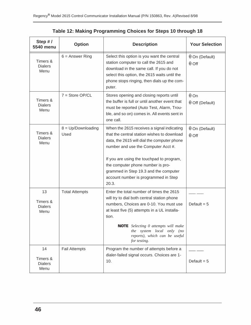
Regency® Model 2615 Control Communicator Installation Manual (P/N 150863, Rev. A)Revised 8/98
46
Timers & Dialers Menu
6 = Answer Ring Select this option is you want the central
station computer to call the 2615 and
download in the same call. If you do not
select this option, the 2615 waits until the
phone stops ringing, then dials up the com-
puter.
θ On (Default)
θ Off
Timers & Dialers Menu
7 = Store OP/CL Stores opening and closing reports until
the buffer is full or until another event that
must be reported (Auto Test, Alarm, Trou-
ble, and so on) comes in. All events sent in
one call.
θ On
θ Off (Default)
Timers & Dialers Menu
8 = Up/Downloading
Used
When the 2615 receives a signal indicating
that the central station wishes to download
data, the 2615 will dial the computer phone
number and use the Computer Acct #.
If you are using the touchpad to program,
the computer phone number is pro-
grammed in Step 19.3 and the computer
account number is programmed in Step
20.3.
θ On (Default)
θ Off
13
Timers & Dialers Menu
Total Attempts Enter the total number of times the 2615
will try to dial both central station phone
numbers, Choices are 0-10. You must use
at least five (5) attempts in a UL installa-
tion.
NOTE Selecting 0 attempts will makethe system local only (noreports), which can be usefulfor testing.
___ ___
Default = 5
14
Timers & Dialers Menu
Fail Attempts Program the number of attempts before a
dialer-failed signal occurs. Choices are 1-
10.
___ ___
Default = 5
Table 12: Making Programming Choices for Steps 10 through 18
Step # / 5540 menu
Option Description Your Selection
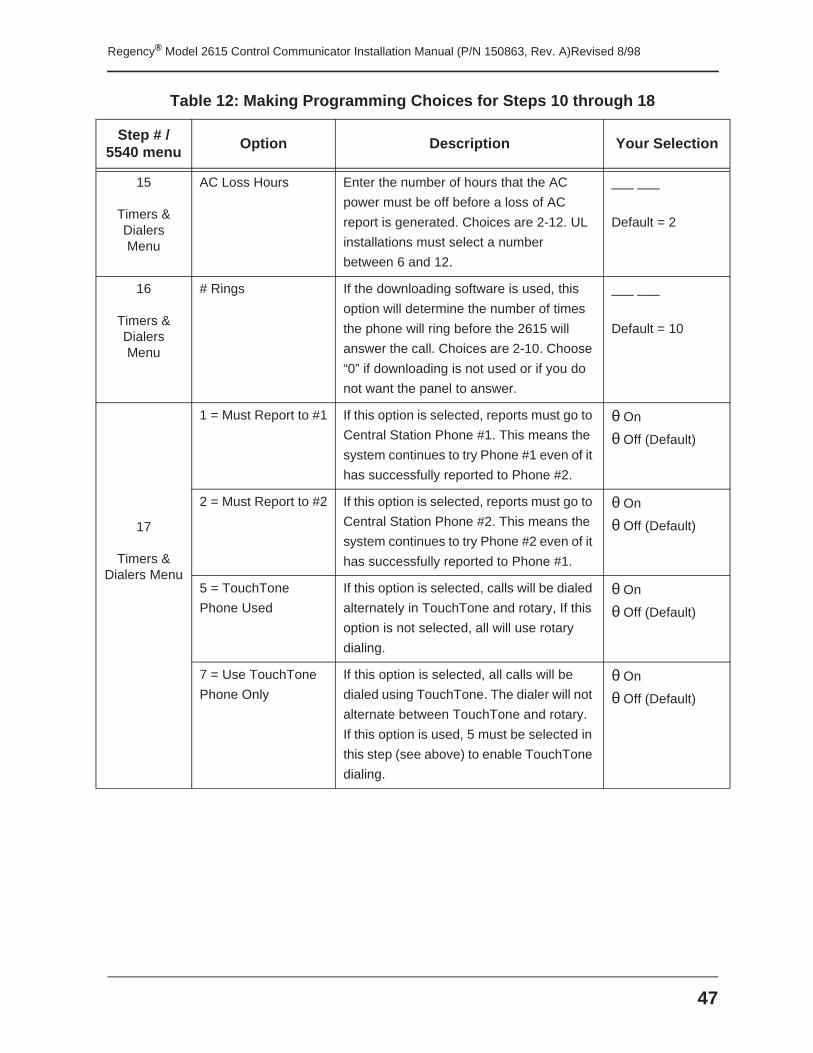
47
Regency® Model 2615 Control Communicator Installation Manual (P/N 150863, Rev. A)Revised 8/98
15
Timers & Dialers Menu
AC Loss Hours Enter the number of hours that the AC
power must be off before a loss of AC
report is generated. Choices are 2-12. UL
installations must select a number
between 6 and 12.
___ ___
Default = 2
16
Timers & Dialers Menu
# Rings If the downloading software is used, this
option will determine the number of times
the phone will ring before the 2615 will
answer the call. Choices are 2-10. Choose
“0” if downloading is not used or if you do
not want the panel to answer.
___ ___
Default = 10
17
Timers & Dialers Menu
1 = Must Report to #1 If this option is selected, reports must go to
Central Station Phone #1. This means the
system continues to try Phone #1 even of it
has successfully reported to Phone #2.
θ On
θ Off (Default)
2 = Must Report to #2 If this option is selected, reports must go to
Central Station Phone #2. This means the
system continues to try Phone #2 even of it
has successfully reported to Phone #1.
θ On
θ Off (Default)
5 = TouchTone
Phone Used
If this option is selected, calls will be dialed
alternately in TouchTone and rotary, If this
option is not selected, all will use rotary
dialing.
θ On
θ Off (Default)
7 = Use TouchTone
Phone Only
If this option is selected, all calls will be
dialed using TouchTone. The dialer will not
alternate between TouchTone and rotary.
If this option is used, 5 must be selected in
this step (see above) to enable TouchTone
dialing.
θ On
θ Off (Default)
Table 12: Making Programming Choices for Steps 10 through 18
Step # / 5540 menu
Option Description Your Selection
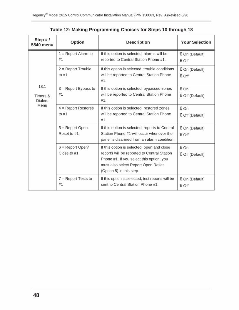
Regency® Model 2615 Control Communicator Installation Manual (P/N 150863, Rev. A)Revised 8/98
48
18.1
Timers & Dialers Menu
1 = Report Alarm to
#1
If this option is selected, alarms will be
reported to Central Station Phone #1.θ On (Default)
θ Off
2 = Report Trouble
to #1
If this option is selected, trouble conditions
will be reported to Central Station Phone
#1.
θ On (Default)
θ Off
3 = Report Bypass to
#1
If this option is selected, bypassed zones
will be reported to Central Station Phone
#1.
θ On
θ Off (Default)
4 = Report Restores
to #1
If this option is selected, restored zones
will be reported to Central Station Phone
#1.
θ On
θ Off (Default)
5 = Report Open-
Reset to #1
If this option is selected, reports to Central
Station Phone #1 will occur whenever the
panel is disarmed from an alarm condition.
θ On (Default)
θ Off
6 = Report Open/
Close to #1
If this option is selected, open and close
reports will be reported to Central Station
Phone #1. If you select this option, you
must also select Report Open Reset
(Option 5) in this step.
θ On
θ Off (Default)
7 = Report Tests to
#1
If this option is selected, test reports will be
sent to Central Station Phone #1.θ On (Default)
θ Off
Table 12: Making Programming Choices for Steps 10 through 18
Step # / 5540 menu
Option Description Your Selection
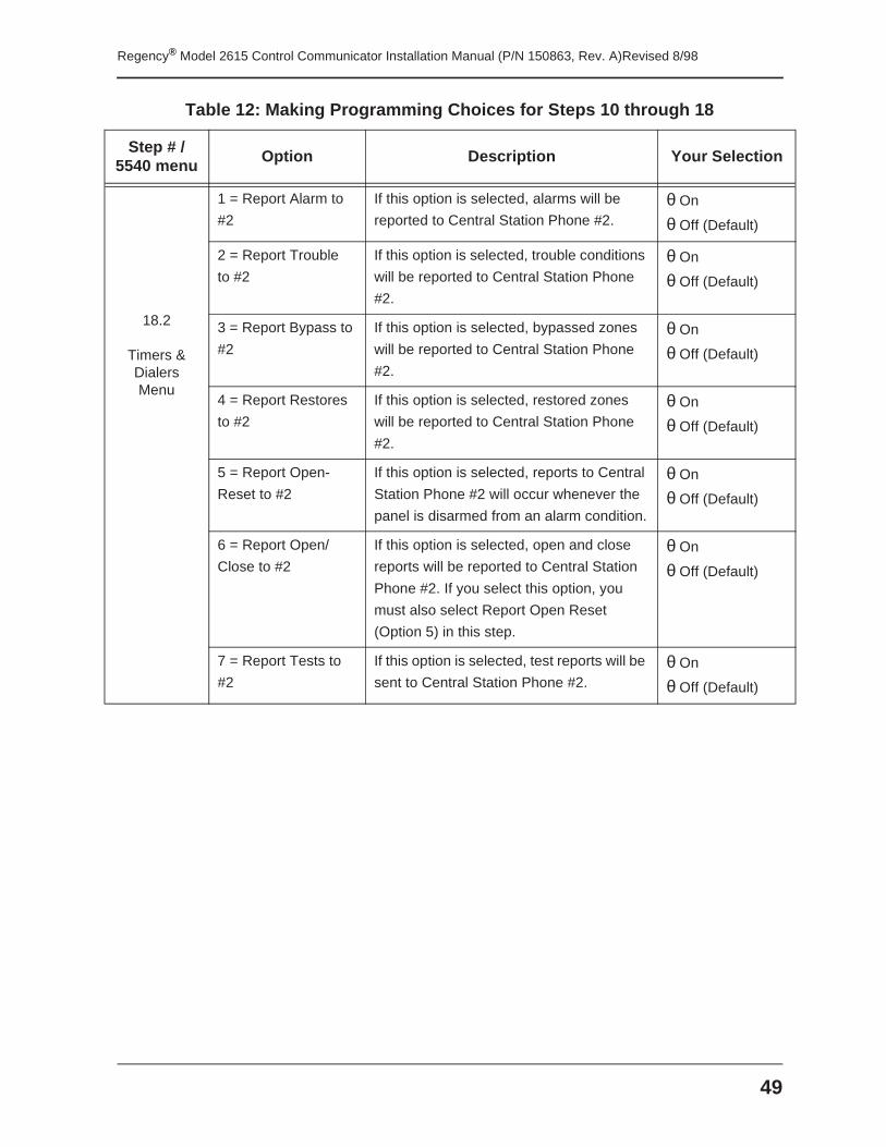
49
Regency® Model 2615 Control Communicator Installation Manual (P/N 150863, Rev. A)Revised 8/98
18.2
Timers & Dialers Menu
1 = Report Alarm to
#2
If this option is selected, alarms will be
reported to Central Station Phone #2.θ On
θ Off (Default)
2 = Report Trouble
to #2
If this option is selected, trouble conditions
will be reported to Central Station Phone
#2.
θ On
θ Off (Default)
3 = Report Bypass to
#2
If this option is selected, bypassed zones
will be reported to Central Station Phone
#2.
θ On
θ Off (Default)
4 = Report Restores
to #2
If this option is selected, restored zones
will be reported to Central Station Phone
#2.
θ On
θ Off (Default)
5 = Report Open-
Reset to #2
If this option is selected, reports to Central
Station Phone #2 will occur whenever the
panel is disarmed from an alarm condition.
θ On
θ Off (Default)
6 = Report Open/
Close to #2
If this option is selected, open and close
reports will be reported to Central Station
Phone #2. If you select this option, you
must also select Report Open Reset
(Option 5) in this step.
θ On
θ Off (Default)
7 = Report Tests to
#2
If this option is selected, test reports will be
sent to Central Station Phone #2.θ On
θ Off (Default)
Table 12: Making Programming Choices for Steps 10 through 18
Step # / 5540 menu
Option Description Your Selection
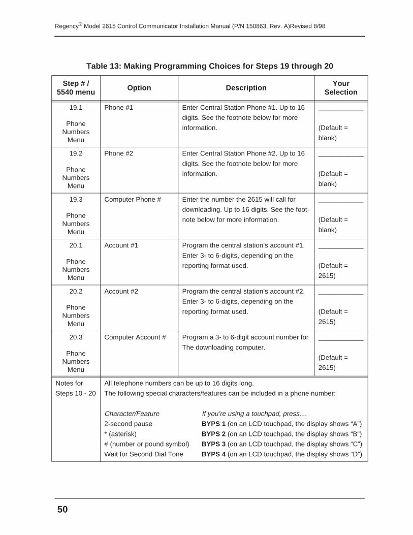
Regency® Model 2615 Control Communicator Installation Manual (P/N 150863, Rev. A)Revised 8/98
50
Table 13: Making Programming Choices for Steps 19 through 20
Step # / 5540 menu Option Description Your
Selection
19.1
Phone Numbers
Menu
Phone #1 Enter Central Station Phone #1. Up to 16
digits. See the footnote below for more
information.
____________
(Default =
blank)
19.2
Phone Numbers
Menu
Phone #2 Enter Central Station Phone #2. Up to 16
digits. See the footnote below for more
information.
____________
(Default =
blank)
19.3
Phone Numbers
Menu
Computer Phone # Enter the number the 2615 will call for
downloading. Up to 16 digits. See the foot-
note below for more information.
____________
(Default =
blank)
20.1
Phone Numbers
Menu
Account #1 Program the central station’s account #1.
Enter 3- to 6-digits, depending on the
reporting format used.
____________
(Default =
2615)
20.2
Phone Numbers
Menu
Account #2 Program the central station’s account #2.
Enter 3- to 6-digits, depending on the
reporting format used.
____________
(Default =
2615)
20.3
Phone Numbers
Menu
Computer Account # Program a 3- to 6-digit account number for
The downloading computer.
____________
(Default =
2615)
Notes for
Steps 10 - 20
All telephone numbers can be up to 16 digits long.
The following special characters/features can be included in a phone number:
Character/Feature If you’re using a touchpad, press....
2-second pause BYPS 1 (on an LCD touchpad, the display shows “A”)
* (asterisk) BYPS 2 (on an LCD touchpad, the display shows “B”)
# (number or pound symbol) BYPS 3 (on an LCD touchpad, the display shows “C”)
Wait for Second Dial Tone BYPS 4 (on an LCD touchpad, the display shows “D”)
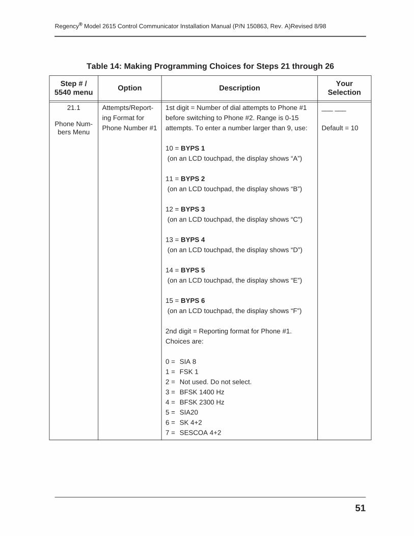
51
Regency® Model 2615 Control Communicator Installation Manual (P/N 150863, Rev. A)Revised 8/98
Table 14: Making Programming Choices for Steps 21 through 26
Step # / 5540 menu Option Description Your
Selection
21.1
Phone Num-bers Menu
Attempts/Report-
ing Format for
Phone Number #1
1st digit = Number of dial attempts to Phone #1
before switching to Phone #2. Range is 0-15
attempts. To enter a number larger than 9, use:
10 = BYPS 1
(on an LCD touchpad, the display shows “A”)
11 = BYPS 2
(on an LCD touchpad, the display shows “B”)
12 = BYPS 3
(on an LCD touchpad, the display shows “C”)
13 = BYPS 4
(on an LCD touchpad, the display shows “D”)
14 = BYPS 5
(on an LCD touchpad, the display shows “E”)
15 = BYPS 6
(on an LCD touchpad, the display shows “F”)
2nd digit = Reporting format for Phone #1.
Choices are:
0 = SIA 8
1 = FSK 1
2 = Not used. Do not select.
3 = BFSK 1400 Hz
4 = BFSK 2300 Hz
5 = SIA20
6 = SK 4+2
7 = SESCOA 4+2
___ ___
Default = 10
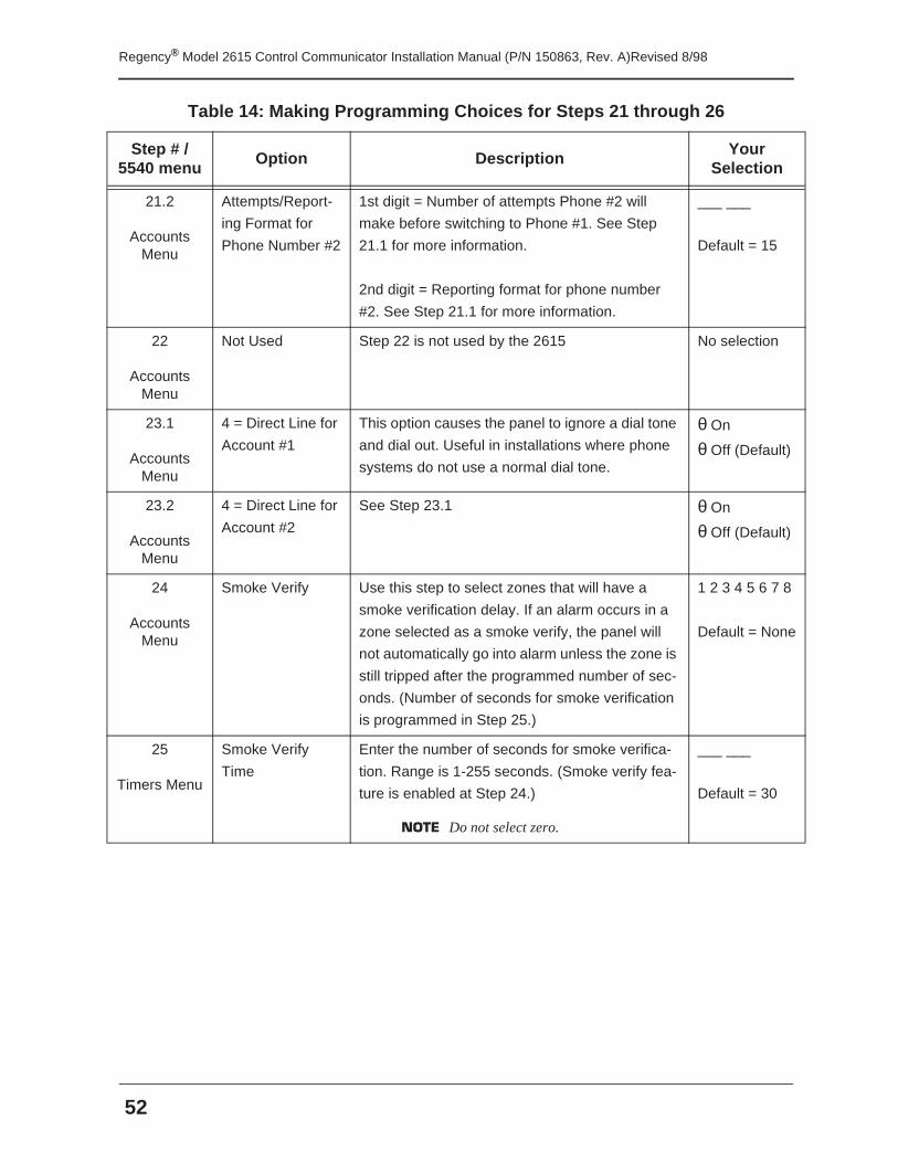
Regency® Model 2615 Control Communicator Installation Manual (P/N 150863, Rev. A)Revised 8/98
52
21.2
Accounts Menu
Attempts/Report-
ing Format for
Phone Number #2
1st digit = Number of attempts Phone #2 will
make before switching to Phone #1. See Step
21.1 for more information.
2nd digit = Reporting format for phone number
#2. See Step 21.1 for more information.
___ ___
Default = 15
22
Accounts Menu
Not Used Step 22 is not used by the 2615 No selection
23.1
Accounts Menu
4 = Direct Line for
Account #1
This option causes the panel to ignore a dial tone
and dial out. Useful in installations where phone
systems do not use a normal dial tone.
θ On
θ Off (Default)
23.2
Accounts Menu
4 = Direct Line for
Account #2
See Step 23.1 θ On
θ Off (Default)
24
Accounts Menu
Smoke Verify Use this step to select zones that will have a
smoke verification delay. If an alarm occurs in a
zone selected as a smoke verify, the panel will
not automatically go into alarm unless the zone is
still tripped after the programmed number of sec-
onds. (Number of seconds for smoke verification
is programmed in Step 25.)
1 2 3 4 5 6 7 8
Default = None
25
Timers Menu
Smoke Verify
Time
Enter the number of seconds for smoke verifica-
tion. Range is 1-255 seconds. (Smoke verify fea-
ture is enabled at Step 24.)
NOTE Do not select zero.
___ ___
Default = 30
Table 14: Making Programming Choices for Steps 21 through 26
Step # / 5540 menu
Option Description Your Selection
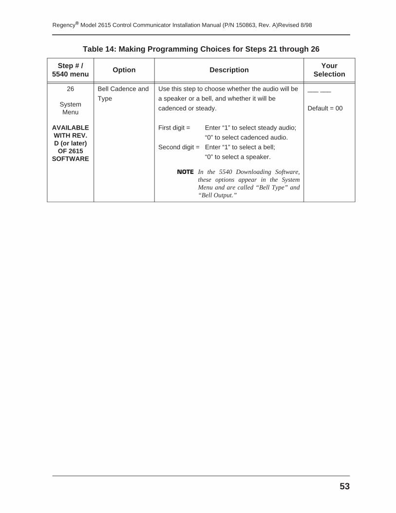
53
Regency® Model 2615 Control Communicator Installation Manual (P/N 150863, Rev. A)Revised 8/98
26
System Menu
AVAILABLE WITH REV. D (or later)
OF 2615 SOFTWARE
Bell Cadence and
Type
Use this step to choose whether the audio will be
a speaker or a bell, and whether it will be
cadenced or steady.
First digit = Enter “1” to select steady audio;
“0” to select cadenced audio.
Second digit = Enter “1” to select a bell;
“0” to select a speaker.
NOTE In the 5540 Downloading Software,these options appear in the SystemMenu and are called “Bell Type” and“Bell Output.”
___ ___
Default = 00
Table 14: Making Programming Choices for Steps 21 through 26
Step # / 5540 menu
Option Description Your Selection
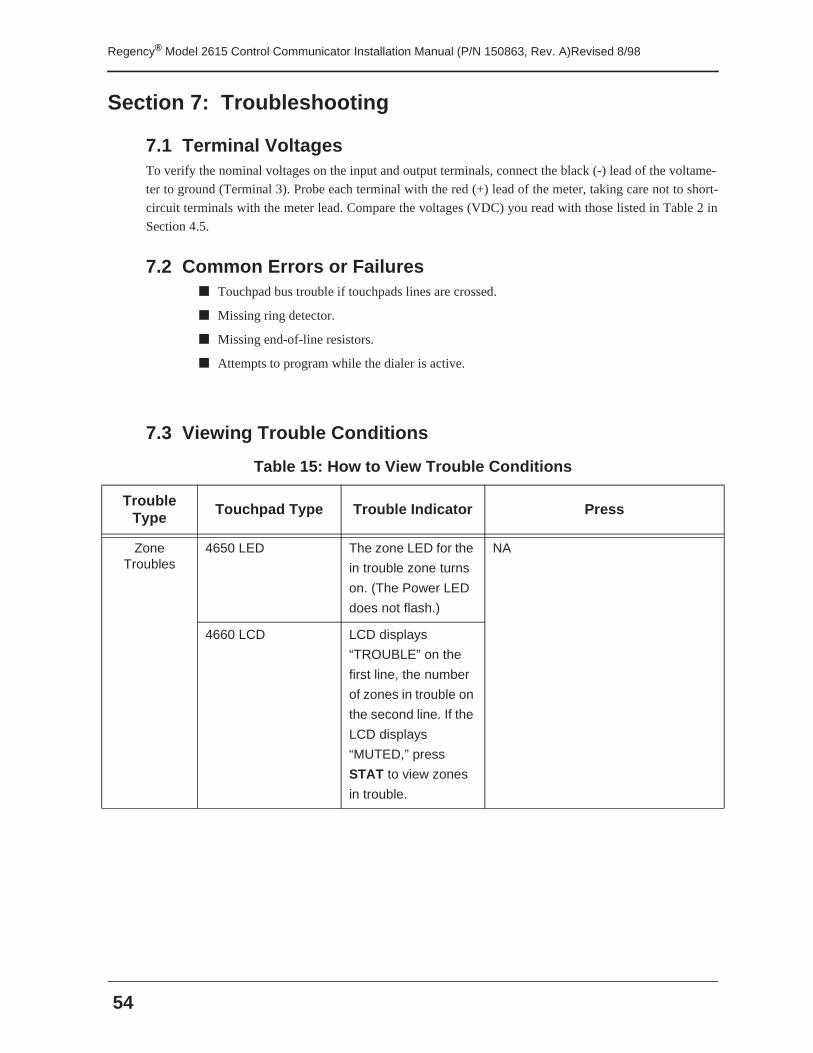
Regency® Model 2615 Control Communicator Installation Manual (P/N 150863, Rev. A)Revised 8/98
54
Section 7: Troubleshooting
7.1 Terminal VoltagesTo verify the nominal voltages on the input and output terminals, connect the black (-) lead of the voltame-
ter to ground (Terminal 3). Probe each terminal with the red (+) lead of the meter, taking care not to short-
circuit terminals with the meter lead. Compare the voltages (VDC) you read with those listed in Table 2 in
Section 4.5.
7.2 Common Errors or Failures■ Touchpad bus trouble if touchpads lines are crossed.
■ Missing ring detector.
■ Missing end-of-line resistors.
■ Attempts to program while the dialer is active.
7.3 Viewing Trouble Conditions
Table 15: How to View Trouble Conditions
Trouble Type
Touchpad Type Trouble Indicator Press
Zone Troubles
4650 LED The zone LED for the
in trouble zone turns
on. (The Power LED
does not flash.)
NA
4660 LCD LCD displays
“TROUBLE” on the
first line, the number
of zones in trouble on
the second line. If the
LCD displays
“MUTED,” press
STAT to view zones
in trouble.
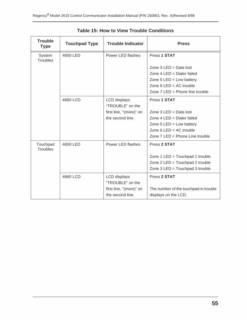
55
Regency® Model 2615 Control Communicator Installation Manual (P/N 150863, Rev. A)Revised 8/98
System Troubles
4650 LED Power LED flashes Press 1 STAT
Zone 3 LED = Data lost
Zone 4 LED = Dialer failed
Zone 5 LED = Low battery
Zone 6 LED = AC trouble
Zone 7 LED = Phone line trouble
4660 LCD LCD displays
“TROUBLE” on the
first line, “(more)” on
the second line.
Press 1 STAT
Zone 3 LED = Data lost
Zone 4 LED = Dialer failed
Zone 5 LED = Low battery
Zone 6 LED = AC trouble
Zone 7 LED = Phone Line trouble
Touchpad Troubles
4650 LED Power LED flashes Press 2 STAT
Zone 1 LED = Touchpad 1 trouble
Zone 2 LED = Touchpad 2 trouble
Zone 3 LED = Touchpad 3 trouble
4660 LCD LCD displays
“TROUBLE” on the
first line, “(more)” on
the second line.
Press 2 STAT
The number of the touchpad in trouble
displays on the LCD.
Table 15: How to View Trouble Conditions
Trouble Type
Touchpad Type Trouble Indicator Press
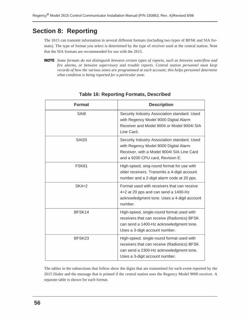
Regency® Model 2615 Control Communicator Installation Manual (P/N 150863, Rev. A)Revised 8/98
56
Section 8: ReportingThe 2615 can transmit information in several different formats (including two types of BFSK and SIA for-
mats). The type of format you select is determined by the type of receiver used at the central station. Note
that the SIA formats are recommended for use with the 2615.
NOTE Some formats do not distinguish between certain types of reports, such as between waterflow andfire alarms, or between supervisory and trouble reports. Central station personnel must keeprecords of how the various zones are programmed at each account; this helps personnel determinewhat condition is being reported for a particular zone.
The tables in the subsections that follow show the digits that are transmitted for each event reported by the
2615 Dialer and the message that is printed if the central station uses the Regency Model 9000 receiver. A
separate table is shown for each format.
Table 16: Reporting Formats, Described
Format Description
SAI8 Security Industry Association standard. Used
with Regency Model 9000 Digital Alarm
Receiver and Model 9004 or Model 9004I SIA
Line Card.
SAI20 Security Industry Association standard. Used
with Regency Model 9000 Digital Alarm
Receiver, with a Model 9004I SIA Line Card
and a 9200 CPU card, Revision E.
FSK81 High-speed, sing-round format for use with
older receivers. Transmits a 4-digit account
number and a 2-digit alarm code at 20 pps.
SK4+2 Format used with receivers that can receive
4+2 at 20 pps and can send a 1400-Hz
acknowledgment tone. Uses a 4-digit account
number.
BFSK14 High-speed, single-round format used with
receivers that can receive (Radionics) BFSK
can send a 1400-Hz acknowledgment tone.
Uses a 3-digit account number.
BFSK23 High-speed, single-round format used with
receivers that can receive (Radionics) BFSK
can send a 2300-Hz acknowledgment tone.
Uses a 3-digit account number.
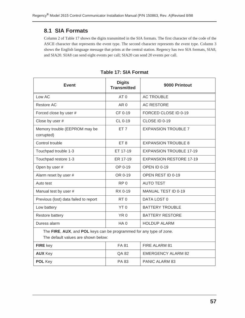
57
Regency® Model 2615 Control Communicator Installation Manual (P/N 150863, Rev. A)Revised 8/98
8.1 SIA FormatsColumn 2 of Table 17 shows the digits transmitted in the SIA formats. The first character of the code of the
ASCII character that represents the event type. The second character represents the event type. Column 3
shows the English language message that prints at the central station. Regency has two SIA formats, SIA8,
and SIA20. SIA8 can send eight events per call; SIA20 can send 20 events per call.
Table 17: SIA Format
Event Digits Transmitted 9000 Printout
Low AC AT 0 AC TROUBLE
Restore AC AR 0 AC RESTORE
Forced close by user # CF 0-19 FORCED CLOSE ID 0-19
Close by user # CL 0-19 CLOSE ID 0-19
Memory trouble (EEPROM may be
corrupted)
ET 7 EXPANSION TROUBLE 7
Control trouble ET 8 EXPANSION TROUBLE 8
Touchpad trouble 1-3 ET 17-19 EXPANSION TROUBLE 17-19
Touchpad restore 1-3 ER 17-19 EXPANSION RESTORE 17-19
Open by user # OP 0-19 OPEN ID 0-19
Alarm reset by user # OR 0-19 OPEN REST ID 0-19
Auto test RP 0 AUTO TEST
Manual test by user # RX 0-19 MANUAL TEST ID 0-19
Previous (lost) data failed to report RT 0 DATA LOST 0
Low battery YT 0 BATTERY TROUBLE
Restore battery YR 0 BATTERY RESTORE
Duress alarm HA 0 HOLDUP ALARM
The FIRE, AUX, and POL keys can be programmed for any type of zone.
The default values are shown below:
FIRE key FA 81 FIRE ALARM 81
AUX Key QA 82 EMERGENCY ALARM 82
POL Key PA 83 PANIC ALARM 83
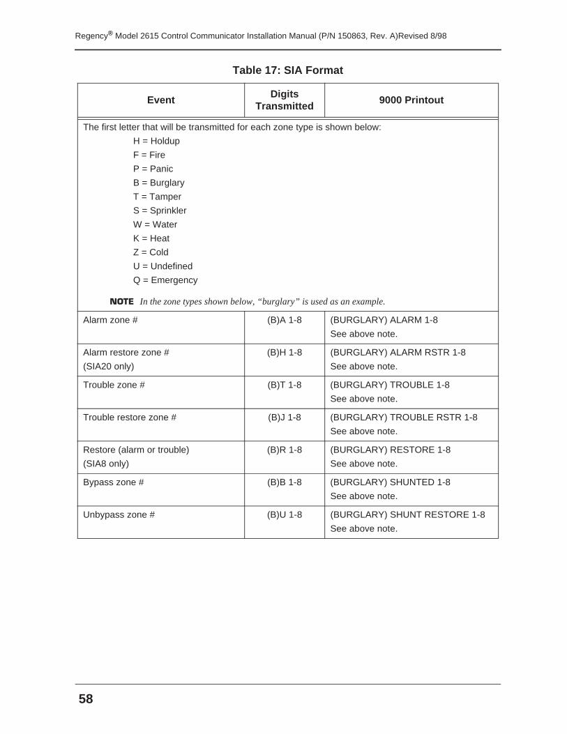
Regency® Model 2615 Control Communicator Installation Manual (P/N 150863, Rev. A)Revised 8/98
58
The first letter that will be transmitted for each zone type is shown below:
H = Holdup
F = Fire
P = Panic
B = Burglary
T = Tamper
S = Sprinkler
W = Water
K = Heat
Z = Cold
U = Undefined
Q = Emergency
NOTE In the zone types shown below, “burglary” is used as an example.
Alarm zone # (B)A 1-8 (BURGLARY) ALARM 1-8
See above note.
Alarm restore zone #
(SIA20 only)
(B)H 1-8 (BURGLARY) ALARM RSTR 1-8
See above note.
Trouble zone # (B)T 1-8 (BURGLARY) TROUBLE 1-8
See above note.
Trouble restore zone # (B)J 1-8 (BURGLARY) TROUBLE RSTR 1-8
See above note.
Restore (alarm or trouble)
(SIA8 only)
(B)R 1-8 (BURGLARY) RESTORE 1-8
See above note.
Bypass zone # (B)B 1-8 (BURGLARY) SHUNTED 1-8
See above note.
Unbypass zone # (B)U 1-8 (BURGLARY) SHUNT RESTORE 1-8
See above note.
Table 17: SIA Format
Event Digits Transmitted
9000 Printout
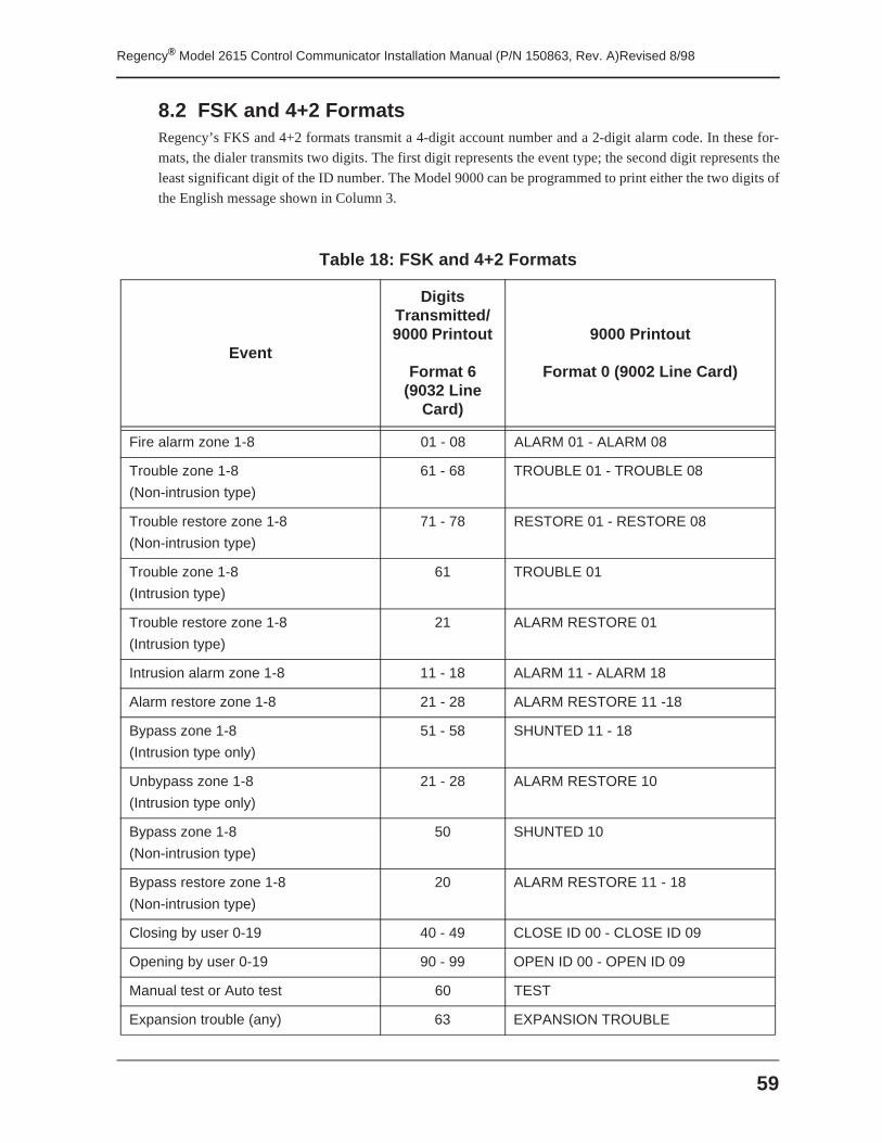
59
Regency® Model 2615 Control Communicator Installation Manual (P/N 150863, Rev. A)Revised 8/98
8.2 FSK and 4+2 FormatsRegency’s FKS and 4+2 formats transmit a 4-digit account number and a 2-digit alarm code. In these for-
mats, the dialer transmits two digits. The first digit represents the event type; the second digit represents the
least significant digit of the ID number. The Model 9000 can be programmed to print either the two digits of
the English message shown in Column 3.
Table 18: FSK and 4+2 Formats
Event
Digits Transmitted/ 9000 Printout
Format 6 (9032 Line
Card)
9000 Printout
Format 0 (9002 Line Card)
Fire alarm zone 1-8 01 - 08 ALARM 01 - ALARM 08
Trouble zone 1-8
(Non-intrusion type)
61 - 68 TROUBLE 01 - TROUBLE 08
Trouble restore zone 1-8
(Non-intrusion type)
71 - 78 RESTORE 01 - RESTORE 08
Trouble zone 1-8
(Intrusion type)
61 TROUBLE 01
Trouble restore zone 1-8
(Intrusion type)
21 ALARM RESTORE 01
Intrusion alarm zone 1-8 11 - 18 ALARM 11 - ALARM 18
Alarm restore zone 1-8 21 - 28 ALARM RESTORE 11 -18
Bypass zone 1-8
(Intrusion type only)
51 - 58 SHUNTED 11 - 18
Unbypass zone 1-8
(Intrusion type only)
21 - 28 ALARM RESTORE 10
Bypass zone 1-8
(Non-intrusion type)
50 SHUNTED 10
Bypass restore zone 1-8
(Non-intrusion type)
20 ALARM RESTORE 11 - 18
Closing by user 0-19 40 - 49 CLOSE ID 00 - CLOSE ID 09
Opening by user 0-19 90 - 99 OPEN ID 00 - OPEN ID 09
Manual test or Auto test 60 TEST
Expansion trouble (any) 63 EXPANSION TROUBLE
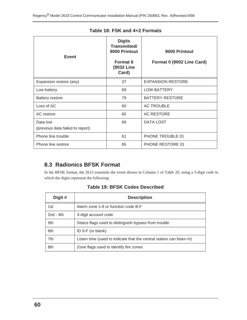
Regency® Model 2615 Control Communicator Installation Manual (P/N 150863, Rev. A)Revised 8/98
60
8.3 Radionics BFSK FormatIn the BFSK format, the 2615 transmits the event shown in Column 1 of Table 20, using a 5-digit code in
which the digits represent the following:
Expansion restore (any) 37 EXPANSION RESTORE
Low battery 69 LOW BATTERY
Battery restore 79 BATTERY RESTORE
Loss of AC 60 AC TROUBLE
AC restore 60 AC RESTORE
Data lost
(previous data failed to report)
69 DATA LOST
Phone line trouble 61 PHONE TROUBLE 01
Phone line restore 65 PHONE RESTORE 01
Table 19: BFSK Codes Described
Digit # Description
1st Alarm zone 1-8 or function code B-F
2nd - 4th 3-digit account code
5th Status flags used to distinguish bypass from trouble
6th ID 0-F (or blank)
7th Listen time (used to indicate that the central station can listen in)
8th Zone flags used to identify fire zones
Table 18: FSK and 4+2 Formats
Event
Digits Transmitted/ 9000 Printout
Format 6 (9032 Line
Card)
9000 Printout
Format 0 (9002 Line Card)
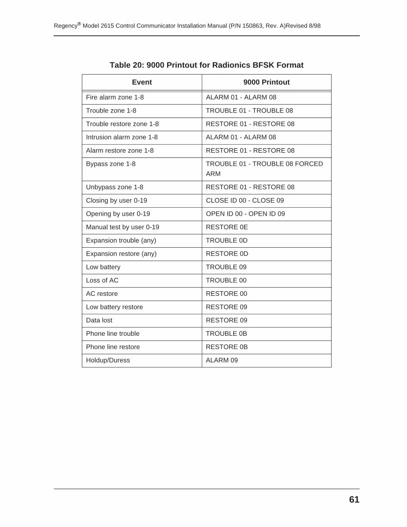
61
Regency® Model 2615 Control Communicator Installation Manual (P/N 150863, Rev. A)Revised 8/98
Table 20: 9000 Printout for Radionics BFSK Format
Event 9000 Printout
Fire alarm zone 1-8 ALARM 01 - ALARM 08
Trouble zone 1-8 TROUBLE 01 - TROUBLE 08
Trouble restore zone 1-8 RESTORE 01 - RESTORE 08
Intrusion alarm zone 1-8 ALARM 01 - ALARM 08
Alarm restore zone 1-8 RESTORE 01 - RESTORE 08
Bypass zone 1-8 TROUBLE 01 - TROUBLE 08 FORCED
ARM
Unbypass zone 1-8 RESTORE 01 - RESTORE 08
Closing by user 0-19 CLOSE ID 00 - CLOSE 09
Opening by user 0-19 OPEN ID 00 - OPEN ID 09
Manual test by user 0-19 RESTORE 0E
Expansion trouble (any) TROUBLE 0D
Expansion restore (any) RESTORE 0D
Low battery TROUBLE 09
Loss of AC TROUBLE 00
AC restore RESTORE 00
Low battery restore RESTORE 09
Data lost RESTORE 09
Phone line trouble TROUBLE 0B
Phone line restore RESTORE 0B
Holdup/Duress ALARM 09

Regency® Model 2615 Control Communicator Installation Manual (P/N 150863, Rev. A)Revised 8/98
62
REGENCY® ONE YEAR LIMITED WARRANTY
Interactive Technologies, Inc. (ITI) warrants that Regency products manufactured by ITI(Regency Product) will be free from defects in material and workmanship for one (1) yearfrom the date of purchase by the original purchaser.
This Limited Warranty extends only to the original purchaser and does not extend to con-sumers, end users or other secondary purchasers of Regency Product. Consumers orend users should contact their selling dealer as to the nature and extent of the dealer'swarranty, if any.
ITI's obligation under this Limited Warranty is limited to the repair or replacement, at ITI’soption, of any defective Regency Product at no additional charge. ITI reserves the right toreplace Regency Product under this Limited Warranty with new or remanufactured prod-uct. ITI will not be responsible for labor costs of removal or reinstallation of RegencyProduct. The repaired or replaced Regency Product is then warranted under the terms ofthis Limited Warranty for the balance of the term of this Limited Warranty or for ninety(90) days, whichever is longer.
This Limited Warranty does not cover the ITI PC-based software products or batteries ofany type used in connection with Regency Product (please refer to the battery manufac-turer’s warranty, if any).
ITI is not responsible for conditions or applications over which ITI has no control. Defectsor problems as a result of such conditions or applications are not the responsibility of ITI.Such conditions or applications include normal wear and tear, catastrophe, fault or negli-gence of the user or the original purchaser, improper installation, application, mainte-nance or use of Regency Product, or other causes external to Regency Product.
If you have a warranty claim, please contact Customer Service at 1-800-777-4841 andrequest authorization to return the Regency Product. Customer Service will issue you aReturn Merchandise Authorization (RMA) number. Return the Regency Product, freightprepaid, to ITI together with reference to the RMA number and a written explanation set-ting forth the potential defect in reasonable detail.
THE ORIGINAL PURCHASER'S EXCLUSIVE REMEDY WITH RESPECT TO ANY AND ALLLOSSES OR DAMAGES RESULTING FROM ANY CAUSE WHATSOEVER SHALL BEREPAIR OR REPLACEMENT, AS SPECIFIED ABOVE. ITI SHALL IN NO EVENT BE LIABLEFOR ANY CONSEQUENTIAL OR INCIDENTAL DAMAGES, HOWEVER OCCASIONED,WHETHER BY NEGLIGENCE OR OTHERWISE. SOME STATES DO NOT ALLOW THEEXCLUSION OR LIMITATION OF INCIDENTAL OR CONSEQUENTIAL DAMAGES, SO THISLIMITATION OR EXCLUSION MAY NOT APPLY TO YOU.
THE FOREGOING LIMITED WARRANTY IS IN LIEU OF ALL OTHER WARRANTIES,EXPRESS OR IMPLIED, AND NO PERSON (INCLUDING ANY AGENT, DEALER OR REP-RESENTATIVE OF ITI) IS AUTHORIZED TO MAKE ANY REPRESENTATION OR WAR-RANTY CONCERNING REGENCY PRODUCT EXCEPT TO REFER ORIGINALPURCHASERS TO THIS LIMITED WARRANTY. ANY IMPLIED WARRANTIES (INCLUDING,WITHOUT LIMITATION, ANY IMPLIED WARRANTIES OF MERCHANTABILITY OR FIT-NESS FOR A PARTICULAR PURPOSE) ARE LIMITED TO THE DURATION OF THIS LIM-ITED WARRANTY. SOME STATES DO NOT ALLOW LIMITATIONS ON HOW LONG ANIMPLIED WARRANTY LASTS, SO THIS LIMITATION MAY NOT APPLY TO YOU.
THIS LIMITED WARRANTY GIVES YOU SPECIFIC LEGAL RIGHTS. YOU MAY ALSO HAVEOTHER RIGHTS WHICH VARY FROM STATE TO STATE.
Interactive Technologies, Inc. * 2266 Second Street North * North St. Paul, Minnesota 55109 Rev 10/97 - 466-1537
Regency® Model 2615 Control Communicator Installation Manual (P/N 150863, Rev. A) Revised 8/98
63
Index
Symbols# key . . . . . . . . . . . . . . . . . . . . . . . . . . . . . .50# of supervised touchpads option. . . . . . . . . . . .36# Rings option . . . . . . . . . . . . . . . . . . . . . . . .47* key . . . . . . . . . . . . . . . . . . . . . . . . . . .26, 50
Numerics24-Hour Alarm option. . . . . . . . . . . . . . . . .5, 4324-Hour Trouble option. . . . . . . . . . . . . . . . . .4324-hour zones. . . . . . . . . . . . . . . . . . . . . . . . .352608 Auxiliary Relays. . . . . . . . . . . . . . . . . . .182608 Ground Start Relays. . . . . . . . . . . .1, 10, 182615 Control Communicator. . . . . . . . . . . . . . .102-Second Pause option. . . . . . . . . . . . . . . . . . .504+2 formats. . . . . . . . . . . . . . . . . . . . . . . . . .594180 Status Display Modules
as compatible accessories. . . . . . . . . . . . . . .1calculating current draw for . . . . . . . . . . . .10installing. . . . . . . . . . . . . . . . . . . . . . . . .19options for. . . . . . . . . . . . . . . . . . . . . . . .33see also Status Display Modules
4650 LED Touchpads . . . . . . . . . . .1, 10, 24, 384660 Series LCD Touchpads. . . . . . . . . . . . .2, 104660R LED Touchpads . . . . . . . . . . . . . . . . . .246712 12 VDC Rechargeable Battery. . . . . . . . . .157628 4.7K ohm end-of-line resistor . . . . . . . . . .429000 Digital Alarm Receiver. . . . . . . . . . . . . . .569004I SIA Line Card. . . . . . . . . . . . . . . . . . . .56
AAC Input terminal. . . . . . . . . . . . . . . . . . . . . . .8AC Loss Hours option. . . . . . . . . . . . . . . . . . .47AC power switch . . . . . . . . . . . . . . . . . . . . . . .8AC restore event. . . . . . . . . . . . . . . . . . . .60, 61AC RESTORE printout . . . . . . . . . . . . . . .57, 60AC TROUBLE printout. . . . . . . . . . . . . . .57, 60accessible wire runs. . . . . . . . . . . . . . . . . . . . . .8accessories . . . . . . . . . . . . . . . . . . . . . . . . . . .1Accessory Ground (-) terminal . . . . . . . . . . . . . .8Accessory Power (+) terminal. . . . . . . . . . . . . . .8Account #1 option. . . . . . . . . . . . . . . . . . . . . .50Account #2 option. . . . . . . . . . . . . . . . . . . . . .50
acknowledgment tones. . . . . . . . . . . . . . . . . . 56agency requirements . . . . . . . . . . . . . . . . . . . . 4ALARM 01 - ALARM 08 printout. . . . . . . 59, 61ALARM 09 printout . . . . . . . . . . . . . . . . . . . 61ALARM 11 - ALARM 18 printout. . . . . . . . . . 59alarm current . . . . . . . . . . . . . . . . . . . . . . . . 10alarm delayed. . . . . . . . . . . . . . . . . . . . . . . . 38alarm receivers
see digital alarm receiversAlarm Report Delay option. . . . . . . . . . . . . . . 45Alarm reset by user # event. . . . . . . . . . . . . . . 57ALARM RESTORE 01 printout. . . . . . . . . . . . 59ALARM RESTORE 10 printout. . . . . . . . . . . . 59ALARM RESTORE 11 - 18 printout. . . . . . . . . 59ALARM RESTORE 11 -18 printout. . . . . . . . . 59Alarm restore zone # . . . . . . . . . . . . . . . . . . . 58Alarm restore zone 1-8 event. . . . . . . . . . . 59, 61alarm tones . . . . . . . . . . . . . . . . . . . . . . . . . 22Alarm zone # event . . . . . . . . . . . . . . . . . . . . 58alarms
audible type . . . . . . . . . . . . . . . . . . . . . . 38audio response to. . . . . . . . . . . . . . . . . . . 38described. . . . . . . . . . . . . . . . . . . . . . . . 20priority ratings for. . . . . . . . . . . . . . . . . . 23restoring . . . . . . . . . . . . . . . . . . . . . . . . 58shutdown. . . . . . . . . . . . . . . . . . . . . . . . 38Steps 1 through 8. . . . . . . . . . . . . . . . . . . 36tones, described . . . . . . . . . . . . . . . . . . . 23
All Primary option. . . . . . . . . . . . . . . . . . . . . 35Answer Ring option. . . . . . . . . . . . . . . . . . . . 46AR 0 digits. . . . . . . . . . . . . . . . . . . . . . . . . . 57Arm Lock Interior Key option . . . . . . . . . . . 5, 33ARMED LED. . . . . . . . . . . . . . . . . . . . . . . . 29Armed status . . . . . . . . . . . . . . . . . . . . . . . . 20ASCII characters. . . . . . . . . . . . . . . . . . . . . . 57AT 0 digits. . . . . . . . . . . . . . . . . . . . . . . . . . 57Attempts/Reporting format for Phone Number #1 op-tion. . . . . . . . . . . . . . . . . . . . . . . . . . . . . . . 51Attempts/Reporting Format for Phone Number #2 op-tion. . . . . . . . . . . . . . . . . . . . . . . . . . . . . . . 52audible alarms . . . . . . . . . . . . . . . . . . . . . . . 38Audible Pre-Alarm option. . . . . . . . . . . . . . . . 34
see also Cross Alarm option
Regency® Model 2615 Control Communicator Installation Manual (P/N 150863, Rev. A) Revised 8/98
64
audible signalssee signals
Auto Bypass option. . . . . . . . . . . . . . . . . . . . .35Auto Interior option. . . . . . . . . . . . . . . . . . . . .33Auto Test . . . . . . . . . . . . . . . . . . . . .28, 57, 59AUTO TEST printout . . . . . . . . . . . . . . . . . . .57Auto Test Time . . . . . . . . . . . . . . . . . . . . . . .26Auto Unbypass option. . . . . . . . . . . . . . . . . . .35automatic shutdown. . . . . . . . . . . . . . . . . . . . .39AUX key. . . . . . . . . . . . . . . . . . . . . .25, 41, 57auxiliary alarms . . . . . . . . . . . . . . . . . . . .20, 23Auxiliary LED . . . . . . . . . . . . . . . . . . . . .29, 38Auxiliary panic key
see AUX keyAuxiliary Relay Contacts terminals . . . . . . . . . . .8auxiliary relays
state of . . . . . . . . . . . . . . . . . . . . . . . . . .23Steps 1 through 8 . . . . . . . . . . . . . . . . . . .36telephone networks and . . . . . . . . . . . . . . .18
auxiliary zones. . . . . . . . . . . . . . . . . . . . . . . .39AWG
see wiring
Bbackup power. . . . . . . . . . . . . . . . . . . . . . . . .15battery
low power. . . . . . . . . . . . . . . . . . . . . . . .60rechargeable type . . . . . . . . . . . . . . . . . . .15restoring power . . . . . . . . . . . . . . . . . . . .61
battery cables. . . . . . . . . . . . . . . . . . . . . . . . . .7Battery restore event . . . . . . . . . . . . . . . . . . . .60BATTERY RESTORE printout. . . . . . . . . .57, 60BATTERY TROUBLE printout. . . . . . . . . . . . .57beeps
codes and . . . . . . . . . . . . . . . . . . . . . . . .37error type . . . . . . . . . . . . . . . . . . . . . . . .26see also Exit Beeps option
Bell Output option . . . . . . . . . . . . . . . . . . . . .53Bell Shutdown option . . . . . . . . . . . . . . . . .6, 44Bell Test @ Arm option. . . . . . . . . . . . . . . . . .32Bell Test @ Reset option . . . . . . . . . . . . . . . . .32Bell Type and Cadence option. . . . . . . . . . . . . .53Bell/Touchpad Test mode. . . . . . . . . . . . . .27, 28bells, wiring. . . . . . . . . . . . . . . . . . . . . . . . . .14BFSK format. . . . . . . . . . . . . . . . . . .56, 60, 61BFSK14 format . . . . . . . . . . . . . . . . . . . . . . .56BFSK23 format . . . . . . . . . . . . . . . . . . . . . . .56boards
see circuit boards
burglary alarmssee also intrusion alarms
burglary zones . . . . . . . . . . . . . . . . . . . . 11, 58bus devices . . . . . . . . . . . . . . . . . . . . . . . . . 54buttons
see also function keysBypass Code option. . . . . . . . . . . . . . . . . . . . 35Bypass option
see Swinger Bypass optionBypass restore zone 1-8 event . . . . . . . . . . . . . 59Bypass zone # event. . . . . . . . . . . . . . . . . . . . 58Bypass zone 1-8 event . . . . . . . . . . . . . . . 59, 61Bypassable option. . . . . . . . . . . . . . . . . . . . . 44bypassing
24-hour zones. . . . . . . . . . . . . . . . . . . . . 43status flags. . . . . . . . . . . . . . . . . . . . . . . 60zones . . . . . . . . . . . . . . . . . . . . . . . 35, 49
BYPS key . . . . . . . . . . . . . . . . . . . . 25, 29, 39
CCA38A telephone jack. . . . . . . . . . . . . . . . 4, 18cables
battery type . . . . . . . . . . . . . . . . . . . . . . . 7length required for touchpads. . . . . . . . . . . 16
Cadence option. . . . . . . . . . . . . . . . . . . . . . . 53calculating
current draw. . . . . . . . . . . . . . . . . . . . . . 10wire runs. . . . . . . . . . . . . . . . . . . . . . . . 17
central station. . . . . . . . . . . . . . . . . . . . . 28, 48CF 0-19 digits. . . . . . . . . . . . . . . . . . . . . . . . 57changing, instant zones. . . . . . . . . . . . . . . . . . 33Chime option . . . . . . . . . . . . . . . . . . . . . . . . 44chime tones . . . . . . . . . . . . . . . . . . . 20, 23, 36chime zone closed zone . . . . . . . . . . . . . . . . . 22chime zone opened tone . . . . . . . . . . . . . . . . . 22CHM key. . . . . . . . . . . . . . . . . . . . . . . . 25, 44circuit boards . . . . . . . . . . . . . . . . . . . . . . 7, 20circuits, short
see short circuitsCL 0-19 digits . . . . . . . . . . . . . . . . . . . . . . . 57Close by user # event. . . . . . . . . . . . . . . . . . . 57CLOSE ID 00 - CLOSE 09 printout . . . . . . . . . 61CLOSE ID 00 - CLOSE ID 09 printout . . . . . . . 59CLOSE ID 0-19 printout. . . . . . . . . . . . . . . . . 57Closing by user 0-19 event . . . . . . . . . . . . 59, 61CLR key . . . . . . . . . . . . . . . . . . . . . . . . . . . 25Code 0 . . . . . . . . . . . . . . . . . . . . . . . . . . . . 37
see also Maintenance Code
Regency® Model 2615 Control Communicator Installation Manual (P/N 150863, Rev. A) Revised 8/98
65
Code 1. . . . . . . . . . . . . . . . . . . . . . . . . . . . . 37see also Main User Code
CODE 2 key. . . . . . . . . . . . . . . . . . . . . . . . . 25CODE 2 LED . . . . . . . . . . . . . . . . . . . . . . . . 29codes
2 through 19. . . . . . . . . . . . . . . . . . . . . . 37bypass code option and. . . . . . . . . . . . . . . 35Code 0. . . . . . . . . . . . . . . . . . . . . . . . . . 37Code 1. . . . . . . . . . . . . . . . . . . . . . . . . . 37Main User’s Code . . . . . . . . . . . . . . . . . . 37secret
see secret codescoin telephones . . . . . . . . . . . . . . . . . . . . . . . . 4cold zones . . . . . . . . . . . . . . . . . . . . . . . 39, 58Computer Account # option. . . . . . . . . . . . . . . 50Computer Phone # option . . . . . . . . . . . . . . . . 50connecting
6712 battery to the 2615 . . . . . . . . . . . . . . 159220 to the 2615 . . . . . . . . . . . . . . . . . . . 14the Supervised Siren Module . . . . . . . . . . . . 6
connectionsdescribed for 4180. . . . . . . . . . . . . . . . . . 20for ground start network relays. . . . . . . . . . 19for telephone lines . . . . . . . . . . . . . . . . . . 18LED D7 and. . . . . . . . . . . . . . . . . . . . . . . 7
control communicator. . . . . . . . . . . . . . . . . . . 10Control trouble event . . . . . . . . . . . . . . . . . . . 57correcting
errors. . . . . . . . . . . . . . . . . . . . . . . . . . . 30interference. . . . . . . . . . . . . . . . . . . . . . . . 4
Cross Alarm Delay option. . . . . . . . . . . . . 34, 45Cross Alarm Zones 3 & 4 option. . . . . . . . . . . . 34Cross Pre-alarm tone . . . . . . . . . . . . . . . . . . . 22current draw . . . . . . . . . . . . . . . . . . . . . . . . . 16Current Draw Worksheet. . . . . . . . . . . . . . . 9, 10currents
electrical requirements . . . . . . . . . . . . . . . . 3overcurrent protection. . . . . . . . . . . . . . . . . 7
Customer Service. . . . . . . . . . . . . . . . . . . . . . 62
DD23 LED. . . . . . . . . . . . . . . . . . . . . . . . . . . . 7D7 LED. . . . . . . . . . . . . . . . . . . . . . . . . . . . . 7D8 LED. . . . . . . . . . . . . . . . . . . . . . . . . . . . . 7Daily Auto Test option . . . . . . . . . . . . . . . . . . 32Daily Tests. . . . . . . . . . . . . . . . . . . . . . . . . . 26daisy chaining. . . . . . . . . . . . . . . . . . . . . . . . 16data lost. . . . . . . . . . . . . . . . . . . . . . 55, 60, 61DATA LOST 0 printout . . . . . . . . . . . . . . . . . 57
DATA LOST printout. . . . . . . . . . . . . . . . . . . 60data, entering. . . . . . . . . . . . . . . . . . . . . . . . . 30Day Trouble option. . . . . . . . . . . . . . . . . . . . . 43Day Trouble zones . . . . . . . . . . . . . . . . . . . . . 11Default Close option. . . . . . . . . . . . . . . . . . . . 32default, codes . . . . . . . . . . . . . . . . . . . . . . . . 37Delayed Bypass Report option . . . . . . . . . . . . . 35delayed zones . . . . . . . . . . . . . . . . . . . . . . . . 33delays, smoke verification . . . . . . . . . . . . . . . . 52descriptions, system . . . . . . . . . . . . . . . . . . . . . 1detectors
passive infrared . . . . . . . . . . . . . . . . . . . . 34smoke, see smoke detectors
devicescalculating current draw for . . . . . . . . . . . . 10installing. . . . . . . . . . . . . . . . . . . . . . . . . . 7overcurrent type. . . . . . . . . . . . . . . . . . . . . 7repairing. . . . . . . . . . . . . . . . . . . . . . . . . . 4see also signaling devicestesting . . . . . . . . . . . . . . . . . . . . . . . . . . 28
Dialer failed . . . . . . . . . . . . . . . . . . . . . . . . . 55Dialer Test mode . . . . . . . . . . . . . . . . . . . 27, 28dialer, programming . . . . . . . . . . . . . . . . . . . . 54digital alarm receiver . . . . . . . . . . . . . . . . . . . 56digits
see Duress Trigger Digits optionDirect line for Account #1 option . . . . . . . . . . . 52Direct line for Account #2 option . . . . . . . . . . . 52disabling, panic keys. . . . . . . . . . . . . . . . . . . . 41disarming the system. . . . . . . . . . . 33, 36, 39, 49DLY key . . . . . . . . . . . . . . . . . . . . . . . . 25, 33DOOR key . . . . . . . . . . . . . . . . . . . . . . . . . . 26doorbell tones . . . . . . . . . . . . . . . . . . . . . 22, 36doorbell zones. . . . . . . . . . . . . . . . . . . . . . . . 39downloading . . . . . . . . . . . . . . . . 28, 29, 47, 53driver, siren
see siren driverdriver, speaker
see speaker driversduress alarms. . . . . . . . . . . . . . . . 20, 23, 36, 57Duress feature . . . . . . . . . . . . . . . . . . . . . . . . 37Duress Trigger Digits option. . . . . . . . . . . . 36, 37duress/holdup event . . . . . . . . . . . . . . . . . . . . 61
EEarth Ground terminal. . . . . . . . . . . . . . . . . . . . 8EEPROMs . . . . . . . . . . . . . . . . . . . . . . . . . . 57

Regency® Model 2615 Control Communicator Installation Manual (P/N 150863, Rev. A) Revised 8/98
66
electricalratings . . . . . . . . . . . . . . . . . . . . . . . . . . .8requirements . . . . . . . . . . . . . . . . . . . . . . .3shocks . . . . . . . . . . . . . . . . . . . . . . . . . . .7
EMERGENCY ALARM 82 printout . . . . . . . . .57emergency alarms. . . . . . . . . . . . . . . . . . .20, 23emergency zones . . . . . . . . . . . . . . . . . . .39, 58end-of-line (EOL) resistors. . . . . . . . . . .5, 42, 54entering data . . . . . . . . . . . . . . . . . . . . . . . . .30Entry Delay 1 option. . . . . . . . . . . . . . . . .44, 45Entry Delay 2 option. . . . . . . . . . . . . . . . .44, 45entry delays. . . . . . . . . . . . . . . . . . . . . . . .6, 36entry warning tones. . . . . . . . . . . . . . . . . . . . .22environmental specifications. . . . . . . . . . . . . . . .3equivalence, ringer . . . . . . . . . . . . . . . . . . . . . .4ER 17-19 digits . . . . . . . . . . . . . . . . . . . . . . .57error beeps. . . . . . . . . . . . . . . . . . . . . . . . . . .26errors
common types . . . . . . . . . . . . . . . . . . . . .54correcting . . . . . . . . . . . . . . . . . . . . . . . .30
ESL Model 499CT smoke detector. . . . . . . . . . .12ET 17-19 digits. . . . . . . . . . . . . . . . . . . . . . . .57ET 7 digits. . . . . . . . . . . . . . . . . . . . . . . . . . .57ET 8 digits. . . . . . . . . . . . . . . . . . . . . . . . . . .57Exit Beeps option . . . . . . . . . . . . . . . . . . . . . .32Exit Delay option . . . . . . . . . . . . . . . . . . . . . .44exit delays
auxiliary relays and. . . . . . . . . . . . . . . . . .36disabling. . . . . . . . . . . . . . . . . . . . . . . . .33length of . . . . . . . . . . . . . . . . . . . . . . . . . .6
exit warning tones. . . . . . . . . . . . . . . . . . . . . .22exiting programming mode. . . . . . . . . . . . . . . .30Expansion restore (any) event . . . . . . . . . . .60, 61EXPANSION RESTORE 17-19 printout. . . . . . .57EXPANSION RESTORE printout . . . . . . . . . . .60Expansion trouble (any) event. . . . . . . . . . .59, 61EXPANSION TROUBLE 17-19 printout . . . . . .57EXPANSION TROUBLE 7 printout. . . . . . . . . .57EXPANSION TROUBLE 8 printout. . . . . . . . . .57EXPANSION TROUBLE printout. . . . . . . . . . .59external, siren driver . . . . . . . . . . . . . . . . . . . .13
FFA 81 digits. . . . . . . . . . . . . . . . . . . . . . . . . .57Fail Attempts option . . . . . . . . . . . . . . . . . . . .46failed to report . . . . . . . . . . . . . . . . . . . . . . . .60failures
of the system . . . . . . . . . . . . . . . . . . . . . .54power. . . . . . . . . . . . . . . . . . . . .47, 60, 61
Fast Response option. . . . . . . . . . . . . . . . . . . 43Fast Restores option. . . . . . . . . . . . . . . . . . . . 32FCC
registration number . . . . . . . . . . . . . . . . . . 4warning. . . . . . . . . . . . . . . . . . . . . . . . . . 4
FCC Part 15. . . . . . . . . . . . . . . . . . . . . . . . . i, 4FIC number . . . . . . . . . . . . . . . . . . . . . . . . . . 4FIRE ALARM 81 printout . . . . . . . . . . . . . . . 57Fire alarm zone 1-8 event . . . . . . . . . . . . . 59, 61fire alarms . . . . . . . . . . . . . . . . . . . . 20, 23, 36FIRE key. . . . . . . . . . . . . . . . . . . . . 25, 41, 57fire panic key
see FIRE keyfire zones. . . . . . . . . . . . . . . . 5, 11, 39, 58, 60flags, status and zone type. . . . . . . . . . . . . . . . 60Force Arm option . . . . . . . . . . . . . . . . . . . 5, 35Forced close by user # event . . . . . . . . . . . . . . 57FORCED CLOSE ID. . . . . . . . . . . . . . . . . . . 33FORCED CLOSE ID 0-19 printout. . . . . . . . . . 57Forced Close Report option. . . . . . . . . . . . . . . 33FSK format . . . . . . . . . . . . . . . . . . . . . . . . . 59FSK81 format. . . . . . . . . . . . . . . . . . . . . . . . 56function keys . . . . . . . . . . . . . . . . . . . . . 25, 29
Ggauge, wire . . . . . . . . . . . . . . . . . . . . . . . . . 16Ground Start option. . . . . . . . . . . . . . . . . . . . 45ground start relays
as a compatible accessory. . . . . . . . . . . . . . 1calculating current draw for. . . . . . . . . . . . 10illustration of . . . . . . . . . . . . . . . . . . . . . 19telephone networks and . . . . . . . . . . . . . . 18
ground start telephone networks. . . . . . . . . . . . . 4guidelines, mounting . . . . . . . . . . . . . . . . . . . . 8
HHA 0 digits . . . . . . . . . . . . . . . . . . . . . . . . . 57harmful interference. . . . . . . . . . . . . . . . . . . . . 4heat zones . . . . . . . . . . . . . . . . . . . . . . . 39, 58HOLDUP ALARM printout . . . . . . . . . . . . . . 57holdup alarms. . . . . . . . . . . . . . . . . . 20, 23, 36holdup zones . . . . . . . . . . . . . . . . . . . . . 39, 58Holdup/Duress event . . . . . . . . . . . . . . . . . . . 61humidity . . . . . . . . . . . . . . . . . . . . . . . . . . . . 3
IICOM key . . . . . . . . . . . . . . . . . . . . . . . . . . 26ID 0-F. . . . . . . . . . . . . . . . . . . . . . . . . . . . . 60
Regency® Model 2615 Control Communicator Installation Manual (P/N 150863, Rev. A) Revised 8/98
67
incorrect connections . . . . . . . . . . . . . . . . . . . . 7indoor use. . . . . . . . . . . . . . . . . . . . . . . . . . . . 3information, entering . . . . . . . . . . . . . . . . . . . 30inputs, power requirements for. . . . . . . . . . . . . . 3Installer Operations Quick Reference table. . . . . 28installing
accessories. . . . . . . . . . . . . . . . . . . . . . . . 7control panels . . . . . . . . . . . . . . . . . . . . . . 7status display modules . . . . . . . . . . . . . . . 19touchpads. . . . . . . . . . . . . . . . . . . . . 15, 16
Instant if Alarm option . . . . . . . . . . . . . . . . . . 34instant zones. . . . . . . . . . . . . . . . . . . . . . . . . 33INT key . . . . . . . . . . . . . . . . . . . . . . 25, 33, 43Interactive Technologies, Inc.
see ITIinterference. . . . . . . . . . . . . . . . . . . . . . . . . . . 4Interior LED. . . . . . . . . . . . . . . . . . . . . . 29, 42Interior Off @ Disarm option. . . . . . . . . . . . . . 34Interior On @ Intrusion Alarm option . . . . . . . . 33Interior Zones option . . . . . . . . . . 33, 34, 43, 44Intrusion alarm zone 1-8 event . . . . . . . . . . 59, 61intrusion alarms. . . . . . . . . . . . . . 20, 23, 36, 59intrusion zones . . . . . . . . . . . . . . . . . . . . . . . 39ITI
address . . . . . . . . . . . . . . . . . . . . . . . . . . 4Order Entry (sales). . . . . . . . . . . . . . . . . . . 1Technical Support . . . . . . . . . . . . . . . . . . . 1
Jjack. . . . . . . . . . . . . . . . . . . . . . . . . . . . . . . 18jacks, telephone. . . . . . . . . . . . . . . . . . . . . . . . 4
see also telephones, jacksjumping to a step. . . . . . . . . . . . . . . . . . . . . . 30
Kkeys
described . . . . . . . . . . . . . . . . . . . . . . . . 29mechanical. . . . . . . . . . . . . . . . . . . . . . . . 6see function keys
Llatching, 24-hour zones and. . . . . . . . . . . . . . . 43Layout. . . . . . . . . . . . . . . . . . . . . . . . . . . . . 20LCDs. . . . . . . . . . . . . . . . . . . . . . . . . . . . . . 50LED Driver option. . . . . . . . . . . . . . . . . . . . . 19LED touchpads . . . . . . . . . . . . . . . . . . 1, 10, 24LEDs
D23. . . . . . . . . . . . . . . . . . . . . . . . . . . . . 7
D7. . . . . . . . . . . . . . . . . . . . . . . . . . . . . . 7D8. . . . . . . . . . . . . . . . . . . . . . . . . . . . . . 7described . . . . . . . . . . . . . . . . . . . . . . . . 29programming. . . . . . . . . . . . . . . . . . . . . . 29
limited warranty. . . . . . . . . . . . . . . . . . . . . . . 62line cards . . . . . . . . . . . . . . . . . . . . . . . . . . . 56line resistance . . . . . . . . . . . . . . . . . . . . . . . . . 8line voltage. . . . . . . . . . . . . . . . . . . . . . . . . . . 3listen time. . . . . . . . . . . . . . . . . . . . . . . . . . . 60local auxiliary zones. . . . . . . . . . . . . . . . . . . . 39location of panel. . . . . . . . . . . . . . . . . . . . . . . . 8Loss of AC event . . . . . . . . . . . . . . . . . . . 60, 61Low AC event. . . . . . . . . . . . . . . . . . . . . . . . 57Low battery event. . . . . . . . . . . . . 55, 57, 60, 61LOW BATTERY printout . . . . . . . . . . . . . . . . 60Low battery restore event. . . . . . . . . . . . . . . . . 61
Mmain drop runs. . . . . . . . . . . . . . . . . . . . . . . . . 8Main User’s Code. . . . . . . . . . . . . . . . . . . . . . 37
see also Code 1Maintenance Code . . . . . . . . . . . . . . . . . . . . . 37
see also Code 0Manual test by user # event . . . . . . . . . . . . . . . 57Manual test by user 0-19 event . . . . . . . . . . . . . 61MANUAL TEST ID 0-19 printout. . . . . . . . . . . 57Manual test or Auto test event. . . . . . . . . . . . . . 59manufacturer (ITI) . . . . . . . . . . . . . . . . . . . . . . 4mechanical keys. . . . . . . . . . . . . . . . . . . . . 6, 39MEM key . . . . . . . . . . . . . . . . . . . . . 25, 29, 30Memory trouble event. . . . . . . . . . . . . . . . . . . 57mistakes, correcting . . . . . . . . . . . . . . . . . . . . 30model number . . . . . . . . . . . . . . . . . . . . . . . . . 4modes
see Dialer Test modesee Programming modesee Touchpad/Bell Test modesee Walk Test mode
modulesinstalling. . . . . . . . . . . . . . . . . . . . . . . 7, 19Regency Supervised Siren module. . . . . . . . . 5see also status display module
mountingthe 2615. . . . . . . . . . . . . . . . . . . . . . . . . . 8touchpads. . . . . . . . . . . . . . . . . . . . . 15, 16
Must report to #1 option . . . . . . . . . . . . . . . . . 47Must report to #2 option . . . . . . . . . . . . . . . . . 47MUTE key . . . . . . . . . . . . . . . . . . . . 25, 29, 43MUTED . . . . . . . . . . . . . . . . . . . . . . . . . . . . 54
Regency® Model 2615 Control Communicator Installation Manual (P/N 150863, Rev. A) Revised 8/98
68
NN.C.
see normally closedN.O.
see normally opennetwork, telephone types . . . . . . . . . . . . . . .4, 18no alarm shutdown . . . . . . . . . . . . . . . . . . . . .38No Alarm zones . . . . . . . . . . . . . . . . . . . . . . .39No Delay LED. . . . . . . . . . . . . . . . . .29, 33, 34non-corrosive. . . . . . . . . . . . . . . . . . . . . . . . . .3non-medical alarms. . . . . . . . . . . . . . . . . . . . .20Normally Closed Contacts option. . . . . . . . . . . .42normally closed zones . . . . . . . . . . . . . . . . . . .11normally open contacts . . . . . . . . . . . . . . . . .5, 8Normally Open Contacts option. . . . . . . . . . . . .42normally open zones . . . . . . . . . . . . . . . . . . . .11Not Bypassable option. . . . . . . . . . . . . . . . . . . .5notices, FCC . . . . . . . . . . . . . . . . . . . . . . . . . . i
OOP 0-19 digits . . . . . . . . . . . . . . . . . . . . . . . .57Open by user # event. . . . . . . . . . . . . . . . . . . .57OPEN ID 00 - OPEN ID 09 printout. . . . . . .59, 61OPEN ID 0-19 printout . . . . . . . . . . . . . . . . . .57OPEN REST ID 0-19 printout. . . . . . . . . . . . . .57Opening by user 0-19 event . . . . . . . . . . . .59, 61operations reference table. . . . . . . . . . . . . . . . .28options
described. . . . . . . . . . . . . . . . . . . . . . . . .38programming. . . . . . . . . . . . . . . .29, 31, 32Step 9. . . . . . . . . . . . . . . . . . . . . . . . . . .40Steps 10 through 18. . . . . . . . . . . . . . . . . .42Steps 19 through 20. . . . . . . . . . . . . . . . . .50Steps 21 through 26. . . . . . . . . . . . . . . . . .51UL requirements and. . . . . . . . . . . . . . . . . .5
OR 0-19 digits . . . . . . . . . . . . . . . . . . . . . . . .57Order Entry (Sales). . . . . . . . . . . . . . . . . . . . . .1outputs
alarm tones for. . . . . . . . . . . . . . . . . . . . .23of speakers . . . . . . . . . . . . . . . . . . . . . . .38power requirements for . . . . . . . . . . . . . . . .3
overcurrent devices. . . . . . . . . . . . . . . . . . . . . .7overcurrent protection . . . . . . . . . . . . . . . . . . . .7overloading . . . . . . . . . . . . . . . . . . . . . . . . . . .7
PP3 Pin. . . . . . . . . . . . . . . . . . . . . . . . . . . . . .20PA 83 digits. . . . . . . . . . . . . . . . . . . . . . . . . .57
PANIC ALARM 83 printout . . . . . . . . . . . . . . 57panic alarms. . . . . . . . . . . . . . . . . . . . . . 20, 23panic keys
disabling . . . . . . . . . . . . . . . . . . . . . . . . 39programming Step 9.9 to 9.11 . . . . . . . . . . 41see also POL key, FIRE key, AUX key
panic zones . . . . . . . . . . . . . . . . . . . . . . 39, 58Part 15 . . . . . . . . . . . . . . . . . . . . . . . . . . . . i, 4party line telephones . . . . . . . . . . . . . . . . . . . . 4passive infrared detectors
see PIR detectorsPhone #1 option . . . . . . . . . . . . . . . . . . . . . . 50Phone #2 option . . . . . . . . . . . . . . . . . . . . . . 50Phone line restore . . . . . . . . . . . . . . . . . . . . . 61phone line restore . . . . . . . . . . . . . . . . . . . . . 60Phone line trouble. . . . . . . . . . . . . . . . . . . . . 61phone line trouble . . . . . . . . . . . . . . . . . . 55, 60PHONE RESTORE 01 printout . . . . . . . . . . . . 60PHONE TROUBLE 01 printout. . . . . . . . . . . . 60phones
see telephonesPIR (passive infrared) detectors . . . . . . . . . . . . 34POL key . . . . . . . . . . . . . . . . . . . . . 25, 41, 57police panic key
see POL keypower
backup . . . . . . . . . . . . . . . . . . . . . . . . . 15restoring . . . . . . . . . . . . . . . . . . . . . 60, 61
power failure . . . . . . . . . . . . . . . 15, 47, 60, 61Power LED . . . . . . . . . . . . . . . . . . . . . . 54, 55power switches. . . . . . . . . . . . . . . . . . . . . . . . 8power transformers . . . . . . . . . . . . . . . . . . . . 14Previous (lost) data failed to report event. . . . . . 57priority rating, alarms. . . . . . . . . . . . . . . . . . . 23programmable options . . . . . . . . . . . . . . . . . . 31programming
alarm response . . . . . . . . . . . . . . . . . . . . 38beeps while . . . . . . . . . . . . . . . . . . . . . . 37mistakes . . . . . . . . . . . . . . . . . . . . . . . . 37options . . . . . . . . . . . . . . . . . . . . . . . . . 29seeing what step you are on. . . . . . . . . . . . 30Step 9 . . . . . . . . . . . . . . . . . . . . . . . 38, 40Steps 1 through 8. . . . . . . . . . . . . . . . . . . 32Steps 10 through 18. . . . . . . . . . . . . . . . . 42Steps 19 through 20. . . . . . . . . . . . . . . . . 50Steps 21 through 26. . . . . . . . . . . . . . . . . 51the panel . . . . . . . . . . . . . . . . . . . . . . . . 29with active dialer. . . . . . . . . . . . . . . . . . . 54zones . . . . . . . . . . . . . . . . . . . . . . . . . . 38
programming mode . . . . . . . . . . . . . . . . . 28, 30
Regency® Model 2615 Control Communicator Installation Manual (P/N 150863, Rev. A) Revised 8/98
69
QQA 82 digits. . . . . . . . . . . . . . . . . . . . . . . . . 57quick reference table. . . . . . . . . . . . . . . . . . . . 28
Rradio communications, problems with . . . . . . . . . 4radio frequency (RF) . . . . . . . . . . . . . . . . . . . . 4Radionics BFSK format . . . . . . . . . . . 56, 60, 61ratings, electrical . . . . . . . . . . . . . . . . . . . . . . . 8READY LED . . . . . . . . . . . . . . . . . . . . . . . . 29rechargeable batteries. . . . . . . . . . . . . . . . . . . 15Regency Supervised Siren Module . . . . . . . . . . . 5registration number (FCC). . . . . . . . . . . . . . . . . 4relays
auxiliary. . . . . . . . . . . . . . . . . . . . . . . . . 18ground start network type . . . . . . . . . . . . . 19see also auxiliarysee also ground start
repairing . . . . . . . . . . . . . . . . . . . . . . . . . . . . 4Report Alarm to #1 option. . . . . . . . . . . . . . . . 48Report Alarm to #2 option. . . . . . . . . . . . . . . . 49Report Bypass to #1 option . . . . . . . . . . . . . . . 48Report Bypass to #2 option . . . . . . . . . . . . . . . 49report delayed. . . . . . . . . . . . . . . . . . . . . . . . 38Report Open Reset option . . . . . . . . . . . . . 48, 49Report Open/Close to #1 option . . . . . . . . . . . . 48Report Open/Close to #2 option . . . . . . . . . . . . 49Report Open-Reset to #1 option . . . . . . . . . . . . 48Report Open-Reset to #2 option . . . . . . . . . . . . 49Report Restores to #1 option . . . . . . . . . . . . . . 48Report Restores to #2 option . . . . . . . . . . . . . . 49Report Tests to #1 option. . . . . . . . . . . . . . . . . 48Report Tests to #2 option. . . . . . . . . . . . . . . . . 49Report Trouble to #1 option. . . . . . . . . . . . . . . 48Report Trouble to #2 option. . . . . . . . . . . . . . . 49report, data failed to. . . . . . . . . . . . . . . . . . . . 60reporting formats. . . . . . . . . . . . . . . . . . . . . . 56reprints, ordering. . . . . . . . . . . . . . . . . . . . . . . 1requirements
agency. . . . . . . . . . . . . . . . . . . . . . . . . . . 4electrical . . . . . . . . . . . . . . . . . . . . . . . . . 3FCC . . . . . . . . . . . . . . . . . . . . . . . . . . . . 4telephone . . . . . . . . . . . . . . . . . . . . . . . . . 4touchpads. . . . . . . . . . . . . . . . . . . . . . . . 16UL . . . . . . . . . . . . . . . . . . . . . . . . . . . . . 5
resettingcross alarms . . . . . . . . . . . . . . . . . . . . . . 28dialers . . . . . . . . . . . . . . . . . . . . . . . . . . 28smoke detectors. . . . . . . . . . . . . . . . . . . . 28
residential use of panel . . . . . . . . . . . . . . . . . . . 4resistance, line. . . . . . . . . . . . . . . . . . . . . . . . . 8resistors . . . . . . . . . . . . . . . . . . . . . . . 5, 42, 54Restore (alarm or trouble) event . . . . . . . . . . . . 58RESTORE 00 printout. . . . . . . . . . . . . . . . . . . 61RESTORE 01 - RESTORE 08 printout. . . . . 59, 61RESTORE 09 printout. . . . . . . . . . . . . . . . . . . 61RESTORE 0B printout . . . . . . . . . . . . . . . . . . 61RESTORE 0D printout . . . . . . . . . . . . . . . . . . 61RESTORE 0E printout . . . . . . . . . . . . . . . . . . 61Restore AC event. . . . . . . . . . . . . . . . . . . . . . 57Restore battery event. . . . . . . . . . . . . . . . . . . . 57restored zones . . . . . . . . . . . . . . . . . . . . . . . . 49restores
AC power. . . . . . . . . . . . . . . . . . . . . . . . 60any type of . . . . . . . . . . . . . . . . . . . . . . . 60battery . . . . . . . . . . . . . . . . . . . . . . . 60, 61expansion. . . . . . . . . . . . . . . . . . . . . . . . 61panic keys and. . . . . . . . . . . . . . . . . . . . . 41phone line. . . . . . . . . . . . . . . . . . . . . . . . 60power. . . . . . . . . . . . . . . . . . . . . . . . . . . 61see Fast Restores option
Retry if Fail option. . . . . . . . . . . . . . . . . . . . . 45ring detectors. . . . . . . . . . . . . . . . . . . . . . . . . 54ringer equivalence . . . . . . . . . . . . . . . . . . . . . . 4RJ38X telephone jack . . . . . . . . . . . . . . . . . 4, 18RP 0 digits . . . . . . . . . . . . . . . . . . . . . . . . . . 57RT 0 digits . . . . . . . . . . . . . . . . . . . . . . . . . . 57RX 0-19 digits. . . . . . . . . . . . . . . . . . . . . . . . 57
SSAI20 format. . . . . . . . . . . . . . . . . . . . . . . . . 56SAI8 format . . . . . . . . . . . . . . . . . . . . . . . . . 56Sales (Order Entry). . . . . . . . . . . . . . . . . . . . . . 1secret codes. . . . . . . . . . . . . . . . . . . . . . . . . . 37Security Industry Association standard
see SIASerial Data In (to Touchpads) terminal. . . . . . . . . 8Serial Data Out (to Touchpads) terminal. . . . . . . . 8service, customer . . . . . . . . . . . . . . . . . . . . . . 62servicing devices . . . . . . . . . . . . . . . . . . . . . . . 4setting
Auto Test Time . . . . . . . . . . . . . . . . . . . . 26touchpad ID numbers . . . . . . . . . . . . . . . . 17
shocks, electrical . . . . . . . . . . . . . . . . . . . . . . . 7short circuits . . . . . . . . . . . . . . . . . . . . . . . 7, 54SHUNTED 10 printout . . . . . . . . . . . . . . . . . . 59SHUNTED 11 - 18 printout . . . . . . . . . . . . . . . 59shutdown, automatic. . . . . . . . . . . . . . . . . . . . 39
Regency® Model 2615 Control Communicator Installation Manual (P/N 150863, Rev. A) Revised 8/98
70
SIA format . . . . . . . . . . . . . . . . . . . . . . .56, 57SIA20 format. . . . . . . . . . . . . . . . . . . . . . . . .57SIA8 format. . . . . . . . . . . . . . . . . . . . . . . . . .57SIC number. . . . . . . . . . . . . . . . . . . . . . . . . . .4signaling devices
calculating current draw for . . . . . . . . . . . .10testing. . . . . . . . . . . . . . . . . . . . . . . . . . .28wiring. . . . . . . . . . . . . . . . . . . . . . . . . . .13
Signals . . . . . . . . . . . . . . . . . . . . . . . . . . . . .22signals, described . . . . . . . . . . . . . . . . . . . . . .22Silent Alarm Report . . . . . . . . . . . . . . . . . . . .36silent alarms. . . . . . . . . . . . . . . . . . . . . . .22, 38Silent Night Trouble option. . . . . . . . . . . . . .5, 32siren drivers. . . . . . . . . . . . . . . . . . . . . . . . . .13sirens . . . . . . . . . . . . . . . . . . . . . . . . . . . . . . .5SK4+2 format . . . . . . . . . . . . . . . . . . . . . . . .56Smoke Detector Ground (-) terminal. . . . . . . . . . .8Smoke Detector Power (+) terminal . . . . . . . . . . .8smoke detectors
calculating current for . . . . . . . . . . . . . . . .10installing. . . . . . . . . . . . . . . . . . . . . . . . . .7wiring. . . . . . . . . . . . . . . . . . . . . . . . . . .12
Smoke Verify option. . . . . . . . . . . . . . . . . . . .52Smoke Verify Time option. . . . . . . . . . . . . . . .52speaker drivers. . . . . . . . . . . . . . . . . . . . . . . .13Speaker Ground terminal . . . . . . . . . . . . . . . . . .8Speaker Power (+) terminal. . . . . . . . . . . . . . . . .8speakers
alarm tones . . . . . . . . . . . . . . . . . . . . . . .23output from . . . . . . . . . . . . . . . . . . . . . . .38wiring. . . . . . . . . . . . . . . . . . . . . . . . . . .13
special alarms. . . . . . . . . . . . . . . . . . . . . .20, 23specifications
agencies . . . . . . . . . . . . . . . . . . . . . . . . . .4electrical. . . . . . . . . . . . . . . . . . . . . . . . . .3environmental . . . . . . . . . . . . . . . . . . . . . .3touchpads . . . . . . . . . . . . . . . . . . . . . . . .16
sprinkler zones. . . . . . . . . . . . . . . . . . . . .39, 58standby current. . . . . . . . . . . . . . . . . . . . . . . .10STAT key . . . . . . . . . . . . . . . . . . . . .25, 29, 30Status Display Modules
accessories . . . . . . . . . . . . . . . . . . . . . . . .1calculating current for . . . . . . . . . . . . . . . .10connectors for . . . . . . . . . . . . . . . . . . . . .20installing. . . . . . . . . . . . . . . . . . . . . . . . .19options for. . . . . . . . . . . . . . . . . . . . . . . .33typical applications of . . . . . . . . . . . . . . . .21
status flags. . . . . . . . . . . . . . . . . . . . . . . . . . .60Step 9. . . . . . . . . . . . . . . . . . . . . . . . . . . . . .40Step Programming mode . . . . . . . . . . . . . .28, 29
steps, moving (jumping) to . . . . . . . . . . . . . . . 30Store OP/CL option. . . . . . . . . . . . . . . . . . . . 46sub-steps, moving (jumping) to . . . . . . . . . . . . 30Supervised option (24-Hour or Day Trouble) . . . 43supervised siren modules . . . . . . . . . . . . . . . . . 5supervised zones. . . . . . . . . . . . . . . . . . . . . . 11support, technical . . . . . . . . . . . . . . . . . . . . . . 1Swinger Bypass option. . . . . . . . . . . . . 5, 35, 45Swinger Window option. . . . . . . . . . . . . . . . . 45switches, power . . . . . . . . . . . . . . . . . . . . . . . 8system description. . . . . . . . . . . . . . . . . . . . . . 1system troubles. . . . . . . . . . . . . . . . . . . . 23, 55
Ttamper alarms. . . . . . . . . . . . . . . . . . . . . . . . 36
see also intrusion alarmstamper zones . . . . . . . . . . . . . . . . . . . . . 39, 58Technical Support. . . . . . . . . . . . . . . . . . . . . . 1Technologies . . . . . . . . . . . . . . . . . . . . . . . . . 4TEL key . . . . . . . . . . . . . . . . . . . . . . . . . . . 26Telephone . . . . . . . . . . . . . . . . . . . . . . . . . . . 4telephone company . . . . . . . . . . . . . . . . . . . . . 4telephone number, ITI . . . . . . . . . . . . . . . . . . . 1telephones
busy lines. . . . . . . . . . . . . . . . . . . . . . . . 43coin type . . . . . . . . . . . . . . . . . . . . . . . . . 4ground start networks. . . . . . . . . . . . . . 4, 18jack types. . . . . . . . . . . . . . . . . . . . . . 4, 18line connections . . . . . . . . . . . . . . . . . . . 18party line services . . . . . . . . . . . . . . . . . . . 4requirements. . . . . . . . . . . . . . . . . . . . . . . 4see also phonetrouble conditions . . . . . . . . . . . . . . . . . . 43
temperature range . . . . . . . . . . . . . . . . . . . . . . 3temporal-three siren. . . . . . . . . . . . . . . . . . . . . 5terminal strips. . . . . . . . . . . . . . . . . . . . . . . . . 8terminal voltages. . . . . . . . . . . . . . . . . . . . . . 54TEST HRS mode . . . . . . . . . . . . . . . . . . . . . 39TEST key . . . . . . . . . . . . . . . . . . . . . . . 25, 30TEST printout. . . . . . . . . . . . . . . . . . . . . . . . 59tests, setting times for. . . . . . . . . . . . . . . . . . . 26time-out of program mode warning. . . . . . . . . . 22tones
acknowledgment type. . . . . . . . . . . . . . . . 56described. . . . . . . . . . . . . . . . . . . . . . . . 22
Total Attempts option . . . . . . . . . . . . . . . . . . 46Total Standby Current . . . . . . . . . . . . . . . . . . 10Touchpad 1 trouble . . . . . . . . . . . . . . . . . . . . 55Touchpad 2 trouble . . . . . . . . . . . . . . . . . . . . 55
Regency® Model 2615 Control Communicator Installation Manual (P/N 150863, Rev. A) Revised 8/98
71
Touchpad 3 trouble . . . . . . . . . . . . . . . . . . . . 55Touchpad Ground (-) terminal . . . . . . . . . . . . . . 8Touchpad Power (+) terminal. . . . . . . . . . . . . . . 8Touchpad restore 1-3 event . . . . . . . . . . . . . . . 57Touchpad trouble 1-3 event . . . . . . . . . . . . . . . 57Touchpad/Bell Test mode . . . . . . . . . . . . . 27, 28touchpads. . . . . . . . . . . . . . . . . . . . . . . . . . . 10
basic operation . . . . . . . . . . . . . . . . . . . . 24cable length for . . . . . . . . . . . . . . . . . . . . 16daisy chaining. . . . . . . . . . . . . . . . . . . . . 16installation . . . . . . . . . . . . . . . . . . . . 15, 16keystroke tones . . . . . . . . . . . . . . . . . . . . 22LCD type. . . . . . . . . . . . . . . . . . . . . . 2, 54LED type. . . . . . . . . . . . . . . . 1, 24, 38, 54maximum per system . . . . . . . . . . . . . . . . 16number supervised. . . . . . . . . . . . . . . . . . 36operation . . . . . . . . . . . . . . . . . . . . . . . . 29see also LCD touchpadssee also LED touchpadssetting ID numbers for . . . . . . . . . . . . . . . 17specifications . . . . . . . . . . . . . . . . . . . . . 16testing . . . . . . . . . . . . . . . . . . . . . . . . . . 28trouble with . . . . . . . . . . . . . . . . . . . . . . 54UL requirements and . . . . . . . . . . . . . . . . . 6wiring . . . . . . . . . . . . . . . . . . . . . . . . . . 16
TouchTone Phone Used option. . . . . . . . . . . . . 47transformers . . . . . . . . . . . . . . . . . . . . . . . . . 14trigger digits
see Duress Trigger Digits optionTROUBLE. . . . . . . . . . . . . . . . . . . . . . . 54, 55TROUBLE 00 printout . . . . . . . . . . . . . . . . . . 61TROUBLE 01 - TROUBLE 08 FORCED printout61TROUBLE 01 - TROUBLE 08 printout. . . . 59, 61TROUBLE 01 printout . . . . . . . . . . . . . . . . . . 59TROUBLE 09 printout . . . . . . . . . . . . . . . . . . 61TROUBLE 0B printout. . . . . . . . . . . . . . . . . . 61TROUBLE 0D printout. . . . . . . . . . . . . . . . . . 61trouble alarms. . . . . . . . . . . . . . . . . . . . . . . . 20trouble conditions
auxiliary relay and. . . . . . . . . . . . . . . . . . 36repairing . . . . . . . . . . . . . . . . . . . . . . . . 43viewing . . . . . . . . . . . . . . . . . . . . . . . . . 54
trouble event. . . . . . . . . . . . . . . . . . . . . . . . . 59Trouble restore zone # event . . . . . . . . . . . . . . 58Trouble restore zone 1-8 event . . . . . . . . . . 59, 61trouble tones. . . . . . . . . . . . . . . . . . . . . . . . . 22trouble tones option . . . . . . . . . . . . . . . . . . . . 32Trouble zone # event . . . . . . . . . . . . . . . . . . . 58Trouble zone 1-8 event. . . . . . . . . . . . . . . 59, 61troubles
expansion type. . . . . . . . . . . . . . . . . . . . . 61phone line. . . . . . . . . . . . . . . . . . . . . 60, 61restoring. . . . . . . . . . . . . . . . . . . . . . . . . 58see also system troublesstatus flags and . . . . . . . . . . . . . . . . . . . . 60supervised. . . . . . . . . . . . . . . . . . . . . . . . 43
troubleshooting . . . . . . . . . . . . . . . . . . . . . . . 54typing, data. . . . . . . . . . . . . . . . . . . . . . . . . . 30typos, correcting. . . . . . . . . . . . . . . . . . . . . . . 30
UUL
Fire Zones. . . . . . . . . . . . . . . . . . . . . . . . . 5requirements . . . . . . . . . . . 5, 11, 44, 45, 46
UL Listed. . . . . . . . . . . . . . . . . . . . . . . . . . . 18Unbypass zone # event . . . . . . . . . . . . . . . . . . 58Unbypass zone 1-8 event. . . . . . . . . . . . . . 59, 61undefined zones. . . . . . . . . . . . . . . . . . . . 39, 58Up/Downloading Used option. . . . . . . . . . . . . . 46Use TouchTone phone only option . . . . . . . . . . 47use, residential. . . . . . . . . . . . . . . . . . . . . . . . . 4User Code Programming mode. . . . . . . . . . . . . 39
Vvoltage drops. . . . . . . . . . . . . . . . . . . . . . 16, 17voltage, line . . . . . . . . . . . . . . . . . . . . . . . . . . 3voltages, terminal. . . . . . . . . . . . . . . . . . . . . . 54voltameter. . . . . . . . . . . . . . . . . . . . . . . . . . . 54
WWait for Second Dial Tone option. . . . . . . . . . . 50Walk Test mode. . . . . . . . . . . . . . . . . 27, 28, 39warning tones . . . . . . . . . . . . . . . . . . . . . . . . 22warnings
FCC requirements and. . . . . . . . . . . . . . . . . 4see also entry warning and exit warning
warranty. . . . . . . . . . . . . . . . . . . . . . . . . . . . 62water zones. . . . . . . . . . . . . . . . . . . . . . . 39, 58Weekly Auto Test option. . . . . . . . . . . . . . . . . 32Weekly Tests. . . . . . . . . . . . . . . . . . . . . . . . . 26windows, cross-alarms and. . . . . . . . . . . . . . . . 34wiring
AC power transformers. . . . . . . . . . . . . . . 14accessible wiring runs. . . . . . . . . . . . . . . . . 8bells. . . . . . . . . . . . . . . . . . . . . . . . . . . . 14calculating wire runs. . . . . . . . . . . . . . . . . 17line resistance . . . . . . . . . . . . . . . . . . . . . . 8minimum wire gauge . . . . . . . . . . . . . . . . 16
Regency® Model 2615 Control Communicator Installation Manual (P/N 150863, Rev. A) Revised 8/98
72
overloading and short circuits . . . . . . . . . . . .7signaling devices . . . . . . . . . . . . . . . . . . .13siren driver . . . . . . . . . . . . . . . . . . . . . . .13smoke detectors . . . . . . . . . . . . . . . . . . . .12speakers . . . . . . . . . . . . . . . . . . . . . . . . .13touchpads . . . . . . . . . . . . . . . . . . . . . . . .16zones . . . . . . . . . . . . . . . . . . . . . . . . . . .11
Worksheet, Current Draw. . . . . . . . . . . . . . .9, 10
YYR 0 digits . . . . . . . . . . . . . . . . . . . . . . . . . .57YT 0 digits . . . . . . . . . . . . . . . . . . . . . . . . . .57
ZZone #1 Options. . . . . . . . . . . . . . . . . . . . . . .40Zone #2 Options. . . . . . . . . . . . . . . . . . . . . . .40Zone #3 Options. . . . . . . . . . . . . . . . . . . . . . .40Zone #4 Options. . . . . . . . . . . . . . . . . . . . . . .40Zone #5 Options. . . . . . . . . . . . . . . . . . . . . . .40Zone #6 Options. . . . . . . . . . . . . . . . . . . . . . .40Zone #7 Options. . . . . . . . . . . . . . . . . . . . . . .40Zone #8 Options. . . . . . . . . . . . . . . . . . . . . . .41Zone 1 Input terminal . . . . . . . . . . . . . . . . . . . .9Zone 2 Input terminal . . . . . . . . . . . . . . . . . . . .9Zone 3 Input terminal . . . . . . . . . . . . . . . . . . . .9Zone 4 Input terminal . . . . . . . . . . . . . . . . . . . .9Zone 5 Input terminal . . . . . . . . . . . . . . . . . . . .9Zone 6 Input terminal . . . . . . . . . . . . . . . . . . . .9Zone 7 Input terminal . . . . . . . . . . . . . . . . . . . .9Zone 8 Input terminal . . . . . . . . . . . . . . . . . . . .9zone display activated tones . . . . . . . . . . . . . . .22zone flags . . . . . . . . . . . . . . . . . . . . . . . . . . .60Zone LED. . . . . . . . . . . . . . . . . . . . . . . .29, 54zone troubles . . . . . . . . . . . . . . . . . . . . . .22, 54zones
24-hour type . . . . . . . . . . . . . . . . . . . . . .35bypassing . . . . . . . . . . . . . . . . . .35, 44, 49delays and. . . . . . . . . . . . . . . . . . . . .33, 44disabling. . . . . . . . . . . . . . . . . . . . . . . . .39fire type . . . . . . . . . . . . . . . . . . . . . . . . . .5instant. . . . . . . . . . . . . . . . . . . . . . . . . . .33interior option . . . . . . . . . . . . . . . . . .33, 34options . . . . . . . . . . . . . . . . . . . . . . . . . .38programming. . . . . . . . . . . . . . . . . . . . . .38restored. . . . . . . . . . . . . . . . . . . . . . . . . .49viewing. . . . . . . . . . . . . . . . . . . . . . . . . .54wiring. . . . . . . . . . . . . . . . . . . . . . . . . . .11
Zones 1 and 2 Power Output terminal. . . . . . . . . .9
Zones 3 and 4 Power Output terminal . . . . . . . . . 9Zones 5 and 6 Power Output terminal . . . . . . . . . 9Zones 7 and 8 Power Output terminal . . . . . . . . . 9