Embed Size (px)
Citation preview

* .
Ii
;iu
; sl
~~~~~AItA3 s tn D'? g
Ln0
UO-'-4;:X
S- *o i n -:'3 ,- r ,~2
D + t~ U-1
"'i ~ ~ ~ :
(vl
(t~~~~~
'4 01 tz2x,
~~3d C,0U'
Cr t; r3 , -icL () UT O O trl
I-J~, '-!.
* Fj *L, zr-
/S,n~ .
,C : L
iD~~~L
'~;U
\UL 3t
·,, r, ,
4:?
I s,
. td .
** * r>*¢*,,, ,+~~~~~~~~~~.,%
·s
, /
. ,¢
.r-i"~~~~.
t~lA5RLESSTA i S 02139
ts 2;S) tt.itn ¢ ..................... i'r~
C'A;P-,FI-'iSDE MIASeSAC-itUSET'l
0. S¢77
6:.I: i $'piirA ;,.'
iI
,,i: P FU ,
GIU g DAM'Cp HA IGNN
AMD COMTM'6 L'-
'%77 '" '- ' ? ::' -
f., .... ' r ::." - " i
.A~..x'?'; .1 $ 1 1'
https://ntrs.nasa.gov/search.jsp?R=19720025987 2019-08-18T10:53:15+00:00Z

h0 _
..Z
M. H. HAMILTON, IR., MISSION PROGRAM DEVEL.APOLLO GUIDANCE AND NAVIGATION PROGRAM
Approved: Date: Zlc.'7f
S. L. COPPS, COLOSSUS PROJECT MANAGERAPOLLO GUIDANCE AND NAVIGATION PROGRAM
Approved: Date:
R. H. BATTIN, DIRECTOR, MISSION DEVELOPMENTAPOLLO GUIDANCE AND NAVIGATION PROGRAM
g ~~-Approved: ~({Date: i VIo-T 7!;;,Qia D. G. HOAG, DIRE(R f /
APOLLO GUIDANCE AND NtGATION PROGRAM
LSJ Approved: a Date:-Saty
R. R. RAGAN.TDEPIt DIRECTOR-R-577v CHARLES STARK DRAPER LABORATORY
GUIDANCE SYSTEM OPERATIONS PLANFOR MANNED CM EARTH ORBITAL AND
LUNAR MISSIONS USINGPROGRAM COLOSSUS 3
SECTION 2 DATA LINKS(Rev. 15)
NOVEMBER. 1971
Ell 7V CHARLES STA-RK t -A TCAMBRIDGE, MASSACHUSETTS, 02139 t A02139AM L Aa&A
I.1

ACKNO\V LEDGEM:ENT
This report was prepared under DSR Project 55-23890, sponsored by the Manned
Spacecraft Center of the National Aeronautics and Space Administration through
Contract NAS 9-4065.
ii

R-577
GUIDANCE SYSTEM OPERATIONS PLAN
FOR MANNED CM EARTH ORBITAL AND
LUNAR MISSIONS USING
PROGRAM COLOSSUS
SECTION 2 DATA LINKS
REVISION 15
Signatures appearing on this page designate
approval of this document by NASA/MSC.
Approved:John RC.arma? /aSection Chief, Guidance Program SectionManned Spacecraft Center, NASA
Approved: ZL-,• _ e&-e_'__^John, ;Williams, Jr.Chief; Simulation and Flight Softwa re BranchManned Spacecraft Center N SA
Approved: /James/ Stokes, Jr.Chief, `F ight Support DivisionManne dSpacecraft Center, NASA
Date: /.
Date: /6 ¢7/
Date: "'i /2/2
iii

1.p--' )G~ PAG1 BLANKi NOT i0i' Li¥r,Bi-:iF~{3!!D~ ,(5 ..VI J_ , r~~~~~~~~~~~~~~~~~~~~~~~~~~~~~~~~~Date: 10 June 1968
REVISION INDEX COVER SHEET
GUIDANCE SYSTEM OPERATIONS PLAN
GSOP # R-577 Title: For Manned CM Earth Orbital and Lunar MissionsUsing Program COLOSSUS
Section #2 Title: Data Links (Revision 1)
This publication, a complete new revision (Rev. 1), incorporates revisionsand additions as indicated below:
Revision 1
PCR- (PCN)
PCR- 154
PCR- 157
PCR- 172(MIT-101)*
PCR- 174(MIT- 108)*
PCR-422(MIT- 146)*
PCN-417*
Description of Change
Update GSOP, Section 2, for typing errors,scaling changes, extra detail and description.
Lambert target updates conform to verb 71 format.
Change word-order of Entry/Update list.
LANDMARK I. D. added to P22 downlist.
Words 20 and 33 of the Entry/Update list wereinterchanged. Word 100 of the same list is nowGAMMA (EI) and Range for Initialization.
Use of ENDSAFE terminated.
Because of the numerous changes required by PCR #154 in Revision 1,there will be no PCR/PCN reference information at the bottom of anypage which changed as a result of PCR #154 only.
Additional UPLINK information resulted in the following new sections:
2,1.5
2.1.5.1
2.1.5.2
2.1.5.3
2.1.5. 4
2.1.5.5
2.1.5.6
2.1.5.7
Use of the Contiguous Block Update Verb.
CMC CSM/LM State Vector Update.
CMC Desired REFSMMAT Update.
CMC External DELTA V Update.
CMC Retrofire External DELTA V Update.
CMC Entry Update.
CMC Lambert Target Update.
CMC Lambert Return to Earth Update.
Preceding page blank Av
*Indicates an MIT Program Change Notice (PCN)

Date: November 1968
REVISION INDEX COVER SHEET
GUIDANCE SYSTEM OPERATIONS PLAN
GSOP # R-577
Section # 2
Title: For Manned CM Earth Orbital and Lunar Missions
Using Program COLOSSUS 1 (Rev 237)
Title: Data Links (Revision 2)
This publication, a complete new revision (Rev 2), is expanded in many places
over the previous one (Rev 1, dated June 1968). Only changes in specifications,
resulting from the PCR/PCN information listed below, will be indicated by a
solid-black line at the edge of the page along with the appropriate reference
number at the bottom of the page. Any editorial changes will be marked by a
vertical series of black dots at the page's edge.
PCR/PCN Description of Change
PCR 439.1*'
PCR 237
PCN 585*
Deleted logic in P52 to check status of preferred orientationflag. It is not required now in the Preferred REFSMMATUpdate.
Update GSOP, Section 2 Rev 1, for typing errors, scalingchanges additions and revisions.
Scaling in word 27b (Rend/Pre) should be changed to,"multiply by 18.52".
FAILREG +2 may also contain a first digit of 1 or 5.
Delete word "RESTART", IMODES 30, bit 7.
* Indicates an MIT Program Change Notice (PCN).
Note: PCR 207. 1 was complied with in Revision 2 but was not indicated in the list
above.
vi

Date: March 1969
REVISION INDEX COVER SHEET
GUIDANCE SYSTEM OPERATIONS PLAN
GSOP #R-577
Section #2
Title: For Manned CM Earth Orbital and Lunar Missions
Using Program COLQSSUS 2 - COMANCHE(Rev 44& 45)
Title: Data Links (Revision 3)
This publication, a complete new revision (Rev. 3), is expanded in many
plazes over the previous one (Rev. 2, dated November 1968). Only changes in
specifications, resulting from the PCR/PCN information listed below, will be
indicated by a solid black line at the edge of the page along with the appropriate
reference number at the bottom of the page. Any editorial changes will be
marked by a vertical series of black dots at the page's edge.
PCR/PCN
PCR 250
PCR 256
PCR 266
PCR 269**
PCR 606
PCN 627. 1
PCR 656
PCN 662*
PCN 667*
PCN 678*
PCN 685*
PCN 689*
PCR 690
PCR 691
PCN 693*
PCR 711
PCR 735
PCN 746
Description of Change
Put MI into erasable.
Eliminates R35 and fixed memory lunar landmarks.
Makes CSI/CDH data available on downlinks andcorrects downlink addresses for R30 data.
Changes to Section 2 COLOSSUS GSOP (Rev. 2).
Eliminates R60FLAG.
Eliminates NTARGFLG.
Uprated TVC DAP.
Deletes V67FLAG.
Creates flagbit, AMOONFLG.
Creates flagbit, V96ONFLG.
Creates flagbit, NODOPO1.
Creates flagbit, SKIPVHF,
Creates flagbit, SLOWFLG.
Creates flagbit, RETROFLG.
Creates flagbit, P21FLAG.
Issue SIV-B cutoff.
Place P11 on Powered List. Replace DELTAR withPACTOFF, YACTOFF on Coast and Align List.
Entry Roll Error on Downlist.
Indicates an MIT Program Change Notice (PCN).
NOTE: Due to its magnitude, PCR 269 will not be written as a reference numberat the bottom of a page when the change pertains only to PCR 269.
vii'

Date: June 1969
REVISION INDEX COVER SHEETGUIDANCE SYSTEM OPERATIONS PLAN
GSOP # R-577 Title: For Manned CM Earth Orbital and Lunar Missions UsingProgram COLOSSUS 2 (MANCHE 45, Rev. 2)
Section #2 Title: Data Links (Revision 4)
This complete, new revision (Rev. 4), updates the previous publication
(Rev. 3, dated March 1969) and incorporates the NASA/MSC approved
change listed below.
PCR and PCN changes are indicated by denoting the applicable number
at the bottom of the page and by marking the location of the change with a
solid black line at the edge of the page. Editorial corrections (not covered
by PCR) are denoted by a vertical series of black dots.
PCR DESCRIPTION OF CHANGE
Changes to COLOSSUIS 2 (COMANCHE, Rev. 45)
Section 2, Rev. 3.
viii

Date: June 1969
REVISION INDEX COVER SHEETGUIDANCE SYSTEM OPERATIONS PLAN
GSOP # R-577
Section ft 2
Title: For Manned CM Earth Orbital and Lunar Missions UsingProgram COLOSSUS 2A (COMANCHE, Rev. 55)
Title: Data Links (Revision 5)
This publication, Rev. 5, is a supplement to the previous issue Rev. 4,
dated June 1969, and incorporates PCR #275 described below. The supplement-
ary pages are printed on tinted stock and marked 2A. When these tinted pages
are included the document is a valid COLOSSUS 2A(COMANCHE, Rev. 55)
configuration.
PCR DESCRIPTION OF CHANGE
275 Change RCSselected rate from4 0 /sec. to 2 /sec.
ix

Date: July 1 969
REVISION INDEX COVER SHEET
GUIDANCE SYSTEM OPERATIONS PLAN
GSOP #R-577
Section #2
Title: For Manned CM Earth Orbital and Lunar Missions UsingProgram COLOSSUS 2C (Comanche, Rev. 67 )
Title: Data Links (Revision 6)
This publication, a complete new revision (Rev. 6) incorporates
revisions as indicated below:
PCR/PCN
PCR 278
PCR 815
PCN 833*
PCR 787
PCR 802.1
PCR 785
DESCRIPTION OF CHANGE
Fixed DUMPCNT
Digital Autopilot Barbecue Mode Routine
SWTOVER Check
Make N63 Count during P61.
Save Alarm Data after "Error Reset"
Reverse V50N18 Logic in P20
NOTE: PCR 268. 1, which should have been reflected in Rev. 5, wasinadvertently overlooked at that time. It was processed inRev. 6 (page 2-42)
*Indicates an MIT Program Change Notice (PCN).
x

Date: September 1969
REVISION INDEX COVER SHEET
GUIDANCE SYSTEM OPERATIONS PLAN
GSOP #R-577 Title: For Manned CM Earth Orbital and Lunar MissionsUsing Program COLOSSUS 2C (Comanche, Rev. 67)
Section #2 Title: Data Links (Revision 7)
This publication, a complete new revision (Rev. 7) incorporates
revisions as indicated below:
PCR/PCN
PCR 791. 1
PCR 798. 1'
PCR 801. i
DESCRIPTION OF CHANGE
Do not allow Proceed response to V21,
V22, V23
Reset GLOKFAIL in ROO
Make BAILOUT alarms 3xxxx, POODOO
alarms 2xxxx
Yaw DAP CDU sampling
Remove restriction of R05 only in P00
Change Recycle point on N63 in P61
Resetting and setting of XDELVFLG
PCR 810
'PCR 832. 1
PCN 835*
PCR 812. 1
*Indicates an MIT Program Change Notice (PCN).
xi

Date: November 1969
REVISION INDEX COVER SHEET
GUIDANCE SYSTEM OPERATIONS PLAN
GSOP No. R-577
Section 'No. 2
Title: For Manned CM Earth Orbital and Lunar MissionsUsing Program COLOSSUS 2D (COMANCHE, Rev. 72)
Title: Data Links (Rev. 8)
This publication, a complete new revision (Rev. 8)
incorporates revisions as indicated below:
PCR/ PCN
PCR 863.1
PCR 963
PCR
'PCN
PCR
966
965
961
DESCRIPTION OF CHANGE
Make P76 set NODO flag
In R52 delete program alarm 407 and drive
trunnion to 500 if desired trunnion > 500
Clearing Preferred Orientation Flag
Define POOFLAG
SIVB-TB6 E-Memory Routine
Indicates an MIT Program Change Notice (PCN).
xii

Date: December 1969
REVISION INDEX COVER SHEET
GUIDANCE SYSTEM OPERATIONS PLAN
GSOP No. R-577
Section No. 2
Title: For Manned CM Earth Orbital and Lunar MissionsUsing Program COLOSSUS 2D (MANCHE72, Rev. 3)
Title: Data Links (Rev. 9)
Attached are change-pages for, and a supplement page to,
Section 2 Data Links of R-577 Guidance System Operations
Plan for Manned CM Earth Orbital and Lunar Missions
using Program COLOSSUS 2D.
The substitution of the white change-pages and the addition
of the supplemental page in Rev. 8 (November 1969)
will update this document to a COLOSSUS 2D (MANCHE72,
Rev. 3) configuration.
PCR/PCN
PCR 984
PCN 992*
DESCRIPTION OF CHANGE
Avoid Coarse Align During Saturn
T6JOB OPCODE Correction
-Indicates an MIT Program Change Notice (PCN)
xiii
C.

Date: March 1970
REVISION INDEX COVER SI-EET
GUIDANCE SYSTEM OPERATIONS PLAN
GSOP No. R-577
Section No. 2
Title: For Manned CM Earth Orbital and LunarMissions Using Program COLOSSUS 2E
Title: Data Links (Revision 10)
This publication, a complete new revision, incorporates the NASA/MSC approvedchanges, listed below.
PCR(PC N )
292
295
868
0 869
916
917
921
956
973
978
985
987
991. 1
993
994'
1002*
TITLE
Add Time Display to V79
AK's on Powered Downlist
P23 Changes§
Rate Aided Optics Drive
Delete P17 and P77
Delete P31
N38 and N06 on Downlist
Time of Longitude
Move T6JOB to Fixed Memory
Check OPTMODES Bit 3 when V37 Requested
Delete P38, P39 and P78, P79
Rate-Aided Optics (P24)
Sum Uplink Data
P23 Auto Maneuver Change
Elimination of Bit 1 of OPTMODES
GSOP Section 2 Rev 10 Editorial Changes
§ Additional material added in Revision 12.
xiv
0To

Date: June 1970
REVISION INDEX COVER SHEET
GUIDANCE SYSTEM OPERATIONS PLAN
GSOP No. R-577
Section No. 2
Title: For Manned CM Earth Orbital and LunarMissions Using Program COLOSSUS 2E
Title: Data Links (Revision 11)
Revision 11 incorporates the following NASA/MSC approved changes and becomesthe control document for COLOSSUS 2E (Revision 108).
TITLE
Channel 77
Channel 77
Check ENGONFLG, not SPS ENGON outbit
Deletion of Time of Longitude (P29)
Change Time to Perform IMUCDUZero
GSOP Section 2 Rev 11 Editorial Changes
xv
PCR(PCN'')
302.1
315. 1
995".
1034
1046 '
1053*

Date: October 1970
REVISION INDEX COVER SHEET
GUIDANCE SYSTEM OPERATIONS PLAN
GSOP No. R-577 Title: For Manned CM Earth Orbital andLunar Missions Using ProgramCOLOSSUS 2E
Section No. 2 Title: Data Links (Revision 12)
Revision 12 incorporates the following NASA/MSC approved changes and becomesthe control document for COLOSSUS 2E (Rev. 108).
PCR(PCN*) TITLE
857 Save 300 Performance Test Words
1041' Add AVEGFLAG Check in Imple-mentation of PCR 984
1102' Section 2 Revision 12 GSOPChanges
xvi

Date: December 1970
REVISION INDEX COVER SHEET
GUIDANCE SYSTEM OPERATIONS PLAN
GSOP No. R-577
Section No. 2
Title: For Manned CM Earth Orbital andLunar Missions Using ProgramCOLOSSUS 2E
Title: Data Links (Revision 13)
Revision 13 is published as change pages to Section 2, Revision 12. With thepages substituted it becomes the control document for COLOSSUS 2E. Thefollowing NASA/MSC approved changes are included in this revision.
PCR(PCN::) TITLE
1131*' GSOP Editorial
Changes
xvii.

Date: February 1971
REVISION INDEX COVER SHEET
GUIDANCE SYSTEM OPERATIONS PLAN
GSOP No. R-577
Section No. 2
Title: For Manned CM Earth Orbital andLunar Missions Using ProgramCOLOSSUS 3
Title: Data Links (Revision 14)
Revision 14 incorporates the following NASA/MSC approved changes and becomeso the control document for COLOSSUS 3 (ARTEMIS Rev 72).0
PCR(PCN N) TITLE
318 Software Workaround for State Failures of Channel 31, bits 15, 14, 13
320 TLI Initiate/Cutoff Program
325 New Target - AV Program
326 R61 Maneuver Recomputation
328 P34 Elevation Angle Initialization to +000. 00
331. 1 Section 2 GSOP Additions
875*' Delete Certain Alarm Codes; Change Flagbit Definition
o 877*: New Impulsive Burn Logic
878;* New CSMMASS Update Logic
880* De.ine VNFLAG
910-' Change Location of Flagbit REINTFLG
946* Delete MGLVFLAG
948* Delete Use of SAVECFLG in P23o
1018' Changes to Alarm Codes and Flagwords
1019*' Do Not Specify N20 with V40
1049 CSM Automatic Rendezvous Sequence (MINKEY)
1051 Universal Pointing
1054 Time of Longitude (P29)
o 1057': GSOP Section 2 Flagword Description Changes0
1063 P22 Mark Reject
xviii

PCR(PCN*) TITLE
1069.1 Delete Rendezvous and Orbit Navigation Tests for Earth Orbit
1076 Input Bit Protection for Channel 33 Bits 4 and 5 AGC Control of Optics
1081* Coding Change to Fix Anomaly COM 44 (Disabled DACs in S40. 6)
1084* Eliminate V37 Lockout During Optics Zero
1090* 3AXISFLG Resetting.
1094' Flag Resetting in POODOO Abort 81118 Change to Downlink Lists
1135* Change GSOP Description of REINTFLG 81139* R61 10 ° Test (P20 Option 0 and 1)
1142* GSOP Sect. 2 Rev. 14 Changes
xix

Date: September 1971
REVISION INDEX COVER SHEET
GUIDANCE SYSTEM OPERATIONS PLAN
GSOP No. R-577
Section No. 2
Title: For Manned CM Earth Orbital andLunar Missions Using ProgramCOLOSSUS 3.
Title: Data Links (Revision 15)
Revision 15 does not reflect a change in the COLOSSUS 3 program. Rather, it
contains technical and editorial changes which improve the quality of the document.
Additional material has been added for several PCRs which were incompletely
implemented in Revision 14. These changes are indicated by a solid bar in the
margin. Other changes are indicated by a series of clots in the margin.
xx
FOREWORD
SECTION 2, REVISION 15
The Guidance System Operations Plan (GSOP) for Program COLOSSUS
is published in six sections as separate volumes:
1. Prelaunch
2. Data Links
3. Digital Autopilots
4. Operational Modes
5. Guidance Equations
7. Erasable Memory Programs
With this issue, Section 2 is revised from the previous issue of COLOSSUS
GSOP (Revision 14, February 1971 for COLOSSUS 3).
Technical writing for this section was performed by Joseph Klawsnik.
" The GSOP specifies an earth-orbita) capability for all programr except
P31 and aimpoint transfer between P34 and P40/41, and between P35 and P40/41. i
This capability has been provided; however, verification testing shall not be accom-
plished for earth-orbital rendezvous and earth-orbit navigation with P22.
This volume constitutes a control document to govern the structure of
Uplink and Downlink programs in COLOSSUS 3. Revisions constituting changes to
the COLOSSUS Program require NASA approval.
xxi

PRECEDING PAGE BLANK NOT FIMLEiJ
TABLE OF CONTENTS
Page
Introduction . . . . . . . . . . . . . . . . . . . 2-1
Digital Uplink to CMC (P27) ............. 2-2
CM Liftoff Time Increment. . ...... ... 2-5
Program 27 Verification. ............... 2-5
Data Verification and Termination ............. 2-5
Accept All the Update Data Entered . . . . . . . . . 2-6
Modify Some or All of the Update Data ......... 2-6
Reject All the Update Data . . . . . . . . . . . . . . 2-7
Effects and Use of VERB 33 ENTER .......... 2-7
CM Contiguous Block Update ............. 2-8
VERB 71 Data Entry Format .............. . 2-8
Data Load Requirements by Ground Station ...... . 2-9
Index Value ..................... 2-9
E Memory Address Value .. . . . . . . . . . . 2-9
Update Data. . . . . ..... . 2-10
VERB 71 Contiguous Block Update Verification ..... 2-10
CM Scatter Update. ................. 2-10
VERB 72 Data Entry Format ............. 2-11
Data Load Requirements by Ground Station ....... 2-11
VERB 72 Scatter Update Verification ......... 2-12
CMC Octal Clock Increment ............ ... . 2-12
Use of the Contiguous Block Update VERB ....... 2-13
CMC CSM/LM State Vector Update .......... 2-13
CMC Desired REFSMMAT Update ........... 2-15
CMC REFSMMAT Update ............... 2-16
CMC External Delta V Update ............. 2-17
Preceding page blank- .1
x1ciii
Section
2.0
2.1
2.1.1
2.1.1.1
2.1.1.2
2.1.1.2.1
2.1.1.2.2
2.1.1.2.3
2.1.1.2.4
2.1.2
2.1.2.1
2.1.2.2
2.1.2.2.1
2.1.2.2.2
2.1.2.2.3
2.1.2.3
2.1.3
2.1.3.1
2.1.3.2
2.1.3.3
2.1.4
2.1.5
2.1.5.1
2.1.5.2
2.1.5.3
2.1.5.4
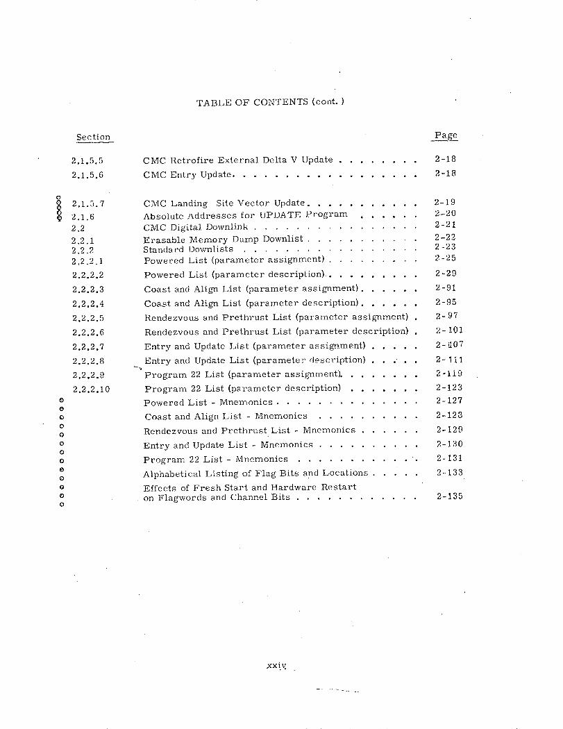
TABLE OF CONTENTS (cont.)
CMC Retrofire External Delta V Update ........
CMC Entry Update. .................
CMC Landing Site Vector Update. ..........
Absolute Addresses for UPDATE Program .....CMC Digital Downlink ................
Erasable Memory Dump Downlist . .......Standard Downlists .................Powered List (parameter assignment) .........
Powered List (parameter description) .........
Coast and Align List (parameter assignment). .....
Coast and Align List (parameter description). .....
Rendezvous and Prethrust List (parameter assignment)
Rendezvous and Prethrust List (parameter description)
Entry and Update List (parameter assignment) .....
Entry and Update List (parameter description) . .. .
Program 22 List (parameter assignment). .......
Program 22 List (parameter description) .......
Powered List - Mnemonics ..............
Coast and Align List - Mnemonics ..........
Rendezvous and Prethrust List - Mnemonics ......
Entry and Update List - Mnemonics ..........
Program 22 List - Mnemonics ........... .
Alphabetical Listing of Flag Bits and Locations .....
Effects of Fresh Start and Hardware Restarton Flagwords and Channel Bits ............
xxiv
Section
2.1.5.5
2.1.5.6
Page
2-18
2-18
2.1.5.7
2.1.62.22.2.12.2.22.2.2.1
2.2.2.2
2.2.2.3
2.2.2.4
2.2.2.5
2.2.2.6
2.2.2.7
2.2.2.8
2.2.2.9
2.2.2.100000000000000o
2-192-202-212-222 -232 -25
2 -29
2 -91
2-95
2-97
2- 101
2- 107
2-111
2-119
2-123
2-127
2-128
2-129
2-130
2-131
2--133
2-135

SECTION 2
DATA LINKS
2. 0 Introduction
This volume, Section 2 of the Guidance System Operations Plan for
Manned CM Earth Orbital and Lunar Missions using Program COLOSSUS
describes the GNCS Data Links: Digital Uplink to CMC (P27) and CM
Digital Downlink for use on these missions.
The material of Section 2 of this GSOP is arranged:
2. 1 Digital Uplink to CMC (P27)
2.2 CMC Digital Downlink
2-1

2. 1 Digital Uplink to CMC (P27)
By means of the CMC UPLINK, ground control can inse'-t data or issue instruc-
tions to the CMC in the same manner that these functions are normally performed
by the spacecraft crew in using the DSKY keyboard.. The CMC is programmed to
accept the following UPLINK inputs:
1. LIFTOFF TIME INCREMENT: Provides ground capability to increment
or decrement the CMC clock, LM and CSM state vector times and TEPHEMatime)
with a double precision octal time value, scaled centiseconds/22 8
2. CONTIGUOUS BLOCK UPDATE: Provides ground capability to update
from 1 to 18 consecutive E memory registers in the same EBANK.
3. SCATTER UPDATE: Provides ground capability to update from 1 to 9 non-
consecutive E memory registers in the same or different EBANKs.
4. OCTAL CLOCK INCREMENT: Provides ground capability to increment or
decrement the CMC clock with a double precision octal time value scaled
centiseconds /228.
All information received by the CMC from the uplink is in the form of keyboard
characters. Each character is assigned an identifying code number called its
character code. Each character code transmitted to the CMC is sent as a triply
redundant uplinlk word preceded by a leading "1" bit. Thus, if C is the 5-bit
character code, then the 16 bit uplink word has the form:
1CCC
where C denotes the bit-by-bit complement of C. (Table 2-1 defines all the legal
input keycodes. ) To these 16 bits of information the ground adds a 3-bit code
specifying the system aboard the spacecraft which is to be the final recipient of the
data and a 3-bit code indicating the spacecraft which should receive the information.
The 22 total bits are sub-bit encoded (replacing each bit with a 5-bit code for trans-
mission). If the message is received and successfully decoded, the on-board receiver
will send back an 8-bit "message accepted pulse" to the ground and shift the original
16 bits of the uplinkword to the CMC (1 C C C). The leading "1" bit causes an inter-
rupt within the CMC after all 16 bits have been shifted from the uplink receiver.
During ground testing the count of UPRUPTS and the sum of the CCC codes entering
the AGC are accumulated in erasable registers, permitting a count and sum-check on
data transmitted UPLINK to the AGC. This feature will not be used in flight because
the summing of uplink data is disabled.
Any ground command sequence normally transmitted via the uplink may b,
duplicated by the astronaut via the keyboard. All reference to uplink words used in
2-2

TABLE 2-1
Character
0
1
2
3
4
5
6
7
8
9
VERB
*NOUN
ENTER
ERROR RESET
CLEAR
KEY RELEASE
+
Uplink Word
1 10000 01111 10000
1 00001 11110 00001
1 00010 11101 00010
1 00011 11100 00011
1 00100 11011 00100
1 00101 11010 00101
1 00110 11001 00110
1 00111 11000 00111
1 01000 10111 01000
1 01001 10110 01001
1 10001 01110 10001
1 11111 00000 11111
111100 00011 11100
1 10010 01101 10010
1 11110 00001 11110
1 11001 00110 11001
1 11010 00101 11010
1 11011 00100 11011
NOTE: It is good operational procedure to end every uplink messagewith a KEY RELEASE.

this section are in the form transmitted from the uplink receiver to the CMC. There-
fore, they do not contain the vehicle or subsystem addresses added by the ground
facilities.
During update program (P27) execution, the following registers may be moni-
tored via the P27 Downlink List:
1. UPBUFF - Contains all input data, including index value, ECADR value(s)
and update parameters. There are 20 (decimal) UPBUFF registers numbered
sequentially from UPBUFF + 0 to UPBUFF + 19D where the D indicates decimal
notation.
2. UPVERB - Contains second digit of update verb being used, e. g., "0" for
Verb 70, "1" for Verb 71, etc.
3. UPOLDMOD - Contains value of program interrupted by P27, e.g., 00, 02,
or 20 for programs 00, 02, or 20; program 27 is inhibited from interrupting
any other programs.
4. COMPNUMB - Contains octal value of number of components to be processed
by P27. Once set, it remains fixed during complete update operation.
5. UPCOUNT - Used for indexing UPBUFF. The contents of this register may
vary from one (1) to the value contained in COMPNUMB. This register always
contains the octal identifier of the parameter that is being loaded.
If the CMC received an improperly coded word from the uplink receiver during the
load (i.e., not "1 CMJC") it sets BIT 4 of FLAGWRD7 to "one", which is transmitted
via Downlink to the ground station. When this occurs, the ground station should
correct the transmission by sending the following uplink word:
1 00000 00000 00000
(which clears the INLINK register) and follow this by transmitting "ERROR RESET"
(which will set BIT 4 of FLAGWRD7 to zero).:** If "CLEAR" is transmitted immediately
following "ERROR RESET", the ground station then may begin the corrected trans-
mission with the first word of the 5 octal digits that was being sent when the alarm
condition occurred. The "CLEAR" button is used after the "ERROR RESET" to
blank the data display register (R1). The ground station should then continue the
update by using UPCOUNT to indicate the specific parameter being processed and
resume the update function by re-transmitting the parameter beginning with the first
octal character.
It is possible to update when program lights are blanked by a FRESH START
(MODREG is 777778).
<* "ERROR RESET" must be sent via uplink to set BIT4 of FLAGWRD7 to zero.DSKY "ERROR RESET" has no effect.
2-4
GSOP # R-577 PCR# 1051 Rev. 15

If the ground wishes to continue loading without transmitting the "CLEAR" code it
must determine which character was in error when failure occurred, and resume
uplink transmission from the point of failure. This may be determined by monitor-
ing the display in R1 as well as the contents of UPCOUNT.
This program may be entered only from P00, P02, or P20 Option 1, 2,
or 5 for the CM. If the CMC is not in one of the programs indicated above when any
update VERB is sent uplink, the "Operator Error" lamp will be illuminated, the
uplink activity light will be turned "OFF" and the computer will ignore the request,
via the specified update VERB, to transfer control to P27.
2.1.1 CM LIFTOFF TIME INCREMENT
To initiate a double precision LIFTOFF octal time increment the
ground station transmits "VERB70ENTER".
2.1.1.1 Program 27 Verification
The ground station should then await confirmation via Downlink that
the CMC is in Program 27.
If P27 is entered, the CMC puts the old program number in UPOLDMOD,
sets UPCOUNT to "one", selects the P27 Downlink List for Downlink trans-
mission and flashes V21N01 which requests a data load for UPBUFF + 0.
If P27 is entered for a Verb 70 update, 0 is placed in UPVERB and 2
is placed in COMPNUMB. Following P27 verification and confirmation of
UPVERB and COMPNUMB sent via Downlink, the ground station should trans-
mit the double precision octal time XXXXX ENTER XXXXX ENTER, where
time is in centiseconds sealed 22 8 A negative time value (decrement)
should be transmitted in one's complement form. It should be noted that
UPCOUNT is incremented by 1 after the ENTER following the most signifi-
cant part of the double precision time. P27 uses the contents of UPCOUNT
to calculate the next IUPBUFF location for the V21N01.
2.1.1.2 Data Verification and Termination
After the final ENTER associated with the last update has been trans-
mitted, P27 flashes V21N02 which is a request to the ground station to verify
all the update data and to perform one of the following functions:
1. Accept all the update data entered
2. Modify some or all of the update data
3. Reject all of the update data
2-5

2.1.1.2.1 Accept All the Update Data Entered
If the ground station verifies that the content of the UPBUFF register
is correct, it should transmit "VERB33ENTER" to signal P27 to process the
update data. For the Verb 70 update, P27 inverts BIT 3 of FLAGWRD7 and
determines if the State Vector data is being used by the orbital integration
routine. If so, further P27 instruction executions are delayed (P27 dormant)
until the integration routine is complete. A display of "27" in the program
lights, along with a ground verification that BIT3 of FLAGWRD7 has been
inverted and that the operator error light is "OFF", should indicate to the
operator that the completion of P27 is temporarily being delayed.
After P27 is re-activated or if it initially finds that the integration
routine is not in use, it will inhibit other routines from using State Vector
data and complete the data verification requirements for the specific update
Verb in use. (For each Verb, see appropriate verification section.)
2.1.1.2.1.1 Verb 70 Double Precision Time Verification
Program 27 verifies that the double precision octal time can be sub-
tracted from the CMC clock without causing overflow. (For this operation
two of the UPBUFF registers, UPBUFF + i8D and 19D, are used as tempor-
ary buffers for TIME2 and TIME1. ) If the double precision input timne can
be subtracted from the CMC clock without causing overflow, P27 proceeds to
increment TEPHEM and decrement the CMC clock, the CSM State Vector
time, and the LM State Vector time. Program 27 will then turn the uplink
activity light "OFF", replace the downlink list code in DNLSTCOD with the
code for the previous program, release the State Vector data for other routines,
and reinstate the previous program.
If, on the other hand, an overflow would occur, P27 will leave the CMC
clock intact and turn the operator error light "ON". It will then turn the
uplink activity light "OFF", replace the downlink list code in DNLSTCOD
with the code for the previous program, release the State Vector data, and
reinstate the previous program.
2.1.1.2.2 Modify Some or All of the Update Data
If during the verification time some of the UPBUFF registers are
found to be in error, the ground station may make corrections by either of
the following methods:
a. Individual parameters in UPBUFF + 0 to UPBUFF + 19D may be
2-6

changed by sending a two digit octal identifier followed by the ENTER
code. For example, if input word 2 (UPBUFF+1) required change, the
ground station would transmit "02ENTER". This causes P27 to display
the UPBUFF+1 address in R3 and flash V21N01, requesting a new octal
data load from the ground. After transmission of the data and its ENTER
code, P27 repeats the V21N02 flash to request data acceptance, modifi-
cation or rejection (section 2. 1. 1. 2). NOTE: If the octal identifier
is < 0 or > COMPNUMB, P27 will continue the V21N02 flash and
completely disregard the value just entered. It should also be noted
that the contents of UPCOUNT is never changed during line by line
correction.
b. If several parameters are to be modified, the ground station may
change each separately as in step "a" above, or it may choose to
terminate and re-initiate the load. To terminate the load the ground
must transmit "VERB34ENTER" which will cause the CMC to return to
the program it was in before the update was initiated. (P27 turns the
uplink activity light "OFF", and switches to the previous Downlink
list before returning control to the other program.) To resume its
update the ground station would re-transmnit the update VERB followed
by the complete update load.
2. 1. 1. 2. 3. Reject All the Update Data
Update data may be rejected at any time by terminating a load. This is
accomplished with the VERB34ENTER sequence described in part "b" of
section 2. 1.1. 2. 2.
2.1. 1. 2. 4 Effects and Use of "VERB33ENTER"
1. During data loads and prior to the V21N02 flash, transmission of
VERB33ENTER will be ignored by P27.
2. During V21N02 flashing, transmission of VERB33ENTER will
initiate the procedure described in section 2. 1. 1. 2. 1.
3. If line by line correction is initiated (section 2. 1. 1. 2. 2), trans-
mission of VERB33ENTER after the octal identifier has been entered
will be ignored by P27.
2-7

2.1.2 CM Contiguous Block Update
To initiate a contiguous E-memory update the ground station should
transmit "VERB71ENTER".
Before sending the update data the ground station should perform
Program 27 verification as defined in the first three paragraphs of section
2.1.1.1. If P27 is entered, 1 is placed in UPVERB and in UPCOUNT.
The verb 71 data format is defined in section 2.1.2.i below and the data
load requirements are described in section 2.1.2.2.
2.1.2.1 VERB71 Data Entry Format
The VERB71 update data format is as follows (all Es represent ENTERs):
I I E
AAAA E
XXXXXE
XXXXXE
XXXXXE
where:
1. 3< II< 24 octal. This is the index value used by P27 to process
the update data. The index value represents the total number of numerico
quantities to be loaded, including the index value itself, the starting
address (ECADR) and the update parameters(s). The minimum value of
3 is for a single update parameter load. A maximum value of 24 octal
is allowed since the UPBUFF capacity is a 20 (decimal) register buffer
for P27. This value represents a maximum of 18 update parameters
in addition to the index count and the starting E memory address.
2. AAAA is the first E memory address (ECADR) of the update block to
be processed. Bits 1-8 indicate the relative address (0-3778) within the
selected EBANK and bits 9-11 identify the desired EBANK (0-7). Also,for one data load operation, all update parameters must ultimately be
stored in the same EBANK. Therefore, the starting address and the
length of the block must be chosen so that the complete load
is contained in the same EBANK; i.e., (bits 8 - 1 of AAAA) +11-3
must be < 377 octal.
2-8

3. X X X X X is octal data which is to be loaded. Tn1, data is stored
in sequential order in UPBUFF+2 and following, up to UPBUFF+19D.
Scaling of the data must be the same as that of the internal CMC registers.
2. 1. 2. 2 Data Load Requirements by Ground Station
Following Program 27 verification (V21NOI flashes with the UPBUFF+O
address displayed in R3) the ground station should enter the update data in the
manner described below.
2. 1. 2.2.1 Index Value
The index value I I should be entered as an octal number and visually
verified (displayed in RI) prior to transmitting the ENTER code. This value
should be within the specified limits (see part I section 2. 1.2. 1 for format).
If an index value < 3 or > 24 octal is erroneously keyed-in followed by
the ENTER code, P27 will reject the value and will continue to flash V21N01
until the ground station enters an inde x va lue within the specified limits. (Entry
of a legal value is indicated when the IPIJBUFF41 address value is displayed in
R3 and UPCOUNT contains a 2).
If a legal index value is keyed-in but is found to be in error (displayed
in R1) before the ENTER code is transmitted, the operator may correct his
error by depressing the "CLEAR" key and re-transmitting the new index value
followe'J by the ENTER code. A legally entered value is stored in UPBUF F+O
and COMPNUMB. UPCOUNT is incremented by 1, the next UPBUFF location
is computed and V21N01 continues to flash indicating a request for an ECADR
load.
If, however, the ground station operator loads a legal index value followed
by the ENTER code and then discovers the numeric value to be incorrect
(UPBUFF+O display), then the only means of recovery is to terminate the load
(VERB34ENTER) and re-initiate the update VERB. This procedure is necessary
since invalid index values cannot be changed if entered in COMPNUMB and
will therefore result in an incorrect update if it is not immediately modified.
2.1. 2. 2.2 E Memory Address Value
The second octal data word to be entered must be the first E memory
address (ECADR) of the update data block.
The ENTER code following the ECADR causes P27 to store this value
in UPBUFF+1, increment UPCOUNT by 1, compute the next UPBUFF location
and continue the V21NO1 flash which requests an update data load.

2.1. 2. 2. 3 Update IData
The update parameters which will be stored in sequential E memory
locations beginning with a legitimate E memory address (ECADR), as defined
in part 2 of section 2.1. 2.1, may be loaded in two separate ways.
1. Each octal value may be individually entered and visually verified
(address of data is displayed in R3 and data is displayed in R1) prior to
transmitting the ENTER code.
If data is in error the operator may depress the "CLEAR" key and
retransmit the correct octal value followed by the ENTER code. This
code causes P27 to store the data in.the UPBUFF address specified in
R3. If more data follows, UPCOUNT is incremented by 1, the next
UPBUFF location is'computed and V21N01 continues to flash,
This method of input allows the ground station to make immediate
corrections if data errors are detected and to visually verify that each
data word is loaded into its specified E memory location.
2. The second Method of input is to transmit all the octal update data
as quickly as possible and then perform a visual verification of all the
data in the UPBUFF registers as specified in section 2. 1. 1. 2.
2.1. 2. 3 VERB71 Contiguous Block Update Verification
The last ENTER of the update sequence causes P27 to flash V21N02.
This is a request to the ground station to accept, modify or completely reject
the data load as specified in 2.1.1,2 sections.
VERB33ENTER also causes P27 to check the validity of the ECADR value
stored in UPBUFF+1 (this value must meet the requirements specified in part 2
of section 2. 1. 2. 1). If the ECADR value is illegal, P27 rejects all input data,
replaces Program 27 with the previous program value, turns the uplink activity
light "OFF", turns the operator error light "ON" and switches to the Downlinklist
for the previous program.
A valid ECADR causes P27 to transfer all the update data from the.
UPBUFF registers into the specified E memory registers, replace program 27
with the previous program value, turn the uplink activity light "OFF", switch to
the Downlink list for the previous program and release the State Vector data.
2.1.3 CM Scatter Update
To initiate an E memory update in non-contiguous E memory locktions
the ground station should transmit "VERB72ENTER".
Before sending the update data the ground station should perform
Program 27 verification as defined in the first two paragraphs of section 2.1.1. 1,

If P27 is entered for a VERB72 update, a 2 is placed in UPVERBand a
1 in UPCOUNT. Following P27 verification the ground station performs this
update exactly as described for the VERB71 updates. The differences in these
two update verbs are noted in the following section.
2. 1. 3. 1 VERB72 Data Entry Format
The VERB72 update format is defined as follows:
I I E
AAAAE
XXXXXE
AAAAE
XXXXXE
AAAAE
X N X X X EI
where:
1. 3 I I I •24 octal. The difference between this index value and the
VERB71 index value is that this value must always be odd. This is due
to the fact that each update parameter must have its specified E memory
address. Thus, the index count includes itself and up to 9 pairs of up-
date words. An even number index value, although accepted at this point
in the procedure, will cause rejection of VERB72 data as indicated in
section 2. 1.3.3. Additionally, Program 27 is replaced with the previous
program value, the uplink activity light is turned "OFF", the operator
error light is turned "ON", the State Vector data is released and the
Downlink list is switched for use by the previous program.
2. All A A A As represent the ECADRs. (Each :\ A A\ is the ECA.DR
of the register to he loaded with the X X X X X immediately followin. )
Note that update data entered via \TVERI372 may he loaded into different
I': AN K s.
3. All X X X X Xs are in octal and scaled the same as the internal
CMC registers.
2. 1. 3. 2 Data Load Requirements by Ground Station
The load requirements of VERB72 are identical to VERB71 (see sections
2. 1.2.2 and 2. 1. 2. 2.1 through 2. 1. 2.2. 3).
2-11

2.1.3. 3 VERB72 Scatter Update Verification
The last ENTER of the update sequence will cause P27 to flash
V21N02. This is a request to the ground to accept, modify or completely
reject the data load as specified in 2.1.1.2 sections.
VERB33ENTER causes P27 to verify that COMPNUMB is odd. If
COMPNUMB is even, P27 will not transfer the data into the specified E
memory registers; instead it will turn on the Operator Error Light, turnoff
Uplink Activity Light, transfer to previous program and downlist.
If, however, COMPNUMB is valid P27 will perform
exactly as specified in the third paragraph of section 2.1.2. 3.
2.1.4 CMC Octal Clock Increment
To initiate a double precision octal time increment the ground station
transmits "VERB73ENTER".
The loading procedure for this update is identical to the VERB70
update defined in section 2.1.1 except that 3 is placed in UPVERB instead of 0.
If the update is acceptable, it is immediately used to increment the
clock (i. e., positive double precision time is added to the clock). No delay
is encountered if the orbital integration routine is in use since the CSM and
LM state vector time registers and the TEPHEM register are' not modified.
2-12
PCR # 1051 Rev. 15GSOP # R-577

2. 1. 5 Use of the Contiguous Block Update VERB
VERB 71, defined in section 2. 1. 2, can be used to perform the follow
ing updates:
1. CMC CSM/LM STATE VECTOR UPDATE2. CMC DESIRED REFSMMAT UPDATE3. CMC REFSMMAT UPDATE4. CMC EXTERNAL DELTA V UPDATE5. CMC RETROFIRE EXTERNAL DELTA V UPDATE6. CMC ENTRY UPDATE7. CMC LANDING SITE VECTOR UPDATE
In defining each of these updates, it is assumed that the ground station has
transmitted VERB71 ENTER and performed Program 27 verification as re-
quired prior to transmittal of the index value, ECADR and update parameters.
It is also assumed that final verification of each update will be done as speci-
fied in section 2. 1. 2. 3.
2.1.5.1 CMC CSM/LM STATE VECTOR UPDATE
This data consists of a single precision state vector identifier, three (3)
double precision components of position, three (3) double precision components
of velocity and a double precision time. The identifier (UPSVFLAG) indicates
CSM or LM and whether coordinates are earth-centered or moon-centered as
follow s:
1 = CSM 2 = CSM-1 = LM earth-centered * -2=LM moon-centered
Note that the CMC, at the next permanent memory state-integration, may
change the origin, based upon computed position. The position and velocity
components should be in reference coordinates scaled as follows:
earth-centered moon-centered
Position meters/22 9 meters/22 7
Velocity (meters/centisecond)/27 (meters/centisecond)/25
The time associated with the state vector should be relative to CMC clock zero.
The identifier is scaled units/21 4 . Time is scaled centiseconds/22 8 .
The CMC is a fixed point machine with the point just to the left of the
most significant bit.
The scaling indicated above will be sufficient to force the 3 components
of position and the 3 components of velocity and time to numbers less than one.
To form the double precision quantities ready for coding and trans-
mission, the scaled magnitudes of time and each component of position and velo-
city should be expressed as two binary words as follows:
*If a quantity other than 0, -0, 2 or -2 is loaded into UPSVFLAG, the datawill also be interpreted as earth-centered. A 0 or -0 will update the UPSVFLAGerasable but the CMC will not perform a state vector update. In the othernumeric cases a valid state vector update will be performed (earth-center).
2-13

1st word:
0 X X X X X X X X X X X X X X
1 22 2-3 2-4 2-5 -6 2-7 28 2-9 2-10 2-11 2-12 2-13 -14
2nd word:
0 X X X X X X 'X X X X IX X X X
2 - 15 2 - 16 -17 2 - 18 2 - 19 2 - 20 2 - 2 1 - 2 2 - 2 3 - 2 4 2-26 2-27 2-28
Each X above represents a binary bit of the appropriate magnitude,
the place value of which is indicated below the corresponding X. Once the
magnitude of the component is accounted for in the above 28 X's, the sign
must be considered.
If the component is positive, the words remain as formed; if the com-
ponent is negative, the "Is complement" of the 2 words is used (all l's are
replaced by 0's and all 0's by l's.)
The first word is then transformed into a 5 character octal word. The
first character is the octal equivalent of the first three bits, the second char-
acter is the octal equivalent of the next three bits, etc. This word is referred
to as the "most significant part" of data in the text below. Similarly, the
second word is transformed into a 5 character octal word which is the 'least
significant part" of the data. Table 2-1 lists all the uplink characters with their
corresponding binary format.
The CMC CSM/LM STATE VECTOR UPDATE data must be sent in the
following sequence:
Octal DataIdentifier Value Data Definition
1 218 (index value) ENTER
2 (AAAA) (ECADR - UPSVFLAG) ENTER
3 XXXXX (identifier) ENTER
4 XXXXX (most sig. part of X position) ENTER
5 XXXXX (least sig. part of X position) ENTER
6 XXXXX (most sig. part of Y position) ENTER
7 XXXXX (least sig. part of Y position) ENTER
108 XXXXX (most sig. part of Z position) ENTER
118 XXXXX (least sig. part of Z position) ENTER
Refer to Paragraph 2. 1.6 to obtain the absolute address (ECADR) forthis UPDATE.
2-14
2

OctalIdentifier
128
138
148
158
168
178
208
218
where each
DataValue
XXXXX
XXXXX
xxxxx
XXXXX
XXXXX
XXXXX
XXXXX
XXXXX
"A", " X"
Data Definition
(most sig. part of X velocity) ENTER
(least sig. part of X velocity) ENTER
(most sig. part of Y velocity) ENTER
(least sig. part of Y velocity) ENTER
(most sig. part of Z velocity) ENTER
(least sig. part of Z velocity) ENTER
(most sig. part of time from CMC clock zero) ENTER
(least sig. part of time from CMC clock zero) ENTER
and "ENTER" above represent an uplink word.
2.1.5.2 CMC DESIRED REFSMMAT UPDATE
XSMD - XSMD + 17 is a 3 x 3 double precision matrix which represents the
Reference to Stable Member Desired Transformation.
The elements of the matrix are scaled, units/21.
The following relations must hold:
1. The inner product of any row with itself must equal 0. 25
2. The inner product of any column with itself must equal 0. 25
3. -The inner product of any row with another row must equal 0
4. The inner product of any column with another column must equal 0
The CMC DESIRED REFSMMAT UPDATE must be sent in the following sequence:
DataValue
248
(AAAA) *
XXXXX
XXXXX
XXXXX
XXXXX
XXXXX
XXXXX
XXXXX
Data Definition
(index value) ENTER
(ECADR-XSMD) ENTER
(most sig. part of Row l-Col. 1)
(least sig. part of Row 1 Col. 1)
(most sig. part of Row 1 Col. 2)
(least sig. part of Row 1 Col. 2)
(most sig. part of Row 1 Col. 3)
(least sig. part of Row 1 Col. 3)
(most sig. part of Row 2 Col. 1)
ENTER
ENTER
ENTER
ENTER
ENTER
ENTER
ENTER
Refer to Paragraph 2. 1. 6 to obtain the absolute address (ECADR) for this UPDATE.
2-15
OctalIdentifier
1
2
3
4
5
6
7
108
118
Octal DataIdentifier Value Data Definition
.(least sig. part
(most
(least
(nmost
(least
(most
(least
(most
(least
(most
(least
sig.
sig.
sig.
sig.
sig.
sig.
sig.
sig.
isg.
sig.
part
part
part
part
part
part
part
part
part
part
of Row 2 Col.
of Row 2
of Row 2
of Row 2
of Row 3
of Row 3
of Row 3
of Row 3
of Row 3
of Row 3
of Row 3
Col. 2)
Col. 2)
Col. 3)
Col. 3)
Col. 1)
Col. 1)
Col. 2)
Col. 2)
Col. 3)
Col. 3)
1) ENTER
ENTER
ENTER
ENTER
ENTER
ENTER
ENTER
ENTER
ENTER
ENTER
ENTER
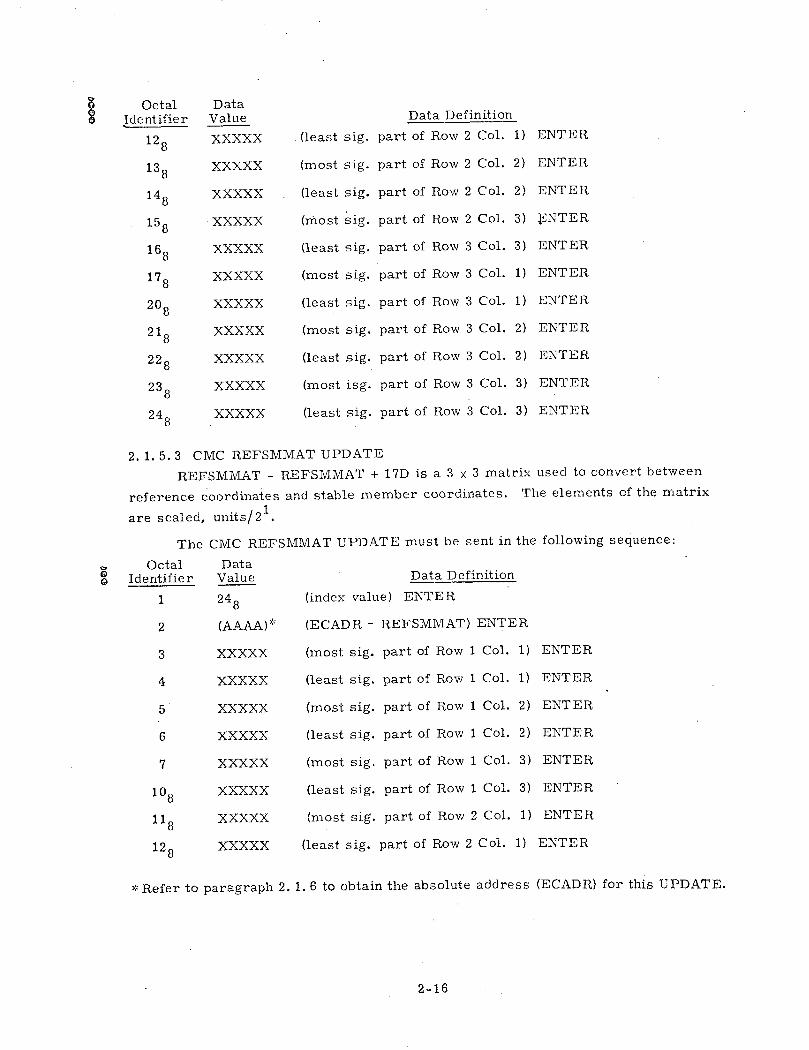
2. 1. 5.3 CMC REFSMMAT UPDATE
REFSMMAT - REFSMMAT + 17D is a 3 x 3 matrix used to convert between
reference coordinates and stable member coordinates. The elements of the matrix
are scaled, units/21.
The CMC REFSMMAT UPDATE must be sent in the following sequence:
DataValue
248
(AAAA)
XXXXX
XXXXX
XXXXX
XXXXX
XXXXX
XXXXX
XXXXX
XXXXX
Data Definition
(index value) ENTER
(ECADR- REFSMMAT) ENTER
(most sig. part of Row 1 Col. 1)
(least sig. part of Row 1 Col. 1)
(most sig. part of Row 1 Col. 2)
(least sig. part of Row 1 Col. 2)
(most sig. part of Row 1 Col. 3)
(least sig. part of Row 1 Col. 3)
(most sig. part of Row 2 Col. 1)
(least sig. part of Row 2 Col. 1)
ENTER
ENTER
ENTER
ENTER
ENTER
ENTER
ENTER
ENTER
* Refer to paragraph 2. 1. 6 to obtain the absolute address (ECADR) for this UPDATE.
2-16
128
138
148
158
168
178
208
218
228
238
248
XXXXX
XXXXX
XXXXX
XXXXX
XXXXX
XXXXX
XXXXX
XXXXX
XXXXX
XXXXX
XXXXX
0o
OctalIdentifier
1
2
3
4
5
6
7
108
118
128
Data Definition
(most sig. part of Row 2 Col. 2) ENTER
part of Row 2
part of Row 2
part of Row 2
part of Row 3
part of Row 3
part of Row 3
part of Row 3
part of Row 3
part of Row 3
Col.
Col.
Col.
Col.
Col.
Col.
Col.
Col.
Col.
2) ENTER
3) ENTER
3) ENTER
1) ENTER
1) ENTER
2) ENTER
2) ENTER
3) ENTER
3) ENTER
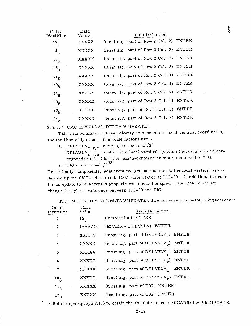
2. 1.5.4 CMC EXTERNAL DELTA V UPDATE
This data consists of three velocity components in local vertical coordinates,
and the time of ignition. The scale factors are
1. DELVSLV (meters/centisecond)/27X, y, z
DELVSLV z must be in a local vertical system at an origin which cor-x, y, zresponds to the CM state (earth-centered or moon-centered) at TIG.
2. TIG centisecond5/22 8
The velocity components, sent from the ground must be in the local vertical system
defined by the CMC-determined, CSM state vector at TIG-30. In addition, in order
for an update to be accepted properly when near the sphere, the CMC must not
change the sphere reference between TIG-30 and TIG.
The CMC EXTERNAL DELTA V UPDATE data must be sent inthe following sequence:
Octal DataIdentifier Value Data Definition
1 i28 (index value) ENTER
(AAAA)*' (ECADR- DELVSLV) ENTER
XXXXX
XXXXX
XXXXX
XXXXX
XXXXX
XXXXX
XXXXX
XXXXX
(most sig.
(least sig.
(most sig.
(least sig.
(most sig.
(least sig.
(most sig.
(least sig.
part of DELVSLVx) ENTER
part of DELVSLV x) ENTER
part of DELVSLV yxENTER
part of DELVSLV y) ENTERpart of DELVSLVz) ENTER
part of DELVSLV z ) ENTER
part of DELVSLVz) ENTER
part of TIG) ENTER
part of TIG) ENTER
* Refer to paragraph 2.1.6 to obtain the absolute address (ECAI)R) for this UPDATE.
2-17
OctalIdentifier
138
148
158
168
178
208
218
228
238
248
DataValue
XXXXX
XXXXX
XXXXX
XXXXX
XXXXX
XXXXX
XXXXX
XXXXX
XXXXX
XXXXX
(least sig.
(most sig.
(least sig.
(most sig.
(least sig.
(most sig.
(least sig.
(most sig.
(least sig.
2
3
4
5
6
7
108
118
128
P

2.1.5.5 CMC RETROFIRE EXTERNAL DELTA V UPDATE
This data consists of the latitude and longitude of the entry target,
three velocity components in local vertical coordinates and the time of
ignition. The scale factors are:
1. GEODETIC LAT(SPL3 degrees/360 (North positive)
2. LNG (SPL) degrees/360 (East positive)
3. DELVSLV (meters/centisecond)/27X, y, z
4. TIG centiseconds/22 8
The CMC RETROFIRE EXTERNAL DELTA V UPDATE date must be
sent in the following sequence:
Octal Data
Identifier Value Data Definition
1 168 (index value) ENTER
2 (AAAA) (ECADR- LAT(SPL)) ENTER
3 XXXXX (most sig. part of LAT (SPL) ) ENTER
4 XXXXX (least sig. part of LAT (SPL) ) ENTER
5 XXXXX (most sig. part of LNG (SPL) ) ENTER
6 XXXXX (least sig. part of LNG (SPL) ENTER
7 XXXXX (most sig. part of DELVSLV x ) ENTER
108 XXXXX (least sig. part of DELVSLVx) ENTER'
118 XXXXX (most sig. part of DELVSLVy) ENTER
128 XXXXX (least sig. part of DELVSLVy) ENTER
138 XXXXX (most sig. part of DELVSLV z ) ENTER
148 XXXXX (least sig. part of DELVSLV z ) ENTER8 z
158 XXXXX (most sig. part of TIG) ENTER
168 XXXXX (least sig. part of TIG) ENTER
2.1. 5. 6 CMC ENTRY UPDATE
This data consists of the latitude and longitude of the entry target.
The scale factors are:
1. GEODETIC LAT(SPL) degrees/360 (North positive)
2. LNG (SPL) degrees/360 (East positive)
The CMC ENTRY UPDATE data must be sent in the following
sequence:
:Refer to paragraph 2. 1.6 to obtain the absolute address (ECADR) forthis UPDATE.
2 -18

DataValue
068
(AAAA) '*
XXXXX
XXXXX
XXXXX
XXXXX
Data Definition
(index value) ENTER
(ECADR-LAT (SPL)) ENTER
(most sig. part of LAT (SPL))
(least sig. part of LAT (SPL))
(most sig. part of LNG (SPL))
(least sig. part of LNG (SPL))
ENTER
ENTER
ENTER
ENTER
2.1. 5.7 CMC Landing Site Vector Update
This data consists of three double-precision position components X, Y, Z,
defining the lunar landing site in moon-fixed coordinates, scaled meters/227.
The CMC LANDING
sequence:
Octal DataIdentifier Value
1 108
2 (AAAA)*
3 XXXXX
4 XXXXX
5 XXXXX
6 XXXXX
7 XXXXX
108 XXXXX
SITE VECTOR UPDATE data must be sent in the following
Data Definition 8o(index value) ENTER
(ECADR-RLS) ENTER
(most sig. part of RLS X-component) ENTER
(least sig. part of RLS X-component) ENTER
(most sig. part of RLS Y-component) ENTER
(least sig. part of RLS Y-component) ENTER
(most sig. part of RLS Z-component) ENTER
(least sig. part of RLS Z-component) ENTER
X* Refer to paragraph 2. 1. 6 to obtain the absolute address (ECADR) for this UPDATE.
2-19
OctalIdentifier
1
2
3
4
5
6

2.1. 6. Absolute Addresses for UPDATE Program
ASSEMBLE REVAIS1I.; 072 (.F AGC PR23Cfi-R AP-TEMI-S BY UASA 242 l-L4--1l
ABSLUTE LOCATIONS FOR UPDATES
ECADI-<
j1501
G C, 3<;, 6
Li1733
C, 34; , i'
- -ECADA
-ECADR
ECADR
-E4AD-F
-.- -- CADR
MNEMONI C
-U'PSV-F-L AG
S'AD
REF SMMAT
DELV. LV
LAT( SPL !
L.2Q25- Fa_- Pr A i I
2-20

2.2 CMC Digital Downlink
The downlink format is controlled by aCMC program. This program is
entered on an interrupt caused by an "endpuise" from the telemetry system. The
program loads the content of the next two 16-bit CMC registers that are to be trans-
mitted into channels 34 and 35. The loading is accomplished according to the format
described ifr the next paragraph.
Each downlist word consists of 33 significant bits plus seven repetition bits.
The first bit is a "word order code bit". The next 16 bits comprise the contents of
one 16-bit CMC register (] 5 bits of data followed by an odd parity bit). The final 16
bits are the content of another 16-bit CMC register. Since the spacecraft downlink
is organized in 8-bit segments, seven "filler bits" are transmitted to follow the 33
bits outlined above in order to use all the downlink space available. These filler
bits are repetitions of the first seven bits of the first CMC register transmitted.
Thus the form in which the content of the two CMC registers is arranged for
transmission as a sequence of 40 CMC downlink bits (represented by X) on channels
34 and 35 may be pictured as shown in the table below:
Channel 34
X X X X X X X X X XXX x X X XReg Word#1 Order 151 141 131 121 111 101 91 81 71 1 1 1 1 1 1
Codeword
Channel 35
Reg 2 X X X X X X X X X X X X X X XReg#2152 142 132 122 112 102 92 82 72 62 52 42 32 22 12 P2
Channel 34
X X X X X X X
Reg 111 151 141 131 121 111 101 repet
Table Showing CMC Downlink Bits
The first word in any list contains the "ID" and synchronization registers and
has a word order code bit of zero. (All other downlink words have word order code
bits of one except word 51 on the standard downlists which has a word order code bit
of zero to indicate the mid-point of the standard downlists'. )The ID register marks the
beginrning of a list and identifies the list being transmitted. The synchronization
(sync) register always contains the same sixteen bits (111 111 011 100 000 0), which
are used to synchronize remote site downlink processing equipment. The cobtent of
the standard lists and the programs in which they are transmitted are described in
section 2. 22.
The standard CMC downlink lists contain 100 downlink words (200 CMC regis-
ters). The CMC digital downlink is transmitted at a rate of 50 words per second at
2 -21

high bit rate and 10 words .at low bit rate. Therefore, transmission of the standard
list requires two seconds at high bit rate and ten seconds at the low bit rate.
2.2.1 Erasable Memory Dump Downlist
Upon reception of a Verb 74 Enter from the keyboard or the uplink,
the computer will interrupt the nominal downlist being transmitted and start
transmitting the erasable memory dump downlist. The first word of the
erasable memory dump downlist is an ID word, 017778 and the same pattern of synch
bits as on the standard list. The word order code for this downlink word will
be zero. The next 129 downlink words have word order codes of one and
make up the remainder f .the 130. word dump downlink list. Word 2 of this
list (i. e. , the word following the ID word) contains a "packed indicator" code
in the first register and the contents of TIME1 in the second-register. TIME1
is the least significant clock register and is described later in this section
under the standard lists. The "packed indicator" identifies which erasable
bank and which pass through that bank is contained in the present list as
follows:
Bits 15 & 14 - zero
Bits 13 & 12 - 00 for 1st pass01 for 2nd pass
Bits 11 thru 9 - gives EBANK number
Bits 8 thru 1 - zeros
The next 128 downlink words (256 registers) are the' contents of the erasable
bank indicated in the packed indicator.
After transmitting the 13( downlink word list (one ID word, one packed
-indicator and time word, and 128 data words), the downlink will transmit the
ID word again, followed by the packed indicator, followed.by the contents of
the next erasable bank etc. In this way, one complete pass through erasable
memory will require 20. 8 seconds for high bit rate, and 104 seconds for low
bit rate. The computer will make two complete passes through the complete
erasable memory before returning to the standard downlist.
2 -22

NOTE: After completion of the erasable dump downlist the current downlist will be
started at the ID word. Since no programs are interrupted during the
transmission of the erasable memory downlist, some of the registers
transmitted may have different contents on different passes through the
erasable.
2. 2. 2 Standard Downlists
For this mission there are five standard downlists, each associated with
a set of programs, as follows:
A. The Powered List is transmitted during
11 Earth Orbit Insertion (EOI) Monitor 0
15 TLI Initiate/Cutoff Program
40 SPS Thrust
41 RCS Thrust
47 Thrust Monitor
61 Entry Preparation Program
B. The Coast and Align List is transmitted during
00 CMC Idling
01 Prelaunch Initialization
02 Gyro Compassing
03 Optical Verification of Gyro Compassing s
06 CMC Power Down
07 CSystem Test
51 IMU Orientation Determination
52 IMU Realign
53 Backup IMU Orientation Determination
54 Backup IMU Realign .
C. The Rendezvous and Prethrust List is transmitted during
20 Universal Tracking .
21 Ground Track Determination
23 Cislunar Midcourse Navigation
29 Time of Longitude Program
30 .External AV Maneuver Guidance_
31 Height Adjust Maneuver (HAM)
32 Co-elliptic Sequence Initiation (CSI)
33 Constant Differential Altitude (CDH)
34 Transfer Phase Initiation (TPI) Guidance
35 Transfer Phase Midcourse (TPM) Guidance
36 Plane Change Maneuver (PC)
37 Return to Earth Maneuver Guidance
72 LM CSI Targeting
73 LM CDH Targeting
74 LM Transfer Phase Initiation (TPI) Targeting
75 LM Transfer Phase Midcourse (TPM) Targeting
2-23

76 Target AV
77 CSM Velocity Vector Update0o 79 Final Rendezvous Program
D. The Entry and Update List is transmitted during
27 CMC Update
62 CM/SM Separation and Pre-entry Maneuver
63 Entry Initialization
64 Post 0. 05 G Entry Mode
65 Up Control Entry Mode
66 Ballistic Entry Mode
67 Final Entry Mode
E. The P-22 List is transmitted during
22 Orbital Navigation24 Rate-Aided Optics Tracking
The list switching is accomplished as follows: Whenever a new program is entered,it sets up a request for its list by placing the appropriate code in the register,DNLSTCOD. The downlink program will transmit the complement of this code asthe ID and use the code to select the appropriate list. The complete list is thentransmitted even if DNLSTCOD is changed during it. This procedure is,of course,not true for the erasable memory dump downlist (see Section 2.2. 1), which completesits required number of passes irrespective of other programs. A computer "restart"(hardware), or 'fresh start" will immediately cause the telemetry list to start withword #1. A "restart" (hardware) will begin the list whose code is in DNLSTCOD buta "fresh start" will always set DNLSTCOD to transmit the Coast and Align list. Anerasable memory dump, if in process, will be interrupted in both cases, and regular
downlist transmission resumed.
Since certain data on the standard downlink lists are only meaningful whenconsidered in multiregister arrays and since the programs which compute these arraysare not synchronized with the downlink program, a "snapshot" is taken of these wordsso that changes in their values will not occur while these arrays are being transmittedto the ground. When a "snapshot" is taken several words are stored at the time thefirst word is transmitted. The other words in the downlist are read at the time oftransmission and therefore the only time homogeneity for them is between the tworegisters making up a single word. The COLOSSUS downlists have the following"snapshots":
Powered List words 2-8, 9-13, 52-58, 59-63Coast and Align List words 2-8, 9-13, 52-58, 59-i63Rendezvous and Prethrust List words 2-8, 9-13, 52-58, 59-63.Entry and Update List words 2-8, 9-13, 52-58, 59-63P-22 List words 2-8, 9-13, 18-24, 25-31,
32-35, 52-54, 59-63
The following is a list of CMC registers making up the various dow:nlists.
A register may contain other quantities during programs in which the CMC nolonger needs to save the primary downlist quantity.
2-24
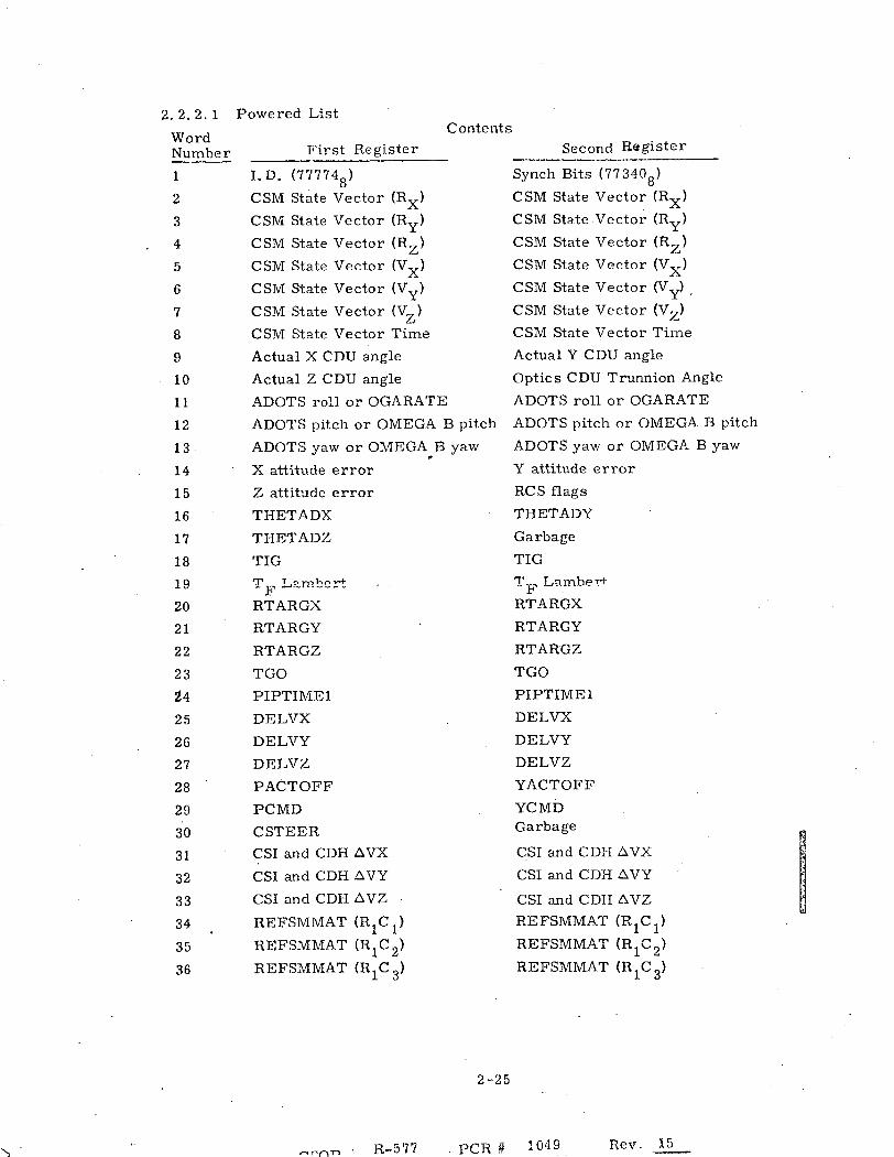
2.2.2.1 P
WordNumber
1
2
3
4
5
6
7
8
9
10
11
12
13
14
15
16
17
18
19
20
21
22
23
24
25
26
27
28
29
30
31
32
33
34
35
36
Powered ListContents
First Register
I. D. (777748)
CSM State Vector (RX )
CSM State Vector (Ry)
CSM State Vector (RZ )
CSM State Vector (VX
)
CSM State Vector (Vy)
CSM State Vector (VZ )
CSM State Vector Time
Actual X CDU angle
Actual Z CDU angle
ADOTS roll or OGARATE
ADOTS pitch or OMEGA B pitch
ADOTS yaw or OMEGA B yaw
X attitude error
Z attitude error
THETADX
THETADZ
TIG
T F L-ambet
RTARGX
RTARGY
RTARGZ
TGO
PIPTIME1
DELVX
DELVY
DELVZ
PACTOFF
PCMD
CSTEER
CSI and CDH AVX
CSI and CDH AVY
CSI and CDH AVZ
REFSMMAT (R 1 C 1 )
REFSMMAT (R 1 C 2 )
REFSMMAT (R 1 C 3 )
Second Register
Synch Bits (773408)
CSM State Vector (RX )
CSM State Vector (Ry)
CSM State Vector (RZ )
CSM State Vector (VX )
CSM State Vector (Vy)
CSM State Vector (VZ )
CSM State Vector Time
Actual Y CDU angle
Optics CDU Trunnion Angle
ADOTS roll or OGARATE
ADOTS pitch or OMEGA B pitch
ADOTS yaw or OMEGA B yaw
Y attitude error
RCS flags
THETADY
Garbage
TIG
TF
Lambert
RTARGX
RTARGY
RTARGZ
TGO
PIPTIME1
DELVX
DELVY
DELVZ
YACTOFF
YCMDGarbage
CSI and CDH AVX
CSI and CDH AVY
CSI and CDH AVZ
REFSMMAT (R1 C 1 )
REFSMMAT (R 1 C 2 )
REFSMMAT (R1C 3 )
2 --25
-,, "r, R-577 . PCR # 1049
I
4
Rev. 15

Contents
WordNumber First Register
37 REFSMMAT (R 2 C 1 )
38 REFSMMAT (R 2 C 2 )
39 REFSMMIAT (R 2 C 3 )
40 Flagword 0
41 Flagword 2
42 Flagword 4
43 Flagword 6
44 Flagword 8
45. DSPTAB+0
46 DSPTAB+2
47 DSPTAB+4
48 DSPTAB+6
49 DSPTAB+8D
50 DSPTAB+10D
51 TIME 2
52 LM State Vector (Rx)
53 LM State Vector (Ry)
54 LM State Vector (Rz)
55 LM State Vector (V4X)
56 LM State Vector (Vy)
57 LM State Vector (VT )
58 LM State Vector Time
59 Actual X CDU angle
60 Actual Z CDU angle
61 ADOTS roll or OGARATE
62 ADOTS pitch or Omega B pitch
63 ADOTS yaw or Omega B yaw
64 X attitude error
65 Z attitude error
66 THETADX
67 THETADZ
68 * RSBBQ
69 Garbage
70 * C31FLWRD
71 * FAILREG+1
72 Optics Shaft
73 PIPAY
Second Register
REFSMMAT (R 2 C 1 )
REFSMMAT (R 2 C2 )
REFSMMAT (R 2 C 3 )
Flagword 1
Flagword 3
Flagword 5
Flagword 7
Flagword 9
DSPTAB+1
DSPTAB+3
DSPTAB+5
DSPTAB+7
DSPTAB+9D
DSPTAB+1 1D
TIME 1
LM State Vector (RX)
LM State Vector (Ry)
LM State Vector (RZ)
LM State Vector (VX)
LM State Vector (Vy)
LM .State Vector (V.TZ
LM State Vector Time
Actual Y CDU angle
Optics CDU trunnion angle
ADOTS roll or OGARATE
ADOTS pitch or Omega B pitch
ADOTS yaw or Omega B yaw
Y attitude error
RCS flags
THETADY
Garbage
RSBBQ+1
Channel 77
FAILREG
FAILREG+2
PIPAX
PIPAZ
* Indicates two single precision quantities that are not indicated otherwise.
2 -26

Contents
First Register
Elevation Angle
Central Angle
Spare
Flagword 10
TEVENT
PCMD
OPTMODES
LM MASS
DAPDATR1
ERROR X
ERROR Z
WBODY (roll) or OMEGAC (roll)
WBODY (pitch) or OMEGAC (pitch)
WBODY (yaw) or OMEGAC (yaw)
REDO COUNTER
Desired FINAL CDUY
IMODES 30
Channel 11
Channel 13
Channel 30
Channel 32
VGTIGX
VGTIGY
VGTIGZ
CDH AVX
CDH AVY
CDH AVZ
Second Register
Elevation Angle
Central Angle
Spare
Flagword 11
TEVENT
YCMD
HOLDFLAG
CM MASS
DAPDATR2
ERROR Y
GarbageWBODY (roll) or OMEGAC (roll)
WBODY (pitch) or OMEGAC (pitch)
WBODY (yaw) or OMEGAC (yaw)
Desired FINAL CDUX
Desired FINAL CDUZ
IMODES 33
Channel 12
Channel 14
Channel 31
Channel 33
VGTIGX
VGTIGY
VGTIGZ
CDH AVX
CDH AVY
CDH AVZ
2 -27
WordNumber
74
75
76
77
78
79
80
81
82
83
84
85
86
87
88
89
90
91
92
93
94
95
96
97
98
99
100
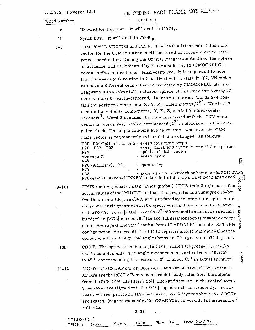
2.2.2.2 Powered List PRECEDING PAGE BLANK NOT FILMED
Word Number Contents
la ID word forthis list. It will contain 777748.
lb Synch bits. It will contain 773408.
2-8 CSM STATE VECTOR and TIME. The CMC's latest calculated state
vector for the CSM in either earth-centered or moon-centered refe-
rence coordinates. During the Orbital Integration Routine, the sphere
of influence will be indicated by Flagword 8, bit 12 (CMOONFLG):
zero= earth-centered; one= lunar-centered. It is important to note
that the Average G routine is initialized with a state in RN, VN which
can have a different origin than is indicated by CMOONFLG. Bit 2 of
Flagword 0 (AMOONFLG) indicates sphere of influence for Average G
state vector: 0 = earth-centered, 1 = lunar-centered. Words 2-4 con-
tain the position components X, Y, Z, scaled meters/229. Words 5-7
contain the velocity components, X, Y, Z, scaled (meters/centi-
second)/27. Word 8 contains the time associated with the CSM state
vector in words 2-7, scaled centiseconds/22 8 , referenced to the com-
puter clock. These parameters are calculated whenever the CSM
state vector is permanently extrapolated or changed, as follows:
P00, P20 Option 1, 2, or 5 - every four time stepsP20, P22, P23 - every mark and every Incorp if CM updatedP27 - update of state vectorAverage G - every cycleV47 -P20 (MINKEY), P24 - upon entryP77P23 - acquisition of landmark or horizon via POINTAXSP20 option 0, 4 (non-MINKEY)-after initial displays have been answered [J
9-10a CDUX (outer gimbal) CDUY (inner gimbal) CDUZ (middle gimbal): The
actual values of the IMU CDU angles. Each register is an unsigned 15-bit
fraction, scaled degrees/360, and is updated by counter interrupts. A mid-
dle gimbal angle greater than 70 degrees will light the Gimbal Locklamp
onthe DSKY. When IMGAI exceeds 750 P20 automatic maneuvers are inhi-
bited; when IMGAI exceeds 85° the ISS stabilization loop is disabled except o
during Average-G when the ';config" bits of DAPDAT R1 indicate SATURN 8
configuration. As a result, the CDUZ register should maintain values that
correspond to middle gimbal angles between -70 degrees and +70 degrees.
10b CDUT. The optics trunnion angle CDU, scaled (degrees-19.7754)/45
(two's complement). The angle measurement varies from -19.775 ° 8to 450, corresponding to a range of 0 ° to about 65 ° in actual trunnion.
11-13 ADOTs (if RCS DAP on) or OGARATE and OMEGABs (if TVC DAP on).
ADOTs are the RCS DAP-measured vehicle body rates (i.e. the outputs
from the RCS DAP rate filter) roll, pitch and yaw, about the control axes.
These axes are aligned withthe RCS jet quads and, consequently, are ro-
tated, with re spect to the NAV base axes, -7.25 degrees about iX. ADOTs
are scaled, (degrees/second)/450. OGARATE, inwordll, is the measured
roll rate.2-29
COLOSSUS 3GSOP # R-577 PCR # 1049 Rev. 15 Date NOV 71
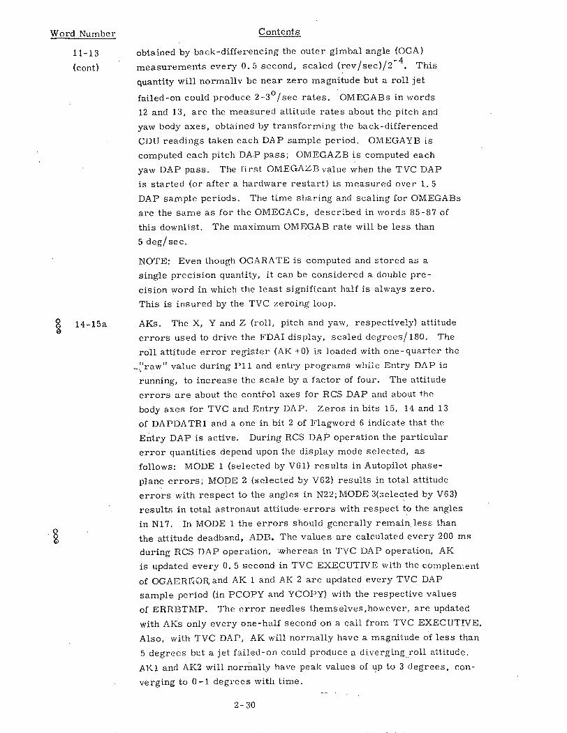
Word Number
11-13
(cont)
Contents
obtained by back-differencing the outer gimbal angle (OGA)
measurements every 0. 5 second, scaled (rev/sec)/2 4. This
quantity will normally be near zero magnitude but a roll jet
failed-on could produce 2-3°/sec rates. OMEGABs in words
12 and 13, are the measured attitude rates about the pitch and
yaw body axes, obtained by transforming the back-differenced
CDU readings taken each DAP sample period. OMEGAYB is
computed each pitch DAP pass; OMEGAZB is computed each
yaw DAP pass. The first OMEGAZB value when the TVC DAP
is started (or after a hardware restart) is measured over 1. 5
DAP sample periods. The time sharing and scaling for OMEGABs
are the same as for the OMEGACs, described in words 85-87 of
this downlist. The maximum OMEGAB rate will be less than
5 deg/sec.
NOTE: Even though OGARATE is computed and stored as a
single precision quantity, it can be considered a double pre-
cision word in which the least significant half is always zero.
This is insured by the TVC zeroing loop.
§ 14-15a AKs. The X, Y and Z (roll, pitch and yaw, respectively) attitude
errors used to drive the FDAI display, scaled degrees/180. The
roll attitude error register (AK +0) is loaded with one-quarter the
"raw" value during P11 and entry programs while Entry DAP is
running, to increase the scale by a factor of four. The attitude
errors are about the contirol axes for RCS DAP and about the
body axes for TVC and Entry DAP. Zeros in bits 15, 14 and 13
of DAPDATR1 and a one in bit 2 of Flagword 6 indicate that the
Entry DAP is active. During RCS DAP operation the particular
error quantities depend upon the display mode selected, as
follows: MODE 1 (selected by V61) results in Autopilot phase-
plane errors; MODE 2 (selected by V62) results in total attitude
errors with respect to the angles in N22; MODE 3(selected by V63)
results in total astronaut attitude errors with respect to the angles
in N17. In MODE 1 the errors should generally remain less than
the attitude deadhand, ADB. The values are calculated every 200 ms
during RCS DAP operation, -whereas in TVC DAP operation, AK
is updated every 0. 5 second in TVC EXECUTIVE with the complement
of OGAERKO©r and AK 1 and AK 2 are updated every TVC DAP
sample period (in PCOPY and YCOPY) with the respective values
of ERRBTMP. The error needles themselves,however, are updated
with AKs only every one-half second on a call from TVC EXECUTIVE.
Also, with TVC DAP, AK will normally have a magnitude of less than
5 degrees but a jet failed-on could produce a diverging roll attitude.
AK1 and A.K2 will normally have peak values of up to 3 degrees, con-
verging to 0-1 degrees with time.
2- 30

Word Number Contents
15b RCSFLAGS. A cell whose individual bits are used in monitoring
the RCS DAP.
Bit Meaning
15 Bit set to 1 during R60 or R67 auto maneuver if high
rate (2 deg/sec) has been specified in R03. Bit is reset
to 0 at termination of auto maneuver.
14 Bit is set to 1 if rate estimates are not good and a repeat of
the rate filter initialization is required. Bit is reset to 0 if the
G&N is in control and the IMU data is usable. Approximately
1 second after bit is reset to 0 the rate filter initialization is
complete.
13 Bit set 1 if the rate damping has not been completed on the
roll axis. Bit is reset to 0 if the rate damping on the roll
axis has been completed.
12 Bit set 1 if the rate damping has not been completed on the
pitch axis. Bit is reset to 0 if the rate damping has been
completed on the pitch axis.
11 Bit set 1 if the rate damping has not been completed on the
yaw axis. Bit reset to 0 if the rate damping has been com-
pleted on the yaw axis.
10.,9 If either or both bits have been set to 1.. there has been a
change in RHC roll command since the last DAP cycle. If
both bits are reset to 0, it implies that no change in the
RHC roll command has occurred since the last DAP cycle.
8, 7 If either or both bits have been set to 1, there has been a
change in RHC yaw command since the last DAP cycle. If
both bits are reset to 0, it implies that no change in the
RHC yaw command has occurred since the'last DAP cycle.
6, 5 If either or both bits have been set to 1, there has been a
change in the RHC pitch command since the last DAP cycle.
If both bits are reset to 0, it implies that no change in the
RHC pitch command has occurred since the last DAP cycle.
4 Bit set 1 indicates that the AK. values should be updated.
Bit is reset to 0 to indicate that the NEEDLE DRIVE routine
should be processed with the AK values which have been
previously acquired.
2-31

Word Number Contents
15b Bit Meaning
(cont) 3, 2 If Bit 3, Bit 2 =112 or 102, it is necessary to follow theinitialization path of the NEEDLE DRIVE routine.
If Bit 3, Bit 2 = 012, it is necessary to follow pass 2 of
the NEEDLE DRIVE routine.
If Bit 3, Bit 2 = 002, it is necessary to follow pass 3 and
greater paths of the NEEDLE DRIVE routine.
1 Bit is set 1 to indicate that the initial pass path in the
T6 program should not be followed. Bit is reset to 0 if
the T6 program should be initialized.
16-17a THETADX, THETADY, THETADZ. During normal RCS DAP
operation, when the CMC Mode switch is in AUTO or HOLD and
there are no RHC commands, these registers contain the desired
current, (i. e., of this DAP cycle opposed to final) roll, pitch, and
yaw CDU angles, treated as 15-bit unsigned fractions and scaled
degrees/360. These quantities are used in the computation of phase
plane attitude errors and are calculated as follows:
1. During automatic maneuvers they are updated every
100 milliseconds.
2. During attitude hold they are constants (the desired CDU
angles to be held).
3. At the end of manual rate maneuvers, after rate damping is
complete, THETADX, Y & Z are set to the current CDU
angles.
4. During manual rate maneuvers and when in FREE mode the
registers are not updated.
17b Garbage.
18 TIG. The time of ignition (prethrust) or time of cutoff (while
thrusting). The changeover in definition for P40 occurs at igni-
tion if an impulsive burn and at first TGOCALC (nominal TIG+2)
if steering. For P15, the changeover occurs at ignition +10
seconds. This item is scaled, centiseconds/228. This parameter is
2 -32

umber
8
nt)
9
Contents
calculated by P31, P32, P33, P34, P35, P36, P72, P73, P74 and
P75. P15, P30, P37, P76 and P77 all require TIG as an input,
although P37 may modify TIG based on correction for burn interval.
In P76/P77, TIG is loaded with targeted ignition time. If the ignition
time must be slipped (alarm 17038), P40 or P41 loads this word
with the new ignition time. After ignition for an impulsive burn,
TIG is loaded with predicted cutoff time, and after the first TGO
calculation (long burn) TIG is loaded with the state vector time
(word 8) plus TGO. After the enter response to the flashing verb 97
(engine fail), the most significant half of TIG is set to -248 and the
least significant half remains unchanged.
DELLT4 (The desired transfer time). The time from TIG until the
target (RTARG) is reached, scaled centiseconds/228. It is used as
an input to the INITVEL subroutine and calculated by each user of
this subroutine.
22 RTARG. The aimpoint vector X, Y, Z, in either earth-centered or
lunar-centered coordinates and scaled meters/22 9 . The origin of
the coordinate system is the same as that of the CSM state vector
at TlC,. Caution must be exercised in ground/AGC communications
whenever the spacecraft is operating near the "sphere-of-influence'!
switchover point. Bit 12, flagword 8 (CMOONFLG) indicates whe-
ther the CSM state vector is earth- or moon-centered. This para-
meter is calculated by P34/P74, P35/P75, and P37.
TGO. The time to go until engine cutoff, scaled centiseconds/22 8
At TIG-5 for an impulsive burn (TGO < 6) it is calculated once to
represent the time from ignition to engine cutoff. If the estimated
maneuver time is greater than six seconds and active steering has
been initiated, TGO becomes the length of the time from the last
PIPA reading to engine cutoff. During a burn in which steering is
used, TGO is calculated every two seconds from the start of steer-
ing until steering is stopped.
PIPTIME1. The time (T2/T1) at which the PIPAs are read, scaled
centiseconds/2 . Integration stores the PREREAD state vector
time in anticipation of reading PIPAs at that time. PIPASR stores
TIME2/TIME1 every two seconds during Average G. Since this
word and words 25-27 are not in a snapshot group, the possibility
exists that this set of data may not be time homogeneous.
2-33
tThis change accomplished in Revision 14 but PCR 325 notation omitted.
?
Word N
1E
(co
10
20-
23
24

§ Word Number
25-27
28
29
° 30a0
O 30b0
Contents
DELVs. The sampled X, Y, & Z PIPA accumulations (velocity
increments) with compensation for PIPA bias and scale factorerrors. These quantities are in the stable member coordinate
system and are scaled, (cm/sec)/(5. 85 x214). Calculation takes
place every two seconds during AVE C. The variation with time
and the range of values depend on the acceleration level and com-
pensation. There is a zeroing of all low-order components and a
momentary zeroing of DELVY and DELVZ prior to the loading of
PIPA contents into respective high-order words (part of READACCS,
or REREADAC task). If no restarts occur the momentary zeroing
would not appear on the downlink. PIPA compensation follows in
Servicer job (inhinted, so that all or no PIPA compensation shows up).
PACTOFF (pitch), YACTOFF (yaw). The SPS engine gimbal-
actuator trim angle estimates in the pitch and yaw planes (used to
align the engine with the vehicle cg), scaled (seconds of arc)/
(85. 41 x 214). These values are added to the DAP filter output
every DAP sample period as part of the engine gimbal servo com-
mand. The variation is usually less than +2 degrees over the course
of a burn. These are equivalent to the upper halves of the double-
precision registers, PDELOFF and YDELOFF. These items are
set initially by astronauts in R03. They change significantly at the
CSM "one-shot" correction time, which is about 3. 4 seconds after
ignition. For the CSM/LM the "one-shot" occurs at TVC initialization
and hence causes no change to PACTOFF or YACTOFF. Incremental
changes are made every 0. 5 second after the "one-shot" correction
and an end-of-burn update is made following the engine shut-down
command.
PCMD (pitch), YCMD (yaw). The pitch and yaw SPS engine gimbal-
actuator position commands from the respective TVC DAPs, scaled
(seconds of arc)/(85. 41 x 214). The expected range of values is
between +1 degree, while the maximum possible values are +6 degrees.
They are calculated at every TVC DAP sample period: 40 ms for
CSM, 80 ms for CSM/LM.
CSTEER. The Cross Product Steering Constant, "c", used by P40/
P41 in the equation Arm = cbAt - Av and certain prethrust compu-
tations. It is scaled "c"/4. The value range will be from -4 to
+4 (less one bit). It is set by P40 prethrust to ECSTEER if a
Lambert burn. It will be zeroed by P40 prethrust if an externalAV burn and also by P41 prethrust.
Garbage
2-34

Word Number Contents
31-33 DELTA VELOCITY (X,Y,Z) at CSI and CDH. In Reference
Coordinates. During P31,P32, P72 contains delta velocity at CSI,
calculated during each iteration of CSI/A subroutine. During P33/ 8P73 contains delta velocity at CDH loaded from words 98-100 of
7 8this list. Scaled (meters/centisecond)/27.
34-39 REFSMMAT. Six elements of REFSMMAT, double precision
quantities, transmitted R 1C1,.R 1
C 2, R 1 C3, R 2 C 1
, R2 C 2, and R2C 3 ,
each scaled 2-
1. REFSMMAT is the 3 x 3 matrix used to convert
between reference coordinates and stable member coordinates.
The remaining three components of REFSMMAT may be computed
as follows:
R 3 C 1 = (R 1 C 2 ) (R 2 C 3 ) - (R 1 C 3 ) (R 2 C 2 )
R 3 C 2 = (R 1 C 3 ) (R 2 C 1 ) - (R 1 C 1 ) (R 2 C 3)
R 3 C 3 = (R 1 C1 ) (R 2 C 2 ) - (R1C 2 ) (R 2 C
1),
where R= ROW and C = COLUMN.
REFSMMAT is calculated in P11, P51, P52. P53 and P54.
40-44 TEN FLAGWORDS (0, 1, ... 9). Bit assignments are as follows:
Flagword Bit Meaning
0 15 Not used. Should always be 0.
0 14 JSWITCH. Bit set to 1 within orbital integration routine
to indicate that extrapolation of W-matrix is being carried
out in orbital integration routine (in contrast to the state
vector extrapolation likewise done by the routine). Would
only become 1 if bit 1 of FLAGWRD3 were 1.
0 13 MIDFLAG. Set to 1 within orbital integration routine at
beginning of time step when magnitude of conic position
vector is greater than the constants rME (earth-centered)
or riMM (moon-centered) and set to 0 if less than these
constants. If MIDFLAG is set to 1 integration will include
secondary body and solar perturbations to the orbit.
2-35

Flagword Bit Meaning
0 12 MOONFLAG. Set by orbital integration to 1 or 0 when
integrating the stored CSM and LM state vectors; 1 indi-
cates lunar orbit, 0 indicates earth orbit. Also set to 1
or 0 in integration when switching coordinate centers.
MOONFLAG is also set to 1 or 0 by callers of INTEGRVS
which specify the state vector to be integrated and in P27,
P76, P77, V66 and V47 when using integration subroutine
to permanently store state vectors.
0 11 NORFHOR. A 1 indicates far horizon. A 0 indicates near
horizon. Set to 0 or I in P23 from astronaut input of near
or far horizon. Used to determine which point of tangency
equation is to be used (near or far).
0 10 ZMEASURE. A 1 indicates measurement planet and pri-
mary planet different. A 0 indicates measurement planet
and primary planet the same. Set 0 in P23 when state
vector sphere of influence and sighting planet measurement
are in the same sphere of influence; otherwise set to 1.
Used in P23 to pick up the vector difference between state
vector and landmark or horizon vector.
0 9 NEEDLFLG. Bit set 1 by a verb 62 or verb 63 and set 0
by a verb 61 (or by a fresh start), used to control the
information presented on the FDAI attitude error needles
by the RCS DAP (it has no effect on the TVC or Entry
DAP's. ) If the bit is 1 and in addition the N220RN17 bit
(bit 6 of flagword 9) is 1, "total attitude error" with respect
to the contents of N22 is displayed, defined as THETAD -
CDU resolved into roll pitch and yaw coordinates. If the
bit is 1 and in addition the N220RN17 bit is 0,. "total astro-
naut attitude error" with respect to the contents of N17, is
displayed, defined as CPHIX - CDU resolved into roll pitch
and yaw coordinates. CPHIX can be loaded with the present
CDU angles by a verb 60. If the bit is 0, then, independent
of other bit settings, RCS DAP phase-plane errors, ERRORX,
ERRORY, and ERRORZ, which are some times called "auto-
pilot following errors" are displayed. Polarity of the error
is,as in the other displays, desired minus actual. The
"total attitude error" and the "total astronaut attitude error"
are defined as a difference between "present" attitude and
2 -36

Flagword Bit Meaning
0 9 an attitude specified in N22 or N17. Consequently, these
(cont) attitude errors may assume large values. The phase plane
attitude errors, however, are quantities used by the RCS
DAP to command jet firings when the CMC MODE SWITCH is
in AUTO and HOLD and thus should generally remain within
the selected RCS DAP attitude deadband.
o 8 IMUSE. Bit is set to 1 to indicate that "IMU IS IN USE. " It
is set to 0 each time a verb 37 program change is processed
(unless UTFLAG or RNDVZFLG = 1) and is set to 1 when R02
is performed for P20, P22, P24, P40, P41, P47, P52, P54,
P61, P62, and R63. It is also set to 1 at the start of P51 and
P53 if the IMU is on. Besides the V37 processing, bit is set
to 0 for P06 and IMU turn off and when P20 terminated via o
V56E or V34 to R22 or R60/R61 display). If the bit is 1 and
the IMU is turned off, alarm 02148 is generated.
0 7 RNDVZFLG. Bit set 1 to indicate that P20 option 0 or 4 (Ren-
dezvous Navigation) has been enabled and is set to 0 for options
1, 2, 5 of P20. P20 may be dormant even if this bit is 1. It
is set to 1 shortly after a proceed on last P20 input display and
reset to 0 by a verb 56, IMU turn off, POODOO and by verb 37 o
input of P00, P22, P23, P24, or P06. It can be set 0 by a
verb 34 response to the V50 N18 display in R60, if R60 was
called fr6m R61. A verb 34 response to a V06N49 display in
R22 will also set the bit to 0.
0 6 R53FLAG. Bit set 1 to indicate that a request for optics marks
(flashing verb 51) has been initiated for R53. R53 is used by
P22, P23, P24, P51, and P52. Bit is reset 0 at the start of
R52 (for use in logic that causes R53 to be initiated if optics
mode not "computer control"). R53 will not be established by
R52 if entered from P20.
0 5 F2RTE. A 1 means Return to Earth Targeting is operating in
the time-critical mode. A 0 means Return to Earth Targeting
is operating in the fuel-critical mode. In the time-
critical mode the program generates a trajectory which
meets the re-entry constraints and returns the space-
craft in the shortest possible time. In the fuel- 6
2-37
GSOP # R-577 PCR # 1051 Rev. 15

Bit Meaning
5 critical mode the program generates a trajectory which
meets the re-entry constraints and minimizes the impul-
sive velocity change required to achieve this trajectory.
Bit set 0 if the astronaut sets the desired velocity change
(AVD) equal to 0 or to a value less than the minimum re-
quired impulsive velocity change. Otherwise a time-
critical trajectory is provided (bit set 1). Bit is set and
tested in P37.
4 CYC61FLG. Bit set indicates KALCMANU will return
to R61 following computation of maneuver time. Bit
set to 1 by R61 when KALCMANU is called for the first
time. Bit set to 0 by R61 before second call to
KALCMANU to do maneuver. Set to 0 by STARTSB2.
3 FREEFLAG. Bit used for temporary program control
purposes to control the internal performance of a sub-
routine. Used in R54(P51, P52, P53 and P54) to control per-,
formance of the star data check routine, where it is initialized
to 1 and set to 0 if V32E performed for V06N05 display.
2 AMOONFLG. This flagbit enables the ground to determine
the origin of the Average G state vector and allows burn
through the sphere. Bit is set 1 in MiDTOAVE (R4i) if
the state vector is moon-centered at Average-G turn on
and is set to 0 if earth-centered. Bit is set 0 in a Fresh
Start.
1 P29FLAG. Set at the start of P29 and after each 10mintime
increment and cleared after the first pass through the P29 logic.
Used as an indicator to the P21 logic that P29 is operating. Also
used as a first pass switch in P29. Cleared by V37.
15 NJETSFLG. Bit set 1 in routine 03 (entered via verb 48)
if bits 10 and 7 of DAPDATR1 are not equal, indi-
cating that two-jet X translation is specified (setting also
made if DAP initiation is required, e. g. transition between
TVC and RCS DAP or DAP start-up, so DAPDATR1 could
have been changed by V21N46 means). If these bits are
equal, bit is set 0, indicating 4-jet X translation. The bit
(i. e. #15) is used in the computation of the burn interval
required in the "time burn" test done 5 seconds before igni-
tion in P40, and for P41 X-axis thrust. This bit is also
used in P37, if an RCS burn is specified, to compute the
required burn interval for determining ignition time.
2-38
Flagword
0
(cont)
o
0 ·
e
1

Flagword Bit Meaning
1 14 STIKFLAG. Bit set 1 in RCS DAP computations if bits 6-1
of channel 31 (rotational hand controller inputs used for either
attitude rate commands (not in free mode) or for minimum
impulse commands (in free)) are not 77 8. Bit is also set
1 when IMGAI is >750 . STIKFLAG set to 1 means that
the astronaut has assumed rotational control of the S/C
or that IMGAI> 750 and P20 automatic tracking is inhibited.
The bit is reset to 0 by an input of V58 and V37.
1 13 ERADFLAG. Bit set 1 to specify that a coordinate transforma-
tion should use the Fischer ellipsoid for determining earth
radius, and set 0 to specify that the pad radius (6 373 338 meters)
should be used. If the moon is the sphere of influence then
bit set to 1 to use fixed lunar radius (1 738 090 meters) and
bit set to 0 to use the magnitude of the lunar landing site (RLS)
as the lunar radius. A value of 1 is set in P22, P23, P24, and
P52/p54 (landing site alignment option). Bit set to 0 atstart of P11, in P21, in P29, in P37, and in Entry, as well I
as in R30 (if done in P00 or P11).
1 12 NODOP01. Bit is set to 1 to indicate that neither selection
>-~ of P01 or the summing of uplink keycodes is allowed. The
bit is set to 1 near the start of Pll and is left alone by fresh
start. If the bit is a 1, an attempt to select P01 will result
in a POODOO abort (alarm code 215218). Bit is set to 0 as
part of the pad load.
1 1 ENG2FLAG. SPS/RCS thrust indication for prethrust burn
attitude computations. Set 1 by P41 to indicate RCS thrust
levels. Cleared to 0 by P40 to indicate SPS thrust levels.
10 TARG1FLG. If option 0 or 4 of P20, bit is set to i in
PIKUP20 after the initial performance of R61, and in RELINUS
(restart-type entry if R61 during R60). Bit is set to 1 to
indicate to R52 that tracking of the LM is required. Bit is
set 0 each time a verb 37 program change is processed.
9 TARG2FLG. Bit set 1 at start of P22 and P24 to flag the fact
(combined with bit 10 = 0) that tracking of a landmark is re-
quired by routine 52. Bit is set 0 in P23, P51, P53, and when
R51 is entered (P52 or P54) (indicating, with bit 10 = 0, that
tracking of a star is required).
2-39
rn _ 1 5". 1_ Prrl

Flagword Bit Meaning
1 8 VEHUPFL.G. Bit set 1 to specify that CSM state vector is to
be updated by rendezvous (or orbital) navigation measurements;
a value of 0 means that the LM state vector is to be updated.0
Bit can be set to 1 by a verb 81, and to 0 by a verb 80. Bit
cleared at the start of P20. Bit is set to 1 in P22 after the
response to the V06 N45 display. Bit is set to 1 in P23 for
a proceed response to V06N49.
1 7 UPDATFLG. Bit is set to 1 to indicate that updating of state
vector in P20 (by optics or VHF marks) is allowed. Bit isset to 1 by P20 option 0 or 4. Bit is set to 0 each time a
8 verb 37 program change is processed. Bit also set 1 at
the start of programs 30, 31, 32, 33, 34, 35, 36, 72, 73,
74, and 75. (It is also reset and set during the prethrust
computations to protect erasable memory.) If this bit is
0, then the performance of the optics pointing computa-
tions in R52 for P20 is omitted, and the performance of
computations by R22 is suppressed. Bit is set 0 redun-
dantly at the start of P52 and P54, also set to 0 by a
V56E or a V34E on P20 display (V50N18 in R60 or
V06N49 in R22). A value of 0 causes P20 state vector
updating to be bypassed.
0 1 6 IDLEFAIL. Set to 1 in V97PJOB after a proceed responseo to the flashing V97. A 1 will inhibit the thrust fail routine
for 2 seconds. After the 2 second delay, V97PTASK sets
bit to 0; it is also set to 0 in INITSUB and for a verb 37.
1 5 TRACKFLG. Bit set to 1 to indicate that performance of
P20 is allowed, i. e., in option 0 or 4 of P20 tracking and
optical pointing are permitted, in option 1 or 5 tracking is
permitted, and in option 2 rotation is permitted. Bit is
set to 1 in programs 20, 21, 29, 30, 31, 32, 33, 34, 35, 36, 72,
o 73, 74, 75, 79. Also set 1 in P22 and P24 when option
1,2 or 5 is active, and in P52 and P54 if option 2 is
active. Bit is reset to 0 each time a verb 37 is processed,
2-40

Flagword Bit Meaning
1 5 as well as a V56E or a V34E on a P20 display (including
(cont.) V50N18 in R60 and V06N49 in R22). If this bit is zero
then the computations for R22 and R52 (P20) are halted.
An attempt-to initiate R23 is rejected and alarm 4068
generated unless this bit and bit 7 of Flagword 0 are both
1; although a verb 87 will be accepted. Bit also set to
zero by POODOO, IMU coarse align, caging, or turnoff.
1 4 MARKFLG. Bit is set in MARKRUPT routine when mark
accepted; cleared by MRKREJCT when REJECT is ac-
cepted; cleared by MKRELEAS (end of marking) and by
STARTSB2 (software or hardware restart). Purpose is
to indicate to the MRKREJCT routine that a mark exists
which can be rejected.
1 3 SLOPESW. Set to 1 at the start of the LAMBERT routine,
and reset to 0 at the end of the first pass through the internal
LAMBERT iteration process (specifically, inside the
ITERATOR subroutine, which calculates the increment to be
added to the independent variable for use on the next pass).
The bit controls the type of computation performed in the
ITERATOR subroutine. If the-first pass through the internal
LAMBERT iteration process yields satisfactory results, how-
ever, so that additional passes are not required (which will
generally only occur when a very good guess of the independent
variable is input to LAMBERT, such as occasionally during
powered-flight guidance computation sequencing), then
ITERATOR is not called, and consequently the bit is left
set to 1 when LAMBERT is exited. This bit is equivalent
to the switch f3 of Section 5.5 of this GSOP.
1 2 GUESSW. Set to 1 to indicate to the LAMBERT routine that
an initial guess of the independent variable used in the inter-
nal LAMBERT iteration process is not available, thus forcing
LAMBERT to start iterating from the mid-point of the range
of the independent variable. The bit is set to 0 to indicate
to LAMBERT that an initial guess is available; this will in
general greatly reduce the number of iterations and the
computation time inside LAMBERT. The Initial Velocity
Subroutine INITVEL always sets the bit to 0 internally
immediately after it calls LAMBERT, whether or not
2-41

Flagword Bit Meaning
1 2 INITVEL is in its conic mode or its precision mode.
(cont.) The bit is also set to 1 by INITVEL, but only when
INITVEL is entered via a special entrance. This special
entrance is used only by the Pre-TPI Maneuver Program
P34/P74 and the Pre-TPM Maneuver Program P35/P75.
This bit is equivalent to the switch fl in Section 5.5 of
this GSOP.
1 1 AVEGFLAG. Bit set 1 to permit cycling of Average-G
computations to continue at a two-second rate, and reset to
0 to halt this cycling and cause initial conditions to be set
for a period of free-flight operation. Bit is set 0 by the
processing of a V37 input if bit 6 of FLAGWRD7 = 1 (the
V37 processing is then resumed when the Average-G rou-
tine detects bit 1 of FLAGWRD1 = 0 and has completed the
necessary initializations: consequently, Average-G is
always terminated when a V37 input is acted upon). Bit is
set 1 when Average-G is initialized.
2 15 DRIFTFLG. Bit set 1 to enable free-flight gyro drift com-
pensation, and set to 0 in order to disable it (if bit is 1,
a job is established every 81. 93 seconds to perform free-
flight gyro compensation). Bit is set 1 when Average-G
is terminated and also in P51/P53 before taking optics
marks and in P52/P54 after completion of coarse align
(if performed) or of pulse torquing option. Bit is set to 0
if IMU is coarse aligned, caged, or off, when P06 is
entered, and when Average-G started.
2-42

Flagword Bit Meaning
2 14 R21MARK. Set if option 0 or 4 of P20 is active, cleared
for other options of P20, cleared by V37, V56, V54 (R23),
and set on exit from 123. Bit set 1 specifies to optics
marking routine that special mark processing is required,
and to R22 that optics rather than backup marks are being
processed.
2 13 22DSPFLG. A 1 means display AR and AV which are com-
puted by the measurement incorporation routine for astro-
naut approval. A 0 means do not display. Set 1 in P22 prior
to displaying the AR and AV values which are computed from
the first set of mark data.Tested after the first AR and AV are
computed, then cleared to 0 for the remainder of the present
operation of P22.
2 12 P21FLAG. Bit set to 1 when base vectors have been saved
and indicates that integration is to be performed from base
vectors which were computed during previous integration.
Bit set to 0 when P21 is established and on restarts. Setting
the bit to 0 means that the base vectors have not been com-
puted; integration must operate to compute base vectors for
use in subsequent passes. Cleared in all software and hard-
ware r estarts.
2 11 STEERSW. In P40, a 1 indicates that cross-product
steering, check for low thrust, and time-to-engine
cutoff computations are to be made. A 0 indicates these
computations are to be bypassed. Cleared by V37. If the
burn is non-impulsive, this bit is set to 1 two seconds
after SPS ignition commanded, also set to 1 for a proceed
response to the flashing verb 97 engine fail display. Bit
is set to 0 if the measured acceleration is less than an
erasable memory constant or if time-to-go is less than
four seconds.
In P15, set at TLI ignition +10 seconds to enable TGO
(time to SIVB shutdown) calculations. Cleared if time-to-
go is less than 4 seconds.
2-43

Flagword Bit Meaning
2 10 SKIPVHF. Bit indicates to the VHF read routine whether
a restart (also software restart: V37, POODOO, Bail-
out, V56, V96) has occurred during the VHF read cycle.
Bit is set to 1 if a restart has occurred. Bit is set to 0
prior to reading VHF. The bit is tested after reading
VHF radar in R22.
2 9 IMPULSW. A 1 indicates that an impulsive burn (TGO
(6 sec) is to be performed; a 0 indicates that a steering
burn (TGO > 6 sec) is to be performed. Bit cleared by
V37 logic; set by S40.13 ( predicted burn time logic) at
TIG-5 seconds if impulsive burn is required; cleared
by impulsive-burn ignition logic after engine-shutdown
waitlist task has been established.
2 8 XDELVFLG. An indication of targeting/guidance type: 1 for
external delta-V; 0 for Lambert. Set 1 by External Delta-V
Targeting Programs (P30, P31, P32, P33, P36, P72 and P73); set
to 0 by Lambert targeting programs(P34, P35, P37, P74 and P75).
2 7 Bit used for two distinct functions, hence assigned two
separate mnemonics.
ETPIFLAC. A I means an elevation angle has been input to
P34/P74 and that TPI time is to be computed. A 0 means
that TPI time is input and an elevation angle is to be com-
puted. Bit set to 0 on a proceed response to the initial
V06N55 display in P34/74, and is then set to 1 if the ele-
vation angle input in R2 of N55 was non-zero. Bit set
to 0 on P34 final pass in MINKEY mode.
FIRSTFLG. Bit set to 1 to indicate that the first pass through
Lambert targeting has not yet been accomplished. Bit is set
to 1 at the start of S40. 1 and set to 0 after the first pass
through the Lambert computations.
2 6 FINALFLG. Bit set to 1 to indicate that the final pass through
rendezvous targeting is to be performed, also used to control
program performance in setting of bit 7 flagword 1 and
program performance for responses to the V16N45 display.
Bit is set to 0 before the first V16N45 in P31, P32, P33, P34/
P74, P72, P73, P35/P75, and P36. Bit set by P37 and at PRO
on V16N45.
2-44

Flagword Bit Meaning
2 5 AVFLAG. Bit is set to 1 at the start of P72, P73, P74
and P75 to indicate that the LM is the active vehicle.
Also set to 1 by MINKEY control following CDH burn.
Bit is set 0 at the start of P31, P32, P33, P34, P35 and
P36 to indicate that the CSM is the active vehicle.
2 4 PFRATFLG. Bit is set to 1 to indicate to P52/P54 that a
"preferred attitude" for the burn has been computed and
is available. Also set by P52 after Plane Change
REFSMMAT is calculated. Bit is set to 1 in P40 and
P41 just before R60's V50 N18 display. Bit is set to 0
after the information is used in P52/P54 and in P40/
P41 at TIG-30.
2 3 P24MKFLG. Bit is cleared upon entry to P24. It is set
in MARKRUPT, every time a mark is taken, to indicate
to P24 that a new mark exists that is suitable for updating
the landmark coordinates. After the update, it is cleared
so that the same mark will not be used again. It is also
cleared in MARKRUPT after a "mark reject" so that the £bad mark will not be used.
2 2 CALCMAN2. Bit set 1 at end of large attitude calculation of
maneuver parameters and reset zero after some computations
concerning initial conditions for generation of the commands
have been completed. Bit is set whenever R67 reinitializes
the rotation matrix. Bit signifies that first iteration through
the command generation equations is being performed; depen-
ding on phasing of the telemetry output with respect to the gui-
dance computations, the "1" setting may or may not be
observed on the downlink.
2 1 NODOFLAG. Bit set to 1 to cause V37 input of programs
(other than P00) to be rejected and alarm 15208 to be
generated. If the TVC DAP is on when the V37 is entered,
special logic disables the TVC DAP and selects P00 (no
alarm) without any consideration for the status of this bit.
Bit is set to 1 while the checks for periodic P00 (and P20,
options 1, 2, 5) integration are being done and set to 0 after
integration is complete. Bit set to 1 when P06 is entered
and set to 0 after the clock is reset. Bit also set to 1 after
the entry DAP is started following separation confirmation
in P62. Bit is set to 1 during state vector manipulation in
P76 in order to prevent selection of a new program during
P76 which could cause the LM state vector update to be
incomplete. Bit is set to 0 if P00 is selected or if a POODOO
abort has occurred and also at the end of P76. Bit also set
to 1 in P77 and set to 0 at the end of P77.
2-45
PCR # 325
GCSOC #_R.577 PCp # 1051 Rev. 15

Flagword Bit Meaning
3 15 V50ON18FL. Bit set 1 when P20 initialized to allow R60, if
required. Set by any V37 except when POO selected; also set
inV58byastronauttoallowmaneuver. Tested in R61: if R60maneuver is needed and bit is not set 1 then uplink ac-
tivity light is turned on, if bit is set 1 then R60 is exe-
cuted. Bit reset 0 in R61CSM.
3 14 GLOKKFAIL. Bit set 1 when the CALCGA routine computes'
a middle gimbal angle in excess of 600. A code 4018 pro-
gram alarm is then issued by CALCGA. GLOKFAIL is
tested (and then reset to 0) by the IMU Calibration and Pre-
launch Alignment Programs to determine the feasibility of
requested IMU positions. This bit is also reset to 0 in ROO0
Flight Programs P52, P54, P62, P64 (if velocity below27, 000 fps at the .05 g point) and P68 call CALCGA.
3 13 REFSMFLG. Bit set 1 if a meaningful [REFSMMAT]
(reference to stable member matrix) is available, i. e.
the alignment of the IMU is known in inertial (reference
coordinates) space. Bit set 1 in P11 shortly after liftoffdeduced (and after REFSM T loade. it is set 0 if
the IMU is coarse aligned or caged, and is also set 0 for
normal sequences through IMU turn-off and P06. Bit is
set 0 briefly in P51 and P53 while the IMU orientation infor-
mation obtained from star sightings is being loaded into
[REFSMMAT], and is then set back to 1 (just before trans-
fer to GOTOPOOH at the end of the program). In P52 or
P54, bit would be set 0 if routine R50 performed coarse
align, and bit is set 1 just before the checklist flash of
000158 to perform star acquisition: bit is not set 0 while
new values being loaded into [REFSMMAT] in routine R50,
so that restart protection of P51 and P53 not applicable here.
If [REFSMMAT] option selected for P52 or P54, the bit is not
set 1, but instead is left at 1 (since if bit is 0 when P52 or
P54 selected, alarm 2208 is generated, followed by a flashing
verb 37). Bit is also set to 0 in P52/P54 if the pulse torque
method of aligning is selected and set 1 when a new
[REFSMIMAT] is loaded.
2 -46

Flagword Bit Meaning
3 12 LUNAFLAG. Used in lat-long subroutine. A 1 means
lunar lat-long. A 0 means earth lat-long. Set to 0 or
1 by routines that call lat-long subroutine.
3 11 P22MKFLG. A 1 means the block of landmark data on
the P22 downlist is valid. A 0 means not valid. Set 0o
upon entry to P22. Set 1 in P22 after marking is com- 0
plete. Reset to 0 upon entry to P24. Set to 1 in P24
after each mark is taken to signify that the SVMRKDAT
table contains valid mark data.
3 10 VFLAG. Bit initialized to 1 at the beginning of the star
selection routine (entered by P52 and P54), and reset to
0 if a pair of stars found that satisfy all criteria. If bit
is still 1 at the end of the star table search, alarm 04058
is displayed. Cell used for program control purposes
(temporarily set 1, then back to 0) within star table
search program after the first pair found.
3 9 POOFLAG. Bit is used to indicate that P00 type integra-
tion (including that in P20 options 1, 2, 5) is active. The
bit is set 1 when P00 type integration is established and
is reset 0 in INITSUB (ROO). POOFLAG is checked within
the integration routine to determine if P00 type integration
is being performed.
3 8 PRECIFLG. Set to 1 in the integration routine on calls to
CSMPREC, LEMPREC, INTEGRVS, and during P00 type
integration when integrating LM. Set to 0 when complet-
ing integration and during P00 type integration when inte-
grating CSM. PRECIFLG = 0 engages integral time step
logic in integration when POOFLAG (Flag 3, Bit 9) is set.
3 7 CULTFLAG. Bit used in automatic star selection routine
(performed with P52 and P54) as an indicator (if 1) that the
particular star being checked is too close to the computed
positions of the earth (about 4 minutes after response to the
checklist code 000158), sun, or moon. Bit also used in
optics angle coordinate transformation routine to indicate
(if bit 1 when return from the routine) that the indicated
sextant trunnion angle required is in excess of 900: this
setting is used in the automatic optics positioning routine
(R52) to replace normal drive of trunnion by driving to
49. 7754 ° , as well as to generate priority alarm 04048 if
LM not being tracked. Bit otherwise set 0 by routine.
2-47
PCR # 1051 Rev. 15GSOP # R-577

Flagword Bit Meaning
3 6 ORBWFLAG. Bit set 1 if WV-Matrix is considered validfor use in performing orbital navigation. Bit 1 of flag-word 5 is used for the analogous function with rendezvousnavigation. In P22 and P23 bit is set 1 for a valid W-Mat-rix and 0 for an invalid W-Matrix. Set 0 byV93E. Set0 upon entry into P24. Set 0 in P27 after receipt of a CSMstate vector update, at the start of R22 and in P22 if thereduction of the W-matrix to 6 x 6 form after completion ofthe mark information for a given object overflows. Set 0 inorbital integration if overflow occurs when integrating theW-Matrix. Set to 0 for V67 if new data entered in responseto V06N99. Tested in AVETOMID: if bit 1 the 6 x 6
W-Matrix is integrated to PIPTIME using CSM state vector.Also tested in P00 type periodic integration (including P20options 1,2, 5): if 1, 6 x 6 W-Matrix is integrated to CSMstate vector time (TETCSM) using CSM state vector.
3 5 STATEFLG. Set to 1 if the permanent state vector isto be updated by orbital integration. Bit is checked aftercompletion of integration (either CSM or LM) and if it is1 it is reset to 0 and the appropriate loading of permanentand downlink state vectors (either CSM or LM) is accom-plished. Also set to 0 if a POODOO abort occurs. Set to0 after V96 if QUITFLAG is 1. Set to 1 if W-Matrix inte-gration overflows. Set to 1 fcr POC type periodic integra-tion (LM & CSM) and to 0 if P00 type integration not to bedone (QUITFLAG = 1). Set to 1 in P22, P23 and P20 (options0, 4) for integration to mark time and to cause permanentintegration on initial operation of P20 (options 0, 4). Set to1 upon entry into P24. Bit is also set to 0 when the integra-tion package returns to the caller. Bit also set to 1 inPOINTAXS of P23 entered before integration for the mark.
3 4 INTYPFLG. Set to 1 if conic extrapolation to be done inorbital integration, set to 0 for precision extrapolation.
3 3 VINTFLAG. Set to 1 if CSM state vector to be integrated;set to 0 if LM state vector to be integrated. Set internallyin integration on calls via CSMPREC (conic), LEMPREC(conic) and by callers of INTEGRV.
3 2 DGOR9FLG. Used by orbital integration for W-Matrixintegration. A 1 means 9 x 9 W-Matrix is integrated forP22. A 0 means 6 x 6 W-Matrix is integrated for P20,P23.
2-48
GSOP # R-577 PCRF # 1051 Rev. 15

Flagword Bit Meaning
3 1 DIMOFLAG. Used by orbital integration for W-Matrix
integration. A 1 means W-Matrix to be integrated. A 0
means no W-Matrix integration to be done.
4 15 MRKIDFLG. Set to 1 if a mark/extended verb display is
waiting for a response: it signifies that a display of this
type is in the "'ENDIDLE" routine of the DSKY package.0
4 14 PRIODFLG. Set to 1 if a priority display is waiting for a
response. It signifies that a display of this type is in the
"ENDIDLE" routine of the DSKY package.
4 13 NRMIDFLG. Set to 1 if a normal display (most of the dis-
plays in the program are in this category) is waiting for a
response: it signifies that a display of this type is in the
"ENDIDLE" routine of'the DSKY package.
4 12 PDSPFLAG. Set to 1 to indicate a priority display status
exists. This will lock out mark displays and normal dis-
plays.
4 11 MWAITFLG. Bit included in logic assignments to permit
function similar to bhi 10 to he npplied to mark/extended
verb displays. Bit set to 1 if a mark / extended
verb display is waiting to be initiated. Set to 1 if a priority
display is presently on the DSKY. Bit is used in case a
priority display has been generated after an extended verb
has passed the lockout check, but before corresponding ex-
tended verb display.
2-48a

PRECEDING PAGE BLANK NOT FILMED
F'agword Bit Meaning
4 10 NWAITFLG. Set to 1 if i normal display is waiting to be
initiated (e.g. program attempts to initiate a normal dis-
play when an extended verb or mark display is occupying
the DSKY). Helps give DSKY sequence of crew-initiated
display, crew-initiated monitor display, priority display,
interrupted mark/extended verb display, interrupted
normal display, and waiting normal display.
4 9 MRKNVFLG. Set to 1 if a mark/extended verb display
attempt found the display system busy (due to crew or
uplink use for a display, including an externally initiated
monitor display). Bit reset after appropriate display
initiated (following key release response).
4 8 NRMNVFLG. Set to 1 if a normal display attempt found
the display system busy (cf. bit 9).
4 7 PRONVFLG. Set to 1 if a priority display attempt found
the display system busy (cf. bit 9).
4 6 PINBRFLG. Set to 1 if it is concluded that "interference"
with the internally generated display has taken place
(e.g. an enter verb was used but the associated noun was
not that requested by the program when the internally
generated display was produced), or if a termination for
an extended verb/mark routine is performed with bit 13 or 14
of this word = 1. Bit reset 0 upon successful conclusion
of a priority or normal display after having been used to
bypass internal checks that otherwise would cause a pro-
gram abort.
4 5 MRUPTFLG. Set to 1 if a mark/extended verb display or
display attempt has been interrupted by a priority display.
4 4 NRUPTFLG. Set to 1 if a normal display or display attempt
has been interrupted by a priority display or by a mark/
extended verb display.
4 3 MKOVFLAG. Set to 1 briefly if a mark/extended verb
display is to interrupt a normal display (used to control
internal program branching, whereupon it is reset to 0).
2 -49
C

Flagword Bit Meaning
4 2 VNFLAG. Set in entrance to display routines VNFLASH,
VNFLASHR. Cleared by response to VNFLASH, VNFLASHR
displays. Purpose is to distinguish between VNFLASH and
other (e. g. GOFLASH) type displays.
4 1 XDSPFLAG. Set to 1 to indicate that a mark display status
exists. This will lock out normal displays.
5 15 DSKYFLAG. Bit set 1 when any keycode input is received
from either DSKY, and not subsequently reset 0 (barring
another fresh start). If bit is 0, display of quantities on
DSKY lights is suppressed, leaving all DSKY lights blank.
Bit is not set to 1 by an uplink input.
5 14 RETROFLG. Bit is set 1 if P37 determines that the preman-
euver orbit is retrograde with respect to the earth. 'Bit is
set 0 if P37 determines that the premaneuver orbit is not
retrograde. P37 tests RETROFLG prior to displaying AVLv.
5 13 SLOWFLG. Bit is set 1 in P37 during Trans-Earth Co~.st if
the astronaut inputs a negative desired velocity change (V06N60),
which will result in a trajectory slow-down. Bit is set 0 in P37
if such a request has not been made. The bit is tested by P37
when it is computing a conic return trajectory.
5 12 V59FLAG. Bit set 1 in R57 in conjunction with
initiation of a V59 display. Bit set to indicate calibration
mark for P23. Reset 0 if a proceed or enter response is
received. If a mark is made a special display job is set
up to display the calibration data at MARKDISP in R57
using a V06N87. After display of V06N87, V59FLAG is
reset to prevent display from recurring.
5 11 INCORFLG. Bit set 1 in R22 (performed for P20) and P22
to indicate that computation pertinent to the first incorporation
of observation data from a certain optics mark is being made.
After this data has been incorporated in the state vector, bit
is set 0 and a second incorporation is made. In R22 for VHF
ranging, only one measurement incorporation is made for
which this bit is set to 1 to enable magnitude checks leading
to a possible V06N49 display.
5 10 NEWTFLAG. Set temporarily in P29 to indicate new
iteration of longitude calculation, Cleared in ROO.
2-50

Flagword Bit Meaning
5 9 DMENFLG. Bit set 0 at the start of processing of optics
mark data from a given object in P22 to indicate that RL, '.,6'
IT7
, W8 have not been computed yet; bit set 1 after computation
of these items. Bit is set to 1 in P22 if the W matrix is to be
considered 9x9 for measurement incorporations. Bit set to 0
at the start of R22(P20)and P23 since both P20 and P23 use 6x6.
5 8 COMPUTER. Bit is not used. (Bit set 1 as part of a fresh
start and not subsequently changed, hence should remain
at 1.)
5 7 ENGONFLG. Bit set 1 just before the SPS engine is
turned on (Bit 13 of channel 11 set 1), and reset to 0 just
before the engine is turned off (bit 13 of channel 11 set 0).
Used in the event of a hardware restart to determine the proper
setting for the engine-on channel bit (bit 13 of channel 11);
if set 1 engine should be on. Used also by V37, P40 and TVC.
5 6 3AXISFLG. Bit set 1 prior to entering R60 if the attitude
maneuver to be made is specified by 3 angles. If it is
zero, VECPOINT is performed to compute the required
angles from information on the spacecraft axis to be pointed
and the direction in which it is to be pointed. Bit set 1 for
uses of attitude maneuver routine based on input of V49 for
R62. Bit set to 1 in P23 when 3 axis maneuver with shaft
angle constrained to 180 degrees is desired. Bit set 1 for
options 4 and 5 of P20. Bit set 0 for options 0 and 1 of
P20. Set 0 in P23 if VECPOINT maneuver is desired.
Also set 0 by V89 and P40/41 (S40. 2, 3) before call to R60.
5 5 GRRBKFLG. Set 1 when a V75E is executed, to serve as
a backup liftoff signal. Bit tested before and after gyro-
compassing during each half second cycle of P02 and if bit
is 1 or bit 5 of channel 30 is 0 (the prime liftoff signal in-
put) then P11 is started. Same two bits also checked for
control purposes by V43.
5 4 Not used.
2-51

Flagword Bit
5 3
Meaning
SOLNSW. Set to 1 by the LAMBERT routine if the routine
could not accurately solve the problem with which it was
called (i. e. if sufficient convergence was not achieved to
the specified transfer time, or if the subtended true anomaly
difference between the two input position vectors was less
than about 1/2 minute of arc). Reset to 0 by LAMBERT if
a successful LAMBERT solution was obtained. Set to 1 by
the TIME-RADIUS Routine if this routine was called with
an orbit having an eccentricity less than about 0. 000004,
and reset to 0 if the eccentricity was greater than this value
(regardless of what the specified terminal radius is, and
regardless of whether this radius could be reached conically
from the input state vector). Thus, for the TIME-RADIUS
Routine, the resetting of this bit to 0 does not necessarily
imply a successful TIME-RADIUS solution. This bit is
never tested by any of the mission programs. This bit is
equivalent to the switches f5 and f9 of Section 5. 5 of this
GSOP. These two switches are represented by the same
bit in the AGC.
5 2 Not used.
5 1 RENDWFLG. Bit set i if W-Matrix is considered valid
for use in performing rendezvous navigation (using P20). Bit
6 of FLAGWRD3 is used for the analogous function for P22 or
P23. This bit is set to 1 in R22 after processing of a set of
mark information has been started. Set 0 upon entry into P24.
Set 0 by orbital integration if W-Matrix integration over-
flows. Set 0 by P27 on state vector update. Set 0 by P22, P23.
Bit also set 0 by a verb 93. Tested in AVETOMID: if bit
is 1 W-Matrix is integrated to PIPTIME using pre-thrust
state vector. Also tested in P00 type periodic integration, if bit
is 1 the W-Matrix is integrated to CSM state vector time
using the LM state vector (unless bit 8 of flagword 8 = 1) and
is updated when Average-G is terminated.
6 15 DAPBIT1. Bit used with bit-14 to indicate current status of
DAP.
2-52
GSOP # R-577 Rev. 15PCR # 1051

F word Bit
6 14Meaning
DAPBIT2. Bit used with bit 15 to indicate current status
of DAP. Used to implement lockout of. V48E
input if TVC DAP is running, and to cause restart of RCS,TVC, or Saturn DA P as appropriate if a restart is encountered.
Bits are set to 002 if a V46E is received (with bits not 102)and bits 14-13 of DAPDATR1 (loaded by R03) are 0, signify-
ing that no DAP is desired, and are also set to 002 in P62shortly after response to checklist code 000418. Bits areset to 012 when the RCS DAP is started (after TVC shut-down or after V46E, bits not 102, and bits 14-13 ofDAPDATR1 unequal) or when RCS DAP computations re-sumed following a period of TVC DAP operation. Bits
set to 002 at ignition, set to 102 0. 4 seconds later (forTVC DAP indication). Bits set to 112 when Saturn StickFunction is called by V46E to indicate Saturn Stick control ofT5. A V46 entry during TVC operation does not affect these bits.
*6 13 Bit used for two distinct functions, hence assigned two separate
-mnemonics.
ENTRYDSP. Set 1 in P62 after N61 responded to, and actuates
the entry current display nouns when the entry exit code se-quence is used (set 0 to suppress display). Set 0 in P65 beforeflashing display N69 is activated. Set 1 in P65 after N69 isresponded to with a PROCEED. Bit also set to I at the startof P66 or P67.
STRULLSW. A 1 indicates steering and time to engine
cutoff computations should be permitted (STEERSW set 1)2 seconds after ignition. When 0 STEERSW not touched.
Cleared to 0 for the V97E response (R40) if re-ignitionis for impulsive burn. Set 1 at ignition if non-impulsive
burn (steering to be done). Cleared to 0 at ignitionfor impulsive burn.
6 12 CMDAPARM. Bit set to 1 to "arm" the entry DAP (to allow"entry firings and calculations"). Bit is set to 1 in P62shortly after bit 11 of this word becomes 1 (within 1/2 second),having previously been set 0 in P62 shortly before start of
000418 checklist display. If bit is 0, entry DAP computa-tions are halted after computation of vehicle body rates.
2-53 -

Flagword Bit Meaning
6 11 GAMDIFSW. Bit set to 1 to permit initialization of entry
DAP computations to proceed (see bit 12 of this word),
and to permit an entry DAP quantity to be computed as
the first difference of the present and previous values of
a cell. Bit set to 0 in P62 shortly before start of 000418
checklist display, and set to 1 within 2 seconds (the first
Average-G cycle following).
6 10 GONEPAST. Bit initialized to 1 near the start of P63
to prevent lateral control before D >. 05g. Switch set 0
when . 05g sensed (c. f. INRLSW) and subsequently set to
1 if in P67 bit 8 (GONEBY) of FLAGWRD7 is sensed as
1 (hence is a "latched" version of this bit 8). If in
P67 and bit is 1, no lateral control computations are
done, and the desired lift is set to maximum down (pro-
vided that g-limiter constraints are not violated).
6 9 RELVELSW. Bit initialized to 0 near the start of P63 and
subsequently set to 1 if bit 8 of this word is 1 and the out-
put of the Average-G equations indicates a velocity magni-
tude of less than about 12883. lft/s (causes, if 1, "earth-
relative velocity" to be used for entry targeting and com-
putations ~.
6 8 Bit used for two distinct functions, hence assigned two
separate mnemonics.
KNOWNFLG. Bit is set to 1 in P22 if the landmark is
considered to be known and set to 0 if unknown. If
CMOONFLG = 1 (moon-centered), bit is set to 0 after
response to the N70 display but is immediately set to 1
6 if octal digit #1 of R2 in N70 = 1o
og~~ ~Bit is set to 0 after the N71 display, but is immediately00 set to 1 if octal digit #1 of N71 = 1.0
EGSW. Bit initialized to 0 near the start of P63 and sub-
sequently set to 1 when P67 is started (the "final phase"
of the entry computations). Used by TARGETNG for
range prediction.
6 7 NOSWITCH. Set 0 after start of P63. Set 1 during P65 if
D> 140 ft/s/s, and prevents lateral reversal of roll com-
mand on that steering cycle.
2-54

Flagword Bit Meaning6 6 HIND. Bit initialized to 0 near the start of P63 and sub-
sequently set to 1 when some entry iteration calculations
are to be performed.
6 5 INRLSW. Bit initialized to 0 near the start of P63 andsubsequently set to 1 the first time the sensed drag is
0. 05g or more (a "latched" version of bit 3 of this word).
6 4 LATSW. Bit set to 1 in P62 shortly before start of 00041 8
checklist display, and also near the start of P63. Bit isset 0 by entry guidance computations to enforce a roll
"over the top" by the entry DAP (which resets the bit to 1).
For orbital cases, velocity is expected to be.less than27, 000 ft/s and bit not expected to be set 0 since com-
putations not entered.
6 3 .05GSW. Bit initialized to 0 in P61 and in P62 shortly be-
fore start of 00418 checklist display, and also near thestart of P63. Bit is set to 0 or 1 each pass through
TARGETNG depending on whether the sensed drag is ].ess
than or greater than . 05g. Bit used in entry DAP to con-trol nature of computations which are performed. Bit is
set I by fresh start.
.2 CM|/DSTE3Y. Bit se' to 1 to indicate that entry DDA not
to be in "standby" (i. e. that it is "activated"). Bit
initialized to 1 in P62 shortly before start of 000418 check-
list display, and reset to 0 in P67 after response to the
V16N67 display when velocity has become less than
1000 ft/s. When entry DAP senses that bit is 0, channels
5 and 6 are set 0 and the 0. 1-second cycling of the com-
putations is terminated.
6 1 GYMDIFSW. Bit initialized to 0 in P62 shortly before
start of 000418 checklist display, and subsequently set 1 inentry DAP if this bit is 0 and bit 2 of this word is 1 and bit 6 ofIMODES33, is 0. A value of 1 means that CDU differences
and body rates can be computed (and therefore computations
continued subject to other bits, such as bit 12 of this word).
Bit is reset to 0 if bit 6 of IMODES33 is 1, and also in P67
after response to the V16N67 display (see bit 2 of this word).
7 15 TERMIFLG. Bit set to 1 to terminate performance of R52
used by P22, P23, P24, and P52. Bit is set to 0 at the startof R52, and is set to 1 after receipt of the marks in R53
and after the response to the N71 display in P51 through P54.
2-55

Flagword Bit Meaning
7 14 ITSWICH. A 1 means a solution for TPI time has not
yet been reached. A 0 means a solution for TPI time
has been reached. Set to 1 at the beginning of P34 and
P74, and then immediately set to 0 only if the TPI time
is given and the elevation angle is to be computed. Bit
is tested at SWCHCLR: if 1 it is immediately set to 0
and control is transferred to INTLOOP where the final
solution for TPI time is reached; if 0, then either the
TPI time or the elevation angle is displayed depending on
the setting of ETPIFLAG . ITSWICH also tested at TESTY:
if 1 the program looking for a solution for TPI time; if
0 the computed elevation angle is stored. Bit also set to
1 in P33 and P73 to cause iteration for TPI time inform-
ation.
7 13 IGNFLAG. Cleared by V37 logic - viz. for P40. Set 1
by TIG-0 to indicate that nominal ignition time has arrived.
Note, if TIG-0 finds ASTNFLAG set 1 (crew has OK'd
ignition) then ignition is immediate; otherwise ignition
waits for receipt of the PROCEED response to the TIG-5
flashing V99 (please enable engine) display. Set 1 (re-
dundantly) by the ENTER response to the flashing V97
(perform engine fail procedure) display. Note, since
IGNFLAG is set 1, not cleared, by the "recycle for
re-ignition" V97 ENTER response, ignition will be immed-
iate upon receipt of the PROCEED response to the sub-
sequent flashing V99 display.
7 12 ASTNFLAG. Cleared by V37 logic - viz. for P40. Set 1 by
the PROCEED response to the TIG-5 flashing V99 (please
enable engine) display. Note, if V99P logic finds IGNFLAG
2-56

Flagword Bit Meaning
7 12 set 1 (nominal ignition time has passed) then ignition is set up
(cont) immediately, otherwise ignition waits for TIG-0. Cleared also
by the ENTER response to the flashing V97 (perform engine fail
procedure) display, forcing re-ignition delay until receipt of the
PROCEED response to the subsequent flashing V99 display.
7 11 TIMRFLAG. Bit set to 1 to permit a self-perpetuating wait-
list task to continue, which loads time-to-go with the differ-
ence between TIME2, TIME1 and Tig. The time-to-go cell
is displayed automatically by the program for nouns 35, 40, 45,
80, and 95 (the "time" generally is from nominal ignition or
predicted cutoff).
7 10 NORMSW. Set to lto specifyto the LAMBERT routine that it is
to use the unit normal vector (to the conic transfer plane) which
is provided by the calling program; reset to 0 if LAMBERT is
to calculate its own unit normal vector (by crossing the initial
and final position vectors of the transfer). Set to 1 by the In-
itial Velocity Routine, INITVEL (the only routine which calls
LAMBERT) whenever INITVEL is called with a (true or offset)
target vector which lies inside "the cone"; reset to 0 by INITVEL
whenever INITVEL is -called with a (true or offset) target
vector which lies outside "the cone". ("The cone" is a mathe-
matically - defined cone whose vertex is the origin of coordin-
ates, whose axis is the 180 ° transfer direction, and whose semi-
cone angle is specified to INITVEL.) The semi-cone angle is set
to 15 ° by P34, P35, P74 and P75, because active vehicle
transfer angles between 1650 and 1950 are normally avoided
in the targeting procedure. However, if a transfer angle
falling within this 1800 ±150 sector is intentionally selected
by any one of the above targeting programs, or by the results
from any one of the above maneuver programs during an
intercept trajectory targeted for more than 180 ° , the Lambert
Aim Point Maneuver Prethrust Routine increases the semi-
cone angle to 450 so that active vehicle transfer angle will
not change from inside to outside the cone angle during the
powered maneuver. Such a condition is undesirable since the
intercept trajectory would be retargeted during the powered
maneuver. Likewise, if the initial transfer central angle falls
outside the 150 semi-cone angle, the semi-cone angle is
decreased to 100 to reduce the possibility of a transfer angle
changing from outside to inside the cone during a powered
maneuver. NOR©MSW is set to 0 by P37 because the semi-cone angle
2-57

Flagword Bit Meaning
7 10 should be set to 100 for this program. NORMSW should
(cont) generally remain 0, unless transfers between 165 ° and 195°0
are intended. NORMSW is equivalent to the switch f2 of
section 5. 5, and to the switch SR of section 5. 3. 3 of this
GSOP.
7 9 RVSW. Set to 1 to indicate to the TIME-THETA and
TIME-RADIUS Routines that the only desired output
is the time required to transfer through the specified
transfer angle or to the specified radius respectively,
and set to 0 to indicate that the state vector at the termi-
nal point is desired in addition to the transfer time. Set
to 1 during the Pre-TPI Maneuver Programs, P34 and P74.
Also set to 1 by the Plane Change Targeting Program (P36).
Set to 0 by the Pre-CDH programs, P33 and P73, and by
P29. Set both 0 and 1 by the Return to Earth
Maneuver Program P37 and by P31, P32, P72. The
bit is e.quivalent to the inverse of the switch f6 of Section
5. 5 of this GSOP.
7 8 GONEBY. Bit set 0 each time through the entry "targeting"
routine(entered every 2 seconds after Average-G is per-
formed, starting about 2 seconds after the beginning of
P63 and ending after a response to the V16N67 display in
P67 (velocity below 1000ft/s)). Bit is then set 1 again if
it is concluded that the vehicle has passed (i. e. overshot)
the target. Bit is used to determine the sign (minus if
bit 0, otherwise plus) of the R3 display for noun 64 and the
R1 display for noun 67, and is also used to determine if
bit 10 of flagword 6 should be set: mechanization permits
a new sign to be determined each computing interval.
7 7 Not used.
7 6 V37FLAG. Bit set 1 at the same time that bit 1 of
FLAGWRD1 is set 1, i. e. when Average-G is "started",
and set 0 when the Average-G state vector has been
loaded into the orbital integration state vector cells (at
the conclusion of the last Average-G cycle, which found
bit 1 FLAGWRD1 equal to 0 as a result of V37 action).
Consequently, bit would be expected to be set to 0 within
about 2 seconds of the time that bit 1 of FLAGWRD1 is set 0.
2 -58
PCR # 1049
GSOP # R-577 PCR # 1054 Rev. 15

Flagword Bit Meaning
7 5 Not used.
7 4 UPLOCKFL. Set to 1 if failure of the ccc data check is
detected in processing an input from the uplink receiver.
The bit can be reset by sending an error reset code via
the uplink (the DSKY error reset key does not reset the
bit). While the bit is 1, all uplink information except
an error reset code is rejected by the program.
7 3 VERIFLAG. Bit whose value is complemented when the
final proceed entry is received in P27, indicating that
the uplink information is to be used.
7 2 ATTCHFLG. Bit set 1 if bits 14-13 of DAPDATR1
are 102 when R03 is performed or when the RCS
DAP is started ke. g. as a result of V46E or after TVC
DAP completion). The bit being 1 means that LM is
attached (otherwise, bit is set 0); bit not otherwise
sensed in program.
7 1 TFFSW. Bit set 1 if perigee time is to be calculated,
and set 0 if TFF (to a specified interface altitude) is to
be computed. When R30 is performed via V82E (every
2 seconds if Average-G is on and on a single-shot basis
otherwise) bit is set 1 if perigee altitude at least 300, 000 ft
above pad radius for earth coordinates or 35, 000 ft above
lunar landing site for moon coordinates and then is set 0
for calculation of TFF. Hence bit would generally be
observed as 0.
8 15 RPQFLAG. Internal flag in integration to indicate if
primary body to secondary body position vector (RPQ) was
computed; a 0 indicates RPQ was computed, a 1 indicates
RPQ was not computed. RPQ is computed only when MID-
FLAG is set 1.
8 14 NEWLMFLG. Bit is cleared upon entry to P24. It is
set after a landmark-coordinate update in P-24 so that the
shaft and trunnrion rate computation will be delayed one R52
cycle in order to avoid a false rate. It is cleared after
the delay is effected.
8 13 NEWIFLG. Internal flag in integration. Used to engage
4 time step only on the first step of P00 type integration; 1
means first step, 0 means not first step.
2 -59
GSOP # Rt-577 PCR # 1(51 Rev. 15

Flagword Bit Meaning
8 12 CMOONFLG. Indicates origin of "permanent" CSM State
Vector; 1 means lunar-centered, 0 means earth-centered.
Always set to 0 or 1 depending on MOONFLAG when per-
manently updating the CSM state vector.
8 11 LMOONFLG. Indicates origin of "permanent" LM State
Vector; 1 means lunar-centered,- 0 means earth-centered.
Always set to 0 or 1 depending on MOONFLAG when per-
manently updating the LM state vector.
8 10 ADVTRK. A 1 means use auto optics to drive optics to
a LMK on advanced ground track. A 0 means use auto
optics to drive to star, LM or landmark. Set 1 when
entering auto optics for advanced orbit. Set 0o
when entering auto optics via R52. Tested in each com-
putational cycle of auto optics.
8 9 UTFLAG. A 1 indicates that option 1, 2 or 5 of P20 has
been selected. Bit is set to 1 by P20 for options 1, 2 or
5. Set to 0 by P20 options 0, 4 and by P00, V56, P06,
o POODOO and IMU turn off. Also set to 0 by a verb 3400o response to the V50N18 display in R60, if R60 was called
from R61.
8 8 SURFFLAG. Indicates whether LM is on lunar surface.
Set and reset manually with extended verbs 44 and 45
respectively. Tested in P00 type periodic integration and if
set, LM state vector is not integrated. Also tested in
orbital integration and if set, the planetary inertial orien-tation routine is used to transform RLS to reference coordin-
ate system. Lunar velocity is also computed 15 reference co-
ordinate system.
8 7 INFINFLG, Set to 1 in the conic TIME-THETA Routine
to indicate that the routine was called with a hyperbolic
initial state vector and a true anomaly transfer angle
which was so large as to require a transfer past the hyper-
bolic asymptote of the conic, which is physically impos-
sible. Set to 0 in TIME-THETA if a valid physical solu-
tion is obtained. Set to 1 in the conic TIME-RADIUS
Routine to indicate that the routine was called with a
hyperbolic initial state vector, a desired final radius,
2-60
GSOP # R-577 PCR # 1051 Rev. 15Re.1

Bit
7
Meaning
and a desired sign of the radial velocity of the final
radius (to indicate whether trajectory is to be inbound
or outbound here) which would require a transfer past
the hyperbolic asymptote of the conic. For example, a
spacecraft which is inbound can never return inbound
to a radius which is greater than its current radius, and
likewise a spacecraft which is outbound can never return
outbound to a radius which is less than its current radius.
Set to 0 in TIME-RADIUS if a valid physical solution is
obtained. Set to 1 during any one (or several) of the
internal LAMBERT iterations if the intermediate solution
arrived at on this particular internal iteration required
a transfer past a hyperbolic asymptote. The LAMBERT
routine senses such a situation on the succeeding iteration
and adjusts various parameters in an attempt to obtain
a valid solution. Set to 0 in LAMBERT if the preceding
internal iteration yielded a physically realizable transfer.
The bit is never tested or set either way outside the
conic subroutines. The bit is equivalent to the switch f7
of Section 5. 5 of this GSOP.
8 6 ORDERSW. Never set to 1. Set to 0 as part of a fresh
start. Used to control the type of computation performed
in the ITERATOR routine (part of the conic subroutines).
This bit is equivalent to the switch f4 of Section 5. 5 of
this GSOP.
8 5 APSESW. Set to 1 by the TIME-RADIUS routine to indi-
cate that the routine solved for the time required to reach
pericenter (or apocenter) rather than the desired radius,
because the desired radius input to the routine was less
than the pericenter radius (or was greater than the
apocenter radius, respectively). Set to 0 by the TIME-
RADIUS routine to indicate that the routine attempted to
solve for the time required to reach the desired radius,
since the desired radius input was greater than pericenter
radius and less than apocenter radius. (Such a solution
will be reached unless INFINFLG is set to 1). This bit
is equivalent to the switch f 8 in Section 5. 5 of this GSOP.
2 -61
Flagword
8
(cont)

Flagword Bit Meaning8 4 COGAFLAG. Set to 1 by the TIME-THETA routine and
the TIME-RADIUS routine if either of these routines was
called with an initial state vector having a flight-path-
angle (measured from local vertical) less than 1° 47. 5'
or greater than 1780 12. 5'. Set to 0 in each of these
routines if either was called with an initial state vector
having a flight-path-angle between these two extremes.
The bit is not tested or set either way outside the conic
routines.
8 3 V96ONFLG. Bit is set to 1 when V96 is selected and, as
a result, POO integration has been inhibited. Bit is set 0
when POO is reselected and indicates that integration is
proceeding normally.
8 2 R67FLAG. When set, bit indicates that R67 (Automatic
Rotation Routine) is active. Bit set to 1 when R67 is ini-
tiated or restarted. Set to 0 in R67 if TRACKFLG (Flag
1 bit 5) is 0. Set to 0 in V56 and ROO.
8 1 360SW. Used to indicate the type of computation to be
performed by the Universal Variable Routine (a subrou-
tine called by the LAMBERT, TIME-TIIHTA, and TIME-
RADIUS routines). The bit is not of interest outside these
three conic routines and in fact is neither tested nor
set either way outside the Universal Variable Routine
itself. The bit is equivalent to the switch fw of
Fig. 5. 10-4 of Section 5. 5 of this GSOP.
9 15 SWTOVER. A 1 indicates switchover has occurred. A 0
indicates switchover has not yet occurred. The switch-
over referred to here is the optional V46 switchover (by
the astronaut) from the CSM/LM high-bandwidth TVC
DAP mode to the low-bandwidth mode.
9 .4 P24FLAG. Bit is set to 1 upon entry to P]24 to enable
the rate-aided optics capability in R52 and the special
o mark processing in MARKRUPT. Bit is cleared in V37.
2-62

Flagword Bit Meaning
9 13 V82EMFLG. A 1 indicates moon vicinity. A 0 indicates
earth vicinity. Set 1 or 0 by R30 according to whetherstate vectors are moon-or earth-centered. Bit tested bySR30. 1 when called by R30 to compute PERIGEE, APOGEEradius and PERIGEE, APOGEE height above launch pad
or lunar landing site.
9 12 MAXDBFLG. Bit is set to the value of bit 4 of
DAPDATR1 in R03. Used by routines GOTOPOOH
and ROO (verb 37) and by FIXDB. o
9 11 V94FLAG. A 1 indicates Extended Verb 94 is allowed.A 0 indicates Extended Verb 94 not allowed. Set 1 beforeP23 enters R52 so astronaut may re-maneuver spacecraftLLOS before marking. Set 0 after mark so spacecraftdoes not re-maneuver after that time. Tested at VERB94.
9 10 SAVECFLG. Cleared by P23 initialization if REFSMFLG
= 1; set after a navigation marl is taken (before N71display). Controls program flow following computationof star vector; if clear use star vector to compute 3axis maneuver; if set use star vector for mark pro- ecessing.
9 9 VHFRFLAG. A 1 allows R22 to accept range data. A 0stops acceptance of range data. Set 1 by Verb 87. Set 0by Verb 88. Set 1 by R00 (verb 37) when MINKEY isinitiated and reset in R00 only when a non-MINKEY pro-gram change is made. Tested each time a mark is pro-cessed by R22.
9 8 SOURCFLG. A 1 indicates source of input data is VHFradar. A 0 indicates source is optics mark. Set 1 whena VHF radar mark is processed. Set 0 when an opticsmark is processed. Tested each time a mark is processedby R22.
9 7 R22CAFLG. A 1 indicates that an optics mark is beingprocessed. Set and cleared in R22. When bit is set, amark reject prevents mark incorporation into the statevector.
2-63

Flagword Bit Meaning
9 6 N220RN17. Bit set 1 means use the angles stored in N22
to compute the "total attitude error" for display on FDAI
error needles. Bit set 0 means use the angles stored in
N17. Set 1 by Verb 62. Set 0 by Verb 63. SetO by fresh
start. During normal RCS DAP operation if bit 9 of flag-
word 0 is set (i. e. display "total attitude errors") the bit
N220RN17 is checked every other pass thru Phase 1 of
the RCS DAP.
9 5 QUITFLAG. Set to 1 by extended Verb 96 (which then
exits to POO) to indicate that integration should be dis-
continued. Bit is examined by integration routines which
exit if the bit is 1. Reset to 0 in POO if it was found to be
1. Periodic POO integration is disabled until a new program
(other than P27) is selected.
9 4 R31FLAG. Bit set 1 at V83PERF in response to V83 or
P79 to indicate R31 is selected for operation. Bit set 0 at
V85PERF to indicate R34 is selected for operation. Tested
in R31/R34 to determine formulation of angle RTHETA:
if R31FLAG is 1 then angle Theta is computed as the angle
between X-body axis and the local horizontal; if R31FLAG
is 0 then angle Phi is computed as the angle between SXT
LOS and local horizontal.
9 3 MID1FLAG. Bit set 1 to indicate that MIDTOAV1 called
integration.
9 2 MIDAVFLG. Bit set 1 to indicate that integration was
called by MIDTOAV1 or MIDTOAV2 (R41). Bit set 1
engages R41 logic.
9 1 AVEMIDSW. Set to 1 to indicate that synchronization of
state vectors and W-Matrix is in progress in the transi-
tion from powered flight to coasting flight and that the
powered flight state vector should not be overwritten
until the synchronization is completed.
2 -64
GSOP # R-577 PCR # 1049 Rev. 15

Word Number
45-50a
Contents
DSPTABs. The eleven registers, DSPTAB through DSPTAB10D,
indicate the status of the DSKY displays. If bits 15 through 12 are
0001, the next 11 bits will indicate the actual status of the DSKY
displays; if bits 15 though 12 are 1110, the next ll bits indicate
the "ones" complement of the status to which the CMC will com-
mand the DSKY display. Bits 11-1 of DSPTAB+0 through
DSPTAB+1OD are decoded as follows:
Bit AssignmentsDSPTAB DownlinklRegister Word Number Bit 11 Bits 10-6 Bits 5-1
DSPTAB+0O 45a -R3S R3D4 R3D5
DSPTAB+1 45b +R3S R3D2 R3D3
DSPTAB+2 46a R2D5 R3D1
DSPTAB+3 46b -R2S R2D3 R2D4
DSPTAB+4 47a +R2S R2D1 R2D2
DSPTAB+5 47b -R1S R1D4 R1D5
DSPTAB+6 48a +R1S R1D2 RlD3
DSPTAB+7 48b RID1
DSPTAB+8D 49a NDI ND2
DSPTAB+9D 49b VD1 VD2
DSPTAB+1 OD 50a MD1 MD2___________________________ ________M D ___ 1. MD2____________
R3D1 stands for digit one of the third register and VD1 stands for
the first digit of the verb display, etc. For the right character of
a pair, bit 5 is the MSB with bit 1 the LSB. For the left character
of a pair, the MSB is bit 10 with bit 6 the LSB. Bit 11 of some of
the DSPTABs contains discrete information, a one indicating that
the discrete is on. For example, a one in bit 11 of DSPTAB+1
indicates that R3 has a plus sign. If the sign bits associated with
a given register are both zeros, then the content of that particular
register is octal; if either of the bits is set, the register content
is decimal data.
2 -65

Word Number
4 5 -50a(cont)
Contents
The five bit codes associated with the digits are as follows:
0
1
2
3
4
5
6
7 -
8
9
Blank
MSB
1
0
1
1
0
1
1
1
1
1
0
0
0
1
11
1
0
1
1
LSB
1 0 1
0 1 1
O 0 1
0 1 1
1 1 1
1 1 0
1 0 0
0 1 1
1 0 1
1 1 1
0 0 0 0
The following is a diagram of the DSKY face showing positions of
the different digits:
VerbVD l VD2
Program
L'MDL MD2
NounND1 i ND2
Register 1
| -± I R1D1 I R1D2 I R1D3 I R1D4 R P1D5 I
Register 2
± R2D1 R2D2 I R2D3 _ R2D4 R2D5
Register 3
+ R3D1 R3D2 R3D3 I R3D4 I R3D5
2 -66

Word Number Contents
50b DSPTAB+ 1D. This register drives relays for display lights.
The bit assignments are:
Bit Assignment1
2
3
4 No Attitude
5
6 Gimbal Lock
7
8 Tracker
9 Program Caution
10
11
If bits 15 through 12 of DSPTAB+ll1D are 1000, the last 11 bits indicate
the stateto which the CMC will command the relays; if bits 15 through
12 are 0000, the last 11 bits indicate the actual state of the relays. A
one indicates that the discrete is on. A verb 36 fresh start preserves
bits 6 and 4, while a restart preserves bits 9, 6 and 4. All other bits
are zeroed. An error reset code preserves bits 6 and 4.
51 TIME2, TIME1. A double precision word indicating ground elapsed
time. Used for all timing while the CMC is on. Zeroed at liftoff and
incremented by one bit per centisecond. It may be updated by verb 55,
verb 73 (P27) or verb 70 (P27). Scaled centiseconds/22 8 .
52-58 LM STATE VECTOR AND TIME. The CMC's latest calculated
state vector for the LM in either earth-centered or moon-centered
reference coordinates. A zero in bit 11 of flagword 8 (LMOONFLG)
indicates earth-centered whereas a one indicates moon-centered.
Words 52-54 contain the position coordinates, X, Y, and Z,
scaled meters/22 9 . Words 55-57 contain the velocity components,
X, Y, and Z, scaled (meters/centisecond)/2 . Word 58 contains
the time associated with the LM state vector in words 52-57,
scaled centiseconds/22 8 . These parameters are calculated when-
ever the LM state vector is permanently extrapolated or changed,
as follows:
P00 and P20 - every 10 mins. to CM state vector time.Option 1, 2 or 5.
P20 - upon entry (MINKEY) or after initial displays (non-MINKEYoptions 0, 4), then extrapolated for each mark; updated byeach Incorp if LM update option.
P27 - update of state vector.
P76 and V66
Termination of Average-G.
2 -67
GSOP # R-577 PCR # 1049 Rev. 15

Word Number Contents
59-67 Repeat of words 9-17.
68a RSBBQ. When a hardware "restart" occurs, this register is loaded
with the setting of the BBANK portion of the calling address + 1
and also Superbank information which is in channel 7.
68b RSBBQ+1. Loaded with the setting of the Q-register when a hard-
ware restart occurs.
69a Garbage. The register will contain all zeros.
69b Channel 77. A computer output channel, the invididual bits of which
are used to indicate the source of a hardware restart and/or AGC
warning. The channel is initializedto 0 by aV36E (request fresh start).The channel will be zeroed by the final V33E on a P27 state vector
uplink and also by a crew or ground V21N1OE77EE. Should a hard-
ware restart occur, one of the bits in the channel would be set
to 1 indicating the source. If multiple restarts occur, more than
one bit could possibly be left set afterwards (i. e., if they were
different types). Many restarts of the same type would leave.
just one bit set with the software REDOCTR indicating the
number. The bit definitions are:
BIT RESTART (and/or AGC warning) CAUSE
15-10 Spare
9 Scalar double freq.
8 Scalar fail
7 Counter fail
6 Voltage fail
5 Nightwatchman
4 Ruptlock
3 TC Trap
2 E-memory parity fail
1 E or F-memory parity fail
Note that a restart due to oscillator fail is not shown in this channel.
70a C31FLWRD. A single-precision erasable memory cell used to
determine if the channel representations of the CMC mode switch,
SC control switch, optics mode switch, or optics zero switch are
to be used or if back-up indicators are to be used. The erasable
5o is of the form AXXDX, where:
2-68

Word Number Contents
70a A Value(cont.) 0 or 4 Bits 13, 14, 15 of channel 31 are valid
1 G&N Control FREE
2 G&N Control ATTITUDE HOLD
3 G&N Control AUTO
SC'S Control FREE
6 SCS Control ATTITUDE HOLD
7 SCS Control AUTO
D Value
0 or 4 Bits 4 and 5 .of channel 33 are valid
1 or 5 Optics Mode CMC
2 or 6 Optics Mode ZERO
3 or 7- Optics Mode MANUAL
70b, 71 FAILREG's. A set of three single-precision cells used to retain
alarm pattern code information. They are all reset to zero by aFresh Start. FAILREG and FAILREG+l are also reset to zero
by use of the "ERROR RESET" keycode. FAILREG contains the
first alarm code received after the "ERROR RESET", FAILREG+1
contains the second , and FAILREG+2 will always contain the mostrecent alarm code. Octal quantities.
72a SHAFT. The optics CDU shaft angle.This registeris an unsigned
15-bit fraction scaled, degrees/360. The angle varies ±1800.
72b, 73 PIPA's. The accumulation of output pulses from the X, Y, and Z
accelerometers (a measure of the velocity changes), scaled
(centimeters/second)/(5. 85 x 214). These registers are zeroed
by PIPUSE (called by LASTBIAS which is called by PREREAD at
the start of AVEG). They are then read and zeroed every two
seconds by READACCS (or REREADAC) throughout AVEG.
74 ELEVATION ANGLE. The angle between the local horizontal
plane of the active vehicle and the line of sight vector to the
passive vehicle at TPI. The scaling is degrees/360. This para-meter is an input (N55) to P34/P74 (preset to 0); also to P32/
P72 and P31 (preset to 208. 3 ). Also set to 0 on final pass through
P34 (elevation option) in MINKEY. The angle is measured in a coun-
ter clockwise rotation from the forward-direction path of the activevehicle (determined by the positive direction of the active ve-
hicle's velocity vector) to the active-passive line of sight vec-
tor. See Fig. 4. 2-3 of Section 5.
2-68a

Word Number
75
76
77
Flagword
10
Contents
CENTRAL ANGLE. The angle traversed by the passive vehicle
between TPI time and intercept time scaled degrees/360. This
item can be inputted via the DSKY and it is used in computing
the time of flight. It is an input to P32/P72, P34/P74 and P31
and is initially set to 130 ° .
SPARE. See word 37 program 22 list.
TWO FLAGWORDS (10, 11). Bit assignments are as follows:
Bit Meaning
15 PCMANFLG. When set, indicates P20 to exit after planechange maneuver and P79 maneuver. Set by MINKEY con-
troller after plane change burn. Set by P79. Cleared by
controller after the tracking maneuver which follows the P36
plane change burn. Cleared by P79 upon termination. Cleared
when new program selected via V37.
10 14 INTFLAG. A 1 indicates that some program or routine has
called INTSTALL and is presumably in the process of inte-
grating. Other programs calling INTSTALL will wait until
this bit is reset to 0. A 0 indicates that no program or
routine is currently using integration. Set 1 by INTSTALL.
Set 0 by INTWAKE. A hardware or software restart sets
this bit to 0.
10 13 REINTFLG. A 1 indicates that the routine currently using
INTSTALL is to be restarted. A 0 indicates that no restart-
able integration is in progress. Programs which have re-
start points during integration set this bit to 1. INTWAKE
sets this bit to 0. Bit is also set to 0 by POODOO.
10 12 REJCTFLG. When set, R22 is to ignore optics mark cur-
rently being processed. Set by MARK REJECT interrupt
and by V86. Cleared in R22 after mark data processing.
10 11 HDSUPFLG. A 1 indicates "heads-up" tracking attitude.
This flag is not altered by a Fresh Start. Set or cleared
by ground or crew action.
10 10 BURNFLAG. When set, indicates that the CSM performed
a burn. Cleared at start of P40 and P41. Set by P40 and
P41 if there has been any thrusting by the CSM. Set in
o MINKEY controller prior to selection of P36 if AV is zero.o
tThis change accomplished in Rev 14; however, PCN 1,135 notation omitted.
2-68b

Flagword Bit Meaning
10 9 RANGFLAG. Bit set to indicate range < 327. 67 n.mi. Set or
cleared in R61 depending on range.
10 8 P35FLAG. A 1 indicates MCC targeting has been completed.
Set after final computation cycle of P35/75. Cleared in R22
after W-matrix initialization.
10 7 AUTOSEQ. When set, indicates automatic sequence oper-
ating. Set in ROO when MINKEY is selected. Cleared in
V56, POODOO, ROO logic after MINKEY is terminated, and
V37 program selection if a non-MINKEY program is re-
quested. Set temporarily in V37 selection of all rendezvous
targeting programs for purpose of P20 initialization and
subsequently cleared on ENTER response to V50N25FL
(R1 = 17). Set to 1 at PRO response to V50N25FL (R1 = 17).
It can be set 0 by a verb 34 response to the V50 N18 display
in R60, if R60 was called from R61. A verb 34 response to
a V06N49 display in R22 will also set the bit to 0.
10 6 Not used.
10 5 MANEUFLG. When set, indicates no mark has been pro-
cessed since the last final computation cycle of a targeting
program. Set after final computation cycle of all rendezvous
targeting programs except P36. Set on PROCEED response
to V50N25FL (R1 = 17)if RENDWFLG = 0. Cleared after
mark incorporation in R22.
10 4 PTV93FLG. A 1 indicates W-matrix initialization to be
performed after the next burn. Set on PROCEED response
to V50N25FL (RI = 17) if RENDWFLG is 0. Also set in AUTOW
logic of R22 if age of W-matrix and other criteria indicate
W-matrix initialization is desired after next burn. Cleared
in R22 after W-matrix initialization.
10 3 TPIMNFLG. Set to indicate that TPI targeting has been
completed. Cleared at start of P34/74; set after final pass
of P34/74, P35/75.
10 2 FULTKFLG. When set, indicates only one type of marking
(optics or VHF) is being performed for targeting. Set or
cleared by crew option in V57.
10 1 PCFLAG. Set to indicate P36 plane change targeting. Set
in P36. Cleared by P31, 32/72, 33/73, 34/74, 35/75.
Cleared on PROCEED response to V50N25FL (R1 = 17).
Cleared by P52 if pulse torquing is done.
2-69

Flagword Bit Meaning
11 15 S32.1F1. Used in P31,P32/P72. Usedtoterminateiterationif~VcsI
exceeds 1000 ft/sec twice during the iteration. Set to 0 at start of
each iterative loop. Set to-1 if lAVCSII , 1000 ft/sec and subsequent
test of bit in case IAVCSII> 1000 ft/sec will terminate iterative loop.
11 14 S32.1F2. Used in P31,P32 /P72. Controls first step size of iterative
loop to establish two points for Newton- R aphson iteration. Set to 1
at start of each iterative loop. Set to 0 after first step.
11 13
and
12
S32.1F3Aand S32.1F3B. Used in P31,P32/P72. Control setting of
alarm codes during first iterative loop and control the 50 fl/sec
steps utilized to establish the starting point of the second iterative
loop. Bits set (0, 1) at start of first iterative loop to allow setting
of the alarm codes. Set (0, 0) at start of second iterative loop until
after first 50 ft/sec step is taken, when set (1, 1). Set (1, 0)
after the angular error undergoes a sign change.
11 11 Not used.
11 10 Not used.
11 9 Not used.
11 8 AZIMFLAG. A 1 indicates 3-axis maneuver desired in R61.
Bit set to 1 by MINKEY and by P20 when option 4 or 5 is
selected. Cleared by P20 for other options and by V89
before maneuver is calculated.
11 7 HAFLAG. Set to indicate P31 Height Adjustment targeting.
Set and subsequently cleared in P31.
11 6 CSISFLAG. A 1 indicates multiple CSI targeting. Cleared
in first MINKEY CSI targeting, set in succeeding MINKEY
CSI targeting. Cleared after V06N37FL display in P32.
11 5 Not used.
11 4 Not used.
11 3 Not used.
11 2 Not used.
11 1 Not used.
Word Number Contents
78 TEVENT. The time of liftoff (P11, clock zeroing), the time at
which S4B Injection Sequence (P15) starts,thetime of S4B cutoff com-
mand, or time of any SPS ignition or shutdown (P40), whichever occurs last.
It is scaled centiseconds/228 and referenced to the computer clock.
79 Repeat of word 29 of this downlist.
2-70
8
V80

Word Number
80a
Contents
OPTMODES, a cell whose individual bits are used to
control the performance of optics functions within the
T4RUPT package. Set to 001308 (bits 7, 5, 4 = 1) as
part of a fresh start; a restart preserves the present
values of the bits 5, 4, while setting bit 7 to 1 and
zeroing the remaining bits (15-8, 6, 3-1). Word is
updated once every 0. 48 seconds, about 0. 24 seconds
before the interrupt that updates IMODES30 & IMODES33.
Bit Meaning
15-11 Not assigned, hence expected to remain 0.
10 Bit set 1 to indicate that zeroing of optics completed since
last fresh start or restart (both of which set the bit 0).
If an attempt is made to drive the optics and this bit is
found to be zero, alarm 01208 is generated (but compu-
tation proceeds).
9 Not assigned, hence expected to remain 0.
8 Not assigned, hence expected to remain 0.
7 Last sampled value of channel 30 bit 7 (0 if an optics CD''
fail indication has been generated by the optics CDU hard-
ware). If bit 2 of this word is 0, a Tracker alarm (bit 8 of
DSPTAB+11) is generated if this bit has a 1 to 0 transition.
Bit set 1 by a fresh start or restart.
6 Not assigned, hence expected to remain 0.
5 Last sampled value of channel 33 bit 5 or its backup as
indicated by C31FLWRD (0 if optics mode switch set to
computer control).
4 Last sampled value of channel 33 bit 4 or its backup as
indicated by C31FLWRD (0 if optics mode switch set to
zero optics). If bits 5-4 = 112, this means that optics
mode switch set to manual mode.
3 Bit set 1 when optics mode switch changed from manual
or computer control mode to zero optics mode, to indi-
cate that zeroing of the optics is in progress.
2-71
GSOP # R-577 PCR # 1076 Rev. 15
C

Word Number
(cont) 8 0 a Bit
(c ont) 3
Contents
Meaning
If bit is 1, then a switch out of zero optics mode will
cause alarm 01168 to be generated (if switched to
manual, a "grace period' of about 5. 3 seconds is pro-
vided before the optics-zeroing time counter is reset,
during which time a switch back to optics zeroing can
be made). Bit remains 1 for about 16. 2 seconds, and
is then reset to 0 (at same time that bit 10 of this word
is set 1, and bit 2 of this word set 0).
2 Bit set 1 to inhibit generation of Tracker alarm (bit 8 of
DSPTAB+11) if bit 7 of this word goes from 1 to 0. Bit
set and reset at the same time as bit 3.
1 This bit is not used.
80b HOLDFLAG. A multiple purpose switch which is used for
establishing the control reference of the autopilot. It has
the following three states:
State Meaning
(+) Sample the CDU angles and store in THE'TADX,
-TIHETA .Y, and THETADZ before resuming attitude hold
and resetting HOLDFLAG to (+0).
(+0) Remain in attitude hold about previously established
reference angles, THETADX, THETADY and THETADZ.
Set to this state by RCS DAP when MGAJ> 75 °0
(-) Enable automatic steering.
81a LEMMASS. The current mass of the LM vehicle, scaled
kilograms/216. This is a pad load erasable and is not
changed in normal use. The astronaut can change it, how-
ever, as part of the normal DAPDATA LOAD (R03, V48).
2 -72

Word Number
81b
82
Contents
CSMMASS. The current weight of the CSM vehicle, scaled
kilograms/216 . It is a pad load erasable which can be
altered by the astronaut in R03 (V48). It is changed auto-
matically every 2 seconds during P40 by S40. 8 if thrust
is OK. This change consists of decrementing the para-
meter by 200 times the value of the pad-loaded quantity
EMDOT, which represents the value of the SPS mass-
flow rate in kg/cs.
DAPDATR1, DAPDATR2. Information concerning the
RCS-CSM DAP interfaces:
DAPDATR1 is packed with 5 octal digits of information
as follows:
Bits 15-13 12-10 9-7 6-4 3-1
CONFIG XTAC XTBD DB RATE
(1) CONFIG: Configuration
0 No DAP or ENTRY DAP
1 CSM
2 CSM/LM
3 CSM/SIVB
6 CSM/LM ASCENT STAGE ONLY
(2) XTAC: X-translation using Quads AC
0 No AC
1 Use AC
(3) XTBD: X-translation using Quads BD
0 No BD
1 Use BD
(4) DB: Deadband
0 + 0. 5 degree
1 ± 5. 0 degrees
(5) RATE: Response to RHC, Automatic maneuvers
0 0.05 degree/second
1 0.2 degree/ second
2 0. 5 degree/second
3 2.0 degrees/second
DAPDATR2 is packed with 5 octal digits of information
as follows:
Bits 15-13 12-10 9-7 6-4 3-1
AC-Rol Qad A Quad 1 Quad C Quad D
2 -73

Word Number Contents
82 (1) AC-Roll: Roll jet selection(cont) 0 Use BD Roll
1 Use AC Roll
(2) A, B, C, D Quad fails
0 Quad Failed
1 Quad OK
8 3 -84a ERRORX, ERRORY, ERRORZ. The RCS DAP phase
plane (roll, pitch, yaw) attitude errors scaled degrees/
180. During steady state operation the magnitude of
ERRORX, Y, and Z should be less than the attitude dead-
band, ADB. When the CMC mode switch is in AUTO or
HOLD, a magnitude greater than the ADB which exists for
long intervals without diminishing at the rate as specified
in DAPDATR1 would be an indication of bad RCS DAP
performance. The RCS control axes, with which these
errors are concerned, are rotated, with respect to the
body axes, by -7. 25 degrees about the +X axis. The error
values are calculated:
1. During RCS DAP operation with CMC MODE switch
in AUTO or HOLD, every 100 millisecs.
-, 2. During RCS DAP operation with CMC MODE switch
in FREE - not updated.
84b Garbage.
85-87 WBODYs or OMEGACs (when TVC DAP is on). WBODYs
are the desired angular body rates (roll, pitch, yaw)
about the control axes when RCS DAP is on, scaled (degrees/
second)/450. The RCS DAP control axes are rotated w. r. t.
body axes by -7. 25 degrees about +X. OMEGACs are body
axis rate commands in roll, pitch and yaw generated by
cross-product steering (Roll is ignored by TVC).
Bits 15 and 14 of Flagword 6, indicate which parameter
is being sent. Bits 15, 14 and 13 of DAPDATR1 indicate
the correct scaling for OMEGAC.
2 -74

Word Number Contents
85-87 Bits 15, 14 Bits 15, 14, 13(cont) Flagword 6 DAPDATR1
01 XXX WBODYs
10 001 OMEGACs for CSMalone scaled (rev/sec)/12. 5.
10 010 OMEGACs for CSM/LM110 DAP. Scaled (rev/sec)/
6. 25.
88a REDO COUNTER. Counter for hardware restarts. Set to
zero by a keyboard fresh start (VERB 36). Incremented
once per hardware restart by the restart program (GOPROG)-14and scaled 21
88b, 89 THETAD's. The final desired CDU angles, (X, Y, Z)
treated as 15-bit unsigned quantities and scaled, degrees/
360. THETAD-+2 should not be in gimbal lock or near it.
These items should not be confused with THETADX, Y,
and Z.
90a IMODES30, a cell whose individual bits are used to control
the monitoring of IMU functions associated with channel 30
(and in a few cases channel 33). Set to 374118 for
a fresh start; a restart sets the word to 370008 plus the
present contents of bits 9, 5, 4, 3, 1 (zeroing bit 15, 8, 7, 6
and 2). Word is updated once every 0. 48 seconds based
upon the channel sampling controlled by the T4RUPT
computations. Discussion below ignores settings performed
by verb 35 ("lamp test").
Bit Meaning
15 Last sampled value of channel 30 bit 15 (0 if IMU
temperature within limits). If bit changes, bit 4
2 -75

Word Number Contents
(cont) 90a Bit Meaning
(cont) 15 (Temperature caution) of channel 11 is set to agree
with this bit. Bit set 0 for a fresh start or restart.
14 Last sampled value of channel 30 bit 14 ( 0 if ISS has
been turned on or commanded to be turned on). Bit
is used in the control of IMU monitoring logic; set
to 1 for a fresh start and restart.
13 Last sampled value of channel 30 bit 13 (0 if an IMU
fail indication produced). Set 1 for a fresh start or
restart; if bit becomes 0 while bit 4 of this word is
also zero, then channel 11 bit 1 (ISS Warning) is set 1.
12 Last sampled value of channel 30 bit 12 (0 if an IMU
CDU fail indication produced). Set 1 for a fresh start
or restart; if bit becomes 0 while bit 3 of this word
is also zero, then channel 11 bit 1 (ISS Warning) is
set 1.
11 Last sampled value of channel 30 bit 11 (0 if an IMU
cage command produced by crew). Set 1 for a fresh
start or restart.
10 Last sampled value of channel 33 bit 13 (0 if a PIPA
fail indication produced), having same value as bit
13 of IMODES33. Bit is set 1 for a fresh
start or restart, and if an error reset key code is
received via DSKY or uplink. If bit becomes 0 while
bit 1 of this word is also zero, then channel 11 bit 1
(ISS Warning) is set 1.
9 Last sampled value of channel 30 bit 9 (0 if IMU
turned on and operating with no malfunctions), Set
1 for a fresh start. Alarm 02148 is generated
if bit goes from 0 to 1 while bit 8 (IMUSE) of
Flagword 0 is 1.
8 Bit used to control the IMU turn-on sequencing. It
is set 1 if bit 7 of this word is sensed as 1, and is
reset ( with bit 7) to zero 0. 48 sees later, before
startingthe IMU turn-on sequencing. Used to achieve
a wait of 0. 48 secs before acting on the IMU turn-on
information. Set 0 by fresh start or restart.
2 -76

Word Number
90a(cont)
Contents
Bit Meanini7 Bit used to control the IMU turn-on sequencing. It is
set to 1 based on logic using bits 14, 9, and 2 of this
word, and is reset to zero (with bit 8 of this word) 0. 48secs later. Also setO bya fresh start or restart. Hence
can be set to 1 if ISS initialization requested (bit 14 or
bit 9 of this word changing) since last fresh start, turn-
off of IMU (change in bit 9 of this word), or turn-on
delay complete (change in bit 14 of this word).
6 Bit set 1 to indicate that IMU initialization is being
carried out. Set 1 during turn-on sequence, if a
cage command (bit 11 of this word) is received, or
if IMU zeroing in T4RUPT is done. Set 0by a fresh start or restart, about 8. 22 seconds after
removal of cage command, about 8. 22 seconds after
start of zeroing in T4RUPT (when bits 8-7 set 0),
or about 97. 90 seconds after start of turn-on sequence
(when bits 8-7 set 0 marks the "start" of sequence).
If bit is 1, no verb 37 input is processed and alarm
pattern 15208is generated. If bit is 1, an errorexit from the internal IMU routines is forced
(coarse align, fine align, or gyro torquing).
5 Bit set 1 to inhibit the generation of program alarm
02128 if a PIPA fail signal (bit 13 of channel 33) is
produced. Set 0 as part of a fresh start, and value
retained if a restart. Bit not used unless bit 1 of
this word is 1. Bit set to 1 during IMU turn-on
sequence (when bit 6 is set 1), and reset 0 about 4. 0
seconds after bit 6 is reset 0 (alarm generated when
Average-G is stopped, if bit 10 of this word is 0,
regardless of the value of this bit 5).
4 Bit set 1 to inhibit generation of an ISS warning based
on receipt of an IMU fail signal. Set 1 as part of a
fresh start, and value retained if a restart. Bit reset
to 0 when bit 6 is set 0 (having been set 1 when bit 6
set 1). Bit also set 1 when coarse align of IMU is
started, and is set 0 about 5. 12 seconds after mode
change to fine align is done. Also set to 1 for 8. 22
seconds when IMU CDU zero commanded outside of
T4 iRUPT package,
2 -77
Q

Word Number
90a(cont)
Contents
Bit Meaning
3 Bit set 1 to inhibit generation of an ISS warning based
on receipt of an IMU CDU fail signal. Bit set 0 as
part of a fresh start, and value retained if a restart.
Bit set 1 when bit 6 of this word set 1, and is set 0
(at end of IMU zeroing sequence) when bit 6 set 0.
Bit also set 1 (at the same time as bit 4) for 8. 22
seconds when IMU CDU zero is commanded separate
from T4RUPT package (via V40E).
2 Bit set 1 to indicate failure of the turn-on delay
sequence for IMU turn-on (alarm 02078 is also gen-
erated). Zeroed by fresh start or restart.
1 Bit set 1 to inhibit generation of an ISS warning based
on receipt of a PIPA fail signal (bit 13 of channel 33).
Bit set 1 as part of a fresh start, and value retained
if a restart. Bit also set 1 when bit 6 of this word is
set 1 (but is not subsequently reset in the T4RUPT
logic, cf. bit 5 of this word).
IMODES33, a cell whose individual bits are used to control
the monitoring of functions associated with channel 33 ( and
other items). Set to 160008 as part of a fresh start; a re-
start sets it to 160008 + the present contents of bit 6 (other
bits set 0); and an error reset key code sets bits 13-11 to 1
(leaving other bits alone). Word is updated once every 0. 48
seconds. Discussion below ignores settings performed
by verb 35 ("lamp test") excep. for bit 1.
90b
Bit Meaning
15 Not assigned, hence expected to remain 0.
14 Last sampled value of channel 32 bit 14 (0 if a
Proceed command is given using the old "standby"
button). A transition from 1 to 0 causes a job to be
established that has same program logic effect as
V33 E (from a mission program standpoint). Contrary
to the other bits of this word, this bit is updated once
every 0. 12 seconds. It should be noted that in the case ofa response to a V21, V22, and V23, the logic for a
Proceed is not the same as for a V33E.
2 -78
GSOP # Ro577 PCR # 1019* Rev, 15

Word Number Contents
90b Bit Meaning(cont) 13 Last sampled value of channel 33 bit 13 (0 if an
accelerometer fail signal, or PIPA fail, produced by
hardware). Same quantity loaded into bit 10 of
IMODES30 (for program logic control convenience).
Fresh start and restart bit set to 1.
12 Last sampled value of channel 33 bit 12 (0 if a tele-
metry end pulse rejected because downlink rate too
fast). When a 1 to 0 transition is sensed, alarm
pattern 11058 is generated. Fresh start and restart
set bit to 1.
11 Last sampled value of channel 33 bit 11 (0 if an uplink
bit rejected because uplink rate too fast). When a I
to 0 transition is sensed, alarm pattern 11068 is
generated. Fresh start and restart sets bit to 1.
10-7 Not assigned, hence expected to remain 0.
6 Bit set to 1 to indicate that IMU use for vehicle
attitude information should not be attempted. Bit 1
the s ame time as bit 6 of IMODES30 is setl, and also
when bit 4 of IMODES30 is setl (for IMU zeroing
external to T4RUPT and for IMU coarse align).
Bit set 0 if IMU fine align routine is performed.
Set 1 if IMU turned off.
5 Bit set 1 in IMU zeroing routine external to T4RUPT o
while zeroing is taking place (for an interval of about
8. 22 seconds, at the same time as bit 6 of this word
is set in the routine). This routine is entered via t
V40E.
4-3 Not assigned,hence expected to remain 0.
2 Not assigned, hence expected to remain 0.
1 Bit set to 1 when a verb 35 ("lamp test") is received,
and reset to 0 about 5 seconds later. Used to inhibit
resetting of lights to 0 in T4RUPT package while the
lamp test is being performed.
This change accomplished in Revision 14 but PCN 1019 notation omitted.
2 -79

Word Number Contents
91-94 Channels 11, 12, 13, 14, 30, 31, 32, and 33. Bit assign-
ments are as follows:
Word 91a, Channel 11. A computer output channel whose in-
dividual bits are used for display parameter quantities and
engine on/off control. A fresh start sets all bits to 0. Processing
of a verb 37 and a software restart both set bits 7-3 to 0. V37
also sets bits 10 and 9 to 0. A hardware restart sets all bits to
0 unless bit 7 of flagword 5 = 1 in which case, bit 13 of this
word will be set to 1.
Bit Meaning
15-14 Not assigned.
13 SPS Engine on (set 1 in P40 to turn on SPS engine, set
0 to turn it off). Also set 0 if caging command received.
12-11 Not assigned.
10 Caution Reset signal (for display system lights). Set
to 1 when an error reset key code (from uplink or DSKY)
is received.
9 Test connector Outbit. Set 1 in accelerometer reading
subroutine ("READACCS", entered about 2 seconds
after Average-G is "started" and each two seconds
thereafter until bit 1 of Flagword 1 = 0) and set 0 when
Average-G is terminated (shortly after bit 6 of
Flagword 7 is set 0).
8 Not assigned.
Q7 Operator error light. (FLASH) Set 0 when an error reset key
code (from uplink or DSKY) is received; set 1 if var-
ious procedural items (most of which arerelated to the
DSKY, such as illegal noun/verb combinations) are
not performed properly.
6 Flash verb and noun lights. Bit is set when an oper-
ator action is required (by program means, as a clue
to the operator that a response is needed). See dis-
cussion of Flagword 4.
§ 5 Key Release light. (FLASH) Set 1 if program desires to use
display system but external (DSKY or uplink) use of
it is being made. Also would be set 1 if an internal or
2 -80

Word Number Contents
(cont) 91-94 Bit Meaning
(cont) 5 externally initiated monitor display had been started
and then some DSKY button was depressed. It is lit
if a request for operator response has been initiated
and crew does not respond directly to it, but instead
displays something else. Set 0 by key release key-
board input, and upon other instances (such as pro-
cessing of an extended verb) when display system is
released by the internal program.
4 Temperature Caution light. See bit 15 of IMODES30.
3 Uplink activity light. Set when an uplink interrupt is re-
ceived; reset when an error reset key code is received,
a key release key code, or at the termination of P27 (based
on receipt of a proceed or terminate response). Bit is alsoset to 1 in R61 if an R60 maneuver is desired, but the
maneuver is inhibited. Set by P15 and, after 10 seconds,
reset.
2 Computer activity light. Set 0 if no active Jobs are to be
performed. During P00 probably will be 0 except duringthe periodic state vector update or gyro drift compensa-
tion. It will also be set to one intermittently during P00
if the RCS DAP is active. Bit is not set 1 if a Task is per-
formed, but instead left at its previous value.
1 ISS Warning light. See bits 13, 12, and 10 of IMODES30.
Word 91b, Channel 12. A computer output channel whose
individual bits are used for control of optics/TVC and IMU
hardware, and for control of the ISS. A fresh start zeroes allbits and then sets bits 6 and 4 to 1 if bits 6 and 4 of DSPTAB+11
are both 1. A hardware restart sets all bits to zero. A verb 37clears bits 2, 3, 8, 10, 11, 13, and 14. A software restart doesnot change this channel, IMU caging zeros bits 8, 6, 5, 4, and 2.Bit Meaninc15 ISS turn-on delay complete. Reset to 0 7. 90 seconds
after being set 1 at end of 90 second ISS turn-on delay.
14 S413 Cutoff command. Bit set in P15. Bit also set in
P40 at time of SPS cutoff for backup of S4B cutoff.
13 S4B Injection Sequence Start. Set by P15 and, after
10 seconds, reset.
12 Not assigned.
2 --81

Word Number Contents
(Cont.) 91-94 Bit Meaning
11 Disengage optics Digital-to Analog Converter. Bit set
in TVC DAP preparations (S40. 6) at the start of the
gimbal drive test or trim to avoid driving the optics
system with TVC commands if optics had been left
in the computer control mode. Set to 0 when the TVC
DAP is terminated.
10 Zero Optics. Not set by the program.
9 S4B Takeover Enable. Set to 1 following a V46E with
bits 14-13 of DAPDATR1 = 1 (for Saturn attitude con-
trol using RHC). Bit also set to 1 if bit 10 of Channel
30 is sensed as 0 in Pll, meaning the Saturn control
given to CMC.
8 TVC Enable. Set to 1 in P40 shortly after the response
to checklist 02048 code, in order to connect the output
of the "optics" CDU digital-to-analog converters to the
SPS gimbal servo amplifiers. Bit set 0 about 2. 5
seconds after engine cutoff command (bit 13 of channel
11 set 0) in the following cases: normal cutoff, an enter
or terminate response to a flashing V99N40 initiated
at nominal ignition-5 seconds, an enter or terminate
response to a flashing V97 initiated by thrust fail
routine. Set to 1 in T4RUPT when optics mode is
changed to manual and computer-driving of the
optics is requested (OPTIND = 0 or 1). This enables
the optics DAC to operate in a "rate" mode, a non-
zero rate being applied only during P24. Set to 0, if
present value is 1, when-leaving the manual mode or
when terminating computer control of optics
(OPTIND = -0 or -1).
7 Not assigned.
6 Enable IMU error counters. Set 1 during coarse align
of IMU, and in order to permit output of error infor-
mation to the FDAI attitude error needles (bit is set 0
on initialization pass, then set 1; the third pass is the
first one with output to needles).
5 Zero IMU CDU's. Set to 1 to zero IMU CDU's. Set
and reset in T4RUPT or V40E.
2-82

Word Number
(cont) 91-94 Bit
4
3
Contents
Meaning
Enable coarse align of IMU. Set 1 to specify coarse
align of IMU (cf. bit 6), and also if middle gimbal
angle (i. e. CDUZ) exceeds 850, except during
Average-G when the "config" window of DAPDATR1
indicates Saturn configuration.
Not used (assigned to "star trackers on").
2 Enable Optics CDU Error Counters. Set to 0 at start
of SPS gimbal trim subroutine, then set 1 about 0. 06
seconds after TVC Enable (bit 8 of this channel) set
1, for TVC control; and set 0 at the same time TVC
Enable is zeroed, (approximately 2. 5 seconds after
SPS engine shutdown). In OPTMON routine
(entered every 0. 48 sec) it is set to 0, then set to 1
about 0. 06 sec later, whenever optics mode is changed
to manual or CMC and computer driving of the optics
is requested (OPTIND = 0 or 1). Set to 0, if present
value is 1, when optics mode is changed to zero or
when terminating computer control of optics
(OPTIND = -0 or -1).
1 Zero Optics CDU's. Set I for about 0. 2 seconds at
the end of the optics zeroing sequence (c£ OPTMODES).
Not needed for TVC purposes, of course, since these
CDU's are optics inputs and TVC merely takes advan-
tage of the digital-to-analog outputs assigned to "optics".
Word 92a, Channel 13. A computer output channel whose out-
puts are used for miscellaneous purposes. Set to 0 by a fresh
start or hardware restart. Processing of a verb 37 first clears
bits 8 and 9 in DUMMYAD and then clears bits 10 and 11 in
STARTSB2, retaining the value of the remaining bits. A soft-
ware restart clears bits 11 and 10 to zero and retains the value
of the other bits.BitL Meaning15 Bit set 1 to permit an internal computer clock (TIME6)
to be counted down at a 1600 pps rate. This clock is
used for control of jet on-times in RCS DAP and the
TVC roll DAP, but is not used for the entry DAP.
When clock has counted down, bit is reset to 0, and
the desired program interrupt action initiated.
14 Reset input trap circuit 32 , concerned with bits 10-1
of channel 32. Bit not set in program.
2-83
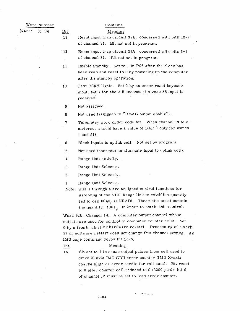
Word Number Contents
(c ont) 91-94 Bit Meaning
13 Reset input trap circuit 31B, concerned with bits 12-7
of channel 31. Bit not set in program.
12 Reset input trap circuit 31A, concerned with bits 6-1
of channel 31. Bit not set in program.
11 Enable Standby. Set to 1 in P06 after the clock has
been read and reset to 0 by powering up the computer
after the standby operation.
10 Test DSKY lights. Set 0 by an error reset keycode
input; set 1 for about 5 seconds if a verb 35 input is
received.
9 Not assigned.
8 Not used (assigned to "BIMAG output enable").
7 Telemetry word order code bit. When channel is tele-
metered, should have a value of l(bit 0 only for words
1 and 51).
6 Block inputs to uplink cell. Not set by program.
5 Not used (connects an alternate input to uplink cell).
4 Range Unit activity.
3 Range Unit Select a.
2 Range Unit Select b.
1 Range Unit Select c.
Note: Bits 1 through 4 are assigned control functions for
sampling of the VHF Range link to establish quantity
fed to cell 00468 (RNRAD). These bits must contain
the quantity, 110012 in order to obtain this control.
Word 92b, Channel 14. A computer output channel whose
outputs are used for control of computer counter cells. Set
0 by a fres h start or hardware restart. Processing of a verb
37 or software restart does not change this channel setting. An
IMIU cage command zeros bit 15-6.
Bit Meaning
15 Bit set to 1 to cause output pulses from cell used to
drive X-axis IMU CDU error counter (IMU X-axis
coarse align or error needle for roll axis). Bit reset
to 0 after counter cell reduced to 0 (3200 pps): bit 6
of channel 12 must be set to load error counter.
2 -84

Word Number Contents
(c ont ) 91-94 Bit Meaning
14 Same as bit 15, but for Y-axis (pitch).
13 Same as bit 15, but for Z-axis (yaw).
12 Bit set to 1 to cause output pulses from cell used to
drive optics trunnion or TVC yaw axis. Bit reset to
0 after counter cell reduced to 0 (3200 pps): bit 2 of
channel 12 must be set to load error counter.
11 Same as bit 12, but for optics shaft or TVC pitch axis.
10 Bit set 1 to generate gyro torquing pulses, and reset
to 0 when required number produced. Is set when
pulse torquing of gyros performed (for IMU compen-
sation or for pulse torquing in P52 or P54 followingacceptance of V06N93 display). Bit also set to 1 inGYCRS (pulse torque coarse aligning in P52/P54).
9 Bit set 1 to indicate negative gyro torquing required.
(otherwise, torquing is positive). Bit reset to 0 after
completion of routine.
8-7 Bits used to specify axis for gyro compensation
(sequence is Y, Z, X for inner, middle, outer). Pro-
gram resets to 002 when done.
002 No axis012 X-axis102 Y-axis112 Z-axis
6 Bit set 1 (it beginning of routine to generate gyro
torquing pulses) to enable gyro torquing power supply,
and left at 1 (unless a fresh start done or a caging
command).
5 Not used (assigned to entry monitoring function).
4-2 Not assigned.
1 Not used (assigned to "outlink activity").
Word 93a, Channel 30. A computer input channel for miscel-
laneous functions.
Bit Meaning
15 Bit sensed as 0 if stable member temperature within
design limits (see bit 15 of IMODES30).
14 Bit sensed as 0 if ISS has been turned on or commanded
to be turned on (see bit 14 of IMODES30).
2 -85

Word Number Contents
(c ont) 91-94 Bit Meaning
13 Bit sensed as 0 if an IMU fail indication produced (see
bit 13 of IMODES30).
12 Bit sensed as 0 if an IMU CDU fail indication produced
(see bit 12 of IMODES30).
11 Bit sensed as 0 if an IMU cage command generated by
the crew (see bit 11 of IMODES30).
10 Bit sensed as 0 if control of Saturn given to computer.
9 Bit sensed as 0 if IMU turned on and operating with no
malfunctions (see bit 9 of IMODES30).
8 Not assigned.
7 Bit sensed as 0 if an optics CDU fail indication pro-
duced (see bit 7 of OPTMODES).
6 Bit sensed as 0 if guidance reference release signal
produced: bit not sensed by program.
5 Bit sensed as 0 if liftoff signal produced (used to
cause termination of P02 and initiation of P11, a
function that can alternatively be initiated by V75E).
4 - Bit sensed as 0 if S4B separation/abort signal pro-
duced: bit not sensed by program.
3 Bit sensed as 0 when preparations for use of the SPS
engine ("SPS ready") is complete. This bit is not
sensed by the flight program.
2 Bit sensed as 0 if CM/SM separation signal produced:
bit not sensed by program.
1 Bit sensed as 0 if "ullage thrust present" (from
Saturn): bit not sensed by program.
Word 93b Channel 31. A computer input from crew control
devices, used by RCS DAP.
Bit Meaning
15 Bit sensed as 0 if computer in control of spacecraft
("G&N autopilot control"). Bit also becomes 1 if IMU
turned off, SCS spacecraft control, or translation hand
controller twisted in clockwise direction.
2 -86

Word Number
(cont) 91-94 Bit
14
13
Contents
Meaning
Bit sensed as 0 if "Free" mode selected.
Bit sensed as 0 if "Hold" mode selected. If bits 14-13
are 112, this indicates that "Automatic" mode selected.
12 Bit sensed as 0 if translation in -Z direction commanded.
11 Bit sensed as 0
10 Bit sensed as 0
9 Bit sensed as 0
8 Bit sensed as 0
7 Bit sensed as 0
6 Bit sensed as 0
commanded.
5 Bit sensed as 0
commanded.
4 Bit sensed as 0
commanded.
3 Bit sensed as 0
commanded.
2 Bit sensed as 0
commanded.
1 Bit sensed as 0
commanded.
Word
crew
Bit
if
if
if
if
if
if
translation
translation
translation
translation
translation
rotation in
in +Z direction commanded.
in -Y direction commanded.
in +Y direction commanded.
in -X direction commanded.
in +X direction commanded.
negative roll direction
if rotation in positive roll direction
if rotation in negative yaw direction
if rotation in positive yaw direction
if rotation in negative pitch direction
if rotation in positive pitch direction
94a, Channel 32. A computer
input to RCS DAP, etc.
Meaning
input channel for additional
15 Not assigned..
14 Bit sensed as 0 if "proceed key" (formerly standby
button) is depressed (see bit 14 of IMODES33).
13-12 Not assigned.
11 Bit sensed as 0 if spacecraft switch set to indicate
that LM attached: bit not used by program (cf. bit
2 of Flagword 7).
10-7 Not assigned.
2 -87

Word Number Contents
(cont) 91-94 Bit Meaning
6 Bit sensed as 0 if negative roll commanded by min-
imum impulse controller.
5 Bit sensed as 0 if positive roll commanded by min-
imum impulse controller.
4 Bit sensed as 0 if negative yaw commanded by min-
imum impulse controller.
3 Bit sensed as 0 if positive yaw commanded by min-
imum impulse controller.
2 Bit sensed as 0 if negative pitch commanded by min-
imum impulse controller.
1 Bit sensed as 0 if positive pitch commanded by mini-
mum impulse controller.
Word 94b, Channel 33. A computer input channel for hard-
ware status and command information. Bits 15-11 are flip-
flop bits ( which are reset by a channel "write" command)
that are also reset when a restart is encountered.
Bit Meaning
15 · it senscd as 0 if the computer oscillator has
stopped.
14 Bit sensed as 0 if a computer warning is pro-
duced. If bits 15-14 = 102, it is concluded
that a restart loop exists and a fresh start is
done.
13 Bit sensed as 0 if an accelerometer fail indication
produced (PIPA fail). See bit 13 of IMODES33.
12 Bit sensed as 0 if a telemetry end pulse rejected
(downlink interrupt rate excessive). See bit 12 of
IMODES 33.
11 Bit sensed as 0 if an uplink input bit is rejected, indi-
cating an excessive uplink rate. See bit 11 of IMODES33.
2 -88

Word Number Contents
(c ont) 91-94 Bit Meaning
10 Bit sensed as 0 if spacecraft switches set by crew so
as to inhibit uplink inputs from being loaded into eras-
able memory (and subsequently generating an uplink
interrupt). The bit reads a binary 1 when the "accept
uplink" signal is present at the interface.
9-8 Not assigned.
·7 Not used (assigned to "star present").
6 Not used (assigned to "star tracker on").
5 Bit sensed as 0 if computer control of optics is set.
See bit 5 of OPTMODES.
4 Bit sensed as 0 if zero optics mode is set. See bit 4
of OPTMODES. If bits 5-4 are both 1, the manual
mode is selected.
3 Not assigned.
2 Bit sensed as zero if the Range Unit data is good.
1 Not assigned.
95-97 VGTIGs. The predicted velocity (X, Y,- Z) to be gained at
TIG in reference coordinates, scaled (meters/centisecond)/
27. During Lambert burns, the DELVEET3s from pre-thrust
targeting are picked up and stored in -VGTIG. External AV
burns compute and store a rotated VG. It is calculated in
burn.programs: S40. 1 computes (X-DELV) or copies
(LAMBERT) as part of pre-thrust computations.
During P15 these words contain the following:
95 - garbage
96 - VNOW (R3 of N95) scaled (m/cs)/2 7
97 - VGTLI (R2 of N95) scaled (m/cs)/2 7
98-100 DELTA VELOCITY (X, Y, Z) at-CDH. Vector velocity change
computed (P31,P32/P72 and P33/P73)for CDHburn. Vector is.,
in reference coordinates, scaled (meters/centisecond)/27
Transformed to local vertical coordinates for display in N82
(P32/P72). Vector becomes invalid after R41 completed.
2-89

PRECEDITG PAGE BLANK NOT FILME '
2.2.2. 3 Coast and Align List
Contents
First Register
I.D. (777778)
CSM State Vector (Rx)
CSM State Vector (Ry)
CSM State Vector (Rz)
CSM State Vector (Vx)
CSM State Vector (Vy)
CSM State Vector (V Z )
CSM State Vector Time
Actual X CDU angle
Actual Z CDU angle
ADOTS roll or OGARATE
ADOTS pitch or Omega B pitch
ADOTS yaw or Omega B yaw
X Attitude error
Z attitude error
THETADX
THETADZ
TIG
STARID 1
MARKTIME 1
Y CDU angle
Z CDU angle
X CDU angle
MARKTIME2
Y CDU angle
Z CDU angle
X CDU angle
Apogee
Perigee
PACTOFF
VGTIGX
VGTIGY
VGTIGZ
REFSMMAT (R 1 C 1 )
REFSMMAT (R 1 C 2 )
REFSMMAT (R 1 C 3 )
Second Register
Synch Bits (773408)
CSM State Vector (RX )
CSM State Vector (Ry)
CSM State Vector (RZ
)
CSM State Vector (VX
)
CSM State Vector (Vy)
CSM State Vector (VZ
)
CSM State Vector Time
Actual Y CDU angle
Optics CDU trunnion angle
ADOTS roll or OGARATE
ADOTS pitch or Omega B pitch
ADOTS yaw or Omega B yaw
Y attitude error
RCS flags
THETADY
Garbage
TIG
STARID2
MARKTIME 1
Optics shaft angle
Optics trunnion angle
Garbage
MARKTIME2
Optics Shaft angle
Optics trunnion angle
Garbage
Apogee
Perigee
YACTOFF.VGTIGX
VGTIGY
VGTIGZ
REFSMMAT
REFSMMAT
REFSMMAT
}
}
Preceding page blank]2 -91
WordNumber
1
2
3
4
5
6
7
8
9
10
11
12
13
14
15
16
17
18
19
20
21
22
23
24
25
26
27
28
29
30
31
32
33
34
35
36
for lastMARKTIME 1
for last
MARKTIME 2
(R 1 C 1 )
(R 1C 2 )
(R 1C 3 )
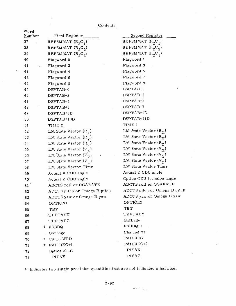
Contents
First Register
REFSMMAT (R 2 C 1 )
REFSMMAT (R 2 C 2 )
REFSMMAT (R 2 C 3 )
Flagword 0
Flagword 2
Flagword 4
Flagword 6
Flagword 8
DSPTAB+0
DSPTAB+2
DSPTAB+4
DSPTAB+6
DSPTAB+8D
DSPTAB+1OD
TIME 2
LM State Vector (RX)
LM State Vector (Ry)
LM State Vector (RZ)
LM State Vector (VX)
LM State Vector (V¥)
LM State Vector (VZ)
LM State Vector Time
Actual X CDU angle
Actual Z CDU angle
ADOTS roll or OGARATE
ADOTS pitch or Omega B pitch
ADOTS yaw or Omega B yaw
OPTION1
TET
THETADX
THETADZ
* RSBBQ
Garbage
C31FLWRD
* FAILREG+1
Optics shaft
PIPAY
Second Register
REFSMMAT (R2C 1 )
REFSMMAT (R 2 C 2 )
REFSMMAT (R 2 C 3 )
Flagword 1
Flagword 3
Flagword 5
Flagword 7
Flagword 9
DSPTAB+1
DSPTAB+3
DSPTAB+5
DSPTAB+7
DSPTAB+9D
DSPTAB+1 1D
TIME 1
LM State Vector (Rx)
LM State Vector (Ry)
LM State Vector (Rz)
LM State Vector (Vx)
LM State Vector (V
LM State Vector (V )
LM State Vector Time
Actual Y CDU angle
Optics CDU trunnion angle
ADOTS roll or OGARATE
ADOTS pitch or Omega B pitch
ADOTS yaw or Omega B yaw
OPTION2
TET
THETADY
Garbage
RSBBQ+1
Channel 77
FAILREG
FAILREG+2
PIPAX
PIPAZ
* Indicates two single precision quantities that are not indicated otherwise.
2 -92
WordNumber
37
38
39
40
41
42
43
44
45
46
47
48
49
50
51
52
53
54
55
5G
57
58
59
60
61
62
63
64
65
66
67
68
69
70
71
72
73

Contents
First Register
OGC
IGC
MGC
Flagword 10
TEVENT
LAUNCH AZIMUTH
OPTMODES
LM MASS
DAPDATR1
ERROR X
ERROR Z
WBODY (roll) or OMEGAC (roll)
WBODY (pitch) or OMEGAC (pitch)
WBODY (yaw) or OMEGAC (yaw)
REDO COUNTER.
Desired FINAL CDU Y
IMODES 30
Channel 11
Channel 13
Channel 30
Channel 32
DSPTAB+0
DSPTAB+2
DSPTAB+4
DSPTAB+6
DSPTAB-+8D
DSPTAB+1 OD
Second Register
OGC
IGC
MGC
Flagword 11
TEVENT
LAUNCH AZIMUTH
HOLDFLAG
CM MASS
DAPDATR2
ERROR Y
Garbage
WBODY (roll) or OMEGAC (roll)
WBODY (pitch).or OMEGAC (pitch)
WBODY (yaw) or OMEGAC (yaw)
Desired FINAL CDU X
Desired FINAL CDU Z
IMODES 33
Channel 12
Channel 14
Channel 31
Channel 33
DSPTAB+1
DSPTAB+3
DSPTAB+5
DSPTAB+7
DSPTAB+9D
DSPTAB+1 lD
2 -93
WordNumber
74
75
76
77
78
79
80
81
82
83
84
85
86
87
88
89
90
91
92
93
94
95
96
97
98
99
100
00Sea

PRECIXING PAGE BLANK NOT FTLMED-
2.2.2.4 Coast and Align List
Word Number Contents
la I. D. word for this list. It will contain 777778.
lb Synch bits, 773408.
2-18 Same as words 2-18 on the Powered List.
19 STAR ID1, 2. The star I. D. 's associated with the sighting vectors
in words 21-23 and 25-27. Each star I. D. will be the octal
equivalent of the CMC star catalogue number multiplied by six.
Each register is scaled (star number x 6)/214
Example:
Star Cat. Number Downlink Star I. D.
Alpha Tauri 118 668
0o
20 MARKTIME1. The time of the mark (TIME2, TIME1) associated
with the data described in words 21-23a, scaled centiseconds/22 8 .
21-23a SIGHTING DATA SET1. These five registers contain, in the
following order: YCDU angle, optics shaft angle, ZCDU angle,
optics trunnion angle and XCDU angle. This data is valid at
MARKTIME1 and is associated with the star indexed by BESTI
(word 19a). XCDU, YCDU, ZCDU and the optics shaft angle are
treated as unsigned 15-bit fractions, scaled degrees/360. The
optics trunnion angle is scaled (degrees-19. 7754)/45. The bias,
19. 7754, is programmed-in.
23b Garbage.
24 MARKTIME2. The time of the mark (TIME2, TIME1) associated
with the data described in words 25-27a, scaled centiseconds/22 8 .
25-27a SIGHTING DATA SET 2. Same as words 21-23a of this list except
that this set is associated with MARKTIME2 and Star ID2 indexed
by BESTJ (word 19b).
27b Garbage.
28 APOGEE. The altitude of the apogee above a reference radius
(pad radius - earth, landing site - moon), scaled meters/22 9 .
Calculated in R30 only.
Preceding page blank2-95

Word Number--
29
30
31-33
34-63
64a
64b
Contents
PERIGEE. The altitude of the perigee above a reference radius
(pad radius - earth, landing site - moon) scaled meters/2 2 9 .
Calculated in R30 only.
Same as Word 28 of the Powered List.
Same as words 95 - 97 of the Powered List.
Same as words 34 - 63 of the Powered List.
OPTION1. The option code which is displayed in R1 in conjunction
with a flashing V04 N06 to request the astronaut to load into R2 the
option he desires.
OPTION2. The astronaut-selected option which was loaded into R2
as a result of the displayed OPTION1 code.
The OPTION1 and OPTION2 codes, scaled in octal, are as follows:
OPTION 1 Code
00001 (during P52, P54)
00002 (during P2
00004
00007 (during P3
00024 (during P'
65
66-73
74-76
77
78
79
80-94
P29)
37)
20)
Purpose
Specify IMU Orientation
Specify Vehicle
Specify State of Tracking
Specify Propulsion System
Specify Tracking Option
OPTION2 Code (Astronaut Input)
1=Preferred 2 =Nominal3=REFSMMAT 4=Landing site
1=This Vehicle 2=Other Vehicle
1= Partial 0= Full
1=SPS 2=RCS
0= Rendezvous, VECPOINT1=Celestial body, VECPOINT2= Rotation4=Rendezvous, 3-axis5=Celestial body, 3-axis
TET. The time of state vector being integrated or the time to
which the last state vector was integrated. It is stepped by half-
time-step increments (plus or minus) whenever integration is being
done. It is scaled, centiseconds/22 8
Same as words 66-73 of the Powered List.
OGC, IGC, MGC. During R55, the X, Y, and Z gyro torquing
angles. During coarse align, in P52 and P54, the desired gimbal
angles (outer, inner & middle), scaled degrees/360.
Same as word 77 of the Powered List.
Same as word 78 of the Powered List.
LAUNCHAZ: The clockwise angle from true north to the IMU
stable member X axis, measured in the local horizontal plane
and scaled degrees/360. The expected angles will range from
+72° to +108 ° (approx. ). The item is pad loaded and may be re-
loaded during P02, gyrocompassing program, via Verb 78E.
Same as words 80-94 of the Powered List.
95-100 Same as words 45-50 of the Powered List.
tThis change accomplished in Revision 14 but PCR 1054 notation omitted.
COLOSSUS 3 2-96
GSOP # R-577 PCR # 1049 Rev. 15 Date NOV 7'

Rendezvous and Prethrust List
Contents
First Register
I. D. (77775 8)
CSM State Vector (RX)
CSM State Vector (Ry)
CSM State Vector (RZ)
CSM State Vector (VX)
CSM State Vector (Vy)
CSM State Vector (VZ)
CSM State Vector Time
Actual X CDU angle
Actual Z CDU angle
ADOTS roll or OGARATE
ADOTS pitch or Omega B pitch
ADOTS yaw or Omega B yaw
X attitude error
Z attitude error
THETADX
THETADZ
TIG
TF Lambert
RTARGX
RTARGY
RTARGZ
VHF TIME
MARK TIME
Y CD U angle
Z CDU angle
X CDU angle
VHF MARKS
TPI TIME
ECSTEER
DELVTPF (Magnitude)
CDH TIME
CSI TIME
TPF Time
DELVSLV X
DELVSLV Y
DELVSLV Z
Second Register
Synch Bits (773408)
CSM State Vector (RX)
CSM State Vector (Ry)
CSM State Vector (RZ)
CSM State Vector (VX)
CSM State Vector (Vy)
CSM State Vector (VZ)
CSM State Vector Time
Actual Y CDU angle
Optics CDU trunnion angle
ADOTS roll or OGARATE
ADOTS pitch or Omega B pitch
ADOTS yaw or Omega B yaw
Y attitude error
RCS flags
THETADY
Garbage
TIG
TF
Lambert
RTARGX
RTARGY
RTARGZ
VHF TIME
MARK TIME
Optics shaft angle
Optics trunnion angle
VHF-. Range
OPTIC MARKS
TPI TIME
Garbage
DELVTPF (Magnitude)
CDH TIME
CSI TIME
TPF Time
DELVSLV X
DELVSLV Y
DELVSLV Z
2-97
WordNumber
1
2
3
4
5
6
7
8
9
10
11
12
13
14
15
16
17
18
19
20
21
22
23
24
25
26
27
28
29
30
31
32
33
34
35
36
37
2.2.2.5
;2

Contents
First Register
Range
Range Rate
Flagword 0
Flagword 2
Flagword 4
Flagword 6
Flagword 8
DSPTAB+0
DSPTAB+2
DSPTAB+4
DSPTAB+6
DSPTAB+8D
DSPTAB+1OD
TIME 2
LM State Vector (RX)
LM State Vector (Ry)
LM State Vector (RZ)
LM State Vector (VX)
LM State Vector (Vy)
LM State Vector (VZ)
LM State Vector Time
Actual X CDU angle
Actual Z CDU angle
ADOTS roll or OGARATE
ADOTS pitch or Omega B pitch
ADOTS yaw or Omega. B yaw
OPTION 1
TET
THETADX
THETADZ
* RSBBO
Garbage
* C31FLWRD
* FAILREG+1
Optics shaft
PIPAY
CDH Delta Altitude
Central Angle
Second Register
Range
Range Rate
Flagword 1
Flagword 3
Flagword 5
Flagword 7
Flagword 9
DSPTAB+1
DSPTAB+3
DSPTAB+5
DSPTAB+7
DSPTAB+9D
DSPTAB+11D
TIME 1
LM State Vector (RX)
LM State Vector (Ry)
LM State Vector (RZ)
LM State Vector (VX)
LM State Vector (Vy)
LM State Vector (VZ )
LM State Vector Time
Actual Y CDU angle
Optics CDU trunnion angle
ADOTS roll or OGARATE
ADOTS pitch or Omega B pitch
ADOTS yaw or Omega B yaw
OPTION2
TET
THETADY
Garbage
RSBBQ+1
Channel 77
FAILREG
FAILREG+2
PIPAX
PIPAZ
CDH Delta Altitude
Central Angle
* Indicates two single precision quantities that are not indicated otherwise.
2-98
WordNumber
38
39
40
41
42
43
44
45
46
47
48
49
50
51
52
53
54
55
56
57
58
59
60
61
62
63
64
65
66
67
68
69
70
71
72
73
74
75

Contents
First Register
Spare
DELVEET3 X
DELVEET3 Y
DELVEET3 Z
OPTMODES
LM MASS
DAPDATR1
ERROR X
ERROR Z
WBODY (roll) or OMEGAC (roll)
WBODY (pitch) or OMEGAC (pitch)
WBODY (yaw) or OMEGAC (yaw)
REDO COUNTER
Desired FINAL CDU Y
IMODES 30
Channel 11
Channel 13
Channel 30
Channel 32
RTHETA
GEODETIC LAT
LONG
V PRED
GAMMA(EI)
Flagword 10
Second Register
Spare
DELVEET3 X
DELVEET3 y
DELVEET3 Z
HOLDFLAG
CM MASS
DAPDATR2
ERROR Y
Garbage
WBODY (roll) or OMEGAC (roll)
WBODY (pitch) or OMEGAC (pitch)
WBODY (yaw) or OMEGAC (yaw)
Desired FINAL CDU X
-Desired FINAL CDU Z
IMODES 33
Channel 12
Channel 14
Channel 31
Channel 33
RTHETA.
GEODETIC LAT
LONGV PRED
GAMMA(EI)
Flagword 11
2-99
WordNumber
76
77
78
79
80
81
82
83
84
85
86
87
88
89
90
91
92
93
94
05
96
97
98
99
100
000

pPEC EDI3G PAGE BLANK NOT FILM
2. 2.2. 6 Rendezvous and Prethrust ListWord Number Contents
la I.D. word for thislist. It will.contain 777758.
lb Synch bits, 773408.
2-22 Same as words 2-22 on Powered List.
23 VHF TIME. The time (TIME2, TIME1) of the last VHF Range
mark, scaled centiseconds/2 28. This item is calculated each
time the VHF Range is read. It is also used to determine if one
minute has elapsed since the last mark was processed and to
integrate the state vector to the mark-time.
24 OPTICS MARKTIME. The time of mark (TIME2, TIME1)
associated with the data described in words 25-27a, scaled28
centiseconds/2 .
25-27a SIGHTING DATA. These five registers contain, in the following
order: YCDU angle, optics shaft angle, ZCDU angle, optics
trunnion angle and XCDU angle. This data is valid at the time
an optics mark is taken on the LM vehicle during rendezvous
tracking (P20). XCDU, YCDU, ZCDU and optics shaft angle are
unsigned 15-bit fractions, scaled degrees/360. The trunnion angle
is a 14-bit signed fraction scaled, (degrees -19. 7754)/45 (two's
' complement). The bias, 19. 7754, is programmed-in.
27b VHF RANGE. (Raw Data). The range from the CSM to the LM
as measured by the VHF range link, using the Rendezvous
Tracking Data Processing Routine. This quantity is a 15-bit
integer with the least significant bit equal to 0. 01 nmi. (multiply
by 18. 52 to obtain meters). Whenever the VHF Range Flag is
found to be set, the routine (R22) reads the range value if at least
60 seconds have expired since the time of last reading. If so, the
tVHF is updated to the present time and a VHF range reading
made. It is assumed, for practical purposes, that the range data
is acquired at this present tVHF but there actually is a very small
time delay.
28a VHF MARKS. The number of VHF ranging marks incorporated
into the state vector since the initialization of P20, scaled 2 - 14.
This item is used in the N45 display (two most significant digits
of Ri) and has a range in that display of 0 to 99 (modulo 100).
VHFCNT is incremented each time a VHF ranging mark is incor-
porated (approx. 1/min if P20 is operating, VHF ranging is on and
RANGFLAG, VHFRFLAG, UPDATFLG and TRACKFLG are set).
Set to 0 by Fresh Start, P37, and when the W-matrix is re-initialized.
2-101 receding age bla

Word Number
28b
29
30a
30b
31
32
Contents
OPTIC MARKS. The number of optic marks incorporated into the
state vector since the initialization of P20, scaled 2-14. This item
is used in the N45 display (two least significant digits of Ri) and
has a range inthatdisplayof 0 to 99 (modulo 100). TRKMKCNT is
incremented each time an optics mark is incorporated. The frequency
depends uponthe astronaut because marking is a manual operation.
Set to 0 as in word 28a.
TPI TIME. The time of ignition for the Rendezvous programs,
scaled centiseconds/22 8 . It is an input to P31, P32, P34, P72
and P74. It can be updated by P34 or P74 if elevation angle is
provided.
ECSTEER. A pad-load erasable which may be used by P40 to set
CSTEER, the constant "c" in the cross-product steering equation:
Am = cbAt - Av, and in certain prethrust computations for P40/41.
It is scaled as a 14-bit fraction/4. P34 and P35
will set ECSTEER = 1. 0. P37 will set ECSTEER = 0. 5.
Values for "C" from -4. 0 to +4. 0 (less 1 bit) can be
handled. The MIT standard is 1. 0, except for P37 where
0. 5 is used. Once set up prior to a burn, ECSTEER should be
constant throughout the burn and post-burn sequences. ECSTEER
is also set to 1 by P31, P32, P33 and P36. Although this setting
is not functional, it would destroy any previously uplinked value.
Garbage.
DELVTPF. The difference between the absolute velocities of the
passive and active vehicles at intercept time [ ABVAL (VPASS4 -
VTPRIME)I, scaled (meters/centisecond)/27. This quantity is
calculated by P34 and P74o
CDH Time. The time of ignition of the CDH maneuver. Used to
initialize state vector for CDHMVR subroutine. Calculated each
iteration of CSI/A subroutine in P31, P32 and P72. Scaled centiseconds /
228, referenced to computer clock.
2-102

Word Number
33
34
35-37
38
39
Contents
CSI Time. The time of ignition for the CSI maneuver. Used in
tP31, P32 and P72 calculations. Input by astronaut by V25N11.
Scaled centiseconds/22 8 , referenced to computer clock. During
multiple CSI sequences in MINKEY, the MINKEY controller updates 0
this cell to the time of the next CSI maneuver. 80
TPF Time. The time of intercept for the various rendezvous
programs, scaled centiseconds/22 8 . It is one of the variables
used in the determination of the required delta velocity for a
rendezvous maneuver. It is calculated in P34/P74 and inputted
to the midcourse programs, P35/P75.
P30 DELV's. An impulsive Delta V in the local vertical coordi-
nates of the active vehicle at the time of ignition specified by the
astronaut (V06N8 1) or uplink and scaled (meters/centisecond)/27 .
The local vertical coordinate system may be either earth-centered
or moon-centered. There is no flagbit to indicate the origin poinr.
The P30 AV vector is rotated into a basic reference coordinate
system for use by P40 or P41.
RANGE. This parameter is involved in two areas, R31/R34 and
R36. In either category it is scaled, meters/22 9 . In R31/R34,
RANGE is the magnitude of the difference between the two vehicles'
(CSM-LM), radius vectors. In R36, RANGE represents the out-
of-plane position for the CSM and is computed as Y = rC. o
IUNIT(VL xrL) .· This item is calculated in P79 or whenever R31, R34 8or R36 is selected by the astronaut via V83, V85, or V90. The
displayed value can range from 000. 00 nmi. to 999. 99 nmi. Once
the routine is selected, RANGE is recomputed in R31/R34 until
program termination ("PROCEED"); in R36 it is necessary to
"RECYCLE" in order to have the value recomputed. The update
rate in R31 and R34 is a function of what other jobs are running.
RRATE. This parameter is involved in two areas, R31/R34 and
R36. It is scaled (meters/centisecond)/27 . In R31/R34 it is
defined as the range rate between the two vehicles (CSM-LMI) and
is computed as R = (VL - VC) * {UNIT (RL - _Rc)} . A negative
quantity indicates closing. In R36, RRATE represents velocity
for CSM in the sense of Y = VC
UNIT (VLxrL) This item A
is calculated inP79 orwhenever R31, R34, orR36is selectedbythe °
astronaut using verbs V83, V85, or V90. The displayed value
can range from 0000. 0 fps to 9999. 9 fps. It is recomputed
2-103

Word Number
40-63
64, 65
66-73
74
75, 76
77-79
80-94
95
96
Contentsin R31/R34 until program termination ("PROCEED"). In R36
it is necessary to RECYCLE in order to up'date the value,
which is valid for an astronaut-selected time. The update rate
in R31 and R34 is a function of what other jobs are running.
Same as words 40-63 of the Powered List.
Same as words 64, 65 of the Coast and Align List.
Same as words 66-73 of the Powered List.
CDH Delta Altitude. The altitude between the active and passive
vehicle orbits at CDH time. Used for display and other CDHMVR
calculations. Calculated each iteration of CDHMVR subroutine; oncein P33/P73, numerous times possible in P31, P32/P72. Earth- or moon-
centered altitude depending upon whether bit 12 of flagword 8
(CMOONFLG) is zero or one, respectively. Scaled meters/22 9 .
Same as words 75 and 76 of Powered List.
DELVEET3s. The impulsive DELTA V (X, Y,:Z) calculated
via the Lambert routine, scaled (meters/centisecond)/27. Thesequantities are based on the offset-target vector, time of
ignition, and transfer time. The reference coordinates may be
either moon- or earth-centered. The system in use is indicated
by the contents of erasable register, RTX2. If RTX2 = 0, the-~-.ystem is earth-centered but, if RTX2 = 2, the system is moon-
centered.
Same as words 80-94 of the Powered List.
Word 95 serves two areas, RTHETA in R31/R34 and RRATE2in R36,
RTHETA. In R31/R34 it is the angle from the local horizontalplane to either the CSM X-body axis (Noun 54 flashing) or to the
SXT line of sight (Noun 53 flashing). The scaling is in degrees/360. This item is calculated in P79 or whenever R31 or R34is selected by the astronaut via V83 or V85. It is computed
in R31/R34 until program termination ("PROCEED"). The
update rate is a function' of what other jobs are running.
RRATE2. Same as word 39 for R36 except velocity is for LM.
LAT (SPL). The latitude of the landing site (earth), scaled
degrees/360. It is used only for DSKY display and is calculated
and displayed at the end of both the conic phase and also the preci-
sion phase of the Return to Earth program. The range of valuesis from -90 ° to +90 ° . A negative value'indicates south of the
equator, whereas a positive one denotes north of the equator.
2-104

Word Number Contents
97 LNG (SPL). The longitude of the landing site (earth), scaled
degrees/360. The range of values is from -180 ° to +1800. A
negative quantity indicates west of Greenwich, whereas a positive
one denotes east of Greenwich. This item is used for DSKY
display only and is calculated and displayed at the end of both the
conic phase and the precision phase of the Return to Earth
program.
98 VPRED. The predicted velocity magnitude at an entry altitude of
400, 000 ft above the Fischer Ellipsoid, scaled (meters/centi-
second)/2 . The range of values is from +75 meters/centisecond
to +115 meters/centisecond. This item is used for DSKY display
only and is calculated and displayed at the end of both the conic
phase and the precision phase of the Return to Earth program.
99 GAMMAEI. The flight path angle between the inertial velocity
vector and the local horizontal at the entry interface altitude of
400, 000 ft. above the Fischer Ellipsoid, scaled degrees/360.
The range of values runs from -1 ° to -70 and is used for display
only. A negative value indicates that the flight path is below the
horizontal plane. This item is calculated and displayed at the end
of both the conic and precision phases of the Return to Earth pro-
gram.
100 Same as word 77 of the Powered List.
2-105

PRECEDING PAGE BLANK NOT FILhMETEntry and Update List
C ontents
First Register
I. D. (777768)
CSM State Vector (RX)
CSM State Vector (Ry)
CSM State Vector (RZ)
CSM State Vector (VX)
CSM State Vector (Vy)
CSM State Vector (VZ)
CSM State Vector Time
Actual X CDU angle
Actual Z CDU angle
ADOTS roll or OGARATE
ADOTS pitch or Omega B pitch
ADOTS yaw or Omega B yaw
X attitude error
Z attitude error
THETADX
THETADZ
ENTRY DAP MODE
QREL (pitch rate)
L/D1I
* UPBUFF
* UPBUFF+2
* UPBUFF+4
* UPBUFF+6
* UPBUFF+8D
* UPBUFF+1OD
* UPBUFF+12D
* UPBUFF+14D
* UPBUFF+16D
* UPBUFF+18D
COMPNUMB
UPVERB
Roll error
LATANG
RDOT
THETAH
LAT (SIPL)
LONG (SPL)
Second Register
Synch Bits (773408)
CSM State Vector (RX)
CSM State Vector (Ry)
CSM State Vector (RZ)
CSM State Vector (VX)
CSM State Vector (Vy)
CSM State Vector (VZ)
CSM State Vector Time
Actual Y CDU ingle
Optics CDU trunnion angle
ADOTS roll or OGARATE
ADOTS pitch or Omega B pitch
ADOTS yaw or Omega B yaw
Y attitude error
RCS flags
THETADY
Garbage
PREL (roll rate)
RREL (yaw rate)
L/D1
UPBUFF+1
UPBUFF+3
UPBUFF+5
UPBUFF+7
UPBUFF+9D
UPBUFF+l ID
UPBUFF+13D
UPBUFF+1 5D
UPBUFF+17D
UPBUFF+19D
UPOLDMOD
UPCOUNT
Roll angle
LATANG
RDOT
THETAH
LAT (SPL)
LONG (SPL)
* Indicates two single precision quantities that are not indicated otherwise.
Preceding page blank 17
2.2.2.7
WordNumber
I
2
3
4
5
6
7
8
9
10
11
12
13
14
15
16
17
18
19
20
21
22
23
24
25
26
27
28
29
30
31
32
33
34
35
36
37
38

Contents
First Register
ALPHA
Flagword 0
Flagword 2
Flagword 4
Flagword 6
Flagword 8
DSPTAB+0
DSPTAB+2
DSPTAB+4
DSPTAB+6
DSPTAB+8D
DSPTAB+1OD
TIME 2
PIPTIME1
DELVX
DELVY
DELVZ
TTE (EMS)
Vn.0
VPRED (El)
Act'lal X CDU angle
Actual Z CDU angle
ADOTS roll or OGARATE
ADOTS pitch or OMEGA B pitch
ADOTS yaw or OMEGA'B yaw
OPTION 1
TET
ERROR X
ERROR Z
THETA DY
ENTRY DAP MODE
QREL (pitch rate)
UPBUFF
UPBUFF+2
UPBUFF+4
UPBUFF+6
UPBUFF+8D
.Second Register
BETA
Flagword 1
Flagword 3
Flagword 5
Flagword 7
Flagword 9
DSPTAB+1
DSPTAB+3
DSPTAB+5
DSPTAB+7
DSPTAB+9D
DSPTAB+1 1D
TIME 1
PIPTIME1
DELVX
DELVY
DELVZ
TTE (EMS)
VrO
VPRED (EJ)
A tual Y CDU angle
Optics CDU trunnion angle
ADOTS roll or OCrARA.TE
ADOTS pitch or OMEGA B pitch
ADOTS yaw or OMEGA B yaw
OPTION2
TET
ERROR Y
THETADX
THETADZ
PREL (roll, rate)
RREL (yaw rate)
UPBUFF+1
UPBUFF+3
UPBUFF+5
UPBUFF+7
UPBUFF+9D
2-10o8
WordNumber
39
40
41
42
43
44
45
46
47
48
49
50
51
52
53
54
55
56
57
58
59
60
61
62
63
64
65
66
67
68
69
70
71
72
73
74
75

Contents
First Register
UPBUFF+1OD
UPBUFF+12D
UPBUFF+14D
UPBUFF+16D
UPBUFF+18D
LM MASS
DAPDATR1
Roll Angle
OPTMODES
WBODY (roll) or OMEGAC (roll)
WBODY (pitch) or OMEGAC (pitch)
WBODY (yaw) or QMEGAC (yaw)
REDO COUNTER
Desired FINAL CDU Y
IMODES 30
Channel 11
Channel 13
Channel 30
Channel 32
* RSBBO
Garbage
* C31FLWRD
* FAILREG+i
Flagword 10
GAMMA (EI)
Second Register
UPBUFF+I 1D
UPBUFF+1 3D
UPBUFF+1 5D
UPBUFF+17D
UPBUFF+19D
CM MASS
DAPDATR2
Roll Command
HOLDFLAG
WBODY (roll) or OMEGAC (roll)
WBODY (pitch) or OMEGAC (pitch)
WBODY (yaw) or OMEGAC (yaw)
Desired Final CDU X
Desired FINAL CDU Z
IMODES 33
Channel 12
Channel 14
Channel 31
Channel 33
RSBBQ+ 1
Channel 77
FAILREG
FAILREG+2
Flagword 11
Range for Initialization
* Indicates two single precision quantities that are not indicated otherwise.
2-109
WordNumber
76
77
78
79
80
81
82
83
84
85
86
87
88
89
90
91
92
93
94
95
96
97
98
99
100

PRzECEDiNG PAGE BLANK NOT FILMED2. 2. 2.8 Entry and Update List
Word Number Contents
la I. D. word for this list. It will contain 777768.
lb Synch bits. It will contain 773408.
2-17 Same as words 2-17 on the Powered List.
18a ENTRY DAP MODE. A 4-position switch specifying branching
in ENTRY DAP, scaled 2 1 4
Set to "-1" (777768) if entry equations sense drag in excessof 0. 05 g.
Set to "-0" (777778) if the ALFA angle (pitch attitude) magni-
tude is greater than 135 ° .
Set to "+1" (000018) if the ALFA angle magnitude is in the
range 45°-135 ° .
Set to "+0" (000008) if the ALFA angle is less than 45 ° .
The expected value sequence would be, +l--+0--1+--l. The value,
-0,is not generally expected. This item is calculated each 0. 1
second after the DAP is turned on in P62. Flagword 6, bits 12
and 2, indicates an active DAP.
18b, 19 PREL, QREL, RREL. The single-precision roll, pitch and yaw
rates, components of the CM angular velocity vector along the
body X, Y, and Z axes and scaled.(degrees/sec)/1800. All are
corrected for YE if YE > YE min. The expected range of values
would be: PREL ± 20 0 /sec, QREL ± 4 0 /sec, RREL - ± 17 0 /sec.
These quantities are calculated each 0. 1 sec after the DAP is
turned on in P62.
The functioning is indicated by non-zero values in both bit 1 and
bit 2 of flagword 6.
20 L/D1. The commanded value, of lift-to-drag ratio used in Reentry
Steering to provide Roll Command, scaled 20. It is computed when-
ever lateral logic is exercised, normally each 2 seconds after the
initiation of P64 until the velocity becomes less than 1000 ft/sec
in P67. The value range should be equal to, or less than, 1. 0.
It is omitted in P66. LAD is pad loaded.
Preceding page blank-2-11l
C

Word Number
21-30
31a
Contents
UPBUFF's. These twenty registers, UPBUFF through
UPBUFF +19D, contain the uplinked octal components in the
transmitted order. If the update is composed of less than
twenty quantities, the remaining registers will contain garbage.
COMPNUMB. The total number (octal) of components the update
program expects to receive. For a Verb 71 or a Verb 72 update,
COMPNUMB will be set equal to the index value.
UPOLDMOD. This is the number of the CMC program which
was interrupted by P27, the update program. It will indicate
program 0, 2, 20, or Fresh Start (-08).
UPVERB. The least significant digit of the verb number which
was selected to initiate a desired CMC update.
UPCOUNT. The octal identifier of the next quantity that the up-
date program expects to receive. As each quantity goes into
UPBUFF, UPCOUNT will be incremented by one, until it is
equal to COMPNUMB. It will not change during a line-by-line
correction of the data load.
ROLL ERROR. The CM roll attitude error in body axes generated
by the DAP and displayed on the FDAI needle, scaled degrees/360.
The error is integrated each 0. 1 sec between 2-second DAP up-
dates. This quantity is the same as the item, AK, except for the
scale factor, and is active only after the DAP is turned on in P62.
A one in bit 12 of flagword 6 indicates such activity.
ROLL ANGLE. The roll attitude angle used by ENTRY DAP,
scaled degrees/180. It is the first Euler rotation of the CM body
triad about the negative relative velocity vector -UVA, along
which UBX points. The value ranges ± 1800, is calculated after
the DAP is turned on in P62 and is updated each 0. 1 second during
its operating period. Operation is indicated by a non-zero in
bit 12 of flagword 6.
LATANG. The lateral range expressed as an angle, scaled
radians/4. It will range at less than 200 nmi and is calculated
each 2 seconds after the initiation of P63 until the end of P67.
2-112
GSOP 0 R-577 PCR # 1051 Rev, 15_ ___~~~~~1
31b
I32a
32b
33a
33b
34

Word Number Contents
35 RDOT. Altitude rate. The radial component of velocity (negative
if descending), scaled (feet/sec)/(2 x 25766. 1973). This is a
scalar component calculated in earth-centered reference coordi-
nates. If bit 9, flagword 6 (RELVELSW) is zero, the velocity
used is inertial. If bit 9, flagword 6 is a one, a velocity relative
to air mass is used. The expected range of values runs from
less than -7000 ft/sec to +1000 ft/sec and is calculated each
2 seconds after P63 until the end of P67.
36 THETAH. The range between the present position and the esti-
mated landing site, expressed as an angle and scaled, degrees/
360. The expected value is less than 180° It is calculated each
2 seconds after P63 until the end of P67. It is used in P61 for
computing EMS display but is not on the Powered Flight downlist,
however.
37 LAT(SPL).- The geodetic latitude of the entry target, scaled
degrees/360. A positive quantity denotes North while a negative
quantity indicates South. This parameter is pad loaded or DSKY
loaded when P61 or P62 is in progress. It is also computed in
P37 (Return to Earth) and displayed.
38 - - LONG(SPL). The longitude of the entry target scaled, degrees!
360. A positive quantity indicates East while a negative quantity
denotes West. This parameter is pad loaded or DSKY loaded
when P61 or P62 is in progress. It is also computed in P37 (Return
to Earth) and displayed.
39a ALPHA. The pitch attitude angle, used by ENTRY DAP and scaled,
degrees/180. It is the third rotation of the CM body'triad in the
Euler sequence R, a, a' , and is about UBY. The value range is
± 18CPand is calculated each 0. 1 second after the DAP is turned
on in P62. Operation of such is indicated by a non-zero value in
bit 12, flagpvord 6. (Bits 1 and 2 are also non-zero.)
39b BETA. The yaw attitude angle, used by ENTRY DAP and scaled
degrees/180. It is the second rotation of the CM body triad in the
Euler sequence R, a , e , and is about UBZ. The range is ± 90 °
and is calculated each 0. 1 second after the DAP is turned on in P62.
This state is indicated by a non-zero value in bit 12, flagword 6.
(Bits 1 and 2, flagword 6, will also be non-zero. )
2-113

Word Number Contents
40-51 Same as words 40-51 of the Powered List.
52 PIPTIME1. The time (T2/T1) at which the PIPAs are read, scaled
centiseconds/228. Integration stores the PREREAD state vector
time in anticipation of reading PIPAs at that time. PIPASR stores
TIME2/TIME1 every two seconds during Average g.
53-55 DELVs. The sampled X, Y, & Z PIPA accumulations (velocity in-
crements) with compensation for PIPA bias and scale factor errors.
These quantities are in the stable member coordinate system and14
are scaled, (cm/sec)/(5. 85 x 2 ). Calculation takes place every
two seconds during AVE G. The variation with time and the range
of values depend on the acceleration level and compensation. There
is a zeroing of all low-order components and a momentary zeroing
of DELVY and DELVZ prior to the loading of PIPA contents into
respective high-order words (part of READACCS, or REREADAC
task). If no restarts occur the momentary zeroing would not appear
on the downlink. PIPA compensation follows in Servicer job (in-
hinted, so that all or no PIPA compensation shows up).
56 TTE(EMS). The time required to traverse the conic path from
the present position to the specified EMS altitude above the
Fischer ellipsoid, expressed as a negative number, counting down
and scaled, centiseconds/2 . The value is calculated
in P61. It will be decremented every two seconds
thru P63 and displayed via N63. (See Note 1).
57 VIO. The predicted entry velocity at the EMS altitude above the
Fischer radius along a conic path from the present position, scaled
(meters/centisecond)/2 . The value will be approximately
38, 000 ft/s and be calculated in P61. (See Note 1).
58 VPRED(EI). The predicted entry velocity at 400K feet above the
Fischer radius along a conic path from the present position, scaled
(meters/centisecond)/2 . The value will be approximately
38K ft/s and be calculated in P61. (See Note 1).
(Note 1: If the Recycle option (V32E) of N63 in P61 is exercised, this quantity
is recalculated using the current state vector. However, only the result of the
final calculation will appear on the ENTRY and UPDATE list).
2 -114

Word Number59-6364-6566-67a
67b-68
69-70
71-80
81-82
83a
83b
84
85-94
99
100a
100b
ContentsSame as words 59-63 on the Powered List.Same as words 64-65 on the Coast and Align List.Same as words 83, 84a on the Powered List.
Same as words 16, 17a on the Powered List.
Repeat of words 18-19 of this list.
Repeat of words 21-30 of this list.
Same as words 81-82 on the Powered List.
Same as word 33b of this list.
ROLL COMMAND. The most significant half of roll attitude
command issued by Entry Guidance equations and used by the
Entry DAP, scaled degrees/360. The angle is defined as a
rotation about the negative relative velocity vector, -VREL.
The value will range ± 180°and is initially set in P62, based on
HEADSUP, and holds until the drag exceeds 0. 05 g. The quantity
will be changed each 2 seconds after P64 until P67.
Same as word 8) on the Powered List.
Same as words 85-94 on the Powered List.
Same as ;words 68-71 on the Powered List.
Same as word 77 on the Powered List.
GAMMA(EI). The conic flight path angle between the inertial
velocity and the local horizontal at the entry interface altitude
of 400, 000 ft above the Fischer ellipsoid, scaled degrees/360.
A minus quantity indicates that the flight path is below the
horizontal plane. This item is calculated in P61. (See Note 1).
RANGE for INITIALIZATION. The predicted range angle from
the EMS altitude above Fischer radius to target along conic from
present position, scaled degrees/360. This value is calculatedin P61.' (See Note 1).
REENTRY and DAP SHARING of DOWNLIST REGISTERS
Words 11-13 ADOT, ....+5 =
Word 16a THETADX
XPIPBUF PIPA Buffers for TM during
YPIPBUF ENTRY. PIPs filed here every
ZPIPBUFJ 0.5 second.
XOLDBIJF1 Contain PIPA value
YOLDBUF' previously in PIPBUF.
ZOLDBUiFJ
Scaled (centimeters/second)/(5. 85 x 214)o
= QAXERR, Pitch attitude error. Scaled dearees/180.2-115

= RAXERR, Yaw attitude error. Scaled degrees/180r
Word 17 a THETADZ
Word 17b Garbage
= Q7, high order register
2 Q7, low order register
Minimum drag for
UPCONTROL, scaled
(ft/sec2 )/805.
Word 2 1a UPBUFF
Word 21b UPBUFF +1
iWords 22a-29a UPBUFF +2
... +16D
= CMTMTIME, Time at which body-rate list was last
initialized. Scaled centiseconds/ 214.
SW/NDX, Combined switch and index associated with
FDAI display and TM. See COLOSSUS GSOP Section 3.
Scaled 2-14.
Body rates in the sequence, PREL, QREL, RREL,
PREL, QREL, RREL, etc. Scaled (degrees/sec)/1800.
Words 29b, 30a UPBUFF +17D,
... +18D = V1, initial velocity for UPCONTROL. Scaled
(ft/sec)/(2 x 25766. 1973).
Word 30b UPBUFF +19D = AO (high order register) initial drag for UPCONTROL.
Scaled (ft/sec 2 )/805. 0.
Word 56 TTE, . . . +1 = During P64 through P67: L/DCALC, onboard estimate
of L/D ratio. Scaled 20 (max. value of 1.0). Exception:
garbage if . 05GSW = 0 (bit 3 of Flagword 6).
This will occur in P66 if a ballistic trajectory is flown.
Word 57 VIO, ... +1 = LEWD, UPCONTROL reference, L/D. Scaled 20
(max. value of 1.0).
Word 58 VPRED, ... +1 = VL, exit velocity for UPCONTROL. Scaled (ft/sec)/
(2 x 25766. 1973).
Word 66a ERRORX = VDT/180, preselected drifting rate used by Roll DAP
(0 = DAP in dead zone). Scaled (deg/sec)/90.
Word 66b ERRORY =-VT/180E, minus roll rate used by the Roll DAP
update cycle. Scaled (-deg/sec)/90.
Word 67a ERRORZ LCX/360, the roll error (prior to reflection, if any)
used by two second Roll DAP update cycle. Scaled
deg/ 360.
The value in this cell is used to initialize Roll
Error (word 33a); however, Roll Error is updated
each 0. 1 second.
2 -116
Word 16b THETADY

Words 85-87 WBODY, ...+5
= ASKEP, Kepler range angle.
ASPL, final phase range angle,
ASPUP, Up-range angle.
ASPDWN, range angle down to PULL-UP.
ASP3 (double-precision) gamma correction range angle.
All scaled, deg/360.
Words 88b, 89 THETAD, ... +2
= RDOTREF (double-precision), reference RDOT for
UPCONTROL. VREF (high-order register only),
reference velocity for UPCONTROL. Both scaled
(ft/sec)/(2 X 25766. 1973).
Word 100 GAMMAEI, ... +1
First Time Sharing
Second Time Sharing
GAMMAL (double-precision), flight-path angle at
VL. Scaled 20 radians.
= PREDANG (single-precision), predicted range angle,
final phase. Scaled, revolutions/2 3, where a
revolution is 21600 n. m.
JJ (single-precision), index in final phase, table
look-up. Scaled 214.
2-117
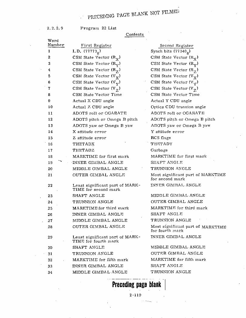
* PRECEDING PAGE BLANK NOT FILMEDProgram 22 List
Contens
,,or _First RegisterI.D. (777738)CSM State Vector (Rx)CSM State Vector (Ry)CSM State Vector (RzYCSM State Vector (R x)CSM State Vector (VY) CCSM State Vector (Vx)CSM State Vector (Vz)
CCSM State 'Vector Time CActual X CDU angle AActual Z CDU angle OADOTS roll or OGARATE
AD OTS pitch or Omega B pitch AlADOTS yaw or Omega B yaw AlX attitude error AZ attitude error RCTHETADX RCTHETADZ
TGaMARKTIME for first mark GalINNER GIMBAL ANGLE SIAMIDDLE GIMBAL ANGLE TRtOUTER GIMBAL ANGLE MosMos
Least significant part of MARK- INNfTIME for second markSHAFT ANGLETRUNNION ANGLE
MIDIOUT:MARKTIME for third mark MAR]INNER GIMBAL ANGLEMIDDLE GIMBAL ANGLE TUAFOUTER GIMBAL ANGLE Mostfor folLeast significant part of MARK- ITIME for fourth mark
SHAFT ANGLETRUNNION ANGLE
UTIDDMARKTIME for fifth mark MARKIINNER GIMBAL ANGLE SHAFT
MIDDLE GIMBAL ANGLE TRUNN
Preceding page blank 72-119
Second Register
Synch bits (773408)CSM State Vector (Rx)CSM State Vector (Ry)CSM State Vector (Rz)CSM State Vector (Vx)USM State Vector (Vy)CSM State Vector (Vz)2SM State Vector Timetctual Y CDU angle)ptics CDU trunnion angleDOTS roll or OGARATEDOTS pitch or Omega B pitchDOTS yaw or Omega B yawattitude error:S flags
IETADY
rbage
LRKTIME for first markIFT ANGLE
UNNION ANGLEst significant part of MARKTIMEsecond markER GIMBAL ANGLE
DLE GIMBAL ANGLEER GIMBAL ANGLEFKTIME for third mark'T ANGLE
TNION ANGLE
Significant part of MARKTIMEurth markR GIMBAL ANGLE
LE GIMBAL ANGLER GIMBAL ANGLETIME for fifth markANGLE
lION ANGLE
2. 2. 2. 9
WorNun
1
2
3
4
5
6
7
8
9
10
11
12
13
14
15
16
17
18
19
20
21
22
23
24
25
26
27
28
29
30
31
32
33
34
rdnhe r

Contents
First Register
OUTER GIMBAL ANGLE
LANDMARKSpare
Spare
Spare
Flagword 0
Flagword 2
Flagword 4
Flagword 6
Flagword 8
DSPTAB+0
DSPTAB+2
DSPTAB+4
DSPTAB+6
DSPTAB+8D
DSPTAB+1OD
TIME 2
LANDMARK LATITUDE
LANDMARK LONGiTUDE
LANDMARK ALTITUIDE
Spare
Spare
Spare
Spare
Actual X CDU angle
Actual Z CDU angle
ADOTS roll or OGARATE
ADOTS pitch or Omega B pitch
ADOTS yaw or Omega B yaw
OPTION1
TET
THETADX
THETADZ
* RSBBQ
Garbage
* C31FLWRD
* FAILREG+1
Optics Shaft
Second Register
Garbage
GarbageSpare
Spare
Spare
Flagword 1
Flagword 3
Flagword 5
Flagword 7
Flagword 9
DSPTAB+1
DSPTAB+3
DSPTAB+5
DSPTAB+7
DSPTAB+9D
DSPTAB+11D
TIME 1'
LANDMARK LATITUDE
LANDMARK LO N GI TU DE
LANDMARK ALTITUDE
Spare
Spare
Spare
Spare
Actual Y CDU angle
Optics CDU trunnion angle
ADOTS roll or OGARATE
ADOTS pitch or Omega B pitch
ADOTS yaw or Omega B yaw
OP TION2
TET
THETADY
Garbage
RSBBQ+1
Channel 77
FAILREG
FAILREG+2
PIPAX
* Indicates two single precision quantities that are not indicated otherwise.
2-120
WordNumber
35
36
37
38
39
40
41
42
43
44
45
46
47
48
49
50
51
52
53
54
55
56
57
58
59
60
61
62
63
64
65
66
67
68
69
70
71
72

Contents
First Register
PIPAY
Number of MarksFlagword 10
Landing Site Vector X comp.
Landing Site Vector Y comp.
Landing Site Vector Z comp.
Spare
OPTMODES
LM MASS
DAPDATR 1
ERROR X
ERROR Z
WBODY (roll) or OMEGAC (roll)
WBODY (pitch) or OMEGAC (pitch)
WBODY (yaw) or OMEGAC (yaw)
REDO COUNTER
Desired FINAL CDU Y
IMODES 30
Channel 11
Channel 13
Channel 30
Channel 32
Spare
Spare
Spare
Spare
Spare
Spare
Second Register
PIPAZ
Garbage
Flagword 11
Landing Site
Landing Site
Landing Site
Spare
HOLDFLAG
CM MASS
DAPDATR2
ERROR Y
Garbage
WBODY (roll
WBODY (pitc
WBODY (yaw
Desired FINI
Desired FINI
IMODES 33
Channel 12
Channel 14
Channel 31
Channel 33
Spare
Spare
Spare
Spare
Spare
Spare
Vector X comp.
Vector Y comp.
Vector Z comp.
0
1) or OMEGAC (roll)
ch) or OMEGAC (pitch)
v) or OMEGAC (yaw)
AAL CDU X
AL CDU Z
2-121
WordNumber
73
74
75
76
77
78
79
80
81
82
83
84
85
86
87
88
89
90
91
92
93
94
95
96
97
98
99
100

PRECEDING PAGE BLIANK NOT FILMED
2.2.2. 10 Program 22 List
Word Number Contents
la I. D. word for this list, 777738.
lb Synch bits, 773408.
2-17 Same as words 2-17 on the Powered List.
18-35a LANDING SITE MARK DATA. These thirty-five registers con-
tain the mark data which is being used to update the CSM state
vector in P22 and the landmark position coordinates in P22 and P24.
Each mark, of which five in P22 and an unlimited number in P24 are
allowed, consists of six parameters stored in seven registers. These
.qfantities, listed in the correct transmitted order, are:
Time since epoch (double precision) scaled centiseconds/22 8 .
Inner gimbal angle (CDUY)15-bit unsigned fractions,scaled degrees/360.
Middle gimbal angle (CDUZ)
Optics Trunnion angle, scaled (degrees-19. 7754)/45 (two'scomplement). The bias, 19. 7754, is programmed-in.
Outer gimbal angle (CDUX). A 15-bit unsigned fraction,
scaled degrees/360.
SVMRKDAT through SVMRKDAT +34 are set to zero upon entry
to P24. They are set with mark data immediately after each
individual mark in P22 and P24.'
P22MKFLG (bit 11 flagword 3)
is cleared upon entry to P22, P24. It is set to 1 in P22 after all
marks have been taken and in P24 after every individual mark to
signify that SVMRKDAT (words 18-35a) contains the latest mark
information. If CMOONFLG bit 12, flagword 8, is a zero, the
coordinate system is earth centered. A one in this bit position
would indicate a moon-centered coordinate system. In P24, if
more than five marks are taken, they are stored in a cyclic
manner, i. e., the sixth mark is stored in SVMRKDAT through
SVMRKDAT +6, the seventh mark is stored in SVMRKDAT +7
through SVMRKDAT +13, etc. A "mark reject" in P22 and P24
will cause the time registers of the latest mark to be comple-
mented. In P22, the next mark after a rejected mark is written
over the rejected mark while in P24 the next location is used.
Preceding page blank2-123

Word Number
35b
36a
36b
37-39
40-51
52
Contents
Garbage.
LANDMARK ID contains the R2 entry by the astronaut after a
V05N70 or V05N71 action. It contains five octal digits, ABCDE,
which describe the landmark as follows:
A = 1 if landmark is known.
A = 2 if landmark is unknown.
B = index of offset designator.
C = not used.
DE = 00 for a landmark whose coordinates are not stored
in the CMC memory.
= 01 for the landing site.
The offset indicator, B, is set to zero at the start of P22. Theastronaut may change all items after a V05N70 or V05N71. It is
used by P22 after each of these displays to extract the information
described above. P24 does not touch LANDMARK ID.
Garbage.
SPARES. The first half of each spare contains 000008. The secondhalf is ARTTPT (the. contents of the accumulator when the telemetry
interrupt was recognized).
Same as words 40 - 51 on the Powered List.
LANDMARK LATITUDE is the latitude of the landmark which P22 isupdating, scaled degrees/360. It may be either earth-centered or
moon-centered. If, upon entry of P22, CMOOTNFLG (Flagword 8,
bit 12) equals zero, the coordinate system is earth-centered. Con-
versely, the coordinate system will be moon-centered if CMOONFLG
equals one. It does not change within P22. The landmark may be
either known or unknown. If known, it may be either entered by the
astronaut, or obtained from the item, RLS (lunar landing site). The
range of values is -. 25 revolutions • LAT <. 25 revolutions. The
latitude is computed for known landmarks only at the start of P22.
At the completion of P22, the latitude is computed for all landmarks
and contains the updated value. Item LANDLAT occupies the same
locations as LAT and is identical in meaning. LANDLAT is the item
used by noun 89 to display landmark latitude. The foregoing descrip-
tion applies to P24 with the exception that the landmark must be
known and LANDMARK LATITUDE is only obtained from astronaut
input. Also, it changes whenever a mark is used to compute new
landmark coordinates.
2-124

Word Numb(
53
54
55-58
59-63
64, 65
66-73
74a
er Contents
LANDMARK LONGITUDE is the longitude of the landmark whichP22 is updating, scaled degrees/360. The range of values is
-. 5 revolutions < LONG < . 5 revolutions. It may be either 0
earth-centered or moon-centered. If, upon entry of P22,
CMOONFLG (Flagword 8, bit 12) equals zero, the coordinate system isearth-centered. Conversely, the coordinate system will be moon-centered if CMOONFLG equals one. The longitude is computed forknown landmarks only at the start of P22. At the completion of P22, thelongitude is computed for all landmarks and contains the updated value.
The foregoing description applies to P24 with the exception that the
landmark must be known and LANDMARK LONGITUDE is only ob-tained from astronaut input. Also, it changes whenever a mark is
used to compute new landmark coordinates.
LANDMARK ALTITUDE is the altitude of the landmark above theFischer Ellipsoid for earth orbit and above the mean lunar radius
for moon orbit, scaled meters/229. Tested values have variedbetween +2000 to -2000 meters. It may be either earth-centeredor moon-centered. If, upon entry of P22, CMOONFLG (Flagword 8,bit 12) equals zero, the coordinate system is earth-centered. Con-versely, the coordinate system will be moon-centered if CMOONFLGi quals one. The altitude is co.mputed for known landmarks only at
the start of P22. At the completion of P22, the altitude is com-puted for all landmarks and contains the updated value. The fore-
going description applies to P24 with the exception that the land-mark must be known and LANDMARK ALTITUDE is only obtainedfrom astronaut input. Also, it changes whenever a mark is usedto compute new landmark coordinates.
SPARES. Same description as word 37 of this list.Same as words 59-63 on the Powered List.
Same as words 64, 65 on the Coast and Align List.
Same as words 66-73 on the Powered List.
The number of valid Landing site marks, from one to five in P22
and any number in P24, which are stored in the SVIVMRDAT table,-14scaled 2 1 This item is computed by R53 and left in 8NN.
In P22 and P24, this quantity is initialized to 0 and incremented
by one immediately after every mark. In P24, if a mark is re-jected, the counter will not be decremented, while in P22, it
will be decremented.
2-125
ID

Word Number Contents
74b Garbage.
75 Same as word 77 of the Powered List.
76-78 LUNAR LANDING SITE POSITION VECTOR (X, Y, Z) measured
in moon-fixed coordinates from the center of the moon to the
surface of the moon at the landing site, scaled meters/27. It isused in lunar orbits only and must be selected by the astronaut
using nouns 70 or 71. If selected by the astronaut, it is used at the
start of P22 to compute the initial landmark vector (RL) and thenupdated at the end of P22 as a result of data computed from the re-
sults of astronaut-acquired sighting marks.
79 SPARE. Same description as word 37 of this list.
80-94 Same as words 80-94 of the Powered List.
95-100 SPARES. Same description as word 37 of this list.
2 -126

POWERED LIST - Mnemonics
WordNumber
la Identification
(777748)
lb Sync bits
(773408)
2-4 RN
5-7 VN
8 PIPTIME
9a CDUX
9b CDUY
10a CDUZ
10b CDUT
11-13 ADOT
14a AK
14b AK1
15a AK2
15b RCSFLAGS
16a HnE ADX
16b THETADY
17a THETADZ
17b garbage
18 TIG
19 DELLT4
20-22 RTARG
23 TGO
24 PIPTIME1
25-27 DELV
28a PACTOFF
28b YACTOFF
29a PCMD
29b YCMD
30a CSTEER
WordNumber
30b
31-33
34-39
40-44
45-50
51a
51b
52 -54
55-57
58
59a
'59b
60a
60b
61-63
64a
64b65a
65b
66a
66b
67a
67b
68
t6qa
69b
70a
70b-71b
72a
72b
73a
73b
74
garbage
DELVEET1
REFSMMA T
STATE
DSPTAB
TIME2
TIME1
R -OTHE R
V-OTHER
T -OTHER
CDUX
CDUY
CDUZ
CDUT
ADOT
AK
AKi
AK2
RCSFLAGS
THETADX
THETADY
THETADZ
garbage
RSBBQ
garbage
CHAN77
C31FLWRD
FAILREG
CDUS
PIPAX
PIPA Y
PIPAZ
ELEV
WordNumber
75
76
77
78
79a
79b
80a
80b
81a
81b
82a
82b
83a
83b
84a
84b
85-87
88a
88b-89b
90a
90b
91a
91b
92a
92b
93a
93b
94a
94b
95-97
98- 100
CENTANG
SPARE
STATE +10D
TEVENT
PCMD
YCMD
OPTMODES
HOLDFLAG
LEMMASS
CSMMASS
DAPDATR1
DAPDATR2
ERRORX
ERPRORY
ERRORZ
garbage
WBODY
REDOCTR
THETAD
IMODES30
IMODES33
CHAN11
CHAN 12
CHAN13
CHAN14
CHAN30
CHAN31
CHAN32
CHAN33
VGTIG
DELVEET2
2-127

COAST and ALIGN LIST -- Mnemonics
WordNumber
la Identification
(777778)
lb Sync bits
(773408)
2-4 RN
5-7 VN
8 PIPTIME
9a CDUX
9b CDUY
10a CDUZ
10b CDUT
11-13 ADOT
14a AK
14b AK1
15a AK2
15b RCSFLAGS
16a THETADX
16b THETADY
17a THETADZ
17b
18
19a
19b
20-23a
23b
24-27a
27b
28
29
30a
30b
garbage
TIG
BESTI
BESTJ
MA RKDOWN
garbage
MARK2DWN
garbage
HAPOX
HPERX
PACTOFF
YACTOFF
WordNumber
31-33
34 -39
40 -44
45-50
51a
51b
52 -54
55-57
58
59a
59b
60a
60b
61-63
64a
64b
65
66a
66b
67a
67b
68
69a
69b
70a
70b-71b
72a
72b
73a
73b
VGTIG
REFSMMAT
STATE
DSPTAB
TIME2
TIME1
R-OTHER
V-OTHER
T -OTHER.
CDUX
CDUY
CDUZ
CDUT
A DOT
OPT ION 1
OPTION2
TET
THETA DX
THETADY
THETADZ
garbage
RSBBQ
garbage
CHAN77
C31FLWRD
FAIL REG
CDUS
PIPAX
PIPAY
PIPAZ
WordNumber
74
75
76
77
78
79
80a
80b
81a
81b
82a
82b
83a
83b
84a
84b
85-87
88a
88b-89b
90a
90b
91a
91b
92a
92b
93a
93b
94a
94b
95- 100
OGC
IGC
MGC
STATE +-1OD
TEVENT
LAUN CHAZ
OPTMODES
HOLDFLAG
LEMMASS
CSMMASS
DAPDATR1
DAPDAT R2
ERRO RX
ERRORY
ERRORZ
garbage
WBODY
REDOCTR
THETAD
IMODES30
IMODES33
CHAN11
CHAN12
CHAN13
CHAN14
CHAN30
CHAN31
CHAN32
CIIAN33
DSPTAB
2 -1928

RENDEZVOUS and PRETHRUST LIST - Mnemonics
WordNumber
la Identification
(777758)
lb Sync bits
(773408)
2-4 RN
5-7 VN
8 PIPTIME
9a CDUX
9b CDUY
10a CDUZ
10b CDUT
11-13 ADOT
14a AK
14b AK1
15a AK2
1. b . .RCSFLAGS
16a THETADX
16b THETADY
17a THETADZ
17b garbage
18 TIG
19 DELLT4
20-22 RTARG
23 VHFTIME
24-27a MA RKDOWN
27b RM
28a VtHFCNT
28b TRKMKCNT
29 TTPI
30a ECSTEER
30b garbage
31 DEL VT PF
32 TCDH
WordNumber
33
34
35-37
38
39
40-44
45-50
51a
51b
52 -54
-55 -57
58
59a
59b
60a
60b
61-63
64a
64b
65
66a
66b
67a
67b
68
69a
69b
70a
70b-71b
72a
72b
73a
73b
74
TCSI
TPASS4
DEL VSL V
RANGE
RRATE
STATE
DSPTAB
TIME2
TIME 1
R-OTHER
V-OTHER
T-OTHER
CDUX
CDUY
CDUZ
CDUT
ADOT
OPTION1
OPTION2
TET
THETADX
THETADY
THETADZ
garbage
RSBBQ
garbage
CHAN77
C31FLWRD
FAILREG
CDUS
PIPAX
PIPAY
PIPAZ
DIFFALT
WordNumber
75
76
77-79
80a
80b
81a
81b
82a
82b
83a
83b
84a
84b
85-87
88a
88b-89b
90a
90b
91a
91b
92a
92b
93a
93b
94a
94b
95
96
97
98
99
100
CENTANG
SPARE
DEL VEET3
OPTMODES
HOLDFLAG
LEMMASS
CSMMASS
DAPDATR1
DAPDATR2
ERRORX
ERRORY
ERRORZ
garbage
WBODY
REDOCTR
THETAD
IMODES30
IMODES33
CEHAN 11
CHAN 12
CHAN 13
CHAN 14
CHAN30
CHAN31
CHAN32
CHAN33
RTHETA
LAT(SPL)
LNG(SPL)
VP RED
GAMMAEI
STATE +10D
2-129

ENTRY and UPDATE LIST - Mnemonics
WordNumber
la - Identification
(777768)
lb Sync bits
(773408)
2-4 RN
5-7 VN
8 PIPTIME
9a CDUX
9b CDUY
10a CDUZ
10b CDUT
11-13 ADOT
14a AK
14b AK1
15a AK2
1,bS RCSFLA G
16a THETAI)X
16b THETADY
17a THETADZ
17b
18a
18b
19a
19b
20
21-30
31a
31b
32a
32b
33a
garbage
CMDAPMOD
PREL
QREL
RREL
L/D1UPBUFF
COMPNUMB
UPOLDMOD
UPVERB
UPCOUNT
PAXERR1
WordNumber
33b
34
35
36
37
38
39a
39b
40-44
45 -50
51a
51b
52
53 -55
56
57
58
59a
59b
60a
60b
61-63
64a
64b
65
66a
66b
67a
67b
68a
ROLLTM
LATANG
RDOT
THETAH
LAT (SPL)
LNG(SPL)
ALFA/180
BETA/ 180
STATE
DSPTAB
TIME2
TIME].
PIPTIME1
DELV
TTE
VIO
VP RED
CDUX
CDUY
CDUZ
CDUT
ADOT
OPTION 1
OPTION2
TET
ERRORX
E RRO RY
E RRO RZ
THETADX
THETADY
WordNumber
68b THETADZ
69a CMDAPMOD
69b PREL
70a Q REL
70b RREL
71-80 UPBUFF
81a LEMMASS
81b CSMMASS
82a DAPDATR1
82b DAPDATR2
83a ROLLTM
83b ROLLC
84a OPTMODES
84b HOLDFLAG
85-87 WBODY
88,a REDOCT R
88b-89b THETAD
90a IMODES30
90b IMODES33
91a CHANll
91b CHAN12
92a CHAN13
92b CHAN14
93a CHAN30
93b CHAN31
94a CHAN32
94b CHI-AN33
95 RSBBQ
96a garbage
96b CHAN77
97a C31FLWRD
97b-98b FAILREG
99 STATE +10D
100 GAMMAEI
2-130

PROGRAM 22 LIST - Mhemonics
WordNumber
la Identification
(777738)
lb Sync bits
(773408)2-4 RN
5-7 VN
8 PIPTIME
9a CDUX
9b CDUY
10a CDUZ
10b CDUT
11-13 ADOT
14a AK
14b AK1
15a AK2
15b -- RCSFLAGS
16a THETADX
16b THETADY
17a THETADZ
17b
18-35a
35b
36a
36b
37-39
40-44
45-50
garbage
S VMRKDAT
garbage
LANDMARK
garbage
SPARE
STATE
DSPTAB
WordNumber
51a
51b
52
53
54
55-58
59a
59b
60a
60b
'61-63
64a
64b
65
66a
66b
67a
67b
68
69a
69b
70a
70b-71b
7 2a
72b
73a
73b
74a
TIME2
TIME1
LAT
LONG
ALT
SPARE
CDUX
CDUY
CDUZ
CDUT
ADOT
OPTION1
OPTION2
TET
THETADX
THETADY
THETADZ
garbage
RSBBQ
garbage
CHAN77
C31FLWRD
FAIL REG
CDUS
PIPAX
PIPAY
PIPAZ
8NN
WordNumber
74b garbage
75 STATE +10D
76-78 RLS
79 SPA RE
80a OPTMODES
80b HOLDFLAG
81a LEMMASS
81b CSMMASS
82a DAPDATR1
82b DAPDATR2
83a ERRORX
83b ERRORY
84a ERRORZ
84b garbage
85-87 WBODY
88a. REDOCTR
88b-89b THETAD
90a IMODES30
90b IMODES33
91a CHAN11
91b CHAN12
92 a CHAN13
92b CHAN14
93a CHAN30
93b CHAN31
94a . CHAN32
94b CHAN33
95-100 SPARE
2-131

PR.ECDING PAGE BLANK NOT FALMED
ALPHABETICAL LISTING OFFLAG BITS AND LOCATIONS
The following table is taken directly from the current program listing.
FLAGWORD BIT AND FLAG
OC5GSW22DSPFLG36CSW.3-S XISF LGADVTP.KAMOCNFLGAPSESWASTNFLAGATTCHFLGAUTGSEaAVEGFLAGAVEMIDSWAVFL AGAZIMFLAGBURNFLAGrAL-C-MAN42CMDAPARMCMOONFLGCM/DSTBYCOGAFLAGCOMPUTERCSI_-SLAG --CUL TFLAGCYC6iFLGCt0OR9FLGDAPBIT1OAP IT72DIMOFLAGDMENFLGDRIFTFLGDSKYFLAGEGSWENG2FLAGENGONFLGENTRYDSPERADELAG_ETPTFLAGFZRTEFINALFLGFIRSTFLGFREEFLAG_EUL_TKYELG_
GAMDIFSWGLOKFAILGONEBYGONEPASTGPRBKFLG
GYMDIFSW.HAFLAG_
BIT 3 FLAG 6BIT 13 FLAG 2BIT' 1 FLAG 8B I TL-6FG_5-BIT 1, FLAG 8BIT 2 FLAG t;BIT 5 FLAG eBIT 12 FLAG 7BIT -2 FLAG 7BIT. 7 -FLAAG LBIT I FLAG 1BIT 1 FLAG 9BIT 5 FLAG 2BIT 8 FLAG 11BIT IC FLAG 10BLLT 2_ELAGZBIT 12 FLAG 6BIT 12 FLAG aBIT 2 FLAG 6BIT 4 FLAG 8BIT 8 FLAG 5.QI T-- : FJAG 11-IBIT 7 FLAG 3BIT 4z FLAG CBIT 2 FLAG 3BIT 15 FLAG 6BIT 14 FLAG 6BIT 1 FLAG 3BIT 9 FLAG 5BIT 15 FLAG_. 2__BIT 15 FLAG 5BIT 8 FLAG 6BIT 11 FLAG 1BIT 7 FLAG 5BIT 13 FLAG 6BIrT 13 ._FLA 1. _BIT 7 FLAG 2BIT 5 FLAGQ _BIT 6 FLAG 2BIT 7 FLAG 2BIT 3 FLAG 0
_BIL2_ FLAJ 1CBIT 11 FLAG 6BIT 1Q..FLAG ._BIT 8 FLAG 7BIT 10 FLAG. 6BIT 5 FLAG 5BIR 2 FlAG__1BIT 1 FLAG 6BIT ..ELAG_11__
Preceding page blank
FLAGWORD
HDSUPFLGHINDI DL EFA IL.IGNFLAGIMPULSWIMUSEINCORFLGINF INFLGINRLSWINTFLAGINTYPFLGITSWICHJSWITCHKNflWNFLGLATSWLMOONFLGLUNAFLAGMANEUFLGMARKFLGMAXDBFLG
MIDiFLAGMIDAVFLGMIDFLAGMKOVFLAGMOONFLAGMRKIDFLGMRKNVFLGMEIRUPTFLGM.I T F LGN22DRN 17NEEDLFLGNEWIFLG
.NEWLMFLGNEWTFLAG
__NJETSF LG_NODOFLAGNODOPO1NrRFHORNORMSWNOSWITCH
-- NUP 1DF LNRMNVFLGNRUPTFLGNWAITFLGORBWFLAGORDERSW
-P2-1L EAG-P22MKFLGP24FLAGPZ24MKFLGP29FLAG
'
BIT AND FLAG
BITBITEBITBITBITBITRITBITBITBITBIT
B I T
BITBIT
B ITBIT
BITBITBITBIT
BIT
BITBITBITBIT
B I T
BITB!T
BITB I TBITBIT
B I T
BIT
BITBITBITB I TBITBITBITU I TBITBITBITBIT
BIT-BIT
BIT
B ITBITBIT
11 FLAG 10. FLAG 66 FLAG 113 -ILAG_ 7.._q FLAG 29 FLAG O11 FLAG 57 FLAG es' FLAG 614 FLAG. 1-4 FLAG 314 FLAG 714 FLAG 33 FLAG 64 FLAG 6.11 FLAG B12 FLAG 35 FLAG 1('4 FLAG 112 FLAG 9
3 FLAG 92 FLAG 913 FLAG C'3 FLAG 412 FLAG 315 FLAG 49 FLAG 45 FLAG 411. FLAG .._..6 FLAG 99 FLAG -13 FLAG 814 FLAG 819 FLAG 5_L5 £.LAG '-11 FLAG 212 FLAG 111 FLAG 01D FLAG 77 FLAG 613-.FILAGA 4.-.8 FLAG 44 FLAG 410 FLAG 46 FLAG 36 FLAG 812- FLAG 2---11 FLAG 314 FLAG 9
3 FLAG 21 FLAG 0
2-133
G0e,

ALPHABETICAL LISTING OFFLAG BITS AND LOCATIONS
(cont.)
FLAGWORD BIT AND FLAG FLAGWORD BIT AND FLAG
BIT 8 FLAG 10BIT--I- FLAG --ILBIT 15 FLAG 10BIT--1- FLAGJ.------4BIT 4 FLAG 2B-T.-6- FLAG ..-------BIT q FLAG 3BIT R Fl.AG 3BIT 14 FLAG 4BIT 7_ELAG 4_ _BIT 4 FLAG 10B LT5 FLAG_.9 ..BIT 14 FLAG 2
_BLT 7 FLAr 9BIT 4 FLAG 9BIT 6 FLAG C._...BIT 2 FLAG 8BIT .9 FLAG 10 BIT 13 FLAG 3
_BIT 13 FLAG 10BIT 12 FLAG 10BIT 9 FLAG.6 ..BIT I FLAG 5-%3TT .14 FLAG 5BIT 7 FLAG O'BIT 15 FLAG 8 _BIT 9 FLAG 7-BIT 5--i FLAG !1-BIT 14 FLAG 11BIT 13 FLAG 11--BIT 12 FLAG 11BIT 10 FLAG 9 --BIT 10 FLAG 2RIT'3 FIAG 1 -
SLOWFLGSGLFISISOURCFLGSTATEFLGSTEERSh-SITIFLAGSTRULLSWSURFFLAGSWT.NVERTARG1FLGTARG2FLSGTLEA":IFLGTFFSWTIMRFLAGTPIMNFLGTRACKFLGUPDATFLGUPLnCKFL-UTFLAGV37FLAGV50N18FLV59FLAGV82EMFLGVgZF LAG___V960NFLGVEHUPFLGVER IFLAGVFLAG,VHFRFLAGYVIlNTFLAGVNFLAG.XDELVFLGXDSPFLAGZM EASURE
BIT 13 FLAG 5BIT 3 FLAG 5BIT 8 FLAG 9BIT 5 FLAG 3BIT 11 FLAG 2_Bl T_.14 ELAGi_BIT 13 FLAG 6BIT 8 FLAG 6BIT 15 FLAG 9BIT 13 FLAG 1BIT 0 FLAG 1
.BiI 15-.: F -AG 1 -BIT 1 FLAG 7BIT 11 FLAG 7BIT 3 FLAG 1GBIT 5 FLAG 1BIT 7 FLAG 1BI 4 _ELAG "BIT 9 FLAG 8BIT 6 FLAG 7BIT 15 FLAG 3BIT 12 FLAG 5BIT 13 FLAG qBIT- L F LAG IBIT 3 FLAG 8BIT 3 FLAG 1BIT 3 FLAG 7BIT 10 FLAG 3BIT q FLAG 9
._BlT_ 3_FLAG_-3'BIT 2 FLAG 4BIT B FLAG 2BIT 1 FLAG 4BIT 10 FLAG U
2-134
P35FLAGPCFLAGPCMANFLGPDSPFLAGPFRATFLGPINBRFLGPOOFLAGPRFrFI rGPRIODFLGPRONVFLGPTV93FLGQUITFLAGR21MARK
_R22CAFGG _.R31FLAGR53FLAGR67FL. AG.RANGFLAGREFSMFLGO TF!TlFLGREJCTFLGRELVELSWRENDWFLGRETROFLGRNDVZFLGRPQFLAGRVSWS32.1F S32 01F2S3201F3AS32.1F3BSAVECFLGSKI PVHFSL nDPFS.

EFFECTS OF FRESH START (V36) AND HARDWARE
RESTART ON FLAGWORDS AND CHANNEL BITS
APPEARING ON DOWNLISTS
Downlist Fresh Start (V36) Hardware RestartFlagword Word 15-13 12-10 987 654 321 15-13 12-10 987 654 321
0 40 000 000 000 000 000 UUU UUU UUU UU0 UUU
1 40 000 U00 000 000 000 UUU UUU UUU UCO UUU
2 41 000 000 000 000 000 COU OU1 UUU UUU UUU
3 41 00U 000 000 000 000 UUC UUU UUU UUU UUU
4 42 000 000 000 000 000 000 000 000 000 000
5 42. 000 000 010 000. 000 UUU UUU UUU UUU UUU
6 43 000 000 000 000 100 UUU UUU UUU UUU UUU
7 43 000 000 000 000 000 UUU UUU UUU UUU UUU
8 44 000 UU0 0U0 000 000 UUU UUU UUU UUU UUU
9 44 000 000 000 000 000 UUU UUU UUU UUU UUU
10 (varies) 000 0U0 000 000 000 UOU UUU UUU UUU UUU
11 (varies) 000 000 000 000 000 UUU UUU UUU UUU UUU
DownlistChannel Word Fresh Start (V36) Hardware Restart
11 91 000 000 000 000 000 00+ 000 000 000 OOU
12 91 000 000 000 :,0' 000 000 000 000 *0* 000
13 92 000 000 000 000 000 000 000 000 000 000
14 92 000 000 000 000 000 000 000 000 000 000
30 93 UUU UUU UUU UUU UUU UUU UUU UUU UUU UUU
31 93 UUU UUU UUU UUU UUU UUU UUU UUU UUU UUU
32 94 UUU UUU UUU UUU UUU UUU UUU UUU UUU .UUU
33 94 UUU UUU UUU UUU UUU 111 11U UUU UUU UUU
77 (varies) 000 000 000 000 000 RRR RRR RRR RRR RRR
KEY: 0 - Bit set to 01 - Bit set to 1U - Bit unchanged: - If IMU was in Coarse Align,
set bits 4 and 6, otherwisereset to 0
+ - Set to 1 if ENGONFLG is on,otherwise reset to 0
C -Bit set to 0 if IMU was inCoarse Align otherwiseunchanged.
R. - Set I if this bit indicates cause ofrestart, otherwise unchanged
2-135
o
I8
0
0
o
o

TLANK
2-136

COLOSSUS 3
R-577
Internal Distribution List
Group 23A D. Lutkevich
BrennanBrandHigginsLevineMuller
Group 23B C. Flynn
KlawsnikNayar
I DL7-211 (10)
PhillipsPuReberRobertsonTempelman
DL7-221L
Reed
( 3)
Group 23B
Group 23B
Group 23C
C. Taylor
BarnertB e al'sBrodeur (10)CramerGoodeHamiltonHaslam
J. Flaherty.
AlbertBerman Engel
M. Erickson
BairnsfatherBasile.CroopnickFraserJonesKalanMaybeck
DL7-221L
LollarMcCoyNevilleOstanekRyeWhittredgeZeldin
DL7-238A
MillardSchulenberg
DL7-215J
PenchukPotterSchlundtTurnbullWombleWork
Group 23D S. Beaulieu
DrakeDunbarGroomeJohnsonKiburz
DL7-213
LarsonMetzingerOlssonWalsh
D -1
(23)
(13)
( 9)

Group 23H R. Shane
CookKossuth
DL7-272 ( 3)
O' Connor
Group 23N G. Grover
BlanchardJohnson
DL11-201 ( 4)
OgletreeParr
Group 23P
Group 23P
Group 23S
E. Talbot
Greene
B. Hwoschinsky
Battin
P. Amsler
AdamsCanepaFellemanHeinemann
Group 23T J. Grinnel
EdmondsGraccKidoLones
DL7-148B ( 7)
MegnaSheridanSt. Amand
D. Farrell
Lawrence
J. Hargrove
DraneGlick
APOLLO Library
CSDL Technical Documrntation Center
D-2
DL7- 252
Stubbs
( 2)
DL7- 203
Copps
( 2)
DL7- 140
McOuat\Verner\WhiteWoosley
( 8)
Group 23
Group 33
DL7-283
DL7- 111
JohnsonMlimno
( 1)
( 4)
( 2)
( 2)

External Distribution List
COLOSSUS 3
Charles Stark Draper Laboratory (5)P.O. Box 21025Kennedy Space CenterAttn: Mr. R. O'Donnell
Charles Stark Draper Laboratory ( 3)Code EG/MIT Building 16NASA Manned Spacecraft CenterHouston, Texas 77058Attn: Mr. G. Silver
NASA MSC HW (10)Building M7-409Kennedy Space CenterFlorida 32815Attn: Mr. F. Hughes
Mr. A. Metzger (NASA/RO) ( 1)
Delco Electronics Division ( 2)Milwaikee, Wisconsin 53201Attn: Mr. J. Stridde, Dept. 42-02
Mr. W. Siarnicki, Dept; 94-02Building 2-C
Delco Electronics Division (2)P.O. Box 21027Kennedy Space CenterFlorida 32815Attn: Mr. J. Kaiser
Delco Electronics Division (1)P.O. Box 265Bethpage, Long IslandNew York 11714Attn: Mr. D. Dettmann
Delco Electronics'Division ( 1)P.O. Box 734 /Downey, California 90241Attn: Mr. D. KIarstedt
I(ollsman Instrument Corporation (1)575 Undlerhill BoulevardSyosset, Long IslandNew YorkAttn: Mr. I1. McCoy
D-3

( 6)Raytheon CompanyBoston Post RoadSudbury, Mass. 01776Attn: Mr. R. Zagrodnick
NASA/ MSFC National Aeronautics and Space AdministrationGeorge C. Marshall Space Flight CenterHuntsville, Alabama 35812
Attn: J. Mack R-ASTR-5V. Buckelew S&E-AERO-MFGA. Deaton R-AERO-DGF. Moore R-ASTR-NH. Hosenthien R-ASTR-FD. Germany I-I/IB-ER. Barraza I-V-EW. Chubb R-ASTR/NGJ. McCullough I-VE/T
NASA/MSC National Aeronautics and Space AdministrationManned Spacecraft CenterAPOLLO Document Control Group (BM86)Houston, Texas 77058Attn: Mr. J. Garman, FS6
(letter of transmittal only)
(180 + 1R)
LINIK Group, GPSI SIMCOM ( 3)1740 A NASA BoulevardHouston, Texas 77058Attn: Mr. D. Klingbell
NASA/GSFC
NASA/RASPONAR
NASA/ KSC
NASA/RtlASPOGE
National Aeronautics and Space Administration,Goddard Space Flight CenterGreenbelt, Maryland 20771Attn: Mr. P. Pashby, Code 813
National Aeronautics and Space AdministrationResident APOLLO Spacecraft Program OfficeNorth American Rockwell, Inc.Space and Information Systems DivisionCSM Data ManagementD/096- 704 AE9912214 Lakewood BoulevardDowney, California 90241
National Aeronautics and Space AdministrationKennedy Space CenterFlorida 32899Attn: Technical Document Control Office
General Electric CompanyAPOLLO SystemsP. O. Box 2500Daytona Beach, Florida 32015Attn: Mr. E. P. Padgett, Jr. /Unit 509
D-4
(10)
(1)(1)(1)(1)(1)(1)(1)(1)(1)
LINK
( 2)
(1 + 1R)
( 3)
( 1)

NASA/ HD C
NASA/ LE WIS
NASA/ FRC
NASA/LRC
NAR/KSC
GAC
NASA/ WSMR
NASA ceadquarters600 independence Avenue SWWashingtonl, D. C. 205416Attn:
Mission Director, Code MARobert Aller, Code MAO
( 2)-
(1)(1)
National Aeronautics and Space AdministrationLewis Research CenterCleveland, Ohio 44135Attn: Library
National Aeronautics and Space AdministrationFlight Research CenterEdwards AFB, California 93523Attn: Research Library
National Aeronautics and Space AdministrationLangley Research CenterLangley AFB, Virginia 23365Attn: Mr. A. T. Mattson
Kennedy Space CenterFlorida 32'815M. S. O. B.North American Mail{ Station ZK69Attn: Mr. D. Matteson
.Na+tional Aeronautics and' Spacc.Resident;APOLLO Spacecraft Program OfficerGrummanh Aerospace CorporationBethpage, Long IslandNew York 11714
National Aeronautics and Space AdministrationPost/Office Drawer MMLas'Cruces, New Mexico 88001Attn: RH4 Documentation
/L
D-5
( 2)
( 1)
( 2)
( 1)
( 2)
( 2)