Embed Size (px)
Citation preview
R-410AMODELS: YC090 Thru 300
YD120 Thru 240
7.5 - 25 Ton
60 Hertz
5184118-YIM-D-0118
TABLE OF CONTENTSNomenclature . . . . . . . . . . . . . . . . . . . . . . . . . . . . . . . . . . . . . 2General . . . . . . . . . . . . . . . . . . . . . . . . . . . . . . . . . . . . . . . . . . 2Renewal Parts . . . . . . . . . . . . . . . . . . . . . . . . . . . . . . . . . . . . . 3Agency Approvals . . . . . . . . . . . . . . . . . . . . . . . . . . . . . . . . . . 3Inspection . . . . . . . . . . . . . . . . . . . . . . . . . . . . . . . . . . . . . . . . 3
Physical Data . . . . . . . . . . . . . . . . . . . . . . . . . . . . . . . . . . . 4Installation . . . . . . . . . . . . . . . . . . . . . . . . . . . . . . . . . . . . . . . . 5
Preceding Installation . . . . . . . . . . . . . . . . . . . . . . . . . . . . . 5Limitations . . . . . . . . . . . . . . . . . . . . . . . . . . . . . . . . . . . . . . 5Location. . . . . . . . . . . . . . . . . . . . . . . . . . . . . . . . . . . . . . . . 5Clearances . . . . . . . . . . . . . . . . . . . . . . . . . . . . . . . . . . . . . 7Rigging . . . . . . . . . . . . . . . . . . . . . . . . . . . . . . . . . . . . . . . . 7
Phasing . . . . . . . . . . . . . . . . . . . . . . . . . . . . . . . . . . . . . . . . 8Electrical Data . . . . . . . . . . . . . . . . . . . . . . . . . . . . . . . . . . . 9Refrigerant Mains . . . . . . . . . . . . . . . . . . . . . . . . . . . . . . . 11Piping And Electrical Connections . . . . . . . . . . . . . . . . . . 21
Start-Up . . . . . . . . . . . . . . . . . . . . . . . . . . . . . . . . . . . . . . . . . 21Crankcase Heater . . . . . . . . . . . . . . . . . . . . . . . . . . . . . . . 21
Operation . . . . . . . . . . . . . . . . . . . . . . . . . . . . . . . . . . . . . . . 22Sequence of Operation . . . . . . . . . . . . . . . . . . . . . . . . . . . 22Cooling Sequence Of Operation . . . . . . . . . . . . . . . . . . . . 22
Control Board Navigation Components. . . . . . . . . . . . . . . . . 24Typical Wiring Diagrams . . . . . . . . . . . . . . . . . . . . . . . . . . 36
Start-Up Sheet . . . . . . . . . . . . . . . . . . . . . . . . . . . . . . . . . . . 43
LIST OF TABLES1 YC090 - 300 and YD120 - 240 Physical Data . . . . . . . . . 42 Unit Application Data . . . . . . . . . . . . . . . . . . . . . . . . . . . . 53 Corner Weights & Center of Gravity . . . . . . . . . . . . . . . . 64 Minimum Clearances . . . . . . . . . . . . . . . . . . . . . . . . . . . . 75 Electrical Data - Outdoor Unit - AC Without Powered
Convenience Outlet . . . . . . . . . . . . . . . . . . . . . . . . . . . . . 96 Electrical Data - Outdoor Unit - AC With Powered
Convenience Outlet . . . . . . . . . . . . . . . . . . . . . . . . . . . . 10
7 YC090, YC/YD120, YC/YD150 Unit Height Dimensions 198 YC/YD180, YC/YD240 and YC300 Unit Height
Dimensions . . . . . . . . . . . . . . . . . . . . . . . . . . . . . . . . . . 219 Piping And Electrical Connection Sizes . . . . . . . . . . . . . 21
10 Smart Equipment™ UCB Details . . . . . . . . . . . . . . . . . . 2511 Cable for FC Buses and SA Buses in Order of
Preference . . . . . . . . . . . . . . . . . . . . . . . . . . . . . . . . . . . 30
LIST OF FIGURES1 Corner Weights & Center Of Gravity . . . . . . . . . . . . . . . . 62 Typical Rigging . . . . . . . . . . . . . . . . . . . . . . . . . . . . . . . . 73 Typical Simplified Field Wiring Diagram – NC180 thru 240
Evaporator with YC150 thru 240 Condenser . . . . . . . . . 134 Typical NC120 - 240 Liquid Line Solenoid Wiring . . . . . 135 Typical Simplified Field Wiring Diagram - NC300
Evaporator Unit with YC300 Condenser Unit . . . . . . . . . 146 Typical NC300 Liquid Line Solenoid Wiring . . . . . . . . . . 147 Typical Simplified Field Wiring Diagram – ND180 thru 240
Evaporator with YD150 thru 240 Condenser . . . . . . . . . 158 Typical Simplified Field Wiring Diagram – NL090
Evaporator with YC090 Condenser . . . . . . . . . . . . . . . . 169 Typical Simplified Field Wiring Diagram – NL120 thru 240
Evaporator with YC120 thru 240 Condenser . . . . . . . . . 1710 Typical NL120 - 240 Liquid Line Solenoid Wiring . . . . . 1711 Typical Simplified Field Wiring Diagram – NM120 thru 240
Evaporator with YD120 thru 240 Condenser . . . . . . . . . 1812 YC090, YC/YD120, YC/YD150 Unit Dimensions . . . . . . 1913 YC/YD180, YC/YD240 & YC300 Unit Dimensions and
Piping & Electrical Dimensions . . . . . . . . . . . . . . . . . . . 20
14 Fan Orientation - Control Box End . . . . . . . . . . . . . . . . . 2415 Unit Control Board . . . . . . . . . . . . . . . . . . . . . . . . . . . . . 2416 YC090 Charging Chart. . . . . . . . . . . . . . . . . . . . . . . . . . 3117 YC120 Charging Chart. . . . . . . . . . . . . . . . . . . . . . . . . . 3118 YD120 Charging Chart. . . . . . . . . . . . . . . . . . . . . . . . . . 3219 YC150 Charging Chart. . . . . . . . . . . . . . . . . . . . . . . . . . 3220 YD150 Charging Chart. . . . . . . . . . . . . . . . . . . . . . . . . . 3321 YC180 Charging Chart. . . . . . . . . . . . . . . . . . . . . . . . . . 3322 YD180 Charging Chart. . . . . . . . . . . . . . . . . . . . . . . . . . 3423 YC240 Charging Chart. . . . . . . . . . . . . . . . . . . . . . . . . . 3424 YD240 Charging Chart. . . . . . . . . . . . . . . . . . . . . . . . . . 3525 YC300 Charging Chart. . . . . . . . . . . . . . . . . . . . . . . . . . 3526 Typical YC090 Condensing Unit Wiring Diagram . . . . . 3627 Typical YC120 - 150 Condensing Unit Wiring Diagram . 3728 Typical YD120 - 150 Condensing Unit Wiring Diagram . 3829 Typical YC180 Condensing Unit Wiring Diagram . . . . . 3930 Typical YC240 Wiring Diagram . . . . . . . . . . . . . . . . . . . 4031 Typical YC300 Wiring Diagram . . . . . . . . . . . . . . . . . . . 4132 Typical YD180 - 240 Wiring Diagram. . . . . . . . . . . . . . . 42
5184118-YIM-D-0118
2 Johnson Controls Ducted Systems
Nomenclature
General
These condensing units are designed for outdoor installation on a roof or at ground level. Every unit is completely piped and wired at the factory and is shipped ready for immediate installation. Only the liquid and suction lines to the evaporator coil, the filter drier, the thermostat wiring and the main power wiring are required to complete the installation. Each unit is dehydrated, evacuated, leak tested and pressure tested at 450 psig before being pressurized with a holding charge of refrigerant R-410A for shipment and/or storage.
All controls are located in the front of the unit and are readily accessible for maintenance, adjustment and service. All wiring (power and control) can be made through the front of the unit.
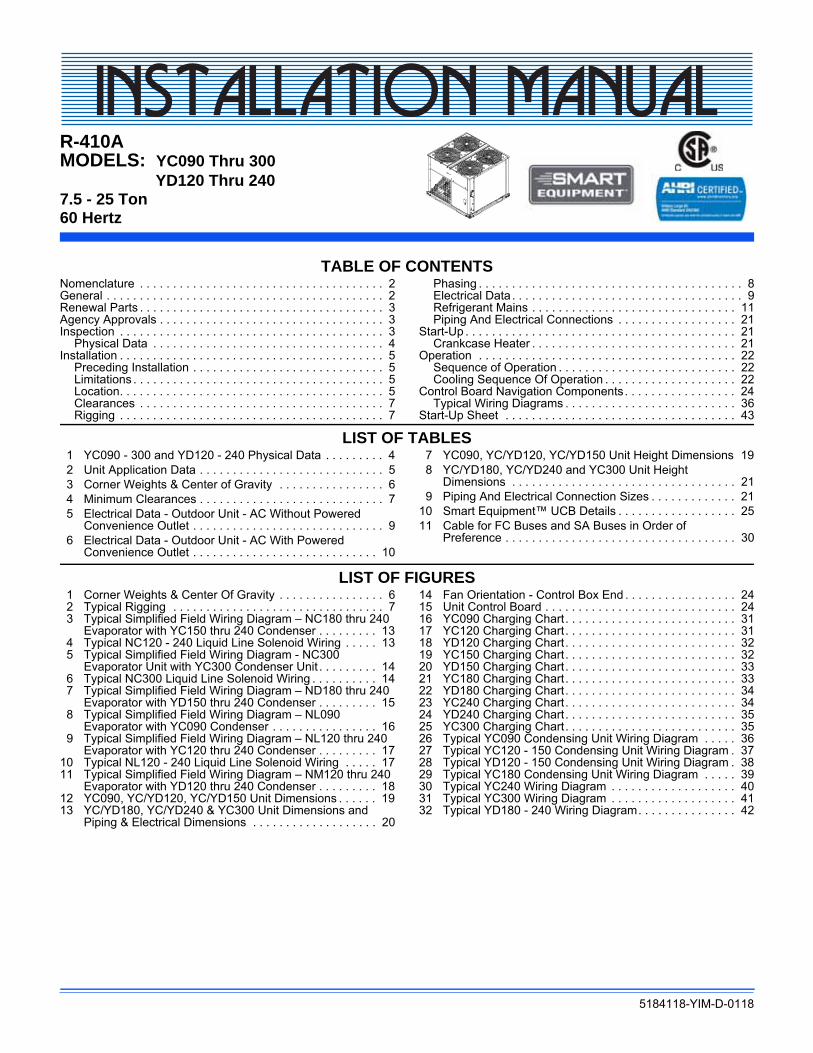
Product CategoryY = Split System, Condenser, AC, R-410A
Product IdentifierC = Standard Efficiency, 2-Pipe, R-410AD = Standard Efficiency, 4-Pipe, R-410A
Nominal Cooling Capacity - MBH090 = 7.5 Ton120 = 10 Ton150 = 12.5 Ton180 = 15 Ton240 = 20 Ton300 = 25 Ton
C00 = Cooling Only
Product OptionsAA = NoneAB = Phase MonitorAC = Coil GuardAE = Phase Monitor + Coil GuardEA = E-Coat Condenser CoilEB = E-Coat Condenser Coil + Phase MonitorEC = E-Coat Condenser Coil + Coil GuardEE = E-Coat Condenser Coil + Coil Guard + Phase MonitorLA = Low AmbientLB = Low Ambient + Phase MonitorLC = Low Ambient + Coil GuardLD = Low Ambient + Phase Monitor + Coil GuardLE = Low Ambient + Technicoat Cond. CoilLF = Low Ambient + Technicoat Cond. Coil + Phase MonitorLG = Low Ambient + Technicoat Cond. Coil + Coil GuardLH = Low Ambient + Technicoat Cond. Coil + Phase Monitor + Coil GuardLJ = Low Ambient + ElectroFin Cond. CoilLK = Low Ambient + ElectroFin Cond. Coil + Phase MonitorLL = Low Ambient + ElectroFin Cond. Coil + Coil GuardLM = Low Ambient + ElectroFin Cond. Coil + Phase Monitor + Coil GuardTA = Technicoat Condenser CoilTB = Technicoat Condenser Coil + Phase MonitorTC = Technicoat Condenser Coil + Coil GuardTE = Technicoat Condenser Coil + Coil Guard + Phase Monitor
Installation OptionsA = NoneB = Option 1C = Option 2D = Options 1 & 2E = Option 3G = Options 1 & 3H = Options 2 & 3J = Options 1, 2 & 3P = Options 3 & 5Q = Options 1, 3 & 5S = Option 5T = Options 1 & 5
2 = 208/230-3-604 = 460-3-605 = 575-3-60
Configured Split Condenser Model Number Nomenclature
A = Standard MotorAirflow
Product Generation5 = Fifth Generation
Voltage
Heat Type & Nominal Heat Capacity
Y C 300 C00 A 2 A AA 5 AProduct Style
A = Style A
1 = Disconnect2 = Non Pwr’d Conv Outlet3 = BACnet MS/TP on Smart Equipment™5 = Pwr’d Conv Outlet
Options
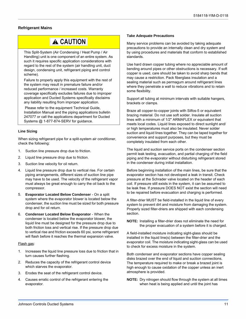
This Split-System (Air Condensing / Heat Pump / Air Handling) unit is one component of an entire system. As such it requires specific application considerations with regard to the rest of the system (air handling unit, duct design, condensing unit, refrigerant piping and control scheme).
Failure to properly apply this equipment with the rest of the system may result in premature failure and/or reduced performance / increased costs. Warranty coverage specifically excludes failures due to improper application and Ducted Systems specifically disclaims any liability resulting from improper application.
Please refer to the equipment Technical Guide, Installation Manual and the piping applications bulletin 247077 or call the applications department for Ducted Systems @ 1-877-874-SERV for guidance.
5184118-YIM-D-0118
Johnson Controls Ducted Systems 3
Safety Considerations
Installer should pay particular attention to the words: NOTE, CAUTION, and WARNING. Notes are intended to clarify or make the installation easier. Cautions are given to prevent equipment damage. Warnings are given to alert installer that personal injury and/or equipment damage may result if installation procedure is not handled properly.
Reference
This instruction covers the installation and operation of the basic condensing unit. For refrigerant piping installation instructions refer to document 247077 “Application Data - General Piping Recommendations for Split System Air Conditioning and Heat Pumps”. For information on the installation and operation of the evaporator blower units, refer to the Installation Manual that comes with the unit.
All accessories come with a separate Installation Manual.
Renewal Parts
Contact your local Source 1 Distribution Center for authorized replacement parts.
Agency Approvals
Design certified by CSA as follows:
1. For use as a cooling unit.
2. For outdoor installation only.
Inspection
As soon as a unit is received, it should be inspected for possible damage during transit. If damage is evident, the extent of the damage should be noted on the carrier’s freight bill. A separate request for inspection by the carrier’s agent should be made in writing.
Improper installation may create a condition where the operation of the product could cause personal injury or property damage. Improper installation, adjustment, alteration, service or maintenance can cause injury or property damage. Refer to this manual for assistance or for additional information, consult a qualified contractor, installer or service agency.
Before performing service or maintenance operations on unit, turn off main power switch to unit. Electrical shock could cause personal injury. Improper installation, adjustment, alteration, service or maintenance can cause injury or property damage. Refer to this manual. For assistance or additional information consult a qualified installer, service agency or the gas supplier.
This system uses R-410A Refrigerant which operates at higher pressures than R-22. No other refrigerant may be used in this system. Gage sets, hoses, refrigerant containers and recovery systems must be designed to handle R-410A. If you are unsure, consult the equipment manufacturer. Failure to use R-410A compatible servicing equipment may result in property damage or injury.
This product must be installed in strict compliance with the enclosed installation instructions and any applicable local, state and national codes including, but not limited to, building, electrical, and mechanical codes.
5184118-YIM-D-0118
4 Johnson Controls Ducted Systems
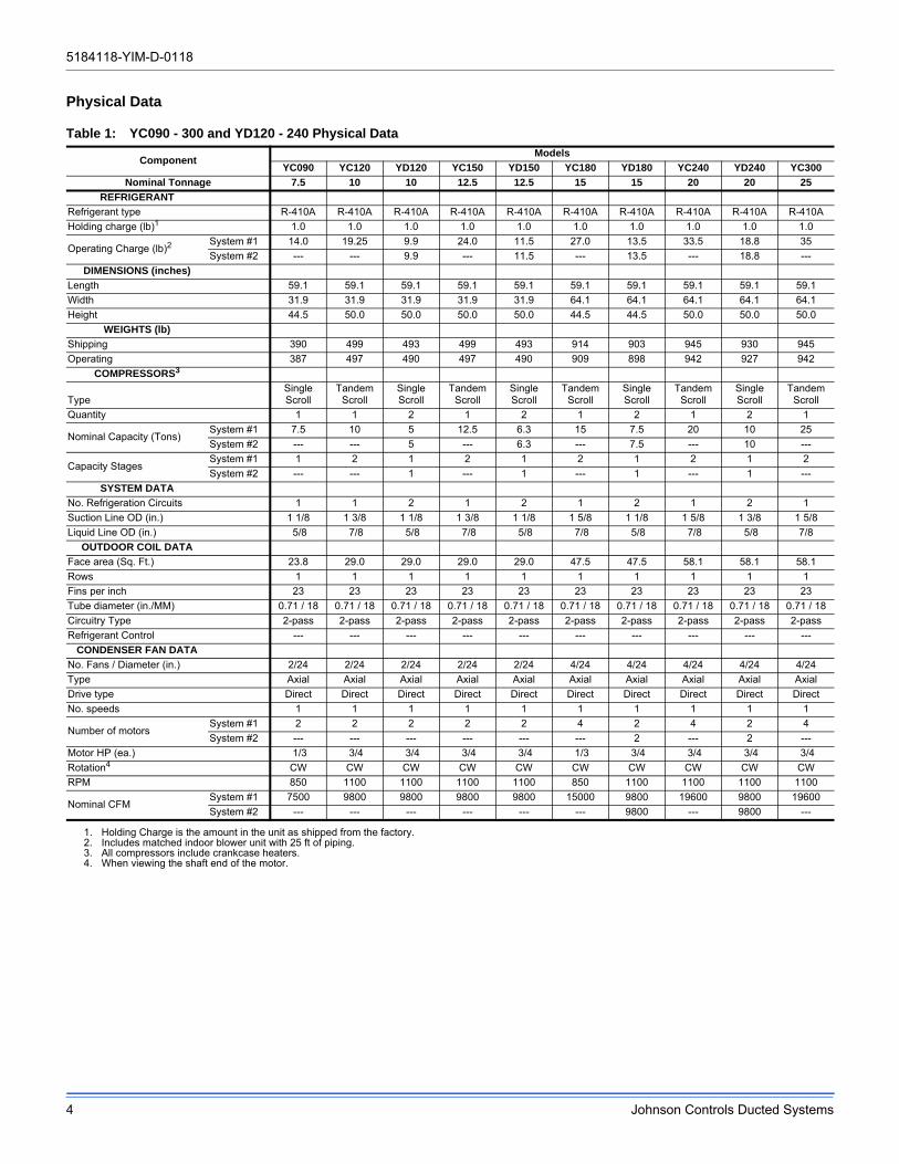
Physical Data
Table 1: YC090 - 300 and YD120 - 240 Physical Data
ComponentModels
YC090 YC120 YD120 YC150 YD150 YC180 YD180 YC240 YD240 YC300
Nominal Tonnage 7.5 10 10 12.5 12.5 15 15 20 20 25
REFRIGERANT
Refrigerant type R-410A R-410A R-410A R-410A R-410A R-410A R-410A R-410A R-410A R-410A
Holding charge (lb)1
1. Holding Charge is the amount in the unit as shipped from the factory.
1.0 1.0 1.0 1.0 1.0 1.0 1.0 1.0 1.0 1.0
Operating Charge (lb)2
2. Includes matched indoor blower unit with 25 ft of piping.
System #1 14.0 19.25 9.9 24.0 11.5 27.0 13.5 33.5 18.8 35
System #2 --- --- 9.9 --- 11.5 --- 13.5 --- 18.8 ---
DIMENSIONS (inches)
Length 59.1 59.1 59.1 59.1 59.1 59.1 59.1 59.1 59.1 59.1
Width 31.9 31.9 31.9 31.9 31.9 64.1 64.1 64.1 64.1 64.1
Height 44.5 50.0 50.0 50.0 50.0 44.5 44.5 50.0 50.0 50.0
WEIGHTS (lb)
Shipping 390 499 493 499 493 914 903 945 930 945
Operating 387 497 490 497 490 909 898 942 927 942
COMPRESSORS3
3. All compressors include crankcase heaters.
TypeSingle Scroll
Tandem Scroll
Single Scroll
Tandem Scroll
Single Scroll
Tandem Scroll
Single Scroll
Tandem Scroll
Single Scroll
Tandem Scroll
Quantity 1 1 2 1 2 1 2 1 2 1
Nominal Capacity (Tons)System #1 7.5 10 5 12.5 6.3 15 7.5 20 10 25
System #2 --- --- 5 --- 6.3 --- 7.5 --- 10 ---
Capacity StagesSystem #1 1 2 1 2 1 2 1 2 1 2
System #2 --- --- 1 --- 1 --- 1 --- 1 ---
SYSTEM DATA
No. Refrigeration Circuits 1 1 2 1 2 1 2 1 2 1
Suction Line OD (in.) 1 1/8 1 3/8 1 1/8 1 3/8 1 1/8 1 5/8 1 1/8 1 5/8 1 3/8 1 5/8
Liquid Line OD (in.) 5/8 7/8 5/8 7/8 5/8 7/8 5/8 7/8 5/8 7/8
OUTDOOR COIL DATA
Face area (Sq. Ft.) 23.8 29.0 29.0 29.0 29.0 47.5 47.5 58.1 58.1 58.1
Rows 1 1 1 1 1 1 1 1 1 1
Fins per inch 23 23 23 23 23 23 23 23 23 23
Tube diameter (in./MM) 0.71 / 18 0.71 / 18 0.71 / 18 0.71 / 18 0.71 / 18 0.71 / 18 0.71 / 18 0.71 / 18 0.71 / 18 0.71 / 18
Circuitry Type 2-pass 2-pass 2-pass 2-pass 2-pass 2-pass 2-pass 2-pass 2-pass 2-pass
Refrigerant Control --- --- --- --- --- --- --- --- --- ---
CONDENSER FAN DATA
No. Fans / Diameter (in.) 2/24 2/24 2/24 2/24 2/24 4/24 4/24 4/24 4/24 4/24
Type Axial Axial Axial Axial Axial Axial Axial Axial Axial Axial
Drive type Direct Direct Direct Direct Direct Direct Direct Direct Direct Direct
No. speeds 1 1 1 1 1 1 1 1 1 1
Number of motorsSystem #1 2 2 2 2 2 4 2 4 2 4
System #2 --- --- --- --- --- --- 2 --- 2 ---
Motor HP (ea.) 1/3 3/4 3/4 3/4 3/4 1/3 3/4 3/4 3/4 3/4
Rotation4
4. When viewing the shaft end of the motor.
CW CW CW CW CW CW CW CW CW CW
RPM 850 1100 1100 1100 1100 850 1100 1100 1100 1100
Nominal CFMSystem #1 7500 9800 9800 9800 9800 15000 9800 19600 9800 19600
System #2 --- --- --- --- --- --- 9800 --- 9800 ---
5184118-YIM-D-0118
Johnson Controls Ducted Systems 5
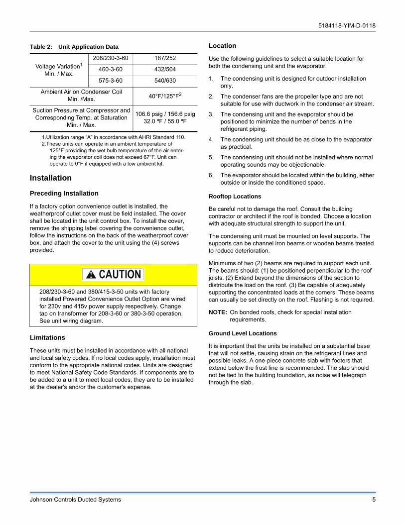
Installation
Preceding Installation
If a factory option convenience outlet is installed, the weatherproof outlet cover must be field installed. The cover shall be located in the unit control box. To install the cover, remove the shipping label covering the convenience outlet, follow the instructions on the back of the weatherproof cover box, and attach the cover to the unit using the (4) screws provided.
Limitations
These units must be installed in accordance with all national and local safety codes. If no local codes apply, installation must conform to the appropriate national codes. Units are designed to meet National Safety Code Standards. If components are to be added to a unit to meet local codes, they are to be installed at the dealer's and/or the customer's expense.
Location
Use the following guidelines to select a suitable location for both the condensing unit and the evaporator.
1. The condensing unit is designed for outdoor installation only.
2. The condenser fans are the propeller type and are not suitable for use with ductwork in the condenser air stream.
3. The condensing unit and the evaporator should be positioned to minimize the number of bends in the refrigerant piping.
4. The condensing unit should be as close to the evaporator as practical.
5. The condensing unit should not be installed where normal operating sounds may be objectionable.
6. The evaporator should be located within the building, either outside or inside the conditioned space.
Rooftop Locations
Be careful not to damage the roof. Consult the building contractor or architect if the roof is bonded. Choose a location with adequate structural strength to support the unit.
The condensing unit must be mounted on level supports. The supports can be channel iron beams or wooden beams treated to reduce deterioration.
Minimums of two (2) beams are required to support each unit. The beams should: (1) be positioned perpendicular to the roof joists. (2) Extend beyond the dimensions of the section to distribute the load on the roof. (3) Be capable of adequately supporting the concentrated loads at the corners. These beams can usually be set directly on the roof. Flashing is not required.
NOTE: On bonded roofs, check for special installation requirements.
Ground Level Locations
It is important that the units be installed on a substantial base that will not settle, causing strain on the refrigerant lines and possible leaks. A one-piece concrete slab with footers that extend below the frost line is recommended. The slab should not be tied to the building foundation, as noise will telegraph through the slab.
Table 2: Unit Application Data
Voltage Variation1
Min. / Max.
1.Utilization range “A” in accordance with AHRI Standard 110.
208/230-3-60 187/252
460-3-60 432/504
575-3-60 540/630
Ambient Air on Condenser CoilMin. /Max. 40°F/125°F2
2.These units can operate in an ambient temperature of 125°F providing the wet bulb temperature of the air enter-ing the evaporator coil does not exceed 67°F. Unit can operate to 0°F if equipped with a low ambient kit.
Suction Pressure at Compressor andCorresponding Temp. at Saturation
Min. / Max.
106.6 psig / 156.6 psig32.0 ºF / 55.0 ºF
208/230-3-60 and 380/415-3-50 units with factory installed Powered Convenience Outlet Option are wired for 230v and 415v power supply respectively. Change tap on transformer for 208-3-60 or 380-3-50 operation. See unit wiring diagram.
5184118-YIM-D-0118
6 Johnson Controls Ducted Systems
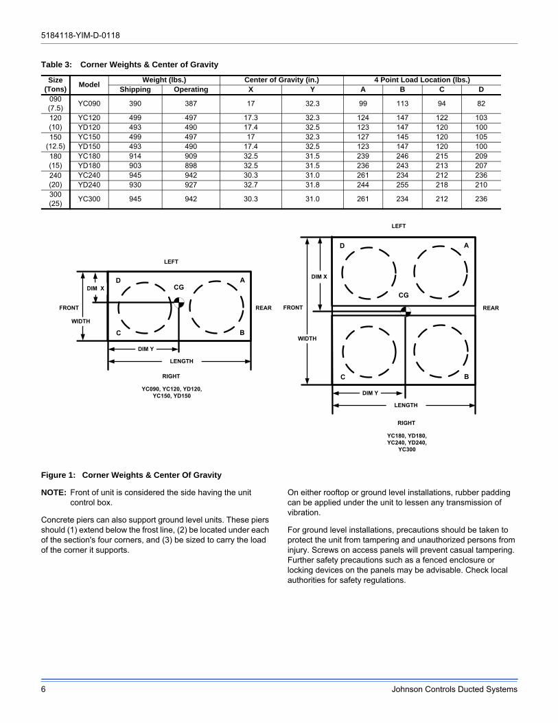
Figure 1: Corner Weights & Center Of Gravity
NOTE: Front of unit is considered the side having the unit control box.
Concrete piers can also support ground level units. These piers should (1) extend below the frost line, (2) be located under each of the section's four corners, and (3) be sized to carry the load of the corner it supports.
On either rooftop or ground level installations, rubber padding can be applied under the unit to lessen any transmission of vibration.
For ground level installations, precautions should be taken to protect the unit from tampering and unauthorized persons from injury. Screws on access panels will prevent casual tampering. Further safety precautions such as a fenced enclosure or locking devices on the panels may be advisable. Check local authorities for safety regulations.
Table 3: Corner Weights & Center of Gravity
Size(Tons)
ModelWeight (lbs.) Center of Gravity (in.) 4 Point Load Location (lbs.)
Shipping Operating X Y A B C D090(7.5)
YC090 390 387 17 32.3 99 113 94 82
120(10)
YC120 499 497 17.3 32.3 124 147 122 103YD120 493 490 17.4 32.5 123 147 120 100
150(12.5)
YC150 499 497 17 32.3 127 145 120 105YD150 493 490 17.4 32.5 123 147 120 100
180(15)
YC180 914 909 32.5 31.5 239 246 215 209YD180 903 898 32.5 31.5 236 243 213 207
240(20)
YC240 945 942 30.3 31.0 261 234 212 236YD240 930 927 32.7 31.8 244 255 218 210
300(25)
YC300 945 942 30.3 31.0 261 234 212 236
DIM X
DIM Y
LENGTH
WIDTH
C
A
B
DCG
FRONT
RIGHT
REAR
LEFT
CG
DIM X
DIM Y
LENGTH
WIDTH
C B
AD
FRONT REAR
LEFT
RIGHT
YC090, YC120, YD120,YC150, YD150
YC180, YD180,YC240, YD240,
YC300
5184118-YIM-D-0118
Johnson Controls Ducted Systems 7
Clearances
The unit must be installed with sufficient clearance for air to enter the condenser coil, for air discharge and for servicing access. See Table 4 for clearances.
NOTE: Additional clearance is required to remove the compressors out the back of the unit, unless a means is available to lift the compressor out through the top of the unit.
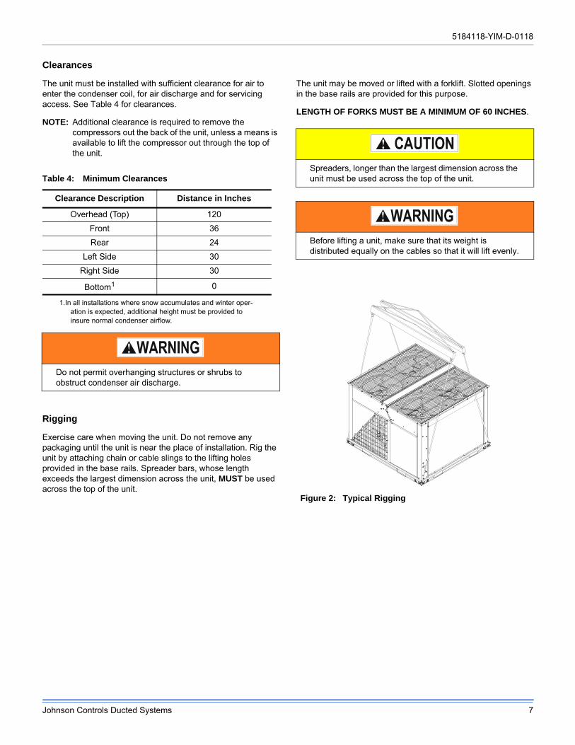
Rigging
Exercise care when moving the unit. Do not remove any packaging until the unit is near the place of installation. Rig the unit by attaching chain or cable slings to the lifting holes provided in the base rails. Spreader bars, whose length exceeds the largest dimension across the unit, MUST be used across the top of the unit.
The unit may be moved or lifted with a forklift. Slotted openings in the base rails are provided for this purpose.
LENGTH OF FORKS MUST BE A MINIMUM OF 60 INCHES.
Table 4: Minimum Clearances
Clearance Description Distance in Inches
Overhead (Top) 120
Front 36
Rear 24
Left Side 30
Right Side 30
Bottom1
1.In all installations where snow accumulates and winter oper-ation is expected, additional height must be provided to insure normal condenser airflow.
0
Do not permit overhanging structures or shrubs to obstruct condenser air discharge.
Spreaders, longer than the largest dimension across the unit must be used across the top of the unit.
Before lifting a unit, make sure that its weight is distributed equally on the cables so that it will lift evenly.
Figure 2: Typical Rigging
5184118-YIM-D-0118
8 Johnson Controls Ducted Systems
Power Wiring
Check the available power and the unit nameplate for correct voltage. Run the necessary number of properly sized wires to the unit. Provide a disconnect switch (if not included with the unit) and fusing as required (factory disconnect is a fused disconnect). Route the conduit through the large knockout located on the front of the electrical box. See Table 5 for Electrical Data.
The disconnect switch may be bolted to the side of the unit but not to any of the removable panels; this would interfere with access to the unit. Make sure that no refrigerant lines will be punctured when mounting the disconnect switch, and note that it must be suitable for outdoor installation.
Control Wiring
Route the necessary low voltage control wires from the Smart Equipment™ control board to the thermostat and also from the low voltage condenser unit control box to the terminal block inside the evaporator unit. Refer to Figures 3 thru for field wiring diagrams.
Compressors
The scroll compressors used in this product are specifically designed to operate with R-410A Refrigerant and cannot be interchanged.
The compressor also uses a polyolester (POE oil), Mobil 3MA POE. This oil is extremely hydroscopic, meaning it absorbs water readily. POE oil can absorb 15 times as much water as other oils designed for HCFC and CFC refrigerants. Take all necessary precautions to avoid exposure of the oil to the atmosphere.
POE (polyolester) compressor lubricants are known to cause long term damage to some synthetic roofing materials.
Procedures which risk oil leakage include, but are not limited to, compressor replacement, repairing refrigerant leaks, replacing refrigerant components such as filter drier, pressure switch, metering device or coil.
Units are shipped with compressor mountings which are factory adjusted and ready for operation.
Phasing
Three-phase, scroll compressors operate in only one direction. If the scroll is drawing low amperage, has similar suction and discharge pressures, or is producing a high noise level, the scroll is misphased. Change the incoming line connection phasing to obtain the proper rotation.
All power and control wiring must be in accordance with National and Local electrical codes.
This system uses R-410A Refrigerant which operates at higher pressures than R-22. No other refrigerant may be used in this system.
Do not leave the system open to the atmosphere. Unit damage could occur due to moisture being absorbed by the POE oil in the system. This type of oil is highly susceptible to moisture absorption
Exposure, even if immediately cleaned up, may cause embrittlement (leading to cracking) to occur in one year or more. When performing any service that may risk exposure of compressor oil to the roof, take precautions to protect roofing.
Do not loosen compressor mounting bolts.
Scroll compressors require proper rotation to operate properly. Failure to check and correct rotation may result in property damage.
5184118-YIM-D-0118
Johnson Controls Ducted Systems 9
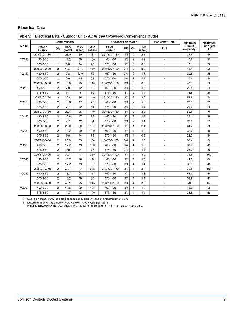
Electrical Data
Table 5: Electrical Data - Outdoor Unit - AC Without Powered Convenience Outlet
Model
Compressors Outdoor Fan Motor Pwr Conv Outlet MinimumCircuit
Ampacity1
MaximumFuse Size
(A)2PowerSupply
QtyRLA
(each)MCC
(each)LRA
(each)PowerSupply
HP QtyFLA
(each)FLA
YC090
208/230-3-60 1 25.0 39 164 208/230-1-60 1/3 2 2.1 - 35.5 45
460-3-60 1 12.2 19 100 460-1-60 1/3 2 1.2 - 17.6 25
575-3-60 1 9.0 14 78 575-1-60 1/3 2 0.9 - 13.1 20
YC120
208/230-3-60 2 15.7 24.5 110 208/230-1-60 3/4 2 3.0 - 41.4 50
460-3-60 2 7.8 12.0 52 460-1-60 3/4 2 1.6 - 20.8 25
575-3-60 2 5.8 9.1 39 575-1-60 3/4 2 1.4 - 15.8 20
YD120
208/230-3-60 2 16.0 25 110 208/230-1-60 3/4 2 3.0 - 42.1 50
460-3-60 2 7.8 12 52 460-1-60 3/4 2 1.6 - 20.8 25
575-3-60 2 5.7 9 39 575-1-60 3/4 2 1.4 - 15.5 20
YC150
208/230-3-60 2 22.4 35 149 208/230-1-60 3/4 2 3.0 - 56.5 70
460-3-60 2 10.6 17 75 460-1-60 3/4 2 1.6 - 27.1 35
575-3-60 2 7.7 12 54 575-1-60 3/4 2 1.4 - 20.0 25
YD150
208/230-3-60 2 22.4 35 149 208/230-1-60 3/4 2 3.0 - 56.5 70
460-3-60 2 10.6 17 75 460-1-60 3/4 2 1.6 - 27.1 35
575-3-60 2 7.7 12 54 575-1-60 3/4 2 1.4 - 20.0 25
YC180
208/230-3-60 2 25.0 39 164 208/230-1-60 1/3 4 2.1 - 64.7 80
460-3-60 2 12.2 19 100 460-1-60 1/3 4 1.2 - 32.2 40
575-3-60 2 9.0 14 78 575-1-60 1/3 4 0.9 - 24.0 30
YD180
208/230-3-60 2 25.0 39 164 208/230-1-60 3/4 4 3.0 - 68.4 90
460-3-60 2 12.2 19 100 460-1-60 3/4 4 1.6 - 33.9 45
575-3-60 2 9.0 14 78 575-1-60 3/4 4 1.4 - 25.7 30
YC240
208/230-3-60 2 30.1 47 225 208/230-1-60 3/4 4 3.0 - 79.8 100
460-3-60 2 16.7 26 114 460-1-60 3/4 4 1.6 - 44.0 60
575-3-60 2 12.2 19 80 575-1-60 3/4 4 1.4 - 32.9 45
YD240
208/230-3-60 2 30.1 47 225 208/230-1-60 3/4 4 3.0 - 79.8 100
460-3-60 2 16.7 26 114 460-1-60 3/4 4 1.6 - 44.0 60
575-3-60 2 12.2 19 80 575-1-60 3/4 4 1.4 - 32.9 45
YC300
208/230-3-60 2 48.1 75 245 208/230-1-60 3/4 4 3.0 - 120.3 150
460-3-60 2 18.6 29 125 460-1-60 3/4 4 1.6 - 48.3 60
575-3-60 2 14.7 23 100 575-1-60 3/4 4 1.4 - 38.5 50
1. Based on three, 75°C insulated copper conductors in conduit and ambient of 30°C.2. Maximum fuse or maximum circuit breaker (HACR type per NEC).
Refer to NEC/NFPA No. 70, Articles 440-11, 12 for information on minimum disconnect sizing.
5184118-YIM-D-0118
10 Johnson Controls Ducted Systems
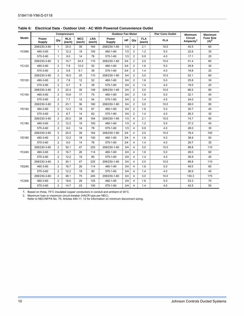
Table 6: Electrical Data - Outdoor Unit - AC With Powered Convenience Outlet
Model
Compressors Outdoor Fan Motor Pwr Conv Outlet MinimumCircuit
Ampacity1
MaximumFuse Size
(A)2PowerSupply
QtyRLA
(each)MCC
(each)LRA
(each)PowerSupply
HP QtyFLA
(each)FLA
YC090
208/230-3-60 1 25.0 39 164 208/230-1-60 1/3 2 2.1 10.0 45.5 60
460-3-60 1 12.2 19 100 460-1-60 1/3 2 1.2 5.0 22.6 30
575-3-60 1 9.0 14 78 575-1-60 1/3 2 0.9 4.0 17.1 25
YC120
208/230-3-60 2 15.7 24.5 110 208/230-1-60 3/4 2 3.0 10.0 51.4 60
460-3-60 2 7.8 12.0 52 460-1-60 3/4 2 1.6 5.0 25.8 30
575-3-60 2 5.8 9.1 39 575-1-60 3/4 2 1.4 4.0 19.8 25
YD120
208/230-3-60 2 16.0 25 110 208/230-1-60 3/4 2 3.0 10.0 52.1 60
460-3-60 2 7.8 12 52 460-1-60 3/4 2 1.6 5.0 25.8 30
575-3-60 2 5.7 9 39 575-1-60 3/4 2 1.4 4.0 19.5 25
YC150
208/230-3-60 2 22.4 35 149 208/230-1-60 3/4 2 3.0 10.0 66.5 80
460-3-60 2 10.6 17 75 460-1-60 3/4 2 1.6 5.0 32.1 40
575-3-60 2 7.7 12 54 575-1-60 3/4 2 1.4 4.0 24.0 30
YD150
208/230-3-60 2 23.1 36 160 208/230-1-60 3/4 2 3.0 10.0 68.0 90
460-3-60 2 12.2 19 87 460-1-60 3/4 2 1.6 5.0 35.7 45
575-3-60 2 8.7 14 62 575-1-60 3/4 2 1.4 4.0 26.3 30
YC180
208/230-3-60 2 25.0 39 164 208/230-1-60 1/3 4 2.1 10.0 74.7 90
460-3-60 2 12.2 19 100 460-1-60 1/3 4 1.2 5.0 37.2 45
575-3-60 2 9.0 14 78 575-1-60 1/3 4 0.9 4.0 28.0 35
YD180
208/230-3-60 2 25.0 39 164 208/230-1-60 3/4 4 3.0 10.0 78.4 100
460-3-60 2 12.2 19 100 460-1-60 3/4 4 1.6 5.0 38.9 50
575-3-60 2 9.0 14 78 575-1-60 3/4 4 1.4 4.0 29.7 35
YC240
208/230-3-60 2 30.1 47 225 208/230-1-60 3/4 4 3.0 10.0 89.8 110
460-3-60 2 16.7 26 114 460-1-60 3/4 4 1.6 5.0 49.0 60
575-3-60 2 12.2 19 80 575-1-60 3/4 4 1.4 4.0 36.9 45
YD240
208/230-3-60 2 30.1 47 225 208/230-1-60 3/4 4 3.0 10.0 89.8 110
460-3-60 2 16.7 26 114 460-1-60 3/4 4 1.6 5.0 49.0 60
575-3-60 2 12.2 19 80 575-1-60 3/4 4 1.4 4.0 36.9 45
YC300
208/230-3-60 2 48.1 75 245 208/230-1-60 3/4 4 3.0 10.0 130.3 175
460-3-60 2 18.6 29 125 460-1-60 3/4 4 1.6 5.0 53.3 70
575-3-60 2 14.7 23 100 575-1-60 3/4 4 1.4 4.0 42.5 50
1. Based on three, 75°C insulated copper conductors in conduit and ambient of 30°C.2. Maximum fuse or maximum circuit breaker (HACR type per NEC).
Refer to NEC/NFPA No. 70, Articles 440-11, 12 for information on minimum disconnect sizing.
5184118-YIM-D-0118
Johnson Controls Ducted Systems 11
Refrigerant Mains
Line Sizing
When sizing refrigerant pipe for a split-system air conditioner, check the following:
1. Suction line pressure drop due to friction.
2. Liquid line pressure drop due to friction.
3. Suction line velocity for oil return.
4. Liquid line pressure drop due to vertical rise. For certain piping arrangements, different sizes of suction line pipe may have to be used. The velocity of the refrigerant vapor must always be great enough to carry the oil back to the compressor.
5. Evaporator Located Below Condenser - On a split system where the evaporator blower is located below the condenser, the suction line must be sized for both pressure drop and for oil return.
6. Condenser Located Below Evaporator - When the condenser is located below the evaporator blower, the liquid line must be designed for the pressure drop due to both friction loss and vertical rise. If the pressure drop due to vertical rise and friction exceeds 60 psi, some refrigerant will flash before it reaches the thermal expansion valve.
Flash gas:
1. Increases the liquid line pressure loss due to friction that in turn causes further flashing.
2. Reduces the capacity of the refrigerant control device which starves the evaporator.
3. Erodes the seat of the refrigerant control device.
4. Causes erratic control of the refrigerant entering the evaporator.
Take Adequate Precautions
Many service problems can be avoided by taking adequate precautions to provide an internally clean and dry system and by using procedures and materials that conform to established standards.
Use hard drawn copper tubing where no appreciable amount of bending around pipes or other obstructions is necessary. If soft copper is used, care should be taken to avoid sharp bends that may cause a restriction. Pack fiberglass insulation and a sealing material such as permagum around refrigerant lines where they penetrate a wall to reduce vibrations and to retain some flexibility.
Support all tubing at minimum intervals with suitable hangers, brackets or clamps.
Braze all copper-to-copper joints with Silfos-5 or equivalent brazing material. Do not use soft solder. Insulate all suction lines with a minimum of 1/2" ARMAFLEX or equivalent that meets local codes. Liquid lines exposed to direct sunlight and/or high temperatures must also be insulated. Never solder suction and liquid lines together. They can be taped together for convenience and support purposes, but they must be completely insulated from each other.
The liquid and suction service ports on the condenser section permit leak testing, evacuation, and partial charging of the field piping and the evaporator without disturbing refrigerant stored in the condenser during initial installation.
Before beginning installation of the main lines, be sure that the evaporator section has not developed a leak in transit. Check pressure at the Schrader valve located on the header of each coil. If pressure still exists in the system, it can be assumed to be leak free. If pressure DOES NOT exist the section will need to be repaired before evacuation and charging is performed.
A filter-drier MUST be field-installed in the liquid line of every system to prevent dirt and moisture from damaging the system. Properly sized filter-driers are shipped with each condensing section.
NOTE: Installing a filter-drier does not eliminate the need for the proper evacuation of a system before it is charged.
A field-installed moisture indicating sight-glass should be installed in the liquid line(s) between the filter-drier and the evaporator coil. The moisture indicating sight-glass can be used to check for excess moisture in the system.
Both condenser and evaporator sections have copper sealing disks brazed over the end of liquid and suction connections. The temperature required to make or break a brazed joint is high enough to cause oxidation of the copper unless an inert atmosphere is provided.
NOTE: Dry nitrogen should flow through the system at all times when heat is being applied and until the joint has
This Split-System (Air Condensing / Heat Pump / Air Handling) unit is one component of an entire system. As such it requires specific application considerations with regard to the rest of the system (air handling unit, duct design, condensing unit, refrigerant piping and control scheme).
Failure to properly apply this equipment with the rest of the system may result in premature failure and/or reduced performance / increased costs. Warranty coverage specifically excludes failures due to improper application and Ducted Systems specifically disclaims any liability resulting from improper application.
Please refer to the equipment Technical Guide, Installation Manual and the piping applications bulletin 247077 or call the applications department for Ducted Systems @ 1-877-874-SERV for guidance.
5184118-YIM-D-0118
12 Johnson Controls Ducted Systems
cooled. The flow of nitrogen will prevent oxidation of the copper lines during installation.
Always punch a small hole in sealing disks before unbrazing to prevent the pressure in the line from blowing them off. Do not use a drill as copper shavings can enter system.
NOTE: Solenoid and hot gas bypass valves (if used) should be opened manually or electrically during brazing or evacuating.
NOTE: Schrader valves located on unit service valves should have their stem removed during brazing to prevent damage to the valve.
Start Installation
Start Installation of main lines at the condenser unit. Verify the service valves are fully seated by screwing the stem of both valves down into the valve body until it stops. Remove the Schrader valve stem and connect a low-pressure nitrogen source to the service port on the suction line valve body. Punch a small hole in the sealing disk; the flow of nitrogen will prevent any debris from entering the system. Wrap the valve body with a wet rag to prevent overheating during the brazing process. Overheating the valve will damage the valve seals. Unbraze the sealing disk, cool the valve body and prepare the joint for connections of the main lines. Repeat for the liquid line valve body.
Connect the main liquid line to the liquid line service valve on the condenser section, while maintaining a flow of nitrogen. Cool the valve body and replace the Schrader valve stem on the service port of the liquid line service valve.
Install the liquid line from the condenser unit to the evaporator liquid connection, maintaining a flow of nitrogen during all brazing operations.
The filter-drier and sight glass must be located in this line, leaving the O.D. unit.
Connect a low-pressure nitrogen source to the Schrader valve located on the evaporator unit coil headers. Punch a small hole in the sealing disks, the flow of nitrogen will prevent any debris from entering the system. Unbraze both liquid and suction sealing disks and prepare the joints for connections of the main lines.
Connect the main liquid line to the liquid line connection on the evaporator unit, while maintaining a flow of nitrogen.
Make the suction line connection at the evaporator and run the line to the condenser unit. Connect the main suction line to the
suction line service line on the condenser unit, while maintaining a flow of nitrogen. Cool the valve body and replace the Schrader valve stem on the service port of the suction line service valve.
Once the brazing process is complete, leak testing should be done on all interconnecting piping and the evaporator before proper evacuation to 500 microns is performed. Once the line set and evaporator unit is properly evacuated the service valves can be opened and the condenser unit is now ready to charge with the appropriate weight of refrigerant.
Calculate the correct system charge for the condenser unit, the evaporator unit and the field line set. Charge the system by introducing liquid refrigerant into the liquid line through the liquid port connection. Complete adding the refrigerant in vapor form into the suction port when the compressor is started.
The correct refrigerant pressures are indicated as shown in Figures 16 through 25.
NOTE: This instruction covers the installation and operation of the basic condenser unit. For refrigerant piping installation instructions refer to document 247077 "Application Data - General Piping Recommendations for Split System Air Conditioning and Heat Pumps".
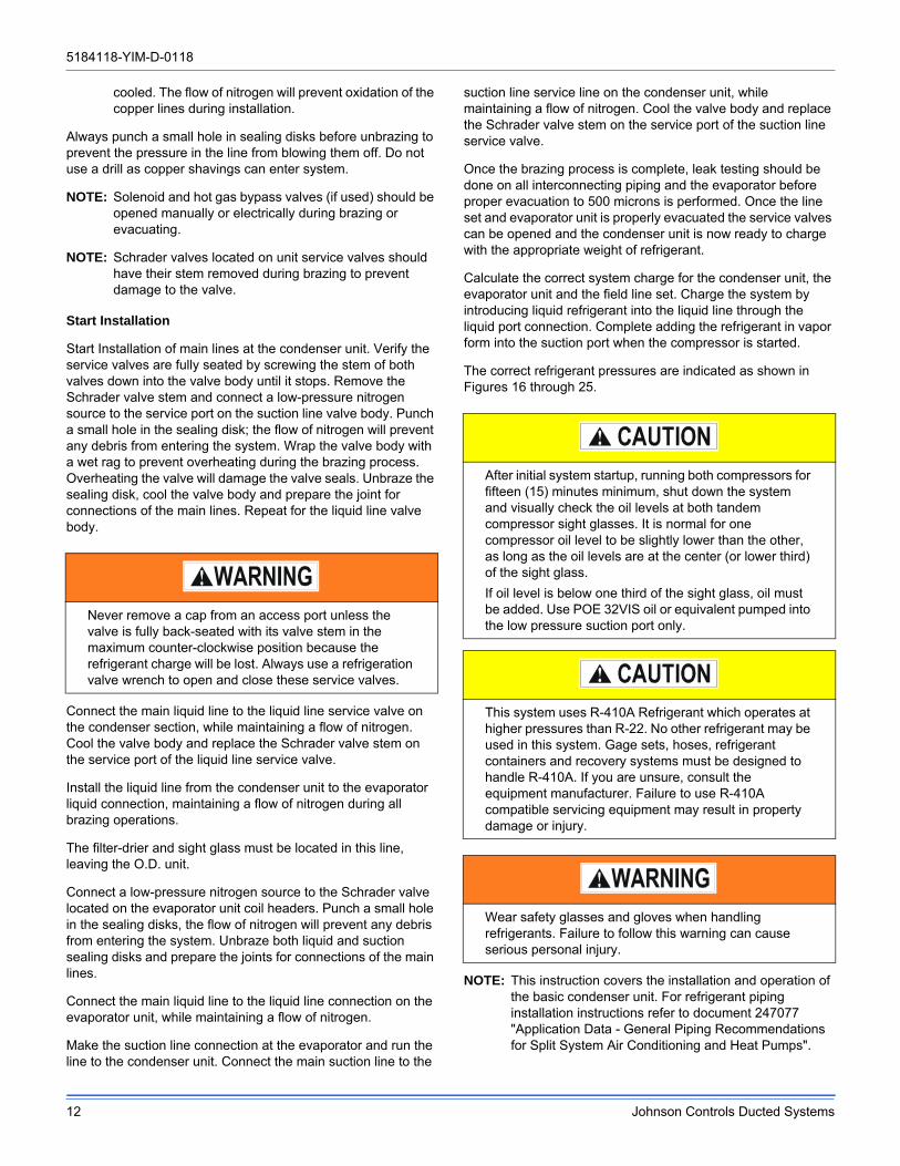
Never remove a cap from an access port unless the valve is fully back-seated with its valve stem in the maximum counter-clockwise position because the refrigerant charge will be lost. Always use a refrigeration valve wrench to open and close these service valves.
After initial system startup, running both compressors for fifteen (15) minutes minimum, shut down the system and visually check the oil levels at both tandem compressor sight glasses. It is normal for one compressor oil level to be slightly lower than the other, as long as the oil levels are at the center (or lower third) of the sight glass.
If oil level is below one third of the sight glass, oil must be added. Use POE 32VIS oil or equivalent pumped into the low pressure suction port only.
This system uses R-410A Refrigerant which operates at higher pressures than R-22. No other refrigerant may be used in this system. Gage sets, hoses, refrigerant containers and recovery systems must be designed to handle R-410A. If you are unsure, consult the equipment manufacturer. Failure to use R-410A compatible servicing equipment may result in property damage or injury.
Wear safety glasses and gloves when handling refrigerants. Failure to follow this warning can cause serious personal injury.
5184118-YIM-D-0118
Johnson Controls Ducted Systems 13
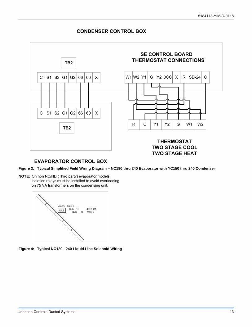
Figure 3: Typical Simplified Field Wiring Diagram – NC180 thru 240 Evaporator with YC150 thru 240 Condenser
NOTE: On non NC/ND (Third party) evaporator models, isolation relays must be installed to avoid overloading on 75 VA transformers on the condensing unit.
Figure 4: Typical NC120 - 240 Liquid Line Solenoid Wiring
C S1 S2 G1 G2 66 60 X
C S1 S2 G1 G2 66 60 X W1 W2 Y1 G Y2 0CC CX R SD-24
SE CONTROL BOARD THERMOSTAT CONNECTIONSTB2
TB2
CONDENSER CONTROL BOX
EVAPORATOR CONTROL BOX
THERMOSTAT TWO STAGE COOL TWO STAGE HEAT
R C Y1 Y2 G W1 W2
219 / Y218 / BR
1LLS
VALVE SYS 2BLK
BLK
C O I L
5184118-YIM-D-0118
14 Johnson Controls Ducted Systems
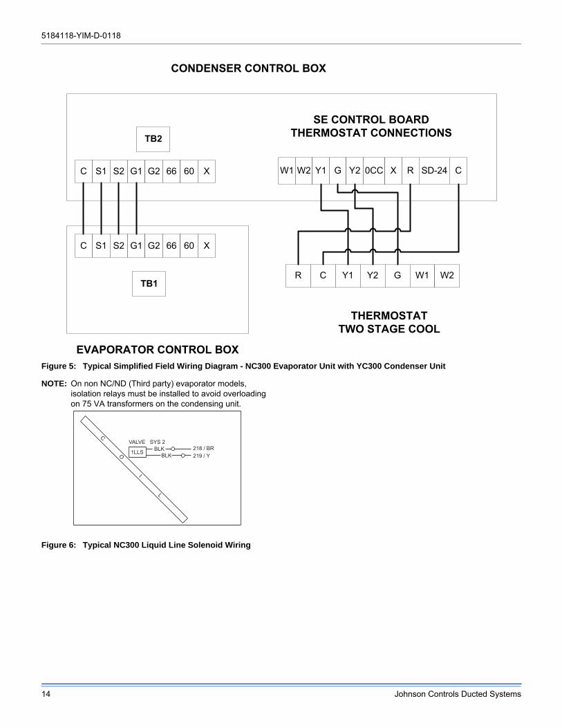
Figure 5: Typical Simplified Field Wiring Diagram - NC300 Evaporator Unit with YC300 Condenser Unit
NOTE: On non NC/ND (Third party) evaporator models, isolation relays must be installed to avoid overloading on 75 VA transformers on the condensing unit.
Figure 6: Typical NC300 Liquid Line Solenoid Wiring
W1 W2 Y1 G Y2 0CC CX R SD-24
SE CONTROL BOARD THERMOSTAT CONNECTIONSTB2
TB1
CONDENSER CONTROL BOX
EVAPORATOR CONTROL BOX
THERMOSTAT TWO STAGE COOL
R C Y1 Y2 G W1 W2
C S1 S2 G1 G2 66 60 X
C S1 S2 G1 G2 66 60 X
219 / Y218 / BR
1LLS
VALVE SYS 2BLK
BLK
C O I L
5184118-YIM-D-0118
Johnson Controls Ducted Systems 15
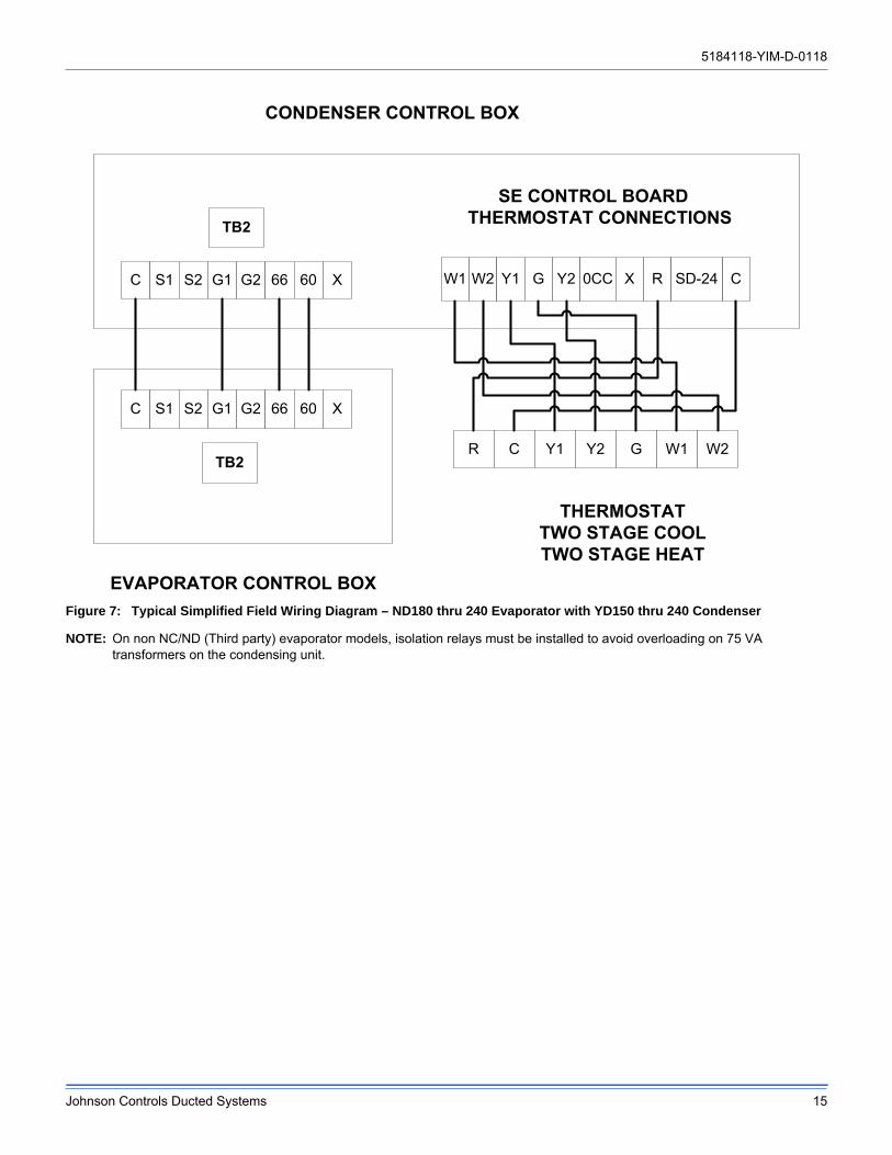
Figure 7: Typical Simplified Field Wiring Diagram – ND180 thru 240 Evaporator with YD150 thru 240 Condenser
NOTE: On non NC/ND (Third party) evaporator models, isolation relays must be installed to avoid overloading on 75 VA transformers on the condensing unit.
C S1 S2 G1 G2 66 60 X
C S1 S2 G1 G2 66 60 X W1 W2 Y1 G Y2 0CC CX R SD-24
SE CONTROL BOARD THERMOSTAT CONNECTIONSTB2
TB2
CONDENSER CONTROL BOX
EVAPORATOR CONTROL BOX
THERMOSTAT TWO STAGE COOL TWO STAGE HEAT
R C Y1 Y2 G W1 W2
5184118-YIM-D-0118
16 Johnson Controls Ducted Systems
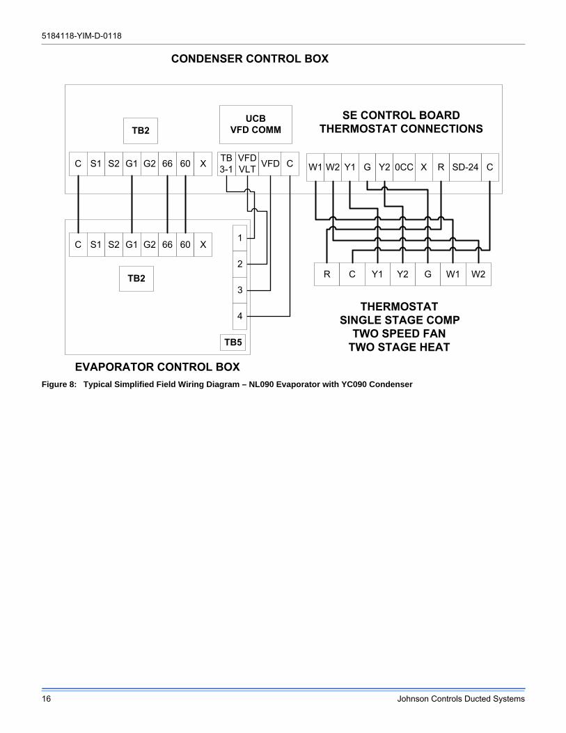
Figure 8: Typical Simplified Field Wiring Diagram – NL090 Evaporator with YC090 Condenser
CONDENSER CONTROL BOX
EVAPORATOR CONTROL BOX
THERMOSTATSINGLE STAGE COMP
TWO SPEED FANTWO STAGE HEAT
W1 W2 Y1 G Y2 0CC CX R SD-24
SE CONTROL BOARD THERMOSTAT CONNECTIONS
R C Y1 Y2 G W1 W2
UCBVFD COMM
TB5
VFDVLT VFD C
1
2
3
4
C S1 S2 G1 G2 66 60 X
C S1 S2 G1 G2 66 60 X
TB2
TB2
TB3-1

5184118-YIM-D-0118
Johnson Controls Ducted Systems 17
Figure 9: Typical Simplified Field Wiring Diagram – NL120 thru 240 Evaporator with YC120 thru 240 Condenser
NOTE: On non NL/NM (Third Party) evaporator models, isolation relays must be installed to avoid overloading on 75 VA transformers on the condensing unit.
Figure 10: Typical NL120 - 240 Liquid Line Solenoid Wiring
C S1 S2 G1 G2 66 60 X
C S1 S2 G1 G2 66 60 X W1 W2 Y1 G Y2 0CC CX R SD-24
SE CONTROL BOARD THERMOSTAT CONNECTIONSTB2
TB2
CONDENSER CONTROL BOX
EVAPORATOR CONTROL BOX
THERMOSTATTWO STAGE COOL/FAN
TWO STAGE HEAT
R C Y1 Y2 G W1 W2
UCBVFD COMM
TB5
VFDVLT VFD C
1
2
3
4
TB3-1
219 / Y218 / BR
1LLS
VALVE SYS 2BLK
BLK
C O I L
5184118-YIM-D-0118
18 Johnson Controls Ducted Systems
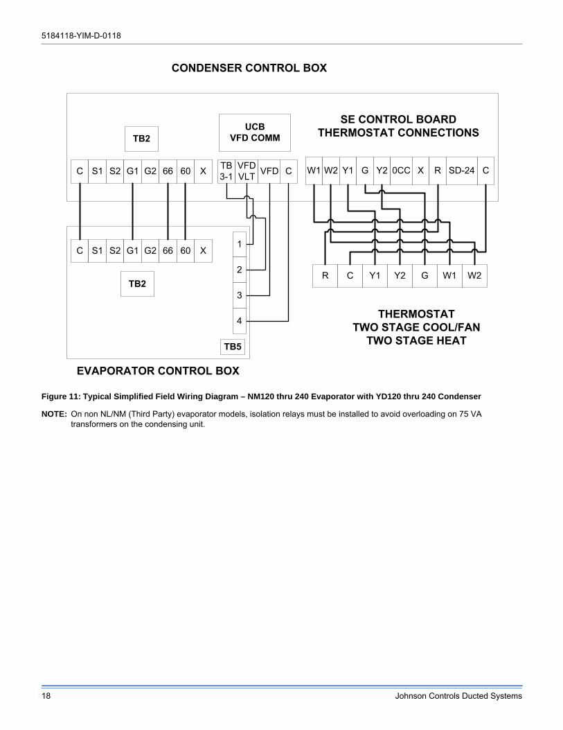
Figure 11: Typical Simplified Field Wiring Diagram – NM120 thru 240 Evaporator with YD120 thru 240 Condenser
NOTE: On non NL/NM (Third Party) evaporator models, isolation relays must be installed to avoid overloading on 75 VA transformers on the condensing unit.
CONDENSER CONTROL BOX
EVAPORATOR CONTROL BOX
C S1 S2 G1 G2 66 60 X
C S1 S2 G1 G2 66 60 X
TB2
TB2
UCBVFD COMM
TB5
VFDVLT VFD C
1
2
3
4
W1 W2 Y1 G Y2 0CC CX R SD-24
SE CONTROL BOARD THERMOSTAT CONNECTIONS
THERMOSTATTWO STAGE COOL/FAN
TWO STAGE HEAT
R C Y1 Y2 G W1 W2
TB3-1
5184118-YIM-D-0118
Johnson Controls Ducted Systems 19
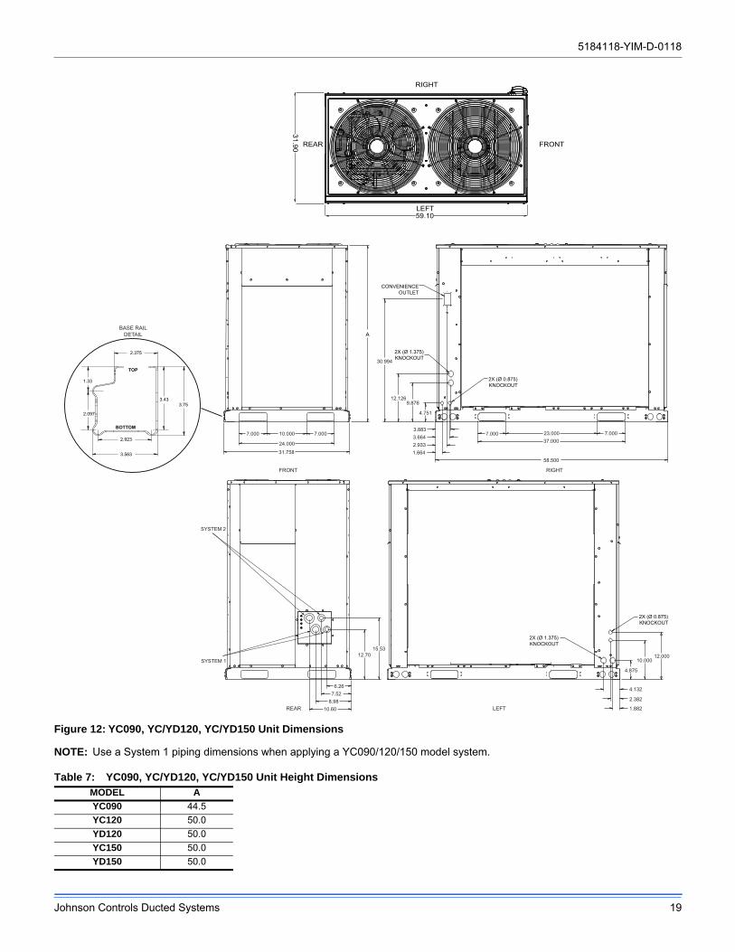
Figure 12: YC090, YC/YD120, YC/YD150 Unit Dimensions
NOTE: Use a System 1 piping dimensions when applying a YC090/120/150 model system.
Table 7: YC090, YC/YD120, YC/YD150 Unit Height DimensionsMODEL A
YC090 44.5
YC120 50.0
YD120 50.0
YC150 50.0
YD150 50.0
LEFT
REAR
RIGHT
FRONT
RIGHT
2X (Ø 0.875)KNOCKOUT
30.994
2X (Ø 1.375)KNOCKOUT
CONVENIENCEOUTLET
7.00010.000
24.000
31.758
7.0003.8833.6642.9331.664
23.00037.000
58.500
7.0007.000
12.1269.876
4.751
A
2X (Ø 1.375)KNOCKOUT
REAR LEFT
2X (Ø 0.875)KNOCKOUT
12.00010.000
4.875
4.132
2.382
1.882
15.5312.70
6.267.52
8.9810.60
SYSTEM 2
SYSTEM 1
FRONT
31.90
59.10
BASE RAILDETAIL
2.923
3.563
2.375
3.753.43
TOP
BOTTOM
1.33
2.097
5184118-YIM-D-0118
20 Johnson Controls Ducted Systems
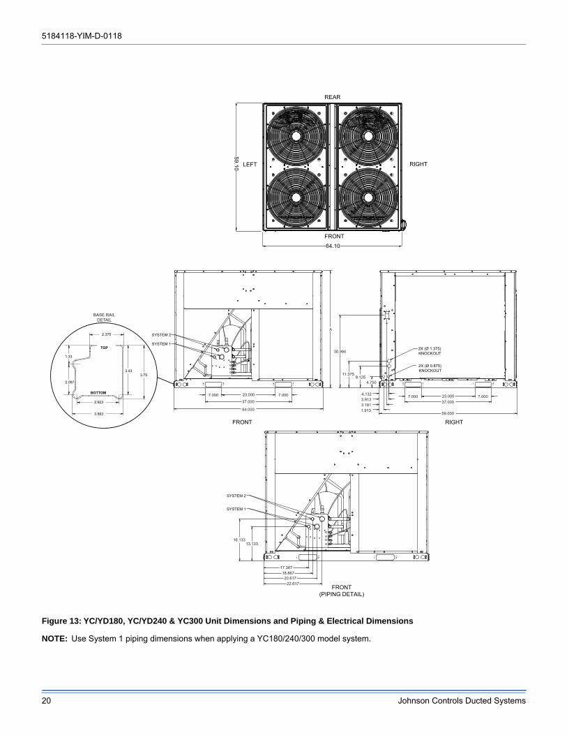
Figure 13: YC/YD180, YC/YD240 & YC300 Unit Dimensions and Piping & Electrical Dimensions
NOTE: Use System 1 piping dimensions when applying a YC180/240/300 model system.
LEFT RIGHT
FRONT
REAR
FRONT
FRONT(PIPING DETAIL)
RIGHT
SYSTEM 2
SYSTEM 1
7.0007.000 23.000
37.000
64.000
2X (Ø 0.875)KNOCKOUT
2X (Ø 1.375)KNOCKOUT
7.0007.000 23.00037.000
59.000
30.994
11.3759.125
4.750
4.1323.9133.1811.913
A
SYSTEM 2
SYSTEM 1
16.13313.133
17.36718.86720.617
22.617
59.10
64.10
BASE RAILDETAIL
2.923
3.563
2.375
3.753.43
TOP
BOTTOM
1.33
2.097
5184118-YIM-D-0118
Johnson Controls Ducted Systems 21
YC3
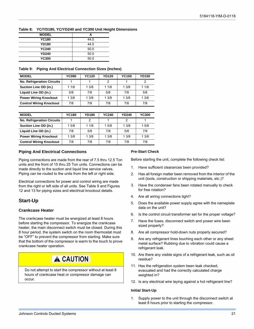
Piping And Electrical Connections
Piping connections are made from the rear of 7.5 thru 12.5 Ton units and the front of 15 thru 25 Ton units. Connections can be made directly to the suction and liquid line service valves. Piping can be routed to the units from the left or right side.
Electrical connections for power and control wiring are made from the right or left side of all units. See Table 9 and Figures 12 and 13 for piping sizes and electrical knockout details.
Start-Up
Crankcase Heater
The crankcase heater must be energized at least 8 hours before starting the compressor. To energize the crankcase heater, the main disconnect switch must be closed. During this 8 hour period, the system switch on the room thermostat must be “OFF” to prevent the compressor from starting. Make sure that the bottom of the compressor is warm to the touch to prove crankcase heater operation.
Pre-Start Check
Before starting the unit, complete the following check list:
1. Have sufficient clearances been provided?
2. Has all foreign matter been removed from the interior of the unit (tools, construction or shipping materials, etc.)?
3. Have the condenser fans been rotated manually to check for free rotation?
4. Are all wiring connections tight?
5. Does the available power supply agree with the nameplate data on the unit?
6. Is the control circuit transformer set for the proper voltage?
7. Have the fuses, disconnect switch and power wire been sized properly?
8. Are all compressor hold-down nuts properly secured?
9. Are any refrigerant lines touching each other or any sheet metal surface? Rubbing due to vibration could cause a refrigerant leak.
10. Are there any visible signs of a refrigerant leak, such as oil residue?
11. Has the refrigeration system been leak checked, evacuated and had the correctly calculated charge weighted in?
12. Is any electrical wire laying against a hot refrigerant line?
Initial Start-Up
1. Supply power to the unit through the disconnect switch at least 8 hours prior to starting the compressor.
Table 8: YC/YD180, YC/YD240 and YC300 Unit Height DimensionsMODEL A
YC180 44.5
YD180 44.5
YC240 50.0
YD240 50.0
YC300 50.0
Table 9: Piping And Electrical Connection Sizes (Inches)
MODEL YC090 YC120 YD120 YC150 YD150
No. Refrigeration Circuits 1 1 2 1 2
Suction Line OD (in.) 1 1/8 1 3/8 1 1/8 1 3/8 1 1/8
Liquid Line OD (in.) 5/8 7/8 5/8 7/8 5/8
Power Wiring Knockout 1 3/8 1 3/8 1 3/8 1 3/8 1 3/8
Control Wiring Knockout 7/8 7/8 7/8 7/8 7/8
MODEL YC180 YD180 YC240 YD240 YC300
No. Refrigeration Circuits 1 2 1 2 1
Suction Line OD (in.) 1 5/8 1 1/8 1 5/8 1 3/8 1 5/8
Liquid Line OD (in.) 7/8 5/8 7/8 5/8 7/8
Power Wiring Knockout 1 3/8 1 3/8 1 3/8 1 3/8 1 3/8
Control Wiring Knockout 7/8 7/8 7/8 7/8 7/8
Do not attempt to start the compressor without at least 8 hours of crankcase heat or compressor damage can occur.
5184118-YIM-D-0118
22 Johnson Controls Ducted Systems
2. Move the system switch on the thermostat to the AUTO or COOL position.
3. Reduce the setting of the room thermostat to energize the compressor.
4. Check the operation of the evaporator unit per the manufacturer’s recommendations.
5. With an ammeter, check the compressor amps against the unit data plate.
6. Check for refrigerant leaks.
7. Check for any abnormal noises and/or vibrations, and make the necessary adjustments to correct fan blade(s) touching shroud, refrigerant lines hitting on sheet metal, etc.
8. After the unit has been operating for several minutes, shut off the main power supply at the disconnect switch and inspect all factory wiring connections and bolted surfaces for tightness.
Operation
Unit Control Overview
These series of condenser unit, come factory equipped with Smart Equipment™ controls to monitor all unit functionality and safety controls.
Safety Controls
The Smart Equipment™ control board incorporates features to monitor safety circuits as well as minimize compressor wear and damage. An anti-short cycle delay (ASCD) is utilized to prevent operation of a compressor too soon after its previous run. Additionally, a minimum run time is imposed anytime a compressor is energized to allow proper oil return to the compressor. The ASCD is initiated on unit start-up and on any compressor reset or lockout.
The Smart Equipment™ control board monitors the following inputs for each cooling system:
• A high-pressure switch is factory installed to protect against excessive discharge pressure due to a blocked condenser coil or a condenser fan motor failure. During cooling operation, if a high-pressure limit switch opens, the Smart Equipment™ control board will de-energize the associated compressors and initiate the 5-minute ASCD. If the call for cool is still present at the end of the ASCD, the control board will re-energize the halted compressor. If a high-pressure switch opens three times within two hours of operation, the Smart Equipment™ control board will lockout the associated system compressors and will deliver an error message on the LCD.
• A low-pressure switch to protect the unit against excessively low suction pressure is standard on all condensing units. If the low-pressure switch opens during normal operation, the Smart Equipment™ control board will de-energize the compressor, initiate the ASCD, and
shut down the condenser fans. On startup, if the low-pressure switch opens, the Smart Equipment™ control board will monitor the low-pressure switch to make sure it closes within one minute. If it fails to close, the unit will shut down the associated compressor and begin an ASCD. If the call for cool is still present at the end of the anti-short cycle time delay, the control board will re-energize the halted compressor. If a low-pressure switch opens three times within one hour of operation, the Smart Equipment™ control board will lock-out the associated compressor and will deliver an error message on the LCD.
• An ambient air sensor will lock out mechanical cooling at 45F. A factory equipped low ambient option allows the unit to operate down to 0F. A field installed low ambient kit is also available.
The refrigerant systems are independently monitored and controlled. On any fault, only the associated system will be affected by any safety/preventive action. The other refrigerant system will continue to operate unless it is affected by the fault as well.
Sequence of Operation
Continuous Blower
By setting the room thermostat to “ON,” the low voltage control circuit from the “R” to “G” is completed and the supply air blower will operate continuously.
Intermittent Blower
With the room thermostat fan switch set to “AUTO” and the system switch set to either the “AUTO” or “HEAT” settings, the blower is energized whenever a cooling or heating operation is requested. The blower is energized after any specified delay associated with the operation.
When energized in cooling mode, the indoor blower has a minimum run time of 30 seconds. Additionally, the indoor blower has a delay of 10 seconds between operations.
Cooling Sequence Of Operation
Single-Stage Condensing Unit (YC090)
A single stage cooling thermostat is required to operate the condenser unit.
NOTE: Single-Stage Condensing Unit (YC090) matched with a Two Speed Air Handling Unit (NL090) requires a two stage cooling thermostat.
When the thermostat calls for cooling (Y1), UCB closes the coils of relay RY1 and contactors M1 and M3.
• Relay RY1 controls the crankcase heater (CCH1). The normally closed contacts allow CCH1 to operate during unit shutdown.
• Contactor M1 controls compressor COMPR1.
• Contactor M3 controls outdoor fans ODFAN1 & 2.
5184118-YIM-D-0118
Johnson Controls Ducted Systems 23
After completing the specified time for fan on-delay, UCB closes the coil of relay BR1.
• Relay BR1 sends a 24V signal to G1 of terminal block TB2. It may be used to control operation of an indoor blower.
When the call for cooling (Y1) is satisfied, the UCB disables the signal to RY1, M1 and M3 as long as the specified minimum run time (ASCD) has elapsed.
The UCB disables the signal to BR1 after completing the fan off-delay period.
Dual Stage Condenser Unit (YC120-300 or YD120-150)
A two stage cooling thermostat is required to operate the condenser unit.
• When the thermostat calls for first-stage cooling (Y1), the UCB closes the coils of relays RY1 and BR1 and contactor M1.
• Relay RY1 has three functions. 1) control the crankcase heater CCH1. 2) control the coil of contactor M3. 3) control the 24V output signal to S1 on terminal block TB2.
• Relay BR1 sends a 24V signal to G1 of terminal block TB2. It may be used to control operation of an indoor blower.
• Contactor M1 controls compressor COMPR1.
• Contactor M3 controls all outdoor fans.
When the thermostat calls for second-stage cooling (Y2), the UCB closes the coils of relays RY2 and BR2 and contactor M2.
• Relay RY2 has three functions. 1) control the crankcase heater CCH2. 2) control the coil of contactor M3. 3) control the 24V output signal to S2 on terminal block TB2.
• Relay BR2 sends a 24V signal to G2 of terminal block TB2. It may be used to control operation of an indoor blower.
• Contactor M2 controls compressor COMPR2.
If the initial call for cooling requires both stages (Y1 and Y2), the UCB will delay the second stage by 30 seconds to avoid an excessive power inrush.
When the call for cooling (Y2) is satisfied, the UCB disables the signal to RY2, BR2, and M2 as long as the specified minimum run time (ASCD) has elapsed.
When the call for cooling (Y1) is satisfied, the UCB disables the signal to RY1, BR1 and M1 as long as the specified minimum run time (ASCD) has elapsed.
Dual Stage Condenser Unit (YD180-240)
A two stage cooling thermostat is required to operate the condenser unit.
When the thermostat calls for first-stage cooling (Y1), the UCB closes the coils of relays RY1 and BR1 and contactor M1.
• Relay RY1 has three functions. 1) control the crankcase heater CCH1. 2) control the coil of contactor M3. 3) control the 24V output signal to S1 on terminal block TB2.
• Relay BR1 sends a 24V signal to G1 of terminal block TB2. It may be used to control operation of an indoor blower.
• Contactor M1 controls compressor COMPR1.
• Contactor M3 controls outdoor fans ODFAN 1 & 2.
When the thermostat calls for second-stage cooling (Y2), the UCB closes the coils of relays RY2 and BR2 and contactor M2.
• Relay RY2 has three functions. 1) control the crankcase heater CCH2. 2) control the coil of contactor M4. 3) control the 24V output signal to S2 on terminal block TB2.
• Relay BR2 sends a 24V signal to G2 of terminal block TB2. It may be used to control operation of an indoor blower.
• Contactor M2 controls compressor COMPR2.
• Contactor M4 controls outdoor fans ODFAN 3 & 4.
If the initial call for cooling requires both stages (Y1 and Y2), the UCB will delay the second stage by 30 seconds to avoid an excessive power inrush.
When the call for cooling (Y2) is satisfied, the UCB disables the signal to RY2, BR2, and M2 as long as the specified minimum run time (ASCD) has elapsed.
When the call for cooling (Y1) is satisfied, the UCB disables the signal to RY1, BR1 and M1 as long as the specified minimum run time (ASCD) has elapsed.
Low Ambient Cooling
These units are factory equipped with Outdoor Air Temperature Sensors (OAT) that work through the Smart Equipment™ control board to operate the compressors and condenser fans normally to 45ºF ambient temperature. The Electronic Low Ambient Controller 2LA04703**** Accessory is designed to assure safe operation through condenser head pressure regulation down to 0ºF ambient temperature.
Low Ambient Control Operation
• A call for cooling closes contactor M3 which energizes all condenser fans on all models except YD180-240. Both M3 & M4 control fans on YD180-240. The Low Ambient Control starts all fans at full speed then adjusts according to the liquid line temperature.
Refer to the appropriate 2LA low ambient kit instructions for additional detail on the factory or field installed low ambient kit and its operation.
5184118-YIM-D-0118
24 Johnson Controls Ducted Systems
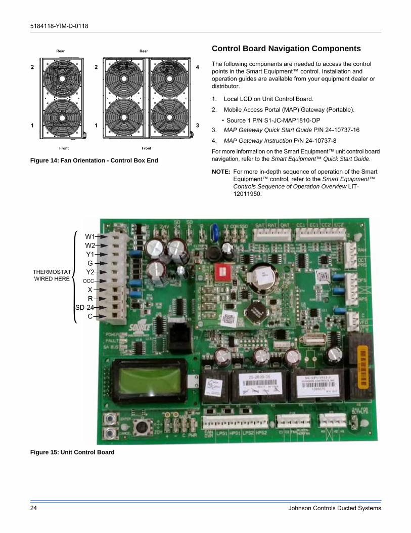
Figure 14: Fan Orientation - Control Box End
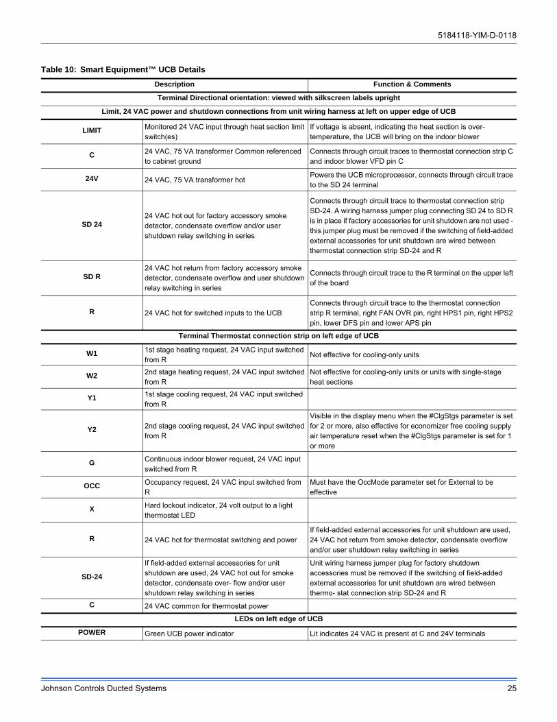
Control Board Navigation Components
The following components are needed to access the control points in the Smart Equipment™ control. Installation and operation guides are available from your equipment dealer or distributor.
1. Local LCD on Unit Control Board.
2. Mobile Access Portal (MAP) Gateway (Portable).
• Source 1 P/N S1-JC-MAP1810-OP
3. MAP Gateway Quick Start Guide P/N 24-10737-16
4. MAP Gateway Instruction P/N 24-10737-8
For more information on the Smart Equipment™ unit control board navigation, refer to the Smart Equipment™ Quick Start Guide.
NOTE: For more in-depth sequence of operation of the Smart Equipment™ control, refer to the Smart Equipment™ Controls Sequence of Operation Overview LIT-12011950.
Figure 15: Unit Control Board
Rear
Front
Rear
Front
2
1
2
1
4
3
W1W2Y1GY2
OCC
CSD-24
THERMOSTATWIRED HERE R
X
5184118-YIM-D-0118
Johnson Controls Ducted Systems 25
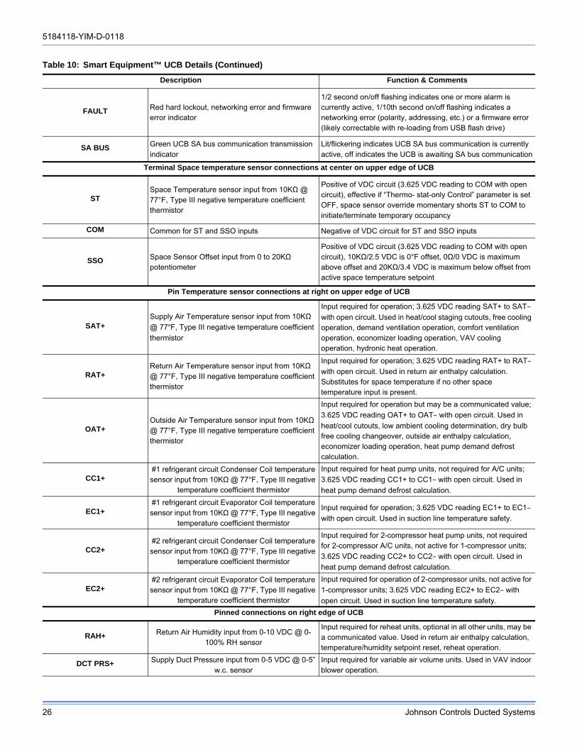
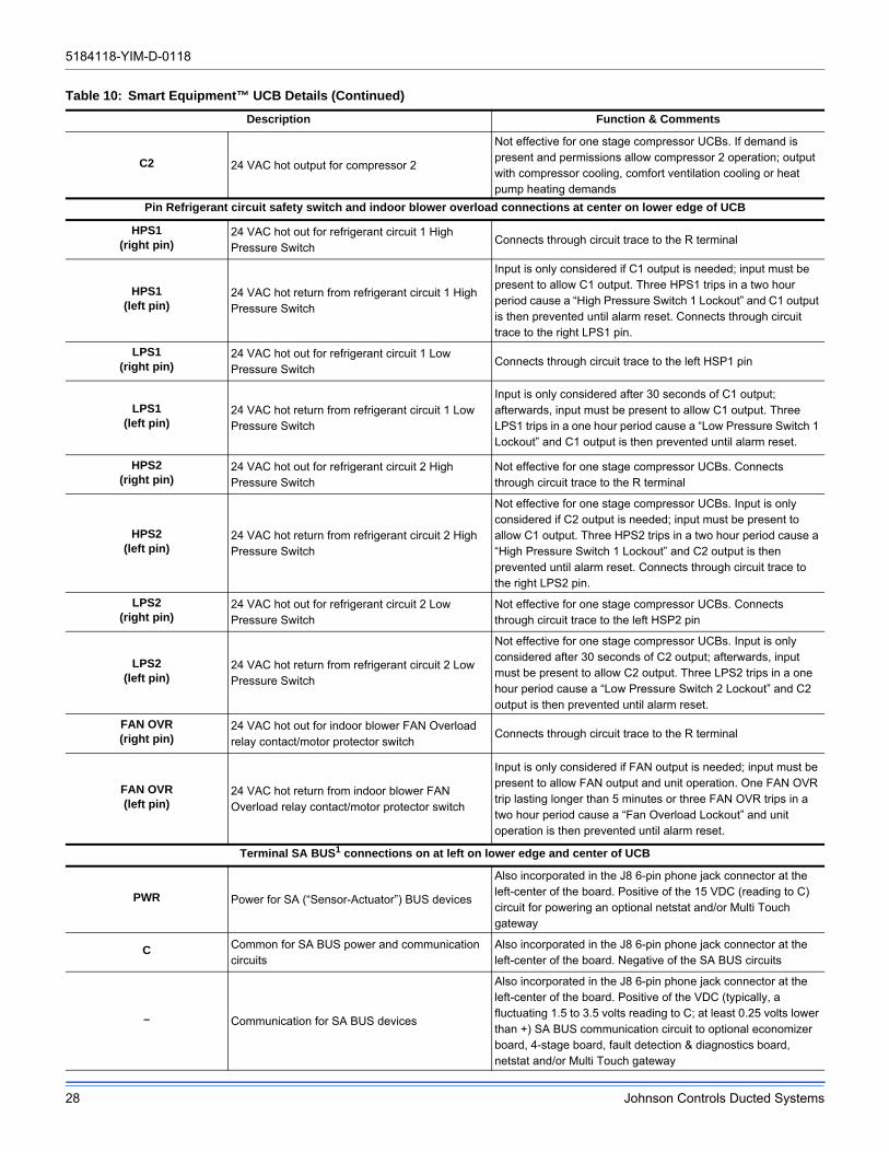
Table 10: Smart Equipment™ UCB Details
Description Function & Comments
Terminal Directional orientation: viewed with silkscreen labels upright
Limit, 24 VAC power and shutdown connections from unit wiring harness at left on upper edge of UCB
LIMIT Monitored 24 VAC input through heat section limit switch(es)
If voltage is absent, indicating the heat section is over-temperature, the UCB will bring on the indoor blower
C 24 VAC, 75 VA transformer Common referenced to cabinet ground
Connects through circuit traces to thermostat connection strip C and indoor blower VFD pin C
24V 24 VAC, 75 VA transformer hotPowers the UCB microprocessor, connects through circuit trace to the SD 24 terminal
SD 2424 VAC hot out for factory accessory smoke detector, condensate overflow and/or user shutdown relay switching in series
Connects through circuit trace to thermostat connection strip SD-24. A wiring harness jumper plug connecting SD 24 to SD R is in place if factory accessories for unit shutdown are not used - this jumper plug must be removed if the switching of field-added external accessories for unit shutdown are wired between thermostat connection strip SD-24 and R
SD R24 VAC hot return from factory accessory smoke detector, condensate overflow and user shutdown relay switching in series
Connects through circuit trace to the R terminal on the upper left of the board
R 24 VAC hot for switched inputs to the UCBConnects through circuit trace to the thermostat connection strip R terminal, right FAN OVR pin, right HPS1 pin, right HPS2 pin, lower DFS pin and lower APS pin
Terminal Thermostat connection strip on left edge of UCB
W1 1st stage heating request, 24 VAC input switched from R
Not effective for cooling-only units
W2 2nd stage heating request, 24 VAC input switched from R
Not effective for cooling-only units or units with single-stage heat sections
Y1 1st stage cooling request, 24 VAC input switched from R
Y2 2nd stage cooling request, 24 VAC input switched from R
Visible in the display menu when the #ClgStgs parameter is set for 2 or more, also effective for economizer free cooling supply air temperature reset when the #ClgStgs parameter is set for 1 or more
G Continuous indoor blower request, 24 VAC input switched from R
OCC Occupancy request, 24 VAC input switched from R
Must have the OccMode parameter set for External to be effective
X Hard lockout indicator, 24 volt output to a light thermostat LED
R 24 VAC hot for thermostat switching and powerIf field-added external accessories for unit shutdown are used, 24 VAC hot return from smoke detector, condensate overflow and/or user shutdown relay switching in series
SD-24
If field-added external accessories for unit shutdown are used, 24 VAC hot out for smoke detector, condensate over- flow and/or user shutdown relay switching in series
Unit wiring harness jumper plug for factory shutdown accessories must be removed if the switching of field-added external accessories for unit shutdown are wired between thermo- stat connection strip SD-24 and R
C 24 VAC common for thermostat power
LEDs on left edge of UCB
POWER Green UCB power indicator Lit indicates 24 VAC is present at C and 24V terminals
5184118-YIM-D-0118
26 Johnson Controls Ducted Systems
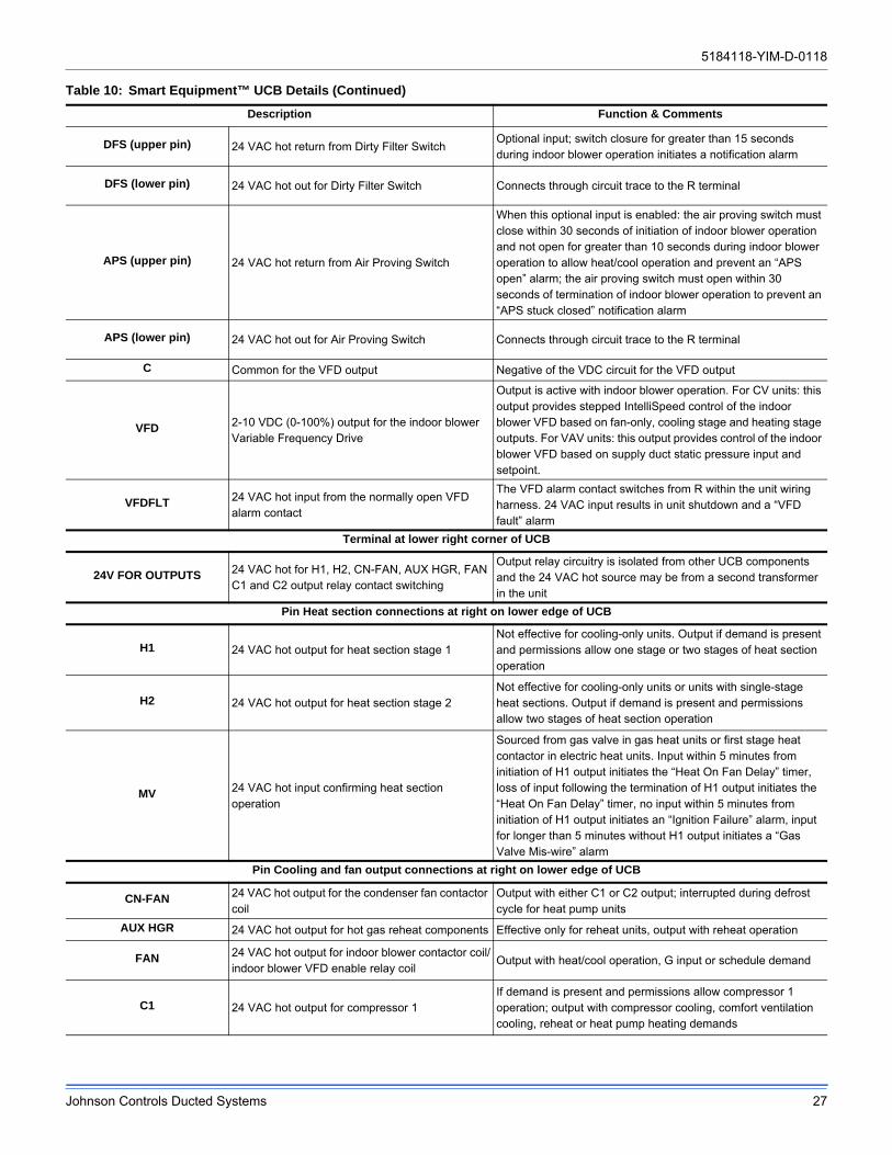
FAULT Red hard lockout, networking error and firmware error indicator
1/2 second on/off flashing indicates one or more alarm is currently active, 1/10th second on/off flashing indicates a networking error (polarity, addressing, etc.) or a firmware error (likely correctable with re-loading from USB flash drive)
SA BUS Green UCB SA bus communication transmission indicator
Lit/flickering indicates UCB SA bus communication is currently active, off indicates the UCB is awaiting SA bus communication
Terminal Space temperature sensor connections at center on upper edge of UCB
STSpace Temperature sensor input from 10KΩ @ 77°F, Type III negative temperature coefficient thermistor
Positive of VDC circuit (3.625 VDC reading to COM with open circuit), effective if “Thermo- stat-only Control” parameter is set OFF, space sensor override momentary shorts ST to COM to initiate/terminate temporary occupancy
COM Common for ST and SSO inputs Negative of VDC circuit for ST and SSO inputs
SSO Space Sensor Offset input from 0 to 20KΩ potentiometer
Positive of VDC circuit (3.625 VDC reading to COM with open circuit), 10KΩ/2.5 VDC is 0°F offset, 0Ω/0 VDC is maximum above offset and 20KΩ/3.4 VDC is maximum below offset from active space temperature setpoint
Pin Temperature sensor connections at right on upper edge of UCB
SAT+Supply Air Temperature sensor input from 10KΩ
@ 77°F, Type III negative temperature coefficient
thermistor
Input required for operation; 3.625 VDC reading SAT+ to SAT–
with open circuit. Used in heat/cool staging cutouts, free cooling operation, demand ventilation operation, comfort ventilation operation, economizer loading operation, VAV cooling operation, hydronic heat operation.
RAT+Return Air Temperature sensor input from 10KΩ @ 77°F, Type III negative temperature coefficient thermistor
Input required for operation; 3.625 VDC reading RAT+ to RAT–
with open circuit. Used in return air enthalpy calculation. Substitutes for space temperature if no other space temperature input is present.
OAT+Outside Air Temperature sensor input from 10KΩ @ 77°F, Type III negative temperature coefficient thermistor
Input required for operation but may be a communicated value;
3.625 VDC reading OAT+ to OAT– with open circuit. Used in
heat/cool cutouts, low ambient cooling determination, dry bulb free cooling changeover, outside air enthalpy calculation, economizer loading operation, heat pump demand defrost calculation.
CC1+#1 refrigerant circuit Condenser Coil temperature sensor input from 10KΩ @ 77°F, Type III negative
temperature coefficient thermistor
Input required for heat pump units, not required for A/C units;
3.625 VDC reading CC1+ to CC1– with open circuit. Used in
heat pump demand defrost calculation.
EC1+#1 refrigerant circuit Evaporator Coil temperature sensor input from 10KΩ @ 77°F, Type III negative
temperature coefficient thermistor
Input required for operation; 3.625 VDC reading EC1+ to EC1–
with open circuit. Used in suction line temperature safety.
CC2+#2 refrigerant circuit Condenser Coil temperature sensor input from 10KΩ @ 77°F, Type III negative
temperature coefficient thermistor
Input required for 2-compressor heat pump units, not required for 2-compressor A/C units, not active for 1-compressor units;
3.625 VDC reading CC2+ to CC2– with open circuit. Used in
heat pump demand defrost calculation.
EC2+#2 refrigerant circuit Evaporator Coil temperature sensor input from 10KΩ @ 77°F, Type III negative
temperature coefficient thermistor
Input required for operation of 2-compressor units, not active for
1-compressor units; 3.625 VDC reading EC2+ to EC2– with
open circuit. Used in suction line temperature safety.
Pinned connections on right edge of UCB
RAH+ Return Air Humidity input from 0-10 VDC @ 0-100% RH sensor
Input required for reheat units, optional in all other units, may be a communicated value. Used in return air enthalpy calculation, temperature/humidity setpoint reset, reheat operation.
DCT PRS+ Supply Duct Pressure input from 0-5 VDC @ 0-5” w.c. sensor
Input required for variable air volume units. Used in VAV indoor blower operation.
Table 10: Smart Equipment™ UCB Details (Continued)
Description Function & Comments
5184118-YIM-D-0118
Johnson Controls Ducted Systems 27
DFS (upper pin) 24 VAC hot return from Dirty Filter SwitchOptional input; switch closure for greater than 15 seconds during indoor blower operation initiates a notification alarm
DFS (lower pin) 24 VAC hot out for Dirty Filter Switch Connects through circuit trace to the R terminal
APS (upper pin) 24 VAC hot return from Air Proving Switch
When this optional input is enabled: the air proving switch must close within 30 seconds of initiation of indoor blower operation and not open for greater than 10 seconds during indoor blower operation to allow heat/cool operation and prevent an “APS open” alarm; the air proving switch must open within 30 seconds of termination of indoor blower operation to prevent an “APS stuck closed” notification alarm
APS (lower pin) 24 VAC hot out for Air Proving Switch Connects through circuit trace to the R terminal
C Common for the VFD output Negative of the VDC circuit for the VFD output
VFD 2-10 VDC (0-100%) output for the indoor blower Variable Frequency Drive
Output is active with indoor blower operation. For CV units: this output provides stepped IntelliSpeed control of the indoor blower VFD based on fan-only, cooling stage and heating stage outputs. For VAV units: this output provides control of the indoor blower VFD based on supply duct static pressure input and setpoint.
VFDFLT 24 VAC hot input from the normally open VFD alarm contact
The VFD alarm contact switches from R within the unit wiring harness. 24 VAC input results in unit shutdown and a “VFD fault” alarm
Terminal at lower right corner of UCB
24V FOR OUTPUTS 24 VAC hot for H1, H2, CN-FAN, AUX HGR, FAN C1 and C2 output relay contact switching
Output relay circuitry is isolated from other UCB components and the 24 VAC hot source may be from a second transformer in the unit
Pin Heat section connections at right on lower edge of UCB
H1 24 VAC hot output for heat section stage 1Not effective for cooling-only units. Output if demand is present and permissions allow one stage or two stages of heat section operation
H2 24 VAC hot output for heat section stage 2Not effective for cooling-only units or units with single-stage heat sections. Output if demand is present and permissions allow two stages of heat section operation
MV 24 VAC hot input confirming heat section operation
Sourced from gas valve in gas heat units or first stage heat contactor in electric heat units. Input within 5 minutes from initiation of H1 output initiates the “Heat On Fan Delay” timer, loss of input following the termination of H1 output initiates the “Heat On Fan Delay” timer, no input within 5 minutes from initiation of H1 output initiates an “Ignition Failure” alarm, input for longer than 5 minutes without H1 output initiates a “Gas Valve Mis-wire” alarm
Pin Cooling and fan output connections at right on lower edge of UCB
CN-FAN 24 VAC hot output for the condenser fan contactor coil
Output with either C1 or C2 output; interrupted during defrost cycle for heat pump units
AUX HGR 24 VAC hot output for hot gas reheat components Effective only for reheat units, output with reheat operation
FAN 24 VAC hot output for indoor blower contactor coil/indoor blower VFD enable relay coil
Output with heat/cool operation, G input or schedule demand
C1 24 VAC hot output for compressor 1If demand is present and permissions allow compressor 1 operation; output with compressor cooling, comfort ventilation cooling, reheat or heat pump heating demands
Table 10: Smart Equipment™ UCB Details (Continued)
Description Function & Comments
5184118-YIM-D-0118
28 Johnson Controls Ducted Systems
C2 24 VAC hot output for compressor 2
Not effective for one stage compressor UCBs. If demand is present and permissions allow compressor 2 operation; output with compressor cooling, comfort ventilation cooling or heat pump heating demands
Pin Refrigerant circuit safety switch and indoor blower overload connections at center on lower edge of UCB
HPS1(right pin)
24 VAC hot out for refrigerant circuit 1 High Pressure Switch
Connects through circuit trace to the R terminal
HPS1(left pin)
24 VAC hot return from refrigerant circuit 1 High Pressure Switch
Input is only considered if C1 output is needed; input must be present to allow C1 output. Three HPS1 trips in a two hour period cause a “High Pressure Switch 1 Lockout” and C1 output is then prevented until alarm reset. Connects through circuit trace to the right LPS1 pin.
LPS1(right pin)
24 VAC hot out for refrigerant circuit 1 Low Pressure Switch
Connects through circuit trace to the left HSP1 pin
LPS1(left pin)
24 VAC hot return from refrigerant circuit 1 Low Pressure Switch
Input is only considered after 30 seconds of C1 output; afterwards, input must be present to allow C1 output. Three LPS1 trips in a one hour period cause a “Low Pressure Switch 1 Lockout” and C1 output is then prevented until alarm reset.
HPS2(right pin)
24 VAC hot out for refrigerant circuit 2 High Pressure Switch
Not effective for one stage compressor UCBs. Connects through circuit trace to the R terminal
HPS2(left pin)
24 VAC hot return from refrigerant circuit 2 High Pressure Switch
Not effective for one stage compressor UCBs. Input is only considered if C2 output is needed; input must be present to allow C1 output. Three HPS2 trips in a two hour period cause a “High Pressure Switch 1 Lockout” and C2 output is then prevented until alarm reset. Connects through circuit trace to the right LPS2 pin.
LPS2(right pin)
24 VAC hot out for refrigerant circuit 2 Low Pressure Switch
Not effective for one stage compressor UCBs. Connects through circuit trace to the left HSP2 pin
LPS2(left pin)
24 VAC hot return from refrigerant circuit 2 Low Pressure Switch
Not effective for one stage compressor UCBs. Input is only considered after 30 seconds of C2 output; afterwards, input must be present to allow C2 output. Three LPS2 trips in a one hour period cause a “Low Pressure Switch 2 Lockout” and C2 output is then prevented until alarm reset.
FAN OVR(right pin)
24 VAC hot out for indoor blower FAN Overload relay contact/motor protector switch
Connects through circuit trace to the R terminal
FAN OVR(left pin)
24 VAC hot return from indoor blower FAN Overload relay contact/motor protector switch
Input is only considered if FAN output is needed; input must be present to allow FAN output and unit operation. One FAN OVR trip lasting longer than 5 minutes or three FAN OVR trips in a two hour period cause a “Fan Overload Lockout” and unit operation is then prevented until alarm reset.
Terminal SA BUS1 connections on at left on lower edge and center of UCB
PWR Power for SA (“Sensor-Actuator”) BUS devices
Also incorporated in the J8 6-pin phone jack connector at the left-center of the board. Positive of the 15 VDC (reading to C) circuit for powering an optional netstat and/or Multi Touch gateway
C Common for SA BUS power and communication circuits
Also incorporated in the J8 6-pin phone jack connector at the left-center of the board. Negative of the SA BUS circuits
– Communication for SA BUS devices
Also incorporated in the J8 6-pin phone jack connector at the left-center of the board. Positive of the VDC (typically, a fluctuating 1.5 to 3.5 volts reading to C; at least 0.25 volts lower than +) SA BUS communication circuit to optional economizer board, 4-stage board, fault detection & diagnostics board, netstat and/or Multi Touch gateway
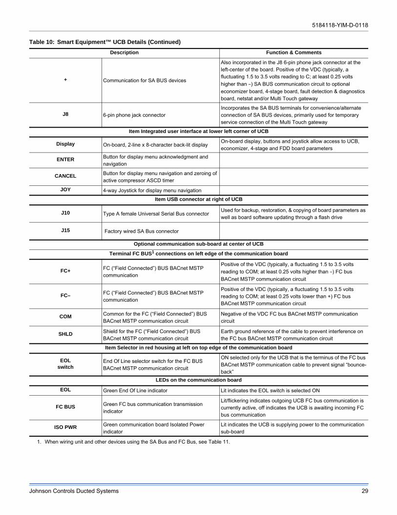
Table 10: Smart Equipment™ UCB Details (Continued)
Description Function & Comments
5184118-YIM-D-0118
Johnson Controls Ducted Systems 29
+ Communication for SA BUS devices
Also incorporated in the J8 6-pin phone jack connector at the left-center of the board. Positive of the VDC (typically, a fluctuating 1.5 to 3.5 volts reading to C; at least 0.25 volts
higher than –) SA BUS communication circuit to optional
economizer board, 4-stage board, fault detection & diagnostics board, netstat and/or Multi Touch gateway
J8 6-pin phone jack connectorIncorporates the SA BUS terminals for convenience/alternate connection of SA BUS devices, primarily used for temporary service connection of the Multi Touch gateway
Item Integrated user interface at lower left corner of UCB
Display On-board, 2-line x 8-character back-lit displayOn-board display, buttons and joystick allow access to UCB, economizer, 4-stage and FDD board parameters
ENTER Button for display menu acknowledgment and navigation
CANCEL Button for display menu navigation and zeroing of active compressor ASCD timer
JOY 4-way Joystick for display menu navigation
Item USB connector at right of UCB
J10 Type A female Universal Serial Bus connectorUsed for backup, restoration, & copying of board parameters as well as board software updating through a flash drive
J15 Factory wired SA Bus connector
Optional communication sub-board at center of UCB
Terminal FC BUS1 connections on left edge of the communication board
FC+ FC (“Field Connected”) BUS BACnet MSTP communication
Positive of the VDC (typically, a fluctuating 1.5 to 3.5 volts
reading to COM; at least 0.25 volts higher than –) FC bus
BACnet MSTP communication circuit
FC– FC (“Field Connected”) BUS BACnet MSTP communication
Positive of the VDC (typically, a fluctuating 1.5 to 3.5 volts reading to COM; at least 0.25 volts lower than +) FC bus BACnet MSTP communication circuit
COM Common for the FC (“Field Connected”) BUS BACnet MSTP communication circuit
Negative of the VDC FC bus BACnet MSTP communication circuit
SHLD Shield for the FC (“Field Connected”) BUS BACnet MSTP communication circuit
Earth ground reference of the cable to prevent interference on the FC bus BACnet MSTP communication circuit
Item Selector in red housing at left on top edge of the communication board
EOLswitch
End Of Line selector switch for the FC BUS BACnet MSTP communication circuit
ON selected only for the UCB that is the terminus of the FC bus BACnet MSTP communication cable to prevent signal “bounce-back”
LEDs on the communication board
EOL Green End Of Line indicator Lit indicates the EOL switch is selected ON
FC BUS Green FC bus communication transmission indicator
Lit/flickering indicates outgoing UCB FC bus communication is currently active, off indicates the UCB is awaiting incoming FC bus communication
ISO PWR Green communication board Isolated Power indicator
Lit indicates the UCB is supplying power to the communication sub-board
1. When wiring unit and other devices using the SA Bus and FC Bus, see Table 11.
Table 10: Smart Equipment™ UCB Details (Continued)
Description Function & Comments
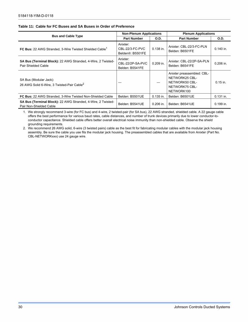
5184118-YIM-D-0118
30 Johnson Controls Ducted Systems
Table 11: Cable for FC Buses and SA Buses in Order of Preference
Bus and Cable TypeNon-Plenum Applications Plenum Applications
Part Number O.D. Part Number O.D.
FC Bus: 22 AWG Stranded, 3-Wire Twisted Shielded Cable1Anixter:CBL-22/3-FC-PVCBelden®: B5501FE
0.138 in.Anixter: CBL-22/3-FC-PLN Belden: B6501FE
0.140 in.
SA Bus (Terminal Block): 22 AWG Stranded, 4-Wire, 2 Twisted-Pair Shielded Cable
Anixter:CBL-22/2P-SA-PVCBelden: B5541FE
0.209 in.Anixter: CBL-22/2P-SA-PLNBelden: B6541FE
0.206 in.
SA Bus (Modular Jack):
26 AWG Solid 6-Wire, 3 Twisted-Pair Cable2 — —
Anixter preassembled: CBL-NETWORK25 CBL-NETWORK50 CBL-NETWORK75 CBL-NETWORK100
0.15 in.
FC Bus: 22 AWG Stranded, 3-Wire Twisted Non-Shielded Cable Belden: B5501UE 0.135 in. Belden: B6501UE 0.131 in.
SA Bus (Terminal Block): 22 AWG Stranded, 4-Wire, 2 Twisted-Pair Non-Shielded Cable
Belden: B5541UE 0.206 in. Belden: B6541UE 0.199 in.
1. We strongly recommend 3-wire (for FC bus) and 4-wire, 2 twisted-pair (for SA bus), 22 AWG stranded, shielded cable. A 22 gauge cable offers the best performance for various baud rates, cable distances, and number of trunk devices primarily due to lower conductor-to-conductor capacitance. Shielded cable offers better overall electrical noise immunity than non-shielded cable. Observe the shield grounding requirements.
2. We recommend 26 AWG solid, 6-wire (3 twisted pairs) cable as the best fit for fabricating modular cables with the modular jack housing assembly. Be sure the cable you use fits the modular jack housing. The preassembled cables that are available from Anixter (Part No. CBL-NETWORKxxx) use 24 gauge wire.
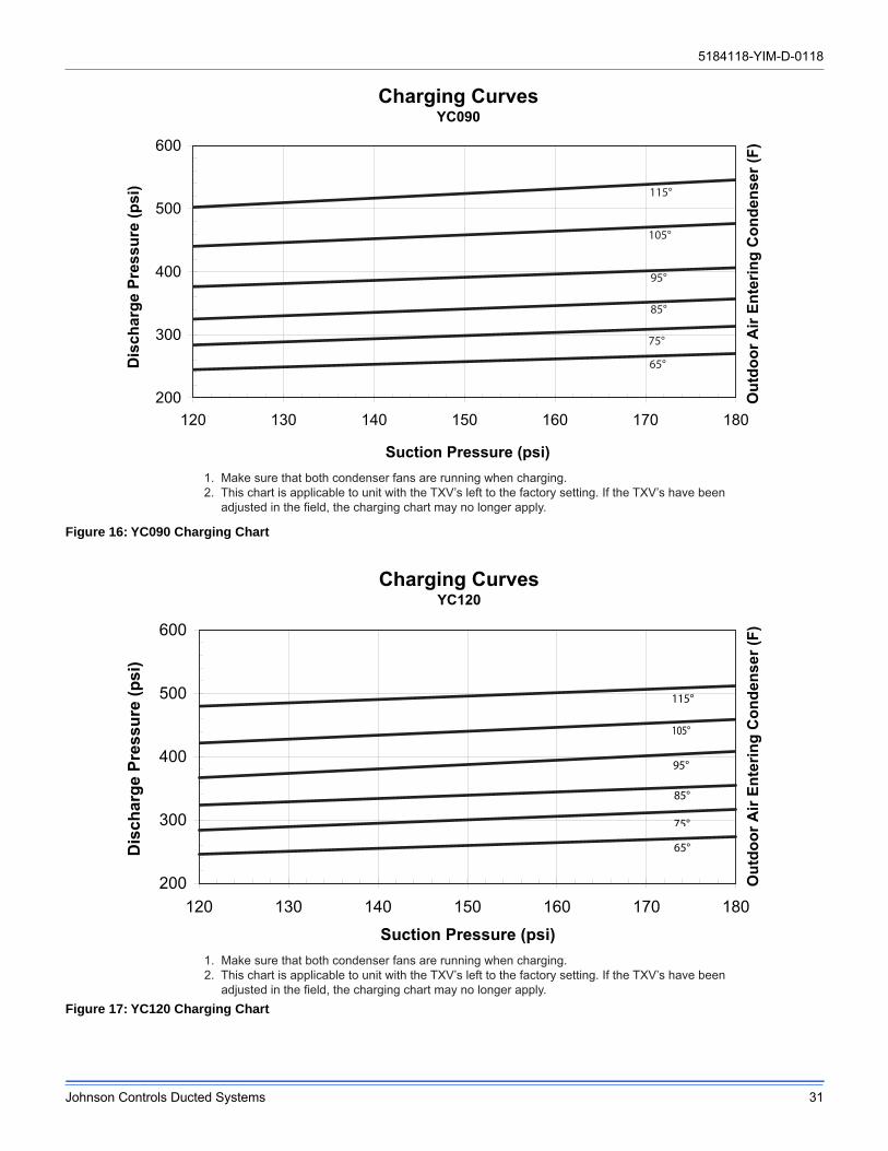
5184118-YIM-D-0118
Johnson Controls Ducted Systems 31
Figure 16: YC090 Charging Chart
Figure 17: YC120 Charging Chart
Charging CurvesYC090
200
300
400
500
600
120 130 140 150 160 170 180
Suction Pressure (psi)
Dis
char
ge P
ress
ure
(psi
) 115°
105°
95°
85°
75°
65°
Out
door
Air
Ente
ring
Con
dens
er (F
)
1. Make sure that both condenser fans are running when charging.2. This chart is applicable to unit with the TXV’s left to the factory setting. If the TXV’s have been adjusted in the field, the charging chart may no longer apply.
Charging CurvesYC120
200
300
400
500
600
120 130 140 150 160 170 180
Suction Pressure (psi)
Dis
char
ge P
ress
ure
(psi
)
115°
105°
95°
85°
65°
75°
Out
door
Air
Ente
ring
Con
dens
er (F
)
1. Make sure that both condenser fans are running when charging.2. This chart is applicable to unit with the TXV’s left to the factory setting. If the TXV’s have been adjusted in the field, the charging chart may no longer apply.
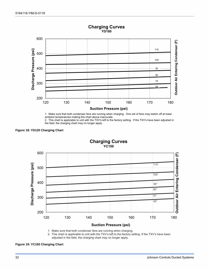
5184118-YIM-D-0118
32 Johnson Controls Ducted Systems
Figure 18: YD120 Charging Chart
Figure 19: YC150 Charging Chart
200
300
400
500
600
120 130 140 150 160 170 180
Dis
char
ge P
ress
ure
(psi
)
Suction Pressure (psi)
Charging CurvesYD180
115
105
95
85
75
65
1. Make sure that both condenser fans are running when charging. One set of fans may switch off at lowerambient temperatures making the chart above inaccurate.2. This chart is applicable to unit with the TXV's left to the factory setting. If the TXV's have been adjusted inthe field, the charging chart may no longer apply.
Out
door
Air
Ente
ring
Con
dens
er (F
)
Charging CurvesYC150
200
300
400
500
600
120 130 140 150 160 170 180
Suction Pressure (psi)
Dis
char
ge P
ress
ure
(psi
)
115°
105°
95°
85°
75°
65°
Out
door
Air
Ente
ring
Con
dens
er (F
)
1. Make sure that both condenser fans are running when charging.2. This chart is applicable to unit with the TXV’s left to the factory setting. If the TXV’s have been adjusted in the field, the charging chart may no longer apply.
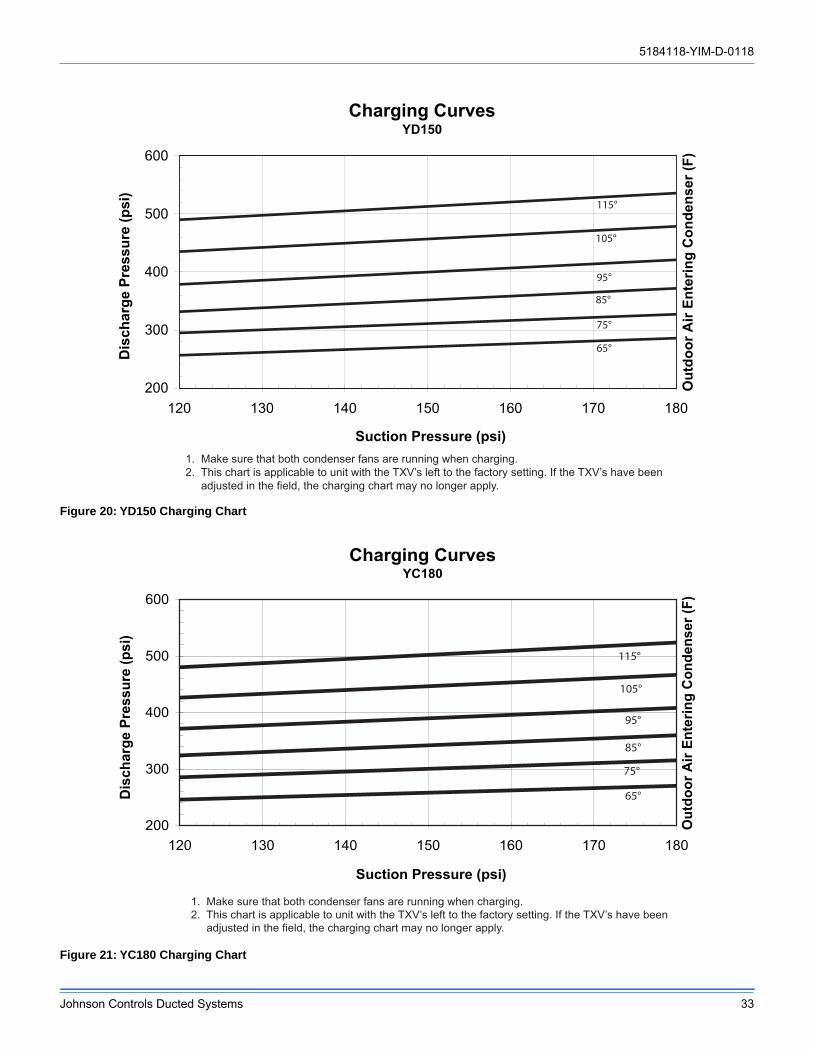
5184118-YIM-D-0118
Johnson Controls Ducted Systems 33
Figure 20: YD150 Charging Chart
Figure 21: YC180 Charging Chart
Charging CurvesYD150
200
300
400
500
600
120 130 140 150 160 170 180
Suction Pressure (psi)
Dis
char
ge P
ress
ure
(psi
)
115°
105°
95°
85°
75°
65°
Out
door
Air
Ente
ring
Con
dens
er (F
)
1. Make sure that both condenser fans are running when charging.2. This chart is applicable to unit with the TXV’s left to the factory setting. If the TXV’s have been adjusted in the field, the charging chart may no longer apply.
Charging CurvesYC180
200
300
400
500
600
120 130 140 150 160 170 180
Suction Pressure (psi)
Dis
char
ge P
ress
ure
(psi
)
1. Make sure that both condenser fans are running when charging.2. This chart is applicable to unit with the TXV’s left to the factory setting. If the TXV’s have been adjusted in the field, the charging chart may no longer apply.
Out
door
Air
Ente
ring
Con
dens
er (F
)
115°
95°
65°
75°
85°
105°
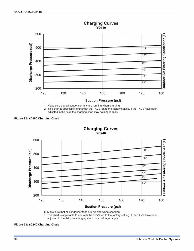
5184118-YIM-D-0118
34 Johnson Controls Ducted Systems
Figure 22: YD180 Charging Chart
Figure 23: YC240 Charging Chart
Charging CurvesYD180
200
300
400
500
600
120 130 140 150 160 170 180
Suction Pressure (psi)
Dis
char
ge P
ress
ure
(psi
)
115°
105°
95°
85°
75°
65°
Out
door
Air
Ente
ring
Con
dens
er (F
)
1. Make sure that all condenser fans are running when charging.2. This chart is applicable to unit with the TXV’s left to the factory setting. If the TXV’s have been
adjusted in the field, the charging chart may no longer apply.
Charging CurvesYC240
200
300
400
500
600
120 130 140 150 160 170 180
Suction Pressure (psi)
Dis
char
ge P
ress
ure
(psi
) 115°
105°
95°
85°
75°
65°
Out
door
Air
Ente
ring
Con
dens
er (F
)
1. Make sure that all condenser fans are running when charging.2. This chart is applicable to unit with the TXV’s left to the factory setting. If the TXV’s have been adjusted in the field, the charging chart may no longer apply.
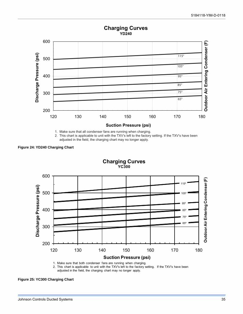
5184118-YIM-D-0118
Johnson Controls Ducted Systems 35
Figure 24: YD240 Charging Chart
Figure 25: YC300 Charging Chart
Charging CurvesYD240
200
300
400
500
600
120 130 140 150 160 170 180
Suction Pressure (psi)
Dis
char
ge P
ress
ure
(psi
)
115°
105°
95°
85°
75°
65°
Out
door
Air
Ente
ring
Con
dens
er (F
)
1. Make sure that all condenser fans are running when charging.2. This chart is applicable to unit with the TXV’s left to the factory setting. If the TXV’s have been adjusted in the field, the charging chart may no longer apply.
200
300
400
500
600
120 130 140 150 160 170 180
Dis
char
ge P
ress
ure
(psi
)
Suction Pressure (psi)
Charging CurvesYC300
115º
105º
95º
85º
75º
65º
1. Make sure that both condenser fans are running when charging.2. This chart is applicable to unit with the TXV's left to the factory setting. If the TXV's have been
adjusted in the field, the charging chart may no longer apply.
Out
door
Air
Ente
ring
Con
dens
er (F
)
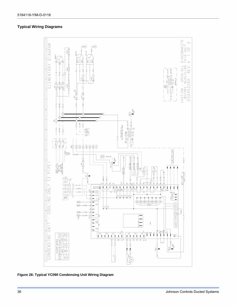
5184118-YIM-D-0118
36 Johnson Controls Ducted Systems
Typical Wiring Diagrams
Figure 26: Typical YC090 Condensing Unit Wiring Diagram
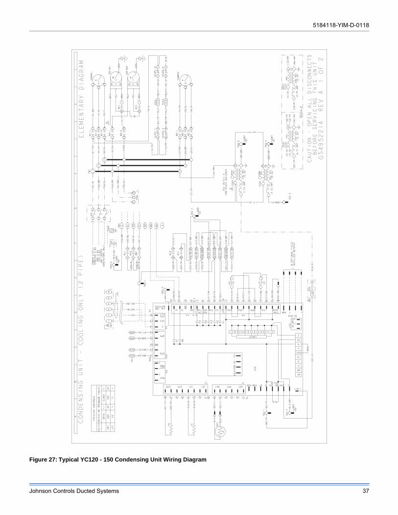
5184118-YIM-D-0118
Johnson Controls Ducted Systems 37
Figure 27: Typical YC120 - 150 Condensing Unit Wiring Diagram
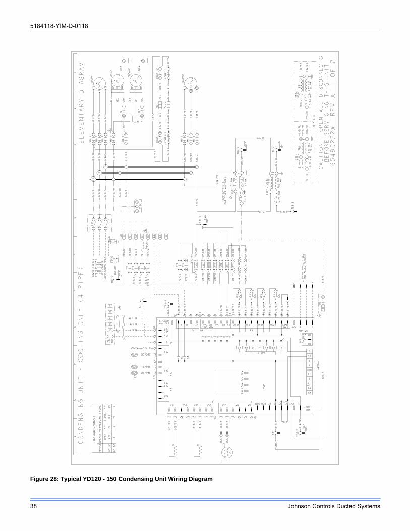
5184118-YIM-D-0118
38 Johnson Controls Ducted Systems
Figure 28: Typical YD120 - 150 Condensing Unit Wiring Diagram
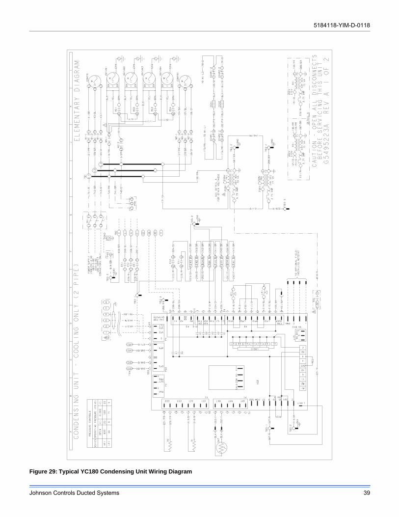
5184118-YIM-D-0118
Johnson Controls Ducted Systems 39
Figure 29: Typical YC180 Condensing Unit Wiring Diagram
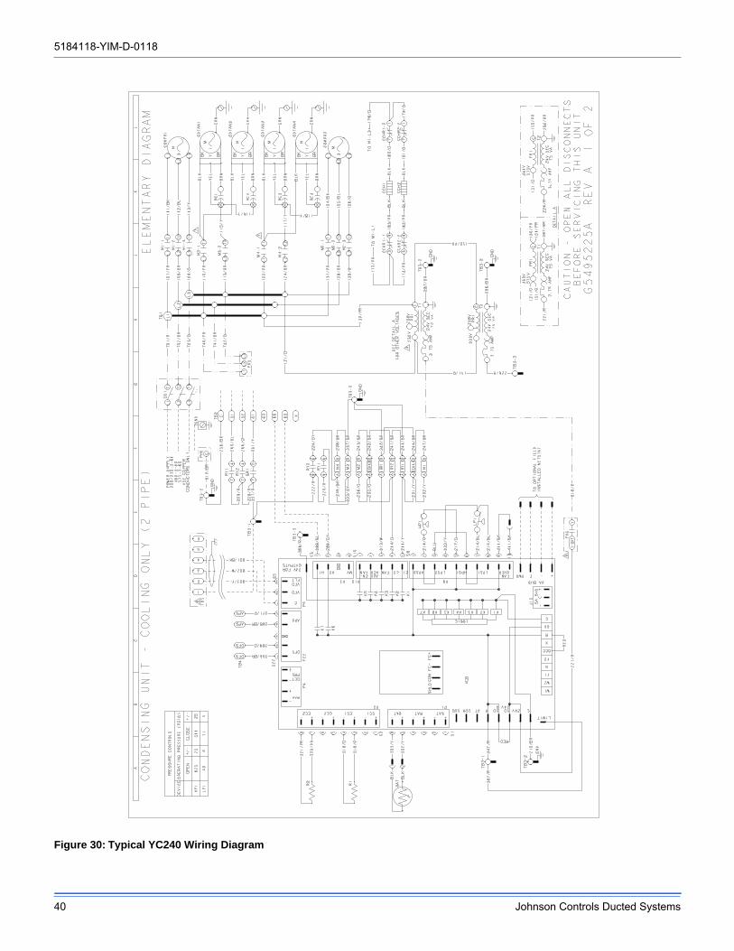
5184118-YIM-D-0118
40 Johnson Controls Ducted Systems
Figure 30: Typical YC240 Wiring Diagram
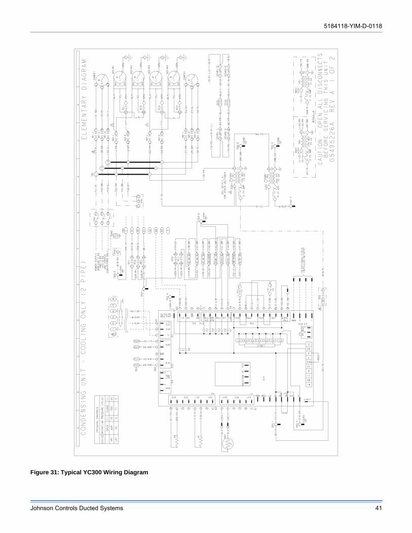
5184118-YIM-D-0118
Johnson Controls Ducted Systems 41
Figure 31: Typical YC300 Wiring Diagram
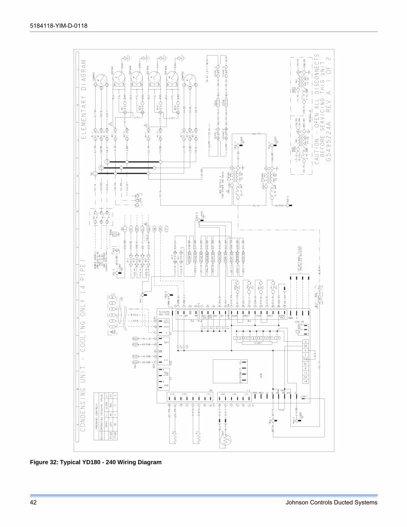
5184118-YIM-D-0118
42 Johnson Controls Ducted Systems
Figure 32: Typical YD180 - 240 Wiring Diagram
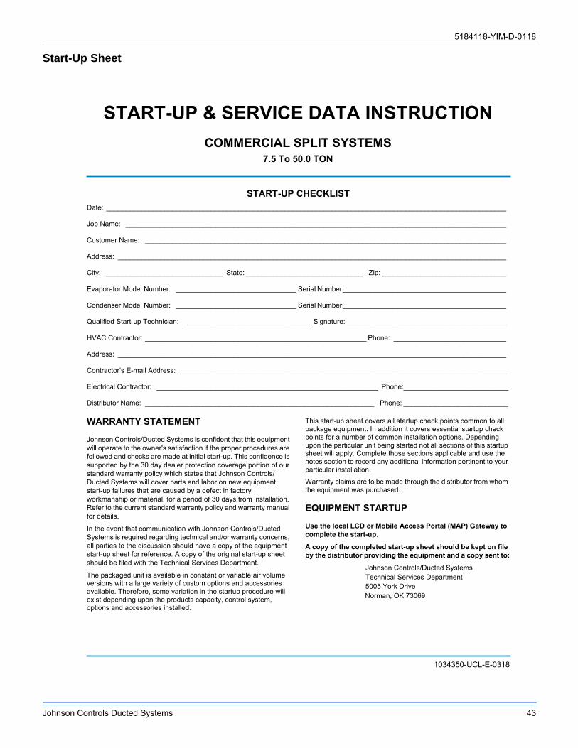
5184118-YIM-D-0118
Johnson Controls Ducted Systems 43
Start-Up Sheet
5184118-YIM-D-0118
44 Johnson Controls Ducted Systems
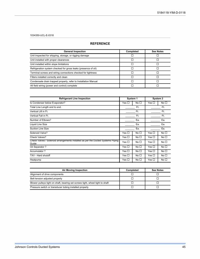
5184118-YIM-D-0118
Johnson Controls Ducted Systems 45
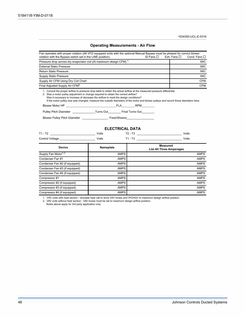
5184118-YIM-D-0118
46 Johnson Controls Ducted Systems
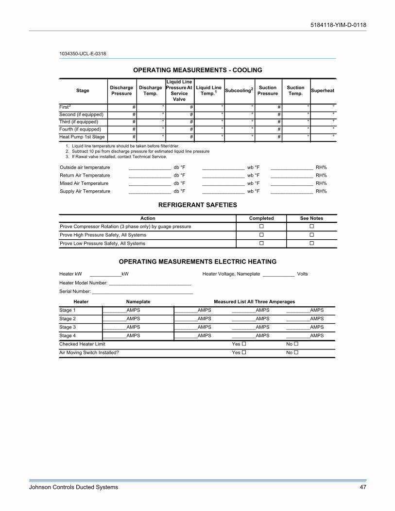
5184118-YIM-D-0118
Johnson Controls Ducted Systems 47
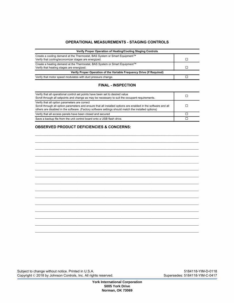
Subject to change without notice. Printed in U.S.A. 5184118-YIM-D-0118Copyright © 2018 by Johnson Controls, Inc. All rights reserved. Supersedes: 5184118-YIM-C-0417
York International Corporation5005 York Drive
Norman, OK 73069


![PACKAGEHEATPUMPSFEATURING INDUSTRYSTANDARDR-410A … · 2019. 4. 11. · []indicatesmetricconversion installationinstructions packageheatpumpsfeaturing industrystandardr-410a refrigerant](https://img.pdfslide.us/doc/110x75/5ff73f17096e4b21c6037881/packageheatpumpsfeaturing-industrystandardr-410a-2019-4-11-indicatesmetricconversion.jpg)