Embed Size (px)
Citation preview
3
Reference
Introduction
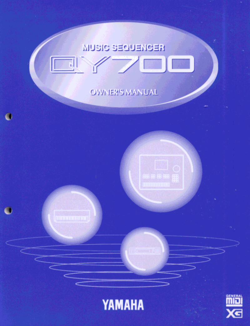
Thank you for purchasing the Yamaha QY700 music sequencer.
The QY700 is a 20 song / 32 track sequencer with 1/480th quarter note resolution featuring a built-in XG- and GM-compatible high-quality AWM2 tone generator, all contained in a newly-designed package. The Style Sequencer functions that were so popular on theQY300 etc. have been enhanced and made easier to use. A large LCD display also makes operation easier and more intuitive.
In order to take full advantage of the QY700’s functionality, please make good use of this owner’s manual. Once you have read it, keep itin a safe and convenient place for reference should any questions arise later.
Owner’s Manual
4
Features of the QY700
Features of the QY700
Powerful sequencer functionality
The sequencer of the QY700 provides 32 sequence tracks and 16 pattern tracks, and up to 110,000 notes of storagecapacity for professional-level sequencing power. Note timing resolution is 1/480th of a quarter note. Memory isbacked up, so your data will not disappear when the power is turned off. Play Effect functions and a full complementof editing jobs allow you to edit and modify your data as desired. Play Effects provide a Groove Quantize function thatlets you instantly produce a variety of different groove feelings. Also provided are jobs such as Chord Sort and ChordSeparate, convenient for entering guitar strokes.
Functional music production environment with Songs, Patterns, and Phrases
The QY700’s Auto-Accompaniment functionality provides a highly practical music production environment that letsyou use patterns and phrases to create your song.
Easy operation with large display, dials, function buttons, and direct buttons
The large 320 × 240 dot full-graphic display provides you with plenty of information for efficient music-making. Forexample, playback data can be viewed not only as an event list, but also graphically in a track-view or piano-rolldisplay.The jog dial provides an easy way to modify data, and the shuttle dial lets you rewind/fast-forward intuitively throughdata just as on a VTR.
Full assortment of preset phrases
The QY700 provides a vast 3,876 types of preset phrases from all musical genres. All preset phrases have been care-fully selected for immediate musical usefulness. Simply by combining preset phrases into patterns, you can createbacking data with infinite variety.
Undo/redo functionThe QY700 provides an Undo/Redo job. Even if recording, editing, or job execution has caused your important data todisappear, you will always be able to recover it.
5
Features of the QY700
XG tone generator for rich expressiveness
The QY700 features an XG-compatible tone generator with 491 high-quality voices and 3 high-quality effect systems,providing the rich expressiveness that you expect from XG.
Wide range of compatibility
The QY700’s tone generator section is compatible with XG and with the GM system level 1 tone generator format. Thesequencer section is compatible with ESEQ and SMF (Standard MIDI File) formats 0/1. Playback data that wascreated on the QS300 music synthesizer can also be played back on the QY700. You can also playback commerciallyavailable “XG-compatible song data” for additional enjoyment.
GM System Level 1“GM System Level 1” is a standard specification that defines the arrangement of voices in a tone generator and itsMIDI functionality, ensuring that data can be played back with substantially the same sounds on any GM-compatibletone generator, regardless of its manufacturer or model.Tone generators and song data that meet the “GM System Level 1” bear this GM logo.
XG“XG” is a tone generator format that expands the voice arrangement of the “GM System Level 1” specification to meetthe ever-increasing demands of today’s computer peripheral environment, providing richer expressive power whilemaintaining upward compatibility of data. “XG” greatly expands “GM System Level 1” by defining the ways in whichvoices are expanded or edited and the structure and type of effects.When commercially available song data bearing the XG logo is played back on a tone generator which bears the XGlogo, you will enjoy a full musical experience that includes unlimited expansion voices and effect functions.
6
How to use the manuals
How to use the manuals
The documentation for the QY700 consists of the following two manuals. Understand the role of each manual, and refer to them as necessary.
Owner’s Manual: Reference (this manual)
This explains precautions for use, how to make connections, and all parameters and commands. Use this manual like a dictionary wheneveryou need to.
Chapter 1. BASIC CONCEPTSChapter 2. SONG MODEChapter 3. VOICE MODEChapter 4. EFFECT MODEChapter 5. PATTERN MODEChapter 6. UTILITY MODEChapter 7. DISK MODE
“Song mode” and “Pattern mode” have several functions in common.In this manual, explanations for these common functions is given in greatest detail in chapter 2 “SONG MODE”. Some of the overlappingexplanation in chapter 5 “PATTERN MODE” is omitted. In such cases, the appropriate page of chapter 2 “SONG MODE” is indicated so thatyou can refer to it.
Owner’s Manual: QY700 Reference Listings
This is a booklet that contains various lists such as the Voice list, Preset Phrase list, Effect list, Chord Type list, MIDI data format, and MIDIimplementation chart.
Printing conventions in this manual
This manual uses the following icons to indicate buttons and to distinguish different types of information.
s This indicates a panel button. The characters in the box indicate the characters printed on the panel. Buttons for which there are nocharacters printed on the panel are indicated by the symbol printed on the panel, such as l. In the case of the function buttons 1
– 6, the function corresponding to each button is also given; for example, 3 (Effect).
[Explanation]This icon indicates an explanation of the function.
01011101
[Setting values]This icon indicates the range of values that can be set for that function.
7
[Procedure]This icon indicates the actual procedure for using the function.
[Supplementary comments]This icon indicates supplementary explanations related to the function, examples of use, and hints.
[Caution]This icon indicates a caution. To avoid erasing or damaging important data, be sure to read such sections.
+ This icon means that an operation needs to be performed while doing something else. For example, s + y means “hold downs and press y”.
/ This icon means “or”. For example,n/ymeans that you should press either thenor theykey.
→ This icon indicates the sequence in which buttons must be pressed. For example, numeric keys → e means that you must use thenumeric keys to select a value and then press the e button.
▼ This icon indicates the result of an operation.
→ p.● ● This indicates the page on which a related function or item is explained. Refer to these pages as necessary.
Printing conventions in this manual
8
Finding the information that you need
Finding the information that you need
In order to find the information that you need, you can make use of the following pages.
Table of contents ( → p.9)
Locate the desired information within the flow of the entire manual.
Front and rear panels ( → p.12)
Here you can read about the name and location of each button and control, and read about their function.
Function tree ( → p.34)
This lets you locate the desired information within the structure of the command hierarchy.
Glossary ( → p.324)
This section contains unfamiliar terms or phrases in alphabetical order with their explanations.
Index ( → p.328)
This lets you search alphabetically for unfamiliar terms to find pages on which they are discussed and pages on which related topics appear.
9
Table of contents
Table of contents
IntroductionFeatures of the QY700 ........................................................................................................................................................................................ 4How to use the manuals ...................................................................................................................................................................................... 6Printing conventions in this manual ................................................................................................................................................................... 6Finding the information that you need ............................................................................................................................................................... 8
SETUP1. Front and rear panels ................................................................................................................................................................................... 12
Top panel ................................................................................................................................................................................ 12Rear panel .............................................................................................................................................................................. 16Floppy disk drive ................................................................................................................................................................... 17
2. Connections ................................................................................................................................................................................................. 18Power supply connections...................................................................................................................................................... 18Audio equipment connections ............................................................................................................................................... 19Connecting a foot switch ....................................................................................................................................................... 20Connecting external MIDI devices ........................................................................................................................................ 20Connecting an MTR (multi-track recorder) ........................................................................................................................... 21Connecting two or more devices ............................................................................................................................................ 21
3. Using the Style and Demonstration disk ..................................................................................................................................................... 22Contents of the disk ............................................................................................................................................................... 22Listening to the demo playback ............................................................................................................................................. 22Restoring the factory settings ................................................................................................................................................ 23
Chapter 1. BASIC CONCEPTS1. Mode structure ............................................................................................................................................................................................ 262. Function tree................................................................................................................................................................................................ 343. How the QY700 is organized ...................................................................................................................................................................... 364. Sequencer block .......................................................................................................................................................................................... 375. The tone generator block ............................................................................................................................................................................. 436. Controller block .......................................................................................................................................................................................... 467. Effect block ................................................................................................................................................................................................. 478. Basic operation ............................................................................................................................................................................................ 519. Song creation procedure .............................................................................................................................................................................. 56
Create pattrens ....................................................................................................................................................................... 57Editing a pattern ..................................................................................................................................................................... 59Pattern track recording ........................................................................................................................................................... 60Chord track recording ............................................................................................................................................................ 61Voice settings ......................................................................................................................................................................... 62Realtime record of track 2 ..................................................................................................................................................... 62Step recording of track 1 ........................................................................................................................................................ 63Editing tracks 1 and 2 ............................................................................................................................................................ 65Modifying the voice of track 1 .............................................................................................................................................. 66Save to floppy disk ................................................................................................................................................................. 67
Chapter 2. SONG MODESONG MODE Overview .................................................................................................................................................................................. 701. SONG PLAY ............................................................................................................................................................................................... 722. Play Effects .................................................................................................................................................................................................. 80
Groove Quantizing ................................................................................................................................................................. 82Clock Shift, Gate Time, and Velocity .................................................................................................................................... 90Transposition .......................................................................................................................................................................... 94Drum Table Edit ..................................................................................................................................................................... 97
3. Track View ................................................................................................................................................................................................ 1004. Output Channels ........................................................................................................................................................................................ 103

10
Table of contents
5. Song Recording ......................................................................................................................................................................................... 106Recording Standby ............................................................................................................................................................... 108Realtime Recording: Sequence Tracks (TR1,...,TR32) ....................................................................................................... 112Realtime Recording: PATTERN Track................................................................................................................................ 113Realtime Recording: CHORD Track ................................................................................................................................... 115Realtime Recording: TEMPO Track .................................................................................................................................... 117Punch Recording .................................................................................................................................................................. 118Step Recording: Sequence Tracks (TR1,...,TR32) ............................................................................................................... 120Step Recording: PATTERN track ........................................................................................................................................ 125Step Recording: CHORD track ............................................................................................................................................ 127
6. Song Editing .............................................................................................................................................................................................. 1291 (Graphic) Graphic screen ....................................................................................................................................... 135
7. Song Jobs .................................................................................................................................................................................................. 138
Chapter 3. VOICE MODEAbout voice mode ........................................................................................................................................................................................... 1681. Mixer ......................................................................................................................................................................................................... 1702. Tune ........................................................................................................................................................................................................... 1743. Voice edit ................................................................................................................................................................................................... 1764. Drum Setup Edit ........................................................................................................................................................................................ 182
Chapter 4. EFFECT MODEAbout effect mode .......................................................................................................................................................................................... 1881. Connection ................................................................................................................................................................................................ 1902. Reverb edit, Chorus edit, Variation edit .................................................................................................................................................... 193
Chapter 5. PATTERN MODEPATTERN MODE Overview.......................................................................................................................................................................... 1981. PATCH ...................................................................................................................................................................................................... 200
Phrase Table ......................................................................................................................................................................... 2092. Play Effects ............................................................................................................................................................................................... 212
Groove Quantizing ............................................................................................................................................................... 214Clock Shift, Gate Time, and Velocity .................................................................................................................................. 217Transposition ........................................................................................................................................................................ 219Drum Table Edit ................................................................................................................................................................... 222
3. Pattern Voice submode .............................................................................................................................................................................. 225Mixer .................................................................................................................................................................................... 227Voice Edit ............................................................................................................................................................................. 232Drum-Setup Edit .................................................................................................................................................................. 235
4. Pattern Effects ........................................................................................................................................................................................... 239Connection ........................................................................................................................................................................... 241Reverb Edit, Chorus Edit, and Variation Edit ...................................................................................................................... 244
5. Phrase Recording ...................................................................................................................................................................................... 247Recording Standby ............................................................................................................................................................... 248Realtime Recording ............................................................................................................................................................. 252Step Recording ..................................................................................................................................................................... 253
6. Phrase Editing ........................................................................................................................................................................................... 2547. Pattern Jobs ............................................................................................................................................................................................... 256
Chapter 6. UTILITY MODEAbout Utility mode ......................................................................................................................................................................................... 2881. System ....................................................................................................................................................................................................... 2892. MIDI .......................................................................................................................................................................................................... 2913. MIDI filter ................................................................................................................................................................................................. 2934. Sequencer .................................................................................................................................................................................................. 2955. Click .......................................................................................................................................................................................................... 2976. Fingered chord zone .................................................................................................................................................................................. 299
11
Table of contents
Chapter 7. DISK MODEAbout floppy disks .......................................................................................................................................................................................... 302About Disk mode ............................................................................................................................................................................................ 3041. Save ........................................................................................................................................................................................................... 3072. Load........................................................................................................................................................................................................... 3103. Rename...................................................................................................................................................................................................... 3124. Delete ........................................................................................................................................................................................................ 3145. Format ....................................................................................................................................................................................................... 316
APPENDIX1. Specifications ............................................................................................................................................................................................ 3182. Troubleshooting ........................................................................................................................................................................................ 3203. Error messages .......................................................................................................................................................................................... 3224. Glossary..................................................................................................................................................................................................... 3245. Index .......................................................................................................................................................................................................... 328
12
SETUP
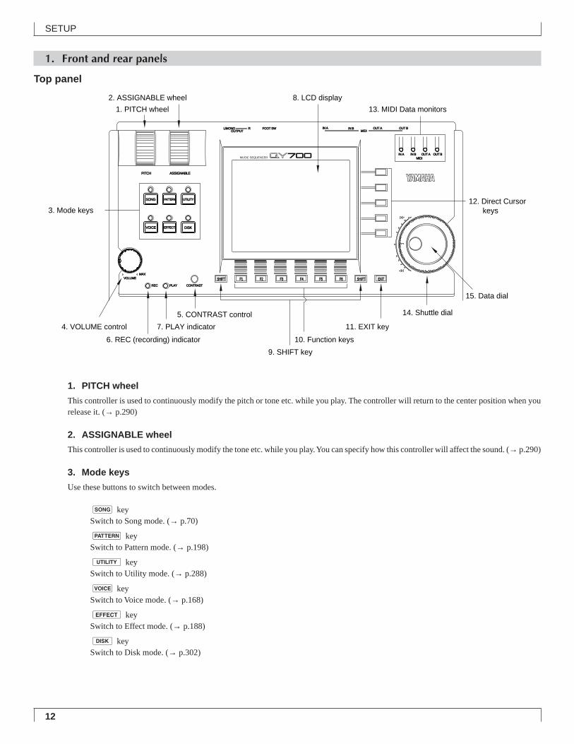
1. Front and rear panels
Top panel
1. PITCH wheel
This controller is used to continuously modify the pitch or tone etc. while you play. The controller will return to the center position when yourelease it. (→ p.290)
2. ASSIGNABLE wheel
This controller is used to continuously modify the tone etc. while you play. You can specify how this controller will affect the sound. (→ p.290)
3. Mode keys
Use these buttons to switch between modes.
s keySwitch to Song mode. (→ p.70)
p keySwitch to Pattern mode. (→ p.198)
u keySwitch to Utility mode. (→ p.288)
v keySwitch to Voice mode. (→ p.168)
e keySwitch to Effect mode. (→ p.188)
d keySwitch to Disk mode. (→ p.302)
7. PLAY indicator
CONTRAST
OUT BOUT AIN B
IN B
MIDI
MIDIOUT BOUT A
IN A
IN A
PLAYREC
VOICE
SHIFT F1 F2 F3 F4 F5 F6 SHIFT EXITMAX
VOLUME
EFFECT DISK
SONG
PITCH ASSIGNABLE
PATTERN UTILITY
FOOT SWRL/MONOOUTPUT
MUSIC SEQUENCER
1. PITCH wheel 13. MIDI Data monitors
2. ASSIGNABLE wheel 8. LCD display
3. Mode keys
4. VOLUME control
5. CONTRAST control 14. Shuttle dial
15. Data dial
6. REC (recording) indicator
11. EXIT key
10. Function keys
9. SHIFT key
12. Direct Cursorkeys
13
SETUP
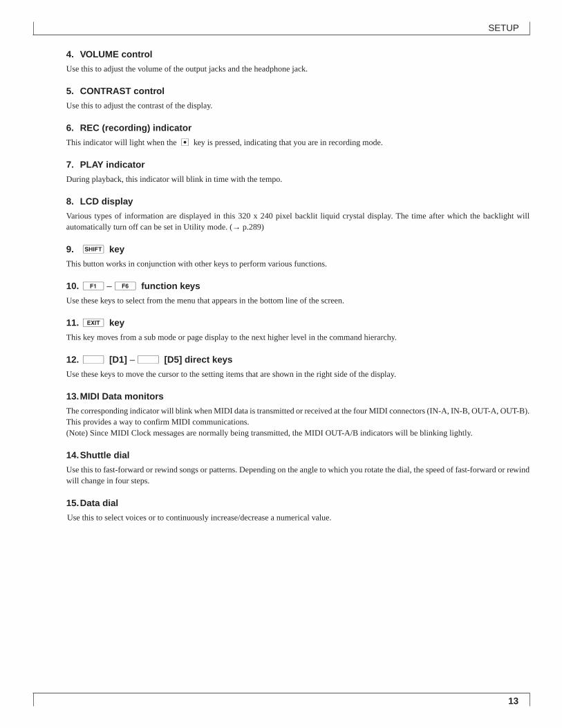
4. VOLUME control
Use this to adjust the volume of the output jacks and the headphone jack.
5. CONTRAST control
Use this to adjust the contrast of the display.
6. REC (recording) indicator
This indicator will light when the e key is pressed, indicating that you are in recording mode.
7. PLAY indicator
During playback, this indicator will blink in time with the tempo.
8. LCD display
Various types of information are displayed in this 320 x 240 pixel backlit liquid crystal display. The time after which the backlight willautomatically turn off can be set in Utility mode. (→ p.289)
9. s key
This button works in conjunction with other keys to perform various functions.
10.1–6 function keys
Use these keys to select from the menu that appears in the bottom line of the screen.
11.e key
This key moves from a sub mode or page display to the next higher level in the command hierarchy.
12.d [D1] –d [D5] direct keys
Use these keys to move the cursor to the setting items that are shown in the right side of the display.
13.MIDI Data monitors
The corresponding indicator will blink when MIDI data is transmitted or received at the four MIDI connectors (IN-A, IN-B, OUT-A, OUT-B).This provides a way to confirm MIDI communications.(Note) Since MIDI Clock messages are normally being transmitted, the MIDI OUT-A/B indicators will be blinking lightly.
14.Shuttle dial
Use this to fast-forward or rewind songs or patterns. Depending on the angle to which you rotate the dial, the speed of fast-forward or rewindwill change in four steps.
15.Data dial
Use this to select voices or to continuously increase/decrease a numerical value.
14
SETUP
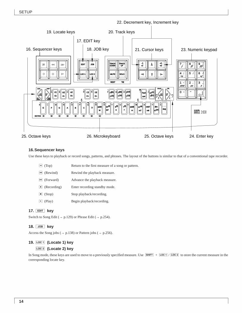
16.Sequencer keys
Use these keys to playback or record songs, patterns, and phrases. The layout of the buttons is similar to that of a conventional tape recorder.
t (Top) Return to the first measure of a song or pattern.
r (Rewind) Rewind the playback measure.
f (Forward) Advance the playback measure.
e (Recording) Enter recording standby mode.
s (Stop) Stop playback/recording.
p (Play) Begin playback/recording.
17.e key
Switch to Song Edit (→ p.129) or Phrase Edit (→ p.254).
18.j key
Access the Song jobs (→ p.138) or Pattern jobs (→ p.256).
19.1 (Locate 1) key
2 (Locate 2) key
In Song mode, these keys are used to move to a previously specified measure. Use s + 1/2 to store the current measure in thecorresponding locate key.
OCTDOWN
OCTUP
OCTDOWN
OCTUP
ONBASS
F #
E F G A B C DM
add9
M7
add9
a
m
mM7
m6
c
C # D #
REST
TRACKDOWN
TRACKUP
SOLOMUTE
EDIT JOB
LOC 2LOC 1
TIE
7(#5)
7( b5)
7(#9) 7sus4
sus4
SECTION A
G b D b E b 7( b9)
m7(b5)
M7(9)
6
6(9)
7
7(9) m7(9)
m7
dimZWV
/
HGF
UTSRQPO#
N
CBA
?MLK
_ ! S % &
E)
D(
_
YX
aug
7( b13)
7(13) 7(#11)
JI m7(11)
ORGBASS
CAPS SHIFT SPACE
3
DEL
YESNO
c
G #A b
A #B b
7 8 9
4 5 6
1 2 3
0 -
-1 +1
3
B C D E F G H
16. Sequencer keys 18. JOB key
19. Locate keys 20. Track keys
22. Decrement key, Increment key
17. EDIT key
21. Cursor keys 23. Numeric keypad
24. Enter key26. Microkeyboard25. Octave keys 25. Octave keys
15
SETUP
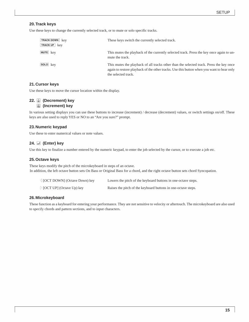
20.Track keys
Use these keys to change the currently selected track, or to mute or solo specific tracks.
d key These keys switch the currently selected track.u key
m key This mutes the playback of the currently selected track. Press the key once again to un-mute the track.
s key This mutes the playback of all tracks other than the selected track. Press the key onceagain to restore playback of the other tracks. Use this button when you want to hear onlythe selected track.
21.Cursor keys
Use these keys to move the cursor location within the display.
22.n (Decrement) keyy (Increment) key
In various setting displays you can use these buttons to increase (increment) / decrease (decrement) values, or switch settings on/off. Thesekeys are also used to reply YES or NO to an “Are you sure?” prompt.
23.Numeric keypad
Use these to enter numerical values or note values.
24.e (Enter) key
Use this key to finalize a number entered by the numeric keypad, to enter the job selected by the cursor, or to execute a job etc.
25.Octave keys
These keys modify the pitch of the microkeyboard in steps of an octave.In addition, the left octave button sets On Bass or Original Bass for a chord, and the right octave button sets chord Syncopation.
d[OCT DOWN] (Octave Down) key Lowers the pitch of the keyboard buttons in one-octave steps.
u[OCT UP] (Octave Up) key Raises the pitch of the keyboard buttons in one-octave steps.
26.Microkeyboard
These function as a keyboard for entering your performance. They are not sensitive to velocity or aftertouch. The microkeyboard are also usedto specify chords and pattern sections, and to input characters.
16
SETUP
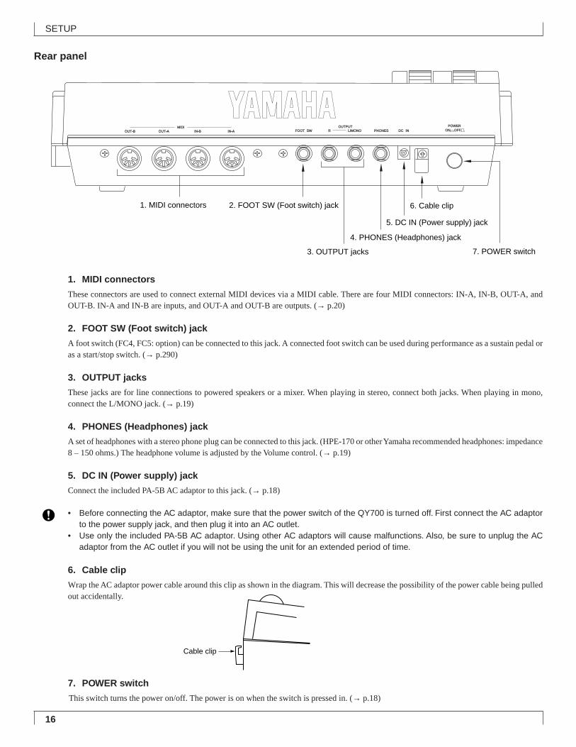
Rear panel
1. MIDI connectors
These connectors are used to connect external MIDI devices via a MIDI cable. There are four MIDI connectors: IN-A, IN-B, OUT-A, andOUT-B. IN-A and IN-B are inputs, and OUT-A and OUT-B are outputs. (→ p.20)
2. FOOT SW (Foot switch) jack
A foot switch (FC4, FC5: option) can be connected to this jack. A connected foot switch can be used during performance as a sustain pedal oras a start/stop switch. (→ p.290)
3. OUTPUT jacks
These jacks are for line connections to powered speakers or a mixer. When playing in stereo, connect both jacks. When playing in mono,connect the L/MONO jack. (→ p.19)
4. PHONES (Headphones) jack
A set of headphones with a stereo phone plug can be connected to this jack. (HPE-170 or other Yamaha recommended headphones: impedance8 – 150 ohms.) The headphone volume is adjusted by the Volume control. (→ p.19)
5. DC IN (Power supply) jack
Connect the included PA-5B AC adaptor to this jack. (→ p.18)
• Before connecting the AC adaptor, make sure that the power switch of the QY700 is turned off. First connect the AC adaptorto the power supply jack, and then plug it into an AC outlet.
• Use only the included PA-5B AC adaptor. Using other AC adaptors will cause malfunctions. Also, be sure to unplug the ACadaptor from the AC outlet if you will not be using the unit for an extended period of time.
6. Cable clip
Wrap the AC adaptor power cable around this clip as shown in the diagram. This will decrease the possibility of the power cable being pulledout accidentally.
7. POWER switch
This switch turns the power on/off. The power is on when the switch is pressed in. (→ p.18)
POWERONINDCPHONESL/MONORSWFOOTIN-AIN-BOUT-AOUT-B
MIDI OUTPUTOFF
1. MIDI connectors
3. OUTPUT jacks
2. FOOT SW (Foot switch) jack
5. DC IN (Power supply) jack
7. POWER switch
4. PHONES (Headphones) jack
6. Cable clip
Cable clip

17
SETUP
Floppy disk drive1. Floppy disk slot
This is where floppy disks are inserted for loading or saving data. 3.5 inch 2HD (MF2HD) or 2DD (MF2DD) floppy disks can be used. (→p.302)
2. Disk-in-use indicator
This indicator will light while data is being read from or written to the floppy disk. Never attempt to remove the disk while this indicator is lit.
3. Eject button
Press this button to remove the floppy disk. Disks must be inserted or removed gently and firmly, and only while the access indicator is dark.
• The back of a floppy disk contains a write protect tab as shown in the following illustration. When this tab is in the downward position (withthe window open), it will not be possible to modify, add, or delete data. When you wish to protect important data, you should leave the tabin this position.
• Be aware that Yamaha can make no guarantee regarding data damage that results from improper use.
1. Floppy disk slot
2. Disk-in-use indicator 3. Eject button
Write protect tab
Write permit
Write prohibit
18
SETUP
2. Connections
In order to use the QY700, the included AC adaptor and an amp system etc. must be connected. If you use external MIDI devices or controllers, thesemust also be connected.This sections explains how to make these connections.
• Be sure to turn off the power before making any connections. If you make connections while the power is on, you risk damag-ing external equipment such as the amp or speakers.
Power supply connections1. Make sure that the power switch of the QY700 is turned off, and connect the included AC adaptor (PA-5B) to the power supply jack.2. Plug the AC adaptor into an AC outlet, and turn on the QY700 power switch.
• Use only the included PA-5B AC adaptor. Using other AC adaptors will cause malfunctions. Also, be sure to unplug the ACadaptor from the AC outlet if you will not be using the unit for an extended period of time.
19
SETUP
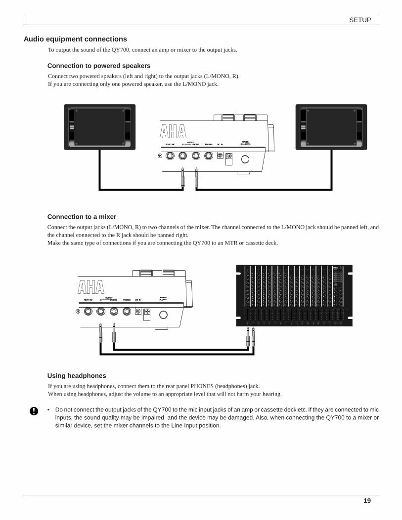
Audio equipment connectionsTo output the sound of the QY700, connect an amp or mixer to the output jacks.
Connection to powered speakers
Connect two powered speakers (left and right) to the output jacks (L/MONO, R).If you are connecting only one powered speaker, use the L/MONO jack.
Connection to a mixer
Connect the output jacks (L/MONO, R) to two channels of the mixer. The channel connected to the L/MONO jack should be panned left, andthe channel connected to the R jack should be panned right.Make the same type of connections if you are connecting the QY700 to an MTR or cassette deck.
Using headphones
If you are using headphones, connect them to the rear panel PHONES (headphones) jack.When using headphones, adjust the volume to an appropriate level that will not harm your hearing.
• Do not connect the output jacks of the QY700 to the mic input jacks of an amp or cassette deck etc. If they are connected to micinputs, the sound quality may be impaired, and the device may be damaged. Also, when connecting the QY700 to a mixer orsimilar device, set the mixer channels to the Line Input position.
POWERONINDCPHONESL/MONORSWFOOT
OUTPUTOFF
60
5
10
0
5
10
20
60
5
10
0
5
10
20
60
5
10
0
5
10
20
60
5
10
0
5
10
20
60
5
10
0
5
10
20
60
5
10
0
5
10
20
60
5
10
0
5
10
20
60
5
10
0
5
10
20
60
5
10
0
5
10
20
60
5
10
0
5
10
20
60
5
10
0
5
10
20
60
5
10
0
5
10
20
60
5
10
0
5
10
20
60
5
10
0
5
10
20
60
5
10
0
5
10
20
60
5
10
0
5
10
20
60
5
10
0
5
10
20
60
5
10
0
5
10
20
60
5
10
0
5
10
20
60
5
10
0
5
10
20
1 2 4 5 6 7 8 9 10 12 13 14 15 16 ST R ST ST
2
6016
6016
6016
6016
6016
6016
6016
6016
6016
2
6016
6016
6016
6016
6016
6016
6016
6016
6016
2
6016
6016
6016
6016
6016
6016
6016
6016
6016
2
6016
6016
6016
6016
6016
6016
6016
6016
6016
2
6016
6016
6016
6016
6016
6016
6016
6016
6016
2
6016
6016
6016
6016
6016
6016
6016
6016
6016
2
6016
6016
6016
6016
6016
6016
6016
6016
6016
2
6016
6016
6016
6016
6016
6016
6016
6016
6016
2
6016
6016
6016
6016
6016
6016
6016
6016
2
6016
6016
6016
6016
6016
6016
6016
6016
2
6016
6016
6016
6016
6016
6016
6016
6016
2
6016
6016
6016
6016
6016
6016
6016
6016
2
6016
6016
6016
6016
6016
6016
6016
6016
2
6016
6016
6016
6016
6016
6016
6016
6016
2
6016
6016
6016
6016
6016
6016
6016
6016
2
6016
6016
6016
6016
6016
6016
6016
6016
6016
6016
6016
6016
6016
6016
6016
6016
6016
6016
605605605605605
605605605605605
POWERONINDCPHONESL/MONORSWFOOT
OUTPUTOFF
20
SETUP
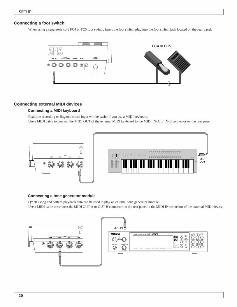
Connecting a foot switchWhen using a separately sold FC4 or FC5 foot switch, insert the foot switch plug into the foot switch jack located on the rear panel.
Connecting external MIDI devicesConnecting a MIDI keyboard
Realtime recording or fingered chord input will be easier if you use a MIDI keyboard.Use a MIDI cable to connect the MIDI OUT of the external MIDI keyboard to the MIDI IN-A or IN-B connector on the rear panel.
Connecting a tone generator module
QY700 song and pattern playback data can be used to play an external tone generator module.Use a MIDI cable to connect the MIDI OUT-A or OUT-B connector on the rear panel to the MIDI IN connector of the external MIDI device.
IN-AIN-BOUT-AOUT-BMIDI
MIDIOUT
A B C D
IN-AIN-BOUT-AOUT-BMIDI
MIDI IN
A/DINPUT
PHONES POWER/VOL
PUSH ON/OFF
PART MIDI BANK/PGM# VOL EXP PAN REV CHO VAR KEY
XGTG300BC/MPERFORM
PLAY EDIT
UTIL EFFECT
MODE EQ
MUTE/SOLO
ENTER
EXIT
PART
SELECT
VALUE
ALL
POWERONINDCPHONESL/MONORSWFOOT
OUTPUTOFF
FC4 or FC5
21
SETUP
OCTDOWN
OCTUP
OCTDOWN
OCTUP
ONBASS
F #
E F G A B C DM
add9
M7
add9
a
m
mM7
m6
c
C # D #
REST
TRACKDOWN
TRACKUP
SOLOMUTE
EDIT
CONTRAST
OUT BOUT AIN B
IN B
MIDI
MIDIOUT BOUT A
IN A
IN A
PLAYREC
JOB
LOC 2LOC 1
TIE
7(#5)
7( b5)
7(#9) 7sus4
sus4
SECTION A
G b D b E b 7( b9)
m7(b5)
M7(9)
6
6(9)
7
7(9) m7(9)
m7
dimZWV
/
HGF
UTSRQPO#
N
CBA
?MLK
_ ! S % &
E)
D(
_
YX
aug
7( b13)
7(13) 7(#11)
JI m7(11)
ORGBASS
CAPS SHIFT SPACE
3
DEL
YESNO
c
G #A b
A #B b
7 8 9
4 5 6
1 2 3
0 -
VOICE
SHIFT F1 F2 F3 F4 F5 F6 SHIFT EXIT
-1 +1
MAXVOLUME
EFFECT DISK
SONG
PITCH ASSIGNABLE
PATTERN UTILITY
3
B C D E F G H
FOOT SWRL/MONOOUTPUT
MUSIC SEQUENCER
MTR(MTC,MMC-compatible)
MIDI OUTMIDI IN-A or IN-B
OCTDOWN
OCTUP
OCTDOWN
OCTUP
ONBASS
F #
E F G A B C DM
add9
M7
add9
a
m
mM7
m6
c
C # D #
REST
TRACKDOWN
TRACKUP
SOLOMUTE
EDIT
CONTRAST
OUT BOUT AIN B
IN B
MIDI
MIDIOUT BOUT A
IN A
IN A
PLAYREC
JOB
LOC 2LOC 1
TIE
7(#5)
7( b5)
7(#9) 7sus4
sus4
SECTION A
G b D b E b 7( b9)
m7(b5)
M7(9)
6
6(9)
7
7(9) m7(9)
m7
dimZWV
/
HGF
UTSRQPO#
N
CBA
?MLK
_ ! S % &
E)
D(
_
YX
aug
7( b13)
7(13) 7(#11)
JI m7(11)
ORGBASS
CAPS SHIFT SPACE
3
DEL
YESNO
c
G #A b
A #B b
7 8 9
4 5 6
1 2 3
0 -
VOICE
SHIFT F1 F2 F3 F4 F5 F6 SHIFT EXIT
-1 +1
MAXVOLUME
EFFECT DISK
SONG
PITCH ASSIGNABLE
PATTERN UTILITY
3
B C D E F G H
FOOT SWRL/MONOOUTPUT
MUSIC SEQUENCER
MTR(MTC,MMC-compatible)
MIDI IN
MIDI OUT-A or OUT-B
Synchronizing the QY700 by MTC from an external device
Controlling an external device via MMC from the QY700
A B C D
A/DINPUT
PHONES POWER/VOL
PUSH ON/OFF
PART MIDI BANK/PGM# VOL EXP PAN REV CHO VAR KEY
XGTG300BC/MPERFORM
PLAY EDIT
UTIL EFFECT
MODE EQ
MUTE/SOLO
ENTER
EXIT
PART
SELECT
VALUE
ALL OCTDOWN
OCTUP
OCTDOWN
OCTUP
ONBASS
F#
E F G A B C DM
add9
M7
add9
a
m
mM7
m6
c
C# D#
REST
TRACKDOWN
TRACKUP
SOLOMUTE
EDIT
CONTRAST
OUT BOUT AIN B
IN B
MIDI
MIDIOUT BOUT A
IN A
IN A
PLAYREC
JOB
LOC 2LOC 1
TIE
7(#5)
7(b5)
7(#9) 7sus4
sus4
SECTION A
Gb Db Eb 7(b9)
m7(b5)
M7(9)
6
6(9)
7
7(9) m7(9)
m7
dimZWV
/
HGF
UTSRQPO#
N
CBA
?MLK
_ ! S % &
E)
D(
_
YX
aug
7(b13)
7(13) 7(#11)
JI m7(11)
ORGBASS
CAPS SHIFT SPACE
3
DEL
YESNO
c
G#
AbA#
Bb
7 8 9
4 5 6
1 2 3
0 -
VOICE
SHIFT F1 F2 F3 F4 F5 F6 SHIFT EXIT
-1 +1
MAXVOLUME
EFFECT DISK
SONG
PITCH ASSIGNABLE
PATTERN UTILITY
3
B C D E F G H
FOOT SWRL/MONOOUTPUT
MUSIC SEQUENCER
MTR (MTC/MMC-compatible)
MIDI OUTMIDI OUT
MIDI IN
MIDI IN
MIDI OUT-B
MIDI IN-BMIDI IN-A
MIDI OUT-A
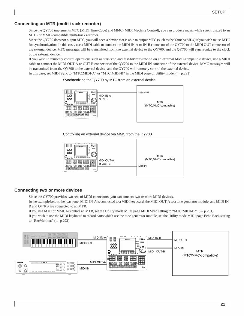
Connecting an MTR (multi-track recorder)Since the QY700 implements MTC (MIDI Time Code) and MMC (MIDI Machine Control), you can produce music while synchronized to anMTC- or MMC-compatible multi-track recorder.Since the QY700 does not output MTC, you will need a device that is able to output MTC (such as the Yamaha MD4) if you wish to use MTCfor synchronization. In this case, use a MIDI cable to connect the MIDI IN-A or IN-B connector of the QY700 to the MIDI OUT connector ofthe external device. MTC messages will be transmitted from the external device to the QY700, and the QY700 will synchronize to the clockof the external device.If you wish to remotely control operations such as start/stop and fast-forward/rewind on an external MMC-compatible device, use a MIDIcable to connect the MIDI OUT-A or OUT-B connector of the QY700 to the MIDI IN connector of the external device. MMC messages willbe transmitted from the QY700 to the external device, and the QY700 will remotely control the external device.In this case, set MIDI Sync to “MTC:MIDI-A” or “MTC:MIDI-B” in the MIDI page of Utility mode. (→ p.291)
Connecting two or more devicesSince the QY700 provides two sets of MIDI connectors, you can connect two or more MIDI devices.In the example below, the rear panel MIDI IN-A is connected to a MIDI keyboard, the MIDI OUT-A to a tone generator module, and MIDI IN-B and OUT-B are connected to an MTR.If you use MTC or MMC to control an MTR, set the Utility mode MIDI page MIDI Sync setting to “MTC:MIDI-B.” (→ p.291)If you wish to use the MIDI keyboard to record parts which use the tone generator module, set the Utility mode MIDI page Echo Back settingto “RecMonitor.” (→ p.292)
22
SETUP
3. Using the Style and Demonstration disk
Here’s how to use the included “STYLE & DEMONSTRATION” disk.
Contents of the disk• The included disk contains “STYLE,” “DEMO 1” and
“DEMO 2.”• “DEMO 1” and “DEMO 2” allow you to enjoy demo play-
back, and to playback songs while adjusting the Play Ef-fects or Multi to experience the possibilities of the QY700.
• “STYLE” allows you to restore the factory settings of theQY700.
Listening to the demo playback• Here’s how to load a demo song file from disk and enjoy
the demo playback.
• When “DEMO 1” or “DEMO 2” is loaded from disk, allinternal memory will be rewritten by the demo play-back data. If internal memory contains any importantdata that you wish to keep, save the data before load-ing the demo.
1. With the label facing upward, insert the disk into thefloppy disk slot.
▼ Insert the disk all the way until it clicks into place.
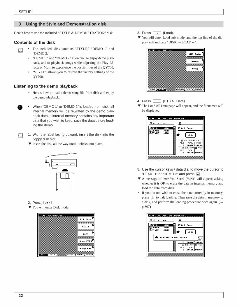
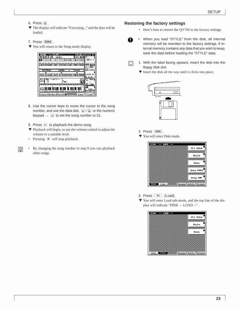
2. Press d.▼ You will enter Disk mode.
3. Press 2 (Load).▼ You will enter Load sub-mode, and the top line of the dis-
play will indicate “DISK -- LOAD --”.
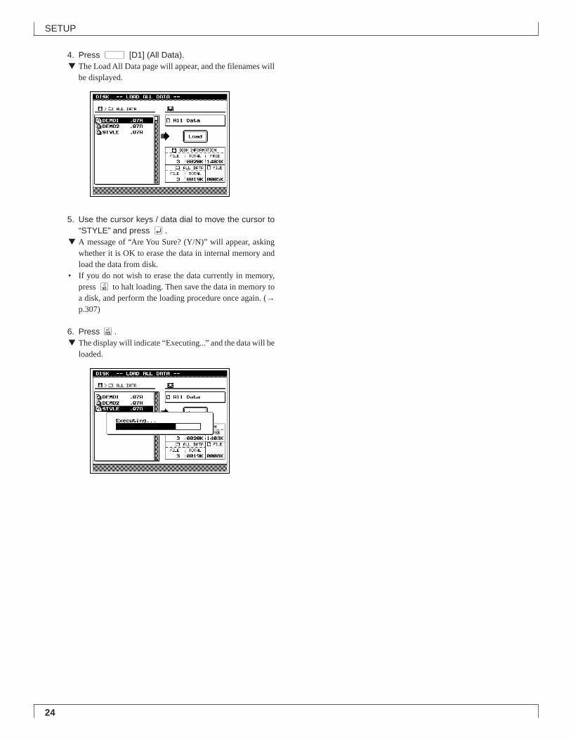
4. Press d [D1] (All Data).▼ The Load All Data page will appear, and the filenames will
be displayed.
5. Use the cursor keys / data dial to move the cursor to“DEMO 1” or “DEMO 2” and press e.
▼ A message of “Are You Sure? (Y/N)” will appear, askingwhether it is OK to erase the data in internal memory andload the data from disk.
• If you do not wish to erase the data currently in memory,press n to halt loading. Then save the data in memory toa disk, and perform the loading procedure once again. (→p.307)
23
SETUP
6. Press y.▼ The display will indicate “Executing...” and the data will be
loaded.
7. Press s.▼ You will return to the Song mode display.
8. Use the cursor keys to move the cursor to the songnumber, and use the data dial, n/y or the numerickeypad → e to set the song number to 01.
9. Press r to playback the demo song.▼ Playback will begin, so use the volume control to adjust the
volume to a suitable level.• Pressing s will stop playback.
• By changing the song number in step 8 you can playbackother songs.
Restoring the factory settings• Here’s how to restore the QY700 to the factory settings.
• When you load “STYLE” from the disk, all internalmemory will be rewritten to the factory settings. If in-ternal memory contains any data that you wish to keep,save the data before loading the “STYLE” data.
1. With the label facing upward, insert the disk into thefloppy disk slot.
▼ Insert the disk all the way until it clicks into place.
2. Press d.▼ You will enter Disk mode.
3. Press 2 (Load).▼ You will enter Load sub-mode, and the top line of the dis-
play will indicate “DISK -- LOAD --”.
24
SETUP
4. Press d [D1] (All Data).▼ The Load All Data page will appear, and the filenames will
be displayed.
5. Use the cursor keys / data dial to move the cursor to“STYLE” and press e.
▼ A message of “Are You Sure? (Y/N)” will appear, askingwhether it is OK to erase the data in internal memory andload the data from disk.
• If you do not wish to erase the data currently in memory,press n to halt loading. Then save the data in memory toa disk, and perform the loading procedure once again. (→p.307)
6. Press y.▼ The display will indicate “Executing...” and the data will be
loaded.
Chapter 1. BASIC CONCEPTS
This chapter explains the basic concepts that you need to know be-
fore use, such as the mode structure and the internal structure of
the QY700.
1
1. Mode structure ........................................... 262. Function tree .............................................. 343. How the QY700 is organized...................... 364. Sequencer block ........................................ 375. The tone generator block ........................... 436. Controller block .......................................... 467. Effect block ................................................. 478. Basic operation .......................................... 519. Song creating procedure ............................ 56
26
BASIC CONCEPTS
Chapter 1
1. Mode structure
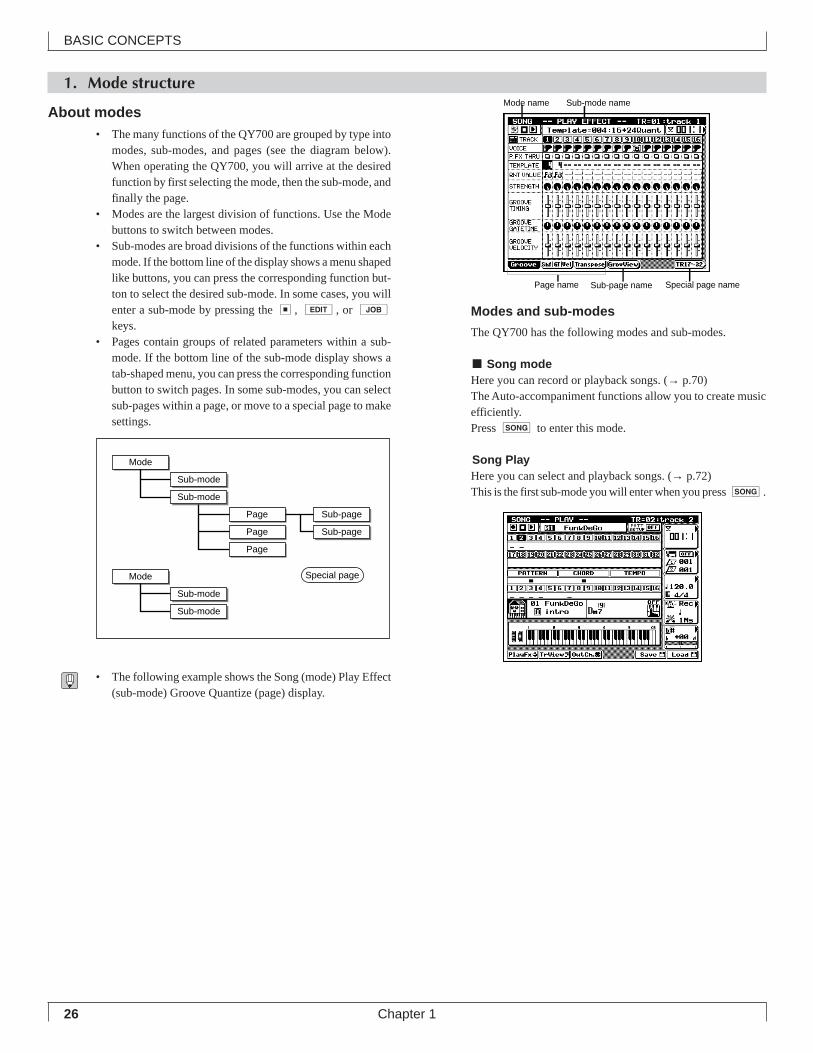
About modes• The many functions of the QY700 are grouped by type into
modes, sub-modes, and pages (see the diagram below).When operating the QY700, you will arrive at the desiredfunction by first selecting the mode, then the sub-mode, andfinally the page.
• Modes are the largest division of functions. Use the Modebuttons to switch between modes.
• Sub-modes are broad divisions of the functions within eachmode. If the bottom line of the display shows a menu shapedlike buttons, you can press the corresponding function but-ton to select the desired sub-mode. In some cases, you willenter a sub-mode by pressing the s, e, or jkeys.
• Pages contain groups of related parameters within a sub-mode. If the bottom line of the sub-mode display shows atab-shaped menu, you can press the corresponding functionbutton to switch pages. In some sub-modes, you can selectsub-pages within a page, or move to a special page to makesettings.
• The following example shows the Song (mode) Play Effect(sub-mode) Groove Quantize (page) display.
Modes and sub-modes
The QY700 has the following modes and sub-modes.
■ Song modeHere you can record or playback songs. (→ p.70)The Auto-accompaniment functions allow you to create musicefficiently.Press s to enter this mode.
Song PlayHere you can select and playback songs. (→ p.72)This is the first sub-mode you will enter when you press s.
Mode
Sub-mode
Sub-mode
Mode
Sub-mode
Sub-mode
Special page
Page
Page
Page
Sub-page
Sub-page
Mode name Sub-mode name
Page name Sub-page name Special page name
27
BASIC CONCEPTS
Chapter 1
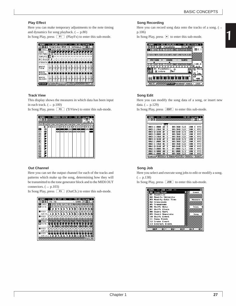
1Song RecordingHere you can record song data onto the tracks of a song. (→p.106)In Song Play, press e to enter this sub-mode.
Song EditHere you can modify the song data of a song, or insert newdata. (→ p.129)In Song Play, press e to enter this sub-mode.
Song JobHere you select and execute song jobs to edit or modify a song.(→ p.138)In Song Play, press j to enter this sub-mode.
Play EffectHere you can make temporary adjustments to the note timingand dynamics for song playback. (→ p.80)In Song Play, press 1 (PlayFx) to enter this sub-mode.
Track ViewThis display shows the measures in which data has been inputin each track. (→ p.100)In Song Play, press 2 (TrView) to enter this sub-mode.
Out ChannelHere you can set the output channel for each of the tracks andpatterns which make up the song, determining how they willbe transmitted to the tone generator block and to the MIDI OUTconnectors. (→ p.103)In Song Play, press 3 (OutCh.) to enter this sub-mode.
28
BASIC CONCEPTS
Chapter 1
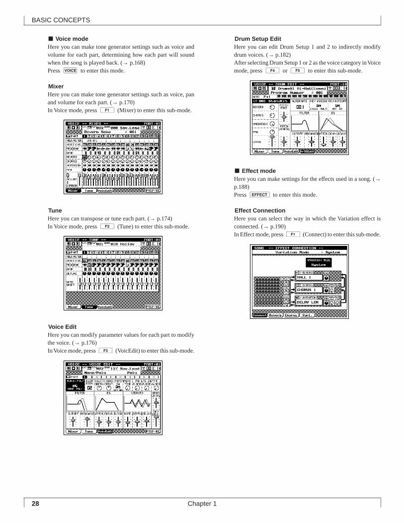
■ Voice modeHere you can make tone generator settings such as voice andvolume for each part, determining how each part will soundwhen the song is played back. (→ p.168)Press v to enter this mode.
MixerHere you can make tone generator settings such as voice, panand volume for each part. (→ p.170)In Voice mode, press 1 (Mixer) to enter this sub-mode.
TuneHere you can transpose or tune each part. (→ p.174)In Voice mode, press 2 (Tune) to enter this sub-mode.
Voice EditHere you can modify parameter values for each part to modifythe voice. (→ p.176)In Voice mode, press 3 (VoicEdit) to enter this sub-mode.
Drum Setup EditHere you can edit Drum Setup 1 and 2 to indirectly modifydrum voices. (→ p.182)After selecting Drum Setup 1 or 2 as the voice category in Voicemode, press 4 or 5 to enter this sub-mode.
■ Effect modeHere you can make settings for the effects used in a song. (→p.188)Press e to enter this mode.
Effect ConnectionHere you can select the way in which the Variation effect isconnected. (→ p.190)In Effect mode, press 1 (Connect) to enter this sub-mode.
29
BASIC CONCEPTS
Chapter 1
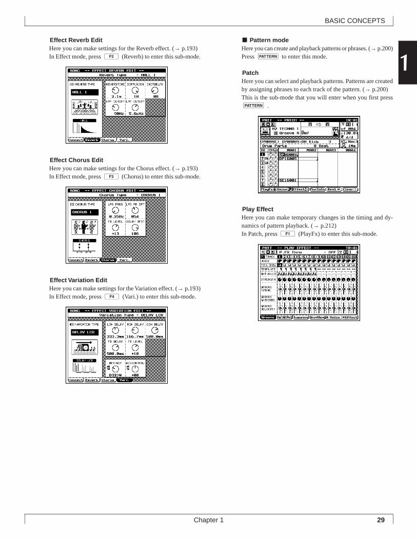
1Effect Reverb EditHere you can make settings for the Reverb effect. (→ p.193)In Effect mode, press 2 (Reverb) to enter this sub-mode.
Effect Chorus EditHere you can make settings for the Chorus effect. (→ p.193)In Effect mode, press 3 (Chorus) to enter this sub-mode.
Effect Variation EditHere you can make settings for the Variation effect. (→ p.193)In Effect mode, press 4 (Vari.) to enter this sub-mode.
■ Pattern modeHere you can create and playback patterns or phrases. (→ p.200)Press p to enter this mode.
PatchHere you can select and playback patterns. Patterns are createdby assigning phrases to each track of the pattern. (→ p.200)This is the sub-mode that you will enter when you first pressp .
Play EffectHere you can make temporary changes in the timing and dy-namics of pattern playback. (→ p.212)In Patch, press 1 (PlayFx) to enter this sub-mode.
30
BASIC CONCEPTS
Chapter 1
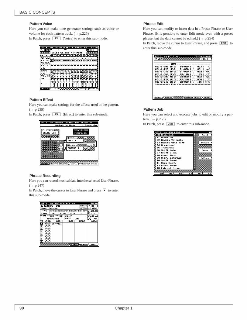
Pattern VoiceHere you can make tone generator settings such as voice orvolume for each pattern track. (→ p.225)In Patch, press 2 (Voice) to enter this sub-mode.
Pattern EffectHere you can make settings for the effects used in the pattern.(→ p.239)In Patch, press 3 (Effect) to enter this sub-mode.
Phrase RecordingHere you can record musical data into the selected User Phrase.(→ p.247)In Patch, move the cursor to User Phrase and press e to enterthis sub-mode.
Phrase EditHere you can modify or insert data in a Preset Phrase or UserPhrase. (It is possible to enter Edit mode even with a presetphrase, but the data cannot be edited.) (→ p.254)In Patch, move the cursor to User Phrase, and press e toenter this sub-mode.
Pattern JobHere you can select and execute jobs to edit or modify a pat-tern. (→ p.256)In Patch, press j to enter this sub-mode.
31
BASIC CONCEPTS
Chapter 1
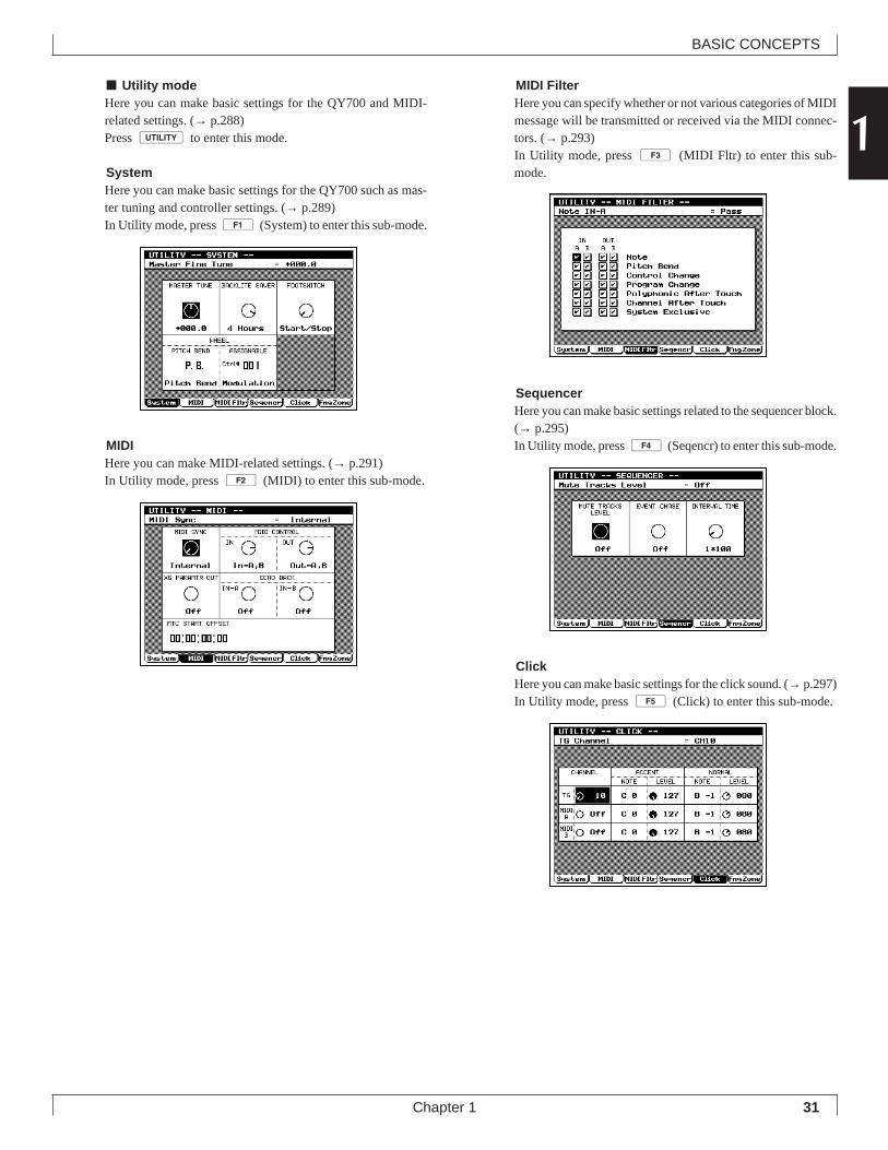
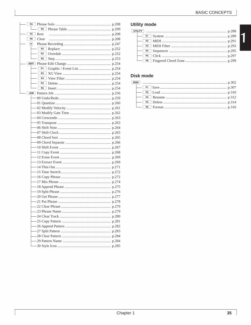
1■ Utility modeHere you can make basic settings for the QY700 and MIDI-related settings. (→ p.288)Press u to enter this mode.
SystemHere you can make basic settings for the QY700 such as mas-ter tuning and controller settings. (→ p.289)In Utility mode, press 1 (System) to enter this sub-mode.
MIDIHere you can make MIDI-related settings. (→ p.291)In Utility mode, press 2 (MIDI) to enter this sub-mode.
MIDI FilterHere you can specify whether or not various categories of MIDImessage will be transmitted or received via the MIDI connec-tors. (→ p.293)In Utility mode, press 3 (MIDI Fltr) to enter this sub-mode.
SequencerHere you can make basic settings related to the sequencer block.(→ p.295)In Utility mode, press 4 (Seqencr) to enter this sub-mode.
ClickHere you can make basic settings for the click sound. (→ p.297)In Utility mode, press 5 (Click) to enter this sub-mode.
32
BASIC CONCEPTS
Chapter 1
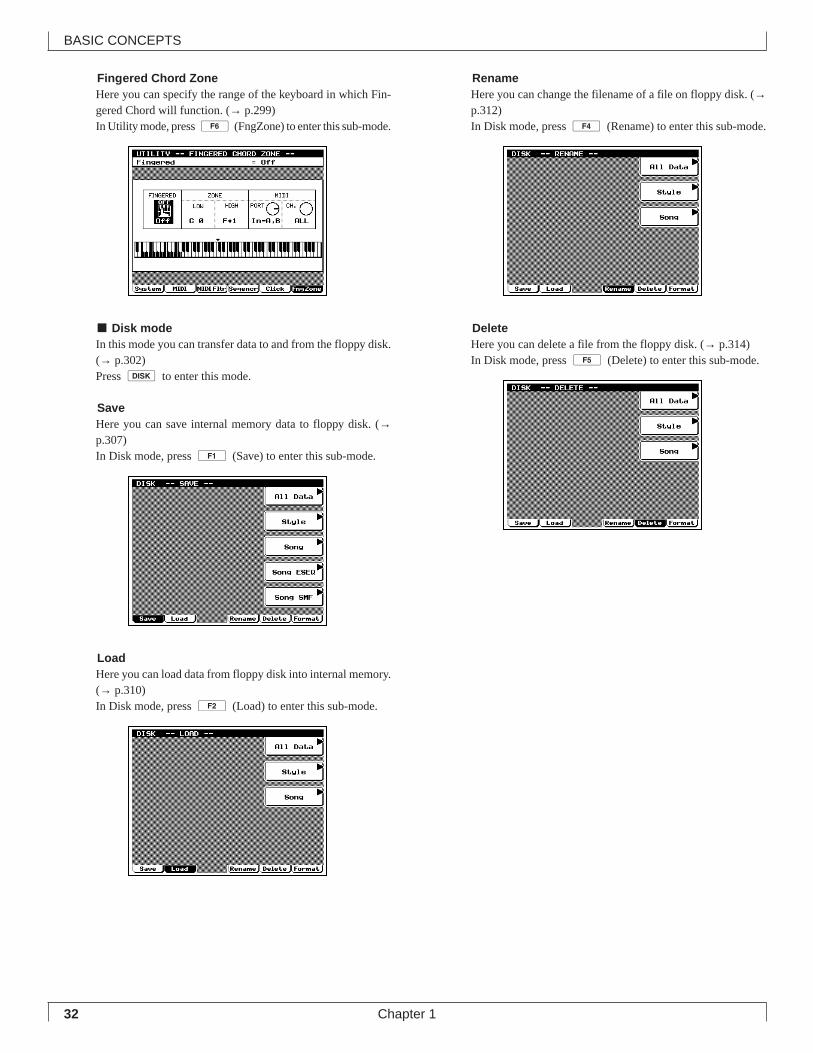
Fingered Chord ZoneHere you can specify the range of the keyboard in which Fin-gered Chord will function. (→ p.299)In Utility mode, press 6 (FngZone) to enter this sub-mode.
■ Disk modeIn this mode you can transfer data to and from the floppy disk.(→ p.302)Press d to enter this mode.
SaveHere you can save internal memory data to floppy disk. (→p.307)In Disk mode, press 1 (Save) to enter this sub-mode.
LoadHere you can load data from floppy disk into internal memory.(→ p.310)In Disk mode, press 2 (Load) to enter this sub-mode.
RenameHere you can change the filename of a file on floppy disk. (→p.312)In Disk mode, press 4 (Rename) to enter this sub-mode.
DeleteHere you can delete a file from the floppy disk. (→ p.314)In Disk mode, press 5 (Delete) to enter this sub-mode.
33
BASIC CONCEPTS
Chapter 1
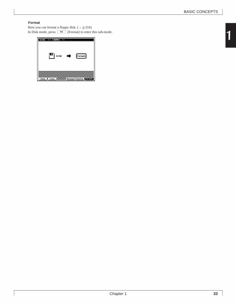
1FormatHere you can format a floppy disk. (→ p.316)In Disk mode, press 6 (Format) to enter this sub-mode.
34
BASIC CONCEPTS
Chapter 1
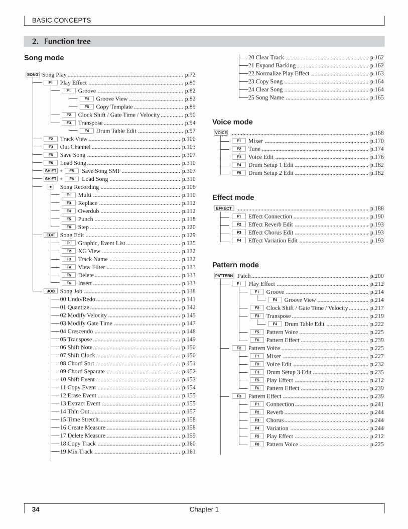
2. Function tree
Song mode
sSong Play ............................................................................. p.721Play Effect ............................................................... p.80
1Groove ......................................................... p.824Groove View .................................... p.825Copy Template ................................. p.89
2Clock Shift / Gate Time / Velocity ............... p.903Transpose ..................................................... p.94
4Drum Table Edit .............................. p.972Track View ............................................................. p.1003Out Channel ........................................................... p.1035Save Song .............................................................. p.3076Load Song .............................................................. p.310s+5 Save Song SMF ....................................... p.307s+6 Load Song ............................................... p.310e Song Recording ..................................................... p.106
1Multi .......................................................... p.1103Replace ...................................................... p.1124Overdub ..................................................... p.1125Punch ......................................................... p.1186Step ............................................................ p.120
eSong Edit ............................................................... p.1291Graphic, Event List .................................... p.1352XG View .................................................... p.1323Track Name ............................................... p.1324View Filter ................................................. p.1335Delete ......................................................... p.1336 Insert .......................................................... p.133
jSong Job ................................................................ p.13800 Undo/Redo ........................................................ p.14101 Quantize ............................................................ p.14202 Modify Velocity ................................................ p.14503 Modify Gate Time ............................................ p.14704 Crescendo ......................................................... p.14805 Transpose .......................................................... p.14906 Shift Note .......................................................... p.15007 Shift Clock ........................................................ p.15008 Chord Sort ........................................................ p.15109 Chord Separate ................................................. p.15210 Shift Event ........................................................ p.15311 Copy Event ....................................................... p.15412 Erase Event ....................................................... p.15513 Extract Event .................................................... p.15514 Thin Out ............................................................ p.15715 Time Stretch...................................................... p.15816 Create Measure ................................................. p.15817 Delete Measure ................................................. p.15918 Copy Track ....................................................... p.16019 Mix Track ......................................................... p.161
20 Clear Track ....................................................... p.16221 Expand Backing................................................ p.16222 Normalize Play Effect ...................................... p.16323 Copy Song ........................................................ p.16424 Clear Song ........................................................ p.16425 Song Name ....................................................... p.165
Voice modev ........................................................................................... p.168
1Mixer ..................................................................... p.1702Tune ....................................................................... p.1743Voice Edit .............................................................. p.1764Drum Setup 1 Edit ................................................. p.1825Drum Setup 2 Edit ................................................. p.182
Effect modee ....................................................................................... p.188
1Effect Connection .................................................. p.1902Effect Reverb Edit ................................................. p.1933Effect Chorus Edit ................................................. p.1934Effect Variation Edit .............................................. p.193
Pattern modep Patch.............................................................................. p.200
1Play Effect ............................................................. p.2121Groove ....................................................... p.214
4Groove View .................................. p.2142Clock Shift / Gate Time / Velocity ............. p.2173Transpose ................................................... p.219
4Drum Table Edit ............................ p.2225Pattern Voice .............................................. p.2256Pattern Effect ............................................. p.239
2Pattern Voice .......................................................... p.2251Mixer ......................................................... p.2272Voice Edit .................................................. p.2323Drum Setup 3 Edit ..................................... p.2355Play Effect ................................................. p.2126Pattern Effect ............................................. p.239
3Pattern Effect ......................................................... p.2391Connection ................................................. p.2412Reverb ........................................................ p.2443Chorus........................................................ p.2444Variation .................................................... p.2445Play Effect ................................................. p.2126Pattern Voice .............................................. p.225
35
BASIC CONCEPTS
Chapter 1
14Phrase Solo ............................................................ p.208
6Phrase Table ............................................... p.2095Rest ................................................................... p.2086Clear ................................................................... p.208e Phrase Recording ................................................... p.247
4Replace ...................................................... p.2525Overdub ..................................................... p.2526Step ............................................................ p.253
ePhrase Edit Change................................................ p.2541Graphic / Event List ................................... p.2542XG View .................................................... p.2544View Filter ................................................. p.2545Delete ......................................................... p.2546 Insert .......................................................... p.254
jPattern Job ............................................................. p.25600 Undo/Redo ........................................................ p.25901 Quantize ............................................................ p.26002 Modify Velocity ................................................ p.26103 Modify Gate Time ............................................ p.26204 Crescendo ......................................................... p.26305 Transpose .......................................................... p.26306 Shift Note.......................................................... p.26407 Shift Clock ........................................................ p.26508 Chord Sort ........................................................ p.26509 Chord Separate ................................................. p.26610 Shift Event ........................................................ p.26711 Copy Event ....................................................... p.26812 Erase Event ....................................................... p.26913 Extract Event .................................................... p.26914 Thin Out ............................................................ p.27115 Time Stretch...................................................... p.27216 Copy Phrase ...................................................... p.27217 Mix Phrase ........................................................ p.27418 Append Phrase .................................................. p.27519 Split Phrase ....................................................... p.27620 Get Phrase ......................................................... p.27721 Put Phrase ......................................................... p.27822 Clear Phrase ...................................................... p.27923 Phrase Name ..................................................... p.27924 Clear Track ....................................................... p.28025 Copy Pattern ..................................................... p.28126 Append Pattern ................................................. p.28227 Split Pattern ...................................................... p.28328 Clear Pattern ..................................................... p.28429 Pattern Name .................................................... p.28430 Style Icon .......................................................... p.285
Utility modeu ....................................................................................... p.288
1System ................................................................... p.2892MIDI ...................................................................... p.2913MIDI Filter ............................................................ p.2934Sequencer .............................................................. p.2955Click ...................................................................... p.2976Fingered Chord Zone ............................................. p.299
Disk moded ........................................................................................... p.302
1Save ........................................................................ p.3072Load ....................................................................... p.3104Rename .................................................................. p.3125Delete ..................................................................... p.3146Format .................................................................... p.316
36
BASIC CONCEPTS
Chapter 1
3. How the QY700 is organized
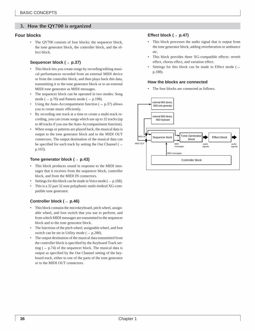
Four blocks• The QY700 consists of four blocks: the sequencer block,
the tone generator block, the controller block, and the ef-fect block.
Sequencer block ( → p.37)
• This block lets you create songs by recording/editing musi-cal performances recorded from an external MIDI deviceor from the controller block, and then plays back this data,transmitting it to the tone generator block or to an externalMIDI tone generator as MIDI messages.
• The sequencer block can be operated in two modes: Songmode (→ p.70) and Pattern mode (→ p.198).
• Using the Auto-Accompaniment function (→ p.37) allowsyou to create music efficiently.
• By recording one track at a time to create a multi-track re-cording, you can create songs which use up to 32 tracks (upto 48 tracks if you use the Auto-Accompaniment function).
• When songs or patterns are played back, the musical data isoutput to the tone generator block and to the MIDI OUTconnectors. The output destination of the musical data canbe specified for each track by setting the Out Channel (→p.103).
Tone generator block ( → p.43)
• This block produces sound in response to the MIDI mes-sages that it receives from the sequencer block, controllerblock, and from the MIDI IN connectors.
• Settings for this block can be made in Voice mode (→ p.168).• This is a 32 part 32 note polyphonic multi-timbral XG-com-
patible tone generator.
Controller block ( → p.46)
• This block contains the microkeyboard, pitch wheel, assign-able wheel, and foot switch that you use to perform, andfrom which MIDI messages are transmitted to the sequencerblock and to the tone generator block.
• The functions of the pitch wheel, assignable wheel, and footswitch can be set in Utility mode (→ p.288).
• The output destination of the musical data transmitted fromthe controller block is specified by the Keyboard Track set-ting (→ p.74) of the sequencer block. The musical data isoutput as specified by the Out Channel setting of the key-board track, either to one of the parts of the tone generatoror to the MIDI OUT connectors.
Effect block ( → p.47)
• This block processes the audio signal that is output fromthe tone generator block, adding reverberation or ambianceetc.
• This block provides three XG-compatible effects: reverbeffect, chorus effect, and variation effect.
• Settings for this block can be made in Effect mode (→p.188).
How the blocks are connected
• The four blocks are connected as follows.
audio signals
MIDI messages
MIDI IN
MIDI OUT audio signals
Controller block
Tone Generator block
Effect blockSequencer block
external MIDI device, MIDI keyboard
external MIDI device, MIDI tone generator
MIDI messages
37
BASIC CONCEPTS
Chapter 1
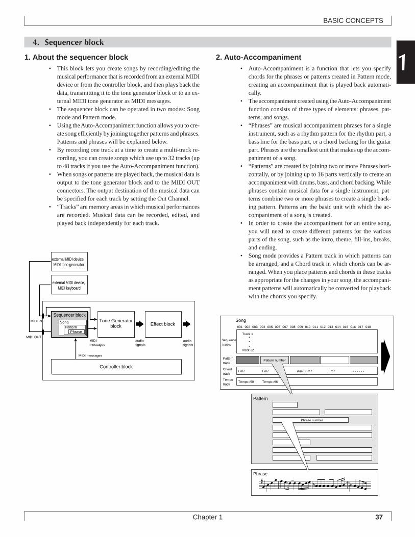
14. Sequencer block
Song001 002 003 004 005 006 007 008 009 010 011 012 013 014 015 016 017 018
Track 1
Track 32
• • •
Sequence tracks
Em7 Em7
Tempo=90 Tempo=96
Em7 • • • Am7 Bm7 • • •
Pattern number
Pattern
Phrase number
Phrase
Pattern track
Chord track
Tempo track
1. About the sequencer block• This block lets you create songs by recording/editing the
musical performance that is recorded from an external MIDIdevice or from the controller block, and then plays back thedata, transmitting it to the tone generator block or to an ex-ternal MIDI tone generator as MIDI messages.
• The sequencer block can be operated in two modes: Songmode and Pattern mode.
• Using the Auto-Accompaniment function allows you to cre-ate song efficiently by joining together patterns and phrases.Patterns and phrases will be explained below.
• By recording one track at a time to create a multi-track re-cording, you can create songs which use up to 32 tracks (upto 48 tracks if you use the Auto-Accompaniment function).
• When songs or patterns are played back, the musical data isoutput to the tone generator block and to the MIDI OUTconnectors. The output destination of the musical data canbe specified for each track by setting the Out Channel.
• “Tracks” are memory areas in which musical performancesare recorded. Musical data can be recorded, edited, andplayed back independently for each track.
2. Auto-Accompaniment• Auto-Accompaniment is a function that lets you specify
chords for the phrases or patterns created in Pattern mode,creating an accompaniment that is played back automati-cally.
• The accompaniment created using the Auto-Accompanimentfunction consists of three types of elements: phrases, pat-terns, and songs.
• “Phrases” are musical accompaniment phrases for a singleinstrument, such as a rhythm pattern for the rhythm part, abass line for the bass part, or a chord backing for the guitarpart. Phrases are the smallest unit that makes up the accom-paniment of a song.
• “Patterns” are created by joining two or more Phrases hori-zontally, or by joining up to 16 parts vertically to create anaccompaniment with drums, bass, and chord backing. Whilephrases contain musical data for a single instrument, pat-terns combine two or more phrases to create a single back-ing pattern. Patterns are the basic unit with which the ac-companiment of a song is created.
• In order to create the accompaniment for an entire song,you will need to create different patterns for the variousparts of the song, such as the intro, theme, fill-ins, breaks,and ending.
• Song mode provides a Pattern track in which patterns canbe arranged, and a Chord track in which chords can be ar-ranged. When you place patterns and chords in these tracksas appropriate for the changes in your song, the accompani-ment patterns will automatically be converted for playbackwith the chords you specify.
audio signals
MIDI messages
audio signals
Controller block
Tone Generatorblock Effect block
Sequencer block
PhrasePattern
SongMIDI IN
MIDI OUT
external MIDI device, MIDI keyboard
MIDI messages
external MIDI device, MIDI tone generator
38
BASIC CONCEPTS
Chapter 1
3. Phrases
• “Phrases” are musical accompaniment phrases for a singleinstrument, such as a rhythm pattern for the rhythm part, abass line for the bass part, or a chord backing for the guitarpart. Phrases are the smallest unit that makes up the accom-paniment of a song.
• The QY700 provides 3,876 Preset Phrases, and 99 UserPhrases for each Style.
• Preset phrases and user phrases are categorized by threeparameters: “instrument category,” “beat” and “number.”This lets you efficiently find desired phrases without hav-ing to be familiar with each individual phrase.
Instrument category
• Instrument category refers to the type of instrument or play-ing technique. There are the following 15 instrument cat-egories. “US” indicates a “User Phrase,” and all others arepreset phrases.
Beat
• Beat categorizes phrases by their basic rhythm, into the fol-lowing three types.
Number
• Number specifies phrases within Instrument Category andBeat by a number 001 – 256. (User phrases are numbered001 – 099.)
4. How chord conversion worksChord conversion table
• The QY700’s “chord conversion table” allows phrases tobe developed and played according to the Chord Root andChord Type that you specify.
• The chord conversion table provides pitch data correspond-ing to 12 chord roots and 28 chord types. The data playedback by a phrase passes through the chord conversion tableand is converted to the pitches that correspond to the chordroot and chord type. In this way, the phrase is developedinto the specified chord.
• The Source Chord indicates the chord with which the phrasewas originally recorded. The source chord plays an impor-tant role in the chord conversion of phrases. This is becausethe original chords must be known in order for the chordsof a phrase to be converted into the specified chords.
• In other words, chord conversion is performed by readingrelative pitch differences between the source chord and thespecified chord from the chord conversion table.
• You can specify the Phrase Type of each phrase so that chordconversion will be performed in a manner appropriate forthe instrument. There are seven phrase types: melody 1 and2, chord 1 and 2, bass, bypass, and parallel. The chord con-version table is switched according to the phrase type.
• The Phrase Type and Source Chord can be set for each phrasein the phrase table (→ p.209).
Da Drum-a Drum phrases
Db Drum-b(General) Drum phrases
Fa Drum Fill-a(Pop & Rock) Drum fill-in phrases
Fb Drum Fill-b(Specific) Drum fill-in phrases
Fc Drum Fill-c(General) Drum fill-in phrases
DP Durm Parts Drum phrases separated by instrument
PC Percussion Percussion phrases
PF Percussion Fill Percussion fill-in phrases
Ba Bass-a Bass phrases
Bb Bass-b(General) Bass phrases
GC Guitar Chord Guitar chord backing phrases
GA Guitar Arpeggio Guitar arpeggio phrases
GR Guitar Riff Guitar riff phrases
KC Keyboard Chord Keyboard chord backing phrases
KA Kbd Arpeggio Keyboard arpeggio phrases
KR Keyboard Riff Keyboard riff phrases
PD Pad Pad-type phrases
BR Brass Brass phrases
SE Sound Effect Sound effect phrases
US User User phrases
Display Category
16 16 beat : 16-beat phrases
08 8 beat : 8-beat phrases
34 3/4 beat : 3/4 time or 6/8 time phrases
Display Type
Chord root
Chord type
Instrument category Beat Number Phrase name
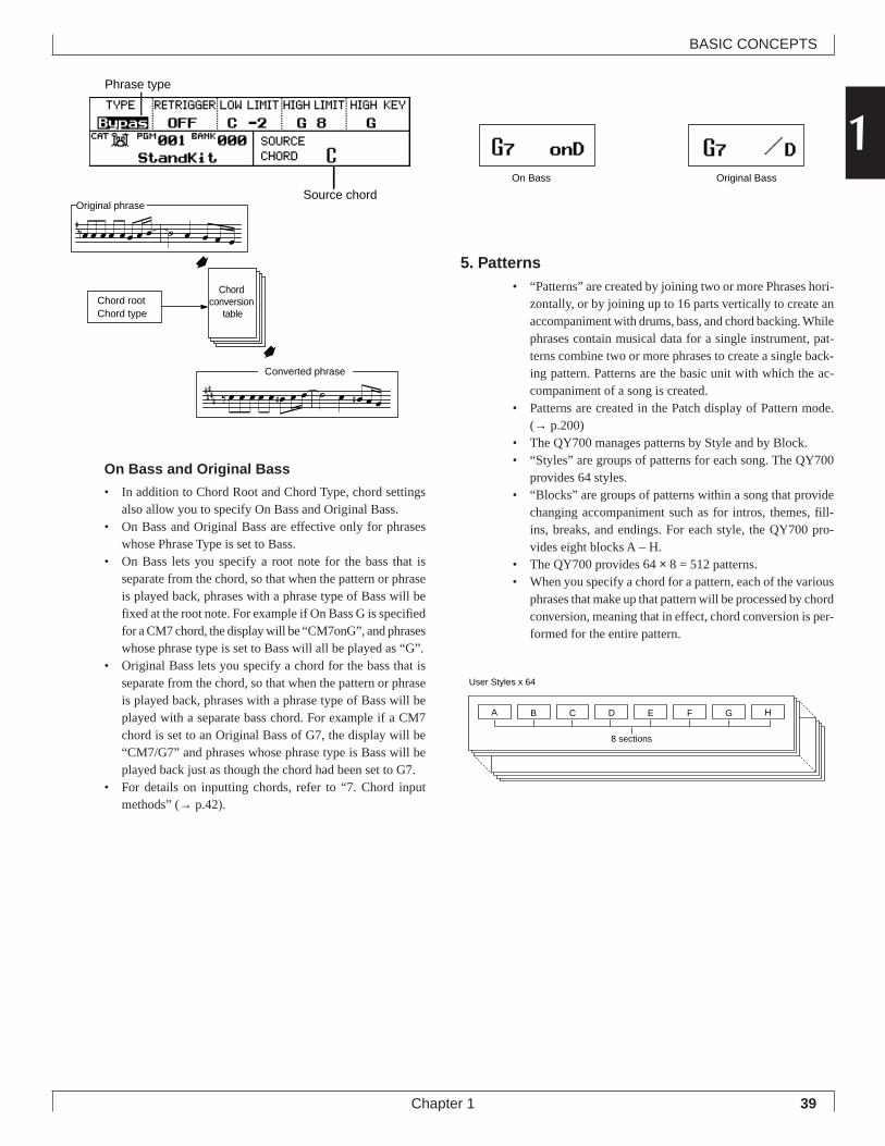
39
BASIC CONCEPTS
Chapter 1
1Phrase type
Source chord
On Bass and Original Bass
• In addition to Chord Root and Chord Type, chord settingsalso allow you to specify On Bass and Original Bass.
• On Bass and Original Bass are effective only for phraseswhose Phrase Type is set to Bass.
• On Bass lets you specify a root note for the bass that isseparate from the chord, so that when the pattern or phraseis played back, phrases with a phrase type of Bass will befixed at the root note. For example if On Bass G is specifiedfor a CM7 chord, the display will be “CM7onG”, and phraseswhose phrase type is set to Bass will all be played as “G”.
• Original Bass lets you specify a chord for the bass that isseparate from the chord, so that when the pattern or phraseis played back, phrases with a phrase type of Bass will beplayed with a separate bass chord. For example if a CM7chord is set to an Original Bass of G7, the display will be“CM7/G7” and phrases whose phrase type is Bass will beplayed back just as though the chord had been set to G7.
• For details on inputting chords, refer to “7. Chord inputmethods” (→ p.42).
5. Patterns• “Patterns” are created by joining two or more Phrases hori-
zontally, or by joining up to 16 parts vertically to create anaccompaniment with drums, bass, and chord backing. Whilephrases contain musical data for a single instrument, pat-terns combine two or more phrases to create a single back-ing pattern. Patterns are the basic unit with which the ac-companiment of a song is created.
• Patterns are created in the Patch display of Pattern mode.(→ p.200)
• The QY700 manages patterns by Style and by Block.• “Styles” are groups of patterns for each song. The QY700
provides 64 styles.• “Blocks” are groups of patterns within a song that provide
changing accompaniment such as for intros, themes, fill-ins, breaks, and endings. For each style, the QY700 pro-vides eight blocks A – H.
• The QY700 provides 64 × 8 = 512 patterns.• When you specify a chord for a pattern, each of the various
phrases that make up that pattern will be processed by chordconversion, meaning that in effect, chord conversion is per-formed for the entire pattern.
äOriginal phrase
äConverted phrase
Chord conversion
tableChord rootChord type
## ## #
#
# #
On Bass Original Bass
A B C D E F G H
8 sections
User Styles x 64
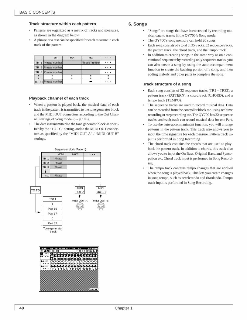
40
BASIC CONCEPTS
Chapter 1
Track structure within each pattern
• Patterns are organized as a matrix of tracks and measures,as shown in the diagram below.
• A phrase or a rest can be specified for each measure in eachtrack of the pattern.
Playback channel of each track
• When a pattern is played back, the musical data of eachtrack in the pattern is transmitted to the tone generator blockand the MIDI OUT connectors according to the Out Chan-nel settings of Song mode. (→ p.103)
• The data is transmitted to the tone generator block as speci-fied by the “TO TG” setting, and to the MIDI OUT connec-tors as specified by the “MIDI OUT-A” / “MIDI OUT-B”settings.
6. Songs• “Songs” are songs that have been created by recording mu-
sical data to tracks in the QY700’s Song mode.• The QY700’s song memory can hold 20 songs.• Each song consists of a total of 35 tracks: 32 sequence tracks,
the pattern track, the chord track, and the tempo track.• In addition to creating songs in the same way as on a con-
ventional sequencer by recording only sequence tracks, youcan also create a song by using the auto-accompanimentfunction to create the backing portion of a song, and thenadding melody and other parts to complete the song.
Track structure of a song
• Each song consists of 32 sequence tracks (TR1 – TR32), apattern track (PATTERN), a chord track (CHORD), and atempo track (TEMPO).
• The sequence tracks are used to record musical data. Datacan be recorded from the controller block etc. using realtimerecording or step recording etc. The QY700 has 32 sequencetracks, and each track can record musical data for one Part.
• To use the auto-accompaniment function, you will arrangepatterns in the pattern track. This track also allows you toinput the time signature for each measure. Pattern track in-put is performed in Song Recording.
• The chord track contains the chords that are used to play-back the pattern track. In addition to chords, this track alsoallows you to input the On Bass, Original Bass, and Synco-pation etc. Chord track input is performed in Song Record-ing.
• The tempo track contains tempo changes that are appliedwhen the song is played back. This lets you create changesin song tempo, such as accelerando and ritardando. Tempotrack input is performed in Song Recording.
TR 1 Phrase number Phrase number • • •
TR 2 Phrase number • • •
TR 3 Phrase number • • •
TR 16 Phrase number • • •
M1 M2 M3 • • •
TR 1 Phrase
TR 2 Phrase
TR 3 Phrase
TR 16 Phrase
M001 M002 • • •
Part 1
Part 16
Part 17
Part 32
MIDIOUT-A
MIDIOUT-B
MIDI OUT-A MIDI OUT-B
TO TG
Sequencer block (Pattern)
Tone generator block
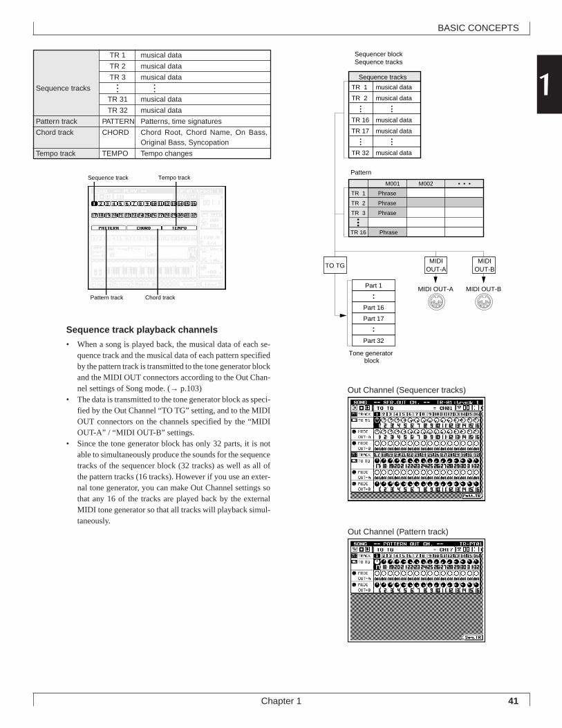
41
BASIC CONCEPTS
Chapter 1
1TR 1 musical data
TR 2 musical data
TR 3 musical data
Sequence tracks
TR 31 musical data
TR 32 musical data
Pattern track PATTERN Patterns, time signatures
Chord track CHORD Chord Root, Chord Name, On Bass,Original Bass, Syncopation
Tempo track TEMPO Tempo changes
Sequence track playback channels
• When a song is played back, the musical data of each se-quence track and the musical data of each pattern specifiedby the pattern track is transmitted to the tone generator blockand the MIDI OUT connectors according to the Out Chan-nel settings of Song mode. (→ p.103)
• The data is transmitted to the tone generator block as speci-fied by the Out Channel “TO TG” setting, and to the MIDIOUT connectors on the channels specified by the “MIDIOUT-A” / “MIDI OUT-B” settings.
• Since the tone generator block has only 32 parts, it is notable to simultaneously produce the sounds for the sequencetracks of the sequencer block (32 tracks) as well as all ofthe pattern tracks (16 tracks). However if you use an exter-nal tone generator, you can make Out Channel settings sothat any 16 of the tracks are played back by the externalMIDI tone generator so that all tracks will playback simul-taneously.
Sequence track
Pattern track
Tempo track
Chord track
TR 1 musical data
TR 2 musical data
TR 16 musical data
TR 17 musical data
TR 32 musical data
Sequence tracks
Sequencer blockSequence tracks
TR 1 Phrase
TR 2 Phrase
TR 3 Phrase
TR 16 Phrase
M001 M002 • • •
Part 1
Part 16
Part 17
Part 32
MIDIOUT-A
MIDIOUT-B
MIDI OUT-A MIDI OUT-B
TO TG
Pattern
Tone generator block
Out Channel (Sequencer tracks)
Out Channel (Pattern track)
• • •
• • •
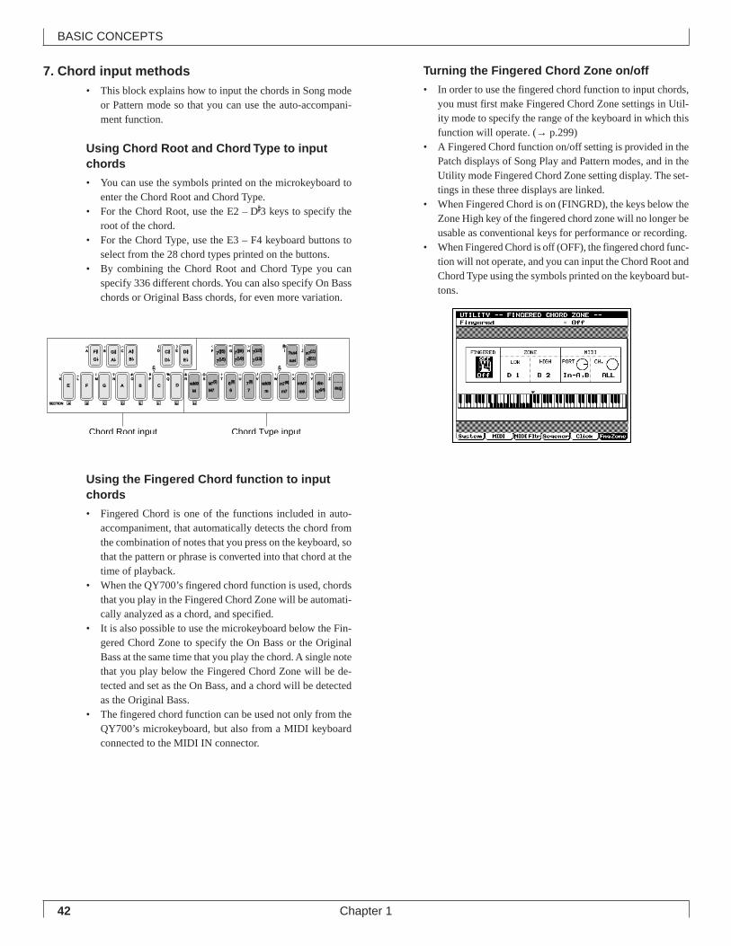
42
BASIC CONCEPTS
Chapter 1
7. Chord input methods• This block explains how to input the chords in Song mode
or Pattern mode so that you can use the auto-accompani-ment function.
Using Chord Root and Chord Type to inputchords
• You can use the symbols printed on the microkeyboard toenter the Chord Root and Chord Type.
• For the Chord Root, use the E2 – D#3 keys to specify the
root of the chord.• For the Chord Type, use the E3 – F4 keyboard buttons to
select from the 28 chord types printed on the buttons.• By combining the Chord Root and Chord Type you can
specify 336 different chords. You can also specify On Basschords or Original Bass chords, for even more variation.
Using the Fingered Chord function to inputchords
• Fingered Chord is one of the functions included in auto-accompaniment, that automatically detects the chord fromthe combination of notes that you press on the keyboard, sothat the pattern or phrase is converted into that chord at thetime of playback.
• When the QY700’s fingered chord function is used, chordsthat you play in the Fingered Chord Zone will be automati-cally analyzed as a chord, and specified.
• It is also possible to use the microkeyboard below the Fin-gered Chord Zone to specify the On Bass or the OriginalBass at the same time that you play the chord. A single notethat you play below the Fingered Chord Zone will be de-tected and set as the On Bass, and a chord will be detectedas the Original Bass.
• The fingered chord function can be used not only from theQY700’s microkeyboard, but also from a MIDI keyboardconnected to the MIDI IN connector.
Turning the Fingered Chord Zone on/off
• In order to use the fingered chord function to input chords,you must first make Fingered Chord Zone settings in Util-ity mode to specify the range of the keyboard in which thisfunction will operate. (→ p.299)
• A Fingered Chord function on/off setting is provided in thePatch displays of Song Play and Pattern modes, and in theUtility mode Fingered Chord Zone setting display. The set-tings in these three displays are linked.
• When Fingered Chord is on (FINGRD), the keys below theZone High key of the fingered chord zone will no longer beusable as conventional keys for performance or recording.
• When Fingered Chord is off (OFF), the fingered chord func-tion will not operate, and you can input the Chord Root andChord Type using the symbols printed on the keyboard but-tons.
F #
E F G A B C DM
add9
M7
add9
a
m
mM7
m6
c
C # D #7(#5)
7( b5)
7(#9) 7sus4
sus4
SECTION A
G b D b E b 7( b9)
m7(b5)
M7(9)
6
6(9)
7
7(9) m7(9)
m7
dimZWV
/
HGF
UTSRQPO#
N
CBA
?MLK
_ ! S % &
E)
D(
_
YX
aug
7( b13)
7(13) 7(#11)
JI m7(11)
c
G #A b
A #B b
B C D E F G H
Chord Root input Chord Type input
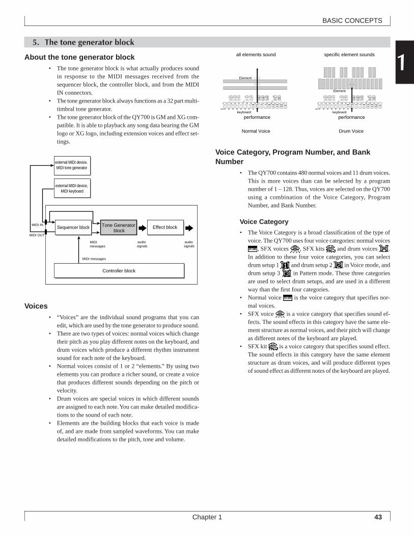
43
BASIC CONCEPTS
Chapter 1
15. The tone generator block
About the tone generator block• The tone generator block is what actually produces sound
in response to the MIDI messages received from thesequencer block, the controller block, and from the MIDIIN connectors.
• The tone generator block always functions as a 32 part multi-timbral tone generator.
• The tone generator block of the QY700 is GM and XG com-patible. It is able to playback any song data bearing the GMlogo or XG logo, including extension voices and effect set-tings.
Voices• “Voices” are the individual sound programs that you can
edit, which are used by the tone generator to produce sound.• There are two types of voices: normal voices which change
their pitch as you play different notes on the keyboard, anddrum voices which produce a different rhythm instrumentsound for each note of the keyboard.
• Normal voices consist of 1 or 2 “elements.” By using twoelements you can produce a richer sound, or create a voicethat produces different sounds depending on the pitch orvelocity.
• Drum voices are special voices in which different soundsare assigned to each note. You can make detailed modifica-tions to the sound of each note.
• Elements are the building blocks that each voice is madeof, and are made from sampled waveforms. You can makedetailed modifications to the pitch, tone and volume.
Voice Category, Program Number, and BankNumber
• The QY700 contains 480 normal voices and 11 drum voices.This is more voices than can be selected by a programnumber of 1 – 128. Thus, voices are selected on the QY700using a combination of the Voice Category, ProgramNumber, and Bank Number.
Voice Category
• The Voice Category is a broad classification of the type ofvoice. The QY700 uses four voice categories: normal voices
, SFX voices , SFX kits and drum voices .In addition to these four voice categories, you can selectdrum setup 1 and drum setup 2 in Voice mode, anddrum setup 3 in Pattern mode. These three categoriesare used to select drum setups, and are used in a differentway than the first four categories.
• Normal voice is the voice category that specifies nor-mal voices.
• SFX voice is a voice category that specifies sound ef-fects. The sound effects in this category have the same ele-ment structure as normal voices, and their pitch will changeas different notes of the keyboard are played.
• SFX kit is a voice category that specifies sound effect.The sound effects in this category have the same elementstructure as drum voices, and will produce different typesof sound effect as different notes of the keyboard are played.
audio signals
MIDI messages
audio signals
Controller block
MIDI IN
MIDI OUT
external MIDI device, MIDI keyboard
external MIDI device, MIDI tone generator
MIDI messages
Sequencer block Tone Generator block
Effect block
F #
E F G A B C DM
add9
M7
add9
a
m
mM7
m6
c
C # D #7(#5)
7( b5)
7(#9) 7sus4
sus4
SECTION A
G b D b E b 7( b9)
m7(b5)
M7(9)
6
6(9)
7
7(9) m7(9)
m7
dimZWV
/
HGF
UTSRQPO#
N
CBA
?MLK
_ ! S % &
E)
D(
_
YX
aug
7( b13)
7(13) 7(#11)
JI m7(11)
c
G #A b
A #B b
B C D E F G H
F #
E F G A B C DM
add9
M7
add9
a
m
mM7
m6
c
C # D #7(#5)
7( b5)
7(#9) 7sus4
sus4
SECTION A
G b D b E b 7( b9)
m7(b5)
M7(9)
6
6(9)
7
7(9) m7(9)
m7
dimZWV
/
HGF
UTSRQPO#
N
CBA
?MLK
_ ! S % &
E)
D(
_
YX
aug
7( b13)
7(13) 7(#11)
JI m7(11)
c
G #A b
A #B b
B C D E F G H
performance performance
all elements sound
Normal Voice
specific element sounds
Drum Voice
Element
Element
keyboard keyboard
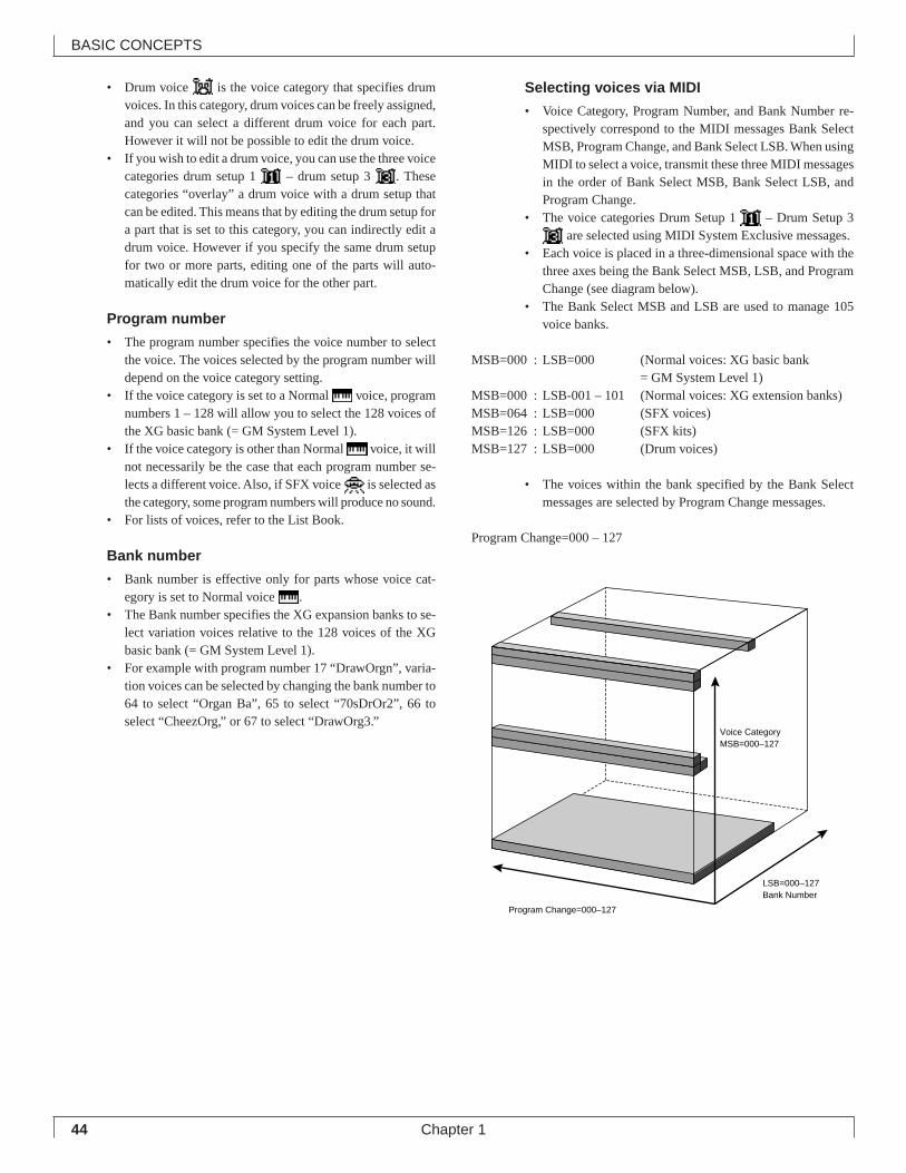
44
BASIC CONCEPTS
Chapter 1
• Drum voice is the voice category that specifies drumvoices. In this category, drum voices can be freely assigned,and you can select a different drum voice for each part.However it will not be possible to edit the drum voice.
• If you wish to edit a drum voice, you can use the three voicecategories drum setup 1 – drum setup 3 . Thesecategories “overlay” a drum voice with a drum setup thatcan be edited. This means that by editing the drum setup fora part that is set to this category, you can indirectly edit adrum voice. However if you specify the same drum setupfor two or more parts, editing one of the parts will auto-matically edit the drum voice for the other part.
Program number
• The program number specifies the voice number to selectthe voice. The voices selected by the program number willdepend on the voice category setting.
• If the voice category is set to a Normal voice, programnumbers 1 – 128 will allow you to select the 128 voices ofthe XG basic bank (= GM System Level 1).
• If the voice category is other than Normal voice, it willnot necessarily be the case that each program number se-lects a different voice. Also, if SFX voice is selected asthe category, some program numbers will produce no sound.
• For lists of voices, refer to the List Book.
Bank number
• Bank number is effective only for parts whose voice cat-egory is set to Normal voice .
• The Bank number specifies the XG expansion banks to se-lect variation voices relative to the 128 voices of the XGbasic bank (= GM System Level 1).
• For example with program number 17 “DrawOrgn”, varia-tion voices can be selected by changing the bank number to64 to select “Organ Ba”, 65 to select “70sDrOr2”, 66 toselect “CheezOrg,” or 67 to select “DrawOrg3.”
Selecting voices via MIDI
• Voice Category, Program Number, and Bank Number re-spectively correspond to the MIDI messages Bank SelectMSB, Program Change, and Bank Select LSB. When usingMIDI to select a voice, transmit these three MIDI messagesin the order of Bank Select MSB, Bank Select LSB, andProgram Change.
• The voice categories Drum Setup 1 – Drum Setup 3 are selected using MIDI System Exclusive messages.
• Each voice is placed in a three-dimensional space with thethree axes being the Bank Select MSB, LSB, and ProgramChange (see diagram below).
• The Bank Select MSB and LSB are used to manage 105voice banks.
MSB=000 : LSB=000 (Normal voices: XG basic bank= GM System Level 1)
MSB=000 : LSB-001 – 101 (Normal voices: XG extension banks)MSB=064 : LSB=000 (SFX voices)MSB=126 : LSB=000 (SFX kits)MSB=127 : LSB=000 (Drum voices)
• The voices within the bank specified by the Bank Selectmessages are selected by Program Change messages.
Program Change=000 – 127
Voice CategoryMSB=000–127
Program Change=000–127
LSB=000–127Bank Number
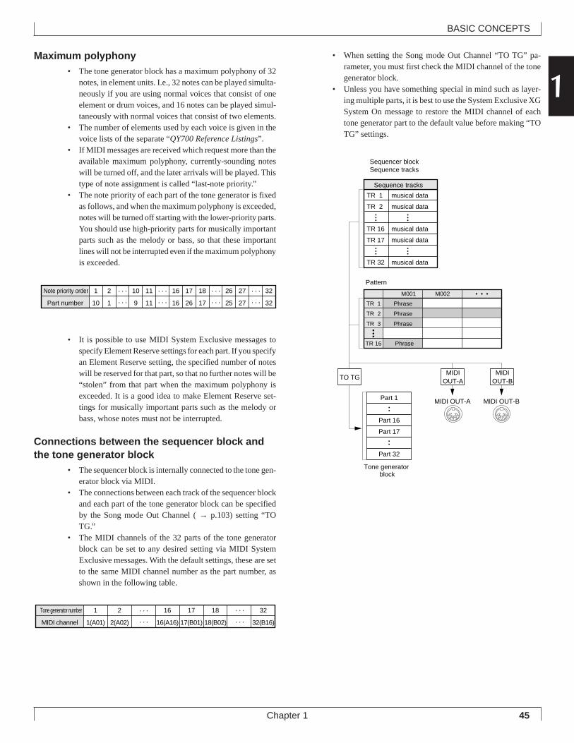
45
BASIC CONCEPTS
Chapter 1
1Maximum polyphony
• The tone generator block has a maximum polyphony of 32notes, in element units. I.e., 32 notes can be played simulta-neously if you are using normal voices that consist of oneelement or drum voices, and 16 notes can be played simul-taneously with normal voices that consist of two elements.
• The number of elements used by each voice is given in thevoice lists of the separate “QY700 Reference Listings”.
• If MIDI messages are received which request more than theavailable maximum polyphony, currently-sounding noteswill be turned off, and the later arrivals will be played. Thistype of note assignment is called “last-note priority.”
• The note priority of each part of the tone generator is fixedas follows, and when the maximum polyphony is exceeded,notes will be turned off starting with the lower-priority parts.You should use high-priority parts for musically importantparts such as the melody or bass, so that these importantlines will not be interrupted even if the maximum polyphonyis exceeded.
• It is possible to use MIDI System Exclusive messages tospecify Element Reserve settings for each part. If you specifyan Element Reserve setting, the specified number of noteswill be reserved for that part, so that no further notes will be“stolen” from that part when the maximum polyphony isexceeded. It is a good idea to make Element Reserve set-tings for musically important parts such as the melody orbass, whose notes must not be interrupted.
Connections between the sequencer block andthe tone generator block
• The sequencer block is internally connected to the tone gen-erator block via MIDI.
• The connections between each track of the sequencer blockand each part of the tone generator block can be specifiedby the Song mode Out Channel ( → p.103) setting “TOTG.”
• The MIDI channels of the 32 parts of the tone generatorblock can be set to any desired setting via MIDI SystemExclusive messages. With the default settings, these are setto the same MIDI channel number as the part number, asshown in the following table.
• When setting the Song mode Out Channel “TO TG” pa-rameter, you must first check the MIDI channel of the tonegenerator block.
• Unless you have something special in mind such as layer-ing multiple parts, it is best to use the System Exclusive XGSystem On message to restore the MIDI channel of eachtone generator part to the default value before making “TOTG” settings.
TR 1 musical data
TR 2 musical data
TR 16 musical data
TR 17 musical data
TR 32 musical data
Sequence tracks
Sequencer blockSequence tracks
TR 1 Phrase
TR 2 Phrase
TR 3 Phrase
TR 16 Phrase
M001 M002 • • •
Part 1
Part 16
Part 17
Part 32
MIDIOUT-A
MIDIOUT-B
MIDI OUT-A MIDI OUT-B
TO TG
Pattern
Tone generator block
Note priority order 1 2 10 11 16 17 18 26 27 32
Part number 10 1 9 11 16 26 17 25 27 32
Tone generator number 1 2 16 17 18 32
MIDI channel 1(A01) 2(A02) 16(A16) 17(B01) 18(B02) 32(B16)
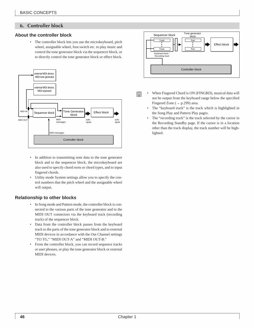
46
BASIC CONCEPTS
Chapter 1
audio signals
MIDI messages
audio signals
Controller block
MIDI IN
MIDI OUT
external MIDI device, MIDI tone generator
external MIDI device,MIDI keyboard
MIDI messages
Sequencer block Tone Generator block
Effect block
6. Controller block
About the controller block• The controller block lets you use the microkeyboard, pitch
wheel, assignable wheel, foot switch etc. to play music andcontrol the tone generator block via the sequencer block, orto directly control the tone generator block or effect block.
• In addition to transmitting note data to the tone generatorblock and to the sequencer block, the microkeyboard arealso used to specify chord roots or chord types, and to inputfingered chords.
• Utility mode System settings allow you to specify the con-trol numbers that the pitch wheel and the assignable wheelwill output.
Relationship to other blocks• In Song mode and Pattern mode, the controller block is con-
nected to the various parts of the tone generator and to theMIDI OUT connectors via the keyboard track (recordingtrack) of the sequencer block.
• Data from the controller block passes from the keyboardtrack to the parts of the tone generator block and to externalMIDI devices in accordance with the Out Channel settings“TO TG,” “MIDI OUT-A” and “MIDI OUT-B.”
• From the controller block, you can record sequence tracksor user phrases, or play the tone generator block or externalMIDI devices.
• When Fingered Chord is ON (FINGRD), musical data willnot be output from the keyboard range below the specifiedFingered Zone (→ p.299) area.
• The “keyboard track” is the track which is highlighted inthe Song Play and Pattern Play pages.
• The “recording track” is the track selected by the cursor inthe Recording Standby page. If the cursor is in a locationother than the track display, the track number will be high-lighted.
Keyboard track / Recording track
Controller block
Part
Tone generator block
Effect block
Part
Track
Sequencer block
Track
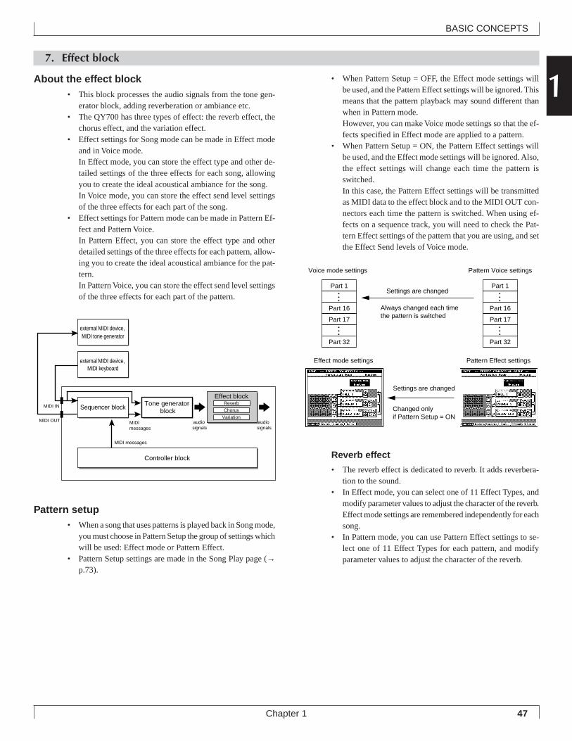
47
BASIC CONCEPTS
Chapter 1
17. Effect block
About the effect block• This block processes the audio signals from the tone gen-
erator block, adding reverberation or ambiance etc.• The QY700 has three types of effect: the reverb effect, the
chorus effect, and the variation effect.• Effect settings for Song mode can be made in Effect mode
and in Voice mode.In Effect mode, you can store the effect type and other de-tailed settings of the three effects for each song, allowingyou to create the ideal acoustical ambiance for the song.In Voice mode, you can store the effect send level settingsof the three effects for each part of the song.
• Effect settings for Pattern mode can be made in Pattern Ef-fect and Pattern Voice.In Pattern Effect, you can store the effect type and otherdetailed settings of the three effects for each pattern, allow-ing you to create the ideal acoustical ambiance for the pat-tern.In Pattern Voice, you can store the effect send level settingsof the three effects for each part of the pattern.
Pattern setup• When a song that uses patterns is played back in Song mode,
you must choose in Pattern Setup the group of settings whichwill be used: Effect mode or Pattern Effect.
• Pattern Setup settings are made in the Song Play page (→p.73).
• When Pattern Setup = OFF, the Effect mode settings willbe used, and the Pattern Effect settings will be ignored. Thismeans that the pattern playback may sound different thanwhen in Pattern mode.However, you can make Voice mode settings so that the ef-fects specified in Effect mode are applied to a pattern.
• When Pattern Setup = ON, the Pattern Effect settings willbe used, and the Effect mode settings will be ignored. Also,the effect settings will change each time the pattern isswitched.In this case, the Pattern Effect settings will be transmittedas MIDI data to the effect block and to the MIDI OUT con-nectors each time the pattern is switched. When using ef-fects on a sequence track, you will need to check the Pat-tern Effect settings of the pattern that you are using, and setthe Effect Send levels of Voice mode.
Reverb effect
• The reverb effect is dedicated to reverb. It adds reverbera-tion to the sound.
• In Effect mode, you can select one of 11 Effect Types, andmodify parameter values to adjust the character of the reverb.Effect mode settings are remembered independently for eachsong.
• In Pattern mode, you can use Pattern Effect settings to se-lect one of 11 Effect Types for each pattern, and modifyparameter values to adjust the character of the reverb.
audio signals
MIDI messages
MIDI messages
MIDI IN
MIDI OUT audio signals
Controller block
Tone generator blockSequencer block
external MIDI device, MIDI tone generator
Effect blockReverb
Chorus
Variation
external MIDI device, MIDI keyboard
Part 1
Part 16
Part 17
Part 32
Part 1
Part 16
Part 17
Part 32
Voice mode settings Pattern Voice settings
Settings are changed
Settings are changed
Always changed each time the pattern is switched
Changed only if Pattern Setup = ON
Effect mode settings Pattern Effect settings
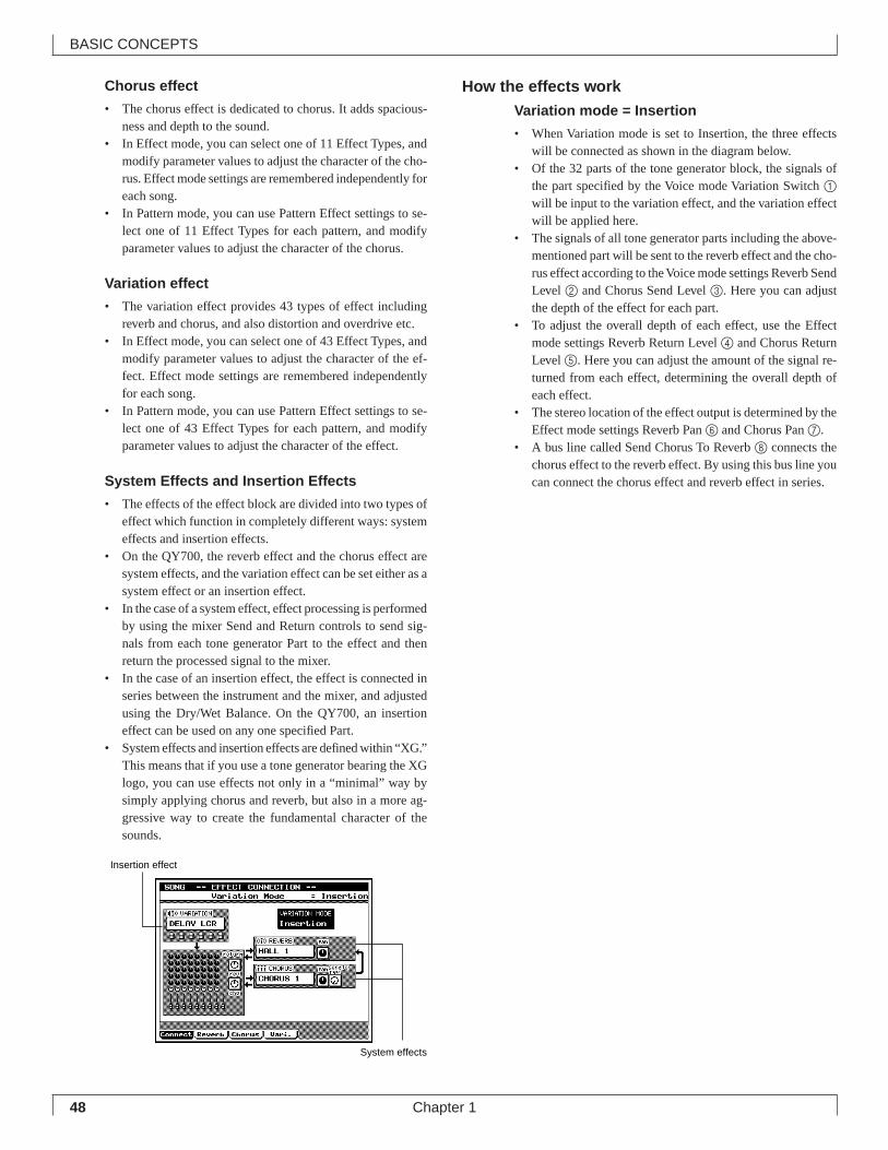
48
BASIC CONCEPTS
Chapter 1
Insertion effect
System effects
Chorus effect
• The chorus effect is dedicated to chorus. It adds spacious-ness and depth to the sound.
• In Effect mode, you can select one of 11 Effect Types, andmodify parameter values to adjust the character of the cho-rus. Effect mode settings are remembered independently foreach song.
• In Pattern mode, you can use Pattern Effect settings to se-lect one of 11 Effect Types for each pattern, and modifyparameter values to adjust the character of the chorus.
Variation effect
• The variation effect provides 43 types of effect includingreverb and chorus, and also distortion and overdrive etc.
• In Effect mode, you can select one of 43 Effect Types, andmodify parameter values to adjust the character of the ef-fect. Effect mode settings are remembered independentlyfor each song.
• In Pattern mode, you can use Pattern Effect settings to se-lect one of 43 Effect Types for each pattern, and modifyparameter values to adjust the character of the effect.
System Effects and Insertion Effects
• The effects of the effect block are divided into two types ofeffect which function in completely different ways: systemeffects and insertion effects.
• On the QY700, the reverb effect and the chorus effect aresystem effects, and the variation effect can be set either as asystem effect or an insertion effect.
• In the case of a system effect, effect processing is performedby using the mixer Send and Return controls to send sig-nals from each tone generator Part to the effect and thenreturn the processed signal to the mixer.
• In the case of an insertion effect, the effect is connected inseries between the instrument and the mixer, and adjustedusing the Dry/Wet Balance. On the QY700, an insertioneffect can be used on any one specified Part.
• System effects and insertion effects are defined within “XG.”This means that if you use a tone generator bearing the XGlogo, you can use effects not only in a “minimal” way bysimply applying chorus and reverb, but also in a more ag-gressive way to create the fundamental character of thesounds.
How the effects workVariation mode = Insertion
• When Variation mode is set to Insertion, the three effectswill be connected as shown in the diagram below.
• Of the 32 parts of the tone generator block, the signals ofthe part specified by the Voice mode Variation Switch 1
will be input to the variation effect, and the variation effectwill be applied here.
• The signals of all tone generator parts including the above-mentioned part will be sent to the reverb effect and the cho-rus effect according to the Voice mode settings Reverb SendLevel 2 and Chorus Send Level 3. Here you can adjustthe depth of the effect for each part.
• To adjust the overall depth of each effect, use the Effectmode settings Reverb Return Level 4 and Chorus ReturnLevel 5. Here you can adjust the amount of the signal re-turned from each effect, determining the overall depth ofeach effect.
• The stereo location of the effect output is determined by theEffect mode settings Reverb Pan 6 and Chorus Pan 7.
• A bus line called Send Chorus To Reverb 8 connects thechorus effect to the reverb effect. By using this bus line youcan connect the chorus effect and reverb effect in series.
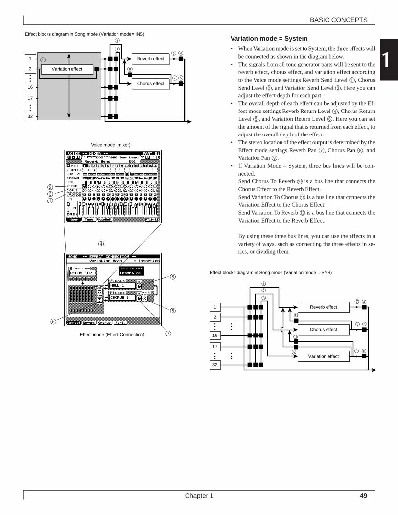
49
BASIC CONCEPTS
Chapter 1
1Variation mode = System
• When Variation mode is set to System, the three effects willbe connected as shown in the diagram below.
• The signals from all tone generator parts will be sent to thereverb effect, chorus effect, and variation effect accordingto the Voice mode settings Reverb Send Level 1, ChorusSend Level 2, and Variation Send Level 3. Here you canadjust the effect depth for each part.
• The overall depth of each effect can be adjusted by the Ef-fect mode settings Reverb Return Level 4, Chorus ReturnLevel 5, and Variation Return Level 6. Here you can setthe amount of the signal that is returned from each effect, toadjust the overall depth of the effect.
• The stereo location of the effect output is determined by theEffect mode settings Reverb Pan 7, Chorus Pan 8, andVariation Pan 9.
• If Variation Mode = System, three bus lines will be con-nected.Send Chorus To Reverb 0 is a bus line that connects theChorus Effect to the Reverb Effect.Send Variation To Chorus A is a bus line that connects theVariation Effect to the Chorus Effect.Send Variation To Reverb B is a bus line that connects theVariation Effect to the Reverb Effect.
By using these three bus lines, you can use the effects in avariety of ways, such as connecting the three effects in se-ries, or dividing them.
Effect blocks diagram in Song mode (Variation mode= INS)
1
16
2
Reverb effect
Chorus effect
1
8
46
57
3
2
17
32
Variation effect
Effect blocks diagram in Song mode (Variation mode = SYS)
1
16
2 0
5
A
B 6
7
917
32
Chorus effect
Reverb effect
Variation effect
1
2
34
8
132
Voice mode (mixer)
Effect mode (Effect Connection)
4
5
6
7
8
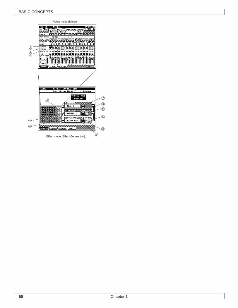
50
BASIC CONCEPTS
Chapter 1
321
Voice mode (Mixer)
Effect mode (Effect Connection)
4
5
6
7
8
9
0
A
B
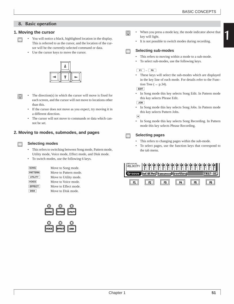
51
BASIC CONCEPTS
Chapter 1
18. Basic operation
• When you press a mode key, the mode indicator above thatkey will light.
• It is not possible to switch modes during recording.
Selecting sub-modes
• This refers to moving within a mode to a sub-mode.• To select sub-modes, use the following keys.
1 –6• These keys will select the sub-modes which are displayed
in the key line of each mode. For details refer to the Func-tion Tree (→ p.34).
e
• In Song mode this key selects Song Edit. In Pattern modethis key selects Phrase Edit.
j
• In Song mode this key selects Song Jobs. In Pattern modethis key selects Pattern Jobs.
e
• In Song mode this key selects Song Recording. In Patternmode this key selects Phrase Recording.
Selecting pages
• This refers to changing pages within the sub-mode.• To select pages, use the function keys that correspond to
the tab menu.
1. Moving the cursor• You will notice a black, highlighted location in the display.
This is referred to as the cursor, and the location of the cur-sor will be the currently-selected command or data.
• Use the cursor keys to move the cursor.
• The direction(s) in which the cursor will move is fixed foreach screen, and the cursor will not move to locations otherthan this.
• If the cursor does not move as you expect, try moving it ina different direction.
• The cursor will not move to commands or data which can-not be set.
2. Moving to modes, submodes, and pages
Selecting modes
• This refers to switching between Song mode, Pattern mode,Utility mode, Voice mode, Effect mode, and Disk mode.
• To switch modes, use the following 6 keys.
s Move to Song mode.p Move to Pattern mode.u Move to Utility mode.v Move to Voice mode.e Move to Effect mode.d Move to Disk mode.
VOICE EFFECT DISK
SONG PATTERN UTILITY
F1 F2 F3 F4 F5 F6
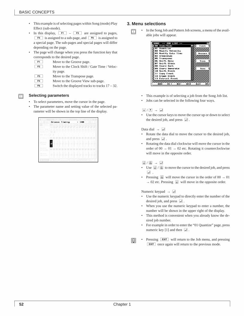
52
BASIC CONCEPTS
Chapter 1
• This example is of selecting pages within Song (mode) PlayEffect (sub-mode).
• In this display, 1 – 3 are assigned to pages,4 is assigned to a sub-page, and 6 is assigned toa special page. The sub-pages and special pages will differdepending on the page.
• The page will change when you press the function key thatcorresponds to the desired page.1 Move to the Groove page.2 Move to the Clock Shift / Gate Time / Veloc-
ity page.3 Move to the Transpose page.4 Move to the Groove View sub-page.6 Switch the displayed tracks to tracks 17 – 32.
Selecting parameters
• To select parameters, move the cursor in the page.• The parameter name and setting value of the selected pa-
rameter will be shown in the top line of the display.
3. Menu selections• In the Song Job and Pattern Job screens, a menu of the avail-
able jobs will appear.
• This example is of selecting a job from the Song Job list.• Jobs can be selected in the following four ways.
u/d → e• Use the cursor keys to move the cursor up or down to select
the desired job, and press e.
Data dial → e• Rotate the data dial to move the cursor to the desired job,
and press e.• Rotating the data dial clockwise will move the cursor in the
order of 00 → 01 → 02 etc. Rotating it counterclockwisewill move in the opposite order.
n/y → e• Use n/y to move the cursor to the desired job, and press
e .• Pressing y will move the cursor in the order of 00 → 01
→ 02 etc. Pressing n will move in the opposite order.
Numeric keypad → e• Use the numeric keypad to directly enter the number of the
desired job, and press e.• When you use the numeric keypad to enter a number, the
number will be shown in the upper right of the display.• This method is convenient when you already know the de-
sired job number.• For example in order to enter the “01 Quantize” page, press
numeric key [1] and then e.
• Pressing e will return to the Job menu, and pressinge once again will return to the previous mode.
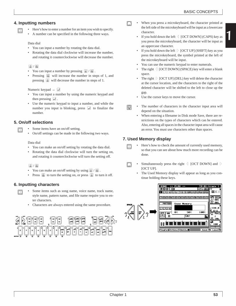
53
BASIC CONCEPTS
Chapter 1
14. Inputting numbers
• Here’s how to enter a number for an item you wish to specify.• A number can be specified in the following three ways.
Data dial• You can input a number by rotating the data dial.• Rotating the data dial clockwise will increase the number,
and rotating it counterclockwise will decrease the number.
n/y• You can input a number by pressing n/y.• Pressing y will increase the number in steps of 1, and
pressing n will decrease the number in steps of 1.
Numeric keypad → e• You can input a number by using the numeric keypad and
then pressing e.• Use the numeric keypad to input a number, and while the
number you input is blinking, press e to finalize thenumber.
5. On/off selections• Some items have an on/off setting.• On/off settings can be made in the following two ways.
Data dial• You can make an on/off setting by rotating the data dial.• Rotating the data dial clockwise will turn the setting on,
and rotating it counterclockwise will turn the setting off.
n/y• You can make an on/off setting by usingn/y.• Press y to turn the setting on, or press n to turn it off.
6. Inputting characters• Some items such as song name, voice name, track name,
style name, pattern name, and file name require you to en-ter characters.
• Characters are always entered using the same procedure.
• When you press a microkeyboard, the character printed atthe left side of the microkeyboard will be input as a lowercasecharacter.
• If you hold down the left d [OCT DOWN] (CAPS) key asyou press the microkeyboard, the character will be input asan uppercase character.
• If you hold down the left u [OCT UP] (SHIFT) key as youpress the microkeyboard, the symbol printed at the left ofthe microkeyboard will be input.
• You can use the numeric keypad to enter numerals.• The right d [OCT DOWN] (SPACE) key will enter a blank
space.• The right u [OCT UP] (DEL) key will delete the character
at the cursor location, and the characters to the right of thedeleted character will be shifted to the left to close up thegap.
• Use the cursor keys to move the cursor.
• The number of characters in the character input area willdepend on the situation.
• When entering a filename in Disk mode Save, there are re-strictions on the types of characters which can be entered.Also, entering all spaces in the character input area will causean error. You must use characters other than spaces.
7. Used Memory display• Here’s how to check the amount of currently used memory,
so that you can see about how much more recording can bedone.
• Simultaneously press the right d [OCT DOWN] and u[OCT UP].
• The Used Memory display will appear as long as you con-tinue holding these keys.
OCTDOWN
OCTUP
OCTDOWN
OCTUP
ONBASS
F #
E F G A B C DM
add9
M7
add9
a
m
mM7
m6
c
C # D #7(#5)
7( b5)
7(#9) 7sus4
sus4
SECTION A
G b D b E b 7( b9)
m7(b5)
M7(9)
6
6(9)
7
7(9) m7(9)
m7
dimZWV
/
HGF
UTSRQPO#
N
CBA
?MLK
_ ! S % &
E)
D(
_
YX
aug
7( b13)
7(13) 7(#11)
JI m7(11)
ORGBASS
CAPS SHIFT SPACE
3
DEL
c
G #A b
A #B b 3
B C D E F G H
OCTDOWN
OCTUP
SPACE
3
DEL
3
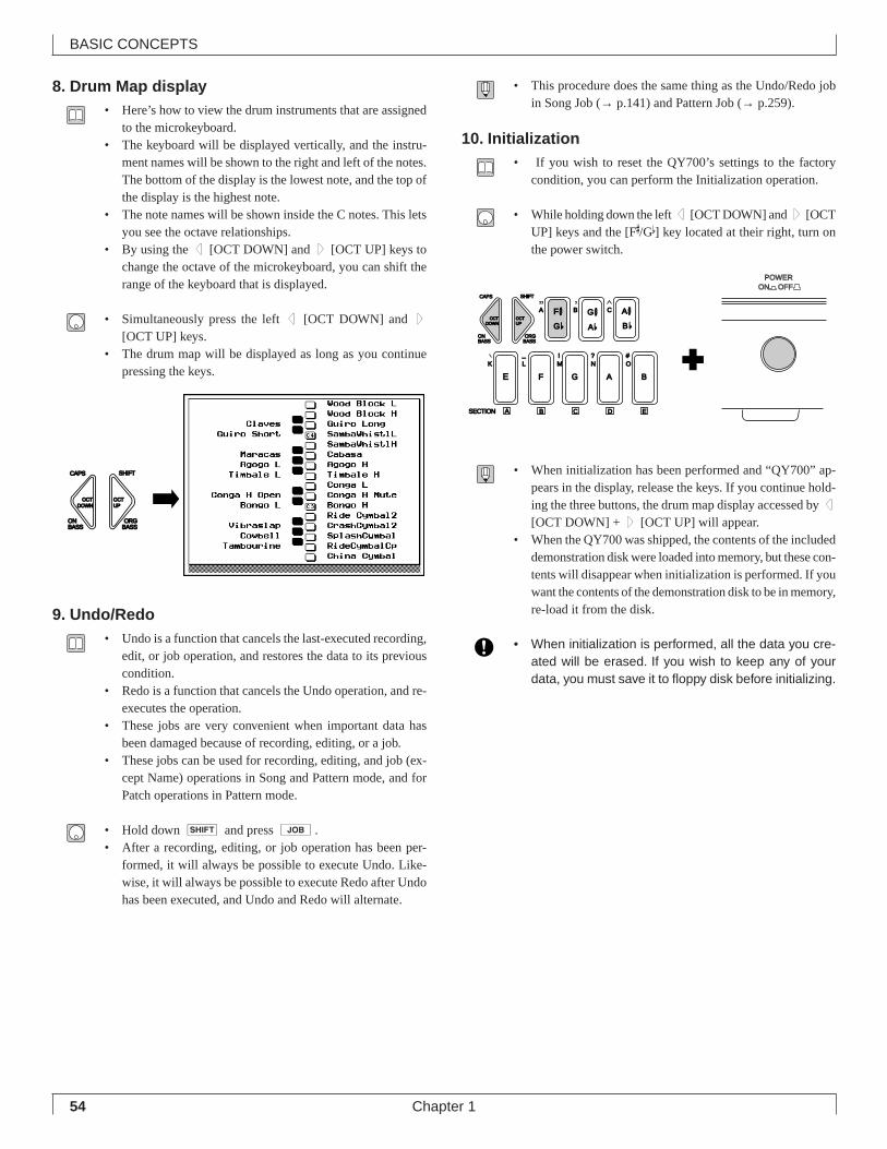
54
BASIC CONCEPTS
Chapter 1
8. Drum Map display• Here’s how to view the drum instruments that are assigned
to the microkeyboard.• The keyboard will be displayed vertically, and the instru-
ment names will be shown to the right and left of the notes.The bottom of the display is the lowest note, and the top ofthe display is the highest note.
• The note names will be shown inside the C notes. This letsyou see the octave relationships.
• By using the d [OCT DOWN] and u [OCT UP] keys tochange the octave of the microkeyboard, you can shift therange of the keyboard that is displayed.
• Simultaneously press the left d [OCT DOWN] and u[OCT UP] keys.
• The drum map will be displayed as long as you continuepressing the keys.
9. Undo/Redo• Undo is a function that cancels the last-executed recording,
edit, or job operation, and restores the data to its previouscondition.
• Redo is a function that cancels the Undo operation, and re-executes the operation.
• These jobs are very convenient when important data hasbeen damaged because of recording, editing, or a job.
• These jobs can be used for recording, editing, and job (ex-cept Name) operations in Song and Pattern mode, and forPatch operations in Pattern mode.
• Hold down s and press j.• After a recording, editing, or job operation has been per-
formed, it will always be possible to execute Undo. Like-wise, it will always be possible to execute Redo after Undohas been executed, and Undo and Redo will alternate.
• This procedure does the same thing as the Undo/Redo jobin Song Job (→ p.141) and Pattern Job (→ p.259).
10. Initialization• If you wish to reset the QY700’s settings to the factory
condition, you can perform the Initialization operation.
• While holding down the left d [OCT DOWN] and u [OCTUP] keys and the [F#/Gb] key located at their right, turn onthe power switch.
• When initialization has been performed and “QY700” ap-pears in the display, release the keys. If you continue hold-ing the three buttons, the drum map display accessed by d
[OCT DOWN] + u [OCT UP] will appear.• When the QY700 was shipped, the contents of the included
demonstration disk were loaded into memory, but these con-tents will disappear when initialization is performed. If youwant the contents of the demonstration disk to be in memory,re-load it from the disk.
• When initialization is performed, all the data you cre-ated will be erased. If you wish to keep any of yourdata, you must save it to floppy disk before initializing.
OCTDOWN
OCTUP
ONBASS
ORGBASS
CAPS SHIFT
OCTDOWN
OCTUP
ONBASS
F #
E F G A B
SECTION A
G b
O#
N
CBA
?MLK
_ !
ORGBASS
CAPS SHIFT
G #A b
A #B b
B C D E
POWERON OFF
55
BASIC CONCEPTS
Chapter 1
111. Other key operations
Here are some convenient key operations that you should know.
Auto Repeat function
• The cursor keys, n/y, and r/f will Auto Repeat.• If you continue holding them, the value or item being con-
trolled by the key will change continuously.
r/f
• In Song mode or Pattern mode, these keys will rewind/fast-forward measures regardless of the cursor location.
s
• s + data dial or s + n/y will increase/de-crease common parameters in the display by the same value.
• s + numeric keypad → e will specify the same valuefor common parameters in the display.
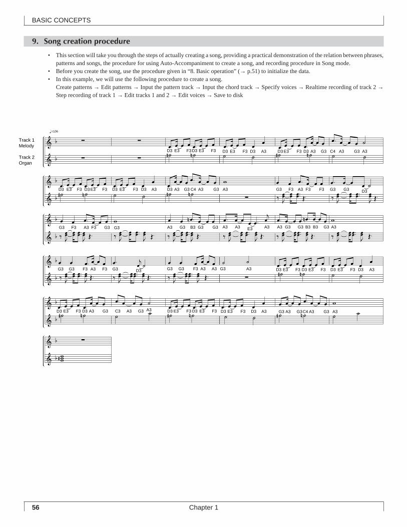
56
BASIC CONCEPTS
Chapter 1
9. Song creation procedure
• This section will take you through the steps of actually creating a song, providing a practical demonstration of the relation between phrases,patterns and songs, the procedure for using Auto-Accompaniment to create a song, and recording procedure in Song mode.
• Before you create the song, use the procedure given in “8. Basic operation” (→ p.51) to initialize the data.• In this example, we will use the following procedure to create a song.
Create patterns → Edit patterns → Input the pattern track → Input the chord track → Specify voices → Realtime recording of track 2 →Step recording of track 1 → Edit tracks 1 and 2 → Edit voices → Save to disk
=106
Track 1Melody
Track 2Organ
D3 E3 F3D3 E3 F3 D3 E3
Î Î ÎG3 G3 F3 A3 D3 G3 G3 F3 A3 A3G3F3
E3 D3 E3 F3 D3 A3 G3 A3 G3C4 A3 G3 A3F3 D3 A3 G3 C3 A3 G3 D3 E3 F3 D3 E3 F3A3
G3 A3 E3D3 F3 D3 E3 F3 D3 E3 F3 D3 A3
Î Î ÎA3 A3 E3 A3 A3 G3 G3 G3B3B3 A3
F3 D3 A3 D3 E3 F3 D3
F3 D3
A3
A3 Î ÎA3 G3 F3 A3 F3 F3 G3 G3 D3D3 A3D3 E3 F3 E3D3 F3 D3 E3 G3 C4 A3 G3
G3 C4 A3 G3 A3
Î ÎÎG3 F3 A3 F3 G3 G3 A3 G3 B3 G3 G3
D3

57
BASIC CONCEPTS
Chapter 1
1Create patterns
Patterns to be created
Style 01, Section A
"intro"
Style 01, Section B
"normal1"
Style 01, Section C
"normal2"
Style 01, Section D
"fill1"
Style 01, Section E
"fill2"
Style 01, Section F
"ending"
Pattern creation procedure• The procedure for creating a pattern will be explained as
we create the Style 01 Section A “intro” pattern.
1. Enter Pattern mode.• Press p to enter Pattern mode.
2. Select a pattern.(1) Move the cursor to the Style number or Section (→ p.202).
(2) Use the data dial, n/y or the numeric keypad → e toselect Style 01 and Section A.
3. Specify the number of measures in the pattern.(1) Press d [D1] twice to move the cursor to the number
of measures.(2) Use the data dial, n/y, or numeric keypad → e to set
the number of measures to 02.
4. Set the Section Connection (→ p.202).(1) Move the cursor to Section Connection.(2) Use the jog dial or n/y to set the Section Connection to
C.
5. Move the cursor to the location where the phrase orrest will be entered.
• Refer to the diagram for the pattern you are creating, tocheck the location where the phrase will be placed.
• First, move the cursor to M002 of track 1.
SHIFT F1 F2 F3 F4 F5 F6 SHIFT EXIT
Section connection
Style number Section Measure number [D1]
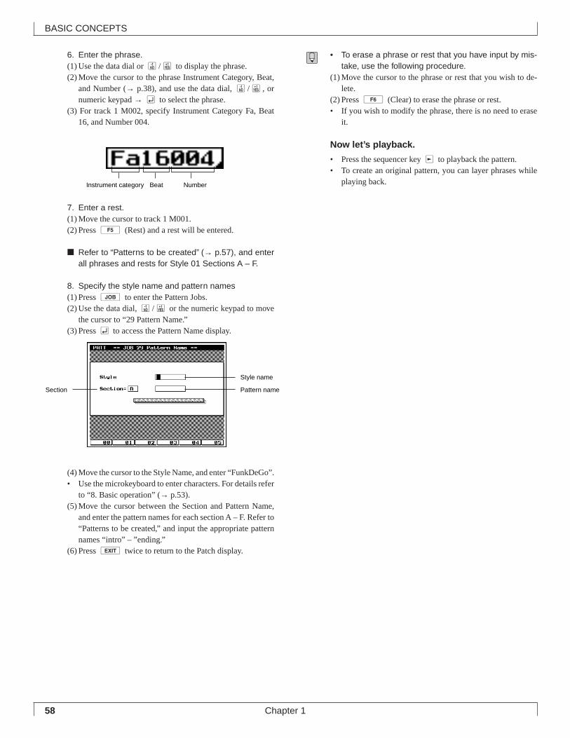
58
BASIC CONCEPTS
Chapter 1
6. Enter the phrase.(1) Use the data dial or n/y to display the phrase.(2) Move the cursor to the phrase Instrument Category, Beat,
and Number (→ p.38), and use the data dial, n/y, ornumeric keypad → e to select the phrase.
(3) For track 1 M002, specify Instrument Category Fa, Beat16, and Number 004.
7. Enter a rest.(1) Move the cursor to track 1 M001.(2) Press 5 (Rest) and a rest will be entered.
■ Refer to “Patterns to be created” (→ p.57), and enterall phrases and rests for Style 01 Sections A – F.
8. Specify the style name and pattern names(1) Press j to enter the Pattern Jobs.(2) Use the data dial, n/y or the numeric keypad to move
the cursor to “29 Pattern Name.”(3) Press e to access the Pattern Name display.
(4) Move the cursor to the Style Name, and enter “FunkDeGo”.• Use the microkeyboard to enter characters. For details refer
to “8. Basic operation” (→ p.53).(5) Move the cursor between the Section and Pattern Name,
and enter the pattern names for each section A – F. Refer to“Patterns to be created,” and input the appropriate patternnames “intro” – ”ending.”
(6) Press e twice to return to the Patch display.
• To erase a phrase or rest that you have input by mis-take, use the following procedure.
(1) Move the cursor to the phrase or rest that you wish to de-lete.
(2) Press 6 (Clear) to erase the phrase or rest.• If you wish to modify the phrase, there is no need to erase
it.
Now let’s playback.
• Press the sequencer key r to playback the pattern.• To create an original pattern, you can layer phrases while
playing back.Instrument category Beat Number
Style name
Pattern nameSection
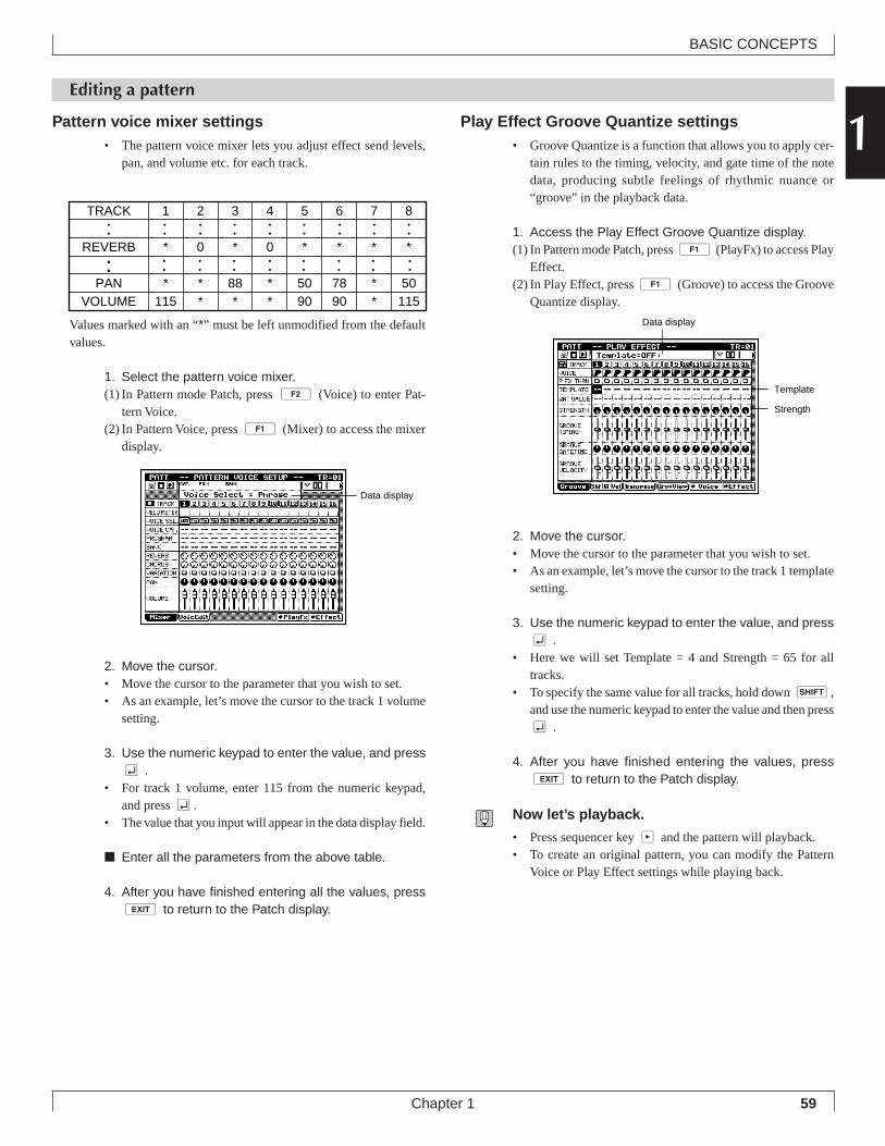
59
BASIC CONCEPTS
Chapter 1
1Editing a pattern
Pattern voice mixer settings• The pattern voice mixer lets you adjust effect send levels,
pan, and volume etc. for each track.
Values marked with an “*” must be left unmodified from the defaultvalues.
1. Select the pattern voice mixer.(1) In Pattern mode Patch, press 2 (Voice) to enter Pat-
tern Voice.(2) In Pattern Voice, press 1 (Mixer) to access the mixer
display.
2. Move the cursor.• Move the cursor to the parameter that you wish to set.• As an example, let’s move the cursor to the track 1 volume
setting.
3. Use the numeric keypad to enter the value, and presse .
• For track 1 volume, enter 115 from the numeric keypad,and press e.
• The value that you input will appear in the data display field.
■ Enter all the parameters from the above table.
4. After you have finished entering all the values, presse to return to the Patch display.
Play Effect Groove Quantize settings• Groove Quantize is a function that allows you to apply cer-
tain rules to the timing, velocity, and gate time of the notedata, producing subtle feelings of rhythmic nuance or“groove” in the playback data.
1. Access the Play Effect Groove Quantize display.(1) In Pattern mode Patch, press 1 (PlayFx) to access Play
Effect.(2) In Play Effect, press 1 (Groove) to access the Groove
Quantize display.
2. Move the cursor.• Move the cursor to the parameter that you wish to set.• As an example, let’s move the cursor to the track 1 template
setting.
3. Use the numeric keypad to enter the value, and presse .
• Here we will set Template = 4 and Strength = 65 for alltracks.
• To specify the same value for all tracks, hold down s,and use the numeric keypad to enter the value and then presse .
4. After you have finished entering the values, presse to return to the Patch display.
Now let’s playback.
• Press sequencer key p and the pattern will playback.• To create an original pattern, you can modify the Pattern
Voice or Play Effect settings while playing back.
Data display
Template
Strength
TRACK 1 2 3 4 5 6 7 8
REVERB * 0 * 0 * * * *
PAN * * 88 * 50 78 * 50VOLUME 115 * * * 90 90 * 115
••
••
••
••
••
••
••
••
••
••
••
••
••
••
••••
••
••
••
••
••
Data display
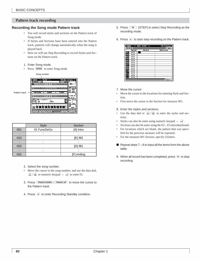
60
BASIC CONCEPTS
Chapter 1
Pattern track recording
Style Section001 01 FuncDeGo [A] intro
: : :010 [E] fill2
: : :022 [D] fill1
: : :031 [F] ending
Recording the Song mode Pattern track• You will record styles and sections on the Pattern track of
Song mode.• If Styles and Sections have been entered into the Pattern
track, patterns will change automatically when the song isplayed back.
• Here we will use Step Recording to record Styles and Sec-tions on the Pattern track.
1. Enter Song mode.• Press s to enter Song mode.
2. Select the song number.• Move the cursor to the song number, and use the data dial,
n/y or numeric keypad → e to enter 01.
3. Press d/u to move the cursor tothe Pattern track.
4. Press e to enter Recording Standby condition.
5. Press 6 (STEP) to select Step Recording as therecording mode.
6. Press r to start step recording on the Pattern track.
7. Move the cursor.• Move the cursor to the locations for entering Style and Sec-
tion.• First move the cursor to the Section for measure 001.
8. Enter the styles and sections.• Use the data dial or n/y to enter the styles and sec-
tions.• Styles can also be enter using numeric keypad → e.• Sections can also be enter using the E2 – E3 microkeyboard.• For locations which are blank, the pattern that was speci-
fied for the previous measure will be repeated.• For the measure 001 Section, specify [A]intro.
■ Repeat steps 7 – 8 to input all the items from the abovetable.
9. When all record has been completed, press s to stoprecording.
Song number
Pattern track
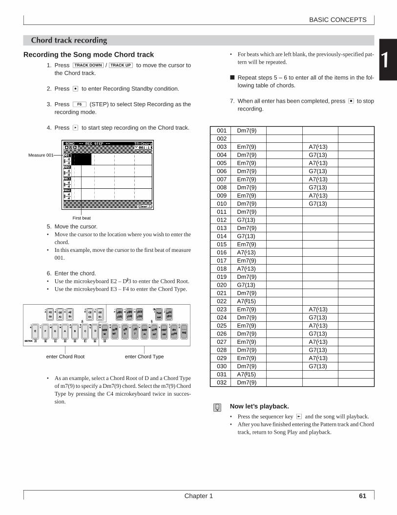
61
BASIC CONCEPTS
Chapter 1
1Chord track recording
Recording the Song mode Chord track1. Press d/u to move the cursor to
the Chord track.
2. Press e to enter Recording Standby condition.
3. Press 6 (STEP) to select Step Recording as therecording mode.
4. Press p to start step recording on the Chord track.
5. Move the cursor.• Move the cursor to the location where you wish to enter the
chord.• In this example, move the cursor to the first beat of measure
001.
6. Enter the chord.• Use the microkeyboard E2 – D
#3 to enter the Chord Root.
• Use the microkeyboard E3 – F4 to enter the Chord Type.
• As an example, select a Chord Root of D and a Chord Typeof m7(9) to specify a Dm7(9) chord. Select the m7(9) ChordType by pressing the C4 microkeyboard twice in succes-sion.
• For beats which are left blank, the previously-specified pat-tern will be repeated.
■ Repeat steps 5 – 6 to enter all of the items in the fol-lowing table of chords.
7. When all enter has been completed, press s to stoprecording.
Now let’s playback.
• Press the sequencer key r and the song will playback.• After you have finished entering the Pattern track and Chord
track, return to Song Play and playback.
001 Dm7(9)002003 Em7(9) A7(b13)004 Dm7(9) G7(13)005 Em7(9) A7(b13)006 Dm7(9) G7(13)007 Em7(9) A7(b13)008 Dm7(9) G7(13)009 Em7(9) A7(b13)010 Dm7(9) G7(13)011 Dm7(9)012 G7(13)013 Dm7(9)014 G7(13)015 Em7(9)016 A7(b13)017 Em7(9)018 A7(b13)019 Dm7(9)020 G7(13)021 Dm7(9)022 A7(#15)023 Em7(9) A7(b13)024 Dm7(9) G7(13)025 Em7(9) A7(b13)026 Dm7(9) G7(13)027 Em7(9) A7(b13)028 Dm7(9) G7(13)029 Em7(9) A7(b13)030 Dm7(9) G7(13)031 A7(#15)032 Dm7(9)
F #
E F G A B C DM
add9
M7
add9
a
m
mM7
m6
c
C # D #7(#5)
7( b5)
7(#9) 7sus4
sus4
SECTION A
G b D b E b 7( b9)
m7(b5)
M7(9)
6
6(9)
7
7(9) m7(9)
m7
dimZWV
/
HGF
UTSRQPO#
N
CBA
?MLK
_ ! S % &
E)
D(
_
YX
aug
7( b13)
7(13) 7(#11)
JI m7(11)
c
G #A b
A #B b
B C D E F G H
enter Chord Root enter Chord Type
Measure 001
First beat
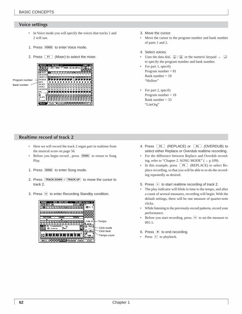
62
BASIC CONCEPTS
Chapter 1
Realtime record of track 2
Voice settings
• Here we will record the track 2 organ part in realtime fromthe musical score on page 56.
• Before you begin record , press s to return to SongPlay.
1. Press s to enter Song mode.
2. Press d/u to move the cursor totrack 2.
3. Press e to enter Recording Standby condition.
4. Press 3 (REPLACE) or 4 (OVERDUB) toselect either Replace or Overdub realtime recording.
• For the difference between Replace and Overdub record-ing, refer to “Chapter 2. SONG MODE” (→ p.109).
• In this example, press 3 (REPLACE) to select Re-place recording, so that you will be able to re-do the record-ing repeatedly as desired.
5. Press p to start realtime recording of track 2.• The play indicator will blink in time to the tempo, and after
a count of several measures, recording will begin. With thedefault settings, there will be one measure of quarter-noteclicks.
• While listening to the previously-record patterns, record yourperformance.
• Before you start recording, press t to set the measure to001:1.
6. Press s to end recording.• Press p to playback.
• In Voice mode you will specify the voices that tracks 1 and2 will use.
1. Press v to enter Voice mode.
2. Press 1 (Mixer) to select the mixer.
3. Move the cursor.• Move the cursor to the program number and bank number
of parts 1 and 2.
4. Select voices.• Uses the data dial, n/y or the numeric keypad → e
to specify the program number and bank number.• For part 1, specify
Program number = 81Bank number = 18“Hollow”
• For part 2, specifyProgram number = 18Bank number = 33“LiteOrg”
Tempo
Click modeClick beat
Tempo count
Program number
Bank number
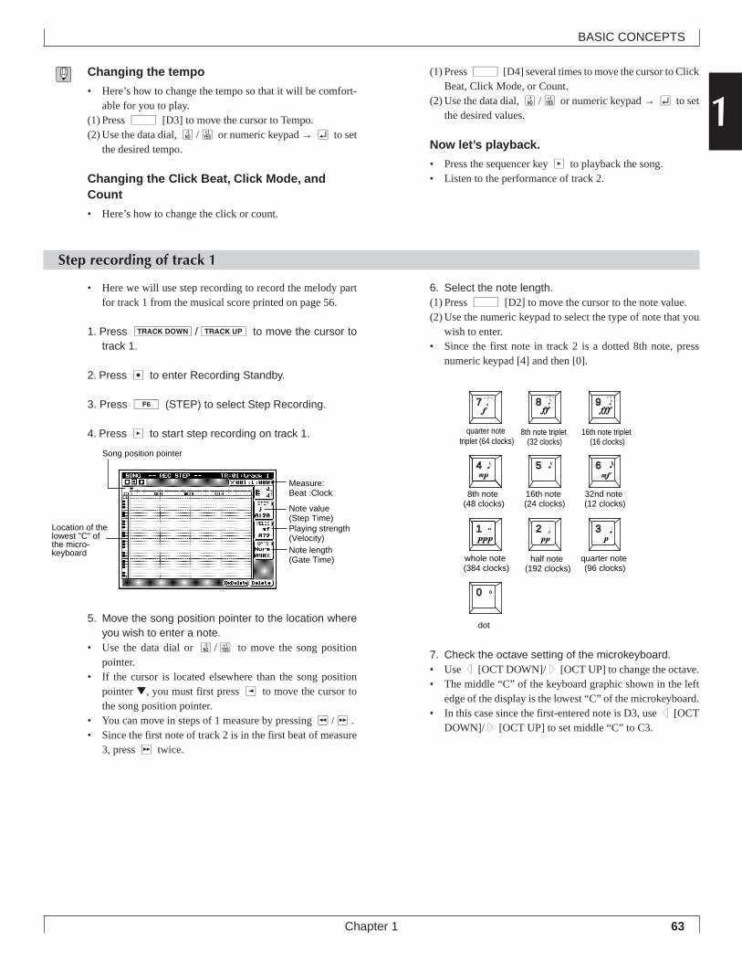
63
BASIC CONCEPTS
Chapter 1
1Changing the tempo
• Here’s how to change the tempo so that it will be comfort-able for you to play.
(1) Press d [D3] to move the cursor to Tempo.(2) Use the data dial, n/y or numeric keypad → e to set
the desired tempo.
Changing the Click Beat, Click Mode, andCount
• Here’s how to change the click or count.
(1) Press d [D4] several times to move the cursor to ClickBeat, Click Mode, or Count.
(2) Use the data dial, n/y or numeric keypad → e to setthe desired values.
Now let’s playback.
• Press the sequencer key p to playback the song.• Listen to the performance of track 2.
Step recording of track 1
• Here we will use step recording to record the melody partfor track 1 from the musical score printed on page 56.
1. Press d/u to move the cursor totrack 1.
2. Press e to enter Recording Standby.
3. Press 6 (STEP) to select Step Recording.
4. Press p to start step recording on track 1.
5. Move the song position pointer to the location whereyou wish to enter a note.
• Use the data dial or n/y to move the song positionpointer.
• If the cursor is located elsewhere than the song positionpointer ▼, you must first press l to move the cursor tothe song position pointer.
• You can move in steps of 1 measure by pressing r/f.• Since the first note of track 2 is in the first beat of measure
3, press f twice.
6. Select the note length.(1) Press d [D2] to move the cursor to the note value.(2) Use the numeric keypad to select the type of note that you
wish to enter.• Since the first note in track 2 is a dotted 8th note, press
numeric keypad [4] and then [0].
7. Check the octave setting of the microkeyboard.• Use d [OCT DOWN]/u [OCT UP] to change the octave.• The middle “C” of the keyboard graphic shown in the left
edge of the display is the lowest “C” of the microkeyboard.• In this case since the first-entered note is D3, use d [OCT
DOWN]/u [OCT UP] to set middle “C” to C3.
7 8 9
4 5 6
1 2 3
0
quarter note triplet (64 clocks)
8th note triplet (32 clocks)
16th note triplet (16 clocks)
8th note (48 clocks)
16th note (24 clocks)
32nd note (12 clocks)
whole note (384 clocks)
half note (192 clocks)
quarter note (96 clocks)
dot
Location of the lowest "C" of the micro-keyboard
Measure:Beat :Clock
Note value (Step Time)Playing strength (Velocity)Note length(Gate Time)
Song position pointer
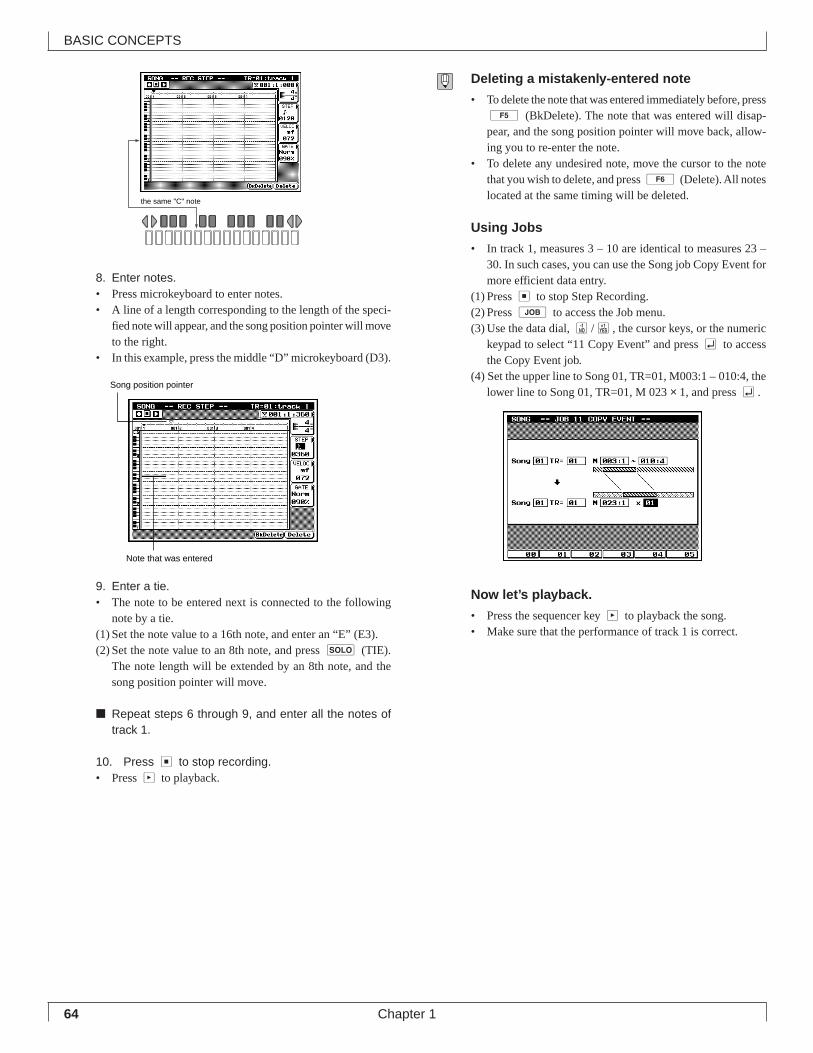
64
BASIC CONCEPTS
Chapter 1
8. Enter notes.• Press microkeyboard to enter notes.• A line of a length corresponding to the length of the speci-
fied note will appear, and the song position pointer will moveto the right.
• In this example, press the middle “D” microkeyboard (D3).
9. Enter a tie.• The note to be entered next is connected to the following
note by a tie.(1) Set the note value to a 16th note, and enter an “E” (E3).(2) Set the note value to an 8th note, and press s (TIE).
The note length will be extended by an 8th note, and thesong position pointer will move.
■ Repeat steps 6 through 9, and enter all the notes oftrack 1.
10. Press s to stop recording.• Press p to playback.
Deleting a mistakenly-entered note
• To delete the note that was entered immediately before, press5 (BkDelete). The note that was entered will disap-pear, and the song position pointer will move back, allow-ing you to re-enter the note.
• To delete any undesired note, move the cursor to the notethat you wish to delete, and press 6 (Delete). All noteslocated at the same timing will be deleted.
Using Jobs
• In track 1, measures 3 – 10 are identical to measures 23 –30. In such cases, you can use the Song job Copy Event formore efficient data entry.
(1) Press s to stop Step Recording.(2) Press j to access the Job menu.(3) Use the data dial, n/y, the cursor keys, or the numeric
keypad to select “11 Copy Event” and press e to accessthe Copy Event job.
(4) Set the upper line to Song 01, TR=01, M003:1 – 010:4, thelower line to Song 01, TR=01, M 023 × 1, and press e.
Now let’s playback.
• Press the sequencer key p to playback the song.• Make sure that the performance of track 1 is correct.
the same "C" note
Note that was entered
Song position pointer
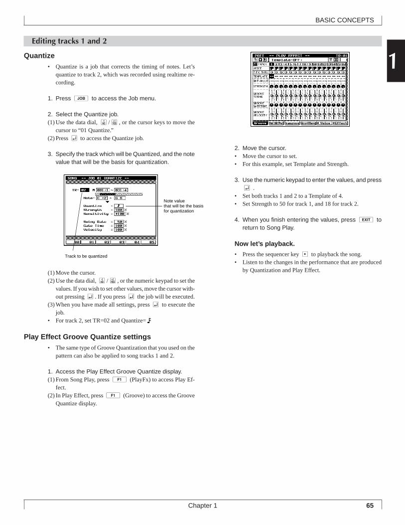
65
BASIC CONCEPTS
Chapter 1
1Editing tracks 1 and 2
Quantize• Quantize is a job that corrects the timing of notes. Let’s
quantize to track 2, which was recorded using realtime re-cording.
1. Press j to access the Job menu.
2. Select the Quantize job.(1) Use the data dial, n/y, or the cursor keys to move the
cursor to “01 Quantize.”(2) Press e to access the Quantize job.
3. Specify the track which will be Quantized, and the notevalue that will be the basis for quantization.
(1) Move the cursor.(2) Use the data dial, n/y, or the numeric keypad to set the
values. If you wish to set other values, move the cursor with-out pressing e. If you press e the job will be executed.
(3) When you have made all settings, press e to execute thejob.
• For track 2, set TR=02 and Quantize=
Play Effect Groove Quantize settings• The same type of Groove Quantization that you used on the
pattern can also be applied to song tracks 1 and 2.
1. Access the Play Effect Groove Quantize display.(1) From Song Play, press 1 (PlayFx) to access Play Ef-
fect.(2) In Play Effect, press 1 (Groove) to access the Groove
Quantize display.
2. Move the cursor.• Move the cursor to set.• For this example, set Template and Strength.
3. Use the numeric keypad to enter the values, and presse .
• Set both tracks 1 and 2 to a Template of 4.• Set Strength to 50 for track 1, and 18 for track 2.
4. When you finish entering the values, press e toreturn to Song Play.
Now let’s playback.
• Press the sequencer key p to playback the song.• Listen to the changes in the performance that are produced
by Quantization and Play Effect.
Track to be quantized
Note value that will be the basis for quantization
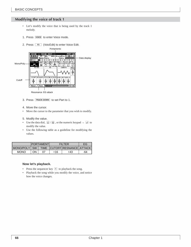
66
BASIC CONCEPTS
Chapter 1
Modifying the voice of track 1
• Let’s modify the voice that is being used by the track 1melody.
1. Press v to enter Voice mode.
2. Press 3 (VoicEdit) to enter Voice Edit.
3. Press d to set Part to 1.
4. Move the cursor.• Move the cursor to the parameter that you wish to modify.
5. Modify the value.• Use the data dial, n/y, or the numeric keypad → e to
modify the value.• Use the following table as a guideline for modifying the
values.
Now let’s playback.
• Press the sequencer key p to playback the song.• Playback the song while you modify the voice, and notice
how the voice changes.
Portamento
Data display
EG attackResonance
Cutoff
Mono/Poly
PORTAMENT FILTER EGMONO/POLY SW TIME CUTOFF RESNANCE ATTACK
MONO ON 07 +16 +43 -64
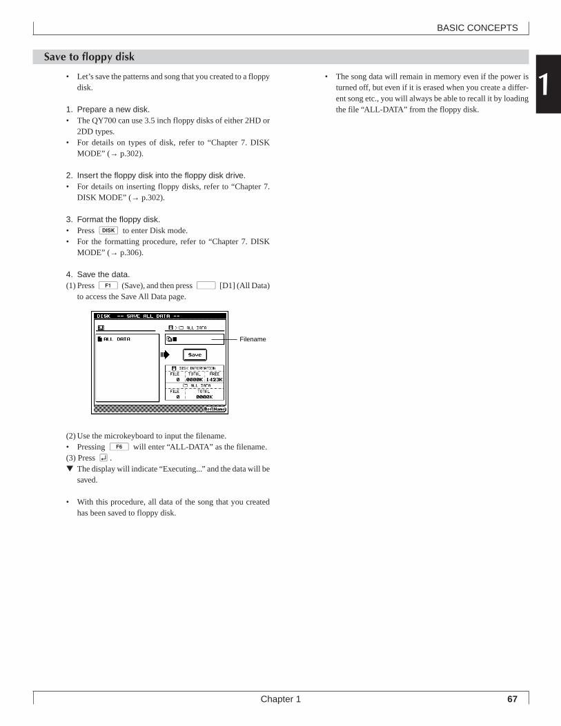
67
BASIC CONCEPTS
Chapter 1
1Save to floppy disk
• Let’s save the patterns and song that you created to a floppydisk.
1. Prepare a new disk.• The QY700 can use 3.5 inch floppy disks of either 2HD or
2DD types.• For details on types of disk, refer to “Chapter 7. DISK
MODE” (→ p.302).
2. Insert the floppy disk into the floppy disk drive.• For details on inserting floppy disks, refer to “Chapter 7.
DISK MODE” (→ p.302).
3. Format the floppy disk.• Press d to enter Disk mode.• For the formatting procedure, refer to “Chapter 7. DISK
MODE” (→ p.306).
4. Save the data.(1) Press 1 (Save), and then press d [D1] (All Data)
to access the Save All Data page.
(2) Use the microkeyboard to input the filename.• Pressing 6 will enter “ALL-DATA” as the filename.(3) Press e.▼ The display will indicate “Executing...” and the data will be
saved.
• With this procedure, all data of the song that you createdhas been saved to floppy disk.
Filename
• The song data will remain in memory even if the power isturned off, but even if it is erased when you create a differ-ent song etc., you will always be able to recall it by loadingthe file “ALL-DATA” from the floppy disk.
68
BASIC CONCEPTS
Chapter 1
Memo
Chapter 2. SONG MODE
You use SONG mode to play, edit, and record your songs. This chap-
ter explains all SONG-mode operations.
2
SONG MODE Overview ................................. 701. SONG PLAY............................................... 722. Play Effects ................................................ 803. Track View ................................................ 1004. Output Channels ...................................... 1035. Song Recording ....................................... 1066. Song Editing ............................................. 1297. Song Jobs ................................................ 138
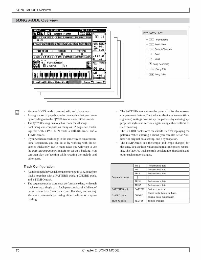
70 Chapter 2. SONG MODE
• The PATTERN track stores the pattern list for the auto-ac-companiment feature. The track can also include meter (timesignature) settings. You set up the patterns by entering ap-propriate styles and sections, again using either realtime orstep recording.
• The CHORD track stores the chords used for replaying thepatterns. When entering a chord, you can also set an “on-bass” or original bass setting, and a syncopation.
• The TEMPO track sets the tempo (and tempo changes) forthe song. You set these values using realtime or step record-ing. The TEMPO track controls accelerando, ritardando, andother such tempo changes.
SONG MODE Overview
• You use SONG mode to record, edit, and play songs.• A song is a set of playable performance data that you create
by recording onto the QY700 tracks under SONG mode.• The QY700’s song memory has room for 20 songs.• Each song can comprise as many as 32 sequence tracks,
together with a PATTERN track, a CHORD track, and aTEMPO track.
• If you wish to record songs in the same way as on a conven-tional sequencer, you can do so by working with the se-quence tracks only. But in many cases you will want to usethe auto-accompaniment feature to set up a backing. Youcan then play the backing while creating the melody andother parts.
Track Configuration
• As mentioned above, each song comprises up to 32 sequencetracks, together with a PATTERN track, a CHORD track,and a TEMPO track.
• The sequence tracks store your performance data, with eachtrack storing a single part. Each part consists of a full set ofperformance data (note data, controller data, and so on).You can create each part using either realtime or step re-cording.
SONG MODE Overview
Sequence tracks
TR 1 Performance data
TR 2 Performance data
TR 3 Performance data
TR 31 Performance data
TR 32 Performance data
PATTERN track PATTERN Patterns, meters
CHORD track CHORDChord roots, types, on-bass,
original bass, syncopation
TEMPO track TEMPO Tempo changes
1ÊPlay Effects
2Track View
3Output Channels
5Save
6Load
eSong Recording
eSong Edit
jSong Jobs
sSONG PLAY
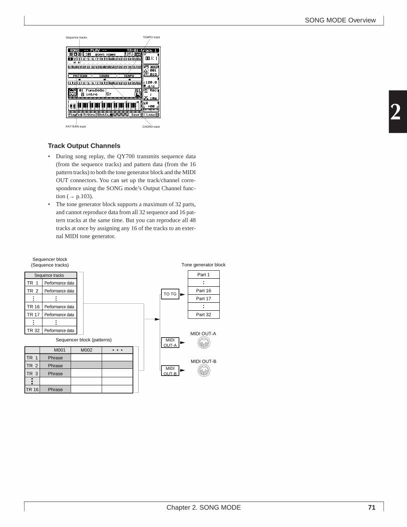
71Chapter 2. SONG MODE
2Track Output Channels
• During song replay, the QY700 transmits sequence data(from the sequence tracks) and pattern data (from the 16pattern tracks) to both the tone generator block and the MIDIOUT connectors. You can set up the track/channel corre-spondence using the SONG mode’s Output Channel func-tion (→ p.103).
• The tone generator block supports a maximum of 32 parts,and cannot reproduce data from all 32 sequence and 16 pat-tern tracks at the same time. But you can reproduce all 48tracks at once by assigning any 16 of the tracks to an exter-nal MIDI tone generator.
SONG MODE Overview
Sequence tracks TEMPO track
PATTERN track CHORD track
TR 1 Phrase
TR 2 Phrase
TR 3 Phrase
TR 16 Phrase
M001 M002 • • •
Part 1
Part 16
Part 17
Part 32
MIDI OUT-A
MIDI OUT-B
Sequencer block (patterns)
TR 1 Performance data
TR 2 Performance data
TR 16 Performance data
TR 17 Performance data
TR 32 Performance data
Sequence tracks
Sequencer block(Sequence tracks)
TO TG
MIDIOUT-A
MIDIOUT-B
Tone generator block
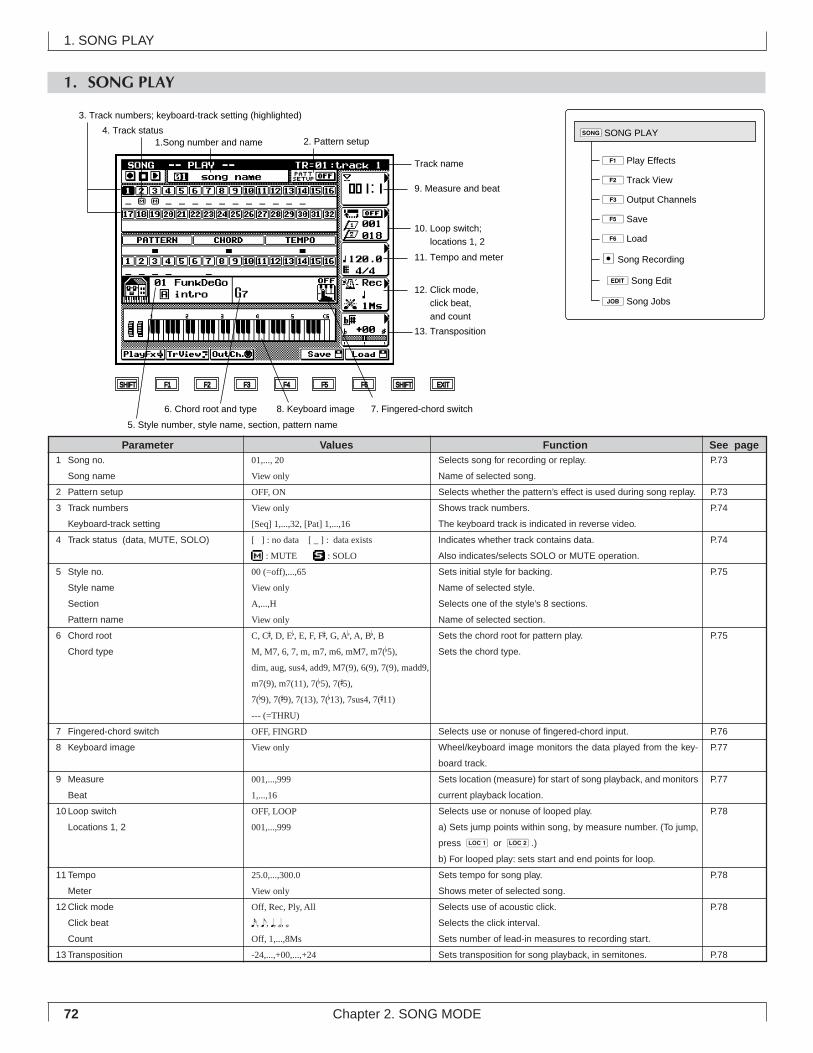
72 Chapter 2. SONG MODE
1. SONG PLAY
12. Click mode, click beat, and count
6. Chord root and type
SHIFT F1 F2 F3 F4 F5 F6 SHIFT EXIT
Track name
10. Loop switch; locations 1, 2
9. Measure and beat
11. Tempo and meter
8. Keyboard image
13. Transposition
5. Style number, style name, section, pattern name
7. Fingered-chord switch
4. Track status
3. Track numbers; keyboard-track setting (highlighted)
1.Song number and name 2. Pattern setup
1Play Effects
2Track View
3Output Channels
5Save
6Load
eSong Recording
eSong Edit
jSong Jobs
sSONG PLAY
Selects song for recording or replay.
Name of selected song.
Selects whether the pattern’s effect is used during song replay.
Shows track numbers.
The keyboard track is indicated in reverse video.
Indicates whether track contains data.
Also indicates/selects SOLO or MUTE operation.
Sets initial style for backing.
Name of selected style.
Selects one of the style’s 8 sections.
Name of selected section.
Sets the chord root for pattern play.
Sets the chord type.
Selects use or nonuse of fingered-chord input.
Wheel/keyboard image monitors the data played from the key-
board track.
Sets location (measure) for start of song playback, and monitors
current playback location.
Selects use or nonuse of looped play.
a) Sets jump points within song, by measure number. (To jump,
press 1 or 2.)
b) For looped play: sets start and end points for loop.
Sets tempo for song play.
Shows meter of selected song.
Selects use of acoustic click.
Selects the click interval.
Sets number of lead-in measures to recording start.
Sets transposition for song playback, in semitones.
01,..., 20
View only
OFF, ON
View only
[Seq] 1,...,32, [Pat] 1,...,16
[ ] : no data [ _ ] : data exists
: MUTE : SOLO
00 (=off),...,65
View only
A,...,H
View only
C, C#, D, Eb, E, F, F#, G, Ab, A, Bb, BM, M7, 6, 7, m, m7, m6, mM7, m7(b5),
dim, aug, sus4, add9, M7(9), 6(9), 7(9), madd9,
m7(9), m7(11), 7(b5), 7(#5),
7(b9), 7(#9), 7(13), 7(b13), 7sus4, 7(#11)
--- (=THRU)
OFF, FINGRD
View only
001,...,999
1,...,16
OFF, LOOP
001,...,999
25.0,...,300.0
View only
Off, Rec, Ply, All
x, e, q, h, úOff, 1,...,8Ms
-24,...,+00,...,+24
1 Song no.
Song name
2 Pattern setup
3 Track numbers
Keyboard-track setting
4 Track status (data, MUTE, SOLO)
5 Style no.
Style name
Section
Pattern name
6 Chord root
Chord type
7 Fingered-chord switch
8 Keyboard image
9 Measure
Beat
10 Loop switch
Locations 1, 2
11 Tempo
Meter
12 Click mode
Click beat
Count
13 Transposition
Parameter Values Function See pageP.73
P.73
P.74
P.74
P.75
P.75
P.76
P.77
P.77
P.78
P.78
P.78
P.78
1. SONG PLAY
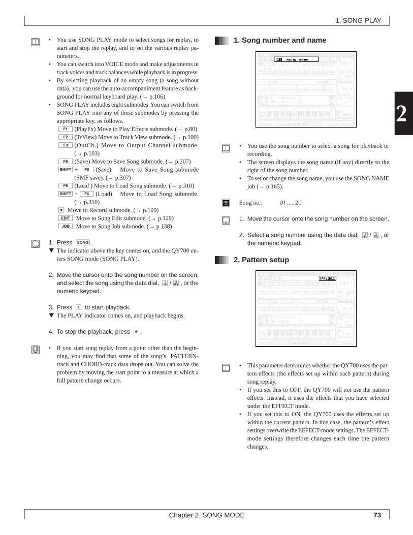
73Chapter 2. SONG MODE
2
• You use SONG PLAY mode to select songs for replay, tostart and stop the replay, and to set the various replay pa-rameters.
• You can switch into VOICE mode and make adjustments intrack voices and track balances while playback is in progress.
• By selecting playback of an empty song (a song withoutdata), you can use the auto-accompaniment feature as back-ground for normal keyboard play. (→ p.106)
• SONG PLAY includes eight submodes. You can switch fromSONG PLAY into any of these submodes by pressing theappropriate key, as follows.1(PlayFx) Move to Play Effects submode. (→ p.80)2(TrView) Move to Track View submode. (→ p.100)3(OutCh.) Move to Output Channel submode.
(→ p.103)5(Save) Move to Save Song submode. (→ p.307)s+5(Save) Move to Save Song submode
(SMF save). (→ p.307)6(Load ) Move to Load Song submode. (→ p.310)s+6(Load) Move to Load Song submode.
(→ p.310)e Move to Record submode. (→ p.109)e Move to Song Edit submode. (→ p.129)j Move to Song Job submode. (→ p.138)
1. Press s.▼ The indicator above the key comes on, and the QY700 en-
ters SONG mode (SONG PLAY).
2. Move the cursor onto the song number on the screen,and select the song using the data dial, n/y, or thenumeric keypad.
3. Press p to start playback.▼ The PLAY indicator comes on, and playback begins.
4. To stop the playback, press s.
• If you start song replay from a point other than the begin-ning, you may find that some of the song’s PATTERN-track and CHORD-track data drops out. You can solve theproblem by moving the start point to a measure at which afull pattern change occurs.
1. Song number and name
• You use the song number to select a song for playback orrecording.
• The screen displays the song name (if any) directly to theright of the song number.
• To set or change the song name, you use the SONG NAMEjob (→ p.165).
01011101 Song no.: 01,...,20
1. Move the cursor onto the song number on the screen.
2. Select a song number using the data dial, n/y, orthe numeric keypad.
2. Pattern setup
• This parameter determines whether the QY700 uses the pat-tern effects (the effects set up within each pattern) duringsong replay.
• If you set this to OFF, the QY700 will not use the patterneffects. Instead, it uses the effects that you have selectedunder the EFFECT mode.
• If you set this to ON, the QY700 uses the effects set upwithin the current pattern. In this case, the pattern’s effectsettings overwrite the EFFECT-mode settings. The EFFECT-mode settings therefore changes each time the patternchanges.
1. SONG PLAY
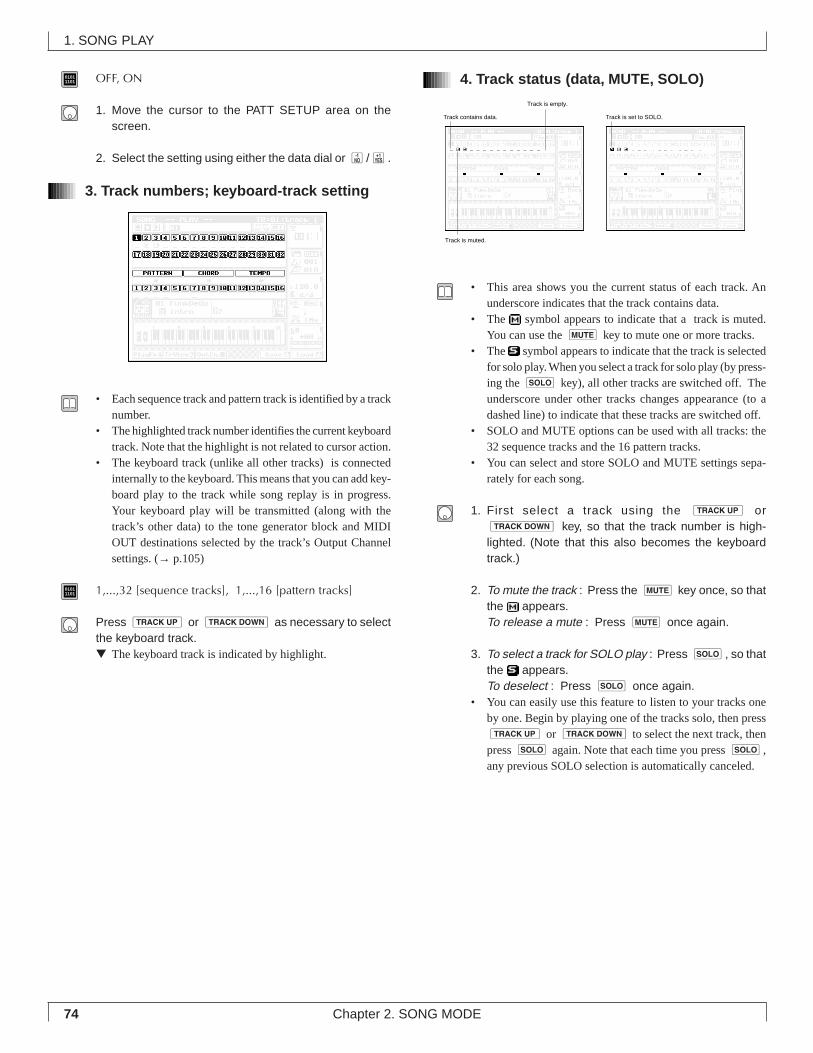
74 Chapter 2. SONG MODE
01011101 OFF, ON
1. Move the cursor to the PATT SETUP area on thescreen.
2. Select the setting using either the data dial or n/y.
3. Track numbers; keyboard-track setting
• Each sequence track and pattern track is identified by a tracknumber.
• The highlighted track number identifies the current keyboardtrack. Note that the highlight is not related to cursor action.
• The keyboard track (unlike all other tracks) is connectedinternally to the keyboard. This means that you can add key-board play to the track while song replay is in progress.Your keyboard play will be transmitted (along with thetrack’s other data) to the tone generator block and MIDIOUT destinations selected by the track’s Output Channelsettings. (→ p.105)
01011101 1,...,32 [sequence tracks], 1,...,16 [pattern tracks]
Press u or d as necessary to selectthe keyboard track.▼ The keyboard track is indicated by highlight.
4. Track status (data, MUTE, SOLO)
• This area shows you the current status of each track. Anunderscore indicates that the track contains data.
• The symbol appears to indicate that a track is muted.You can use the m key to mute one or more tracks.
• The symbol appears to indicate that the track is selectedfor solo play. When you select a track for solo play (by press-ing the s key), all other tracks are switched off. Theunderscore under other tracks changes appearance (to adashed line) to indicate that these tracks are switched off.
• SOLO and MUTE options can be used with all tracks: the32 sequence tracks and the 16 pattern tracks.
• You can select and store SOLO and MUTE settings sepa-rately for each song.
1. First select a track using the u ord key, so that the track number is high-lighted. (Note that this also becomes the keyboardtrack.)
2. To mute the track : Press the m key once, so thatthe appears.To release a mute : Press m once again.
3. To select a track for SOLO play : Press s, so thatthe appears.To deselect : Press s once again.
• You can easily use this feature to listen to your tracks oneby one. Begin by playing one of the tracks solo, then pressu or d to select the next track, thenpress s again. Note that each time you press s,any previous SOLO selection is automatically canceled.
Track contains data.
Track is empty.
Track is muted.
Track is set to SOLO.
1. SONG PLAY
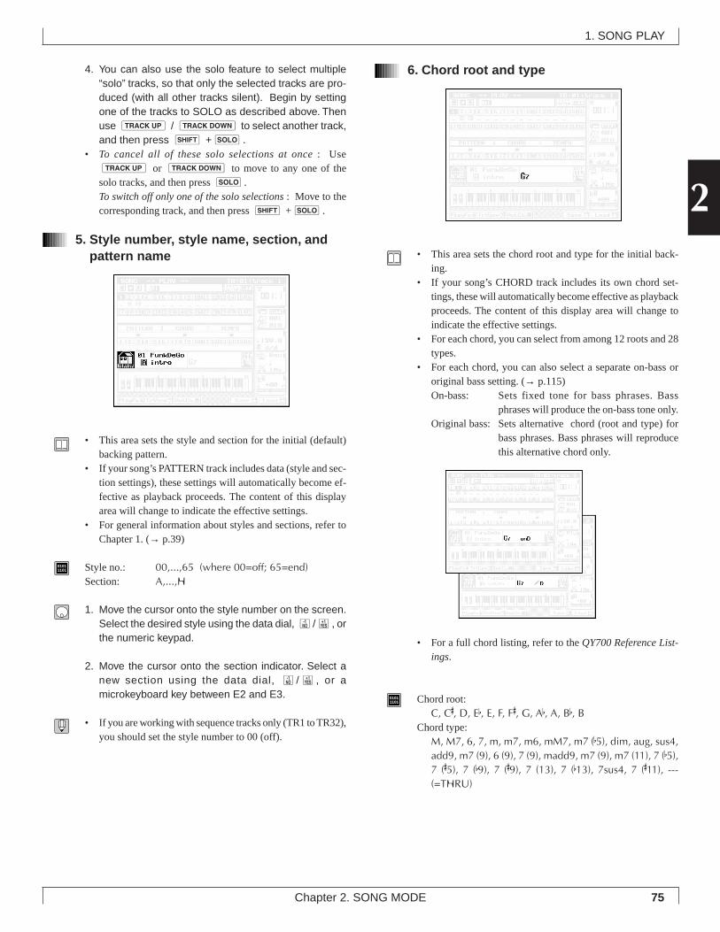
75Chapter 2. SONG MODE
2
4. You can also use the solo feature to select multiple“solo” tracks, so that only the selected tracks are pro-duced (with all other tracks silent). Begin by settingone of the tracks to SOLO as described above. Thenuse u / d to select another track,and then press s +s.
• To cancel all of these solo selections at once : Useu or d to move to any one of thesolo tracks, and then press s.To switch off only one of the solo selections : Move to thecorresponding track, and then press s +s.
5. Style number, style name, section, andpattern name
• This area sets the style and section for the initial (default)backing pattern.
• If your song’s PATTERN track includes data (style and sec-tion settings), these settings will automatically become ef-fective as playback proceeds. The content of this displayarea will change to indicate the effective settings.
• For general information about styles and sections, refer toChapter 1. (→ p.39)
01011101 Style no.: 00,...,65 (where 00=off; 65=end)
Section: A,...,H
1. Move the cursor onto the style number on the screen.Select the desired style using the data dial, n/y, orthe numeric keypad.
2. Move the cursor onto the section indicator. Select anew section using the data dial, n/y, or amicrokeyboard key between E2 and E3.
• If you are working with sequence tracks only (TR1 to TR32),you should set the style number to 00 (off).
6. Chord root and type
• This area sets the chord root and type for the initial back-ing.
• If your song’s CHORD track includes its own chord set-tings, these will automatically become effective as playbackproceeds. The content of this display area will change toindicate the effective settings.
• For each chord, you can select from among 12 roots and 28types.
• For each chord, you can also select a separate on-bass ororiginal bass setting. (→ p.115)On-bass: Sets fixed tone for bass phrases. Bass
phrases will produce the on-bass tone only.Original bass: Sets alternative chord (root and type) for
bass phrases. Bass phrases will reproducethis alternative chord only.
• For a full chord listing, refer to the QY700 Reference List-ings.
01011101 Chord root:
C, C#, D, Eb, E, F, F#, G, Ab, A, Bb, BChord type:
M, M7, 6, 7, m, m7, m6, mM7, m7 (b5), dim, aug, sus4,add9, m7 (9), 6 (9), 7 (9), madd9, m7 (9), m7 (11), 7 (b5),7 (#5), 7 (b9), 7 (#9), 7 (13), 7 (b13), 7sus4, 7 (#11), ---(=THRU)
1. SONG PLAY
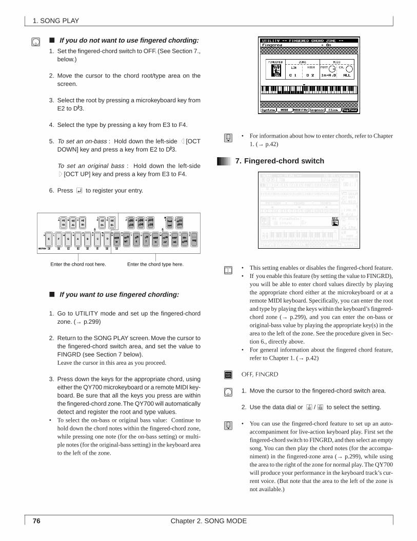
76 Chapter 2. SONG MODE
■ If you do not want to use fingered chording:
1. Set the fingered-chord switch to OFF. (See Section 7.,below.)
2. Move the cursor to the chord root/type area on thescreen.
3. Select the root by pressing a microkeyboard key fromE2 to D#3.
4. Select the type by pressing a key from E3 to F4.
5. To set an on-bass : Hold down the left-side d [OCTDOWN] key and press a key from E2 to D#3.
To set an original bass : Hold down the left-sideu[OCT UP] key and press a key from E3 to F4.
6. Press e to register your entry.
■ If you want to use fingered chording:
1. Go to UTILITY mode and set up the fingered-chordzone. (→ p.299)
2. Return to the SONG PLAY screen. Move the cursor tothe fingered-chord switch area, and set the value toFINGRD (see Section 7 below).Leave the cursor in this area as you proceed.
3. Press down the keys for the appropriate chord, usingeither the QY700 microkeyboard or a remote MIDI key-board. Be sure that all the keys you press are withinthe fingered-chord zone. The QY700 will automaticallydetect and register the root and type values.
• To select the on-bass or original bass value: Continue tohold down the chord notes within the fingered-chord zone,while pressing one note (for the on-bass setting) or multi-ple notes (for the original-bass setting) in the keyboard areato the left of the zone.
• For information about how to enter chords, refer to Chapter1. (→ p.42)
7. Fingered-chord switch
• This setting enables or disables the fingered-chord feature.• If you enable this feature (by setting the value to FINGRD),
you will be able to enter chord values directly by playingthe appropriate chord either at the microkeyboard or at aremote MIDI keyboard. Specifically, you can enter the rootand type by playing the keys within the keyboard’s fingered-chord zone (→ p.299), and you can enter the on-bass ororiginal-bass value by playing the appropriate key(s) in thearea to the left of the zone. See the procedure given in Sec-tion 6., directly above.
• For general information about the fingered chord feature,refer to Chapter 1. (→ p.42)
01011101 OFF, FINGRD
1. Move the cursor to the fingered-chord switch area.
2. Use the data dial or n/y to select the setting.
• You can use the fingered-chord feature to set up an auto-accompaniment for live-action keyboard play. First set thefingered-chord switch to FINGRD, and then select an emptysong. You can then play the chord notes (for the accompa-niment) in the fingered-zone area (→ p.299), while usingthe area to the right of the zone for normal play. The QY700will produce your performance in the keyboard track’s cur-rent voice. (But note that the area to the left of the zone isnot available.)
1. SONG PLAY
F #
E F G A B C DM
add9
M7
add9
a
m
mM7
m6
c
C # D #7(#5)
7( b5)
7(#9) 7sus4
sus4
SECTION A
G b D b E b 7( b9)
m7(b5)
M7(9)
6
6(9)
7
7(9) m7(9)
m7
dimZWV
/
HGF
UTSRQPO#
N
CBA
?MLK
_ ! S % &
E)
D(
_
YX
aug
7( b13)
7(13) 7(#11)
JI m7(11)
c
G #A b
A #B b
B C D E F G H
Enter the chord root here. Enter the chord type here.
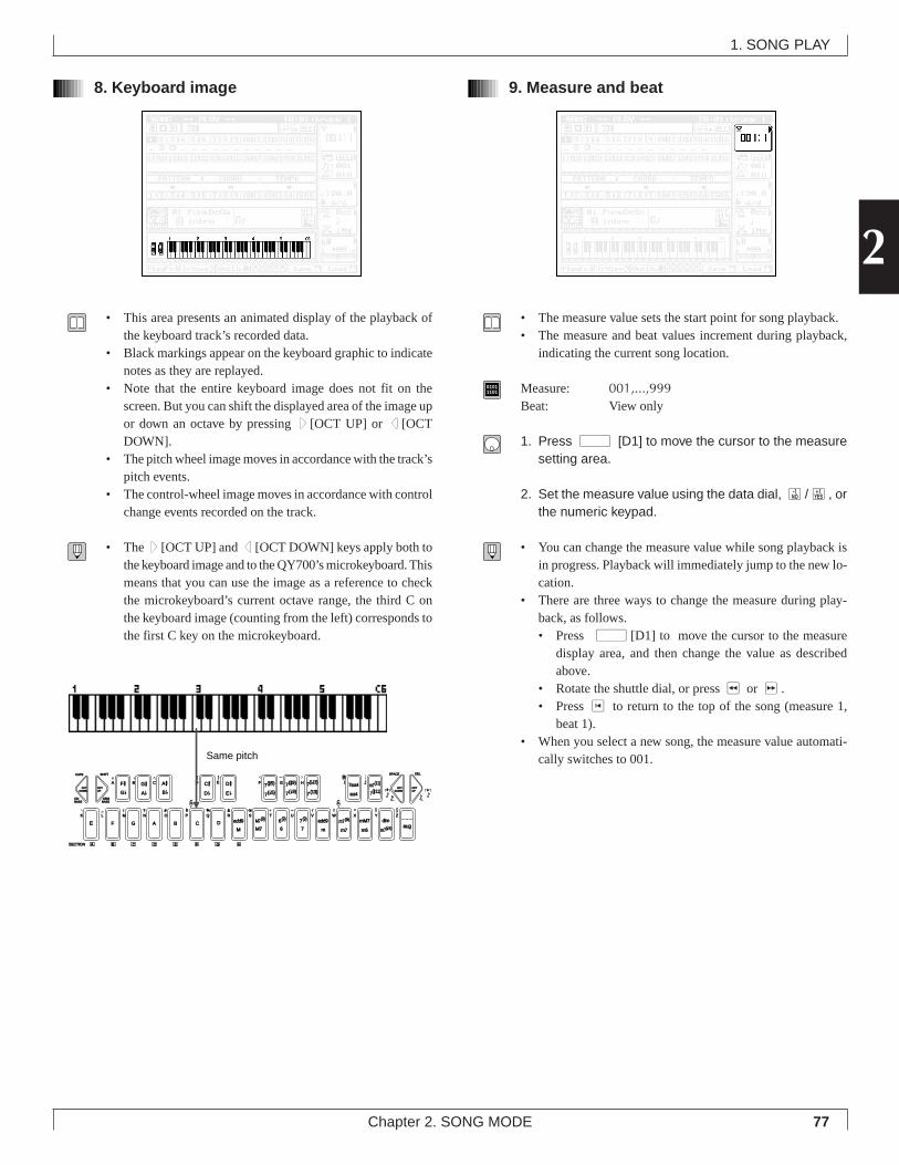
77Chapter 2. SONG MODE
2
8. Keyboard image
• This area presents an animated display of the playback ofthe keyboard track’s recorded data.
• Black markings appear on the keyboard graphic to indicatenotes as they are replayed.
• Note that the entire keyboard image does not fit on thescreen. But you can shift the displayed area of the image upor down an octave by pressing u [OCT UP] or d [OCTDOWN].
• The pitch wheel image moves in accordance with the track’spitch events.
• The control-wheel image moves in accordance with controlchange events recorded on the track.
• The u [OCT UP] and d [OCT DOWN] keys apply both tothe keyboard image and to the QY700’s microkeyboard. Thismeans that you can use the image as a reference to checkthe microkeyboard’s current octave range, the third C onthe keyboard image (counting from the left) corresponds tothe first C key on the microkeyboard.
9. Measure and beat
• The measure value sets the start point for song playback.• The measure and beat values increment during playback,
indicating the current song location.
01011101 Measure: 001,...,999
Beat: View only
1. Press d [D1] to move the cursor to the measuresetting area.
2. Set the measure value using the data dial, n/y, orthe numeric keypad.
• You can change the measure value while song playback isin progress. Playback will immediately jump to the new lo-cation.
• There are three ways to change the measure during play-back, as follows.• Press d[D1] to move the cursor to the measure
display area, and then change the value as describedabove.
• Rotate the shuttle dial, or press r or f.• Press t to return to the top of the song (measure 1,
beat 1).• When you select a new song, the measure value automati-
cally switches to 001.
1. SONG PLAY
OCTDOWN
OCTUP
OCTDOWN
OCTUP
ONBASS
F #
E F G A B C DM
add9
M7
add9
a
m
mM7
m6
c
C # D #7(#5)
7( b5)
7(#9) 7sus4
sus4
SECTION A
G b D b E b 7( b9)
m7(b5)
M7(9)
6
6(9)
7
7(9) m7(9)
m7
dimZWV
/
HGF
UTSRQPO#
N
CBA
?MLK
_ ! S % &
E)
D(
_
YX
aug
7( b13)
7(13) 7(#11)
JI m7(11)
ORGBASS
CAPS SHIFT SPACE
3
DEL
c
G #A b
A #B b 3
B C D E F G H
Same pitch
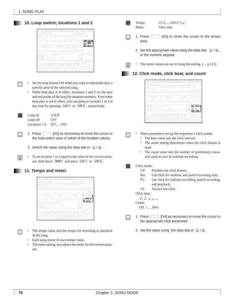
78 Chapter 2. SONG MODE
10. Loop switch; locations 1 and 2
• Set the loop feature ON when you want to repeatedly play aspecific area of the selected song.
• When loop play is in effect, locations 1 and 2 set the startand end points of the loop (by measure number). Even whenloop play is not in effect, you can jump to location 1 or 2 atany time by pressing 1 or 2, respectively.
01011101 Loop on LOOP
Loop off OFFLocations 1/2 001,...,999
1. Press d [D2] as necessary to move the cursor tothe loop-switch area or either of the location values.
2. Switch the value using the data dial or n/y .
• To set location 1 or 2 equal to the value of the current meas-ure, hold down s and press 1 or 2.
11. Tempo and meter
• The tempo value sets the tempo for recording or playbackof the song.
• Each song stores its own tempo value.• The meter setting area shows the meter for the current meas-
ure.
01011101 Tempo 25.0,...,300.0 (=q )
Meter View only
1. Press d [D3] to move the cursor to the tempoarea.
2. Set the appropriate value using the data dial, n/y,or the numeric keypad.
• The meter values are set in Song Recording. (→ p.111)
12. Click mode, click beat, and count
• These parameters set up the sequencer’s click sound.• The beat value sets the click interval.• The mode setting determines when the click feature is
used.• The count value sets the number of preliminary meas-
ures used at start of realtime recording.
01011101 Click mode:
Off Disables the click feature.Rec Use click for realtime and punch recording only.Ply Use click for realtime recording, punch recording,
and playback.All Always use click.
Click beat: x, e, q, h, wCount: Off, 1,...,8Ms
1. Press d [D4] as necessary to move the cursor tothe appropriate click parameter.
2. Set the value using the data dial or n/y.
1. SONG PLAY
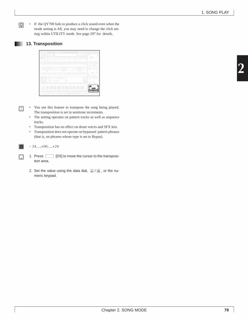
79Chapter 2. SONG MODE
2
• If the QY700 fails to produce a click sound even when themode setting is All, you may need to change the click set-ting within UTILITY mode. See page 297 for details.
13. Transposition
• You use this feature to transpose the song being played.The transposition is set in semitone increments.
• The setting operates on pattern tracks as well as sequencetracks.
• Transposition has no effect on drum voices and SFX kits.• Transposition does not operate on bypassed pattern phrases
(that is, on phrases whose type is set to Bypas).
01011101 – 24,...,+00,...,+24
1. Press d [D5] to move the cursor to the transposi-tion area.
2. Set the value using the data dial, n/y, or the nu-meric keypad.
1. SONG PLAY
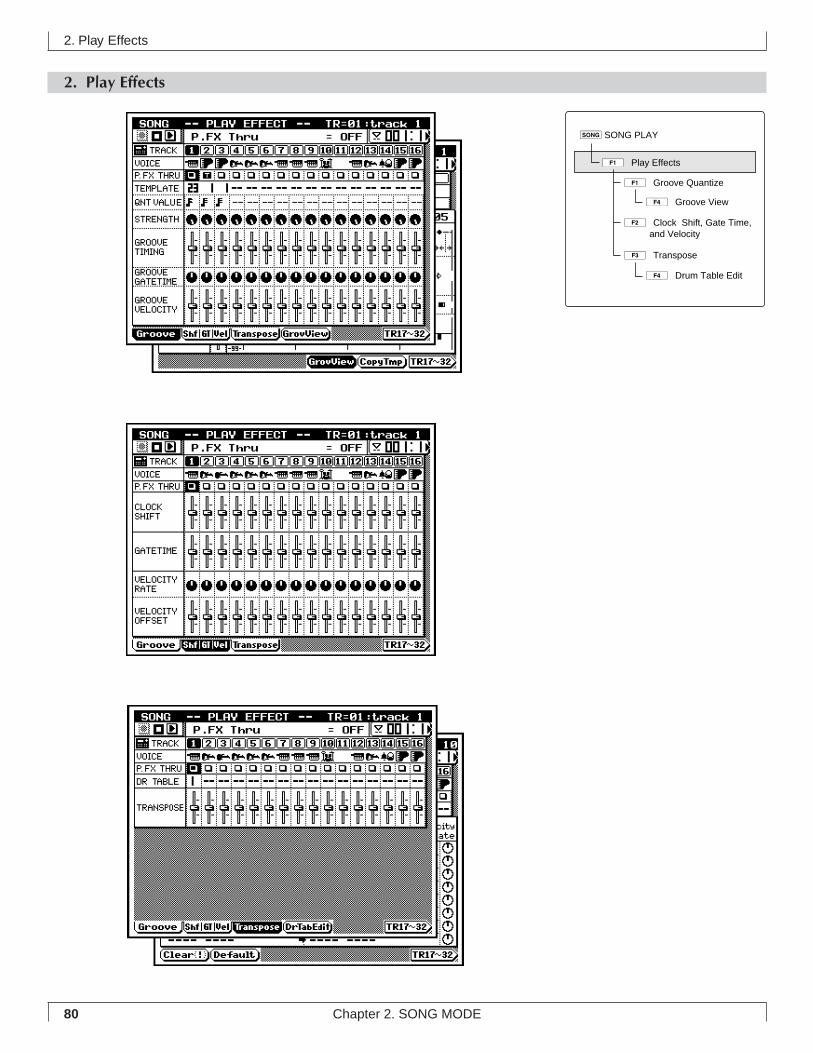
80 Chapter 2. SONG MODE
2. Play Effects
2. Play Effects
1ÊGroove Quantize
4ÊGroove View
3ÊTranspose
2ÊClock Shift, Gate Time, and Velocity
4ÊDrum Table Edit
sSONG PLAY
1ÊPlay Effects
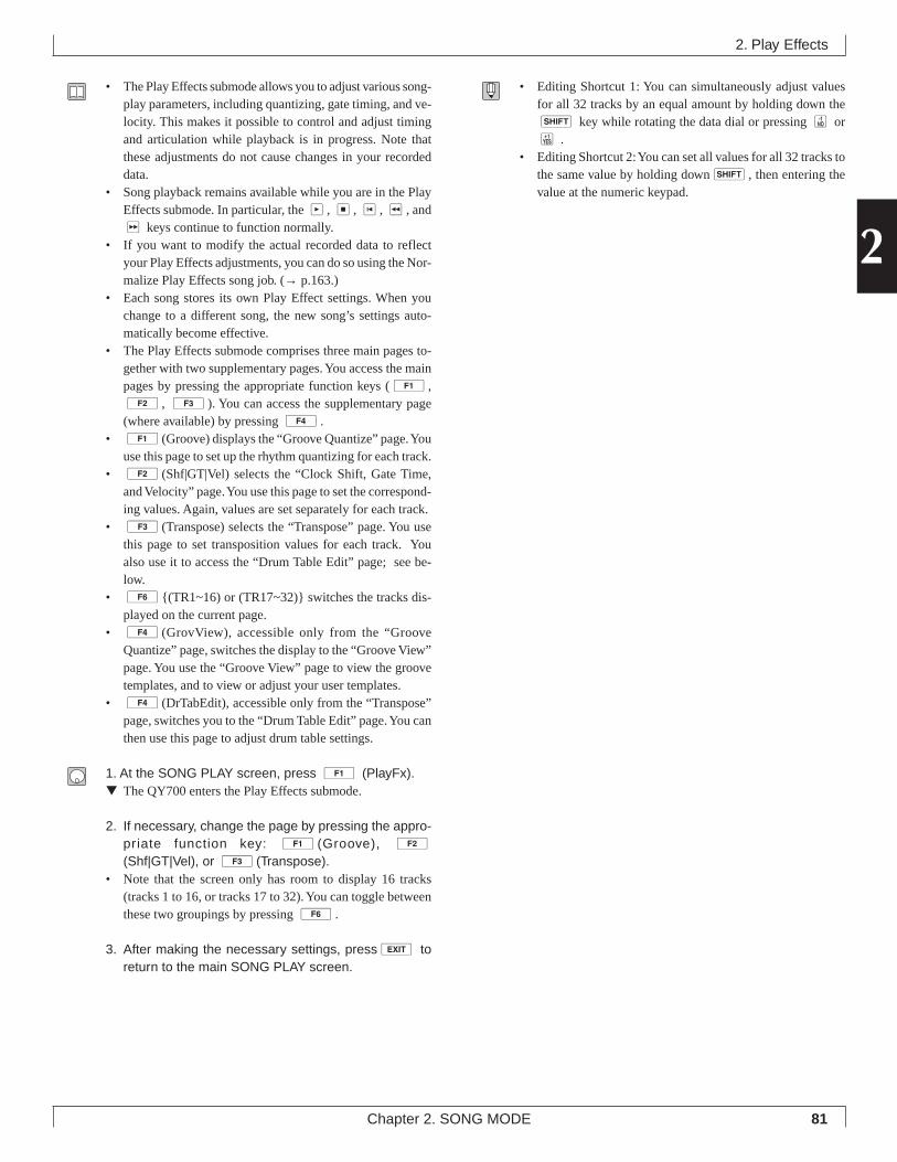
81Chapter 2. SONG MODE
2
• The Play Effects submode allows you to adjust various song-play parameters, including quantizing, gate timing, and ve-locity. This makes it possible to control and adjust timingand articulation while playback is in progress. Note thatthese adjustments do not cause changes in your recordeddata.
• Song playback remains available while you are in the PlayEffects submode. In particular, the p, s, t, r, andf keys continue to function normally.
• If you want to modify the actual recorded data to reflectyour Play Effects adjustments, you can do so using the Nor-malize Play Effects song job. (→ p.163.)
• Each song stores its own Play Effect settings. When youchange to a different song, the new song’s settings auto-matically become effective.
• The Play Effects submode comprises three main pages to-gether with two supplementary pages. You access the mainpages by pressing the appropriate function keys (1,2, 3). You can access the supplementary page(where available) by pressing 4.
• 1(Groove) displays the “Groove Quantize” page. Youuse this page to set up the rhythm quantizing for each track.
• 2(Shf|GT|Vel) selects the “Clock Shift, Gate Time,and Velocity” page. You use this page to set the correspond-ing values. Again, values are set separately for each track.
• 3(Transpose) selects the “Transpose” page. You usethis page to set transposition values for each track. Youalso use it to access the “Drum Table Edit” page; see be-low.
• 6{(TR1~16) or (TR17~32)} switches the tracks dis-played on the current page.
• 4(GrovView), accessible only from the “GrooveQuantize” page, switches the display to the “Groove View”page. You use the “Groove View” page to view the groovetemplates, and to view or adjust your user templates.
• 4(DrTabEdit), accessible only from the “Transpose”page, switches you to the “Drum Table Edit” page. You canthen use this page to adjust drum table settings.
1. At the SONG PLAY screen, press 1 (PlayFx).▼ The QY700 enters the Play Effects submode.
2. If necessary, change the page by pressing the appro-priate function key: 1 (Groove), 2
(Shf|GT|Vel), or 3 (Transpose).• Note that the screen only has room to display 16 tracks
(tracks 1 to 16, or tracks 17 to 32). You can toggle betweenthese two groupings by pressing 6.
3. After making the necessary settings, presse toreturn to the main SONG PLAY screen.
• Editing Shortcut 1: You can simultaneously adjust valuesfor all 32 tracks by an equal amount by holding down thes key while rotating the data dial or pressing n ory .
• Editing Shortcut 2: You can set all values for all 32 tracks tothe same value by holding downs, then entering thevalue at the numeric keypad.
2. Play Effects
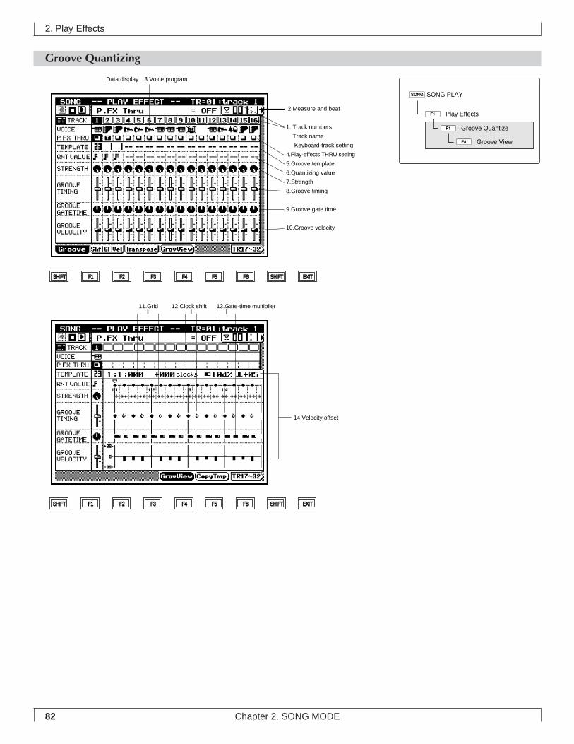
82 Chapter 2. SONG MODE
Groove Quantizing
2. Play Effects
3.Voice program
2.Measure and beat
1. Track numbers
Track name
Keyboard-track setting
4.Play-effects THRU setting
5.Groove template
6.Quantizing value
7.Strength
8.Groove timing
9.Groove gate time
10.Groove velocity
SHIFT F1 F2 F3 F4 F5 F6 SHIFT EXIT
SHIFT F1 F2 F3 F4 F5 F6 SHIFT EXIT
Data display
11.Grid 12.Clock shift 13.Gate-time multiplier
14.Velocity offset
sSONG PLAY
1ÊPlay Effects
1ÊGroove Quantize
4ÊGroove View
83Chapter 2. SONG MODE
2
• You use the groove quantize (rhythm quantization) featureto impart a swing, or “groove,” to the song data as it is playedback. The feature operates by making specified adjustmentsin note-event timing, velocities, and gate times. Effectiveuse of this feature makes it possible to convert mechanical-sounding song data into driving, meaningful music.
• The QY700 comes equipped with 100 preset groove tem-plates, each corresponding to a different musical genre:swing, beat rock, acid jazz, and so on. The QY700 also al-lows you to create your own, customized templates (calleduser templates).
• Each template contains data for quantizing one measure ofrecorded data. Quantizing is executed by reapplying the tem-plate values to each measure of the recorded track.
• Because you can select a different template for each track,you can combine a wide variety of different rhythms withina single song. You can also select how strongly each track’stemplate will act on the track’s data — so that it is possibleto get a wide range of different “grooves” even when usingthe same template.
• You use the Groove View page to view the preset templates,and to view or create your own user templates. The pagedisplays the template settings in an easy-to-follow graphi-cal form.
2. Play Effects
Shows track number.
Shows name of selected track.
Selects track for editing.
Sets location (measure) for beginning of song playback, and in-
dicates current playback location.
Identifies the voice program, as selected under VOICE mode.
Sets the play effects ON or OFF for each track.
Sets the groove template, for each track.
Timing interval used as basis for quantization.
(Selectable in Groove View screen only if template type = US.)
Sets degree by which notes are pulled toward nearest quantizing
line.
Sets degree by which performance data’s original timing is af-
fected by the groove template.
Sets degree by which performance data’s gate timing is affected
by the groove template.
Sets degree by which performance data’s velocity values are af-
fected by the groove template.
Sets the dimensional unit for the groove template’s parameter set-
tings. The grid changes to match the selected quantization value.
Sets/shows final time shift applied after quantizing by template is
completed. (Value is in clock cycles.)
Sets gate-time adjustment at each interval, by percent.
Sets velocity offset at each interval.
View only
View only
1,...,32
001,...,999
View only
, T
-- (=off),1,...,100,US
-- (=off), , , , , , , ,
,
000%,...,100%
000%,...,200%
000%,...,200%
000%,...,200%
View only
Setting range varies according to quantization
value.
000%,...,200%
-99,...,+00,...,+99
1 Track number
Track name
Keyboard track
2 Measure
3 Voice program
4 THRU setting
5 Groove template
6 Quantizing value
7 Quantize strength
8 Groove timing
9 Groove gate time
10 Groove velocity
11 Grid
12 Clock shift
13 Gate-time multiplier
14 Velocity offset
Parameter Values Function See pageP.84
P.85
P.85
P.85
P.86
P.86
P.86
P.87
P.87
P.88
P.88
P.88
P.89
P.89
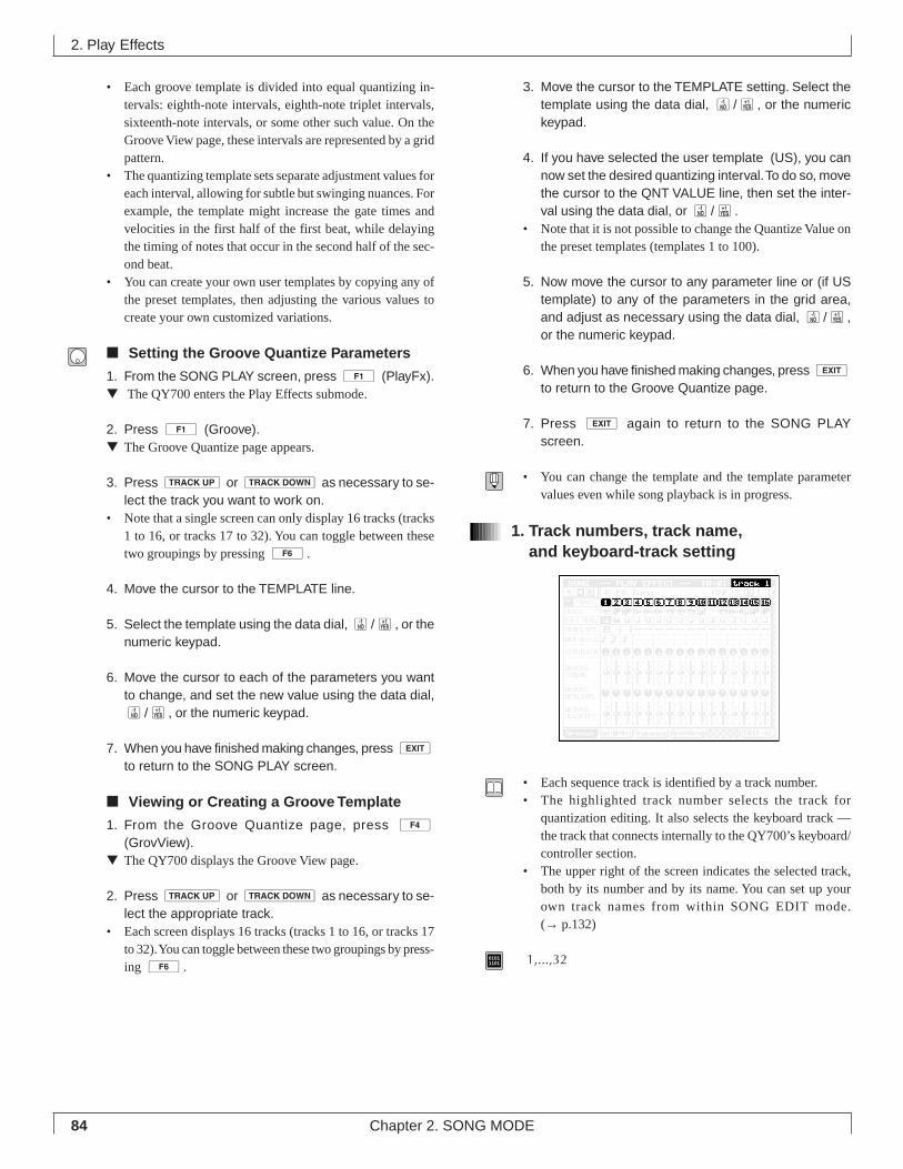
84 Chapter 2. SONG MODE
• Each groove template is divided into equal quantizing in-tervals: eighth-note intervals, eighth-note triplet intervals,sixteenth-note intervals, or some other such value. On theGroove View page, these intervals are represented by a gridpattern.
• The quantizing template sets separate adjustment values foreach interval, allowing for subtle but swinging nuances. Forexample, the template might increase the gate times andvelocities in the first half of the first beat, while delayingthe timing of notes that occur in the second half of the sec-ond beat.
• You can create your own user templates by copying any ofthe preset templates, then adjusting the various values tocreate your own customized variations.
■ Setting the Groove Quantize Parameters
1. From the SONG PLAY screen, press 1 (PlayFx).▼ The QY700 enters the Play Effects submode.
2. Press 1 (Groove).▼ The Groove Quantize page appears.
3. Press u or d as necessary to se-lect the track you want to work on.
• Note that a single screen can only display 16 tracks (tracks1 to 16, or tracks 17 to 32). You can toggle between thesetwo groupings by pressing 6.
4. Move the cursor to the TEMPLATE line.
5. Select the template using the data dial, n/y, or thenumeric keypad.
6. Move the cursor to each of the parameters you wantto change, and set the new value using the data dial,n/y, or the numeric keypad.
7. When you have finished making changes, press eto return to the SONG PLAY screen.
■ Viewing or Creating a Groove Template
1. From the Groove Quantize page, press 4(GrovView).
▼ The QY700 displays the Groove View page.
2. Press u or d as necessary to se-lect the appropriate track.
• Each screen displays 16 tracks (tracks 1 to 16, or tracks 17to 32). You can toggle between these two groupings by press-ing 6.
3. Move the cursor to the TEMPLATE setting. Select thetemplate using the data dial, n/y, or the numerickeypad.
4. If you have selected the user template (US), you cannow set the desired quantizing interval. To do so, movethe cursor to the QNT VALUE line, then set the inter-val using the data dial, or n/y.
• Note that it is not possible to change the Quantize Value onthe preset templates (templates 1 to 100).
5. Now move the cursor to any parameter line or (if UStemplate) to any of the parameters in the grid area,and adjust as necessary using the data dial, n/y,or the numeric keypad.
6. When you have finished making changes, press eto return to the Groove Quantize page.
7. Press e again to return to the SONG PLAYscreen.
• You can change the template and the template parametervalues even while song playback is in progress.
1. Track numbers, track name,and keyboard-track setting
• Each sequence track is identified by a track number.• The highlighted track number selects the track for
quantization editing. It also selects the keyboard track —the track that connects internally to the QY700’s keyboard/controller section.
• The upper right of the screen indicates the selected track,both by its number and by its name. You can set up yourown track names from within SONG EDIT mode.(→ p.132)
01011101 1,...,32
2. Play Effects
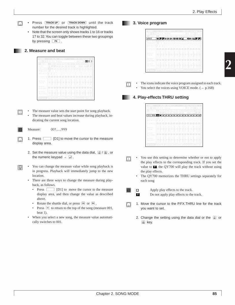
85Chapter 2. SONG MODE
2
• Press u or d until the tracknumber for the desired track is highlighted.
• Note that the screen only shows tracks 1 to 16 or tracks17 to 32. You can toggle between these two groupingsby pressing 6.
2. Measure and beat
• The measure value sets the start point for song playback.• The measure and beat values increase during playback, in-
dicating the current song location.
01011101 Measure: 001,...,999
1. Press d [D1] to move the cursor to the measuredisplay area.
2. Set the measure value using the data dial, n/y, orthe numeric keypad → e.
• You can change the measure value while song playback isin progress. Playback will immediately jump to the newlocation.
• There are three ways to change the measure during play-back, as follows.• Press d [D1] to move the cursor to the measure
display area, and then change the value as describedabove.
• Rotate the shuttle dial, or press r or f.• Press t to return to the top of the song (measure 001,
beat 1).• When you select a new song, the measure value automati-
cally switches to 001.
3. Voice program
• The icons indicate the voice program assigned to each track.• You select the voices using VOICE mode. (→ p.168)
4. Play-effects THRU setting
• You use this setting to determine whether or not to applythe play effects to the corresponding track. If you set thevalue to , the QY700 will play the track without usingthe play effects.
• The QY700 memorizes the THRU settings separately foreach song
01011101 Apply play effects to the track.
Do not apply play effects to the track.
1. Move the cursor to the P.FX.THRU line for the trackyou want to set.
2. Change the setting using the data dial or the n ory key.
2. Play Effects
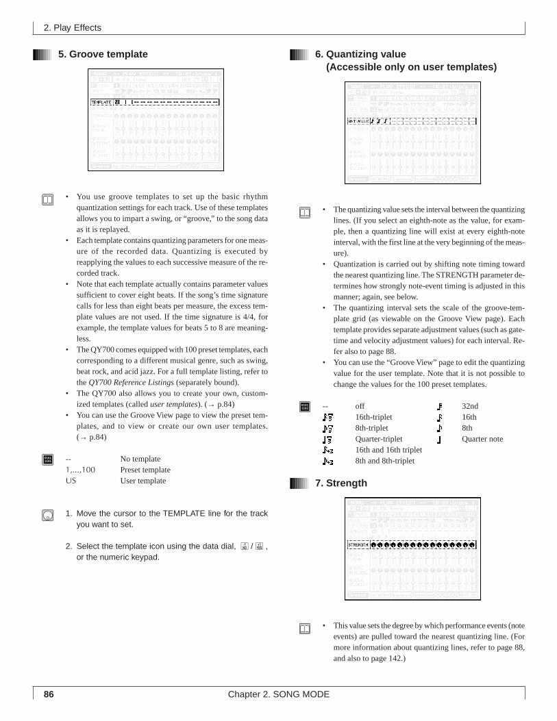
86 Chapter 2. SONG MODE
5. Groove template
• You use groove templates to set up the basic rhythmquantization settings for each track. Use of these templatesallows you to impart a swing, or “groove,” to the song dataas it is replayed.
• Each template contains quantizing parameters for one meas-ure of the recorded data. Quantizing is executed byreapplying the values to each successive measure of the re-corded track.
• Note that each template actually contains parameter valuessufficient to cover eight beats. If the song’s time signaturecalls for less than eight beats per measure, the excess tem-plate values are not used. If the time signature is 4/4, forexample, the template values for beats 5 to 8 are meaning-less.
• The QY700 comes equipped with 100 preset templates, eachcorresponding to a different musical genre, such as swing,beat rock, and acid jazz. For a full template listing, refer tothe QY700 Reference Listings (separately bound).
• The QY700 also allows you to create your own, custom-ized templates (called user templates). (→ p.84)
• You can use the Groove View page to view the preset tem-plates, and to view or create our own user templates.(→ p.84)
01011101 -- No template
1,...,100 Preset templateUS User template
1. Move the cursor to the TEMPLATE line for the trackyou want to set.
2. Select the template icon using the data dial, n/y,or the numeric keypad.
6. Quantizing value(Accessible only on user templates)
• The quantizing value sets the interval between the quantizinglines. (If you select an eighth-note as the value, for exam-ple, then a quantizing line will exist at every eighth-noteinterval, with the first line at the very beginning of the meas-ure).
• Quantization is carried out by shifting note timing towardthe nearest quantizing line. The STRENGTH parameter de-termines how strongly note-event timing is adjusted in thismanner; again, see below.
• The quantizing interval sets the scale of the groove-tem-plate grid (as viewable on the Groove View page). Eachtemplate provides separate adjustment values (such as gate-time and velocity adjustment values) for each interval. Re-fer also to page 88.
• You can use the “Groove View” page to edit the quantizingvalue for the user template. Note that it is not possible tochange the values for the 100 preset templates.
01011101 -- off 32nd
16th-triplet 16th8th-triplet 8thQuarter-triplet Quarter note16th and 16th triplet8th and 8th-triplet
7. Strength
• This value sets the degree by which performance events (noteevents) are pulled toward the nearest quantizing line. (Formore information about quantizing lines, refer to page 88,and also to page 142.)
2. Play Effects
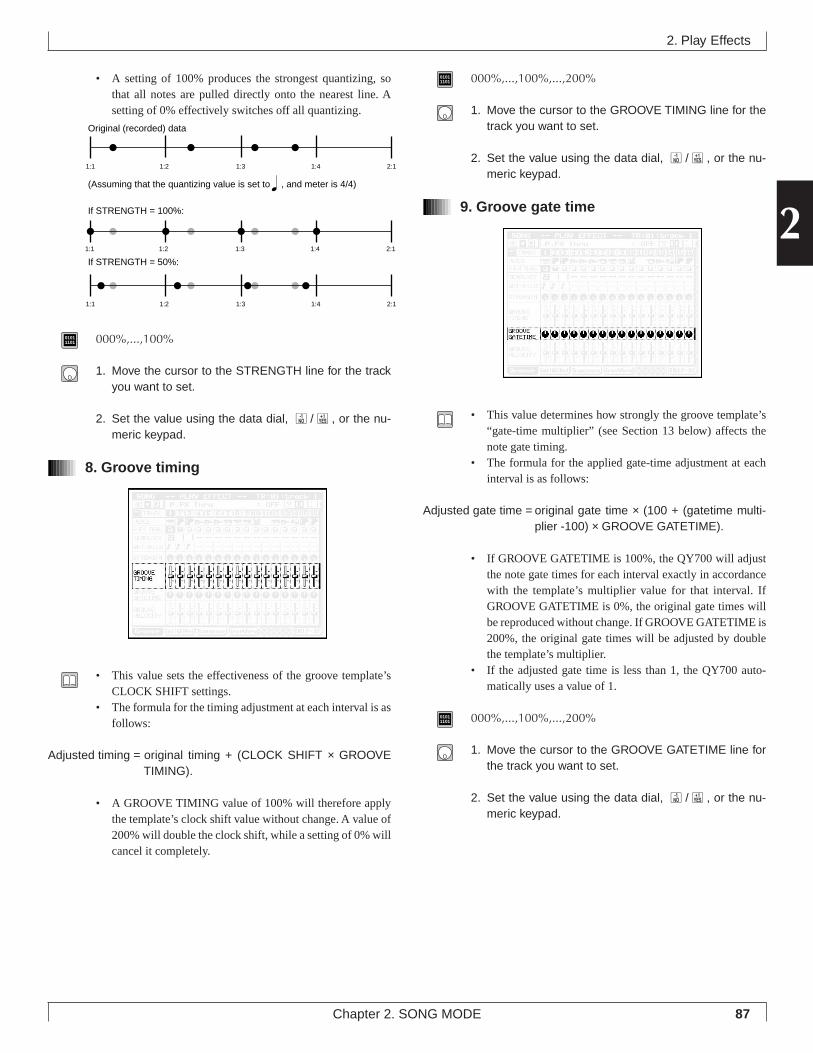
87Chapter 2. SONG MODE
2
• A setting of 100% produces the strongest quantizing, sothat all notes are pulled directly onto the nearest line. Asetting of 0% effectively switches off all quantizing.
01011101 000%,...,100%
1. Move the cursor to the STRENGTH line for the trackyou want to set.
2. Set the value using the data dial, n/y, or the nu-meric keypad.
8. Groove timing
• This value sets the effectiveness of the groove template’sCLOCK SHIFT settings.
• The formula for the timing adjustment at each interval is asfollows:
Adjusted timing = original timing + (CLOCK SHIFT × GROOVETIMING).
• A GROOVE TIMING value of 100% will therefore applythe template’s clock shift value without change. A value of200% will double the clock shift, while a setting of 0% willcancel it completely.
01011101 000%,...,100%,...,200%
1. Move the cursor to the GROOVE TIMING line for thetrack you want to set.
2. Set the value using the data dial, n/y, or the nu-meric keypad.
9. Groove gate time
• This value determines how strongly the groove template’s“gate-time multiplier” (see Section 13 below) affects thenote gate timing.
• The formula for the applied gate-time adjustment at eachinterval is as follows:
Adjusted gate time = original gate time × (100 + (gatetime multi-plier -100) × GROOVE GATETIME).
• If GROOVE GATETIME is 100%, the QY700 will adjustthe note gate times for each interval exactly in accordancewith the template’s multiplier value for that interval. IfGROOVE GATETIME is 0%, the original gate times willbe reproduced without change. If GROOVE GATETIME is200%, the original gate times will be adjusted by doublethe template’s multiplier.
• If the adjusted gate time is less than 1, the QY700 auto-matically uses a value of 1.
01011101 000%,...,100%,...,200%
1. Move the cursor to the GROOVE GATETIME line forthe track you want to set.
2. Set the value using the data dial, n/y, or the nu-meric keypad.
2. Play Effects
Original (recorded) data
(Assuming that the quantizing value is set to
If STRENGTH = 50%:
If STRENGTH = 100%:
, and meter is 4/4)
1:1 1:2 1:3 1:4 2:1
1:1 1:2 1:3 1:4 2:1
1:1 1:2 1:3 1:4 2:1
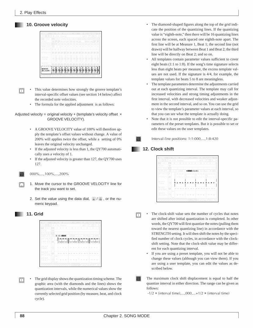
88 Chapter 2. SONG MODE
10. Groove velocity
• This value determines how strongly the groove template’sinterval-specific offset values (see section 14 below) affectthe recorded note velocities.
• The formula for the applied adjustment is as follows:
Adjusted velocity = original velocity + (template’s velocity offset ×GROOVE VELOCITY).
• A GROOVE VELOCITY value of 100% will therefore ap-ply the template’s offset values without change. A value of200% will applies twice the offset, while a setting of 0%leaves the original velocity unchanged.
• If the adjusted velocity is less than 1, the QY700 automati-cally uses a velocity of 1.
• If the adjusted velocity is greater than 127, the QY700 uses127.
01011101 000%,...,100%,...,200%
1. Move the cursor to the GROOVE VELOCITY line forthe track you want to set.
2. Set the value using the data dial, n/y, or the nu-meric keypad.
11. Grid
• The grid display shows the quantization timing scheme. Thegraphic area (with the diamonds and the lines) shows thequantization intervals, while the numerical values show thecurrently selected grid position (by measure, beat, and clockcycle).
• The diamond-shaped figures along the top of the grid indi-cate the position of the quantizing lines. If the quantizingvalue is “eighth-note,” then there will be 16 quantizing linesacross the screen, each spaced one eighth-note apart. Thefirst line will be at Measure 1, Beat 1; the second line (notdrawn) will be halfway between Beat 1 and Beat 2; the thirdline will be directly on Beat 2; and so on.
• All templates contain parameter values sufficient to covereight beats (1:1 to 1:8). If the song’s time signature selectsless than eight beats per measure, the excess template val-ues are not used. If the signature is 4/4, for example, thetemplate values for beats 5 to 8 are meaningless.
• The template parameters determine the adjustments carriedout at each quantizing interval. The template may call forincreased velocities and strong timing adjustments in thefirst interval, with decreased velocities and weaker adjust-ment in the second interval, and so on. You can use the gridto view the template’s parameter values at each interval, sothat you can see what the template is actually doing.
• Note that it is not possible to edit the interval-specific pa-rameters of the preset templates. But it is possible to set oredit these values on the user templates.
01011101 Interval-line positions: 1:1:000,...,1:8:420
12. Clock shift
• The clock-shift value sets the number of cycles that notesare shifted after initial quantization is completed. In otherwords, the QY700 will first quantize the notes (pulling themtoward the nearest quantizing line) in accordance with theSTRENGTH setting. It will then shift the notes by the speci-fied number of clock cycles, in accordance with the clock-shift setting. Note that the clock-shift value may be differ-ent for each quantizing interval.
• If you are using a preset template, you will not be able tochange these values (although you can view them). If youare using a user template, you can edit the values as de-scribed below.
01011101 The maximum clock shift displacement is equal to half the
quantize interval in either direction. The range can be given asfollows: -1/2 × (interval time),...,000,...+1/2 × (interval time)
2. Play Effects
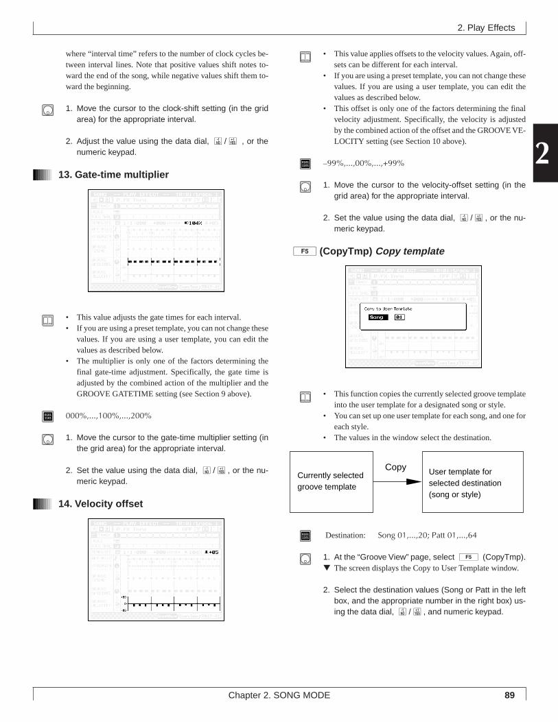
89Chapter 2. SONG MODE
2
where “interval time” refers to the number of clock cycles be-tween interval lines. Note that positive values shift notes to-ward the end of the song, while negative values shift them to-ward the beginning.
1. Move the cursor to the clock-shift setting (in the gridarea) for the appropriate interval.
2. Adjust the value using the data dial, n/y , or thenumeric keypad.
13. Gate-time multiplier
• This value adjusts the gate times for each interval.• If you are using a preset template, you can not change these
values. If you are using a user template, you can edit thevalues as described below.
• The multiplier is only one of the factors determining thefinal gate-time adjustment. Specifically, the gate time isadjusted by the combined action of the multiplier and theGROOVE GATETIME setting (see Section 9 above).
01011101 000%,...,100%,...,200%
1. Move the cursor to the gate-time multiplier setting (inthe grid area) for the appropriate interval.
2. Set the value using the data dial, n/y, or the nu-meric keypad.
14. Velocity offset
• This value applies offsets to the velocity values. Again, off-sets can be different for each interval.
• If you are using a preset template, you can not change thesevalues. If you are using a user template, you can edit thevalues as described below.
• This offset is only one of the factors determining the finalvelocity adjustment. Specifically, the velocity is adjustedby the combined action of the offset and the GROOVE VE-LOCITY setting (see Section 10 above).
01011101 –99%,...,00%,...,+99%
1. Move the cursor to the velocity-offset setting (in thegrid area) for the appropriate interval.
2. Set the value using the data dial, n/y, or the nu-meric keypad.
5 (CopyTmp) Copy template
• This function copies the currently selected groove templateinto the user template for a designated song or style.
• You can set up one user template for each song, and one foreach style.
• The values in the window select the destination.
01011101 Destination: Song 01,...,20; Patt 01,...,64
1. At the “Groove View” page, select 5 (CopyTmp).▼ The screen displays the Copy to User Template window.
2. Select the destination values (Song or Patt in the leftbox, and the appropriate number in the right box) us-ing the data dial, n/y, and numeric keypad.
2. Play Effects
Currently selected groove template
User template for selected destination (song or style)
Copy
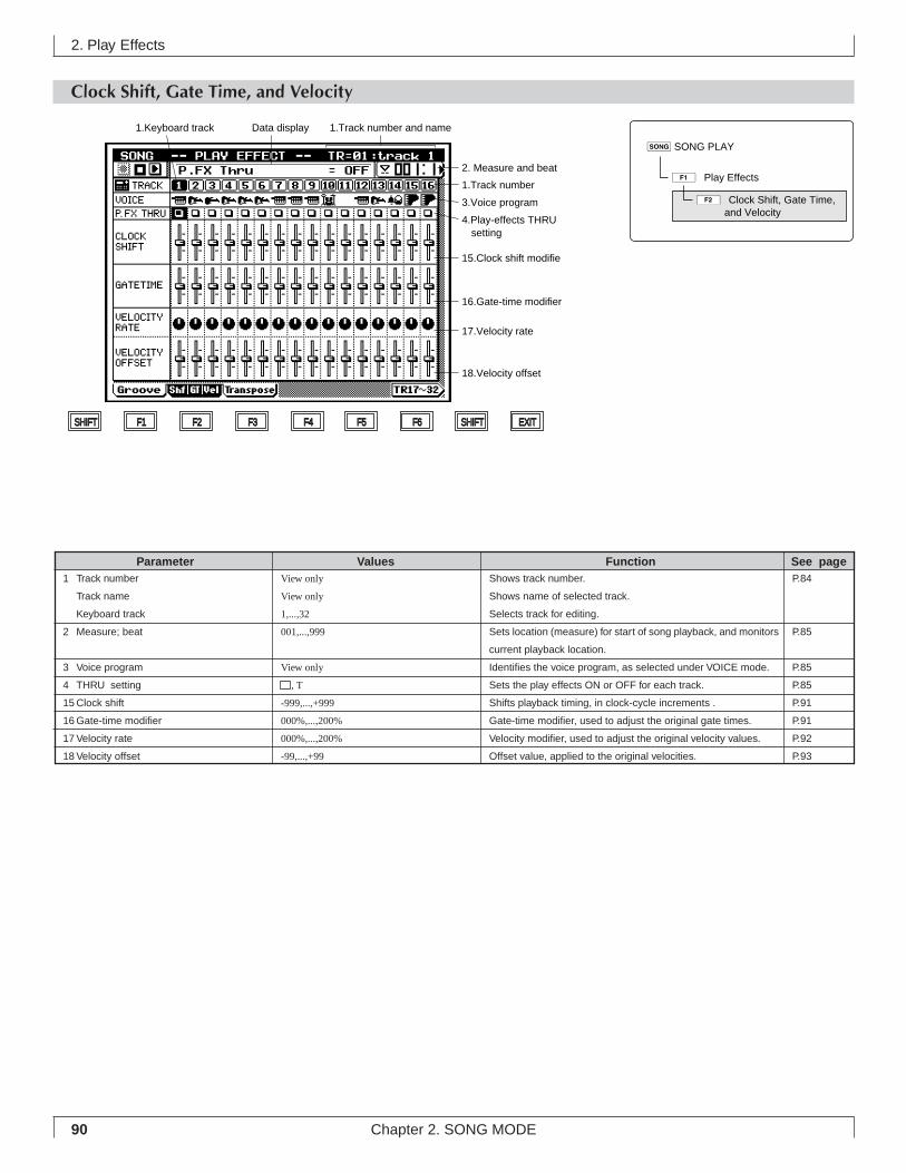
90 Chapter 2. SONG MODE
Clock Shift, Gate Time, and Velocity
2. Play Effects
Shows track number.
Shows name of selected track.
Selects track for editing.
Sets location (measure) for start of song playback, and monitors
current playback location.
Identifies the voice program, as selected under VOICE mode.
Sets the play effects ON or OFF for each track.
Shifts playback timing, in clock-cycle increments .
Gate-time modifier, used to adjust the original gate times.
Velocity modifier, used to adjust the original velocity values.
Offset value, applied to the original velocities.
View only
View only
1,...,32
001,...,999
View only
, T
-999,...,+999
000%,...,200%
000%,...,200%
-99,...,+99
1 Track number
Track name
Keyboard track
2 Measure; beat
3 Voice program
4 THRU setting
15 Clock shift
16 Gate-time modifier
17 Velocity rate
18 Velocity offset
Parameter Values Function See pageP.84
P.85
P.85
P.85
P.91
P.91
P.92
P.93
SHIFT F1 F2 F3 F4 F5 F6 SHIFT EXIT
Data display1.Keyboard track 1.Track number and name
1.Track number
2. Measure and beat
15.Clock shift modifie
4.Play-effects THRU setting
16.Gate-time modifier
17.Velocity rate
18.Velocity offset
3.Voice program
sSONG PLAY
1ÊPlay Effects
2ÊClock Shift, Gate Time,and Velocity
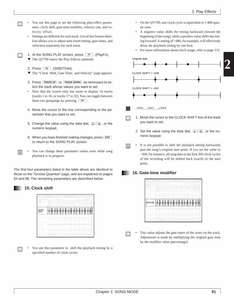
91Chapter 2. SONG MODE
2
• You use this page to set the following play-effect param-eters: clock shift, gate-time modifier, velocity rate, and ve-locity offset.
• Settings are different for each track. Use of this feature there-fore allows you to adjust note-event timing, gate times, andvelocities separately for each track.
1. At the SONG PLAY screen, press 1 (PlayFx).▼ The QY700 enters the Play Effects submode.
2. Press 2 (Shf|GT|Vel).▼ The “Clock Shift, Gate Time, and Velocity” page appears.
3. Press u or d as necessary to se-lect the track whose values you want to set.
• Note that the screen only has room to display 16 tracks(tracks 1 to 16, or tracks 17 to 32). You can toggle betweenthese two groupings by pressing 6.
4. Move the cursor to the line corresponding to the pa-rameter that you want to set.
5. Change the value using the data dial, n/y, or thenumeric keypad.
6. When you have finished making changes, presseto return to the SONG PLAY screen.
• You can change these parameter values even while songplayback is in progress.
The first four parameters listed in the table above are identical tothose on the “Groove Quantize” page, and are explained on pages84 and 85. The remaining parameters are described below.
15. Clock shift
• You use this parameter to shift the playback timing by aspecified number of clock cycles.
• On the QY700, one clock cycle is equivalent to 1/480 quar-ter note.
• A negative value shifts the timing backward (toward thebeginning of the song), while a positive value shifts the tim-ing forward. A setting of +480, for example, will effectivelydelay the playback timing by one beat.
• For more information about clock usage, refer to page 131.
01011101 –999,...,000,...,+999
1. Move the cursor to the CLOCK SHIFT line of the trackyou want to set.
2. Set the value using the data dial, n/y, or the nu-meric keypad.
• It is not possible to shift the playback timing backwardspast the song’s original start point. If you set the value to–300, for instance, all song data in the first 300 clock cyclesof the recording will be shifted back exactly to the startpoint.
16. Gate-time modifier
• This value adjusts the gate times of the notes on the track.Adjustment is made by multiplying the original gate timeby the modifier value (percentage).
2. Play Effects
Original data
CLOCK SHIFT = +240
CLOCK SHIFT = -240
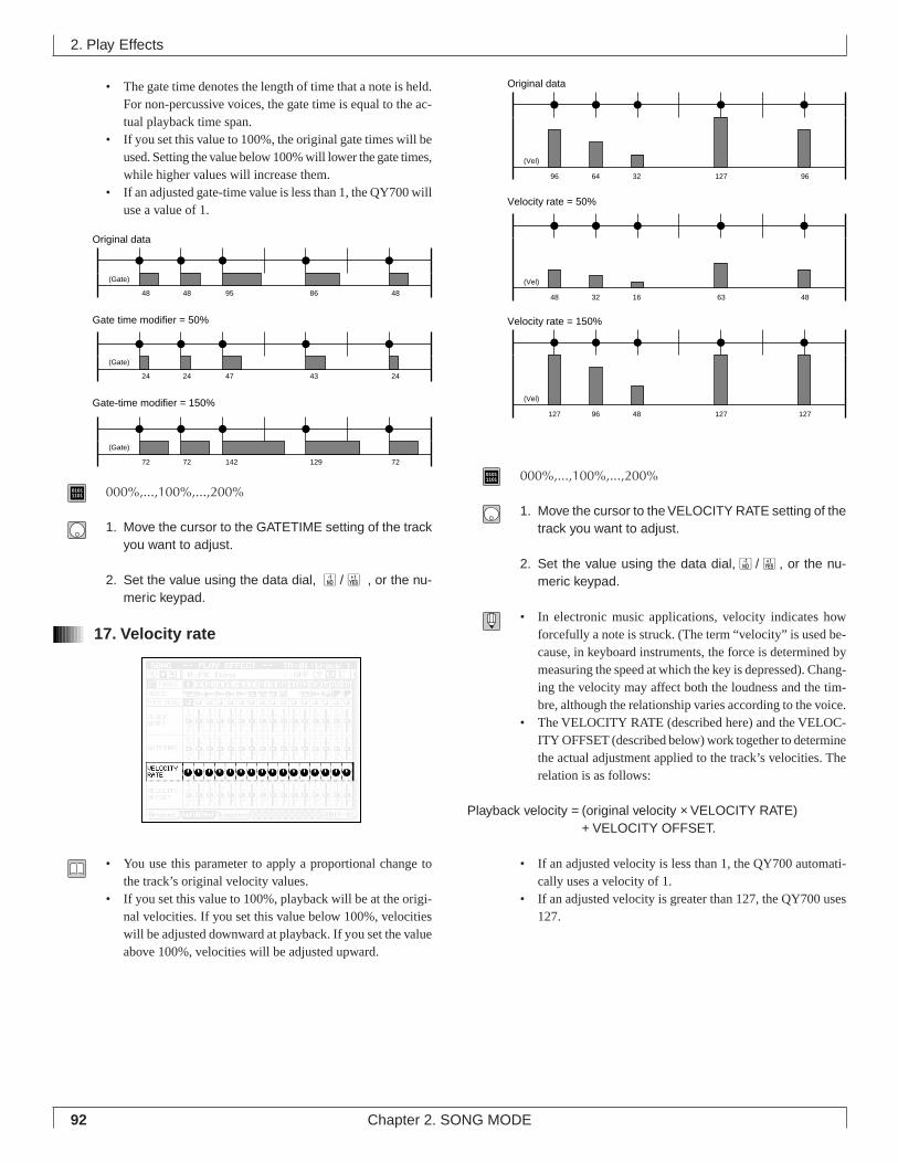
92 Chapter 2. SONG MODE
• The gate time denotes the length of time that a note is held.For non-percussive voices, the gate time is equal to the ac-tual playback time span.
• If you set this value to 100%, the original gate times will beused. Setting the value below 100% will lower the gate times,while higher values will increase them.
• If an adjusted gate-time value is less than 1, the QY700 willuse a value of 1.
01011101 000%,...,100%,...,200%
1. Move the cursor to the GATETIME setting of the trackyou want to adjust.
2. Set the value using the data dial, n/y , or the nu-meric keypad.
17. Velocity rate
• You use this parameter to apply a proportional change tothe track’s original velocity values.
• If you set this value to 100%, playback will be at the origi-nal velocities. If you set this value below 100%, velocitieswill be adjusted downward at playback. If you set the valueabove 100%, velocities will be adjusted upward.
01011101 000%,...,100%,...,200%
1. Move the cursor to the VELOCITY RATE setting of thetrack you want to adjust.
2. Set the value using the data dial,n/y, or the nu-meric keypad.
• In electronic music applications, velocity indicates howforcefully a note is struck. (The term “velocity” is used be-cause, in keyboard instruments, the force is determined bymeasuring the speed at which the key is depressed). Chang-ing the velocity may affect both the loudness and the tim-bre, although the relationship varies according to the voice.
• The VELOCITY RATE (described here) and the VELOC-ITY OFFSET (described below) work together to determinethe actual adjustment applied to the track’s velocities. Therelation is as follows:
Playback velocity = (original velocity × VELOCITY RATE)+ VELOCITY OFFSET.
• If an adjusted velocity is less than 1, the QY700 automati-cally uses a velocity of 1.
• If an adjusted velocity is greater than 127, the QY700 uses127.
2. Play Effects
Original data
Velocity rate = 50%
(Vel)
96 64 32 127 96
Velocity rate = 150%
(Vel)
127 96 48 127 127
(Vel)
48 32 16 63 48
Original data
Gate time modifier = 50%
Gate-time modifier = 150%
(Gate)
(Gate)
(Gate)
48 48 95 86 48
24 24 47 43 24
72 72 142 129 72
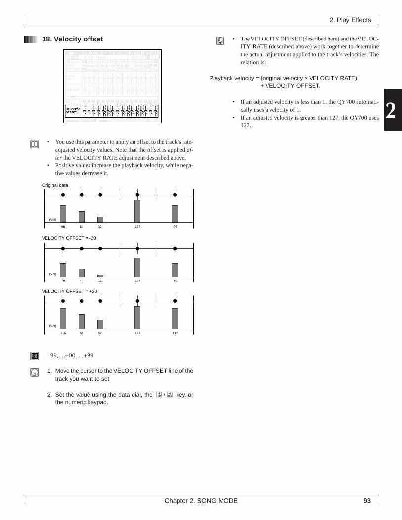
93Chapter 2. SONG MODE
2
18. Velocity offset
• You use this parameter to apply an offset to the track’s rate-adjusted velocity values. Note that the offset is applied af-ter the VELOCITY RATE adjustment described above.
• Positive values increase the playback velocity, while nega-tive values decrease it.
01011101 –99,...,+00,...,+99
1. Move the cursor to the VELOCITY OFFSET line of thetrack you want to set.
2. Set the value using the data dial, the n/y key, orthe numeric keypad.
• The VELOCITY OFFSET (described here) and the VELOC-ITY RATE (described above) work together to determinethe actual adjustment applied to the track’s velocities. Therelation is:
Playback velocity = (original velocity × VELOCITY RATE)+ VELOCITY OFFSET.
• If an adjusted velocity is less than 1, the QY700 automati-cally uses a velocity of 1.
• If an adjusted velocity is greater than 127, the QY700 uses127.
2. Play Effects
Original data
VELOCITY OFFSET = -20
(Vel)
96 64 32 127 96
VELOCITY OFFSET = +20
(Vel)
116 84 52 127 116
(Vel)
76 44 12 107 76
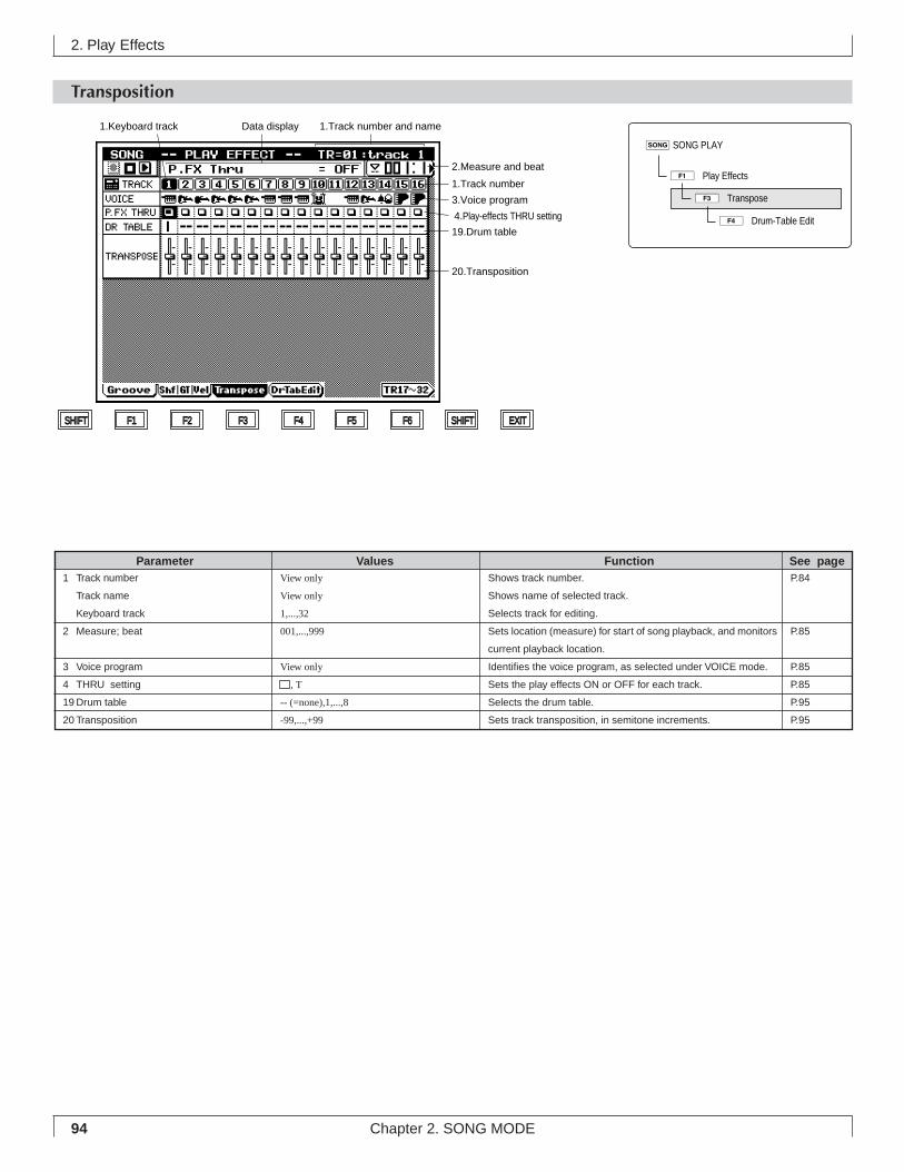
94 Chapter 2. SONG MODE
2. Play Effects
Transposition
Shows track number.
Shows name of selected track.
Selects track for editing.
Sets location (measure) for start of song playback, and monitors
current playback location.
Identifies the voice program, as selected under VOICE mode.
Sets the play effects ON or OFF for each track.
Selects the drum table.
Sets track transposition, in semitone increments.
View only
View only
1,...,32
001,...,999
View only
, T
-- (=none),1,...,8
-99,...,+99
1 Track number
Track name
Keyboard track
2 Measure; beat
3 Voice program
4 THRU setting
19 Drum table
20 Transposition
Parameter Values Function See pageP.84
P.85
P.85
P.85
P.95
P.95
Data display1.Keyboard track 1.Track number and name
1.Track number
2.Measure and beat
20.Transposition
19.Drum table
4.Play-effects THRU setting
3.Voice program
SHIFT F1 F2 F3 F4 F5 F6 SHIFT EXIT
sSONG PLAY
1ÊPlay Effects
3ÊTranspose
4ÊDrum-Table Edit
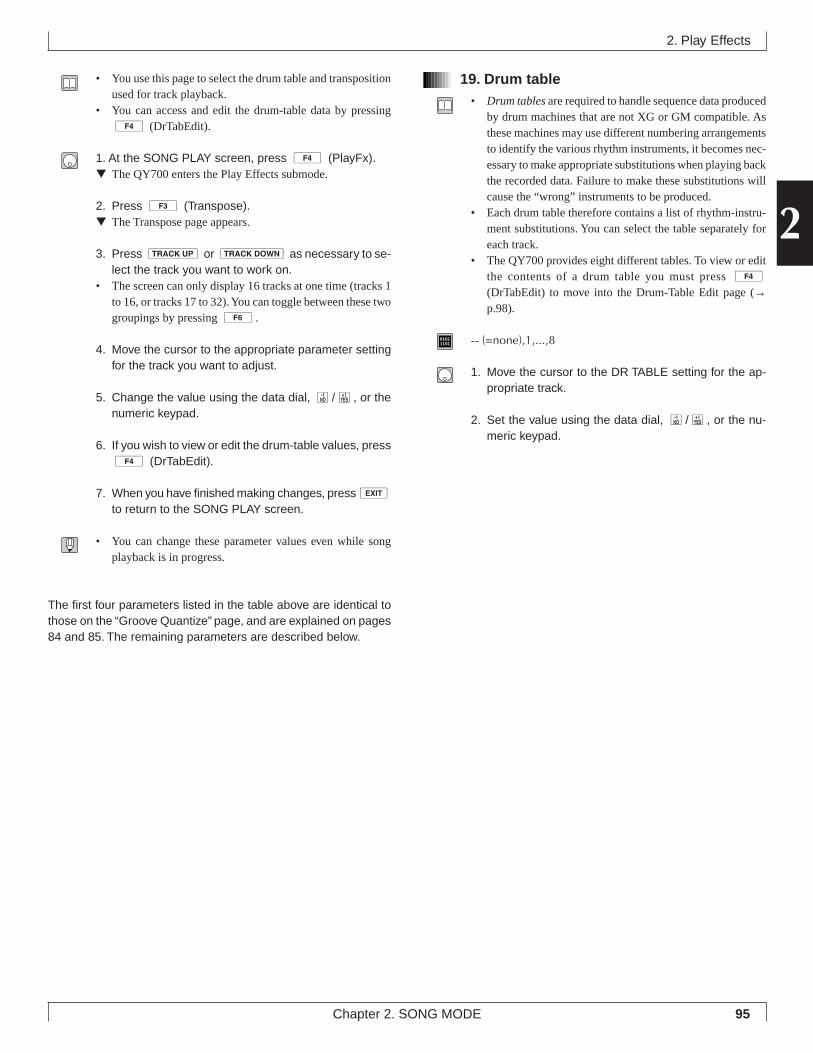
95Chapter 2. SONG MODE
2
• You use this page to select the drum table and transpositionused for track playback.
• You can access and edit the drum-table data by pressing4 (DrTabEdit).
1. At the SONG PLAY screen, press 4 (PlayFx).▼ The QY700 enters the Play Effects submode.
2. Press 3 (Transpose).▼ The Transpose page appears.
3. Press u or d as necessary to se-lect the track you want to work on.
• The screen can only display 16 tracks at one time (tracks 1to 16, or tracks 17 to 32). You can toggle between these twogroupings by pressing 6.
4. Move the cursor to the appropriate parameter settingfor the track you want to adjust.
5. Change the value using the data dial, n/y, or thenumeric keypad.
6. If you wish to view or edit the drum-table values, press4 (DrTabEdit).
7. When you have finished making changes, presseto return to the SONG PLAY screen.
• You can change these parameter values even while songplayback is in progress.
The first four parameters listed in the table above are identical tothose on the “Groove Quantize” page, and are explained on pages84 and 85. The remaining parameters are described below.
19. Drum table• Drum tables are required to handle sequence data produced
by drum machines that are not XG or GM compatible. Asthese machines may use different numbering arrangementsto identify the various rhythm instruments, it becomes nec-essary to make appropriate substitutions when playing backthe recorded data. Failure to make these substitutions willcause the “wrong” instruments to be produced.
• Each drum table therefore contains a list of rhythm-instru-ment substitutions. You can select the table separately foreach track.
• The QY700 provides eight different tables. To view or editthe contents of a drum table you must press 4
(DrTabEdit) to move into the Drum-Table Edit page (→p.98).
01011101 -- (=none),1,...,8
1. Move the cursor to the DR TABLE setting for the ap-propriate track.
2. Set the value using the data dial, n/y, or the nu-meric keypad.
2. Play Effects
96 Chapter 2. SONG MODE
20. Transposition• You can use this feature to change the key (alter the pitch)
of any track. You can set transposition separately for eachtrack.
• Transposition is in semitone increments. Setting the valueto +12, therefore, will raise the pitch of all notes on thetrack by exactly one octave. A setting of -12 would drop thepitch by exactly one octave.
01011101 –99,...,+99
1. Move the cursor to the TRANSPOSE setting for thetrack you want to transpose.
2. Set the value using the data dial, n/y, or the nu-meric keypad.
2. Play Effects
97Chapter 2. SONG MODE
2
Drum Table Edit
2. Play Effects
Shows track number.
Shows name of selected track.
Selects track for editing.
Sets location (measure) for start of song playback, and monitors
current playback location.
Identifies the voice program, as selected under VOICE mode.
Sets the play effects ON or OFF for each track.
Selects the drum table.
List of drum-voice replacements.
Adjusts the velocity of the replacement voice. This parameter
allows you to correct for volume imbalance that may be caused
by the replacement.
View only
View only
1,...,32
001,...,999
View only
View only
, T
-- (=none),1,...,8
000%,...,100%,...,200%
1 Track number
Track name
Keyboard track
2 Measure
Beat
3 Voice program
4 THRU setting
19 Drum table
21 Replacement list
22 Velocity rate
Parameter Values Function See pageP.84
P.85
P.85
P.85
P.95
P.98
P.98
Data display1.Keyboard track 1.Track number and name
1.Track number
2.Measure and beat
19.Drum table
4. Play-effects THRU setting
3.Voice program
22.Velocity rate
21.Replacement list
SHIFT F1 F2 F3 F4 F5 F6 SHIFT EXIT
sSONG PLAY
1ÊPlay Effects
3ÊTranspose
4ÊDrum-Table Edit
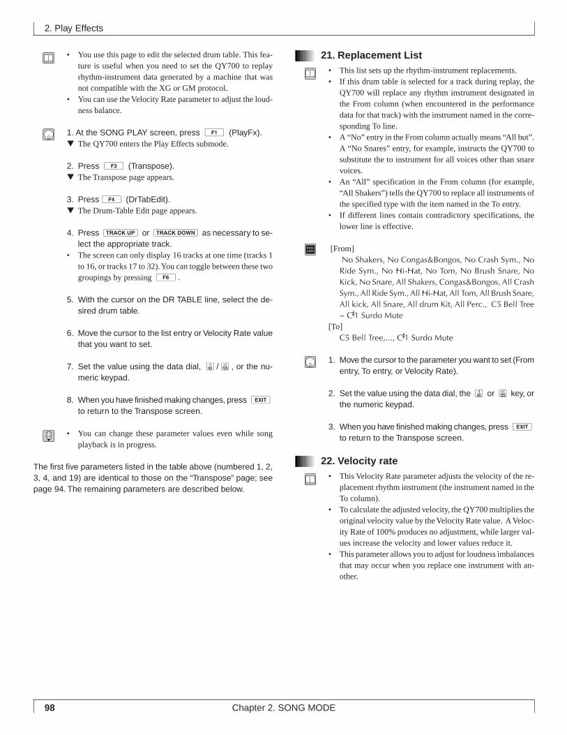
98 Chapter 2. SONG MODE
• You use this page to edit the selected drum table. This fea-ture is useful when you need to set the QY700 to replayrhythm-instrument data generated by a machine that wasnot compatible with the XG or GM protocol.
• You can use the Velocity Rate parameter to adjust the loud-ness balance.
1. At the SONG PLAY screen, press 1 (PlayFx).▼ The QY700 enters the Play Effects submode.
2. Press 3 (Transpose).▼ The Transpose page appears.
3. Press4 (DrTabEdit).▼ The Drum-Table Edit page appears.
4. Press u or d as necessary to se-lect the appropriate track.
• The screen can only display 16 tracks at one time (tracks 1to 16, or tracks 17 to 32). You can toggle between these twogroupings by pressing 6.
5. With the cursor on the DR TABLE line, select the de-sired drum table.
6. Move the cursor to the list entry or Velocity Rate valuethat you want to set.
7. Set the value using the data dial, n/y, or the nu-meric keypad.
8. When you have finished making changes, press eto return to the Transpose screen.
• You can change these parameter values even while songplayback is in progress.
The first five parameters listed in the table above (numbered 1, 2,3, 4, and 19) are identical to those on the “Transpose” page; seepage 94. The remaining parameters are described below.
21. Replacement List• This list sets up the rhythm-instrument replacements.• If this drum table is selected for a track during replay, the
QY700 will replace any rhythm instrument designated inthe From column (when encountered in the performancedata for that track) with the instrument named in the corre-sponding To line.
• A “No” entry in the From column actually means “All but”.A “No Snares” entry, for example, instructs the QY700 tosubstitute the to instrument for all voices other than snarevoices.
• An “All” specification in the From column (for example,“All Shakers”) tells the QY700 to replace all instruments ofthe specified type with the item named in the To entry.
• If different lines contain contradictory specifications, thelower line is effective.
01011101 [From]
No Shakers, No Congas&Bongos, No Crash Sym., NoRide Sym., No Hi-Hat, No Tom, No Brush Snare, NoKick, No Snare, All Shakers, Congas&Bongos, All CrashSym., All Ride Sym., All Hi-Hat, All Tom, All Brush Snare,All kick, All Snare, All drum Kit, All Perc., C5 Bell Tree~ C#1 Surdo Mute
[To]C5 Bell Tree,..., C#1 Surdo Mute
1. Move the cursor to the parameter you want to set (Fromentry, To entry, or Velocity Rate).
2. Set the value using the data dial, the n or y key, orthe numeric keypad.
3. When you have finished making changes, press eto return to the Transpose screen.
22. Velocity rate• This Velocity Rate parameter adjusts the velocity of the re-
placement rhythm instrument (the instrument named in theTo column).
• To calculate the adjusted velocity, the QY700 multiplies theoriginal velocity value by the Velocity Rate value. A Veloc-ity Rate of 100% produces no adjustment, while larger val-ues increase the velocity and lower values reduce it.
• This parameter allows you to adjust for loudness imbalancesthat may occur when you replace one instrument with an-other.
2. Play Effects
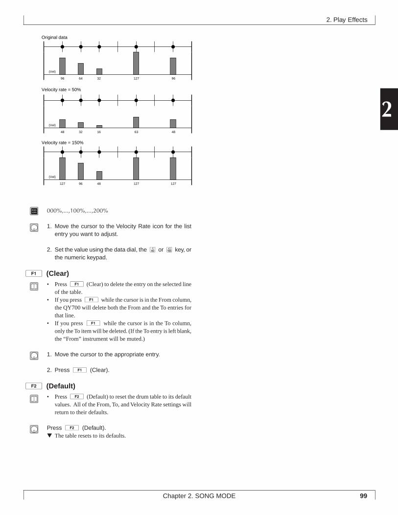
99Chapter 2. SONG MODE
2
01011101 000%,...,100%,...,200%
1. Move the cursor to the Velocity Rate icon for the listentry you want to adjust.
2. Set the value using the data dial, the n or y key, orthe numeric keypad.
1 (Clear)• Press 1 (Clear) to delete the entry on the selected line
of the table.• If you press 1 while the cursor is in the From column,
the QY700 will delete both the From and the To entries forthat line.
• If you press 1 while the cursor is in the To column,only the To item will be deleted. (If the To entry is left blank,the “From” instrument will be muted.)
1. Move the cursor to the appropriate entry.
2. Press 1 (Clear).
2 (Default)• Press 2 (Default) to reset the drum table to its default
values. All of the From, To, and Velocity Rate settings willreturn to their defaults.
Press 2 (Default).▼ The table resets to its defaults.
2. Play Effects
Original data
Velocity rate = 50%
(Vel)
96 64 32 127 96
Velocity rate = 150%
(Vel)
127 96 48 127 127
(Vel)
48 32 16 63 48
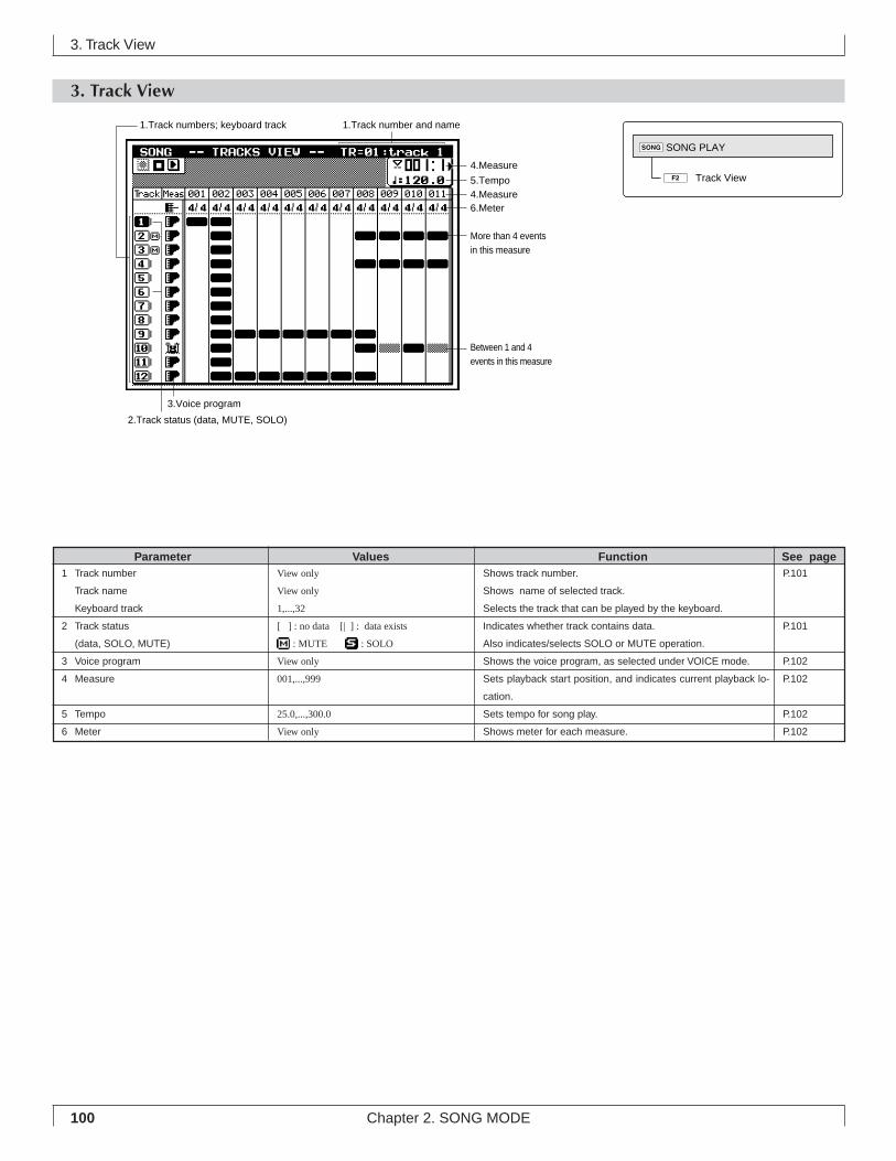
100 Chapter 2. SONG MODE
3. Track View
3. Track View
Shows track number.
Shows name of selected track.
Selects the track that can be played by the keyboard.
Indicates whether track contains data.
Also indicates/selects SOLO or MUTE operation.
Shows the voice program, as selected under VOICE mode.
Sets playback start position, and indicates current playback lo-
cation.
Sets tempo for song play.
Shows meter for each measure.
View only
View only
1,...,32
[ ] : no data [| ] : data exists
: MUTE : SOLO
View only
001,...,999
25.0,...,300.0
View only
1 Track number
Track name
Keyboard track
2 Track status
(data, SOLO, MUTE)
3 Voice program
4 Measure
5 Tempo
6 Meter
Parameter Values Function See pageP.101
P.101
P.102
P.102
P.102
P.102
3.Voice program
2.Track status (data, MUTE, SOLO)
1.Track number and name1.Track numbers; keyboard track
4.Measure
5.Tempo
6.Meter4.Measure
More than 4 events in this measure
Between 1 and 4 events in this measure
2ÊTrack View
sSONG PLAY
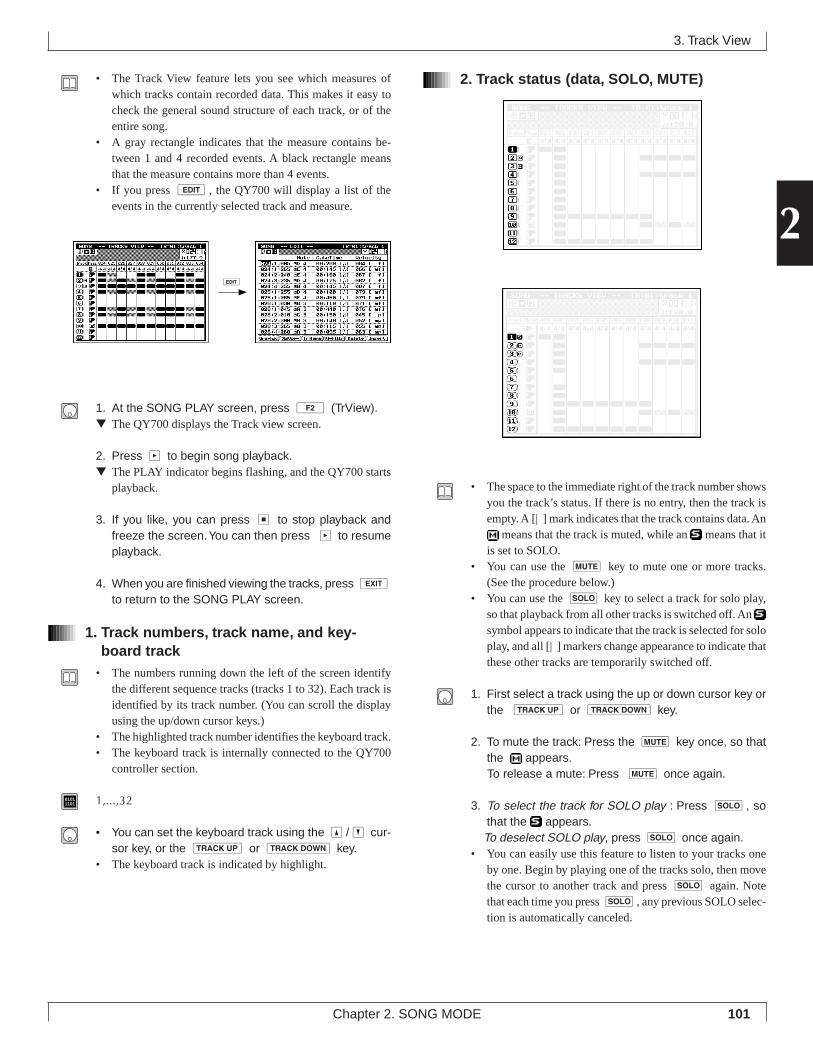
101Chapter 2. SONG MODE
2
• The Track View feature lets you see which measures ofwhich tracks contain recorded data. This makes it easy tocheck the general sound structure of each track, or of theentire song.
• A gray rectangle indicates that the measure contains be-tween 1 and 4 recorded events. A black rectangle meansthat the measure contains more than 4 events.
• If you press e, the QY700 will display a list of theevents in the currently selected track and measure.
1. At the SONG PLAY screen, press 2 (TrView).▼ The QY700 displays the Track view screen.
2. Press p to begin song playback.▼ The PLAY indicator begins flashing, and the QY700 starts
playback.
3. If you like, you can press s to stop playback andfreeze the screen. You can then press p to resumeplayback.
4. When you are finished viewing the tracks, press eto return to the SONG PLAY screen.
1. Track numbers, track name, and key-board track
• The numbers running down the left of the screen identifythe different sequence tracks (tracks 1 to 32). Each track isidentified by its track number. (You can scroll the displayusing the up/down cursor keys.)
• The highlighted track number identifies the keyboard track.• The keyboard track is internally connected to the QY700
controller section.
01011101 1,...,32
• You can set the keyboard track using the u/d cur-sor key, or the u or d key.
• The keyboard track is indicated by highlight.
2. Track status (data, SOLO, MUTE)
• The space to the immediate right of the track number showsyou the track’s status. If there is no entry, then the track isempty. A [| ] mark indicates that the track contains data. An
means that the track is muted, while an means that itis set to SOLO.
• You can use the m key to mute one or more tracks.(See the procedure below.)
• You can use the s key to select a track for solo play,so that playback from all other tracks is switched off. An symbol appears to indicate that the track is selected for soloplay, and all [| ] markers change appearance to indicate thatthese other tracks are temporarily switched off.
1. First select a track using the up or down cursor key orthe u or d key.
2. To mute the track: Press the m key once, so thatthe appears.
To release a mute: Press m once again.
3. To select the track for SOLO play : Press s, sothat the appears.
To deselect SOLO play, press s once again.• You can easily use this feature to listen to your tracks one
by one. Begin by playing one of the tracks solo, then movethe cursor to another track and press s again. Notethat each time you press s, any previous SOLO selec-tion is automatically canceled.
3. Track View
e
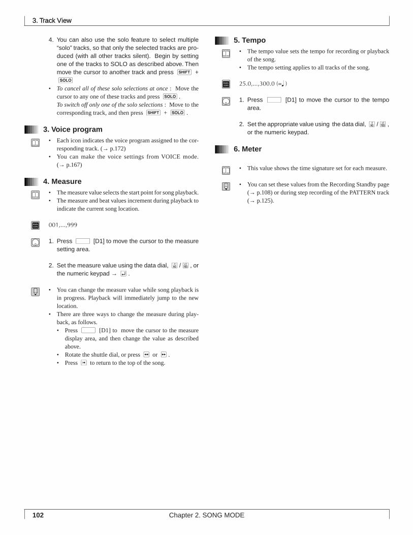
102 Chapter 2. SONG MODE
4. You can also use the solo feature to select multiple“solo” tracks, so that only the selected tracks are pro-duced (with all other tracks silent). Begin by settingone of the tracks to SOLO as described above. Thenmove the cursor to another track and press s +s
• To cancel all of these solo selections at once : Move thecursor to any one of these tracks and press s.To switch off only one of the solo selections : Move to thecorresponding track, and then press s + s.
3. Voice program• Each icon indicates the voice program assigned to the cor-
responding track. (→ p.172)• You can make the voice settings from VOICE mode.
(→ p.167)
4. Measure• The measure value selects the start point for song playback.• The measure and beat values increment during playback to
indicate the current song location.
01011101 001,...,999
1. Press d [D1] to move the cursor to the measuresetting area.
2. Set the measure value using the data dial, n/y, orthe numeric keypad → e.
• You can change the measure value while song playback isin progress. Playback will immediately jump to the newlocation.
• There are three ways to change the measure during play-back, as follows.• Press d [D1] to move the cursor to the measure
display area, and then change the value as describedabove.
• Rotate the shuttle dial, or press r or f.• Press t to return to the top of the song.
5. Tempo• The tempo value sets the tempo for recording or playback
of the song.• The tempo setting applies to all tracks of the song.
01011101 25.0,...,300.0 (=q )
1. Press d [D1] to move the cursor to the tempoarea.
2. Set the appropriate value using the data dial, n/y,or the numeric keypad.
6. Meter
• This value shows the time signature set for each measure.
• You can set these values from the Recording Standby page(→ p.108) or during step recording of the PATTERN track(→ p.125).
3. Track View3. Track View
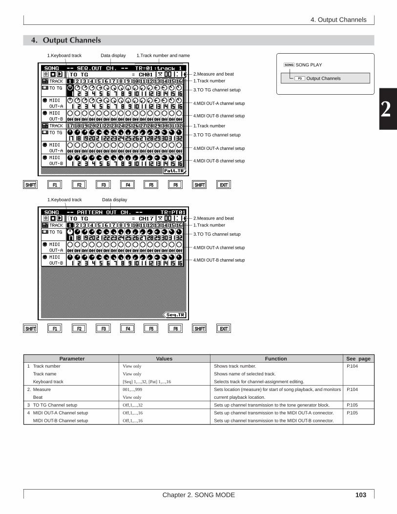
103Chapter 2. SONG MODE
2
4. Output Channels
4. Output Channels
Shows track number.
Shows name of selected track.
Selects track for channel-assignment editing.
Sets location (measure) for start of song playback, and monitors
current playback location.
Sets up channel transmission to the tone generator block.
Sets up channel transmission to the MIDI OUT-A connector.
Sets up channel transmission to the MIDI OUT-B connector.
View only
View only
[Seq] 1,...,32, [Pat] 1,...,16
001,...,999
View only
Off,1,...,32
Off,1,...,16
Off,1,...,16
1 Track number
Track name
Keyboard track
2. Measure
Beat
3 TO TG Channel setup
4 MIDI OUT-A Channel setup
MIDI OUT-B Channel setup
Parameter Values Function See pageP.104
P.104
P.105
P.105
SHIFT F1 F2 F3 F4 F5 F6 SHIFT EXIT
SHIFT F1 F2 F3 F4 F5 F6 SHIFT EXIT
4.MIDI OUT-B channel setup
4.MIDI OUT-A channel setup
3.TO TG channel setup
Data display
Data display
1.Track number
1.Keyboard track
1.Keyboard track 1.Track number and name
2.Measure and beat
4.MIDI OUT-B channel setup
4.MIDI OUT-A channel setup
3.TO TG channel setup
1.Track number
4.MIDI OUT-B channel setup
4.MIDI OUT-A channel setup
3.TO TG channel setup
1.Track number
2.Measure and beat
sSONG PLAY
3Output Channels
104 Chapter 2. SONG MODE
• You use these two pages to select the output locations foreach track. The SEQ OUT CH. page sets up channel outputfor the sequence tracks. The PATTERN OUT CH. page setsup the output for the pattern tracks.
• You use the TO TG setting to set the track’s output channelto the tone generator block.
• You use the MIDI OUT-A and MIDI OUT-B settings toassign each track to a MIDI OUT channel.
• The QY700 stores separate channel arrangements for eachsong. The assignments automatically change each time youswitch to a different song.
1. At the SONG PLAY screen, press 3 (OutCh).▼ The Output Channel setup screen appears.
2. Press u or d as necessary to se-lect the track you want to work on.
• Note that the sequence-track settings and pattern-track set-tings are shown on different pages. You can toggle betweenthe pages by pressing 6.
3. Move the cursor to the appropriate channel-settingentry.
4. Change the value using the data dial, n/y, or thenumeric keypad.
5. When you have finished making changes, presseto return to the SONG PLAY screen.
1. Track numbers, track name, and key-board track
• Each track is identified by a track number.• The highlighted track number identifies the keyboard track.
The keyboard track is internally connected to the QY700controller section.
01011101 Sequence track: 1,...,32
Pattern track: 1,...,16
Press u or d until the track numberfor the desired track is highlighted.• Use 6 as necessary to switch between the sequence-
track page and the pattern-track page.• The keyboard track is indicated by highlight.
2. Measure and beat• The measure value sets the start point for song playback.• The measure and beat values increment during playback to
indicate the current song location
01011101 Measure: 001,...,999
1. Press d [D1] to move the cursor to the measuresetting area.
2. Set the measure value using the data dial, n/y, orthe numeric keypad.
• You can change the measure value while song playback isin progress. Playback will immediately jump to the newlocation.
• There are three ways to change the measure during play-back, as follows.• Press d [D1] to move the cursor to the measure
display area, and then change the value as describedabove.
• Rotate the shuttle dial, or press r or f.• Press t to return to the top of the song.
4. Output Channels
105Chapter 2. SONG MODE
2
3. TO TG channel setup• You use this parameter to set the channel over which each
track transmits to the tone-generator block.• The figure below shows the relationship between the
sequencer block (sequence and pattern tracks) and the tone-generator block.
• It is permissible to assign multiple tracks to the same TGpart (the same channel number).
• If you want to direct a track’s data to an external MIDI de-vice only (and not to the tone generator block), set this valueto Off.
• All output-channel settings are stored separately for eachsong.
01011101 Off Track data not sent to TG block.
1,...,32 Track data sent to corresponding TG part.
1. Move the cursor to the TO TG area for the track youwant to set.
2. Set the value using the data dial, n/y, or the nu-meric keypad.
4. MIDI OUT-A and MIDI OUT-B channelsetup
• You use these settings to assign tracks to MIDI channels.• During playback, the QY700 adds corresponding MIDI
OUT channel identification data to each track’s perform-ance data, and sends the result to the corresponding MIDIOUT connector (A or B). Refer to the illustration below.
• If you do not want to transmit the track data to the MIDIOUT connectors, set both MIDI-OUT values (MIDI OUT-A and MIDI OUT-B) to Off. Note that you can still producethe track data through the tone generator block, by settingan appropriate value on the TO TG line.
• All output-channel settings are stored separately for eachsong.
01011101 Off QY700 does not send data to MIDI OUT.
1,...,16 QY700 sends data out over correspondingMIDI channel, via corresponding MIDI OUTconnector (A or B)
1. Move the cursor to the MIDI OUT-A or MIDI OUT-Barea for the track you want to set.
2. Set the value using the data dial, n/y , or the nu-meric keypad → e.
4. Output Channels
1
2
16
MIDI OUT-B
1
2
16
MIDI OUT-A
1
2
16
17
18
32
1
2
16
Off
Off
Off
MIDI OUT-A
MIDI OUT-B
Sequencer block
Seq
uenc
e tr
acks
Pat
tern
trac
ks
Track
Track TO TG
1 1
2 2
16 16
17 off
18 off
32 off
1 17
2 18
16 32
1
2
16
17
18
32
Part
Sequencer block Tone generator (TG) block
Seq
uenc
e tr
acks
Pat
tern
trac
ks
106 Chapter 2. SONG MODE
5. Song Recording
Recording Songs on the QY700The QY700 offers two general methods for recording songs:realtime recording and step recording.• With realtime recording, the QY700 operates as a multitrack
recorder, recording the performance data as it is played. Thisallows you to catch all the nuances of an actual perform-ance.
• With step recording, you input your music one note at atime, almost as if you were writing the notes down on amusic sheet. This allows you to create complex phraseswithout having to play them in real time at the keyboard.
The general procedure that you use to make the recording willvary according to whether or not you are using the QY700’sauto-accompaniment feature.• If you are using auto-accompaniment, you begin by enter-
ing the required accompaniment settings. You can then lis-ten to the accompaniment while recording the other partsonto the sequence tracks.
• If you are not using auto-accompaniment, you can skip theaccompaniment setup steps, so that the procedure is shorter.
Both of these procedures are outlined below.
If using auto-accompaniment:1. At the SONG PLAY screen, select the destination song
for the recording. (→ p.73)
2. Press e to enter Recording Standby. Select the ap-propriate recording values. (→ p.109)
3. Record the styles and sections for the PATTERN track.Use either the realtime method (→ p.112) or the stepmethod (→ p.120).
4. Record the chords into the CHORD track, using eitherthe realtime method (→ p.112) or the step method (→p.120).
5. Enter VOICE mode and make provisional mixer set-tings for all of the parts that will be used to reproduceyour recorded tracks. (→ p.170)
6. Record on track 1, again using either the realtime(→ p.112) or step (→ p.120) approach. If you are us-ing the realtime method, you can listen to auto-accom-paniment while making the recording.
7. Now record track 2. (If using the realtime method, youcan listen to track 1 together with auto-accompanimentas you record.) Then proceed to record the subsequenttracks in the same way.
8. Go to SONG mode’s Play Effects submode, and ad-just the play-effect settings to get the right rhythmsand nuances. You can listen to the recording as youmake the adjustments. (→ p.80)
9. Go to SONG EDIT mode, and edit the sequence tracksas necessary. (→ p.129)
10.If necessary, use appropriate song jobs to make othertypes of editing changes. (→ p.138)
11.Return to VOICE mode, and adjust the tone-genera-tor settings as necessary. Listen to the recording asyou make these adjustments.
12.When you are satisfied with the results, save the songto disk.
5. Song Recording
sSONG PLAY
3Replace
4Overdub
5Punch
6Step Recording
eRecording Standby
107Chapter 2. SONG MODE
2
If not using auto-accompaniment:1. At the SONG PLAY screen, select the destination song
for the recording. (→ p.73)
2. Enter VOICE mode and make provisional mixer set-tings for all of the parts that will be used to reproduceyour recorded tracks. (→ p.170)
3. Press e to enter Recording Standby. Set the appro-priate recording values. (→ p.109)
4. Record on track 1, using either the realtime (→ p.112)or step (→ p.120) approach.
5. Now record track 2. (If using the realtime method, youcan listen to track 1 as you record.) Then proceed torecord the subsequent tracks in the same way.
6. Go to SONG mode’s Play Effects submode, and ad-just the play-effect settings to get the right rhythmsand nuances. You can listen to the recording as youmake the adjustments. (→ p.80)
7. Go to SONG EDIT mode, and edit the sequence tracksas necessary. (→ p.129)
8. If necessary, use appropriate song jobs to make othertypes of editing changes. (→ p.138)
9. Return to VOICE mode, and adjust the tone-genera-tor settings as necessary. Listen to the recording asyou make these adjustments.
10.When you are satisfied with the results, save the songto disk.
5. Song Recording
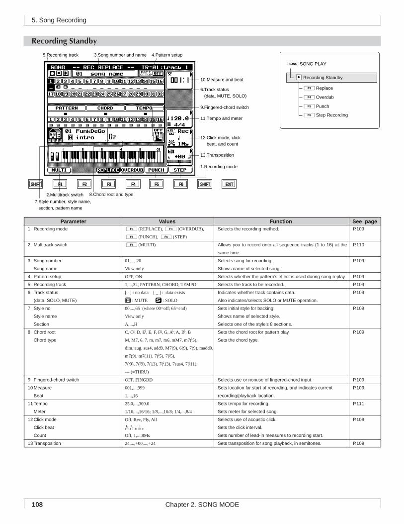
108 Chapter 2. SONG MODE
5. Song Recording
Recording Standby
3.Song number and name
7.Style number, style name, section, pattern name
SHIFT F1 F2 F3 F4 F5 F6 SHIFT EXIT
5.Recording track 4.Pattern setup
6.Track status (data, MUTE, SOLO)
11.Tempo and meter
12.Click mode, click beat, and count
13.Transposition
9.Fingered-chord switch
10.Measure and beat
1.Recording mode
2.Multitrack switch 8.Chord root and type
sSONG PLAY
3Replace
4Overdub
5Punch
6Step Recording
eRecording Standby
Selects the recording method.
Allows you to record onto all sequence tracks (1 to 16) at the
same time.
Selects song for recording.
Shows name of selected song.
Selects whether the pattern’s effect is used during song replay.
Selects the track to be recorded.
Indicates whether track contains data.
Also indicates/selects SOLO or MUTE operation.
Sets initial style for backing.
Shows name of selected style.
Selects one of the style’s 8 sections.
Sets the chord root for pattern play.
Sets the chord type.
Selects use or nonuse of fingered-chord input.
Sets location for start of recording, and indicates current
recording/playback location.
Sets tempo for recording.
Sets meter for selected song.
Selects use of acoustic click.
Sets the click interval.
Sets number of lead-in measures to recording start.
Sets transposition for song playback, in semitones.
3(REPLACE), 4(OVERDUB),
5(PUNCH), 6(STEP)
1(MULTI)
01,..., 20
View only
OFF, ON
1,...,32, PATTERN, CHORD, TEMPO
[ ] : no data [ _ ] : data exists
: MUTE : SOLO
00,...,65 (where 00=off; 65=end)
View only
A,...,H
C, C#, D, Eb, E, F, F#, G, Ab, A, Bb, BM, M7, 6, 7, m, m7, m6, mM7, m7(b5),
dim, aug, sus4, add9, M7(9), 6(9), 7(9), madd9,
m7(9), m7(11), 7(b5), 7(#5),
7(b9), 7(#9), 7(13), 7(b13), 7sus4, 7(#11),
--- (=THRU)
OFF, FINGRD
001,...,999
1,...,16
25.0,...,300.0
1/16,...,16/16; 1/8,...,16/8; 1/4,...,8/4
Off, Rec, Ply, All
x, e, q, h, úOff, 1,...,8Ms
24,...,+00,...,+24
1 Recording mode
2 Multitrack switch
3 Song number
Song name
4 Pattern setup
5 Recording track
6 Track status
(data, SOLO, MUTE)
7 Style no.
Style name
Section
8 Chord root
Chord type
9 Fingered-chord switch
10 Measure
Beat
11 Tempo
Meter
12 Click mode
Click beat
Count
13 Transposition
Parameter Values Function See pageP.109
P.110
P.109
P.109
P.109
P.109
P.109
P.109
P.109
P.109
P.111
P.109
P.109
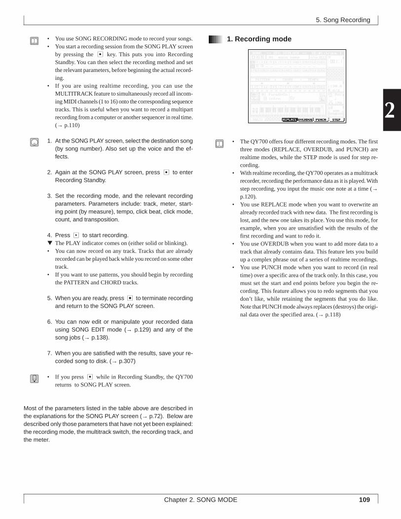
109Chapter 2. SONG MODE
2
• You use SONG RECORDING mode to record your songs.• You start a recording session from the SONG PLAY screen
by pressing the e key. This puts you into RecordingStandby. You can then select the recording method and setthe relevant parameters, before beginning the actual record-ing.
• If you are using realtime recording, you can use theMULTITRACK feature to simultaneously record all incom-ing MIDI channels (1 to 16) onto the corresponding sequencetracks. This is useful when you want to record a multipartrecording from a computer or another sequencer in real time.(→ p.110)
1. At the SONG PLAY screen, select the destination song(by song number). Also set up the voice and the ef-fects.
2. Again at the SONG PLAY screen, press e to enterRecording Standby.
3. Set the recording mode, and the relevant recordingparameters. Parameters include: track, meter, start-ing point (by measure), tempo, click beat, click mode,count, and transposition.
4. Press p to start recording.▼ The PLAY indicator comes on (either solid or blinking).• You can now record on any track. Tracks that are already
recorded can be played back while you record on some othertrack.
• If you want to use patterns, you should begin by recordingthe PATTERN and CHORD tracks.
5. When you are ready, press s to terminate recordingand return to the SONG PLAY screen.
6. You can now edit or manipulate your recorded datausing SONG EDIT mode (→ p.129) and any of thesong jobs (→ p.138).
7. When you are satisfied with the results, save your re-corded song to disk. (→ p.307)
• If you press e while in Recording Standby, the QY700returns to SONG PLAY screen.
Most of the parameters listed in the table above are described inthe explanations for the SONG PLAY screen (→ p.72). Below aredescribed only those parameters that have not yet been explained:the recording mode, the multitrack switch, the recording track, andthe meter.
1. Recording mode
• The QY700 offers four different recording modes. The firstthree modes (REPLACE, OVERDUB, and PUNCH) arerealtime modes, while the STEP mode is used for step re-cording.
• With realtime recording, the QY700 operates as a multitrackrecorder, recording the performance data as it is played. Withstep recording, you input the music one note at a time (→p.120).
• You use REPLACE mode when you want to overwrite analready recorded track with new data. The first recording islost, and the new one takes its place. You use this mode, forexample, when you are unsatisfied with the results of thefirst recording and want to redo it.
• You use OVERDUB when you want to add more data to atrack that already contains data. This feature lets you buildup a complex phrase out of a series of realtime recordings.
• You use PUNCH mode when you want to record (in realtime) over a specific area of the track only. In this case, youmust set the start and end points before you begin the re-cording. This feature allows you to redo segments that youdon’t like, while retaining the segments that you do like.Note that PUNCH mode always replaces (destroys) the origi-nal data over the specified area. (→ p.118)
5. Song Recording
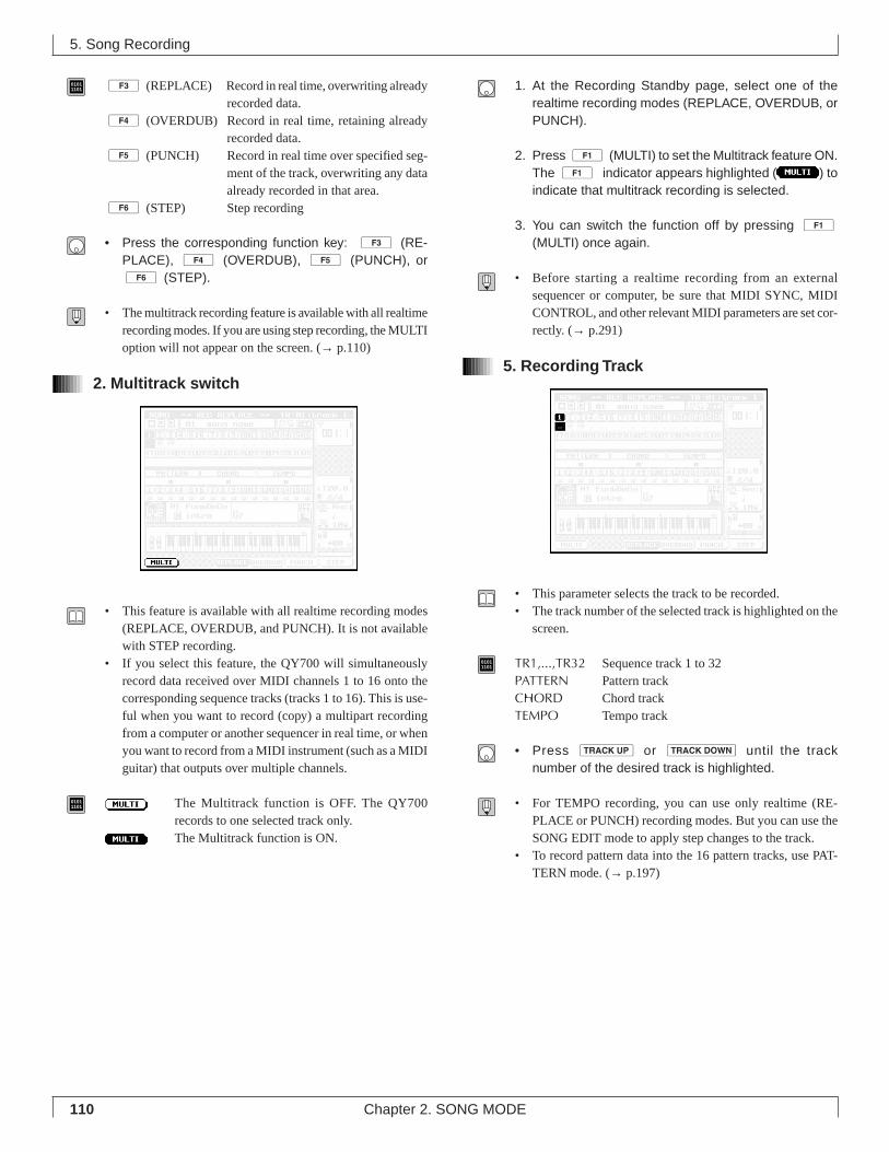
110 Chapter 2. SONG MODE
01011101 3 (REPLACE) Record in real time, overwriting already
recorded data.4 (OVERDUB) Record in real time, retaining already
recorded data.5 (PUNCH) Record in real time over specified seg-
ment of the track, overwriting any dataalready recorded in that area.
6 (STEP) Step recording
• Press the corresponding function key: 3 (RE-PLACE), 4 (OVERDUB), 5 (PUNCH), or6 (STEP).
• The multitrack recording feature is available with all realtimerecording modes. If you are using step recording, the MULTIoption will not appear on the screen. (→ p.110)
2. Multitrack switch
• This feature is available with all realtime recording modes(REPLACE, OVERDUB, and PUNCH). It is not availablewith STEP recording.
• If you select this feature, the QY700 will simultaneouslyrecord data received over MIDI channels 1 to 16 onto thecorresponding sequence tracks (tracks 1 to 16). This is use-ful when you want to record (copy) a multipart recordingfrom a computer or another sequencer in real time, or whenyou want to record from a MIDI instrument (such as a MIDIguitar) that outputs over multiple channels.
01011101 The Multitrack function is OFF. The QY700
records to one selected track only.The Multitrack function is ON.
1. At the Recording Standby page, select one of therealtime recording modes (REPLACE, OVERDUB, orPUNCH).
2. Press 1 (MULTI) to set the Multitrack feature ON.The 1 indicator appears highlighted ( ) toindicate that multitrack recording is selected.
3. You can switch the function off by pressing 1(MULTI) once again.
• Before starting a realtime recording from an externalsequencer or computer, be sure that MIDI SYNC, MIDICONTROL, and other relevant MIDI parameters are set cor-rectly. (→ p.291)
5. Recording Track
• This parameter selects the track to be recorded.• The track number of the selected track is highlighted on the
screen.
01011101 TR1,...,TR32 Sequence track 1 to 32
PATTERN Pattern trackCHORD Chord trackTEMPO Tempo track
• Press u or d until the tracknumber of the desired track is highlighted.
• For TEMPO recording, you can use only realtime (RE-PLACE or PUNCH) recording modes. But you can use theSONG EDIT mode to apply step changes to the track.
• To record pattern data into the 16 pattern tracks, use PAT-TERN mode. (→ p.197)
5. Song Recording
111Chapter 2. SONG MODE
2
11. Meter
• This parameter sets the meter for each measure of the song.The selected meter applies to all tracks.
• Although you will generally set these values before startingto record, you are also free to set or change them after re-cording is completed. If your song will include timechanges, you can record the whole song in a standard metersuch 4/4 and then make the required adjustments later.
• You can use step recording of the PATTERN track (→ p.125)to adjust each measure’s meter value.
01011101 1/16,...,16/16, 1/8,...,16/8, 1/4,...,8/4
1. Press d [D3] to move the cursor to the meter set-ting area.
2. Set the value using the data dial or the n or y key.
• To change the meter at some internal point within the song:First select the measure at which you want to make thechange, and then set the meter value.
5. Song Recording

112 Chapter 2. SONG MODE
5. Song Recording
Realtime Recording: Sequence Tracks (TR1,...,TR32)
6. When you are ready to stop recording, press s.▼ The QY700 returns to the SONG PLAY screen.
• You can use song job 00 (UNDO/REDO) to cancel a re-cording that you have just made. This allows you to recoverdata that you have inadvertently over-recorded. (→ p.141)
• Remember to set the appropriate parameters (such as meas-ure, tempo, meter, click beat, click mode, count, and trans-position) before beginning the recording. (→ p.109)
• If you have selected a style number and section, the QY700will start pattern replay at the same time that it starts torecord. If you don’t want to hear a pattern, set the stylenumber to 00.
• If you have selected a pattern whose section connection isset to End, the QY700 will automatically stop recordingwhen the pattern playback reaches its end. If you do notwant this to happen, select a different pattern or else changethe section connection setting. (→ p.202)
• You can use the 1 (MULTI) function to make a si-multaneous recording of multiple MIDI channels.(→ p.110)
• Sequence tracks can record system-exclusive data, subjectto memory constraints. (You can use your QY700 as a MIDIdata filer.)
• If you input your recording using the QY700 keyboard keys,the velocity for each note is set to 88( f ). If you want truerecording of velocity values, use a remote MIDI keyboardfor the input.
• Before recording onto the QY700 from a remote keyboard,go to UTILITY mode and set the MIDI “echoback” settingto “RecMonitor”. (→ p.292)
• You use this function to record a performance in real time.You can input the performance using the QY700microkeyboard, a remote MIDI keyboard, or some othertype of remote MIDI device
• This section describes the 3 (REPLACE ) and 4(OVERDUB) realtime recording methods. The 5
(PUNCH) method, which is also realtime, is described on alater page.
• You use the 3 (REPLACE) method when you want tooverwrite any data already existing on the track – for exam-ple, when you want to redo a phrase that you are not satis-fied with.
• You use 4 (OVERDUB) when you want to add yournew performance data to the data already contained in thetrack. This allows you to build up a complex phrase by re-cording it as a combination of several parts.
1. At the SONG PLAY screen, press e.▼ The QY700 displays the Recording Standby page. The RE-
CORDING indicator comes on.
2. Press 3 (REPLACE) or 4 (OVERDUB) toselect the recording method.
3. Press u or d as necessary toselect the track you want to record.
4. Press p.▼ The PLAY indicator begins flashing. The QY700 counts
out the specified number of lead-in measures (as set by theCOUNT parameter; see page 78), and then begins the re-cording.
5. Input the performance data from the microkeyboardor your remote MIDI instrument.
SHIFT F1 F2 F3 F4 F5 F6 SHIFT EXIT
Recording track
Recording mode
sSONG PLAY
3Replace
4Overdub
eSong recording
TR1~TR32
PATTERN
CHORD
TEMPO
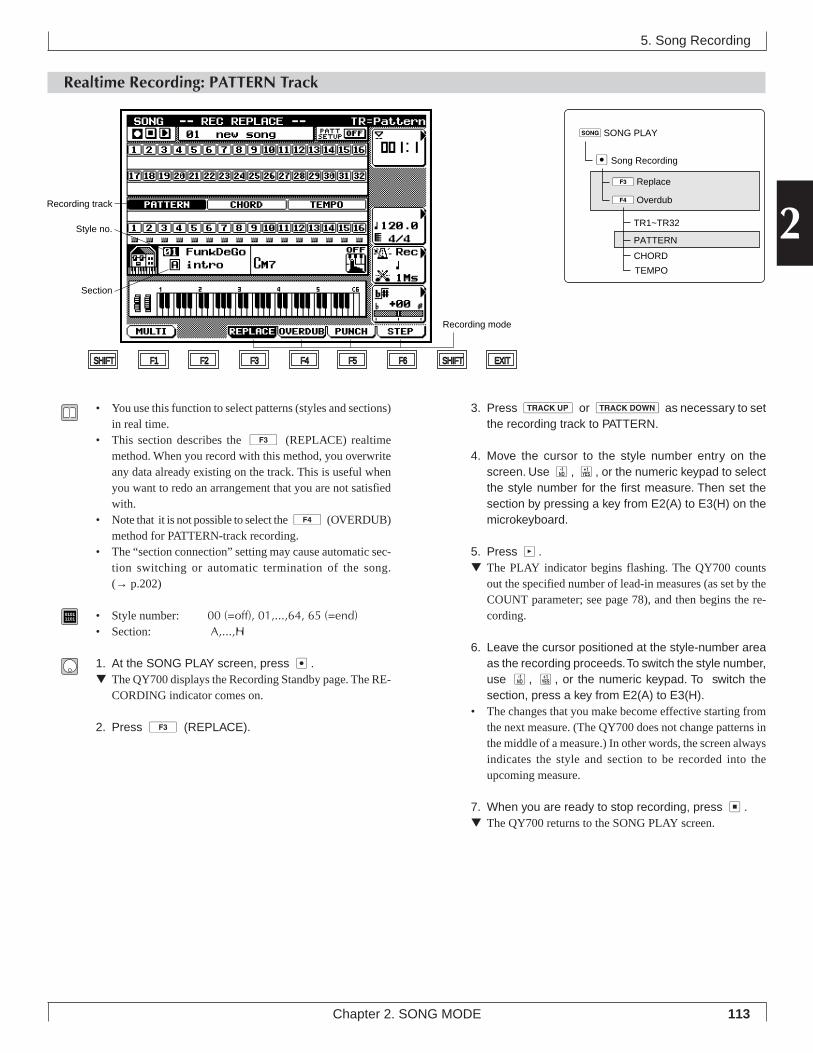
113Chapter 2. SONG MODE
2
5. Song Recording
Realtime Recording: PATTERN Track
3. Press u or d as necessary to setthe recording track to PATTERN.
4. Move the cursor to the style number entry on thescreen. Use n, y, or the numeric keypad to selectthe style number for the first measure. Then set thesection by pressing a key from E2(A) to E3(H) on themicrokeyboard.
5. Press p.▼ The PLAY indicator begins flashing. The QY700 counts
out the specified number of lead-in measures (as set by theCOUNT parameter; see page 78), and then begins the re-cording.
6. Leave the cursor positioned at the style-number areaas the recording proceeds. To switch the style number,use n, y, or the numeric keypad. To switch thesection, press a key from E2(A) to E3(H).
• The changes that you make become effective starting fromthe next measure. (The QY700 does not change patterns inthe middle of a measure.) In other words, the screen alwaysindicates the style and section to be recorded into theupcoming measure.
7. When you are ready to stop recording, press s.▼ The QY700 returns to the SONG PLAY screen.
• You use this function to select patterns (styles and sections)in real time.
• This section describes the 3 (REPLACE) realtimemethod. When you record with this method, you overwriteany data already existing on the track. This is useful whenyou want to redo an arrangement that you are not satisfiedwith.
• Note that it is not possible to select the 4 (OVERDUB)method for PATTERN-track recording.
• The “section connection” setting may cause automatic sec-tion switching or automatic termination of the song.(→ p.202)
01011101 • Style number: 00 (=off), 01,...,64, 65 (=end)
• Section: A,...,H
1. At the SONG PLAY screen, press e.▼ The QY700 displays the Recording Standby page. The RE-
CORDING indicator comes on.
2. Press 3 (REPLACE).
SHIFT F1 F2 F3 F4 F5 F6 SHIFT EXIT
Recording track
Recording mode
Style no.
Section
sSONG PLAY
3Replace
4Overdub
eSong Recording
TR1~TR32
PATTERN
CHORD
TEMPO
114 Chapter 2. SONG MODE
• You can use song job 00 (UNDO/REDO) to cancel a re-cording that you have just made. This allows you to recoverdata that you have inadvertently over-recorded. (→ p.141)
• Remember to set the appropriate parameters (such as meas-ure, tempo, meter, click beat, click mode, count, and trans-position) before beginning the recording. (→ p.109)
• It is a good idea to select a slow tempo. This will make iteasier to enter the style and section values at the right time.
• Set the style number at the end of the song to 65 (=end). Ifyou set a different value, the song will not end. (→ p.113)
• You can use step recording of the PATTERN track to re-view or modify the recorded style and section values.(→ p.125)
5. Song Recording
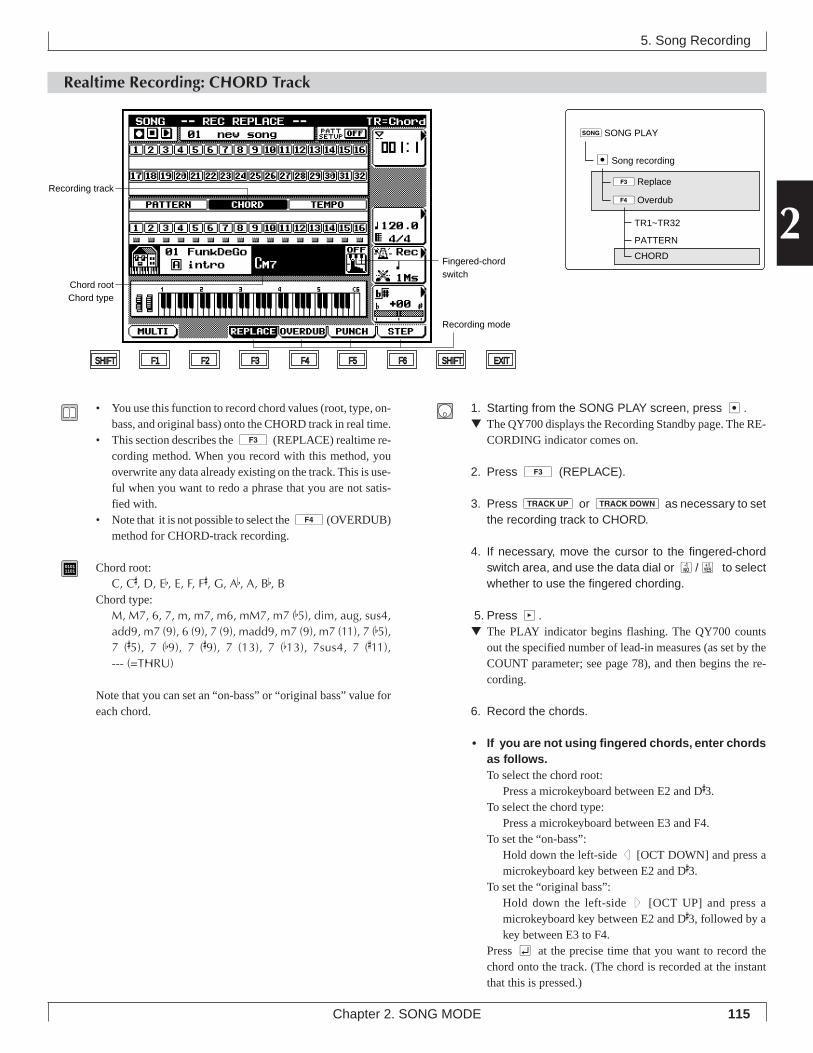
115Chapter 2. SONG MODE
2
5. Song Recording
Realtime Recording: CHORD Track
1. Starting from the SONG PLAY screen, press e.▼ The QY700 displays the Recording Standby page. The RE-
CORDING indicator comes on.
2. Press 3 (REPLACE).
3. Press u or d as necessary to setthe recording track to CHORD.
4. If necessary, move the cursor to the fingered-chordswitch area, and use the data dial or n/y to selectwhether to use the fingered chording.
5. Press p.▼ The PLAY indicator begins flashing. The QY700 counts
out the specified number of lead-in measures (as set by theCOUNT parameter; see page 78), and then begins the re-cording.
6. Record the chords.
• If you are not using fingered chords, enter chordsas follows.To select the chord root:
Press a microkeyboard between E2 and D#3.To select the chord type:
Press a microkeyboard between E3 and F4.To set the “on-bass”:
Hold down the left-side d [OCT DOWN] and press amicrokeyboard key between E2 and D#3.
To set the “original bass”:Hold down the left-side u [OCT UP] and press amicrokeyboard key between E2 and D#3, followed by akey between E3 to F4.
Press e at the precise time that you want to record thechord onto the track. (The chord is recorded at the instantthat this is pressed.)
• You use this function to record chord values (root, type, on-bass, and original bass) onto the CHORD track in real time.
• This section describes the 3 (REPLACE) realtime re-cording method. When you record with this method, youoverwrite any data already existing on the track. This is use-ful when you want to redo a phrase that you are not satis-fied with.
• Note that it is not possible to select the 4(OVERDUB)method for CHORD-track recording.
01011101 Chord root:
C, C#, D, Eb, E, F, F#, G, Ab, A, Bb, BChord type:
M, M7, 6, 7, m, m7, m6, mM7, m7 (b5), dim, aug, sus4,add9, m7 (9), 6 (9), 7 (9), madd9, m7 (9), m7 (11), 7 (b5),7 (#5), 7 (b9), 7 (#9), 7 (13), 7 (b13), 7sus4, 7 (#11),--- (=THRU)
Note that you can set an “on-bass” or “original bass” value foreach chord.
SHIFT F1 F2 F3 F4 F5 F6 SHIFT EXIT
Recording track
Recording mode
Chord rootChord type
Fingered-chord switch
sSONG PLAY
3Replace
4Overdub
eSong recording
TR1~TR32
PATTERN
CHORD
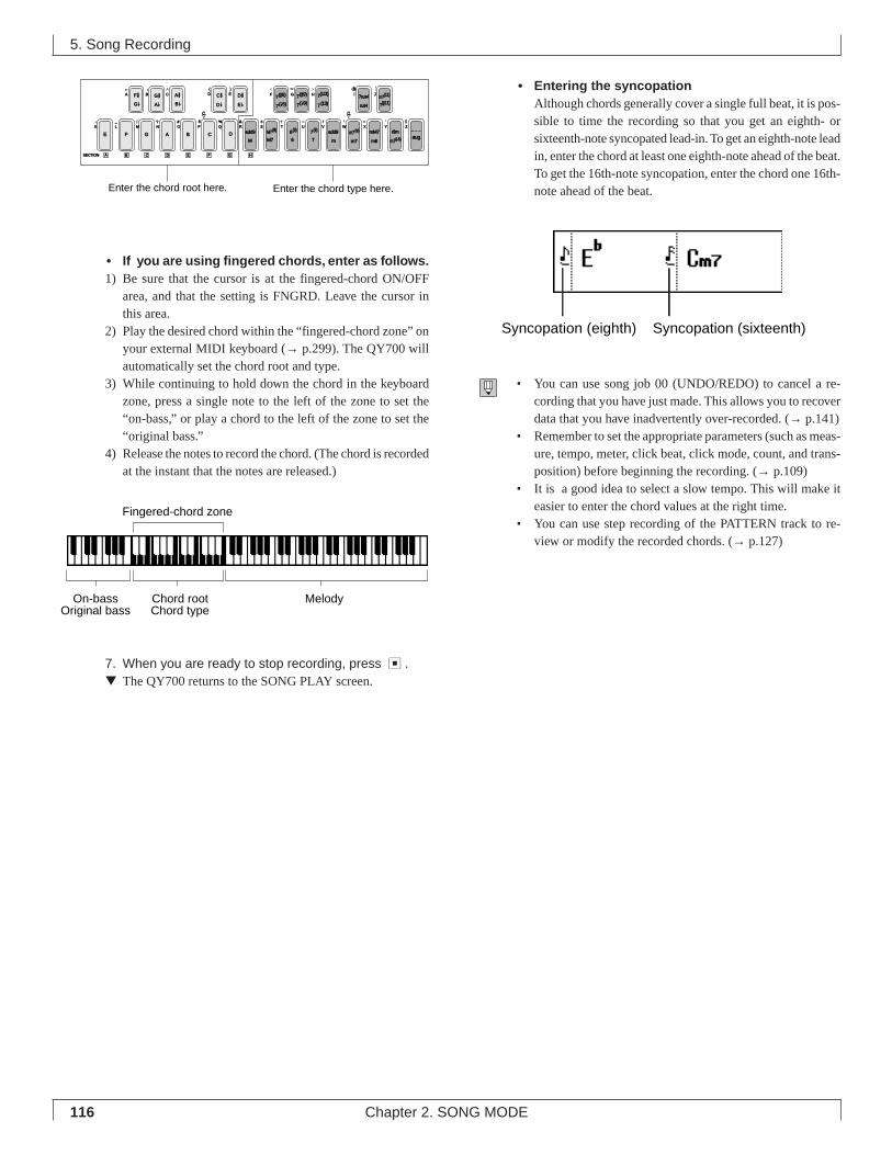
116 Chapter 2. SONG MODE
• If you are using fingered chords, enter as follows.1) Be sure that the cursor is at the fingered-chord ON/OFF
area, and that the setting is FNGRD. Leave the cursor inthis area.
2) Play the desired chord within the “fingered-chord zone” onyour external MIDI keyboard (→ p.299). The QY700 willautomatically set the chord root and type.
3) While continuing to hold down the chord in the keyboardzone, press a single note to the left of the zone to set the“on-bass,” or play a chord to the left of the zone to set the“original bass.”
4) Release the notes to record the chord. (The chord is recordedat the instant that the notes are released.)
7. When you are ready to stop recording, press s.▼ The QY700 returns to the SONG PLAY screen.
• Entering the syncopationAlthough chords generally cover a single full beat, it is pos-sible to time the recording so that you get an eighth- orsixteenth-note syncopated lead-in. To get an eighth-note leadin, enter the chord at least one eighth-note ahead of the beat.To get the 16th-note syncopation, enter the chord one 16th-note ahead of the beat.
• You can use song job 00 (UNDO/REDO) to cancel a re-cording that you have just made. This allows you to recoverdata that you have inadvertently over-recorded. (→ p.141)
• Remember to set the appropriate parameters (such as meas-ure, tempo, meter, click beat, click mode, count, and trans-position) before beginning the recording. (→ p.109)
• It is a good idea to select a slow tempo. This will make iteasier to enter the chord values at the right time.
• You can use step recording of the PATTERN track to re-view or modify the recorded chords. (→ p.127)
5. Song Recording
F #
E F G A B C DM
add9
M7
add9
a
m
mM7
m6
c
C # D #7(#5)
7( b5)
7(#9) 7sus4
sus4
SECTION A
G b D b E b 7( b9)
m7(b5)
M7(9)
6
6(9)
7
7(9) m7(9)
m7
dimZWV
/
HGF
UTSRQPO#
N
CBA
?MLK
_ ! S % &
E)
D(
_
YX
aug
7( b13)
7(13) 7(#11)
JI m7(11)
c
G #A b
A #B b
B C D E F G H
Enter the chord type here.Enter the chord root here.
On-bassOriginal bass
Chord rootChord type
Melody
Fingered-chord zone
Syncopation (eighth) Syncopation (sixteenth)
117Chapter 2. SONG MODE
2
Realtime Recording: TEMPO Track
5. Song Recording
SHIFT F1 F2 F3 F4 F5 F6 SHIFT EXIT
Recording track
Recording mode
5. Make the required tempo changes using the data dial,n/y, or the numeric keypad.
▼ The tempo changes are recorded as you make them.
6. When you are finished recording the tempo changes,press s.
▼ The QY700 returns to the SONG PLAY screen.
• You use this function to record tempo changes for the song.• This section describes the 3 (REPLACE ) realtime
recording method. When you record with this method, youoverwrite any data already existing on the track.
• Note that it is not possible to select the 4 (OVERDUB)method for TEMPO-track recording.
01011101 Tempo: q = 25.0,...,300.0
1. Starting from the SONG PLAY page, press e.▼ The QY700 displays the Recording Standby page. The RE-
CORDING indicator comes on.
2. Press 3 (REPLACE).
3. Press u or d as necessary to setthe recording track to TEMPO.
4. Press p.▼ The PLAY indicator begins flashing. The QY700 counts
out the specified number of lead-in measures (as set by theCOUNT parameter; see page 78), and then begins the re-cording. The cursor automatically moves to the tempo en-try area.
sSONG PLAY
3Replace
4Overdub
eSong Recording
TR1~TR32
PATTERN
CHORD
TEMPO
118 Chapter 2. SONG MODE
Punch Recording
5. Song Recording
5. Press d [D1] to move the cursor to the song-measure entry area. Set the measure at which youwant playback to begin.
• You will generally want to start playback several measuresbefore the punch-in point.
6. Press p.▼ The PLAY indicator begins flashing, and song playback be-
gins from the measure you specified at Step 5 above. TheQY700 then automatically switches into recording opera-tion when the song reaches the punch-in point. It thenresumes playback upon reaching the punch-out point.
7. Input the data you wish to record, in real time. Whenyou are finished, press s to return to the SONG PLAYscreen.
Punch-In Point
• This is the point within the song at which the QY700 be-gins realtime recording operation. You set this point by speci-fying its measure and beat.
Punch-Out Point
• This is the point within the song at which recording stops,and the QY700 resumes song playback. You set this pointby measure and beat.
• With punch recording, you record over (replace) a specificarea in an already recorded track. You begin by setting upthe start and end points (the punch-in and punch-out points)for the area you want to replace. You then record over thearea in real time.
• You set the punch-in and punch-out points by specifyingthe measure and beat.
• With the exception of the punch-in and punch-out settings,this method is identical to the REPLACE method forrealtime recording. For additional information, see page 112.
1. Starting from the SONG PLAY screen, press e.▼ The QY700 displays the Recording Standby page. The RE-
CORDING indicator comes on.
2. Press 5 (PUNCH).
3. Press u or d as necessary toselect the track you want to record. You can select anyof the sequence tracks (TR1,...,TR32) or the PATTERN,CHORD, or TEMPO track.
4. Press d [D2] to position the cursor in the punch-point entry area. Set the punch-in and punch-out val-ues (both measure and beat) using the data dial, n/y, or the numeric keypad.
SHIFT F1 F2 F3 F4 F5 F6 SHIFT EXIT
Recordingtrack
Recording mode
Punch-in pointPunch-out point
Song measure
sSONG PLAY
5PUNCH
eSong Recording
TR1~TR32
PATTERN
CHORD
TEMPO
119Chapter 2. SONG MODE
2
• The figure below illustrates the process. The QY700switches from PLAY to RECORD at the punch-in point,then returns to PLAY at the punch-out point.
5. Song Recording
If settings are: → 013: 1 ← 016: 1Then:
Punch-in point
Operation switches fromplayback to recording at
Measure 13, Beat 1 of the song.
Punch-out point
Recording stops and playback resumes at Measure 16, Beat 1.
RecordPlay Play
120 Chapter 2. SONG MODE
Step Recording: Sequence Tracks (TR1,...,TR32)
5. Song Recording
8. If you make an incorrect entry, you can delete it asfollows.• To delete the last note you entered, press 5
(BkDelete). The location pointer moves back to posi-tion it had just before you entered the note.
• To delete some other note: Move the location pointer tothe note’s location and press 6 (Delete). All notesthat start at that position will be deleted.
9. When you have finished making your entries, presss to terminate the recording and return to the SONGPLAY screen.
• Under step recording, note registration occurs when yourelease the key(s), rather than when you press them. Thismakes it easy to enter a block chord: you can pick out thenotes one by one and then release them all at the same time.
• You may want to enter rough velocity values at this point(using only f, p, and mp, for example). You can then use oneof the song jobs (such as Crescendo or Modify Velocity) toadjust the values later. (→ p.138)
• Step recording supports entry of note data only. You canadd other types of data using the SONG EDIT mode’s In-sert function (→ p.133).
The remainder of this section describes the step recording param-eters (the parameters displayed on the screen) and the use of them and s keys,.
• You use this method to create a recording one note at a time,setting appropriate values for each note’s length, velocity,and so on.
1. Starting from the SONG PLAY screen, press e.▼ The QY700 displays the Recording Standby page. The RE-
CORDING indicator comes on.
2. Press 6 (STEP) to select step recording.
3. Press u or d as necessary to se-lect the sequence track you want to record on(TR1,...,TR32).
4. Press p.▼ The PLAY indicator comes on. The QY700 displays the
step recording page for sequence-track recording.
5. Move the location pointer to the point where you wantto enter a note, using n/y, the data dial, or theshuttle dial.
• To jump to a distant measure: Press d [D1] to movethe cursor to the location-setting area, then enter the meas-ure number with the numeric keypad.
6. Set the step time, velocity, and gate time. To set eachvalue, press the corresponding key (d [D2] forstep time, d [D3] for velocity, d [D4] for gatetime) to move the cursor to the entry area, then enterthe value using the data dial, n/y, or numerickeypad.
7. Now enter the note itself. You can select the note us-ing either the microkeyboard or an external MIDI key-board. If you want to enter a rest, press the mkey. If you want to enter a tie, press the s key.
Back delete
SHIFT F1 F2 F3 F4 F5 F6 SHIFT EXIT
Piano roll
Gate time
Velocity
Step time
Location pointerBeat graph
Location
sSONG PLAY
6Step Recording
eSong Recording
TR1~TR32
PATTERN
CHORD
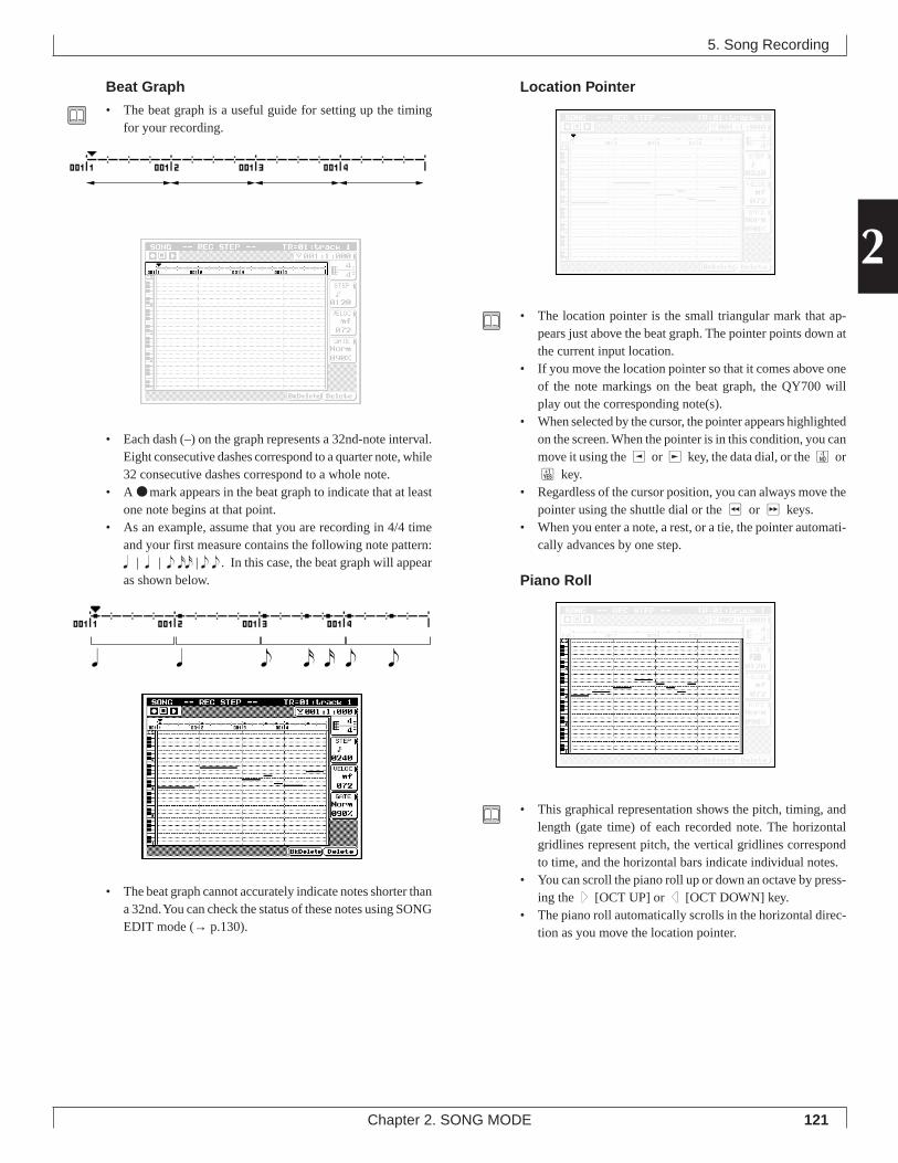
121Chapter 2. SONG MODE
2
Beat Graph
• The beat graph is a useful guide for setting up the timingfor your recording.
• Each dash (–) on the graph represents a 32nd-note interval.Eight consecutive dashes correspond to a quarter note, while32 consecutive dashes correspond to a whole note.
• A ● mark appears in the beat graph to indicate that at leastone note begins at that point.
• As an example, assume that you are recording in 4/4 timeand your first measure contains the following note pattern:q | q | e xx | e e . In this case, the beat graph will appearas shown below.
• The beat graph cannot accurately indicate notes shorter thana 32nd. You can check the status of these notes using SONGEDIT mode (→ p.130).
Location Pointer
• The location pointer is the small triangular mark that ap-pears just above the beat graph. The pointer points down atthe current input location.
• If you move the location pointer so that it comes above oneof the note markings on the beat graph, the QY700 willplay out the corresponding note(s).
• When selected by the cursor, the pointer appears highlightedon the screen. When the pointer is in this condition, you canmove it using the l or r key, the data dial, or the n ory key.
• Regardless of the cursor position, you can always move thepointer using the shuttle dial or the r or f keys.
• When you enter a note, a rest, or a tie, the pointer automati-cally advances by one step.
Piano Roll
• This graphical representation shows the pitch, timing, andlength (gate time) of each recorded note. The horizontalgridlines represent pitch, the vertical gridlines correspondto time, and the horizontal bars indicate individual notes.
• You can scroll the piano roll up or down an octave by press-ing the u [OCT UP] or d [OCT DOWN] key.
• The piano roll automatically scrolls in the horizontal direc-tion as you move the location pointer.
5. Song Recording
eq q ex x e
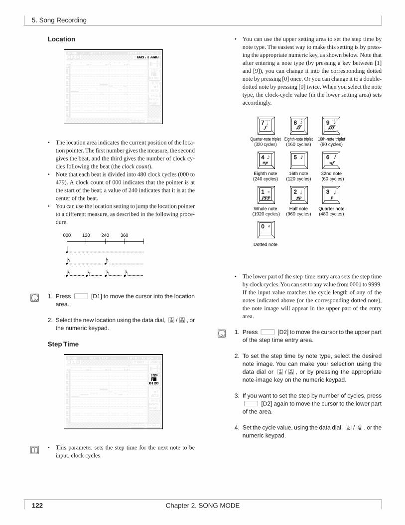
122 Chapter 2. SONG MODE
Location
• The location area indicates the current position of the loca-tion pointer. The first number gives the measure, the secondgives the beat, and the third gives the number of clock cy-cles following the beat (the clock count).
• Note that each beat is divided into 480 clock cycles (000 to479). A clock count of 000 indicates that the pointer is atthe start of the beat; a value of 240 indicates that it is at thecenter of the beat.
• You can use the location setting to jump the location pointerto a different measure, as described in the following proce-dure.
1. Press d [D1] to move the cursor into the locationarea.
2. Select the new location using the data dial, n/y, orthe numeric keypad.
Step Time
• This parameter sets the step time for the next note to beinput, clock cycles.
• You can use the upper setting area to set the step time bynote type. The easiest way to make this setting is by press-ing the appropriate numeric key, as shown below. Note thatafter entering a note type (by pressing a key between [1]and [9]), you can change it into the corresponding dottednote by pressing [0] once. Or you can change it to a double-dotted note by pressing [0] twice. When you select the notetype, the clock-cycle value (in the lower setting area) setsaccordingly.
• The lower part of the step-time entry area sets the step timeby clock cycles. You can set to any value from 0001 to 9999.If the input value matches the cycle length of any of thenotes indicated above (or the corresponding dotted note),the note image will appear in the upper part of the entryarea.
1. Press d [D2] to move the cursor to the upper partof the step time entry area.
2. To set the step time by note type, select the desirednote image. You can make your selection using thedata dial or n/y, or by pressing the appropriatenote-image key on the numeric keypad.
3. If you want to set the step by number of cycles, pressd [D2] again to move the cursor to the lower partof the area.
4. Set the cycle value, using the data dial, n/y, or thenumeric keypad.
5. Song Recording
000 120 360240
7 8 9
4 5 6
1 2 3
0
Quarter-note triplet(320 cycles)
Eighth-note triplet(160 cycles)
16th-note triplet(80 cycles)
Eighth note(240 cycles)
16th note(120 cycles)
32nd note (60 cycles)
Whole note (1920 cycles)
Half note(960 cycles)
Quarter note(480 cycles)
Dotted note

123Chapter 2. SONG MODE
2
Velocity
• This velocity entry area sets the velocity (force) for the nextnote to be input.
• The upper part of the entry area sets the velocity by its mu-sical notation. Again, the easiest way to make the setting isby pressing one of the numeric keys. When you select thenotation, the corresponding velocity value (see illustrationbelow) automatically appears in the lower setting area.
• You can use the lower entry area to set an actual MIDI ve-locity value (from 001 to 127). When you enter a value, acorresponding notation will appear in the upper entry area.(If you set the value to 0 (EXT), the QY700 sets the veloci-ties according to the keyboard input.)
1. Press d [D3] to move the cursor to the upper partof the velocity entry area.
2. To set the value by notation, select the notation (suchas ff or mp) using the data dial or n/y, or by press-ing the appropriate numeric key.
3. If you want to set a numerical velocity value, pressd [D3] again to move the cursor to the lower partof the area.
4. Set the value using the data dial, n/y, or the nu-meric keypad.
Gate Time
• This value sets the note length (time that the note is actuallysounded), as a percentage of the step time. For example,you can set the note to play staccato, so that its soundswitches off well before its step time is over. Or you canhold it right up to the start of the next step (so that it slursinto the next note).
• You can use the upper part of the entry area to set the gatetime by type. (When you make your selection, the corre-sponding percentage value will appear in the lower part ofthe entry area.) Three types are available, as follows.
Stac (staccato) The gate time is 50% of the step time.Norm (normal) The gate time is 90% of the step time.Slur The gate time is 99% of the step time.
• You can use the lower part of the setting area to set the gatetime as an explicit percentage (from 001% to 120%) of thegate time.
1. Press d [D4] to move the cursor to the upper partof the gate-time entry area.
2. To set the step time by type, select the appropriatetype value (Step, Norm, or Slur) using the data dial orthe n or y key.
5. Song Recording
Step time
Gate time
Stac
Norm
Slur
240=480×50%
480 clock cycles
432=480×90%
475=480×99%
7 8 9
4 5 6
1 2 3
0
f : (088) ff : (104) fff : (120)
mp : (056) (064) mf: (072)
ppp : (008) pp : (024) p : (040)
EXT (Keyboard velocity)
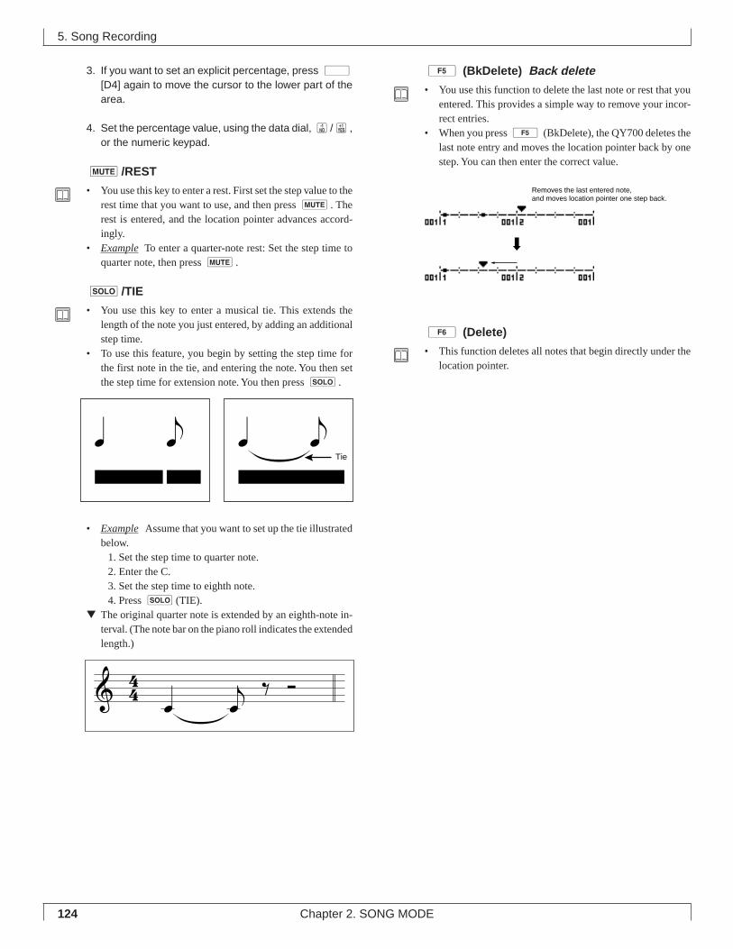
124 Chapter 2. SONG MODE
3. If you want to set an explicit percentage, press d[D4] again to move the cursor to the lower part of thearea.
4. Set the percentage value, using the data dial, n/y,or the numeric keypad.
m/REST
• You use this key to enter a rest. First set the step value to therest time that you want to use, and then press m. Therest is entered, and the location pointer advances accord-ingly.
• Example To enter a quarter-note rest: Set the step time toquarter note, then press m.
s/TIE
• You use this key to enter a musical tie. This extends thelength of the note you just entered, by adding an additionalstep time.
• To use this feature, you begin by setting the step time forthe first note in the tie, and entering the note. You then setthe step time for extension note. You then press s.
• Example Assume that you want to set up the tie illustratedbelow.
1. Set the step time to quarter note.2. Enter the C.3. Set the step time to eighth note.4. Press s (TIE).
▼ The original quarter note is extended by an eighth-note in-terval. (The note bar on the piano roll indicates the extendedlength.)
5 (BkDelete) Back delete
• You use this function to delete the last note or rest that youentered. This provides a simple way to remove your incor-rect entries.
• When you press 5 (BkDelete), the QY700 deletes thelast note entry and moves the location pointer back by onestep. You can then enter the correct value.
6 (Delete)
• This function deletes all notes that begin directly under thelocation pointer.
5. Song Recording
Removes the last entered note, and moves location pointer one step back.
Tie
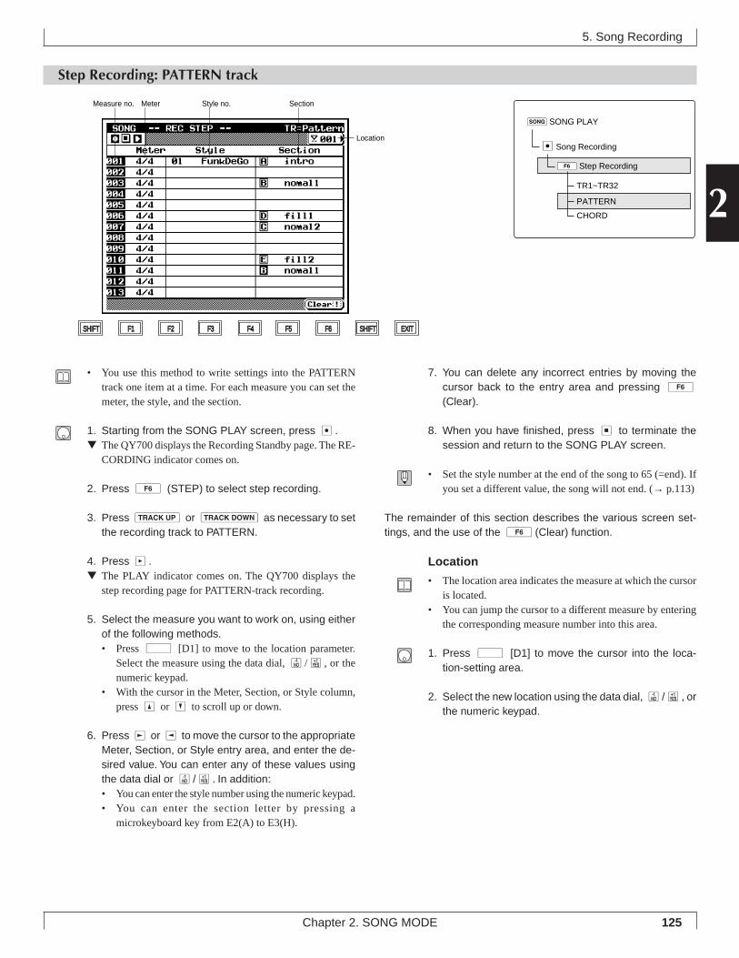
125Chapter 2. SONG MODE
2
5. Song Recording
Step Recording: PATTERN track
7. You can delete any incorrect entries by moving thecursor back to the entry area and pressing 6(Clear).
8. When you have finished, press s to terminate thesession and return to the SONG PLAY screen.
• Set the style number at the end of the song to 65 (=end). Ifyou set a different value, the song will not end. (→ p.113)
The remainder of this section describes the various screen set-tings, and the use of the 6 (Clear) function.
Location
• The location area indicates the measure at which the cursoris located.
• You can jump the cursor to a different measure by enteringthe corresponding measure number into this area.
1. Press d [D1] to move the cursor into the loca-tion-setting area.
2. Select the new location using the data dial, n/y, orthe numeric keypad.
• You use this method to write settings into the PATTERNtrack one item at a time. For each measure you can set themeter, the style, and the section.
1. Starting from the SONG PLAY screen, press e.▼ The QY700 displays the Recording Standby page. The RE-
CORDING indicator comes on.
2. Press 6 (STEP) to select step recording.
3. Press u or d as necessary to setthe recording track to PATTERN.
4. Press p.▼ The PLAY indicator comes on. The QY700 displays the
step recording page for PATTERN-track recording.
5. Select the measure you want to work on, using eitherof the following methods.• Press d [D1] to move to the location parameter.
Select the measure using the data dial, n/y, or thenumeric keypad.
• With the cursor in the Meter, Section, or Style column,press u or d to scroll up or down.
6. Press r or l to move the cursor to the appropriateMeter, Section, or Style entry area, and enter the de-sired value. You can enter any of these values usingthe data dial or n/y. In addition:• You can enter the style number using the numeric keypad.• You can enter the section letter by pressing a
microkeyboard key from E2(A) to E3(H).
Location
SHIFT F1 F2 F3 F4 F5 F6 SHIFT EXIT
Style no. SectionMeterMeasure no.
sSONG PLAY
6Step Recording
eSong Recording
TR1~TR32
PATTERN
CHORD
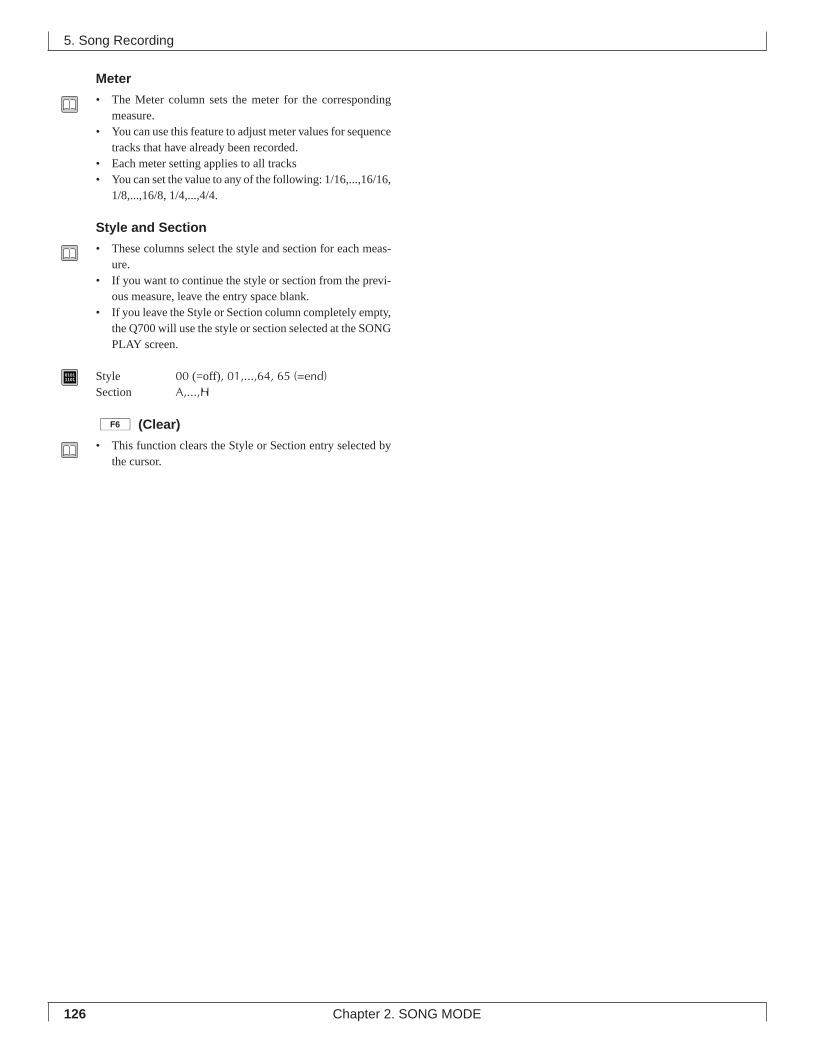
126 Chapter 2. SONG MODE
Meter
• The Meter column sets the meter for the correspondingmeasure.
• You can use this feature to adjust meter values for sequencetracks that have already been recorded.
• Each meter setting applies to all tracks• You can set the value to any of the following: 1/16,...,16/16,
1/8,...,16/8, 1/4,...,4/4.
Style and Section
• These columns select the style and section for each meas-ure.
• If you want to continue the style or section from the previ-ous measure, leave the entry space blank.
• If you leave the Style or Section column completely empty,the Q700 will use the style or section selected at the SONGPLAY screen.
01011101 Style 00 (=off), 01,...,64, 65 (=end)
Section A,...,H
6 (Clear)
• This function clears the Style or Section entry selected bythe cursor.
5. Song Recording
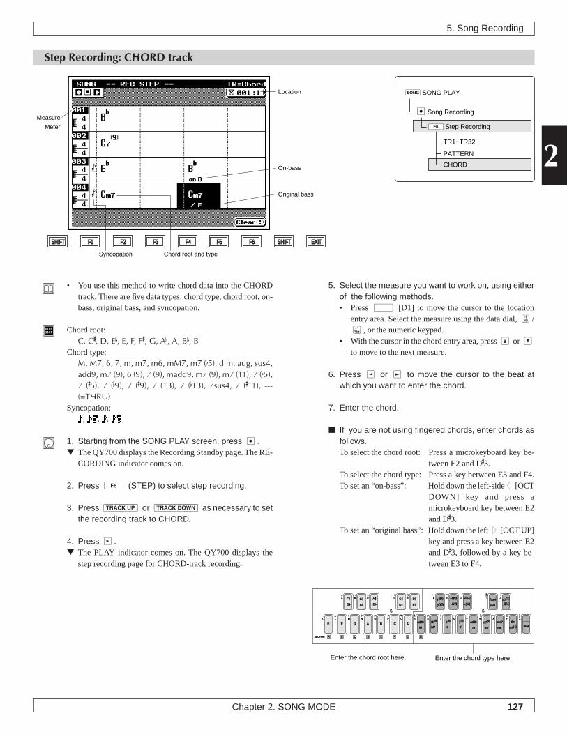
127Chapter 2. SONG MODE
2
Syncopation
SHIFT F1 F2 F3 F4 F5 F6 SHIFT EXIT
Location
On-bass
Original bass
Chord root and type
Measure
Meter
5. Song Recording
Step Recording: CHORD track
5. Select the measure you want to work on, using eitherof the following methods.• Press d [D1] to move the cursor to the location
entry area. Select the measure using the data dial, n/y, or the numeric keypad.
• With the cursor in the chord entry area, press u or dto move to the next measure.
6. Press l or r to move the cursor to the beat atwhich you want to enter the chord.
7. Enter the chord.
■ If you are not using fingered chords, enter chords asfollows.To select the chord root: Press a microkeyboard key be-
tween E2 and D#3.
To select the chord type: Press a key between E3 and F4.To set an “on-bass”: Hold down the left-sided [OCT
DOWN] key and press amicrokeyboard key between E2and D
#3.
To set an “original bass”: Hold down the left u [OCT UP]key and press a key between E2and D
#3, followed by a key be-
tween E3 to F4.
• You use this method to write chord data into the CHORDtrack. There are five data types: chord type, chord root, on-bass, original bass, and syncopation.
01011101 Chord root:
C, C#, D, Eb, E, F, F#, G, Ab, A, Bb, BChord type:
M, M7, 6, 7, m, m7, m6, mM7, m7 (b5), dim, aug, sus4,add9, m7 (9), 6 (9), 7 (9), madd9, m7 (9), m7 (11), 7 (b5),7 (#5), 7 (b9), 7 (#9), 7 (13), 7 (b13), 7sus4, 7 (#11), ---(=THRU)
Syncopation:, , ,
1. Starting from the SONG PLAY screen, press e.▼ The QY700 displays the Recording Standby page. The RE-
CORDING indicator comes on.
2. Press 6 (STEP) to select step recording.
3. Press u or d as necessary to setthe recording track to CHORD.
4. Press p.▼ The PLAY indicator comes on. The QY700 displays the
step recording page for CHORD-track recording.
F #
E F G A B C DM
add9
M7
add9
a
m
mM7
m6
c
C # D #7(#5)
7( b5)
7(#9) 7sus4
sus4
SECTION A
G b D b E b 7( b9)
m7(b5)
M7(9)
6
6(9)
7
7(9) m7(9)
m7
dimZWV
/
HGF
UTSRQPO#
N
CBA
?MLK
_ ! S % &
E)
D(
_
YX
aug
7( b13)
7(13) 7(#11)
JI m7(11)
c
G #A b
A #B b
B C D E F G H
Enter the chord type here.Enter the chord root here.
sSONG PLAY
6Step Recording
eSong Recording
TR1~TR32
PATTERN
CHORD
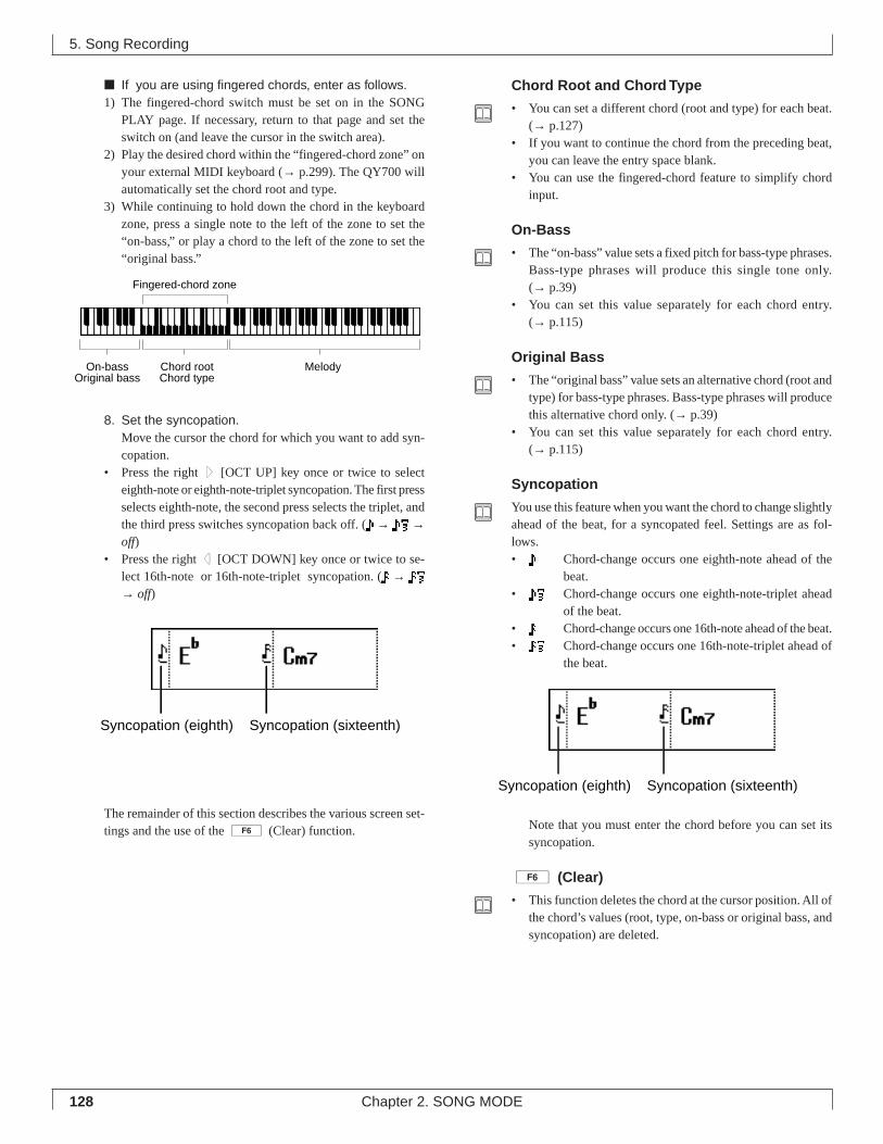
128 Chapter 2. SONG MODE
■ If you are using fingered chords, enter as follows.1) The fingered-chord switch must be set on in the SONG
PLAY page. If necessary, return to that page and set theswitch on (and leave the cursor in the switch area).
2) Play the desired chord within the “fingered-chord zone” onyour external MIDI keyboard (→ p.299). The QY700 willautomatically set the chord root and type.
3) While continuing to hold down the chord in the keyboardzone, press a single note to the left of the zone to set the“on-bass,” or play a chord to the left of the zone to set the“original bass.”
8. Set the syncopation.Move the cursor the chord for which you want to add syn-copation.
• Press the right u [OCT UP] key once or twice to selecteighth-note or eighth-note-triplet syncopation. The first pressselects eighth-note, the second press selects the triplet, andthe third press switches syncopation back off. ( → →off)
• Press the right d [OCT DOWN] key once or twice to se-lect 16th-note or 16th-note-triplet syncopation. ( → → off)
The remainder of this section describes the various screen set-tings and the use of the 6 (Clear) function.
Chord Root and Chord Type
• You can set a different chord (root and type) for each beat.(→ p.127)
• If you want to continue the chord from the preceding beat,you can leave the entry space blank.
• You can use the fingered-chord feature to simplify chordinput.
On-Bass
• The “on-bass” value sets a fixed pitch for bass-type phrases.Bass-type phrases will produce this single tone only.(→ p.39)
• You can set this value separately for each chord entry.(→ p.115)
Original Bass
• The “original bass” value sets an alternative chord (root andtype) for bass-type phrases. Bass-type phrases will producethis alternative chord only. (→ p.39)
• You can set this value separately for each chord entry.(→ p.115)
Syncopation
You use this feature when you want the chord to change slightlyahead of the beat, for a syncopated feel. Settings are as fol-lows.• Chord-change occurs one eighth-note ahead of the
beat.• Chord-change occurs one eighth-note-triplet ahead
of the beat.• Chord-change occurs one 16th-note ahead of the beat.• Chord-change occurs one 16th-note-triplet ahead of
the beat.
Note that you must enter the chord before you can set itssyncopation.
6 (Clear)
• This function deletes the chord at the cursor position. All ofthe chord’s values (root, type, on-bass or original bass, andsyncopation) are deleted.
5. Song Recording
On-bassOriginal bass
Chord rootChord type
Melody
Fingered-chord zone
Syncopation (eighth) Syncopation (sixteenth)
Syncopation (eighth) Syncopation (sixteenth)
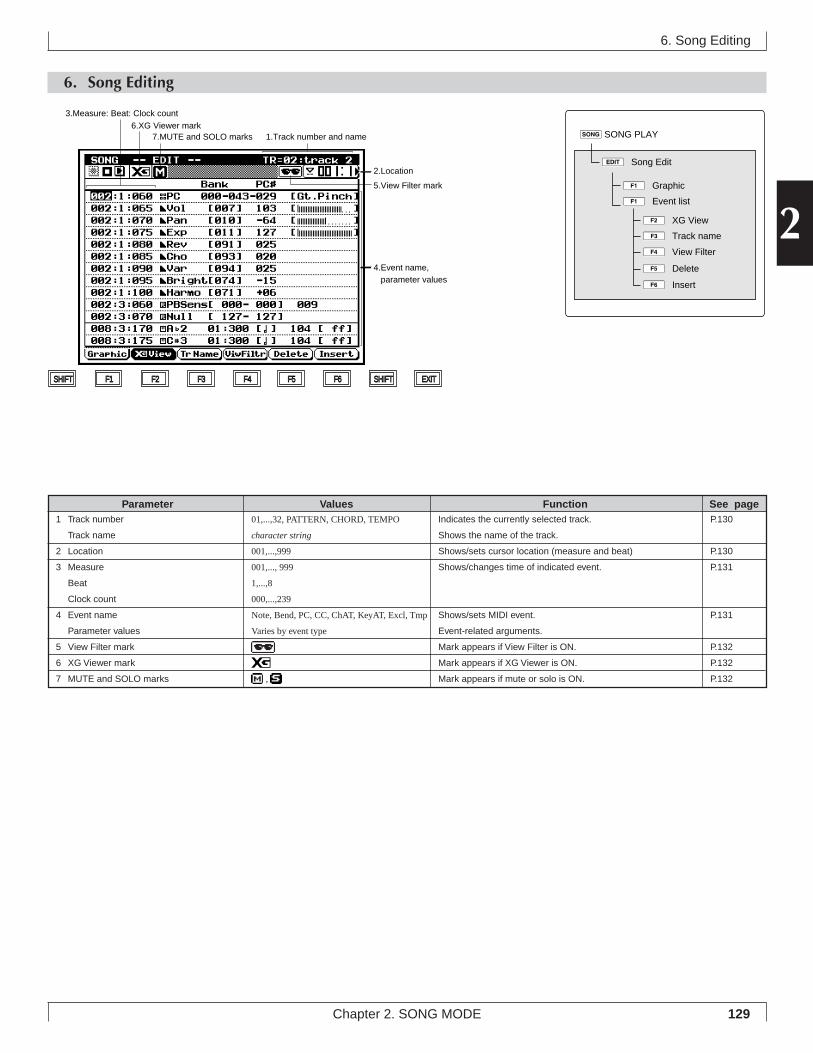
129
2
Chapter 2. SONG MODE
6. Song Editing
6. Song Editing
2.Location
7.MUTE and SOLO marks
3.Measure: Beat: Clock count6.XG Viewer mark
5.View Filter mark
SHIFT F1 F2 F3 F4 F5 F6 SHIFT EXIT
1.Track number and name
4.Event name, parameter values
sSONG PLAY
eÊSong Edit
1ÊGraphic
1ÊEvent list
3ÊTrack name
2ÊXG View
4ÊView Filter
5ÊDelete
6ÊInsert
Indicates the currently selected track.
Shows the name of the track.
Shows/sets cursor location (measure and beat)
Shows/changes time of indicated event.
Shows/sets MIDI event.
Event-related arguments.
Mark appears if View Filter is ON.
Mark appears if XG Viewer is ON.
Mark appears if mute or solo is ON.
01,...,32, PATTERN, CHORD, TEMPO
character string
001,...,999
001,..., 999
1,...,8
000,...,239
Note, Bend, PC, CC, ChAT, KeyAT, Excl, Tmp
Varies by event type
,
1 Track number
Track name
2 Location
3 Measure
Beat
Clock count
4 Event name
Parameter values
5 View Filter mark
6 XG Viewer mark
7 MUTE and SOLO marks
Parameter Values Function See pageP.130
P.130
P.131
P.131
P.132
P.132
P.132
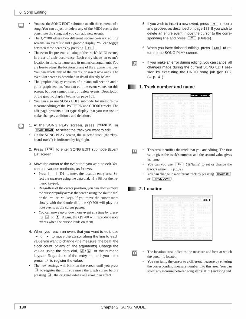
130 Chapter 2. SONG MODE
• You use the SONG EDIT submode to edit the contents of asong. You can adjust or delete any of the MIDI events thatconstitute the song, and you can add new events.
• The QY700 offers two different sequence-track editingscreens: an event list and a graphic display. You can togglebetween these screens by pressing 1.
• The event list presents a listing of the track’s MIDI events,in order of their occurrence. Each entry shows an event’slocation in time, its name, and its numerical arguments. Youare free to adjust the location or any of the argument values.You can delete any of the events, or insert new ones. Theevent-list screen is described in detail directly below.
• The graphic display consists of a piano-roll section and apoint-graph section. You can edit the event values on thisscreen, but you cannot insert or delete events. Descriptionof the graphic display begins on page 135.
• You can also use SONG EDIT submode for measure-by-measure editing of the PATTERN and CHORD tracks. Theedit page presents a list-type display that you can use tomake changes, additions, and deletions.
1. At the SONG PLAY screen, press u ord to select the track you want to edit.
• On the SONG PLAY screen, the selected track (the “key-board track”) is indicated by highlight.
2. Press e to enter SONG EDIT submode (EventList screen).
3. Move the cursor to the event that you want to edit. Youcan use various methods, as follows.• Press d [D1] to move the location entry area. Se-
lect the measure using the data dial, n/y, or the nu-meric keypad.
• Regardless of the cursor position, you can always movethe cursor rapidly across the screen using the shuttle dialor the r or f keys. If you move the cursor moreslowly with the shuttle dial, the QY700 will play outnote events as the cursor passes.
• You can move up or down one event at a time by press-ing u or d. Again, the QY700 will reproduce noteevents when the cursor lands on them.
4. When you reach an event that you want to edit, usel or r to move the cursor along the line to eachvalue you want to change (the measure, the beat, theclock count, or any of the arguments). Change thevalues using the data dial, n/y, or the numerickeypad. Regardless of the entry method, you mustpress e to register the value.
• The new settings will blink on the screen until you presse to register them. If you move the graph cursor beforepressing e, the original values will remain in effect.
5. If you wish to insert a new event, press6 (Insert)and proceed as described on page 133. If you wish todelete an entire event, move the cursor to the corre-sponding line and press 5 (Delete).
6. When you have finished editing, press e to re-turn to the SONG PLAY screen.
• If you make an error during editing, you can cancel allchanges made during the current SONG EDIT ses-sion by executing the UNDO song job (job 00).(→ p.141)
1. Track number and name
• This area identifies the track that you are editing. The firstvalue gives the track’s number, and the second value givesits name.
• You can you use 3 (TrName) to set or change thetrack’s name. (→ p.132)
• You can change to a different track by pressing u
or d.
2. Location
• The location area indicates the measure and beat at whichthe cursor is located.
• You can jump the cursor to a different measure by enteringthe corresponding measure number into this area. You canselect any measure between song start (001:1) and song end.
6. Song Editing
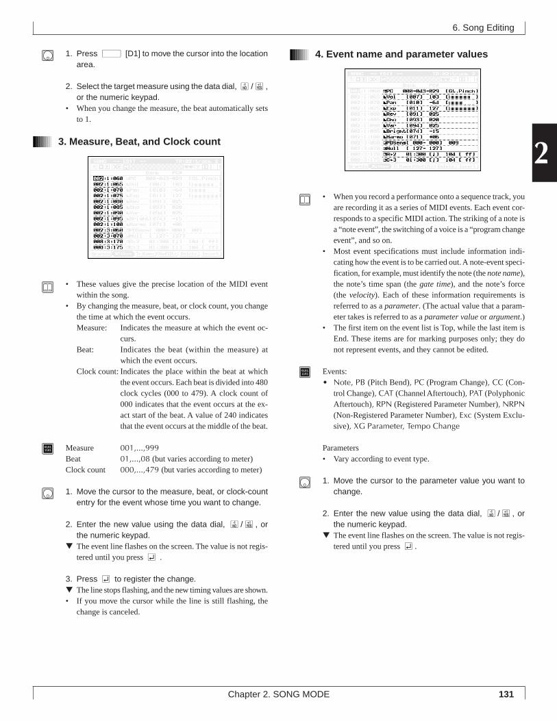
131
2
Chapter 2. SONG MODE
1. Press d [D1] to move the cursor into the locationarea.
2. Select the target measure using the data dial, n/y,or the numeric keypad.
• When you change the measure, the beat automatically setsto 1.
3. Measure, Beat, and Clock count
• These values give the precise location of the MIDI eventwithin the song.
• By changing the measure, beat, or clock count, you changethe time at which the event occurs.Measure: Indicates the measure at which the event oc-
curs.Beat: Indicates the beat (within the measure) at
which the event occurs.Clock count: Indicates the place within the beat at which
the event occurs. Each beat is divided into 480clock cycles (000 to 479). A clock count of000 indicates that the event occurs at the ex-act start of the beat. A value of 240 indicatesthat the event occurs at the middle of the beat.
01011101 Measure 001,...,999
Beat 01,...,08 (but varies according to meter)Clock count 000,...,479 (but varies according to meter)
1. Move the cursor to the measure, beat, or clock-countentry for the event whose time you want to change.
2. Enter the new value using the data dial, n/y, orthe numeric keypad.
▼ The event line flashes on the screen. The value is not regis-tered until you press e .
3. Press e to register the change.▼ The line stops flashing, and the new timing values are shown.• If you move the cursor while the line is still flashing, the
change is canceled.
4. Event name and parameter values
• When you record a performance onto a sequence track, youare recording it as a series of MIDI events. Each event cor-responds to a specific MIDI action. The striking of a note isa “note event”, the switching of a voice is a “program changeevent”, and so on.
• Most event specifications must include information indi-cating how the event is to be carried out. A note-event speci-fication, for example, must identify the note (the note name),the note’s time span (the gate time), and the note’s force(the velocity). Each of these information requirements isreferred to as a parameter. (The actual value that a param-eter takes is referred to as a parameter value or argument.)
• The first item on the event list is Top, while the last item isEnd. These items are for marking purposes only; they donot represent events, and they cannot be edited.
01011101 Events:
• Note, PB (Pitch Bend), PC (Program Change), CC (Con-trol Change), CAT (Channel Aftertouch), PAT (PolyphonicAftertouch), RPN (Registered Parameter Number), NRPN(Non-Registered Parameter Number), Exc (System Exclu-sive), XG Parameter, Tempo Change
Parameters• Vary according to event type.
1. Move the cursor to the parameter value you want tochange.
2. Enter the new value using the data dial, n/y, orthe numeric keypad.
▼ The event line flashes on the screen. The value is not regis-tered until you press e.
6. Song Editing
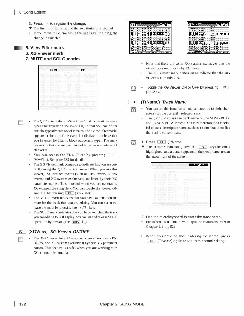
132 Chapter 2. SONG MODE
3. Press e to register the change.▼ The line stops flashing, and the new timing is indicated.• If you move the cursor while the line is still flashing, the
change is canceled.
5. View Filter mark6. XG Viewer mark7. MUTE and SOLO marks
• The QY700 includes a “View Filter” that can limit the eventtypes that appear on the event list, so that you can “filterout” the types that are not of interest. The “View Filter mark”appears at the top of the event-list display to indicate thatyou have set the filter to block out certain types. The markwarns you that you may not be looking at a complete list ofall events.
• You can access the View Filter by pressing 4
(ViwFiltr). See page 133 for details.• The XG Viewer mark comes on to indicate that you are cur-
rently using the QY700’s XG viewer. When you use thisviewer, XG-defined events (such as RPN events, NRPNevents, and XG system exclusives) are listed by their XGparameter names. This is useful when you are generatingXG-compatible song data. You can toggle the viewer ONand OFF by pressing 2(XGView).
• The MUTE mark indicates that you have switched on themute for the track that you are editing. You can set or re-lease the mute by pressing the m key.
• The SOLO mark indicates that you have switched the trackyou are editing to SOLO play. You can set and release SOLOoperation by pressing the s key.
2 (XGView) XG Viewer ON/OFF• The XG Viewer lists XG-defined events (such as RPN,
NRPN, and XG system exclusives) by their XG parameternames. This feature is useful when you are working withXG-compatible song data.
• Note that there are some XG system exclusives that theviewer does not display by XG name.
• The XG Viewer mark comes on to indicate that the XGviewer is currently ON.
• Toggle the XG Viewer ON or OFF by pressing 2(XGView).
3 (TrName) Track Name• You can use this function to enter a name (up to eight char-
acters) for the currently selected track.• The QY700 displays the track name on the SONG PLAY
and TRACK VIEW screens. You may therefore find it help-ful to use a descriptive name, such as a name that identifiesthe track’s voice or part.
1. Press 3 (TrName).▼ The TrName indicator (above the 3 key) becomes
highlighted, and a cursor appears in the track-name area atthe upper right of the screen.
2. Use the microkeyboard to enter the track name.• For information about how to input the characters, refer to
Chapter 1. (→ p.53)
3. When you have finished entering the name, press3 (TrName) again to return to normal editing.
6. Song Editing
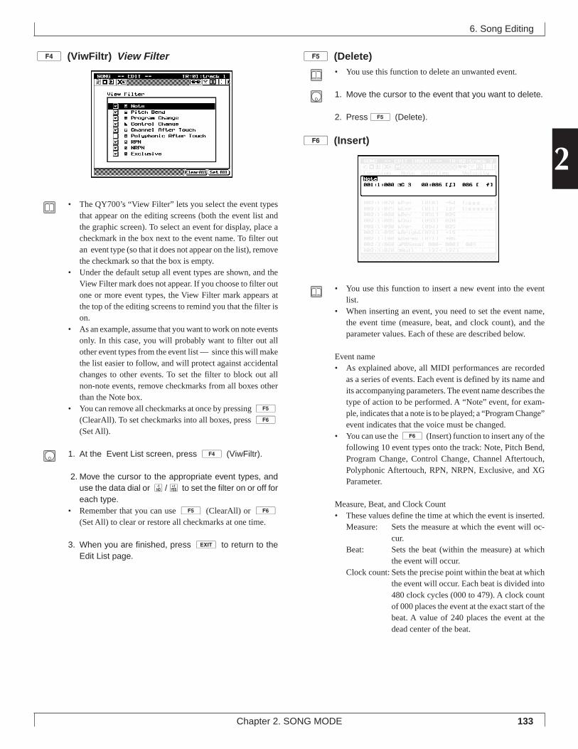
133
2
Chapter 2. SONG MODE
4 (ViwFiltr) View Filter
• The QY700’s “View Filter” lets you select the event typesthat appear on the editing screens (both the event list andthe graphic screen). To select an event for display, place acheckmark in the box next to the event name. To filter outan event type (so that it does not appear on the list), removethe checkmark so that the box is empty.
• Under the default setup all event types are shown, and theView Filter mark does not appear. If you choose to filter outone or more event types, the View Filter mark appears atthe top of the editing screens to remind you that the filter ison.
• As an example, assume that you want to work on note eventsonly. In this case, you will probably want to filter out allother event types from the event list — since this will makethe list easier to follow, and will protect against accidentalchanges to other events. To set the filter to block out allnon-note events, remove checkmarks from all boxes otherthan the Note box.
• You can remove all checkmarks at once by pressing 5
(ClearAll). To set checkmarks into all boxes, press 6
(Set All).
1. At the Event List screen, press 4 (ViwFiltr).
2. Move the cursor to the appropriate event types, anduse the data dial or n/y to set the filter on or off foreach type.
• Remember that you can use 5 (ClearAll) or 6(Set All) to clear or restore all checkmarks at one time.
3. When you are finished, press e to return to theEdit List page.
5 (Delete)• You use this function to delete an unwanted event.
1. Move the cursor to the event that you want to delete.
2. Press5 (Delete).
6 (Insert)
• You use this function to insert a new event into the eventlist.
• When inserting an event, you need to set the event name,the event time (measure, beat, and clock count), and theparameter values. Each of these are described below.
Event name• As explained above, all MIDI performances are recorded
as a series of events. Each event is defined by its name andits accompanying parameters. The event name describes thetype of action to be performed. A “Note” event, for exam-ple, indicates that a note is to be played; a “Program Change”event indicates that the voice must be changed.
• You can use the 6 (Insert) function to insert any of thefollowing 10 event types onto the track: Note, Pitch Bend,Program Change, Control Change, Channel Aftertouch,Polyphonic Aftertouch, RPN, NRPN, Exclusive, and XGParameter.
Measure, Beat, and Clock Count• These values define the time at which the event is inserted.
Measure: Sets the measure at which the event will oc-cur.
Beat: Sets the beat (within the measure) at whichthe event will occur.
Clock count: Sets the precise point within the beat at whichthe event will occur. Each beat is divided into480 clock cycles (000 to 479). A clock countof 000 places the event at the exact start of thebeat. A value of 240 places the event at thedead center of the beat.
6. Song Editing
134 Chapter 2. SONG MODE
• On the QY700, you can set the measure to any value be-tween 001 and 999. The allowable beat and time values varyaccording to the selected time meter. The maximum rangefor the beat is 01 to 16. The maximum range for the clockcount is 000 to 479.
Parameter values• As described above (→ p.131), each event is defined by its
type and by its accompanying parameter values. When en-tering an event type, you must include parameter values in-dicating how it is to be carried out. If entering a note event,for example, you must include values for velocity (noteforce) and gate time (note playback time).
• Required parameters are different for each event type.
1. At the Event List screen, press 6 (Insert).▼ The QY700 displays the “INSERT” window.
2. Move the cursor to the item that you want to set (eventname, measure, beat, clock count, or parameter).
3. Set the value using the data dial, n/y, or the nu-meric keypad.
• If you are using the numeric keypad, do not press e untilyou have finished entering all values and have checked themfor correctness. Let the values remain flashing on the screenuntil you have completed all of the settings.
4. When you have finished entering all values for theevent, press e to record the event onto the track.
• As a shortcut, you can press e as many times as you liketo insert multiple copies of the same event. You can then goback to the event-list page and edit these entries as neces-sary.
• If you wish to set up and insert another event, return to Step2 above.
5. When you have finished, press e to return to theEVENT LIST page. Check the listing to make sure thatthe events were correctly inserted.
Entering a System Exclusive at the INSERT window.• Use the following procedure to insert a system exclusive
when working at the INSERT window.
1. Select Exc as the event name. Set the measure, beat,and clock count at which you want the exclusive tooccur.
2. Move the cursor to the parameter area. Enter the hexa-decimal values, moving the cursor from value to valueas necessary.
• You can enter the hexadecimal numbers using n/y orthe data dial. You can also enter them with the numerickeypad: use the pad keys to enter digits from 0 to 9, andmicrokeyboard keys [F
#2], [G
#2], [A
#2], [C
#3], [D
#3], [F
#3]
to input digits A to F, respectively. (But don’t press e
until you have completed entry of all values.)• Be sure to enter value F7 (“End of Exclusive”) as the final
data item.
3. When you have entered all values for the system ex-clusive, presse to record it onto the track.
• As a shortcut, you can press e to insert multiple copies ofthe same system exclusive. You can then go back to the event-list page and edit the values as necessary.
• If you wish to insert another, different system exclusive,return to Step 2 above.
4. When you have finished, press e to return to theEVENT LIST page. Check the listing to make sure thatthe new system exclusives are correct.
6. Song Editing
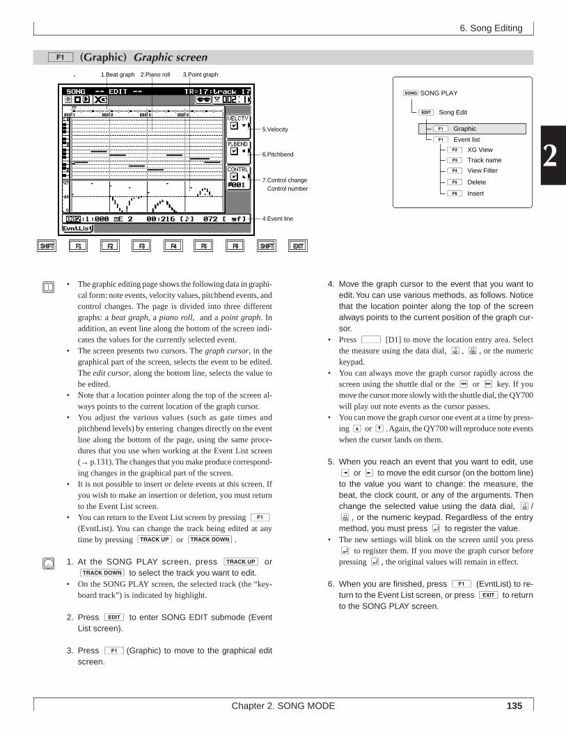
135
2
Chapter 2. SONG MODE
1 (Graphic) Graphic screen
6. Song Editing
4. Move the graph cursor to the event that you want toedit. You can use various methods, as follows. Noticethat the location pointer along the top of the screenalways points to the current position of the graph cur-sor.
• Press d [D1] to move the location entry area. Selectthe measure using the data dial, n, y, or the numerickeypad.
• You can always move the graph cursor rapidly across thescreen using the shuttle dial or the r or f key. If youmove the cursor more slowly with the shuttle dial, the QY700will play out note events as the cursor passes.
• You can move the graph cursor one event at a time by press-ing u or d. Again, the QY700 will reproduce note eventswhen the cursor lands on them.
5. When you reach an event that you want to edit, usel or r to move the edit cursor (on the bottom line)to the value you want to change: the measure, thebeat, the clock count, or any of the arguments. Thenchange the selected value using the data dial, n/y, or the numeric keypad. Regardless of the entrymethod, you must press e to register the value.
• The new settings will blink on the screen until you presse to register them. If you move the graph cursor beforepressing e, the original values will remain in effect.
6. When you are finished, press 1 (EvntList) to re-turn to the Event List screen, or press e to returnto the SONG PLAY screen.
• The graphic editing page shows the following data in graphi-cal form: note events, velocity values, pitchbend events, andcontrol changes. The page is divided into three differentgraphs: a beat graph, a piano roll, and a point graph. Inaddition, an event line along the bottom of the screen indi-cates the values for the currently selected event.
• The screen presents two cursors. The graph cursor, in thegraphical part of the screen, selects the event to be edited.The edit cursor, along the bottom line, selects the value tobe edited.
• Note that a location pointer along the top of the screen al-ways points to the current location of the graph cursor.
• You adjust the various values (such as gate times andpitchbend levels) by entering changes directly on the eventline along the bottom of the page, using the same proce-dures that you use when working at the Event List screen(→ p.131). The changes that you make produce correspond-ing changes in the graphical part of the screen.
• It is not possible to insert or delete events at this screen. Ifyou wish to make an insertion or deletion, you must returnto the Event List screen.
• You can return to the Event List screen by pressing 1
(EvntList). You can change the track being edited at anytime by pressing u or d.
1. At the SONG PLAY screen, press u ord to select the track you want to edit.
• On the SONG PLAY screen, the selected track (the “key-board track”) is indicated by highlight.
2. Press e to enter SONG EDIT submode (EventList screen).
3. Press 1 (Graphic) to move to the graphical editscreen.
sSONG PLAY
eÊSong Edit
1ÊGraphic
1ÊEvent list
3ÊTrack name
2ÊXG View
4ÊView Filter
5ÊDelete
6ÊInsert
5.Velocity
6.Pitchbend
7.Control change Control number
4.Event line
1.Beat graph 2.Piano roll
SHIFT F1 F2 F3 F4 F5 F6 SHIFT EXIT
3.Point graph
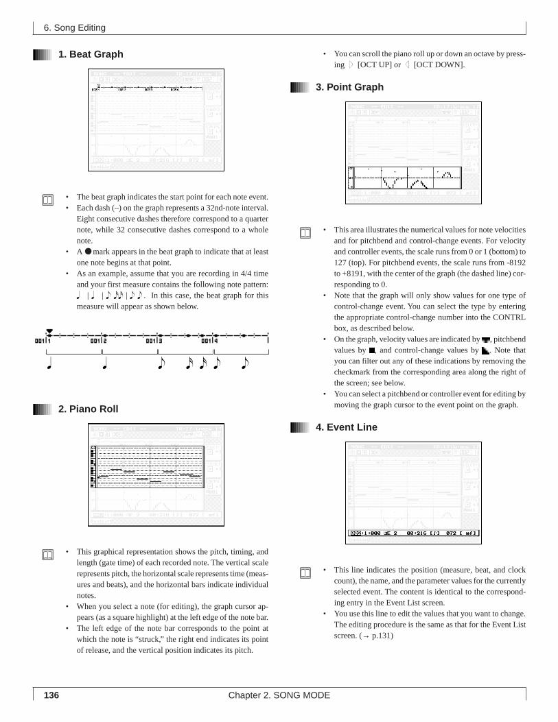
136 Chapter 2. SONG MODE
1. Beat Graph
• The beat graph indicates the start point for each note event.• Each dash (–) on the graph represents a 32nd-note interval.
Eight consecutive dashes therefore correspond to a quarternote, while 32 consecutive dashes correspond to a wholenote.
• A ● mark appears in the beat graph to indicate that at leastone note begins at that point.
• As an example, assume that you are recording in 4/4 timeand your first measure contains the following note pattern:q | q | e xx | e e . In this case, the beat graph for thismeasure will appear as shown below.
2. Piano Roll
• This graphical representation shows the pitch, timing, andlength (gate time) of each recorded note. The vertical scalerepresents pitch, the horizontal scale represents time (meas-ures and beats), and the horizontal bars indicate individualnotes.
• When you select a note (for editing), the graph cursor ap-pears (as a square highlight) at the left edge of the note bar.
• The left edge of the note bar corresponds to the point atwhich the note is “struck,” the right end indicates its pointof release, and the vertical position indicates its pitch.
• You can scroll the piano roll up or down an octave by press-ing u [OCT UP] or d [OCT DOWN].
3. Point Graph
• This area illustrates the numerical values for note velocitiesand for pitchbend and control-change events. For velocityand controller events, the scale runs from 0 or 1 (bottom) to127 (top). For pitchbend events, the scale runs from -8192to +8191, with the center of the graph (the dashed line) cor-responding to 0.
• Note that the graph will only show values for one type ofcontrol-change event. You can select the type by enteringthe appropriate control-change number into the CONTRLbox, as described below.
• On the graph, velocity values are indicated by , pitchbendvalues by , and control-change values by . Note thatyou can filter out any of these indications by removing thecheckmark from the corresponding area along the right ofthe screen; see below.
• You can select a pitchbend or controller event for editing bymoving the graph cursor to the event point on the graph.
4. Event Line
• This line indicates the position (measure, beat, and clockcount), the name, and the parameter values for the currentlyselected event. The content is identical to the correspond-ing entry in the Event List screen.
• You use this line to edit the values that you want to change.The editing procedure is the same as that for the Event Listscreen. (→ p.131)
6. Song Editing
eq q ex x e
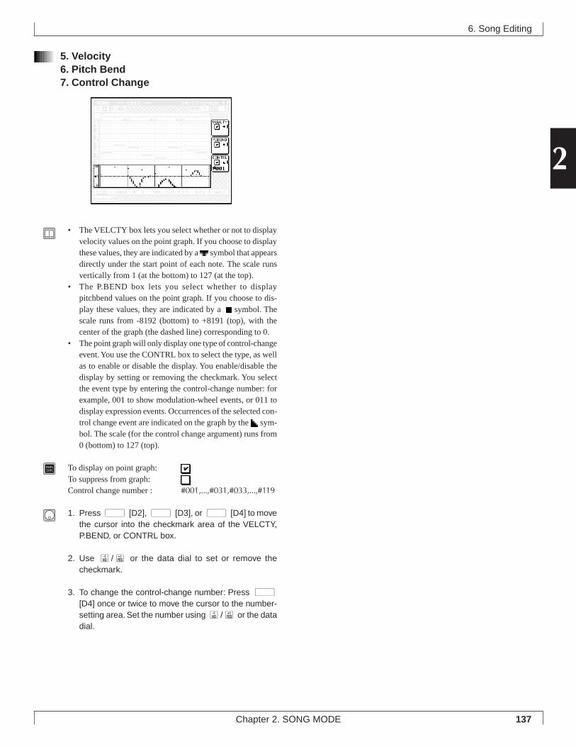
137
2
Chapter 2. SONG MODE
5. Velocity6. Pitch Bend7. Control Change
• The VELCTY box lets you select whether or not to displayvelocity values on the point graph. If you choose to displaythese values, they are indicated by a symbol that appearsdirectly under the start point of each note. The scale runsvertically from 1 (at the bottom) to 127 (at the top).
• The P.BEND box lets you select whether to displaypitchbend values on the point graph. If you choose to dis-play these values, they are indicated by a symbol. Thescale runs from -8192 (bottom) to +8191 (top), with thecenter of the graph (the dashed line) corresponding to 0.
• The point graph will only display one type of control-changeevent. You use the CONTRL box to select the type, as wellas to enable or disable the display. You enable/disable thedisplay by setting or removing the checkmark. You selectthe event type by entering the control-change number: forexample, 001 to show modulation-wheel events, or 011 todisplay expression events. Occurrences of the selected con-trol change event are indicated on the graph by the sym-bol. The scale (for the control change argument) runs from0 (bottom) to 127 (top).
01011101 To display on point graph:
To suppress from graph:Control change number : #001,...,#031,#033,...,#119
1. Press d [D2], d [D3], or d [D4] to movethe cursor into the checkmark area of the VELCTY,P.BEND, or CONTRL box.
2. Use n/y or the data dial to set or remove thecheckmark.
3. To change the control-change number: Press d[D4] once or twice to move the cursor to the number-setting area. Set the number using n/y or the datadial.
6. Song Editing
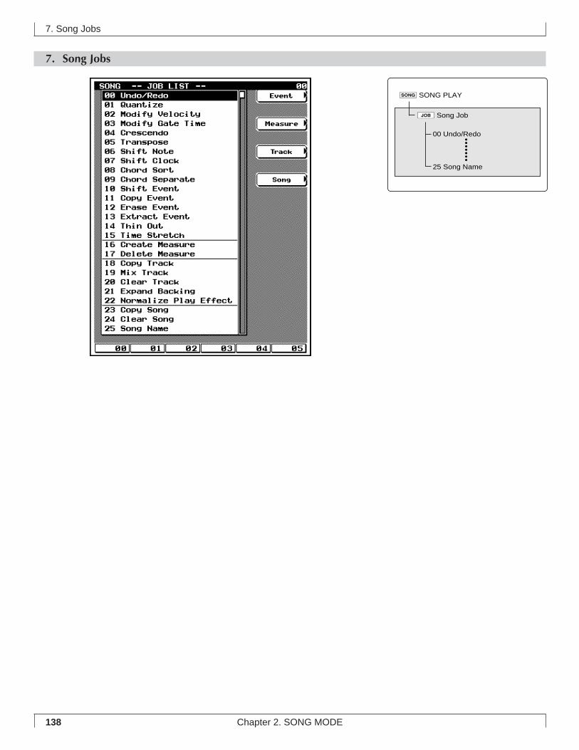
138 Chapter 2. SONG MODE
7. Song Jobs
7. Song Jobs
00 Undo/Redo
25 Song Name
sSONG PLAY
jSong Job
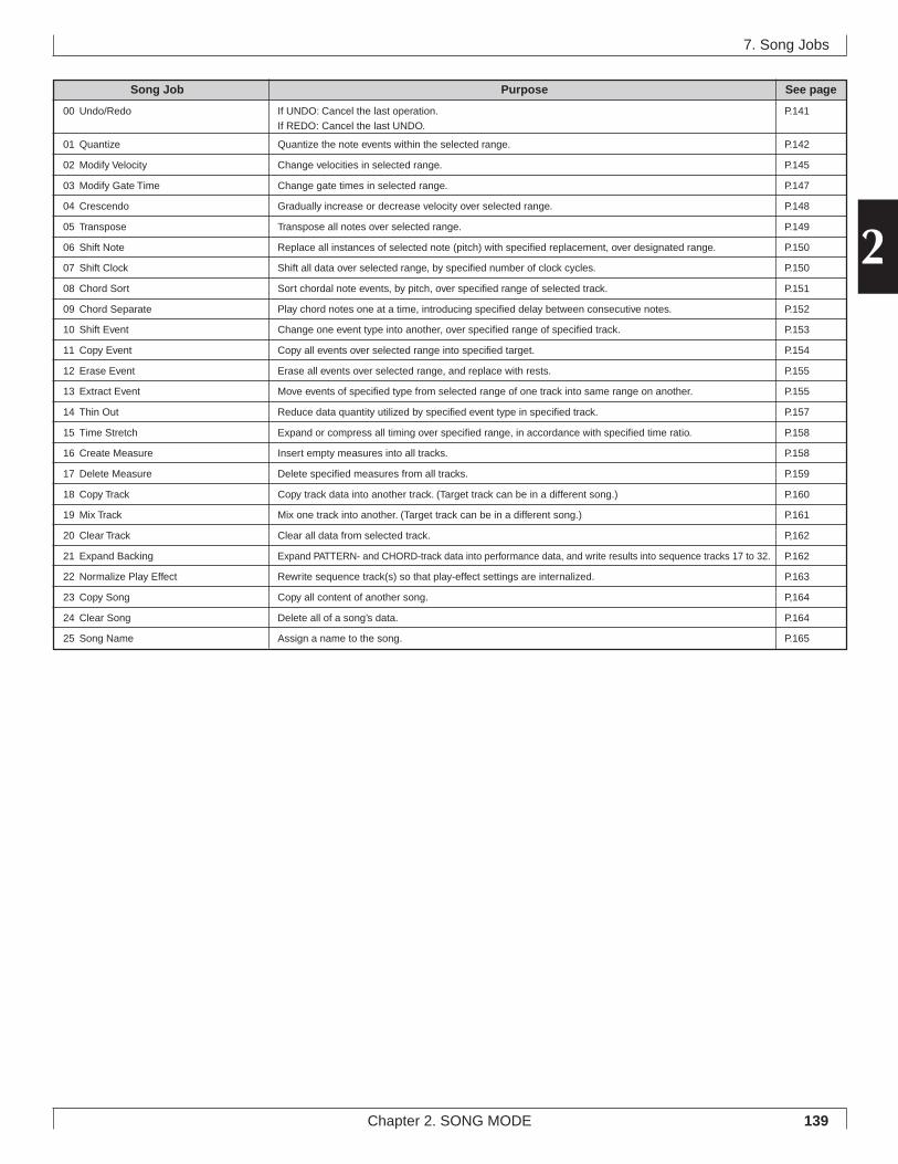
139
2
Chapter 2. SONG MODE
7. Song Jobs
Song Job Purpose See page
00 Undo/Redo If UNDO: Cancel the last operation. P.141If REDO: Cancel the last UNDO.
01 Quantize Quantize the note events within the selected range. P.142
02 Modify Velocity Change velocities in selected range. P.145
03 Modify Gate Time Change gate times in selected range. P.147
04 Crescendo Gradually increase or decrease velocity over selected range. P.148
05 Transpose Transpose all notes over selected range. P.149
06 Shift Note Replace all instances of selected note (pitch) with specified replacement, over designated range. P.150
07 Shift Clock Shift all data over selected range, by specified number of clock cycles. P.150
08 Chord Sort Sort chordal note events, by pitch, over specified range of selected track. P.151
09 Chord Separate Play chord notes one at a time, introducing specified delay between consecutive notes. P.152
10 Shift Event Change one event type into another, over specified range of specified track. P.153
11 Copy Event Copy all events over selected range into specified target. P.154
12 Erase Event Erase all events over selected range, and replace with rests. P.155
13 Extract Event Move events of specified type from selected range of one track into same range on another. P.155
14 Thin Out Reduce data quantity utilized by specified event type in specified track. P.157
15 Time Stretch Expand or compress all timing over specified range, in accordance with specified time ratio. P.158
16 Create Measure Insert empty measures into all tracks. P.158
17 Delete Measure Delete specified measures from all tracks. P.159
18 Copy Track Copy track data into another track. (Target track can be in a different song.) P.160
19 Mix Track Mix one track into another. (Target track can be in a different song.) P.161
20 Clear Track Clear all data from selected track. P,162
21 Expand Backing Expand PATTERN- and CHORD-track data into performance data, and write results into sequence tracks 17 to 32. P.162
22 Normalize Play Effect Rewrite sequence track(s) so that play-effect settings are internalized. P.163
23 Copy Song Copy all content of another song. P,164
24 Clear Song Delete all of a song’s data. P.164
25 Song Name Assign a name to the song. P.165
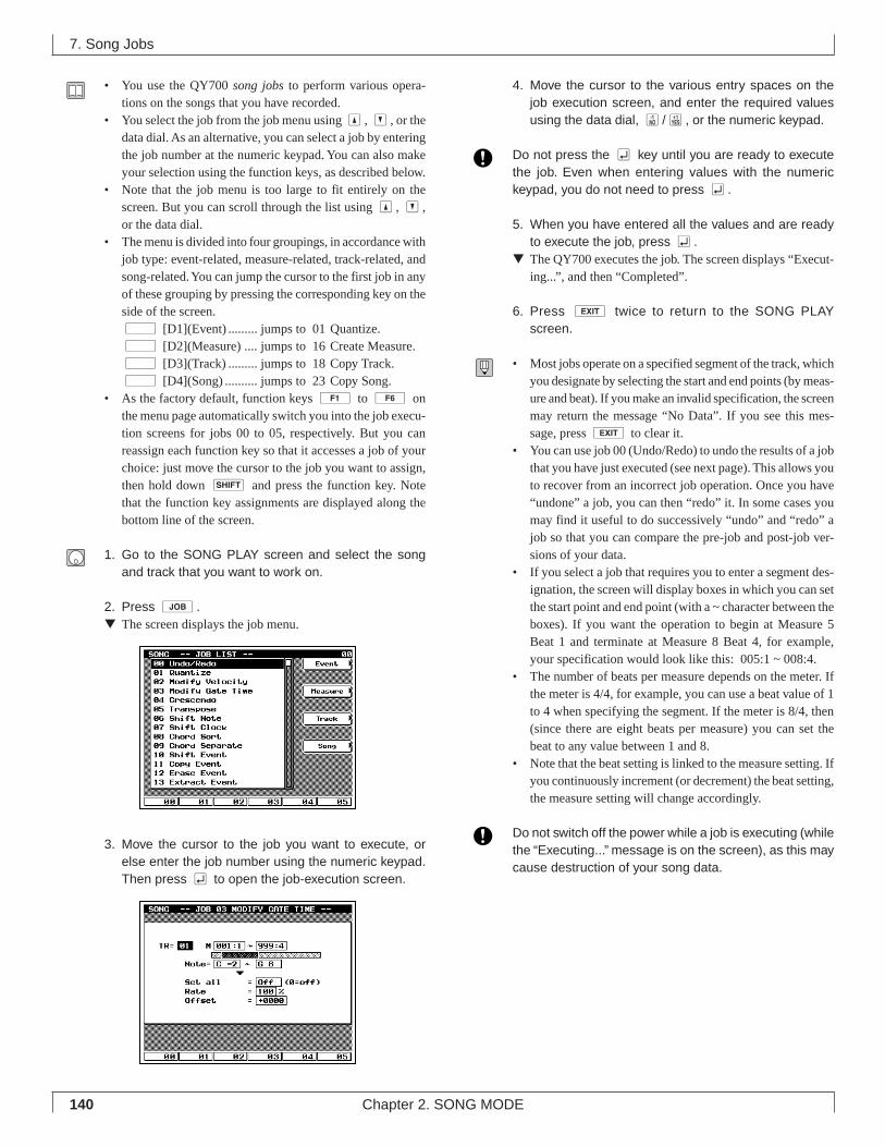
140 Chapter 2. SONG MODE
• You use the QY700 song jobs to perform various opera-tions on the songs that you have recorded.
• You select the job from the job menu using u, d, or thedata dial. As an alternative, you can select a job by enteringthe job number at the numeric keypad. You can also makeyour selection using the function keys, as described below.
• Note that the job menu is too large to fit entirely on thescreen. But you can scroll through the list using u, d,or the data dial.
• The menu is divided into four groupings, in accordance withjob type: event-related, measure-related, track-related, andsong-related. You can jump the cursor to the first job in anyof these grouping by pressing the corresponding key on theside of the screen.d [D1](Event) ......... jumps to 01 Quantize.d [D2](Measure) .... jumps to 16 Create Measure.d [D3](Track) ......... jumps to 18 Copy Track.d [D4](Song) .......... jumps to 23 Copy Song.
• As the factory default, function keys 1 to 6 onthe menu page automatically switch you into the job execu-tion screens for jobs 00 to 05, respectively. But you canreassign each function key so that it accesses a job of yourchoice: just move the cursor to the job you want to assign,then hold down s and press the function key. Notethat the function key assignments are displayed along thebottom line of the screen.
1. Go to the SONG PLAY screen and select the songand track that you want to work on.
2. Press j.▼ The screen displays the job menu.
3. Move the cursor to the job you want to execute, orelse enter the job number using the numeric keypad.Then press e to open the job-execution screen.
4. Move the cursor to the various entry spaces on thejob execution screen, and enter the required valuesusing the data dial, n/y, or the numeric keypad.
Do not press the e key until you are ready to executethe job. Even when entering values with the numerickeypad, you do not need to press e.
5. When you have entered all the values and are readyto execute the job, press e.
▼ The QY700 executes the job. The screen displays “Execut-ing...”, and then “Completed”.
6. Press e twice to return to the SONG PLAYscreen.
• Most jobs operate on a specified segment of the track, whichyou designate by selecting the start and end points (by meas-ure and beat). If you make an invalid specification, the screenmay return the message “No Data”. If you see this mes-sage, press e to clear it.
• You can use job 00 (Undo/Redo) to undo the results of a jobthat you have just executed (see next page). This allows youto recover from an incorrect job operation. Once you have“undone” a job, you can then “redo” it. In some cases youmay find it useful to do successively “undo” and “redo” ajob so that you can compare the pre-job and post-job ver-sions of your data.
• If you select a job that requires you to enter a segment des-ignation, the screen will display boxes in which you can setthe start point and end point (with a ~ character between theboxes). If you want the operation to begin at Measure 5Beat 1 and terminate at Measure 8 Beat 4, for example,your specification would look like this: 005:1 ~ 008:4.
• The number of beats per measure depends on the meter. Ifthe meter is 4/4, for example, you can use a beat value of 1to 4 when specifying the segment. If the meter is 8/4, then(since there are eight beats per measure) you can set thebeat to any value between 1 and 8.
• Note that the beat setting is linked to the measure setting. Ifyou continuously increment (or decrement) the beat setting,the measure setting will change accordingly.
Do not switch off the power while a job is executing (whilethe “Executing...” message is on the screen), as this maycause destruction of your song data.
7. Song Jobs
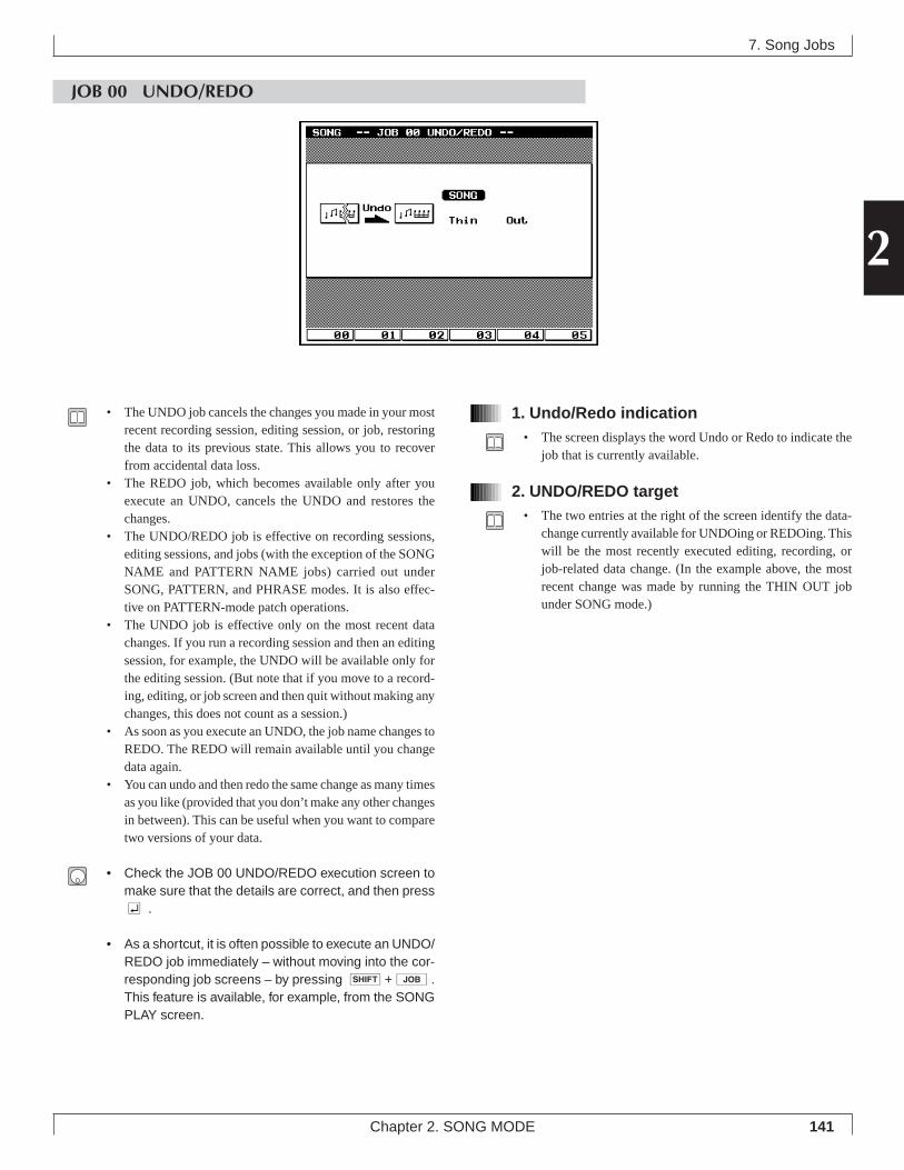
141
2
Chapter 2. SONG MODE
7. Song Jobs
JOB 00 UNDO/REDO
1. Undo/Redo indication• The screen displays the word Undo or Redo to indicate the
job that is currently available.
2. UNDO/REDO target• The two entries at the right of the screen identify the data-
change currently available for UNDOing or REDOing. Thiswill be the most recently executed editing, recording, orjob-related data change. (In the example above, the mostrecent change was made by running the THIN OUT jobunder SONG mode.)
• The UNDO job cancels the changes you made in your mostrecent recording session, editing session, or job, restoringthe data to its previous state. This allows you to recoverfrom accidental data loss.
• The REDO job, which becomes available only after youexecute an UNDO, cancels the UNDO and restores thechanges.
• The UNDO/REDO job is effective on recording sessions,editing sessions, and jobs (with the exception of the SONGNAME and PATTERN NAME jobs) carried out underSONG, PATTERN, and PHRASE modes. It is also effec-tive on PATTERN-mode patch operations.
• The UNDO job is effective only on the most recent datachanges. If you run a recording session and then an editingsession, for example, the UNDO will be available only forthe editing session. (But note that if you move to a record-ing, editing, or job screen and then quit without making anychanges, this does not count as a session.)
• As soon as you execute an UNDO, the job name changes toREDO. The REDO will remain available until you changedata again.
• You can undo and then redo the same change as many timesas you like (provided that you don’t make any other changesin between). This can be useful when you want to comparetwo versions of your data.
• Check the JOB 00 UNDO/REDO execution screen tomake sure that the details are correct, and then presse .
• As a shortcut, it is often possible to execute an UNDO/REDO job immediately – without moving into the cor-responding job screens – by pressing s+j.This feature is available, for example, from the SONGPLAY screen.
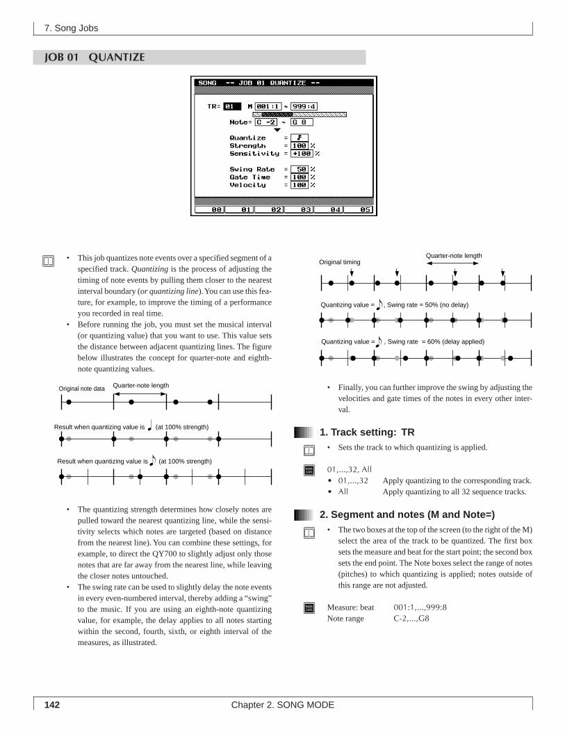
142 Chapter 2. SONG MODE
7. Song Jobs
JOB 01 QUANTIZE
• Finally, you can further improve the swing by adjusting thevelocities and gate times of the notes in every other inter-val.
1. Track setting: TR• Sets the track to which quantizing is applied.
01011101 01,...,32, All
• 01,...,32 Apply quantizing to the corresponding track.• All Apply quantizing to all 32 sequence tracks.
2. Segment and notes (M and Note=)• The two boxes at the top of the screen (to the right of the M)
select the area of the track to be quantized. The first boxsets the measure and beat for the start point; the second boxsets the end point. The Note boxes select the range of notes(pitches) to which quantizing is applied; notes outside ofthis range are not adjusted.
01011101 Measure: beat 001:1,...,999:8
Note range C-2,...,G8
• This job quantizes note events over a specified segment of aspecified track. Quantizing is the process of adjusting thetiming of note events by pulling them closer to the nearestinterval boundary (or quantizing line). You can use this fea-ture, for example, to improve the timing of a performanceyou recorded in real time.
• Before running the job, you must set the musical interval(or quantizing value) that you want to use. This value setsthe distance between adjacent quantizing lines. The figurebelow illustrates the concept for quarter-note and eighth-note quantizing values.
• The quantizing strength determines how closely notes arepulled toward the nearest quantizing line, while the sensi-tivity selects which notes are targeted (based on distancefrom the nearest line). You can combine these settings, forexample, to direct the QY700 to slightly adjust only thosenotes that are far away from the nearest line, while leavingthe closer notes untouched.
• The swing rate can be used to slightly delay the note eventsin every even-numbered interval, thereby adding a “swing”to the music. If you are using an eighth-note quantizingvalue, for example, the delay applies to all notes startingwithin the second, fourth, sixth, or eighth interval of themeasures, as illustrated.
Original note data Quarter-note length
Result when quantizing value is (at 100% strength)
Result when quantizing value is (at 100% strength)
Original timing
Quantizing value = , Swing rate = 50% (no delay)
Quantizing value = , Swing rate = 60% (delay applied)
Quarter-note length
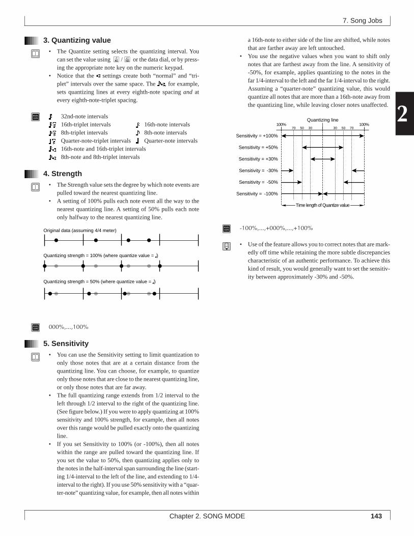
143
2
Chapter 2. SONG MODE
3. Quantizing value• The Quantize setting selects the quantizing interval. You
can set the value using n/y or the data dial, or by press-ing the appropriate note key on the numeric keypad.
• Notice that the settings create both “normal” and “tri-plet” intervals over the same space. The , for example,sets quantizing lines at every eighth-note spacing and atevery eighth-note-triplet spacing.
01011101 32nd-note intervals
16th-triplet intervals 16th-note intervals8th-triplet intervals 8th-note intervalsQuarter-note-triplet intervals Quarter-note intervals16th-note and 16th-triplet intervals8th-note and 8th-triplet intervals
4. Strength• The Strength value sets the degree by which note events are
pulled toward the nearest quantizing line.• A setting of 100% pulls each note event all the way to the
nearest quantizing line. A setting of 50% pulls each noteonly halfway to the nearest quantizing line.
01011101 000%,...,100%
5. Sensitivity• You can use the Sensitivity setting to limit quantization to
only those notes that are at a certain distance from thequantizing line. You can choose, for example, to quantizeonly those notes that are close to the nearest quantizing line,or only those notes that are far away.
• The full quantizing range extends from 1/2 interval to theleft through 1/2 interval to the right of the quantizing line.(See figure below.) If you were to apply quantizing at 100%sensitivity and 100% strength, for example, then all notesover this range would be pulled exactly onto the quantizingline.
• If you set Sensitivity to 100% (or -100%), then all noteswithin the range are pulled toward the quantizing line. Ifyou set the value to 50%, then quantizing applies only tothe notes in the half-interval span surrounding the line (start-ing 1/4-interval to the left of the line, and extending to 1/4-interval to the right). If you use 50% sensitivity with a “quar-ter-note” quantizing value, for example, then all notes within
a 16th-note to either side of the line are shifted, while notesthat are farther away are left untouched.
• You use the negative values when you want to shift onlynotes that are farthest away from the line. A sensitivity of-50%, for example, applies quantizing to the notes in thefar 1/4-interval to the left and the far 1/4-interval to the right.Assuming a “quarter-note” quantizing value, this wouldquantize all notes that are more than a 16th-note away fromthe quantizing line, while leaving closer notes unaffected.
01011101 -100%,...,+000%,...,+100%
• Use of the feature allows you to correct notes that are mark-edly off time while retaining the more subtle discrepanciescharacteristic of an authentic performance. To achieve thiskind of result, you would generally want to set the sensitiv-ity between approximately -30% and -50%.
7. Song Jobs
Sensitivity = +100%
Sensitivity = +50%
Sensitivity = +30%
Sensitivity = -30%
Sensitivity = -50%
Sensitivity = -100%
100%Quantizing line
100%30 3050 5070 70
Time length of Quantize value
Original data (assuming 4/4 meter)
Quantizing strength = 50% (where quantize value = q)
Quantizing strength = 100% (where quantize value = q)
144 Chapter 2. SONG MODE
6. Swing rate• This setting lets you apply a delay to the notes in every
even-numbered quantizing interval (but see below) to pro-duce a more swinging rhythm. This adjustment is carriedout after quantizing is completed: first the notes arequantized, and then the swing delay (if any) is applied.
• If you are using a 32nd, 16th, 8th, or quarter-note quantizingvalue, the QY700 applies the delay to every even-numberedinterval. If you are using an 8th-note, for example, then thenotes in the first 8th-note interval are normal, the notes inthe second 8th-note interval are delayed, the notes in thirdinterval are normal, and so on.
• If you are using one of the triplet quantizing values, thenthe QY700 applies the delay to the notes in every third in-terval. If you are using the or quantizing value, theQY700 applies the delay to the non-triplet part of the rhythmonly (to the or rhythm only).
• The “swing rate” is given as a scale value indicating theposition for the shifted “beat.” For non-triplet rhythms, avalue of 50% leaves the position unchanged, while highervalues apply a delay. (In this case, 100% represents doublethe length of the quantizing interval.) The available settingsdepend on the rhythm type, as described below.
• For the quantizing values indicated above, a 50% settingproduces no adjustment, so that the even-numbered inter-val remains exactly centered. Higher values shift the inter-val to the right, to produce an added swing. The maximumsetting is 75%, which shifts the interval by an amount equalto one-half the quantizing value.
• With the triplet quantizing values (see above), the QY700applies the shift to the third interval only. In this case, a66% setting produces no adjustment (so that the third inter-val remains at its original position). Higher values shift theinterval to the right. The maximum setting is 83%, whichshifts the interval by an amount equal to one-half thequantizing value. (Notice that in this case, the 100% scalerepresents three times the quantizing length.)
7. Song Jobs
• In the case of normal-plus-triplet quantizing values, theQY700 applies the shift only to the non-triplet part of therhythm, as illustrated above. In this case, a setting of 50%produces no shift, while higher values shift the even inter-val to the right. Note that the maximum setting is 66%, whichmoves the interval all the way up to the position of the thirdnote in the triplet rhythm. (The 100% scale represents dou-ble the or quantizing length.)
01011101 • If quantizing value is , , , : 50%,...,75%
• If quantizing value is , or : 66%,...,83%• If quantizing value is or : 50%,...,66%
• If you set STRENGTH below 100%, notes may lie at arbi-trary locations within the interval prior to the “swing-rate”shift. In this case, the QY700 will slide all of the notes withinthe interval by an equal amount.
• Where STRENGTH is less than 100%, therefore, it is pos-sible that the swing adjustment may push some notes intothe next interval. If the QY700 must push a note beyondone or more notes lying in the next interval, it will shiftthese other notes to the same location as well.
7. Swing Gate Time• This value applies a proportional adjustment to the gate tim-
ing of the notes within the swing-adjusted intervals.• The gate time is the length of time that a note is held. You
can use this setting, therefore, to lengthen or shorten thenotes in the swing-adjusted intervals.
• A setting of 100% leaves the original gate time unchanged.Higher settings increase the gate time, while lower settingsshorten it.
• If an adjusted gate-time value is less than 1, the QY700 setsthe value to 1.
01011101 000%,...,100%,...,200%
Where quantizing value is , , or :
0% 50% 75% 100%
Setting range
Where quantizing value is , or :
0% 66%33% 83% 100%
Setting range
Where quantizing value is , :
0% 50%33% 66% 100%
Setting range
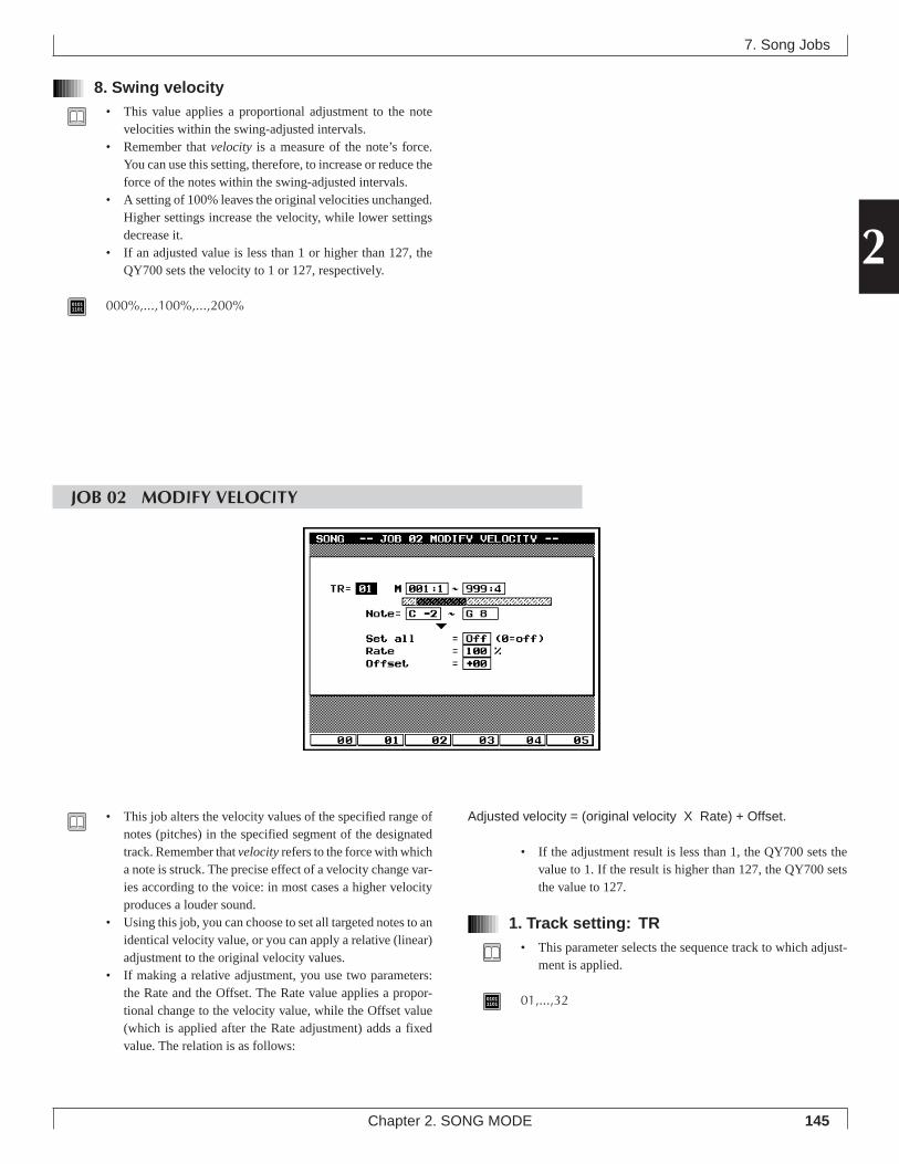
145
2
Chapter 2. SONG MODE
8. Swing velocity• This value applies a proportional adjustment to the note
velocities within the swing-adjusted intervals.• Remember that velocity is a measure of the note’s force.
You can use this setting, therefore, to increase or reduce theforce of the notes within the swing-adjusted intervals.
• A setting of 100% leaves the original velocities unchanged.Higher settings increase the velocity, while lower settingsdecrease it.
• If an adjusted value is less than 1 or higher than 127, theQY700 sets the velocity to 1 or 127, respectively.
01011101 000%,...,100%,...,200%
7. Song Jobs
JOB 02 MODIFY VELOCITY
• This job alters the velocity values of the specified range ofnotes (pitches) in the specified segment of the designatedtrack. Remember that velocity refers to the force with whicha note is struck. The precise effect of a velocity change var-ies according to the voice: in most cases a higher velocityproduces a louder sound.
• Using this job, you can choose to set all targeted notes to anidentical velocity value, or you can apply a relative (linear)adjustment to the original velocity values.
• If making a relative adjustment, you use two parameters:the Rate and the Offset. The Rate value applies a propor-tional change to the velocity value, while the Offset value(which is applied after the Rate adjustment) adds a fixedvalue. The relation is as follows:
Adjusted velocity = (original velocity X Rate) + Offset.
• If the adjustment result is less than 1, the QY700 sets thevalue to 1. If the result is higher than 127, the QY700 setsthe value to 127.
1. Track setting: TR• This parameter selects the sequence track to which adjust-
ment is applied.
01011101 01,...,32
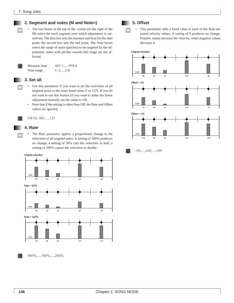
146 Chapter 2. SONG MODE
2. Segment and notes (M and Note=)• The two boxes at the top of the screen (to the right of the
M) select the track segment over which adjustment is car-ried out. The first box sets the measure and beat for the startpoint; the second box sets the end point. The Note boxesselect the range of notes (pitches) to be targeted by the ad-justment: notes with pitches outside this range are not af-fected.
01011101 Measure: beat 001:1,...,999:8
Note range C-2,...,G8
3. Set all• Use this parameter if you want to set the velocities of all
targeted notes to the same fixed value (1 to 127). If you donot want to use this feature (if you want to make the linearadjustment instead), set the value to Off.
• Note that if the setting is other than Off, the Rate and Offsetvalues are ignored.
01011101 Off (0), 001,...,127
4. Rate• The Rate parameter applies a proportional change to the
velocities of all targeted notes. A setting of 100% producesno change; a setting of 50% cuts the velocities in half; asetting of 200% causes the velocities to double.
01011101 000%,...,100%,...,200%
5. Offset• This parameter adds a fixed value to each of the Rate-ad-
justed velocity values. A setting of 0 produces no change.Positive values increase the velocity, while negative valuesdecrease it.
01011101 -99,...,+00,...,+99
7. Song Jobs
Original velocities
Rate = 50%
(Vel)
96 64 32 127 96
Rate = 150%
(Vel)
127 96 48 127 127
(Vel)
48 32 16 63 48
Original velocities
Offset = -20
(Vel)
96 64 32 127 96
Offset = +20
(Vel)
116 84 52 127 116
(Vel)
76 44 12 107 76
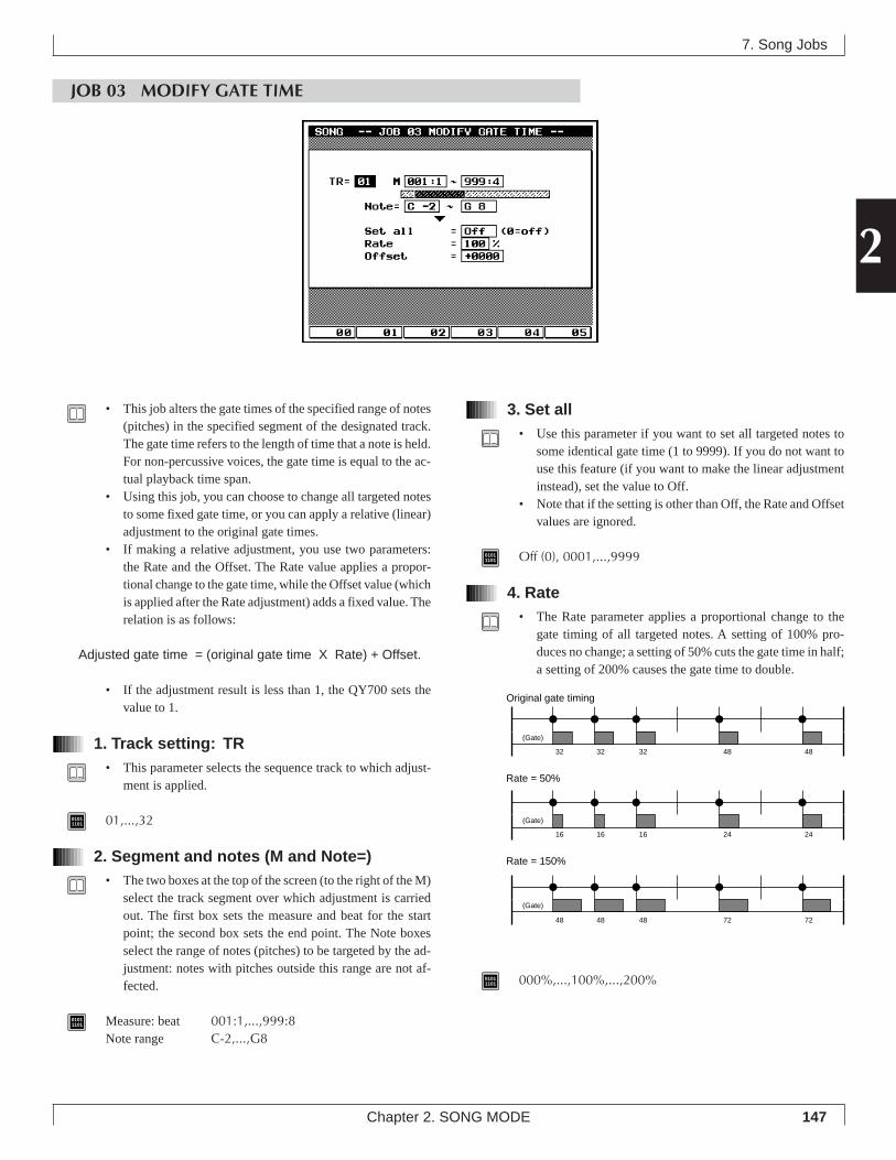
147
2
Chapter 2. SONG MODE
7. Song Jobs
JOB 03 MODIFY GATE TIME
3. Set all• Use this parameter if you want to set all targeted notes to
some identical gate time (1 to 9999). If you do not want touse this feature (if you want to make the linear adjustmentinstead), set the value to Off.
• Note that if the setting is other than Off, the Rate and Offsetvalues are ignored.
01011101 Off (0), 0001,...,9999
4. Rate• The Rate parameter applies a proportional change to the
gate timing of all targeted notes. A setting of 100% pro-duces no change; a setting of 50% cuts the gate time in half;a setting of 200% causes the gate time to double.
01011101 000%,...,100%,...,200%
• This job alters the gate times of the specified range of notes(pitches) in the specified segment of the designated track.The gate time refers to the length of time that a note is held.For non-percussive voices, the gate time is equal to the ac-tual playback time span.
• Using this job, you can choose to change all targeted notesto some fixed gate time, or you can apply a relative (linear)adjustment to the original gate times.
• If making a relative adjustment, you use two parameters:the Rate and the Offset. The Rate value applies a propor-tional change to the gate time, while the Offset value (whichis applied after the Rate adjustment) adds a fixed value. Therelation is as follows:
Adjusted gate time = (original gate time X Rate) + Offset.
• If the adjustment result is less than 1, the QY700 sets thevalue to 1.
1. Track setting: TR• This parameter selects the sequence track to which adjust-
ment is applied.
01011101 01,...,32
2. Segment and notes (M and Note=)• The two boxes at the top of the screen (to the right of the M)
select the track segment over which adjustment is carriedout. The first box sets the measure and beat for the startpoint; the second box sets the end point. The Note boxesselect the range of notes (pitches) to be targeted by the ad-justment: notes with pitches outside this range are not af-fected.
01011101 Measure: beat 001:1,...,999:8
Note range C-2,...,G8
Original gate timing
Rate = 50%
Rate = 150%
(Gate)
(Gate)
(Gate)
32 32 32 48 48
16 16 16 24 24
48 48 48 72 72
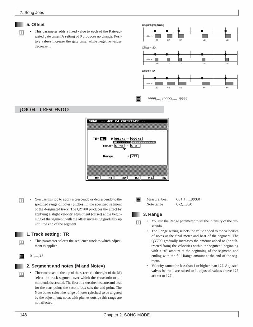
148 Chapter 2. SONG MODE
5. Offset• This parameter adds a fixed value to each of the Rate-ad-
justed gate times. A setting of 0 produces no change. Posi-tive values increase the gate time, while negative valuesdecrease it.
01011101 -9999,...,+0000,...,+9999
7. Song Jobs
JOB 04 CRESCENDO
• You use this job to apply a crescendo or decrescendo to thespecified range of notes (pitches) in the specified segmentof the designated track. The QY700 produces the effect byapplying a slight velocity adjustment (offset) at the begin-ning of the segment, with the offset increasing gradually upuntil the end of the segment.
1. Track setting: TR• This parameter selects the sequence track to which adjust-
ment is applied.
01011101 01,...,32
2. Segment and notes (M and Note=)• The two boxes at the top of the screen (to the right of the M)
select the track segment over which the crescendo or di-minuendo is created. The first box sets the measure and beatfor the start point; the second box sets the end point. TheNote boxes select the range of notes (pitches) to be targetedby the adjustment: notes with pitches outside this range arenot affected.
01011101 Measure: beat 001:1,...,999:8
Note range C-2,...,G8
3. Range• You use the Range parameter to set the intensity of the cre-
scendo.• The Range setting selects the value added to the velocities
of notes at the final meter and beat of the segment. TheQY700 gradually increases the amount added to (or sub-tracted from) the velocities within the segment, beginningwith a “0” amount at the beginning of the segment, andending with the full Range amount at the end of the seg-ment.
• Velocity cannot be less than 1 or higher than 127. Adjustedvalves below 1 are raised to 1, adjusted values above 127are set to 127.
Original gate timing
Offset = -20
Offset = +20
(Gate)
(Gate)
(Gate)
32 32 32 48 48
12 12 12 28 28
52 52 52 68 68
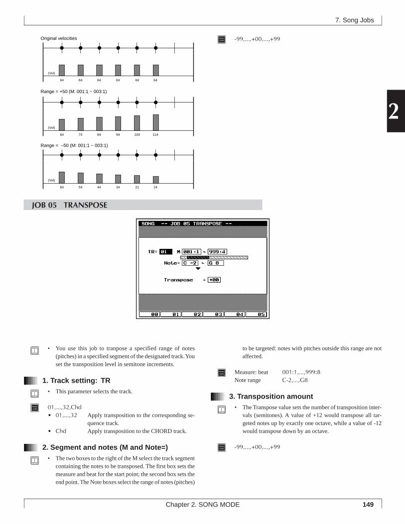
149
2
Chapter 2. SONG MODE
01011101 -99,...,+00,...,+99
7. Song Jobs
JOB 05 TRANSPOSE
• You use this job to tranpose a specified range of notes(pitches) in a specified segment of the designated track. Youset the transposition level in semitone increments.
1. Track setting: TR• This parameter selects the track.
01011101 01,...,32,Chd
• 01,...,32 Apply transposition to the corresponding se-quence track.
• Chd Apply transposition to the CHORD track.
2. Segment and notes (M and Note=)• The two boxes to the right of the M select the track segment
containing the notes to be transposed. The first box sets themeasure and beat for the start point; the second box sets theend point. The Note boxes select the range of notes (pitches)
to be targeted: notes with pitches outside this range are notaffected.
01011101 Measure: beat 001:1,...,999:8
Note range C-2,...,G8
3. Transposition amount• The Transpose value sets the number of transposition inter-
vals (semitones). A value of +12 would transpose all tar-geted notes up by exactly one octave, while a value of -12would transpose down by an octave.
01011101 -99,...,+00,...,+99
Original velocities
Range = +50 (M: 001:1 ~ 003:1)
(Vel)
64 64 64 64 6464
64 74 84 94 114104
64 54 44 34 1421
Range = –50 (M: 001:1 ~ 003:1)
(Vel)
(Vel)
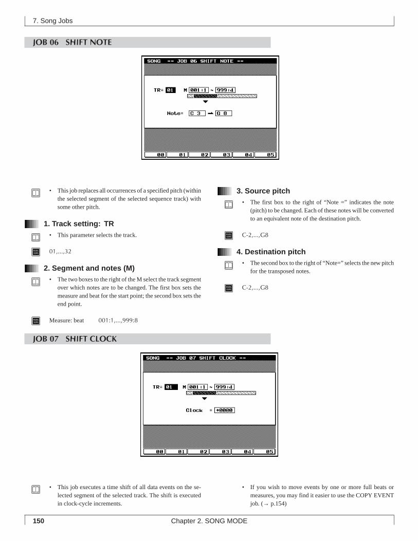
150 Chapter 2. SONG MODE
JOB 06 SHIFT NOTE
3. Source pitch• The first box to the right of “Note =” indicates the note
(pitch) to be changed. Each of these notes will be convertedto an equivalent note of the destination pitch.
01011101 C-2,...,G8
4. Destination pitch• The second box to the right of “Note=” selects the new pitch
for the transposed notes.
01011101 C-2,...,G8
7. Song Jobs
• This job replaces all occurrences of a specified pitch (withinthe selected segment of the selected sequence track) withsome other pitch.
1. Track setting: TR• This parameter selects the track.
01011101 01,...,32
2. Segment and notes (M)• The two boxes to the right of the M select the track segment
over which notes are to be changed. The first box sets themeasure and beat for the start point; the second box sets theend point.
01011101 Measure: beat 001:1,...,999:8
JOB 07 SHIFT CLOCK
• This job executes a time shift of all data events on the se-lected segment of the selected track. The shift is executedin clock-cycle increments.
• If you wish to move events by one or more full beats ormeasures, you may find it easier to use the COPY EVENTjob. (→ p.154)
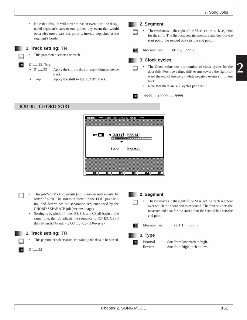
151
2
Chapter 2. SONG MODE
• Note that this job will never move an event past the desig-nated segment’s start or end points; any event that wouldotherwise move past this point is instead deposited at thesegment’s border.
1. Track setting: TR• This parameter selects the track.
01011101 01,...,32, Tmp
• 01,...,32 Apply the shift to the corresponding sequencetrack.
• Tmp Apply the shift to the TEMPO track.
2. Segment• The two boxes to the right of the M select the track segment
for the shift. The first box sets the measure and beat for thestart point; the second box sets the end point.
01011101 Measure: beat 001:1,...,999:8
3. Clock cycles• The Clock value sets the number of clock cycles for the
data shift. Positive values shift events toward the right (to-ward the end of the song), while negative events shift themback.
• Note that there are 480 cycles per beat.
01011101 -9999,...,+0000,...,+9999
7. Song Jobs
JOB 08 CHORD SORT
• This job “sorts” chord events (simultaneous note events) byorder of pitch. The sort is reflected in the EDIT page list-ing, and determines the separation sequence used by theCHORD SEPARATE job (see next page).
• Sorting is by pitch. If notes E3, C3, and G3 all begin at thesame time, the job adjusts the sequence to C3, E3, G3 (ifthe setting is Normal) to G3, E3, C3 (if Reverse).
1. Track setting: TR• This parameter selects track containing the data to be sorted.
01011101 01,...,32
2. Segment• The two boxes to the right of the M select the track segment
over which the chord sort is executed. The first box sets themeasure and beat for the start point; the second box sets theend point.
01011101 Measure: beat 001:1,...,999:8
3. Type01011101 Normal Sort from low pitch to high.
Reverse Sort from high pitch to low.
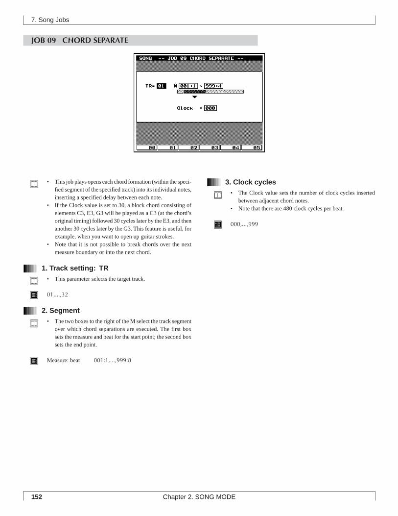
152 Chapter 2. SONG MODE
JOB 09 CHORD SEPARATE
7. Song Jobs
3. Clock cycles• The Clock value sets the number of clock cycles inserted
between adjacent chord notes.• Note that there are 480 clock cycles per beat.
01011101 000,...,999
• This job plays opens each chord formation (within the speci-fied segment of the specified track) into its individual notes,inserting a specified delay between each note.
• If the Clock value is set to 30, a block chord consisting ofelements C3, E3, G3 will be played as a C3 (at the chord’soriginal timing) followed 30 cycles later by the E3, and thenanother 30 cycles later by the G3. This feature is useful, forexample, when you want to open up guitar strokes.
• Note that it is not possible to break chords over the nextmeasure boundary or into the next chord.
1. Track setting: TR• This parameter selects the target track.
01011101 01,...,32
2. Segment• The two boxes to the right of the M select the track segment
over which chord separations are executed. The first boxsets the measure and beat for the start point; the second boxsets the end point.
01011101 Measure: beat 001:1,...,999:8
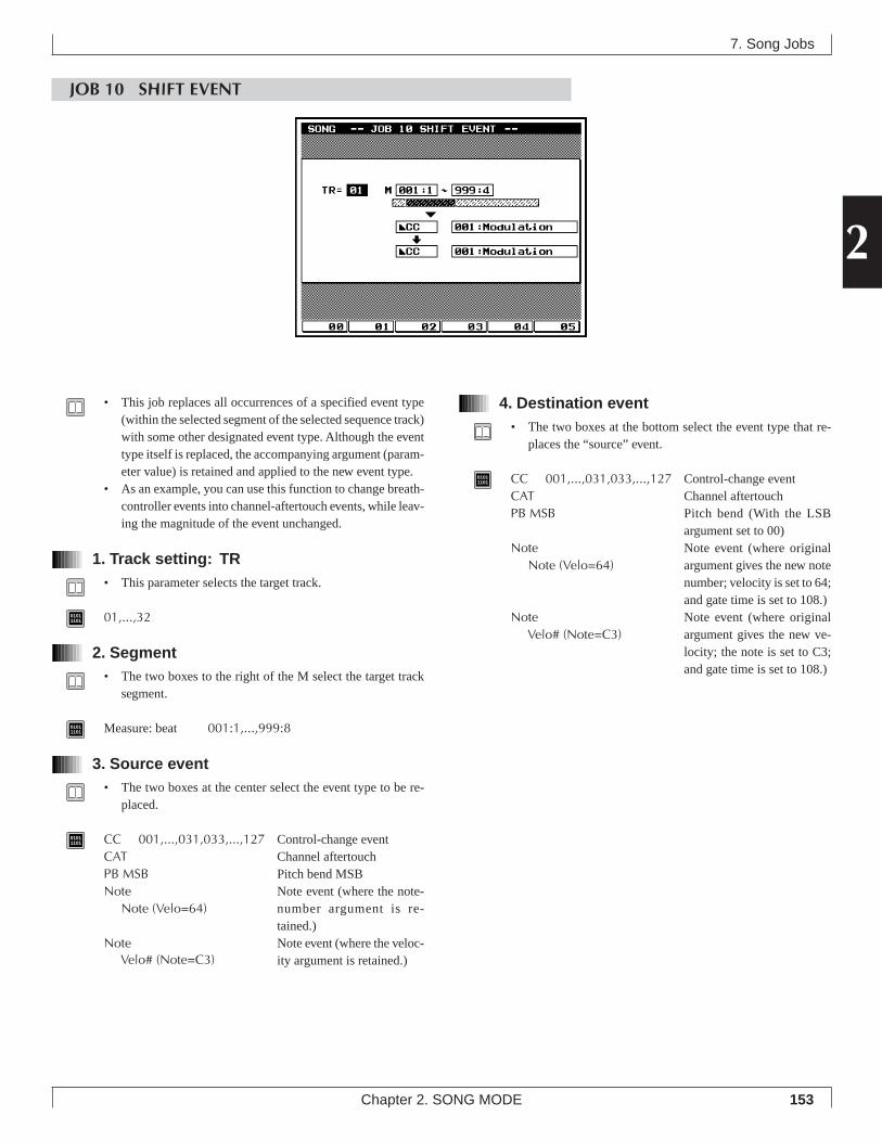
153
2
Chapter 2. SONG MODE
7. Song Jobs
JOB 10 SHIFT EVENT
4. Destination event• The two boxes at the bottom select the event type that re-
places the “source” event.
01011101 CC 001,...,031,033,...,127 Control-change event
CAT Channel aftertouchPB MSB Pitch bend (With the LSB
argument set to 00)Note Note event (where original
argument gives the new notenumber; velocity is set to 64;and gate time is set to 108.)
Note Note event (where originalargument gives the new ve-locity; the note is set to C3;and gate time is set to 108.)
• This job replaces all occurrences of a specified event type(within the selected segment of the selected sequence track)with some other designated event type. Although the eventtype itself is replaced, the accompanying argument (param-eter value) is retained and applied to the new event type.
• As an example, you can use this function to change breath-controller events into channel-aftertouch events, while leav-ing the magnitude of the event unchanged.
1. Track setting: TR• This parameter selects the target track.
01011101 01,...,32
2. Segment• The two boxes to the right of the M select the target track
segment.
01011101 Measure: beat 001:1,...,999:8
3. Source event• The two boxes at the center select the event type to be re-
placed.
01011101 CC 001,...,031,033,...,127 Control-change event
CAT Channel aftertouchPB MSB Pitch bend MSBNote Note event (where the note-
number argument is re-tained.)
Note Note event (where the veloc-ity argument is retained.)
Note (Velo=64)
Note (Velo=64)
Velo# (Note=C3)
Velo# (Note=C3)
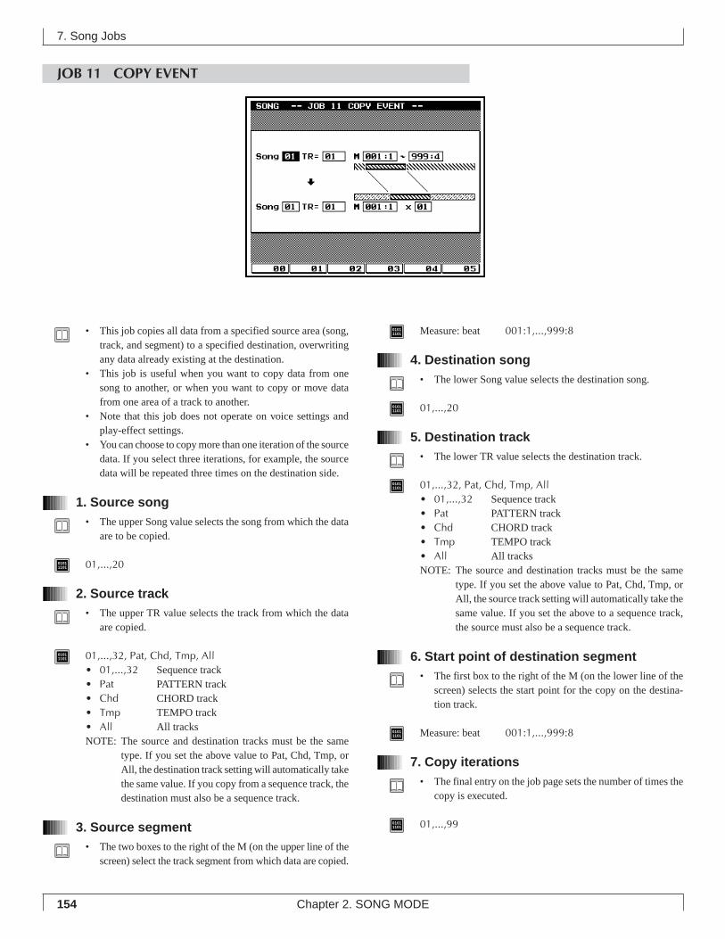
154 Chapter 2. SONG MODE
JOB 11 COPY EVENT
7. Song Jobs
01011101 Measure: beat 001:1,...,999:8
4. Destination song• The lower Song value selects the destination song.
01011101 01,...,20
5. Destination track• The lower TR value selects the destination track.
01011101 01,...,32, Pat, Chd, Tmp, All
• 01,...,32 Sequence track• Pat PATTERN track• Chd CHORD track• Tmp TEMPO track• All All tracksNOTE: The source and destination tracks must be the same
type. If you set the above value to Pat, Chd, Tmp, orAll, the source track setting will automatically take thesame value. If you set the above to a sequence track,the source must also be a sequence track.
6. Start point of destination segment• The first box to the right of the M (on the lower line of the
screen) selects the start point for the copy on the destina-tion track.
01011101 Measure: beat 001:1,...,999:8
7. Copy iterations• The final entry on the job page sets the number of times the
copy is executed.
01011101 01,...,99
• This job copies all data from a specified source area (song,track, and segment) to a specified destination, overwritingany data already existing at the destination.
• This job is useful when you want to copy data from onesong to another, or when you want to copy or move datafrom one area of a track to another.
• Note that this job does not operate on voice settings andplay-effect settings.
• You can choose to copy more than one iteration of the sourcedata. If you select three iterations, for example, the sourcedata will be repeated three times on the destination side.
1. Source song• The upper Song value selects the song from which the data
are to be copied.
01011101 01,...,20
2. Source track• The upper TR value selects the track from which the data
are copied.
01011101 01,...,32, Pat, Chd, Tmp, All
• 01,...,32 Sequence track• Pat PATTERN track• Chd CHORD track• Tmp TEMPO track• All All tracksNOTE: The source and destination tracks must be the same
type. If you set the above value to Pat, Chd, Tmp, orAll, the destination track setting will automatically takethe same value. If you copy from a sequence track, thedestination must also be a sequence track.
3. Source segment• The two boxes to the right of the M (on the upper line of the
screen) select the track segment from which data are copied.
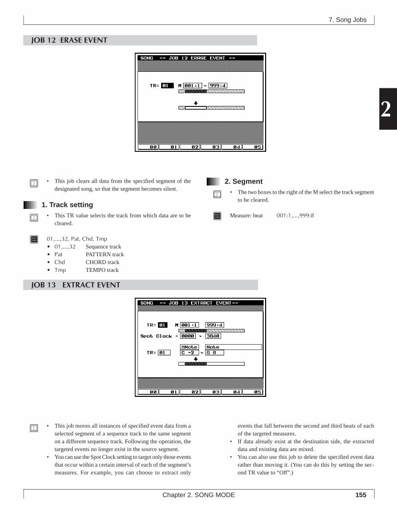
155
2
Chapter 2. SONG MODE
7. Song Jobs
JOB 12 ERASE EVENT
2. Segment• The two boxes to the right of the M select the track segment
to be cleared.
01011101 Measure: beat 001:1,...,999:8
• This job clears all data from the specified segment of thedesignated song, so that the segment becomes silent.
1. Track setting• This TR value selects the track from which data are to be
cleared.
01011101 01,...,32, Pat, Chd, Tmp
• 01,...,32 Sequence track• Pat PATTERN track• Chd CHORD track• Tmp TEMPO track
JOB 13 EXTRACT EVENT
• This job moves all instances of specified event data from aselected segment of a sequence track to the same segmenton a different sequence track. Following the operation, thetargeted events no longer exist in the source segment.
• You can use the Spot Clock setting to target only those eventsthat occur within a certain interval of each of the segment’smeasures. For example, you can choose to extract only
events that fall between the second and third beats of eachof the targeted measures.
• If data already exist at the destination side, the extracteddata and existing data are mixed.
• You can also use this job to delete the specified event datarather than moving it. (You can do this by setting the sec-ond TR value to “Off”.)
156 Chapter 2. SONG MODE
1. Source track• The first TR setting selects the track from which events are
to be extracted.
01011101 01,...,32
2. Source segment• The two boxes to the right of the M select the track segment
for the extraction.
01011101 Measure: beat 001:1,...,999:8
3. Spot clock• The Spot Clock parameter selects the interval of each meas-
ure from which data are to be extracted.• The interval is set by clock cycles, where each measure starts
at cycle 0000. There are 480 cycles per quarter note.• For example, assume that timing is set to 4/4. In this
case, if you want to extract data only from the first halfof each measure, you would set the range to 0000 – 0959.If you wanted to copy only those events that fall exactlyon the fourth beat, you would set the range to 1440 –1440.
01011101 0000,...,3840
4. Destination track• The lower TR setting selects the destination track.
01011101 01,...,32, Off
• 01,...,32 Sequence track• Off No destination. (Extract and delete)
5. Event• The third pair of boxes (at the center of the screen) select
the event type to be extracted.
01011101 Note, PC, PB, CC (000,...,127, All), CAT, PAT, EXC
• Note Note events (C2,...,G8, All)• PC Program change• PB Pitch bend• CC(000,...,127,All) Control change (Any single control-
change message type 000 to 127, orall control-change messages)
• CAT Channel aftertouch• PAT Polyphonic aftertouch• EXC System exclusive
6. Argument range• The lowest two boxes on the screen select the argument
range. The QY700 will extract only those note events whosearguments fall within the specified range.
• If you are extracting note events, for example, you can usethis setting to limit extraction to all note events within acertain pitch range (for example, C3 to C4). If extractingprogram-change events, you can limit extraction to eventswith a certain range of program numbers only.
• Note that the EXC event type does not accept an argument-range value.
• The values listed below show the maximum ranges. In allcases you can set a smaller range. Note that the first valueof the range must be less than or equal to the second value.
01011101 C-2,...,G8 Maximum range for note events
-8192,...,+8191 Maximum range for pitchbend events000,..,127 Maximum range for all event types other than
note and pitchbend.
7. Song Jobs
0000 0480 0960 1440 19194/4
0000 04800240 09600720 1200 14396/8
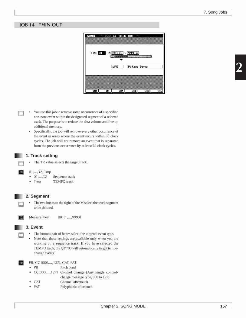
157
2
Chapter 2. SONG MODE
JOB 14 THIN OUT
7. Song Jobs
• You use this job to remove some occurrences of a specifiednon-note event within the designated segment of a selectedtrack. The purpose is to reduce the data volume and free upadditional memory.
• Specifically, the job will remove every other occurrence ofthe event in areas where the event recurs within 60 clockcycles. The job will not remove an event that is separatedfrom the previous occurrence by at least 60 clock cycles.
1. Track setting• The TR value selects the target track.
01011101 01,...,32, Tmp
• 01,...,32 Sequence track• Tmp TEMPO track
2. Segment• The two boxes to the right of the M select the track segment
to be thinned.
01011101 Measure: beat 001:1,...,999:8
3. Event• The bottom pair of boxes select the targeted event type.• Note that these settings are available only when you are
working on a sequence track. If you have selected theTEMPO track, the QY700 will automatically target tempo-change events.
01011101 PB, CC (000,...,127), CAT, PAT
• PB Pitch bend• CC(000,...,127) Control change (Any single control-
change message type, 000 to 127)• CAT Channel aftertouch• PAT Polyphonic aftertouch
158 Chapter 2. SONG MODE
7. Song Jobs
JOB 15 TIME STRETCH
2. Segment• The two boxes to the right of the M select the target seg-
ment of the track.
01011101 Measure: beat 001:1,...,999:8
3. Time• The Time parameter sets the time multiplier.
01011101 050%,...,200%
• This job expands or compresses the timing over the selectedsegment on the selected track.
• The operation affects all event timing, note step times, andnote gate times.
1. Track setting• The TR value selects the target track.
01011101 01,...,32, All
• 01,...,32 Corresponding sequence track• All All sequence tracks
JOB 16 CREATE MEASURE
• This job inserts one or more empty measures into the samelocation on all tracks (all 32 sequence tracks, as well as thePATTERN, CHORD, and TEMPO tracks).
1. Insertion point• The M value sets the position for the insertion. Specifically,
the value sets the measure number (within the song) for thefirst inserted measure. A value of 001, for example, insertsthe measures at the very beginning (so that the first insertedmeasure becomes Measure 1).
159
2
Chapter 2. SONG MODE
01011101 001,...,999
• If you set the insertion point past the end of the song, theQY700 will append the empty measure(s) to the end of Track1 only.
2. Meter• The middle box on the screen sets the meter for the new
measure.• You can select any meter that you like. You may find it con-
venient to use this job when you need to create a song thatincorporates meter changes.
01011101 1/16,...,16/16; 1/8,...,16/8; 1/4,...,8/4
3. Number of measures to insert• The final box on the screen sets the number of measures to
be inserted.
01011101 01,...,99
7. Song Jobs
JOB 17 DELETE MEASURE
• This job removes a segment consisting of one or more meas-ures. The segment is removed from all tracks (all 32 se-quence tracks, as well as the PATTERN, CHORD, andTEMPO tracks).
• The area that trails the deleted segment shifts forward (to-ward the start of the song) to fill in the gap.
1. Range• The M values set the segment to be removed. The first value
gives the number of the first measure of the segment; thesecond value gives the number of the final measure.
01011101 001,...,999
160 Chapter 2. SONG MODE
JOB 18 COPY TRACK
7. Song Jobs
4. Destination track• The second TR setting selects the destination track.
01011101 01,...,32, Pat, Chd, Tmp
• 01,...,32 Sequence track• Pat PATTERN track• Chd CHORD track• Tmp TEMPO trackNOTE: The source and destination tracks must be the same
type. If you set the destination to Pat, Chd, or Tmp, thesource track setting will automatically take the samevalue. If you copy from a sequence track, the destina-tion must also be a sequence track.
5. Data type• The last three items on the screen allow you to select the
type of data to be targeted. You can select one or more ofthese types by placing checkmarks into the correspondingboxes.• If you select Event, the job copies all event data from
the source track to the destination track.• If you select Play Effect, the job copies all of the source
track’s SONG-mode play effect settings.• If you select Voice, the job copies all of the source track’s
associated VOICE-mode settings.• The checkmark settings have no meaning if the track is set
to Pat, Chd, or Tmp.
01011101 Copy the corresponding data type.
Do not copy this data type.
• This job copies all data (or a selected type of data; see be-low) from one track onto another. The source and destina-tion tracks may be in the same song, or in different songs.
• Note that the source track’s transmission-channel and me-ter settings are not copied.
• This operation overwrites any data already existing on thedestination track.
1. Source song• The first Song setting selects the song containing the source
track.
01011101 01,...,20
2. Source track• The first TR setting selects the track containing the data to
be copied.
01011101 01,...,32, Pat, Chd, Tmp
• 01,...,32 Sequence track• Pat PATTERN track• Chd CHORD track• Tmp TEMPO trackNOTE: The source and destination tracks must be the same
type. If you set the above value to Pat, Chd, or Tmp,the destination track setting will automatically take thesame value. If you copy from a sequence track, thedestination must also be a sequence track.
3. Destination song• The second Song setting selects the song containing the des-
tination track.
01011101 01,...,20
161
2
Chapter 2. SONG MODE
7. Song Jobs
JOB 19 MIX TRACKS
5. Play Effect and Voice source• The final two items let you select which play-effect and
voice settings to apply to the destination track (track “b”).For both Play Effect and Voice, you can choose to apply thevalues from track “a” or to retain the values already in ef-fect at track “b”.
01011101 a, b
• a Use the settings from track “a”.• b Use the settings from track “b”.
• This job mixes all data from a selected sequence track ontoanother sequence track. The two tracks do not have to be inthe same song.
• When the operation is completed, the source track remainsunchanged, while the destination track contains both itsoriginal data and a copy of the source track’s data.
1. Source song• The first Song value selects the song containing the source
track.
01011101 01,...,20
2. Source track (Track “a”)• The first TR value selects the source track. This is the track
containing the data to be mixed into the destination track.Following the mix, the source track’s content will remainunchanged.
01011101 01,...,32
3. Destination song• The second Song value selects the song containing the des-
tination track (track “b”).
01011101 01,...,20
4. Destination track (Track “b”)• The second TR value selects the destination track. The origi-
nal content of this track becomes mixed with the contentfrom Track “a.”
01011101 01,...,32
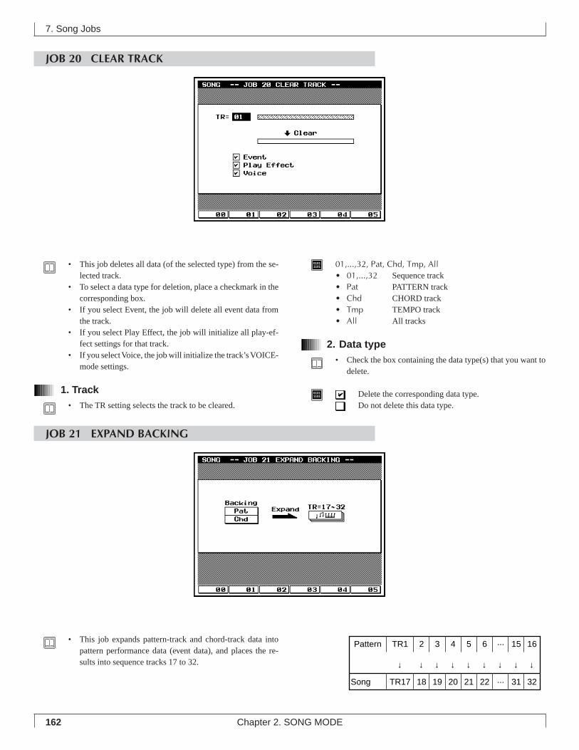
162 Chapter 2. SONG MODE
7. Song Jobs
JOB 20 CLEAR TRACK
01011101 01,...,32, Pat, Chd, Tmp, All
• 01,...,32 Sequence track• Pat PATTERN track• Chd CHORD track• Tmp TEMPO track• All All tracks
2. Data type• Check the box containing the data type(s) that you want to
delete.
01011101 Delete the corresponding data type.
Do not delete this data type.
• This job deletes all data (of the selected type) from the se-lected track.
• To select a data type for deletion, place a checkmark in thecorresponding box.
• If you select Event, the job will delete all event data fromthe track.
• If you select Play Effect, the job will initialize all play-ef-fect settings for that track.
• If you select Voice, the job will initialize the track’s VOICE-mode settings.
1. Track• The TR setting selects the track to be cleared.
JOB 21 EXPAND BACKING
• This job expands pattern-track and chord-track data intopattern performance data (event data), and places the re-sults into sequence tracks 17 to 32.
Pattern TR1 2 3 4 5 6 ··· 15 16 ↓ ↓ ↓ ↓ ↓ ↓ ↓ ↓ ↓
Song TR17 18 19 20 21 22 ··· 31 32
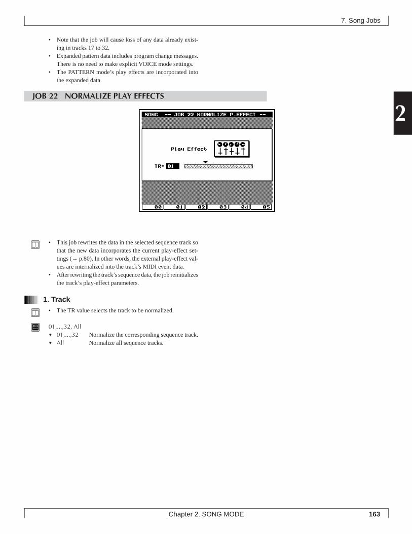
163
2
Chapter 2. SONG MODE
7. Song Jobs
• Note that the job will cause loss of any data already exist-ing in tracks 17 to 32.
• Expanded pattern data includes program change messages.There is no need to make explicit VOICE mode settings.
• The PATTERN mode’s play effects are incorporated intothe expanded data.
JOB 22 NORMALIZE PLAY EFFECTS
• This job rewrites the data in the selected sequence track sothat the new data incorporates the current play-effect set-tings (→ p.80). In other words, the external play-effect val-ues are internalized into the track’s MIDI event data.
• After rewriting the track’s sequence data, the job reinitializesthe track’s play-effect parameters.
1. Track• The TR value selects the track to be normalized.
01011101 01,...,32, All
• 01,...,32 Normalize the corresponding sequence track.• All Normalize all sequence tracks.
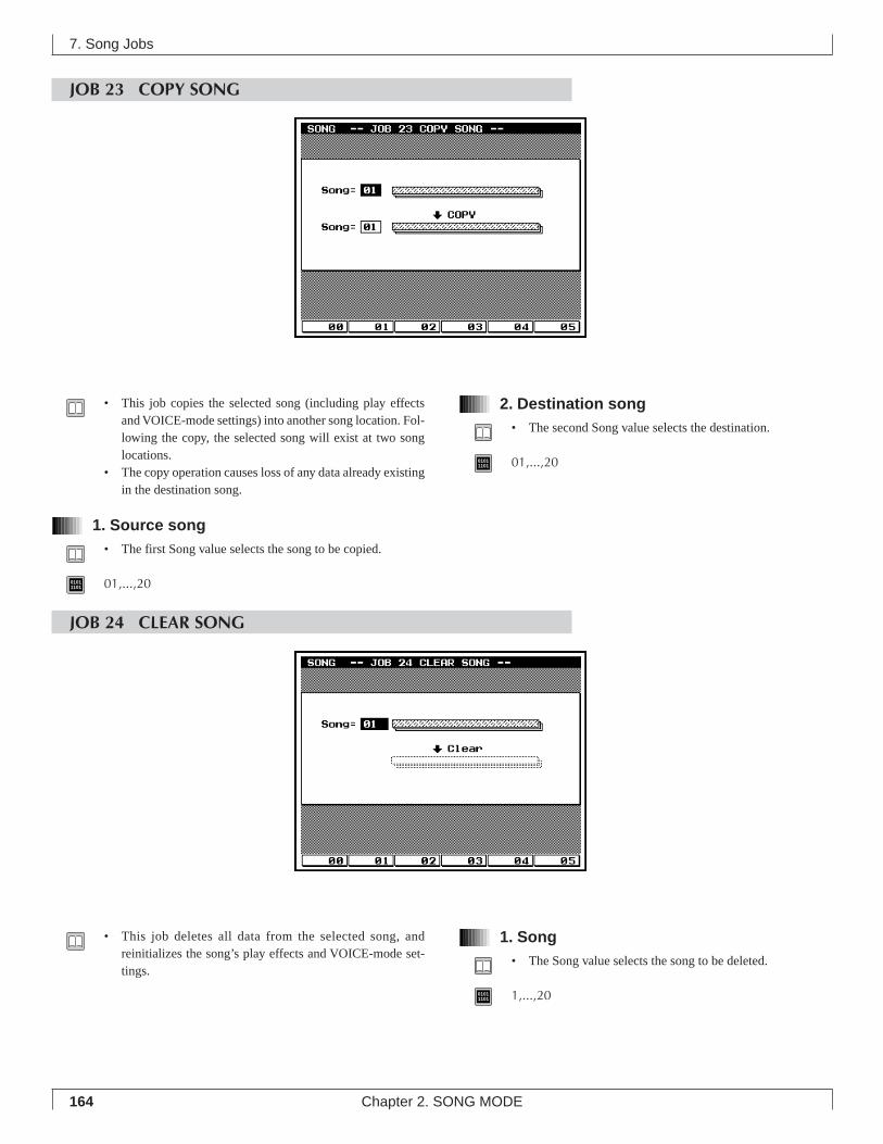
164 Chapter 2. SONG MODE
7. Song Jobs
JOB 23 COPY SONG
• This job copies the selected song (including play effectsand VOICE-mode settings) into another song location. Fol-lowing the copy, the selected song will exist at two songlocations.
• The copy operation causes loss of any data already existingin the destination song.
1. Source song• The first Song value selects the song to be copied.
01011101 01,...,20
2. Destination song• The second Song value selects the destination.
01011101 01,...,20
JOB 24 CLEAR SONG
• This job deletes all data from the selected song, andreinitializes the song’s play effects and VOICE-mode set-tings.
1. Song• The Song value selects the song to be deleted.
01011101 1,...,20
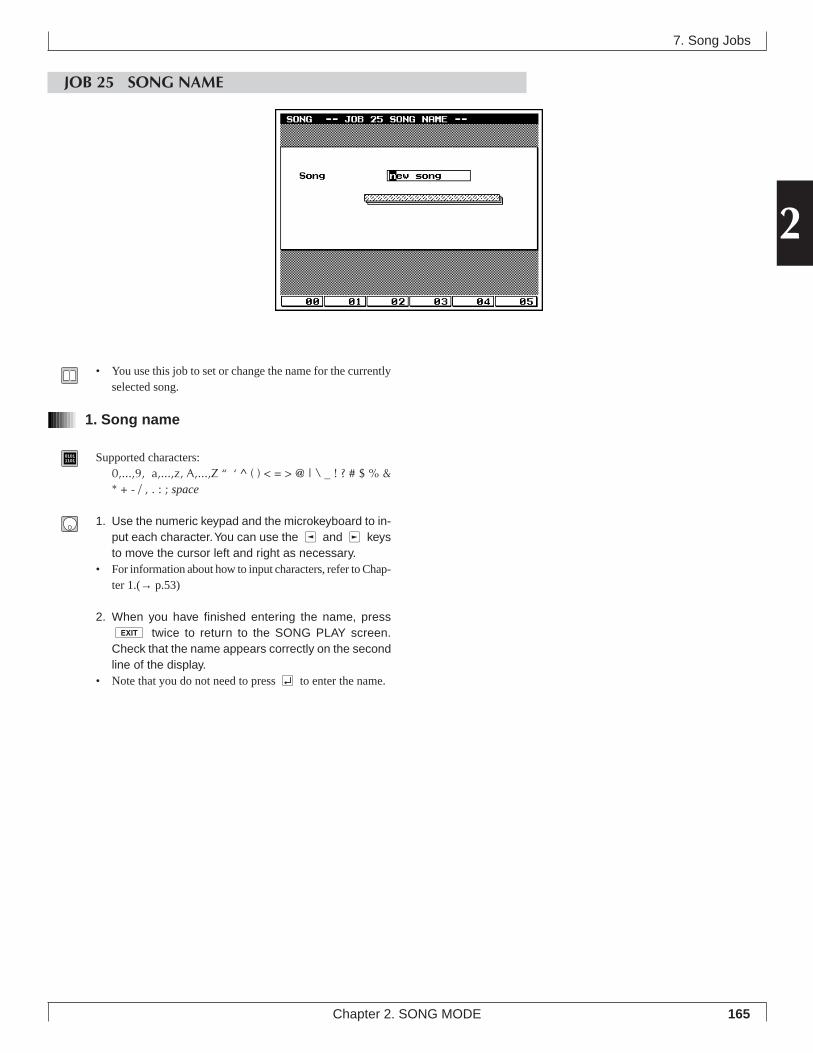
165
2
Chapter 2. SONG MODE
7. Song Jobs
JOB 25 SONG NAME
• You use this job to set or change the name for the currentlyselected song.
1. Song name
01011101 Supported characters:
0,...,9, a,...,z, A,...,Z “ ‘ ^ ( ) < = > @ | \ _ ! ? # $ % &* + - / , . : ; space
1. Use the numeric keypad and the microkeyboard to in-put each character. You can use the l and r keysto move the cursor left and right as necessary.
• For information about how to input characters, refer to Chap-ter 1.(→ p.53)
2. When you have finished entering the name, presse twice to return to the SONG PLAY screen.Check that the name appears correctly on the secondline of the display.
• Note that you do not need to press e to enter the name.
166 Chapter 2. SONG MODE
7. Song Jobs
Memo
Chapter 3. VOICE MODE
3
About Voice mode ........................................ 1681. Mixer ......................................................... 1702. Tune .......................................................... 1743. Voice Edit .................................................. 1764. Drum Setup Edit ....................................... 182
This chapter explains mixer, tune, and voice edit settings.
Voice mode is where you will select the voices used by a song, and
edit voices.
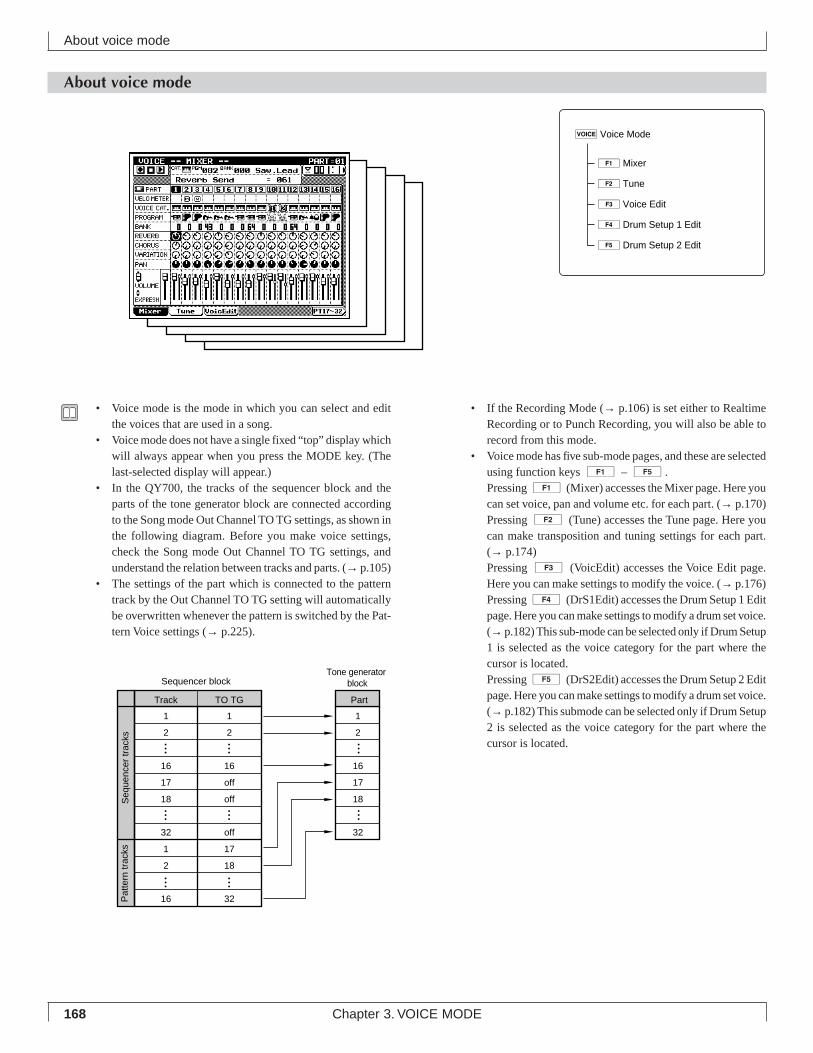
168 Chapter 3. VOICE MODE
• If the Recording Mode (→ p.106) is set either to RealtimeRecording or to Punch Recording, you will also be able torecord from this mode.
• Voice mode has five sub-mode pages, and these are selectedusing function keys 1 – 5.Pressing 1 (Mixer) accesses the Mixer page. Here youcan set voice, pan and volume etc. for each part. (→ p.170)Pressing 2 (Tune) accesses the Tune page. Here youcan make transposition and tuning settings for each part.(→ p.174)Pressing 3 (VoicEdit) accesses the Voice Edit page.Here you can make settings to modify the voice. (→ p.176)Pressing 4 (DrS1Edit) accesses the Drum Setup 1 Editpage. Here you can make settings to modify a drum set voice.(→ p.182) This sub-mode can be selected only if Drum Setup1 is selected as the voice category for the part where thecursor is located.Pressing 5 (DrS2Edit) accesses the Drum Setup 2 Editpage. Here you can make settings to modify a drum set voice.(→ p.182) This submode can be selected only if Drum Setup2 is selected as the voice category for the part where thecursor is located.
About voice mode
• Voice mode is the mode in which you can select and editthe voices that are used in a song.
• Voice mode does not have a single fixed “top” display whichwill always appear when you press the MODE key. (Thelast-selected display will appear.)
• In the QY700, the tracks of the sequencer block and theparts of the tone generator block are connected accordingto the Song mode Out Channel TO TG settings, as shown inthe following diagram. Before you make voice settings,check the Song mode Out Channel TO TG settings, andunderstand the relation between tracks and parts. (→ p.105)
• The settings of the part which is connected to the patterntrack by the Out Channel TO TG setting will automaticallybe overwritten whenever the pattern is switched by the Pat-tern Voice settings (→ p.225).
About voice mode
1Mixer
2Tune
3Voice Edit
4Drum Setup 1 Edit
5Drum Setup 2 Edit
vVoice Mode
Track TO TG
1 1
2 2
16 16
17 off
18 off
32 off
1 17
2 18
16 32
1
2
16
17
18
32
Part
Sequencer blockTone generator
block
Seq
uenc
er tr
acks
Pat
tern
trac
ks
169
3
Chapter 3. VOICE MODE
• If the song contains “GM Mode On”, “XG System On”, orcontrol change or exclusive messages which set programchanges, the settings of Voice mode will be ignored.
• If you want your Voice mode settings to be reflected in thedata, highlight the XG Header item in the Save page of Diskmode when saving the song to a Standard MIDI File etc.(→ p.307)
About voice mode
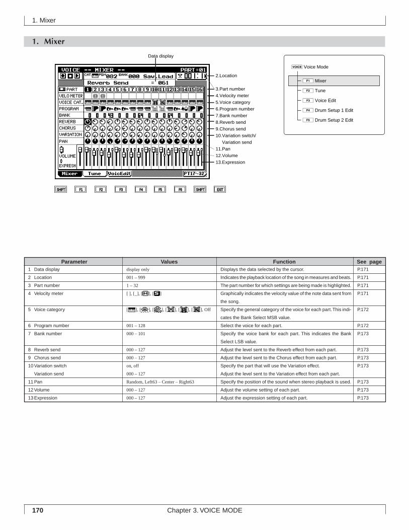
170 Chapter 3. VOICE MODE
1. Mixer
1. Mixer
Data display
2.Location
3.Part number
4.Velocity meter
5.Voice category
6.Program number
7.Bank number
8.Reverb send
9.Chorus send
10.Variation switch/
Variation send
11.Pan
12.Volume
13.Expression
SHIFT F1 F2 F3 F4 F5 F6 SHIFT EXIT
Displays the data selected by the cursor.
Indicates the playback location of the song in measures and beats.
The part number for which settings are being made is highlighted.
Graphically indicates the velocity value of the note data sent from
the song.
Specify the general category of the voice for each part. This indi-
cates the Bank Select MSB value.
Select the voice for each part.
Specify the voice bank for each part. This indicates the Bank
Select LSB value.
Adjust the level sent to the Reverb effect from each part.
Adjust the level sent to the Chorus effect from each part.
Specify the part that will use the Variation effect.
Adjust the level sent to the Variation effect from each part.
Specify the position of the sound when stereo playback is used.
Adjust the volume setting of each part.
Adjust the expression setting of each part.
display only
001 – 999
1 – 32
[ ], [_], [ ], [ ]
[ ], [ ], [ ], [ ], [ ], [ ], Off
001 – 128
000 – 101
000 – 127
000 – 127
on, off
000 – 127
Random, Left63 – Center – Right63
000 – 127
000 – 127
Parameter Values Function See pageP.171
P.171
P.171
P.171
P.172
P.172
P.173
P.173
P.173
P.173
P.173
P.173
P.173
1 Data display
2 Location
3 Part number
4 Velocity meter
5 Voice category
6 Program number
7 Bank number
8 Reverb send
9 Chorus send
10 Variation switch
Variation send
11 Pan
12 Volume
13 Expression
2Tune
3Voice Edit
4Drum Setup 1 Edit
5Drum Setup 2 Edit
vVoice Mode
1Mixer
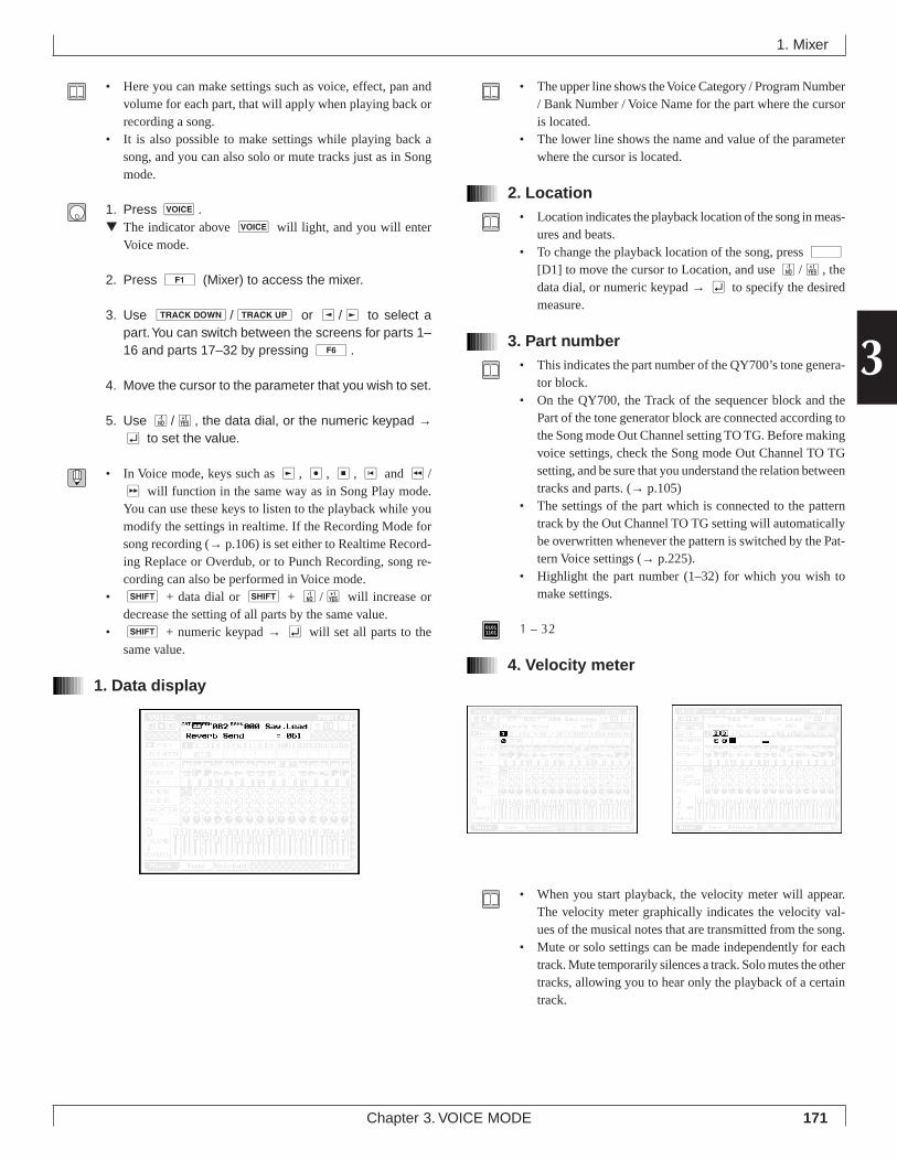
171
3
Chapter 3. VOICE MODE
• Here you can make settings such as voice, effect, pan andvolume for each part, that will apply when playing back orrecording a song.
• It is also possible to make settings while playing back asong, and you can also solo or mute tracks just as in Songmode.
1. Press v.▼ The indicator above v will light, and you will enter
Voice mode.
2. Press 1 (Mixer) to access the mixer.
3. Use d/u or l/r to select apart. You can switch between the screens for parts 1–16 and parts 17–32 by pressing 6.
4. Move the cursor to the parameter that you wish to set.
5. Use n/y, the data dial, or the numeric keypad →e to set the value.
• In Voice mode, keys such as r, e, s, t and r/f will function in the same way as in Song Play mode.You can use these keys to listen to the playback while youmodify the settings in realtime. If the Recording Mode forsong recording (→ p.106) is set either to Realtime Record-ing Replace or Overdub, or to Punch Recording, song re-cording can also be performed in Voice mode.
• s + data dial or s + n/y will increase ordecrease the setting of all parts by the same value.
• s + numeric keypad → e will set all parts to thesame value.
1. Data display
• The upper line shows the Voice Category / Program Number/ Bank Number / Voice Name for the part where the cursoris located.
• The lower line shows the name and value of the parameterwhere the cursor is located.
2. Location• Location indicates the playback location of the song in meas-
ures and beats.• To change the playback location of the song, press d
[D1] to move the cursor to Location, and use n/y, thedata dial, or numeric keypad → e to specify the desiredmeasure.
3. Part number• This indicates the part number of the QY700’s tone genera-
tor block.• On the QY700, the Track of the sequencer block and the
Part of the tone generator block are connected according tothe Song mode Out Channel setting TO TG. Before makingvoice settings, check the Song mode Out Channel TO TGsetting, and be sure that you understand the relation betweentracks and parts. (→ p.105)
• The settings of the part which is connected to the patterntrack by the Out Channel TO TG setting will automaticallybe overwritten whenever the pattern is switched by the Pat-tern Voice settings (→ p.225).
• Highlight the part number (1–32) for which you wish tomake settings.
01011101 1 – 32
4. Velocity meter
• When you start playback, the velocity meter will appear.The velocity meter graphically indicates the velocity val-ues of the musical notes that are transmitted from the song.
• Mute or solo settings can be made independently for eachtrack. Mute temporarily silences a track. Solo mutes the othertracks, allowing you to hear only the playback of a certaintrack.
1. Mixer

172 Chapter 3. VOICE MODE
1. Use d/u or the cursor keys tomove the cursor to the desired track.
2. Press m, and the display will indicate and thetrack will be muted.If you press m once again for a muted track, it will beun-muted.
3. Press s, and the display will indicate and allother tracks will be displayed as dashed lines, and onlythe sound of the track located at the cursor will beheard.When a track is being soloed, moving the cursor to anothertrack and pressing s will switch the soloed track. Inthis way, you can successively audition the playback of eachtrack.When a track is being soloed, moving the cursor to anothertrack and pressing s + s will add the selectedtrack to the playback, allowing you to solo two or moretracks.
4. When you press s on a soloed track, all solo set-tings will be canceled simultaneously.When you press s + s on a soloed track, solowill be canceled only for that track.
5. Voice category
• Voice Category allows you to change the Bank Select MSBvalue to specify the general category of the voice.
• Normal Voice is the voice category that specifies normalvoices (instrumental sounds). Specify a Bank Select MSBof 000.
• SFX Voice is a voice category that specifies sound effects.Sounds effects in this category change their pitch whenplayed from different notes of the keyboard. Specify a BankSelect MSB of 064.
• SFX Kit is a voice category that specifies sound effects.Sounds effects in this category produce a different type ofsound effect for each note of the keyboard, similarly to adrum voice. Specify a Bank Select MSB of 126.
• Drum Voice is the voice category that specifies drum voices.In this category, you can specify Drum Voice for two ormore parts, and select a different drum set voice for eachpart. However it is not possible to modify the drum sounds.Specify a Bank Select MSB of 127.
• Drum S1 and Drum S2 are voice categories that specifyDrum Setups. The drum voices in this category can be modi-fied using Drum Setup Edit. However if Drum S1 is speci-fied for two or more parts, selecting a drum set voice ormodifying the sound for one of the parts will automaticallychange the settings for the other parts as well.
01011101 Normal Voice
SFX VoiceSFX KitDrum VoiceDrum Setup 1Drum Setup 2
Off Part off
6. Program number• Program Number specifies the voice number that will be
used by each part.• Voices are selected by three values: Voice Category, Bank
Number (see following item) and Program Number.• A voice icon will be displayed at the cursor location. The
data display location will show the specified programnumber and the name of the selected voice.
• The available program numbers will depend on the VoiceCategory.
• During playback, this setting will change according to theProgram Change data that was recorded into each track ofthe sequencer block.
01011101 001–128
• For details on voice selection, refer to “Chapter 1. BASICCONCEPTS”. (→ p.43)
• For voice names and numbers, refer to the separate “QY700Reference Listings”.
1. Mixer
173
3
Chapter 3. VOICE MODE
7. Bank number• Bank Number specifies the Bank Select LSB of the voice
that will be used by each part.• Voices are selected by three values: Voice Category, Bank
Number and Program Number.• If the Voice Category is other than (Normal Voice), the
Bank Number will be fixed at 000.
01011101 000–101 (discontinuous)
• For details on bank selection, refer to “Chapter 1. BASICCONCEPTS”. (→ p.43)
• For bank numbers, refer to the separate “QY700 ReferenceListings”.
8. Reverb send• This specifies the amount that will be sent from each part to
the Reverb effect, adjusting the reverb depth.• When making this setting, take into consideration the Ef-
fect mode Reverb Return setting (→ p.191).
01011101 000–127
9. Chorus send• This specifies the amount that will be sent from each part to
the Chorus effect, adjusting the chorus depth.• When making this setting, take into consideration the Ef-
fect mode Chorus Return setting (→ p.192).
01011101 000–127
10. Variation switch / Variation send• If the Effect mode Variation Mode (→ p.190) is set to Inser-
tion, this setting functions as the Variation Switch, specify-ing the part which will use the Variation effect.Only one selected part can be turned on.
• If the Effect mode Variation Mode (→ p.190) is set to Sys-tem, this setting functions as the Variation Send Level, set-ting the amount that will be sent from each part to the Vari-ation effect, and thus adjusting the depth of the effect.
• When making this setting, take into consideration the Ef-fect mode Variation Return setting.
01011101 • Variation Switch
Off, On (Insertion)• Variation Send Level
000–127 (System)
11. Pan• This sets the pan position (stereo location) for stereo play-
back.• During playback, this value will follow the Pan data con-
tained in the track.• If a Drum Voice is selected, the pan setting specified here
will function as an offset relative to the pan setting speci-fied for each drum instrument.
• Settings of Left63–Center–Right63 will place the sound to-ward the left, in the center, or toward the right.
• A setting of Random will produce a special effect in whichthe sound be move between left and right randomly for eachnote.
01011101 Random (0), Left63(1)–Center(64)–Right63(127)
12. Volume• This sets the volume for each part.• The slider located at the left edge of the display is the mas-
ter volume.• During playback, this value will follow the Volume data
contained in the track.
01011101 000–127
13. Expression• This sets the expression level for each part.• During playback, this value will follow the Expression data
contained in the track.
01011101 000–127
1. Mixer
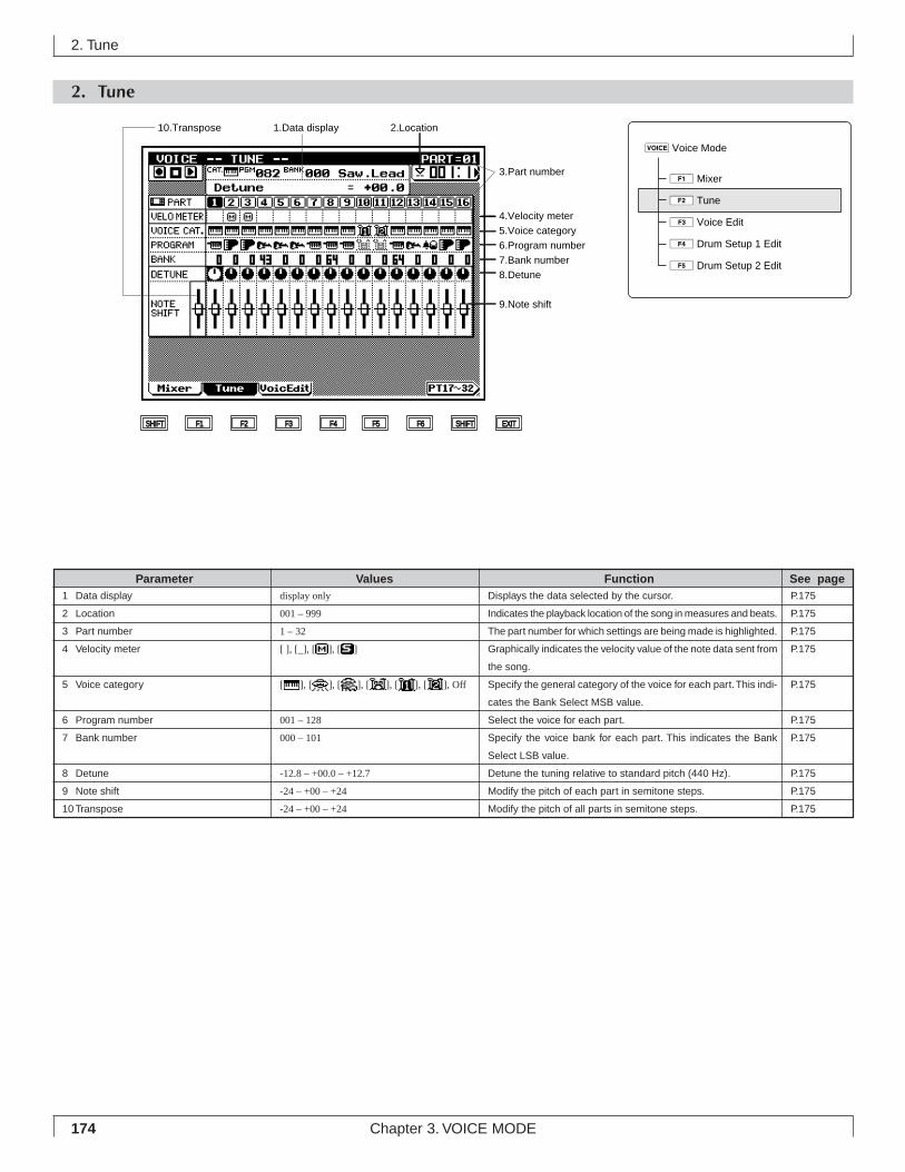
174 Chapter 3. VOICE MODE
2. Tune
2. Tune
3.Part number
4.Velocity meter
5.Voice category
6.Program number
7.Bank number
8.Detune
9.Note shift
SHIFT F1 F2 F3 F4 F5 F6 SHIFT EXIT
10.Transpose 1.Data display 2.Location
Displays the data selected by the cursor.
Indicates the playback location of the song in measures and beats.
The part number for which settings are being made is highlighted.
Graphically indicates the velocity value of the note data sent from
the song.
Specify the general category of the voice for each part. This indi-
cates the Bank Select MSB value.
Select the voice for each part.
Specify the voice bank for each part. This indicates the Bank
Select LSB value.
Detune the tuning relative to standard pitch (440 Hz).
Modify the pitch of each part in semitone steps.
Modify the pitch of all parts in semitone steps.
display only
001 – 999
1 – 32
[ ], [_], [ ], [ ]
[ ], [ ], [ ], [ ], [ ], [ ], Off
001 – 128
000 – 101
-12.8 – +00.0 – +12.7
-24 – +00 – +24
-24 – +00 – +24
Parameter Values Function See pageP.175
P.175
P.175
P.175
P.175
P.175
P.175
P.175
P.175
P.175
1 Data display
2 Location
3 Part number
4 Velocity meter
5 Voice category
6 Program number
7 Bank number
8 Detune
9 Note shift
10 Transpose
3Voice Edit
4Drum Setup 1 Edit
5Drum Setup 2 Edit
vVoice Mode
1Mixer
2Tune
175
3
Chapter 3. VOICE MODE
• Here you can make detune and note shift settings for eachpart that will apply during song playback or recording.
• These settings can be made while the song is playing back,and tracks can also be muted or soloed, just as in Song mode.
1. Press v.▼ The indicator above v will light, and you will enter
Voice mode.
2. Press 2 (Tune) to access the Tune page.
3. Use d/u or l/r to select apart. You can switch between the screens for parts 1–16 and parts 17–32 by pressing 6.
4. Move the cursor to the parameter that you wish to set.
5. Use n/y, the data dial, or the numeric keypad →e to set the value.
• In Voice mode, keys such as r, s, t and r/fwill function in the same way as in Song Play mode. Youcan use these keys to listen to the playback while you modifythe settings in realtime.
• s + data dial or s + n/y will increase ordecrease the setting of all parts by the same value.
• s + numeric keypad → e will set all parts to thesame value.
Operations for “1. Data display” – “7. Bank number” are the sameas in the Mixer page. For details on these parameters, refer to theexplanations for the Mixer page (→ p.170).
8. Detune• This detunes the tuning relative to the standard pitch (440
Hz).• This lets you make fine changes in the pitch of each part.• Setting the melody part slightly sharp will make the melody
stand out, and setting the bass part slightly flat will give itadditional weight.
01011101 -12.8–+00.0–+12.7
9. Note shift• This adjusts the pitch of each part in semitone steps.
01011101 -24–+00–+24
10. Transpose• This adjusts the pitch of all parts in semitone steps.
01011101 -24–+00–+24
2. Tune
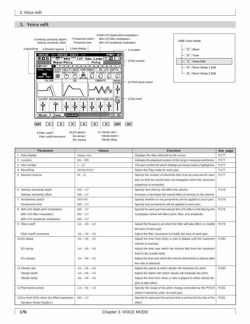
176 Chapter 3. VOICE MODE
3. Voice edit
3. Voice edit
SHIFT F1 F2 F3 F4 F5 F6 SHIFT EXIT
2.Location
13.Dry level
12.Pitch bend control
3.Part number
10.EG attack / EG decay / EG release
11.Vibrato rate / Vibrato depth / Vibrato delay
9.Filter cutoff / Filter cutoff resonance
4.Mono/Poly 5.Element reserve
6.Velocity sensitivity depth / Velocity sensitivity offset
7.Portamento switch / Portamento time
1.Data display
8.MW LFO depth pitch modulation / MW LFO filter modulation / MW LFO amplitude modulation
Parameter Values Function See pageP.177
P.177
P.177
P.177
P.177
P.178
P.179
P.179
P.179
P.180
P.180
P.181
P.181
1 Data display
2 Location
3 Part number
4 Mono/Poly
5 Element reserve
6 Velocity sensitivity depth
Velocity sensitivity offset
7 Portamento switch
Portamento time
8 MW LFO depth pitch modulation
MW LFO filter modulation
MW LFO amplitude modulation
9 Filter cutoff
Filter cutoff resonance
10 EG attack
EG decay
EG release
11 Vibrato rate
Vibrato depth
Vibrato delay
12 Pitch bend control
13 Dry level (Only when the Effect parameter
Variation Mode=System.)
Displays the data selected by the cursor.
Indicates the playback location of the song in measures and beats.
The part number for which settings are being made is highlighted.
Select the Play mode for each part.
Specify the number of elements that must be reserved for each
part so that the sound does not disappear when the maximum
polyphony is exceeded.
Specify how velocity will affect the volume.
Increase or decrease the overall effect of velocity on the volume.
Specify whether or not portamento will be applied to each part.
Specify how portamento will be applied to each part.
Specify for each part how deeply the LFO effect controlled by the
modulation wheel will affect pitch, filter, and amplitude.
Adjust the frequency at which the filter will take effect, to modify
the tone of each part.
Adjust the filter resonance to modify the tone of each part.
Adjust the time from when a note is played until the maximum
volume is reached.
Adjust the time over which the volume falls from the maximum
level to the sustain level.
Adjust the time over which the volume diminishes to silence after
the note is released.
Adjust the speed at which vibrato will modulate the pitch.
Adjust the depth with which vibrato will modulate the pitch.
Adjust the time from when a note is played to when vibrato be-
gins to take effect.
Specify the range of the pitch change controlled by the PITCH
wheel in semitone units, for each part.
Specify for each part the amount that is sent to the Dry line of the
effect.
display only
001 – 999
1 – 32
MONO/POLY
00 – 32
000 – 127
000 – 127
OFF/ON
000 – 127
000 – 127
000 – 127
000 – 127
-64 – +00 – +63
-64 – +00 – +63
-64 – +00 – +63
-64 – +00 – +63
-64 – +00 – +63
-64 – +00 – +63
-64 – +00 – +63
-64 – +00 – +63
-24 – +00 – +24
000 – 127
4Drum Setup 1 Edit
5Drum Setup 2 Edit
vVoice Mode
1Mixer
2Tune
3Voice Edit
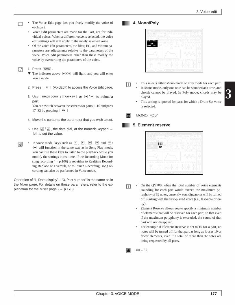
177
3
Chapter 3. VOICE MODE
• The Voice Edit page lets you freely modify the voice ofeach part.
• Voice Edit parameters are made for the Part, not for indi-vidual voices. When a different voice is selected, the voiceedit settings will still apply to the newly selected voice.
• Of the voice edit parameters, the filter, EG, and vibrato pa-rameters are adjustments relative to the parameters of thevoice. Voice edit parameters other than these modify thevoice by overwriting the parameters of the voice.
1. Press v.▼ The indicator above v will light, and you will enter
Voice mode.
2. Press 3 (VoicEdit) to access the Voice Edit page.
3. Use d/u or l/r to select apart.You can switch between the screens for parts 1–16 and parts17–32 by pressing 6.
4. Move the cursor to the parameter that you wish to set.
5. Use n/y, the data dial, or the numeric keypad →e to set the value.
• In Voice mode, keys such as r, e, s, t and r/f will function in the same way as in Song Play mode.You can use these keys to listen to the playback while youmodify the settings in realtime. If the Recording Mode forsong recording (→ p.106) is set either to Realtime Record-ing Replace or Overdub, or to Punch Recording, song re-cording can also be performed in Voice mode.
Operation of “1. Data display” – “3. Part number” is the same as inthe Mixer page. For details on these parameters, refer to the ex-planation for the Mixer page. (→ p.170)
4. Mono/Poly
• This selects either Mono mode or Poly mode for each part.• In Mono mode, only one note can be sounded at a time, and
chords cannot be played. In Poly mode, chords may beplayed.
• This setting is ignored for parts for which a Drum Set voiceis selected.
01011101 MONO, POLY
5. Element reserve
• On the QY700, when the total number of voice elementssounding for each part would exceed the maximum po-lyphony of 32 notes, currently-sounding notes will be turnedoff, starting with the first-played voice (i.e., last-note prior-ity).
• Element Reserve allows you to specify a minimum numberof elements that will be reserved for each part, so that evenif the maximum polyphony is exceeded, the sound of thatpart will not disappear.
• For example if Element Reserve is set to 10 for a part, nonotes will be turned off for that part as long as it uses 10 orfewer elements, even if a total of more than 32 notes arebeing requested by all parts.
01011101 00 – 32
3. Voice edit
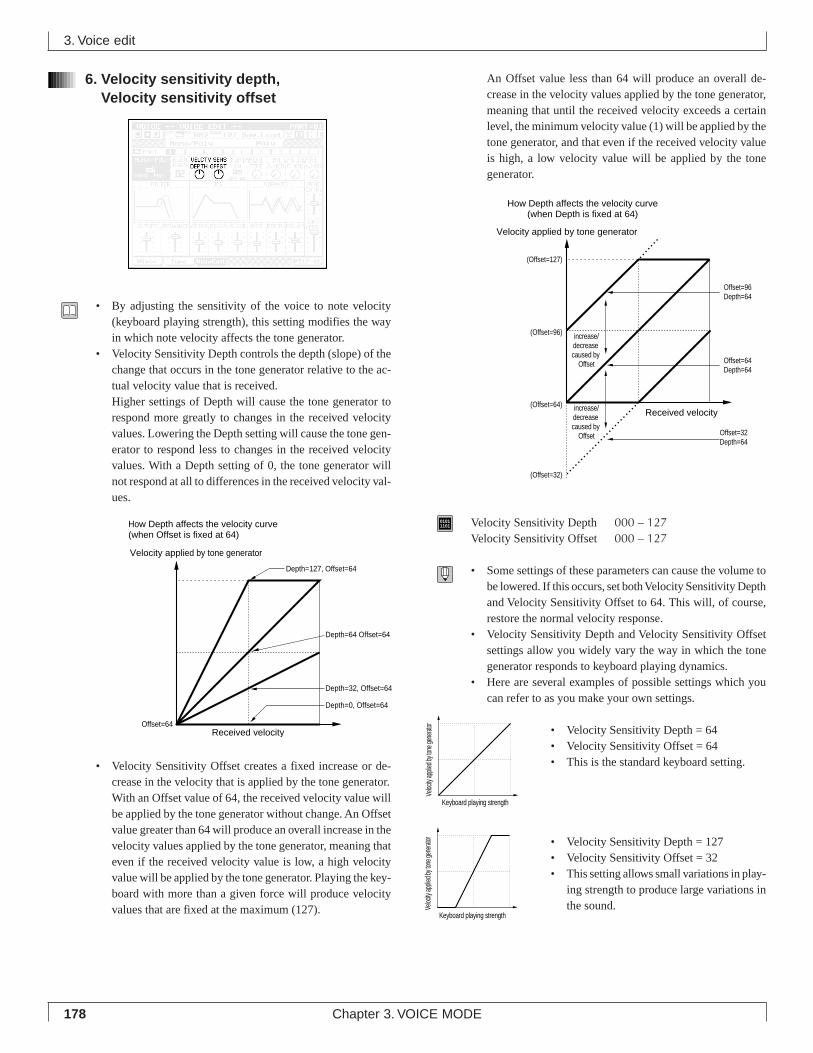
178 Chapter 3. VOICE MODE
3. Voice edit
An Offset value less than 64 will produce an overall de-crease in the velocity values applied by the tone generator,meaning that until the received velocity exceeds a certainlevel, the minimum velocity value (1) will be applied by thetone generator, and that even if the received velocity valueis high, a low velocity value will be applied by the tonegenerator.
01011101 Velocity Sensitivity Depth 000 – 127
Velocity Sensitivity Offset 000 – 127
• Some settings of these parameters can cause the volume tobe lowered. If this occurs, set both Velocity Sensitivity Depthand Velocity Sensitivity Offset to 64. This will, of course,restore the normal velocity response.
• Velocity Sensitivity Depth and Velocity Sensitivity Offsetsettings allow you widely vary the way in which the tonegenerator responds to keyboard playing dynamics.
• Here are several examples of possible settings which youcan refer to as you make your own settings.
• Velocity Sensitivity Depth = 64• Velocity Sensitivity Offset = 64• This is the standard keyboard setting.
• Velocity Sensitivity Depth = 127• Velocity Sensitivity Offset = 32• This setting allows small variations in play-
ing strength to produce large variations inthe sound.
6. Velocity sensitivity depth,Velocity sensitivity offset
• By adjusting the sensitivity of the voice to note velocity(keyboard playing strength), this setting modifies the wayin which note velocity affects the tone generator.
• Velocity Sensitivity Depth controls the depth (slope) of thechange that occurs in the tone generator relative to the ac-tual velocity value that is received.Higher settings of Depth will cause the tone generator torespond more greatly to changes in the received velocityvalues. Lowering the Depth setting will cause the tone gen-erator to respond less to changes in the received velocityvalues. With a Depth setting of 0, the tone generator willnot respond at all to differences in the received velocity val-ues.
• Velocity Sensitivity Offset creates a fixed increase or de-crease in the velocity that is applied by the tone generator.With an Offset value of 64, the received velocity value willbe applied by the tone generator without change. An Offsetvalue greater than 64 will produce an overall increase in thevelocity values applied by the tone generator, meaning thateven if the received velocity value is low, a high velocityvalue will be applied by the tone generator. Playing the key-board with more than a given force will produce velocityvalues that are fixed at the maximum (127).
How Depth affects the velocity curve(when Depth is fixed at 64)
Received velocity
Offset=96Depth=64
Velocity applied by tone generator
(Offset=96)
(Offset=64)
(Offset=32)
Offset=64Depth=64
Offset=32Depth=64
(Offset=127)
increase/decrease caused by
Offset
increase/decrease caused by
Offset
Keyboard playing strength
Veloc
ity ap
plied
by to
ne ge
nerat
or
Keyboard playing strength
Veloc
ity ap
plied
by to
ne ge
nerat
or
How Depth affects the velocity curve(when Offset is fixed at 64)
Offset=64
Velocity applied by tone generator
Depth=64 Offset=64
Depth=127, Offset=64
Depth=32, Offset=64
Depth=0, Offset=64
Received velocity
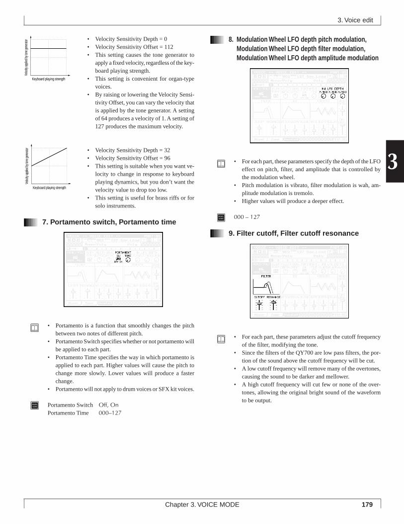
179
3
Chapter 3. VOICE MODE
• Velocity Sensitivity Depth = 0• Velocity Sensitivity Offset = 112• This setting causes the tone generator to
apply a fixed velocity, regardless of the key-board playing strength.
• This setting is convenient for organ-typevoices.
• By raising or lowering the Velocity Sensi-tivity Offset, you can vary the velocity thatis applied by the tone generator. A settingof 64 produces a velocity of 1. A setting of127 produces the maximum velocity.
• Velocity Sensitivity Depth = 32• Velocity Sensitivity Offset = 96• This setting is suitable when you want ve-
locity to change in response to keyboardplaying dynamics, but you don’t want thevelocity value to drop too low.
• This setting is useful for brass riffs or forsolo instruments.
7. Portamento switch, Portamento time
• Portamento is a function that smoothly changes the pitchbetween two notes of different pitch.
• Portamento Switch specifies whether or not portamento willbe applied to each part.
• Portamento Time specifies the way in which portamento isapplied to each part. Higher values will cause the pitch tochange more slowly. Lower values will produce a fasterchange.
• Portamento will not apply to drum voices or SFX kit voices.
01011101 Portamento Switch Off, On
Portamento Time 000–127
8. Modulation Wheel LFO depth pitch modulation,Modulation Wheel LFO depth filter modulation,Modulation Wheel LFO depth amplitude modulation
• For each part, these parameters specify the depth of the LFOeffect on pitch, filter, and amplitude that is controlled bythe modulation wheel.
• Pitch modulation is vibrato, filter modulation is wah, am-plitude modulation is tremolo.
• Higher values will produce a deeper effect.
01011101 000 – 127
9. Filter cutoff, Filter cutoff resonance
• For each part, these parameters adjust the cutoff frequencyof the filter, modifying the tone.
• Since the filters of the QY700 are low pass filters, the por-tion of the sound above the cutoff frequency will be cut.
• A low cutoff frequency will remove many of the overtones,causing the sound to be darker and mellower.
• A high cutoff frequency will cut few or none of the over-tones, allowing the original bright sound of the waveformto be output.
3. Voice edit
Keyboard playing strength
Veloc
ity ap
plied
by to
ne ge
nerat
or
Keyboard playing strength
Veloc
ity ap
plied
by to
ne ge
nerat
or
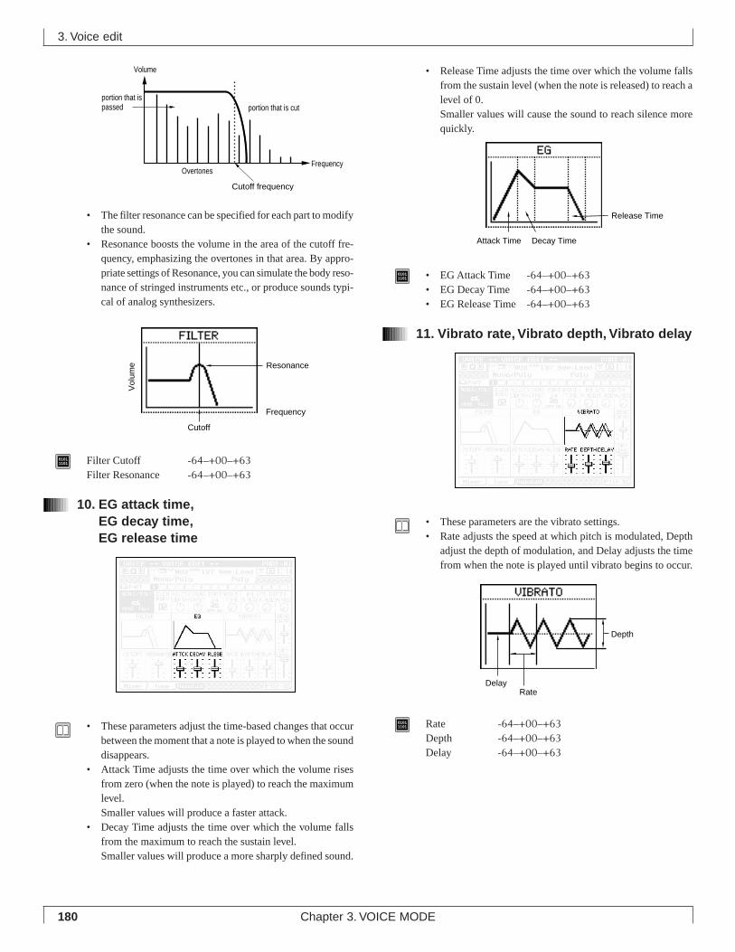
180 Chapter 3. VOICE MODE
• The filter resonance can be specified for each part to modifythe sound.
• Resonance boosts the volume in the area of the cutoff fre-quency, emphasizing the overtones in that area. By appro-priate settings of Resonance, you can simulate the body reso-nance of stringed instruments etc., or produce sounds typi-cal of analog synthesizers.
01011101 Filter Cutoff -64–+00–+63
Filter Resonance -64–+00–+63
10. EG attack time,EG decay time,EG release time
• These parameters adjust the time-based changes that occurbetween the moment that a note is played to when the sounddisappears.
• Attack Time adjusts the time over which the volume risesfrom zero (when the note is played) to reach the maximumlevel.Smaller values will produce a faster attack.
• Decay Time adjusts the time over which the volume fallsfrom the maximum to reach the sustain level.Smaller values will produce a more sharply defined sound.
3. Voice edit
• Release Time adjusts the time over which the volume fallsfrom the sustain level (when the note is released) to reach alevel of 0.Smaller values will cause the sound to reach silence morequickly.
01011101 • EG Attack Time -64–+00–+63
• EG Decay Time -64–+00–+63• EG Release Time -64–+00–+63
11. Vibrato rate, Vibrato depth, Vibrato delay
• These parameters are the vibrato settings.• Rate adjusts the speed at which pitch is modulated, Depth
adjust the depth of modulation, and Delay adjusts the timefrom when the note is played until vibrato begins to occur.
01011101 Rate -64–+00–+63
Depth -64–+00–+63Delay -64–+00–+63
Frequency
Volume
Cutoff frequency
Overtones
portion that is cutportion that is passed
Attack Time Decay Time
Release Time
Rate
Depth
Delay
Resonance
Cutoff
Frequency
Vol
ume
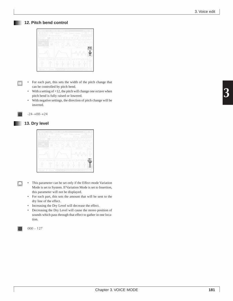
181
3
Chapter 3. VOICE MODE
3. Voice edit
12. Pitch bend control
• For each part, this sets the width of the pitch change thatcan be controlled by pitch bend.
• With a setting of +12, the pitch will change one octave whenpitch bend is fully raised or lowered.
• With negative settings, the direction of pitch change will beinverted.
01011101 -24–+00–+24
13. Dry level
• This parameter can be set only if the Effect mode VariationMode is set to System. If Variation Mode is set to Insertion,this parameter will not be displayed.
• For each part, this sets the amount that will be sent to thedry line of the effect.
• Increasing the Dry Level will decrease the effect.• Decreasing the Dry Level will cause the stereo position of
sounds which pass through that effect to gather in one loca-tion.
01011101 000 – 127
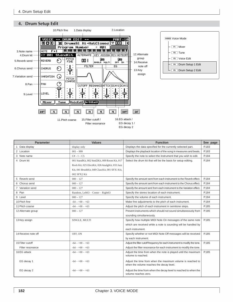
182 Chapter 3. VOICE MODE
4. Drum Setup Edit
4. Drum Setup Edit
Parameter Values Function See pageP.183
P.183
P.184
P.184
P.184
P.184
P.184
P.184
P.184
P.184
P.185
P.185
P.185
P.185
P.185
P.185
1 Data display
2 Location
3 Note name
4 Drum kit
5 Reverb send
6 Chorus send
7 Variation send
8 Pan
9 Level
10 Pitch fine
11 Pitch coarse
12 Alternate group
13 Key assign
14 Receive note off
15 Filter cutoff
Filter resonance
16 EG attack
EG decay 1
EG decay 2
Displays the data specified for the currently selected part.
Displays the playback location of the song in measures and beats.
Specify the note to select the instrument that you wish to edit.
Select the drum kit that will be the basis for setup editing.
Specify the amount sent from each instrument to the Reverb effect.
Specify the amount sent from each instrument to the Chorus effect.
Specify the amount sent from each instrument to the Variation effect.
Specify the stereo location of each instrument.
Specify the volume of each instrument.
Make fine adjustments to the pitch of each instrument.
Adjust the pitch of each instrument in semitone steps.
Prevent instruments which should not sound simultaneously from
sounding simultaneously.
Specify how multiple MIDI Note On messages of the same note
which are received while a note is sounding will be handled by
each instrument.
Specify whether or not MIDI Note Off messages will be received
by each instrument.
Adjust the filter cutoff frequency for each instrument to modify the tone.
Adjust the filter resonance for each instrument to modify the tone.
Adjust the time from when the note is played until the maximumvolume is reached.
Adjust the time from when the maximum volume is reached towhen the volume reaches the decay level.
Adjust the time from when the decay level is reached to when thevolume reaches zero.
display only
001 – 999
C# - 1 – C5
001 StandKit, 002 Stnd2Kit, 009 Room Kit, 017
Rock Kit, 025 ElectKit, 026 AnalgKit, 033 Jazz
Kit, 041 BrushKit, 049 ClascKit, 001 SFX1 Kit,
002 SFX2 Kit
000 – 127
000 – 127
000 – 127
Random, Left63 – Center – Right63
000 – 127
-64 – +00 – +63
-64 – +00 – +63
000 – 127
SINGLE, MULTI
OFF, ON
-64 – +00 – +63
-64 – +00 – +63
-64 – +00 – +63
-64 – +00 – +63
-64 – +00 – +63
SHIFT F1 F2 F3 F4 F5 F6 SHIFT EXIT
16.EG attack / EG decay 1 / EG decay 2
15.Filter cutoff / Filter resonance
11.Pitch coarse
3.Note name4.Drum kit
5.Reverb send
6.Chorus send
7.Variation send
8.Pan
9.Level
1.Data display10.Pitch fine 2.Location
12.Alternate group
13.Key
assign
14.Receive
note off
vVoice Mode
1Mixer
2Tune
3Voice Edit
4Drum Setup 1 Edit
5Drum Setup 2 Edit
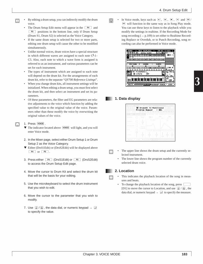
183
3
Chapter 3. VOICE MODE
• By editing a drum setup, you can indirectly modify the drumvoice.
• The Drum Setup Edit menu will appear in the 4 and5 positions in the bottom line, only if Drum Setup(Drum S1, Drum S2) is selected as the Voice Category.
• If the same drum setup is selected for two or more parts,editing one drum setup will cause the other to be modifiedsimultaneously.
• Unlike normal voices, drum voices have a special structurein which different waves are assigned to each note C
#-1–
C5. Also, each note to which a wave form is assigned isreferred to as an instrument, and various parameters can beset for each instrument.
• The types of instrument which are assigned to each notewill depend on the drum kit. For the arrangements of eachdrum kit, refer to the separate “QY700 Reference Listings”.
• When you change drum kits, all instrument settings will beinitialized. When editing a drum setup, you must first selectthe drum kit, and then select an instrument and set its pa-rameters.
• Of these parameters, the filter and EG parameters are rela-tive adjustments to the voice which function by adding thespecified value to the original value of the voice. Param-eters other than these modify the voice by overwriting theoriginal values of the voice.
1. Press v.▼ The indicator located above v will light, and you will
enter Voice mode.
2. In the Mixer page, select either Drum Setup 1 or DrumSetup 2 as the Voice Category.
▼ Either (DrsS1Edit) or (DrsS2Edit) will be displayed above4 or 5.
3. Press either 4 (DrsS1Edit) or 5 (DrsS2Edit)to access the Drum Setup Edit page.
4. Move the cursor to Drum Kit and select the drum kitthat will be the basis for your editing.
5. Use the microkeyboard to select the drum instrumentthat you wish to edit.
6. Move the cursor to the parameter that you wish tomodify.
7. Use n/y, the data dial, or numeric keypad → eto specify the value.
4. Drum Setup Edit
• In Voice mode, keys such as r, e, s, t and r/f will function in the same way as in Song Play mode.You can use these keys to listen to the playback while youmodify the settings in realtime. If the Recording Mode forsong recording (→ p.109) is set either to Realtime Record-ing Replace or Overdub, or to Punch Recording, song re-cording can also be performed in Voice mode.
1. Data display
• The upper line shows the drum setup and the currently se-lected instrument.
• The lower line shows the program number of the currentlyselected drum voice.
2. Location• This indicates the playback location of the song in meas-
ures and beats.• To change the playback location of the song, press d
[D1] to move the cursor to Location, and use n/y, thedata dial, or numeric keypad → e to specify the measure.
184 Chapter 3. VOICE MODE
3. Note name• Specify the note to select the instrument that you wish to
edit.• The types of instrument which are assigned to each note
will depend on the drum kit. For the arrangements of eachdrum kit, refer to the separate “QY700 Reference Listings”.
01011101 C#-1 – C5
4. Drum kit• Select the drum kit that will be the basis of your setup edit-
ing. When you change drum kits, the instruments which areassigned to each note will also change.
• When you change drum kits, all Drum Setup Edit param-eters will be initialized. Select a drum kit first, and thenmodify the parameters.
01011101 001 StandKit, 002 Stnd2Kit, 009 Room Kit,
017 Rock Kit, 025 ElectKit, 026 AnalgKit,033 Jazz Kit, 041 BrushKit, 049 ClascKit,001 SFX1 Kit, 002 SFX2 Kit
5. Reverb send• Specify the amount that will be sent to the Reverb effect
from each instrument.• The actual depth of the reverb will also be affected by the
mixer setting Reverb Send (→ p.170) and by the Effect modesetting Reverb Return (→ p.191). As you adjust this param-eter, keep in mind the relationship to these other param-eters.
01011101 000 – 127
6. Chorus send• Specify the amount that will be sent to the Chorus effect
from each instrument.• The actual depth of the chorus will also be affected by the
mixer setting Chorus Send (→ p.170) and by the Effect modesetting Chorus Return (→ p.192). As you adjust this pa-rameter, keep in mind the relationship to these other param-eters.
01011101 000 – 127
7. Variation send• When the Effect mode parameter Variation Mode (→ p.191)
is set to System, this parameter functions as the VariationSend Level.This specifies the amount that will be sent to the Variationeffect from each instrument, adjusting the depth of the ef-fect.As you adjust this parameter, you should also keep in mindthe setting of the Effect mode parameter Variation Return.
• When the Effect mode parameter Variation Mode (→ p.191)is set to Insertion, setting this parameter to 000 will turnVariation=Off, and setting it to 1–127 will turn Variation=On.
01011101 Variation Send Level
000 – 127
8. Pan• This specifies the stereo location of each instrument.• Arranging the instruments in the same stereo locations as a
real drum set will produce the most natural result.
01011101 Random, Left63–Center–Right63
• Random produces a special effect in which the stereo loca-tion of the sound varies randomly for each note.
• Left63 (far left)–Center (center)–Right63 (far right)
9. Level• Set the volume of each instrument.
01011101 000 – 127
10. Pitch fine• Make fine adjustments to the pitch of each instrument.• This setting is made in steps of 1 cent (1 cent is 1/100th of
a semitone).
01011101 -64–+00–+63
4. Drum Setup Edit
185
3
Chapter 3. VOICE MODE
11. Pitch coarse• Adjust the pitch of each instrument in semitone steps.• With a value of +00, the instrument will sound at the same
pitch at which it was sampled.• By modifying the pitch, you can make an instrument sound
heavier, or create melodic toms, etc.• For fine tuning, use 10. Pitch fine.
01011101 -64–+00–+63
12. Alternate group• This setting lets you prevent instruments which should not
sound simultaneously from sounding simultaneously.• Instruments which are set to the same Alternate Group
number will not sound simultaneously.• Instruments which would never sound simultaneously in real
life (such as closed and open hi-hat sounds) should be set tothe same number.
• Instruments for which an Alternate Group is specified willalways have a Key Assign Mode setting of Single.
01011101 Off, 001 – 127
13. Key assign• Specify how multiple MIDI Note On messages of the same
note which are received while a note is sounding will behandled by each instrument.
• With a Key Assign setting of Single, the currently-sound-ing note will be damped (will stop sounding) before thenote is re-triggered.
• With a Key Assign setting of Multi, the currently-soundingnote will continue sounding, and the next note will be playedtogether with the currently-sounding note.
• This effect is particularly noticeable for sounds with a slowdecay, such as cymbals. In general, a Key Assign setting ofMulti will sound more natural.
01011101 Single, Multi
14. Receive note off• Specify whether or not MIDI Note Off messages will be
received by each instrument.• If this is on, MIDI Note Off messages will be received to
damp (turn off) the currently-sounding note.• If this is off, MIDI Note Off messages will be ignored, and
the note will continue sounding until it ends naturally. Nor-mally you will use a setting of “off.”
• Use a setting of “on” if you wish to damp cymbals whilethey are still sounding, etc.
01011101 Off, On
15. Filter cutoff, Filter resonance• Cutoff adjusts the filter cutoff frequency of each instrument.• By modifying the cutoff, you can brighten or darken the
tone.• Resonance adjusts the filter resonance for each instrument.• By modifying the resonance, you can adjust the emphasis
of the overtones in the region of the cutoff frequency, creat-ing a more distinctive tone.
01011101 Filter Cutoff -64–+00–+63
Filter Resonance -64–+00–+63
16. EG attack, EG decay 1, EG decay 2• These parameters adjust the way in which the volume of
each instrument changes over time.
4. Drum Setup Edit
Attack
Decay 1
Decay Level
Decay 2
time at which the key was pressed
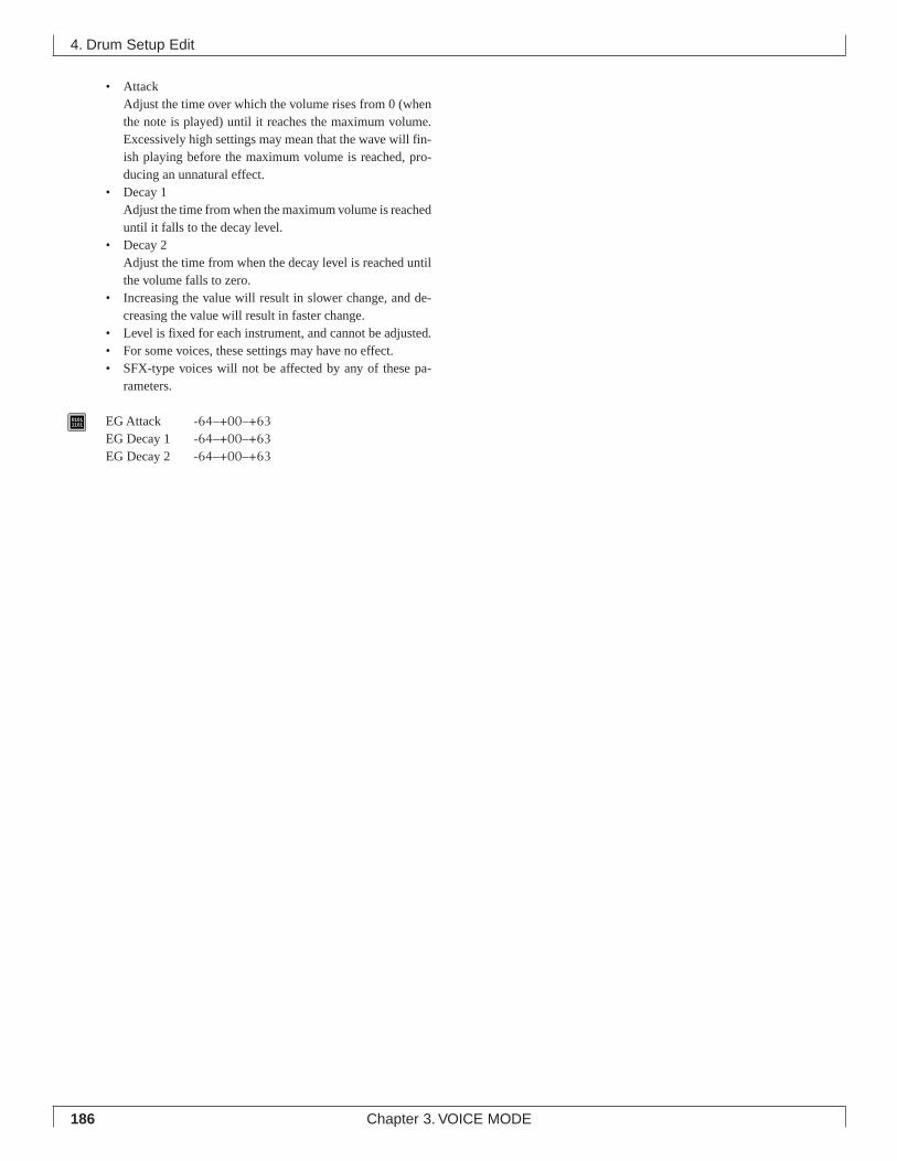
186 Chapter 3. VOICE MODE
• AttackAdjust the time over which the volume rises from 0 (whenthe note is played) until it reaches the maximum volume.Excessively high settings may mean that the wave will fin-ish playing before the maximum volume is reached, pro-ducing an unnatural effect.
• Decay 1Adjust the time from when the maximum volume is reacheduntil it falls to the decay level.
• Decay 2Adjust the time from when the decay level is reached untilthe volume falls to zero.
• Increasing the value will result in slower change, and de-creasing the value will result in faster change.
• Level is fixed for each instrument, and cannot be adjusted.• For some voices, these settings may have no effect.• SFX-type voices will not be affected by any of these pa-
rameters.
01011101 EG Attack -64–+00–+63
EG Decay 1 -64–+00–+63EG Decay 2 -64–+00–+63
4. Drum Setup Edit
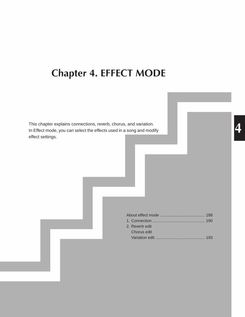
Chapter 4. EFFECT MODE
This chapter explains connections, reverb, chorus, and variation.
In Effect mode, you can select the effects used in a song and modify
effect settings.
About effect mode ........................................ 1881. Connection ............................................... 1902. Reverb edit
Chorus editVariation edit ............................................ 193
4
188 Chapter 4. EFFECT MODE
About effect mode
About effect mode
• In Effect mode, you can select the effects used in a songand modify effect settings.
• Effect mode does not have a “top” page which always ap-pears first when you press the MODE key. (The previously-selected page will appear.)
• Effect mode has four sub-mode pages, and these are se-lected by the 1 – 4 function keys.Pressing 1 (Connect) accesses the Connection page.Here you can specify the connection mode, the Effect Typefor each effect, and the return levels etc. (→ p.190)Pressing 2 (Reverb) accesses the Reverb Edit page.Here you can select the Reverb Type, and make reverb pa-rameter settings. (→ p.193)Pressing 3 (Chorus) accesses the Chorus Edit page.Here you can select the Chorus Type, and make chorus pa-rameter settings. (→ p.193)Pressing 4 (Vari.) accesses the Variation Edit page.Here you can select the Variation Type, and make variationparameter settings. (→ p.193)
• The structure of the QY700’s effects is greatly dependenton the Variation Mode setting of the Connection page.
• If exclusive messages such as “GM Mode On” or “XG Sys-tem On” that make effect settings are included in a song,settings made in Effect mode or by control changes will beignored.
• If you want the settings of Effect mode to be reflected in thedata, highlight XG Header in the Save page of Disk modewhen saving the song to a Standard MIDI File etc. (→ p.307)
• For details on Variation mode and effect structure, refer to“Chapter 1. BASIC CONCEPTS” (→ p.47).
2Reverb edit
3Chorus edit
4Variation edit
eEffect mode
1Ê Connection
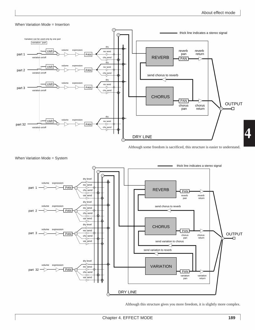
189Chapter 4. EFFECT MODE
4
About effect mode
When Variation Mode = Insertion
rev send
cho send
dry
reverb return
chorus return
send chorus to reverb
DRY LINE
PAN
reverb pan
chorus pan
OUTPUT
thick line indicates a stereo signal
rev send
cho send
dry
rev send
cho send
dry
rev send
cho send
dry
variation part
part 3
part 32
Variation can be used only by one part
part 1
part 2
VAR
VAR
VAR
VAR
variation on/off
variation on/off
variation on/off
variation on/offPAN
volume expression
PAN
volume expression
PAN
volume expression
PAN
volume expression
REVERB
CHORUSPAN
Although some freedom is sacrificed, this structure is easier to understand.
part 1
VARIATION
REVERB
send chorus to reverb
send variation to chorus
send variation to reverb
DRY LINE
PANreverb return
reverb pan
OUTPUT
thick line indicates a stereo signal
CHORUS
part 2
part 3
part 32
chorus return
chorus pan
variation return
variation pan
var send
var send
var send
rev send
rev send
rev send
cho send
cho send
cho send
dry level
dry level
dry level
dry level
var send
rev send
cho send
PAN
PAN
PAN
volume expression
PAN
volume expression
PAN
volume expression
PAN
volume expression
thick line indicates a stereo signal
When Variation Mode = System
Although this structure gives you more freedom, it is slightly more complex.
190 Chapter 4. EFFECT MODE
1. Connection
1. Connection
3.Reverb type
5.Reverb pan
6.Chorus type
8.Chorus pan
9.Send chorus to
reverb
4.Reverb return
7.Chorus return
SHIFT F1 F2 F3 F4 F5 F6 SHIFT EXIT
10.Variation type 1.Data display 2.Variation mode
This indicates the parameter setting at the cursor location.
Specify whether the Variation effect will be used as an Insertion
effect or as a System effect.
Select the reverb type.
Specify the amount of return from the reverb effect.
Set the stereo location of the sound processed by reverb.
Select the chorus type.
Specify the amount of return from the chorus effect.
Set the stereo location of the sound processed by chorus.
Specify the amount sent from chorus to reverb.
Select the variation type.
Specify the amount of return from the variation effect.
Set the stereo location of the sound processed by variation.
Specify the amount sent from variation to chorus.
Specify the amount sent from variation to reverb.
display only
Insertion, System
11 types
000 – 127
Left63 – Center – Right63
11 types
000 – 127
Left63 – Center – Right63
000 – 127
43 types
000 – 127
Left63 – Center – Right63
000 – 127
000 – 127
Parameter Values Function See pageP.191
P.191
P.191
P.191
P.191
P.191
P.192
P.192
P.192
P.192
P.192
P.192
P.192
P.192
1 Data display
2 Variation mode
3 Reverb type
4 Reverb return
5 Reverb pan
6 Chorus type
7 Chorus return
8 Chorus pan
9 Send chorus to reverb
10 Variation type
11 Variation return
12 Variation pan
13 Send variation to chorus
14 Send variation to reverb
2Reverb edit
3Chorus edit
4Variation edit
eEffect mode
1ÊConnection
*11-14 are available only when Variation Mode = “System”
12.Variation pan
13.Send variation to chorus
SHIFT F1 F2 F3 F4 F5 F6 SHIFT EXIT
11.Variation return
14. Send variation to reverb
191Chapter 4. EFFECT MODE
4
• In the Connection page you can make settings such as theVariation Mode, the effect type for each effect, and returnlevels.
• For details on how the effects work, refer to “Chapter 1.BASIC CONCEPTS” (→ p.47).
1. Press e.▼ The indicator located above e will light, and one of
the four sub-modes of Effect mode (the last-selected sub-mode) will appear.
2. Press 1 (Connect) to access the Connectionpage.
3. Move the cursor to the parameter that you wish to set.
4. Use n/y, the data dial, or numeric keypad → eto specify the value.
• In Effect mode, keys such as p, s, t, and r/fwill function in the same way as in Song Play. Using thesekeys, you can modify settings in realtime while you listento the playback.
1. Data display• This displays the settings of the parameter where the cursor
is located.
2. Variation mode• This parameter lets you specify whether the Variation ef-
fect will function as an Insertion effect or as a System ef-fect. (→ p.48)
• If the Variation effect is used as an insertion effect, it can beused only by one specific part. In this case, a modulationwheel or foot controller can be used to control specifiedparameters.
• If the Variation effect is used as a system effect, it can beused by all parts in the same way as the Reverb and Choruseffects, with adjustable Send Level and Return Level. Inthis case, it will not be possible to use controllers to controlspecific parameters.
01011101 Insertion, System
• Insertion The Variation effect will function as an inser-tion effect.
• System The Variation effect will function as a systemeffect.
3. Reverb type• This sets the effect type of the reverb.
01011101 NO EFFECT, HALL 1, HALL 2, ROOM 1, ROOM 2, ROOM
3, STAGE 1, STAGE 2, PLATE, WHITE ROOM, TUNNEL,BASEMENT
4. Reverb return• This sets the amount that is returned from the reverb, ad-
justing the overall reverb effect for all parts.
01011101 000 – 127
5. Reverb pan• This sets the stereo location of the signal from the reverb
effect (the processed sound).
01011101 Left63 – Center –␣ Right63
• Left settings move the sound toward the left of the stereoimage, and Right settings toward the right. A setting ofCenter places the sound in the center.
6. Chorus type• This sets the effect type of the chorus.
01011101 NO EFFECT, CHORUS 1, CHORUS 2, CHORUS 3, CHO-
RUS 4, CELESTE 1, CELESTE 2, CELESTE 3, CELESTE 4,FLANGER 1, FLANGER 2, FLANGER 3
1. Connection
192 Chapter 4. EFFECT MODE
7. Chorus return• This sets the amount that is returned from the chorus, ad-
justing the overall chorus effect for all parts.
01011101 000 – 127
8. Chorus pan• This sets the stereo location of the signal from the chorus
effect (the processed sound).
01011101 Left63 –␣ Center – Right63
• Left settings move the sound toward the left of the stereoimage, and Right settings toward the right. A setting ofCenter places the sound in the center.
9. Send chorus to reverb• This sets the amount that is sent on the bus line connecting
the chorus effect to the reverb effect.
01011101 000 – 127
10. Variation type• This selects the Variation effect type.
01011101 NO EFFECT, HALL 1, HALL 2, ROOM 1, ROOM 2, ROOM
3, STAGE 1, STAGE 2, PLATE, DELAY LCR, DELAY L,R,ECHO, CROSSDELAY, ER1, ER2, GATE REV, REVRS GATE,KARAOKE 1, KARAOKE 2, KARAOKE 3, THRU, CHORUS1, CHORUS 2, CHORUS 3, CHORUS 4, CELESTE 1,CELESTE 2, CELESTE 3, CELESTE 4, FLANGER 1, FLANGER2, FLANGER 3, SYMPHONIC, ROTARY SP, TREMOLO,AUTO PAN, PHASER 1, PHASER 2, DISTORTION,OVERDRIVE, AMP SIM, 3-BAND EQ, 2-BAND EQ, AUTOWAH
11. Variation return(Available only if variation mode = System)
• This sets the amount that is returned from the variation, ad-justing the overall variation effect for all parts.
01011101 000 – 127
12. Variation pan(Available only if variation mode = System)
• This sets the stereo location of the signal from the variationeffect (the processed sound).
01011101 Left63 – Center – Right63
• Left settings move the sound toward the left of the stereoimage, and Right settings toward the right. A setting ofCenter places the sound in the center.
13. Send variation to chorus(Available only if variation mode = System)
• This sets the amount that is sent on the bus line connectingthe variation effect to the chorus effect.
01011101 000 – 127
14. Send variation to reverb(Available only if variation mode = System)
• This sets the amount that is sent on the bus line connectingthe variation effect to the reverb effect.
01011101 000 – 127
1. Connection
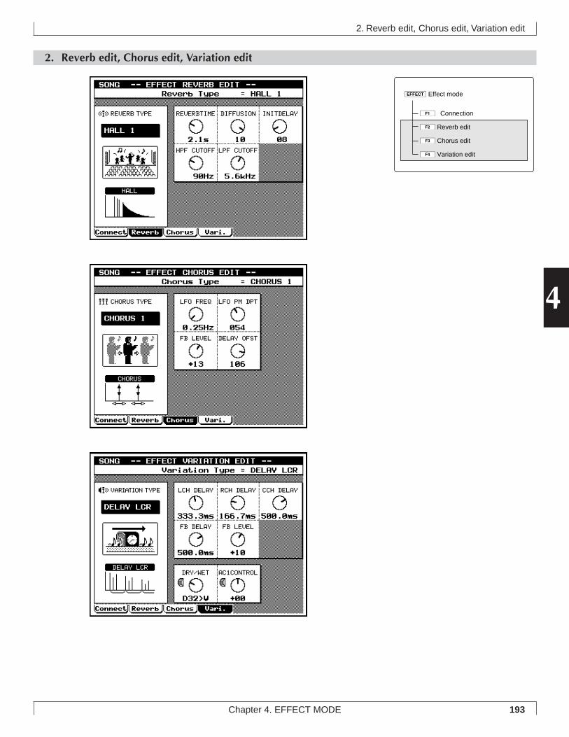
193Chapter 4. EFFECT MODE
4
2. Reverb edit, Chorus edit, Variation edit
2. Reverb edit, Chorus edit, Variation edit
eEffect mode
1ÊConnection
2Reverb edit
3Chorus edit
4Variation edit
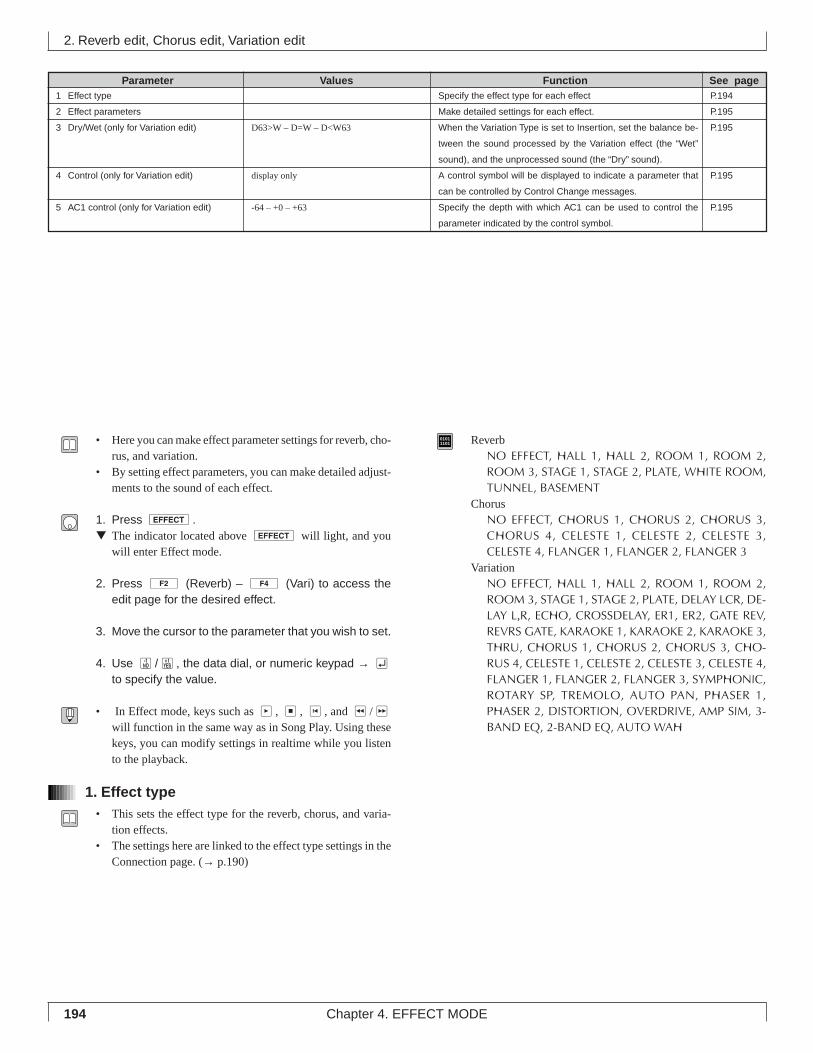
194 Chapter 4. EFFECT MODE
2. Reverb edit, Chorus edit, Variation edit
Specify the effect type for each effect
Make detailed settings for each effect.
When the Variation Type is set to Insertion, set the balance be-
tween the sound processed by the Variation effect (the “Wet”
sound), and the unprocessed sound (the “Dry” sound).
A control symbol will be displayed to indicate a parameter that
can be controlled by Control Change messages.
Specify the depth with which AC1 can be used to control the
parameter indicated by the control symbol.
D63>W – D=W – D<W63
display only
-64 – +0 – +63
Parameter Values Function See pageP.194
P.195
P.195
P.195
P.195
1 Effect type
2 Effect parameters
3 Dry/Wet (only for Variation edit)
4 Control (only for Variation edit)
5 AC1 control (only for Variation edit)
• Here you can make effect parameter settings for reverb, cho-rus, and variation.
• By setting effect parameters, you can make detailed adjust-ments to the sound of each effect.
1. Press e.▼ The indicator located above e will light, and you
will enter Effect mode.
2. Press 2 (Reverb) – 4 (Vari) to access theedit page for the desired effect.
3. Move the cursor to the parameter that you wish to set.
4. Use n/y, the data dial, or numeric keypad → eto specify the value.
• In Effect mode, keys such as p, s, t, and r/fwill function in the same way as in Song Play. Using thesekeys, you can modify settings in realtime while you listento the playback.
1. Effect type• This sets the effect type for the reverb, chorus, and varia-
tion effects.• The settings here are linked to the effect type settings in the
Connection page. (→ p.190)
01011101 Reverb
NO EFFECT, HALL 1, HALL 2, ROOM 1, ROOM 2,ROOM 3, STAGE 1, STAGE 2, PLATE, WHITE ROOM,TUNNEL, BASEMENT
ChorusNO EFFECT, CHORUS 1, CHORUS 2, CHORUS 3,CHORUS 4, CELESTE 1, CELESTE 2, CELESTE 3,CELESTE 4, FLANGER 1, FLANGER 2, FLANGER 3
VariationNO EFFECT, HALL 1, HALL 2, ROOM 1, ROOM 2,ROOM 3, STAGE 1, STAGE 2, PLATE, DELAY LCR, DE-LAY L,R, ECHO, CROSSDELAY, ER1, ER2, GATE REV,REVRS GATE, KARAOKE 1, KARAOKE 2, KARAOKE 3,THRU, CHORUS 1, CHORUS 2, CHORUS 3, CHO-RUS 4, CELESTE 1, CELESTE 2, CELESTE 3, CELESTE 4,FLANGER 1, FLANGER 2, FLANGER 3, SYMPHONIC,ROTARY SP, TREMOLO, AUTO PAN, PHASER 1,PHASER 2, DISTORTION, OVERDRIVE, AMP SIM, 3-BAND EQ, 2-BAND EQ, AUTO WAH
195Chapter 4. EFFECT MODE
4
• If Variation Mode is set to Insertion, setting the Effect Typeof the Variation effect to “No Effect” will mean that the partwhose Variation Switch is ON will not sound.
2. Effect parameters• Here you can make detailed settings for each effect.• Each effect type has different parameters.
3. Dry/Wet (only for Variation edit)• This sets the balance between the sound processed by the
Variation effect (the “Wet” sound), and the unprocessedsound (the “Dry” sound).
• This can be set only if Variation Type = Insertion. If Varia-tion Mode = System, this will be fixed at D32>W.
01011101 D63>W – D=W – D<W63
4. Control (only for Variation edit)• A symbol will be displayed to indicate a parameter that
can be controlled using control change messages.• When Variation Type is set to Insertion, this can be used for
parts whose Variation switch is ON.
5. AC1 control (only for Variation edit)• This specifies the depth with which AC1 (assignable con-
troller) can be used to control the parameter indicated bythe control symbol.
• With a setting of 0, control will not be possible. As thissetting is increased, a greater amount of control will be pos-sible. With negative settings, raising the controller will lowerthe parameter value.
• Assignable controllers are controllers whose control numbercan be set freely. The QY700 provides two assignable con-trollers: AC1 and AC2. Assignable controller settings aremade using Exclusive messages.
• This can be set only when Variation Type = Insertion. Thisparameter will not be displayed when Variation Mode = Sys-tem.
01011101 -64 – +0 –␣ +63
2. Reverb edit, Chorus edit, Variation edit
196 Chapter 4. EFFECT MODE
Memo
Chapter 5. PATTERN MODE
PATTERN MODE Overview .......................... 1981. PATCH...................................................... 2002. Play Effects .............................................. 2123. Pattern Voice Submode ............................ 2254. Pattern Effects .......................................... 2395. Phrase Recording .................................... 2476. Phrase Editing .......................................... 2547. Pattern Jobs ............................................. 256
5
You use PATTERN mode to record and edit user phrases, to assem-
ble preset and user phrases into patterns, and to set up the pattern
playback characteristics.
This chapter describes all PATTERN-mode operations: pattern ar-
rangement (style and sections), pattern play effects, voice and ef-
fects settings, phrase recording and editing, and pattern jobs.
198 Chapter 5. PATTERN MODE
PATTERN MODE Overview
• You use PATTERN mode to record and edit user phrases, toassemble phrases into patterns, and to set up the playbackcharacteristics for your patterns.
• The phrase is the basic unit of song-accompaniment pat-terns. A single phrase, for example, might provide a bassline for a bass part, a rhythm line for a rhythm part, or achord backing for a guitar part.
• The QY700 includes 3,876 built-in phrases (preset phrases)that you can use to build your patterns. In addition, you canrecord and edit your own, original user phrases: up to 99user phrases for each of the 64 available pattern styles. Forgeneral information about phrases, see Chapter 1. (→ p.37)
• During replay, the QY700 can modulate (transpose) phrasesto match a specified chord type and root. To do this, theQY700 uses an internal chord conversion table to convertthe phrase’s original chord/pitch relationships in accordancewith the target chord type (28 types) and root (12 roots).For general information about the chord conversion setup,see Chapter 1. (→ p.38)
• A pattern is a multitrack arrangement of phrases. The pat-tern can consist of up to 16 tracks (or parts), with each partproducing its own phrase sequence. Although each phrasereproduces a single instrument (voice), the pattern combinesthese phrases to produce a multivoice accompaniment —which may include, for example, multiple drum phrases, abass phrase, chord comps, and so on.
• The pattern is the basic unit of song accompaniment. Atany given instant the QY700 can play a single pattern only(consisting of up to 16 tracks of independent phrase se-quences). During replay, the QY700 switches from patternto pattern in accordance with the pattern sequence you havespecified.
• The QY700 organizes patterns within styles and sections.More precisely, each pattern exists as a section within a style.
• A style is a general accompaniment type, such as “TECHNO1” or “Hip Hop.” Each style consists of eight sections (Athrough H), which give different segments of the accompa-niment: intro section, first melody section, fill-in, ending,and so on. Each section is equivalent to one pattern. (Thus,“Style 1 Section A,” “Style 1 Section B,” and “Style 9 Sec-tion D” all identify distinct patterns.)
PATTERN MODE Overview
2Pattern Voice Setup
3Pattern Effects
4Phrase Solo
ePhrase Recording
ePhrase Edit
jPattern Job
1ÊPlay Effects
6Phrase Table
pPATCH
äOriginal phrase
äConverted phrase
Chord conversion
tableChord root
and type data
## ## #
#
# #
199Chapter 5. PATTERN MODE
5
• The QY700 provides 64 styles. Since you can set up 8 sec-tions for each style, you can create, store, and access up to512 patterns.
• You can transpose (modulate) an entire pattern by changingits source-chord value. The QY700 executes the modula-tion by transposing all of the phrase’s patterns accordingly(using the chord conversion table).
• For more information about patterns, refer to Chapter 1.(→ p.39)
Track Output Channels
• During pattern replay, the QY700 transmits pattern-trackdata to both the tone generator block and the MIDI OUTconnectors. You can set up the track/channel correspond-ence using the SONG mode’s Output Channel function. (→p.103)
• PATTERN mode consists of a main screen (PATCH screen),and six submodes. You can access the submodes from thePATCH screen by pressing 1, 2, 3, e,e, or j.
• Key operation from the PATCH screen is as follows.1(PlayFx) Move to Play Effects submode. (→ p.212)2(Voice) Move to Pattern Voice submode. (→
p.225)3(Effect) Move to Pattern Effects submode. (→
p.239)
4(PhrSolo)Select “phrase solo” operation: TheQY700 begins repeated playback of thecursor-selected phrase.
5(Rest) Enter a rest at the cursor-selected phraseposition.
6(Clear) Delete the cursor-selected phrase or rest.e Move to Phrase Recording submode.e Move to Phrase Editing submode.j Move to Pattern Job submode.
PATTERN MODE Overview
TR 1 Phrase no. Phrase no. • • •
TR 2 Phrase no. • • •
TR 3 Phrase no. • • •
TR 16 Phrase no. • • •
M1 M2 M3 • • •
TR 1 Phrase
TR 2 Phrase
TR 3 Phrase
TR 16 Phrase
M001 M002 • • •
Part 1
Part 16
Part 17
Part 32
MIDI OUT-A
MIDI OUT-B
Sequencer block (pattern tracks)
TR 1 Performance data
TR 2 Performance data
TR 16 Performance data
TR 17 Performance data
TR 32 Performance data
Sequence tracks
Sequencer block (Sequence tracks)
TO TG
MIDIOUT-A
MIDIOUT-B
Tone generator (TG) block
200 Chapter 5. PATTERN MODE
1. PATCH
1. PATCH
Selects the style.
Name of selected style.
Selects the section (pattern).
Name of pattern.
Selects next section.
Selects initial (default) chord root and type for pattern replay.
Selects use or nonuse of fingered-chord input.
Sets playback start location; or shows current playback location.
Shows total length of pattern.
Sets tempo for pattern playback.
Sets the pattern’s time signature.
Selects use of acoustic click.
Selects the click interval.
Sets number of lead-in measures to recording start.
Shows scale time, beat shift, or phrase name.
Pattern track.
Determines phrase location within pattern (by measure).
Indicates/selects track SOLO or track MUTE.
Proportionally adjusts playback length of phrases on track.
Shifts playback timing of phrases on track, in 16th-note incre-
ments.
Identifies/selects phrase.
01,...,64
View only
A,...,H
View only
A,...,H
C, C#, D, Eb, E, F, F#, G, Ab, A, Bb, BM, M7, 6, 7, m, m7, m6, mM7, m7(b5),
dim, aug, sus4, add9, M7(9), 6(9), 7(9),
madd9, M9, m7(9), m7(11), 7(b5), 7(#5),
7(b9), 7(#9), 7(13), 7(b13), 7sus4, 7(#11),
--- (THRU)
OFF, FINGRD
001,...,pattern length
Pattern length (in measures)
25.0,...,300.0
1/16,...,16/16; 1/8,..., 16/8; 1/4,...,8/4
Off, Rec, Ply, All
x, e, q, h, úOff, 1,...,8Ms
View only
1,...,16
M001,...,pattern length
: MUTE : SOLO
050%, 066%, 075%, 100%, 133%, 150%, 200%
-32,...,+00,...,+32 (*x)
Da,Db,Fa,Fb,Fc,DP,PC,PF,Ba,Bb,GC,GA,
GR,KC,KA,KR,PD,BR,SE,US
16,08,34
001,...,256 (preset); 001,...,099 (user)
1 Style number
Style name
2 Section
Pattern name
3 Section connection
4 Chord root
Chord type
5 Fingered-chord switch
6 Current measure
Measure length
7 Tempo
Meter (time signature)
8 Click mode
Click beat
Count
9 Data display
10 Track number
11 Measure
12 Track status
13 Scale time
14 Beat shift
15 Phrase number
Instrument category
Beat
Sequential no.
Parameter Values Function See pageP.202
P.202
P.202
P.203
P.204
P.204
P.204
P.205
P.205
P.205
P.205
P.206
P.206
P.207
P.207
SHIFT F1 F2 F3 F4 F5 F6 SHIFT EXIT
6. Current measure; pattern length
11. Measure
9. Data display
8. Click beat, click mode, and count
7. Tempo and meter
10. Track number
1. Style number and name2. Section, and pattern name 3. Section connection 5. Fingered-chord switch
4. Chord root and type
12. Track status
15. Phrase number, Phrase name
14. Beat shift13. Scale time
2Pattern Voice Setup
3Pattern Effects
4Phrase Solo
ePhrase Recording
ePhrase Edit
jPattern Job
1ÊPlay Effects
6Phrase Table
pPATCH
201Chapter 5. PATTERN MODE
5
1. PATCH
• When you enter PATTERN mode, the QY700 displays thePATCH screen. You can use this screen to create a pattern(by arranging phrases onto the 16 pattern tracks), or to se-lect and replay an existing pattern.
• During pattern playback, you can change the chord settingso that the pattern modulates. If you enable the fingered-chord switch, you can make the changes by playing appro-priate chords at the microkeyboard or at an external MIDIkeyboard.
• The lower half of the PATCH screen shows the pattern’sphrase arrangement, by measure and by track. You canchange the phrase settings directly at this screen. By select-ing different voices for each track, you can easily build andtry out a wide number of multipart variations (drum plusguitar plus bass, and so on).
To select and play a pattern
1. Press p.▼ The QY700 enters PATTERN mode. The PATTERN indi-
cator lamp comes on.
2. Select the pattern. (→ p.202)• Move the cursor to the style-number and section-letter ar-
eas on the screen, and make your selection using the datadial, n/y, or the numeric keypad.
3. Press p to start playback.• The PLAY indicator lamp comes on, and the QY700 begins
playback of the selected pattern. The QY700 repeats thepattern until you change the selection or switch playbackoff.
4. Press s to stop the playback.
To create a pattern
1. Press p.▼ The QY700 enters PATTERN mode. The PATTERN indi-
cator lamp comes on.
2. Select the pattern that you want to work on.• Move the cursor to the style-number and section-letter ar-
eas on the screen, and make your selection using the datadial, n/y, or the numeric keypad.
3. Set the pattern length and time signature. (→ p.204.)• Press d [D1] or d [D2] to move the cursor into
the appropriate setting area. Set the values using the datadial, n/y, or the numeric keypad.
4. Move the cursor to the appropriate phrase-entry loca-tion.
• Move the cursor to the appropriate track and measure loca-tion (lower half of the screen).
5. Make an initial selection using the data dial or n/y.▼ The QY700 displays the phrase name and number.
6. Complete the selection. (→ p.207)• The phrase number consists of three sections: the instru-
ment category, the beat value, and a sequential number. Movethe cursor to each of these sections as necessary, and makeyour selection using the data dial, n/y, or the numerickeypad.
• To enter a rest rather than a phrase: Press 5 (Rest).• To delete a phrase or rest setting: Move the cursor to the
setting, and press 6 (Clear).
7. Set the beat shift and scale time (→ p.206, 207)• Move the cursor to the beat-shift and scale-time entry ar-
eas, and set the values using the data dial, n/y, or thenumeric keypad.
• Note that the following controls continue to be effectivewhile you are working at the PATCH screen: t, r/f,s, p, and the shuttle dial.
• If you want to hear one of the phrases playing alone, selectthe phrase with the cursor and then press 4 (PhrSolo).The QY700 will begin repeated solo play of the selectedphrase.
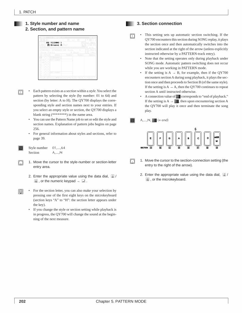
202 Chapter 5. PATTERN MODE
1. Style number and name2. Section, and pattern name
• Each pattern exists as a section within a style. You select thepattern by selecting the style (by number: 01 to 64) andsection (by letter: A to H). The QY700 displays the corre-sponding style and section names next to your entries. Ifyou select an empty style or section, the QY700 displays ablank string (********) in the name area.
• You can use the Pattern Name job to set or edit the style andsection names. Explanation of pattern jobs begins on page256.
• For general information about styles and sections, refer topage 39.
01011101 Style number 01,...,64
Section A,...,H
1. Move the cursor to the style-number or section-letterentry area.
2. Enter the appropriate value using the data dial, n/y, or the numeric keypad → e.
• For the section letter, you can also make your selection bypressing one of the first eight keys on the microkeyboard(section keys “A” to “H”: the section letter appears underthe key).
• If you change the style or section setting while playback isin progress, the QY700 will change the sound at the begin-ning of the next measure.
3. Section connection
• This setting sets up automatic section switching. If theQY700 encounters this section during SONG replay, it playsthe section once and then automatically switches into thesection indicated at the right of the arrow (unless explicitlyinstructed otherwise by a PATTERN-track entry).
• Note that the setting operates only during playback underSONG mode. Automatic pattern switching does not occurwhile you are working in PATTERN mode.
• If the setting is A → B, for example, then if the QY700encounters section A during song playback, it plays the sec-tion once and then proceeds to Section B (of the same style).If the setting is A → A, then the QY700 continues to repeatsection A until instructed otherwise.
• A connection value of corresponds to “end of playback.”If the setting is A → , then upon encountering section Athe QY700 will play it once and then terminate the songplay.
01011101 A,...,H, (= end)
1. Move the cursor to the section-connection setting (theentry to the right of the arrow).
2. Enter the appropriate value using the data dial, n/y, or the microkeyboard.
1. PATCH
E F G A B C DM
add9
SECTION A
c
B C D E F G H
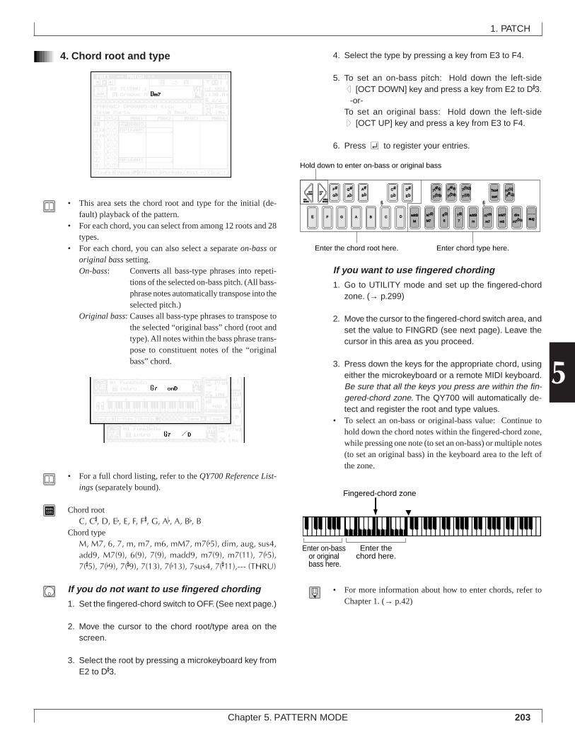
203Chapter 5. PATTERN MODE
5
4. Chord root and type
• This area sets the chord root and type for the initial (de-fault) playback of the pattern.
• For each chord, you can select from among 12 roots and 28types.
• For each chord, you can also select a separate on-bass ororiginal bass setting.On-bass: Converts all bass-type phrases into repeti-
tions of the selected on-bass pitch. (All bass-phrase notes automatically transpose into theselected pitch.)
Original bass: Causes all bass-type phrases to transpose tothe selected “original bass” chord (root andtype). All notes within the bass phrase trans-pose to constituent notes of the “originalbass” chord.
• For a full chord listing, refer to the QY700 Reference List-ings (separately bound).
01011101 Chord root
C, C#, D, Eb, E, F, F#, G, Ab, A, Bb, BChord type
M, M7, 6, 7, m, m7, m6, mM7, m7(b5), dim, aug, sus4,add9, M7(9), 6(9), 7(9), madd9, m7(9), m7(11), 7(b5),7(#5), 7(b9), 7(#9), 7(13), 7(b13), 7sus4, 7(#11),--- (THRU)
If you do not want to use fingered chording
1. Set the fingered-chord switch to OFF. (See next page.)
2. Move the cursor to the chord root/type area on thescreen.
3. Select the root by pressing a microkeyboard key fromE2 to D#3.
4. Select the type by pressing a key from E3 to F4.
5. To set an on-bass pitch: Hold down the left-sided [OCT DOWN] key and press a key from E2 to D#3.
-or-To set an original bass: Hold down the left-sideu [OCT UP] key and press a key from E3 to F4.
6. Press e to register your entries.
If you want to use fingered chording
1. Go to UTILITY mode and set up the fingered-chordzone. (→ p.299)
2. Move the cursor to the fingered-chord switch area, andset the value to FINGRD (see next page). Leave thecursor in this area as you proceed.
3. Press down the keys for the appropriate chord, usingeither the microkeyboard or a remote MIDI keyboard.Be sure that all the keys you press are within the fin-gered-chord zone. The QY700 will automatically de-tect and register the root and type values.
• To select an on-bass or original-bass value: Continue tohold down the chord notes within the fingered-chord zone,while pressing one note (to set an on-bass) or multiple notes(to set an original bass) in the keyboard area to the left ofthe zone.
• For more information about how to enter chords, refer toChapter 1. (→ p.42)
1. PATCH
F#
E F G A B C DM
add9
M7
add9
m
mM7
m6
c
C# D#7(#5)
7(b5)
7(#9) 7sus4
sus4Gb Db Eb 7(b9)
m7(b5)
M7(9)
6
6(9)
7
7(9) m7(9)
m7
dimaug
7(b13)
7(13) 7(#11)m7(11)
c
G#
AbA#
Bb
Enter the chord root here.
Hold down to enter on-bass or original bass
Enter chord type here.
OCTDOWN
OCTUP
ONBASS
ORGBASS
Enter the chord here.
Fingered-chord zone
Enter on-bass or original bass here.
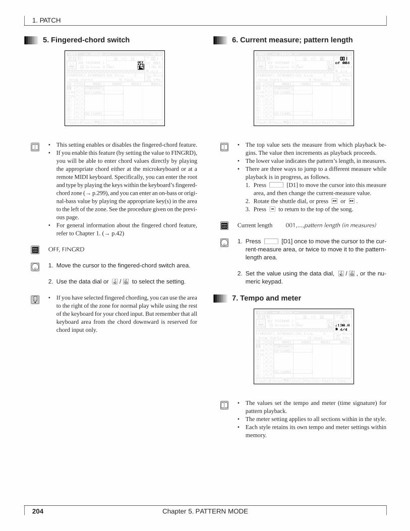
204 Chapter 5. PATTERN MODE
5. Fingered-chord switch
• This setting enables or disables the fingered-chord feature.• If you enable this feature (by setting the value to FINGRD),
you will be able to enter chord values directly by playingthe appropriate chord either at the microkeyboard or at aremote MIDI keyboard. Specifically, you can enter the rootand type by playing the keys within the keyboard’s fingered-chord zone (→ p.299), and you can enter an on-bass or origi-nal-bass value by playing the appropriate key(s) in the areato the left of the zone. See the procedure given on the previ-ous page.
• For general information about the fingered chord feature,refer to Chapter 1. (→ p.42)
01011101 OFF, FINGRD
1. Move the cursor to the fingered-chord switch area.
2. Use the data dial or n/y to select the setting.
• If you have selected fingered chording, you can use the areato the right of the zone for normal play while using the restof the keyboard for your chord input. But remember that allkeyboard area from the chord downward is reserved forchord input only.
6. Current measure; pattern length
• The top value sets the measure from which playback be-gins. The value then increments as playback proceeds.
• The lower value indicates the pattern’s length, in measures.• There are three ways to jump to a different measure while
playback is in progress, as follows.1. Press d [D1] to move the cursor into this measure
area, and then change the current-measure value.2. Rotate the shuttle dial, or press r or f.3. Press t to return to the top of the song.
01011101 Current length 001,...,pattern length (in measures)
1. Press d [D1] once to move the cursor to the cur-rent-measure area, or twice to move it to the pattern-length area.
2. Set the value using the data dial, n/y, or the nu-meric keypad.
7. Tempo and meter
• The values set the tempo and meter (time signature) forpattern playback.
• The meter setting applies to all sections within in the style.• Each style retains its own tempo and meter settings within
memory.
1. PATCH
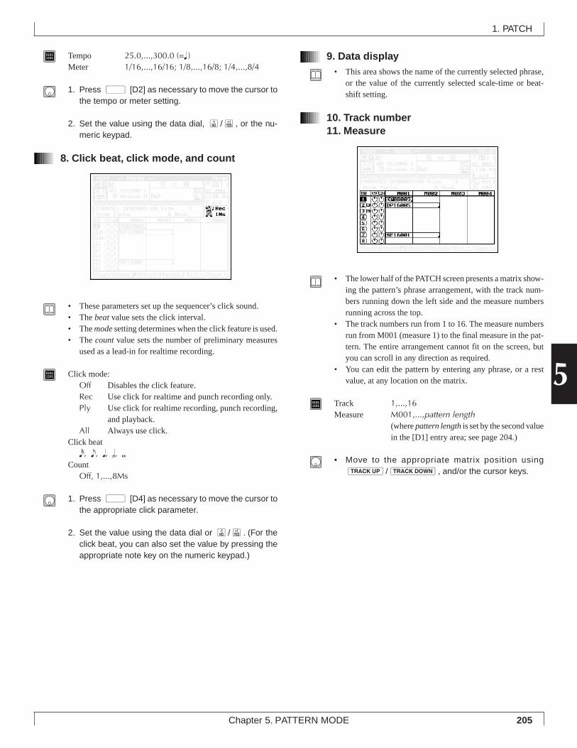
205Chapter 5. PATTERN MODE
5
01011101 Tempo 25.0,...,300.0 (=q )
Meter 1/16,...,16/16; 1/8,...,16/8; 1/4,...,8/4
1. Press d [D2] as necessary to move the cursor tothe tempo or meter setting.
2. Set the value using the data dial, n/y, or the nu-meric keypad.
8. Click beat, click mode, and count
• These parameters set up the sequencer’s click sound.• The beat value sets the click interval.• The mode setting determines when the click feature is used.• The count value sets the number of preliminary measures
used as a lead-in for realtime recording.
01011101 Click mode:
Off Disables the click feature.Rec Use click for realtime and punch recording only.Ply Use click for realtime recording, punch recording,
and playback.All Always use click.
Click beatx, e, q, h, wCount
Off, 1,...,8Ms
1. Press d [D4] as necessary to move the cursor tothe appropriate click parameter.
2. Set the value using the data dial or n/y. (For theclick beat, you can also set the value by pressing theappropriate note key on the numeric keypad.)
9. Data display• This area shows the name of the currently selected phrase,
or the value of the currently selected scale-time or beat-shift setting.
10. Track number11. Measure
• The lower half of the PATCH screen presents a matrix show-ing the pattern’s phrase arrangement, with the track num-bers running down the left side and the measure numbersrunning across the top.
• The track numbers run from 1 to 16. The measure numbersrun from M001 (measure 1) to the final measure in the pat-tern. The entire arrangement cannot fit on the screen, butyou can scroll in any direction as required.
• You can edit the pattern by entering any phrase, or a restvalue, at any location on the matrix.
01011101 Track 1,...,16
Measure M001,...,pattern length(where pattern length is set by the second valuein the [D1] entry area; see page 204.)
• Move to the appropriate matrix position usingu/d, and/or the cursor keys.
1. PATCH
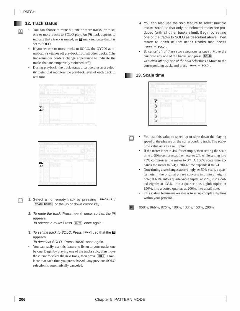
206 Chapter 5. PATTERN MODE
12. Track status• You can choose to mute out one or more tracks, or to set
one or more tracks to SOLO play. An mark appears toindicate that a track is muted; an mark indicates that it isset to SOLO.
• If you set one or more tracks to SOLO, the QY700 auto-matically switches off playback from all other tracks. (Thetrack-number borders change appearance to indicate thetracks that are temporarily switched off.)
• During playback, the track-status area operates as a veloc-ity meter that monitors the playback level of each track inreal time.
1. Select a non-empty track by pressing u/d or the up or down cursor key.
2. To mute the track: Press m once, so that the appears.To release a mute: Press m once again.
3. To set the track to SOLO: Press s, so that the appears.To deselect SOLO: Press s once again.
• You can easily use this feature to listen to your tracks oneby one. Begin by playing one of the tracks solo, then movethe cursor to select the next track, then press s again.Note that each time you press s, any previous SOLOselection is automatically canceled.
4. You can also use the solo feature to select multipletracks “solo”, so that only the selected tracks are pro-duced (with all other tracks silent). Begin by settingone of the tracks to SOLO as described above. Thenmove to each of the other tracks and presss+s.
• To cancel all of these solo selections at once : Move thecursor to any one of the tracks, and press s.To switch off only one of the solo selections : Move to thecorresponding track, and press s+s.
13. Scale time
• You use this value to speed up or slow down the playingspeed of the phrases on the corresponding track. The scale-time value acts as a multiplier.
• If the meter is set to 4/4, for example, then setting the scaletime to 50% compresses the meter to 2/4, while setting it to75% compresses the meter to 3/4. A 150% scale time ex-pands the meter to 6/4; a 200% time expands it to 8/4.
• Note timing also changes accordingly. At 50% scale, a quar-ter note in the original phrase converts into into an eighthnote; at 66%, into a quarter-note triplet; at 75%, into a dot-ted eighth; at 133%, into a quarter plus eighth-triplet; at150%, into a dotted quarter; at 200%, into a half note.
• This scaling feature makes it easy to set up complex rhythmswithin your patterns.
01011101 050%, 066%, 075%, 100%, 133%, 150%, 200%
1. PATCH
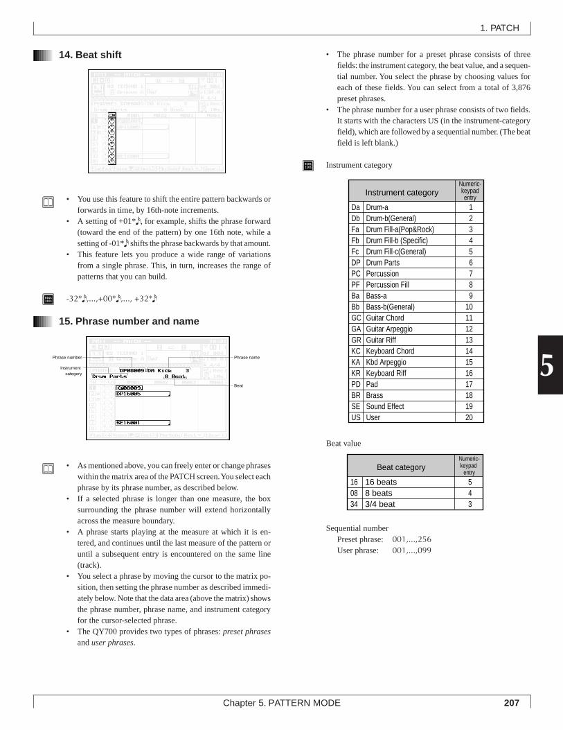
207Chapter 5. PATTERN MODE
5
14. Beat shift
• You use this feature to shift the entire pattern backwards orforwards in time, by 16th-note increments.
• A setting of +01*x, for example, shifts the phrase forward(toward the end of the pattern) by one 16th note, while asetting of -01*x shifts the phrase backwards by that amount.
• This feature lets you produce a wide range of variationsfrom a single phrase. This, in turn, increases the range ofpatterns that you can build.
01011101 -32*x,...,+00*x,..., +32*x
15. Phrase number and name
• As mentioned above, you can freely enter or change phraseswithin the matrix area of the PATCH screen. You select eachphrase by its phrase number, as described below.
• If a selected phrase is longer than one measure, the boxsurrounding the phrase number will extend horizontallyacross the measure boundary.
• A phrase starts playing at the measure at which it is en-tered, and continues until the last measure of the pattern oruntil a subsequent entry is encountered on the same line(track).
• You select a phrase by moving the cursor to the matrix po-sition, then setting the phrase number as described immedi-ately below. Note that the data area (above the matrix) showsthe phrase number, phrase name, and instrument categoryfor the cursor-selected phrase.
• The QY700 provides two types of phrases: preset phrasesand user phrases.
• The phrase number for a preset phrase consists of threefields: the instrument category, the beat value, and a sequen-tial number. You select the phrase by choosing values foreach of these fields. You can select from a total of 3,876preset phrases.
• The phrase number for a user phrase consists of two fields.It starts with the characters US (in the instrument-categoryfield), which are followed by a sequential number. (The beatfield is left blank.)
01011101 Instrument category
Beat value
Sequential numberPreset phrase: 001,...,256User phrase: 001,...,099
1. PATCH
Instrument category
Da Drum-a 1Db Drum-b(General) 2Fa Drum Fill-a(Pop&Rock) 3Fb Drum Fill-b (Specific) 4Fc Drum Fill-c(General) 5DP Drum Parts 6PC Percussion 7PF Percussion Fill 8Ba Bass-a 9Bb Bass-b(General) 10GC Guitar Chord 11GA Guitar Arpeggio 12GR Guitar Riff 13KC Keyboard Chord 14KA Kbd Arpeggio 15KR Keyboard Riff 16PD Pad 17BR Brass 18SE Sound Effect 19US User 20
Numeric-keypadentry
Beat category
16 16 beats 508 8 beats 434 3/4 beat 3
Numeric-keypad
entry
Phrase number
Instrument category
Phrase name
Beat
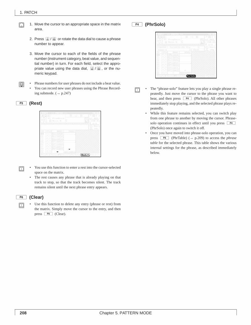
208 Chapter 5. PATTERN MODE
1. Move the cursor to an appropriate space in the matrixarea.
2. Press n/y or rotate the data dial to cause a phrasenumber to appear.
3. Move the cursor to each of the fields of the phrasenumber (instrument category, beat value, and sequen-tial number) in turn. For each field, select the appro-priate value using the data dial, n/y, or the nu-meric keypad.
• Phrase numbers for user phrases do not include a beat value.• You can record new user phrases using the Phrase Record-
ing submode. (→ p.247)
5 (Rest)
• You use this function to enter a rest into the cursor-selectedspace on the matrix.
• The rest causes any phrase that is already playing on thattrack to stop, so that the track becomes silent. The trackremains silent until the next phrase entry appears.
6 (Clear)• Use this function to delete any entry (phrase or rest) from
the matrix. Simply move the cursor to the entry, and thenpress 6 (Clear).
4 (PhrSolo)
• The “phrase-solo” feature lets you play a single phrase re-peatedly. Just move the cursor to the phrase you want tohear, and then press 4 (PhrSolo). All other phrasesimmediately stop playing, and the selected phrase plays re-peatedly.
• While this feature remains selected, you can switch playfrom one phrase to another by moving the cursor. Phrase-solo operation continues in effect until you press 4
(PhrSolo) once again to switch it off.• Once you have moved into phrase-solo operation, you can
press 6 (PhrTable) (→ p.209) to access the phrasetable for the selected phrase. This table shows the variousinternal settings for the phrase, as described immediatelybelow.
1. PATCH
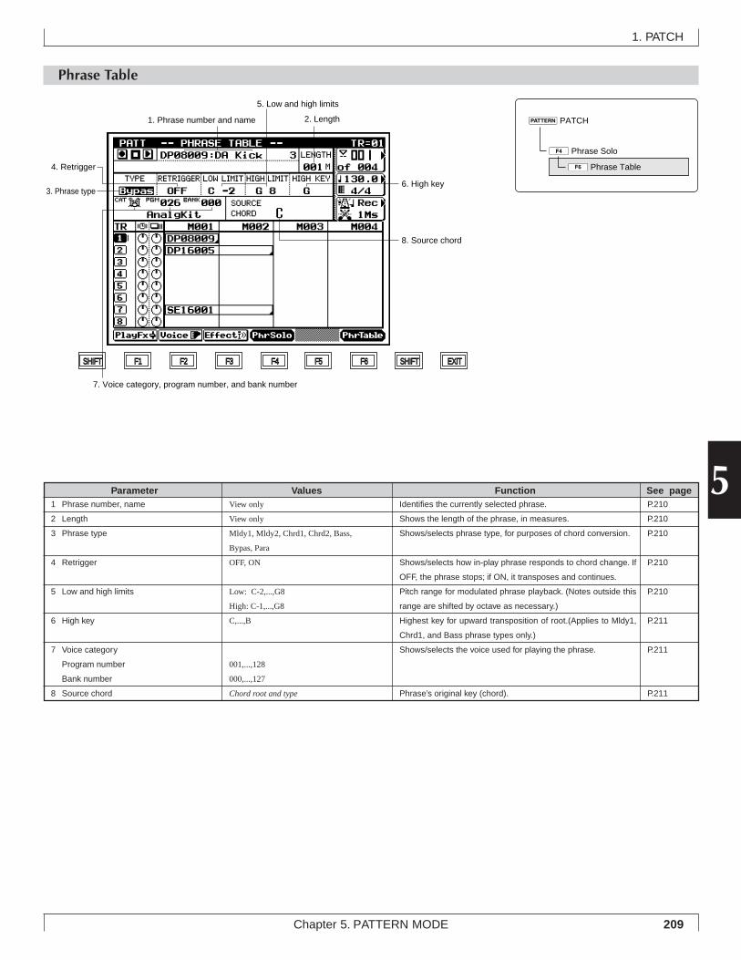
209Chapter 5. PATTERN MODE
5
Phrase Table
1. PATCH
Identifies the currently selected phrase.
Shows the length of the phrase, in measures.
Shows/selects phrase type, for purposes of chord conversion.
Shows/selects how in-play phrase responds to chord change. If
OFF, the phrase stops; if ON, it transposes and continues.
Pitch range for modulated phrase playback. (Notes outside this
range are shifted by octave as necessary.)
Highest key for upward transposition of root.(Applies to Mldy1,
Chrd1, and Bass phrase types only.)
Shows/selects the voice used for playing the phrase.
Phrase’s original key (chord).
View only
View only
Mldy1, Mldy2, Chrd1, Chrd2, Bass,
Bypas, Para
OFF, ON
Low: C-2,...,G8
High: C-1,...,G8
C,...,B
001,...,128
000,...,127
Chord root and type
1 Phrase number, name
2 Length
3 Phrase type
4 Retrigger
5 Low and high limits
6 High key
7 Voice category
Program number
Bank number
8 Source chord
Parameter Values Function See pageP.210
P.210
P.210
P.210
P.210
P.211
P.211
P.211
4Phrase Solo
pPATCH
6Phrase Table
SHIFT F1 F2 F3 F4 F5 F6 SHIFT EXIT
3. Phrase type
4. Retrigger
2. Length1. Phrase number and name
5. Low and high limits
6. High key
8. Source chord
7. Voice category, program number, and bank number
210 Chapter 5. PATTERN MODE
• You use the phrase table to access the parameters for thecurrently selected phrase.
• Note that it is not possible to edit the parameter values forpreset phrases. But you are free to edit the values on youruser phrases.
• If you wish to change the values for a preset phrase, youcan copy it into a user phrase, and then edit the copy.
1. Select the phrase at the PATCH screen. (→ p.208)
2. Press 4 (PhrSolo) once, to set the PATCH screeninto “phrase solo” mode.
3. Press 6 (PhrTable) to move to the Phrase Tablescreen.
4. If you have selected a user phrase: Move the cursor toeach of the settings you want to change, and enter theappropriate value using n/y or the data dial.
5. When you have finished, press e to return to the“phrase solo” screen.
6. When you are ready, press e again to release“phrase solo” and resume normal PATCH-screen op-eration.
1. Phrase number and name• These values identify the currently selected phrase.• You can use the Phrase Name job to set or change the names
for your user phrases. (→ p.279)
2. Phrase length• This value shows the phrase’s length, in measures.• It is not possible to change this value for existing phrases.
Before recording a new user phrase, however, you can setthe length value from the Recording Standby screen. (→p.249)
3. Phrase type
• The TYPE value selects the kind of chord conversion usedwhen modulating (transposing) the phrase. Different TYPEsettings result in different conversion results, as follows.
• The “Melody” types (Mdly1, Mldy2) generate relativelyslight, subtle changes in the playback sound.
• The “Chord” types (Chrd1, Chrd2) generate relatively largechanges in the playback sound.
• For Mldy1 and Chrd1 transpositions, the QY700 first con-verts the original phrase line according to the chord type,and then transposes according to the chord root. For Mldy2and Chrd2 transpositions, the QY700 attempts to remaincloser to the original sound, so that the chord change is some-what smoother.
• The Bass type is used for bass phrases. For these phrases,the QY700 always produces the root note at the start of anychord change. In addition, transposition is always accord-ing to the target chord’s on-bass or original-bass setting (ifany).
• The Bypas (Bypass) setting disables all phrase transposi-tion – the phrase always bypasses the conversion processand plays out in its original sound. (Note that drum andpercussion voices are always Bypas type.)
• The Para (parallel) type transposes by root only; the chordtype is ignored. This is useful for phrases that contain im-plicit internal chord changes, since chord type conversionin this case may produce unpredictable or clashing results.
01011101 Mldy1, Mldy2, Chrd1, Chrd2, Bass, Bypas, Para
4. Retrigger• This setting determines how the phrase responds to chord
changes that occur while the phrase is already playing. Ifthe setting is OFF, the phrase switches off when the chordchange occurs. If ON, the QY700 transposes the phrase (inaccordance with the chord-conversion parameters) and con-tinues the playback.
01011101 OFF, ON
5. Low and high limits• These values select the highest and lowest notes that can be
used for replay of the transposed phrase. If transpositionproduces a note that is outside the limit, the QY700 shiftsthe note (by octave) to bring it into range.
01011101 Low limit C-2,...,G8
High limit C-1,...,G8
1. PATCH
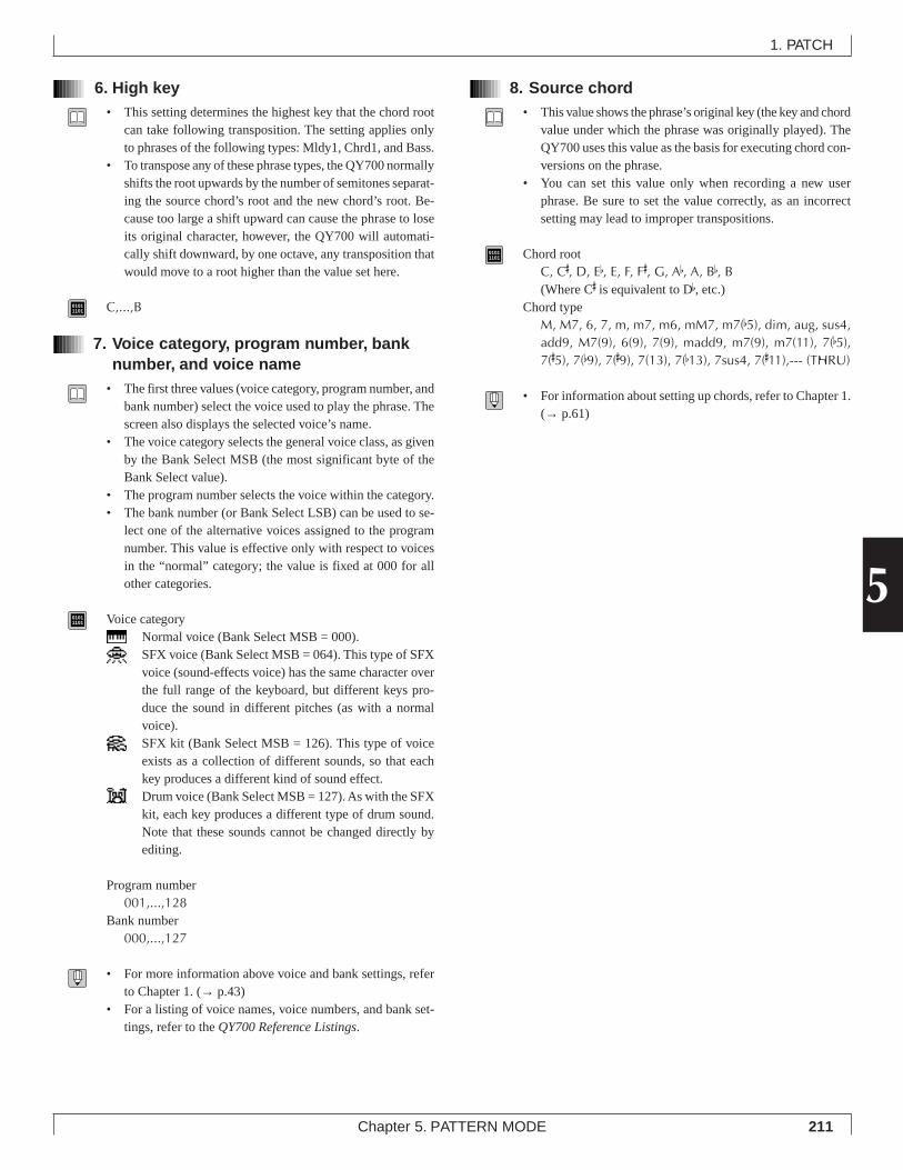
211Chapter 5. PATTERN MODE
5
6. High key• This setting determines the highest key that the chord root
can take following transposition. The setting applies onlyto phrases of the following types: Mldy1, Chrd1, and Bass.
• To transpose any of these phrase types, the QY700 normallyshifts the root upwards by the number of semitones separat-ing the source chord’s root and the new chord’s root. Be-cause too large a shift upward can cause the phrase to loseits original character, however, the QY700 will automati-cally shift downward, by one octave, any transposition thatwould move to a root higher than the value set here.
01011101 C,...,B
7. Voice category, program number, banknumber, and voice name
• The first three values (voice category, program number, andbank number) select the voice used to play the phrase. Thescreen also displays the selected voice’s name.
• The voice category selects the general voice class, as givenby the Bank Select MSB (the most significant byte of theBank Select value).
• The program number selects the voice within the category.• The bank number (or Bank Select LSB) can be used to se-
lect one of the alternative voices assigned to the programnumber. This value is effective only with respect to voicesin the “normal” category; the value is fixed at 000 for allother categories.
01011101 Voice category
Normal voice (Bank Select MSB = 000).SFX voice (Bank Select MSB = 064). This type of SFXvoice (sound-effects voice) has the same character overthe full range of the keyboard, but different keys pro-duce the sound in different pitches (as with a normalvoice).SFX kit (Bank Select MSB = 126). This type of voiceexists as a collection of different sounds, so that eachkey produces a different kind of sound effect.Drum voice (Bank Select MSB = 127). As with the SFXkit, each key produces a different type of drum sound.Note that these sounds cannot be changed directly byediting.
Program number001,...,128
Bank number000,...,127
• For more information above voice and bank settings, referto Chapter 1. (→ p.43)
• For a listing of voice names, voice numbers, and bank set-tings, refer to the QY700 Reference Listings.
8. Source chord• This value shows the phrase’s original key (the key and chord
value under which the phrase was originally played). TheQY700 uses this value as the basis for executing chord con-versions on the phrase.
• You can set this value only when recording a new userphrase. Be sure to set the value correctly, as an incorrectsetting may lead to improper transpositions.
01011101 Chord root
C, C#, D, Eb, E, F, F#, G, Ab, A, Bb, B(Where C# is equivalent to Db, etc.)
Chord typeM, M7, 6, 7, m, m7, m6, mM7, m7(b5), dim, aug, sus4,add9, M7(9), 6(9), 7(9), madd9, m7(9), m7(11), 7(b5),7(#5), 7(b9), 7(#9), 7(13), 7(b13), 7sus4, 7(#11),--- (THRU)
• For information about setting up chords, refer to Chapter 1.(→ p.61)
1. PATCH
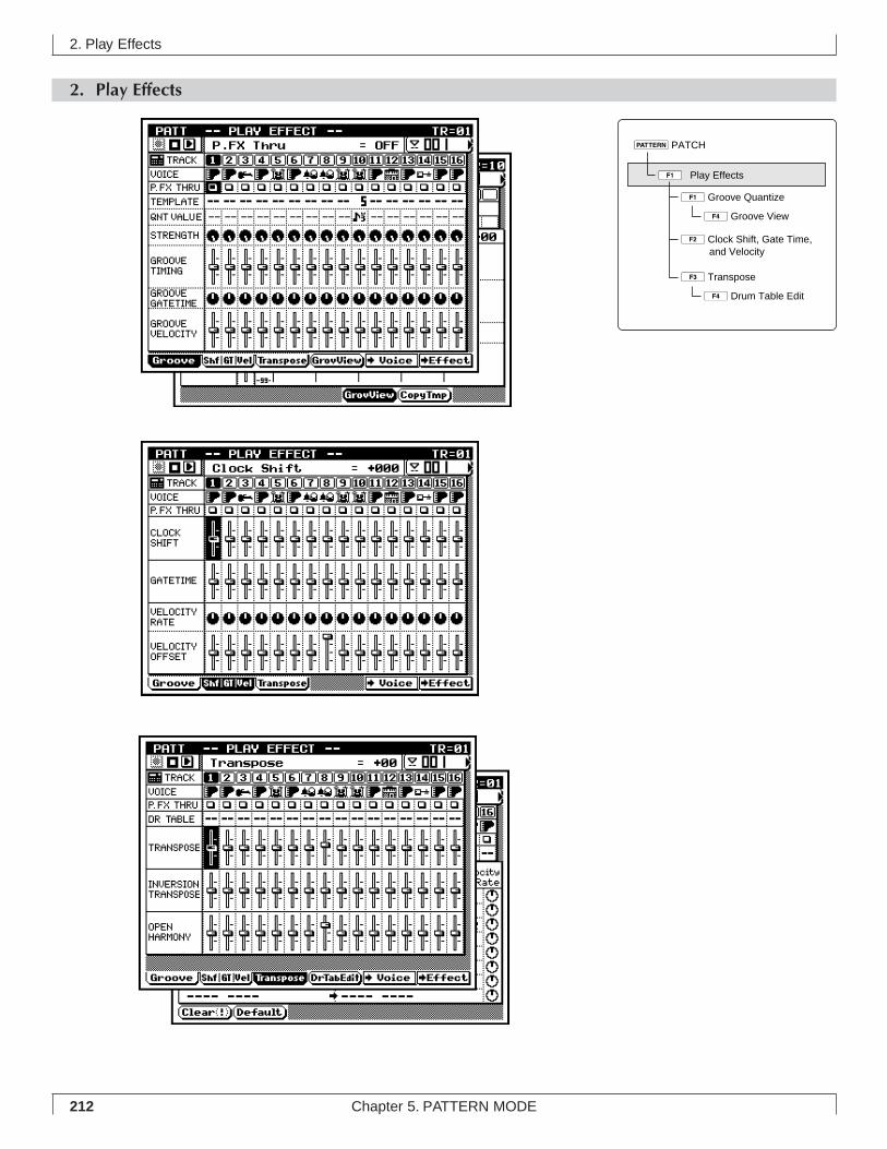
212 Chapter 5. PATTERN MODE
2. Play Effects
2. Play Effects
1Groove Quantize
2Clock Shift, Gate Time, and Velocity
1ÊPlay Effects
4Groove View
3Transpose
4Drum Table Edit
pPATCH
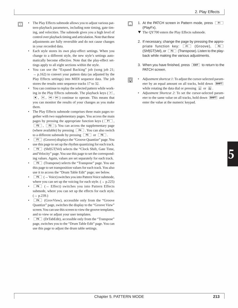
213Chapter 5. PATTERN MODE
5
• The Play Effects submode allows you to adjust various pat-tern-playback parameters, including note timing, gate tim-ing, and velocities. The submode gives you a high level ofcontrol over playback timing and articulation. Note that theseadjustments are fully reversible and do not cause changesin your recorded data.
• Each style stores its own play-effect settings. When youchange to a different style, the new style’s settings auto-matically become effective. Note that the play-effect set-tings apply to all eight sections within the style.
• You can use the “Expand Backing” job (song job 21;→ p.162) to convert your pattern data (as adjusted by thePlay Effects settings) into MIDI sequence data. The jobstores the results onto sequence tracks 17 to 32.
• You can continue to replay the selected pattern while work-ing in the Play Effects submode. The playback keys (p,s, t, r/f) continue to operate. This means thatyou can monitor the results of your changes as you makethem.
• The Play Effects submode comprises three main pages to-gether with two supplementary pages. You access the mainpages by pressing the appropriate function keys (1,2, 3). You can access the supplementary page(where available) by pressing 4. You can also switchto a different submode by pressing 5 or 6.
• 1 (Groove) displays the “Groove Quantize” page. Youuse this page to set up the rhythm quantizing for each track.
• 2 (Shf|GT|Vel) selects the “Clock Shift, Gate Time,and Velocity” page. You use this page to set the correspond-ing values. Again, values are set separately for each track.
• 3 (Transpose) selects the “Transpose” page. You usethis page to set transposition values for each track. You alsouse it to access the “Drum Table Edit” page; see below.
• 5 (→ Voice) switches you into Pattern Voice submode,where you can set up the voicing for each style. (→ p.225)
• 6 (→ Effect) switches you into Pattern Effectssubmode, where you can set up the effects for each style.(→ p.239.)
• 4 (GrovView), accessible only from the “GrooveQuantize” page, switches the display to the “Groove View”screen. You can use this screen to view the groove templates,and to view or adjust your user templates.
• 4 (DrTabEdit), accessible only from the “Transpose”page, switches you to the “Drum Table Edit” page. You canuse this page to adjust the drum table settings.
1. At the PATCH screen in Pattern mode, press 1(PlayFx).
▼ The QY700 enters the Play Effects submode.
2. If necessary, change the page by pressing the appro-priate function key: 1 (Groove), 2
(Shf|GT|Vel), or 3 (Transpose). Listen to the play-back while making the various adjustments.
3. When you have finished, press e to return to thePATCH screen.
• Adjustment shortcut 1: To adjust the cursor-selected param-eter by an equal amount on all tracks, hold down s
while rotating the data dial or pressing n or y.• Adjustment Shortcut 2: To set the cursor-selected param-
eter to the same value on all tracks, hold down s andenter the value at the numeric keypad.
2. Play Effects
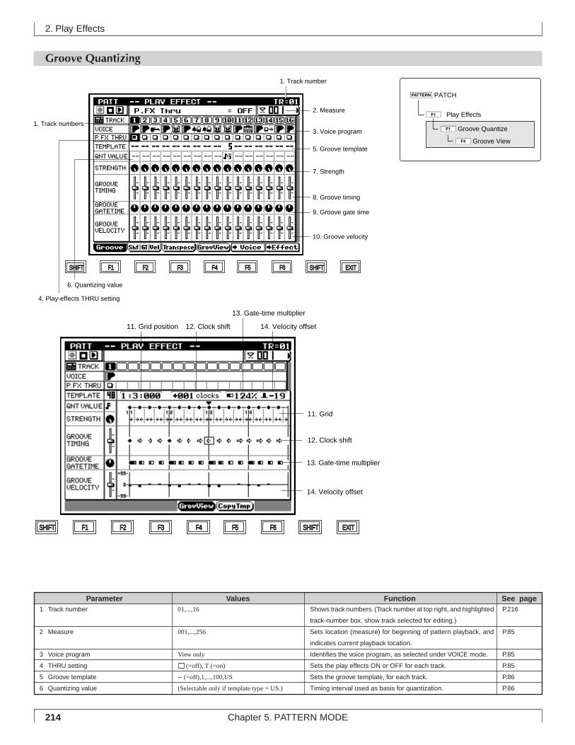
214 Chapter 5. PATTERN MODE
2. Play Effects
Groove Quantizing
Shows track numbers. (Track number at top right, and highlighted
track-number box, show track selected for editing.)
Sets location (measure) for beginning of pattern playback, and
indicates current playback location.
Identifies the voice program, as selected under VOICE mode.
Sets the play effects ON or OFF for each track.
Sets the groove template, for each track.
Timing interval used as basis for quantization.
01,...,16
001,...,256
View only
(=off), T (=on)
-- (=off),1,...,100,US
(Selectable only if template type = US.)
1 Track number
2 Measure
3 Voice program
4 THRU setting
5 Groove template
6 Quantizing value
Parameter Values Function See pageP.216
P.85
P.85
P.85
P.86
P.86
SHIFT F1 F2 F3 F4 F5 F6 SHIFT EXIT
2. Measure
1. Track number
1. Track numbers
10. Groove velocity
9. Groove gate time
8. Groove timing
7. Strength
6. Quantizing value
5. Groove template
4. Play-effects THRU setting
3. Voice program
11. Grid
12. Clock shift
13. Gate-time multiplier
14. Velocity offset
SHIFT F1 F2 F3 F4 F5 F6 SHIFT EXIT
11. Grid position 12. Clock shift
13. Gate-time multiplier
14. Velocity offset
1ÊPlay Effects
pPATCH
1Groove Quantize
4Groove View
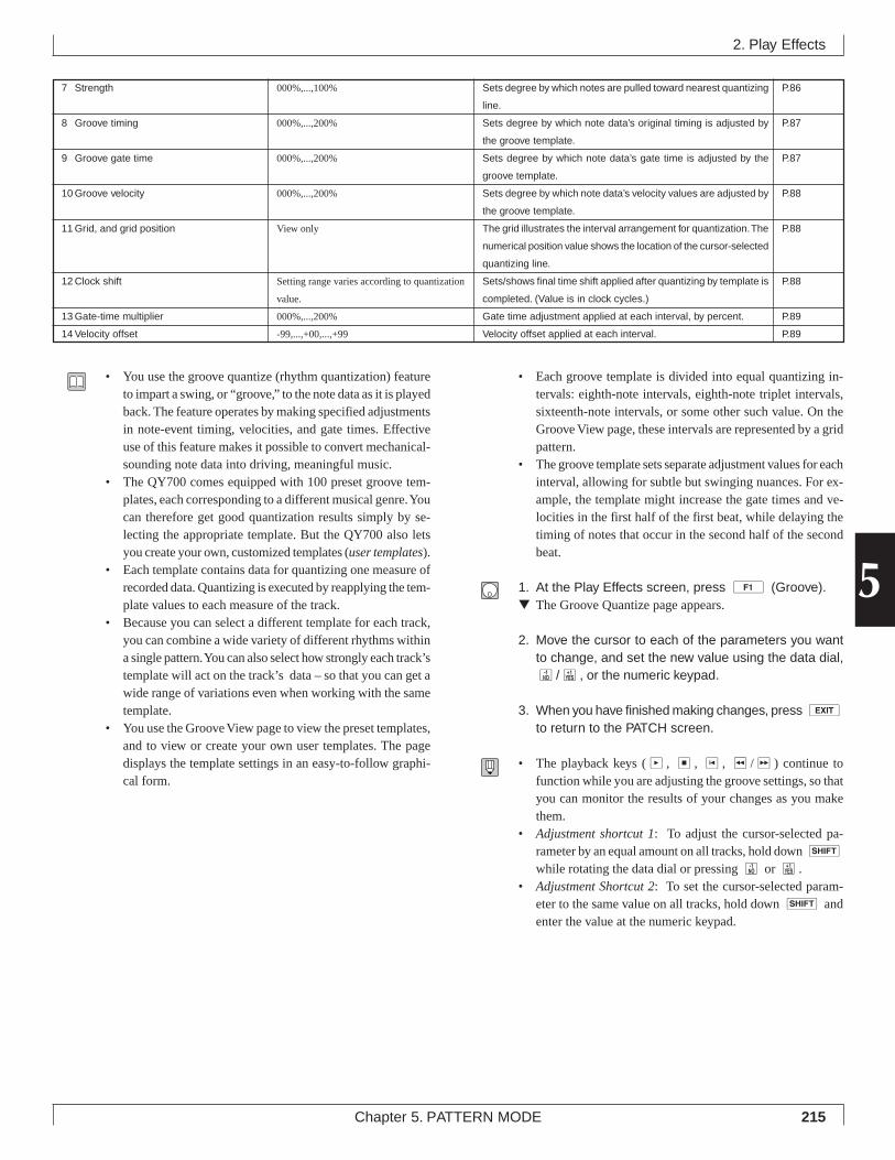
215Chapter 5. PATTERN MODE
5
2. Play Effects
Sets degree by which notes are pulled toward nearest quantizing
line.
Sets degree by which note data’s original timing is adjusted by
the groove template.
Sets degree by which note data’s gate time is adjusted by the
groove template.
Sets degree by which note data’s velocity values are adjusted by
the groove template.
The grid illustrates the interval arrangement for quantization. The
numerical position value shows the location of the cursor-selected
quantizing line.
Sets/shows final time shift applied after quantizing by template is
completed. (Value is in clock cycles.)
Gate time adjustment applied at each interval, by percent.
Velocity offset applied at each interval.
000%,...,100%
000%,...,200%
000%,...,200%
000%,...,200%
View only
Setting range varies according to quantization
value.
000%,...,200%
-99,...,+00,...,+99
7 Strength
8 Groove timing
9 Groove gate time
10 Groove velocity
11 Grid, and grid position
12 Clock shift
13 Gate-time multiplier
14 Velocity offset
P.86
P.87
P.87
P.88
P.88
P.88
P.89
P.89
• You use the groove quantize (rhythm quantization) featureto impart a swing, or “groove,” to the note data as it is playedback. The feature operates by making specified adjustmentsin note-event timing, velocities, and gate times. Effectiveuse of this feature makes it possible to convert mechanical-sounding note data into driving, meaningful music.
• The QY700 comes equipped with 100 preset groove tem-plates, each corresponding to a different musical genre. Youcan therefore get good quantization results simply by se-lecting the appropriate template. But the QY700 also letsyou create your own, customized templates (user templates).
• Each template contains data for quantizing one measure ofrecorded data. Quantizing is executed by reapplying the tem-plate values to each measure of the track.
• Because you can select a different template for each track,you can combine a wide variety of different rhythms withina single pattern. You can also select how strongly each track’stemplate will act on the track’s data – so that you can get awide range of variations even when working with the sametemplate.
• You use the Groove View page to view the preset templates,and to view or create your own user templates. The pagedisplays the template settings in an easy-to-follow graphi-cal form.
• Each groove template is divided into equal quantizing in-tervals: eighth-note intervals, eighth-note triplet intervals,sixteenth-note intervals, or some other such value. On theGroove View page, these intervals are represented by a gridpattern.
• The groove template sets separate adjustment values for eachinterval, allowing for subtle but swinging nuances. For ex-ample, the template might increase the gate times and ve-locities in the first half of the first beat, while delaying thetiming of notes that occur in the second half of the secondbeat.
1. At the Play Effects screen, press 1 (Groove).▼ The Groove Quantize page appears.
2. Move the cursor to each of the parameters you wantto change, and set the new value using the data dial,n/y, or the numeric keypad.
3. When you have finished making changes, press eto return to the PATCH screen.
• The playback keys (p, s, t, r/f) continue tofunction while you are adjusting the groove settings, so thatyou can monitor the results of your changes as you makethem.
• Adjustment shortcut 1: To adjust the cursor-selected pa-rameter by an equal amount on all tracks, hold down s
while rotating the data dial or pressing n or y.• Adjustment Shortcut 2: To set the cursor-selected param-
eter to the same value on all tracks, hold down s andenter the value at the numeric keypad.
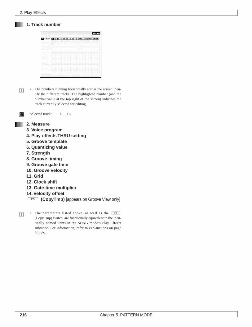
216 Chapter 5. PATTERN MODE
1. Track number
• The numbers running horizontally across the screen iden-tify the different tracks. The highlighted number (and thenumber value at the top right of the screen) indicates thetrack currently selected for editing.
01011101 Selected track: 1,...,16
2. Measure3. Voice program4. Play-effects THRU setting5. Groove template6. Quantizing value7. Strength8. Groove timing9. Groove gate time10. Groove velocity11. Grid12. Clock shift13. Gate-time multiplier14. Velocity offset5 (CopyTmp) [appears on Groove View only]
• The parameters listed above, as well as the 5
(CopyTmp) switch, are functionally equivalent to the iden-tically named items in the SONG mode’s Play Effectssubmode. For information, refer to explanations on page85 - 89.
2. Play Effects
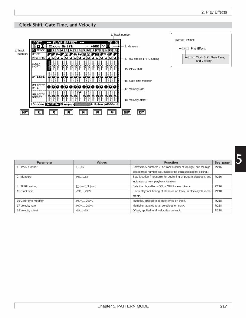
217Chapter 5. PATTERN MODE
5
2. Play Effects
Clock Shift, Gate Time, and Velocity
Shows track numbers. (The track number at top right, and the high-
lighted track-number box, indicate the track selected for editing.)
Sets location (measure) for beginning of pattern playback, and
indicates current playback location
Sets the play effects ON or OFF for each track.
Shifts playback timing of all notes on track, in clock-cycle incre-
ments.
Mutiplier, applied to all gate times on track.
Multiplier, applied to all velocities on track.
Offset, applied to all velocities on track.
1,...,16
001,...,256
(=off), T (=on)
-999,...,+999
000%,...,200%
000%,...,200%
-99,...,+99
1 Track number
2 Measure
4 THRU setting
15 Clock shift
16 Gate-time modifier
17 Velocity rate
18 Velocity offset
Parameter Values Function See pageP.216
P.216
P.216
P.218
P.218
P.218
P.218
18. Velocity offset
17. Velocity rate
16. Gate-time modifier
15. Clock shift
4. Play-effects THRU setting
1. Track number
1. Track numbers
2. Measure
SHIFT F1 F2 F3 F4 F5 F6 SHIFT EXIT
1ÊPlay Effects
pPATCH
2Clock Shift, Gate Time, and Velocity
218 Chapter 5. PATTERN MODE
• You use this page to set the following play-effect param-eters: clock shift, gate-time modifier, velocity rate, and ve-locity offset.
1. At the Play Effects screen, press 2 (Shf|GT|Vel).▼ The “Clock Shift, Gate Time, and Velocity” page appears.
2. Move the cursor to each of the parameters you wantto change, and set the new value using the data dial,n/y, or the numeric keypad.
3. When you have finished making changes, press eto return to the PATCH screen.
• The playback keys (p, s, t, r/f) continue tofunction while you are adjusting the settings, so that youcan monitor the results of your changes as you make them.
• Adjustment shortcut 1: To adjust the cursor-selected pa-rameter by an equal amount on all tracks, hold down s
while rotating the data dial or pressing n or y .• Adjustment Shortcut 2: To set the cursor-selected param-
eter to the same value on all tracks, hold down s andenter the value at the numeric keypad.
15. Clock shift16. Gate-time modifier17. Velocity rate18. Velocity offset
• The parameters listed above are functionally equivalent tothe identically named parameters in the SONG mode’s PlayEffects submode. Refer to Chapter 2, page 90 for details.
• For additional information about the clock shift parameter,see directly below.
• If you apply a negative clock shift value that would move anote past the beginning of the pattern, the note will sound atthe precise start of the pattern when the pattern begins itsreplay. If you set the value to -200, for instance, all noteswithin the first 200 cycles of the track will sound togetherwhen the pattern starts up.
• For second and subsequent rounds of the pattern, however,all clock-shifts are applied correctly.
2. Play Effects
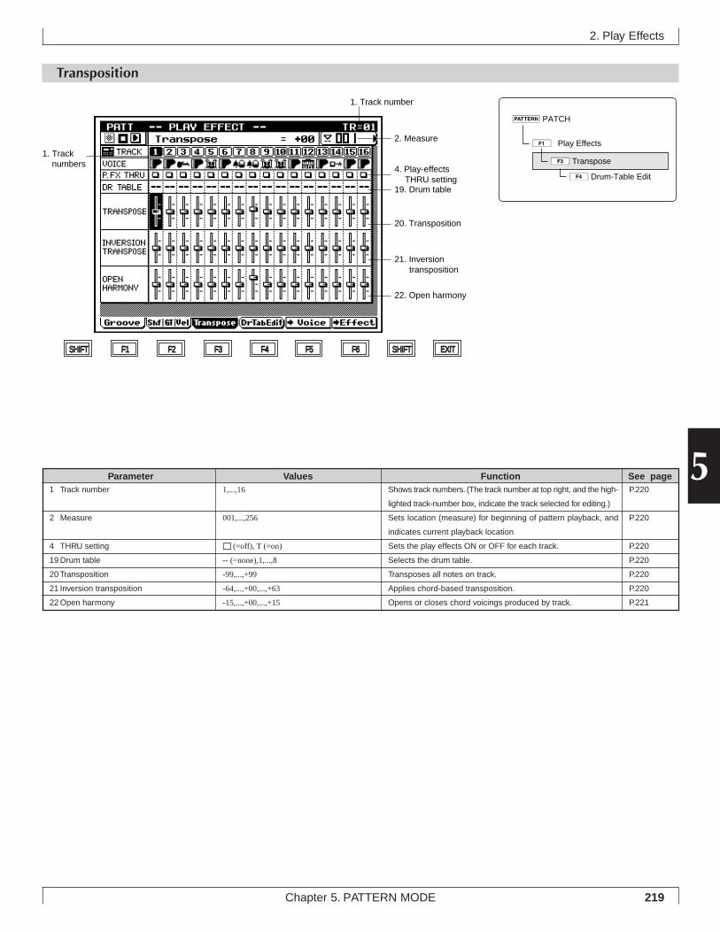
219Chapter 5. PATTERN MODE
5
2. Play Effects
Transposition
Shows track numbers. (The track number at top right, and the high-
lighted track-number box, indicate the track selected for editing.)
Sets location (measure) for beginning of pattern playback, and
indicates current playback location
Sets the play effects ON or OFF for each track.
Selects the drum table.
Transposes all notes on track.
Applies chord-based transposition.
Opens or closes chord voicings produced by track.
1,...,16
001,...,256
(=off), T (=on)
-- (=none),1,...,8
-99,...,+99
-64,...,+00,...,+63
-15,...,+00,...,+15
1 Track number
2 Measure
4 THRU setting
19 Drum table
20 Transposition
21 Inversion transposition
22 Open harmony
Parameter Values Function See pageP.220
P.220
P.220
P.220
P.220
P.220
P.221
SHIFT F1 F2 F3 F4 F5 F6 SHIFT EXIT
1. Track number
1. Track numbers
2. Measure
22. Open harmony
21. Inversion transposition
20. Transposition
19. Drum table
4. Play-effects THRU setting
1ÊPlay Effects
pPATCH
3Transpose
4Drum-Table Edit
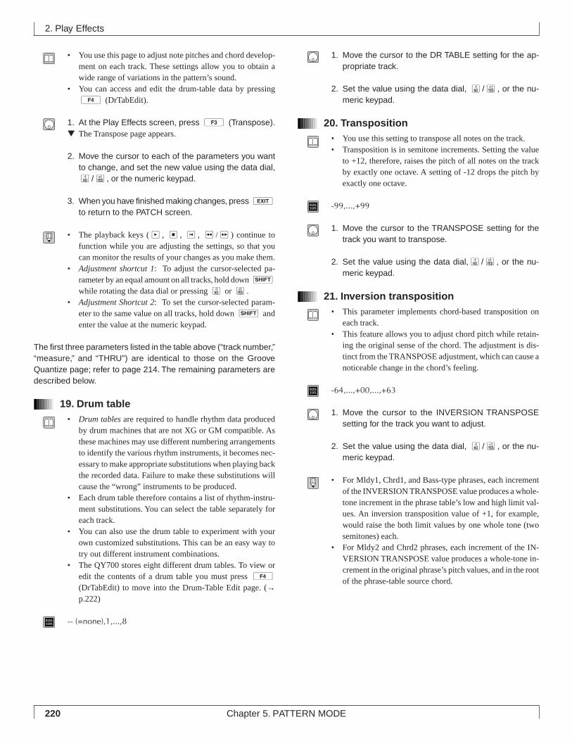
220 Chapter 5. PATTERN MODE
• You use this page to adjust note pitches and chord develop-ment on each track. These settings allow you to obtain awide range of variations in the pattern’s sound.
• You can access and edit the drum-table data by pressing4 (DrTabEdit).
1. At the Play Effects screen, press 3 (Transpose).▼ The Transpose page appears.
2. Move the cursor to each of the parameters you wantto change, and set the new value using the data dial,n/y, or the numeric keypad.
3. When you have finished making changes, press eto return to the PATCH screen.
• The playback keys (p, s, t, r/f) continue tofunction while you are adjusting the settings, so that youcan monitor the results of your changes as you make them.
• Adjustment shortcut 1: To adjust the cursor-selected pa-rameter by an equal amount on all tracks, hold down s
while rotating the data dial or pressing n or y.• Adjustment Shortcut 2: To set the cursor-selected param-
eter to the same value on all tracks, hold down s andenter the value at the numeric keypad.
The first three parameters listed in the table above (“track number,”“measure,” and “THRU”) are identical to those on the GrooveQuantize page; refer to page 214. The remaining parameters aredescribed below.
19. Drum table• Drum tables are required to handle rhythm data produced
by drum machines that are not XG or GM compatible. Asthese machines may use different numbering arrangementsto identify the various rhythm instruments, it becomes nec-essary to make appropriate substitutions when playing backthe recorded data. Failure to make these substitutions willcause the “wrong” instruments to be produced.
• Each drum table therefore contains a list of rhythm-instru-ment substitutions. You can select the table separately foreach track.
• You can also use the drum table to experiment with yourown customized substitutions. This can be an easy way totry out different instrument combinations.
• The QY700 stores eight different drum tables. To view oredit the contents of a drum table you must press 4
(DrTabEdit) to move into the Drum-Table Edit page. (→p.222)
01011101 -- (=none),1,...,8
1. Move the cursor to the DR TABLE setting for the ap-propriate track.
2. Set the value using the data dial, n/y, or the nu-meric keypad.
20. Transposition• You use this setting to transpose all notes on the track.• Transposition is in semitone increments. Setting the value
to +12, therefore, raises the pitch of all notes on the trackby exactly one octave. A setting of -12 drops the pitch byexactly one octave.
01011101 -99,...,+99
1. Move the cursor to the TRANSPOSE setting for thetrack you want to transpose.
2. Set the value using the data dial,n/y, or the nu-meric keypad.
21. Inversion transposition• This parameter implements chord-based transposition on
each track.• This feature allows you to adjust chord pitch while retain-
ing the original sense of the chord. The adjustment is dis-tinct from the TRANSPOSE adjustment, which can cause anoticeable change in the chord’s feeling.
01011101 -64,...,+00,...,+63
1. Move the cursor to the INVERSION TRANSPOSEsetting for the track you want to adjust.
2. Set the value using the data dial, n/y, or the nu-meric keypad.
• For Mldy1, Chrd1, and Bass-type phrases, each incrementof the INVERSION TRANSPOSE value produces a whole-tone increment in the phrase table’s low and high limit val-ues. An inversion transposition value of +1, for example,would raise the both limit values by one whole tone (twosemitones) each.
• For Mldy2 and Chrd2 phrases, each increment of the IN-VERSION TRANSPOSE value produces a whole-tone in-crement in the original phrase’s pitch values, and in the rootof the phrase-table source chord.
2. Play Effects
221Chapter 5. PATTERN MODE
5
22. Open harmony• This adjustment opens or closes the chord voicings on the
track.• This feature lets you adjust chord resonance characteristics
without changing the essential character of the chords.
01011101 -15,...,+00,...,+15
1. Move the cursor to the OPEN HARMONY setting forthe track you want to adjust.
2. Set the value using the data dial, n/y, or the nu-meric keypad.
2. Play Effects
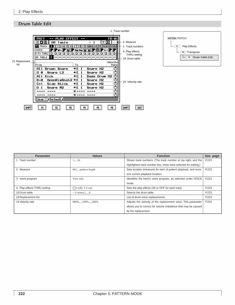
222 Chapter 5. PATTERN MODE
2. Play Effects
Drum Table Edit
Shows track numbers. (The track number at top right, and the
highlighted track-number box, show track selected for editing.)
Sets location (measure) for start of pattern playback, and moni-
tors current playback location.
Identifies the track’s voice program, as selected under VOICE
mode.
Sets the play effects ON or OFF for each track.
Selects the drum table.
List of drum-voice replacements.
Adjusts the velocity of the replacement voice. This parameter
allows you to correct for volume imbalance that may be caused
by the replacement.
1,...,16
001,...,pattern length
View only
(=off), T (=on)
-- (=none),1,...,8
000%,...,100%,...,200%
1 Track number
2 Measure
3 Voice program
4 Play-effects THRU setting
19 Drum table
23 Replacement list
24 Velocity rate
Parameter Values Function See pageP.223
P.223
P.223
P.223
P.223
P.223
P.223
1ÊPlay Effects
pPATCH
3Transpose
4Drum-Table Edit
SHIFT F1 F2 F3 F4 F5 F6 SHIFT EXIT
1. Track number
1. Track numbers
2. Measure
4. Play-effects THRU setting
19. Drum table
24. Velocity rate
23. Replacement list
223Chapter 5. PATTERN MODE
5
• You use this page to edit the selected drum table.• Drum tables are required to handle rhythm data produced
by drum machines that are not XG or GM compatible. Asthese machines may use different numbering arrangementsto identify the various rhythm instruments, it becomes nec-essary to make appropriate substitutions when playing backthe recorded data. Failure to make these substitutions willcause the “wrong” instruments to be produced.
• Each drum table therefore provides a list of rhythm-instru-ment substitutions. The QY700 stores eight different tables.You can select the table separately for each track. You canalso edit the contents of each table as required.
• The table also allows you to adjust velocities for each ofyour substitutions, so that you can maintain appropriatevolume balance.
• You may also want to use these table to experiment withyour own customized substitutions. This can be any easyway to try out different instrument combinations.
1. At the PATCH screen, press 1 (PlayFx).▼ The QY700 enters the Play Effects submode.
2. Press 3 (Transpose).▼ The Transpose page appears.
3. Press 4 (DrTabEdit).▼ The Drum-Table Edit page appears.
4. Press u or d as necessary toselect the appropriate track.
5. With the cursor on the DR TABLE line, select the de-sired drum table. (→ p.220)
6. Move the cursor to the list entry or Velocity Rate valuethat you want to set.
7. Set the value using the data dial, n/y, or the nu-meric keypad.
8. When you have finished making changes, press eto return to the PATCH screen.
• The playback keys (p, s, t, r/f) continue tofunction while you are adjusting the settings, so that youcan monitor the results of your changes as you make them.
• Adjustment shortcut: To select the same drum table for alltracks, hold down s and select the value (at any oneof the tracks) with the numeric keypad. To change all drum-table settings by an equal amount, hold down s anduse the data dial or n/y.
The first five parameters listed in the table above (numbered 1, 2,3, 4, and 19) are identical to those on the “Transpose” page; seepage 219. The remaining parameters are described below.
23. Replacement List• This list sets up the rhythm-instrument replacements.• If this drum table is selected for a track during replay, the
QY700 will replace any rhythm instrument designated inthe From column (when encountered in the performancedata for that track) with the instrument named in the corre-sponding To line.
• A “No” entry in the From column actually means “All but.”A “No Snares” entry, for example, instructs the QY700 tosubstitute the To instrument for all voices other than snarevoices.
• An “All” specification in the From column (for example,“All Shakers”) tells the QY700 to replace all instruments ofthe specified type with the item named in the To entry.
01011101 [From]
No Shakers, No Congas&Bongos, No Crash Sym., No RideSym., No Hi-Hat, No Tom, No Brush Snare, No Kick, NoSnare, All Shakers, Congas&Bongos, All Crash Sym., AllRide Sym., All Hi-Hat, All Tom, All Brush Snare, All kick,All snare, All drum Kit, All Perc., C5 Bell Tree ~ C#-1 SurdoMute[To]C5 Bell Tree,..., C#-1 Surdo Mute
1. Move the cursor to the parameter you want to set (Fromentry, To entry, or Velocity Rate).
2. Set the value using the data dial, n/y, or the nu-meric keypad.
3. When you have finished making changes, press eto return to the Transpose screen.
2. Play Effects
224 Chapter 5. PATTERN MODE
24. Velocity rate• This Velocity Rate parameter adjusts the velocity of the re-
placement rhythm instrument (the instrument named in theTo column).
• To calculate the adjusted velocity, the QY700 multiplies theoriginal velocity value by the Velocity Rate value. A Veloc-ity Rate of 100% produces no adjustment, while larger val-ues increase the velocity and lower values reduce it.
• This parameter allows you to adjust for loudness imbalancesthat may occur when you replace one instrument with an-other. You may also want to use it to experiment with yourown customized velocity adjustments.
01011101 000%,...,100%,...,200%
1. Move the cursor to the Velocity Rate icon for the listentry you want to adjust.
2. Set the value using the data dial, n/y, or the nu-meric keypad.
1 (Clear)• Press 1 (Clear) to delete the entry on the selected line
of the table.• If you press 1 while the cursor is in the From column,
the QY700 deletes both the From and the To entries for thatline.
• If you press 1 while the cursor is in the To column,only the To item will be deleted. (If the To entry is left blank,the “From” instrument will be muted.)
1. Move the cursor to the appropriate entry.
2. Press 1 (Clear).
2 (Default)• Press 2 (Default) to reset the drum table to its default
values. All of the From, To, and Velocity Rate settings re-turn to their defaults.
1. Press 2 (Default).▼ The table resets to its defaults.
2. Play Effects
Original velocities
Velocity Rate = 50%
(Vel)
96 64 32 96 96
Velocity Rate = 150%
(Vel)
115 76 38 115 115
(Vel)
48 16 48 4832
225Chapter 5. PATTERN MODE
5
3. Pattern Voice submode
3. Pattern Voice submode
• You use the Pattern Voice submode to assign voices to yourpatterns, and to edit the various voice settings.
• You can set pattern-voice values separately for each style.The values apply to all sections (Sections A to H) of thestyle.
• These settings are effective during all PATTERN-mode op-eration. You can choose whether or not to apply them dur-ing SONG-mode operation by setting the PATTERN SETUPswitch (on the SONG PLAY screen). See Chapter 1, page47 for more information.
• The illustration at right shows how sequencer-block trackscorrespond to “parts” in the tone generator block. You canset up the TO TG assignments using the SONG mode’sOutput Channels function. Before making your pattern-voicesettings, it is a good idea to go to SONG mode to review (orrevise) these settings. (→ p.103)
• When you change the pattern or the voice settings for atrack, the new voice settings overwrite the voice parametersfor the corresponding tone generator part. (You can see thenew settings reflected in the VOICE-mode screens; seeChapter 3.)
• The Pattern Voice submode consists of three pages. Youaccess these pages using function keys 1, 2, and3 .
• 1 (Mixer) selects the Mixer page. You use this page toset voice, pan, volume, and other such parameters for eachtrack. (→ p.227)
• 2 (VoicEdit) selects the Voice Edit page. You can usethis page to edit (redesign) the sound of the selected voice.(→ p.232)
• 3 (DrS3Edit) selects the “Drum Setup-3 Edit” page.You can use this page to edit the drum-set voices. (→ p.235)Note that this submode is available only for tracks whosevoice category is set to “Drum Setup-3”.
Track TO TG
1 1
2 2
16 16
17 off
18 off
32 off
1 17
2 18
16 32
1
2
16
17
18
32
Part
Sequencer block Tone generator (TG) block
Se
qu
en
ce t
rack
sP
att
ern
tra
cks
1ÊMixer
2ÊVoice Edit
3ÊDrum Setup-3 Edit
pPATCH
2ÊVoice
226 Chapter 5. PATTERN MODE
1. At the PATCH screen, press 2 (Voice).▼ The Pattern Voice Setup page appears.
2. Press 1 (Mixer), 2 (VoicEdit), or 3(DrS3Edit) to move to the page you want to work on.
3. Move the cursor to any parameter you need to change,and set the value using the data dial, n/y, or thenumeric keypad.
4. When you have finished working at these pages, presse to return to the PATCH screen.
3. Pattern Voice submode
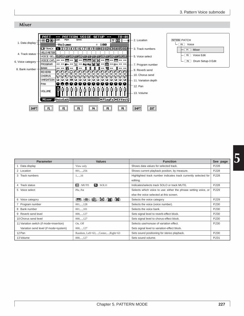
227Chapter 5. PATTERN MODE
5
3. Pattern Voice submode
Mixer
Shows data values for selected track.
Shows current playback position, by measure.
Highlighted track number indicates track currently selected for
editing.
Indicates/selects track SOLO or track MUTE.
Selects which voice to use: either the phrase setting voice, or
else the voice selected at this screen.
Selects the voice category
Selects the voice (voice number).
Selects the voice bank.
Sets signal level to reverb-effect block.
Sets signal level to chorus-effect block.
Selects use/nonuse of variation effect.
Sets signal level to variation-effect block.
Sets sound positioning for stereo playback.
Sets sound volume.
View only
001,...,256
1,...,16
: MUTE : SOLO
Phr, Pat
[ ], [ ], [ ], [ ], [ ], [ ]
001,...,128
001,...,101
000,...,127
000,...,127
On, Off
000,...,127
Random, Left=63,...,Center,...,Right=63
000,...,127
1 Data display
2 Location
3 Track numbers
4 Track status
5 Voice select
6 Voice category
7 Program number
8 Bank number
9 Reverb send level
10 Chorus send level
11 Variation switch (if mode=insertion)
Variation send level (if mode=system)
12 Pan
13 Volume
Parameter Values Function See pageP.228
P.228
P.228
P.228
P.229
P.229
P.230
P.230
P.230
P.230
P.230
P.230
P.231
1. Data display
SHIFT F1 F2 F3 F4 F5 F6 SHIFT EXIT
13. Volume
12. Pan
11. Variation depth
10. Chorus send
9. Reverb send8. Bank number
7. Program number6. Voice category
5. Voice select4. Track status
3. Track numbers
2. Location
1ÊMixer
2ÊVoice Edit
3ÊDrum Setup-3 Edit
pPATCH
2ÊVoice
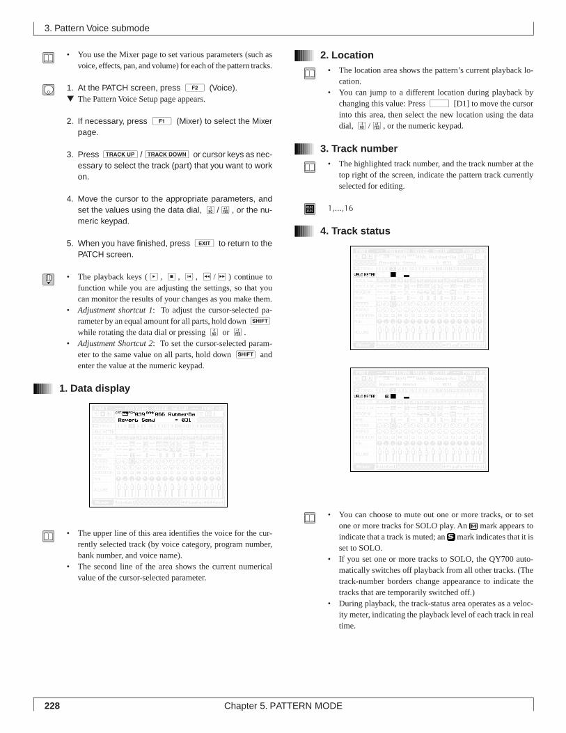
228 Chapter 5. PATTERN MODE
• You use the Mixer page to set various parameters (such asvoice, effects, pan, and volume) for each of the pattern tracks.
1. At the PATCH screen, press 2 (Voice).▼ The Pattern Voice Setup page appears.
2. If necessary, press 1 (Mixer) to select the Mixerpage.
3. Press u/d or cursor keys as nec-essary to select the track (part) that you want to workon.
4. Move the cursor to the appropriate parameters, andset the values using the data dial, n/y, or the nu-meric keypad.
5. When you have finished, press e to return to thePATCH screen.
• The playback keys (p, s, t, r/f) continue tofunction while you are adjusting the settings, so that youcan monitor the results of your changes as you make them.
• Adjustment shortcut 1: To adjust the cursor-selected pa-rameter by an equal amount for all parts, hold down s
while rotating the data dial or pressing n or y.• Adjustment Shortcut 2: To set the cursor-selected param-
eter to the same value on all parts, hold down s andenter the value at the numeric keypad.
1. Data display
• The upper line of this area identifies the voice for the cur-rently selected track (by voice category, program number,bank number, and voice name).
• The second line of the area shows the current numericalvalue of the cursor-selected parameter.
2. Location• The location area shows the pattern’s current playback lo-
cation.• You can jump to a different location during playback by
changing this value: Press d [D1] to move the cursorinto this area, then select the new location using the datadial, n/y, or the numeric keypad.
3. Track number• The highlighted track number, and the track number at the
top right of the screen, indicate the pattern track currentlyselected for editing.
01011101 1,...,16
4. Track status
• You can choose to mute out one or more tracks, or to setone or more tracks for SOLO play. An mark appears toindicate that a track is muted; an mark indicates that it isset to SOLO.
• If you set one or more tracks to SOLO, the QY700 auto-matically switches off playback from all other tracks. (Thetrack-number borders change appearance to indicate thetracks that are temporarily switched off.)
• During playback, the track-status area operates as a veloc-ity meter, indicating the playback level of each track in realtime.
3. Pattern Voice submode
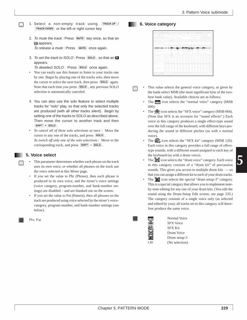
229Chapter 5. PATTERN MODE
5
1. Select a non-empty track using u/d or the left or right cursor key.
2. To mute the track : Press m key once, so that an appears.
To release a mute : Press m once again.
3. To set the track to SOLO : Press s, so that an appears.To deselect SOLO : Press s once again.
• You can easily use this feature to listen to your tracks oneby one. Begin by playing one of the tracks solo, then movethe cursor to select the next track, then press s again.Note that each time you press s, any previous SOLOselection is automatically canceled.
4. You can also use the solo feature to select multipletracks for “solo” play, so that only the selected tracksare produced (with all other tracks silent). Begin bysetting one of the tracks to SOLO as described above.Then move the cursor to another track and thens+s.
• To cancel all of these solo selections at once : Move thecursor to any one of the tracks, and press s.To switch off only one of the solo selections : Move to thecorresponding track, and press s+s.
5. Voice select• This parameter determines whether each phrase on the track
uses its own voice, or whether all phrases on the track usethe voice selected at this Mixer page.
• If you set the value to Phr (Phrase), then each phrase isproduced in its own voice, and the mixer’s voice settings(voice category, program-number, and bank-number set-tings) are disabled – and are blanked out on the screen.
• If you set the value to Pat (Pattern), then all phrases on thetrack are produced using voice selected by the mixer’s voice-category, program-number, and bank-number settings (seebelow).
01011101 Phr, Pat
6. Voice category
• This value selects the general voice category, as given bythe bank-select MSB (the most significant byte of the two-byte bank value). Available choices are as follows.
• The icon selects the “normal voice” category (MSB000).
• The icon selects the “SFX voice” category (MSB 064).(Note that SFX is an acronym for “sound effects”.) Eachvoice in this category produces a single effect-type soundover the full range of the keyboard, with different keys pro-ducing the sound in different pitches (as with a normalvoice).
• The icon selects the “SFX kit” category (MSB 126).Each voice in this category provides a full range of effect-type sounds, with a different sound assigned to each key ofthe keyboard (as with a drum voice).
• The icon selects the “drum voice” category. Each voicein this category consists of a “drum kit” of percussionsounds. This gives you access to multiple drum kits — sothat you can assign a different kit to each of your drum tracks.
• The icon selects the special “drum setup-3” category.This is a special category that allows you to implement note-by-note editing for any one of your drum kits. (You edit thesound using the Drum-Setup Edit screen; see page 235.)The category consists of a single voice only (as selectedand edited by you); all tracks set to this category will there-fore produce the same voice.
01011101 Normal Voice
SFX VoiceSFX KitDrum VoiceDrum setup-3
Off (No selection)
3. Pattern Voice submode
230 Chapter 5. PATTERN MODE
7. Program number• This number selects the voice within the category. (Note
that the voice selection is determined by all three values:category, program number, and bank number.)
• To change this value, you must move the cursor to the PRO-GRAM line. Notice that the PROGRAM line displays theselections in icon form; you must look up at the data dis-play line (at the top of the screen) to view the actual pro-gram number and voice name.
• Available selections vary according to the voice category.• During playback, the program setting changes in accord-
ance with program change messages recorded on the track.
01011101 001,...,128
• For general information about voice selection, refer to Chap-ter 1. (→ p.43)
• For a full listing of voice names and numbers, refer to theQY700 Reference Listings.
8. Bank Number• This is the third and last parameter used in selecting the
voice. This parameter gives the bank LSB for the voice (theleast significant byte of the bank-select argument).
• Remember that the voice selection is determined by the com-bination of the three values: the category (bank MSB), theprogram number, and the bank number (bank LSB).
• The bank number is meaningful only with voices in thenormal category ( ). For all other categories, the numberis fixed at 0.
01011101 000,...,101 (but many values unavailable)
• For general information about bank selection, refer to Chap-ter 1. (→ p.44)
• For a full bank listing, refer to the QY700 Reference List-ings.
9. Reverb send level• This value sets the level of the signal sent to the reverb block.• Use this value in conjunction with the PATTERN EFFECTS
“reverb return” setting. (→ p.241, 242)
01011101 000,...,127
10. Chorus send level• This value sets the level of the signal sent to the chorus
block.• Use this value in conjunction with the PATTERN EFFECTS
“chorus return” setting (→ p.241, 242).
01011101 000,...,127
11. Variation switch/variation send level• The type of setting you can make here depends on whether
the variation mode is set to “insertion” or “system.”• If the mode is “insertion,” then this setting is an ON/OFF
switch. The switch determines which one (if any) of theparts receives the variation effect. Note that you can set theswitch ON for one part (track) only. (When you set the valueto ON, any other ON setting automatically changes to OFF.
• If the mode is “system,” then this setting sets the signal levelto the variation. In this case, you can set the level separatelyfor each track (part).
• Use this value in conjunction with the PATTERN EFFECTS“variation return” setting. (→ p.241, 243)
01011101 Variation switch (if variation mode = “insertion”)
Off, OnVariation send level (if variation mode = “system”)
000,...,127
12. Pan• This value sets the sound positioning for stereo playback.• The pan value changes during replay in accordance with
the track’s MIDI pan data.• If the track is set for a drum voice, the pan setting that you
make here is applied as an offset to the pan value set inter-nally for each of the voice’s instrument sounds.
• Left=63 sets the position all the way to the left; Right=63sets it all the way to the right.
• If you set the pan to Random, the position changes at ran-dom each time a new note is sounded.
01011101 Random [0], Left=63 [1],...,Center [64],...,Right=63 [127]
3. Pattern Voice submode
231Chapter 5. PATTERN MODE
5
13. Volume• This parameter sets the volume for the part.• During replay, the volume changes in accordance with the
track’s MIDI volume data.
01011101 000,...,127
3. Pattern Voice submode
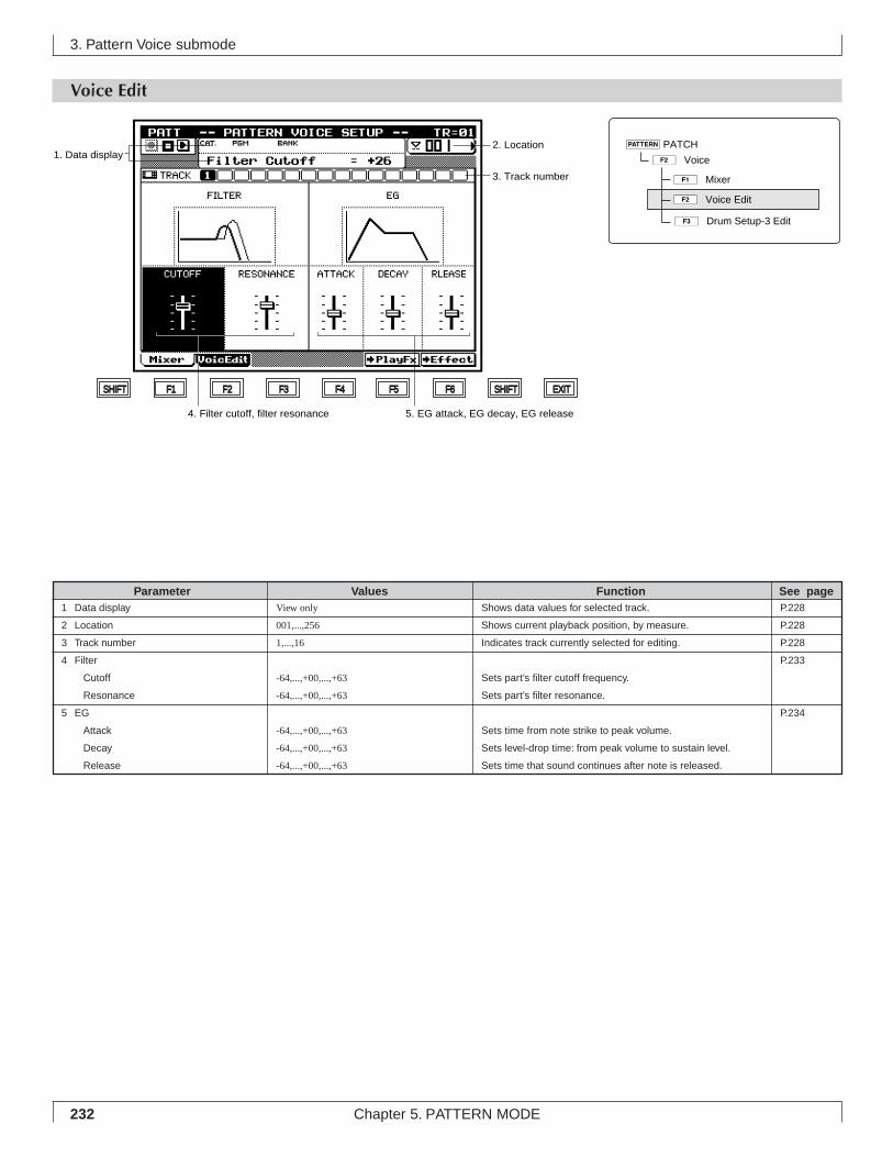
232 Chapter 5. PATTERN MODE
3. Pattern Voice submode
Shows data values for selected track.
Shows current playback position, by measure.
Indicates track currently selected for editing.
Sets part’s filter cutoff frequency.
Sets part’s filter resonance.
Sets time from note strike to peak volume.
Sets level-drop time: from peak volume to sustain level.
Sets time that sound continues after note is released.
View only
001,...,256
1,...,16
-64,...,+00,...,+63
-64,...,+00,...,+63
-64,...,+00,...,+63
-64,...,+00,...,+63
-64,...,+00,...,+63
1 Data display
2 Location
3 Track number
4 Filter
Cutoff
Resonance
5 EG
Attack
Decay
Release
Parameter Values Function See pageP.228
P.228
P.228
P.233
P.234
Voice Edit
1. Data display
3. Track number
SHIFT F1 F2 F3 F4 F5 F6 SHIFT EXIT
2. Location
4. Filter cutoff, filter resonance 5. EG attack, EG decay, EG release
1ÊMixer
2ÊVoice Edit
3ÊDrum Setup-3 Edit
pPATCH
2ÊVoice
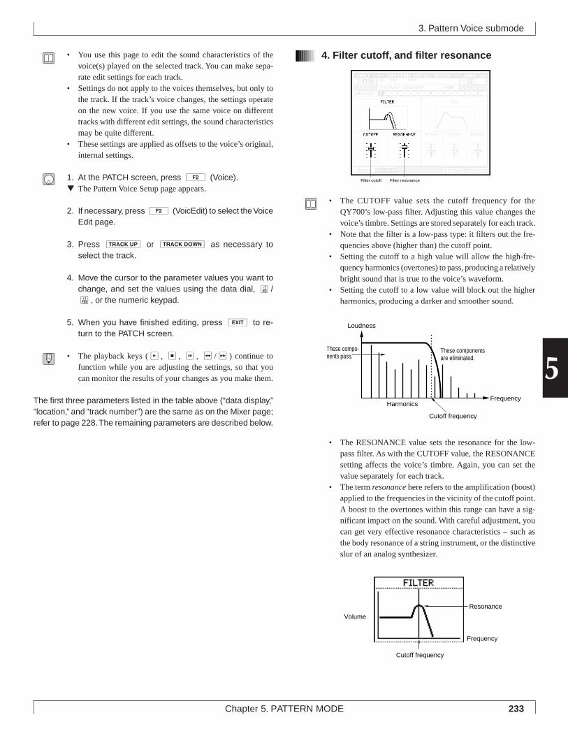
233Chapter 5. PATTERN MODE
5
• You use this page to edit the sound characteristics of thevoice(s) played on the selected track. You can make sepa-rate edit settings for each track.
• Settings do not apply to the voices themselves, but only tothe track. If the track’s voice changes, the settings operateon the new voice. If you use the same voice on differenttracks with different edit settings, the sound characteristicsmay be quite different.
• These settings are applied as offsets to the voice’s original,internal settings.
1. At the PATCH screen, press 2 (Voice).▼ The Pattern Voice Setup page appears.
2. If necessary, press 2 (VoicEdit) to select the VoiceEdit page.
3. Press u or d as necessary toselect the track.
4. Move the cursor to the parameter values you want tochange, and set the values using the data dial, n/y, or the numeric keypad.
5. When you have finished editing, press e to re-turn to the PATCH screen.
• The playback keys (p, s, t, r/f) continue tofunction while you are adjusting the settings, so that youcan monitor the results of your changes as you make them.
The first three parameters listed in the table above (“data display,”“location,” and “track number”) are the same as on the Mixer page;refer to page 228. The remaining parameters are described below.
4. Filter cutoff, and filter resonance
• The CUTOFF value sets the cutoff frequency for theQY700’s low-pass filter. Adjusting this value changes thevoice’s timbre. Settings are stored separately for each track.
• Note that the filter is a low-pass type: it filters out the fre-quencies above (higher than) the cutoff point.
• Setting the cutoff to a high value will allow the high-fre-quency harmonics (overtones) to pass, producing a relativelybright sound that is true to the voice’s waveform.
• Setting the cutoff to a low value will block out the higherharmonics, producing a darker and smoother sound.
• The RESONANCE value sets the resonance for the low-pass filter. As with the CUTOFF value, the RESONANCEsetting affects the voice’s timbre. Again, you can set thevalue separately for each track.
• The term resonance here refers to the amplification (boost)applied to the frequencies in the vicinity of the cutoff point.A boost to the overtones within this range can have a sig-nificant impact on the sound. With careful adjustment, youcan get very effective resonance characteristics – such asthe body resonance of a string instrument, or the distinctiveslur of an analog synthesizer.
3. Pattern Voice submode
Filter cutoff Filter resonance
Frequency
Loudness
Cutoff frequency
Harmonics
These compo-nents pass.
These components are eliminated.
Cutoff frequency
Resonance
Frequency
Volume
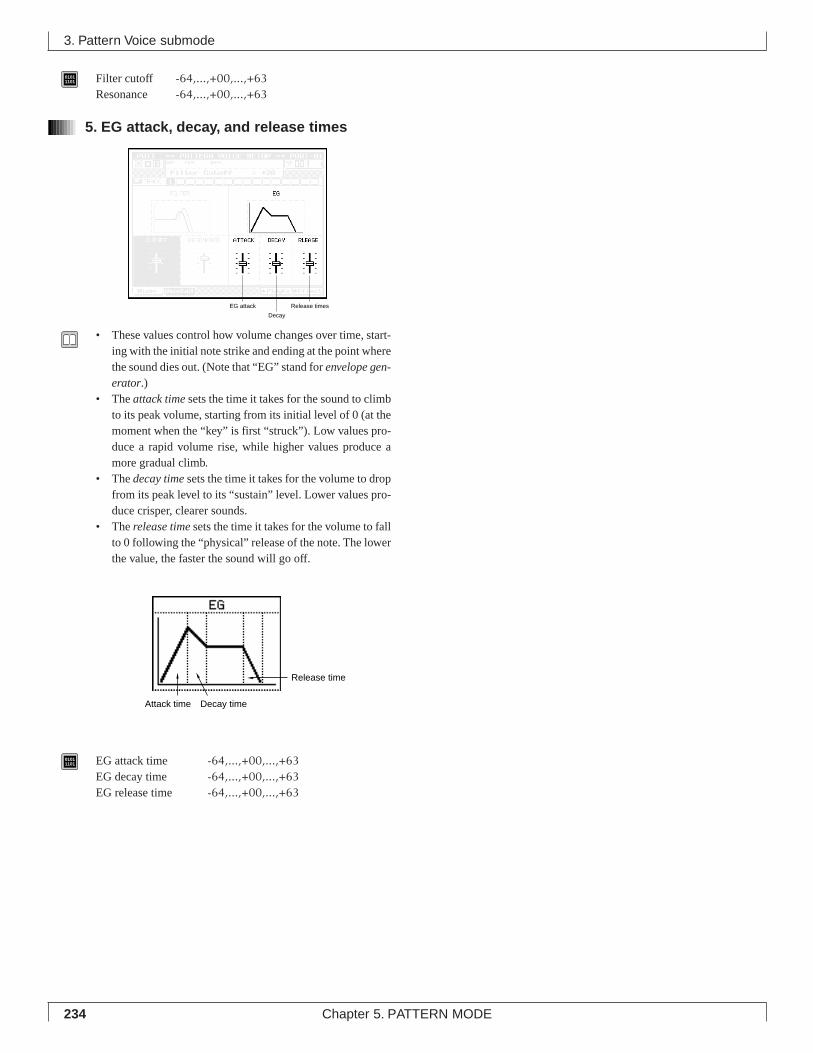
234 Chapter 5. PATTERN MODE
01011101 Filter cutoff -64,...,+00,...,+63
Resonance -64,...,+00,...,+63
5. EG attack, decay, and release times
• These values control how volume changes over time, start-ing with the initial note strike and ending at the point wherethe sound dies out. (Note that “EG” stand for envelope gen-erator.)
• The attack time sets the time it takes for the sound to climbto its peak volume, starting from its initial level of 0 (at themoment when the “key” is first “struck”). Low values pro-duce a rapid volume rise, while higher values produce amore gradual climb.
• The decay time sets the time it takes for the volume to dropfrom its peak level to its “sustain” level. Lower values pro-duce crisper, clearer sounds.
• The release time sets the time it takes for the volume to fallto 0 following the “physical” release of the note. The lowerthe value, the faster the sound will go off.
01011101 EG attack time -64,...,+00,...,+63
EG decay time -64,...,+00,...,+63EG release time -64,...,+00,...,+63
3. Pattern Voice submode
EG attack
Decay
Release times
Attack time Decay time
Release time
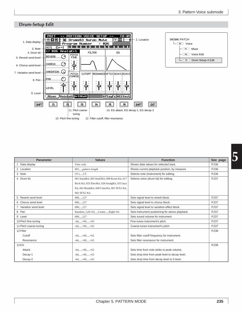
235Chapter 5. PATTERN MODE
5
3. Pattern Voice submode
Drum-Setup Edit
Shows data values for selected track.
Shows current playback position, by measure.
Selects note (instrument) for editing.
Selects voice (drum kit) for editing.
Sets signal level to reverb block.
Sets signal level to chorus block.
Sets signal level to variation-effect block.
Sets instrument positioning for stereo playback.
Sets sound volume for instrument.
Fine-tunes instrument’s pitch.
Coarse-tunes instrument’s pitch.
Sets filter cutoff frequency for instrument.
Sets filter resonance for instrument.
Sets time from note strike to peak volume.
Sets drop time from peak level to decay level.
Sets drop time from decay level to 0 level.
View only
001,...,pattern length
C#-1,...,C5
001 StandKit, 002 Stnd2Kit, 009 Room Kit, 017
Rock Kit, 025 ElectKit, 026 AnalgKit, 033 Jazz
Kit, 041 BrushKit, 049 ClascKit, 001 SFX1 Kit,
002 SFX2 Kit
000,...,127
000,...,127
000,...,127
Random, Left=63,...,Center,...,Right=63
000,...,127
-64,...,+00,...,+63
-64,...,+00,...,+63
-64,...,+00,...,+63
-64,...,+00,...,+63
-64,...,+00,...,+63
-64,...,+00,...,+63
-64,...,+00,...,+63
Parameter Values Function See pageP.236
P.236
P.236
P.237
P.237
P.237
P.237
P.237
P.237
P.237
P.237
P.238
P.238
1 Data display
2 Location
3 Note
4 Drum kit
5 Reverb send level
6 Chorus send level
7 Variation send level
8 Pan
9 Level
10 Pitch fine-tuning
11 Pitch coarse-tuning
12 Filter
Cutoff
Resonance
13 EG
Attack
Decay-1
Decay-2
13. EG attack, EG decay-1, EG decay-2
12. Filter cutoff, filter resonance
SHIFT F1 F2 F3 F4 F5 F6 SHIFT EXIT
11. Pitch coarse-tuning
10. Pitch fine-tuning
9. Level
8. Pan
7. Variation send level
6. Chorus send level
5. Reverb send level
1. Data display
3. Note
4. Drum kit
2. Location
1ÊMixer
2ÊVoice Edit
3ÊDrum Setup-3 Edit
pPATCH
2ÊVoice
236 Chapter 5. PATTERN MODE
• This Drum-Setup Edit feature lets you select one drum voicefor note-by-note (instrument by instrument) editing. You canedit the sound characteristic of each instrument by adjust-ing its filter values, EG values, pitch, and so on.
• This Drum Setup Edit page is available only for tracks whosevoice category has been set to “drum setup-3.” (On the Voiceand Mixer pages, the 3 (DrS3Edit) switch appears onlywhile the cursor is at a track that is set to this category.)
• The “drum setup-3” category consists of one voice only –the voice you create at this Drum Setup Edit page. If two ormore tracks are set to this category, all of these tracks willplay the same voice. If you change the edit values at theDrum Setup Edit page, the changes will apply to all of thesetracks.
• A drum voice (or “drum kit”) consists of a collection ofdifferent “instruments,” with each instrument assigned to adifferent key on the keyboard, starting at key C
#-1 and ex-
tending to C5. (This is in contrast with a “normal voice,”where a single instrument applies across the entire key-board.) For a listing of the various drum voices and theirinstrument arrangements, refer to the QY700 Reference List-ings.
• When you work at the Drum Setup Edit page, you work ona single drum-voice only. If you change the drum-voice se-lection while you are editing, all of the edit settings returnto their defaults. Be sure that you have selected the correctdrum kit before you begin your editing.
• Note that the filter and EG settings made at this page areapplied as offsets to the voice’s internal filter/EG settings.The other settings that you make at this page (PITCH, CHO-RUS, and so on) are used as replacements for the voice’soriginal settings.
1. At the PATCH screen, press 2 (Voice). Then press1 (Mixer) to display the Mixer page.
2. Move the cursor to a track whose voice category is setto “drum setup-3.” (If necessary, move the cursor tothe VOICE CAT. line and set the category to this value.)
▼ The 3 (DrS3Edit) switch appears (on the bottom lineof the screen).
3. Press 3 (DrS3Edit) to move to the Drum SetupEdit page.
4. Move the cursor to the drum-kit setting and select thedrum voice you want to use.
5. Now edit each of the instruments in the kit by repeat-ing the following steps.a) Press the appropriate key on the microkeyboard to se-
lect the instrument (note) that you want to edit.b) Move the cursor to each of the parameter values that
you want to change.c) Enter your change using the data dial, n/y, or the
numeric keypad.
6. When you have finished, press e to return to thePATCH screen, or press one of the function buttons tomove to a different screen.
• The playback keys (p, s, t, r/f) continue tofunction while you are adjusting the settings, so that youcan monitor the results of your changes as you make them.
1. Data display
• The top line of the data-display area shows the name of theinstrument currently selected for editing. This value changeseach time you press a different key on the microkeyboard.
• The lower line shows the program number of the selecteddrum voice.
2. Location• This location area shows the pattern’s current playback lo-
cation (measure).• You can jump to a different location during playback by
changing this value: Press d [D1] to move the cursorinto this area, then select the new location using the datadial, n/y, or the numeric keypad.
01011101 001,...,pattern length
3. Note• This area shows the currently selected note. (You select the
note by pressing the appropriate key on the microkeyboard.)Each note corresponds to a different instrument in the kit.
• The note/instrument correspondence is different for eachdrum voice. For complete listings of the instrument arrange-ments within each voice, refer to the QY700 Reference List-ings.
01011101 C#-1,...,C5
3. Pattern Voice submode
237Chapter 5. PATTERN MODE
5
4. Drum kit• This area selects the drum voice (drum kit) to be edited.
Each voice consists of a kit of instruments, with each in-strument assigned to a different note on the keyboard.
• As explained above, you can apply editing to one drum kitonly. If you change the kit setting (either purposely or byaccident), all editing parameters on this page immediatelyreturn to their defaults. Be sure to select the correct kit be-fore making your editing changes; do not change the kitunless you wish to restart the entire editing process.
01011101 001 StandKit, 002 Stnd2Kit, 009 Room Kit,
017 Rock Kit, 025 ElectKit, 026 AnalgKit,033 Jazz Kit, 041 BrushKit, 049 ClascKit,001 SFX1 Kit, 002 SFX2 Kit
5. Reverb send level• This value sets the signal level to the reverb block. Raising
this value increases the amount of reverb applied to the in-strument.
• Keep in mind that total reverb application depends also onthe mixer’s reverb send level (→ p.230) and the PATTERNEFFECTS reverb return level. (→ p.241, 242)
01011101 000,...,127
6. Chorus send level• This value sets the signal level to the chorus block. Raising
this value increases the amount of chorus effect applied tothe instrument.
• Note that total chorus-effect application depends also onthe mixer’s chorus send level (→ p.230) and the PATTERNEFFECTS chorus return level. (→ p.241, 242)
01011101 000,...,127
7.Variation send level• This value sets the signal level to the variation-effect block.
The numerical setting is effective only if the variation mode(→ p.242) is set to “system” (see below). Provided that themode is “system”, you can use this feature to set a differentvariation-effect level for each instrument in the kit.
• Note that the actual effect application depends also on theEFFECT mode’s variation-return setting.
• If the variation mode is “system,” then the level to the vari-ation-effect block varies according to the numerical valueyou set here. If the mode is “insertion,” however, then asetting of 000 switches the variation-effect off, while anyother value (from 001 to 127) switches the effect on. (Seepage 242 for information about the variation-mode setting.)
01011101 000,...,127
8. Pan• This value sets the instrument position for stereo playback.
(The position is determined relative to the left and rightspeakers.)
• You can get the most natural effect by setting instrumentpositions to match the arrangement of a true drum set.
01011101 Random, Left=63,...,Center,...,Right=63
(where Random causes the instrument’s position to change atrandom each time it is played.)
9. Level• This value sets the instrument’s volume.
01011101 000,...,127
10. Pitch fine-tuning• This setting fine-tunes the instrument’s pitch, in 1-cent in-
crements (where 1 cent corresponds to 1/100 semitone).
01011101 -64,...,+00,...,+63
11. Pitch coarse-tuning• This setting coarse-tunes the instrument’s pitch, in semi-
tone increments.• A value of 00 retains the instrument’s original pitch (the
pitch recorded when the instrument was sampled).• You can use this adjustment to set up melodic toms or other
kinds of pitched drum play. Note that changes to the pitchmay cause changes in the instrument’s sound characteris-tics.
• After setting the coarse pitch, you can apply fine tuning byadjusting the “pitch fine-tuning” value described above.
01011101 -64,...,+00,...,+63
3. Pattern Voice submode
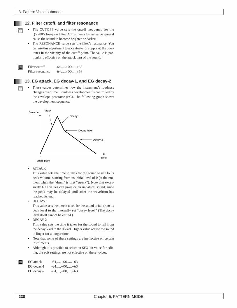
238 Chapter 5. PATTERN MODE
12. Filter cutoff, and filter resonance• The CUTOFF value sets the cutoff frequency for the
QY700’s low-pass filter. Adjustments to this value generalcause the sound to become brighter or darker.
• The RESONANCE value sets the filter’s resonance. Youcan use this adjustment to accentuate (or suppress) the over-tones in the vicinity of the cutoff point. The value is par-ticularly effective on the attack part of the sound.
01011101 Filter cutoff -64,...,+00,...,+63
Filter resonance -64,...,+00,...,+63
13. EG attack, EG decay-1, and EG decay-2• These values determines how the instrument’s loudness
changes over time. Loudness development is controlled bythe envelope generator (EG). The following graph showsthe development sequence.
• ATTACKThis value sets the time it takes for the sound to rise to itspeak volume, starting from its initial level of 0 (at the mo-ment when the “drum” is first “struck”). Note that exces-sively high values can produce an unnatural sound, sincethe peak may be delayed until after the waveform hasreached its end.
• DECAY-1This value sets the time it takes for the sound to fall from itspeak level to the internally set “decay level.” (The decaylevel itself cannot be edited.)
• DECAY-2This value sets the time it takes for the sound to fall fromthe decay level to the 0 level. Higher values cause the soundto linger for a longer time.
• Note that some of these settings are ineffective on certaininstruments.
• Although it is possible to select an SFX-kit voice for edit-ing, the edit settings are not effective on these voices.
01011101 EG attack -64,...,+00,...,+63
EG decay-1 -64,...,+00,...,+63EG decay-2 -64,...,+00,...,+63
3. Pattern Voice submode
Attack
Decay-1
Decay level
Decay-2
Strike pointTime
Volume
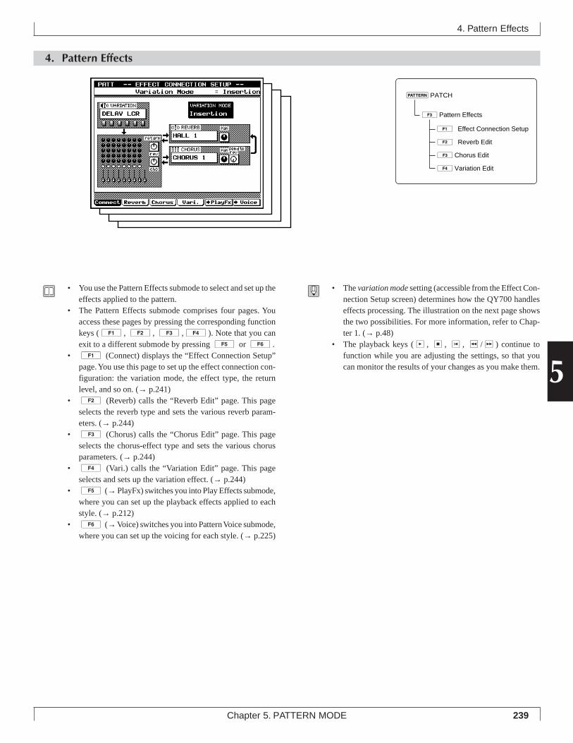
239Chapter 5. PATTERN MODE
5
4. Pattern Effects
4. Pattern Effects
• You use the Pattern Effects submode to select and set up theeffects applied to the pattern.
• The Pattern Effects submode comprises four pages. Youaccess these pages by pressing the corresponding functionkeys (1, 2, 3,4). Note that you canexit to a different submode by pressing 5 or 6.
• 1 (Connect) displays the “Effect Connection Setup”page. You use this page to set up the effect connection con-figuration: the variation mode, the effect type, the returnlevel, and so on. (→ p.241)
• 2 (Reverb) calls the “Reverb Edit” page. This pageselects the reverb type and sets the various reverb param-eters. (→ p.244)
• 3 (Chorus) calls the “Chorus Edit” page. This pageselects the chorus-effect type and sets the various chorusparameters. (→ p.244)
• 4 (Vari.) calls the “Variation Edit” page. This pageselects and sets up the variation effect. (→ p.244)
• 5 (→ PlayFx) switches you into Play Effects submode,where you can set up the playback effects applied to eachstyle. (→ p.212)
• 6 (→ Voice) switches you into Pattern Voice submode,where you can set up the voicing for each style. (→ p.225)
• The variation mode setting (accessible from the Effect Con-nection Setup screen) determines how the QY700 handleseffects processing. The illustration on the next page showsthe two possibilities. For more information, refer to Chap-ter 1. (→ p.48)
• The playback keys (p, s, t, r/f) continue tofunction while you are adjusting the settings, so that youcan monitor the results of your changes as you make them.
3Pattern Effects
1ÊEffect Connection Setup
2ÊReverb Edit
3Chorus Edit
4Variation Edit
pPATCH
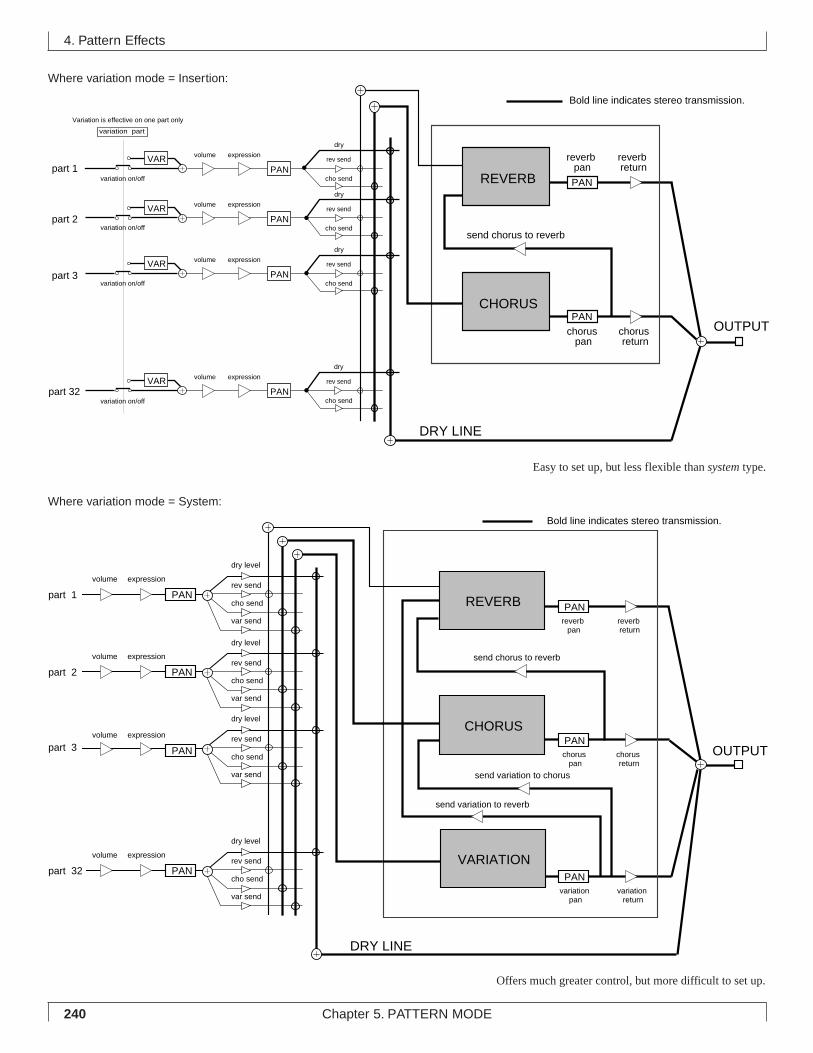
240 Chapter 5. PATTERN MODE
4. Pattern Effects
Where variation mode = Insertion:
Offers much greater control, but more difficult to set up.
rev send
cho send
dry
reverb return
chorus return
send chorus to reverb
DRY LINE
PAN
reverb pan
chorus pan
OUTPUT
Bold line indicates stereo transmission.
rev send
cho send
dry
rev send
cho send
dry
rev send
cho send
dry
variation part
part 3
part 32
Variation is effective on one part only
part 1
part 2
VAR
VAR
VAR
VAR
variation on/off
variation on/off
variation on/off
variation on/offPAN
volume expression
PAN
volume expression
PAN
volume expression
PAN
volume expression
REVERB
CHORUSPAN
Easy to set up, but less flexible than system type.
Where variation mode = System:
part 1
VARIATION
REVERB
send chorus to reverb
send variation to chorus
send variation to reverb
DRY LINE
PANreverb return
reverb pan
OUTPUT
Bold line indicates stereo transmission.
CHORUS
part 2
part 3
part 32
chorus return
chorus pan
variation return
variation pan
var send
var send
var send
rev send
rev send
rev send
cho send
cho send
cho send
dry level
dry level
dry level
dry level
var send
rev send
cho send
PAN
PAN
PAN
volume expression
PAN
volume expression
PAN
volume expression
PAN
volume expression
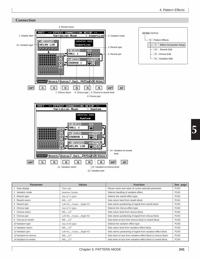
241Chapter 5. PATTERN MODE
5
Connection
4. Pattern Effects
Shows name and value of cursor-selected parameter.
Selects handling of variation effect.
Selects the reverb-effect type.
Sets return level from reverb block.
Sets stereo positioning of signal from reverb block.
Selects the chorus-effect type.
Sets return level from chorus block.
Sets stereo positioning of signal from chorus block.
Sets level on bus from chorus block to reverb block.
Selects the variation effect type.
Sets return level from variation-effect block.
Sets stereo positioning of signal from variation-effect block.
Sets level on bus from variation-effect block to chorus block.
Sets level on bus from variation-effect block to reverb block.
View only
Insertion, System
Any of 11 types.
000,...,127
Left=63,...,Center,...,Right=63
Any of 11 types.
000,...,127
Left=63,...,Center,...,Right=63
000,...,127
Any of 43 types.
000,...,127
Left=63,...,Center,...,Right=63
000,...,127
000,...,127
Parameter Values Function See pageP.242
P.242
P.242
P.242
P.242
P.242
P.242
P.242
P.243
P.243
P.243
P.243
P.243
P.243
1 Data display
2 Variation mode
3 Reverb type
4 Reverb return
5 Reverb pan
6 Chorus type
7 Chorus return
8 Chorus pan
9 Chorus-to-reverb
10 Variation type
11 Variation return
12 Variation pan
13 Variation-to-chorus
14 Variation-to-reverb
3Pattern Effects
1ÊEffect Connection Setup
2ÊReverb Edit
3Chorus Edit
4Variation Edit
pPATCH
11. Variation return
14. Variation-to-reverb level
13. Variation-to-chorus level
12. Variation pan
SHIFT F1 F2 F3 F4 F5 F6 SHIFT EXIT
SHIFT F1 F2 F3 F4 F5 F6 SHIFT EXIT
9. Chorus-to-reverb level
8. Chorus pan
6. Chorus type7. Chorus return
4. Reverb return
1. Display data
10. Variation type3. Reverb type
5. Reverb pan
2. Variation mode
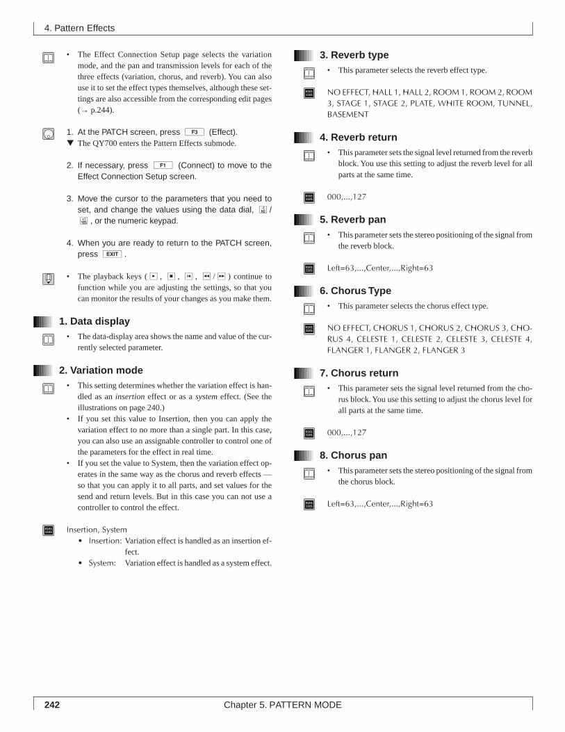
242 Chapter 5. PATTERN MODE
• The Effect Connection Setup page selects the variationmode, and the pan and transmission levels for each of thethree effects (variation, chorus, and reverb). You can alsouse it to set the effect types themselves, although these set-tings are also accessible from the corresponding edit pages(→ p.244).
1. At the PATCH screen, press 3 (Effect).▼ The QY700 enters the Pattern Effects submode.
2. If necessary, press 1 (Connect) to move to theEffect Connection Setup screen.
3. Move the cursor to the parameters that you need toset, and change the values using the data dial, n/y, or the numeric keypad.
4. When you are ready to return to the PATCH screen,press e.
• The playback keys (p, s, t, r/f) continue tofunction while you are adjusting the settings, so that youcan monitor the results of your changes as you make them.
1. Data display• The data-display area shows the name and value of the cur-
rently selected parameter.
2. Variation mode• This setting determines whether the variation effect is han-
dled as an insertion effect or as a system effect. (See theillustrations on page 240.)
• If you set this value to Insertion, then you can apply thevariation effect to no more than a single part. In this case,you can also use an assignable controller to control one ofthe parameters for the effect in real time.
• If you set the value to System, then the variation effect op-erates in the same way as the chorus and reverb effects —so that you can apply it to all parts, and set values for thesend and return levels. But in this case you can not use acontroller to control the effect.
01011101 Insertion, System
• Insertion: Variation effect is handled as an insertion ef-fect.
• System: Variation effect is handled as a system effect.
3. Reverb type• This parameter selects the reverb effect type.
01011101 NO EFFECT, HALL 1, HALL 2, ROOM 1, ROOM 2, ROOM
3, STAGE 1, STAGE 2, PLATE, WHITE ROOM, TUNNEL,BASEMENT
4. Reverb return• This parameter sets the signal level returned from the reverb
block. You use this setting to adjust the reverb level for allparts at the same time.
01011101 000,...,127
5. Reverb pan• This parameter sets the stereo positioning of the signal from
the reverb block.
01011101 Left=63,...,Center,...,Right=63
6. Chorus Type• This parameter selects the chorus effect type.
01011101 NO EFFECT, CHORUS 1, CHORUS 2, CHORUS 3, CHO-
RUS 4, CELESTE 1, CELESTE 2, CELESTE 3, CELESTE 4,FLANGER 1, FLANGER 2, FLANGER 3
7. Chorus return• This parameter sets the signal level returned from the cho-
rus block. You use this setting to adjust the chorus level forall parts at the same time.
01011101 000,...,127
8. Chorus pan• This parameter sets the stereo positioning of the signal from
the chorus block.
01011101 Left=63,...,Center,...,Right=63
4. Pattern Effects
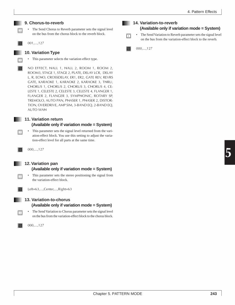
243Chapter 5. PATTERN MODE
5
9. Chorus-to-reverb• The Send Chorus to Reverb parameter sets the signal level
on the bus from the chorus block to the reverb block.
01011101 001,...,127
10. Variation Type• This parameter selects the variation effect type.
01011101 NO EFFECT, HALL 1, HALL 2, ROOM 1, ROOM 2,
ROOM3, STAGE 1, STAGE 2, PLATE, DELAY LCR, DELAYL, R, ECHO, CROSSDELAY, ER1, ER2, GATE REV, REVRSGATE, KARAOKE 1, KARAOKE 2, KARAOKE 3, THRU,CHORUS 1, CHORUS 2, CHORUS 3, CHORUS 4, CE-LESTE 1, CELESTE 2, CELESTE 3, CELESTE 4, FLANGER 1,FLANGER 2, FLANGER 3, SYMPHONIC, ROTARY SP,TREMOLO, AUTO PAN, PHASER 1, PHASER 2, DISTOR-TION, OVERDRIVE, AMP SIM, 3-BAND EQ, 2-BAND EQ,AUTO WAH
11. Variation return(Available only if variation mode = System)
• This parameter sets the signal level returned from the vari-ation-effect block. You use this setting to adjust the varia-tion-effect level for all parts at the same time.
01011101 000,...,127
12. Variation pan(Available only if variation mode = System)
• This parameter sets the stereo positioning the signal fromthe variation-effect block.
01011101 Left=63,...,Center,...,Right=63
13. Variation-to-chorus(Available only if variation mode = System)
• The Send Variation to Chorus parameter sets the signal levelon the bus from the variation-effect block to the chorus block.
01011101 000,...,127
14. Variation-to-reverb(Available only if variation mode = System)
• The Send Variation to Reverb parameter sets the signal levelon the bus from the variation-effect block to the reverb.
01011101 000,...,127
4. Pattern Effects
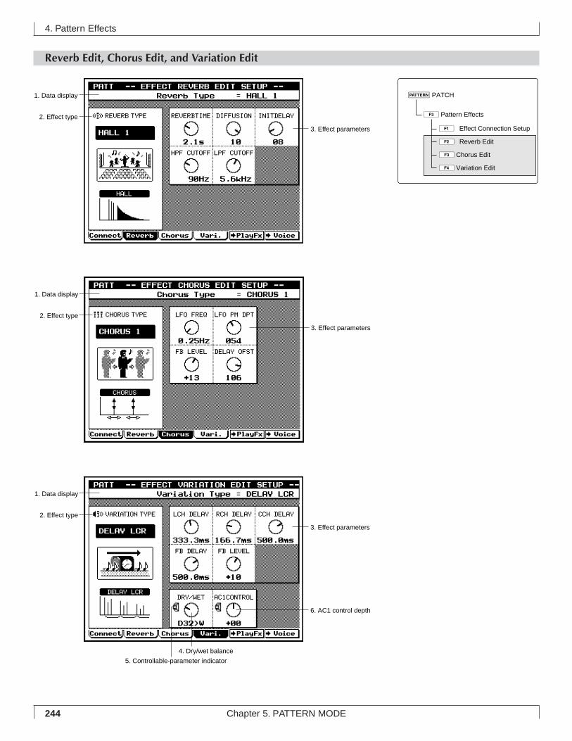
244 Chapter 5. PATTERN MODE
Reverb Edit, Chorus Edit, and Variation Edit
4. Pattern Effects
1. Data display
2. Effect type
3. Effect parameters
1. Data display
2. Effect type
3. Effect parameters
1. Data display
2. Effect type
5. Controllable-parameter indicator
4. Dry/wet balance
6. AC1 control depth
3. Effect parameters
3Pattern Effects
1ÊEffect Connection Setup
2ÊReverb Edit
3Chorus Edit
4Variation Edit
pPATCH
245Chapter 5. PATTERN MODE
5
4. Pattern Effects
Shows name and value of cursor-selected parameter.
Selects the effect type.
Various parameter values for the selected effect.
Sets balance between wet sound (sound passed through varia-
tion effect) and dry (non-effected) sound. Setting appears only if
variation mode is set to Insertion.
Appears beside parameter that can be controlled with AC1 (As-
signable Controller 1).
Sets AC1 control depth for the controllable parameter.
View only
D63>W,...,D=W,...,D<W63
View only
-64,...,+0,...,+63
Parameter Values Function See pageP.245
P.245
P.245
P.245
P.245
P.246
1 Data display
2 Effect type
3 Effect parameters
4 Dry/wet balance
(On Variation Edit page, if mode = Insertion)
5 Controllable parameter
(On Variation Edit page, if mode = Insertion)
6 AC1 control depth
(On Variation Edit page, if mode = Insertion)
• These three pages set the various parameters for the reverbeffect, chorus effect, and variation effect.
1. At the PATCH screen, press 3 (Effect).▼ The QY700 enters the Pattern Effects submode.
2. Press 2 (Reverb), 3 (Chorus), or 4(Vari.) to move to the editing page for the effect thatyou need to edit.
3. Move the cursor to the parameters you need to set,and enter the values using the data dial, n/y, orthe numeric keypad.
4. When you are ready to return to the main PATCHscreen, press e.
• The playback keys (p, s, t, r/f) continue tofunction while you are adjusting the settings, so that youcan monitor the results of your changes as you make them.
1. Data display• The data-display area shows the name and current value of
the parameter selected by the cursor.
2. Effect type• This parameter selects the effect type. Note that you can
also view or change these values at the Effect ConnectionSetup screen. (→ p.241)
• If the variation mode is Insertion and the variation effecttype is NO EFFECT, the QY700 will not produce any soundat all for the part whose variation switch is turned ON.
3. Effect parameters• These values adjust the operation of the selected effect type.
Available parameters vary according to the type.
4. Dry/wet balance(Only on Variation Edit page; only if mode is Insertion)
• This parameter sets the balance between the wet sound (thesound that receives the variation effect) and the dry sound(the sound that does not).
• This parameter appears only if the variation mode is set toInsertion. The dry/wet balance for System-mode operationis fixed at D32>W.
01011101 D63>W,...,D=W,...,D<W63
5. Controllable parameter(Only on Variation Edit page; only if mode is Insertion)
• The mark identifies the parameter that can be controlledin real time with AC1 (Assignable Controller 1).
• This type of control is available only if the variation modeis set to Insertion, and applies only to the part whose varia-tion switch is set on.
246 Chapter 5. PATTERN MODE
6. AC1 control depth(Only on Variation Edit page; only if mode is Insertion)
• This parameter determines how strongly AC1 (AssignableController 1) affects the value of the controllable param-eter.
• If you set the depth to 0, then AC1 has no effect. Highermagnitudes increase the sensitivity of the AC1 control. Thesign of the setting determines the AC1 directionality: a posi-tive sign means that upward displacement of AC1 raises thevalue of the controllable parameter, while a negative signmeans that upward displacement reduces the value.
• Note that an assignable controller is a controller (such as acontrol wheel) whose function can be set by the user. TheQY700 provides two assignable controllers, AC1 and AC2.(You select the function by assigning the appropriate “con-trol number” to the controller. You make these assignmentsby issuing System Exclusive messages.)
• Note that this setting appears only if the variation mode isset to Insertion.
01011101 -64,...,+0,...,+63
4. Pattern Effects
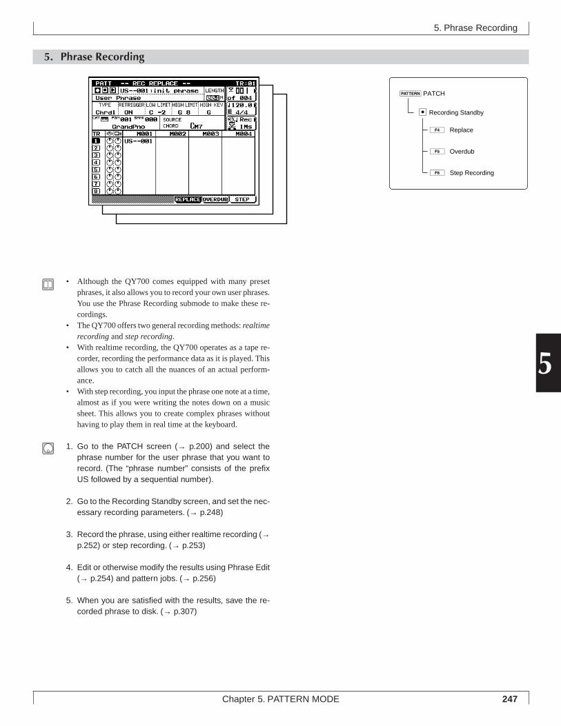
247Chapter 5. PATTERN MODE
5
5. Phrase Recording
5. Phrase Recording
• Although the QY700 comes equipped with many presetphrases, it also allows you to record your own user phrases.You use the Phrase Recording submode to make these re-cordings.
• The QY700 offers two general recording methods: realtimerecording and step recording.
• With realtime recording, the QY700 operates as a tape re-corder, recording the performance data as it is played. Thisallows you to catch all the nuances of an actual perform-ance.
• With step recording, you input the phrase one note at a time,almost as if you were writing the notes down on a musicsheet. This allows you to create complex phrases withouthaving to play them in real time at the keyboard.
1. Go to the PATCH screen (→ p.200) and select thephrase number for the user phrase that you want torecord. (The “phrase number” consists of the prefixUS followed by a sequential number).
2. Go to the Recording Standby screen, and set the nec-essary recording parameters. (→ p.248)
3. Record the phrase, using either realtime recording (→p.252) or step recording. (→ p.253)
4. Edit or otherwise modify the results using Phrase Edit(→ p.254) and pattern jobs. (→ p.256)
5. When you are satisfied with the results, save the re-corded phrase to disk. (→ p.307)
eRecording Standby
4ÊReplace
5ÊOverdub
6ÊStep Recording
pPATCH
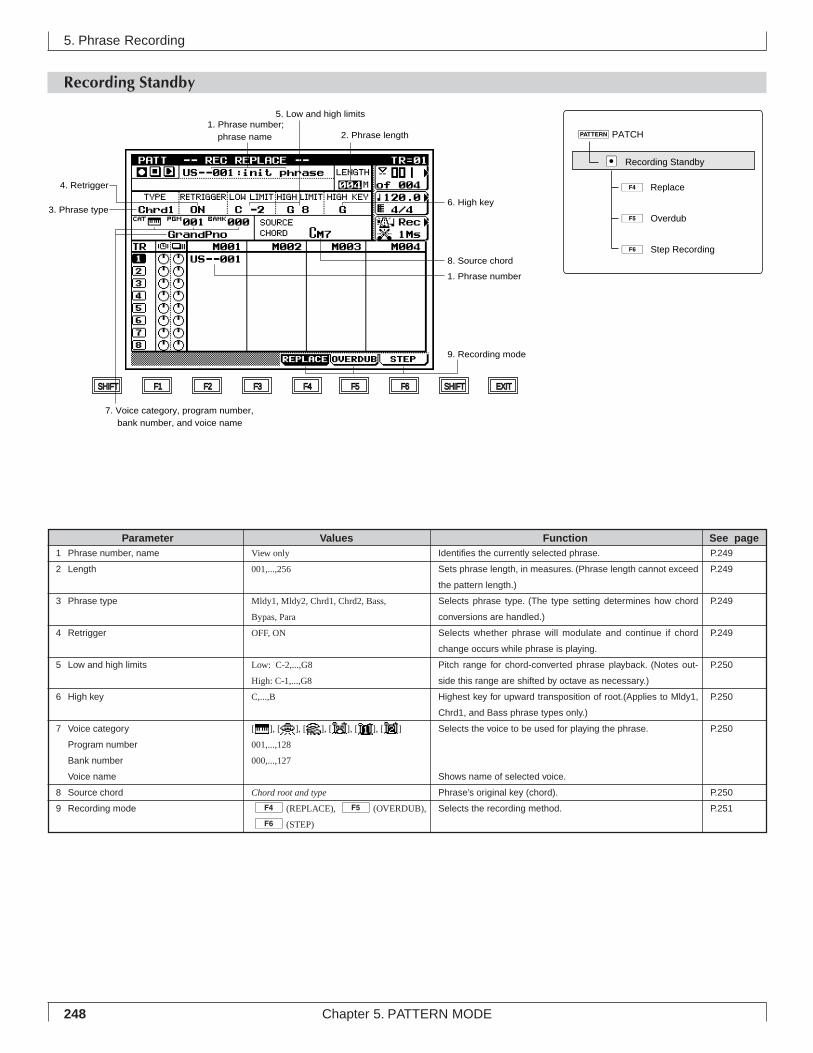
248 Chapter 5. PATTERN MODE
5. Phrase Recording
Recording Standby
Identifies the currently selected phrase.
Sets phrase length, in measures. (Phrase length cannot exceed
the pattern length.)
Selects phrase type. (The type setting determines how chord
conversions are handled.)
Selects whether phrase will modulate and continue if chord
change occurs while phrase is playing.
Pitch range for chord-converted phrase playback. (Notes out-
side this range are shifted by octave as necessary.)
Highest key for upward transposition of root.(Applies to Mldy1,
Chrd1, and Bass phrase types only.)
Selects the voice to be used for playing the phrase.
Shows name of selected voice.
Phrase’s original key (chord).
Selects the recording method.
View only
001,...,256
Mldy1, Mldy2, Chrd1, Chrd2, Bass,
Bypas, Para
OFF, ON
Low: C-2,...,G8
High: C-1,...,G8
C,...,B
[ ], [ ], [ ], [ ], [ ], [ ]
001,...,128
000,...,127
Chord root and type
4(REPLACE), 5(OVERDUB),
6(STEP)
1 Phrase number, name
2 Length
3 Phrase type
4 Retrigger
5 Low and high limits
6 High key
7 Voice category
Program number
Bank number
Voice name
8 Source chord
9 Recording mode
Parameter Values Function See pageP.249
P.249
P.249
P.249
P.250
P.250
P.250
P.250
P.251
7. Voice category, program number, bank number, and voice name
8. Source chord
2. Phrase length
5. Low and high limits
6. High key3. Phrase type
4. Retrigger
1. Phrase number; phrase name
1. Phrase number
9. Recording mode
SHIFT F1 F2 F3 F4 F5 F6 SHIFT EXIT
4ÊReplace
5ÊOverdub
6ÊStep Recording
pPATCH
eÊRecording Standby
249Chapter 5. PATTERN MODE
5
• Before starting actual recording, you must set the relevantrecording parameters at the Recording Standby screen.
1. Go to the PATCH screen (→ p.200) and select thephrase number for the user phrase that you want torecord. (The “phrase number” consists of the prefixUS followed by a sequential number.)
2. Press e to move to the Recording Standby screen.
3. Set the recording parameters (phrase length, retrigger,and so on) and select the recording mode (4 (RE-PLACE), 5 (OVERDUB), or 6 (STEP)).
4. Press p to begin recording.▼ The PLAY indicator comes on (either solid or blinking).
5. When you are finished, press s to stop recordingand return to the PATCH screen.
6. Edit or otherwise manipulate the recording results us-ing Phrase Edit (→ p.254) and pattern jobs (→ p.256).
7. When you are satisfied with the results, store the re-corded phrase to disk. (→ p.307)
• If you press e while in Recording Standby, the QY700returns to the PATCH screen.
1. Phrase number; phrase name• The phrase is identified by its phrase number. You select
the number at the PATCH screen. (→ p.200)• You can use the Phrase Name pattern job to assign the phrase
an arbitrary phrase name. (→ p.279)
2. Length• This parameter sets the length (in measures) for the phrase.• The maximum phrase length is equivalent to the length of
the currently selected pattern (the “of” value appearing inthe upper right box area on the display.)
01011101 001,...,pattern length
(where maximum pattern length = 256)
3. Phrase type• The TYPE value selects the kind of chord conversion used
when modulating (transposing) the phrase. Different typesettings result in different conversion results, as follows.
• The “Melody” types (Mdly1, Mldy2) generate relativelyslight, subtle changes in the playback sound.
• The “Chord” types (Chrd1, Chrd2) generate relatively largechanges in the playback sound.
• For Mldy1 and Chrd1 transpositions, the QY700 first con-verts the original phrase line according to the chord type,and then transposes according to the chord root. For Mldy2and Chrd2 transpositions, the QY700 remains closer to theoriginal sound, so that chord changes are somewhatsmoother.
• The Bass type is designed for bass phrases. For these phrases,the QY700 always produces the root note at the start of anychord change. In addition, transposition is always accord-ing to the target chord’s on-bass or original-bass setting (ifany).
• Use the Bypas (Bypass) setting if you do not want the phraseto be converted at all. In this case, the phrase bypasses theconversion process and plays out in its original sound.
• The Para (parallel) type transposes by root only; the chordtype is ignored. This is useful for phrases that contain im-plicit internal chord changes, since type conversion in thiscase may produce unpredictable or clashing results.
01011101 Mldy1, Mldy2, Chrd1, Chrd2, Bass, Bypas, Para
4. Retrigger• This setting determines how the phrase responds to chord
changes that occur while the phrase is already playing. Ifthe setting is OFF, the phrase switches off when the chordchange occurs. If ON, the QY700 transposes the phrase (inaccordance with the chord-conversion parameters) and con-tinues the playback.
01011101 OFF, ON
5. Phrase Recording
250 Chapter 5. PATTERN MODE
5. Low and high limits• These values select the highest and lowest pitches that can
be used for replay of a transposed phrase. If transpositionproduces a note that is outside the limit, the QY700 shiftsthe note (by octave) to bring it into range.
01011101 Low limit C-2,...,G8
High limit C-1,...,G8
6. High key• This setting determines the highest key that the chord root
can take following transposition. The setting applies onlyto phrases of the following types: Mldy1, Chrd1, and Bass.
• To transpose any of these phrase types, the QY700 normallyshifts the root upwards by the number of semitones separat-ing the source chord’s root and the new chord’s root. Be-cause too large a shift upward can cause the phrase to loseits original character, however, the QY700 will automati-cally shift downward, by one octave, any transposition thatwould move to a root higher than the value set here.
01011101 C,...,B
7. Voice category, program number, banknumber, and voice name
• The first three values (voice category, program number, andbank number) select the voice used to play the phrase. Thescreen also displays the selected voice’s name.
• The voice category selects the general voice class, as givenby the Bank Select MSB (the most significant byte of theBank Select value).
• The program number selects the voice within the category.• The bank number(or Bank Select LSB) can be used to se-
lect one of the alternative voices assigned to the programnumber. This value is effective only with respect to voicesin the “normal” category; the value is fixed at 000 for allother categories.
01011101 Voice category
Normal voice (Bank Select MSB = 000).SFX voice (Bank Select MSB = 064). This type ofSFX voice (sound-effects voice) has the same char-acter over the full range of the keyboard, but differ-ent keys produce the sound in different pitches (aswith a normal voice).SFX kit (Bank Select MSB = 126). This type ofvoice exists as a collection of different sounds, sothat each key produces a different kind of soundeffect.Drum voice (Bank Select MSB = 127). As with theSFX kit, each key produces a different type of drumsound. Note that these sounds cannot be changeddirectly by editing.
Program number001,...,128
Bank number000,...,127
• For more information above voice and bank settings, referto Chapter 1. (→ p.43)
• For a listing of voice names, voice numbers, and bank set-tings, refer to the QY700 Reference Listings.
8. Source chord• This value sets the phrase’s original key (the key and chord
value under which the phrase was originally played). TheQY700 takes this value into account when executing chordconversions on the phrase.
• You can set this value only when recording a new userphrase. Be sure to set the value correctly; an incorrect set-ting may make it impossible for the QY700 to transpose thephrase.
01011101 Chord root
C, C#, D, Eb, E, F, F#, G, Ab, A, Bb, B(Where C# is equivalent to Db, etc.)
Chord typeM, M7, 6, 7, m, m7, m6, mM7, m7(b5), dim, aug, sus4,add9, M7(9), 6(9), 7(9), madd9, m7(9), m7(11), 7(b5),7(#5), 7(b9), 7(#9), 7(13), 7(b13), 7sus4, 7(#11), --- (THRU)
• For information about setting up chords, refer to Chapter 1.(→ p.61)
5. Phrase Recording
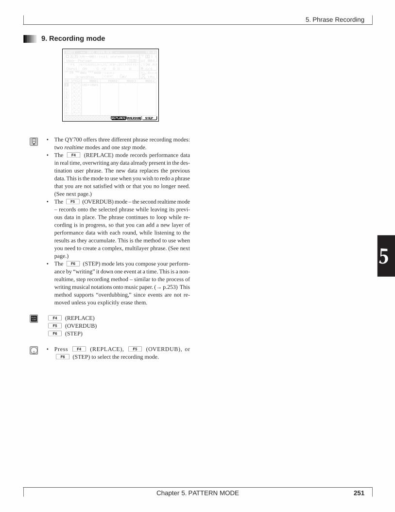
251Chapter 5. PATTERN MODE
5
9. Recording mode
• The QY700 offers three different phrase recording modes:two realtime modes and one step mode.
• The 4 (REPLACE) mode records performance datain real time, overwriting any data already present in the des-tination user phrase. The new data replaces the previousdata. This is the mode to use when you wish to redo a phrasethat you are not satisfied with or that you no longer need.(See next page.)
• The 5 (OVERDUB) mode – the second realtime mode– records onto the selected phrase while leaving its previ-ous data in place. The phrase continues to loop while re-cording is in progress, so that you can add a new layer ofperformance data with each round, while listening to theresults as they accumulate. This is the method to use whenyou need to create a complex, multilayer phrase. (See nextpage.)
• The 6 (STEP) mode lets you compose your perform-ance by “writing” it down one event at a time. This is a non-realtime, step recording method – similar to the process ofwriting musical notations onto music paper. (→ p.253) Thismethod supports “overdubbing,” since events are not re-moved unless you explicitly erase them.
01011101 4 (REPLACE)
5 (OVERDUB)6 (STEP)
• Press 4 (REPLACE), 5 (OVERDUB), or6 (STEP) to select the recording mode.
5. Phrase Recording
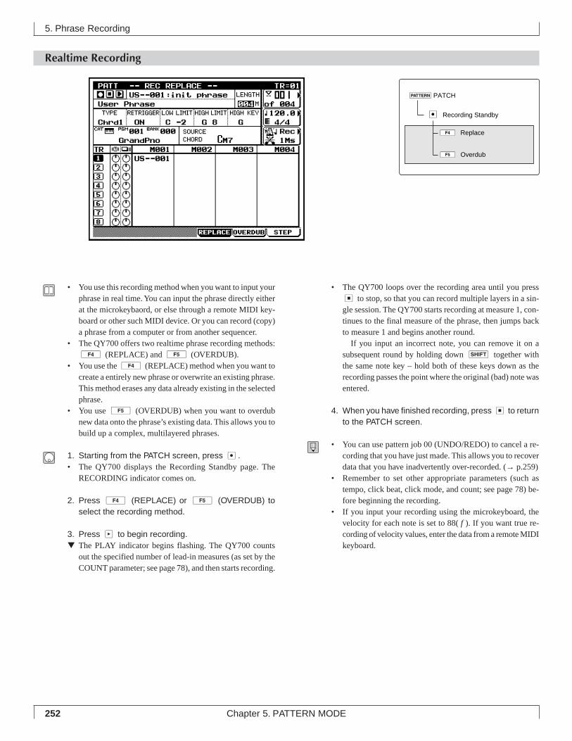
252 Chapter 5. PATTERN MODE
Realtime Recording
5. Phrase Recording
• You use this recording method when you want to input yourphrase in real time. You can input the phrase directly eitherat the microkeybaord, or else through a remote MIDI key-board or other such MIDI device. Or you can record (copy)a phrase from a computer or from another sequencer.
• The QY700 offers two realtime phrase recording methods:4 (REPLACE) and 5 (OVERDUB).
• You use the 4 (REPLACE) method when you want tocreate a entirely new phrase or overwrite an existing phrase.This method erases any data already existing in the selectedphrase.
• You use 5 (OVERDUB) when you want to overdubnew data onto the phrase’s existing data. This allows you tobuild up a complex, multilayered phrases.
1. Starting from the PATCH screen, press e.• The QY700 displays the Recording Standby page. The
RECORDING indicator comes on.
2. Press 4 (REPLACE) or 5 (OVERDUB) toselect the recording method.
3. Press p to begin recording.▼ The PLAY indicator begins flashing. The QY700 counts
out the specified number of lead-in measures (as set by theCOUNT parameter; see page 78), and then starts recording.
• The QY700 loops over the recording area until you presss to stop, so that you can record multiple layers in a sin-gle session. The QY700 starts recording at measure 1, con-tinues to the final measure of the phrase, then jumps backto measure 1 and begins another round.
If you input an incorrect note, you can remove it on asubsequent round by holding down s together withthe same note key – hold both of these keys down as therecording passes the point where the original (bad) note wasentered.
4. When you have finished recording, press s to returnto the PATCH screen.
• You can use pattern job 00 (UNDO/REDO) to cancel a re-cording that you have just made. This allows you to recoverdata that you have inadvertently over-recorded. (→ p.259)
• Remember to set other appropriate parameters (such astempo, click beat, click mode, and count; see page 78) be-fore beginning the recording.
• If you input your recording using the microkeyboard, thevelocity for each note is set to 88( f ). If you want true re-cording of velocity values, enter the data from a remote MIDIkeyboard.
4ÊReplace
5ÊOverdub
pPATCH
eÊRecording Standby
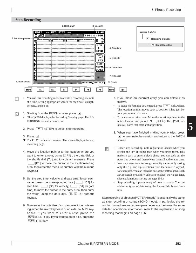
253Chapter 5. PATTERN MODE
5
Step Recording
7. If you make an incorrect entry, you can delete it asfollows.
• To delete the last note you entered, press 5 (BkDelete).The location pointer moves back to position it had just be-fore you entered that note.
• To delete some other note: Move the location pointer to thenote’s location and press 6 (Delete). The QY700 de-letes all notes that start at that position.
8. When you have finished making your entries, presss to terminate the session and return to the PATCHscreen.
• Under step recording, note registration occurs when yourelease the key(s), rather than when you press them. Thismakes it easy to enter a block chord: you can pick out thenotes one by one and then release them all at the same time.
• You may want to enter rough velocity values only (usingonly the f, p, and mp selections from the numeric keypad,for example). You can then use one of the pattern jobs (suchas Crescendo or Modify Velocity) to adjust the values later.(See explanations starting on page 256.)
• Step recording supports entry of note data only. You canadd other types of data using the Phrase Edit Insert func-tion.
Step recording of phrases (PATTERN mode) is essentially the sameas step recording of songs (SONG mode). In particular, the re-cording procedures and screen parameters are the same. For moredetailed operational information, refer to the explanation of songrecording that begins on page 106.
5. Phrase Recording
• You use this recording mode to create a recording one noteat a time, setting appropriate values for each note’s length,velocity, and so on.
1. Starting from the PATCH screen, press e.• The QY700 displays the Recording Standby page. The RE-
CORDING indicator comes on.
2. Press 6 (STEP) to select step recording.
3. Press p.▼ The PLAY indicator comes on. The screen displays the step
recording page.
4. Move the location pointer to the location where youwant to enter a note, using n/y, the data dial, orthe shuttle dial. (To jump to a distant measure: Pressd [D1] to move the cursor to the location-settingarea, then enter the measure number with the numerickeypad.)
5. Set the step time, velocity, and gate time. To set eachvalue, press the corresponding key (d [D2] forstep time, d [D3] for velocity, d [D4] for gatetime) to move the cursor to the entry area, then enterthe value using the data dial, n/y, or numerickeypad.
6. Now enter the note itself. You can select the note us-ing either the microkeyboard or an external MIDI key-board. If you want to enter a rest, press them(REST) key. If you want to enter a tie, press thes (TIE) key.
8. Back delete
SHIFT F1 F2 F3 F4 F5 F6 SHIFT EXIT
7. Piano roll
6. Gate time
5. Velocity
4. Step time
2. Location pointer
3. Location1. Beat graph
9. Delete
6Step Recording
pPATCH
eÊRecording Standby
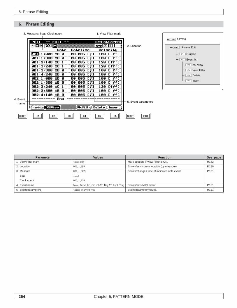
254 Chapter 5. PATTERN MODE
6. Phrase Editing
6. Phrase Editing
Mark appears if View Filter is ON.
Shows/sets cursor location (by measure).
Shows/changes time of indicated note event.
Shows/sets MIDI event.
Event parameter values.
View only
001,...,999
001,..., 999
1,...,8
000,...,239
Note, Bend, PC, CC, ChAT, KeyAT, Excl, Tmp
Varies by event type
1 View Filter mark
2 Location
3 Measure
Beat
Clock count
4 Event name
5 Event parameters
Parameter Values Function See pageP.132
P.130
P.131
P.131
P.131
SHIFT F1 F2 F3 F4 F5 F6 SHIFT EXIT
2. Location
3. Measure: Beat: Clock count 1. View Filter mark
4. Event name
5. Event parameters
eÊPhrase Edit
4View Filter
2XG View
5Delete
6Insert
pPATCH
1Graphic
1Event list
255Chapter 5. PATTERN MODE
5
• You use the PHRASE EDIT submode to edit the contentsof a user phrase. You can adjust or delete any of the MIDIevents that constitute the phrase, and you can add new events.
• The QY700 offers two different editing screens: an eventlist and a graphic display. You can toggle between thesescreens by pressing 1.
• The event list presents a listing of the track’s MIDI events,in order of their occurrence. Each entry shows an event’slocation in time, its name, and its numerical arguments. Youare free to adjust the location or any of the argument values.You can delete any of the events, or insert new ones.
• The graphic display consists of a piano-roll section and apoint-graph section. You can edit the event values on thisscreen, but you cannot insert or delete events. (→ p.135)
1. Go to the PATCH screen and select the user phrasethat you want to edit.
2. Press e to enter PHRASE EDIT submode (EventList screen).
3. Move the cursor to the event that you want to edit. Youcan use various methods, as follows.
• Press d [D1] to move the location entry area. Selectthe measure using the data dial, n/y, or the numerickeypad.
• Regardless of the cursor position, you can always move thecursor rapidly across the screen using the shuttle dial or ther/f keys. If you move the cursor more slowly with theshuttle dial, the QY700 will play out note events as the cur-sor passes.
• You can move up or down one event at a time by pressingu/d. Again, the QY700 will reproduce note events whenthe cursor lands on them.
4. When you reach an event that you want to edit, usel/r to move the cursor along the event line to eachvalue you want to change. Enter your changes usingthe data dial, n/y, or the numeric keypad. Regard-less of the entry method, you must press e to regis-ter the value.
▼ The new settings will blink on the screen until you presse to register them. If you move the cursor before youpress e, the original values will remain in effect.
5. When you have finished editing, press e to re-turn to the PATCH screen.
• If you make an error during editing, you can undo all edit-ing changes by executing the UNDO pattern job (job #00).(→ p.259)
• For detailed explanation of the editing procedures, refer tothe discussion of the SONG EDIT function, starting on page129. Phrase editing is essentially identical to song editing,with the following restrictions: (a) the phrase is recordedonto one track only, (b) the phrase cannot be longer thanthe pattern, and (c) phrase editing does not offer tempo-change settings.
6. Phrase Editing
256 Chapter 5. PATTERN MODE
7. Pattern Jobs
7. Pattern Jobs
00 Undo/Redo
30 Style Icon
jÊPATTERN JOB
pPATCH
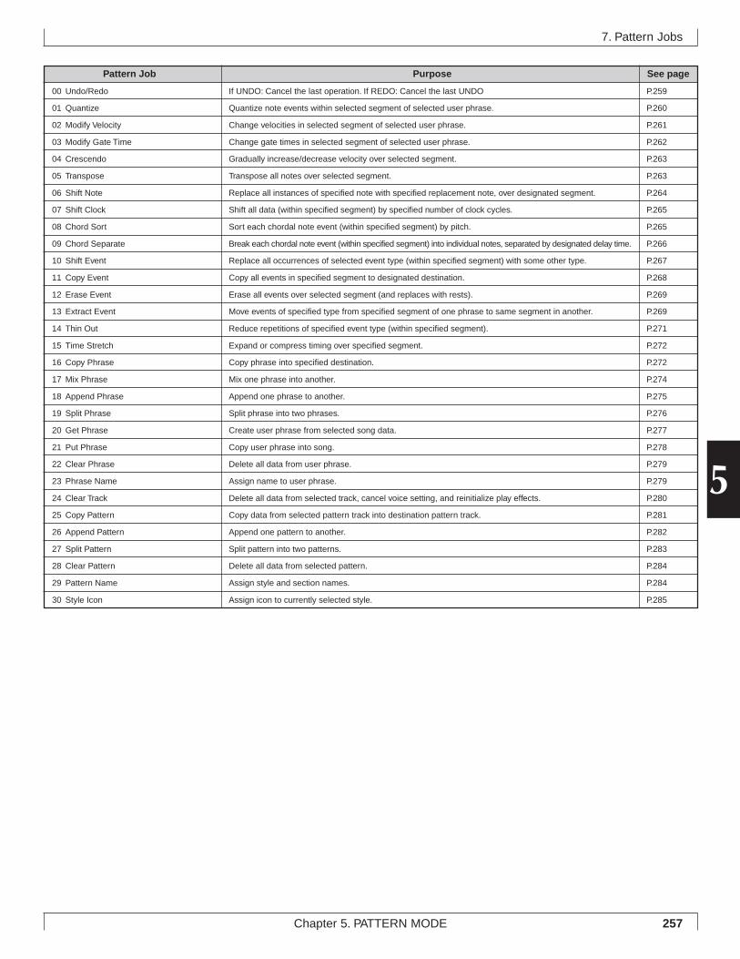
257Chapter 5. PATTERN MODE
5
7. Pattern Jobs
Pattern Job Purpose See page
00 Undo/Redo If UNDO: Cancel the last operation. If REDO: Cancel the last UNDO P.259
01 Quantize Quantize note events within selected segment of selected user phrase. P.260
02 Modify Velocity Change velocities in selected segment of selected user phrase. P.261
03 Modify Gate Time Change gate times in selected segment of selected user phrase. P.262
04 Crescendo Gradually increase/decrease velocity over selected segment. P.263
05 Transpose Transpose all notes over selected segment. P.263
06 Shift Note Replace all instances of specified note with specified replacement note, over designated segment. P.264
07 Shift Clock Shift all data (within specified segment) by specified number of clock cycles. P.265
08 Chord Sort Sort each chordal note event (within specified segment) by pitch. P.265
09 Chord Separate Break each chordal note event (within specified segment) into individual notes, separated by designated delay time. P.266
10 Shift Event Replace all occurrences of selected event type (within specified segment) with some other type. P.267
11 Copy Event Copy all events in specified segment to designated destination. P.268
12 Erase Event Erase all events over selected segment (and replaces with rests). P.269
13 Extract Event Move events of specified type from specified segment of one phrase to same segment in another. P.269
14 Thin Out Reduce repetitions of specified event type (within specified segment). P.271
15 Time Stretch Expand or compress timing over specified segment. P.272
16 Copy Phrase Copy phrase into specified destination. P.272
17 Mix Phrase Mix one phrase into another. P.274
18 Append Phrase Append one phrase to another. P.275
19 Split Phrase Split phrase into two phrases. P.276
20 Get Phrase Create user phrase from selected song data. P.277
21 Put Phrase Copy user phrase into song. P.278
22 Clear Phrase Delete all data from user phrase. P.279
23 Phrase Name Assign name to user phrase. P.279
24 Clear Track Delete all data from selected track, cancel voice setting, and reinitialize play effects. P.280
25 Copy Pattern Copy data from selected pattern track into destination pattern track. P.281
26 Append Pattern Append one pattern to another. P.282
27 Split Pattern Split pattern into two patterns. P.283
28 Clear Pattern Delete all data from selected pattern. P.284
29 Pattern Name Assign style and section names. P.284
30 Style Icon Assign icon to currently selected style. P.285
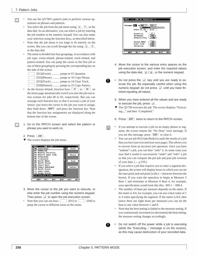
258 Chapter 5. PATTERN MODE
• You use the QY700’s pattern jobs to perform various op-erations on phrases and patterns.
• You select the job from the job menu using u, d, or thedata dial. As an alternative, you can select a job by enteringthe job number at the numeric keypad. You can also makeyour selection using the function keys, as described below.
• Note that the job menu is too large to fit entirely on thescreen. But you can scroll through the list using u, d,or the data dial.
• The menu is divided into four groupings, in accordance withjob type: event-related, phrase-related, track-related, andpattern-related. You can jump the cursor to the first job inany of these grouping by pressing the corresponding key onthe side of the screen.d [D1](Event) ............ jumps to 01 Quantize.d [D2](Phrase) .......... jumps to 16 Copy Phrase.d [D3](Track) ............ jumps to 24 Clear Track.d [D4](Pattern) .......... jumps to 25 Copy Pattern.
• As the factory default, function keys 1 to 6 onthe menu page automatically switch you into the job execu-tion screens for jobs 00 to 05, respectively. But you canreassign each function key so that it accesses a job of yourchoice: just move the cursor to the job you want to assign,then hold down s and press the function key. Notethat the function key assignments are displayed along thebottom line of the screen.
1. Go to the PATCH screen and select the pattern orphrase you want to work on.
2. Press j.▼ The screen displays the job menu.
3. Move the cursor to the job you want to execute, orelse enter the job number using the numeric keypad.Then press e to open the job-execution screen.
• Note that you can use keys d [D1] to d [D4] tojump the cursor to different areas on the menu.
4. Move the cursor to the various entry spaces on thejob execution screen, and enter the required valuesusing the data dial, n/y, or the numeric keypad.
• Do not press the e key until you are ready to ex-ecute the job. Be especially careful when using thenumeric keypad: do not press e until you have fin-ished inputting all values.
5. When you have entered all the values and are readyto execute the job, press e.
▼ The QY700 executes the job. The screen displays “Execut-ing...,” and then “Completed.”
6. Press e twice to return to the PATCH screen.
• If you attempt to execute a job on an empty phrase or seg-ment, the screen returns the “No Data” error message. Ifyou see this message, press e to clear it.
• You can use job 00 (Undo/Redo) to undo the results of a jobthat you have just executed (see next page). This allows youto recover from an incorrect job operation. Once you have“undone” a job, you can then “redo” it. In some cases youmay find it useful to successively “undo” and “redo” a jobso that you can compare the pre-job and post-job versionsof your data. (→ p.259.)
• If you select a job that requires you to enter a segment des-ignation, the screen will display boxes in which you can setthe start point and end point (with a ~ character between theboxes). If you want the operation to begin at Measure 5Beat 1 and terminate at Measure 8 Beat 4, for example,your specification would look like this: 005:1 ~ 008:4.
• The number of beats per measure depends on the meter. Ifthe meter is 4/4, for example, you can use a beat value of 1to 4 when specifying the segment. If the meter is 8/4, then(since there are eight beats per measure) you can set thebeat to any value between 1 and 8.
• Note that the beat setting is linked to the measure setting. Ifyou continuously increment (or decrement) the beat setting,the measure setting changes accordingly.
• Do not switch off the power while a job is executing(while the “Executing...” message is on the screen),as this may cause destruction of your recorded data.
7. Pattern Jobs
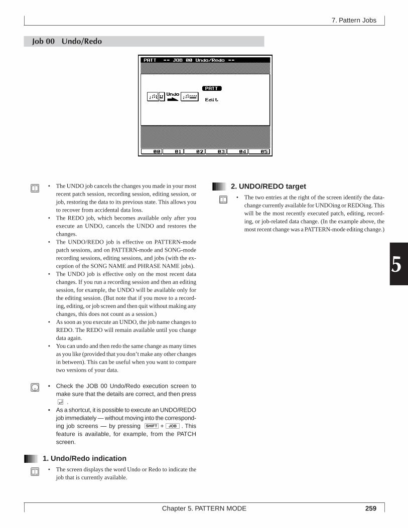
259Chapter 5. PATTERN MODE
5
Job 00 Undo/Redo
7. Pattern Jobs
2. UNDO/REDO target• The two entries at the right of the screen identify the data-
change currently available for UNDOing or REDOing. Thiswill be the most recently executed patch, editing, record-ing, or job-related data change. (In the example above, themost recent change was a PATTERN-mode editing change.)
• The UNDO job cancels the changes you made in your mostrecent patch session, recording session, editing session, orjob, restoring the data to its previous state. This allows youto recover from accidental data loss.
• The REDO job, which becomes available only after youexecute an UNDO, cancels the UNDO and restores thechanges.
• The UNDO/REDO job is effective on PATTERN-modepatch sessions, and on PATTERN-mode and SONG-moderecording sessions, editing sessions, and jobs (with the ex-ception of the SONG NAME and PHRASE NAME jobs).
• The UNDO job is effective only on the most recent datachanges. If you run a recording session and then an editingsession, for example, the UNDO will be available only forthe editing session. (But note that if you move to a record-ing, editing, or job screen and then quit without making anychanges, this does not count as a session.)
• As soon as you execute an UNDO, the job name changes toREDO. The REDO will remain available until you changedata again.
• You can undo and then redo the same change as many timesas you like (provided that you don’t make any other changesin between). This can be useful when you want to comparetwo versions of your data.
• Check the JOB 00 Undo/Redo execution screen tomake sure that the details are correct, and then presse .
• As a shortcut, it is possible to execute an UNDO/REDOjob immediately — without moving into the correspond-ing job screens — by pressing s+j. Thisfeature is available, for example, from the PATCHscreen.
1. Undo/Redo indication• The screen displays the word Undo or Redo to indicate the
job that is currently available.
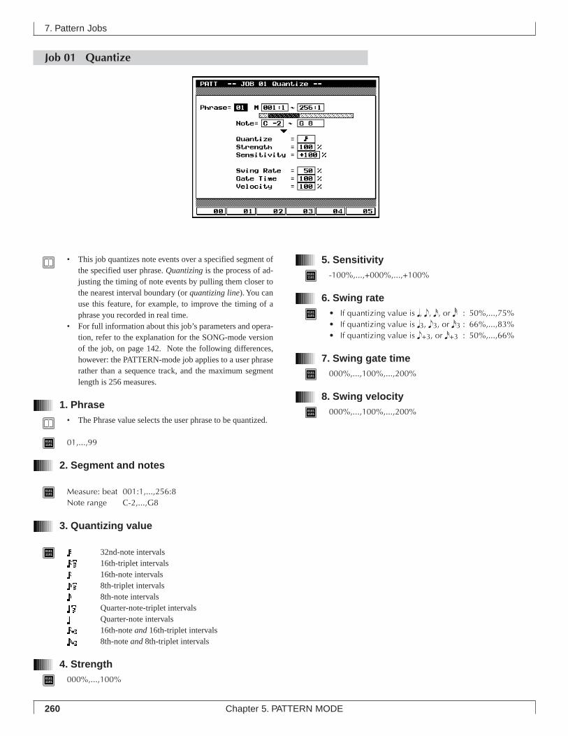
260 Chapter 5. PATTERN MODE
Job 01 Quantize
7. Pattern Jobs
• This job quantizes note events over a specified segment ofthe specified user phrase. Quantizing is the process of ad-justing the timing of note events by pulling them closer tothe nearest interval boundary (or quantizing line). You canuse this feature, for example, to improve the timing of aphrase you recorded in real time.
• For full information about this job’s parameters and opera-tion, refer to the explanation for the SONG-mode versionof the job, on page 142. Note the following differences,however: the PATTERN-mode job applies to a user phraserather than a sequence track, and the maximum segmentlength is 256 measures.
1. Phrase• The Phrase value selects the user phrase to be quantized.
01011101 01,...,99
2. Segment and notes
01011101 Measure: beat 001:1,...,256:8
Note range C-2,...,G8
3. Quantizing value
01011101 32nd-note intervals
16th-triplet intervals16th-note intervals8th-triplet intervals8th-note intervalsQuarter-note-triplet intervalsQuarter-note intervals16th-note and 16th-triplet intervals8th-note and 8th-triplet intervals
4. Strength01011101 000%,...,100%
5. Sensitivity01011101 -100%,...,+000%,...,+100%
6. Swing rate01011101 • If quantizing value is q, e, x, or r : 50%,...,75%
• If quantizing value is q3, e3, or x3 : 66%,...,83%• If quantizing value is e+3, or x+3 : 50%,...,66%
7. Swing gate time01011101 000%,...,100%,...,200%
8. Swing velocity01011101 000%,...,100%,...,200%
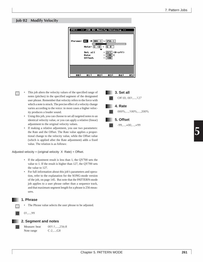
261Chapter 5. PATTERN MODE
5
3. Set all01011101 Off (0), 001,...,127
4. Rate01011101 000%,...,100%,...,200%
5. Offset01011101 -99,...,+00,...,+99
7. Pattern Jobs
Job 02 Modify Velocity
• This job alters the velocity values of the specified range ofnotes (pitches) in the specified segment of the designateduser phrase. Remember that velocity refers to the force withwhich a note is struck. The precise effect of a velocity changevaries according to the voice: in most cases a higher veloc-ity produces a louder sound.
• Using this job, you can choose to set all targeted notes to anidentical velocity value, or you can apply a relative (linear)adjustment to the original velocity values.
• If making a relative adjustment, you use two parameters:the Rate and the Offset. The Rate value applies a propor-tional change to the velocity value, while the Offset value(which is applied after the Rate adjustment) adds a fixedvalue. The relation is as follows:
Adjusted velocity = (original velocity X Rate) + Offset.
• If the adjustment result is less than 1, the QY700 sets thevalue to 1. If the result is higher than 127, the QY700 setsthe value to 127.
• For full information about this job’s parameters and opera-tion, refer to the explanation for the SONG-mode versionof the job, on page 145. But note that the PATTERN-modejob applies to a user phrase rather than a sequence track,and that maximum segment length for a phrase is 256 meas-ures.
1. Phrase• The Phrase value selects the user phrase to be adjusted.
01011101 01,...,99
2. Segment and notes01011101 Measure: beat 001:1,...,256:8
Note range C-2,...,G8
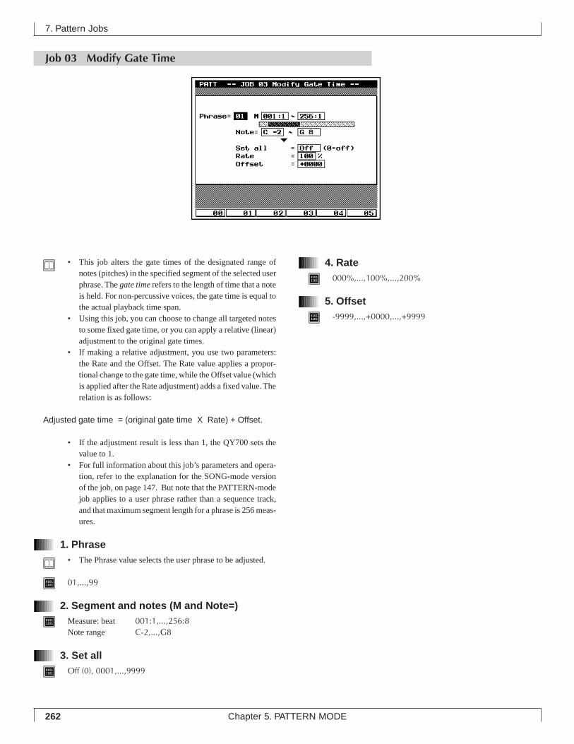
262 Chapter 5. PATTERN MODE
Job 03 Modify Gate Time
4. Rate01011101 000%,...,100%,...,200%
5. Offset01011101 -9999,...,+0000,...,+9999
7. Pattern Jobs
• This job alters the gate times of the designated range ofnotes (pitches) in the specified segment of the selected userphrase. The gate time refers to the length of time that a noteis held. For non-percussive voices, the gate time is equal tothe actual playback time span.
• Using this job, you can choose to change all targeted notesto some fixed gate time, or you can apply a relative (linear)adjustment to the original gate times.
• If making a relative adjustment, you use two parameters:the Rate and the Offset. The Rate value applies a propor-tional change to the gate time, while the Offset value (whichis applied after the Rate adjustment) adds a fixed value. Therelation is as follows:
Adjusted gate time = (original gate time X Rate) + Offset.
• If the adjustment result is less than 1, the QY700 sets thevalue to 1.
• For full information about this job’s parameters and opera-tion, refer to the explanation for the SONG-mode versionof the job, on page 147. But note that the PATTERN-modejob applies to a user phrase rather than a sequence track,and that maximum segment length for a phrase is 256 meas-ures.
1. Phrase• The Phrase value selects the user phrase to be adjusted.
01011101 01,...,99
2. Segment and notes (M and Note=)01011101 Measure: beat 001:1,...,256:8
Note range C-2,...,G8
3. Set all01011101 Off (0), 0001,...,9999
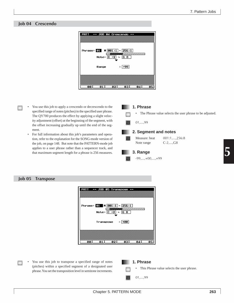
263Chapter 5. PATTERN MODE
5
Job 04 Crescendo
1. Phrase• The Phrase value selects the user phrase to be adjusted.
01011101 01,...,99
2. Segment and notes01011101 Measure: beat 001:1,...,256:8
Note range C-2,...,G8
3. Range01011101 -99,...,+00,...,+99
7. Pattern Jobs
• You use this job to apply a crescendo or decrescendo to thespecified range of notes (pitches) in the specified user phrase.The QY700 produces the effect by applying a slight veloc-ity adjustment (offset) at the beginning of the segment, withthe offset increasing gradually up until the end of the seg-ment.
• For full information about this job’s parameters and opera-tion, refer to the explanation for the SONG-mode version ofthe job, on page 148. But note that the PATTERN-mode jobapplies to a user phrase rather than a sequencer track, andthat maximum segment length for a phrase is 256 measures.
1. Phrase• This Phrase value selects the user phrase.
01011101 01,...,99
Job 05 Transpose
• You use this job to transpose a specified range of notes(pitches) within a specified segment of a designated userphrase. You set the transposition level in semitone increments.
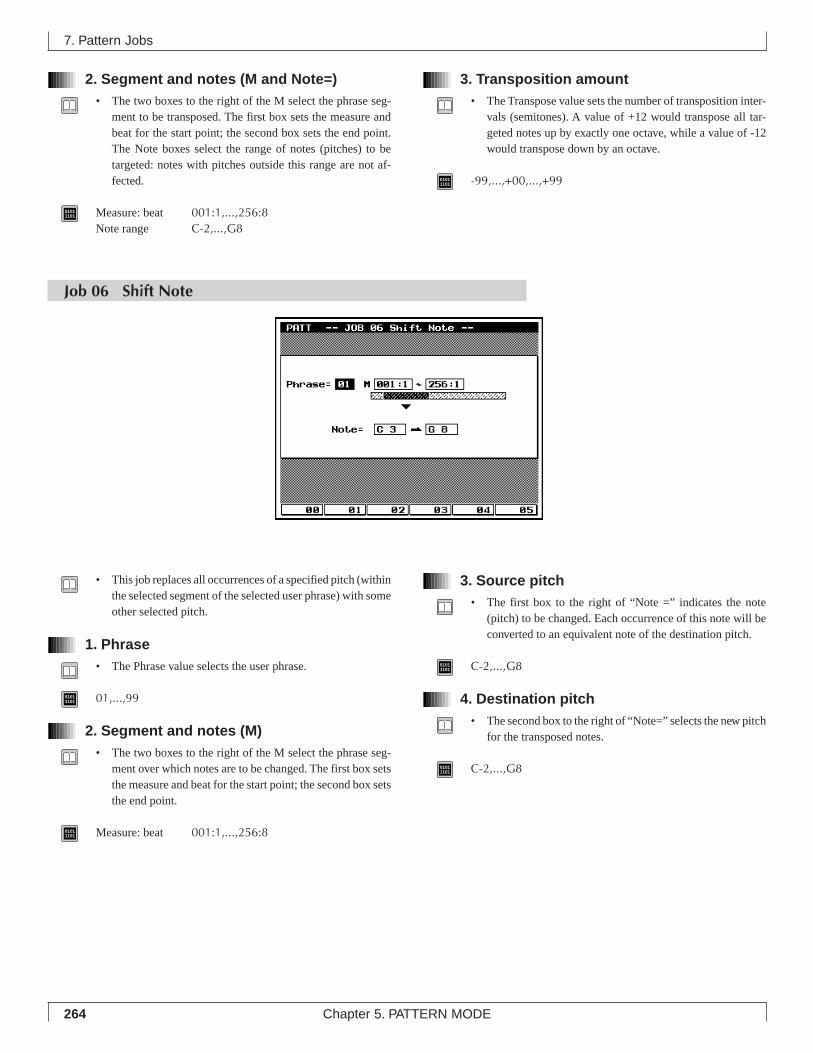
264 Chapter 5. PATTERN MODE
2. Segment and notes (M and Note=)• The two boxes to the right of the M select the phrase seg-
ment to be transposed. The first box sets the measure andbeat for the start point; the second box sets the end point.The Note boxes select the range of notes (pitches) to betargeted: notes with pitches outside this range are not af-fected.
01011101 Measure: beat 001:1,...,256:8
Note range C-2,...,G8
3. Transposition amount• The Transpose value sets the number of transposition inter-
vals (semitones). A value of +12 would transpose all tar-geted notes up by exactly one octave, while a value of -12would transpose down by an octave.
01011101 -99,...,+00,...,+99
7. Pattern Jobs
Job 06 Shift Note
• This job replaces all occurrences of a specified pitch (withinthe selected segment of the selected user phrase) with someother selected pitch.
1. Phrase• The Phrase value selects the user phrase.
01011101 01,...,99
2. Segment and notes (M)• The two boxes to the right of the M select the phrase seg-
ment over which notes are to be changed. The first box setsthe measure and beat for the start point; the second box setsthe end point.
01011101 Measure: beat 001:1,...,256:8
3. Source pitch• The first box to the right of “Note =” indicates the note
(pitch) to be changed. Each occurrence of this note will beconverted to an equivalent note of the destination pitch.
01011101 C-2,...,G8
4. Destination pitch• The second box to the right of “Note=” selects the new pitch
for the transposed notes.
01011101 C-2,...,G8
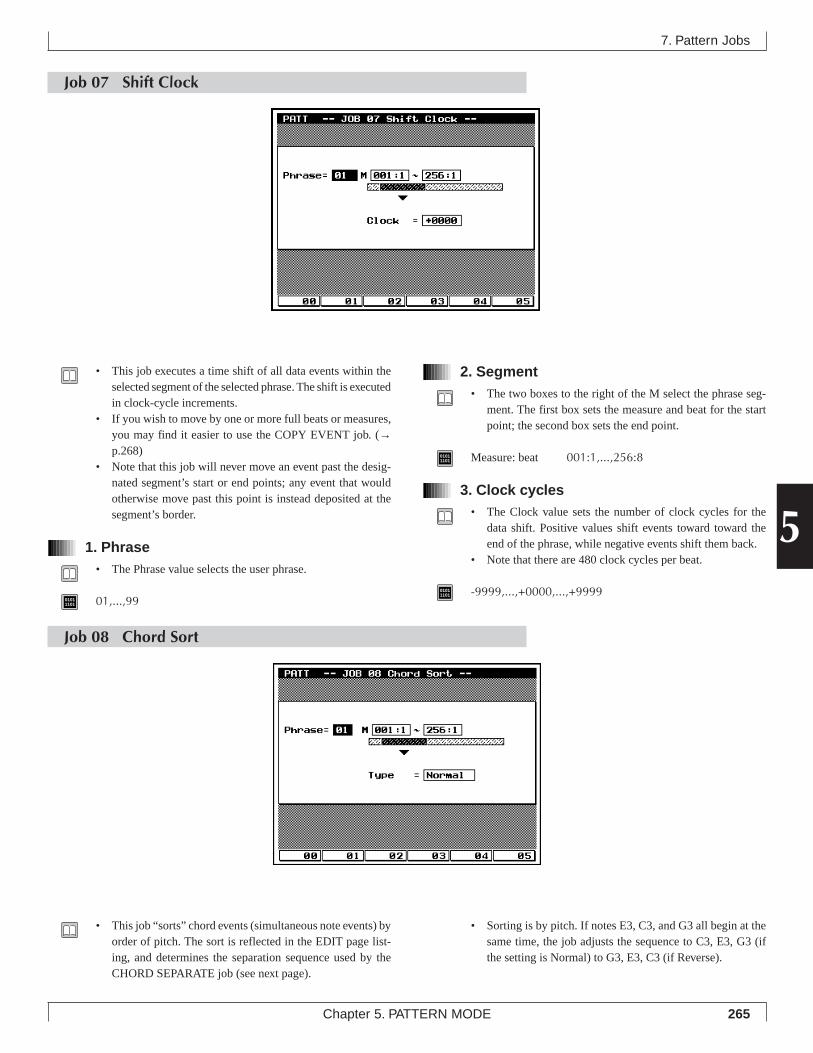
265Chapter 5. PATTERN MODE
5
Job 07 Shift Clock
2. Segment• The two boxes to the right of the M select the phrase seg-
ment. The first box sets the measure and beat for the startpoint; the second box sets the end point.
01011101 Measure: beat 001:1,...,256:8
3. Clock cycles• The Clock value sets the number of clock cycles for the
data shift. Positive values shift events toward toward theend of the phrase, while negative events shift them back.
• Note that there are 480 clock cycles per beat.
01011101 -9999,...,+0000,...,+9999
7. Pattern Jobs
• This job executes a time shift of all data events within theselected segment of the selected phrase. The shift is executedin clock-cycle increments.
• If you wish to move by one or more full beats or measures,you may find it easier to use the COPY EVENT job. (→p.268)
• Note that this job will never move an event past the desig-nated segment’s start or end points; any event that wouldotherwise move past this point is instead deposited at thesegment’s border.
1. Phrase• The Phrase value selects the user phrase.
01011101 01,...,99
Job 08 Chord Sort
• This job “sorts” chord events (simultaneous note events) byorder of pitch. The sort is reflected in the EDIT page list-ing, and determines the separation sequence used by theCHORD SEPARATE job (see next page).
• Sorting is by pitch. If notes E3, C3, and G3 all begin at thesame time, the job adjusts the sequence to C3, E3, G3 (ifthe setting is Normal) to G3, E3, C3 (if Reverse).
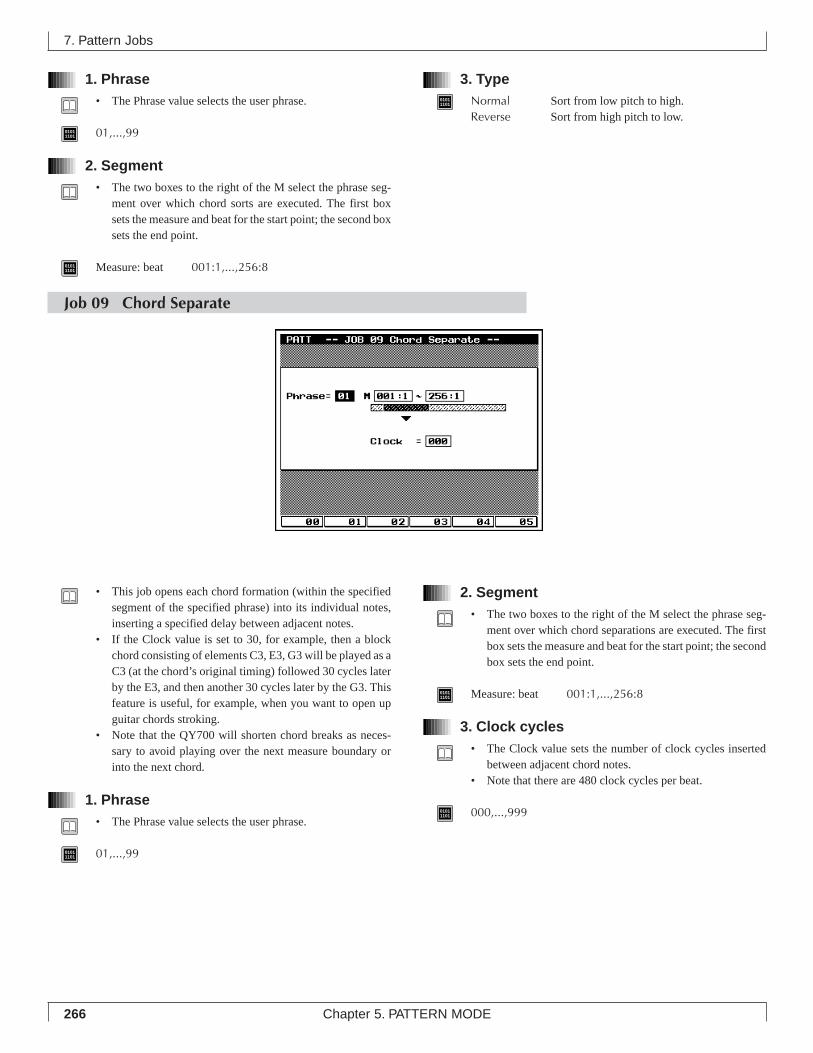
266 Chapter 5. PATTERN MODE
1. Phrase• The Phrase value selects the user phrase.
01011101 01,...,99
2. Segment• The two boxes to the right of the M select the phrase seg-
ment over which chord sorts are executed. The first boxsets the measure and beat for the start point; the second boxsets the end point.
01011101 Measure: beat 001:1,...,256:8
3. Type01011101 Normal Sort from low pitch to high.
Reverse Sort from high pitch to low.
7. Pattern Jobs
Job 09 Chord Separate
• This job opens each chord formation (within the specifiedsegment of the specified phrase) into its individual notes,inserting a specified delay between adjacent notes.
• If the Clock value is set to 30, for example, then a blockchord consisting of elements C3, E3, G3 will be played as aC3 (at the chord’s original timing) followed 30 cycles laterby the E3, and then another 30 cycles later by the G3. Thisfeature is useful, for example, when you want to open upguitar chords stroking.
• Note that the QY700 will shorten chord breaks as neces-sary to avoid playing over the next measure boundary orinto the next chord.
1. Phrase• The Phrase value selects the user phrase.
01011101 01,...,99
2. Segment• The two boxes to the right of the M select the phrase seg-
ment over which chord separations are executed. The firstbox sets the measure and beat for the start point; the secondbox sets the end point.
01011101 Measure: beat 001:1,...,256:8
3. Clock cycles• The Clock value sets the number of clock cycles inserted
between adjacent chord notes.• Note that there are 480 clock cycles per beat.
01011101 000,...,999
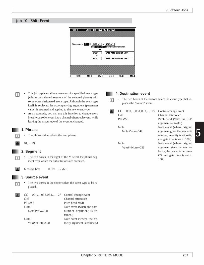
267Chapter 5. PATTERN MODE
5
4. Destination event• The two boxes at the bottom select the event type that re-
places the “source” event.
01011101 CC 001,...,031,033,...,127 Control-change event
CAT Channel aftertouchPB MSB Pitch bend (With the LSB
argument set to 00.)Note Note event (where original
argument gives the new notenumber; velocity is set to 64;and gate time is set to 108.)
Note Note event (where originalargument gives the new ve-locity; the new note becomesC3; and gate time is set to108.)
7. Pattern Jobs
Job 10 Shift Event
• This job replaces all occurrences of a specified event type(within the selected segment of the selected phrase) withsome other designated event type. Although the event typeitself is replaced, its accompanying argument (parametervalue) is retained and applied to the new event type.
• As an example, you can use this function to change everybreath-controller event into a channel-aftertouch event, whileleaving the magnitude of the event unchanged.
1. Phrase• The Phrase value selects the user phrase.
01011101 01,...,99
2. Segment• The two boxes to the right of the M select the phrase seg-
ment over which the substitutions are executed.
01011101 Measure:beat 001:1,...,256:8
3. Source event• The two boxes at the center select the event type to be re-
placed.
01011101 CC 001,...,031,033,...,127 Control-change event
CAT Channel aftertouchPB MSB Pitch bend MSBNote Note event (where the note-
number argument is re-tained.)
Note Note event (where the ve-locity argument is retained.)
Note (Velo=64)
Velo# (Note=C3)
Note (Velo=64)
Velo# (Note=C3)
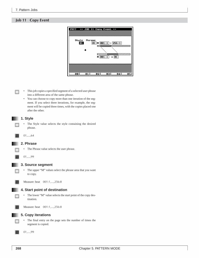
268 Chapter 5. PATTERN MODE
Job 11 Copy Event
7. Pattern Jobs
• This job copies a specified segment of a selected user phraseinto a different area of the same phrase.
• You can choose to copy more than one iteration of the seg-ment. If you select three iterations, for example, the seg-ment will be copied three times, with the copies placed oneafter the other.
1. Style• The Style value selects the style containing the desired
phrase.
01011101 01,...,64
2. Phrase• The Phrase value selects the user phrase.
01011101 01,...,99
3. Source segment• The upper “M” values select the phrase area that you want
to copy.
01011101 Measure: beat 001:1,...,256:8
4. Start point of destination• The lower “M” value selects the start point of the copy des-
tination.
01011101 Measure: beat 001:1,...,256:8
5. Copy iterations• The final entry on the page sets the number of times the
segment is copied.
01011101 01,...,99
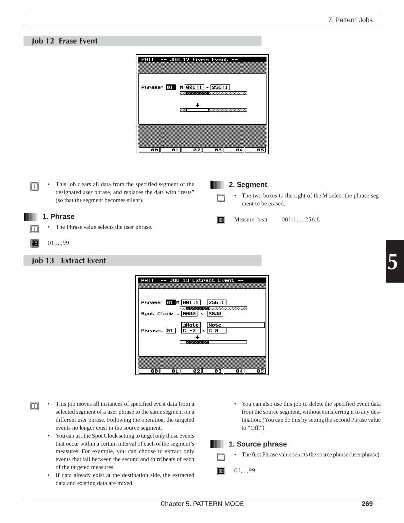
269Chapter 5. PATTERN MODE
5
7. Pattern Jobs
2. Segment• The two boxes to the right of the M select the phrase seg-
ment to be erased.
01011101 Measure: beat 001:1,...,256:8
Job 12 Erase Event
• This job clears all data from the specified segment of thedesignated user phrase, and replaces the data with “rests”(so that the segment becomes silent).
1. Phrase• The Phrase value selects the user phrase.
01011101 01,...,99
Job 13 Extract Event
• This job moves all instances of specified event data from aselected segment of a user phrase to the same segment on adifferent user phrase. Following the operation, the targetedevents no longer exist in the source segment.
• You can use the Spot Clock setting to target only those eventsthat occur within a certain interval of each of the segment’smeasures. For example, you can choose to extract onlyevents that fall between the second and third beats of eachof the targeted measures.
• If data already exist at the destination side, the extracteddata and existing data are mixed.
• You can also use this job to delete the specified event datafrom the source segment, without transferring it to any des-tination. (You can do this by setting the second Phrase valueto “Off.”)
1. Source phrase• The first Phrase value selects the source phrase (user phrase).
01011101 01,...,99
270 Chapter 5. PATTERN MODE
7. Pattern Jobs
2. Source segment• The two boxes to the right of the M select the source seg-
ment.
01011101 Measure: beat 001:1,...,256:16
3. Spot clock• The Spot Clock value selects the interval of each measure
from which data are to be extracted.• The interval is set by clock cycles, where each measure starts
at cycle 0000. There are 480 cycles per quarter note.• For example, assume that the meter is set to 4/4. In this
case, if you want to extract data only from the first half ofeach measure, you would set the range to 0000~0959. Ifyou wanted to copy only those events that fall exactly onthe fourth beat, you would set the range to 1440~1440.
01011101 0000,...,3840
4. Destination phrase• The second Phrase value selects the destination phrase (user
phrase).
01011101 Off, 01,...,99
Off No destination. (Erase only.)01,...,99 Selects destination phrase.
5. Event• The third pair of boxes (at the center of the screen) selects
the event type to be extracted.
01011101 Note, PC, PB, CC (000,...,127, All), CAT, PAT, EXC
Note Note events (C-2,...,G8, All)PC Program changePB Pitch bendCC(000,...,127,All) Control change (Any single control-
change message type 000 to 127, orall control-change messages)
CAT Channel aftertouchPAT Polyphonic aftertouchEXC System exclusive
6. Argument range• The lowest two boxes on the screen select the argument
range. The QY700 will extract only those events whose ar-gument falls within the specified range.
• If you are extracting note events, for example, you can usethis setting to limit extraction to all note events within acertain pitch range (for example, C3 to C4). If extractingprogram-change events, you can limit extraction to eventswith a certain range of program numbers.
• Note that the EXC event type does not accept an argument-range value.
• The values listed below show the maximum ranges. In allcases you can set a smaller range. Note that the first valueof the range must be less than or equal to the second value.
01011101 C-2,...,G8 Maximum range for note events.
-8192,...,+8191 Maximum range for pitchbend events.000,...,127 Maximum range for all event types
other than note and pitchbend.0000 0480 0960 1440 19194/4
0000 04800240 09600720 1200 1439
6/8
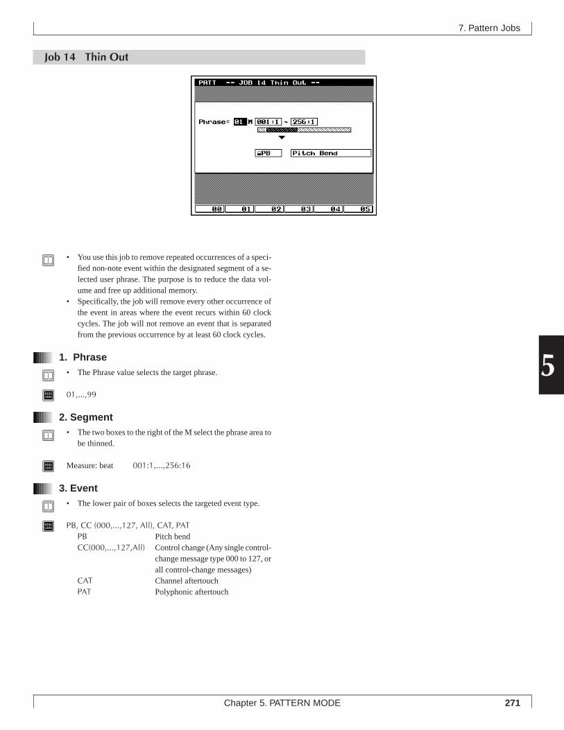
271Chapter 5. PATTERN MODE
5
Job 14 Thin Out
7. Pattern Jobs
• You use this job to remove repeated occurrences of a speci-fied non-note event within the designated segment of a se-lected user phrase. The purpose is to reduce the data vol-ume and free up additional memory.
• Specifically, the job will remove every other occurrence ofthe event in areas where the event recurs within 60 clockcycles. The job will not remove an event that is separatedfrom the previous occurrence by at least 60 clock cycles.
1. Phrase• The Phrase value selects the target phrase.
01011101 01,...,99
2. Segment• The two boxes to the right of the M select the phrase area to
be thinned.
01011101 Measure: beat 001:1,...,256:16
3. Event• The lower pair of boxes selects the targeted event type.
01011101 PB, CC (000,...,127, All), CAT, PAT
PB Pitch bendCC(000,...,127,All) Control change (Any single control-
change message type 000 to 127, orall control-change messages)
CAT Channel aftertouchPAT Polyphonic aftertouch
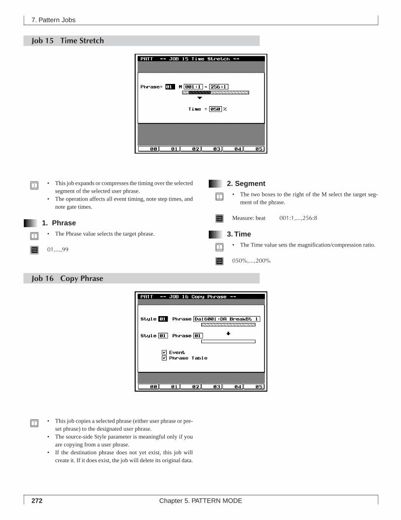
272 Chapter 5. PATTERN MODE
Job 15 Time Stretch
2. Segment• The two boxes to the right of the M select the target seg-
ment of the phrase.
01011101 Measure: beat 001:1,...,256:8
3. Time• The Time value sets the magnification/compression ratio.
01011101 050%,...,200%
• This job expands or compresses the timing over the selectedsegment of the selected user phrase.
• The operation affects all event timing, note step times, andnote gate times.
1. Phrase• The Phrase value selects the target phrase.
01011101 01,...,99
Job 16 Copy Phrase
• This job copies a selected phrase (either user phrase or pre-set phrase) to the designated user phrase.
• The source-side Style parameter is meaningful only if youare copying from a user phrase.
• If the destination phrase does not yet exist, this job willcreate it. If it does exist, the job will delete its original data.
7. Pattern Jobs
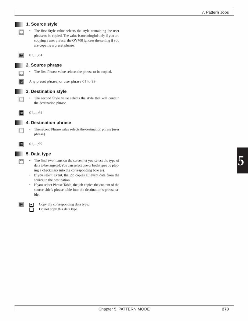
273Chapter 5. PATTERN MODE
5
1. Source style• The first Style value selects the style containing the user
phrase to be copied. The value is meaningful only if you arecopying a user phrase; the QY700 ignores the setting if youare copying a preset phrase.
01011101 01,...,64
2. Source phrase• The first Phrase value selects the phrase to be copied.
01011101 Any preset phrase, or user phrase 01 to 99
3. Destination style• The second Style value selects the style that will contain
the destination phrase.
01011101 01,...,64
4. Destination phrase• The second Phrase value selects the destination phrase (user
phrase).
01011101 01,...,99
5. Data type• The final two items on the screen let you select the type of
data to be targeted. You can select one or both types by plac-ing a checkmark into the corresponding box(es).
• If you select Event, the job copies all event data from thesource to the destination.
• If you select Phrase Table, the job copies the content of thesource side’s phrase table into the destination’s phrase ta-ble.
01011101 Copy the corresponding data type.
Do not copy this data type.
7. Pattern Jobs
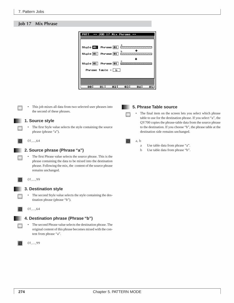
274 Chapter 5. PATTERN MODE
5. Phrase Table source• The final item on the screen lets you select which phrase
table to use for the destination phrase. If you select “a”, theQY700 copies the phrase-table data from the source phraseto the destination. If you choose “b”, the phrase table at thedestination side remains unchanged.
01011101 a, b
a Use table data from phrase “a”.b Use table data from phrase “b”.
7. Pattern Jobs
Job 17 Mix Phrase
• This job mixes all data from two selected user phrases intothe second of these phrases.
1. Source style• The first Style value selects the style containing the source
phrase (phrase “a”).
01011101 01,...,64
2. Source phrase (Phrase “a”)• The first Phrase value selects the source phrase. This is the
phrase containing the data to be mixed into the destinationphrase. Following the mix, the content of the source phraseremains unchanged.
01011101 01,...,99
3. Destination style• The second Style value selects the style containing the des-
tination phrase (phrase “b”).
01011101 01,...,64
4. Destination phrase (Phrase “b”)• The second Phrase value selects the destination phrase. The
original content of this phrase becomes mixed with the con-tent from phrase “a”.
01011101 01,...,99
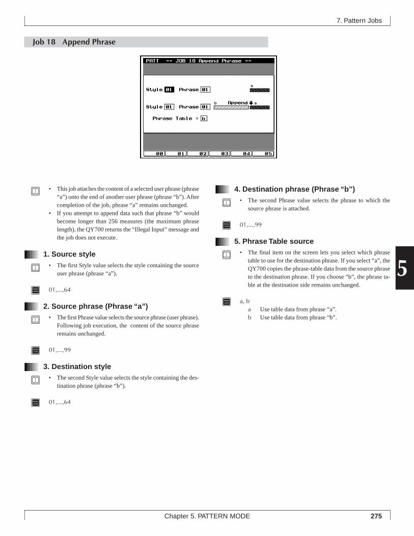
275Chapter 5. PATTERN MODE
5
4. Destination phrase (Phrase “b”)• The second Phrase value selects the phrase to which the
source phrase is attached.
01011101 01,...,99
5. Phrase Table source• The final item on the screen lets you select which phrase
table to use for the destination phrase. If you select “a”, theQY700 copies the phrase-table data from the source phraseto the destination phrase. If you choose “b”, the phrase ta-ble at the destination side remains unchanged.
01011101 a, b
a Use table data from phrase “a”.b Use table data from phrase “b”.
7. Pattern Jobs
Job 18 Append Phrase
• This job attaches the content of a selected user phrase (phrase“a”) onto the end of another user phrase (phrase “b”). Aftercompletion of the job, phrase “a” remains unchanged.
• If you attempt to append data such that phrase “b” wouldbecome longer than 256 measures (the maximum phraselength), the QY700 returns the “Illegal Input” message andthe job does not execute.
1. Source style• The first Style value selects the style containing the source
user phrase (phrase “a”).
01011101 01,...,64
2. Source phrase (Phrase “a”)• The first Phrase value selects the source phrase (user phrase).
Following job execution, the content of the source phraseremains unchanged.
01011101 01,...,99
3. Destination style• The second Style value selects the style containing the des-
tination phrase (phrase “b”).
01011101 01,...,64
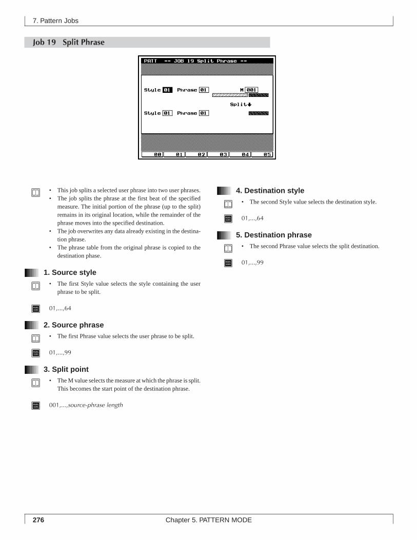
276 Chapter 5. PATTERN MODE
7. Pattern Jobs
4. Destination style• The second Style value selects the destination style.
01011101 01,...,64
5. Destination phrase• The second Phrase value selects the split destination.
01011101 01,...,99
Job 19 Split Phrase
• This job splits a selected user phrase into two user phrases.• The job splits the phrase at the first beat of the specified
measure. The initial portion of the phrase (up to the split)remains in its original location, while the remainder of thephrase moves into the specified destination.
• The job overwrites any data already existing in the destina-tion phrase.
• The phrase table from the original phrase is copied to thedestination phase.
1. Source style• The first Style value selects the style containing the user
phrase to be split.
01011101 01,...,64
2. Source phrase• The first Phrase value selects the user phrase to be split.
01011101 01,...,99
3. Split point• The M value selects the measure at which the phrase is split.
This becomes the start point of the destination phrase.
01011101 001,...,source-phrase length
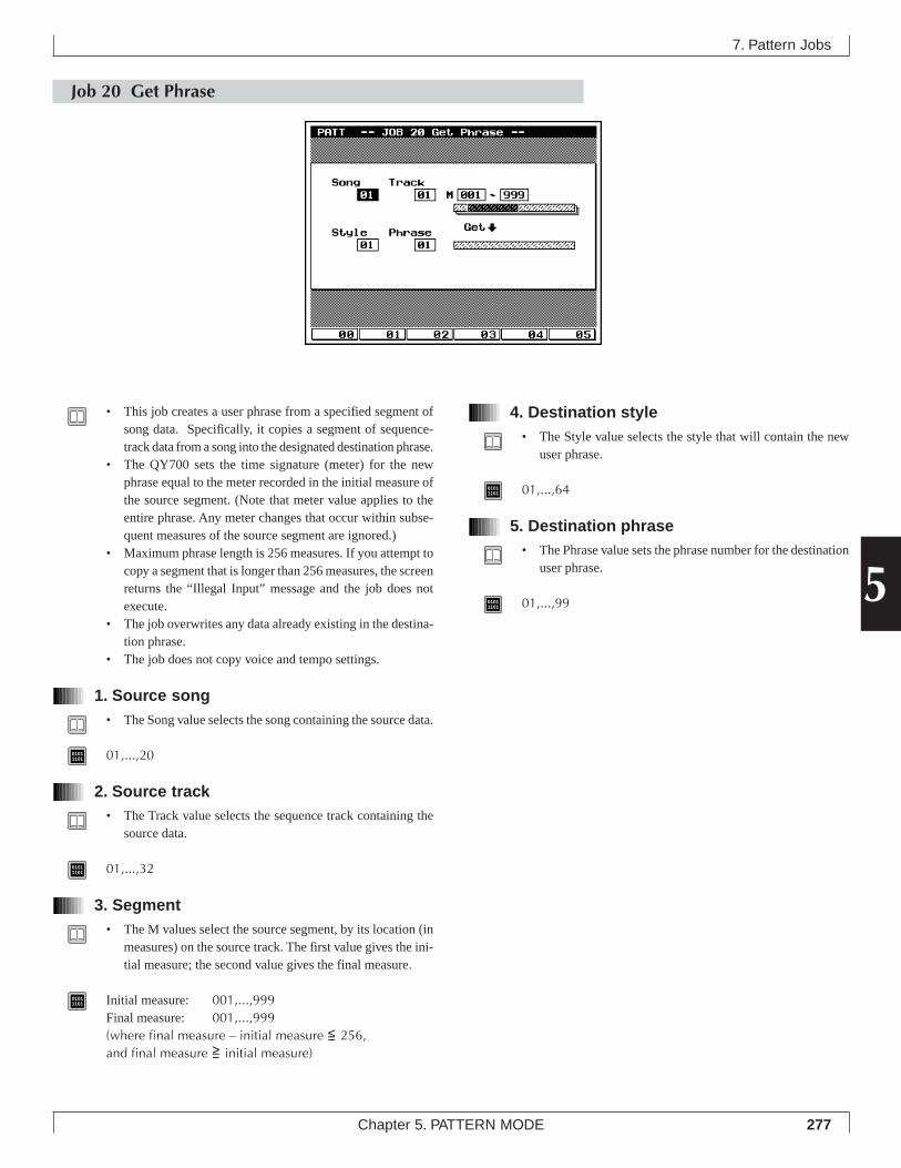
277Chapter 5. PATTERN MODE
5
7. Pattern Jobs
4. Destination style• The Style value selects the style that will contain the new
user phrase.
01011101 01,...,64
5. Destination phrase• The Phrase value sets the phrase number for the destination
user phrase.
01011101 01,...,99
Job 20 Get Phrase
• This job creates a user phrase from a specified segment ofsong data. Specifically, it copies a segment of sequence-track data from a song into the designated destination phrase.
• The QY700 sets the time signature (meter) for the newphrase equal to the meter recorded in the initial measure ofthe source segment. (Note that meter value applies to theentire phrase. Any meter changes that occur within subse-quent measures of the source segment are ignored.)
• Maximum phrase length is 256 measures. If you attempt tocopy a segment that is longer than 256 measures, the screenreturns the “Illegal Input” message and the job does notexecute.
• The job overwrites any data already existing in the destina-tion phrase.
• The job does not copy voice and tempo settings.
1. Source song• The Song value selects the song containing the source data.
01011101 01,...,20
2. Source track• The Track value selects the sequence track containing the
source data.
01011101 01,...,32
3. Segment• The M values select the source segment, by its location (in
measures) on the source track. The first value gives the ini-tial measure; the second value gives the final measure.
01011101 Initial measure: 001,...,999
Final measure: 001,...,999(where final measure – initial measure <= 256,and final measure >= initial measure)
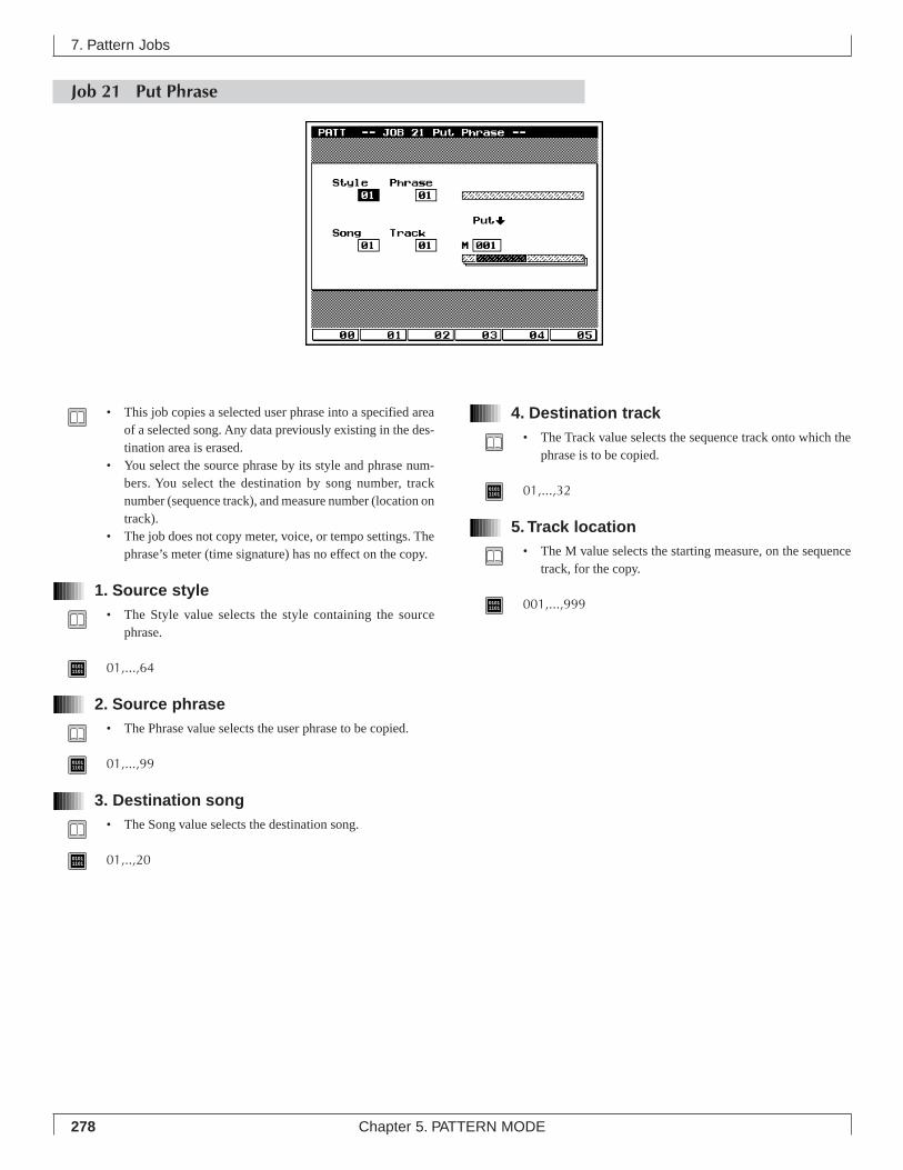
278 Chapter 5. PATTERN MODE
7. Pattern Jobs
Job 21 Put Phrase
• This job copies a selected user phrase into a specified areaof a selected song. Any data previously existing in the des-tination area is erased.
• You select the source phrase by its style and phrase num-bers. You select the destination by song number, tracknumber (sequence track), and measure number (location ontrack).
• The job does not copy meter, voice, or tempo settings. Thephrase’s meter (time signature) has no effect on the copy.
1. Source style• The Style value selects the style containing the source
phrase.
01011101 01,...,64
2. Source phrase• The Phrase value selects the user phrase to be copied.
01011101 01,...,99
3. Destination song• The Song value selects the destination song.
01011101 01,..,20
4. Destination track• The Track value selects the sequence track onto which the
phrase is to be copied.
01011101 01,...,32
5. Track location• The M value selects the starting measure, on the sequence
track, for the copy.
01011101 001,...,999
279Chapter 5. PATTERN MODE
5
Job 22 Clear Phrase
1. Phrase• The Phrase value selects the user phrase to be deleted.
01011101 01,...,99
• This job deletes all data from the selected user phrase, andreinitializes the phrase table.
Job 23 Phrase Name
• You use this job to set or change the name for a (non-empty)user phrase. The name can be up to 12 characters long.
1. Phrase• The Phrase value selects the user phrase to be named.• You cannot assign a name to an empty phrase. If you select
an empty phrase, a string of asterisks (************) ap-pears in the name entry area.
01011101 01,...,99
7. Pattern Jobs
280 Chapter 5. PATTERN MODE
2. Phrase name• Enter the phrase name into the entry space to the right of
the number.
01011101 Supported characters:
0,...,9, a,...,z, A,...,Z " ' ^ ( ) < = > @ | \ _ ! ? # $ % &* + - / , . : ; space
1. Move the cursor into the entry area.
2. Use the numeric keypad and the microkeyboard to in-put each character. Use the l and r keys to movethe cursor left and right as necessary.
• For information about how to input characters, refer to Chap-ter 1. (→ p.53)
3. When you have finished entering the name, presse twice to return to the PATCH screen. Move thecursor onto the phrase entry in the matrix, and checkthat the name appears correctly in the data-displayarea.
• Note that you do not need to press e to enter the name.
7. Pattern Jobs
Job 24 Clear Track
• This job deletes all data (of the selected type) from the se-lected pattern track, or from all pattern tracks.
1. Track• The TR setting selects the track to be cleared.
01011101 01,...,16, All
2. Data typeCheck the box containing the data type(s) that you want to de-lete.• If you select Patch, the job deletes all data stored in the
track.• If you select Play Effect, the job deletes all play-effect set-
tings for that track.• If you select Voice, the job deletes the track’s pattern-voice
setting.
01011101 Delete the corresponding data type.
Do not delete this data type.
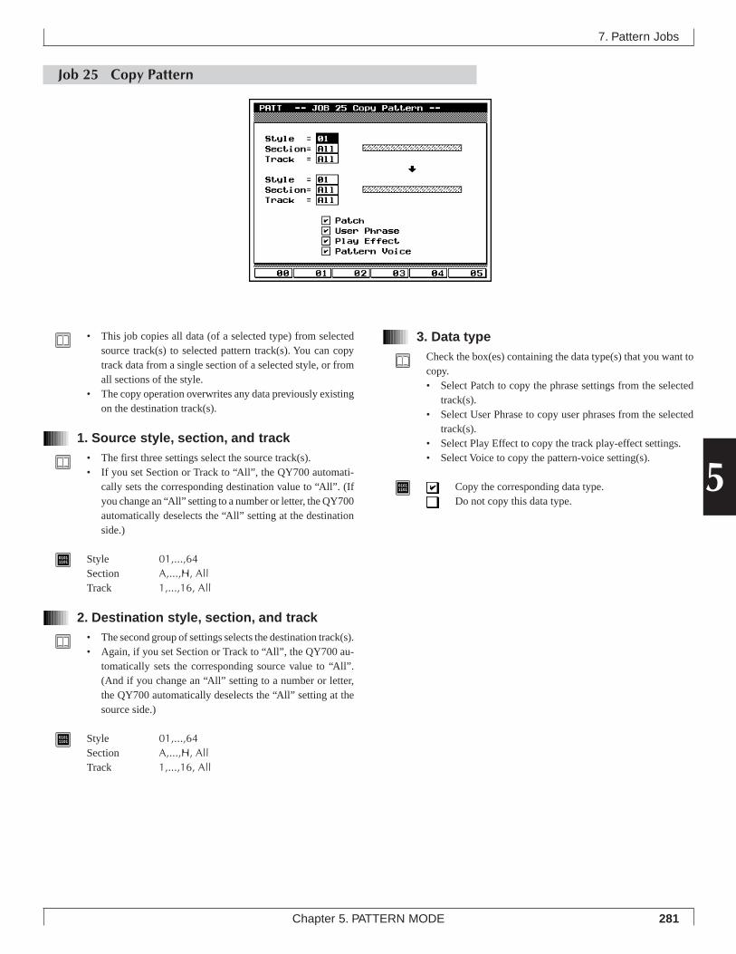
281Chapter 5. PATTERN MODE
5
3. Data typeCheck the box(es) containing the data type(s) that you want tocopy.• Select Patch to copy the phrase settings from the selected
track(s).• Select User Phrase to copy user phrases from the selected
track(s).• Select Play Effect to copy the track play-effect settings.• Select Voice to copy the pattern-voice setting(s).
01011101 Copy the corresponding data type.
Do not copy this data type.
7. Pattern Jobs
Job 25 Copy Pattern
• This job copies all data (of a selected type) from selectedsource track(s) to selected pattern track(s). You can copytrack data from a single section of a selected style, or fromall sections of the style.
• The copy operation overwrites any data previously existingon the destination track(s).
1. Source style, section, and track• The first three settings select the source track(s).• If you set Section or Track to “All”, the QY700 automati-
cally sets the corresponding destination value to “All”. (Ifyou change an “All” setting to a number or letter, the QY700automatically deselects the “All” setting at the destinationside.)
01011101 Style 01,...,64
Section A,...,H, AllTrack 1,...,16, All
2. Destination style, section, and track• The second group of settings selects the destination track(s).• Again, if you set Section or Track to “All”, the QY700 au-
tomatically sets the corresponding source value to “All”.(And if you change an “All” setting to a number or letter,the QY700 automatically deselects the “All” setting at thesource side.)
01011101 Style 01,...,64
Section A,...,H, AllTrack 1,...,16, All
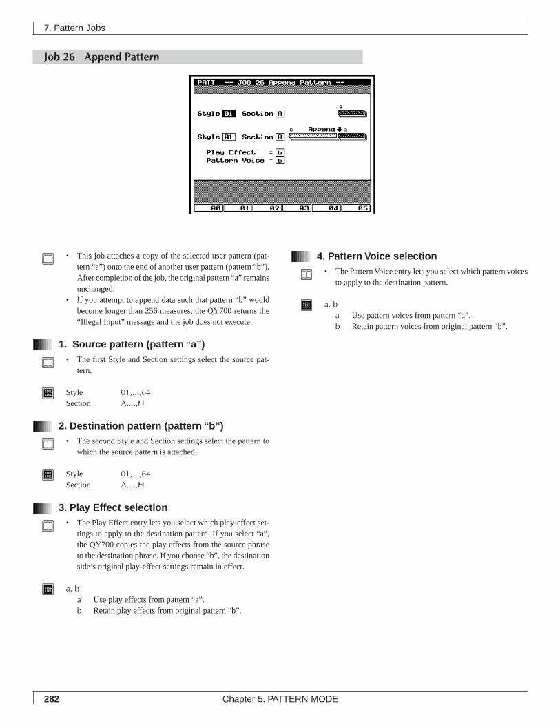
282 Chapter 5. PATTERN MODE
Job 26 Append Pattern
7. Pattern Jobs
4. Pattern Voice selection• The Pattern Voice entry lets you select which pattern voices
to apply to the destination pattern.
01011101 a, b
a Use pattern voices from pattern “a”.b Retain pattern voices from original pattern “b”.
• This job attaches a copy of the selected user pattern (pat-tern “a”) onto the end of another user pattern (pattern “b”).After completion of the job, the original pattern “a” remainsunchanged.
• If you attempt to append data such that pattern “b” wouldbecome longer than 256 measures, the QY700 returns the“Illegal Input” message and the job does not execute.
1. Source pattern (pattern “a”)• The first Style and Section settings select the source pat-
tern.
01011101 Style 01,...,64
Section A,...,H
2. Destination pattern (pattern “b”)• The second Style and Section settings select the pattern to
which the source pattern is attached.
01011101 Style 01,...,64
Section A,...,H
3. Play Effect selection• The Play Effect entry lets you select which play-effect set-
tings to apply to the destination pattern. If you select “a”,the QY700 copies the play effects from the source phraseto the destination phrase. If you choose “b”, the destinationside’s original play-effect settings remain in effect.
01011101 a, b
a Use play effects from pattern “a”.b Retain play effects from original pattern “b”.
283Chapter 5. PATTERN MODE
5
7. Pattern Jobs
3. Destination pattern• The second Style and Section select the new location for
the portion of the pattern that begins at the split point.
01011101 Style 01,...,64
Section A,...,H
4. Play Effect and Pattern Voice copy• The last two entries on the screen let you select whether or
not to copy the source’s play-effect and pattern-voice set-tings to the destination side when making the split.
01011101 Include the corresponding data.
Do not include this data.
Job 27 Split Pattern
• This job splits a selected pattern into two patterns.• The job splits the pattern at the first beat of the specified
measure. The initial portion of the pattern (up to the splitpoint) remains in its original location, while the portion start-ing after the split point is moved and becomes the destina-tion pattern. (If no phrases start after the split point, thedestination pattern becomes empty.)
• The job overwrites any data already existing in the destina-tion pattern.
1. Source pattern• The first Style and Section settings select the pattern to be
split.
01011101 Style 01,...,64
Section A,...,H
2. Split point• The M value selects the measure at which the pattern is
split. This becomes the start point of the destination phrase.
01011101 001,...,source-pattern length
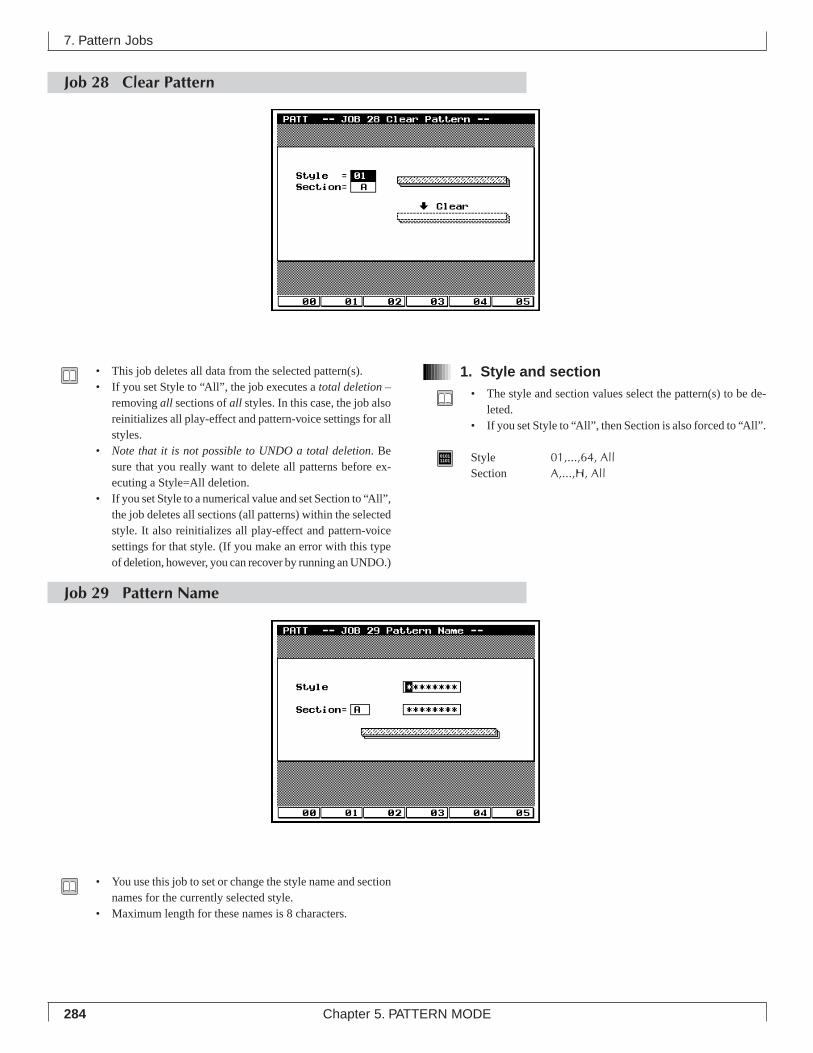
284 Chapter 5. PATTERN MODE
Job 28 Clear Pattern
7. Pattern Jobs
1. Style and section• The style and section values select the pattern(s) to be de-
leted.• If you set Style to “All”, then Section is also forced to “All”.
01011101 Style 01,...,64, All
Section A,...,H, All
• This job deletes all data from the selected pattern(s).• If you set Style to “All”, the job executes a total deletion –
removing all sections of all styles. In this case, the job alsoreinitializes all play-effect and pattern-voice settings for allstyles.
• Note that it is not possible to UNDO a total deletion. Besure that you really want to delete all patterns before ex-ecuting a Style=All deletion.
• If you set Style to a numerical value and set Section to “All”,the job deletes all sections (all patterns) within the selectedstyle. It also reinitializes all play-effect and pattern-voicesettings for that style. (If you make an error with this typeof deletion, however, you can recover by running an UNDO.)
Job 29 Pattern Name
• You use this job to set or change the style name and sectionnames for the currently selected style.
• Maximum length for these names is 8 characters.
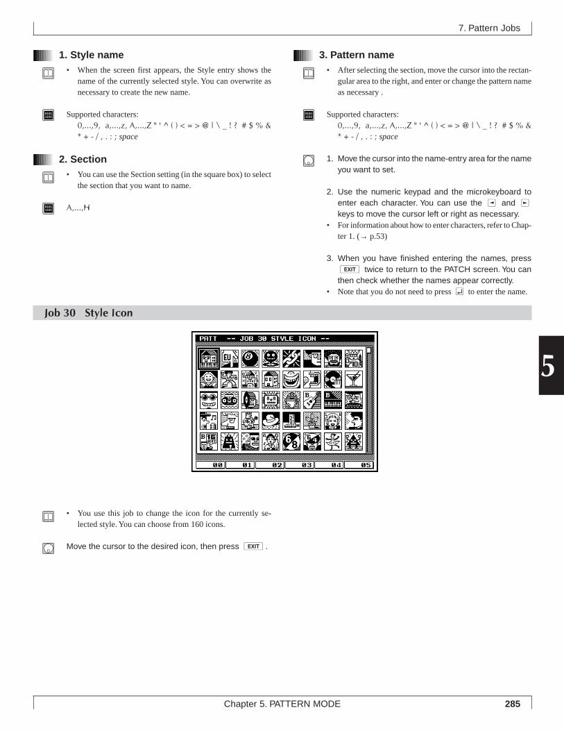
285Chapter 5. PATTERN MODE
5
7. Pattern Jobs
1. Style name• When the screen first appears, the Style entry shows the
name of the currently selected style. You can overwrite asnecessary to create the new name.
01011101 Supported characters:
0,...,9, a,...,z, A,...,Z " ' ^ ( ) < = > @ | \ _ ! ? # $ % &* + - / , . : ; space
2. Section• You can use the Section setting (in the square box) to select
the section that you want to name.
01011101 A,...,H
3. Pattern name• After selecting the section, move the cursor into the rectan-
gular area to the right, and enter or change the pattern nameas necessary .
01011101 Supported characters:
0,...,9, a,...,z, A,...,Z " ' ^ ( ) < = > @ | \ _ ! ? # $ % &* + - / , . : ; space
1. Move the cursor into the name-entry area for the nameyou want to set.
2. Use the numeric keypad and the microkeyboard toenter each character. You can use the l and rkeys to move the cursor left or right as necessary.
• For information about how to enter characters, refer to Chap-ter 1. (→ p.53)
3. When you have finished entering the names, presse twice to return to the PATCH screen. You canthen check whether the names appear correctly.
• Note that you do not need to press e to enter the name.
Job 30 Style Icon
• You use this job to change the icon for the currently se-lected style. You can choose from 160 icons.
Move the cursor to the desired icon, then press e.
286 Chapter 5. PATTERN MODE
Memo
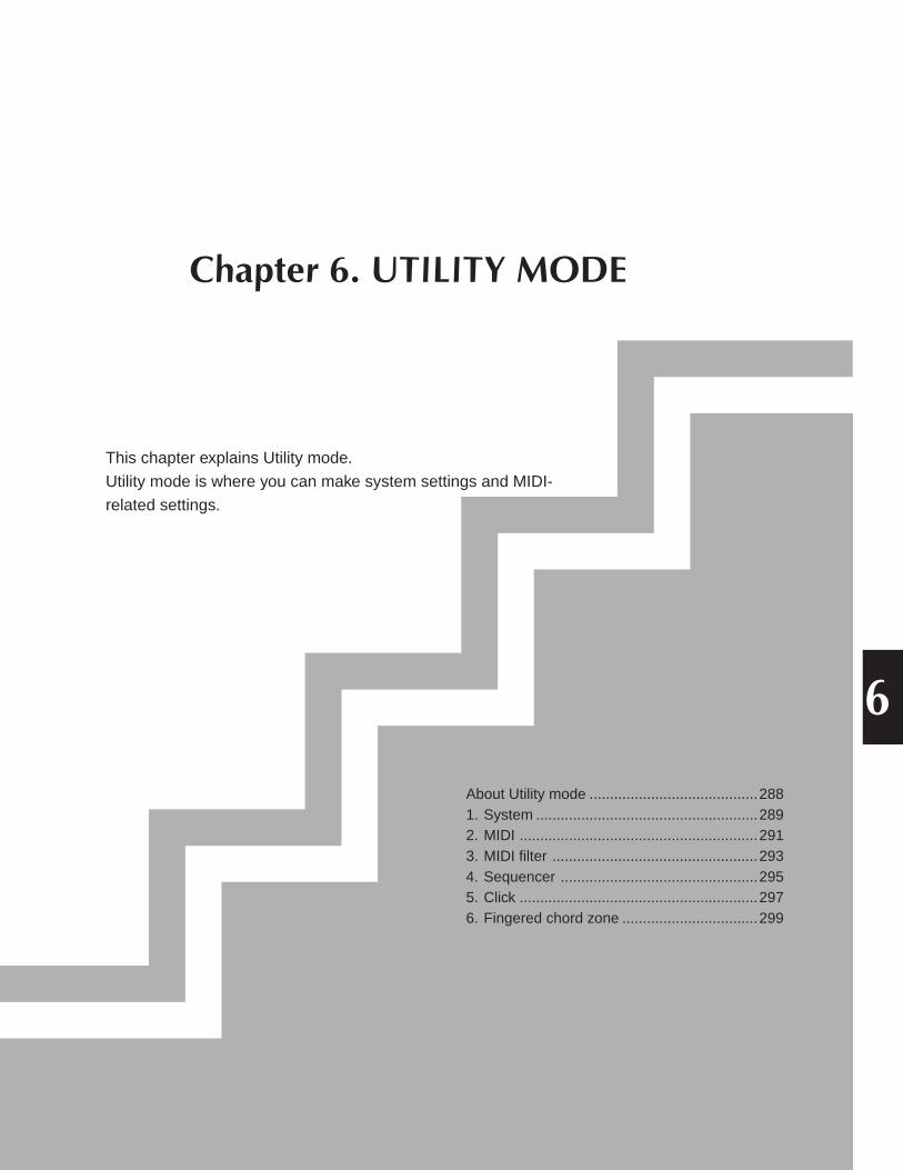
Chapter 6. UTILITY MODE
This chapter explains Utility mode.
Utility mode is where you can make system settings and MIDI-
related settings.
About Utility mode .........................................2881. System ......................................................2892. MIDI ..........................................................2913. MIDI filter ..................................................2934. Sequencer ................................................2955. Click ..........................................................2976. Fingered chord zone .................................299
6
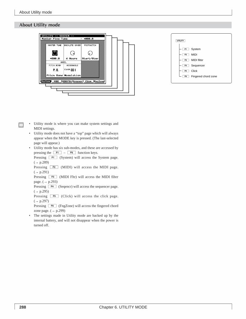
288 Chapter 6. UTILITY MODE
About Utility mode
About Utility mode
• Utility mode is where you can make system settings andMIDI settings.
• Utility mode does not have a “top” page which will alwaysappear when the MODE key is pressed. (The last-selectedpage will appear.)
• Utility mode has six sub-modes, and these are accessed bypressing the 1 – 6 function keys.Pressing 1 (System) will access the System page.(→ p.289)Pressing 2 (MIDI) will access the MIDI page.(→ p.291)Pressing 3 (MIDI Fltr) will access the MIDI filterpage. (→ p.293)Pressing 4 (Seqencr) will access the sequencer page.(→ p.295)Pressing 5 (Click) will access the click page.(→ p.297)Pressing 6 (FngZone) will access the fingered chordzone page. (→ p.299)
• The settings made in Utility mode are backed up by theinternal battery, and will not disappear when the power isturned off.
1ÊSystem
2ÊMIDI
3ÊMIDI filter
4ÊSequencer
5ÊClick
6ÊFingered chord zone
u
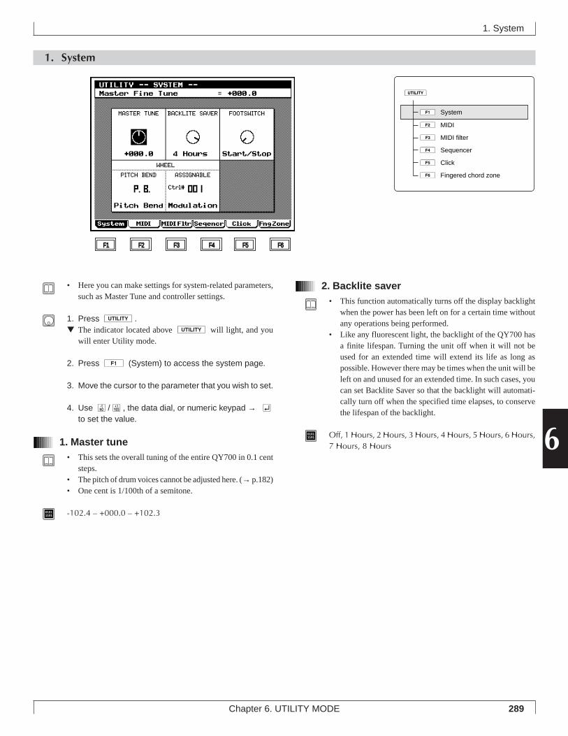
289Chapter 6. UTILITY MODE
6
1. System
2. Backlite saver• This function automatically turns off the display backlight
when the power has been left on for a certain time withoutany operations being performed.
• Like any fluorescent light, the backlight of the QY700 hasa finite lifespan. Turning the unit off when it will not beused for an extended time will extend its life as long aspossible. However there may be times when the unit will beleft on and unused for an extended time. In such cases, youcan set Backlite Saver so that the backlight will automati-cally turn off when the specified time elapses, to conservethe lifespan of the backlight.
01011101 Off, 1 Hours, 2 Hours, 3 Hours, 4 Hours, 5 Hours, 6 Hours,
7 Hours, 8 Hours
1. System
• Here you can make settings for system-related parameters,such as Master Tune and controller settings.
1. Press u.▼ The indicator located above u will light, and you
will enter Utility mode.
2. Press 1 (System) to access the system page.
3. Move the cursor to the parameter that you wish to set.
4. Use n/y, the data dial, or numeric keypad → eto set the value.
1. Master tune• This sets the overall tuning of the entire QY700 in 0.1 cent
steps.• The pitch of drum voices cannot be adjusted here. (→ p.182)• One cent is 1/100th of a semitone.
01011101 -102.4 – +000.0 – +102.3
F1 F2 F3 F4 F5 F6
1ÊSystem
2ÊMIDI
3ÊMIDI filter
4ÊSequencer
5ÊClick
6ÊFingered chord zone
u
290 Chapter 6. UTILITY MODE
3. Footswitch• This sets the function of the footswitch connected to the
rear panel FOOT SW connector.
01011101 Start/Stop, Section, Sustain, Sostenuto
Start/Stop Each time the footswitch is pressed, the songor pattern will alternately start or stop.
Section Each time the footswitch is pressed, the Sec-tion of the pattern will be switched in the or-der of A – H.
Sustain All notes played while the footswitch is heldwill be sustained until the footswitch is re-leased.
Sostenuto All notes which were being held on the key-board when the footswitch was pressed willbe sustained until the footswitch is released.
4. Pitch bend wheel, Assignable wheel• These settings specify the MIDI messages that are output
when the PITCH wheel and ASSIGNABLE wheel locatedon the QY700’s top panel are operated.
• Since the PITCH wheel will automatically return to thecenter position when it is released, it is suitable for control-ling Pitch Bend.
• The ASSIGNABLE wheel is detented in the center posi-tion.
01011101 OFF, P.B., Ctrl#001␣ – 119, CAT, VEL, TMP
OFFThe wheel will have no function.
P.B. (Pitch Bend)Pitch Bend messages.
Ctrl#001 (Modulation) – 119 (ContrlChng)Control Change messages. You can choose the controlnumber. However, Ctrl#032 cannot be selected.
CAT (Ch After)Channel aftertouch messages
VEL (Velocity)Velocity
TMP (Tempo)Tempo
1. System
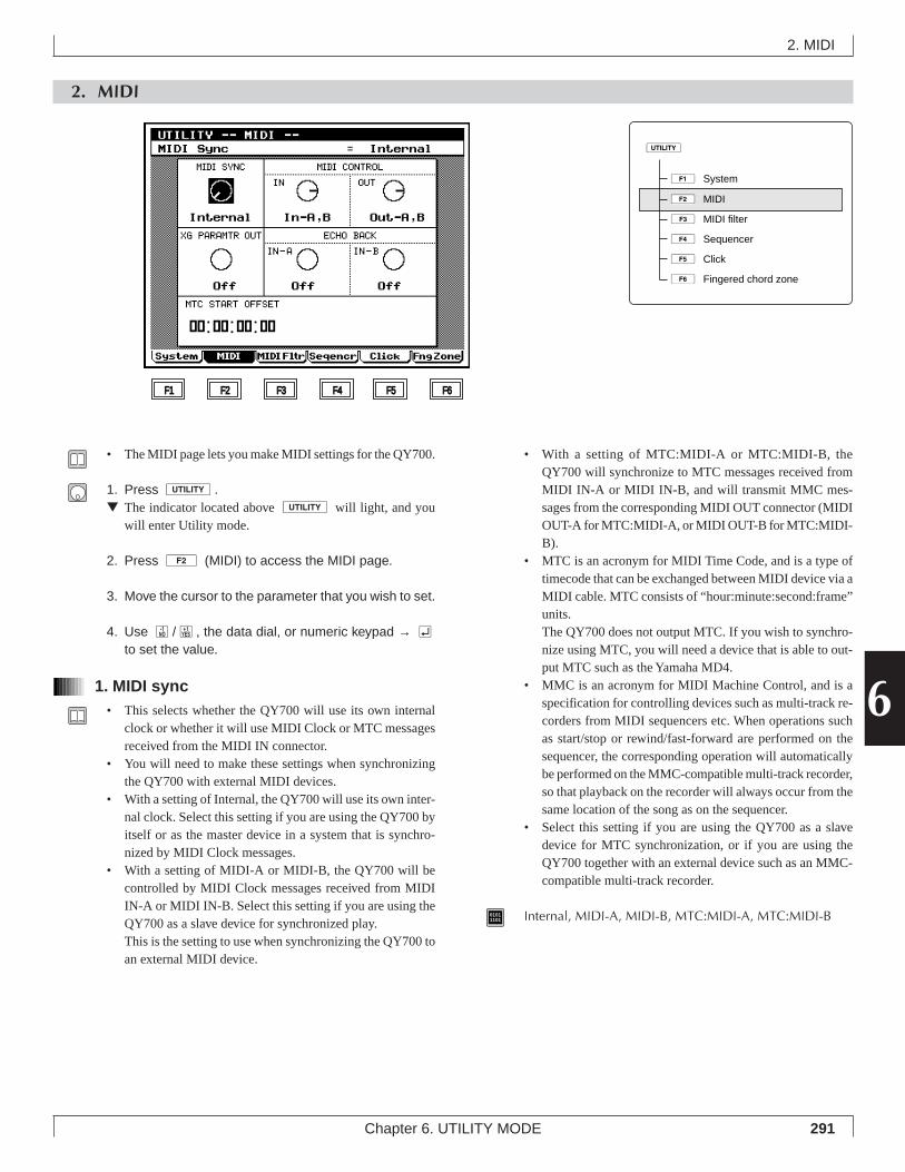
291Chapter 6. UTILITY MODE
6
2. MIDI
• With a setting of MTC:MIDI-A or MTC:MIDI-B, theQY700 will synchronize to MTC messages received fromMIDI IN-A or MIDI IN-B, and will transmit MMC mes-sages from the corresponding MIDI OUT connector (MIDIOUT-A for MTC:MIDI-A, or MIDI OUT-B for MTC:MIDI-B).
• MTC is an acronym for MIDI Time Code, and is a type oftimecode that can be exchanged between MIDI device via aMIDI cable. MTC consists of “hour:minute:second:frame”units.The QY700 does not output MTC. If you wish to synchro-nize using MTC, you will need a device that is able to out-put MTC such as the Yamaha MD4.
• MMC is an acronym for MIDI Machine Control, and is aspecification for controlling devices such as multi-track re-corders from MIDI sequencers etc. When operations suchas start/stop or rewind/fast-forward are performed on thesequencer, the corresponding operation will automaticallybe performed on the MMC-compatible multi-track recorder,so that playback on the recorder will always occur from thesame location of the song as on the sequencer.
• Select this setting if you are using the QY700 as a slavedevice for MTC synchronization, or if you are using theQY700 together with an external device such as an MMC-compatible multi-track recorder.
01011101 Internal, MIDI-A, MIDI-B, MTC:MIDI-A, MTC:MIDI-B
2. MIDI
• The MIDI page lets you make MIDI settings for the QY700.
1. Press u.▼ The indicator located above u will light, and you
will enter Utility mode.
2. Press 2 (MIDI) to access the MIDI page.
3. Move the cursor to the parameter that you wish to set.
4. Use n/y, the data dial, or numeric keypad → eto set the value.
1. MIDI sync• This selects whether the QY700 will use its own internal
clock or whether it will use MIDI Clock or MTC messagesreceived from the MIDI IN connector.
• You will need to make these settings when synchronizingthe QY700 with external MIDI devices.
• With a setting of Internal, the QY700 will use its own inter-nal clock. Select this setting if you are using the QY700 byitself or as the master device in a system that is synchro-nized by MIDI Clock messages.
• With a setting of MIDI-A or MIDI-B, the QY700 will becontrolled by MIDI Clock messages received from MIDIIN-A or MIDI IN-B. Select this setting if you are using theQY700 as a slave device for synchronized play.This is the setting to use when synchronizing the QY700 toan external MIDI device.
F1 F2 F3 F4 F5 F6
1ÊSystem
2ÊMIDI
3ÊMIDI filter
4ÊSequencer
5ÊClick
6ÊFingered chord zone
u
292 Chapter 6. UTILITY MODE
2. MIDI control in/out• These settings determine whether the MIDI messages Start,
Stop, Continue Start, Song Position/Pointer, and MIDI Clockwill be transmitted or received. (MIDI Clock is only trans-mitted.)
• MIDI Control In is the reception setting, and MIDI ControlOut is the transmission setting.
01011101 MIDI Control In
Off, In-A, In-B, In-A,BOff
Messages will not be received.In-A, In-B
Messages arriving at the MIDI IN-A connector or atthe MIDI IN-B connector will be received.
In-A,BMessage arriving at either the MIDI IN-A or the MIDIIN-B connector will be received.
MIDI Control OutOff, Out-A, Out-B, Out-A,B
OffMessages will not be transmitted.
Out-A, Out-BMessages will be transmitted from either the MIDIOUT-A connector or from the MIDI OUT-B connec-tor.
Out-A,BMessages will be transmitted from both the MIDIOUT-A and B connectors.
3. XG parameter out• When parameter values are modified in Voice mode or Ef-
fect mode, this setting specifies whether the operation willbe transmitted in realtime from the MIDI OUT connectorsas MIDI data.
• When using the QY700 together with another XG tone gen-erator, this setting allows the external XG tone generator’svoice and effect parameters to be controlled from the QY700.
01011101 Off, Out-A, Out-B, Out-A,B
Off MIDI will not be output.Out-A, Out-B MIDI will be output from the MIDI OUT-
A connector or from the MIDI OUT-B con-nector.
Out-A,B MIDI will be output from both the MIDIOUT-A and B connectors.
4. MIDI echo back In-A/In-B• Echo Back is a function by which data received at a MIDI
IN connector is re-transmitted from a MIDI OUT connec-tor. These parameters are the echo back settings.
• MIDI Echo Back In A sets echo back for data received atthe MIDI IN-A connector, and MIDI Echo Back In B fordata received at the MIDI IN-B connector.
• If you wish to use the QY700’s MIDI OUT connectors asMIDI THRU connectors, select Thru A, Thru B, or ThruA,B.
• When using an external MIDI keyboard and external MIDItone generator to record on QY700 tracks, selectRecMonitor.
• When connecting the QY700’s MIDI IN and MIDI OUTconnectors to an external MIDI device, select Off.
01011101 Off, Thru A, Thru B, Thru A,B, RecMonitor
OffEcho back will not be performed.
Thru A, Thru B, Thru A, BEcho back will be performed respectively from the MIDIOUT-A connector or the OUT-B connector, or from bothOUT-A and OUT-B connectors.
RecMonitorEcho back will be performed according to the Out Chan-nel MIDI OUT-A and MIDI OUT-B settings of the Key-board Track or the Recording Track.
• System exclusive messages of 128 bytes or longer will notbe echoed back.
5. MTC start offset• Specify the delay from when MIDI Time Code is received
until when the sequencer is started, in hours:minutes:seconds:frames.
• When synchronizing with an MTC-compatible MTR etc.,use this setting to make the song begin simultaneously.
01011101 hours:minutes:seconds:frames
Hours 00 – 23Minutes 00 – 59Seconds 00 – 59Frames 00 – 29
2. MIDI
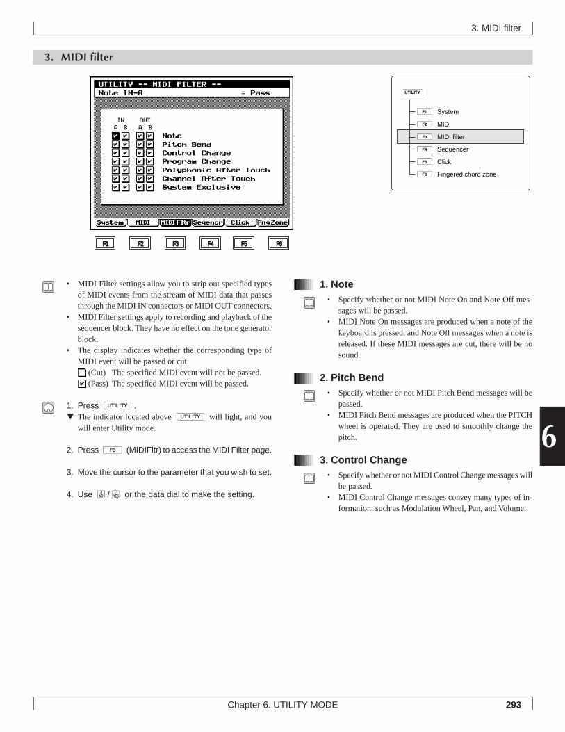
293Chapter 6. UTILITY MODE
6
3. MIDI filter
3. MIDI filter
• MIDI Filter settings allow you to strip out specified typesof MIDI events from the stream of MIDI data that passesthrough the MIDI IN connectors or MIDI OUT connectors.
• MIDI Filter settings apply to recording and playback of thesequencer block. They have no effect on the tone generatorblock.
• The display indicates whether the corresponding type ofMIDI event will be passed or cut.
(Cut) The specified MIDI event will not be passed. (Pass) The specified MIDI event will be passed.
1. Press u.▼ The indicator located above u will light, and you
will enter Utility mode.
2. Press 3 (MIDIFltr) to access the MIDI Filter page.
3. Move the cursor to the parameter that you wish to set.
4. Use n/y or the data dial to make the setting.
1. Note• Specify whether or not MIDI Note On and Note Off mes-
sages will be passed.• MIDI Note On messages are produced when a note of the
keyboard is pressed, and Note Off messages when a note isreleased. If these MIDI messages are cut, there will be nosound.
2. Pitch Bend• Specify whether or not MIDI Pitch Bend messages will be
passed.• MIDI Pitch Bend messages are produced when the PITCH
wheel is operated. They are used to smoothly change thepitch.
3. Control Change• Specify whether or not MIDI Control Change messages will
be passed.• MIDI Control Change messages convey many types of in-
formation, such as Modulation Wheel, Pan, and Volume.
F1 F2 F3 F4 F5 F6
1ÊSystem
2ÊMIDI
3ÊMIDI filter
4ÊSequencer
5ÊClick
6ÊFingered chord zone
u
294 Chapter 6. UTILITY MODE
4. Program Change• Specify whether or not MIDI Program Change messages
and the control change messages Bank Select MSB and LSBwill be passed.
• Program Change, and Bank Select MSB and LSB are MIDImessages used to select voices.
5. Polyphonic After Touch• Specify whether or not MIDI Polyphonic After Touch mes-
sages will be passed.
6. Channel Aftertouch• Specify whether or not MIDI Channel Aftertouch messages
will be passed.
7. System Exclusive• Specify whether or not MIDI System Exclusive messages
will be passed.• MIDI System Exclusive messages are used to reset the tone
generator and to operate internal parameters.
3. MIDI filter
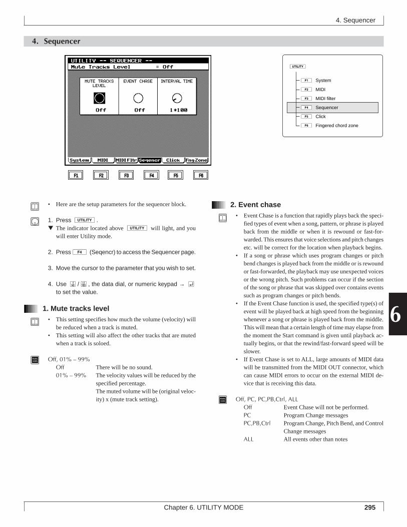
295Chapter 6. UTILITY MODE
6
2. Event chase• Event Chase is a function that rapidly plays back the speci-
fied types of event when a song, pattern, or phrase is playedback from the middle or when it is rewound or fast-for-warded. This ensures that voice selections and pitch changesetc. will be correct for the location when playback begins.
• If a song or phrase which uses program changes or pitchbend changes is played back from the middle or is rewoundor fast-forwarded, the playback may use unexpected voicesor the wrong pitch. Such problems can occur if the sectionof the song or phrase that was skipped over contains eventssuch as program changes or pitch bends.
• If the Event Chase function is used, the specified type(s) ofevent will be played back at high speed from the beginningwhenever a song or phrase is played back from the middle.This will mean that a certain length of time may elapse fromthe moment the Start command is given until playback ac-tually begins, or that the rewind/fast-forward speed will beslower.
• If Event Chase is set to ALL, large amounts of MIDI datawill be transmitted from the MIDI OUT connector, whichcan cause MIDI errors to occur on the external MIDI de-vice that is receiving this data.
01011101 Off, PC, PC,PB,Ctrl, ALL
Off Event Chase will not be performed.PC Program Change messagesPC,PB,Ctrl Program Change, Pitch Bend, and Control
Change messagesALL All events other than notes
4. Sequencer
• Here are the setup parameters for the sequencer block.
1. Press u.▼ The indicator located above u will light, and you
will enter Utility mode.
2. Press4 (Seqencr) to access the Sequencer page.
3. Move the cursor to the parameter that you wish to set.
4. Use n/y, the data dial, or numeric keypad → eto set the value.
1. Mute tracks level• This setting specifies how much the volume (velocity) will
be reduced when a track is muted.• This setting will also affect the other tracks that are muted
when a track is soloed.
01011101 Off, 01% – 99%
Off There will be no sound.01% – 99% The velocity values will be reduced by the
specified percentage.The muted volume will be (original veloc-ity) x (mute track setting).
4. Sequencer
F1 F2 F3 F4 F5 F6
1ÊSystem
2ÊMIDI
3ÊMIDI filter
4ÊSequencer
5ÊClick
6ÊFingered chord zone
u
296 Chapter 6. UTILITY MODE
3. Interval time• When system exclusive data (bulk data) recorded in a se-
quence track is played back, an interval of the duration speci-fied by this setting will be inserted between each 1 KB (kilo-byte) of data.
• When bulk data that was recorded is re-transmitted to anexternal MIDI device, limitations of the receiving device’sbulk data processing power may result in MIDI errors. Bysetting an appropriate Interval Time, you can transmit bulkdata at a rate that the receiving device is able to process.
• In sequence tracks, each unit of system exclusive data isrecorded in a single location of time. However when thisdata is played back, the Interval Time function will insert adelay between each 1 KB of data. The delay is specified inunits of 100 ms (1/10 second).
• If MIDI errors occur on the receiving device, increase theInterval Time setting and try transmitting the data again.
01011101 0 – 9 * 100 (msec)
• Interval Time settings may cause playback to be delayed.
4. Sequencer
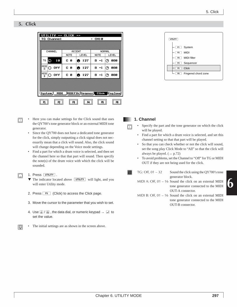
297Chapter 6. UTILITY MODE
6
5. Click
5. Click
• Here you can make settings for the Click sound that usesthe QY700’s tone generator block or an external MIDI tonegenerator.
• Since the QY700 does not have a dedicated tone generatorfor the click, simply outputting a click signal does not nec-essarily mean that a click will sound. Also, the click soundwill change depending on the Voice mode settings.
• Find a part for which a drum voice is selected, and then setthe channel here so that that part will sound. Then specifythe note(s) of the drum voice with which the click will besounded.
1. Press u.▼ The indicator located above u will light, and you
will enter Utility mode.
2. Press5 (Click) to access the Click page.
3. Move the cursor to the parameter that you wish to set.
4. Usen/y, the data dial, or numeric keypad → e toset the value.
• The initial settings are as shown in the screen above.
1. Channel• Specify the part and the tone generator on which the click
will be played.• Find a part for which a drum voice is selected, and set this
channel setting so that that part will be played.• So that you can check whether or not the click will sound,
set the song play Click Mode to “All” so that the click willalways be played. (→ p.72)
• To avoid problems, set the Channel to “Off” for TG or MIDIOUT if they are not being used for the click.
01011101 TG: Off, 01 – 32 Sound the click using the QY700’s tone
generator block.MIDI A: Off, 01 – 16 Sound the click on an external MIDI
tone generator connected to the MIDIOUT-A connector.
MIDI B: Off, 01 – 16 Sound the click on an external MIDItone generator connected to the MIDIOUT-B connector.
F1 F2 F3 F4 F5 F6
1ÊSystem
2ÊMIDI
3ÊMIDI filter
4ÊSequencer
5ÊClick
6ÊFingered chord zone
u
298 Chapter 6. UTILITY MODE
2. Accent note/level3. Normal note/level
• Accent specifies the click note and level for the first beat,and Normal specifies the click note and level for the secondand later beats.
• If you are using a drum voice to sound the click, you canuse the Note setting to select instruments within the drumvoice.
• For the correspondence between notes and instrument, re-fer to the separate “QY700 Reference Listings”.
• Level sets the volume by specifying the velocity.
01011101 Note C-2 – G8
Level 000 – 127
5. Click
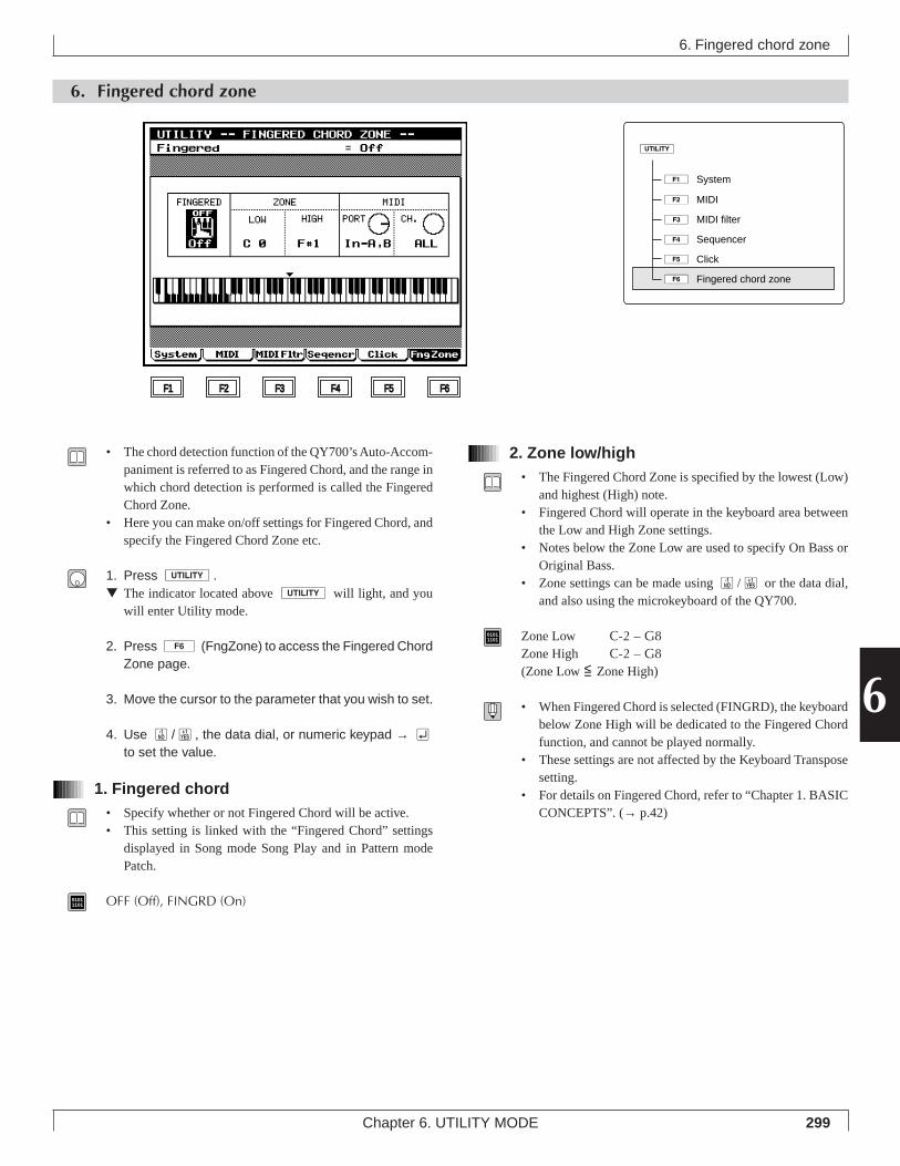
299Chapter 6. UTILITY MODE
6
6. Fingered chord zone
6. Fingered chord zone
• The chord detection function of the QY700’s Auto-Accom-paniment is referred to as Fingered Chord, and the range inwhich chord detection is performed is called the FingeredChord Zone.
• Here you can make on/off settings for Fingered Chord, andspecify the Fingered Chord Zone etc.
1. Press u.▼ The indicator located above u will light, and you
will enter Utility mode.
2. Press 6 (FngZone) to access the Fingered ChordZone page.
3. Move the cursor to the parameter that you wish to set.
4. Use n/y, the data dial, or numeric keypad → eto set the value.
1. Fingered chord• Specify whether or not Fingered Chord will be active.• This setting is linked with the “Fingered Chord” settings
displayed in Song mode Song Play and in Pattern modePatch.
01011101 OFF (Off), FINGRD (On)
2. Zone low/high• The Fingered Chord Zone is specified by the lowest (Low)
and highest (High) note.• Fingered Chord will operate in the keyboard area between
the Low and High Zone settings.• Notes below the Zone Low are used to specify On Bass or
Original Bass.• Zone settings can be made using n/y or the data dial,
and also using the microkeyboard of the QY700.
01011101 Zone Low C-2 – G8
Zone High C-2 – G8(Zone Low <= Zone High)
• When Fingered Chord is selected (FINGRD), the keyboardbelow Zone High will be dedicated to the Fingered Chordfunction, and cannot be played normally.
• These settings are not affected by the Keyboard Transposesetting.
• For details on Fingered Chord, refer to “Chapter 1. BASICCONCEPTS”. (→ p.42)
F1 F2 F3 F4 F5 F6
1ÊSystem
2ÊMIDI
3ÊMIDI filter
4ÊSequencer
5ÊClick
6ÊFingered chord zone
u
300 Chapter 6. UTILITY MODE
6. Fingered chord zone
3. MIDI port/channel• When using an external MIDI keyboard for Fingered Chord
input, specify the MIDI IN connector(s) to which the key-board is connected.
01011101 MIDI Port In-A, In-B, In-A,B
MIDI Channel ALL, 01 – 16
Chapter 7. DISK MODE
This chapter explains Disk mode.
Disk mode is where data can be transferred to and from floppy disk.
About floppy disks ........................................ 302About Disk mode .......................................... 3041. Save ......................................................... 3072. Load ......................................................... 3103. Rename ................................................... 3124. Delete....................................................... 3145. Format ...................................................... 316
7
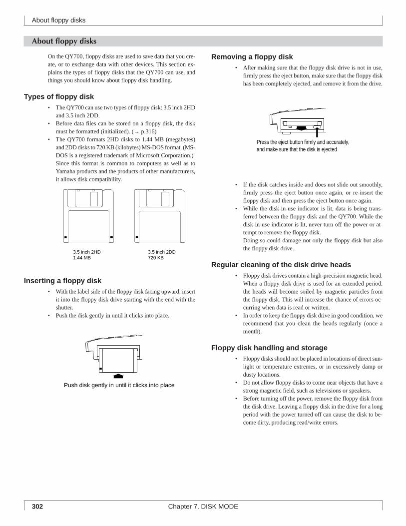
302 Chapter 7. DISK MODE
About floppy disks
About floppy disks
Removing a floppy disk• After making sure that the floppy disk drive is not in use,
firmly press the eject button, make sure that the floppy diskhas been completely ejected, and remove it from the drive.
• If the disk catches inside and does not slide out smoothly,firmly press the eject button once again, or re-insert thefloppy disk and then press the eject button once again.
• While the disk-in-use indicator is lit, data is being trans-ferred between the floppy disk and the QY700. While thedisk-in-use indicator is lit, never turn off the power or at-tempt to remove the floppy disk.Doing so could damage not only the floppy disk but alsothe floppy disk drive.
Regular cleaning of the disk drive heads• Floppy disk drives contain a high-precision magnetic head.
When a floppy disk drive is used for an extended period,the heads will become soiled by magnetic particles fromthe floppy disk. This will increase the chance of errors oc-curring when data is read or written.
• In order to keep the floppy disk drive in good condition, werecommend that you clean the heads regularly (once amonth).
Floppy disk handling and storage• Floppy disks should not be placed in locations of direct sun-
light or temperature extremes, or in excessively damp ordusty locations.
• Do not allow floppy disks to come near objects that have astrong magnetic field, such as televisions or speakers.
• Before turning off the power, remove the floppy disk fromthe disk drive. Leaving a floppy disk in the drive for a longperiod with the power turned off can cause the disk to be-come dirty, producing read/write errors.
On the QY700, floppy disks are used to save data that you cre-ate, or to exchange data with other devices. This section ex-plains the types of floppy disks that the QY700 can use, andthings you should know about floppy disk handling.
Types of floppy disk• The QY700 can use two types of floppy disk: 3.5 inch 2HD
and 3.5 inch 2DD.• Before data files can be stored on a floppy disk, the disk
must be formatted (initialized). (→ p.316)• The QY700 formats 2HD disks to 1.44 MB (megabytes)
and 2DD disks to 720 KB (kilobytes) MS-DOS format. (MS-DOS is a registered trademark of Microsoft Corporation.)Since this format is common to computers as well as toYamaha products and the products of other manufacturers,it allows disk compatibility.
Inserting a floppy disk• With the label side of the floppy disk facing upward, insert
it into the floppy disk drive starting with the end with theshutter.
• Push the disk gently in until it clicks into place.
3.5 inch 2HD1.44 MB
3.5 inch 2DD720 KB
Push disk gently in until it clicks into place
Press the eject button firmly and accurately, and make sure that the disk is ejected
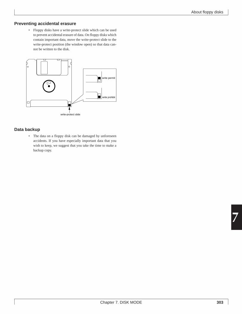
303Chapter 7. DISK MODE
7
About floppy disks
Preventing accidental erasure• Floppy disks have a write-protect slide which can be used
to prevent accidental erasure of data. On floppy disks whichcontain important data, move the write-protect slide to thewrite-protect position (the window open) so that data can-not be written to the disk.
Data backup• The data on a floppy disk can be damaged by unforeseen
accidents. If you have especially important data that youwish to keep, we suggest that you take the time to make abackup copy.
write-protect slide
write permit
write prohibit
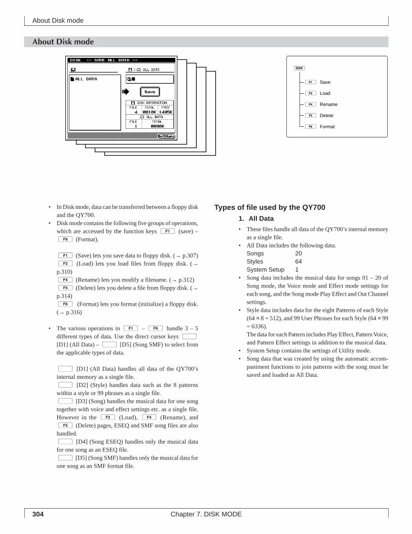
304 Chapter 7. DISK MODE
About Disk mode
Types of file used by the QY7001. All Data
• These files handle all data of the QY700’s internal memoryas a single file.
• All Data includes the following data.Songs 20Styles 64System Setup 1
• Song data includes the musical data for songs 01 – 20 ofSong mode, the Voice mode and Effect mode settings foreach song, and the Song mode Play Effect and Out Channelsettings.
• Style data includes data for the eight Patterns of each Style(64 × 8 = 512), and 99 User Phrases for each Style (64 × 99= 6336).The data for each Pattern includes Play Effect, Pattern Voice,and Pattern Effect settings in addition to the musical data.
• System Setup contains the settings of Utility mode.• Song data that was created by using the automatic accom-
paniment functions to join patterns with the song must besaved and loaded as All Data.
About Disk mode
• In Disk mode, data can be transferred between a floppy diskand the QY700.
• Disk mode contains the following five groups of operations,which are accessed by the function keys 1 (save) –6 (Format).
1 (Save) lets you save data to floppy disk. (→ p.307)2 (Load) lets you load files from floppy disk. (→p.310)4 (Rename) lets you modify a filename. (→ p.312)5 (Delete) lets you delete a file from floppy disk. (→p.314)6 (Format) lets you format (initialize) a floppy disk.(→ p.316)
• The various operations in 1 – 6 handle 3 – 5different types of data. Use the direct cursor keys d
[D1] (All Data) – d [D5] (Song SMF) to select fromthe applicable types of data.
d [D1] (All Data) handles all data of the QY700’sinternal memory as a single file.d [D2] (Style) handles data such as the 8 patternswithin a style or 99 phrases as a single file.d [D3] (Song) handles the musical data for one songtogether with voice and effect settings etc. as a single file.However in the 2 (Load), 4 (Rename), and5 (Delete) pages, ESEQ and SMF song files are alsohandled.d [D4] (Song ESEQ) handles only the musical datafor one song as an ESEQ file.d [D5] (Song SMF) handles only the musical data forone song as an SMF format file.
1ÊSave
2ÊLoad
4ÊRename
5ÊDelete
6ÊFormat
d
305Chapter 7. DISK MODE
7
2. Style
• Style files contain all the data included in a style of Patternmode.
• Style files contain the following data.Patterns 8 (sections)User Phrases 99 (user phrases)
• Pattern data also contains the Play Effect, Pattern Voice,and Pattern Effect settings in addition to the musical data.
3. Song
• Song files handle all data included in one song of Song modeas a single file.
• Song files include the following data.Musical data recorded in the songPattern track, Chord track, and Tempo track dataPlay Effect, Out Channel settingsVoice mode settingsEffect mode settings
4. Song ESEQ
• ESEQ is a sequencer format developed by Yamaha that isused on many Yamaha products including digital musicalinstruments such as the QY300 and QS300, Clavinovas andpiano players. ESEQ-compatible models can exchange se-quence data via floppy disk. (If you plan to exchange datawith another Yamaha product, we suggest that you use 2DDdisks to ensure disk drive compatibility.)
• Song ESEQ handles as a single file only the musical data ofTR1 – TR16 and the tempo track from one song in Songmode.
• Play Effect, Out Channel, Voice mode and Effect mode set-tings are not included in an ESEQ file.
• Disks which are commercially available for use on theClavinova or piano players are protected for reasons of copy-right, and cannot be loaded into the QY700.
5. Song SMF
• SMF (Standard MIDI File) is defined as a suggested formatfor MIDI musical data, and is a sequencer data format usedby many musical instrument manufacturers and computersoftware companies. Devices that are Standard MIDI Filecompatible can exchange sequence data via floppy disk, etc.
• Song SMF handles one Song mode file as a single file.• Play Effect, Out Channel, Voice mode and Effect mode set-
tings are not included in an SMF file.• The QY700 can use the following two types of Standard
MIDI Files.
Format 0This format combines data of two or more MIDI channelsinto a single track. This format can handle the musical dataof QY700 Tr1 – Tr16 and the tempo track.If a song in which music is recorded on Tr1 – Tr32 is savedas format 0, all of the data in Tr17 – Tr32 will be mixed toTr1 – Tr16 when it is saved. If your song uses tracks 17 andlater, use the following format 1 to save it.
Format 1This format allows an unlimited number of tracks, and eachtrack can contain data of multiple MIDI channels. This for-mat can handle the musical data of all QY700 sequencetracks (Tr1 – Tr32) plus the tempo track.Format 1 was defined as an extension of format 0. Thismeans that some SMF-compatible devices are able to han-dle only format 0, and cannot handle format 1. If compat-ibility is a concern, songs created with 16 or fewer tracksshould be saved in format 0.
About Disk mode
306 Chapter 7. DISK MODE
XG header• When saving a song in Song ESEQ and Song SMF formats,
you can press 4 (XG HEADR) to highlight it, so that1 or 2 setup measures will be added to the beginning of themusical data when it is saved. The QY700’s Voice modeand Effect mode data that is required to set up the tone gen-erator will be inserted in the form of MIDI System Exclu-sive data into these setup measures.
• This function lets you create setup measure easily, withoutrequiring an advanced knowledge of MIDI.
• Since MIDI data that sets up the tone generator is containedat the beginning of song data that was saved with an XGheader, the song can be played back using another sequencerand XG-compatible tone generator to produce the samemusical result.
• When a file saved with an XG header is loaded and thensaved once again with the XG Header setting highlighted,tone generator setup data will again be inserted at the be-ginning of the song, resulting in duplicate data. For this rea-son, before saving the data for the second time, you shoulduse the Song job Delete Measure to delete the previous setupmeasures that were added.
• When a file saved with an XG header is loaded and playedback, the tempo may lag slightly during measures 1 – 2.This is because the setup measures that were added containbulk data. However this will have no effect on the playbackof the original portion of the song data.
• When a file saved with an XG header is loaded and playedback, all settings of Voice mode and Effect mode will beignored. If you wish to keep the Voice mode and Effect modesettings, use the Song job Delete Measure to delete the setupmeasures that were added.
Data filename extensions• When the above-mentioned five types of data are saved by
the QY700, a filename extension (three characters indicat-ing the type of file) will be automatically added to the nameof the file as follows.1. All Data .Q7A2. Style .Q7P3. Song .Q7S4. Song ESEQ .ESQ5. Song SMF .MID
About Disk mode
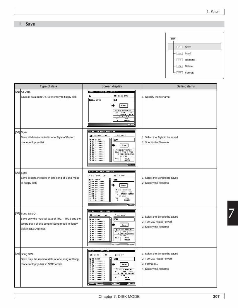
307Chapter 7. DISK MODE
7
1. Save
1. Save
1ÊSave
2ÊLoad
4ÊRename
5ÊDelete
6ÊFormat
d
Type of data Screen display Setting items
1. Specify the filename
1. Select the Style to be saved
2. Specify the filename
1. Select the Song to be saved
2. Specify the filename
1. Select the Song to be saved
2. Turn XG Header on/off
3. Specify the filename
1. Select the Song to be saved
2. Turn XG Header on/off
3. Format 0/1
4. Specify the filename
[D1]
[D2]
[D3]
[D4]
[D5]
All Data
Save all data from QY700 memory to floppy disk.
Style
Save all data included in one Style of Pattern
mode to floppy disk.
Song
Save all data included in one song of Song mode
to floppy disk.
Song ESEQ
Save only the musical data of TR1 – TR16 and the
tempo track of one song of Song mode to floppy
disk in ESEQ format.
Song SMF
Save only the musical data of one song of Song
mode to floppy disk in SMF format.
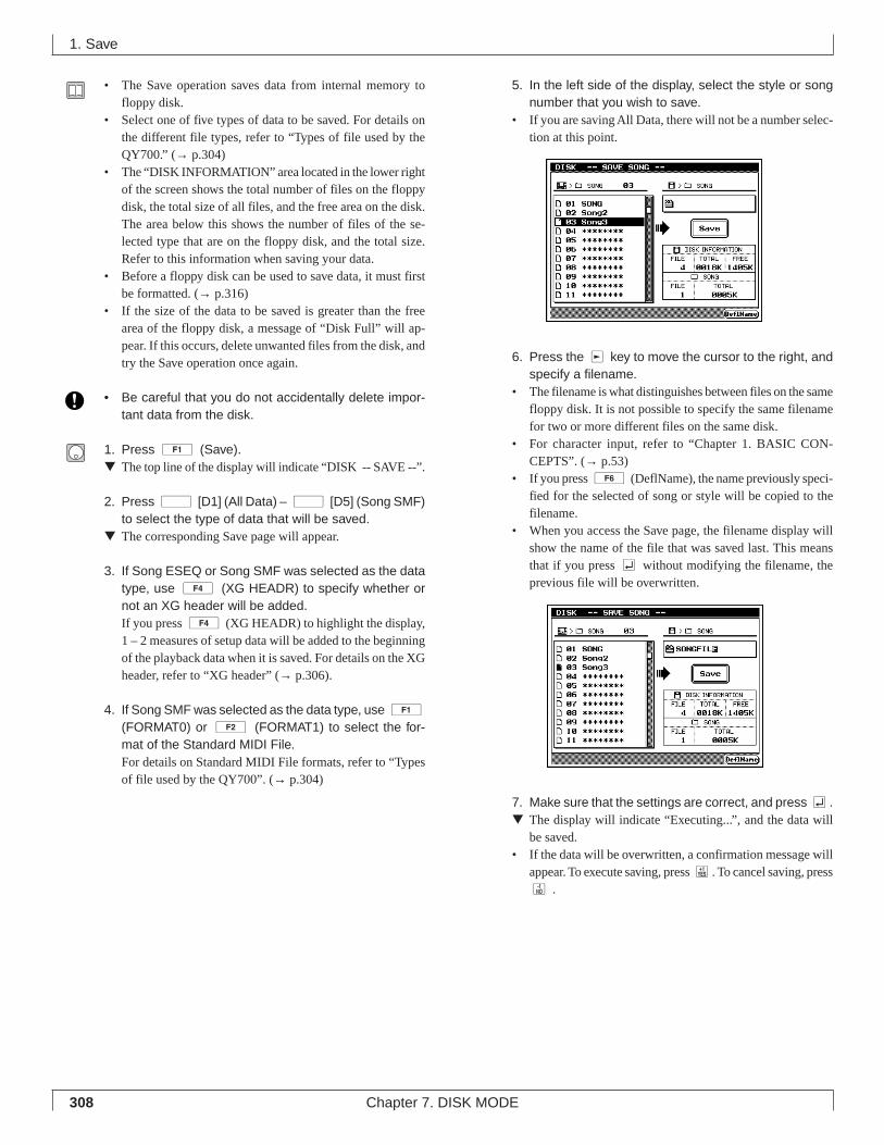
308 Chapter 7. DISK MODE
• The Save operation saves data from internal memory tofloppy disk.
• Select one of five types of data to be saved. For details onthe different file types, refer to “Types of file used by theQY700.” (→ p.304)
• The “DISK INFORMATION” area located in the lower rightof the screen shows the total number of files on the floppydisk, the total size of all files, and the free area on the disk.The area below this shows the number of files of the se-lected type that are on the floppy disk, and the total size.Refer to this information when saving your data.
• Before a floppy disk can be used to save data, it must firstbe formatted. (→ p.316)
• If the size of the data to be saved is greater than the freearea of the floppy disk, a message of “Disk Full” will ap-pear. If this occurs, delete unwanted files from the disk, andtry the Save operation once again.
• Be careful that you do not accidentally delete impor-tant data from the disk.
1. Press 1 (Save).▼ The top line of the display will indicate “DISK -- SAVE --”.
2. Press d [D1] (All Data) – d [D5] (Song SMF)to select the type of data that will be saved.
▼ The corresponding Save page will appear.
3. If Song ESEQ or Song SMF was selected as the datatype, use 4 (XG HEADR) to specify whether ornot an XG header will be added.If you press 4 (XG HEADR) to highlight the display,1 – 2 measures of setup data will be added to the beginningof the playback data when it is saved. For details on the XGheader, refer to “XG header” (→ p.306).
4. If Song SMF was selected as the data type, use 1(FORMAT0) or 2 (FORMAT1) to select the for-mat of the Standard MIDI File.For details on Standard MIDI File formats, refer to “Typesof file used by the QY700”. (→ p.304)
5. In the left side of the display, select the style or songnumber that you wish to save.
• If you are saving All Data, there will not be a number selec-tion at this point.
6. Press the r key to move the cursor to the right, andspecify a filename.
• The filename is what distinguishes between files on the samefloppy disk. It is not possible to specify the same filenamefor two or more different files on the same disk.
• For character input, refer to “Chapter 1. BASIC CON-CEPTS”. (→ p.53)
• If you press 6 (DeflName), the name previously speci-fied for the selected of song or style will be copied to thefilename.
• When you access the Save page, the filename display willshow the name of the file that was saved last. This meansthat if you press e without modifying the filename, theprevious file will be overwritten.
7. Make sure that the settings are correct, and press e.▼ The display will indicate “Executing...”, and the data will
be saved.• If the data will be overwritten, a confirmation message will
appear. To execute saving, press y. To cancel saving, pressn .
1. Save
309Chapter 7. DISK MODE
7
8. Press e to close the Save page.• When saving a style or song, memory numbers for which
there is no data will be displayed as “********” If you at-tempt to save such styles or songs, a message of “No Data”will appear, and it will not be possible to execute the Saveoperation.
• It is not possible to use “*” or “?” characters in a filename.• If a filename includes characters such as spaces or periods
which are not permitted by MS-DOS, computers or otherdevices may not be able to read that file. (MS-DOS is aregistered trademark of Microsoft Corporation.)
1. Save
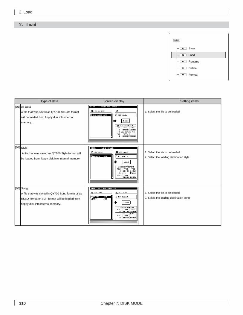
310 Chapter 7. DISK MODE
2. Load
2. Load
1ÊSave
2ÊLoad
4ÊRename
5ÊDelete
6ÊFormat
d
Type of data Screen display Setting items
1. Select the file to be loaded
1. Select the file to be loaded
2. Select the loading destination style
1. Select the file to be loaded
2. Select the loading destination song
[D1]
[D2]
[D3]
All Data
A file that was saved as QY700 All Data format
will be loaded from floppy disk into internal
memory.
Style
A file that was saved as QY700 Style format will
be loaded from floppy disk into internal memory.
Song
A file that was saved in QY700 Song format or as
ESEQ format or SMF format will be loaded from
floppy disk into internal memory.
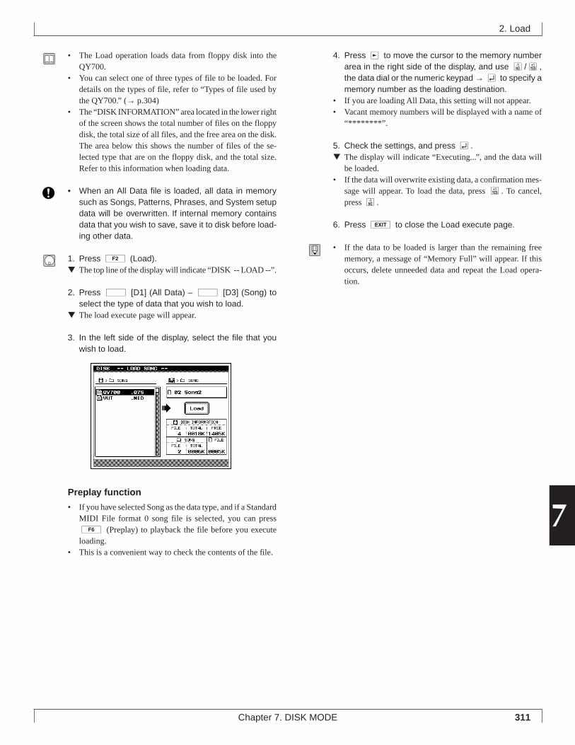
311Chapter 7. DISK MODE
7
• The Load operation loads data from floppy disk into theQY700.
• You can select one of three types of file to be loaded. Fordetails on the types of file, refer to “Types of file used bythe QY700.” (→ p.304)
• The “DISK INFORMATION” area located in the lower rightof the screen shows the total number of files on the floppydisk, the total size of all files, and the free area on the disk.The area below this shows the number of files of the se-lected type that are on the floppy disk, and the total size.Refer to this information when loading data.
• When an All Data file is loaded, all data in memorysuch as Songs, Patterns, Phrases, and System setupdata will be overwritten. If internal memory containsdata that you wish to save, save it to disk before load-ing other data.
1. Press 2 (Load).▼ The top line of the display will indicate “DISK -- LOAD --”.
2. Press d [D1] (All Data) – d [D3] (Song) toselect the type of data that you wish to load.
▼ The load execute page will appear.
3. In the left side of the display, select the file that youwish to load.
Preplay function
• If you have selected Song as the data type, and if a StandardMIDI File format 0 song file is selected, you can press6 (Preplay) to playback the file before you executeloading.
• This is a convenient way to check the contents of the file.
4. Press r to move the cursor to the memory numberarea in the right side of the display, and use n/y,the data dial or the numeric keypad → e to specify amemory number as the loading destination.
• If you are loading All Data, this setting will not appear.• Vacant memory numbers will be displayed with a name of
“********”.
5. Check the settings, and press e.▼ The display will indicate “Executing...”, and the data will
be loaded.• If the data will overwrite existing data, a confirmation mes-
sage will appear. To load the data, press y. To cancel,press n.
6. Press e to close the Load execute page.
• If the data to be loaded is larger than the remaining freememory, a message of “Memory Full” will appear. If thisoccurs, delete unneeded data and repeat the Load opera-tion.
2. Load
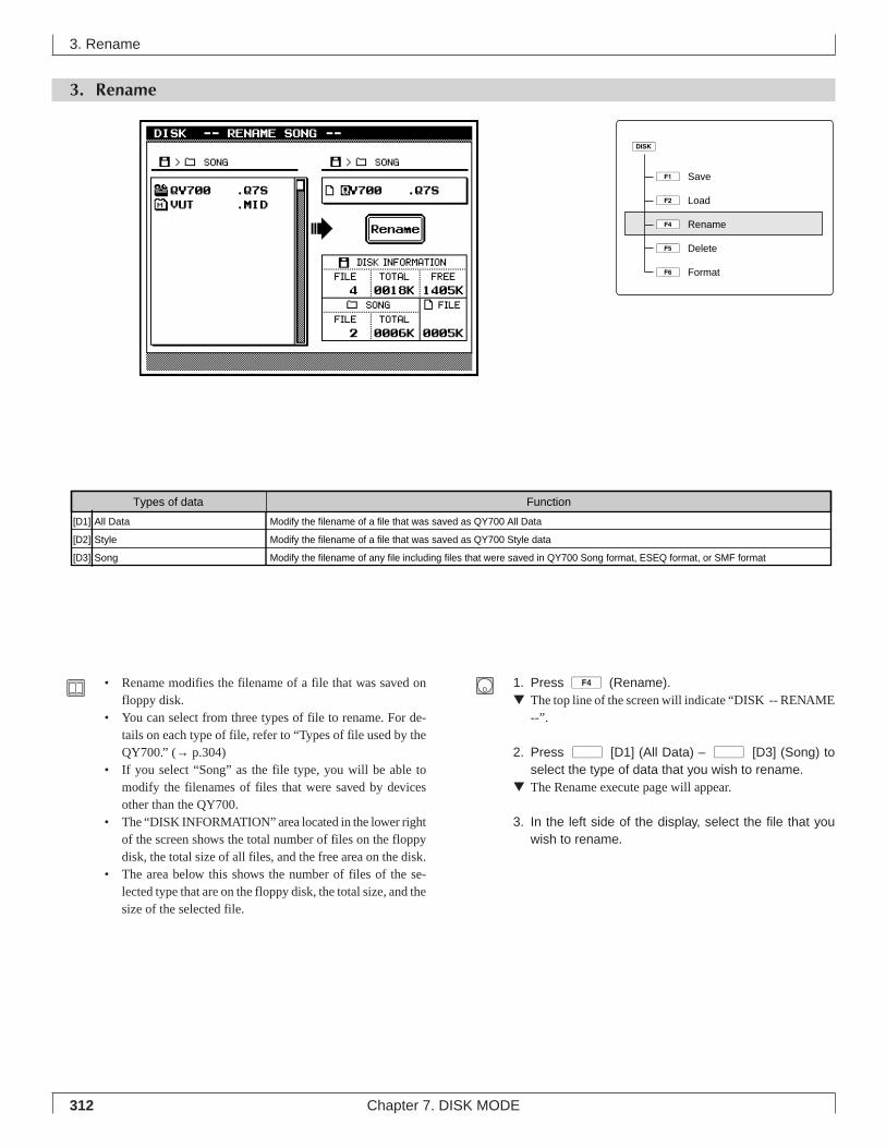
312 Chapter 7. DISK MODE
3. Rename
3. Rename
• Rename modifies the filename of a file that was saved onfloppy disk.
• You can select from three types of file to rename. For de-tails on each type of file, refer to “Types of file used by theQY700.” (→ p.304)
• If you select “Song” as the file type, you will be able tomodify the filenames of files that were saved by devicesother than the QY700.
• The “DISK INFORMATION” area located in the lower rightof the screen shows the total number of files on the floppydisk, the total size of all files, and the free area on the disk.
• The area below this shows the number of files of the se-lected type that are on the floppy disk, the total size, and thesize of the selected file.
1. Press 4 (Rename).▼ The top line of the screen will indicate “DISK -- RENAME
--”.
2. Press d [D1] (All Data) – d [D3] (Song) toselect the type of data that you wish to rename.
▼ The Rename execute page will appear.
3. In the left side of the display, select the file that youwish to rename.
1ÊSave
2ÊLoad
4ÊRename
5ÊDelete
6ÊFormat
d
Modify the filename of a file that was saved as QY700 All Data
Modify the filename of a file that was saved as QY700 Style data
Modify the filename of any file including files that were saved in QY700 Song format, ESEQ format, or SMF format
[D1]
[D2]
[D3]
All Data
Style
Song
FunctionTypes of data
313Chapter 7. DISK MODE
7
3. Rename
4. Press r to move the cursor to the right, and modifythe filename.
• For details on inputting characters, refer to “Chapter 1. BA-SIC CONCEPTS”. (→ p.53)
5. Check the settings, and press e.▼ The display will indicate “Executing...” and the filename
will be changed.• If you press e without modifying the filename, the dis-
play will indicate “Can’t Change File Name,” and the Re-name operation cannot be executed.
6. Press e to close the Rename execute page.
• If the filename extension of an ESEQ/SMF file is renamed,it may become impossible to load the file.
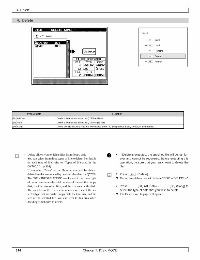
314 Chapter 7. DISK MODE
4. Delete
• Delete allows you to delete files from floppy disk.• You can select from three types of file to delete. For details
on each type of file, refer to “Types of file used by theQY700.” (→ p.304)
• If you select “Song” as the file type, you will be able todelete files that were saved by devices other than the QY700.
• The “DISK INFORMATION” area located in the lower rightof the screen shows the total number of files on the floppydisk, the total size of all files, and the free area on the disk.The area below this shows the number of files of the se-lected type that are on the floppy disk, the total size, and thesize of the selected file. You can refer to this area whendeciding which files to delete.
• If Delete is executed, the specified file will be lost for-ever and cannot be recovered. Before executing thisoperation, be sure that you really want to delete thefile.
1. Press 5 (Delete).▼ The top line of the screen will indicate “DISK -- DELETE --”.
2. Press d [D1] (All Data) – d [D3] (Song) toselect the type of data that you wish to delete.
▼ The Delete execute page will appear.
4. Delete
1ÊSave
2ÊLoad
4ÊRename
5ÊDelete
6ÊFormat
d
Type of data Function
Delete a file that was saved as QY700 All Data
Delete a file that was saved as QY700 Style data
Delete any file including files that were saved in QY700 Song format, ESEQ format, or SMF format
[D1]
[D2]
[D3]
All Data
Style
Song
315Chapter 7. DISK MODE
7
4. Delete
3. Use u/d to select the file that you wish to delete.
4. Check the display, and press e.▼ A message will ask for confirmation.
5. Pressy.▼ The display will indicate “Executing...” and the file will be
deleted.• To cancel without deleting, press n.
6. Press e to close the Delete execute page.
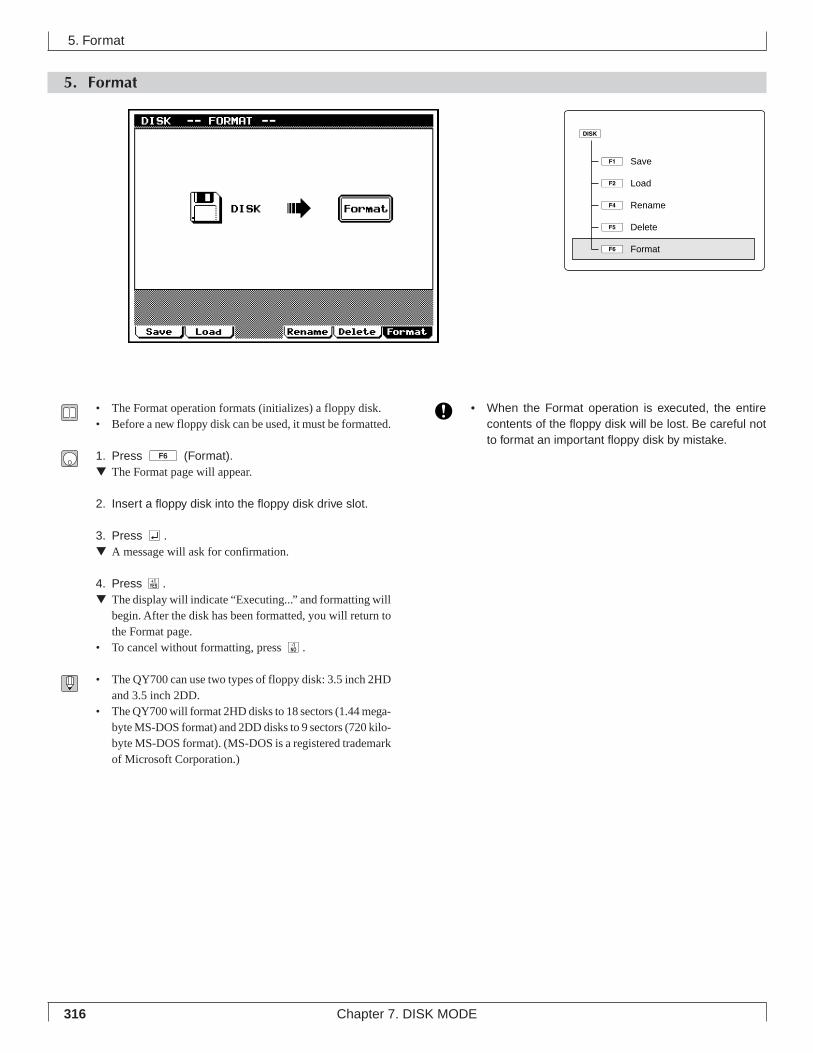
316 Chapter 7. DISK MODE
5. Format
5. Format
• The Format operation formats (initializes) a floppy disk.• Before a new floppy disk can be used, it must be formatted.
1. Press 6 (Format).▼ The Format page will appear.
2. Insert a floppy disk into the floppy disk drive slot.
3. Press e.▼ A message will ask for confirmation.
4. Press y.▼ The display will indicate “Executing...” and formatting will
begin. After the disk has been formatted, you will return tothe Format page.
• To cancel without formatting, press n.
• The QY700 can use two types of floppy disk: 3.5 inch 2HDand 3.5 inch 2DD.
• The QY700 will format 2HD disks to 18 sectors (1.44 mega-byte MS-DOS format) and 2DD disks to 9 sectors (720 kilo-byte MS-DOS format). (MS-DOS is a registered trademarkof Microsoft Corporation.)
• When the Format operation is executed, the entirecontents of the floppy disk will be lost. Be careful notto format an important floppy disk by mistake.
1ÊSave
2ÊLoad
4ÊRename
5ÊDelete
6ÊFormat
d
APPENDIX
1. Specifications ........................................... 3182. Troubleshooting ........................................ 3203. Error messages ........................................ 3224. Glossary ................................................... 3245. Index ........................................................ 328
APP
END
IXIN
DEX
318 APPENDIX
1. Specifications
Sequencer block
Data capacity approximately 110,000 notesNote resolution 480 clocks per quarter notePolyphony 64 notesTempo 25.0 – 300.0Record modes Realtime Recording, Punch Recording, Step RecordingTracks Song: 35 tracks (TR1 – TR32, Pattern, Chord, Tempo)
Pattern: 16 tracks (TR1 – TR16)Songs 20 songsPatterns 64 user styles x 8 sections (512 user styles)Phrases 3,876 preset phrases
up to 99 user phrases for each styleChord Presets 12 × 28 types (including Thru)Edit Voice edit
Drum Setup editSong editPhrase edit
Jobs Song jobs: 25Pattern jobs: 30
Play effects Groove Quantize, Clock Shift / Gate Time / Velocity, TransposeFingered Chord functions Chord Root, Chord Type, On Bass, Original BassSequence file formats QY700 native sequence format, ESEQ, SMF formats 0/1
Tone generator block
Type AWM2 tone generatorMaximum polyphony 32 notesMulti-timbral capability 32 timbres (with DVA)Preset voices Normal voices 480
Drum voices 11Effects 3 systems (Reverb effect, Chorus effect, Variation effect)
Reverb 11 typesChorus 11 typesVariation 43 types
ControlsPower switch (POWER ON/OFF)Volume control (VOLUME)Pitch wheelAssignable wheelShuttle dialData dialMode keys (s, p, u, v, e, d)Sub-mode keys (e, j)Function keys (1 –6)Direct keys (d D1 – d D5)SHIFT × 2, EXIT × 1CONTRAST control
1. Specifications
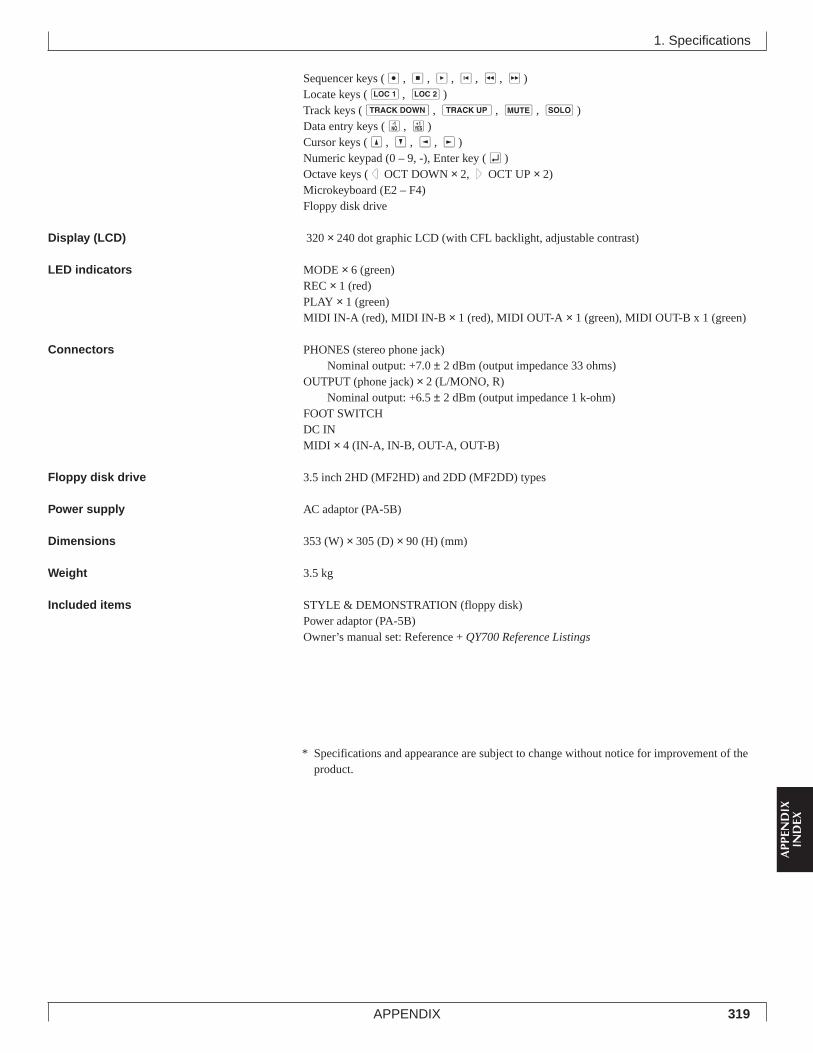
319APPENDIX
APP
END
IXIN
DEX
Sequencer keys (e, s, p, t, r, f)Locate keys (1, 2)Track keys (d, u, m, s)Data entry keys (n, y)Cursor keys (u, d, l, r)Numeric keypad (0 – 9, -), Enter key (e)Octave keys (d OCT DOWN × 2, u OCT UP × 2)Microkeyboard (E2 – F4)Floppy disk drive
Display (LCD) 320 × 240 dot graphic LCD (with CFL backlight, adjustable contrast)
LED indicators MODE × 6 (green)REC × 1 (red)PLAY × 1 (green)MIDI IN-A (red), MIDI IN-B × 1 (red), MIDI OUT-A × 1 (green), MIDI OUT-B x 1 (green)
Connectors PHONES (stereo phone jack)Nominal output: +7.0 ± 2 dBm (output impedance 33 ohms)
OUTPUT (phone jack) × 2 (L/MONO, R)Nominal output: +6.5 ± 2 dBm (output impedance 1 k-ohm)
FOOT SWITCHDC INMIDI × 4 (IN-A, IN-B, OUT-A, OUT-B)
Floppy disk drive 3.5 inch 2HD (MF2HD) and 2DD (MF2DD) types
Power supply AC adaptor (PA-5B)
Dimensions 353 (W) × 305 (D) × 90 (H) (mm)
Weight 3.5 kg
Included items STYLE & DEMONSTRATION (floppy disk)Power adaptor (PA-5B)Owner’s manual set: Reference + QY700 Reference Listings
1. Specifications
* Specifications and appearance are subject to change without notice for improvement of theproduct.
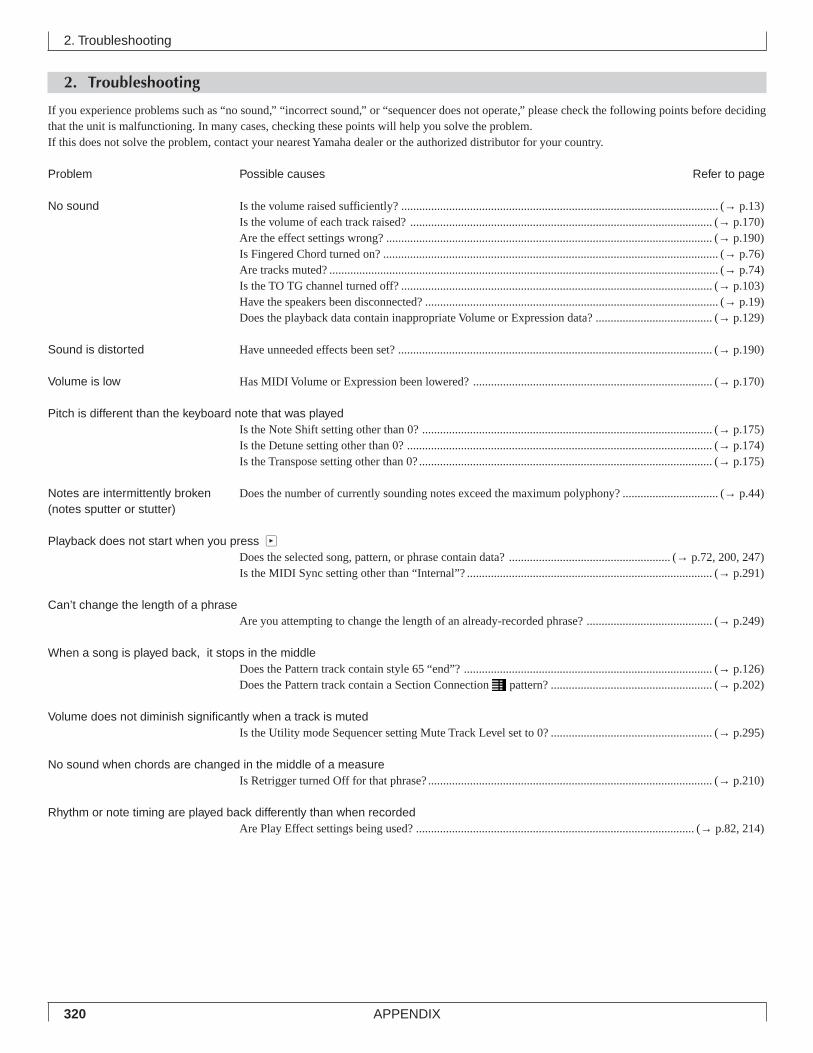
320 APPENDIX
2. Troubleshooting
2. Troubleshooting
If you experience problems such as “no sound,” “incorrect sound,” or “sequencer does not operate,” please check the following points before decidingthat the unit is malfunctioning. In many cases, checking these points will help you solve the problem.If this does not solve the problem, contact your nearest Yamaha dealer or the authorized distributor for your country.
Problem Possible causes Refer to page
No sound Is the volume raised sufficiently? .......................................................................................................... (→ p.13)Is the volume of each track raised? ..................................................................................................... (→ p.170)Are the effect settings wrong? ............................................................................................................. (→ p.190)Is Fingered Chord turned on? ................................................................................................................ (→ p.76)Are tracks muted? .................................................................................................................................. (→ p.74)Is the TO TG channel turned off? ........................................................................................................ (→ p.103)Have the speakers been disconnected? .................................................................................................. (→ p.19)Does the playback data contain inappropriate Volume or Expression data? ....................................... (→ p.129)
Sound is distorted Have unneeded effects been set? ......................................................................................................... (→ p.190)
Volume is low Has MIDI Volume or Expression been lowered? ................................................................................ (→ p.170)
Pitch is different than the keyboard note that was playedIs the Note Shift setting other than 0? ................................................................................................. (→ p.175)Is the Detune setting other than 0? ...................................................................................................... (→ p.174)Is the Transpose setting other than 0?.................................................................................................. (→ p.175)
Notes are intermittently broken Does the number of currently sounding notes exceed the maximum polyphony? ................................ (→ p.44)(notes sputter or stutter)
Playback does not start when you press pDoes the selected song, pattern, or phrase contain data? ...................................................... (→ p.72, 200, 247)Is the MIDI Sync setting other than “Internal”? .................................................................................. (→ p.291)
Can’t change the length of a phraseAre you attempting to change the length of an already-recorded phrase? .......................................... (→ p.249)
When a song is played back, it stops in the middleDoes the Pattern track contain style 65 “end”? ................................................................................... (→ p.126)Does the Pattern track contain a Section Connection pattern? ...................................................... (→ p.202)
Volume does not diminish significantly when a track is mutedIs the Utility mode Sequencer setting Mute Track Level set to 0? ...................................................... (→ p.295)
No sound when chords are changed in the middle of a measureIs Retrigger turned Off for that phrase?............................................................................................... (→ p.210)
Rhythm or note timing are played back differently than when recordedAre Play Effect settings being used? ............................................................................................. (→ p.82, 214)
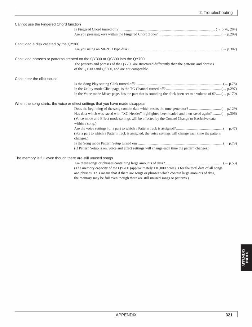
321APPENDIX
APP
END
IXIN
DEX
2. Troubleshooting
Cannot use the Fingered Chord functionIs Fingered Chord turned off? ....................................................................................................... (→ p.76, 204)Are you pressing keys within the Fingered Chord Zone? ................................................................... (→ p.299)
Can’t load a disk created by the QY300Are you using an MF2DD type disk? .................................................................................................. (→ p.302)
Can’t load phrases or patterns created on the QY300 or QS300 into the QY700The patterns and phrases of the QY700 are structured differently than the patterns and phrasesof the QY300 and QS300, and are not compatible.
Can’t hear the click soundIs the Song Play setting Click turned off? ............................................................................................. (→ p.78)In the Utility mode Click page, is the TG Channel turned off? ........................................................... (→ p.297)In the Voice mode Mixer page, has the part that is sounding the click been set to a volume of 0?..... (→ p.170)
When the song starts, the voice or effect settings that you have made disappearDoes the beginning of the song contain data which resets the tone generator? .................................. (→ p.129)Has data which was saved with “XG Header” highlighted been loaded and then saved again? ......... (→ p.306)(Voice mode and Effect mode settings will be affected by the Control Change or Exclusive datawithin a song.)Are the voice settings for a part to which a Pattern track is assigned? .................................................. (→ p.47)(For a part to which a Pattern track is assigned, the voice settings will change each time the patternchanges.)Is the Song mode Pattern Setup turned on? ........................................................................................... (→ p.73)(If Pattern Setup is on, voice and effect settings will change each time the pattern changes.)
The memory is full even though there are still unused songsAre there songs or phrases containing large amounts of data?.............................................................. (→ p.53)(The memory capacity of the QY700 (approximately 110,000 notes) is for the total data of all songsand phrases. This means that if there are songs or phrases which contain large amounts of data,the memory may be full even though there are still unused songs or patterns.)
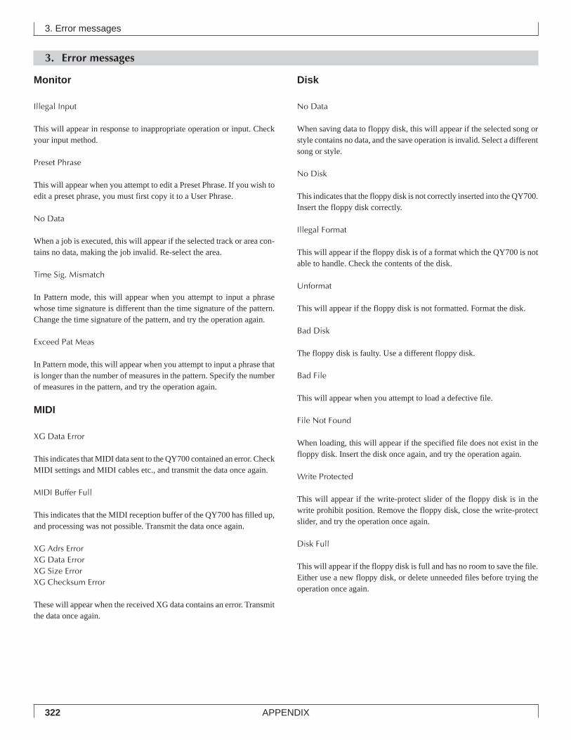
322 APPENDIX
3. Error messages
3. Error messages
Monitor
Illegal Input
This will appear in response to inappropriate operation or input. Checkyour input method.
Preset Phrase
This will appear when you attempt to edit a Preset Phrase. If you wish toedit a preset phrase, you must first copy it to a User Phrase.
No Data
When a job is executed, this will appear if the selected track or area con-tains no data, making the job invalid. Re-select the area.
Time Sig. Mismatch
In Pattern mode, this will appear when you attempt to input a phrasewhose time signature is different than the time signature of the pattern.Change the time signature of the pattern, and try the operation again.
Exceed Pat Meas
In Pattern mode, this will appear when you attempt to input a phrase thatis longer than the number of measures in the pattern. Specify the numberof measures in the pattern, and try the operation again.
MIDI
XG Data Error
This indicates that MIDI data sent to the QY700 contained an error. CheckMIDI settings and MIDI cables etc., and transmit the data once again.
MIDI Buffer Full
This indicates that the MIDI reception buffer of the QY700 has filled up,and processing was not possible. Transmit the data once again.
XG Adrs ErrorXG Data ErrorXG Size ErrorXG Checksum Error
These will appear when the received XG data contains an error. Transmitthe data once again.
Disk
No Data
When saving data to floppy disk, this will appear if the selected song orstyle contains no data, and the save operation is invalid. Select a differentsong or style.
No Disk
This indicates that the floppy disk is not correctly inserted into the QY700.Insert the floppy disk correctly.
Illegal Format
This will appear if the floppy disk is of a format which the QY700 is notable to handle. Check the contents of the disk.
Unformat
This will appear if the floppy disk is not formatted. Format the disk.
Bad Disk
The floppy disk is faulty. Use a different floppy disk.
Bad File
This will appear when you attempt to load a defective file.
File Not Found
When loading, this will appear if the specified file does not exist in thefloppy disk. Insert the disk once again, and try the operation again.
Write Protected
This will appear if the write-protect slider of the floppy disk is in thewrite prohibit position. Remove the floppy disk, close the write-protectslider, and try the operation once again.
Disk Full
This will appear if the floppy disk is full and has no room to save the file.Either use a new floppy disk, or delete unneeded files before trying theoperation once again.
323APPENDIX
APP
END
IXIN
DEX
3. Error messages
Disk Changed
This will appear if you have exchanged disks when you should not have.Try the operation once again from the beginning.
Illegal File
When loading, this will appear if the specified file cannot be handled bythe QY700. Check the contents of the file.
Can’t Change File Name
When renaming, this will appear if the floppy disk already contains a filewith a name identical to the specified filename. Specify a differentfilename.
System
Memory Full
This will appear when internal memory is full and it is not possible torecord, edit, execute a job, receive MIDI, or load from floppy disk. De-lete unneeded songs, patterns, or user phrases, and try the operation onceagain.
Battery Low
This will appear when the internal backup battery of the QY700 has rundown. Contact nearest Yamaha dealer or the authorized distributer foryour country to have the battery replaced.
Messages other than error messages
Can’t Undo. Ok? (Y/N)
If executing a job would fill up the internal memory so that Undo will notbe available, this message will appear. If you are sure that you will notneed to Undo this job, press y. To cancel without executing the job,press n, and delete unneeded songs, patterns, or user phrases beforetrying the operation once again.
Executing...
When loading, saving, or formatting, this message will appear while thejob is being executed. Please wait.
Completed
This will appear when the current process has been completed. Press anykey and the message will disappear.
Are you sure? (Y/N)
Before an operation is executed, this message will ask you for confirma-tion. Use n/y to either cancel or execute.
324 APPENDIX
Clock: A unit of timing resolution. On the QY700, one clock is a lengthof 1/480th of a quarter note.
Control change: A group of MIDI messages that are output when acontroller (modulation wheel, foot controller etc.) is operated.Each controller has its own control number.
Cutoff frequency: Filters work by allowing the portion of the signallower than a given frequency to pass, and cutting the portion ofthe signal above that frequency. This frequency is referred to asthe cutoff frequency.
D
Decay time: The time from when the maximum volume of a note isreached until it falls to the sustain level.
Delay: An effect (or device) that delays an audio signal. The QY700’sVariation effect allows a delay to be applied.
Depth: The amount or degree of a setting or effect.
Dry sound: The audio signal that is not processed by an effect. Normallywhen using an effect, not all of the audio signal is passed throughthe effect. Rather, the degree of the effect is adjusted by mixingthe sound that passes through the effect (the wet sound) with thesound that bypasses the effect (the dry sound).
Dump out: The process of transmitting bulk data as MIDI System Ex-clusive messages.
E
Echo back: The action or process in which data received at the MIDI INconnector is re-transmitted from the MIDI OUT connector.
Edit: The action of modifying or editing data.
Effect: A block (device) that processes the sound to add various effects.The QY700 provides two system effects (reverb and chorus),and one effect (variation) which can be used either as a systemeffect or as insertion effect.
Element: A block within the AWM2 tone generator that generates a sound.The voices of the QY700 consist of 1 to 2 elements.
Envelope Generator (EG): A block that modifies the level of the tonegenerator from the moment that a note is played until the sounddecays to silence. The AEG controls the volume, the PEG con-trols the pitch, and the FEG controls the filter.
ESEQ: A sequence data file format developed by Yamaha. ESEQ-com-patible products can exchange sequence data via floppy disk.(Disks commercially available for Clavinovas and piano playersare exceptions.)
Event: A single piece (such as Note On/Off or Program Change mes-sages) of the data which makes up a sequence.
Exclusive: See the entry for System Exclusive.
Expression: A MIDI control change message used to control the vol-ume of a part.
4. Glossary
A
Aftertouch: MIDI messages which are transmitted when additional pres-sure is applied to the keyboard after notes are played.
Attack time: The time over which the volume rises from 0 when a note isplayed until the maximum volume is reached.
AWM2 tone generation: A method of generating sound developed byYamaha which is based on digitally recorded waveforms. Sinceit generates the complex waveform of actual acoustic instruments,it provides extremely realistic sounds. Digital filtering is alsobuilt-in, allowing precise control over the tone. AWM2 is an ac-ronym for Advanced Wave Memory 2.
B
Bank number: A number which selects a variation voice from an XGextension bank, relative to the voice selected by the ProgramNumber from the 128 voices of the XG basic bank (GM systemlevel 1)
Beat: When playing back or recording a song, one “beat” (a rhythmicsubdivision of a measure).
Beat graph: When using step recording on the QY700 to input notes, agraphic display that indicates the input location.
Brilliance: A control or parameter that regulates the brightness of thetone. The cutoff frequency of the QY700’s filters can be control-led to adjust the brilliance.
Bulk data: A type of System Exclusive message which contains a collec-tion of data for the internal settings of a device.
Bus line: A route (line) that carries audio signals from each part or block.The bus lines of the QY700 include “SendVar → Cho,” “SendVar→ Rev” and “SendCho → Rev,” and the stereo bus line that col-lects the stereo output of each block.
Bypass: An alternative to the usual route. When the QY700’s effects areused with a setting of Variation Mode = System, “bypass” refersto the bus line that allows the outputs of the chorus and variationeffects to be re-input into a different effect.
C
Channel: The means by which the receiver receives only those MIDImessages that are sent from the specified transmitter.
Chord conversion table: The section which contains data that specifieshow the 12 types of Chord Root × 28 types of Chord Type willmodify the notes in the scale.
Chord root: An alphabetical letter which indicates the root of a chord.The QY700 lets you specify 12 different chord roots.
Chord track: A track that lets you record and playback Chord Roots andChord Types.
Chord type: A symbolic or numerical indication of how a chord is com-posed. The QY700 allows you to select from 28 chord types.
Chorus: A type of effect that adds richness and depth to the sound, simi-lar to what happens when multiple sound sources are heard si-multaneously.
Click: A metronome that is sounded when playing back or recording on asequencer.
4. Glossary
325APPENDIX
APP
END
IXIN
DEX
F
Filter: A block which modifies the tone by cutting the output of a specificfrequency portion of the sound. The QY700 has low pass filtersfor each element of a voice, allowing the tone to be made moremellow by cutting the higher overtones, or brighter by allowingthem to pass.
Fingered chord: A function that automatically detects chords based onthe combination of notes that are played on the keyboard, andconverts the playback of patterns or phrases to the chords thatare detected.
Floppy disk: A type of data storage media, available in varieties such as2DD and 2HD. In order for a device to be able to write and readdata to/from a floppy disk, the disk must be formatted appropri-ately for that device.
Foot controller: A control device that can be used to control tone, vol-ume or effects etc. during a performance.
Formatting: The action of initializing a floppy disk so that it can be usedby a specific device.
G
Gate time: The length of time that a note actually sounds.
GM: A specification approved by the MIDI Standards Committee, stand-ardizing the basic functionality of a tone generator, and definingthe number of voices and sounds, etc.
H
Hexadecimal: A system of numbering based on 16, in which the digitsincrement in units of n-th powers of 16. The alphabetical charac-ters A – F are used to express the numbers 10 – 15.
I
IBM-PC/AT series: This is a type of personal computer manufacturedand sold by the International Business Machine Corporation.Compatible computers are manufactured and sold by many com-panies.
Insertion (effect): An effect used in Voice mode as a major factor in thecharacter of a sound. In Song mode, an insertion effect will ap-ply only to the specified part (unlike a system effect), meaningthat you can use the insertion effect “aggressively.”
Instrument: One of the individual instruments such as snare or bass drumthat makes up a drum voice. In a drum voice, a different instru-ment is assigned to each note of the keyboard.
Instrument category: A classification of voice by type of instrument orplaying technique.
Interval time: A delay time that is inserted at regular intervals whentransmitting bulk data that was recorded in a sequence track.
L
Length: On the QY700 this indicates the number of measures in theselected phrase.
LFO: An acronym for Low Frequency Oscillator, a block that produces asignal at a low frequency. The signal from the LFO can be usedto modulate pitch, volume or tone to produce effects such asvibrato, tremolo and wah.
Load: The process of reading data from floppy disk into internal memory.
Location: The place within a song at which notes will be input or play-back will be started, indicated as measure, beat, and clock.
Low pass filter: A type of filter which cuts the high frequencies. Thesound can be brightened by raising the cutoff frequency of thefilter, or darkened by lowering it.
LSB: An acronym for Least Significant Byte, referring to the lower byteof data when MIDI control change data is divided into two bytesfor transmission.
M
Master tune: A parameter that adjust the overall tuning of the entiredevice.
Maximum polyphony: The maximum number of notes that can be playedat once. The QY700 can produce 32 simultaneous notes (countedin 1-element units). If MIDI messages are received requestingmore notes than the maximum polyphony allows, currently sound-ing notes will be turned off, and the later-received notes will beplayed.
MDF2: The product name of a MIDI data filter. This device receives datafor the internal settings of a MIDI device in the form of SystemExclusive messages, and stores them to floppy disk.
Measure: A unit of musical duration consisting of several beats.
MIDI: An acronym for Musical Instruments Digital Interface, a standardfor transferring data between musical instruments. Most elec-tronic musical instruments today implement the MIDI specifica-tion and provide MIDI connectors. Such instruments can be con-nected together to create remote performance or automatic per-formance systems.
MIDI data filer: A MIDI device that receives data for the internal set-tings of a MIDI device in the form of System Exclusive mes-sages, and stores them to floppy disk. An example is the YamahaMDF2 MIDI data filer.
Mixer: On the QY700, the display page in which you can make settingssuch as voice, pan, effect and volume etc. for the voice of eachpart, when recording or playing back.
Modulation wheel: A controller that can be used to smoothly modifythe volume, tone or pitch while you perform.
MSB: An acronym for Most Significant Byte, referring to the upper byteof data when MIDI control change data is divided into two bytesfor transmission.
Multi-timbral tone generator: A tone generator that can simultaneouslyproduce more than one type of sound.
Mute: A function that temporarily silences a track or reduces its volume.
N
Note name: The name which specifies the pitch of a note, expressed asa character, a sharp or flat symbol, and a number indicating theoctave.
NRPN: An acronym for Non Registered Parameter Number. These are atype of MIDI control change message, and are used to edit soundsvia MIDI, allowing you to edit filter or EG settings, or adjust thepitch or level for each instrument of a drum voice.
4. Glossary
326 APPENDIX
O
Offset (Relative) editing: A type of editing in which data is added with-out changing the actual setting; the added data is referred to asthe “offset value.”
On bass: A function that lets you specify a root note for the bass inde-pendently of the chord, so that the playback of a phrase whosePhrase Type is Bass will be fixed on that root note.
Original bass: A function that lets you specify the Chord Root and ChordType for the bass, so that only a phrase whose Phrase Type isBass will playback using the bass chord.
Oscillator: A block or device that produces the waveform on which thesound is based, or a frequency that modulates the sound.
Overdub: A method of realtime recording in which new material is re-corded without erasing previously recorded tracks.
P
Pan: The parameter that sets the stereo location of a sound when it isplayed back in stereo. (“Pan” or “panpot” are abbreviations of“panoramic potentiometer.”) The pan parameters found in VoiceEdit, song play Multi, and Effect Edit are linked.
Parameter: A setting or data item which you can modify in the variousmode and sub-mode displays.
Patch: A screen page in Pattern mode that allows you to select and play-back patterns, and to create patterns by assigning phrases to eachtrack of the pattern.
Pattern: An accompaniment pattern consisting of drums, bass and chordbacking, created by connecting phrases end-to-end or by verti-cally stacking up to16 parts.
Pattern track: The track which records and plays back pattern data.
Phrase: A unit of musical accompaniment played by a accompanimentpart; e.g., a rhythm pattern for the rhythm part, a bass line for thebass part, or chord backing for the guitar part. Phrases are thesmallest unit from which the accompaniment of a song is cre-ated.
Piano roll: When using step recording to input notes, a graphic displaythat indicates the pitch and gate time of the notes, with pitchrepresented by the vertical axis, and measures and beats as thehorizontal axis.
Pitch bend: A type of MIDI message that smoothly modifies the pitch.
Pitch wheel: A controller that smoothly changes the pitch. The PITCHwheel of the QY700 can be assigned to control aspects of thesound other than pitch, such as volume or tone.
Portamento: An effect that smoothly changes the pitch from one note toanother note. Higher settings of Portamento Time will produce aslower change, and there will be no effect with a setting of 0.
Preset: A type of memory that is built into a device. The QY700 haspreset memories for voices, phrases, and patterns.
Program change: A MIDI message that selects a voice.
Program number: On the QY700, a number specifying one of the GM-defined sounds.
Punch recording: A method of realtime recording in which the usesspecifies the punch-in and punch-out points, so that recordingtakes place only in that area.
Q
Quantization: A function which “tightens up” the inexact timing of notesor other events that were entered in realtime.
R
Rate: A type of parameter that controls EG or scaling. For example inthe case of an EG on the QY700, two rates can be adjusted.
Realtime recording: A method of recording in which your performanceis recorded just as you play, similar to a conventional multi-trackrecorder. Since the performance is recorded as you play, themusical expression and nuances of your performance will beaccurately recorded.
Release time: The time over which the volume falls from the sustainlevel (beginning at the moment a note is released) until it reachessilence.
Replace: A method of realtime recording or punch recording in whichpreviously recorded data is erased (replaced) as new material isrecorded.
Resonance: A parameter that boosts the level of the signal in the area ofthe cutoff frequency. By emphasizing the overtones in this area,this can produce a distinctive “peaky” tone, making the soundbrighter and harder.
Reverb: An effect that simulates the acoustical reverberance of a roomor space. The sound that reaches our ear usually includes notonly the direct sound, but also sound that was reflected off thewalls or ceiling. Reverb creates these indirect reflections artifi-cially. Although some reflections can be perceived individuallyas distinct echoes, the term “reverb” usually refers only to theindistinct “wash” of reflected sound.
RPN: An acronym for Registered Parameter Number. These MIDI mes-sages are used to set Part settings such as Pitch Bend Sensitivityor Tuning.
S
Save: The process of saving data or songs from internal memory to floppydisk.
Section: A term referring to each of the eight types of patterns that com-prise a style. Patterns are selected by specifying the style and thesection.
Send level: The amount of signal that is sent to a specified bus line forprocessing by an effect. The amount of signal that is returnedfrom the effect is the “return level.”
Sensitivity: The degree to which an aspect of the sound (e.g., volume)responds to a control (e.g., note velocity).
Sequencer: A block (or device) that records, edits, modifies, and playsback a musical performance in the form of MIDI messages.
Sequence tracks: Tracks which record and playback normal MIDI se-quence data.
SMF: See the entry for Standard MIDI File.
Song: A musical composition created by recording performance data onone or more tracks.
4. Glossary4. Glossary
327APPENDIX
APP
END
IXIN
DEX
Standard MIDI File (SMF): SMF is an acronym for Standard MIDIFile; a format that allows easy exchange of song data betweendifferent sequencers. Most of today’s software and hardwaremanufacturers provide software/hardware that can read and writeStandard MIDI Files.
Step recording: The method of recording in which music is input byentering notes once by one, specifying the note length, velocity,and pitch etc. of each note.
Stereo location: The location within the stereo field from which a soundis heard. This can be modified by the Pan setting.
Store: In Voice mode, the process in which a voice created in the editbuffer is saved to internal memory.
Style: The collective name for a set of eight sections (intro, fill-in, end-ing, etc.). Sections are put together to create a backing pattern.
Synchronization: The function or process of matching the playback orrecording tempo of a device with a separate, external device suchas another sequencer or a rhythm machine.
Sync: See Synchronization.
System (effect): An effect which can be applied to all parts by adjustingthe Send Levels and Return Level. System effects allow reverbor chorus etc. to be applied to the overall music. The QY700provides Reverb and Chorus as system effects. The Variation ef-fect can also be used as a system effect.
System exclusive message: A type of MIDI message used to exchangedata unique to a specific model or type of device.
T
Tempo track: The track containing data that determines the playbacktempo of the song.
Track: A location where musical performance data is recorded.
Transpose: Shifting the pitch in semitone steps.
Tremolo: An effect produced by cyclically modulating the volume.
Tuning: The process of matching the pitch of two or more instrumentswhen playing in an ensemble. Normally, A3 is tuned to 440 Hz.
U
Utility mode: A mode on the QY700 in which system or MIDI settingscan be made.
V
Variation effect: One of the QY700’s effects. In Voice mode, this effectcan be used aggressively as a major component of a sound. TheVariation effect can function either as an insertion effect or as asystem effect, and provides a wide variety of effect programssuch as delay, rotary speaker, auto pan, amp simulation and autowah in addition to reverb and chorus.
Velocity: A numerical value indicating the speed (force) with which anote was played.
Vibrato: A performance effect produced by cyclically modifying the pitch.
Voice: A sound that is built into the tone generator that can be selectedand played.
Voice category: On the QY700, a broad classification of voices thatgroups them as Normal voices, Drum voices, SFX voices etc.
Volume: A parameter or control that adjusts the volume. Track Volumeadjusts the volume of each track, and Master Volume adjusts theoverall volume.
W
Wah effect: An effect that cyclically modulates the tone. The QY700produces this effect by using an LFO signal to modulate the cut-off frequency of the filter.
Waves: Digitally recorded waveforms of various instruments, which arethe basis for AWM2 tone generation.
Wet sound: The audio signal that is processed by an effect. Normallywhen using an effect, not all of the audio signal is passed throughthe effect. Rather, the degree of the effect is adjusted by mixingthe sound that passes through the effect (the wet sound) with thesound that bypasses the effect (the dry sound).
X
XG: A tone generator format developed by Yamaha which expands theGM specification to provide the richer expressiveness and up-ward data compatibility that is demanded by today’s more so-phisticated computer peripheral environment.
4. Glossary4. Glossary
328 APPENDIX
5. Index
y key ............................................................................................... 15n key ............................................................................................... 152Band EQ (2 band equalizer) ........................................................... 1922DD .......................................................................................... 302, 3162HD .......................................................................................... 302, 3163Band EQ (3 band equalizer) ........................................................... 192
A
AC1 control .............................................................................. 195, 246ACCENT note .................................................................................. 298All Data ............................................................................................ 304Alternate group ................................................................................. 185AMP SIM ......................................................................................... 192Append Pattern ................................................................................. 282Append Phrase .................................................................................. 275ASSINABLE WHEEL ..................................................................... 290ASSINABLE wheel ............................................................................ 12Auto Pan ........................................................................................... 192AUTO WAH ..................................................................................... 192Auto-accompaniment ....................................................................... 106
B
BACKLITE SAVER ......................................................................... 289Bank number .................................................................................... 173BASEMENT ..................................................................................... 194Beat Graph ................................................................................ 121, 136Beat shift ........................................................................................... 207BEND CNTRL (Pitch bend control) ................................................ 181BkDelete (Back delete) ............................................................. 120, 124
C
Cable clip ............................................................................................ 16CAT (channel aftertouch) ......................................................... 290, 294CC (control change) ......................................................................... 293CELESTE ......................................................................................... 191CHORD .............................................................................. 70, 110, 127Chord root ........................................................................... 75, 128, 203Chord Separate ......................................................................... 152, 266Chord Sort ................................................................................ 151, 265CHORD Track .......................................................................... 115, 127Chord type .......................................................................... 75, 128, 203Chorus....................................................................................... 188, 135Chorus Edit ....................................................................................... 244Chorus pan ........................................................................................ 192Chorus return .................................................................................... 192Chorus send .............................................................................. 173, 184Chorus type ....................................................................................... 191Chorus-to-reverb ............................................................................... 243Clear ........................................................................... 99, 126, 208, 224Clear All ............................................................................................ 133Clear Pattern ..................................................................................... 284Clear Phrase ...................................................................................... 279Clear Song ........................................................................................ 164Clear Track ............................................................................... 162, 280
Click ................................................................................................. 297Click beat .......................................................................................... 205Click mode........................................................................................ 205Clock shift .................................................................................... 88, 91Cnnect (connection) .................................................................. 188, 242Connection ........................................................................................ 190CONTRAST control ........................................................................... 13CONTRL (Control Change) ............................................................. 137Control .............................................................................................. 195Controllable parameter ..................................................................... 245Copy Event ............................................................................... 154, 268Copy Pattern ..................................................................................... 281Copy Phrase ...................................................................................... 272Copy Song ................................................................................ 140, 164Copy Track ............................................................................... 140, 160CopyTmp (Copy template) ................................................................. 89Count ................................................................................................ 205Create Measure ......................................................................... 140, 158Crescendo ................................................................................. 148, 263CROSSDELAY ................................................................................ 192Current measure................................................................................ 204Cursor keys ......................................................................................... 15
D
Data dial .............................................................................................. 13DC IN jack .......................................................................................... 16Decay (EG decay time) .................................................................... 234Default ........................................................................................ 99, 224DELAY ............................................................................................. 192Delete ........................................................................................ 120, 134Delete Measure ......................................................................... 124, 159Detune............................................................................................... 175Direct keys .......................................................................................... 13DISK key ............................................................................................ 12Disk mode ......................................................................................... 301Disk-in-use indicator .......................................................................... 17DISTORTION .................................................................................. 192DrS1Edit ........................................................................................... 183DrS3Edit ........................................................................................... 236DrTabEdit (drum table edit) ....................................................... 98, 223Drum kit ............................................................................................ 184Drum Setup Edit ............................................................................... 182Drum table .................................................................................. 95, 220DRY LEVEL .................................................................................... 181Dry/Wet ............................................................................................ 195
E
ECHO ............................................................................................... 192ECHO BACK ................................................................................... 292EDIT ................................................................................................. 130EDIT key ............................................................................................ 14EFFECT............................................................................................ 191EFFECT key ....................................................................................... 12Effect mode....................................................................................... 187
5. Index
329APPENDIX
APP
END
IXIN
DEX
Effect parameters .............................................................................. 195Effect type......................................................................................... 194EG ATTCK (EG attack time) ................................... 180, 185, 234, 238EG DCAY1/2 (EG decay time 1/2) .................................................. 185EG DECAY (EG decay time) ........................................................... 180EG RLESE (EG release time) .......................................................... 180Eject button ......................................................................................... 17Element reserve ................................................................................ 177ENTER key......................................................................................... 15ER ..................................................................................................... 192Erase Event ............................................................................... 155, 269Error messages.................................................................................. 322Event ................................................................................................. 140EVENT CHASE ............................................................................... 295EvntList ............................................................................................ 135Exc (system exclusive) ..................................................................... 131Expand Backing................................................................................ 162Expression ........................................................................................ 173Extract Event ............................................................................ 155, 269
F
FILTER CUTOFF..................................................................... 179, 185FILTER RESONANCE ............................................................ 179, 185Fingered chord zone ......................................................................... 299FINGRD (Fingered-chord switch) ..................................................... 76Floppy disk slot .................................................................................. 17FngZone (fingered chord zone) ........................................................ 299FOOT SW jack ................................................................................... 16FOOTSWITCH ................................................................................ 290Format ............................................................................................... 316Format 0 ............................................................................................ 305Format 1 ............................................................................................ 305FLANGER........................................................................................ 191From ................................................................................................... 98Front panel .......................................................................................... 12Function keys ...................................................................................... 13Function tree ....................................................................................... 34
G
GATE REV ....................................................................................... 192Gate Time ......................................................................................... 123Gate-time multiplier ..................................................................... 89, 91Get Phrase ......................................................................................... 277Glossary ............................................................................................ 324GM On (GM mode on) ..................................................................... 169Graphic ............................................................................................. 135Groove ........................................................................................ 84, 214Groove gate time ................................................................................ 87Groove quantizing ...................................................................... 82, 214Groove template ................................................................................. 86Groove velocity .................................................................................. 88GrovView (groove view) .................................................................... 84
H
HALL ............................................................................................... 192High key ........................................................................................... 211
I
Icon ....................................................................................................... 6Index ................................................................................................. 328Insert ................................................................................................. 130INTERVAL TIME ............................................................................ 296Inversion Transpose .......................................................................... 220
J
JOB ................................................................................................... 258JOB key .............................................................................................. 14
K
KARAOKE ....................................................................................... 192Key assign......................................................................................... 185Keyboard track ................................................................................... 74
L
LCD display ........................................................................................ 13Level ................................................................................................. 184Load .................................................................................................. 310LOC 1/2 keys ...................................................................................... 14Location ............................................................................ 122, 171, 183Location Pointer ............................................................................... 121Loop Off ............................................................................................. 78Loop On .............................................................................................. 78Low/High limits ................................................................................ 210LSB ..................................................................................................... 44
M
Master Tune ...................................................................................... 289Measure ............................................................................................ 140Meter................................................................................. 102, 111, 204Microkeyboard.................................................................................... 15MIDI ................................................................................................. 291MIDI connectors ................................................................................. 16MIDI CONTROL IN/OUT ............................................................... 292MIDI data monitors ............................................................................ 13MIDI echo back ................................................................................ 292MIDI filter ........................................................................................ 293MIDI OUT-A/B channel setup ......................................................... 105MIDI PORT/CHANNEL .................................................................. 300MIDI sync ......................................................................................... 291Mix Phrase ........................................................................................ 274Mix Track ......................................................................................... 161Mixer ........................................................................................ 171, 227MMC .......................................................................................... 21, 291Mode keys........................................................................................... 12Modify Gate Time .................................................................... 147, 262Modify Velocity ........................................................................ 145, 261MONO/POLY ................................................................................... 177MSB .................................................................................................... 44MTC ........................................................................................... 21, 291MTC start offset ................................................................................ 292MULTI .............................................................................................. 110Multitrack switch .............................................................................. 110
5. Index
330 APPENDIX
MUTE ................................................................................................. 74MUTE key .......................................................................................... 15MUTE mark...................................................................................... 132MUTE TRACKS LEVEL................................................................. 295MW LFO DEPTH A.MOD(Modulation Wheel LFO depthamplitude modulation) ...................................................................... 179MW LFO DEPTH F.MOD(Modulation Wheel LFO depth filtermodulation) ....................................................................................... 179MW LFO DEPTH P.MOD(Modulation Wheel LFO depth pitchmodulation) ....................................................................................... 179
N
Normal .............................................................................................. 151NORMAL note ................................................................................. 298Normalize Play Effect ...................................................................... 163Note .................................................................................................. 293Note name ......................................................................................... 184Note shift .......................................................................................... 175Numeric keypad .................................................................................. 15
O
OCT DOWN key ................................................................................ 15OCT UP key ....................................................................................... 15Octave keys ......................................................................................... 15On-Bass ............................................................................................ 128Open harmony .................................................................................. 221Original Bass .................................................................................... 128OutCh. .............................................................................................. 104Output Channels ............................................................................... 103OUTPUT jacks ................................................................................... 16OVERDRIVE ................................................................................... 192OVERDUB ....................................................................... 110, 112, 252
P
P.BEND (Pitch Bend) ....................................................................... 293P.FX THRU (Play-effects THRU setting) ........................................... 85Pan ............................................................................................ 173, 184Para (Pararell) ................................................................................... 210Part number ...................................................................................... 171PAT (polyphonic aftertouch) ............................................................ 294PATCH .............................................................................................. 200PATT SETUP (Pattern setup) ............................................................. 73Pattern Jobs ...................................................................................... 256Pattern Effects ................................................................................... 239PATTERN key .................................................................................... 12Pattern length ............................................................................ 204, 210Pattern mode ..................................................................................... 197Pattern name ............................................................................. 202, 284Pattern Track ............................................................................. 113, 125PC (program change) ........................................................................ 294PHASER ........................................................................................... 192PHONES jack ..................................................................................... 16Phrase Editing ................................................................................... 254Phrase Name ..................................................................................... 210Phrase number .......................................................................... 207, 210Phrase Recording .............................................................................. 247
Phrase type........................................................................................ 210PhrSolo (phrase solo) ....................................................................... 208PhrTable (phrase table) ..................................................................... 209PITCH BEND WHEEL .................................................................... 290Pitch coarse ....................................................................................... 185Pitch fine ........................................................................................... 184PITCH wheel ...................................................................................... 12PLATE .............................................................................................. 192PLAY indicator ................................................................................... 13PlayFx (Play Effects) .................................................................. 81, 213Point Graph ....................................................................................... 136POWER switch ..................................................................................... 8Program number ............................................................................... 172PORTAMENTO SW (Portamento switch) ....................................... 179PORTAMENTO TIME ..................................................................... 179PUNCH..................................................................................... 110, 118Punch Recording .............................................................................. 118Put Phrase ......................................................................................... 278
Q
Quantize ............................................................................ 140, 142, 260Quantizing value ................................................................................. 86
R
Realtime Recording .......................................................................... 112Realtime Recording .......................................................................... 252Rear panel ........................................................................................... 16REC indicator ..................................................................................... 13Receive note off ................................................................................ 185Recording mode........................................................................ 109, 251Recording Standby ................................................................... 108, 248Recording Track ............................................................................... 110Release (EG release time) ................................................................ 234Rename ............................................................................................. 312REPLACE ........................................................................ 110, 112, 252Replacement List ........................................................................ 98, 223REST ................................................................................................ 208Retrigger ........................................................................................... 210Reverb ....................................................................................... 188, 235Reverb Edit ....................................................................................... 244Reverb pan ........................................................................................ 191Reverb return .................................................................................... 191Reverb Send .............................................................................. 173, 184Reverb type ....................................................................................... 191Reverse ............................................................................................. 151REVRS GATE .................................................................................. 192ROOM .............................................................................................. 192ROTARY SP (rotary speaker) ........................................................... 192
S
Save .................................................................................................. 307Scale time ......................................................................................... 206Section ........................................................................................ 75, 202Section connection............................................................................ 202Send chorus to reberb ....................................................................... 192Send variation to chorus ................................................................... 192
5. Index
331APPENDIX
APP
END
IXIN
DEX
Send variation to reverb .................................................................... 192Sequence Tracks ....................................................................... 112, 120Sequencer ......................................................................................... 295Sequencer keys ................................................................................... 14SetAll ................................................................................................ 133SFX kit .............................................................................................. 172SFX voice ......................................................................................... 172SHF/GT/Vel ........................................................................................ 91Shift Clock ................................................................................ 150, 265Shift Event ................................................................................ 153, 267SHIFT key .......................................................................................... 13Shift Note.................................................................................. 150, 264Shuttle dial .......................................................................................... 13Slur ................................................................................................... 123Solo ..................................................................................................... 74SOLO key ........................................................................................... 15SOLO mark ...................................................................................... 132SONG key........................................................................................... 12Song Editing ..................................................................................... 129Song ESEQ ....................................................................................... 305Song Jobs .......................................................................................... 138SONG key........................................................................................... 12Song mode .......................................................................................... 69Song Name ....................................................................................... 165Song Recording ................................................................................ 106Song SMF ......................................................................................... 305Sostenuto .......................................................................................... 290Source chord ..................................................................................... 211Specifications ................................................................................... 318Split Pattern ...................................................................................... 283Split Phrase ....................................................................................... 276stac (staccato) ................................................................................... 123STAGE .............................................................................................. 192Stereo Recording .............................................................................. 253STEP ......................................................................... 110, 120, 127, 253Step Recording ................................................................................. 120Step Time .......................................................................................... 122Strength............................................................................................... 86Style .................................................................................................. 305Style Icon .......................................................................................... 285Style name ........................................................................................ 202Style number ..................................................................................... 202SYMPHONIC................................................................................... 192Syncopation ...................................................................................... 128System .............................................................................................. 289
T
Table of contents ................................................................................... 9TEMPO....................................................................................... 70, 110TEMPO Track .................................................................................. 117Thin Out .................................................................................... 157, 271THRU ................................................................................................. 85TIE .................................................................................................... 124Time Stretch ............................................................................. 158, 271TO ....................................................................................................... 98TO TG channel setup ........................................................................ 105
Track ................................................................................................... 15TRACK DOWN key ........................................................................... 15Track status ................................................................................. 74, 206TRACK UP key .................................................................................. 15Track View ........................................................................................ 100Transpose ............................................................................ 98, 149, 263Transposition .................................................................. 79, 94, 96, 219TREMOLO ....................................................................................... 192TrNAME (Track name) .................................................................... 132Troubleshooting ................................................................................ 320TrView .............................................................................................. 101Tune .................................................................................................. 175TUNNEL .......................................................................................... 194
U
Undo/Redo ................................................................................ 141, 259US ..................................................................................................... 207UTILITY .......................................................................................... 288UTILITY key ...................................................................................... 12Utility mode ...................................................................................... 287
V
Variation ................................................................................... 188, 235Variation Edit .................................................................................... 244Variation mode.................................................................................. 190Variation pan ..................................................................................... 192Variation return ................................................................................. 192Variation send ........................................................................... 173, 184Variation switch ................................................................................ 173Variation type.................................................................................... 192Variation-to-chorus ........................................................................... 243Variation-to-reverb ............................................................................ 243VELCTY SENS DEPTH (Velocity sensitivity) ............................... 178VELCTY SENS OFFST (Velocity sensitivity offset) ...................... 178VELCTY (Velocity) ......................................................................... 137VELOC (Velocity) ............................................................................ 123Velocity meter ................................................................................... 171Velocity offset ............................................................................... 89, 93Velocity rate ................................................................................ 92, 224VIBRATO DELAY ........................................................................... 180VIBRATO DEPTH ........................................................................... 180VIBRATO RATE .............................................................................. 180View Filet mark ................................................................................ 132ViwFiltr (View Filter) ....................................................................... 133VOICE .............................................................................................. 171Voice category .................................................................................. 171Voice Edit ......................................................................................... 232VOICE key ......................................................................................... 12Voice mode ....................................................................................... 167Voice program ............................................................................ 85, 105VoicEdit (Voice edit) ................................................................ 177, 232Volume .............................................................................................. 173VOLUME control ............................................................................... 13
5. Index
332 APPENDIX
W
WHITE ROOM ................................................................................ 194
X
XG ........................................................................................................ 5XG header ......................................................................................... 306XG On (XG system on) .................................................................... 169XG parameter out ............................................................................. 292XG View ........................................................................................... 132XG Viewer mark ............................................................................... 132
Z
ZONE LOW/HIGH .......................................................................... 299
5. Index
![Sequencer 1, Sequencer 2 or Drum - Arturiadownloads.arturia.com/products/beatstep-pro/manual/BeatStepPro... · —Sequencer 1, Sequencer 2 or Drum SHIFT + [>>] = Extend sequence SHIFT](https://img.pdfslide.us/doc/110x75/5adbc3047f8b9add658e5b6e/sequencer-1-sequencer-2-or-drum-sequencer-1-sequencer-2-or-drum-shift-.jpg)