Embed Size (px)
Citation preview
Qwiic MUX Hookup Guide
Introduction
PCA9548A and TCA9548A? The SparkX version of the Qwiic Mux breakout used the PCA9548A. TheSparkFun red version uses the TCA9548A. Overall, both should be functionally the same with a few minordifferences.
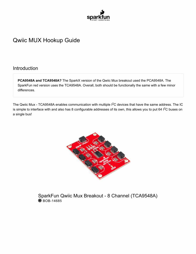
The Qwiic Mux - TCA9548A enables communication with multiple I C devices that have the same address. The ICis simple to interface with and also has 8 configurable addresses of its own, this allows you to put 64 I C buses ona single bus!
2
2
SparkFun Qwiic Mux Breakout - 8 Channel (TCA9548A) BOB-14685
YOUR ACCOUNT
LOG IN
REGISTER
In this tutorial we’ll go over how to talk to sensors on different channels of your MUX. The application of this ispretty straightforward so things won’t get too fancy.
Required Materials
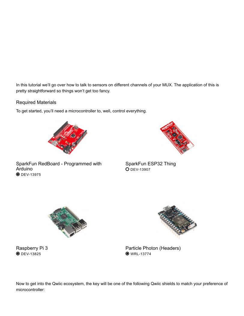
To get started, you’ll need a microcontroller to, well, control everything.
Now to get into the Qwiic ecosystem, the key will be one of the following Qwiic shields to match your preference ofmicrocontroller:
SparkFun RedBoard - Programmed withArduino DEV-13975
SparkFun ESP32 Thing DEV-13907
Raspberry Pi 3 DEV-13825
Particle Photon (Headers) WRL-13774
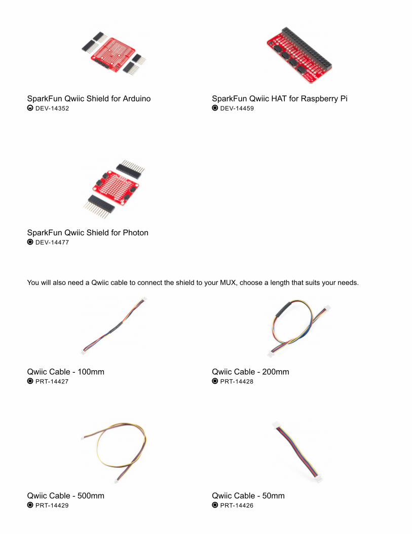
You will also need a Qwiic cable to connect the shield to your MUX, choose a length that suits your needs.
SparkFun Qwiic Shield for Arduino DEV-14352
SparkFun Qwiic HAT for Raspberry Pi DEV-14459
SparkFun Qwiic Shield for Photon DEV-14477
Qwiic Cable - 100mm PRT-14427
Qwiic Cable - 200mm PRT-14428
Qwiic Cable - 500mm PRT-14429
Qwiic Cable - 50mm PRT-14426
Tools
Depending on your setup, you may need a soldering iron, solder, and general soldering accessories.
Suggested Reading
If you aren’t familiar with our new Qwiic system, we recommend reading here for an overview. We would alsorecommend taking a look at the following tutorials if you aren’t familiar with them.
Hardware Overview
What is the difference between the PCA9548A and TCA9548A? Very little. PCA is made by NXP, TCA ismade by TI. PCA can operate from 2.3 to 5.5V, TCA can operate from 1.65 to 5.5V. Everything else isidentical.
Let’s look over a few characteristics of the TCA9548A so we know a bit more about how it behaves.
Solder Lead Free - 100-gram Spool TOL-09325
Weller WLC100 Soldering Station TOL-14228
I2CAn introduction to I2C, one of the main embeddedcommunications protocols in use today.
Qwiic Shield for Arduino & Photon HookupGuideGet started with our Qwiic ecosystem with the Qwiicshield for Arduino or Photon.
Characteristic Range
Operating Voltage 1.65V - 5.5V
Operating Temperature -40 - 85° C
I C Address 0x70 (default) up to 0x77 (see below table)
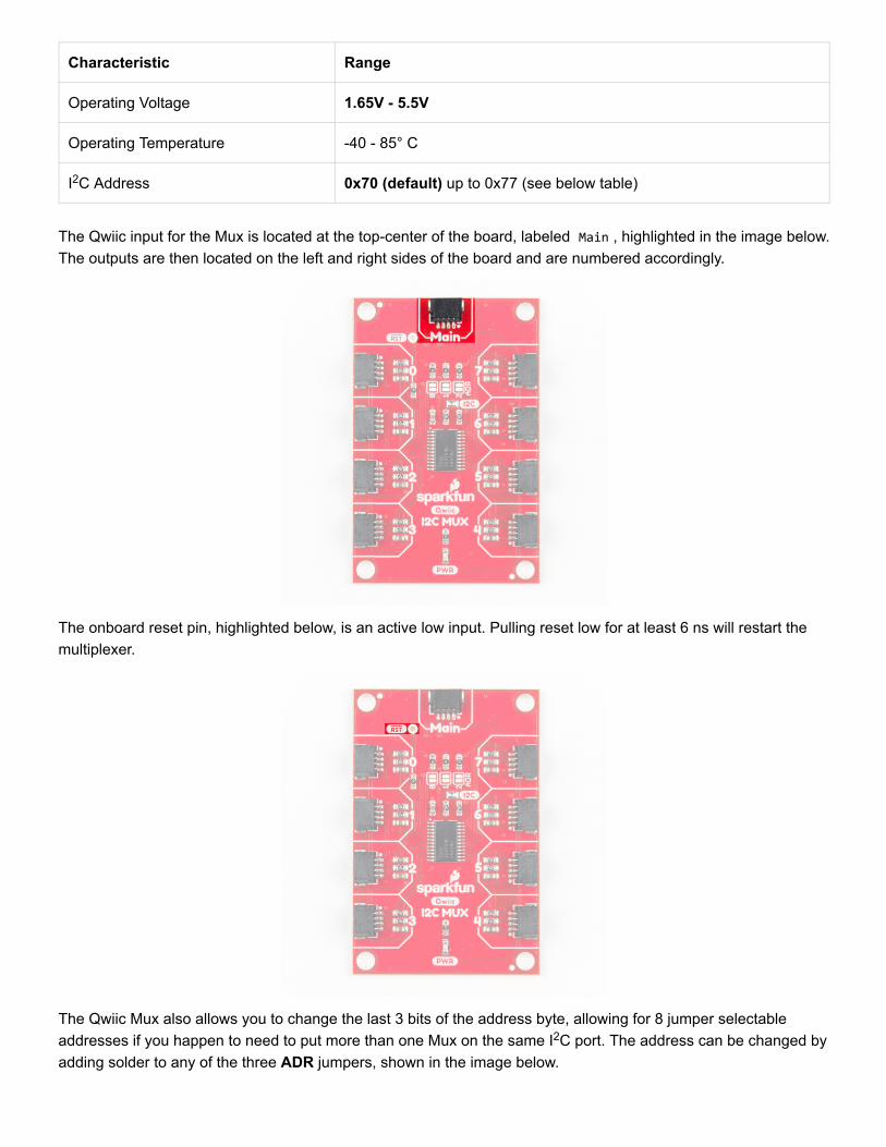
The Qwiic input for the Mux is located at the top-center of the board, labeled Main , highlighted in the image below.The outputs are then located on the left and right sides of the board and are numbered accordingly.
The onboard reset pin, highlighted below, is an active low input. Pulling reset low for at least 6 ns will restart themultiplexer.
The Qwiic Mux also allows you to change the last 3 bits of the address byte, allowing for 8 jumper selectableaddresses if you happen to need to put more than one Mux on the same I C port. The address can be changed byadding solder to any of the three ADR jumpers, shown in the image below.
2
2
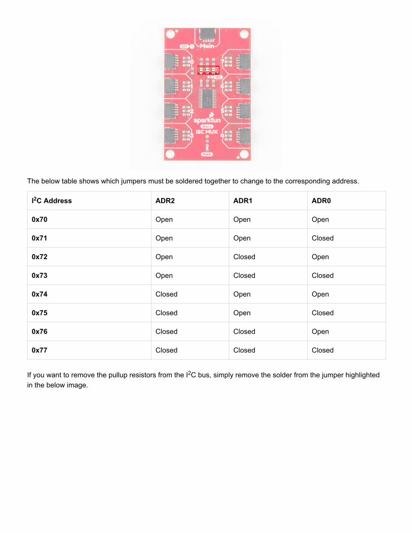
The below table shows which jumpers must be soldered together to change to the corresponding address.
I C Address ADR2 ADR1 ADR0
0x70 Open Open Open
0x71 Open Open Closed
0x72 Open Closed Open
0x73 Open Closed Closed
0x74 Closed Open Open
0x75 Closed Open Closed
0x76 Closed Closed Open
0x77 Closed Closed Closed
If you want to remove the pullup resistors from the I C bus, simply remove the solder from the jumper highlightedin the below image.
2
2
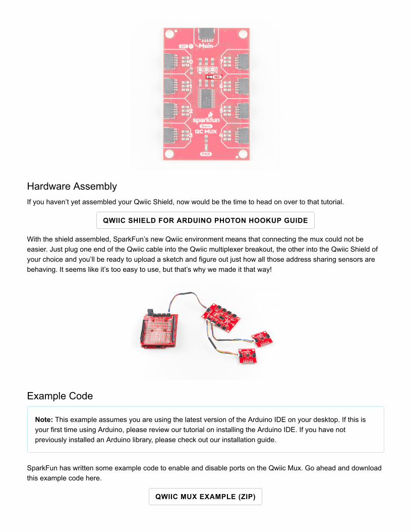
Hardware AssemblyIf you haven’t yet assembled your Qwiic Shield, now would be the time to head on over to that tutorial.
QWIIC SHIELD FOR ARDUINO PHOTON HOOKUP GUIDE
With the shield assembled, SparkFun’s new Qwiic environment means that connecting the mux could not beeasier. Just plug one end of the Qwiic cable into the Qwiic multiplexer breakout, the other into the Qwiic Shield ofyour choice and you’ll be ready to upload a sketch and figure out just how all those address sharing sensors arebehaving. It seems like it’s too easy to use, but that’s why we made it that way!
Example Code
Note: This example assumes you are using the latest version of the Arduino IDE on your desktop. If this isyour first time using Arduino, please review our tutorial on installing the Arduino IDE. If you have notpreviously installed an Arduino library, please check out our installation guide.
SparkFun has written some example code to enable and disable ports on the Qwiic Mux. Go ahead and downloadthis example code here.
QWIIC MUX EXAMPLE (ZIP)
Warning! Make sure to have the Mux_Control.ino in the same folder when compiling the Example1-BasicReadings.ino sketch file. Otherwise, you may have issues uploading code.
Additionally, you will need to install the MMA8452Q Arduino library if you are using two MMA8452Qaccelerometers. First, you’ll need the Sparkfun MMA8452Q Arduino library. You can obtain these libraries throughthe Arduino Library Manager. Search for Sparkfun MMA8452Q Accelerometer by Jim@SparkFun Electronicsto install the latest version. If you prefer downloading the libraries from the GitHub repository and manuallyinstalling it, you can grab them here:
DOWNLOAD SPARKFUN MMA8452Q ACCELEROMETER (ZIP)
Arduino Example Example1-BasicReadings.ino
Opening Example1-BasicReadings will open two tabs in the Arduino IDE, the first example, and alsoMux_Control . Let’s take a look under the hood of Mux_Control to get an idea of what’s going on. There are two
functions here, boolean enableMuxPort(byte portNumber) and boolean disableMuxPort(byte portNumber)which is pretty much all we need to specify which channels we’d like to talk to on the Mux. If we have a sensor onchannel 0, we simply call enableMuxPort(0) to open that channel on the multiplexer. Then we’ll take whateverreads and perform whatever actions we’d like to the sensor on that channel. Once finished, we have to calldisableMuxPort(0) to close communication on that channel so we don’t accidentally perform actions on the
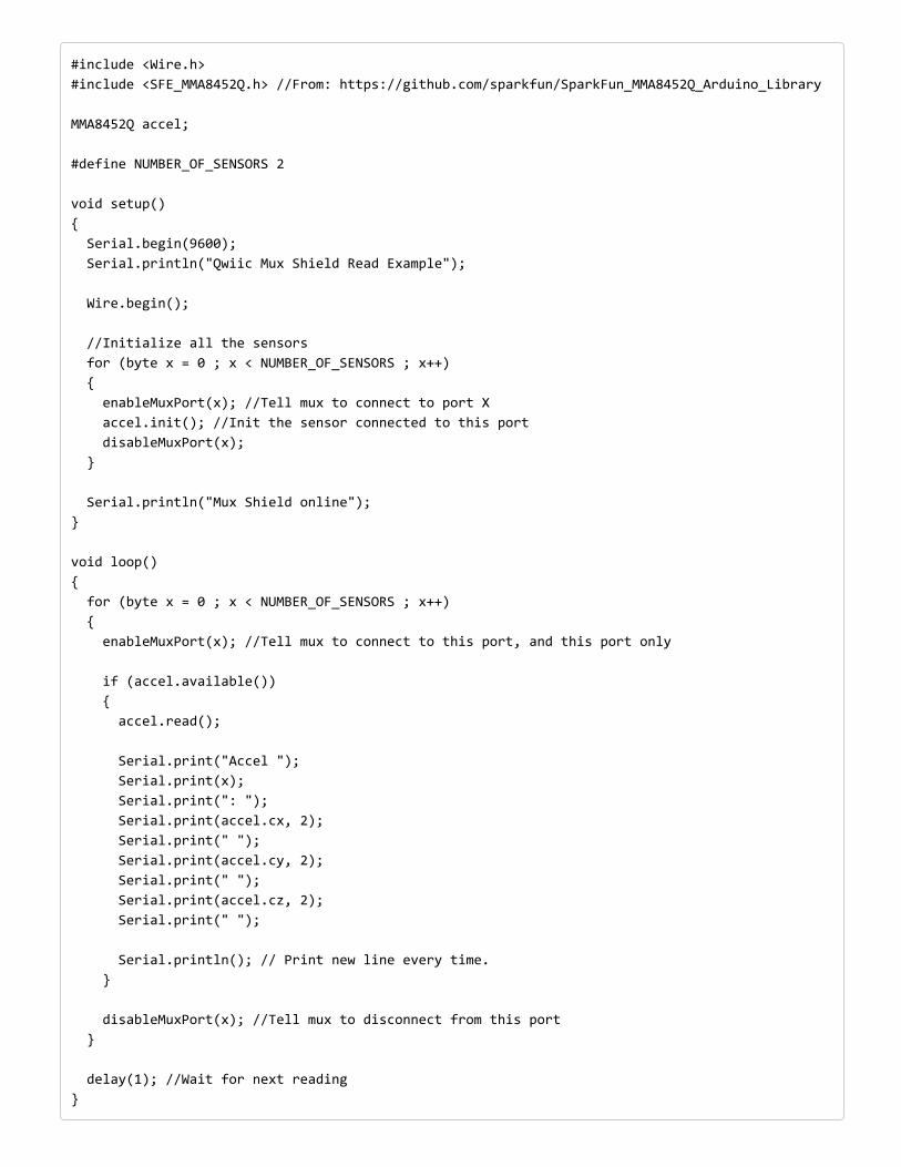
sensor on that channel. The below example code shows how to read from two MMA8452Q accelerometers.
#include <Wire.h> #include <SFE_MMA8452Q.h> //From: https://github.com/sparkfun/SparkFun_MMA8452Q_Arduino_Library MMA8452Q accel; #define NUMBER_OF_SENSORS 2 void setup() { Serial.begin(9600); Serial.println("Qwiic Mux Shield Read Example"); Wire.begin(); //Initialize all the sensors for (byte x = 0 ; x < NUMBER_OF_SENSORS ; x++) { enableMuxPort(x); //Tell mux to connect to port X accel.init(); //Init the sensor connected to this port disableMuxPort(x); } Serial.println("Mux Shield online"); } void loop() { for (byte x = 0 ; x < NUMBER_OF_SENSORS ; x++) { enableMuxPort(x); //Tell mux to connect to this port, and this port only if (accel.available()) { accel.read(); Serial.print("Accel "); Serial.print(x); Serial.print(": "); Serial.print(accel.cx, 2); Serial.print(" "); Serial.print(accel.cy, 2); Serial.print(" "); Serial.print(accel.cz, 2); Serial.print(" "); Serial.println(); // Print new line every time. } disableMuxPort(x); //Tell mux to disconnect from this port } delay(1); //Wait for next reading }
With the example provided, you should be able to read two I C sensors with the same address on the same bus!Try opening up the Arduino Serial Monitor set to 9600 baud in order to read the sensor values.
Resources and Going FurtherNow that you’ve successfully got your Qwiic mux listening to all of those concurrent addresses, it’s time toincorporate it into your own project!
For more information, check out the resources below:
Schematic (PDF)Eagle Files (ZIP)Datasheet
TCA9548APCA9548A
Qwiic Landing PageExample Code
Arduino Example (ZIP)MMA8452Q Arduino Library
GitHub RepoSparkFun Product Showcase: Qwiic Mux
Gist: Light Spectrogram
Need even more inspiration for your next project? Check out some of these related tutorials:
2
CCS811/BME280 (Qwiic) Environmental ComboBreakout Hookup GuideSense various environmental conditions such astemperature, humidity, barometric pressure, eCO2 andtVOCs with the CCS811 and BME280 combo breakoutboard.
Qwiic Distance Sensor (RFD77402) HookupGuideThe RFD77402 uses an infrared VCSEL (VerticalCavity Surface Emitting Laser) TOF (Time of Flight)module capable of millimeter precision distancereadings up to 2 meters. It’s also part of SparkFun’sQwiic system, so you won’t have to do any soldering tofigure out how far away things are.

Qwiic Accelerometer (MMA8452Q) HookupGuideFreescale’s MMA8452Q is a smart, low-power, three-axis, capacitive micro-machined accelerometer with 12-bits of resolution. It’s perfect for any project that needsto sense orientation or motion. We’ve taken thataccelerometer and stuck it on a Qwiic-Enabledbreakout board to make interfacing with the tiny, QFNpackage a bit easier.
Qwiic Magnetometer (MLX90393) HookupGuideFigure out how magnetic fields are oriented, all withouthaving to solder a thing.