Embed Size (px)
Citation preview
LUDWIG BUILDINGS
QUOTATION/PURCHASE ORDER GUIDE
Publication LMP-003
LUDWIG BUILDINGS
521 TIMESAVER AVENUE
HARAHAN, LA. 70123
QUOTATION/PURCHASE ORDER
GUIDE
Publication: LMP-003
Revision: 5
Effective Date: Dec 06
i
LUDWIG BUILDINGS
Preface
Review the following excerpt from the 2006 MBMA Metal Building Systems Manual (IV. Common Industry Practices, pages 321 – 326) for the responsibilities of you the Purchaser to provide design information to Ludwig Buildings.
“SECTION 3 – Design of a Metal Building System
3.1 Design Responsibility It is the responsibility of the Manufacturer, through the Manufacturer's Engineer, to design the Metal Building System to meet the specifications including the design criteria and design loads incorporated by the Builder into the Order Documents. The Manufacturer is not responsible for making an independent determination of any local codes or any other requirements not part of the Order Documents. The Manufacturer is responsible only for the structural design of the Metal Building System it sells to the Builder. The Manufacturer or the Manufacturer's Engineer is not the Design Professional or Engineer of Record for the Construction Project. The Manufacturer is not responsible for the design of any components or materials not sold by it or their interface and connection with the Metal Building System unless such design responsibility is specifically required by the Order Documents. Therefore, it is highly recommended that the End Customer hire a Design Professional or Engineer of Record (EOR) who would be responsible for specifying the design criteria for the Metal Building System to be used by the Builder and Manufacturer including all applicable design loads. The EOR is also typically responsible for the design of any components or materials not sold by the Manufacturer and the interface and connection with the Metal Building System. The EOR can also provide valuable inspection services to the End Customer to ensure that the project is constructed according to the Manufacturer’s erection drawings. While not recommended practice, if the End Customer does not retain a Design Professional or EOR, it is the responsibility of the End Customer to specify the design criteria to be used for the Metal Building System including all applicable design loads. It is the responsibility of the Builder to interpret all aspects of the End Customer’s specifications and incorporate the appropriate specifications, design criteria, and design loads into the Order Documents submitted to the Manufacturer. When specified by the Order Documents, the Manufacturer is responsible for supplying adequate evidence of compliance with the specifications, design criteria, and design loads, and other specified information necessary for the Builder or Design Professional to incorporate the Metal Building System into the Construction Project. In the event of discrepancy between the plans and specifications for the Metal Building System, the plans govern. In the event of discrepancy between scaled dimensions and numerical dimensions on the plans, included as part of the Order Documents, the numerical dimensions govern.
QUOTATION/PURCHASE ORDER
GUIDE
Publication: LMP-003
Revision: 5
Effective Date: Dec 06
ii
LUDWIG BUILDINGS
3.2 End Customer Responsibility 3.2.1 General The End Customer is responsible for identifying all applicable building codes, zoning codes, or other regulations applicable to the Construction Project, including the Metal Building System. It is the responsibility of the End Customer to prepare complete specifications including the applicable design criteria, codes, standards, and regulations, and all the design loads or other requirements which affect the design or erection of the Metal Building System. The following information must be supplied to the Builder by the End Customer or the Design Professional. This information must, in turn, be supplied to the Manufacturer by the Builder:
1. The building geometric requirements such as length, width, height, roof shape and slope, and clearance requirements, both vertical and horizontal.
2. The applicable code or standard that describes the application of design loads to the Metal Building System.
3. The applicable design loads including Live, Snow, Wind, Seismic, Collateral and Auxiliary loads, including information concerning Collateral and Auxiliary loads required by the Manufacturer to enter the order. Unless design loads or conditions are specifically set out in the Order Documents, the Manufacturer assumes that no such loads or conditions exist.
4. All coefficients or factors (for example; Exposure, Importance, Building Use, etc.) necessary to adjust general or commonly used values in the specified design standard or code for the local site conditions and specified conditions of use.
5. Site and construction conditions that affect design criteria such as conditions causing snow drifting, including location of adjacent structures.
6. Open wall conditions. 7. All information necessary to ensure that the Metal Building System can be designed to comply
with the specified code or standards and is compatible with other materials used on the Construction Project.
8. All serviceability criteria limiting vertical or horizontal deflection of components or gross building drift that are necessary to ensure that the stiffness of the Metal Building Systems is suitable for its specific conditions of use and compatible with materials not included in the Metal Building System.
9. In the design of the Metal Building System, the owner is responsible for providing clearances and adjustments of material furnished by other trades to accommodate all of the tolerances of the Metal Building System.
QUOTATION/PURCHASE ORDER
GUIDE
Publication: LMP-003
Revision: 5
Effective Date: Dec 06
iii
LUDWIG BUILDINGS
3.2.2 Foundation Design The Manufacturer is not responsible for the design, materials and workmanship of the foundation. Anchor bolt plans prepared by the Manufacturer are intended to show only location, diameter, and projection of anchor bolts required to attach the Metal Building System to the foundation. The Manufacturer is responsible for providing to the Builder the loads imposed by the Metal Building System on the foundation. It is the responsibility of the End Customer to ensure that adequate provisions are made for specifying bolt embedment, bearing angles, tie rods, and/or other associated items embedded in the concrete foundation, as well as foundation design for the loads imposed by the Metal Building System, other imposed loads, and the bearing capacity of the soil and other conditions of the building site. This is typically the responsibility of the Design Professional or Engineer of Record, which is another reason that their involvement in the Construction Project from the outset is highly recommended.
3.2.3 Ventilation, Condensation and Energy Conservation The Manufacturer does not design or check a ventilation or energy conservation system unless required by the Order Documents and is not responsible for the adequacy of specified ventilation and energy conservation components. The End Customer assures that adequate provisions are made for ventilation, condensation, and energy conservation requirements.
3.2.4 Framed Openings The design of framed openings in accordance with the design loads specified by the Order Documents is the responsibility of the Manufacturer. Design of materials supplied by others to be installed in these openings is the responsibility of the End Customer. It is the responsibility of the End Customer to supply to the Builder design loads and other requirements that affect the design of the Metal Building System and its compatibility with other materials. The Builder must incorporate these requirements into the Order Documents.
3.2.5 Effect on Existing Buildings The Manufacturer does not investigate the influence of the Metal Building System on existing buildings or structures. The End Customer assures that such buildings and structures are adequate to resist snow drifts or other conditions as a result of the presence of the Metal Building System.
3.2.6 Inspection The Manufacturer is not responsible for inspection of a Construction Project unless this is incorporated into the Order Documents. Typically, a Manufacturer is limited because of logistical constraints as well as not having the expertise in inspection services. Furthermore, a Manufacturer is not in the best position to inspect the work of the Builder who is the Manufacturer’s Customer. Ideally, an End Customer should utilize the inspection services of the Engineer of Record for the project to provide this important function.
QUOTATION/PURCHASE ORDER
GUIDE
Publication: LMP-003
Revision: 5
Effective Date: Dec 06
iv
LUDWIG BUILDINGS
3.3 Manufacturer's Responsibility 3.3.1 General The Manufacturer is responsible for the design of the Metal Building System as defined by the Order Documents, and for providing engineering data and approval drawings, as required by the Order Documents.
3.3.2 Engineering Data The Manufacturer provides a letter of design certification, design calculations, or other engineering data specified in the Order Documents. The letter of design certification and design calculations are sealed by the Manufacturer's Engineer who is a Registered Professional Engineer in the juristiction where the Construction Project is located. Erection drawings are not required to be sealed. In any event, the supplying of sealed engineering data and drawings for the Metal Building System does not imply or constitute an agreement that the Manufacturer or Manufacturer's Engineer is acting as the Engineer of Record or Design Professional for a Construction Project. The letter of design certification states the order number and lists the design criteria including design codes, standards, loads and other design information supplied to the Manufacturer as provided in Paragraph 3.2, and certifies that the structural design complies with the requirements of the Order Documents. Design calculations include the information contained in the letter of certification plus structural design data for the framing members and covering of the Metal Building System necessary to show compliance with the Order Documents. The structural design data includes magnitude and location of design loads and support conditions, material properties, and the type and size of major structural members. Design calculations may be manually or computer generated at the discretion of the Manufacturer, and are in accordance with the Manufacturer's usual procedures and standards unless otherwise specified by the Order Documents. Testing by an independent laboratory or by the Manufacturer may be conducted on components and systems at the discretion of the Manufacturer. Reports of such tests may be part of the adequate evidence necessary to show compliance with the Order Documents.
3.3.3 Approval Documents When required by Order Documents, approval documents including plans, design calculations, and other specified information are furnished by the Manufacturer to the Builder for approval. In order for the Manufacturer to proceed with preparation of fabrication drawings and the manufacture of the Metal Building System, the Builder returns one set of approval documents to the Manufacturer with a notation of outright approval or approval subject to the Builder's requested changes or corrections.
QUOTATION/PURCHASE ORDER
GUIDE
Publication: LMP-003
Revision: 5
Effective Date: Dec 06
v
LUDWIG BUILDINGS
Approval by the Builder without any changes or corrections affirms that the Manufacturer has correctly interpreted the Builder's requirements as set forth in the Order Documents. If there are differences between the approval documents as prepared by the Manufacturer and the Order Documents, the approval documents take precedence. If the Builder returns the approval documents with requested changes, additions or corrections, the documents shall be considered as a request to modify the Order Documents and must be agreed to by the Manufacturer pursuant to the provisions of Paragraph 2.2. If the approval documents with requested changes, additions or corrections are not returned to the Manufacturer and approved pursuant to the provisions of Paragraph 2.2, the requested changes, additions or corrections are not binding on the Manufacturer. The Builder may incorporate the Manufacturer's approval data into documents submitted for the approval of the Contractor, General Contractor, or End Customer. In this event, only the Builder's approval or the Builder's requested changes and corrections are applicable to the Order Documents.
3.3.4 Plans When approval documents are not required or the Builder has approved the Manufacturer's approval documents, the Manufacturer prepares fabrication drawings and provides the Builder with prints of the final anchor bolt plans, erection drawings and erection instructions.
3.3.5 Fabrication Drawings Fabrication drawings are not furnished by the Manufacturer.
3.3.6 Quality Assurance Manufacturers are responsible for assuring quality in the Metal Building System. A quality control program verified by an outside inspection agency, similar to the AISC-MB Certification program described in Section VI of this Manual, will satisfy this responsibility.”
QUOTATION/PURCHASE ORDER
GUIDE
Publication: LMP-003
Revision: 5
Effective Date: Dec 06
vi
LUDWIG BUILDINGS
FOREWORD
The Ludwig Buildings Quotation/Purchase Order Guide has been prepared to assist customers in
clearly describing their metal building system requirements to Ludwig sales personnel. This
guide includes explanations and definitions of various factors that affect the design of the metal
building system.
If the End Customer hires a Design Professional for a construction project, it is the responsibility
of the Design Professional to specify the design criteria for the Metal Building System to be used
by the Purchaser and the Manufacturer including all applicable design loads.
If the End Customer does not retain a Design Professional, it is the responsibility of the End
Customer to specify the design criteria to be used for the Metal Building System including all
applicable design loads.
In any event, it is the responsibility of the Purchaser to interpret all aspects of the End Customer's
specifications and incorporate the appropriate specifications, design criteria, and design loads
into the Order Documents submitted to the Manufacturer.
It is the responsibility of the Manufacturer, through the Manufacturer's Engineer, to design the
Metal Building System to meet the specifications including the design criteria and design loads
incorporated by the Purchaser into the Order Documents. The Manufacturer is not responsible
for making an independent determination of any local codes or any other requirements not part of
the Order Documents.
The Ludwig Quotation/Purchase Order shall be the primary operating instrument in the
contractual agreement between the Purchaser and Ludwig Buildings, LLC (referred to as Ludwig
Buildings or Ludwig) and shall supersede all other documents.
Please ensure accurate completion of all sections of the Ludwig Quotation/Purchase Order.
Ludwig will make no assumptions on any areas that may be left incomplete.
QUOTATION/PURCHASE ORDER
GUIDE
Publication: LMP-003
Revision: 5
Effective Date: Dec 06
vii
LUDWIG BUILDINGS
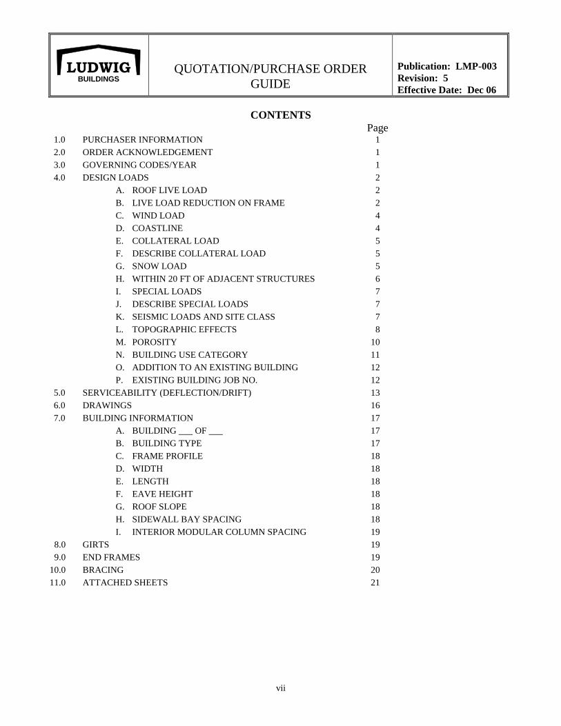
CONTENTS
Page 1.0 PURCHASER INFORMATION 1
2.0 ORDER ACKNOWLEDGEMENT 1
3.0 GOVERNING CODES/YEAR 1
4.0 DESIGN LOADS 2
A. ROOF LIVE LOAD 2
B. LIVE LOAD REDUCTION ON FRAME 2
C. WIND LOAD 4
D. COASTLINE 4
E. COLLATERAL LOAD 5
F. DESCRIBE COLLATERAL LOAD 5
G. SNOW LOAD 5
H. WITHIN 20 FT OF ADJACENT STRUCTURES 6
I. SPECIAL LOADS 7
J. DESCRIBE SPECIAL LOADS 7
K. SEISMIC LOADS AND SITE CLASS 7
L. TOPOGRAPHIC EFFECTS 8
M. POROSITY 10
N. BUILDING USE CATEGORY 11
O. ADDITION TO AN EXISTING BUILDING 12
P. EXISTING BUILDING JOB NO. 12
5.0 SERVICEABILITY (DEFLECTION/DRIFT) 13
6.0 DRAWINGS 16
7.0 BUILDING INFORMATION 17
A. BUILDING ___ OF ___ 17
B. BUILDING TYPE 17
C. FRAME PROFILE 18
D. WIDTH 18
E. LENGTH 18
F. EAVE HEIGHT 18
G. ROOF SLOPE 18
H. SIDEWALL BAY SPACING 18
I. INTERIOR MODULAR COLUMN SPACING 19
8.0 GIRTS 19
9.0 END FRAMES 19
10.0 BRACING 20
11.0 ATTACHED SHEETS 21
QUOTATION/PURCHASE ORDER
GUIDE
Publication: LMP-003
Revision: 4
Effective Date: June 06
viii
LUDWIG BUILDINGS
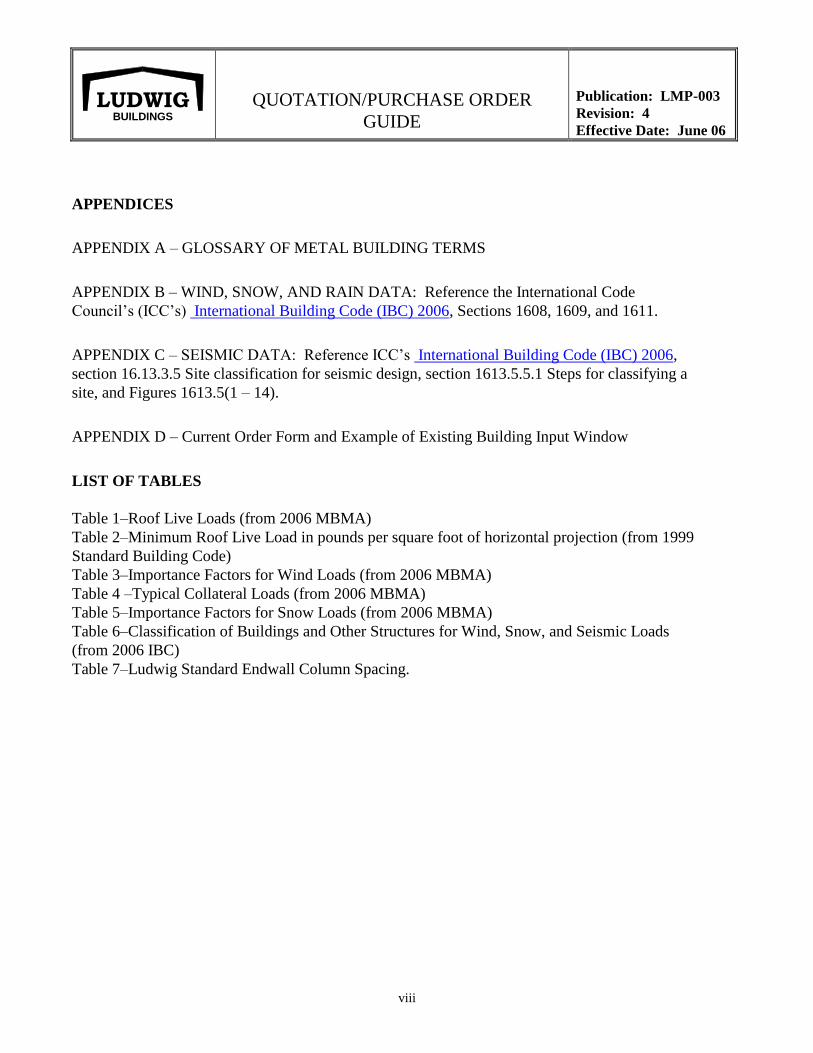
APPENDICES
APPENDIX A – GLOSSARY OF METAL BUILDING TERMS
APPENDIX B – WIND, SNOW, AND RAIN DATA: Reference the International Code
Council’s (ICC’s) International Building Code (IBC) 2006, Sections 1608, 1609, and 1611.
APPENDIX C – SEISMIC DATA: Reference ICC’s International Building Code (IBC) 2006,
section 16.13.3.5 Site classification for seismic design, section 1613.5.5.1 Steps for classifying a
site, and Figures 1613.5(1 – 14).
APPENDIX D – Current Order Form and Example of Existing Building Input Window
LIST OF TABLES
Table 1–Roof Live Loads (from 2006 MBMA)
Table 2–Minimum Roof Live Load in pounds per square foot of horizontal projection (from 1999
Standard Building Code)
Table 3–Importance Factors for Wind Loads (from 2006 MBMA)
Table 4 –Typical Collateral Loads (from 2006 MBMA)
Table 5–Importance Factors for Snow Loads (from 2006 MBMA)
Table 6–Classification of Buildings and Other Structures for Wind, Snow, and Seismic Loads
(from 2006 IBC)
Table 7–Ludwig Standard Endwall Column Spacing.
QUOTATION/PURCHASE ORDER
GUIDE
Publication: LMP-003
Revision: 4
Effective Date: June 06
1
LUDWIG BUILDINGS
All Sections of the Quotation/Purchase Order must be complete. Those
that do not apply must be noted as N/A.
1.0 Purchaser Information
Fill in all blanks and check the appropriate boxes.
2.0 Order Acknowledgement
Leave blank. This block will be completed by Ludwig.
3.0 Governing Codes/Year
IBC International Building Code
SBC Standard Building Code
FBC Florida Building Code
ASCE 7 (ANSI) American Society of Civil Engineers Committee No. 7 (American
National Standards Institute)
BOCA Building Officials and Code Administrators
UBC Uniform Building Code
The Purchaser is responsible for identifying the governing code to be used in the design
of the metal building system. The building code will describe the design criteria and the
building loads that should be considered in the design. Consult your local code authority
to ensure that the proper code requirements will be used in the building design. Check
the appropriate code and write in the year of the code.
The Purchaser is responsible for identifying the exposure to be used in the design of the
metal building system. Ludwig will use exposure B in its quotation if not informed
otherwise. The Purchaser must notify Ludwig if a different exposure is to be used.
Exposure: Check the appropriate letter according to the following definitions taken
from ASCE-7. These wind related exposure values are applicable to IBC, ASCE 7,
BOCA, FBC, and UBC only:
Exposure B Urban and Suburban areas, towns, city outskirts, wooded areas, and
rolling terrains. (Exposure A is for centers of large cities and very
rough terrain. If your building fits in Exposure A category, check
Exposure B, which is more stringent than A.)
Exposure C Flat and open country, grassland, and shoreline in hurricane prone
regions.
Exposure D Flat, unobstructed areas exposed to wind blowing over open bodies
of water (excluding shorelines in hurricane prone regions for a
distance of at least 1 mile, but including inland waterways).
QUOTATION/PURCHASE ORDER
GUIDE
Publication: LMP-003
Revision: 4
Effective Date: June 06
2
LUDWIG BUILDINGS
4.0 Design Loads
Design loads are the loads to be specified in the Quotation/Purchase Order (the contract
document) that the metal building system will be designed to safely resist. Values and
calculations for design loads are based on the particular building code specified by the
Purchaser. MBMA examples from the MBMA Metal Building Systems Manual1 are
used in this guide.
The Purchaser is responsible for ensuring all loads stated on the Quotation/Purchase
Order are in accordance with local code requirements. The Purchaser is responsible for
contacting the local authorities to verify design loads. Ludwig’s design policy dictates
that the design shall follow the local code requirements. In the absence of any local
code, the MBMA design practices (which uses IBC) shall be applied. The Purchaser
shall refer to the Wind, Snow, Seismic, and Rain Data by U.S. County chart, Chapter IX
of the 2006 MBMA Metal Building Systems Manual or any other applicable sections
when using MBMA design practices.
A. Roof Live Load. Those loads produced: (1) during maintenance by workers,
equipment, and materials, and (2) during the life of the structure by movable objects
such as planters and by people and do not include wind, snow, seismic, or dead
loads.
Indicate the roof live load in pounds per square foot (psf). The purchaser shall
contact the local authorities for the proper live load. The roof live load is used in
purlin design (gage, spacing, and lap) and roof panel design.
B. Live Load Reduction on Frame. Check the box if live load reduction on the frame
is NOT allowed. The Purchaser must consult the local code to determine if live load
reduction on frame is allowed. If reduction is allowed in accordance with MBMA,
use Table 1–Roof Live Loads taken from the 2006 MBMA Metal Building Systems
Manual. If the local code requires SBC, follow Table 2–Minimum Roof Live Load
taken from the 1999 SBC (Table 1604.6).
Note that there are differences between MBMA and SBC, particularly the
differences in the second and third tributary loaded area categories: MBMA’s
second category ends at 599 ft2, whereas SBC’s second category ends at 600 ft
2 and
MBMA’s third category begins at 600 ft2, whereas SBC’s third category begins at
601 ft2.
To use both MBMA and SBC tables, you must calculate tributary loaded area (or At)
in ft2 for any structural member of your building. To do so, multiply the width x the
length of the area that the roof structural members support (that is, the bay width x
the building width). After determining At, go to the appropriate roof slope row in the
table to determine live load reduction. See the examples that follow.
1 From Metal Building Manufacturer’s Association (MBMA) Metal Building Systems Manual 2002.
QUOTATION/PURCHASE ORDER
GUIDE
Publication: LMP-003
Revision: 3
Effective Date: Dec 03
3
LUDWIG BUILDINGS
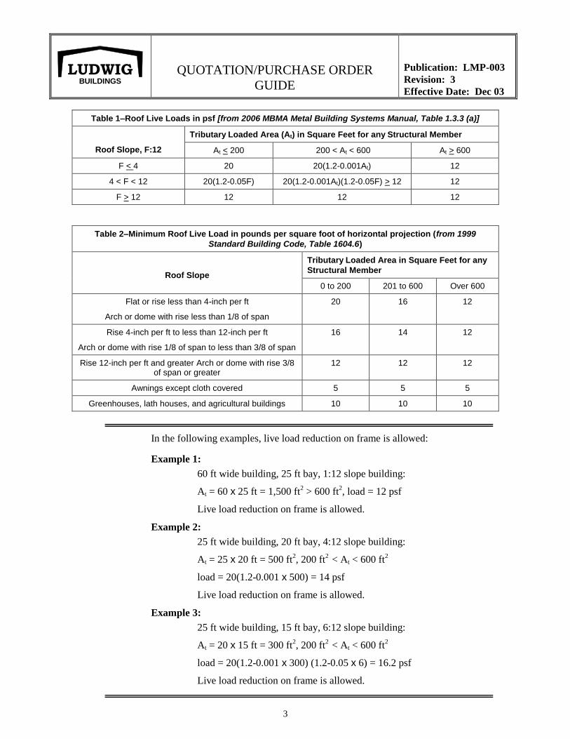
Table 1–Roof Live Loads in psf [from 2006 MBMA Metal Building Systems Manual, Table 1.3.3 (a)]
Roof Slope, F:12
Tributary Loaded Area (At) in Square Feet for any Structural Member
At < 200 200 < At < 600 At > 600
F < 4 20 20(1.2-0.001At) 12
4 < F < 12 20(1.2-0.05F) 20(1.2-0.001At)(1.2-0.05F) > 12 12
F > 12 12 12 12
Table 2–Minimum Roof Live Load in pounds per square foot of horizontal projection (from 1999
Standard Building Code, Table 1604.6)
Roof Slope
Tributary Loaded Area in Square Feet for any
Structural Member
0 to 200 201 to 600 Over 600
Flat or rise less than 4-inch per ft
Arch or dome with rise less than 1/8 of span
20 16 12
Rise 4-inch per ft to less than 12-inch per ft
Arch or dome with rise 1/8 of span to less than 3/8 of span
16 14 12
Rise 12-inch per ft and greater Arch or dome with rise 3/8 of span or greater
12 12 12
Awnings except cloth covered 5 5 5
Greenhouses, lath houses, and agricultural buildings 10 10 10
In the following examples, live load reduction on frame is allowed:
Example 1:
60 ft wide building, 25 ft bay, 1:12 slope building:
At = 60 x 25 ft = 1,500 ft2 > 600 ft
2, load = 12 psf
Live load reduction on frame is allowed.
Example 2:
25 ft wide building, 20 ft bay, 4:12 slope building:
At = 25 x 20 ft = 500 ft2, 200 ft
2 < At < 600 ft
2
load = 20(1.2-0.001 x 500) = 14 psf
Live load reduction on frame is allowed.
Example 3:
25 ft wide building, 15 ft bay, 6:12 slope building:
At = 20 x 15 ft = 300 ft2, 200 ft
2 < At < 600 ft
2
load = 20(1.2-0.001 x 300) (1.2-0.05 x 6) = 16.2 psf
Live load reduction on frame is allowed.
QUOTATION/PURCHASE ORDER
GUIDE
Publication: LMP-003
Revision: 4
Effective Date: June 06
4
LUDWIG BUILDINGS
C. Wind Load. The loads caused by the wind from any horizontal direction.
Indicate wind load in miles per hour (MPH).
The Purchaser is required to consult local authorities to determine the proper wind
load used for building design.
Wind Importance factors used in design will be based on Building Use Category (as
shown in Table 6 of this guide).
In the absence of local code, the Purchaser may consult the Wind, Snow, Seismic,
and Rain Data by U.S. County chart, Chapter IX of the 2006 MBMA Metal Building
Systems Manual.
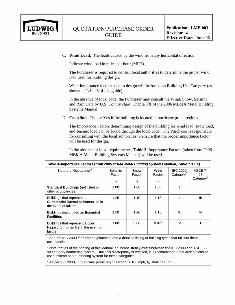
D. Coastline. Choose Yes if the building is located in hurricane prone regions.
The Importance Factors determining design of the building for wind load, snow load,
and seismic load can be found through the local code. The Purchaser is responsible
for consulting with the local authorities to ensure that the proper importance factor
will be used for design.
In the absence of local requirements, Table 3–Importance Factors (taken from 2006
MBMA Metal Building Systems Manual) will be used.
Table 3–Importance Factors (from 2006 MBMA Metal Building Systems Manual, Table 1.3.1 a)
Nature of Occupancy1 Seismic
Factor
IE
Snow Factor
IS
Wind Factor
IW
IBC 2000 Category
2
ASCE 7-98
Category2
Standard Buildings (not listed in other occupancies)
1.00 1.00 1.00 I II
Buildings that represent a
Substantial Hazard to human life in the event of failure
1.25 1.10 1.15 II III
Buildings designated as Essential
Facilities
1.50 1.20 1.15 III IV
Buildings that represent a Low
Hazard to human life in the event of failure
1.00 0.80 0.873 IV I
1 See the IBC 2000 for further explanation and a detailed listing of building types that fall into these
occupancies.
2 Note that as of the printing of this Manual, an inconsistency exists between the IBC 2000 and ASCE 7-
98 category numbering system. Until this discrepancy is rectified, it is recommended that descriptions be used instead of a numbering system for these categories.
3 As per IBC 2000, in hurricane prone regions with V > 100 mph, IW shall be 0.77.
QUOTATION/PURCHASE ORDER
GUIDE
Publication: LMP-003
Revision: 4
Effective Date: June 06
5
LUDWIG BUILDINGS
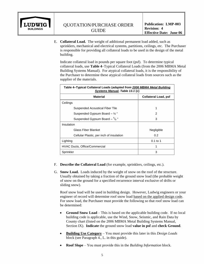
E. Collateral Load. The weight of additional permanent load added, such as
sprinklers, mechanical and electrical systems, partitions, ceilings, etc. The Purchaser
is responsible for providing all collateral loads to be used in the design of the metal
building.
Indicate collateral load in pounds per square foot (psf). To determine typical
collateral loads, use Table 4–Typical Collateral Loads (from the 2006 MBMA Metal
Building Systems Manual). For atypical collateral loads, it is the responsibility of
the Purchaser to determine these atypical collateral loads from sources such as the
supplier of the materials.
Table 4–Typical Collateral Loads (adapted from 2006 MBMA Metal Building
Systems Manual, Table 13.1 (c)
Material Collateral Load, psf
Ceilings
Suspended Acoustical Fiber Tile
Suspended Gypsum Board – ½ "
Suspended Gypsum Board – 5/8 "
1
2
3
Insulation
Glass Fiber Blanket
Cellular Plastic, per inch of insulation
Negligible
0.2
Lighting 0.1 to 1
HVAC Ducts, Office/Commercial 1
Sprinkler 3
F. Describe the Collateral Load (for example, sprinklers, ceilings, etc.).
G. Snow Load. Loads induced by the weight of snow on the roof of the structure.
Usually obtained by taking a fraction of the ground snow load (the probable weight
of snow on the ground for a specified recurrence interval exclusive of drifts or
sliding snow).
Roof snow load will be used in building design. However, Ludwig engineers or your
engineer of record will determine roof snow load based on the applied design code.
For snow load, the Purchaser must provide the following so that roof snow load can
be determined:
Ground Snow Load – This is based on the applicable building code. If no local
building code is applicable, use the Wind, Snow, Seismic, and Rain Data by
County chart (listed on the 2006 MBMA Metal Building Systems Manual,
Section IX). Indicate the ground snow load value in psf and check Ground.
Building Use Category – You must provide this later in this Design Loads
block (see Paragraph 4., L. in this guide).
Roof Slope – You must provide this in the Building Information block.
QUOTATION/PURCHASE ORDER
GUIDE
Publication: LMP-003
Revision: 4
Effective Date: June 06
6
LUDWIG BUILDINGS
Heated or Unheated Building – Check Yes if the building is heated or No if the
building is not heated. This is important in determining Roof Snow Load used in
Method 1.
Roof Type – Check the roof type from these choices:
Exposed Roof – Roofs exposed on all sides with no shelter afforded by
terrain, higher structures, or trees. Roofs that contain
several large pieces of mechanical equipment or other
obstructions are not in this category.
Normal Roof – All roofs except Exposed Roofs or Sheltered Roofs.
Sheltered – Roofs located tight in among trees that do no lose their
leaves in winter qualify as shelters.
If your engineer determines the roof snow load value by governing design code, check
Roof to indicate that the snow load value you provide is for roof snow load. If the snow load
value that you provide is for ground snow load, indicate ground snow load by checking that
box.
H. Within 20 ft of Adjacent Structures. Indicate if any Stepped Elevations and/or
Higher or Lower Structures or Site Features are within 20 ft of the proposed
building. If yes, show the relationship on the Building Layout Sheet. This is
important in calculating snow drift (the snow accumulation at a height discontinuity).
On the Building Layout Sheet, indicate whether or not a snow drift condition exists
by marking the Yes or No checkbox. Use the Building Layout Sheet to provide
information about the adjacent stepped elevations, structure, or site features such as:
1. Hr – the eave height difference between the new and existing buildings.
2. Wb – the dimension of the existing building that is perpendicular to the
change in roof elevation between the buildings.
3. Separation – the separation between buildings. If the buildings have a
common wall, write "0."
4. Roof Slope – The tangent of the angle that a roof surface makes with the
horizontal, usually expressed in units of vertical rise to 12 units of horizontal
run (e.g., 2:12).
5. Additional information – Include information such as ridge orientation,
direction of slope, and any additional information.
QUOTATION/PURCHASE ORDER
GUIDE
Publication: LMP-003
Revision: 3
Effective Date: Dec 06
7
LUDWIG BUILDINGS
I. Special Loads. Indicate if any special loads are to be incorporated into building
design by checking the appropriate box: either crane loads, mezzanine loads, point
loads, or other loads.
J. Describe Special Load. Indicate and attach the appropriate Ludwig form (either
Crane Data Sheet, Mezzanine Data Sheet, or Point Loads Sheet, or other loads on
page 3 of the order form) to describe special loads. To determine crane loads and
point loads, contact the manufacturer of the equipment (for example, cranes, HVAC
systems, etc.). To determine mezzanine loads, refer to page 2 of the Ludwig
Mezzanine Data Sheet.
K. Seismic.
Seismic Loads. Lateral loads acting on a structural system due to the action of an
earthquake.
Seismic Loads are expressed with Peak Acceleration (Aa) and Effective Peak
Velocity Related Acceleration Value (Av). To determine Aa and Av, use Appendix B
(of this Guide) – Wind, Snow, Seismic, and Rain Data by County Chart taken from
2006 MBMA Metal Building Systems Manual, Chapter IX.
If your building is being designed for the International Building Code (IBC), fill
in Ss, S1, and Site Class.
Ss = the mapped maximum considered earthquake spectral response acceleration at
short periods.
S1 = the mapped maximum considered earthquake spectral response acceleration at
1-second period.
To determine Ss and S1, use Figures 1615(1) and (2) from IBC (see Appendix C of
this Guide). Where a site is between contours, straight line interpolation or the value
of the higher contour shall be used.
Site Class.
Site class, which is dictated by soil profile type, is determined in accordance with
Section 1615.1.5 of IBC 2003. Use Table 1615.1.5 – Site Classification from IBC
located in Appendix C of this Guide. If a customer does not know the site class,
input “Unknown.” If a customer inputs “Unknown,” and cannot provide sufficient
detail to determine the site class, the customer will be notified that Class D will be
used in Ludwig design (ASCE 7-02, Sec. 9.4.1.2.1).
QUOTATION/PURCHASE ORDER
GUIDE
Publication: LMP-003
Revision: 5
Effective Date: Dec 06
8
LUDWIG BUILDINGS
L. Topographic Effects.
Wind Speed-Up over Hills, Ridges, and Escarpments. Wind speed-up effects at isolated hills, ridges, and
escarpments constituting abrupt changes in the general topography, located in any exposure category, shall be
included in the design when buildings and other site conditions and locations of structures meet all of the
following conditions:
1. The hill, ridge, or escarpment is isolated and unobstructed upwind by other similar topographic features
of comparable height for 100 times the height of the topographic feature (100 H) or 2 miles (3.22 km),
whichever is less. The distance shall be measured horizontally from the point at which the height H of
the hill, ridge, or espcarpment is determined.
2. The hill, ridge, or escarpment protrudes above the height of upwind terrain features within a 2-mile
(3.22-km) radius in any quadrant by a factor of two or more;
3. The structure is located as shown in Figure 6-4 in the upper half of a hill or ridge or near the crest of an
escarpment;
4. H/Lh > 0.2; and
5. H is greater than or equal to 15 ft (4.5 m) for Exposures C and D and 60 ft (18 m) for Exposure B.
If the location of a building meets all of the above five (5) conditions, the customer must provide the following
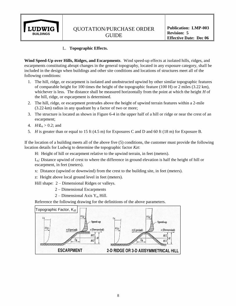
location details for Ludwig to determine the topographic factor Kzt:
H: Height of hill or escarpment relative to the upwind terrain, in feet (meters).
Lh: Distance upwind of crest to where the difference in ground elevation is half the height of hill or
escarpment, in feet (meters).
x: Distance (upwind or downwind) from the crest to the building site, in feet (meters).
z: Height above local ground level in feet (meters).
Hill shape: 2 – Dimensional Ridges or valleys.
2 – Dimensional Escarpments
2 – Dimensional Axis Ym Hill.
Reference the following drawing for the definitions of the above parameters.
Topographic Factor, Kzt
QUOTATION/PURCHASE ORDER
GUIDE
Publication: LMP-003
Revision: 5
Effective Date: Dec 06
9
LUDWIG BUILDINGS
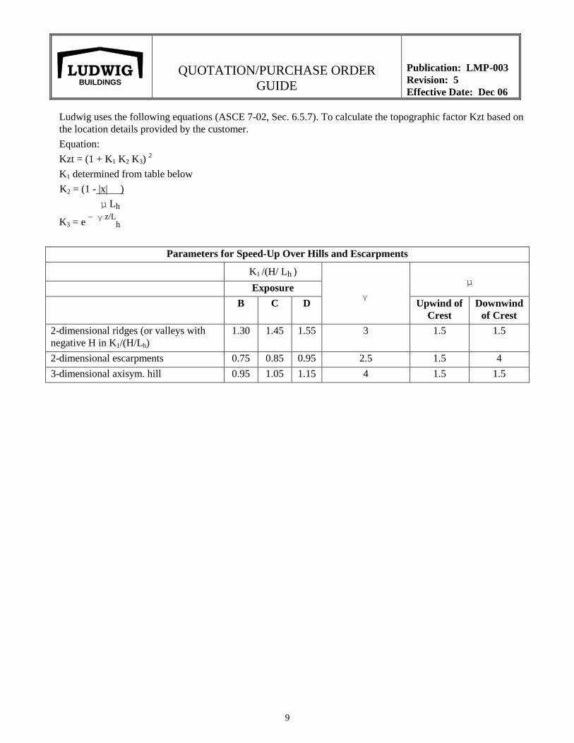
Ludwig uses the following equations (ASCE 7-02, Sec. 6.5.7). To calculate the topographic factor Kzt based on
the location details provided by the customer.
Equation:
Kzt = (1 + K1 K2 K3) 2
K1 determined from table below
K2 = (1 - |x| )
µ Lh
K3 = e – γ z/L
h
Parameters for Speed-Up Over Hills and Escarpments
K1 /(H/ Lh )
γ
µ Exposure
B C D Upwind of
Crest
Downwind
of Crest
2-dimensional ridges (or valleys with
negative H in K1/(H/Lh)
1.30 1.45 1.55 3 1.5 1.5
2-dimensional escarpments 0.75 0.85 0.95 2.5 1.5 4
3-dimensional axisym. hill 0.95 1.05 1.15 4 1.5 1.5
QUOTATION/PURCHASE ORDER
GUIDE
Publication: LMP-003
Revision: 5
Effective Date: Dec 06
10
LUDWIG BUILDINGS
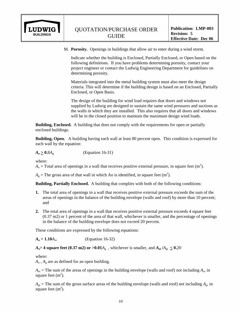
M. Porosity. Openings in buildings that allow air to enter during a wind storm.
Indicate whether the building is Enclosed, Partially Enclosed, or Open based on the
following definitions. If you have problems determining porosity, contact your
project engineer or contact the Ludwig Engineering Department for guidelines on
determining porosity.
Materials integrated into the metal building system must also meet the design
criteria. This will determine if the building design is based on an Enclosed, Partially
Enclosed, or Open Basis.
The design of the building for wind load requires that doors and windows not
supplied by Ludwig are designed to sustain the same wind pressures and suctions as
the walls in which they are installed. This also requires that all doors and windows
will be in the closed position to maintain the maximum design wind loads.
Building, Enclosed. A building that does not comply with the requirements for open or partially
enclosed buildings.
Building, Open. A building having each wall at least 80 percent open. This condition is expressed for
each wall by the equation:
Ao > 0.8Ag (Equation 16-31)
where:
Ao = Total area of openings in a wall that receives positive external pressure, in square feet (m2).
Ag = The gross area of that wall in which Ao is identified, in square feet (m2).
Building, Partially Enclosed. A building that complies with both of the following conditions:
1. The total area of openings in a wall that receives positive external pressure exceeds the sum of the
areas of openings in the balance of the building envelope (walls and roof) by more than 10 percent;
and
2. The total area of openings in a wall that receives positive external pressure exceeds 4 square feet
(0.37 m2) or 1 percent of the area of that wall, whichever is smaller, and the percentage of openings
in the balance of the building envelope does not exceed 20 percent.
These conditions are expressed by the following equations:
Ao > 1.10Aoi (Equation 16-32)
Ao> 4 square feet (0.37 m2) or >0.01Ag , whichever is smaller, and Aoi /Agi < 0.20
where:
Ao , Ag are as defined for an open building.
Aoi = The sum of the areas of openings in the building envelope (walls and roof) not including Ao, in
square feet (m2).
Agi = The sum of the gross surface areas of the building envelope (walls and roof) not including Ag, in
square feet (m2).
QUOTATION/PURCHASE ORDER
GUIDE
Publication: LMP-003
Revision: 4
Effective Date: June 06
11
LUDWIG BUILDINGS
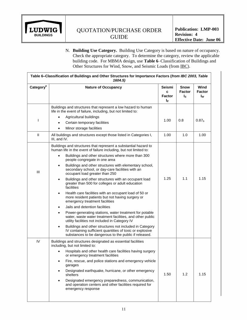
N. Building Use Category. Building Use Category is based on nature of occupancy.
Check the appropriate category. To determine the category, review the applicable
building code. For MBMA design, use Table 6–Classification of Buildings and
Other Structures for Wind, Snow, and Seismic Loads (from IBC).
Table 6–Classification of Buildings and Other Structures for Importance Factors (from IBC 2003, Table
1604.5)
Categorya Nature of Occupancy Seismi
c
Factor
IE
Snow
Factor
IS
Wind
Factor
IW
I
Buildings and structures that represent a low hazard to human life in the event of failure, including, but not limited to:
Agricultural buildings
Certain temporary facilities
Minor storage facilities
1.00
0.8
0.87b
II All buildings and structures except those listed in Categories I, III, and IV.
1.00 1.0 1.00
III
Buildings and structures that represent a substantial hazard to human life in the event of failure including, but not limited to:
Buildings and other structures where more than 300 people congregate in one area
Buildings and other structures with elementary school, secondary school, or day-care facilities with an occupant load greater than 250
Buildings and other structures with an occupant load greater than 500 for colleges or adult education facilities
Health care facilities with an occupant load of 50 or more resident patients but not having surgery or emergency treatment facilities
Jails and detention facilities
Power-generating stations, water treatment for potable water, waste water treatment facilities, and other public utility facilities not included in Category IV
Buildings and other structures not included in Category IV containing sufficient quantities of toxic or explosive substances to be dangerous to the public if released.
1.25
1.1
1.15
IV Buildings and structures designated as essential facilities including, but not limited to:
Hospitals and other health care facilities having surgery or emergency treatment facilities
Fire, rescue, and police stations and emergency vehicle garages
Designated earthquake, hurricane, or other emergency shelters
Designated emergency preparedness, communication, and operation centers and other facilities required for emergency response
1.50
1.2
1.15
QUOTATION/PURCHASE ORDER
GUIDE
Publication: LMP-003
Revision: 4
Effective Date: June 06
12
LUDWIG BUILDINGS
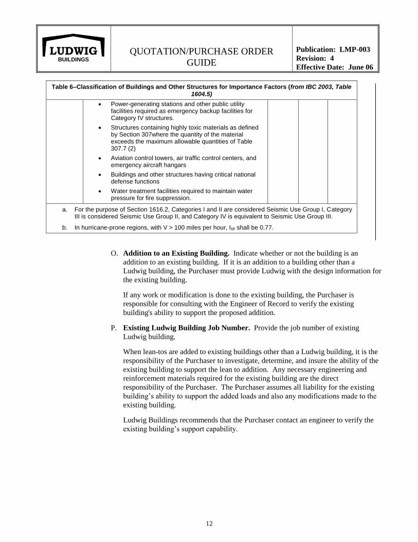
Table 6–Classification of Buildings and Other Structures for Importance Factors (from IBC 2003, Table
1604.5)
Power-generating stations and other public utility facilities required as emergency backup facilities for Category IV structures.
Structures containing highly toxic materials as defined by Section 307where the quantity of the material exceeds the maximum allowable quantities of Table 307.7 (2)
Aviation control towers, air traffic control centers, and emergency aircraft hangars
Buildings and other structures having critical national defense functions
Water treatment facilities required to maintain water pressure for fire suppression.
a. For the purpose of Section 1616.2, Categories I and II are considered Seismic Use Group I, Category III is considered Seismic Use Group II, and Category IV is equivalent to Seismic Use Group III.
b. In hurricane-prone regions, with V > 100 miles per hour, IW shall be 0.77.
O. Addition to an Existing Building. Indicate whether or not the building is an
addition to an existing building. If it is an addition to a building other than a
Ludwig building, the Purchaser must provide Ludwig with the design information for
the existing building.
If any work or modification is done to the existing building, the Purchaser is
responsible for consulting with the Engineer of Record to verify the existing
building's ability to support the proposed addition.
P. Existing Ludwig Building Job Number. Provide the job number of existing
Ludwig building.
When lean-tos are added to existing buildings other than a Ludwig building, it is the
responsibility of the Purchaser to investigate, determine, and insure the ability of the
existing building to support the lean to addition. Any necessary engineering and
reinforcement materials required for the existing building are the direct
responsibility of the Purchaser. The Purchaser assumes all liability for the existing
building’s ability to support the added loads and also any modifications made to the
existing building.
Ludwig Buildings recommends that the Purchaser contact an engineer to verify the
existing building’s support capability.
QUOTATION/PURCHASE ORDER
GUIDE
Publication: LMP-003
Revision: 5
Effective Date: Dec 06
13
LUDWIG BUILDINGS
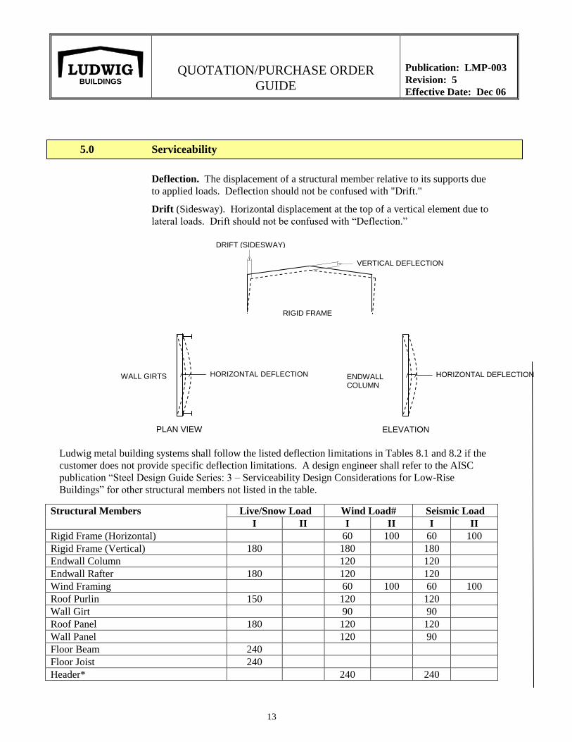
5.0 Serviceability
Deflection. The displacement of a structural member relative to its supports due
to applied loads. Deflection should not be confused with "Drift."
Drift (Sidesway). Horizontal displacement at the top of a vertical element due to
lateral loads. Drift should not be confused with “Deflection.”
Ludwig metal building systems shall follow the listed deflection limitations in Tables 8.1 and 8.2 if the
customer does not provide specific deflection limitations. A design engineer shall refer to the AISC
publication “Steel Design Guide Series: 3 – Serviceability Design Considerations for Low-Rise
Buildings” for other structural members not listed in the table.
Structural Members Live/Snow Load Wind Load# Seismic Load
I II I II I II
Rigid Frame (Horizontal) 60 100 60 100
Rigid Frame (Vertical) 180 180 180
Endwall Column 120 120
Endwall Rafter 180 120 120
Wind Framing 60 100 60 100
Roof Purlin 150 120 120
Wall Girt 90 90
Roof Panel 180 120 120
Wall Panel 120 90
Floor Beam 240
Floor Joist 240
Header* 240 240
ELEVATION
ENDWALL COLUMN
HORIZONTAL DEFLECTION
PLAN VIEW
WALL GIRTS HORIZONTAL DEFLECTION
VERTICAL DEFLECTION
DRIFT (SIDESWAY)
RIGID FRAME
QUOTATION/PURCHASE ORDER
GUIDE
Publication: LMP-003
Revision: 5
Effective Date: Dec 06
14
LUDWIG BUILDINGS
Notes: * Header that supports masonry wall.
# 10-year wind load.
I without brittle wall material.
II with brittle wall material.
Check if other deflection/serviceability requirements are needed due to types of
materials (e.g., masonry, glass, etc.) and describe on page 3 of the
Quotation/Purchase Order form.
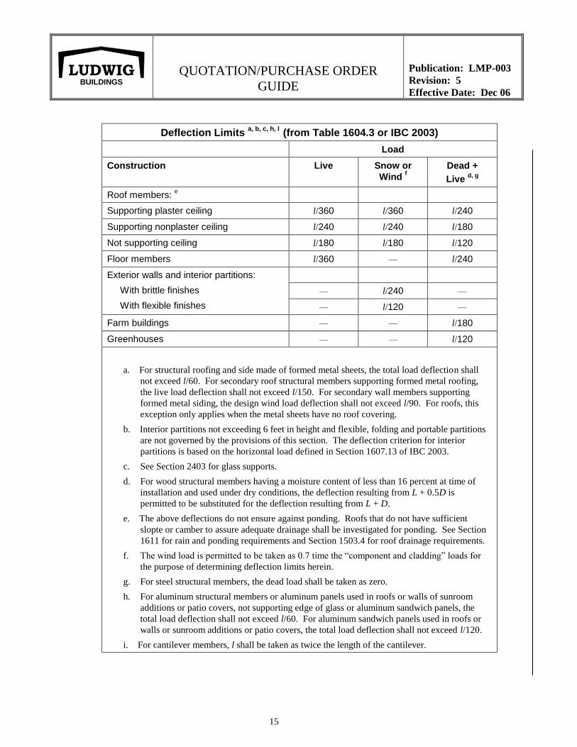
Table 1604.3 of IBC 2003 gives deflection limits for some special cases. If a building fits its
requirements, its deflection limits shall be adopted.
QUOTATION/PURCHASE ORDER
GUIDE
Publication: LMP-003
Revision: 5
Effective Date: Dec 06
15
LUDWIG BUILDINGS
Deflection Limits a, b, c, h, I
(from Table 1604.3 or IBC 2003)
Load
Construction Live Snow or
Wind f
Dead +
Live d, g
Roof members: e
Supporting plaster ceiling l/360 l/360 l/240
Supporting nonplaster ceiling l/240 l/240 l/180
Not supporting ceiling l/180 l/180 l/120
Floor members l/360 — l/240
Exterior walls and interior partitions:
With brittle finishes
With flexible finishes
— l/240 —
— l/120 —
Farm buildings — — l/180
Greenhouses — — l/120
a. For structural roofing and side made of formed metal sheets, the total load deflection shall
not exceed l/60. For secondary roof structural members supporting formed metal roofing,
the live load deflection shall not exceed l/150. For secondary wall members supporting
formed metal siding, the design wind load deflection shall not exceed l/90. For roofs, this
exception only applies when the metal sheets have no roof covering.
b. Interior partitions not exceeding 6 feet in height and flexible, folding and portable partitions
are not governed by the provisions of this section. The deflection criterion for interior
partitions is based on the horizontal load defined in Section 1607.13 of IBC 2003.
c. See Section 2403 for glass supports.
d. For wood structural members having a moisture content of less than 16 percent at time of
installation and used under dry conditions, the deflection resulting from L + 0.5D is
permitted to be substituted for the deflection resulting from L + D.
e. The above deflections do not ensure against ponding. Roofs that do not have sufficient
slopte or camber to assure adequate drainage shall be investigated for ponding. See Section
1611 for rain and ponding requirements and Section 1503.4 for roof drainage requirements.
f. The wind load is permitted to be taken as 0.7 time the “component and cladding” loads for
the purpose of determining deflection limits herein.
g. For steel structural members, the dead load shall be taken as zero.
h. For aluminum structural members or aluminum panels used in roofs or walls of sunroom
additions or patio covers, not supporting edge of glass or aluminum sandwich panels, the
total load deflection shall not exceed l/60. For aluminum sandwich panels used in roofs or
walls or sunroom additions or patio covers, the total load deflection shall not exceed l/120.
i. For cantilever members, l shall be taken as twice the length of the cantilever.
QUOTATION/PURCHASE ORDER
GUIDE
Publication: LMP-003
Revision: 1
Effective Date: Nov 99
16
LUDWIG BUILDINGS
6.0 Drawings
Indicate the type of drawings required by checking the appropriate box(es) from the
following choices. Drawings only represent those drawings pertaining to the Ludwig
building system and do not include any other type of project drawings (e.g., foundation,
electrical, etc.)
A. Anchor Bolt Plan. A plan view drawing showing the diameter, location, and
projection of all anchor bolts for the components of the Metal Building System
and may show column reactions (magnitude and direction). The maximum base
plate dimensions may also be shown.
B. Erection Drawings. Roof and wall erection (framing) drawings that identify
individual components and accessories furnished by the manufacturer in
sufficient detail to permit proper erection of the Metal Building System.
C. Permit Drawings. Drawings used strictly for permitting of the metal building
only. These drawings are NOT for construction.
D. Approval Drawings. A set of drawings that may include framing plans,
elevations, and sections through the building for approval of the buyer. These
drawings are NOT for construction.
E. Letter of Certification. A letter provided by Ludwig's engineers confirming
that the design of the metal building system is in accordance with the code and
design loads that are specified on the Ludwig Quotation/Purchase Order.

QUOTATION/PURCHASE ORDER
GUIDE
Publication: LMP-003
Revision: 1
Effective Date: Nov 99
17
LUDWIG BUILDINGS
BASIC BUILDING INFORMATION
7.0 Building Information
A. Building ____ of _____. If only one building is requested for this quote/order,
indicate Building 1 of 1. If additional buildings are requested for this quote, indicate
the building number of the total buildings for the quote/order (e.g., building 1 of 4).
Describe additional buildings and lean-tos on an Additional Buildings Sheet or on
another Quotation/Purchase Order.
B. Building Type.
Indicate the building type using the following abbreviations. If the type is not
included here, spell out (for example, T-canopy, mini-storage, etc.). Ludwig
standard types available are:
RF Gable type
SS Single slope type
LT Lean-to type
M-1, M-2 Multi-span (Modular Frame)
M-3, etc.
NOTE: Modular multi-span frames are designated as M-1, M-2, M-3, etc.
indicating the number of interior support columns. Therefore, M-1 has one interior
support column, M-2 has two interior support columns, etc.
QUOTATION/PURCHASE ORDER
GUIDE
Publication: LMP-003
Revision: 1
Effective Date: Nov 99
18
LUDWIG BUILDINGS
C. Frame Profile.
Ludwig's standard frame profile is:
TC/BG Tapered Column/Bypass Girts
Other profiles available are:
TC/FG Tapered Column/Flush Girts
SC/BG Straight Column/Bypass Girts
SC/FG Straight Column/Flush Girts
If the profiles other than indicated are required, please note them on the Building
Layout Sheet. Normally, TC/BG (tapered column/bypass girts) is the most
economical. In some cases, Ludwig's Engineering Department will use SC/BG
versus TC/BG if more economical.
D. Width. The dimension of the building measured parallel to the main framing from
sidewall to sidewall girts.
Indicate the building width in feet and inches. If girts are not used, explain building
width on the Building Layout Sheet.
E. Length. The dimension of the building measured perpendicular to the main framing
from endwall to endwall girts.
Indicate the building length. If girts are not used, explain length on the Building
Layout Sheet.
F. Eave Height. The vertical dimension from finished floor to the top of the eave strut.
Indicate the eave height in feet and inches.
G. Roof Slope. The tangent of the angle that a roof surface makes with the horizontal,
usually expressed in units of vertical rise to 12 units of horizontal run.
Indicate the roof slope (e.g., 2:12, which means that for every 12 inches of horizontal
run, the roof will rise vertically by 2 inches).
H. Sidewall Bay Spacing. A bay is the space between the main frames measured
normal to the frame.
Indicate the bay spacing in the sidewalls from left to right. Measure spacing from
interior centerline to centerline of the interior sidewall columns. For the end bay
spacing, measure from the outside of the endwall girt to the centerline of the first
interior sidewall column.
QUOTATION/PURCHASE ORDER
GUIDE
Publication: LMP-003
Revision: 1
Effective Date: Nov 99
19
LUDWIG BUILDINGS
I. Interior Modular Column Spacing. For modular frames, indicate the column
spacing of the interior columns. Modular column spacing is measured from the
centerline of each interior modular column, except at the sidewalls, which are
measured from outside girt to the centerline of the first interior modular column.
8.0 Girts
A Girt is a horizontal structural member that is attached to sidewall or endwall columns
and support paneling.
Flush Girt. Girts that are mounted where the outside flange of the girts and columns are
flush.
Bypass Girt. Girts that are mounted on the outside of the columns.
Indicate if girts are to be flush or bypass at any of the walls. Ludwig's standard is bypass
girts, which are the most economical. If no boxes are marked, girts will be bypass.
9.0 End Frames
An End Frame is a frame located at the endwall of a building that supports the loads
from a portion of the end bay.
Indicate end frame type from the following types. Note that support material that is not
supplied by Ludwig must be capable of supporting building loads.
A. Non-expandable: Non-expandable end frames do not allow expansion of building
length and are the most economical design. Diagonal bracing requirements may
restrict location of openings.
B. Expandable rigid frame: Expandable rigid end frames allow for the expansion of
building length in the future if the expansion is consistent with the current building’s
design criteria.
C. Non-expandable rigid frame: Non-expandable rigid frames are designed for half-
bay loading and do not allow for building length expansion.
D. Shelf-angle: A structural angle used to support roof purlins and attached to a
structure or materials such as masonry, tilt-up, or metal studs not by Ludwig.
Materials used to support this shelf angle must be designed to support the roof and
design loads.
E. No Frame: When No Frame is selected, Ludwig does not provide an endwall frame,
purlins are supported by other materials supplied by the Purchaser, and a description
of those materials must be included in notes. Materials used to support the purlins
must be designed to support the roof and design loads.
QUOTATION/PURCHASE ORDER
GUIDE
Publication: LMP-003
Revision: 1
Effective Date: Nov 99
20
LUDWIG BUILDINGS
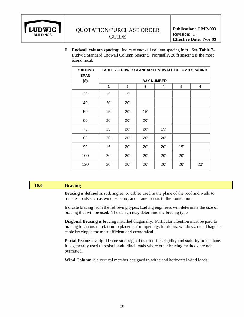
F. Endwall column spacing: Indicate endwall column spacing in ft. See Table 7–
Ludwig Standard Endwall Column Spacing. Normally, 20 ft spacing is the most
economical.
BUILDING
SPAN
TABLE 7–LUDWIG STANDARD ENDWALL COLUMN SPACING
(ft) BAY NUMBER
1 2 3 4 5 6
30 15' 15'
40 20' 20'
50 15' 20' 15'
60 20' 20' 20'
70 15' 20' 20' 15'
80 20' 20' 20' 20'
90 15' 20' 20' 20' 15'
100 20' 20' 20' 20' 20'
120 20' 20' 20' 20' 20' 20'
10.0 Bracing
Bracing is defined as rod, angles, or cables used in the plane of the roof and walls to
transfer loads such as wind, seismic, and crane thrusts to the foundation.
Indicate bracing from the following types. Ludwig engineers will determine the size of
bracing that will be used. The design may determine the bracing type.
Diagonal Bracing is bracing installed diagonally. Particular attention must be paid to
bracing locations in relation to placement of openings for doors, windows, etc. Diagonal
cable bracing is the most efficient and economical.
Portal Frame is a rigid frame so designed that it offers rigidity and stability in its plane.
It is generally used to resist longitudinal loads where other bracing methods are not
permitted.
Wind Column is a vertical member designed to withstand horizontal wind loads.
QUOTATION/PURCHASE ORDER
GUIDE
Publication: LMP-003
Revision: 1
Effective Date: Nov 99
21
LUDWIG BUILDINGS
11.0 Attached Sheets
List all additional Ludwig form sheets required for proper design for the building (for
example, Ludwig Building Layout Sheet, Ludwig Crane Data Sheet, Ludwig Mezzanine
Data Sheet, Ludwig Point Loads Sheet, and/or Ludwig Additional Buildings Sheet). By
doing so, information contained in those sheets will become a part of this contract. Any
additional information not included on Ludwig form sheets, must be noted on page 3 of
the Ludwig Quotation/ Purchase Order.
QUOTATION/PURCHASE ORDER
GUIDE
Publication: LMP-003
Revision: 1
Effective Date: Nov 99
A-1
LUDWIG BUILDINGS
APPENDIX A - GLOSSARY OF METAL BUILDING TERMS
QUOTATION/PURCHASE ORDER
GUIDE
Publication: LMP-003
Revision: 1
Effective Date: Nov 99
A-2
LUDWIG BUILDINGS
Glossary of Metal Building Systems Terms2
Accessory – A building product that supplements a basic solid panel building such as a door, window, skylight, ventilator, etc.
Agricultural Building – A structure designed and constructed to house farm implements, hay, grain, poultry, livestock or other
horticultural products. Such structure shall not include habitable spaces, spaces in which agricultural products are processed, treated or
packaged; nor shall an agricultural building be a place of occupancy by the general public.
Aluminum Coated Steel – Steel coated with aluminum for corrosion resistance.
Anchor Bolts – Bolts used to anchor members to a foundation or other support.
Anchor Bolt Plan – A plan view drawing showing the diameter, location and projection of all anchor bolts for the components of the
Metal Building System and may show column reactions (magnitude and direction). The maximum base plate dimensions may also be
shown.
Approval Drawings – A set of drawings that may include framing plans, elevations and sections through the building for approval of the
buyer.
ASD – Allowable Stress Design.
Assembly – A group of mutually dependent and compatible components or subassemblies of components.
Astragal – A closure between the two leaves of a double swing or double slide door.
Automatic Crane – A crane which when activated operates through a pre-set cycle or cycles.
Automatic Welding – A welding procedure utilizing a machine to make a weld.
Auxiliary Crane Girder – A girder arranged parallel to the main girder for supporting the platform, motor base, operator's cab, control
panels, etc., to reduce the torsional forces that such load would otherwise impose on the main crane girder.
Auxiliary Hoist – A supplemental hoisting unit, usually designed to handle lighter loads at a higher speed than the main crane hoist.
Auxiliary Loads – Dynamic live loads such as those induced by cranes and material handling systems.
Axial Force – A force tending to elongate or shorten a member.
Bar Joist – A name commonly used for "Open Web Steel Joists."
Base Angle – An angle secured to a wall or foundation used to attach the bottom of the wall paneling.
Base Plate – A plate attached to the bottom of a column which rests on a foundation or other support, usually secured by anchor bolts.
Base Tube – A continuous member imbedded in the edge of the foundation to which the wall panels are attached.
Bay – The space between the main frames measured normal to the frame.
Beam – A member, usually horizontal, that is subjected to bending loads. There are three types, simple, continuous, and cantilever.
Beam and Column – A structural system consisting of a series of rafter beams supported by columns, often used as the end frame of a
building.
Bearing End Frame – See "Beam and Column."
2 From Metal Building Manufacturer’s Association (MBMA) Low Rise Building Systems Manual. 1996.
QUOTATION/PURCHASE ORDER
GUIDE
Publication: LMP-003
Revision: 1
Effective Date: Nov 99
A-3
LUDWIG BUILDINGS
Bearing Plate – A steel plate that is set on the top of a masonry support on which a beam or purlin can rest.
Bent – See "Main Frame."
Bill of Materials – A list that enumerates by part number or description each piece of material or assembly to be shipped. Also called tally
sheet or shipping list.
Bird Screen – Wire mesh used to prevent birds from entering the building through ventilators and louvers.
Blind Rivet – A small headed pin with expandable shank for joining light gage metal. Typically used to attach flashing, gutter, etc.
Box Girder – Girders, trucks or other members of rectangular cross section enclosed on four sides.
Bracing – Rods, angles or cables used in the plane of the roof and walls to transfer loads, such as wind, seismic and crane thrusts to the
foundation.
Bracket – A structural support projecting to a structural member. Examples are canopy brackets, lean-to brackets, and crane runway
brackets.
Bridge (Crane) – That part of an overhead crane consisting of girders, trucks, end ties, walkway and drive mechanism which carries the
trolley and travels in a direction parallel to the runway.
Bridge Crane – A load lifting system consisting of a hoist which moves laterally on a beam, girder or bridge which in turn moves
longitudinally on a runway made of beams and rails.
Bridging – Bracing or systems of bracing used between structural members.
British Thermal Unit (BTU) – That amount of heat required to raise the temperature of one pound of water by 1 F.
Builder – See "Dealer."
Building – A structure forming an open, partially enclosed, or enclosed space constructed by a planned process of combining materials,
components, and subsystems to meet specific conditions of use.
Building Aisle – A space defined by the length of the building and the space between building columns.
Building Code – Regulations established by a recognized agency describing design loads, procedures and construction details for
structures usually applying to a designated political jurisdiction (city, county, state, etc.).
Built-Up Roofing – A roof covering made up of alternating layers of tar and asphaltic materials.
Built-Up Section – A structural member, usually an I-shaped section, made from individual flat plates welded together.
Bumper – An energy-absorbing device for reducing impact when a moving crane or trolley reaches the end of its permitted travel; or when
two moving cranes or trolleys come into contact.
Butt Plate – The end plate of a structural member usually used to rest against a like plate of another member in forming a connection.
Sometimes called a splice plate or bolted end plate.
Bypass Girt – See "Exterior Framed."
"C" Section – A member formed from steel sheet in the shape of a block "C" that may be used either singularly or back to back.
Cab-Operated Crane – A crane controlled by an operator in a cab supported on the bridge or trolley.
Camber – Curvature of a flexural member in the plane of its web before loading.
Canopy – A projecting roof system that is supported and restrained at one end only.
Cantilever Beam – A beam supported only at one end having a free end and a fixed end.
QUOTATION/PURCHASE ORDER
GUIDE
Publication: LMP-003
Revision: 1
Effective Date: Nov 99
A-4
LUDWIG BUILDINGS
Capillary Action – That action which causes movement of liquids when in contact with two adjacent surfaces such as panel sidelaps.
Cap Plate – A plate located at the top of a column or end of a beam for capping the exposed end of the member.
Capacity – The maximum load (usually stated in tons) which a crane is designed to support.
Caulk – See "Sealant."
Channel, Hot Rolled – A C-shaped member formed while in a semi-molten state at the steel mill to a shape having standard dimensions
and properties.
Cladding – The exterior metal roof and wall paneling of a Metal Building System. See also "Components and Cladding."
Clip – A plate or angle used to fasten two or more members together.
Closure Strip – A resilient strip, formed to the contour of ribbed panels and used to close openings created by ribbed panels joining other
components.
Cold Forming – The process of using press brakes or rolling mills to shape steel into desired cross sections at room temperature.
Collateral Loads – The weight of additional permanent materials required by the contract, other than the Building System, such as
sprinklers, mechanical and electrical systems, partitions and ceilings.
Column – A main member used in a vertical position on a building to transfer loads from main roof beams, trusses, or rafters to the
foundation.
Component – A part used in a Metal Building System. See also "Components and Cladding."
Components and Cladding – For wind load considerations, members that do not qualify as part of a Main Wind Force Resisting System.
They include girts, joists, purlins, studs, wall and roof panels, fasteners, endwall columns and endwall rafters of bearing end frames, roof
overhang beams, canopy beams, and masonry walls when acting as other than shear walls.
Concealed Clip – A hold down clip used with a wall or roof panel system to connect the panel to the supporting structure without
exposing the fasteners on the exterior surface.
Connection – The means of attachment of one structural member to another.
Continuity – The terminology given to a structural system denoting the transfer of loads and stresses from member to member as if there
were no connections.
Continuous Beam – A beam having three or more supports.
Contract Documents – The Documents that define the material and work to be provided by a Contractor or the General Contractor for a
Construction Project.
Covering – See "Cladding."
Crane – A machine designed to move material by means of a hoist.
Crane Aisle – That portion of a building aisle in which a crane operates, defined by the crane span and the uninterrupted length of crane
runway.
Crane Girder – The principal horizontal beams of the crane bridge which supports the trolley and is supported by the end tracks.
Crane Rail – A track supporting and guiding the wheels of a bridge crane or trolley system. On underhung cranes, the crane rail also acts
as the runway beam.
Crane Runway Beam – The member that supports a crane rail and is supported by columns or rafters depending on the type of crane
system. On underhung bridge cranes, the runway beam also acts as the crane rail.
QUOTATION/PURCHASE ORDER
GUIDE
Publication: LMP-003
Revision: 1
Effective Date: Nov 99
A-5
LUDWIG BUILDINGS
Crane Span – The horizontal distance center-to-center of runway beams.
Crane Stop – A device to limit travel of a trolley or crane bridge. This device normally is attached to a fixed structure and normally does
not have energy-absorbing ability.
Crane Support Column – A separate column which supports the runway beam of a top-running crane.
Curb – A raised edge on a concrete floor slab or roof accessory.
Curtain Wall – Perimeter wall panels which carry only their own weight and wind load.
Damper – A baffle used to open or close the throat of ventilators.
Dead Load – The weight of the Building System construction consisting of members such as framing and covering.
Dealer – A party who, as a routine part of his business, buys Metal Building Systems from a manufacturer for the purpose of resale.
Deflection – The displacement of a structural member relative to its supports due to applied loads. Deflection should not be confused with
"Drift."
Design Loads – The loads expressly specified in the contract documents that the Metal Building System is designed to safely resist.
Design Professional – The Architect or Engineer responsible for the design of a Construction Project.
Diagonal Bracing – See "Bracing."
Diaphragm Action – The resistance to racking generally offered by the panels, fasteners, and members to which they are attached.
Direct Tension Indicator – See "Load Indicating Washer."
Door Guide – An angle or channel used to stabilize or keep plumb a sliding or rolling door during its operation.
Downspout – A conduit used to carry water from the gutter of a building.
Drift (Sidesway) – Horizontal displacement at the top of a vertical element due to lateral loads. Drift should not be confused with
"Deflection."
Drift (Snow) – The snow accumulation at a height discontinuity.
Drift Pin – A tapered pin used during erection to align holes in steel members to be connected by bolting.
Eave – The line along the sidewall formed by the intersection of the planes of the roof and wall.
Eave Gutter – See "Gutter."
Eave Height – The vertical dimension from finished floor to the eave.
Eave Strut – A structural member located at the eave of a building that supports roof and wall paneling.
Edge Strip – The surface area of a building at the edges of the roof and at the wall intersections where the wind loads on components and
cladding are greater than at other areas of the building.
Effective Wind Area – The area used to determine the wind coefficient. The effective wind area may be greater than or equal to the
tributary area.
Elastic Design – A design concept utilizing the proportional behavior of materials when all stresses are limited to specified allowable
values in the elastic range.
Electric Operated Crane – A crane in which the bridge, hoist or trolley is operated by electric power.
QUOTATION/PURCHASE ORDER
GUIDE
Publication: LMP-003
Revision: 1
Effective Date: Nov 99
A-6
LUDWIG BUILDINGS
Electric Overhead Traveling Crane – An electrically-operated machine for lifting, lowering and transporting loads, consisting of a
movable bridge carrying a fixed or movable hoisting mechanism and traveling on an overhead runway structure.
End Approach – The minimum horizontal distance, parallel to the runway, between the outermost extremities of the crane and the
centerline of the hook.
End Bay – The bays adjacent to the endwalls of a building. Usually the distance from the endwall to the first interior main frame measured
normal to the endwall.
End Frame – A frame located at the endwall of a building which supports the loads from a portion of the end bay.
End Post – See "Endwall Column."
End Stop – A device attached to a crane runway or rail to provide a safety stop at the end of a runway.
End Truck – The unit consisting of truck frame, wheels, bearings, axles, etc., which supports the bridge girders.
Endwall – An exterior wall that is parallel to the interior main frame of the building.
Endwall Column – A vertical member located at the endwall of a building that supports the girts. In beam and column end frames,
endwall columns also support the beam.
Endwall Overhang – The projection of the roof beyond the plane of the endwall.
End Zone – The surface area of a building along the roof at the endwall and at the corners of walls.
Engineer/Architect of Record – The engineer or architect who is responsible for the overall design of the building project. The
manufacturer’s engineer is typically not the Engineer of Record.
Erection – The on-site assembling of fabricated Metal Building System components to form a completed structure.
Erection Bracing – Materials used by erectors to stabilize the building system during erection.
Erection Drawings – Roof and wall erection (framing) drawings that identify individual components and accessories furnished by the
manufacturer in sufficient detail to permit proper erection of the Metal Building System.
Erector – A party who assembles or erects a Metal Building System.
Expansion Joint – A break or space in construction to allow for thermal expansion and contraction of the materials used in the structure.
Exterior Framed – A wall framing system where the girts are mounted on the outside of the columns.
Fabrication – The manufacturing process performed in a plant to convert raw material into finished Metal Building System components.
The main operations are cold forming, cutting, punching, welding, cleaning and painting.
Facade – An architectural treatment, partially covering a wall, usually concealing the eave and/or the rake of the building.
Fascia – A decorative trim or panel projecting from the face of a wall.
Field – The "job site," "building site," or general marketing area.
Filler Strip – See "Closure Strip."
Film Laminated Coil – Coil metal that has a corrosion resistant film laminated to it prior to the forming operation.
Fixed Clip – A standing seam roof system hold down clip which does not allow the roof panel to move independently of the roof
substructure.
Fixed Base – A column base that is designed to resist rotation as well as horizontal or vertical movement.
QUOTATION/PURCHASE ORDER
GUIDE
Publication: LMP-003
Revision: 1
Effective Date: Nov 99
A-7
LUDWIG BUILDINGS
Flange – The projecting edge of a structural member.
Flange Brace – A member used to provide lateral support to the flange of a structural member.
Flashing – see "Trim."
Floating Clip – See "Sliding Clip."
Floor Live Load – Those loads induced on the floor system by the use and occupancy of the building.
Flush Frames – A wall framing system where the outside flange of the girts and the columns are flush.
Footing – A pad or mat, usually of concrete, located under a column, wall or other structural member, that is used to distribute the loads
from that member into the supporting soil.
Foundation – The substructure which supports a building or other structure.
Framed Opening – Framing members and flashing which surround an opening.
Framing Plans – See "Erection Drawings."
Gable – The triangular portion of the endwall from the level of the eave to the ridge of the roof.
Gable Overhang – See "Endwall Overhang."
Gable Roof – A roof consisting of two sloping sides that form a ridge and a gable at each.
Galvanized – Steel coated with zinc for corrosion resistance.
Gantry Crane – A crane similar to an overhead crane except that the bridge for carrying the trolley or trolleys is rigidly supported on one
or more legs running on fixed rails or other runway.
Girder – A main horizontal or near horizontal structural member that supports vertical loads. It may consist of several pieces.
Girt – A horizontal structural member that is attached to sidewall or endwall columns and supports paneling.
Glaze – The process of installing glass in windows and doors.
Glazing – Glass panes or paneling used in windows and doors.
Grade – The term used when referring to the ground elevation around a building.
Grade Beam – A concrete beam around the perimeter of a building.
Ground Snow Load – The probable weight of snow on the ground for a specified recurrence interval exclusive of drifts or sliding snow.
Grout – A mixture of cement, sand and water used to fill cracks and cavities. Sometimes used under base plates or leveling plates to obtain
uniform bearing surfaces.
Gusset Plate – A steel plate used to reinforce or connect structural elements.
Gutter – A light gauge metal member at an eave, valley or parapet designed to carry water from the roof to downspouts or drains.
"H" Section – A steel member with a cross section in the shape of an "H."
Hair Pin – "V" shaped reinforcing steel used to transfer anchor bolt shear to the concrete floor mass.
Hand-Geared (Crane) – A crane in which the bridge, hoist, or trolley is operated by the manual use of chain and gear without electric
power.
QUOTATION/PURCHASE ORDER
GUIDE
Publication: LMP-003
Revision: 1
Effective Date: Nov 99
A-8
LUDWIG BUILDINGS
Haunch – The deepened portion of a column or rafter designed to accommodate the higher bending moments at such points. (Usually
occurs at the intersection of column and rafter.)
Haunch Brace – A diagonal member from the intersection of the column and rafter section of the rigid frame to the eave member to
prevent lateral buckling of the haunch.
Header – The horizontal framing member located at the top of a framed opening.
High Strength Bolts – Any bolt made from steel having a tensile strength in excess of 100,000 pounds per square inch.
High Strength Steel – Structural steel having a yield stress in excess of 36,000 pounds per square inch.
Hinged Base – See "Pinned Base."
Hip – The line formed at the intersection of two adjacent sloping planes of a roof.
Hip Roof – A roof that is formed by sloping planes from all four sides.
Hoist – A mechanical lifting device usually attached to a trolley that travels along a bridge, monorail or jib crane. May be chain or electric
operated.
Horizontal Guide Rollers – Wheels mounted near the ends of end trucks that roll on the side of the rail to restrict lateral movement of the
crane.
Hot-Rolled Shapes – Steel sections (angles, channels, S-shapes, W-shapes, etc.) which are formed by rolling mills while the steel is in a
semi-molten state.
"I" Beam – See "S" Shape.
Ice Dam – A buildup of ice which forms a dam on the roof covering along the eave of the building.
Impact Load – A dynamic load resulting from the motion of machinery, elevators, craneways, vehicles, and other similar moving forces.
See Auxiliary Loads.
Impact Wrench – A power tool used to tighten nuts on bolts.
Importance Factor – A factor that accounts for the degree of hazard to human life and damage to property.
Insulation – Any material used in building construction to reduce heat transfer.
Internal Pressure – Pressure inside a building.
Jack Beam – A beam used to support another beam, rafter or truss and eliminate a column support.
Jack Truss – A truss used to support another beam, rafter or truss and eliminate a column support.
Jamb – The vertical framing members located at the sides of an opening.
Jib Crane – A cantilevered or suspended beam with hoist and trolley. This lifting device may pick up loads in all or part of a circle around
the column to which it is attached.
Jig – A device used to hold pieces of material in a certain position during fabrication.
Joist – Light beam for supporting a floor or roof.
Kick-Out (Elbow) (Turn-Out) – An extension attached to the bottom of a downspout to direct water away from a wall.
Kip – A unit of measure equal to 1,000 pounds.
Knee – The connecting area of a column and rafter of a structural frame such as a rigid frame.
QUOTATION/PURCHASE ORDER
GUIDE
Publication: LMP-003
Revision: 1
Effective Date: Nov 99
A-9
LUDWIG BUILDINGS
Knee Brace – A diagonal member at a column and rafter intersection designed to resist horizontal loads.
Lean-To – A structure having only one slope and depending upon another structure for partial support.
Length – The dimension of the building measured perpendicular to the main framing from endwall to endwall.
Leveling Plate – A steel plate used on top of a foundation or other support on which a structural column can rest.
Lift (Crane) – Maximum safe vertical distance through which the hook, magnet, or bucket can move.
Lifting Devices (Crane) – Buckets, magnets, grabs and other supplemental devices, the weight of which is to be considered part of the
rated load, used for ease in handling certain types of loads.
Liner Panel – A metal panel attached to the inside flange of the girts or inside of a wall panel.
Live Load – See "Roof or Floor Live Load."
Load Indicating Washers – A washer with dimples which flatten when the high strength bolt is tightened. The bolt tension can then be
determined by the use of feeler gages to determine the gap between the washer and the bolt head.
Longitudinal – The direction parallel to the ridge or sidewall.
Longitudinal (Crane) – Direction parallel to the crane runway beams.
Louver – An opening provided with fixed or movable, slanted fins to allow flow of air.
Low Rise Building – A description of a class of buildings usually less than 60' eave height. Commonly, they are single story, but do not
exceed 4 stories.
LRFD – Load and Resistance Factor Design.
Main Frame – An assemblage of rafters and columns that support the secondary framing members and transfer loads directly to the
foundation.
Main Wind Force Resisting System – A structural assembly which provides for the overall stability of the building and receives wind
loads from more than one surface. Examples include shear walls, diaphragms, rigid frames, and space structures.
Manufacturer – A party who designs and fabricates a Metal Building System.
Manufacturer's Engineer – An engineer employed by a manufacturer who is in responsible charge of the structural design of a Metal
Building System fabricated by the manufacturer. The manufacturer’s engineer is typically not the Engineer of Record.
Masonry – Anything constructed of materials such as bricks, concrete blocks, ceramic blocks, and concrete.
Mastic – See "Sealant."
Mean Roof Height – Average height of roof above ground.
Metal Building System – A complete integrated set of mutually dependent components and assemblies that form a building including
primary and secondary framing, covering and accessories, and are manufactured to permit inspection on site prior to assembly or erection.
Mezzanine – An intermediate level between floor and ceiling occupying a partial area of the floor space.
Mill Duty Crane – Cranes with service classification E and F as defined by CMAA.
Moment – The tendency of a force to cause rotation about a point or axis.
Moment Connection – A connection designed to transfer moment as well as axial and shear forces between connecting members.
Moment of Inertia – A physical property of a member, which helps define strength and deflection characteristics.
QUOTATION/PURCHASE ORDER
GUIDE
Publication: LMP-003
Revision: 1
Effective Date: Nov 99
A-10
LUDWIG BUILDINGS
Monolithic Construction – A method of placing concrete grade beam and floor slab together to form the building foundation without
forming and placing each separately.
Monorail Crane – A crane that travels on a single runway beam, usually a "S" or "W" beam.
Multi-Gable Building – Buildings consisting of more than one gable across the width of the building.
Multi-Span Building – Buildings consisting of more than one span across the width of the building. Multiple gable buildings and single
gable buildings with interior columns are examples.
Multiple Girder Crane – A crane which has two or more girders for supporting the lifted load.
Oil Canning – A waviness that may occur in flat areas of light gage, formed metal products. Structural integrity is not normally affected by
this inherent characteristic and therefore is only an aesthetic issue.
Open Web Steel Joists – Light weight truss.
Order Documents – The documents normally required by the Manufacturer in the ordinary course of entering and processing an order.
Outrigger – See "Auxiliary Crane Girder."
Overhanging Beam – A simply supported beam that extends beyond its support.
Overhead Doors – See "Sectional Overhead Doors."
Panels – See "Cladding."
Panel Notch – A notch or block out formed along the outside edge of the floor slab to provide support for the wall panels and serve as a
closure along their bottom edge.
Pan Panel – A standing seam panel which has vertical sides and has no space between the panels at the side laps.
Parapet – That portion of the vertical wall of a building which extends above the roof line.
Parts and Portions – See "Components and Cladding."
Peak – The uppermost point of a gable.
Peak Sign – A sign attached to the peak of the building at the endwall showing the building manufacturer.
Pendant-Operated Crane – Crane operated from a pendant control unit suspended from the crane.
Personnel Doors – A door used by personnel for access to and exit from a building.
Piece Mark – A number given to each separate part of the building for erection identification. Also called mark number and part number.
Pier – A concrete structure designed to transfer vertical load from the base of a column to the footing.
Pig Spout – A sheet metal section designed to direct the flow of water out through the face of the gutter rather than through a downspout.
Pilaster – A reinforced or enlarged portion of a masonry wall to provide support for roof loads or lateral loads on the wall.
Pinned Base – A column base that is designed to resist horizontal and vertical movement, but not rotation.
Pin Connection – A connection designed to transfer axial and shear forces between connecting members, but not moments.
Pitch – The peak height of a gabled building divided by its overall span.
Plastic Design – A design concept based on multiplying the actual loads by a suitable load factor, and using the yield stress as the
maximum stress in any member, and taking into consideration moment redistribution.
QUOTATION/PURCHASE ORDER
GUIDE
Publication: LMP-003
Revision: 1
Effective Date: Nov 99
A-11
LUDWIG BUILDINGS
Plastic Panels – See "Translucent Light Panels."
Ponding – 1) The gathering of water at low or irregular areas on a roof. 2) Progressive accumulation of water from deflection due to rain
loads.
Pop Rivet – See "Blind Rivet."
Porosity – Openings in buildings which allow air to enter during a wind storm.
Portal Frame – A rigid frame so designed that it offers rigidity and stability in its plane. It is generally used to resist longitudinal loads
where other bracing methods are not permitted.
Post – See "Column."
Post and Beam – See "Beam and Column."
Posttensioning – A method of prestressing reinforced concrete in which tendons are tensioned after the concrete has reached a specific
strength.
Power Actuated Fastener – A device for fastening items by the utilization of a patented device which uses an explosive charge or
compressed air to embed the pin in the concrete or steel.
Pretensioning – A method of prestressing reinforced concrete in which the tendons are tensioned before the concrete has been placed.
Pre-Painted Coil – Coil of metal which has received a paint coating.
Press Brake – A machine used in cold-forming metal sheet or strip into desired sections.
Prestressed Concrete – Concrete in which internal stresses of such magnitude and distribution are introduced that the tensile stresses
resulting from the service loads are counteracted to a desired degree; in reinforced concrete the prestress is commonly introduced by
tensioning the tendons.
Primary Framing – See "Main Frame."
Prismatic Beam – A beam with uniform cross section.
Public Assembly – A building or space where 300 or more persons may congregate in one area.
Purlin – A horizontal structural member which supports roof covering.
Rafter – The main beam supporting the roof system.
Rail (Crane) – See "Crane Rail."
Rails (Door) – The horizontal stiffening members of framed and paneled doors.
Rake – The intersection of the plane of the roof and the plane of the endwall.
Rake Angle – Angle fastened to purlins at rake for attachment of endwall panels.
Rake Trim – A flashing designed to close the opening between the roof and endwall panels.
Rated Capacity (Crane) – The maximum load (usually in tons) which the crane is designed to support safely.
Reactions – The resisting forces at the column bases holding the structure in equilibrium under a given loading condition.
Reinforcing Steel – The steel placed in concrete as required to carry the tension, compression and shear stresses.
Remote-Operated Crane – A crane controlled by an operator not in a pulpit or in the cab attached to the crane, by any method other than
pendant or rope control.
QUOTATION/PURCHASE ORDER
GUIDE
Publication: LMP-003
Revision: 1
Effective Date: Nov 99
A-12
LUDWIG BUILDINGS
Retrofit – The placing of new metal roof or wall systems over deteriorated roofs or walls.
Rib – The longitudinal raised profile of a panel that provides much of the panel’s bending strength.
Ribbed Panel – A panel which has ribs with sloping sides and forms a trapezoidal shaped void at the side lap.
Ridge – The horizontal line formed by opposing sloping sides of a roof running parallel with the building length.
Ridge Cap – A transition of the roofing materials along the ridge of a roof; sometimes called ridge roll or ridge flashing.
Rigid Connection – See "Moment Connection."
Rigid Frame – A structural frame consisting of members joined together with moment connections so as to render the frame stable with
respect to the design loads, without the need for bracing in its plane.
Rolling Doors – Doors that are supported at the bottom on wheels which run on a track.
Roll-up Door – A door that opens by traveling vertically.
Roof Covering – The exposed exterior roof surface consisting of panels.
Roof Live Load – Loads that are produced (1) during maintenance by workers, equipment, and materials, and (2) during the life of the
structure by movable objects and do not include wind, snow, seismic or dead loads.
Roof Overhang – A roof extension beyond the endwall or sidewall of a building.
Roof Slope – The tangent of the angle that a roof surface makes with the horizontal, usually expressed in units of vertical rise to 12 units of
horizontal run.
Roof Snow Load – That load induced by the weight of snow on the roof of the structure. Usually obtained by taking a fraction of the
"Ground Snow Load."
Ropeseal – See "Sealant."
Runway Beam – See "Crane Runway Beam."
Runway Bracket – A bracket attached to the column of a building frame which supports the runway beam for top-running cranes.
Runway Conductors – The main conductors mounted on or parallel to the runway that supplies electric current to the crane.
"S" Shape – A hot rolled beam with narrow tapered flanges.
Sag Member – A tension member such as rods, straps or angles used to limit the deflection of a girt or purlin in the direction of its weak
axis.
Sandwich Panel – A panel used as covering consisting of an insulating core material with inner and outer metal skins.
Screwed Down Roof System – See "Through-Fastened Roof System."
Scupper – An opening in a gutter or parapet system that prevents ponding.
Sealant – Any material that is used to seal cracks, joints or laps.
Secondary Framing – Members which carry loads from the building surface to the main framing. For example - purlins and girts.
Seaming Machine – A mechanical device that is used to close and seal the side seams of standing seam roof panels.
Section Modulus – A geometric property of a structural member. It is used in design to determine the flexural strength of a member.
QUOTATION/PURCHASE ORDER
GUIDE
Publication: LMP-003
Revision: 1
Effective Date: Nov 99
A-13
LUDWIG BUILDINGS
Sectional Overhead Doors – Doors constructed in horizontally hinged sections. They are equipped with springs, tracks, counter balancers,
and other hardware that roll the sections into an overhead position, clear of the opening.
Seismic Load – The lateral load acting in any horizontal direction on a structural system due to the action of an earthquake.
Self Drilling Screw – A fastener which combines the functions of drilling and tapping.
Self Tapping Screw – A fastener which taps its own threads in a predrilled hole.
Seller – A party who sells a Metal Building System with or without its erection or other field work.
Shear – The force tending to make two contacting parts slide upon each other in opposite directions parallel to their plane of contact.
Shear Diaphragm – See "Diaphragm."
Shim – A piece of steel used to level base plates or align columns or beams.
Shipping List – See "Bill of Materials."
Shop Primer Paint – The initial coat of primer paint applied in the shop.
Shot Pin – See "Power Actuated Fastener."
Side Lap Fastener – A fastener used to connect panels together at their side lap.
Sidesway – See "Drift (Sidesway)."
Sidewall – An exterior wall that is perpendicular to the frames of a building system.
Sidewall Overhang – See "Roof Overhang."
Sill – The bottom horizontal framing member of a wall opening such as a window or door.
Simple Connection – See "Pin Connection."
Simple Span – A term used in structural design to describe a beam support condition at two points which offers no resistance to rotation at
the supports.
Single Slope – A sloping roof in one plane. The slope is from one wall to the opposite wall.
Single Span - - A building or structural member without intermediate support.
Siphon Break – A small groove to arrest the capillary action of two adjacent surfaces. (Anti-Capillary Groove).
Sister Column – See "Crane Support Column."
Skylight – A roof accessory to admit light, normally mounted on a curbed framed opening.
Slide Door – A single or double leaf door which opens horizontally by means of sliding on an overhead trolley.
Sliding Clip – A standing seam roof system hold down clip which allows the roof panel to move independently of the roof substructure.
Slope – See "Roof Slope."
Snow Drift – See "Drift (Snow)."
Snow Load – See "Roof Snow Load."
Snug Tight – The tightness of a bolt in a connection that exists when all plies in a joint are in firm contact.
QUOTATION/PURCHASE ORDER
GUIDE
Publication: LMP-003
Revision: 1
Effective Date: Nov 99
A-14
LUDWIG BUILDINGS
Soffit – A material which covers the underside of an overhang.
Soil Pressure – The load per unit area a structure will exert through its foundation on the soil.
Soldier Column – An intermediate column used to support secondary structurals; not part of a main frame or beam and column system.
Spacer Strut (Crane) – A type of assembly used to keep the end trucks of adjacent cranes on the same runway beams a minimum specified
distance apart.
Span – The distance between supports of beams, girders, or trusses.
Specification (Metal Building System) – A statement of a set of Metal Building System requirements describing the loading conditions,
design practices, materials and finishes.
Splice – A connection in a structural member.
Spud Wrench – A tool used by erectors to line up holes and to make up bolted connections; a wrench with a tapered handle.
Square – The term used for an area of 100 square feet.
Stainless Steel – An alloy of steel which contains a high percentage of chromium to increase corrosion resistance. Also may contain nickel
or copper.
Standing Seam – Side joints of roof panels that are arranged in a vertical position above the roof line.
Standing Seam Roof System – A standing seam roof system is one in which the side laps between the roof panels are arranged in a
vertical position above the roof line. The roof panel system is secured to the roof substructure by means of concealed hold down clips
attached with screws to the substructure, except that through fasteners may be used at limited locations such as at ends of panels and at roof
penetrations.
Stiffener – A member used to strengthen a plate against lateral or local buckling. Usually a flat bar welded perpendicular to the
longitudinal axis of the member.
Stiffener Lip – A short extension of material at an angle to the flange of cold formed structural members, which adds strength to the
member.
Stiles – The vertical side members of framed and paneled doors.
Stitch Screw – A fastener connecting panels together at the sidelap.
Straight Tread Wheels – Crane wheels with flat machined treads and double flanges that limit the lateral movement of the crane.
Strain – The deformation per unit length measured in the direction of the stress caused by forces acting on a member. Not the same as
deflection.
Stress – A measure of the load on a structural member in terms of force per unit area.
Strut – A member fitted into a framework which resists axial compressive forces.
Stud – A vertical wall member to which exterior or interior covering or collateral material may be attached. May be either load bearing or
non-load bearing.
Suspension System – The system (rigid or flexible) used to suspend the runway beams of underhung or monorail cranes from the rafter of
the building frames.
Sweep – The amount of deviation of straightness of a structural section measured perpendicular to the web of the member.
Tapered Members – A built up plate member consisting of flanges welded to a variable depth web.
QUOTATION/PURCHASE ORDER
GUIDE
Publication: LMP-003
Revision: 1
Effective Date: Nov 99
A-15
LUDWIG BUILDINGS
Tapered Tread Wheels – End truck wheels with treads that are tapered, the large diameter being toward the center of the span.
Tensile Strength – The longitudinal pulling stress a material can bear without tearing apart.
Tension Forces – Forces acting on a member tending to elongate it.
Thermal Block – A spacer of low thermal conductance material.
Thermal Conductance, (C-factor) – The time rate of heat flow through unit area of a body induced by unit temperature difference
between the body surfaces. Units are Btu / (hour x ft2 x F) [Imperial system] or Watts / (m2 x C) [SI system]. See "Thermal resistance."
Thermal Conductivity, (k-factor) – The time rate of heat flow through unit thickness of a flat slab of a homogenous material in the
perpendicular direction to the slab surfaces induced by unit temperature gradient. Units for k are (Btu x in) / (hour x ft2 x F) or Btu / (hour
x ft x F) [Imperial system] and Watts / (m x C) [SI system]. See "Thermal resistivity."
Thermal Resistance (R-value) – Under steady conditions, the mean temperature difference between two defined surfaces of material or
construction that induces unit heat flow through unit area. Note: Thermal resistance and thermal conductance are reciprocals. Thermal
resistances are R-values; to obtain the U-factor, overall thermal transmittance, the R-value for either materials or constructions must first be
evaluated because, by definition, the U-factor is the reciprocal of the sum of the individual R-values.
Thermal Resistivity – Under steady conditions, the temperature difference between parallel surfaces of a slab (large enough so there is no
lateral heat flow) of unit thickness that induces unit heat flow through unit area. Note: Thermal resistivity and thermal conductivity are
reciprocals. Thermal resistivity is the R-value of a material of unit thickness.
Thermal Transmittance (U-factor) – The time rate of heat flow per unit area under steady conditions from the fluid on the warm side of a
barrier to the fluid on the cold side, per unit temperature difference between the two fluids. It is evaluated by first evaluating the R-value
and then computing its reciprocal.
Through-Fastened Roof System – A through-fastened roof system is one in which the roof panels are attached directly to the roof
substructure with fasteners which penetrate through the roof sheets and into the substructure.
Through Ties – Reinforcing steel, usually in the concrete, extending from one column pier to the other column pier, tying the two columns
of a rigid frame together to resist thrust.
Thrust – The horizontal component of a reaction usually at the column base.
Tie – A structural member that is loaded in tension.
Ton – 2,000 pounds.
Track – A metal way for wheeled components; specifically, one or more lines of ways, with fastenings, ties, etc., for a craneway, monorail
or slide door.
Translucent Light Panels – Panels used to admit light.
Transverse – The direction parallel to the main frames.
Tributary Area – The area directly supported by the structural member between contiguous supports.
Trim – The light gage metal used in the finish of a building, especially around openings and at intersections of surfaces. Often referred to
as flashing.
Trolley (Crane) – The unit carrying the hoisting mechanism.
Trolley Frame (Crane) – The basic structure of the trolley on which are mounted the hoisting and traversing mechanisms.
Truss – A structure made up of three or more members, with each member designed to carry a tension or compression force. The entire
structure in turn acts as a beam.
QUOTATION/PURCHASE ORDER
GUIDE
Publication: LMP-003
Revision: 1
Effective Date: Nov 99
A-16
LUDWIG BUILDINGS
Turnout – See "Kick-Out."
Turn-of-the-Nut Method – A method for pre-tensioning high strength bolts. The nut is turned from the "Snug tight" position,
corresponding to a few blows of an impact wrench or the full effort of a man using an ordinary spud wrench, the amount of rotation
required being a function of the bolt diameter and length.
Twist Off Bolts – Bolts with a segment which shears off at a predetermined torque during bolt tightening. These bolts utilize a specially
designed wrench for proper installation.
Uplift – Wind load on a building which causes a load in the upward direction.
Valley Gutter – A channel used to carry off water from the "V" of roofs of multi-gabled buildings.
Vapor Barrier – Material used to retard the flow of vapor or moisture to prevent condensation from forming on a surface.
Ventilator – An accessory, usually used on the roof, that allows the air to pass through.
"W" Shape – A hot rolled member with parallel flanges.
Wainscot – Wall material, used in the lower portion of a wall, that is different from the material in the rest of the wall.
Walk Door – See "Personnel Door."
Wall Covering – The exterior wall surface consisting of panels.
Web – That portion of a structural member between the flanges.
Web Stiffener – See "Stiffener."
Wheel Base – Distance from center-to-center of outermost crane wheels.
Wheel Load – The vertical force without impact produced on a crane wheel bearing on a runway rail or suspended from a runway beam.
Maximum wheel load occurs with the crane at rated capacity and the trolley positioned to provide maximum vertical force at one set of
wheels.
Width – The dimension of the building measured parallel to the main framing from sidewall to sidewall.
Wind Bent – See "Portal Frame."
Wind Column – A vertical member designed to withstand horizontal wind loads.
Wind Load – The load caused by the wind from any horizontal direction.
X-Bracing – Bracing system with members arranged diagonally in both directions to form an "X." See "Bracing."
"Z" Section – A member cold formed from steel sheet in the shape of a "Z."
Zinc-Aluminum Coated – Steel coated with an alloy of zinc and aluminum to provide corrosion resistance.
QUOTATION/PURCHASE ORDER
GUIDE
Publication: LMP-003
Revision: 5
Effective Date: Dec 06
B-1
LUDWIG BUILDINGS
APPENDIX B – WIND, SNOW, AND RAIN DATA: Reference the International
Code Council’s (ICC’s) International Building Code (IBC) 2006, Sections 1608, 1609, and 1611.
QUOTATION/PURCHASE ORDER
GUIDE
Publication: LMP-003
Revision: 5
Effective Date: Dec 06
C-1
LUDWIG BUILDINGS
APPENDIX C – SEISMIC DATA: Reference ICC’s International Building Code
(IBC) 2006, section 16.13.3.5 Site classification for seismic design, section 1613.5.5.1 Steps for classifying a site, and Figures 1613.5(1 – 14).
D-1
Appendix D –
Current Order Form and Example of Existing Building Input Window