Embed Size (px)
Citation preview
Quiz #4
What is the difference between random access and scheduling?
1
2
Note 6: Medium Access Control Protocols
Random Access
3
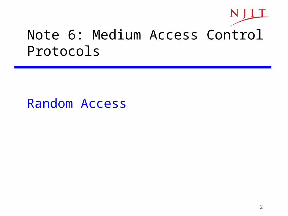
ALOHA• Wireless link to provide data transfer between main campus
& remote campuses of University of Hawaii • Simplest solution: just do it
– A station transmits whenever it has data to transmit– If more than one frames are transmitted, they interfere with each other
(collide) and are lost – If ACK not received within timeout, then a station picks random backoff
time (to avoid repeated collision)– Station retransmits frame after backoff time
tt0t0-X t0+X t0+X+2tprop
t0+X+2tprop + B
Vulnerableperiod
Time-out
Backoff period BFirst transmission Retransmission
4
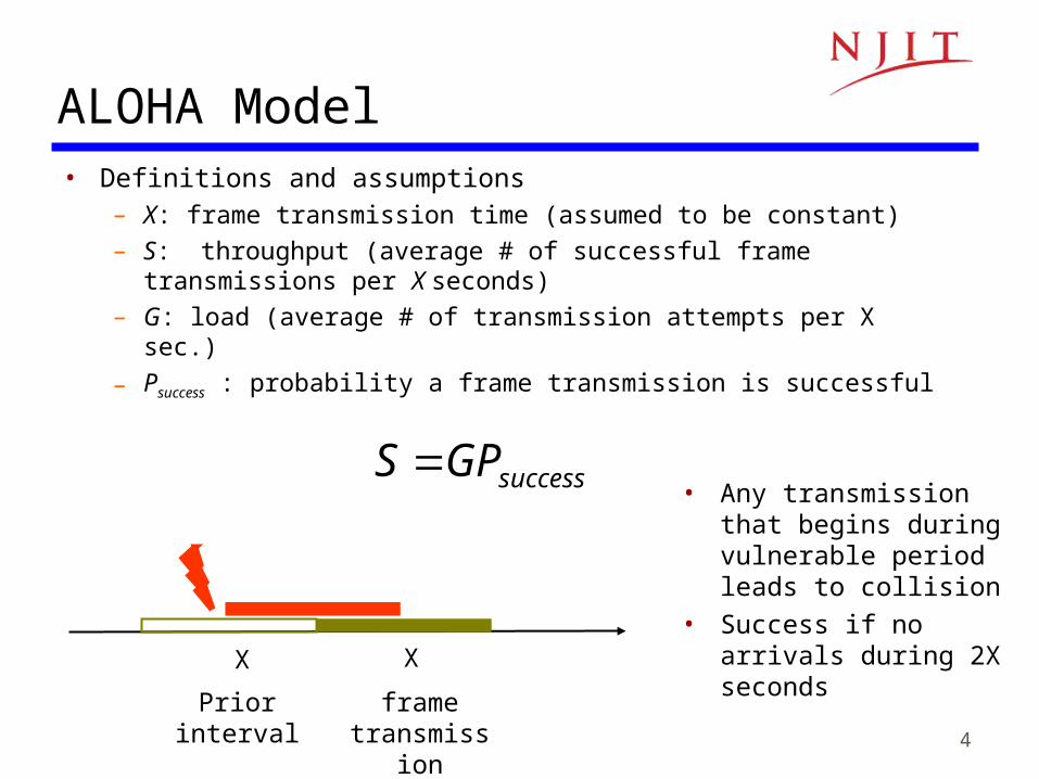
ALOHA Model• Definitions and assumptions
– X: frame transmission time (assumed to be constant)
– S: throughput (average # of successful frame transmissions per X seconds)
– G: load (average # of transmission attempts per X sec.)
– Psuccess : probability a frame transmission is successful
successGPS
XX
frame transmission
Prior interval
• Any transmission that begins during vulnerable period leads to collision
• Success if no arrivals during 2X seconds
5
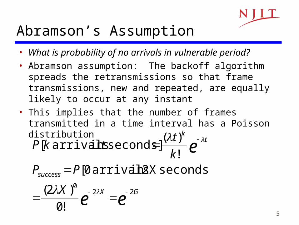
Abramson’s Assumption• What is probability of no arrivals in vulnerable period?• Abramson assumption: The backoff algorithm spreads
the retransmissions so that frame transmissions, new and repeated, are equally likely to occur at any instant
• This implies that the number of frames transmitted in a time interval has a Poisson distribution
ee
e
GX
success
tk
X
PPk
ttkP
220
!0
)2(
seconds] 2Xin arrivals 0[!
)(seconds] in arrivals [
6
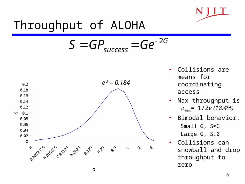
Throughput of ALOHAG
success GeGPS 2
00.020.040.060.080.1
0.120.140.160.180.2
G
S
• Collisions are means for coordinating access
• Max throughput is max=1/2e (18.4%)
• Bimodal behavior:Small G, S≈G
Large G, S↓0
• Collisions can snowball and drop throughput to zero
e-2 = 0.184

7
Slotted ALOHA• Time is slotted in X seconds slots • Stations synchronized to frame times• Stations transmit frames in first slot after frame arrival• Backoff intervals in multiples of slots
t(k+1)XkX t0 +X+2tprop+ B
Vulnerableperiod
Time-out
Backoff period B
t0 +X+2tprop
Only frames that arrive during prior X seconds collide
8
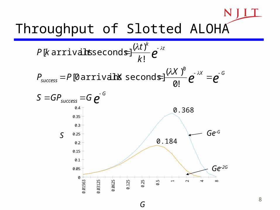
Throughput of Slotted ALOHA
0
0.05
0.1
0.15
0.2
0.25
0.3
0.35
0.4
0.01
563
0.03
125
0.06
25
0.12
5
0.25 0.5 1 2 4 8
Ge-G
Ge-2G
G
S0.184
0.368e
ee
e
G
success
GX
success
tk
GGPS
XPP
k
ttkP
!0
)(seconds] Xin arrivals 0[
!
)(seconds] in arrivals [
0
9
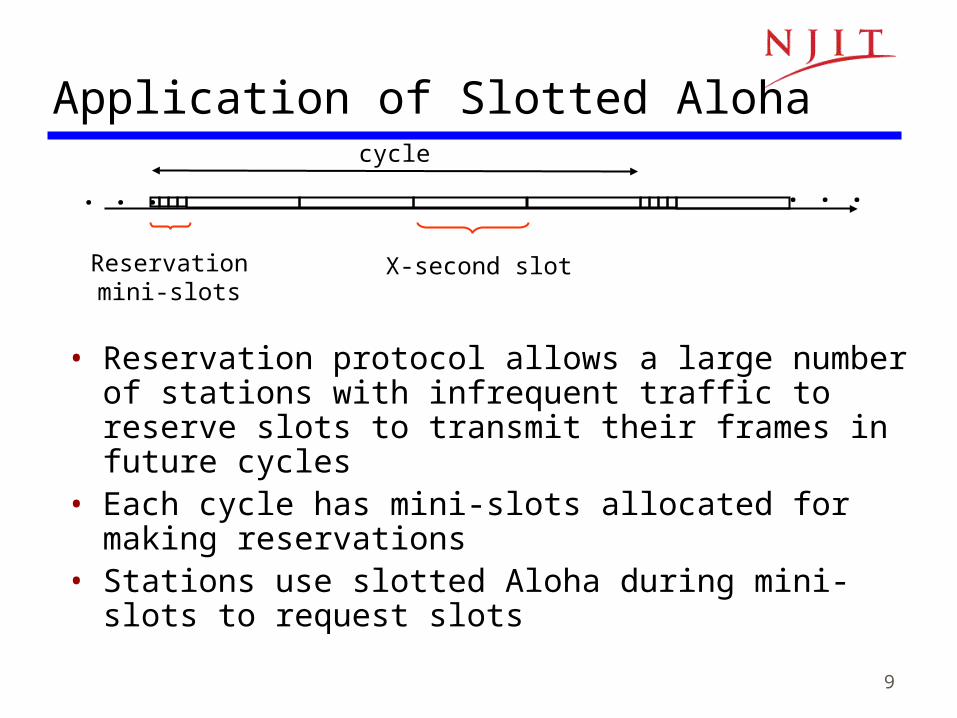
Application of Slotted Aloha
• Reservation protocol allows a large number of stations with infrequent traffic to reserve slots to transmit their frames in future cycles
• Each cycle has mini-slots allocated for making reservations
• Stations use slotted Aloha during mini-slots to request slots
cycle
X-second slotReservation mini-slots
. . .. . .
10
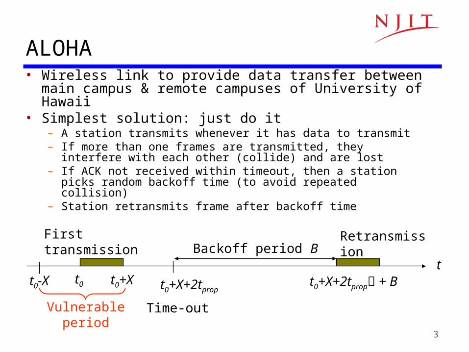
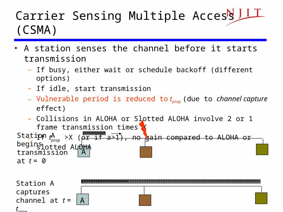
Carrier Sensing Multiple Access (CSMA)
A
Station A begins transmission at t = 0
A
Station A captureschannel at t = tprop
• A station senses the channel before it starts transmission– If busy, either wait or schedule backoff (different options)
– If idle, start transmission
– Vulnerable period is reduced to tprop (due to channel capture effect)
– Collisions in ALOHA or Slotted ALOHA involve 2 or 1 frame transmission times X
– If tprop >X (or if a>1), no gain compared to ALOHA or slotted ALOHA
11
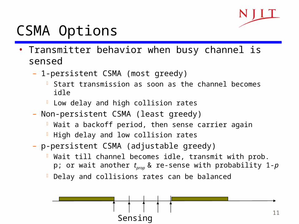
• Transmitter behavior when busy channel is sensed– 1-persistent CSMA (most greedy)
Start transmission as soon as the channel becomes idle Low delay and high collision rates
– Non-persistent CSMA (least greedy) Wait a backoff period, then sense carrier again High delay and low collision rates
– p-persistent CSMA (adjustable greedy) Wait till channel becomes idle, transmit with prob. p; or wait another
tprop & re-sense with probability 1-p Delay and collisions rates can be balanced
CSMA Options
Sensing
12
0
0.1
0.2
0.3
0.4
0.5
0.6
0.02
0.03
0.06
0.13
0.25 0.5 1 2 4 8 16 32 64
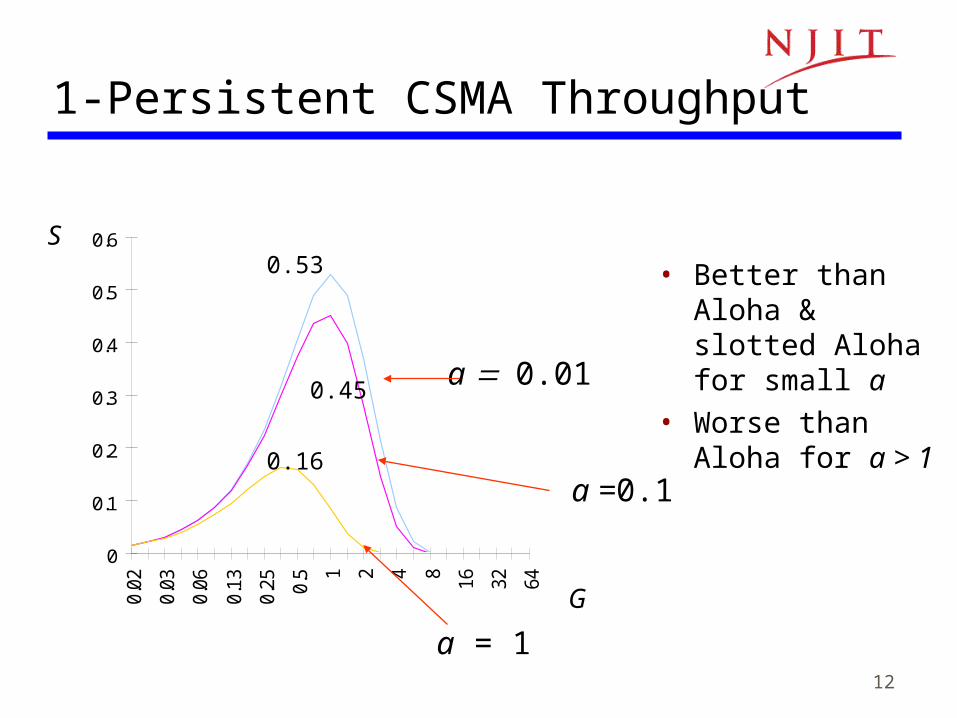
0.53
0.45
0.16
S
G
a 0.01
a =0.1
a = 1
1-Persistent CSMA Throughput
• Better than Aloha & slotted Aloha for small a
• Worse than Aloha for a > 1
13
0
0.1
0.2
0.3
0.4
0.5
0.6
0.7
0.8
0.9
0.02
0.03
0.06
0.13
0.25 0.5 1 2 4 8 16 32 64
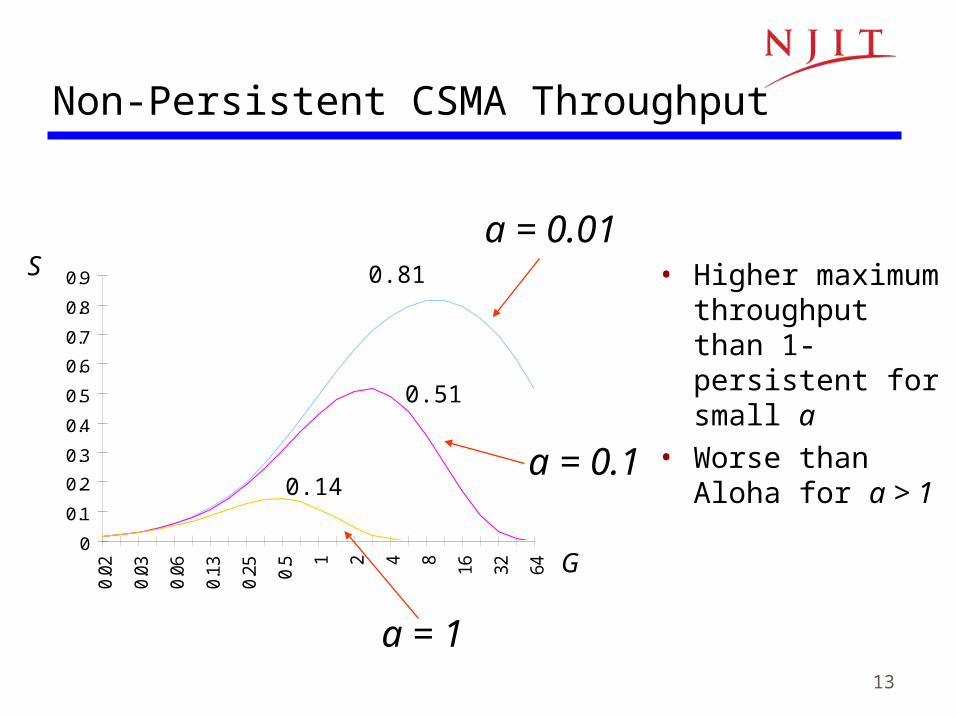
0.81
0.51
0.14
S
G
a = 0.01
Non-Persistent CSMA Throughput
a = 0.1
a = 1
• Higher maximum throughput than 1-persistent for small a
• Worse than Aloha for a > 1
14
CSMA with Collision Detection (CSMA/CD)
• Monitor for collisions & abort transmission– Stations with frames to send, first do carrier sensing
– After beginning transmissions, stations continue listening to the medium to detect collisions
– If collisions detected, all stations involved stop transmission, reschedule random backoff times, and try again at scheduled times
• In CSMA collisions result in wastage of X seconds spent transmitting an entire frame
• CSMA-CD reduces wastage to time to detect collision and abort transmission
15
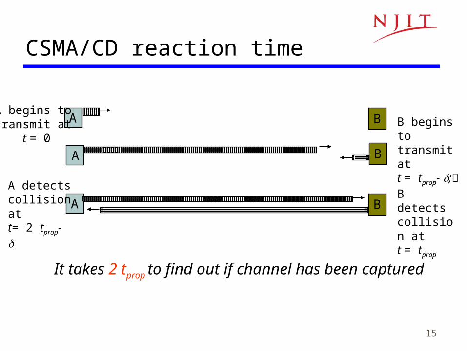
CSMA/CD reaction time
It takes 2 tprop to find out if channel has been captured
A begins to transmit at
t = 0
A B B begins to transmit at t = tprop- ;B detectscollision at t = tprop
A B
A B
A detectscollision at t= 2 tprop-
16
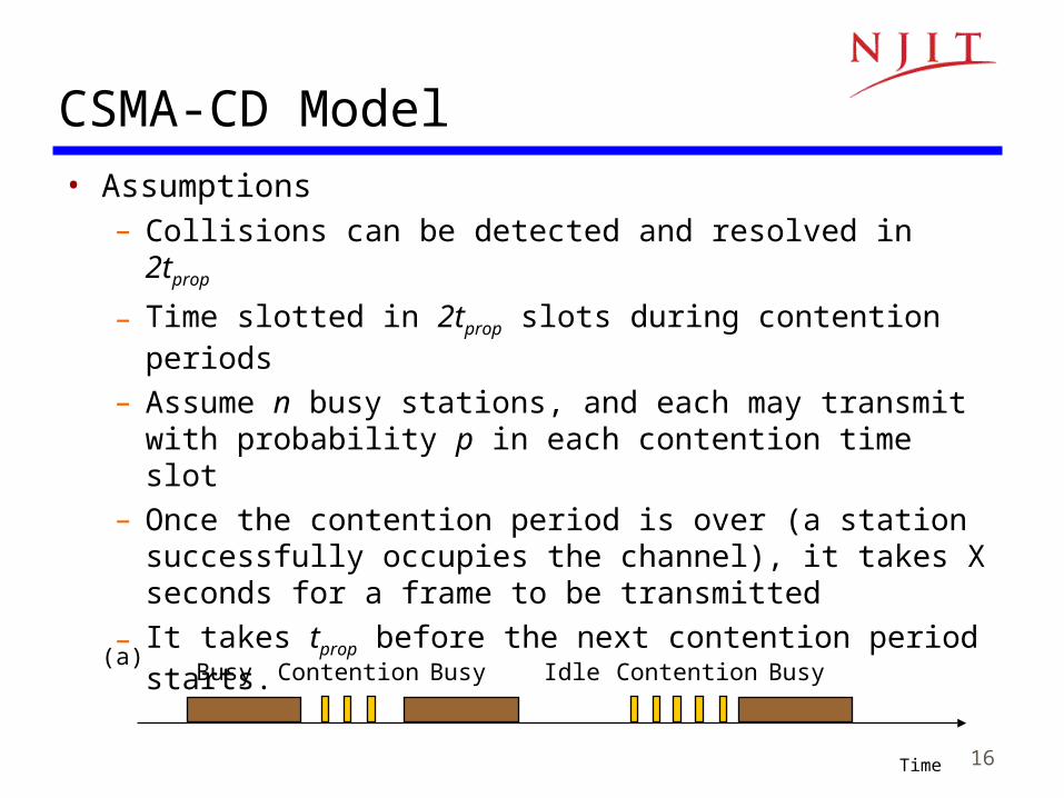
CSMA-CD Model• Assumptions
– Collisions can be detected and resolved in 2tprop
– Time slotted in 2tprop slots during contention periods
– Assume n busy stations, and each may transmit with probability p in each contention time slot
– Once the contention period is over (a station successfully occupies the channel), it takes X seconds for a frame to be transmitted
– It takes tprop before the next contention period starts.
Busy Contention Busy(a)
Time
Idle Contention Busy
17
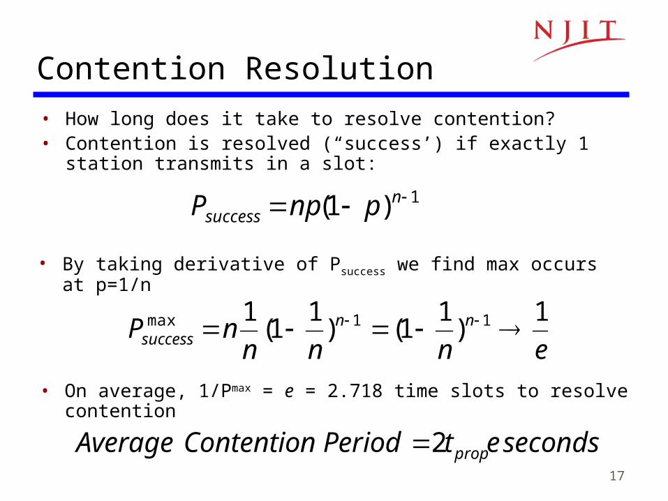
Contention Resolution• How long does it take to resolve contention?• Contention is resolved (“success’) if exactly 1 station transmits in a
slot:
1)1( nsuccess pnpP
• By taking derivative of Psuccess we find max occurs at p=1/n
ennnnP nn
success
1)
11()
11(
1 11max
• On average, 1/Pmax = e = 2.718 time slots to resolve contention
secondsPeriod Contention Average 2 et prop
18
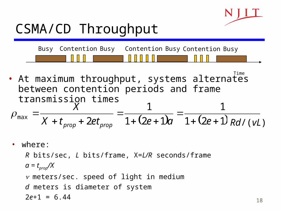
CSMA/CD Throughput
• At maximum throughput, systems alternates between contention periods and frame transmission times
LRdeaeettX
X
propprop /121
1
121
1
2max
Time
Busy Contention Busy Contention Busy Contention Busy
• where:R bits/sec, L bits/frame, X=L/R seconds/frame
a = tprop/X
meters/sec. speed of light in medium
d meters is diameter of system
2e+1 = 6.44
Rd/(vL)
19
CSMA-CD Application: Ethernet
• First Ethernet LAN standard used CSMA-CD– 1-persistent Carrier Sensing– R = 10 Mbps
– tprop = 51.2 microseconds 512 bits = 64 byte slot accommodates 2.5 km + 4 repeaters
– Truncated Binary Exponential Backoff After the nth collision, select backoff from {0, 1,…, 2k – 1},
where k=min(n, 10)
20
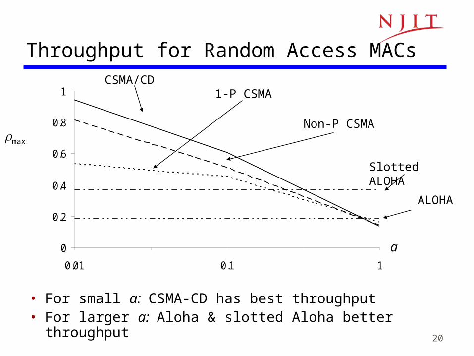
Throughput for Random Access MACs
0
0.2
0.4
0.6
0.8
1
0.01 0.1 1
ALOHA
Slotted ALOHA
1-P CSMA
Non-P CSMA
CSMA/CD
a
max
• For small a: CSMA-CD has best throughput• For larger a: Aloha & slotted Aloha better throughput
21
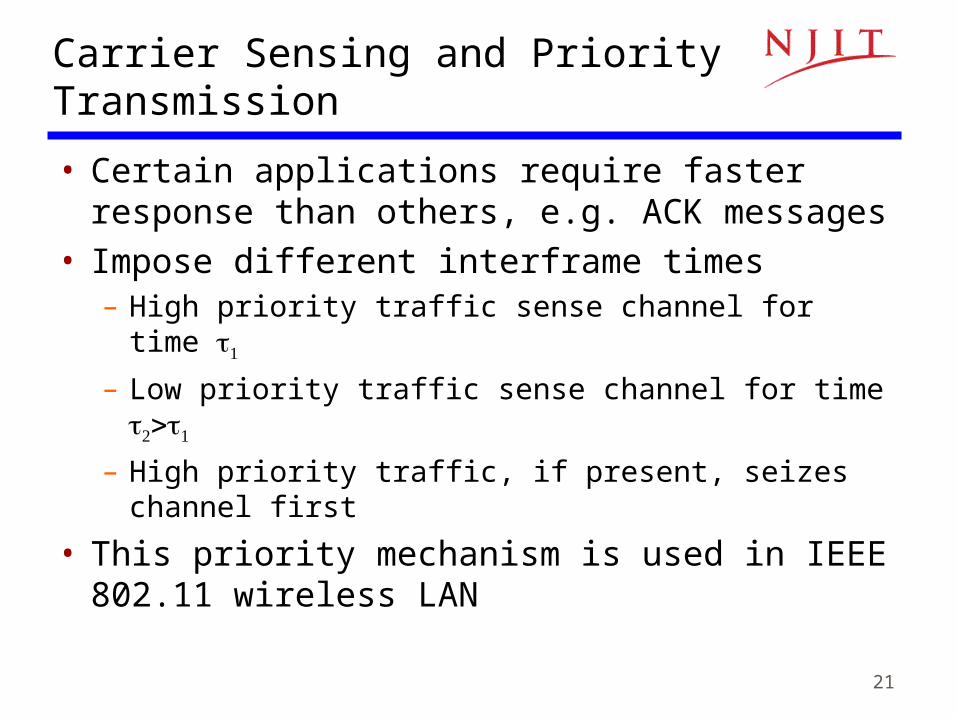
Carrier Sensing and Priority Transmission
• Certain applications require faster response than others, e.g. ACK messages
• Impose different interframe times– High priority traffic sense channel for time
– Low priority traffic sense channel for time
– High priority traffic, if present, seizes channel first
• This priority mechanism is used in IEEE 802.11 wireless LAN
22
Note 6: Medium Access Control Protocols
Scheduling
23
Scheduling for Medium Access Control
• Schedule frame transmissions to avoid collision in shared mediumMore efficient channel utilizationLess variability in delaysCan provide fairness to stations Increased computational or procedural complexity
• Two main approaches– Reservation– Polling
24
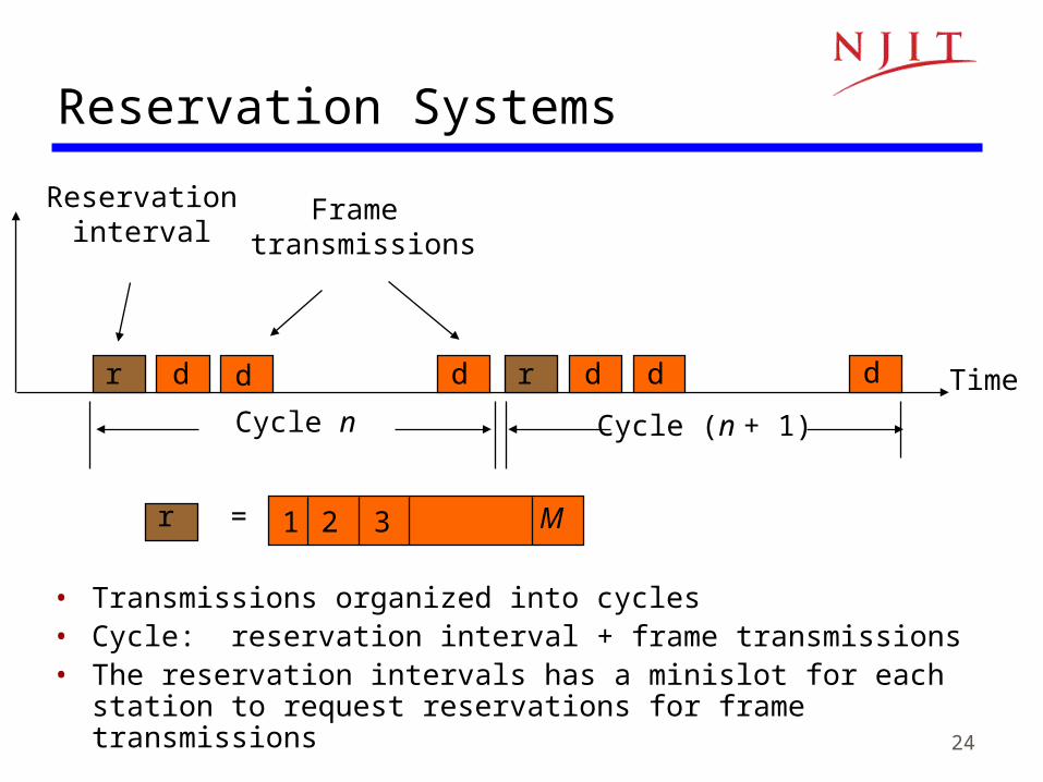
Reservation Systems
Time
Cycle n
Reservationinterval
Frame transmissions
r d d d r d d d
Cycle (n + 1)
r = 1 2 3 M
• Transmissions organized into cycles• Cycle: reservation interval + frame transmissions• The reservation intervals has a minislot for each station to request
reservations for frame transmissions
25
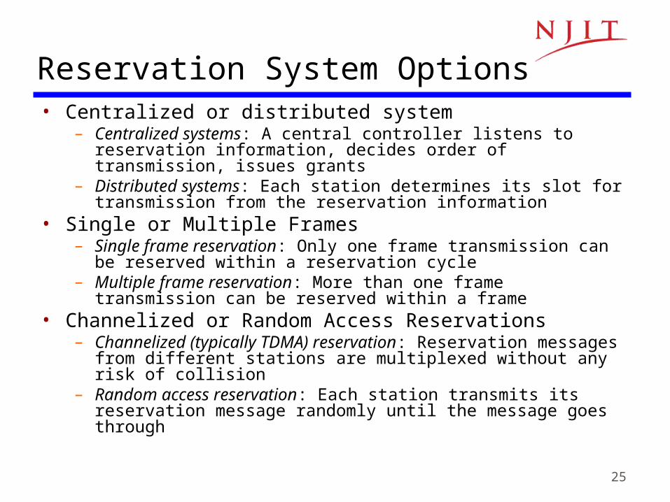
Reservation System Options• Centralized or distributed system
– Centralized systems: A central controller listens to reservation information, decides order of transmission, issues grants
– Distributed systems: Each station determines its slot for transmission from the reservation information
• Single or Multiple Frames– Single frame reservation: Only one frame transmission can be reserved
within a reservation cycle– Multiple frame reservation: More than one frame transmission can be
reserved within a frame• Channelized or Random Access Reservations
– Channelized (typically TDMA) reservation: Reservation messages from different stations are multiplexed without any risk of collision
– Random access reservation: Each station transmits its reservation message randomly until the message goes through
26
tr 3 5 r 3 5 r 3 5 8 r 3 5 8 r 3
(a)
tr 3 5 r 3 5 r 3 5 8 r 3 5 8 r 3
8(b)
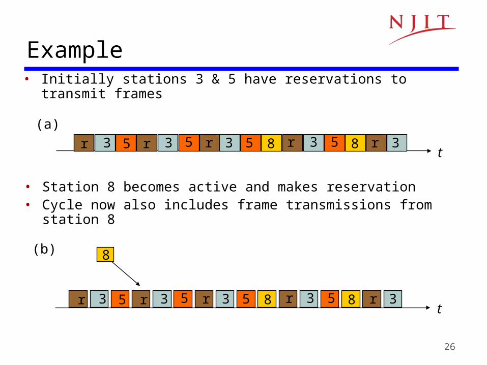
Example• Initially stations 3 & 5 have reservations to transmit frames
• Station 8 becomes active and makes reservation• Cycle now also includes frame transmissions from station 8
27
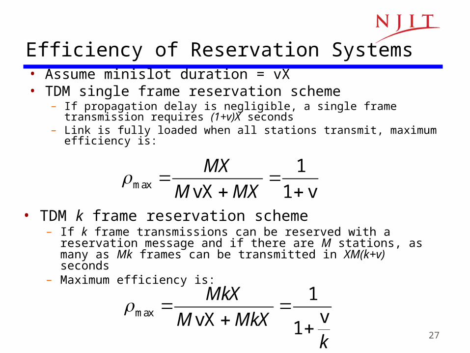
Efficiency of Reservation Systems• Assume minislot duration = vX• TDM single frame reservation scheme
– If propagation delay is negligible, a single frame transmission requires (1+v)X seconds
– Link is fully loaded when all stations transmit, maximum efficiency is:
• TDM k frame reservation scheme– If k frame transmissions can be reserved with a reservation message
and if there are M stations, as many as Mk frames can be transmitted in XM(k+v) seconds
– Maximum efficiency is:
max
1
1
MX
M MX
vX v
max
1
1
MkX
M MkXk
vvX
28
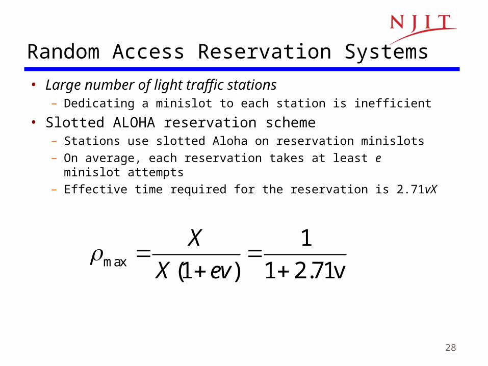
Random Access Reservation Systems
• Large number of light traffic stations– Dedicating a minislot to each station is inefficient
• Slotted ALOHA reservation scheme– Stations use slotted Aloha on reservation minislots– On average, each reservation takes at least e minislot
attempts – Effective time required for the reservation is 2.71vX
max
1
(1 ) 1 2.71
X
X ev
v

29
Example: GPRS
• General Packet Radio Service– Packet data service in GSM cellular radio– GPRS devices, e.g. cellphones or laptops, send packet
data over radio and then to Internet– Slotted Aloha MAC used for reservations– Single & multi-slot reservations supported
30
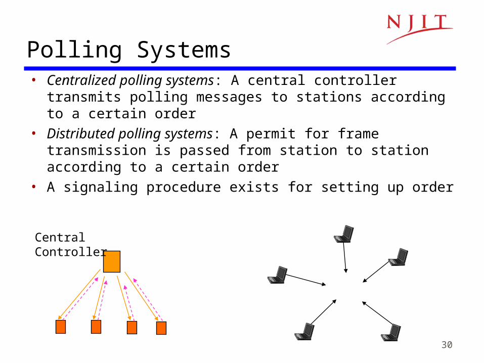
Polling Systems• Centralized polling systems: A central controller transmits
polling messages to stations according to a certain order
• Distributed polling systems: A permit for frame transmission is passed from station to station according to a certain order
• A signaling procedure exists for setting up order
CentralController

31
Polling System Options
• Service Limits: How much is a station allowed to transmit per poll? – Exhaustive: until station’s data buffer is empty
(including new frame arrivals)– Gated: all data in buffer when poll arrives– Frame-Limited: one frame per poll– Time-Limited: up to some maximum time
• Priority mechanisms– More bandwidth & lower delay for stations that appear
multiple times in the polling list– Issue polls for stations with message of priority k or
higher
33
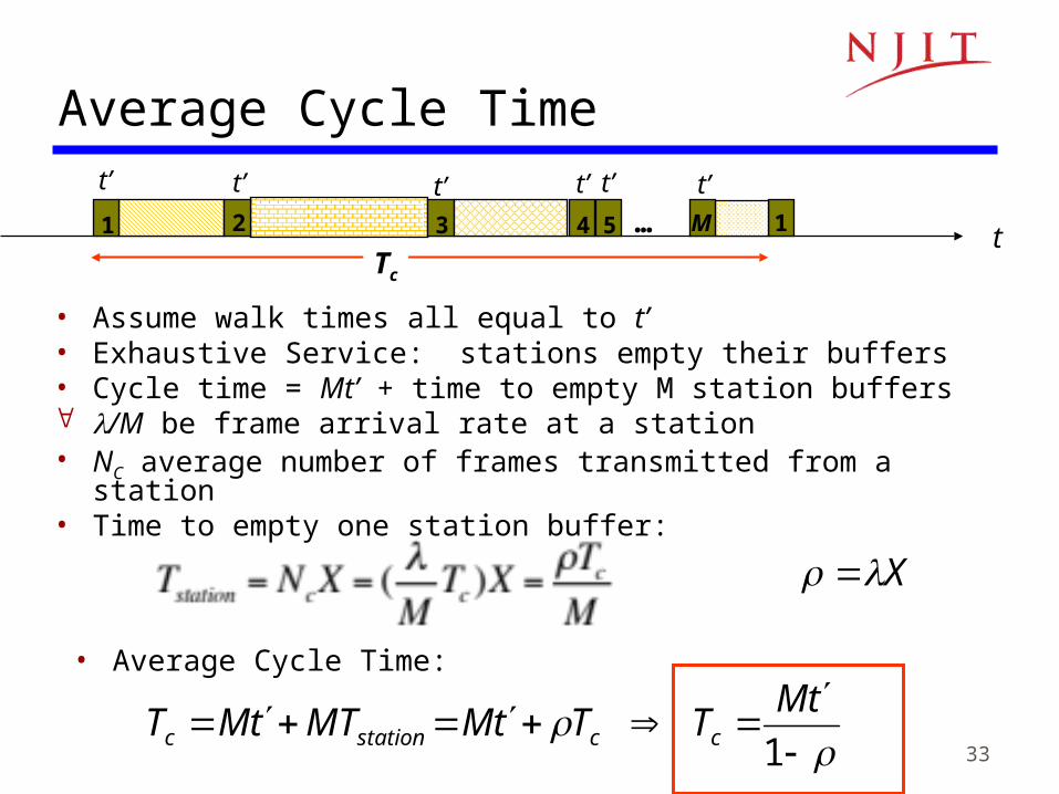
Average Cycle Time
• Assume walk times all equal to t’• Exhaustive Service: stations empty their buffers• Cycle time = Mt’ + time to empty M station buffers /M be frame arrival rate at a station• NC average number of frames transmitted from a station• Time to empty one station buffer:
t1 32 4 5 1… M
t’ t’ t’ t’ t’ t’
Tc
• Average Cycle Time:
1
tM
TTtMMTtMT ccstationc
X
34
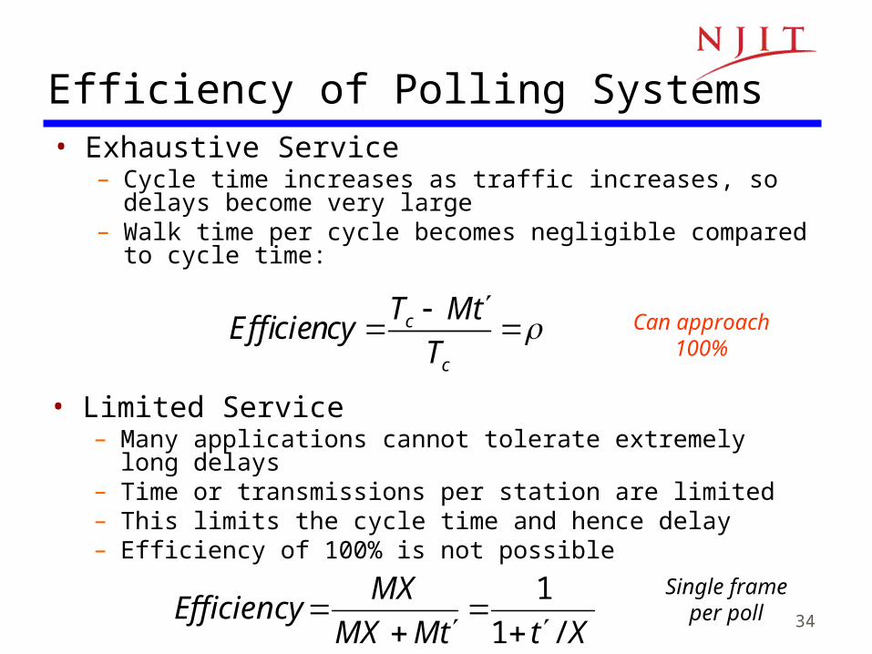
Efficiency of Polling Systems• Exhaustive Service
– Cycle time increases as traffic increases, so delays become very large
– Walk time per cycle becomes negligible compared to cycle time:
c
c
T MtEfficiency
T
Can approach
100%
• Limited Service– Many applications cannot tolerate extremely long delays– Time or transmissions per station are limited– This limits the cycle time and hence delay– Efficiency of 100% is not possible
XttMMX
MXEfficiency
/1
1
Single frame
per poll
35
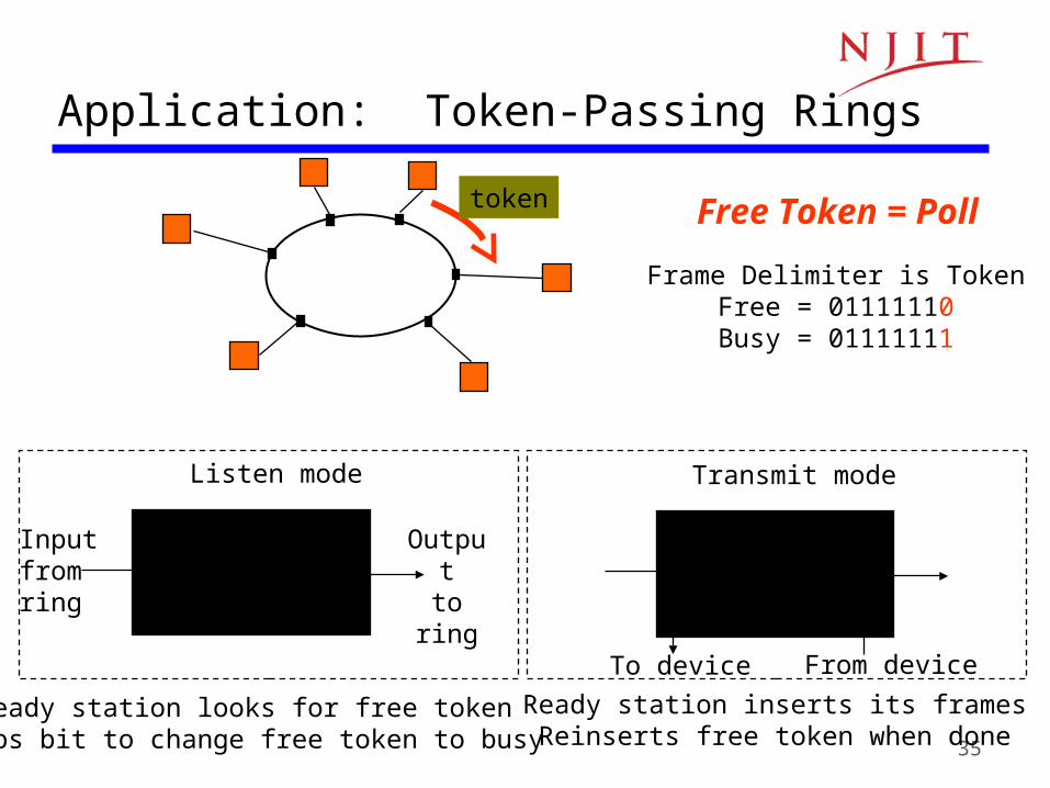
Application: Token-Passing Rings
Free Token = Poll
Listen mode
DelayInputfromring
Outputto
ring
Ready station looks for free tokenFlips bit to change free token to busy
Transmit mode
Delay
To device From device
Ready station inserts its framesReinserts free token when done
token
Frame Delimiter is TokenFree = 01111110Busy = 01111111
36
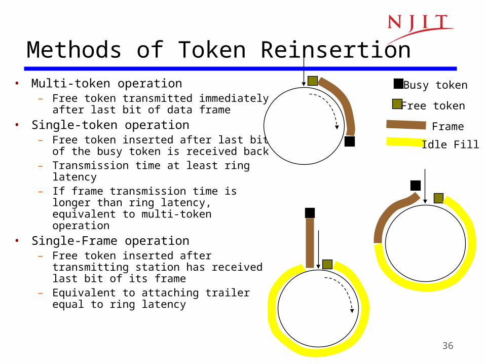
Methods of Token Reinsertion• Multi-token operation
– Free token transmitted immediately after last bit of data frame
• Single-token operation– Free token inserted after last bit of the busy
token is received back– Transmission time at least ring latency– If frame transmission time is longer than ring
latency, equivalent to multi-token operation
• Single-Frame operation– Free token inserted after transmitting station
has received last bit of its frame– Equivalent to attaching trailer equal to ring
latency
Busy token
Free token
Frame
Idle Fill
37
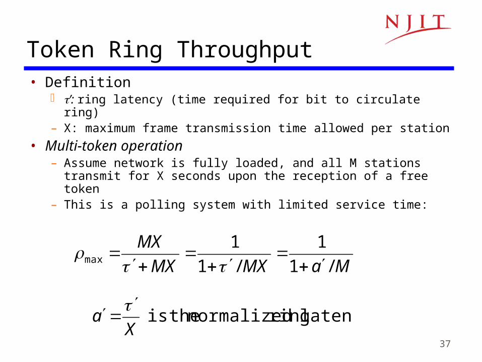
Token Ring Throughput• Definition
’: ring latency (time required for bit to circulate ring)– X: maximum frame transmission time allowed per station
• Multi-token operation– Assume network is fully loaded, and all M stations transmit for X
seconds upon the reception of a free token– This is a polling system with limited service time:
MaMXMX
MX
/1
1
/1
1max
latency ring normalized theis X
a
38
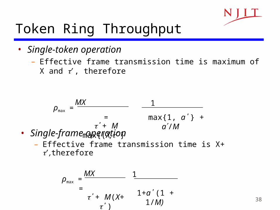
• Single-token operation– Effective frame transmission time is maximum of X and ’ ,
therefore
Token Ring Throughput
ρmax = = MX
΄+ M(X+ ΄)
1 1+a΄(1 +
1/M)
ρmax = =
MX
΄+ M max{(X,΄}
1
max{1, a΄} + a΄/M
• Single-frame operation– Effective frame transmission time is X+ ’ ,therefore
39
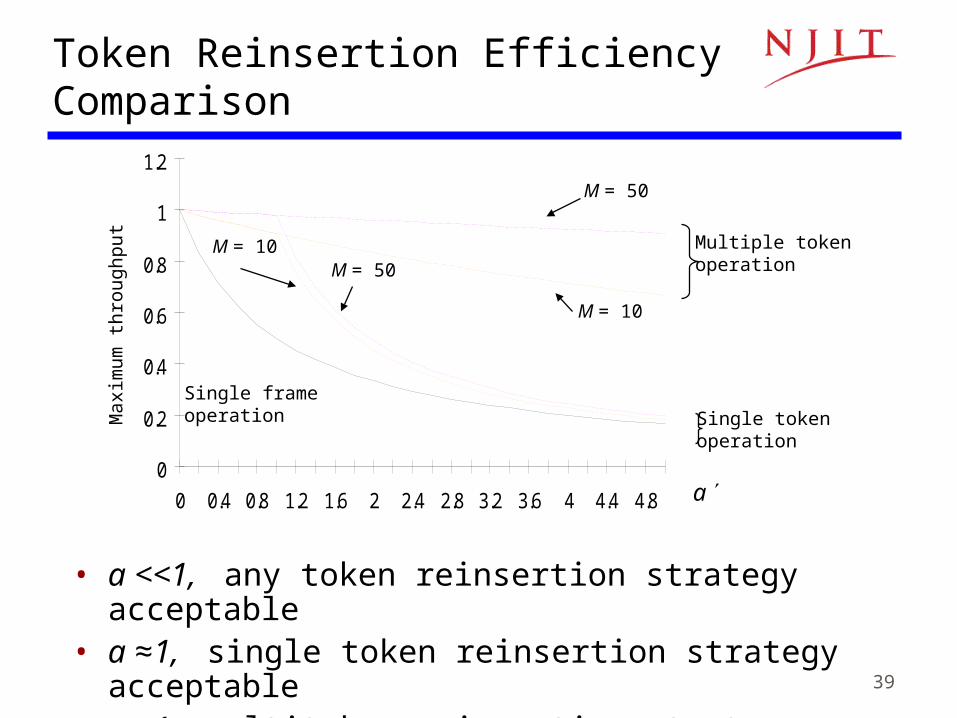
Token Reinsertion Efficiency ComparisonM
axim
um t
hro
ughp
ut
a
Multiple tokenoperation
0
0.2
0.4
0.6
0.8
1
1.2
0 0.4 0.8 1.2 1.6 2 2.4 2.8 3.2 3.6 4 4.4 4.8
Single frameoperation
M = 50
M = 10
Single tokenoperation
M = 50M = 10
• a <<1, any token reinsertion strategy acceptable• a ≈1, single token reinsertion strategy acceptable• a >1, multitoken reinsertion strategy necessary

40
Application Examples
• Single-frame reinsertion– IEEE 802.5 Token Ring LAN @ 4 Mbps
• Single token reinsertion– IBM Token Ring @ 4 Mbps
• Multitoken reinsertion– IEEE 802.5 and IBM Ring LANs @ 16 Mbps– FDDI Ring @ 50 Mbps
• All of these LANs incorporate token priority mechanisms
41
Comparison of MAC approaches
• Aloha & Slotted Aloha– Simple & quick transfer at very low load– Accommodates a large number of low-traffic bursty users– Highly variable delay at moderate loads– Efficiency does not depend on a
• CSMA-CD– Quick transfer and high efficiency for low delay-bandwidth
product– Can accommodate a large number of bursty users– Variable and unpredictable delay
42
Comparison of MAC approaches
• Reservation– On-demand transmission of bursty or steady streams– Accommodates large number of low-traffic users with slotted
Aloha reservations– Can incorporate QoS– Handles large delay-bandwidth product via delayed grants
• Polling– Generalization of time-division multiplexing– Provides fairness through regular access opportunities– Can provide bounds on access delay– Performance deteriorates with large delay-bandwidth product

43
Note 6: Medium Access Control Protocols
Channelization
44
Why Channelization?
• Channelization– Semi-static bandwidth allocation of portion of shared
medium to a given user
• Highly efficient for constant-bit rate traffic• Preferred approach in
– Cellular telephone networks– Terrestrial & satellite broadcast radio & TV
45
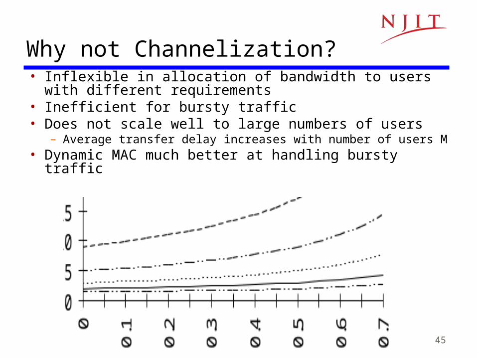
Why not Channelization?• Inflexible in allocation of bandwidth to users with different
requirements• Inefficient for bursty traffic• Does not scale well to large numbers of users
– Average transfer delay increases with number of users M• Dynamic MAC much better at handling bursty traffic
46
Channelization Approaches
• Frequency Division Multiple Access (FDMA)– Frequency band allocated to users– Broadcast radio & TV, analog cellular phone
• Time Division Multiple Access (TDMA)– Periodic time slots allocated to users– Telephone backbone, GSM digital cellular phone
• Code Division Multiple Access (CDMA)– Code allocated to users– Cellular phones, 3G cellular
47
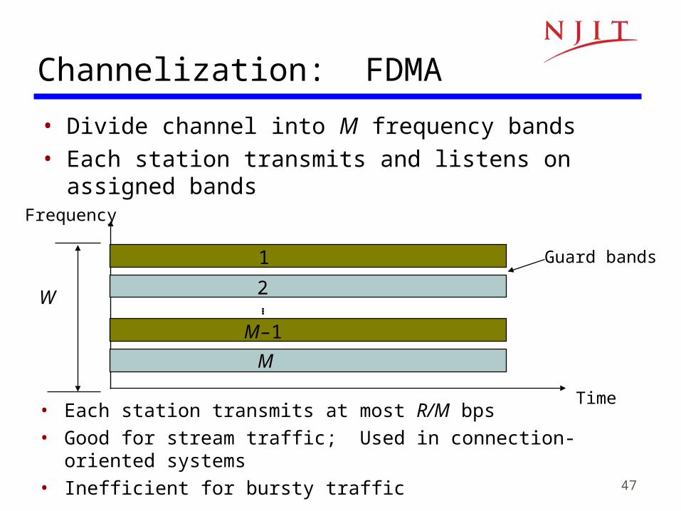
Channelization: FDMA
• Divide channel into M frequency bands• Each station transmits and listens on assigned bands
• Each station transmits at most R/M bps• Good for stream traffic; Used in connection-oriented systems• Inefficient for bursty traffic
Frequency
Guard bands
Time
W
1
2
M
M–1
…
48
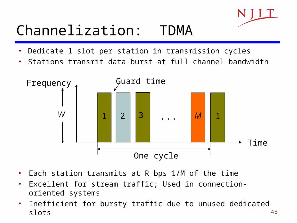
Channelization: TDMA• Dedicate 1 slot per station in transmission cycles• Stations transmit data burst at full channel bandwidth
• Each station transmits at R bps 1/M of the time
• Excellent for stream traffic; Used in connection-oriented systems
• Inefficient for bursty traffic due to unused dedicated slots
1
Time
Guard time
One cycle
12 3 MW
Frequency
...
49
Guardbands
• FDMA– Frequency bands must be non-overlapping to prevent
interference– Guardbands ensure separation; form of overhead
• TDMA– Stations must be synchronized to common clock– Time gaps between transmission bursts from different
stations to prevent collisions; form of overhead– Must take into account propagation delays
50
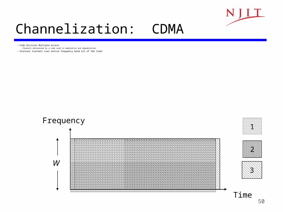
Channelization: CDMA• Code Division Multiple Access
– Channels determined by a code used in modulation and demodulation
• Stations transmit over entire frequency band all of the time!
Time
W
Frequency1
2
3
51
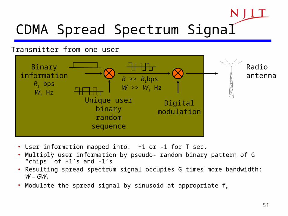
Binaryinformation
R1 bpsW1 Hz
Unique user binary random
sequence
Digitalmodulation
Radio antenna
Transmitter from one user
R >> R1bpsW >> W1 Hz
CDMA Spread Spectrum Signal
• User information mapped into: +1 or -1 for T sec.• Multiply user information by pseudo- random binary pattern of G “chips” of +1’s
and -1’s • Resulting spread spectrum signal occupies G times more bandwidth: W = GW1
• Modulate the spread signal by sinusoid at appropriate fc
52
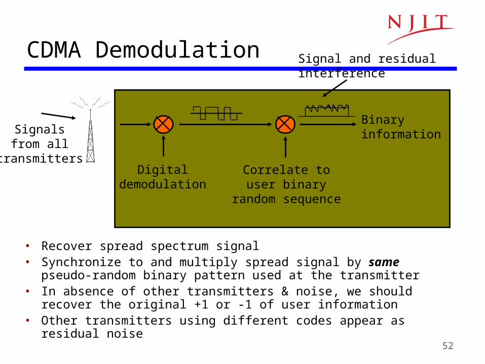
Signal and residualinterference
Correlate touser binary
random sequence
Signalsfrom all
transmittersDigital
demodulation
Binaryinformation
CDMA Demodulation
• Recover spread spectrum signal• Synchronize to and multiply spread signal by same pseudo-random
binary pattern used at the transmitter• In absence of other transmitters & noise, we should recover the original
+1 or -1 of user information• Other transmitters using different codes appear as residual noise
53
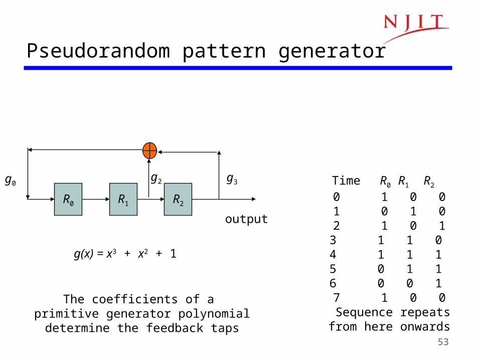
R0 R1 R2
g(x) = x3 + x2 + 1
g0g2 g3
The coefficients of a primitive generator polynomialdetermine the feedback taps
Time R0 R1 R2
0 1 0 01 0 1 02 1 0 13 1 1 0 4 1 1 1 5 0 1 1 6 0 0 1 7 1 0 0
Sequence repeatsfrom here onwards
output
Pseudorandom pattern generator
54
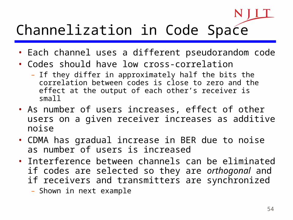
Channelization in Code Space
• Each channel uses a different pseudorandom code• Codes should have low cross-correlation
– If they differ in approximately half the bits the correlation between codes is close to zero and the effect at the output of each other’s receiver is small
• As number of users increases, effect of other users on a given receiver increases as additive noise
• CDMA has gradual increase in BER due to noise as number of users is increased
• Interference between channels can be eliminated if codes are selected so they are orthogonal and if receivers and transmitters are synchronized– Shown in next example
55
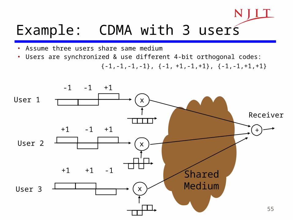
Example: CDMA with 3 users• Assume three users share same medium• Users are synchronized & use different 4-bit orthogonal codes:
{-1,-1,-1,-1}, {-1, +1,-1,+1}, {-1,-1,+1,+1}
+1 -1 +1
User 1 x
-1 -1 +1
User 2 x
User 3 x
+1 +1 -1 SharedMedium
+
Receiver
56
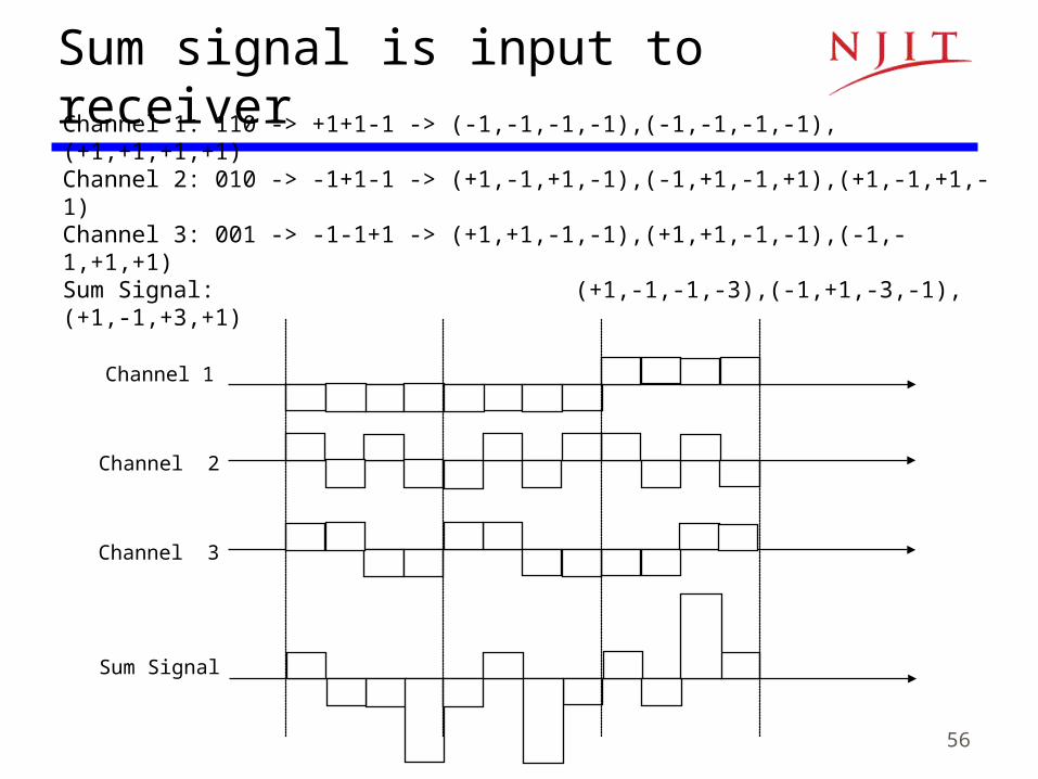
Channel 1: 110 -> +1+1-1 -> (-1,-1,-1,-1),(-1,-1,-1,-1),(+1,+1,+1,+1)Channel 2: 010 -> -1+1-1 -> (+1,-1,+1,-1),(-1,+1,-1,+1),(+1,-1,+1,-1)Channel 3: 001 -> -1-1+1 -> (+1,+1,-1,-1),(+1,+1,-1,-1),(-1,-1,+1,+1)Sum Signal: (+1,-1,-1,-3),(-1,+1,-3,-1),(+1,-1,+3,+1)
Channel 1
Channel 2
Channel 3
Sum Signal
Sum signal is input to receiver
57
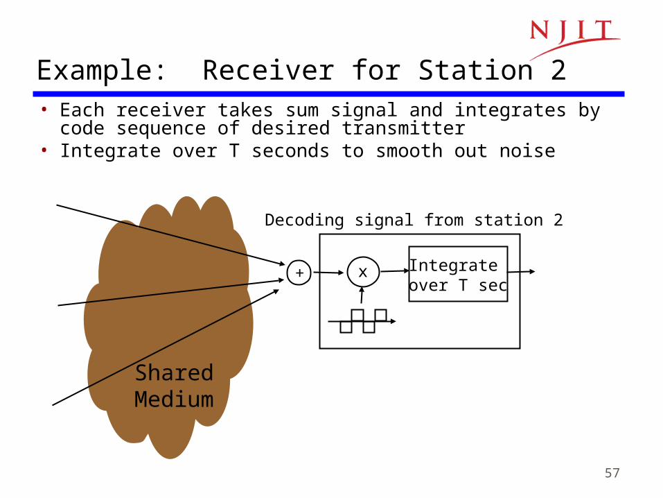
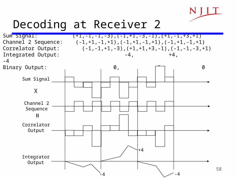
Example: Receiver for Station 2• Each receiver takes sum signal and integrates by code
sequence of desired transmitter• Integrate over T seconds to smooth out noise
x
SharedMedium
+
Decoding signal from station 2
Integrate over T sec
58
Sum Signal: (+1,-1,-1,-3),(-1,+1,-3,-1),(+1,-1,+3,+1) Channel 2 Sequence: (-1,+1,-1,+1),(-1,+1,-1,+1),(-1,+1,-1,+1)Correlator Output: (-1,-1,+1,-3),(+1,+1,+3,-1),(-1,-1,-3,+1)Integrated Output: -4, +4, -4Binary Output: 0, 1, 0
Sum Signal
Channel 2Sequence
CorrelatorOutput
IntegratorOutput
-4
+4
-4
Decoding at Receiver 2
X
=
59
W1= 0 W2=0 00 1
W4= 0 00 1
0 00 1
0 00 11 11 0
W8=
0 00 1
0 00 1
0 00 11 11 0
0 00 1
0 00 1
0 00 11 11 0
0 00 1
0 00 1
0 00 11 11 0
1 11 0
1 11 0
1 11 00 00 1
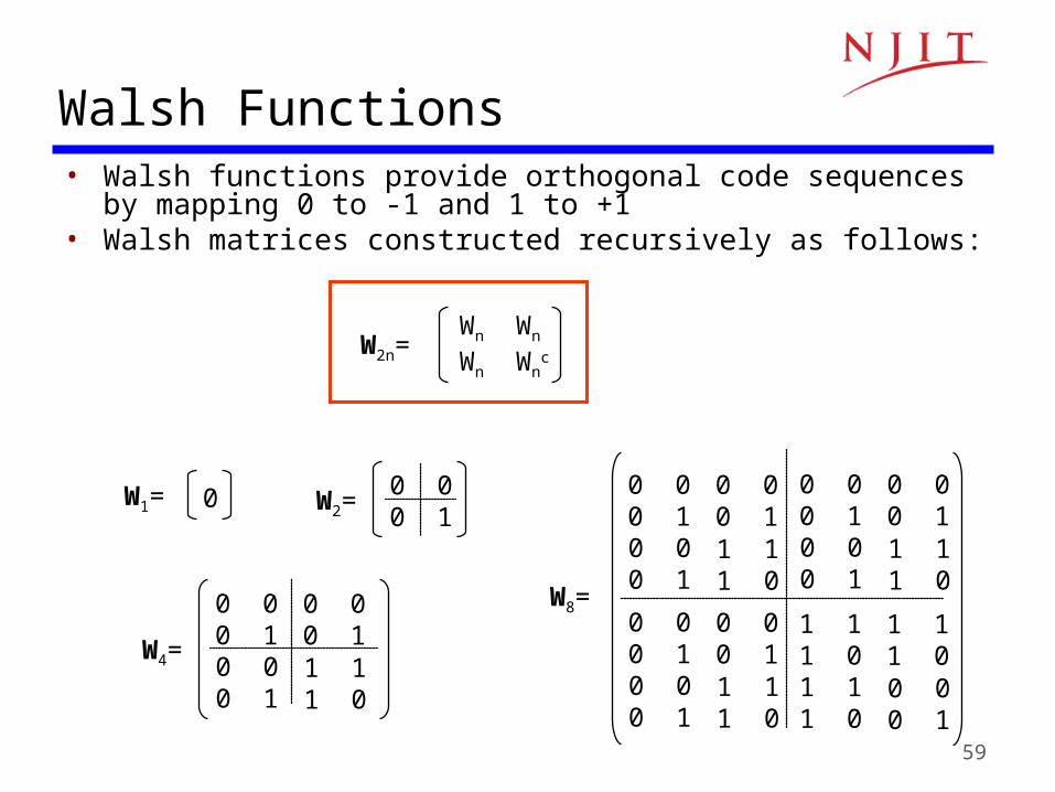
Walsh Functions• Walsh functions provide orthogonal code sequences by mapping 0
to -1 and 1 to +1• Walsh matrices constructed recursively as follows:
W2n=Wn Wn
Wn Wnc
60
Channelization in Cellular Telephone Networks
• Cellular networks use frequency reuse– Band of frequencies reused in other cells that are
sufficiently far that interference is not a problem– Cellular networks provide voice connections that are
steady streams
• FDMA used in AMPS• TDMA used in IS-54 and GSM • CDMA used in IS-95
61
Further Reading
• Textbook: 6.1, 6.2, 6.3, 6.4