Embed Size (px)
Citation preview

RADIANT HEATING SYSTEMS
QUIK TRAK® DESIGN AND INSTALLATION MANUAL
Quik Trak® Design and Installation Manual

www.uponorpro.comii
Table of Contents
Uponor Quik Trak® ....................................................................................................... 1Quik Trak Calculations ................................................................................................. 2Installation Methods ................................................................................................... 3Quik Trak Over a Wood Subfloor with Hardwood Floor Covering .................................3Quik Trak Over a Wood Subfloor with Tile/Linoleum Floor Covering ......................... 4Quik Trak Over a Wood Subfloor with Carpet Floor Covering .......................................5Quik Trak Over an Existing Concrete Slab ....................................................................6Quik Trak Radiant Wall Installation...............................................................................7Quik Trak Design and Installation ................................................................................ 8Planning the Quik Trak Installation ..............................................................................8Piping Layout When Running Tubing Above the Floor ................................................ 9Piping Layout with Access from Below the Floor ..................................................... 10Panel Direction ..........................................................................................................11Preliminary Layout .................................................................................................... 12Panel Installation ...................................................................................................... 12Installing Return Panels ............................................................................................ 13Final Floor Preparation ............................................................................................. 14Tubing Installation .................................................................................................... 14Pressure Testing .........................................................................................................15Appendix A — Advanced Design Suite™ (ADS) Worksheet ........................................16Appendix B — Quik Trak Design Worksheet ..............................................................17Appendix C — Radiant Surface Temperature Charts ..................................................18Appendix D — R-value Charts ...................................................................................19Appendix E — Supply Water Temperature Charts ......................................................20Appendix F — Flow Chart .........................................................................................21Appendix G — Hydronic Friction Loss Table ..............................................................22
Quik Trak® Design and Installation Manual is published by
Uponor, Inc. 5925 148th Street West Apple Valley, MN 55124 USA Tel: 800.321.4739 Fax: 952.891.2008 www.uponorpro.com
Uponor Ltd. 2000 Argentia Rd., Plaza 1, Ste. 200 Mississauga, ON L5N 1W1 CANADA Tel: 888.994.7726 Fax: 800.638.9517 www.uponorpro.com
© 2013 Uponor Inc., All rights reserved.
Third Edition June 2013 First Printing September 2000 Printed in the United States of America
Uponor has used reasonable efforts in collecting, preparing and providing quality information and material in this manual. However, system enhancements may result in modification of features or specifications without notice.
Uponor is not liable for installation practices that deviate from this manual or are not acceptable practices within the mechanical trades.

Quik Trak® Design and Installation Manual 1
Uponor makes it easier to keep up with the demand for radiant heating with Quik Trak. This cost-effective, patented, wood-panel system is engineered for wood-frame construction and offers an alternative to joist heating and poured floor underlayment installations. Only 1⁄2" thick, Quik Trak adds minimal height to floors.
Fast, Easy InstallationUponor’s Quik Trak system provides fast, easy and trouble-free installation of radiant heating in retrofit, remodeling and new construction projects. The system incorporates 5⁄16" Wirsbo hePEXTM tubing into the panel. Quik Trak panels are designed with a center groove that provides a tight fit for the 5⁄16" Wirsbo hePEX tubing. In many installations, the low profile of the panels require only a 1⁄2" alteration of the finished floors, doors and entryways.
Quik Trak is easily installed in many types of floor construction:
• Over a suspended wood subfloor
• Over an existing concrete slab
• In wall or ceiling installations
Quik Trak Installation Tools:
q 12" power miter box, slide-cut saw, table saw or circular saw with ripping guide (use new or sharp carbide blade)
q Cordless or corded drill with several quality #2 Phillips bits and/or #2 square-drive bits and a 5⁄8" wood bit
q Jig saw or reciprocating saw and wood cutting blades
q Tape measure
q Square
q Hammer
q Rubber mallet
q ¾" wood chisel
q Chalk line
q Straight tin snips
q Shop vacuum
q Extension cord
q Safety glasses
q PEX tubing cutter (E6081125, E6081128, E6081501)
q Air compressor/air chuck for air testing and powering pneumatic tools
q 100% Silicone Sealant or Quik Trak Sealant (E6050010) (recommended)
q Caulk gun for 10.1 oz. tubes Note: A pneumatic or cordless caulk gun work well for this application.
q Tubing uncoiler (E6061000, E6062000, E6063000) (recommended)
q Router with ½" cutting blade (recommended)
q Quik Trak Installation Tool Kit (E6050000) with Quik Trak Screws (E6051250) (recommended)
Important! Take the time to carefully plan the layout of your Quik Trak design prior to installation. It will save you considerable labor costs on your first project.
Prepping the Panel AreaEnsure the subfloor is clean and free of movement and high spots.
Note: Since Quik Trak panels are considered an underlayment, the subfloor must be rated to carry the load of the structure without including the ½" Quik Trak panels. Make sure all areas that will not have panels (e.g., cabinets, built-ins) are outlined in some way.
Fill all areas that won’t get panels with ½" plywood or other materials. These areas should be left open until the Quik Trak System goes down. This can easily be handled by the carpentry contractor or the radiant installer. Have some ½" plywood on hand for any custom tubing adjustments that may happen due to field changes.
Uponor Quik Trak
Figure 1: Quik Trak Panel
Figure 2: Quik Trak Installation Kit (E6050000)
Figure 3: Quik Trak Return Panel

www.uponorpro.com2
Uponor’s Advanced Design SuiteTM (ADS) software performs heat-loss calculations, guides the system designer through the radiant panel design, provides system requirements and generates a material list. This powerful design tool also offers the contractor a host of business tools for a variety of job-management functions.
The calculation portion of ADS prompts the user to input the tubing type, the design differential temperature and the specifics of floor construction. ADS analyzes the information and calculates a supply water temperature and the amount of tubing and number of panels for the room. The user assigns each room or area to a manifold. The program then calculates loop lengths, flow and feet of head.
If you do not have ADS, perform a room-by-room heat loss. From the heat loss information, divide the BTU/h load per room by the available net floor area (i.e., area that will have installed panels) to determine the BTU/h load per square foot of net floor space.
BTU/h/Room = BTU/h/ft2
Net Floor Area (paneled)
See the design sheet in Appendix B for calculation assistance.
When designing the system, Uponor recommends surface temperatures not exceed 80°F (26.7°C) for a solid wood floor and 87.5°F (30.8°C) for any other floor surface.
Note: If the BTU/h/ft2 load exceeds the BTU/h output of the Quik Trak panels or recommended surface temperature, supplemental heat is required. Uponor’s ADS will give you this information. You can deliver supplemental heat to a specific area by using radiant wall or ceiling, baseboard, radiators or hot-water convectors.
Panel CalculationsTo determine the number of Quik Trak and Return Panels, use the following formulas:
Net Floor Area x 0.386 = Number of Quik Trak panels (round up to the next whole number)
Net Floor Area x 0.043 = Number of Return Panels (round up to the next whole number)
Example
Given a 375-square-foot room, 375 x 0.386 = 145 Quik Trak panels needed 375 x 0.043 = 16 Return Panels needed
Tubing CalculationsTo calculate the amount of tubing needed, multiply the net floor area by 1.7. Divide the total amount of tubing into equal lengths that are less than 250 ft. including the leader length for the loop. Leader length is the distance from the manifold to the
room and back to the manifold plus the vertical distance from the floor to the manifold.
Note: The leader length is doubled to account for supply and return runs.
Example
Given a 375-square-foot room with a leader length of 15 ft. between the room and the manifold location, calculate the number of loops required and the average loop length.
375 square ft. x 1.7 = 638 linear ft.
638 ÷ 3 = 213 ft. average active loop length
15 ft. (leader length) x 2 = 30 ft.
213 + 30 = 243 ft. total loop length
The room will require 3 loops of 243 ft.
The design sheet in Appendix B will help with the process.
Note: Do not exceed 250 ft. for the total loop length.
Quik Trak Calculations
Figure 4: Installing Quik Trak Panels

Quik Trak® Design and Installation Manual 3
Quik Trak Over a Wood Subfloor with Hardwood Floor Covering
How — Lay Quik Trak panels over a plywood subfloor perpendicular to the finished wood floor. Make sure to stagger the seams of the Quik Trak.
Secure panels to the subfloor with 11⁄4" Quik Trak Screws or 1" staples. To start, secure the middle of the panel with a screw or staple. Work from the middle to the ends, alternating from side to side.
After laying the panels, vacuum the debris from the panel grooves. Next, apply a thin, 1⁄8" bead of 100% silicone sealant throughout the entire length of the groove. The sealant acts as an adhesive agent and promotes good heat transfer from the tubing to the panel.
Install the tubing by stepping the tubing into the panel grooves. If you’re not wearing hard-sole shoes, you may need to use a rubber hammer to snap the tubing into the groove.
Where — This application is used in residential construction as an alternative to joist heating and poured-floor underlayment installations. Quik Trak is also beneficial when the finished floor material is hardwood. Installers can actually see the tubing when installing the hardwood floor. This method offers several advantages, including minimal increase in floor height, no moisture from concrete and increased BTU/h/ft2 output potential over joist heating.
What to look for — Take special care when installing hardwood flooring over radiant floors. Please consult Chapter 16 from the Complete Design Assistance Manual (CDAM) for detailed wood floor information.
Always install hardwood floors in accordance with the flooring manufacturer’s instructions. Ensure nails for the finished wood floor are a minimum of 11⁄2 inches away from the tubing.
Note: Do not exceed 80ºF (26.7°C) for hardwood floor surface temperatures.
Proper insulation is critical to the performance of Quik Trak. A minimum of R-19 is recommended in between the floor joists beneath the floor.
In all Quik Trak applications, the maximum loop length for 5⁄16" Wirsbo hePEX tubing is 250 ft., including leader lengths. Flow rates for all Quik Trak installations are calculated to a 20°F (11.1°C) temperature differential.
Installation Methods

www.uponorpro.com4
Quik Trak Over a Wood Subfloor with Tile/Linoleum Floor Covering
How — Lay Quik Trak panels over a plywood subfloor perpendicular to the floor joists. Make sure to stagger the seams of the Quik Trak.
Secure panels to the subfloor with 11⁄4" Quik Trak Screws or 1" staples. To start, secure the middle of the panel with a screw or staple. Work from the middle to the ends, alternating from side to side.
After laying the panels, vacuum the debris from the panel grooves. Next, apply a thin, 1⁄8" bead of 100% silicone sealant throughout the entire length of the groove. The sealant acts as an adhesive agent and promotes good heat transfer from the tubing to the panel.
Install the tubing by stepping the tubing into the panel grooves. If you’re not wearing hard-sole shoes, you may need to use a rubber hammer to snap the tubing into the groove.
Where — This application is used in residential construction as an alternative to joist heating and poured-floor underlayment installations. Quik Trak is also beneficial when the finished floor material is hardwood. Installers can actually see the tubing when installing the hardwood floor. This method offers several advantages, including minimal increase in floor height, no moisture from concrete and increased BTU/h/ft2 output potential over joist heating.
What to look for — Proper insulation is critical to the performance of Quik Trak. A minimum of R-19 is recommended in between the floor joists beneath the floor.
Note: Do not exceed 87.5ºF (30.8°C) for tile and linoleum floor surface temperatures.
In all Quik Trak applications, the maximum loop length for 5⁄16" Wirsbo hePEX tubing is 250 ft., including leader lengths. Flow rates for all Quik Trak installations are calculated to a 20°F (11.1°C) temperature differential.

Quik Trak® Design and Installation Manual 5
Quik Trak Over a Wood Subfloor with Carpet Floor Covering
How — Lay Quik Trak panels over a plywood subfloor perpendicular to the floor joists. Make sure to stagger the seams of the Quik Trak.
Note: For carpet installations, it is necessary to install 6" of plywood material around the perimeter of the room to allow space to install the tack strip and padding.
Secure panels to the subfloor with 11⁄4" Quik Trak Screws or 1" staples. To start, secure the middle of the panel with a screw or staple. Work from the middle to the ends, alternating from side to side.
After laying the panels, vacuum the debris from the panel grooves. Next, apply a thin, 1⁄8" bead of 100% silicone sealant throughout the entire length of the groove. The sealant acts as an adhesive agent and promotes good heat transfer from the tubing to the panel.
Install the tubing by stepping the tubing into the panel grooves. If you’re not wearing hard-sole shoes, you may need to use a rubber hammer to snap the tubing into the groove.
Where — This application is used in residential construction as an alternative to joist heating and poured-floor underlayment installations. Quik Trak is also beneficial when the finished floor material is hardwood. Installers can actually see the tubing when installing the hardwood floor. This method offers several advantages, including minimal increase in floor height, no moisture from concrete and increased BTU/h/ft2 output potential over joist heating.
What to look for — Proper insulation is critical to the performance of Quik Trak. A minimum of R-19 is recommended in between the floor joists beneath the floor.
Note: Do not exceed 87.5ºF (30.8°C) for carpeted floor surface temperatures.
In all Quik Trak applications, the maximum loop length for 5⁄16" Wirsbo hePEX tubing is 250 ft., including leader lengths. Flow rates for all Quik Trak installations are calculated to a 20°F (11.1°C) temperature differential.

www.uponorpro.com6
Quik Trak Over an Existing Concrete Slab
How — First, install a layer of 5⁄8" or 3⁄4" plywood subfloor over the concrete slab. Glue or power-nail the plywood directly to the concrete if a vapor barrier is not required. If a vapor barrier is required, then power-nail the plywood to the concrete slab.
Lay Quik Trak panels over the plywood subfloor. Make sure to stagger the seams of the Quik Trak.
Secure the panels to the subfloor with 1" screws or 1" staples. To start, secure the middle of the panel with a screw or staple. Work from the middle to the ends, alternating from side to side.
After laying the panels, vacuum the debris from the panel grooves. Next, apply a thin, 1⁄8" bead of 100% silicone sealant throughout the entire length of the groove. The sealant acts as an adhesive agent and promotes good heat transfer from the tubing to the panel.
Install the tubing by stepping the tubing into the panel grooves. If you’re not wearing hard-sole shoes, you may need to use a rubber hammer to snap the tubing into the groove.
Where — This application is used in residential construction over existing concrete slabs. The plywood base together with the Quik Trak panel only adds 11⁄8" to 11⁄4" in floor height. It is the ideal solution when retrofitting or remodeling a basement.
What to look for — A high water table will adversely affect the performance of this application. If there is moisture present that cannot be eliminated from the area, do not use this application.
Note: In a basement or walkout application, it is very important to install perimeter and edge insulation for proper design performance.
In all Quik Trak applications, the maximum loop length for 5⁄16" Wirsbo hePEX tubing is 250 ft., including leader lengths. Flow rates for all Quik Trak installations are calculated to a 20°F (11.1°C) temperature differential.

Quik Trak® Design and Installation Manual 7
Quik Trak Radiant Wall Installation
How — Starting at the floor level on the outside wall, install Quik Trak panels parallel to the floor at a maximum of six rows high (42") to avoid interference with window and picture placement. Fasten panels to the studs on both sides of the groove with 1" drywall screws. After installing the panels, attach 1⁄2" furring strips to the remainder of the stud wall, to provide an even base for the sheetrock.
To install the tubing, drill two 5⁄8" holes in the footer plate opposite the tubing return. Feed the supply through the 5⁄8" hole and attach to the supply manifold. Vacuum the grooves. Apply a thin, 1⁄8" bead of 100% silicone sealant into the grooves. Firmly press tubing into the groove. Feed return to the second 5⁄8" hole and attach to the return manifold. Lastly, attach protector plates (strike plates) where the tubing crosses the studs to protect the tubing from puncture.
Where — Radiant wall installations are a low-cost alternative to radiant floor heating and are often installed when radiant floor is not viable. This method is routinely used in retrofit applications. In addition, radiant wall installations are most often used in supplemental heat situations when the radiant floor cannot satisfy the heat loss of a room under design conditions.
What to look for — Do not install tubing in an area where pictures may be hung.
Ensure the supply loop feeds from the top of the panel and works its way to the bottom. This will help eliminate the possibility of air lock in the loop.
Install a minimum of R-19 insulation in the exterior wall behind the Quik Trak panels.
In all Quik Trak applications, the maximum loop length for 5⁄16" Wirsbo hePEX tubing is 250 ft., including leader lengths. Flow rates for all Quik Trak installations are calculated to a 20°F (11.1°C) temperature differential.

www.uponorpro.com8
In a concrete application, you can improve installation time by carefully planning the placement of manifolds and leaders. As shown above, the leaders must run above the floor.
To save time, draw the Quik Trak layout on a piece of paper before you begin the installation.
1. Split the areas that will have panels into even areas based on the number of loops. The number of loops can be determined by using the Design Assistance Sheet in Appendix B or your Uponor ADS program.
2. Select the manifold location.
3. For 7" panels, draw a 28" square in front of the manifold location. The manifold location is the area that will contain the tightly spaced tubing running from the manifold to the panels. This area may be larger or smaller depending upon the number of loops.
4. To begin the panel installation, measure the distance from the outside wall back to the manifold wall. Divide by 0.583 to determine the number of panel rows needed. Any remaining areas less than the width of a panel can be filled with 1⁄2" plywood.
5. Place the panels that will be used for the leaders. Do not fasten them down at this time.
6. Place the Quik Trak and Return Panels to determine the overall placement.
When the panels are in place, fasten the panels using only two screws. This will allow for quick adjustments if needed. Once the layout has been completed, fasten panels with 10 screws.
7. Fill in any small areas that do not have panels with 1⁄2" plywood.
8. When installing the tubing, use staples or U-shaped tube fasteners to hold the tubing down in the area in front of the manifold.
9. After connecting the tubing to the manifold and pressure testing the system, fill in the square area in front of the manifold using 1⁄2" plywood (trimmed to fit) or a cement product that is screed to a level surface.
Note: A combination is also possible. Fill the larger spaces with 1⁄2" plywood pieces and smaller areas with a thinset product. The type of finished flooring will dictate what method is appropriate.
Planning the Quik Trak Installation
Return Panel
Quik Trak Panel
1⁄2"-thick Wood Filler Pieces
Manifold1⁄2"-thick Thinset Material
Screed Level
Wall
Quik Trak Design and Installation

Quik Trak® Design and Installation Manual 9
Carefully plan the Quik Trak layout before installation begins. A well-planned layout will result in equal loop lengths and minimal waste. Placement of the manifold is key to determining the layout. Manifolds can be placed either above or below the floor. Either location needs to be accessible by a service panel if the wall or ceiling below are finished.
Figures 5 and 6 show manifold location in the wall because the floor is inaccessible from below (e.g., over a concrete slab).
Figure 5: Manifold Location in the Wall
Figure 6: Manifold Location in the Wall
Piping Layout When Running Tubing Above the Floor

www.uponorpro.com10
Figures 7 and 8 show manifold locations in the joist cavity. The entire floor area is accessible.
The arrows illustrate the direction of water flow through the tubing. The dotted lines represent the supply and return lines that are beneath the floor.
Figure 7: Manifold Location in the Joist Cavity
Figure 8: Manifold Location in the Joist Cavity
Piping Layout with Access from Below the Floor

Quik Trak® Design and Installation Manual 11
When possible, start with the warmest water on the exterior walls and progress toward the interior of the room. The direction of the panels in the layout dictate the tubing runs.
Figures 9, 10 and 11 show the recommended layout for the panels. The arrows represent the recommended direction of the Quik Trak panels.
Outside Wall
Floor Joists
Outside Wall
Floor Joists
Outside Wall
Floor Joists
Panel Direction
Figure 9: For tile, parquet and linoleum finished floors, install Quik Trak panels perpendicular to the floor joists. This will add strength to the floor and help prevent deflection of the floor.
Figure 10: For carpeted floors, install Quik Trak panels parallel to the exterior wall to allow the warmest water to reach the coldest area first.
Figure 11: For a wood-finished floor covering, install Quik Trak panels perpendicular to the direction of the finished-wood floor boards.

www.uponorpro.com12
Preliminary LayoutAfter determining the direction of the Quik Trak panels, design the layout.
1. Mark any areas where panels will not be installed (e.g., kitchen cabinets).
2. From the wall, measure the width of the Return Panel plus 1⁄4" for a total of 71⁄4" (see Distance A).
3. Snap a chalk line to outline each of the Return Panel walls (see Figure 12).
4. Determine the starting point for the supply panel and snap a chalk line perpendicular to the other chalk lines using a square as a guide.
Note: For accurate results, use a square instead of the wall as a guide.
Panel Installation 1. Use a circular, power miter or
table saw with a carbide blade to cut the Quik Trak panels.
2. Begin by laying the first row of panels parallel to the chalk line.
3. To improve structural integrity, stagger the panels in each row so the seams are not lined up next to each other. If you have to cut the last panel in the first row, you can use the other cut piece to start the second row. As an alternative, you may cut a panel in half and begin the second row. Continue this staggered pattern throughout the installation (see Figure 13).
Note: If the finished floor is hardwood, it may be necessary to install a vapor barrier below the panels. Check with the wood floor installer or manufacturer to determine the proper location and type of vapor barrier needed with their product.
No Panels
A
Panel Direction
A
A
No Panels
Panel Direction
Figure 12: Use a Chalk Line to Outline Return Panel Locations
Figure 13: Stagger Panels So Seams Do Not Line Up

Quik Trak® Design and Installation Manual 13
Panel Installation (cont.)Begin the installation by laying down the Quik Trak panels and anchoring one side of a panel with a screw at both ends (see Figure 14). This allows for quick realignment, if necessary. Once the panels are properly placed, install screws on both sides of a panel. Use ten screws to ensure that the panels are secure (see Figure 15). Using the Quik Trak Installation Tool Kit (E6050000) will speed this process and alleviate strain from bending.
Installing Return PanelsWhen the Quik Trak installation is finished, it is time to install the Return Panels.
1. Place the aluminum strips in the area where the Return Panels will be installed.
2. Trim the aluminum strips with a pair of tin snips as needed.
3. Place the Return Panels so they align with the grooves in the Quik Trak panels. Make sure to maintain a serpentine pattern for proper tubing placement (see Figures 16 and 17).
4. Secure the Return Panels into place using 10 screws. If necessary, you can cut Return Panels to provide 90° bends.
5. When Return Panels are in place, secure the half-moon wood pieces with a single screw to guide tubing turns.
Figure 14: Anchor One Side of a Panel
Figure 16: Correct Panel Placement for Serpentine Pattern
Figure 15: Fasten Panels with 10 Screws
Figure 17: Incorrect Panel Placement

www.uponorpro.com14
Final Floor PreparationUse 1⁄2" plywood or similar product to fill any small areas not covered by panels (see Figure 18). This will make for a completely level surface. When installing panels on a suspended wood floor with access from below, determine the locations of the supply and return holes to the manifolds (see Figures 7 and 8 on page 10).
Note: Leader length is crucial when calculating the number of loops for a given room. When calculating the amount of tubing that is required, remember to add the distance for the leader length to and from the manifolds. Refer to the example given on page 2 of this manual. Also refer to Figures 7 and 8 on page 10.
Tubing InstallationWhen the manifold location is below the subfloor, each supply and return run requires a 3⁄8" Metal Bend Support (A5110375) to ensure tubing alignment through the subfloor. To compensate for the bend in the support, you must create a rectangular slot in the subfloor.
First, use the 5⁄8" drill bit and drill two holes side by side (see Figure 19). Then, use a sharp wood chisel to square off the hole. Trim 1⁄2" of the aluminum backing out of the groove. This will allow the 3⁄8" Metal Bend Support (A5110375) to be flush with the top of the panels (see Figure 20).
Next, vacuum the groove to remove all debris.
Begin the tubing installation by attaching the supply side to the manifold. If the leader comes from under the floor, feed the loop through the floor and attach to the supply manifold.
Fill in Areas
5/8" Hole
Panel
Groove
½"
½" Quik Trak
¾" Subfloor
Aluminum Backing
Figure 19: Drill Two Holes to Create a Rectangler Slot in the Subfloor
Figure 18: When installing the panels in a room with an alcove or bay area, remember to allow enough room for the Return Trak panels. Fill any areas not covered with panels with 1⁄2" plywood.
Figure 20: Trim Aluminum Backing to Allow Bend Support to be Flush with the Top of the Panels

Quik Trak® Design and Installation Manual 15
Figure 21: Insert a 1⁄8" bead of sealant into the panel groove.
Figure 22: Use hard-soled boots or shoes to walk the tubing into the panel groove.
Tubing Installation (cont.)Once the tubing is attached to the supply manifold, secure the 3⁄8" Metal Bend Support to the tube where it comes out of the floor from the supply manifold. It is best to first secure the bend support on the side of the tubing that will remain below the floor. Then position the bend support at the desired point on the tubing and snap the tubing into place. Finally, push the bend support into the hole that you drilled in the Quik Trak groove.
The tubing is now attached to the supply manifold and is through the subfloor. Next, insert a 1⁄8" bead of sealant (see Figure 21). Since the sealant will become tacky in eight to 10 minutes, Uponor recommends applying the sealant to a section that can be covered with tubing in this amount of time. Next, walk the tubing into the groove. Hard-soled boots or shoes are recommended (see Figure 22).
If the tubing does not snap completely into the groove, first check to see if there is some obstruction under the tube. If not, use a rubber mallet or the rubber-coated base of a hammer to tap the tubing into place.
Repeat the process of applying the sealant and placing the tubing into the groove until you are a few feet from the pre-drilled hole for the run back to the return manifold. Slide the tubing through the hole and install a 3⁄8" Metal Bend Support as outlined in (Figure 20). Finish by connecting the tubing to the return manifold. Repeat this procedure for any additional loops on the manifold.
Pressure TestingOnce you are finished with all the loops to a specific manifold, pressure test the system to a minimum of 60 psi for a minimum of 24 hours or to local code requirements. After the system has
been pressure tested and inspected, the finished floor can be installed.
Note: The Quik Trak system should either be under an air test or operating during the installation of the finished floor covering.

www.uponorpro.com16
Plan Information Floor Level ____________________
Room name
Room temp.
Zone number
Gross floor area
Unheated floor area
Net ceiling area
Average wall height
Floor construction*
Floor type**
Floor covering***
Distance to manifold
Assigned to manifold number
Wall 1 (L x H) X X X X X X X X
Wall 2 (L x H) X X X X X X X X
Wall 3 (L x H) X X X X X X X X
Door 1 (L x W) X X X X X X X X
Door 2 (L x W) X X X X X X X X
Window 1 (L x W) X X X X X X X X
Window 2 (L x W) X X X X X X X X
Skylight (L x W) X X X X X X X X
Project Name ___________________________________________________
Project Location _________________________________________________
Contact Person ________________________________________________
Project Information
* Floor Construction Slab on grade = SO Slab below grade = SB Suspended over heated = SH Suspended over unheated = SU
** Floor Type Concrete slab = C Poured underlayment = U Single plates = S Double plates = D Joist (tubing alone) = J Joist TrakTM = JT Quik Trak® = QT
*** R-values are in Appendix D.
Notes
Date Received ___________________________
Date Design Due __________________________
Contact Number __________________________
Design Information
Outdoor design temperature
Default Settings/Components***
Wall R-value
Ceiling R-value
Window R-value
Skylight R-value
Door R-value
Air change/hour
Suspended Floors
Under-floor insulation R-value
Slab-on-grade Floors
Water table present
Under-slab R-value
Water table temperature
Edge R-value
Slab depth
Perimeter R-value
Appendix A — Advanced Design Suite (ADS) Worksheet

Quik Trak® Design and Installation Manual 17
Appendix B — Quik Trak Design WorksheetQ
uik
Tra
k D
esig
n W
orks
heet
Proj
ect
Nam
e: _
____
____
____
____
____
____
_ M
anif
old
Num
ber:
___
__
Loop
1Lo
op 2
Loop
3Lo
op 4
Loop
5Lo
op 6
Loop
7Lo
op 8
Loop
9Lo
op 1
0
ARo
om n
ame
BRo
om s
etpo
int t
emp.
CZo
ne n
umbe
r
DN
et fl
oor a
rea
(ft2 )
EU
pwar
d lo
ad (B
TU/h
/ft2 )
FTo
tal l
oad
(BTU
/h/f
t2 )
GFl
oor s
urfa
ce te
mp.
HTu
bing
siz
e
IFl
oor c
over
ing
R-va
lue
JD
iffer
entia
l tem
p.
KTu
bing
o.c
. dist
ance
(in)
LSu
pply
wat
er te
mp.
MAc
tive
loop
leng
th
NLe
ader
loop
leng
th
OTo
tal l
oop
leng
th
PLo
op fl
ow in
gpm
QLo
op h
ead
pres
sure
(ft)
RLo
op b
alan
cing
turn
s
SQ
uik
Trak
pan
els
TQ
uik
Trak
retu
rns
Man
ifol
d To
tals
USu
pply
wat
er te
mp.
VM
anifo
ld fl
ow in
gpm
WH
ighe
st p
ress
ure
head
(ft)
A E
nter
the
nam
e of
the
room
. The
room
may
ha
ve m
ore
than
one
loop
.
B R
oom
set
poin
t te
mpe
ratu
re is
nor
mal
ly
65°F
(18
.3°C
) fo
r rad
iant
flo
or.
C Z
one
is e
qual
to
ther
mos
tat.
D E
nter
the
am
ount
of
squa
re fo
otag
e us
ed in
th
e ro
om.
E En
ter t
he “
Floo
r Uni
t Lo
ad t
o R
oom
” va
lue
from
AD
S pr
into
ut (
upw
ard
load
).
F En
ter t
he “
Floo
r Uni
t Lo
ad”
valu
e fr
om A
DS
prin
tout
(to
tal l
oad)
.
G (
Row
E/2
) +
Row
B =
flo
or s
urfa
ce
tem
pera
ture
. Do
not
exce
ed
87.5
°F /
30.8
°C fo
r all
floor
s (e
xcep
tion:
w
ood
floor
lim
it is
80°
F/26
.7°C
).
H T
he o
nly
tubi
ng s
ize
avai
labl
e fo
r Qui
k Tr
ak
is 5 ⁄1
6" W
irsbo
heP
EX.
I Re
fer t
o A
ppen
dix
D fo
r flo
or c
over
ing
info
rmat
ion.
J In
dica
te d
iffer
entia
l tem
pera
ture
(2
0°F/
11.1
°C fo
r Qui
k Tr
ak).
K T
ubin
g o.
c. d
ista
nce
is 7
" fo
r Qui
k Tr
ak.
L U
se in
form
atio
n fr
om R
ows
E, I
, K w
ith
App
endi
x E
to o
btai
n th
e su
pply
wat
er
tem
pera
ture
.
M E
nter
the
leng
th o
f tu
bing
inst
alle
d w
ithin
th
e ro
om (
i.e.,
activ
e lo
op).
N E
nter
the
leng
th o
f th
e tu
bing
fro
m t
he ro
om
bein
g he
ated
to
the
resp
ectiv
e m
anifo
ld.
O U
se fo
rmul
a: (
Row
M +
Row
N)
= to
tal
loop
leng
th.
P U
se t
he v
alue
s in
Row
s F
and
M w
ith
App
endi
x F
to o
btai
n th
e flo
w p
er lo
op.
Q U
se t
he v
alue
s in
Row
s O
and
P w
ith
App
endi
x G
to
obta
in t
he h
ead
pres
sure
pe
r loo
p. C
hoos
e th
e ap
prop
riate
sol
utio
n (w
ater
or w
ater
/gly
col s
olut
ion)
.
R T
hese
cel
ls a
re c
alcu
late
d af
ter t
he d
esig
n
is c
ompl
eted
. Use
the
form
ula:
(cu
rren
t lo
op
valu
e in
Row
O x
4)
/ lo
nges
t lo
op le
ngth
on
the
man
ifold
.
S En
ter t
he n
umbe
r of
pane
ls.
(For
7"
o.c.
, mul
tiply
Row
D b
y 0.
386.
)
T E
nter
the
num
ber o
f re
turn
s.
(For
7"
o.c.
, mul
tiply
Row
D b
y 0.
043.
)
U E
nter
hig
hest
tem
pera
ture
fro
m R
ow L
.
V A
dd a
nd e
nter
all
valu
es f
rom
Row
P.
W E
nter
hig
hest
val
ue f
rom
Row
Q.
www.uponorpro.com18
Roo
m s
etpo
int
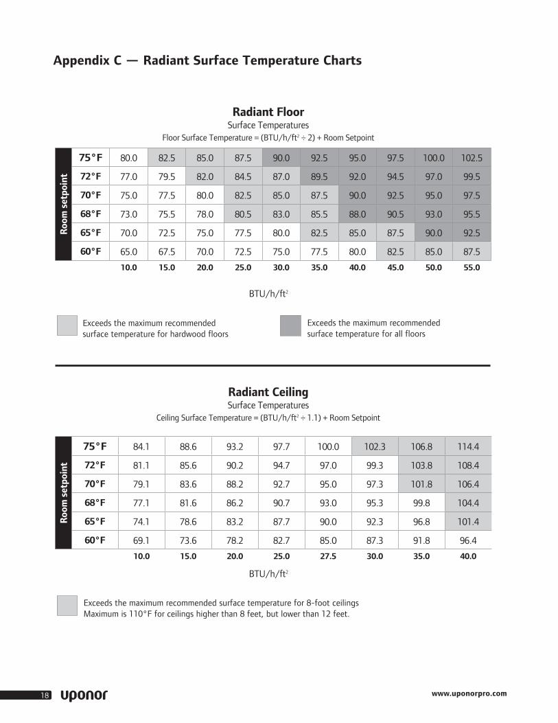
75°F 80.0 82.5 85.0 87.5 90.0 92.5 95.0 97.5 100.0 102.5
72°F 77.0 79.5 82.0 84.5 87.0 89.5 92.0 94.5 97.0 99.5
70°F 75.0 77.5 80.0 82.5 85.0 87.5 90.0 92.5 95.0 97.5
68°F 73.0 75.5 78.0 80.5 83.0 85.5 88.0 90.5 93.0 95.5
65°F 70.0 72.5 75.0 77.5 80.0 82.5 85.0 87.5 90.0 92.5
60°F 65.0 67.5 70.0 72.5 75.0 77.5 80.0 82.5 85.0 87.5
10.0 15.0 20.0 25.0 30.0 35.0 40.0 45.0 50.0 55.0
Exceeds the maximum recommended surface temperature for hardwood floors
Exceeds the maximum recommended surface temperature for all floors
Radiant FloorSurface Temperatures
Floor Surface Temperature = (BTU/h/ft2 ÷ 2) + Room Setpoint
BTU/h/ft2
Roo
m s
etpo
int
75°F 84.1 88.6 93.2 97.7 100.0 102.3 106.8 114.4
72°F 81.1 85.6 90.2 94.7 97.0 99.3 103.8 108.4
70°F 79.1 83.6 88.2 92.7 95.0 97.3 101.8 106.4
68°F 77.1 81.6 86.2 90.7 93.0 95.3 99.8 104.4
65°F 74.1 78.6 83.2 87.7 90.0 92.3 96.8 101.4
60°F 69.1 73.6 78.2 82.7 85.0 87.3 91.8 96.4
10.0 15.0 20.0 25.0 27.5 30.0 35.0 40.0
Exceeds the maximum recommended surface temperature for 8-foot ceilings Maximum is 110°F for ceilings higher than 8 feet, but lower than 12 feet.
Radiant CeilingSurface Temperatures
Ceiling Surface Temperature = (BTU/h/ft2 ÷ 1.1) + Room Setpoint
BTU/h/ft2
Appendix C — Radiant Surface Temperature Charts

Quik Trak® Design and Installation Manual 19
Construction Materials 1⁄8" 1⁄4" 3⁄8" 1⁄2" 5⁄8" 3⁄4"
Plywood (Douglas fir) 0.31 0.47 0.62 0.77 0.93
Oriented strand board (OSB) 0.31 0.47 0.62 0.78 0.94
Asbestos-cement board 0.03 0.06 0.09
Particle board (underlayment) 0.17 0.33 0.49 0.66 0.82
Sheet Goods
Vinyl 0.20
Linoleum (uninsulated) 0.20
Linoleum (insulated) 0.40
Tiles and Stone
Ceramic tile 0.23 0.34 0.45 0.57 0.68
Cork tile 0.28 0.56 0.84
Limestone 0.38 0.50 0.63 0.76
Quarried stone 0.30 0.40 0.50 0.60
Marble 0.20 0.30 0.40 0.50 0.60
Brick 0.38 0.50 0.63 0.76
Carpeting
Commercial glue down 0.60 0.90
Acrylic level loop 1.04 1.56 2.08 2.60 3.12
Acrylic plush 0.83 1.25 1.66 2.08 2.49
Polyester plush 0.96 1.44 1.92 2.40 2.88
Nylon saxony 0.88 1.32 1.76 2.20 2.64
Nylon shag 0.54 0.81 1.08 1.35 1.62
Wool plush 1.10 1.65 2.20 2.75 3.30
Carpet Pads
Rubber (solid) 0.31 0.47 0.62 0.78 0.93
Rubber (waffled) 0.62 0.93 1.24 1.55 1.86
Hair and jute 0.98 1.47 1.96 2.45 2.94
Prime urethane (2-lb. density) 1.08 1.62 2.16 2.70 3.24
Bonded urethane (4-lb. density) 1.04 1.56 2.08 2.60 3.12
Bonded urethane (8-lb. density) 1.10 1.65 2.20 2.75 3.30
Wood Flooring 1⁄8" 1⁄4" 3⁄8" 1⁄2" 5⁄8" 3⁄4"
Ash 0.35 0.47 0.59 0.71
Cherry 0.35 0.46 0.58 0.69
Elm 0.33 0.45 0.56 0.67
Redwood 0.51 0.68 0.84 1.01
Maple 0.35 0.46 0.58 0.69
Oak 0.33 0.45 0.56 0.67
Walnut 0.34 0.45 0.57 0.68
Douglas fir 0.40 0.53 0.66 0.80
Southern pine 0.38 0.50 0.62 0.75
Spruce 0.51 0.68 0.84 1.01
Floating wood floor pad 0.20 0.40
Note: The R-values depicted in this chart are representative and may vary by manufacturer. For specific R-values, check with the appropriate floor covering manufacturer.
Windows
Single glass 0.91
Single glass with storm 2.00
Double glazed – 3⁄16" air space 1.61
Double glazed – ¼" air space 1.69
Double glazed – ½" air space 2.04
Double glazed – 3⁄4" air space 2.38
Double glazed – with suspended film 2.77
Double glazed – with 2 suspended films 3.85
Low-E 3.13
Low-E – with suspended film 4.05
Low-E – with 2 suspended films 5.05
Appendix D — R-value Charts

www.uponorpro.com20
Appendix E — Supply Water Temperature Charts
BTU/h/ft2 Rv = 0.25 Rv = 0.50
Floor Covering Rv
Supply Water Temperature
800
5
10
15
20
25
30
35
40
45
50
90 100 110 120 130 140 150 160 170 180
Rv = 0.75
Rv = 1.0
Rv = 1.5
Rv = 2.0
Rv = 2.5
Rv = 3.0
Differential Temperature20ºF
Quik Trak Radiant Floor65ºF Room Setpoint Temperature
Note: Uponor’s recommended maximum design temperature is 165ºF.
BTU/h/ft2
0
5
10
15
20
25
30
35
40
45
50
½"
80 90 100 110 120 130 140 150 160 170 180
Supply Water Temperature
Exceeds supply water temperature at 20ºF supply/return differential temperature
Differential Temperature20ºF
Quik Trak Radiant Wall70ºF Room Setpoint Temperature
Notes:
1. Chart lines represent ½" and 5⁄8" sheetrock.
2. Do not exceed 120ºF supply water temperature under gypsum sheetrock.
BTU/h/ft2
0
5
10
15
20
25
30
35
40
45
50
½"
80 90 100 110 120 130 140 150 160 170 180
Supply Water Temperature
Exceeds supply water temperature at 20ºF supply/return differential temperature
Differential Temperature20ºF

Quik Trak® Design and Installation Manual 21
Refer to the following instructions to determine the flow per loop for a room.
• The room is 12 ft. by 12 ft. with the tubing installed at 7" o.c. The load for the room is 40 BTU/h/ft2. The room is 15 ft. from the manifold location.
• First determine the amount of tubing in the room.
12 x 12 = 144 sq. ft. 144 x 1.333 = 192 ft. There is 192 ft. of active loop in the room.
• Next, determine the amount of leader length from the room to the manifold location. The distance from the room to the manifold location is 15 ft. The distance is doubled to account for the supply and return tubing.
15 x 2 = 30 ft. Vertical distance of tubing at the manifold = 3 ft.
30 + 6 = 36 ft. There is 36 feet of leader length for this loop.
• Total loop length is the active and leader length added together. 192 + 36 = 228 total loop length
• Determine the flow for the loop by accessing data from the flow chart at right.
1. Enter the chart at the BTU/h/ft2 for the room (40) to get the value in gallons per minute (gpm) per foot of tubing (0.00236).
2. Multiply the active loop length by the value found in the line above. 192 x 0.00236 = 0.45 gpm
3. Flow for the loop is 0.45 gpm.
100% Water at 120ºF (48.9°C) 20ºF (11.1°C) Supply/Return Differntial Flow in GPM Per Foot of Tubing
BTU/h/ft2 7" tubing on-center distance
50 0.00296
49 0.00290
48 0.00284
47 0.00278
46 0.00272
45 0.00266
44 0.00260
43 0.00254
42 0.00248
41 0.00242
40 0.00236
39 0.00231
38 0.00225
37 0.00219
36 0.00213
35 0.00207
34 0.00201
33 0.00195
32 0.00189
31 0.00183
30 0.00177
29 0.00171
28 0.00166
Appendix F — Flow Chart
Note: Flow is based on the active loop length in the room. Head pressure drop is computed from the flow for the loop and the total loop length. Do not use the total loop length to determine the flow for the loop. See Appendix G for the hydronic friction loss table.
BTU/h/ft2 7" tubing on-center distance
27 0.00160
26 0.00154
25 0.00148
24 0.00142
23 0.00136
22 0.00130
21 0.00124
20 0.00118
19 0.00112
18 0.00106
17 0.00101
16 0.00095
15 0.00089
14 0.00083
13 0.00077
12 0.000071
11 0.00065
10 0.00059
9 0.00053
8 0.00047
7 0.00041
6 0.00035
5 0.00030

www.uponorpro.com22
Appendix G — Hydronic Friction Loss Table
5⁄16" Uponor PEX-a — 100% Water — Feet of Head per Foot of Tubing
Velocity (ft./sec.)
GPM 80ºF 27ºC
90ºF 32ºC
100ºF38ºC
110ºF 43ºC
120ºF 49ºC
130ºF54ºC
140ºF60ºC
150ºF66ºC
160ºF71ºC
170ºF77ºC
180ºF82ºC
190ºF88ºC
200ºF93ºC
0.5 0.10 0.00908 0.00873 0.00841 0.00814 0.00789 0.00767 0.00747 0.00729 0.00712 0.00697 0.00683 0.00670 0.00659
0.6 0.13 0.01230 0.01183 0.01141 0.01105 0.01072 0.01043 0.01016 0.00992 0.00970 0.00950 0.00931 0.00914 0.00899
0.7 0.15 0.01591 0.01531 0.01479 0.01433 0.01391 0.01354 0.01320 0.01289 0.01261 0.01235 0.01212 0.01190 0.01170
0.8 0.17 0.01990 0.01917 0.01852 0.01795 0.01744 0.01698 0.01657 0.01619 0.01584 0.01552 0.01523 0.01496 0.01471
0.9 0.19 0.02426 0.02338 0.02261 0.02192 0.02131 0.02075 0.02025 0.01979 0.01938 0.01899 0.01864 0.01832 0.01802
1.0 0.21 0.02898 0.02795 0.02703 0.02622 0.02550 0.02484 0.02425 0.02371 0.02322 0.02276 0.02235 0.02197 0.02161
1.1 0.23 0.03405 0.03285 0.03179 0.03085 0.03000 0.02924 0.02856 0.02793 0.02735 0.02682 0.02634 0.02589 0.02548
1.2 0.25 0.03946 0.03808 0.03687 0.03579 0.03482 0.03395 0.03316 0.03243 0.03178 0.03116 0.03061 0.03010 0.02962
1.3 0.27 0.04520 0.04364 0.04226 0.04104 0.03994 0.03895 0.03805 0.03723 0.03648 0.03579 0.03516 0.03458 0.03404
1.4 0.29 0.05127 0.04952 0.04797 0.04660 0.04536 0.04424 0.04324 0.04231 0.04147 0.04068 0.03998 0.03932 0.03871
1.5 0.31 0.05767 0.05572 0.05399 0.05246 0.05107 0.04983 0.04870 0.04767 0.04673 0.04585 0.04506 0.04433 0.04365
1.6 0.33 0.06438 0.06222 0.06031 0.05861 0.05707 0.05569 0.05445 0.05330 0.05226 0.05128 0.05041 0.04959 0.04884
1.7 0.35 0.07141 0.06903 0.06692 0.06505 0.06336 0.06184 0.06047 0.05920 0.05805 0.05698 0.05601 0.05512 0.05428
1.8 0.38 0.07874 0.07614 0.07383 0.07178 0.06993 0.06826 0.06676 0.06537 0.06411 0.06293 0.06187 0.06089 0.05997
1.9 0.40 0.08638 0.08355 0.08103 0.07880 0.07678 0.07496 0.07332 0.07180 0.07043 0.06914 0.06799 0.06692 0.06592
2.0 0.42 0.09433 0.09125 0.08852 0.08609 0.08390 0.08193 0.08014 0.07850 0.07701 0.07561 0.07435 0.07319 0.07210
2.1 0.44 0.10257 0.09924 0.09629 0.09367 0.09130 0.08916 0.08723 0.08545 0.08384 0.08233 0.08097 0.07970 0.07853
2.2 0.46 0.11110 0.10752 0.10434 0.10152 0.09896 0.09666 0.09458 0.09266 0.09092 0.08929 0.08782 0.08646 0.08519
2.3 0.48 0.11993 0.11609 0.11267 0.10964 0.10689 0.10442 0.10219 0.10013 0.09826 0.09650 0.09493 0.09346 0.09210
2.4 0.50 0.12905 0.12494 0.12128 0.11803 0.11509 0.11244 0.11005 0.10784 0.10584 0.10396 0.10227 0.10070 0.09924
2.5 0.52 0.13845 0.13406 0.13015 0.12669 0.12355 0.12072 0.11816 0.11580 0.11367 0.11165 0.10985 0.10817 0.10661
2.6 0.54 0.14814 0.14346 0.13930 0.13561 0.13226 0.12925 0.12653 0.12401 0.12174 0.11959 0.11767 0.11588 0.11422
2.7 0.56 0.15811 0.15314 0.14872 0.14480 0.14124 0.13804 0.13514 0.13247 0.13005 0.12777 0.12572 0.12382 0.12205
2.8 0.58 0.16836 0.16309 0.15841 0.15424 0.15047 0.14708 0.14400 0.14117 0.13860 0.13618 0.13401 0.13199 0.13011
2.9 0.61 0.17888 0.17331 0.16835 0.16395 0.15996 0.15636 0.15311 0.15011 0.14739 0.14483 0.14253 0.14039 0.13840
3.0 0.63 0.18968 0.18380 0.17856 0.17391 0.16970 0.16590 0.16246 0.15929 0.15641 0.15371 0.15128 0.14902 0.14692
3.1 0.65 0.20076 0.19456 0.18904 0.18413 0.17968 0.17568 0.17205 0.16871 0.16568 0.16282 0.16026 0.15788 0.15566
3.2 0.67 0.21210 0.20558 0.19977 0.19460 0.18992 0.18571 0.18189 0.17837 0.17517 0.17217 0.16947 0.16696 0.16462
3.3 0.69 0.22372 0.21686 0.21075 0.20533 0.20041 0.19597 0.19196 0.18826 0.18490 0.18174 0.17890 0.17626 0.17380
3.4 0.71 0.23560 0.22841 0.22200 0.21630 0.21114 0.20648 0.20227 0.19838 0.19486 0.19154 0.18856 0.18579 0.18320
If you need additional assistance or information on Quik Trak systems, please contact Uponor Techinal Services Department at 800.321.4739.
For more information about radiant floor heating systems including installation methods, wiring diagrams, control strategies and product information, consult the Uponor Complete Design Assistance Manual (CDAM).

Quik Trak® Design and Installation Manual 23

Qui
kTra
k_In
sMan
_H47
1_08
13, C
opyr
ight
© 2
013
Upo
nor,
Inc.
Prin
ted
in th
e U
nite
d St
ates
Uponor, Inc. 5925 148th Street West Apple Valley, MN 55124 USA Tel: 800.321.4739Fax: 952.891.2008
Uponor Ltd. 2000 Argentia Rd., Plaza 1, Ste. 200Mississauga, ON L5N 1W1 CANADATel: 888.994.7726Fax: 800.638.9517 www.uponorpro.com