Embed Size (px)
Citation preview

QUIETQ/U Imaging ExperimenT
Osamu Tajima (KEK)QUIET collaboration
1
Age 10-36 sec 380 Kyr 1 Myr 13.8 Gyr
Inflation
reconbination
Dark age
Begin of universe
reionization
Big bang
CMB First starForegronds Today
Galaxies
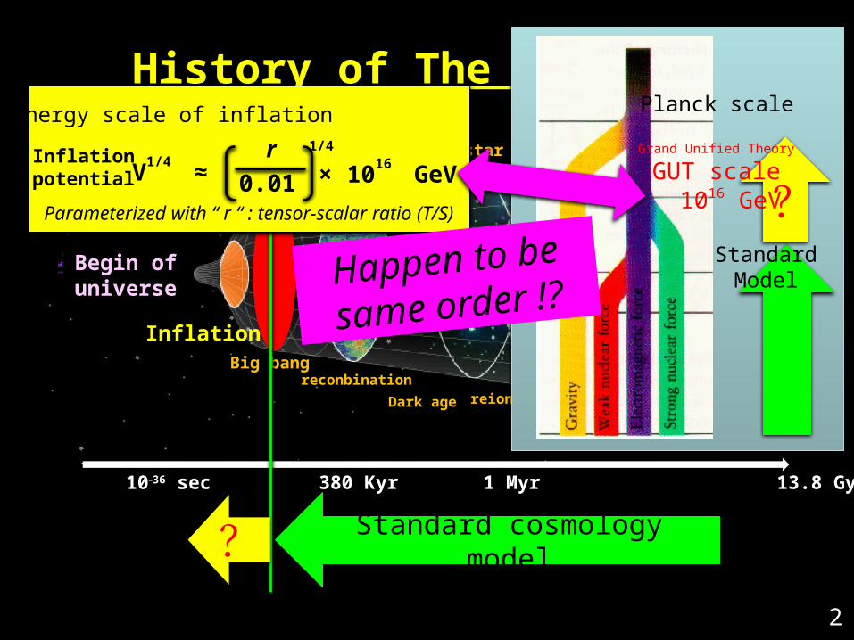
History of The Universe
2
Standard cosmology model?
Inflationpotential × 10
16 GeVV
1/4 ≈ 0.01
1/4 r
Parameterized with “ r “ : tensor-scalar ratio (T/S)
Energy scale of inflation
StandardModel
?Grand Unified Theory
GUT scale 1016 GeV
Planck scale
Happen to be
same order !?
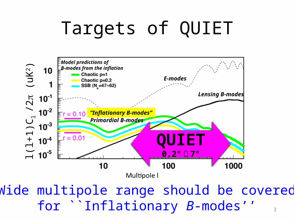
Targets of QUIET
Model predictions of B-modes from the inflation
E-modes
l(l+1
)Cl /
2p (u
K2 )
Lensing B-modes
Primordial B-modes“Inflationary B-modes”
QUIET0.2°〜 7°
3
Wide multipole range should be coveredfor ``Inflationary B-modes’’
Toward Inflationary B modes
• Good systematic error control– Inflationary BB power is less than 1/1,000,000 of
TT, 1/10~1/100 or less of EE– Understanding of Foregrounds– Mitigation of experimental systematics
• Large fields observation– Inflationary BB is significant more than 1o scale– Should be free from experimental 1/f noise
QUIET is designed to fulfill these requirements4
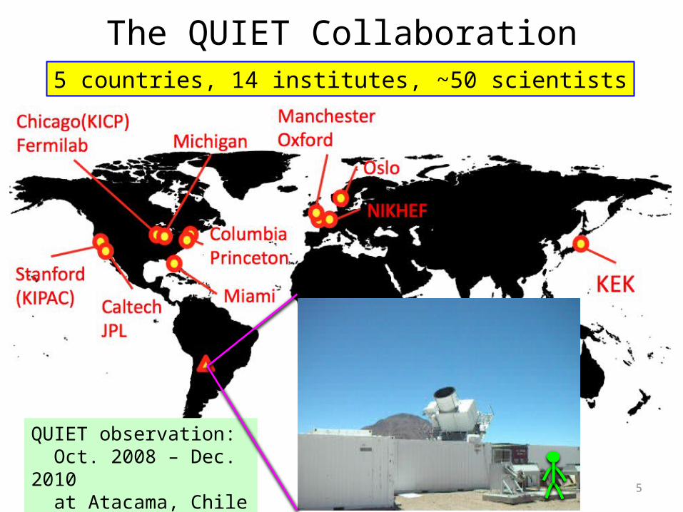
The QUIET Collaboration5 countries, 14 institutes, ~50 scientists
QUIET observation: Oct. 2008 – Dec. 2010 at Atacama, Chile (5,080m) 5
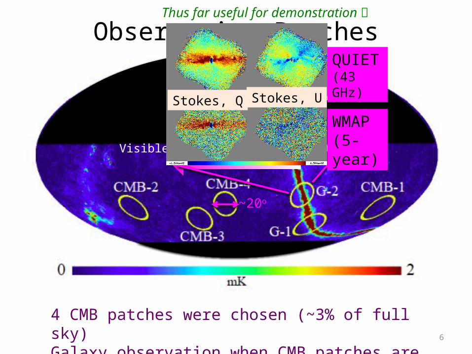
Observation Patches
4 CMB patches were chosen (~3% of full sky)Galaxy observation when CMB patches are not visible
6
~20o
Visible region along earth rotation
QUIET (43 GHz)
WMAP(5-year)
Stokes, Q Stokes, U
Thus far useful for demonstration
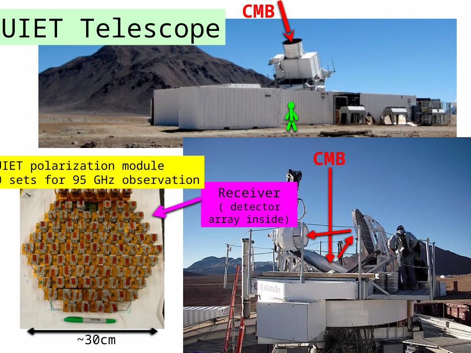
CMBQUIET Telescope
Receiver( detector array inside)
CMB
7~30cm
QUIET polarization module90 sets for 95 GHz observation
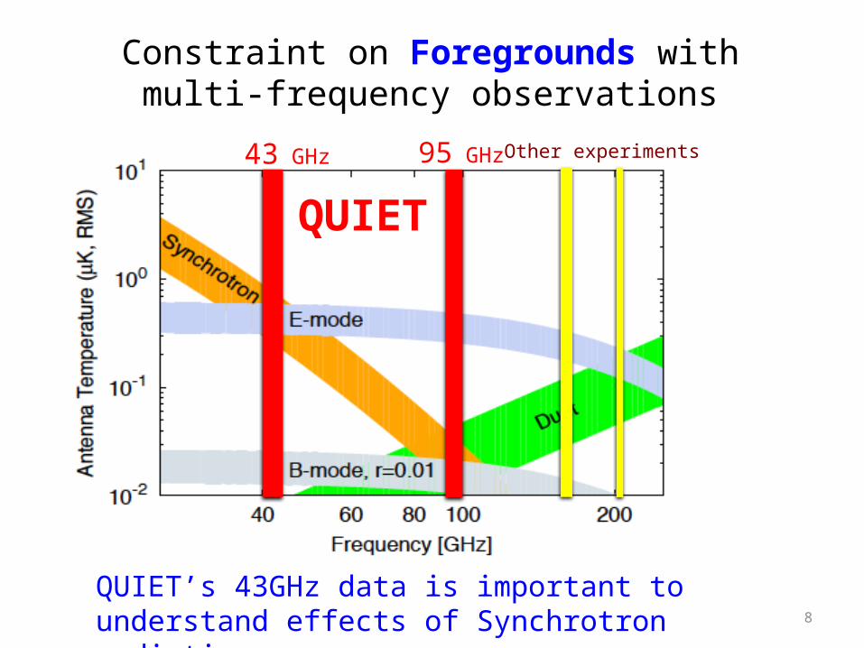
Constraint on Foregrounds with multi-frequency observations
QUIET
Other experiments43 GHz 95 GHz
QUIET’s 43GHz data is important to understand effects of Synchrotron radiations
8
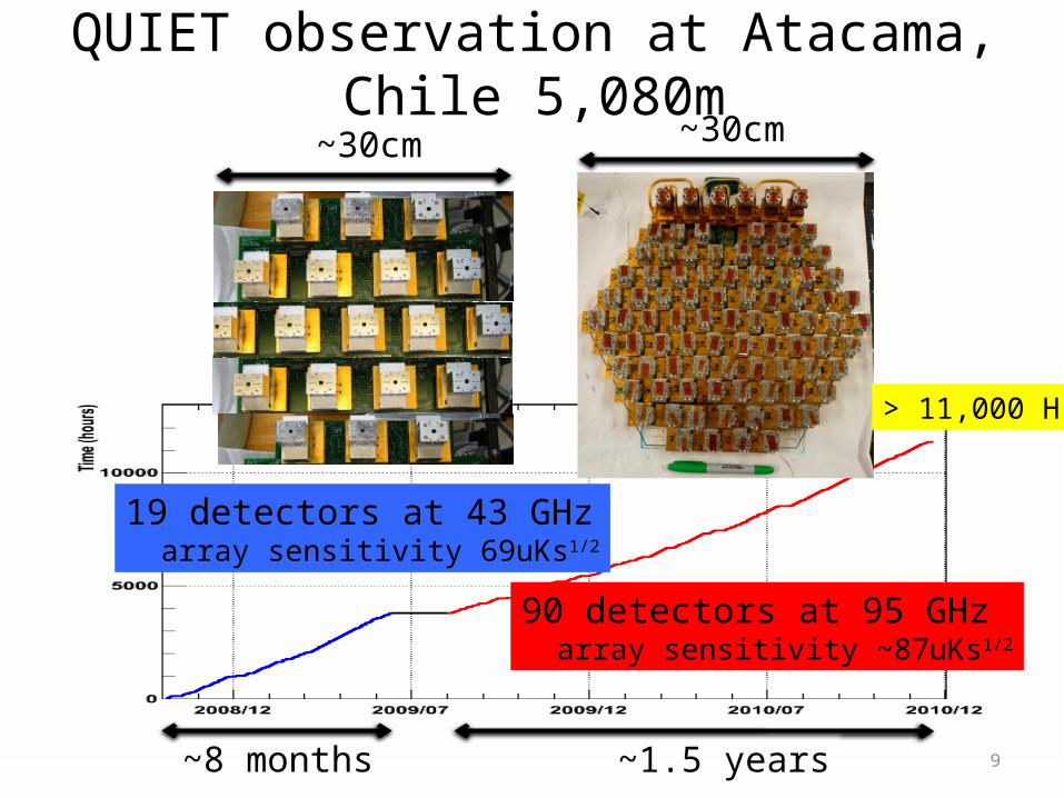
QUIET observation at Atacama, Chile 5,080m
19 detectors at 43 GHz array sensitivity 69uKs1/2
90 detectors at 95 GHz array sensitivity ~87uKs1/2
~30cm ~30cm
~8 months ~1.5 years
> 11,000 H
9
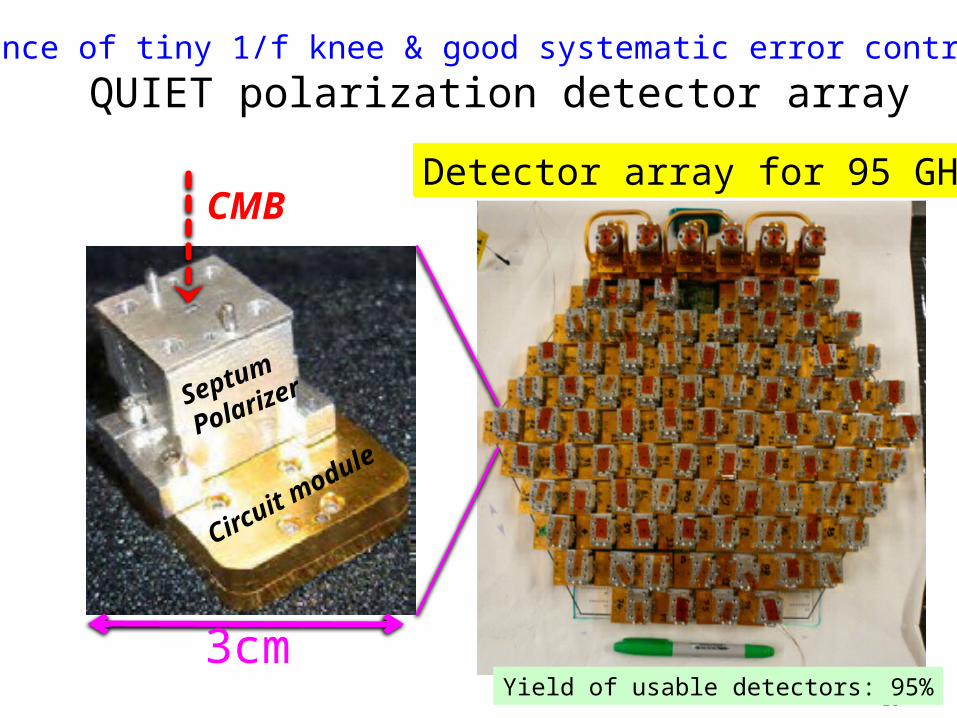
QUIET polarization detector array
CMB
Circuit module
Septum
Polarizer
3cm
Detector array for 95 GHz
Essence of tiny 1/f knee & good systematic error control
10Yield of usable detectors: 95%
DoubleMod.
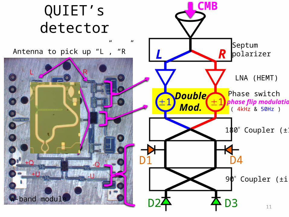
QUIET’s detector
L R
D1
D3D2
±1 1
D4
Septumpolarizer
LNA (HEMT)
Phase switch phase flip modulation ( 4kHz & 50Hz )
180 Coupler (±1)
90 Coupler (±i)
W-band module
Antenna to pick up “L”, “R”
11
CMB
DoubleMod.
D1
D3D2
D4+Q
-U+U
-Q
Phase switch phase flip modulation ( 4kHz & 50Hz )
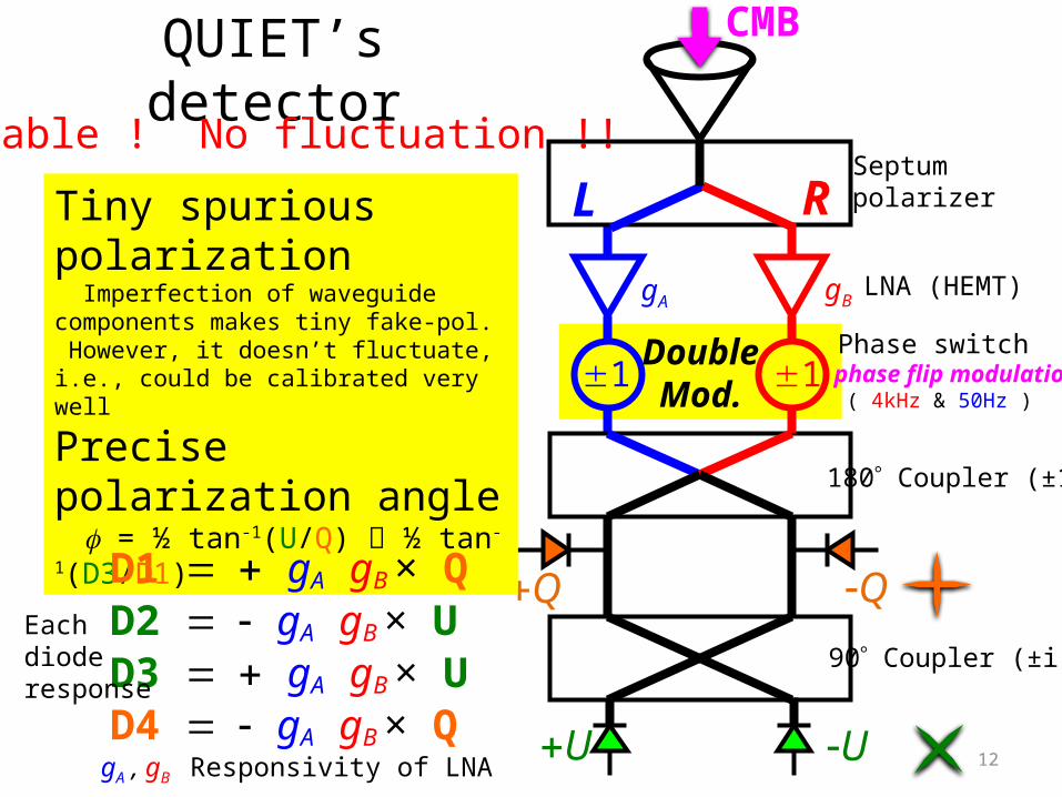
QUIET’s detector
L R
±1 1
gA gB
Septumpolarizer
LNA (HEMT)
180 Coupler (±1)
90 Coupler (±i)
Simultaneous detection of Stokes Q and U!
Tiny spurious polarization Imperfection of waveguide components makes tiny fake-pol. However, it doesn’t fluctuate, i.e., could be calibrated very well
Precise polarization angle f = ½ tan-1(U/Q) ½ tan-1(D3/D1)
Stable ! No fluctuation !!
12
CMB
D1 = + gA gB × QD2 = - gA gB × UD3 = + gA gB × UD4 = - gA gB × Q
Each diode response
gA , gB Responsivity of LNA
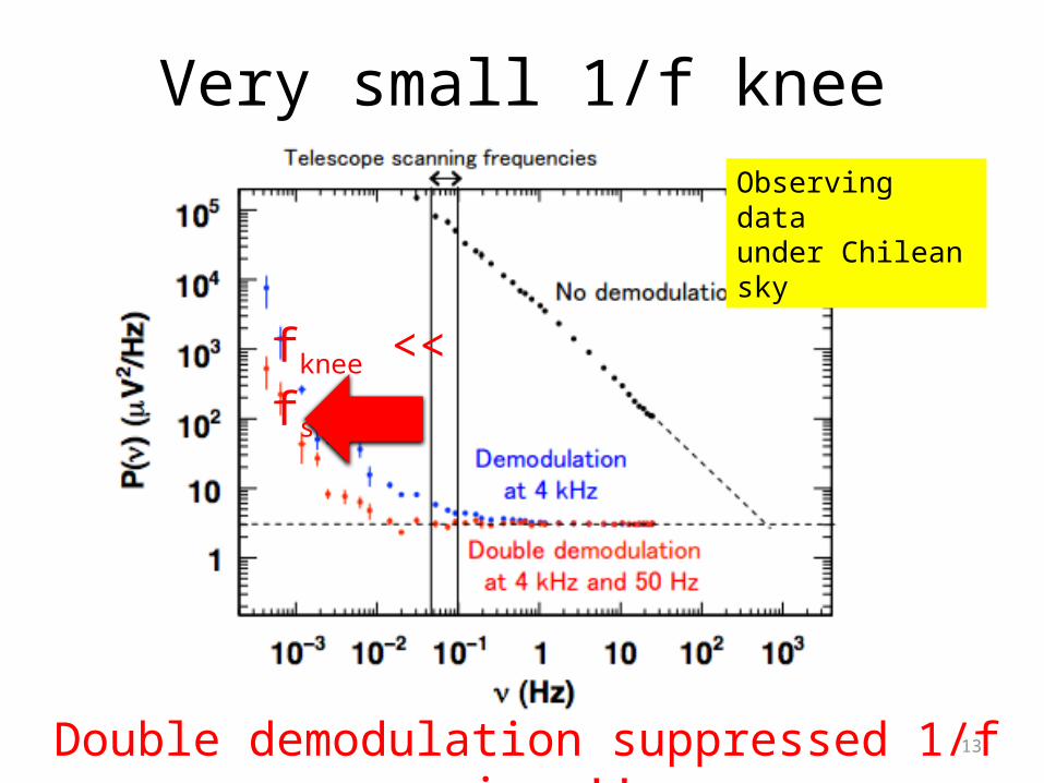
Very small 1/f knee
13
Observing dataunder Chilean sky
fknee << fscan
Double demodulation suppressed 1/f noise !!
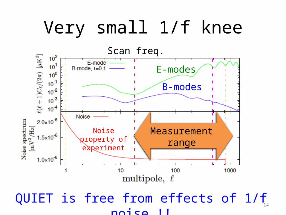
Very small 1/f knee
14
Scan freq.
Noise property of experiment
E-modes
B-modes
Measurement range
QUIET is free from effects of 1/f noise !!
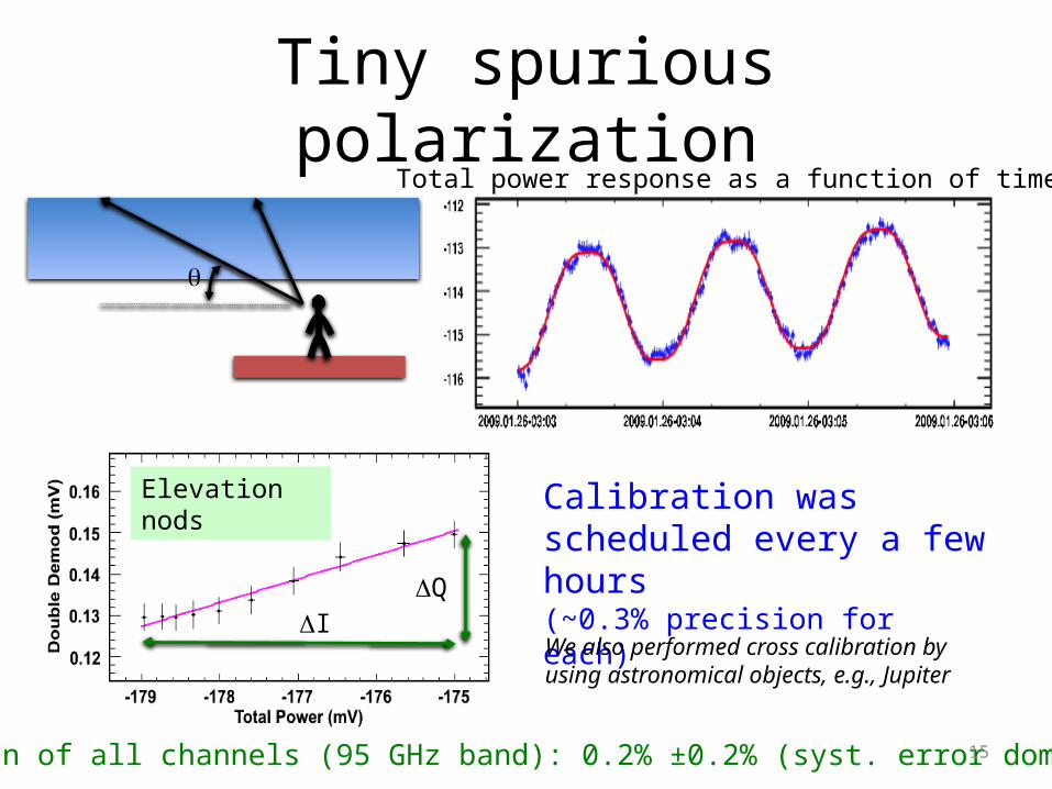
Tiny spurious polarization
Median of all channels (95 GHz band): 0.2% ±0.2% (syst. error dominant)
Calibration was scheduled every a few hours(~0.3% precision for each)
15
q
Total power response as a function of time
We also performed cross calibration by using astronomical objects, e.g., Jupiter
DI
Elevation nods
DQ
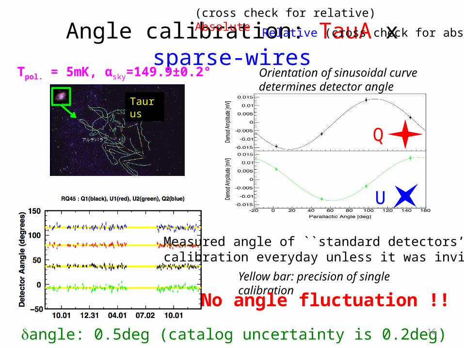
Angle calibration: TauA x sparse-wires(cross check for relative)Absolute Relative (cross check for absolute)
dangle: 0.5deg (catalog uncertainty is 0.2deg) 16
Q
U
Taurus
Tpol. = 5mK, αsky=149.9±0.2° Orientation of sinusoidal curve determines detector angle
Yellow bar: precision of single calibration
Measured angle of ``standard detectors’’calibration everyday unless it was invisible
No angle fluctuation !!

17
(cross check for relative)Absolute Relative (cross check for absolute)
Angle calibration: TauA x sparse-wiresArtificial calibrator, ``sparse wires’’ determined relative angles
Systematic error for relative angle: 0.8o
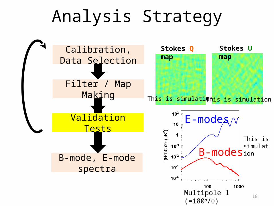
Analysis Strategy
Calibration, Data Selection
Filter / Map Making
B-mode, E-mode spectra
Validation Tests
18
Stokes Q map Stokes U map
Multipole l (=180o/q)
E-modes
B-modes
This is simulation This is simulation
This is simulation
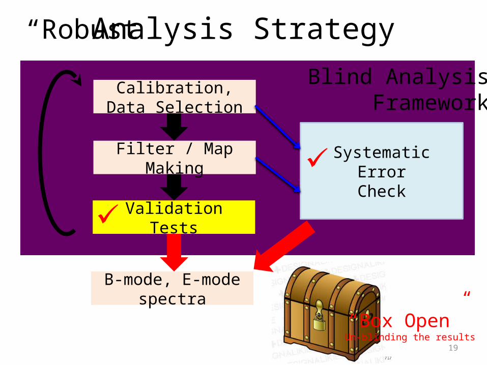
Blind AnalysisFramework
Validation Tests
Analysis Strategy
Calibration, Data Selection
Filter / Map Making
B-mode, E-mode spectra
Systematic ErrorCheck
19
“Robust”
✓
✓
“Box Open” Un-blinding the results
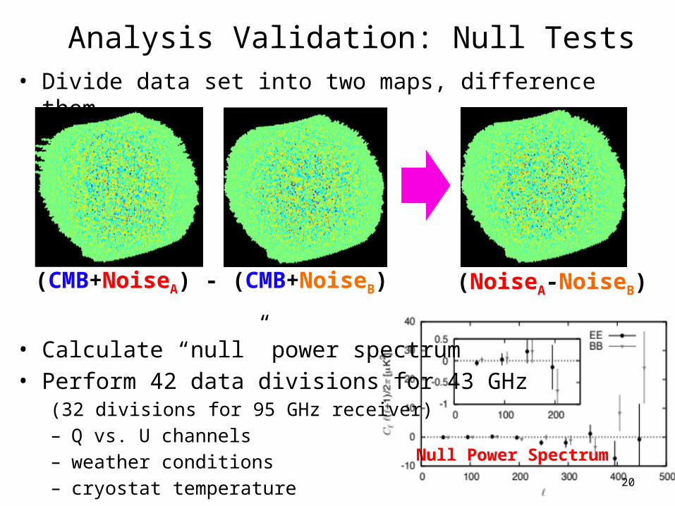
Analysis Validation: Null Tests• Divide data set into two maps, difference them.
• Calculate “null” power spectrum• Perform 42 data divisions for 43 GHz
(32 divisions for 95 GHz receiver)– Q vs. U channels– weather conditions– cryostat temperature
20
(CMB+NoiseA) - (CMB+NoiseB) (NoiseA-NoiseB)
Null Power Spectrum
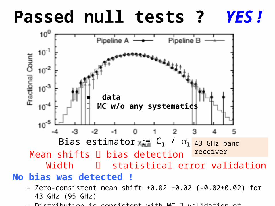
Passed null tests ? YES !
No bias was detected !– Zero-consistent mean shift +0.02 ±0.02 (-0.02±0.02) for 43 GHz (95 GHz)– Distribution is consistent with MC validation of statistical error
● dataー MC w/o any systematics
Bias estimator : = Cl / sl 43 GHz band receiverMean shifts bias detection
Width statistical error validation
22
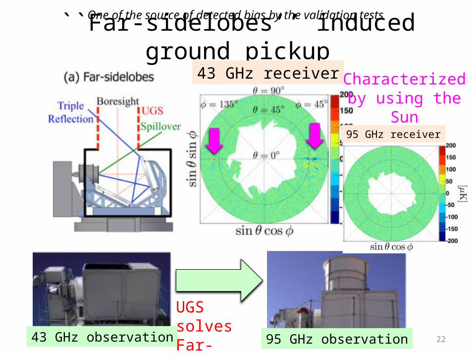
``Far-sidelobes’’ induced ground pickup
43 GHz observation 95 GHz observation
UGS solves Far-sidelobes
Characterized by using the
Sun
43 GHz receiver
95 GHz receiver
One of the source of detected bias by the validation tests

23
Remove effects of ground pickupby far-sidelobes
x 6 different angles
Take cross-correlation10 divisions for Azimuth
X6 divisions of boresight rotations
Motion of each patch
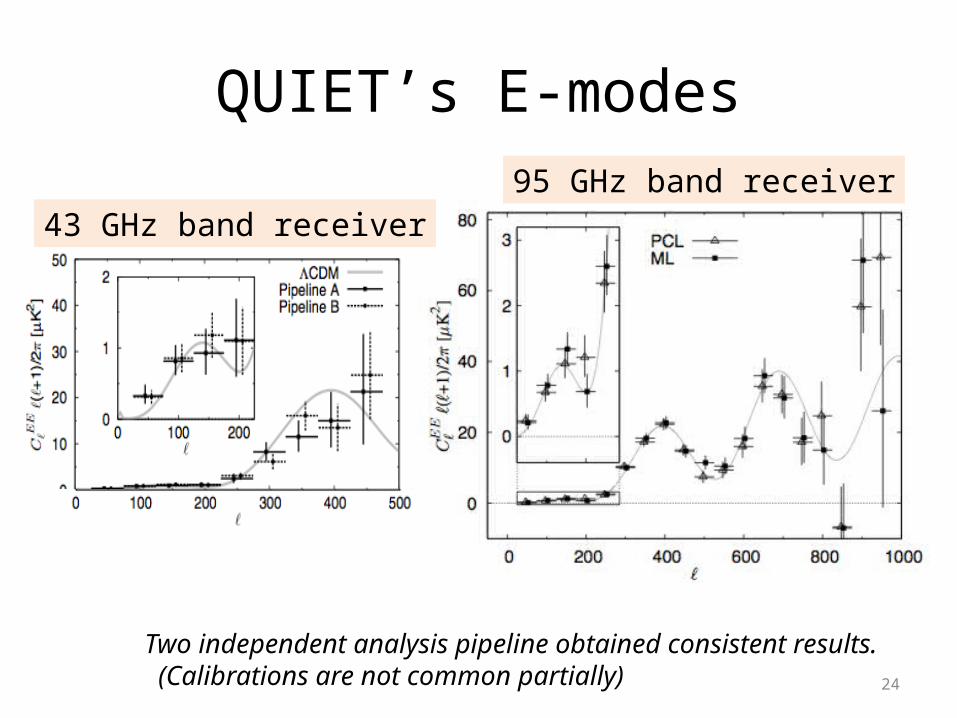
QUIET’s E-modes
24
Two independent analysis pipeline obtained consistent results. (Calibrations are not common partially)
43 GHz band receiver95 GHz band receiver
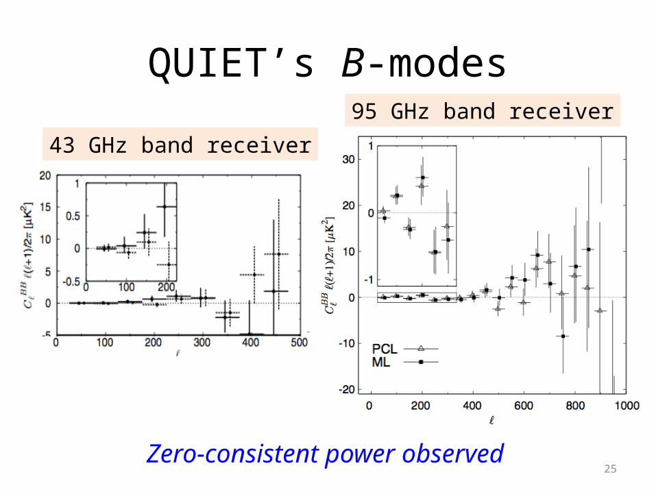
QUIET’s B-modes
25
43 GHz band receiver
95 GHz band receiver
Zero-consistent power observed
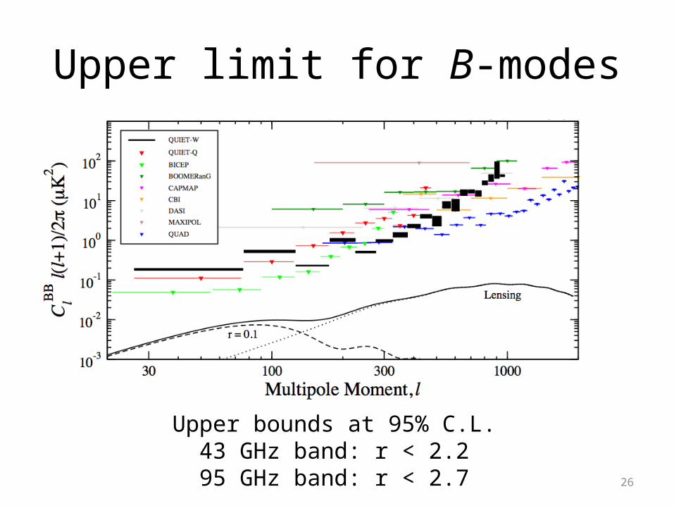
Upper limit for B-modes
Upper bounds at 95% C.L. 43 GHz band: r < 2.2 95 GHz band: r < 2.7 26
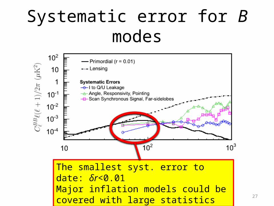
Systematic error for B modes
The smallest syst. error to date: δr<0.01Major inflation models could be covered with large statistics
27
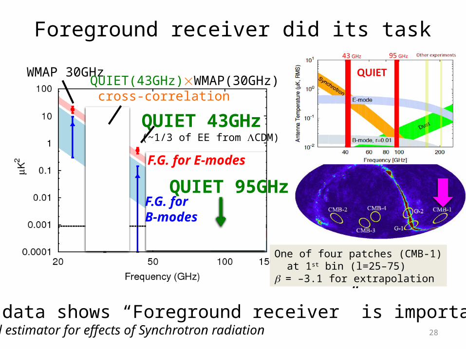
Real data shows “Foreground receiver” is important !!Good estimator for effects of Synchrotron radiation 28
WMAP 30GHz
QUIET 43GHz(~1/3 of EE from LCDM)
One of four patches (CMB-1) at 1st bin (l=25–75) b = –3.1 for extrapolation
Foreground receiver did its task
r = 0.02
F.G. for E-modes
F.G. forB-modes
QUIET(43GHz)WMAP(30GHz) cross-correlation
QUIET 95GHz
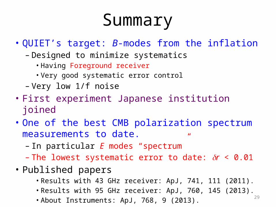
Summary• QUIET’s target: B-modes from the inflation
– Designed to minimize systematics• Having Foreground receiver• Very good systematic error control
– Very low 1/f noise
• First experiment Japanese institution joined• One of the best CMB polarization spectrum
measurements to date. – In particular E modes “spectrum”– The lowest systematic error to date: dr < 0.01
• Published papers• Results with 43 GHz receiver: ApJ, 741, 111 (2011).• Results with 95 GHz receiver: ApJ, 760, 145 (2013).• About Instruments: ApJ, 768, 9 (2013). 29
30
Referee report for 95 GHz receiver results
Let me congratulate the QUIET team for this impressive piece of work! The control of all systematics down to r of 0.01 is absolutely spectacular. I found the paper clearly written, and a model for future polarization based CMB papers…