Embed Size (px)
Citation preview
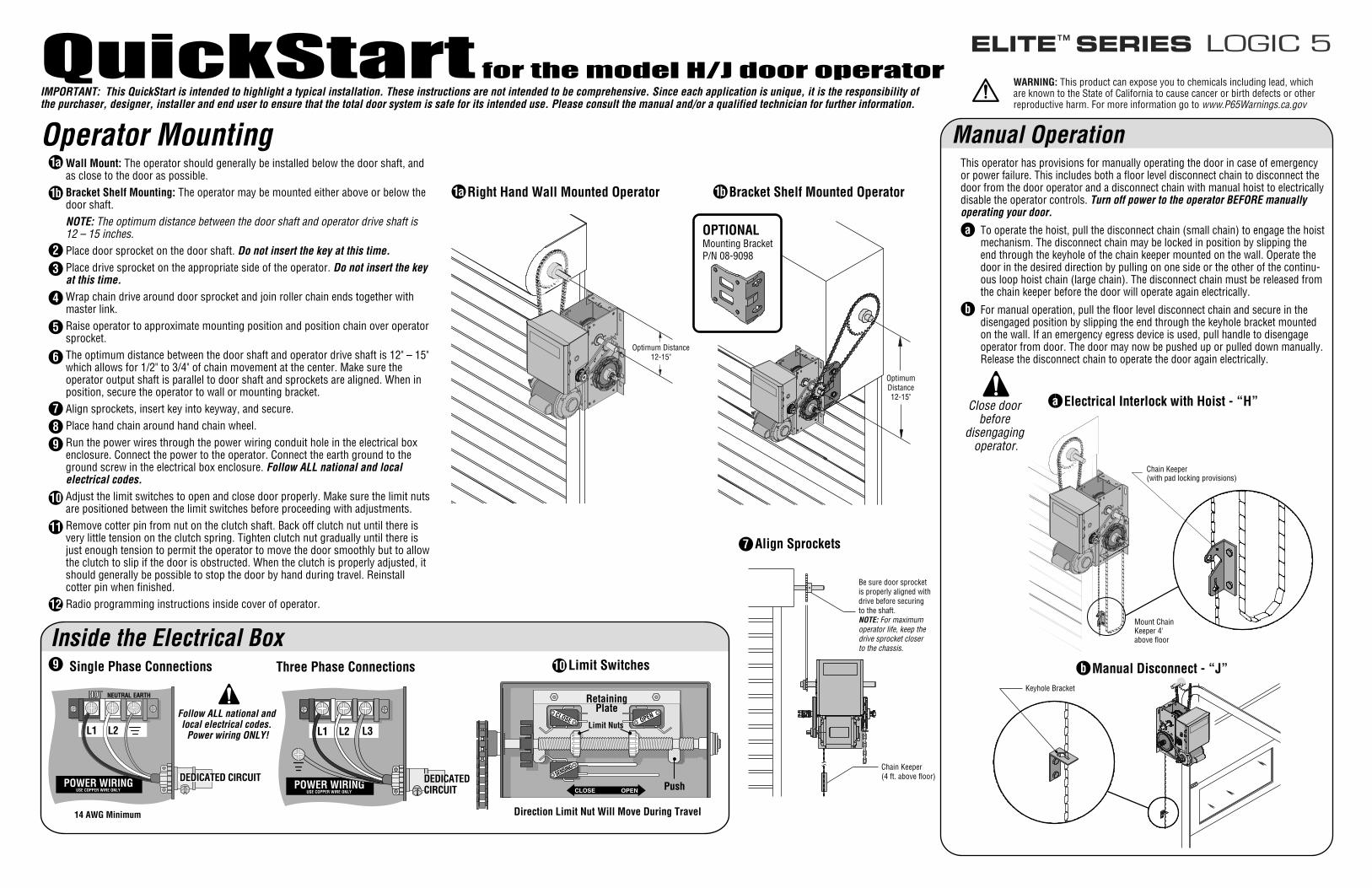
Operator MountingWall Mount: The operator should generally be installed below the door shaft, and as close to the door as possible.Bracket Shelf Mounting: The operator may be mounted either above or below the door shaft.NOTE: The optimum distance between the door shaft and operator drive shaft is 12 – 15 inches.Place door sprocket on the door shaft. Do not insert the key at this time.
Place drive sprocket on the appropriate side of the operator. Do not insert the key at this time.
Wrap chain drive around door sprocket and join roller chain ends together with master link.Raise operator to approximate mounting position and position chain over operator sprocket.The optimum distance between the door shaft and operator drive shaft is 12" – 15" which allows for 1/2" to 3/4" of chain movement at the center. Make sure the operator output shaft is parallel to door shaft and sprockets are aligned. When in position, secure the operator to wall or mounting bracket.Align sprockets, insert key into keyway, and secure.Place hand chain around hand chain wheel.Run the power wires through the power wiring conduit hole in the electrical box enclosure. Connect the power to the operator. Connect the earth ground to the ground screw in the electrical box enclosure. Follow ALL national and local electrical codes.
Adjust the limit switches to open and close door properly. Make sure the limit nuts are positioned between the limit switches before proceeding with adjustments.Remove cotter pin from nut on the clutch shaft. Back off clutch nut until there is very little tension on the clutch spring. Tighten clutch nut gradually until there is just enough tension to permit the operator to move the door smoothly but to allow the clutch to slip if the door is obstructed. When the clutch is properly adjusted, it should generally be possible to stop the door by hand during travel. Reinstall cotter pin when finished.Radio programming instructions inside cover of operator.
1b
1a
23
4
5
6
789
10
11
12
IMPORTANT: This QuickStart is intended to highlight a typical installation. These instructions are not intended to be comprehensive. Since each application is unique, it is the responsibility of the purchaser, designer, installer and end user to ensure that the total door system is safe for its intended use. Please consult the manual and/or a qualified technician for further information.
Align Sprockets7
Inside the Electrical BoxLimit Switches10
CLOSE OPEN
SENSING
Direction Limit Nut Will Move During Travel
RetainingPlate
Push
Limit Nuts
Single Phase Connections9
Follow ALL national and local electrical codes.
Power wiring ONLY!
Close door before
disengaging operator.
OPTIONALMounting BracketP/N 08-9098
OptimumDistance12-15"
Be sure door sprocket is properly aligned with drive before securing to the shaft.NOTE: For maximum operator life, keep the drive sprocket closer to the chassis.
Chain Keeper(4 ft. above floor)
Optimum Distance12-15"
Right Hand Wall Mounted Operator1a Bracket Shelf Mounted Operator1b
Keyhole Bracket
Mount ChainKeeper 4'above floor
Chain Keeper(with pad locking provisions)
a
b
This operator has provisions for manually operating the door in case of emergency or power failure. This includes both a floor level disconnect chain to disconnect the door from the door operator and a disconnect chain with manual hoist to electrically disable the operator controls. Turn off power to the operator BEFORE manually operating your door.
To operate the hoist, pull the disconnect chain (small chain) to engage the hoist mechanism. The disconnect chain may be locked in position by slipping the end through the keyhole of the chain keeper mounted on the wall. Operate the door in the desired direction by pulling on one side or the other of the continu-ous loop hoist chain (large chain). The disconnect chain must be released from the chain keeper before the door will operate again electrically.
For manual operation, pull the floor level disconnect chain and secure in the disengaged position by slipping the end through the keyhole bracket mounted on the wall. If an emergency egress device is used, pull handle to disengage operator from door. The door may now be pushed up or pulled down manually. Release the disconnect chain to operate the door again electrically.
Manual Operation
Manual Disconnect - “J”b
Electrical Interlock with Hoist - “H”a
QuickStart for the model H/J door operator LOGIC 5
POWER WIRINGUSE COPPER WIRE ONLY
L1 L2
14 AWG Minimum
HOT NEUTRAL EARTH
DEDICATED CIRCUITPOWER WIRING
USE COPPER WIRE ONLY
L1 L2
DEDICATED CIRCUIT
Three Phase Connections
L3
WARNING: This product can expose you to chemicals including lead, which are known to the State of California to cause cancer or birth defects or other reproductive harm. For more information go to www.P65Warnings.ca.gov
OPEN
CLOSE
STOP
Half
the
Heig
ht o
f the
Doo
r
NEVER run Control wiring in same conduit as the
Power wiring!
Edge Sensor
Appr
oxim
atel
y 5
Feet
6" max above the
floor.
White/BlackWhite
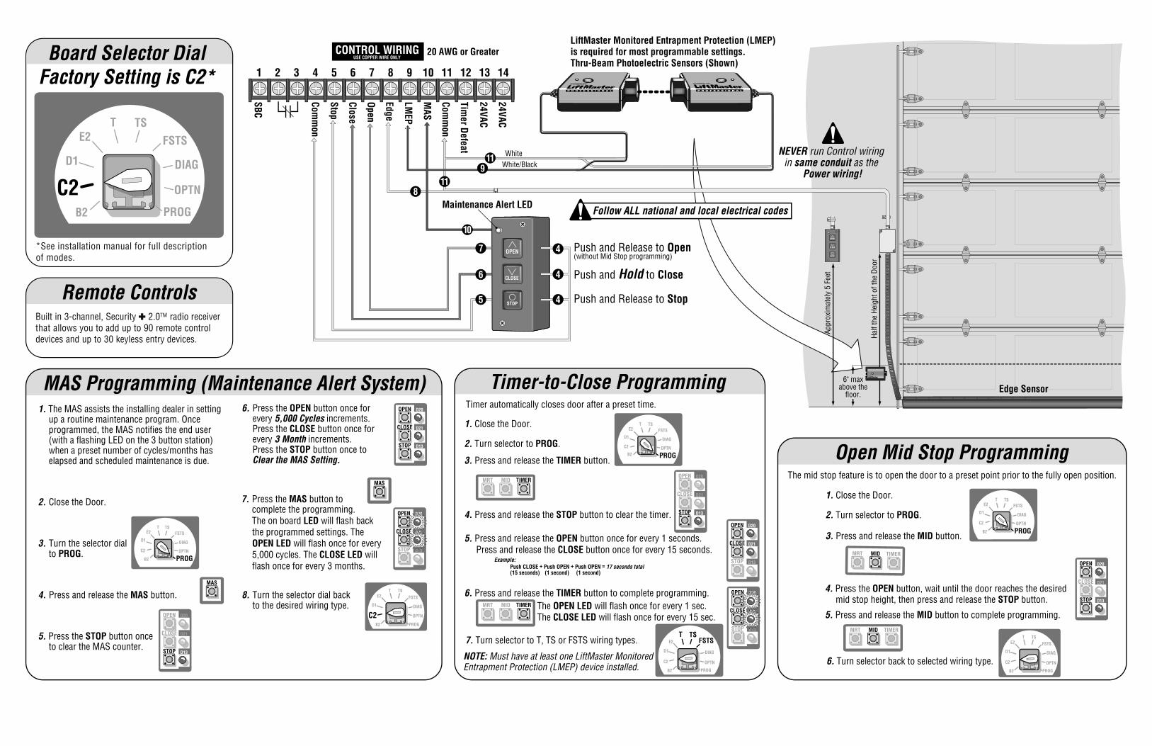
Push and Release to Open(without Mid Stop programming)
Push and Release to Stop
Push and Hold to Close
CONTROL WIRINGUSE COPPER WIRE ONLY
TIMERMIDMRT
TIMERMIDMRT
E2T TS
FSTS
DIAG
PROG
D1
B2
C2
Open Mid Stop Programming
1. Close the Door.
6. Turn selector back to selected wiring type.
3. Press and release the MID button.
2. Turn selector to PROG.
OPEN
CLOSE
STOP
D20
D21
D13
11
119
8
20 AWG or Greater
24VAC
24VAC
Timer Defeat
Comm
on
MAS
Maintenance Alert LED
LMEP
Edge
Open
Close
Stop
Comm
on
SBC
141 2 3 4 5 6 7 8 9 10 11 12 13
7
6
5 4
4
4
10
The OPEN LED will flash once for every 1 sec.The CLOSE LED will flash once for every 15 sec.
Timer-to-Close ProgrammingTimer automatically closes door after a preset time.
1. Close the Door.
5. Press and release the OPEN button once for every 1 seconds. Press and release the CLOSE button once for every 15 seconds.
TIMERMIDMRT
3. Press and release the TIMER button.
TIMERMIDMRT
6. Press and release the TIMER button to complete programming.
2. Turn selector to PROG.
4. Press and release the STOP button to clear the timer.
OPEN
CLOSE
STOP
D20
D21
D13
Example:Push CLOSE + Push OPEN + Push OPEN = 17 seconds total(15 seconds) (1 second) (1 second)
OPEN
CLOSE
STOP
D20
D21
D13
The mid stop feature is to open the door to a preset point prior to the fully open position.
E2T TS
FSTS
DIAG
PROG
D1
B2
C2
8. Turn the selector dial back to the desired wiring type.
MAS Programming (Maintenance Alert System)
MAS
6. Press the OPEN button once for every 5,000 Cycles increments. Press the CLOSE button once for every 3 Month increments. Press the STOP button once to Clear the MAS Setting.
OPEN
CLOSE
STOP
D20
D21
D13
2. Close the Door.
1. The MAS assists the installing dealer in setting up a routine maintenance program. Once programmed, the MAS notifies the end user (with a flashing LED on the 3 button station) when a preset number of cycles/months has elapsed and scheduled maintenance is due.
4. Press and release the MAS button.
5. Press the STOP button once to clear the MAS counter.
3. Turn the selector dial to PROG.
MAS
OPEN
CLOSE
STOP
D20
D21
D13
OPEN
CLOSE
STOP
D20
D21
D13
OPEN
CLOSE
STOP
D20
D21
D13
7. Turn selector to T, TS or FSTS wiring types.
NOTE: Must have at least one LiftMaster Monitored Entrapment Protection (LMEP) device installed.
Follow ALL national and local electrical codes
OPTN
OPTN
LiftMaster Monitored Entrapment Protection (LMEP) is required for most programmable settings.Thru-Beam Photoelectric Sensors (Shown)
E2T TS
FSTS
DIAG
PROG
D1
B2
C2 OPTN
E2T TS
FSTSDIAG
PROG
D1
B2
C2 OPTN
E2T TS
FSTS
DIAG
PROG
D1
B2
C2 OPTN
E2T TS
FSTS
DIAG
PROG
D1
B2
C2 OPTN
4. Press the OPEN button, wait until the door reaches the desiredmid stop height, then press and release the STOP button.
5. Press and release the MID button to complete programming.
7. Press the MAS button to complete the programming. The on board LED will flash back the programmed settings. The OPEN LED will flash once for every 5,000 cycles. The CLOSE LED will flash once for every 3 months.
Remote ControlsBuilt in 3-channel, Security 2.0TM radio receiver that allows you to add up to 90 remote control devices and up to 30 keyless entry devices.
E2T TS
FSTS
DIAG
PROG
D1
C2B2
Factory Setting is C2*Board Selector Dial
OPTN
*See installation manual for full description of modes.
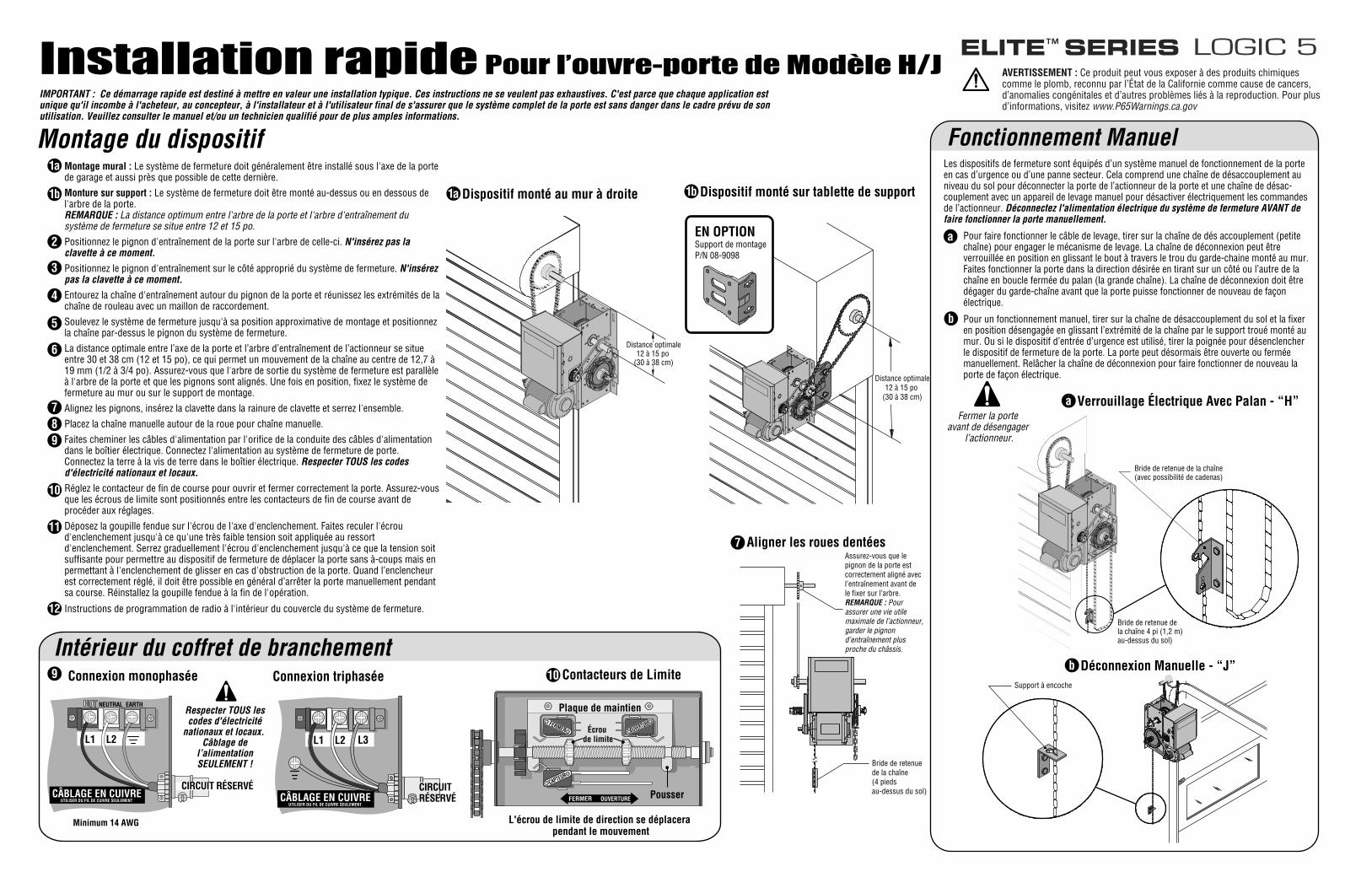
Montage du dispositifMontage mural : Le système de fermeture doit généralement être installé sous l'axe de la porte de garage et aussi près que possible de cette dernière.
Monture sur support : Le système de fermeture doit être monté au-dessus ou en dessous de l'arbre de la porte.REMARQUE : La distance optimum entre l'arbre de la porte et l'arbre d'entraînement du système de fermeture se situe entre 12 et 15 po.
Positionnez le pignon d'entraînement de la porte sur l'arbre de celle-ci. N'insérez pas la clavette à ce moment.
Positionnez le pignon d'entraînement sur le côté approprié du système de fermeture. N'insérez pas la clavette à ce moment.
Entourez la chaîne d'entraînement autour du pignon de la porte et réunissez les extrémités de la chaîne de rouleau avec un maillon de raccordement.
Soulevez le système de fermeture jusqu'à sa position approximative de montage et positionnez la chaîne par-dessus le pignon du système de fermeture.
La distance optimale entre l’axe de la porte et l’arbre d’entraînement de l’actionneur se situe entre 30 et 38 cm (12 et 15 po), ce qui permet un mouvement de la chaîne au centre de 12,7 à 19 mm (1/2 à 3/4 po). Assurez-vous que l'arbre de sortie du système de fermeture est parallèle à l'arbre de la porte et que les pignons sont alignés. Une fois en position, fixez le système de fermeture au mur ou sur le support de montage.
Alignez les pignons, insérez la clavette dans la rainure de clavette et serrez l'ensemble.
Placez la chaîne manuelle autour de la roue pour chaîne manuelle.
Faites cheminer les câbles d'alimentation par l'orifice de la conduite des câbles d'alimentation dans le boîtier électrique. Connectez l'alimentation au système de fermeture de porte. Connectez la terre à la vis de terre dans le boîtier électrique. Respecter TOUS les codes d'électricité nationaux et locaux.
Réglez le contacteur de fin de course pour ouvrir et fermer correctement la porte. Assurez-vous que les écrous de limite sont positionnés entre les contacteurs de fin de course avant de procéder aux réglages.
Déposez la goupille fendue sur l'écrou de l'axe d'enclenchement. Faites reculer l'écrou d'enclenchement jusqu'à ce qu'une très faible tension soit appliquée au ressort d'enclenchement. Serrez graduellement l'écrou d'enclenchement jusqu'à ce que la tension soit suffisante pour permettre au dispositif de fermeture de déplacer la porte sans à-coups mais en permettant à l'enclenchement de glisser en cas d'obstruction de la porte. Quand l’enclencheur est correctement réglé, il doit être possible en général d’arrêter la porte manuellement pendant sa course. Réinstallez la goupille fendue à la fin de l'opération.
Instructions de programmation de radio à l'intérieur du couvercle du système de fermeture.
1b
1a
2
3
4
5
6
789
10
11
12
IMPORTANT : Ce démarrage rapide est destiné à mettre en valeur une installation typique. Ces instructions ne se veulent pas exhaustives. C'est parce que chaque application estunique qu'il incombe à l'acheteur, au concepteur, à l'installateur et à l'utilisateur final de s'assurer que le système complet de la porte est sans danger dans le cadre prévu de sonutilisation. Veuillez consulter le manuel et/ou un technicien qualifié pour de plus amples informations.
Aligner les roues dentées7
Intérieur du coffret de branchementContacteurs de Limite10
FERMER OUVERTURE
CAPTEUR
L'écrou de limite de direction se déplacera pendant le mouvement
Plaque de maintien
Pousser
Écrou de limite
Connexion monophasée9
Respecter TOUS lescodes d'électricité
nationaux et locaux. Câblage de
l’alimentationSEULEMENT !
Fermer la porte avant de désengager
l’actionneur.
EN OPTIONSupport de montageP/N 08-9098
Distance optimale12 à 15 po
(30 à 38 cm)
Assurez-vous que le pignon de la porte est correctement aligné avec l’entraînement avant de le fixer sur l’arbre.REMARQUE : Pour assurer une vie utile maximale de l’actionneur, garder le pignon d’entraînement plus proche du châssis.
Bride de retenuede la chaîne(4 pieds au-dessus du sol)
Distance optimale12 à 15 po
(30 à 38 cm)
Dispositif monté au mur à droite1a Dispositif monté sur tablette de support1b
Support à encoche
Bride de retenue dela chaîne 4 pi (1,2 m)au-dessus du sol)
Bride de retenue de la chaîne(avec possibilité de cadenas)
a
b
Les dispositifs de fermeture sont équipés d’un système manuel de fonctionnement de la porte en cas d’urgence ou d’une panne secteur. Cela comprend une chaîne de désaccouplement au niveau du sol pour déconnecter la porte de l’actionneur de la porte et une chaîne de désac-couplement avec un appareil de levage manuel pour désactiver électriquement les commandes de l’actionneur. Déconnectez l'alimentation électrique du système de fermeture AVANT de faire fonctionner la porte manuellement.
Pour faire fonctionner le câble de levage, tirer sur la chaîne de dés accouplement (petite chaîne) pour engager le mécanisme de levage. La chaîne de déconnexion peut être verrouillée en position en glissant le bout à travers le trou du garde-chaine monté au mur. Faites fonctionner la porte dans la direction désirée en tirant sur un côté ou l’autre de la chaîne en boucle fermée du palan (la grande chaîne). La chaîne de déconnexion doit être dégager du garde-chaîne avant que la porte puisse fonctionner de nouveau de façon électrique.
Pour un fonctionnement manuel, tirer sur la chaîne de désaccouplement du sol et la fixer en position désengagée en glissant l’extrémité de la chaîne par le support troué monté au mur. Ou si le dispositif d’entrée d’urgence est utilisé, tirer la poignée pour désenclencher le dispositif de fermeture de la porte. La porte peut désormais être ouverte ou fermée manuellement. Relâcher la chaîne de déconnexion pour faire fonctionner de nouveau la porte de façon électrique.
Fonctionnement Manuel
Déconnexion Manuelle - “J”b
Verrouillage Électrique Avec Palan - “H”a
Installation rapide Pour l’ouvre-porte de Modèle H/JLOGIC 5
CÂBLAGE EN CUIVREUTILISER DU FIL DE CUIVRE SEULEMENT
L1 L2
Minimum 14 AWG
HOT NEUTRAL EARTH
CIRCUIT RÉSERVÉCÂBLAGE EN CUIVRE
UTILISER DU FIL DE CUIVRE SEULEMENT
L1 L2
CIRCUIT RÉSERVÉ
Connexion triphasée
L3
OUVERTUREFERMER
AVERTISSEMENT : Ce produit peut vous exposer à des produits chimiques comme le plomb, reconnu par l’État de la Californie comme cause de cancers, d’anomalies congénitales et d’autres problèmes liés à la reproduction. Pour plus d’informations, visitez www.P65Warnings.ca.gov
La m
oitié
de
la h
aute
ur d
ela
por
te d
e ga
rage
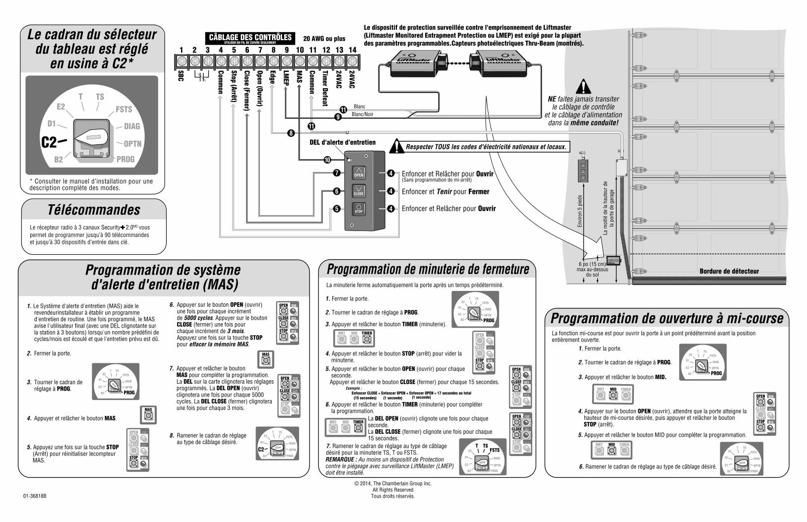
NE faites jamais transiterle câblage de contrôle
et le câblage d’alimentationdans la même conduite!
Bordure de détecteur
Envi
ron
5 pi
eds
Blanc/NoirBlanc
Enfoncer et Relâcher pour Ouvrir(Sans programmation de mi-arrêt)
Enfoncer et Relâcher pour Ouvrir
Enfoncer et Tenir pour Fermer
CÂBLAGE DES CONTRÔLESUTILISER DU FIL DE CUIVRE SEULEMENT
E2T TS
FSTS
DIAG
PROG
D1
C2B2
Le cadran du sélecteurdu tableau est réglé
en usine à C2*
TIMERMIDMRT
TIMERMIDMRT
E2T TS
FSTS
DIAG
PROG
D1
B2
C2
Programmation de ouverture à mi-course
1. Fermer la porte.
6. Ramener le cadran de réglage au type de câblage désiré.
3. Appuyer et relâcher le bouton MID.
2. Tourner le cadran de réglage à PROG.
OPEN
CLOSE
STOP
D20
D21
D13
20 AWG ou plus
24VAC
24VAC
Timer Defeat
Comm
on
MAS
DEL d'alerte d'entretien
LMEP
Edge
Open (Ouvrir)
Close (Fermer)
Stop (Arrêt)
Comm
on
SBC
141 2 3 4 5 6 7 8 9 10 11 12 13
La DEL OPEN (ouvrir) clignote une fois pour chaque seconde.La DEL CLOSE (fermer) clignote une fois pour chaque 15 secondes.
Programmation de minuterie de fermetureLa minuterie ferme automatiquement la porte après un temps prédéterminé.
1. Fermer la porte.
5. Appuyer et relâcher le bouton OPEN (ouvrir) pour chaque seconde. Appuyer et relâcher le bouton CLOSE (fermer) pour chaque 15 secondes.
TIMERMIDMRT
3. Appuyer et relâcher le bouton TIMER (minuterie).
TIMERMIDMRT
6. Appuyer et relâcher le bouton TIMER (minuterie) pour compléter la programmation.
2. Tourner le cadran de réglage à PROG.
4. Appuyer et relâcher le bouton STOP (arrêt) pour vider la minuterie.
OPEN
CLOSE
STOP
D20
D21
D13
Exemple :Enfoncer CLOSE + Enfoncer OPEN + Enfoncer OPEN = 17 secondes au total
(15 secondes) (1 seconde) (1 seconde)
OPEN
CLOSE
STOP
D20
D21
D13
© 2014, The Chamberlain Group Inc.All Rights Reserved
Tous droits réservés.01-36818B
La fonction mi-course est pour ouvrir la porte à un point prédéterminé avant la position entièrement ouverte.
E2T TS
FSTS
DIAG
PROG
D1
B2
C2
8. Ramener le cadran de réglage au type de câblage désiré.
Programmation de système d'alerte d'entretien (MAS)
MAS
6. Appuyer sur le bouton OPEN (ouvrir) une fois pour chaque incrément de 5000 cycles. Appuyer sur le bouton CLOSE (fermer) une fois pour chaque incrément de 3 mois. Appuyez une fois sur la touche STOP pour effacer la mémoire MAS.
OPEN
CLOSE
STOP
D20
D21
D13
2. Fermer la porte.
1. Le Système d'alerte d'entretien (MAS) aide le revendeurinstallateur à établir un programme d'entretien de routine. Une fois programmé, le MAS avise l'utilisateur final (avec une DEL clignotante sur la station à 3 boutons) lorsqu'un nombre prédéfini de cycles/mois est écoulé et que l'entretien prévu est dû.
4. Appuyer et relâcher le bouton MAS.
5. Appuyez une fois sur la touche STOP (Arrêt) pour réinitialiser lecompteur MAS.
3. Tourner le cadran de réglage à PROG.
MAS
OPEN
CLOSE
STOP
D20
D21
D13
OPEN
CLOSE
STOP
D20
D21
D13
OPEN
CLOSE
STOP
D20
D21
D13
7. Ramener le cadran de réglage au type de câblagedésiré pour la minuterie TS, T ou FSTS.REMARQUE : Au moins un dispositif de Protection contre le piégeage avec surveillance LiftMaster (LMEP) doit être installé.
Respecter TOUS les codes d'électricité nationaux et locaux.
OPTN
OPTN
OPTN
Le dispositif de protection surveillée contre l'emprisonnement de Liftmaster (Liftmaster Monitored Entrapment Protection ou LMEP) est exigé pour la plupart des paramètres programmables.Capteurs photoélectriques Thru-Beam (montrés).
E2T TS
FSTS
DIAG
PROG
D1
B2
C2 OPTN
E2T TS
FSTSDIAG
PROG
D1
B2
C2 OPTN
E2T TS
FSTS
DIAG
PROG
D1
B2
C2 OPTN
E2T TS
FSTS
DIAG
PROG
D1
B2
C2 OPTN
4. Appuyer sur le bouton OPEN (ouvrir), attendre que la porte atteigne la hauteur de mi-course désirée, puis appuyer et relâcher le bouton STOP (arrêt).
5. Appuyer et relâcher le bouton MID pour compléter la programmation.
7. Appuyer et relâcher le bouton MAS pour compléter la programmation. La DEL sur la carte clignotera les réglages programmés. La DEL OPEN (ouvrir) clignotera une fois pour chaque 5000 cycles. La DEL CLOSE (fermer) clignotera une fois pour chaque 3 mois.
6 po (15 cm)max au-dessus
du sol
* Consulter le manuel d’installation pour une description complète des modes.
TélécommandesLe récepteur radio à 3 canaux Security 2.0MC vous
permet de programmer jusqu’à 90 télécommandes et jusqu’à 30 dispositifs d’entrée dans clé.