Embed Size (px)
Citation preview

QuickStart Guide, IDP 100
Version 2.0Part Number 093-0712-000 Rev. C

Copyright NoticeCopyright © 1998-2002 NetScreen Technologies, Inc. All rights reserved.
Copyright © 1998-2002 NetScreen Technologies, Inc. All rights reserved. NetScreen, NetScreen Technologies, and the NetScreen logo are registered trademarks of NetScreen Technologies, Inc. and NetScreen-5, NetScreen-5XP, NetScreen-10, NetScreen-25, NetScreen-50, NetScreen-100, NetScreen-204, NetScreen-208, NetScreen-500, NetScreen-1000, NetScreen 5200, NetScreen 5400, NetScreen-Global PRO, NetScreen-Global PRO Express, NetScreen-IDP 100, NetScreen-IDP 500, NetScreen-Remote, GigaScreen, and NetScreen ScreenOS are trademarks of NetScreen Technologies, Inc. All other trademarks and registered trademarks are the property of their respective companies.
Information in this document is subject to change without notice.
No part of this document may be reproduced or transmitted in any form or by any means, electronic or mechanical, for any purpose, without receiving written permission from NetScreen Technologies, Inc.
NetScreen Technologies, Inc.350 Oakmead ParkwaySunnyvale, CA 94085 U.S.A.www.netscreen.com
General InformationToll Free: 877-NETSCREEN, [email protected] SupportToll Free: 877-NETSCREEN, [email protected]

QuickStart Guide 2.0, IDP 100 3
Contents
Getting Acquainted with IDP. . . . . . . . . . . . . . . . . . . . . . . . . . . . . . . . . . . 4
Overview. . . . . . . . . . . . . . . . . . . . . . . . . . . . . . . . . . . . . . . . . . . . . . . . . . 5
Step 1: Choosing a Deployment Mode . . . . . . . . . . . . . . . . . . . . . . . . . . . 6
Step 2: Installing the IDP Management Server . . . . . . . . . . . . . . . . . . . . 11
Step 3: Connecting to the IDP Appliance . . . . . . . . . . . . . . . . . . . . . . . . 13
Step 4: Configuring the IDP Sensor. . . . . . . . . . . . . . . . . . . . . . . . . . . . . 16
Step 5: Connecting IDP to Your Network. . . . . . . . . . . . . . . . . . . . . . . . . 17
Step 6: Installing the User Interface. . . . . . . . . . . . . . . . . . . . . . . . . . . . . 18
Step 7: Adding Network Components . . . . . . . . . . . . . . . . . . . . . . . . . . . 20
Step 8: Installing a Security Policy. . . . . . . . . . . . . . . . . . . . . . . . . . . . . . 21
Installation Notes . . . . . . . . . . . . . . . . . . . . . . . . . . . . . . . . . . . . . . . . . . 23
IDP QuickSheet . . . . . . . . . . . . . . . . . . . . . . . . . . . . . . . . . . . . . . . . . . . 24

4 NetScreen Technologies, Inc.
Getting Acquainted with IDPIDP Sensor Package ContentsIncluded in each NetScreen Sensor package you should find the following:
• IDP appliance• A bezel• An accessory box containing:
• 1 North American power cable• 2 Ethernet cables (blue cables)• 2 Crossover Ethernet cables (orange cables)• 1 Null modem Serial cable (beige cable)
• A documentation box containing:• Hardware Information Guide• Product data sheet• IDP Implementation Guide 2.0• IDP Release Notes 2.0
IDP Management Package ContentsIncluded in each NetScreen Management package you should find the following:
• NetScreen IDP Installation CD• IDP QuickStart Guide 2.0, IDP 100• IDP High Availability QuickStart 2.0, IDP 100• IDP Release Notes 2.0

QuickStart Guide 2.0, IDP 100 5
OverviewThis booklet describes how to install version 2.0 of the IDP Intrusion Detection and Prevention system for non-high availability (HA) configurations that use IDP 100 appliances.
For instructions on installing HA configurations, please see the High Availability QuickStart Guide 2.0. For IDP upgrades, please contact customer support.
The installation process consists of eight steps:
Step 1: Determining where to place your IDP appliance in your networkIn this step, you choose a deployment mode for the IDP system.
Step 2: Installing the IDP Management Server softwareIn this step, you install the Management Server software.
Step 3: Connecting to IDP applianceIn this step, you connect your system to the IDP appliance using a serial or network connection.
Step 4: Configuring the IDP Sensor softwareIn this step, you configure the Sensor software that is pre-installed on the IDP appliance.
Step 5: Connecting the IDP appliance to your networkIn this step, you connect the IDP appliance to your network.
Step 6: Installing the NetScreen User Interface (UI)In this step, you install the UI.
Step 7: Adding the IDP Sensor as a Network ObjectIn this step, you add the IDP Sensor as a Network Object in the IDP system.
Step 8: Installing a Security PolicyIn this step, you install a Security Policy on the IDP Sensor.
The NetScreen IDP Installation CD includes the software required to install the IDP Management Server, the IDP Sensor, and the User Interface.

6 NetScreen Technologies, Inc.
Step 1: Choosing a Deployment ModeThe first step in setting up IDP on your network is to decide on a deployment mode. The tables on pages 7-10 illustrate the four deployment modes and their primary advantages and disadvantages.
IDP Deployment ModesFor configurations without high availability, you can deploy the IDP Sensor as an active gateway or as a passive sniffer.
Active GatewayActive Gateway modes take full advantage of IDP attack prevention capabilities and MultiMethod Detection mechanisms. Choose bridge, proxy-ARP, or router mode.
Passive SnifferTo use IDP as a passive IDS system without prevention capabilities, deploy IDP in passive sniffer mode to monitor and log network traffic. If the Sensor is attached to a network switch, you must configure the switch to mirror all of the traffic to that port.
NOTE: The IDP system defaults to sniffer mode.
Review the examples on the following pages to determine which deployment mode to use for your network. When you have chosen a deployment mode, proceed to “Installing the IDP Management Server” on page 11.
High Availability ConfigurationsIDP can also be deployed as a high availability solution to provide failover, either in a standalone configuration or using third-party hardware.
HA configurations are not described in this guide. For more information about NetScreen’s high availability solutions, please see the following documents on the NetScreen customer Support Web site at www.netscreen.com/support:
• High Availability QuickStart Guide 2.0, IDP 100• Configuring IDP for Standalone HA (Technical Note)• Configuring IDP for Third-Party HA (Technical Note)

QuickStart Guide 2.0, IDP 100 7
Example 1: Sniffer Mode
TABLE 1. Sniffer Mode Advantages and DisadvantagesAdvantages Disadvantages
• Seamless replacement of current IDS• Minimal network changes• Does not create an additional point-of-failure
gateway• Can monitor and log suspicious network activity
• Passive monitoring with limited prevention only
• Must use a hub or the span port of a switch
IDP Appliance
Server11.1.1.2
GW 1.1.1.1
Server21.1.1.3
GW 1.1.1.1
Server31.1.1.4
GW 1.1.1.1
Firewall
Internet
Hub orSwitch
Eth0 (Sniffing Interface)
Protected Network
Eth2 2.2.2.7(Management Interface)
Client 2.2.2.3
Management Server2.2.2.4
Client 2.2.2.5
Client withUI installed
2.2.2.6
Management Network
Client 2.2.2.2
Hub or Switch
straight-through cable
mirror port if this is a switch
1.1.1.1
2.2.2.1
8 NetScreen Technologies, Inc.
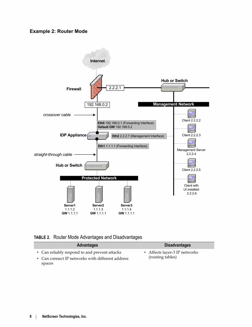
Example 2: Router Mode
TABLE 2. Router Mode Advantages and DisadvantagesAdvantages Disadvantages
• Can reliably respond to and prevent attacks• Can connect IP networks with different address
spaces
• Affects layer-3 IP networks (routing tables)
IDP Appliance
Server11.1.1.2
GW 1.1.1.1
Server21.1.1.3
GW 1.1.1.1
Server31.1.1.4
GW 1.1.1.1
Firewall
Internet
Hub or Switch
straight-through cable
Eth0 192.168.0.1 (Forwarding Interface)Default GW 192.168.0.2
Eth1 1.1.1.1 (Forwarding Interface)
Protected Network
crossover cable
Eth2 2.2.2.7 (Management Interface) Client 2.2.2.3
Management Server2.2.2.4
Client 2.2.2.5
Client withUI installed
2.2.2.6
Management Network
Client 2.2.2.2
Hub or Switch2.2.2.1
192.168.0.2

QuickStart Guide 2.0, IDP 100 9
Example 3: Bridge Mode
TABLE 3. Bridge Mode Advantages and DisadvantagesAdvantages Disadvantages
• Can reliably respond to and prevent attacks• Simple, transparent deployment• Allows layer-2 broadcasts (DHCP, etc.)• No changes to routing tables or network
equipment
IDP Appliance
Server11.1.1.2
GW 1.1.1.1
Server21.1.1.3
GW 1.1.1.1
Server31.1.1.4
GW 1.1.1.1
Firewall
Internet
Hub or Switch
straight-through cable
Eth0 no ip address (Forwarding Interface)
Eth1 no ip address (Forwarding Interface)
Protected Network
crossover cable
Eth2 2.2.2.7 (Management Interface) Client 2.2.2.3
Management Server2.2.2.4
Client 2.2.2.5
Client withUI installed
2.2.2.6
Management Network
Client 2.2.2.2
Hub or Switch2.2.2.1
1.1.1.1

10 NetScreen Technologies, Inc.
Example 4: Proxy-ARP Mode
When you have chosen a deployment mode for your IDP system, proceed to “Installing the IDP Management Server” on page 11.
TABLE 4. Proxy-ARP Mode Advantages and DisadvantagesAdvantages Disadvantages
• Can reliably respond to and prevent attacks• Simple, transparent deployment
• Network nodes may need to update cached ARP entries
IDP Appliance
Server11.1.1.2
GW 1.1.1.1
Server21.1.1.3
GW 1.1.1.1
Server31.1.1.4
GW 1.1.1.1
Firewall
Internet
Hub or Switch
straight-through cable
Eth0 192.168.0.1 (Forwarding Interface)
Eth1 1.1.1.5 (Forwarding Interface)
Protected Network
crossover cable
Eth2 2.2.2.7 (Management Interface) Client 2.2.2.3
Management Server2.2.2.4
Client 2.2.2.5
Client withUI installed
2.2.2.6
Management Network
Client 2.2.2.2
Hub or Switch2.2.2.1
1.1.1.1

QuickStart Guide 2.0, IDP 100 11
Step 2: Installing the IDP Management ServerIn this step, you install the IDP Management Server. You can install the Management Server software on the IDP appliance OR on any secure and trusted Red Hat Linux 7.2 or Solaris 7/8 computer.
Option 1: Install the Management Server on the IDP ApplianceFor simple networking environments, such as a small office or home office, you can install the Management Server directly on the IDP appliance. This configuration is often easier to install, but can negatively impact Sensor performance if multiple Sensors are in use.
IF YOU CHOOSE TO INSTALL THE MANAGMENT SERVER ON THE IDP APPLIANCE, PROCEED DIRECTLY TO STEP 3 ON PAGE 13. DO NOT USE THE INSTRUCTIONS BELOW.
Option 2: Install the Management Server on a separate computerIf you are using multiple Sensors or are operating in a production environment, NetScreen strongly recommends that you install the Management Server software on another machine attached to the network the Sensors are protecting.
If you install the Management Server on a remote system, you must authenticate the communication between the Management Server and the Sensor during the Sensor configuration process by providing IP address of the Management Server computer. For quick reference, write down the Management Server IP address in the table below:
Follow the instructions below to install the Management Server on a remote system.
To install the Management Server on a remote system:
NOTE: The Management Server installation process is case-sensitive. You must follow the menu selections exactly as shown in the script help text.
1. Ensure that the computer you are installing the Management Server on is:• Plugged in to a power source and powered on• Connected to a serial console or monitor and keyboard
Management Server IP Address

12 NetScreen Technologies, Inc.
• A secure and trusted Red Hat Linux 7.2 or Solaris 7/8 computer that is connected to your network
2. Insert the IDP Installation CD into the Management Server.Log in to the computer as root. If you are already logged in as a user other than root, become root by typing: su -
3. At the password prompt, enter the root password for the computer.4. Create an idp group with the user idp as the only member.
For Linux, type the command: useradd idpFor Solaris, type the commands:groupadd idpuseradd -g idp idp
5. Mount the IDP Installation CD following the operating system manufacturer’s instructions.
6. Change to the Management Server directory by using the cd command.For Linux: cd /mnt/cdrom/Mgt-Svr/LinuxFor Solaris: cd /cdrom/cdrom0/Mgt-Svr/Solaris
7. Run the Management Server install script by entering the appropriate command.For Linux: ./mgtsvr_linux_2_0.shFor Solaris: ./mgtsvr_solaris_2_0.shThe installation automatically begins.
8. When prompted, specify the directory IDP uses to store the Management Server data files.
9. When prompted, specify a password for the Management Server admin account. Confirm password.
NOTE: The admin account authenticates communication between the Management Server and the User Interface (UI). You are asked for this password again when you log in to the UI in “Installing the User Interface” on page 18.
The installation proceeds automatically. Several messages display to confirm the installation progress. After the installation is complete, the Management Server processes automatically start.
When you have successfully installed the Management Server, proceed to “Connecting to the IDP Appliance” on page 13.

QuickStart Guide 2.0, IDP 100 13
Step 3: Connecting to the IDP ApplianceIn this step, you connect to the IDP appliance and prepare to configure the Sensor software that is installed on it. You can connect to the IDP appliance using one of the methods shown below:
• Option 1: A standalone computer, such as a laptop, connected to the IDP appliance eth2 port.In this method, you change the IP address of a standalone computer to an IP address that is on the 192.168.1.1/24 network. Then, you connect that standalone computer to the IDP appliance and use the default settings for ethernet access to configure the Sensor software.
• Option 2: A serial console or keyboard and monitor connected to the IDP appliance.In this method, you assign the IDP appliance an IP address that is on your network. First, you connect a serial console or keyboard and monitor to the IDP appliance and configure ethernet access by choosing an ethernet port, IP address, and default route. Then, after you have configured ethernet access, you connect the IDP appliance to your network and configure the Sensor software from a computer on your network.
Choose an option and follow the appropriate instructions below. When you have established ethernet access to the IDP appliance, you can configure the Sensor software using the Appliance Configuration Manager (ACM), the Web-based IDP configuration tool. The configuration process is described in “Configuring the IDP Sensor” on page 16.
Use the illustration below to locate the IDP appliance ethernet and serial ports:
Power DB-15
Video Interface eth0eth1
KeyboardDB-9
Serial Interface eth2
eth3
IDP 100 Appliance Back Panel

14 NetScreen Technologies, Inc.
Option 1: Connect using a standalone computer
1. Connect a standalone computer, such as a laptop, to the IDP appliance eth2 port.To connect directly to the appliance, use a cross-over cable. To connect to the appliance over a hub or switch, use a straight-through cable.
2. Change the IP address of the standalone computer to 192.168.1.2. To change an IP address, see your computer’s operating system documentation.
3. On the connected computer, open a Web browser. The ACM supports Mozilla and IE 6.0 Web browsers.Enter the URL of the ACM wizard as https://192.168.1.1.
NOTE: Because the ACM uses HTTPS, you MUST enter https:// before the IP address.
4. Enter the default username and password as shown below:username: rootpassword: abc123The ACM wizard automatically displays. Proceed to “Configuring the IDP Sensor” on page 16.
Option 2: Connect using a serial console or keyboard and monitor
For serial console connections1. Connect a serial console to the IDP appliance serial port and configure the
terminal software to use parameters 9600, 8-None-1, hardware. For Windows, use HyperTerminal. For Linux, use minicom.Press Enter.
For keyboard and monitor connections1. Connect a keyboard and monitor to the IDP appliance.
For all connections2. Login to the IDP appliance using the information shown below:
login: rootpassword: abc123The ethernet configuration script automatically runs.
3. Follow the instructions in the script’s help text to configure ethernet access to the IDP appliance.• When prompted, enter the network card on the IDP appliance that you
want to use to configure the Sensor software. The current configuration (if any) of the specified network card displays.

QuickStart Guide 2.0, IDP 100 15
• When prompted, specify if you want to reconfigure the network card settings or accept the default configuration.
To reconfigure the current settings, type y . When prompted, assign an IP address to the network card and press Enter. Use an IP address that is reachable by the computer you will use to configure the Sensor software. When prompted, assign a network to the network card and press Enter.To accept the default settings, type n .
The current default route displays.• When prompted, specify if you want to assign a new route or accept the
default route.To assign a new default route, type y . When prompted, enter the default route for the computer that you will use to configure the Sensor software and press Enter.To accept the current default route, type n .
4. Use the ethernet port you chose in the configuration script to connect the IDP appliance to your network.To connect directly to another computer, use a cross-over cable. To connect to a hub or switch, use a straight-through cable.
5. Using the computer that is on your network, open a Web browser. The ACM supports Mozilla and IE 6.0 Web browsers.
6. Enter the IP address you chose in the configuration script.
NOTE: Because the ACM uses HTTPS, you MUST enter https:// before the IP address.
7. Enter the default username and password as shown below:username: rootpassword: abc123The ACM wizard automatically displays.
Proceed to “Configuring the IDP Sensor” on page 16.

16 NetScreen Technologies, Inc.
Step 4: Configuring the IDP SensorIn this step, you configure the IDP Sensor software that is pre-installed on the IDP appliance. Using the Appliance Configuration Manager (ACM), a Web-based software tool, you configure the IDP Sensor for your network.
Follow the on-screen instructions as the ACM wizard leads you through the six-section configuration process. To view the ACM online help, click the icon in the upper right corner. You can use your browser’s back button to return to previous page without loss of information.
NOTE: During the configuration process, you choose a One Time Password (OTP) and are given a VIN for your Sensor. Because you are prompted for this information again in Step 7: Adding Network Components, you might want to record the VIN.
The table below summarizes the information you should have available.
After you have saved and applied a configuration to the IDP Sensor, exit the ACM by closing the Web browser window. Proceed to “Connecting IDP to Your Network” on page 17.
TABLE 5. ACM configuration informationSection Configuration Information
Setup • IDP Sensor host and domain name• IDP Sensor root and admin passwords (default is abc123)• Management Server password for the User Interface
Mode • Deployment mode: sniffer, router, bridge, or proxy-ARP• Enable/choose high availability solution
Networking • Speed and duplex settings for IDP appliance interfaces• Management interface• Sniffer or gateway interfaces• Routing table
System • Enable/configure SSH • Enable/configure NTP• Enable/configure DNS• Set Time and Time Zone
Management • IP address of the Management Server for this Sensor and OTP• Sensor VIN_________________________________________ (case sensitive)• Install Management Server Locally (Optional)• Enable/configure ACM access
Confirmand Exit
View the current configuration and then:• Save all changes• Apply the configuration to the IDP appliance

QuickStart Guide 2.0, IDP 100 17
Step 5: Connecting IDP to Your NetworkIn this step, you reboot the IDP appliance and connect it to your network using the provided cables.
Rebooting the IDP ApplianceAfter you have configured the Sensor software, you must reboot the IDP appliance. Ensure that you are logged in to the Sensor as root, then, from the Sensor command line, type the following command: reboot;rebootYou can now disconnect the serial console, keyboard and monitor, or other standalone computer from the IDP appliance. If you changed the IP address of a standalone computer to access the ACM, be sure to change it back to its original IP address.
Connect the IDP appliance to your networkUsing the ethernet ports (interfaces), connect the IDP appliance to your network. An example configuration, showing ethernet ports and their intended connections, is shown below (your configuration may differ):
Use the following general guidelines to determine the appropriate cable. The necessary cables are included with the IDP system.
• To connect to a switch or hub, use the straight-through ethernet cable.• To connect to a firewall or router, use the crossover ethernet cable.
When you have successfully connected the IDP appliance to your network, proceed to “Installing the User Interface” on page 18.
to external networkto external network
to protected network to protected network
eth1 Forwarding Interface(optional)
eth0 Forwarding Interface(optional)
eth2 Forwarding Interfacecan also be the management interface
eth3 Forwarding Interface

18 NetScreen Technologies, Inc.
Step 6: Installing the User InterfaceIn this step, you install the User Interface (UI). The IDP Installation CD includes two versions of the UI installation. Follow the steps below for Windows or Red Hat Linux systems.
NOTE: The User Interface installation cannot be canceled from the initial install screen. You must click OK to reach the Introduction screen, then click Cancel to exit the installation.
To install the UI on a Windows client machine:1. Ensure that you are an Administrator user for the computer that you are
installing the UI on.For instructions on adding users to the Administrator group, please see your operating system manual.
2. Insert the IDP Installation CD into the CD drive of the client machine.If Autoplay is enabled, the installation starts automatically. If not, run the install application install.exe from your CD-ROM drive.
3. Follow the directions in the dialog boxes to install the UI.When prompted for the install set, choose Optimized for Windows to install a performance-enhanced version of the UI for Windows NT/2000/XP.
NOTE: If the computer you are installing the UI on has less than 256 MB of RAM, choose the install set Optimized for Memory Usage instead.
To install the UI on a Red Hat Linux client machine:1. Insert the IDP Installation CD into the CD drive of the client machine and
mount the CD following the manufacturer’s instructions.2. In a command shell, run ./install.bin from the /mnt/cdrom/UI/Linux
directory of your CD drive.
NOTE: For Linux systems other than Red Hat, run the install script from the appropriate mount directory.
3. Follow the directions in the dialog boxes to install the UI.When prompted for the install set, choose Optimized for Memory Usage to install the common application features.

QuickStart Guide 2.0, IDP 100 19
Opening the User Interface After Upgrading
When you open the User Interface for the first time after installing the UI, you must specify the following information to log in:
• Host Name. Use the name of your IDP Management Server.• User Name. Use the default user name admin.• Password. Use the password that you specified when you installed the
Management Server.
When you have installed the UI, proceed to “Adding Network Components” on page 20.

20 NetScreen Technologies, Inc.
Step 7: Adding Network ComponentsNetwork Objects represent the components of your network, such as individual host machines, servers, and subnets. You must add the IDP Sensor as a Network Object before the IDP system is functional. You can also create Network Objects for the network components you want to protect.
To add the IDP Sensor as a Network Object:1. Double-click the Object component in the Navigation Tree and select
Network Objects.2. Choose File>New Object from the menu bar to display the Select Object
Type dialog box. Click OK.3. Select Sensor and click OK to display the Sensor Editor. Enter the
information about the Sensor, including a unique name. Use the VIN and One Time Password from “Configuring the IDP Sensor” on page 16. If you are deploying IDP in gateway mode, click the Interfaces tab to specify the IDP appliance interfaces as internal or external. You can also add anti-spoofing information using the Anti-spoofing tab.
4. Click OK.5. From the toolbar, click to save the new IDP Sensor object to the IDP
system.The IDP Sensor Network Object is added to the Network Object database.
Adding Network Objects using OPSECIf you are running Check Point™ FireWall-1™ Next Generation (NG) on your network, you can automatically add FireWall-1 Network Objects to IDP using the OPSEC Object Importer. See the “Configuring OPSEC” chapter in the IDP Concepts Guide 2.0 for more information on importing objects with OPSEC.
When you have added the Sensor as a Network Object, proceed to “Installing a Security Policy” on page 21.

QuickStart Guide 2.0, IDP 100 21
Step 8: Installing a Security PolicyBefore the IDP system can begin protecting your network, you must install a Security Policy on the Sensor. You should also verify that the Sensor is correctly connected to your network by sending other types of traffic through the IDP appliance.
You can either use the default Security Policy created by NetScreen, or you can create a new, custom Security Policy for your network.
To install a Security Policy using a template1. Select the Security Policy component in the Navigation Tree and choose
File>New Policy from the menu bar.2. In the New Security Policy dialogue box, select Use Template and choose
the appropriate template from the pull-down menu.For IDP systems running in sniffer mode, choose sniffer_template.For IDP systems running in bridge, proxy-ARP, or router mode, choose inline_template.
NOTE: Alternatively, you can use the getting_started template, which is designed to help you fine-tune your IDP system in sniffer mode before you move it in-line. The IDP Implementation Guide walks you through using and customizing the getting-started template to your network.
3. Click OK. The selected Security Policy template displays.4. Customize the template to your network. You must specify the Sensor that
you want the Security Policy installed on.5. Choose Policy>Install from the menu bar to install the new Security Policy
on your Sensor. The Security Policy begins generating log records for security events immediately.
6. Open the Log Viewer component in the UI to ensure that you are receiving logs.
To verify Sensor connectivity• Ping through the IDP appliance: From a computer on the protected
network, ping the Management Server IP address. • Test connectivity to external networks: Use a computer on the protected
network to browse the Internet or send/receive email.

22 NetScreen Technologies, Inc.
Congratulations!You have successfully installed the NetScreen IDP system on your network.
Additional Resources• For further instructions on using your IDP system, use the IDP Online Help
in the NetScreen User Interface.• For more information about the IDP system, see the IDP Concepts Guide 2.0.• For detailed, step-by-step instructions on setting up and fine-tuning your
IDP system, see the IDP Implementation Guide 2.0.
Problems?If you experienced problems during this installation or have an installation issue you want to discuss, we strongly encourage you to contact NetScreen customer support at 1-877-NETSCREEN or [email protected].
For general information concerning known issues, IDP versions, and the IDP FAQ, please visit the NetScreen Support Web site at www.netscreen.com/support.

QuickStart Guide 2.0, IDP 100 23
Installation NotesUse this space to write down important information as you configure your IDP system.

24 NetScreen Technologies, Inc.
IDP QuickSheet
Usernames & Passwords
Sensor Login & Configure
username: rootpassword: abc123
Management Server Login
username: adminpassword: you set this password during Management Server configuration process
Appliance Configuration
Manager
URL https://192.168.1.1; this is also the default IP address of eth2, the management interface. Because the ACM uses HTTPS, you MUST enter https:// before the IP address.
Accessing To configure the Sensor, you must use a computer that is on the same network as the IDP appliance.
Management Server
Sniffer Recommended: install on the IDP applianceAlternative: install on a separate computer running Red Hat 7.2 or Solaris 7/8
Bridge, Router, Proxy-ARP
Recommended: install on a separate computer running Red Hat 7.2 or Solaris 7/8Alternative: install on the IDP appliance
Interfaces & IP Addresses
Management interface: default is eth2IP address: must be unique
Bridge, Router, Proxy-ARP
interface: any interface; can use multiple interfacesIP address: must be unique
eth2
eth3
eth0eth1
Keyboard
DB-9Serial Interface
DB-15Video Interface
Power
Use crossover cable to connect to a firewall or routerUse straight-through cable to connect to a hub or switchDefault management interface is eth2.