Embed Size (px)
Citation preview
01149/11 NAReplaces 01149/10
QuickSetter™ Balancingvalve with flow meter132 series
Product range
132 series Balancing valve with flow meter sizes 1/2”, 3/4”, 1”, 1 1/4”, 1 1/2”, and 2"
CALEFFIa aaa aaaaaaa aaaaaaaaaaD
5 3/4”5 3/4”6 1/4”6 1/2”6 3/4”
7”
C1 13/16”1 13/16”1 7/8”
2”2 1/4”2 1/2”
B3 5/16”3 5/16”3 3/8”3 1/2”3 5/8”3 3/4”
Weight (lb)2.01.82.42.83.44.4
A1/2”3/4”
1”1 1/4”1 1/2”
2”
Code132432A132552A132622A132772A132882A132992A
A B
CAD
CALEFFI
bar15
7
6
5
4
3
2
Dimensions
Technical specifications
MaterialsValveBody: brassBall: brassBall control stem: brass, chrome platedBall seal seat: PTFEControl stem guide: PSUSeals: EPDM
Flow meterBody: brassBypass valve stem: brass, chrome platedSprings: stainless steelSeals: EPDMFlow meter float and indicator cover: PSU
PerformanceSuitable Fluids: water, glycol solutionsMax. percentage of glycol: 50%Max. working pressure: 150 psi (10 bar)Working temperature range: 14 - 230°F (-10–110°C)Flow rate range unit of measurement: gpmAccuracy: ±10%Control stem angle of rotation: 90°Control stem adjustment wrench: 1/2”–1 1/4”: 9 mm
1 1/2” and 2": 12 mmThreaded connections: 1/2”– 2" FNPT
Flow rate correction factor: 20%-30% glycol solutions: 0.940%-50% glycol solutions: 0.8
InsulationMaterial: closed cell expanded PE-XThickness: 25/64 inch (10 mm)Density: - inner part: 1.9 lb/ft3 (30 kg/m3)
- outer part: 3.1 lb/ft3 (50 kg/m3)Thermal conductivity (DIN 52612):
- at 32°F (0°C): 0.263 BTU·in/hr·ft2·°F (0.038 W/(m·K))- at 104°F (40°C): 0.312 BTU·in/hr·ft2·°F (0.045 W/(m·K))
Coefficient of resistance to water vapor (DIN 52615): > 1,300Working temperature range: 32 - 212°F (0–100°C)Reaction to fire (DIN 4102): class B2
Flow rate ranges
ACCREDITED
ISO 9001 No. 0003ISO 9001 FM 21654
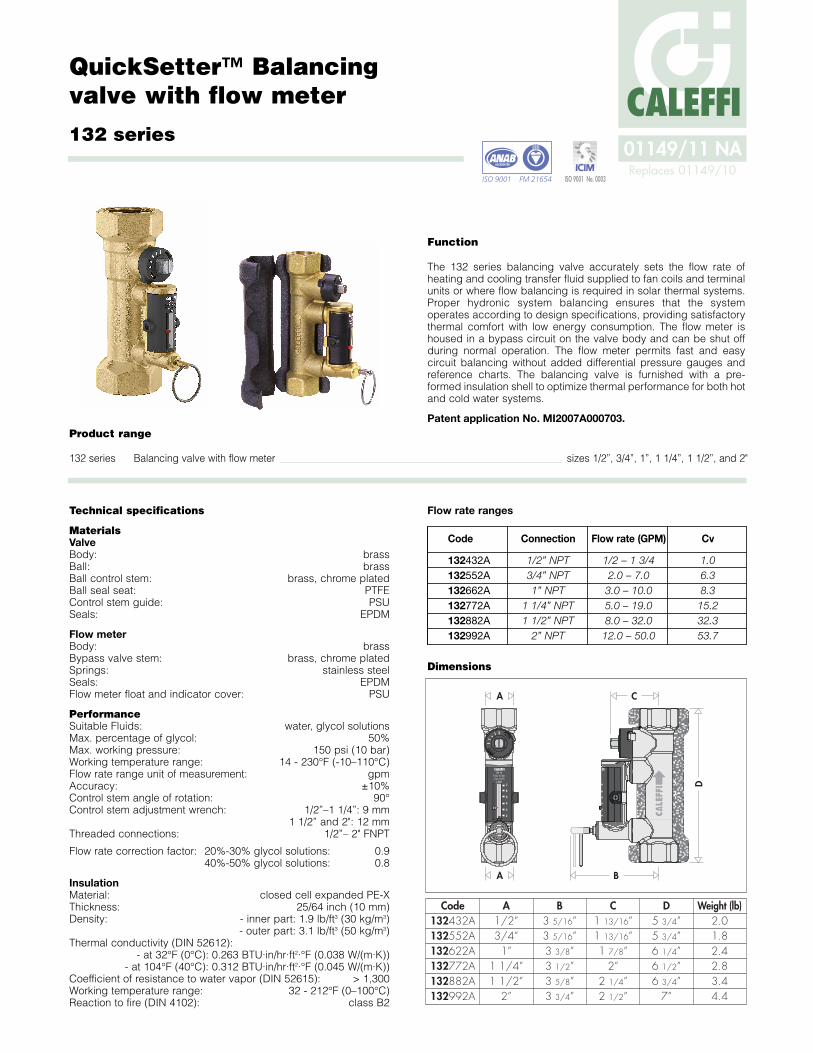
Function
The 132 series balancing valve accurately sets the flow rate ofheating and cooling transfer fluid supplied to fan coils and terminalunits or where flow balancing is required in solar thermal systems.Proper hydronic system balancing ensures that the systemoperates according to design specifications, providing satisfactorythermal comfort with low energy consumption. The flow meter ishoused in a bypass circuit on the valve body and can be shut offduring normal operation. The flow meter permits fast and easycircuit balancing without added differential pressure gauges andreference charts. The balancing valve is furnished with a pre-formed insulation shell to optimize thermal performance for both hotand cold water systems.
Patent application No. MI2007A000703.
Code Connection Flow rate (GPM) Cv
132432A 1/2” NPT 1/2 – 1 3/4 1.0132552A 3/4” NPT 2.0 – 7.0 6.3132662A 1” NPT 3.0 – 10.0 8.3132772A 1 1/4” NPT 5.0 – 19.0 15.2132882A 1 1/2” NPT 8.0 – 32.0 32.3132992A 2” NPT 12.0 – 50.0 53.7
Advantages of balanced circuits
Balanced circuits have the following principal benefits:
1. The system emitters operate properly in heating, cooling and dehumidification, saving energy and providing greater comfort.
2. The zone circuit pumps operate at maximum efficiency, reducing the risk of overheating and excessive wear.
3. High fluid velocities which can result in noise and abrasion are avoided.
4. The differential pressures acting on the circuit control valves are reduced preventing faulty operation.
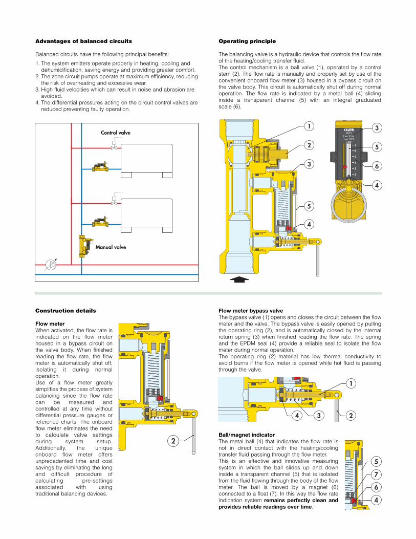
Operating principle
The balancing valve is a hydraulic device that controls the flow rateof the heating/cooling transfer fluid.The control mechanism is a ball valve (1), operated by a controlstem (2). The flow rate is manually and properly set by use of theconvenient onboard flow meter (3) housed in a bypass circuit onthe valve body. This circuit is automatically shut off during normaloperation. The flow rate is indicated by a metal ball (4) slidinginside a transparent channel (5) with an integral graduatedscale (6).
Construction details
Flow meterWhen activated, the flow rate isindicated on the flow meterhoused in a bypass circuit onthe valve body. When finishedreading the flow rate, the flowmeter is automatically shut off,isolating it during normaloperation.Use of a flow meter greatlysimplifies the process of systembalancing since the flow ratecan be measured andcontrolled at any time withoutdifferential pressure gauges orreference charts. The onboardflow meter eliminates the needto calculate valve settingsduring system setup.Additionally, the uniqueonboard flow meter offersunprecedented time and costsavings by eliminating the longand difficult procedure ofcalculating pre-settingsassociated with usingtraditional balancing devices.
Flow meter bypass valveThe bypass valve (1) opens and closes the circuit between the flowmeter and the valve. The bypass valve is easily opened by pullingthe operating ring (2), and is automatically closed by the internalreturn spring (3) when finished reading the flow rate. The springand the EPDM seal (4) provide a reliable seal to isolate the flowmeter during normal operation.The operating ring (2) material has low thermal conductivity toavoid burns if the flow meter is opened while hot fluid is passingthrough the valve.
Ball/magnet indicatorThe metal ball (4) that indicates the flow rate isnot in direct contact with the heating/coolingtransfer fluid passing through the flow meter.This is an effective and innovative measuringsystem in which the ball slides up and downinside a transparent channel (5) that is isolatedfrom the fluid flowing through the body of the flowmeter. The ball is moved by a magnet (6)connected to a float (7). In this way the flow rateindication system remains perfectly clean andprovides reliable readings over time.
Manual valve
Control valve
7 6 5 4 3 2
7 6 5 4 3 2
7
6
5
4
3
2
4
3
2
1
5
2
3
2
1
1
234
4
6
7
5
7
6
5
4
3
2
3
5
6
4
1
15
Flow rate adjustment
The flow rate is adjusted as follows:
Complete closing and opening of the valve
The valve can be completely closed and opened. A slot on thecontrol stem indicates the valve position. When the control stem isturned fully clockwise(the slot is perpendicularto the axis of the valve),the valve is fully closed(A). When the controlstem is turned fullycounter-clockwise (theslot is parallel to the axisof the valve), the valveis fully open (B).
Insulation
The 132 series balancing valveis supplied with a pre-formedinsulating shell. This systemensures perfect thermalinsulation and keeps out watervapor from the environment.Additionally, this type ofinsulation is ideal in cold watercircuits as it preventscondensation from forming onthe surface of the valve body.
100
0.1
1
0.2
0.3�
0.5�
200
500
∆p (psi) G
(l/h)
(gp
m)
10
2
3
5
20
0.1
1
0.2
0.3�
0.5�
(psi) (bar)
10
2
3
5
20
0.01
0.1
0.02
0.03�
0.05�
1.0
0.2
0.3
0.5
4
0.4� 0.4�
4
0.04�
0.4
1000
2000
5000
1000
0
2000
0
10.2
0.5
2 5 10 2 0 50 100
200
50
1/2”
3/4”
1” 1 1/
4”
1 1/
2”
2”
46.20
23.10
11.559.24
6.934.62
2.31
1.160.924
0.693
0.462
0.231
(feet of head)
7
6
5
4
3
2
7
6
5
4
3
2
CALEFFI
7
6
5
4
3
2
CALEFFI
7
6
5
4
3
2
765432
765432
7
6
5
4
3
2
7
6
5
4
3
2
CALEFFI
7
6
5
4
3
2
CALEFFI
7
6
5
4
3
2
765432
765432
7
6
5
4
3
2
7
6
5
4
3
2
CALEFFI
7
6
5
4
3
2
CALEFFI
7
6
5
4
3
2
765432
765432
7
6
5
4
3
2
7
6
5
4
3
2
CALEFFI
7
6
5
4
3
2
CALEFFI
7
6
5
4
3
2
765432
765432
132 series 132 series
5D
Pump
10D
A.With the aid of the flow rate indicator (1), mark the desired flow rate.
C.While holding the bypass valve open, use a wrench to turn thevalve control stem (4) to adjust the flow rate slowly. The resultingflow rate is indicated by the metal ball (5) that slides up and downinside a transparent channel (6) marked by a graduated scale in gpm.
D.Once the flow rate is properly adjusted, release the operating ring (2) of the bypass valve. The valve will automatically return to the closed position by means of an internal spring.
E. A replacement bypass valve stem (7) with operating ring is availablein event it is damaged and inoperable. Order code F19346.
A B
Completely closed Completely open
Installation
Install the balancing valve in a location that ensures free access tothe flow meter shutoff valve, control stem and flow rate indicator. Toensure accurate flow measurement, straight sections of pipeinstalled as shown is recommended.
The valve can be installed in any position with respect to the flowdirection shown on the valve body. Additionally, the valve can beinstalled either horizontally or vertically.
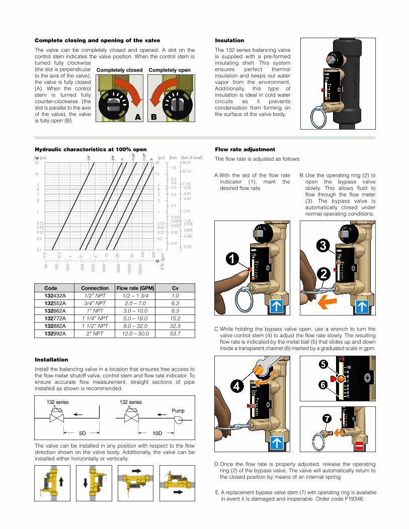
Hydraulic characteristics at 100% open
B.Use the operating ring (2) toopen the bypass valveslowly. This allows fluid toflow through the flow meter(3). The bypass valve isautomatically closed undernormal operating conditions.
Code Connection Flow rate (GPM) Cv132432A 1/2” NPT 1/2 – 1 3/4 1.0132552A 3/4” NPT 2.0 – 7.0 6.3132662A 1” NPT 3.0 – 10.0 8.3132772A 1 1/4” NPT 5.0 – 19.0 15.2132882A 1 1/2” NPT 8.0 – 32.0 32.3132992A 2” NPT 12.0 – 50.0 53.7

Application diagrams
The balancing valve with the flow meter should be installed on the circuit return pipe.
132 seriesBalancing valve with flow meter. Threaded connections 1/2”, 3/4", 1", 1-1/4", 1-1/2", 2" NPT Female by Female. Brass body. Brassball. Brass ball control stem, chrome plated. PTFE ball seal seat. PSU control stem guide. Brass flow meter body. Brass flow meterbypass valve stem, chrome plated. Stainless steel flow meter springs. PSU flow meter float and indicator cover. EPDM seals. Withpre-formed shell insulation in expanded closed cell PE-X. Water and glycol solutions. Maximum percentage of glycol 50%. Maximumworking pressure 150 psi (10 bar). Working temperature range 14 - 230 deg F (-10–110°C). Flow rate range unit of measurementgallons per minute (gpm). Accuracy ± 10%. Control stem angle of rotation 90°.
SPECIFICATION SUMMARIES
To adjust the flow rate to each riser
To adjust the flow rate to each emitter
To balance circuits serving air conditioning units
To balance zone branches in circuits with three-way valves
s
To balance the by-pass branch of outside compensatedcontrol circuits
We reserve the right to change our products and their relevant technical data, contained in this publication, at any time and without prior notice.
Caleffi North America, Inc.3883 West Milwaukee Road / Milwaukee, WI 53208
Tel: 414.238.2360 / Fax: 414.238.2366 / www.caleffi.us© Copyright 2011 Caleffi
CALEFFI