Embed Size (px)
Citation preview
QUICK2035
BGA Rework System
Operation Manual Thank you for purchasing our Rework System. The system is exclusively designed for reworking and soldering SMD component. Please carefully read this manual before operating the system. Store this manual in a safe, easily accessible place for future reference.
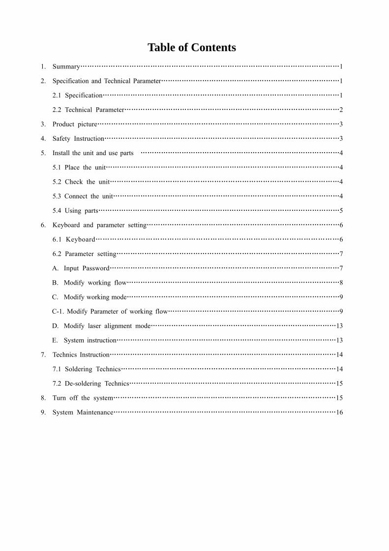
Table of Contents 1. Summary…………………………………………………………………………………………………1
2. Specification and Technical Parameter……………………………………………………………………1
2.1 Specification…………………………………………………………………………………………1
2.2 Technical Parameter…………………………………………………………………………………2
3. Product picture……………………………………………………………………………………………3
4. Safety Instruction…………………………………………………………………………………………3
5. Install the unit and use parts ……………………………………………………………………………4
5.1 Place the unit…………………………………………………………………………………………4
5.2 Check the unit………………………………………………………………………………………4
5.3 Connect the unit………………………………………………………………………………………4
5.4 Using parts……………………………………………………………………………………………5
6. Keyboard and parameter setting…………………………………………………………………………6
6.1 Keyboard…………………………………………………………………………………………6
6.2 Parameter setting……………………………………………………………………………………7
A. Input Password………………………………………………………………………………………7
B. Modify working flow…………………………………………………………………………………8
C. Modify working mode…………………………………………………………………………………9
C-1. Modify Parameter of working flow…………………………………………………………………9
D. Modify laser alignment mode………………………………………………………………………13
E. System instruction……………………………………………………………………………………13
7. Technics Instruction………………………………………………………………………………………14
7.1 Soldering Technics…………………………………………………………………………………14
7.2 De-soldering Technics………………………………………………………………………………15
8. Turn off the system……………………………………………………………………………………15
9. System Maintenance……………………………………………………………………………………16
OPERATION MANUAL
Page 1
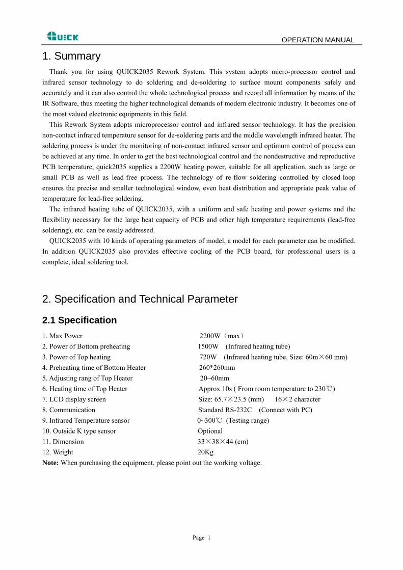
1. Summary Thank you for using QUICK2035 Rework System. This system adopts micro-processor control and
infrared sensor technology to do soldering and de-soldering to surface mount components safely and accurately and it can also control the whole technological process and record all information by means of the IR Software, thus meeting the higher technological demands of modern electronic industry. It becomes one of the most valued electronic equipments in this field.
This Rework System adopts microprocessor control and infrared sensor technology. It has the precision non-contact infrared temperature sensor for de-soldering parts and the middle wavelength infrared heater. The soldering process is under the monitoring of non-contact infrared sensor and optimum control of process can be achieved at any time. In order to get the best technological control and the nondestructive and reproductive PCB temperature, quick2035 supplies a 2200W heating power, suitable for all application, such as large or small PCB as well as lead-free process. The technology of re-flow soldering controlled by closed-loop ensures the precise and smaller technological window, even heat distribution and appropriate peak value of temperature for lead-free soldering.
The infrared heating tube of QUICK2035, with a uniform and safe heating and power systems and the flexibility necessary for the large heat capacity of PCB and other high temperature requirements (lead-free soldering), etc. can be easily addressed.
QUICK2035 with 10 kinds of operating parameters of model, a model for each parameter can be modified. In addition QUICK2035 also provides effective cooling of the PCB board, for professional users is a complete, ideal soldering tool.
2. Specification and Technical Parameter
2.1 Specification 1. Max Power 2200W(max) 2. Power of Bottom preheating 1500W (Infrared heating tube) 3. Power of Top heating 720W (Infrared heating tube, Size: 60m×60 mm) 4. Preheating time of Bottom Heater 260*260mm 5. Adjusting rang of Top Heater 20~60mm 6. Heating time of Top Heater Approx 10s ( From room temperature to 230℃) 7. LCD display screen Size: 65.7×23.5 (mm) 16×2 character 8. Communication Standard RS-232C (Connect with PC) 9. Infrared Temperature sensor 0~300℃ (Testing range) 10. Outside K type sensor Optional 11. Dimension 33×38×44 (cm) 12. Weight 20Kg Note: When purchasing the equipment, please point out the working voltage.
OPERATION MANUAL
2.2 Technical Data TL: Melting temperature of solder
T1: Heat preservation starting temperature of reflow soldering
T2: Heat preservation ending temperature of reflow soldering
T3: Peak value temperature of soldering and de-soldering
T0: Valve temperature: The lowest temperature of bottom heater when top heater heats up. T0<TB
TB: The set temperature of bottom heater
Tb: The real time temperature value of bottom heater
TC: The real time temperature value of top heater
S1: Heating time rising from T1 to T2
S2: Heating time rising from T2 to T3
S3: Heat preservation time of T3
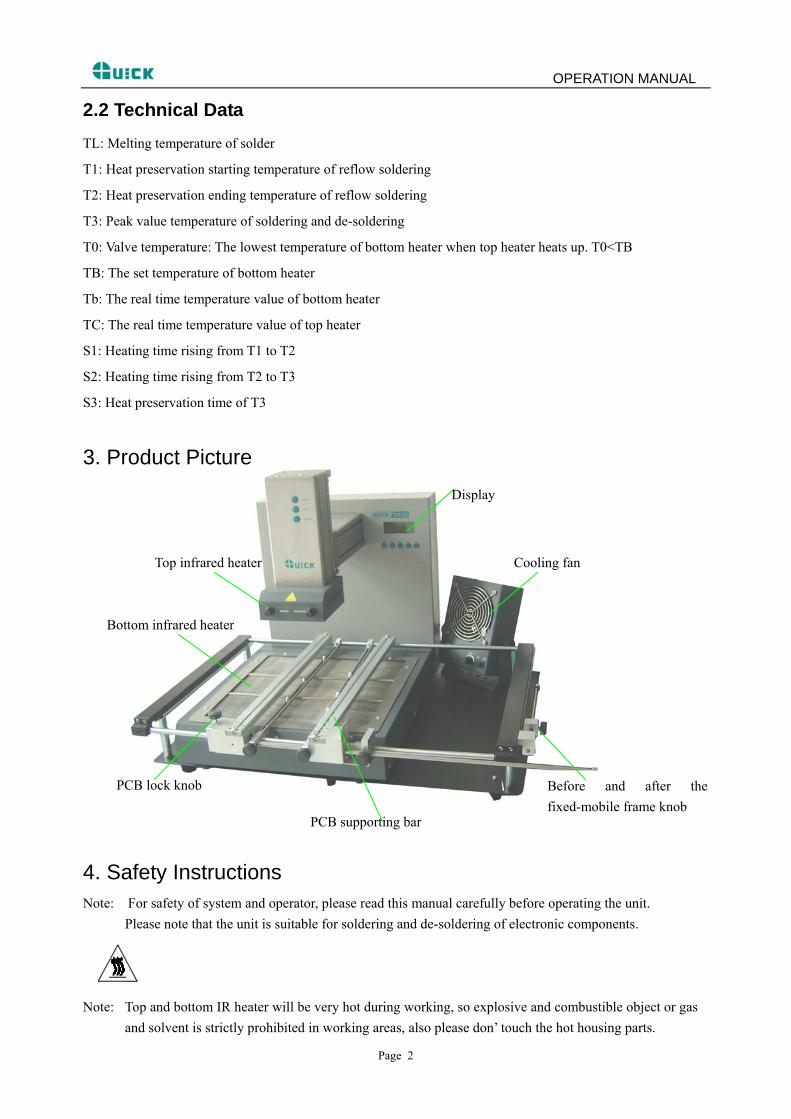
3. Product Picture
Top infrared heater Cooling fan
PCB supporting bar
Before and after the fixed-mobile frame knob
PCB lock knob
Bottom infrared heater
Display
4. Safety Instructions Note: For safety of system and operator, please read this manual carefully before operating the unit. Please note that the unit is suitable for soldering and de-soldering of electronic components.
Note: Top and bottom IR heater will be very hot during working, so explosive and combustible object or gas and solvent is strictly prohibited in working areas, also please don’ touch the hot housing parts.
Page 2
OPERATION MANUAL
Note: The laser alignment device includes a secondary laser device, so don’t see the laser bean directly.
Note: When the system is in trouble and needs maintenance, it should be maintained by an experienced and
authorized technicist or mavin, or contact with service agent or our company. The inside of the unit with dangerous voltage! The inexperienced servcing is dangerous for operators.
5. Install the Unit and Adjust Parts
5.1 Place the Unit Unwrap the packing of the unit, then take it out and put it on the solid level worktable. Put QUICK2035 main
unit on the base plate.
5.2 Check the Unit Please check whether the following parts are in good condition and they aren’t missed. * QUICK2035 Main unit * IR Base plate with PCB Fixture (Optional) * Power cord * Operation Manual * IRsoft Disc * RS232 cable * External cooling fan (Optional) * Monitor (Optional) Note: The parts will be packed according to the packing list, if you don’t purchase the optional part and it
isn’t in the package. If any above part is missed out, please contact with our company or agents immediately.
5.3 Connect the Unit * Please check whether the power voltage accords with the rated voltage on the equipment nameplate. * Please check whether the switches are turned off. (Set to “0”) * Connect Power cord to the power socket behind equipment. * If you use IR Soft, please connect the RS232 connecting cord to the RS232 socket behind the unit. After finishing above steps, insert power plug into power socket, and switch on power.
Page 3
OPERATION MANUAL
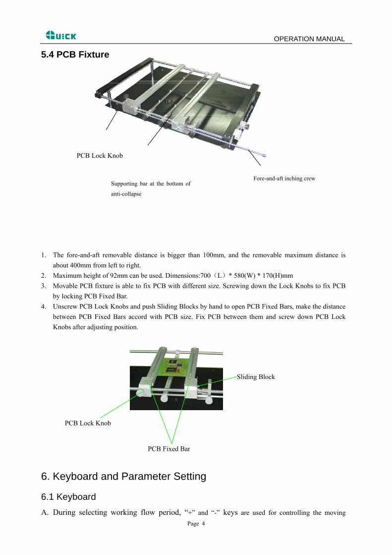
5.4 PCB Fixture
PCB Lock Knob
Fore-and-aft inching crew Supporting bar at the bottom of
anti-collapse
1. The fore-and-aft removable distance is bigger than 100mm, and the removable maximum distance is about 400mm from left to right.
2. Maximum height of 92mm can be used. Dimensions:700(L)* 580(W) * 170(H)mm 3. Movable PCB fixture is able to fix PCB with different size. Screwing down the Lock Knobs to fix PCB
by locking PCB Fixed Bar. 4. Unscrew PCB Lock Knobs and push Sliding Blocks by hand to open PCB Fixed Bars, make the distance
between PCB Fixed Bars accord with PCB size. Fix PCB between them and screw down PCB Lock Knobs after adjusting position.
PCB Lock Knob
Sliding Block
PCB Fixed Bar
6. Keyboard and Parameter Setting
6.1 Keyboard A. During selecting working flow period, “+” and “-” keys are used for controlling the moving
Page 4
OPERATION MANUAL upward or downward of cursor and increase or decrease of number. During the soldering or de-soldering period, also top IR heater haven’t yet started to heat up, key “+” and key “-”are used for controlling movement upward or downward of top IR heater. That is to say, during movement upward and downward of top IR heater, after pressing the key “BEGIN”, “+” and “-” keys make the top heater stop at a proper position.
B. Under the standby condition, if the cooling fan have already drawn back, press “+” and “-” keys to make the top IR heater move up and down.
C. Under the standby condition and the top IR heater is at top position, press “ALIGN” key, the cooling fan (it has laser alignment device inside) will hold out or draw back. When cooling fan completely holds out, the laser alignment device will switch on automatically. After the cooling fan has held out, if you double click “ALIGN” key, the cooling fan will be on or off.
D. Function of “SET” key: Make the BGA-IR enter parameters setting mode and cursor move a step forward.
E. Function of “STOP” key: During the setting mode, make BGA-IR cursor exit until exiting the setting mode; During the soldering or de-soldering period, make BGA-IR exit operation.
F. Function of “START” key: During the standby condition, make BGA-IR get into soldering or de-soldering situation.
G. Function of “Delay” Key: During the soldering or de-soldering process, pressing this key, make the setting value of S3 delays five seconds after the temperature up to T3. If pressing the key continuously, the time of heating (S3) continuously prolongs.
H. “FAN”Key features: an external cooling fan to work or to stop. I. “OK”Function is: when in the settings so that the cursor BGA-IR menu to return to higher levels, until
the return of user interface , and save the changes the result.
6.2 Parameter Setting Parameter settings order as the follows:
A._password: *** (Password settings)
B._select: 0 (Flow settings, it can modify parameter inside.)
C._type: solder (Working mode settings)
D._laser: off (Laser alignment settings)
E._baud: 19200 (Communication speed settings)
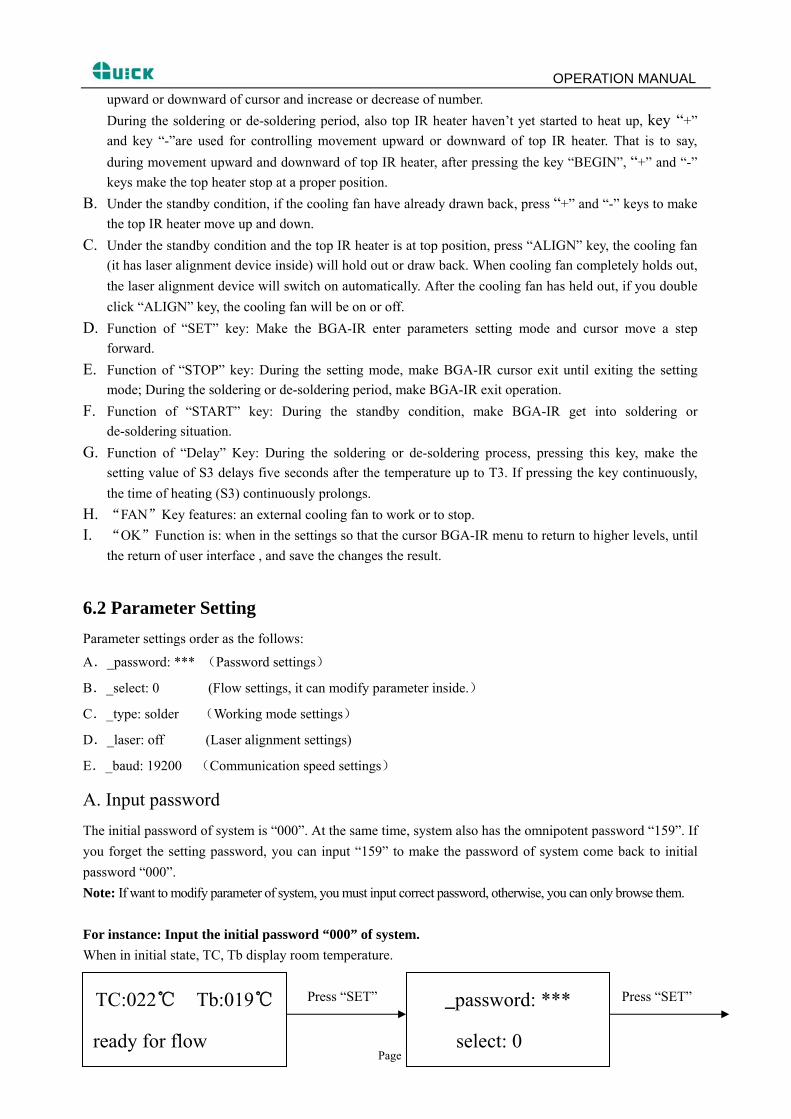
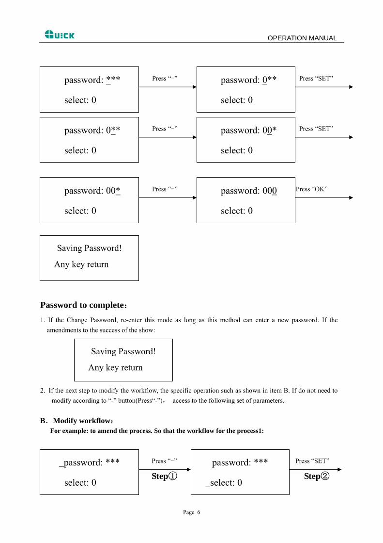
A. Input password The initial password of system is “000”. At the same time, system also has the omnipotent password “159”. If you forget the setting password, you can input “159” to make the password of system come back to initial password “000”. Note: If want to modify parameter of system, you must input correct password, otherwise, you can only browse them. For instance: Input the initial password “000” of system. When in initial state, TC, Tb display room temperature.
Press “SET” Press “SET”
Page 5
TC:022℃ Tb:019℃
ready for flow
_password: ***
select: 0
OPERATION MANUAL
Press “-” Press “SET”
password: ***
select: 0 select: 0
password: 0**
Press “-” Press “SET”
password: 00*
select: 0
password: 0**
select: 0
Press “-” Press “OK”
password: 000
select: 0
password: 00*
select: 0
Any key return
Saving Password!
Password to complete: 1. If the Change Password, re-enter this mode as long as this method can enter a new password. If the
amendments to the success of the show:
Saving Password!
Any key return
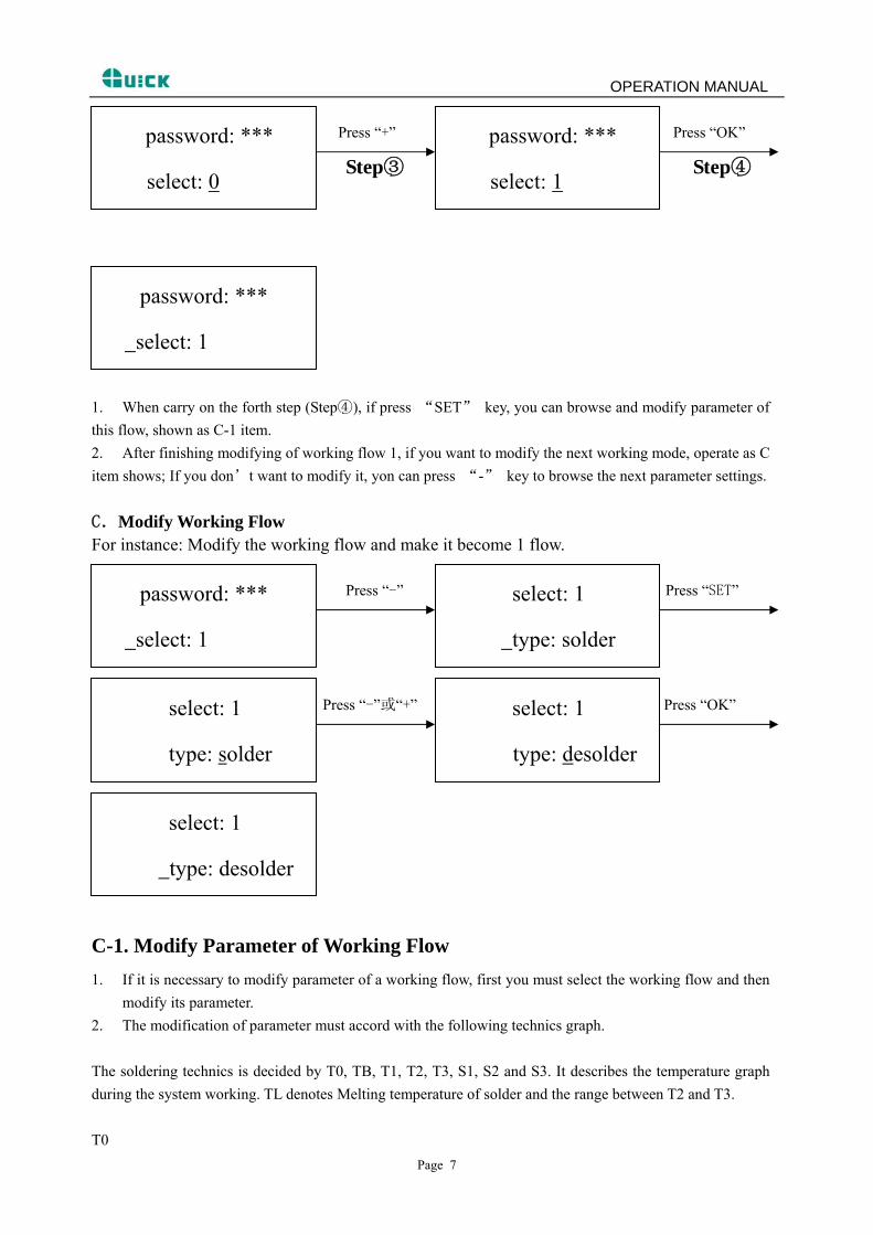
2. If the next step to modify the workflow, the specific operation such as shown in item B. If do not need to modify according to “-” button(Press“-”), access to the following set of parameters.
B.Modify workflow: For example: to amend the process. So that the workflow for the process1:
Press “-” Press “SET”
Step① Step②
password: ***
select: 0
password: ***
select: 0
Page 6
OPERATION MANUAL
Press “+” Press “OK”
Step③ Step④
password: ***
select: 0
password: ***
select: 1
password: ***
select: 1
1. When carry on the forth step (Step④), if press “SET” key, you can browse and modify parameter of this flow, shown as C-1 item. 2. After finishing modifying of working flow 1, if you want to modify the next working mode, operate as C item shows; If you don’t want to modify it, yon can press “-” key to browse the next parameter settings.
C.Modify Working Flow
For instance: Modify the working flow and make it become 1 flow.
Press “-” Press “SET”
password: ***
select: 1 type: solder
select: 1
Press “-”或“+” Press “OK”
select: 1
type: desolder
select: 1
type: solder
select: 1
type: desolder
C-1. Modify Parameter of Working Flow 1. If it is necessary to modify parameter of a working flow, first you must select the working flow and then
modify its parameter. 2. The modification of parameter must accord with the following technics graph. The soldering technics is decided by T0, TB, T1, T2, T3, S1, S2 and S3. It describes the temperature graph during the system working. TL denotes Melting temperature of solder and the range between T2 and T3. T0
Page 7
OPERATION MANUAL
Page 8
T0 is the valve temperature for bottom heater required by top heater when it heats up. Also it is the first temperature of this technics process. When the work flow begins, the bottom heater starts to heat up. After reaching the T0, the top heater begins to heat up. TB, Tb, TC TB: The setting temperature of bottom preheating Tb: Real-time temperature of bottom heating TC: Real-time temperature of top heating T1 It is the heat preservation starting temperature of reflow soldering. It is the second temperature of this technics process. The temperature rises to T1 with a proper speed the component permits. In parameter modifying, use the “↑” and “↓” key to set the value of T1. T2 It is the temperature when finish the heat preservation of reflow soldering. The pre-heating temperature rises to T2, after the time of S1 finishes. Within this time, PCB and component pre-heating is finished and the solder is activated. In parameter modifying, use the “↑” and “↓” key to set the value of T2. T3 It is the peak value temperature of reflow soldering. When the temperature reaches T2, the temperature equably rises to T3 with a definite raising speed. The soldering or de-soldering will be finished when the temperature reaches to the peak value and performs the next step. In parameter modifying, use the “↑” and “↓” key to set the value of T3. TL Melting temperature of solder. At this temperature, the solder starts to melt down and turn into liquid. During the soldering and de-soldering, users can press “CALTL” Key to calibrate the value of TL when the solder turn into liquid. In parameter modifying, use the “↑” and “↓” key to set the value of TL. S1 Heating time rising from T1 to T2. User can set the value in the range of 0~300s. S2 Heating time rising from T2 to T3. User can set the value in the range of 0~300s. S3 Prolonged heating time (Heat preservation time) after the temperature reach T3, and user can also set the value in the range of 0~300s. Unit It’s able to set the unit of display temperature during work flow. In parameter modifying, use “↑” and “↓” keys to set the value of it. Sense It is used for choosing the system’s sensor type. Users can also choose K type sensor used for measuring temperature, besides system’s IR sensor. The signal of chosen sensor will be displayed and used for process
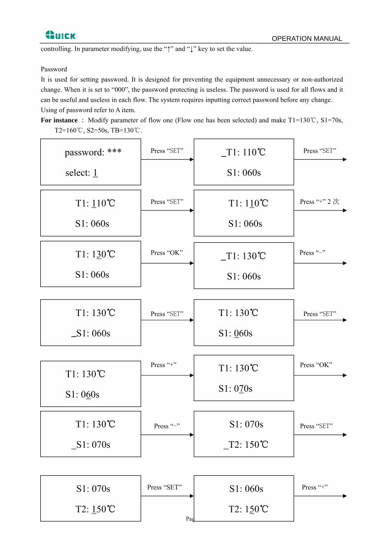
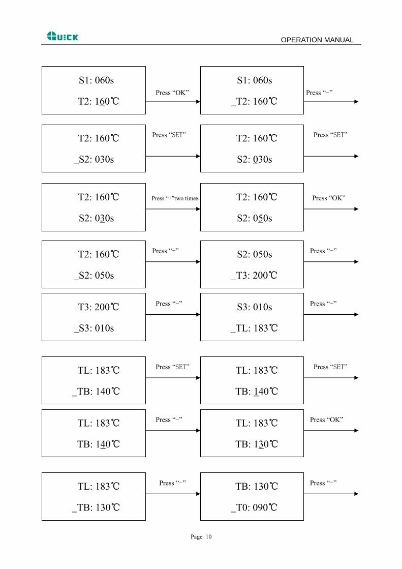
OPERATION MANUAL controlling. In parameter modifying, use the “↑” and “↓” key to set the value. Password It is used for setting password. It is designed for preventing the equipment unnecessary or non-authorized change. When it is set to “000”, the password protecting is useless. The password is used for all flows and it can be useful and useless in each flow. The system requires inputting correct password before any change. Using of password refer to A item. For instance : Modify parameter of flow one (Flow one has been selected) and make T1=130℃, S1=70s,
T2=160℃, S2=50s, TB=130℃.
Press “SET” Press “SET”
S1: 060s
_T1: 110℃
select: 1
password: ***
Press “SET” Press “+” 2 次
T1: 110℃
S1: 060s S1: 060s
T1: 110℃
Press “OK” Press “-”
_T1: 130℃
S1: 060s
T1: 130℃
S1: 060s
Press “SET” Press “SET”
T1: 130℃
S1: 060s
T1: 130℃
_S1: 060s
Press “+” Press “OK”
T1: 130℃
S1: 070s T1: 130℃
S1: 060s
Press “-” Press “SET”
T1: 130℃
S1: 070s
S1: 070s
T2: 150℃
Press “SET” Press “+”
Page 9
S1: 060s
T2: 150℃
S1: 070s
T2: 150℃
OPERATION MANUAL
Press “OK” Press “-”
S1: 060s
T2: 160℃
S1: 060s
T2: 160℃
Press “SET” Press “SET”
T2: 160℃
S2: 030s
T2: 160℃
S2: 030s
Press “+”two times Press “OK”
T2: 160℃
S2: 050s
T2: 160℃
S2: 030s
Press “-” Press “-”
S2: 050s
T3: 200℃
T2: 160℃
S2: 050s
Press “-” Press “-”
S3: 010s
TL: 183℃
T3: 200℃
S3: 010s
Press “SET” Press “SET”
TL: 183℃
TB: 140℃
TL: 183℃
TB: 140℃
Press “-” Press “OK”
TL: 183℃
TB: 130℃
TL: 183℃
TB: 140℃
Press “-” Press “-”
TB: 130℃
T0: 090℃
TL: 183℃
TB: 130℃
Page 10
OPERATION MANUAL
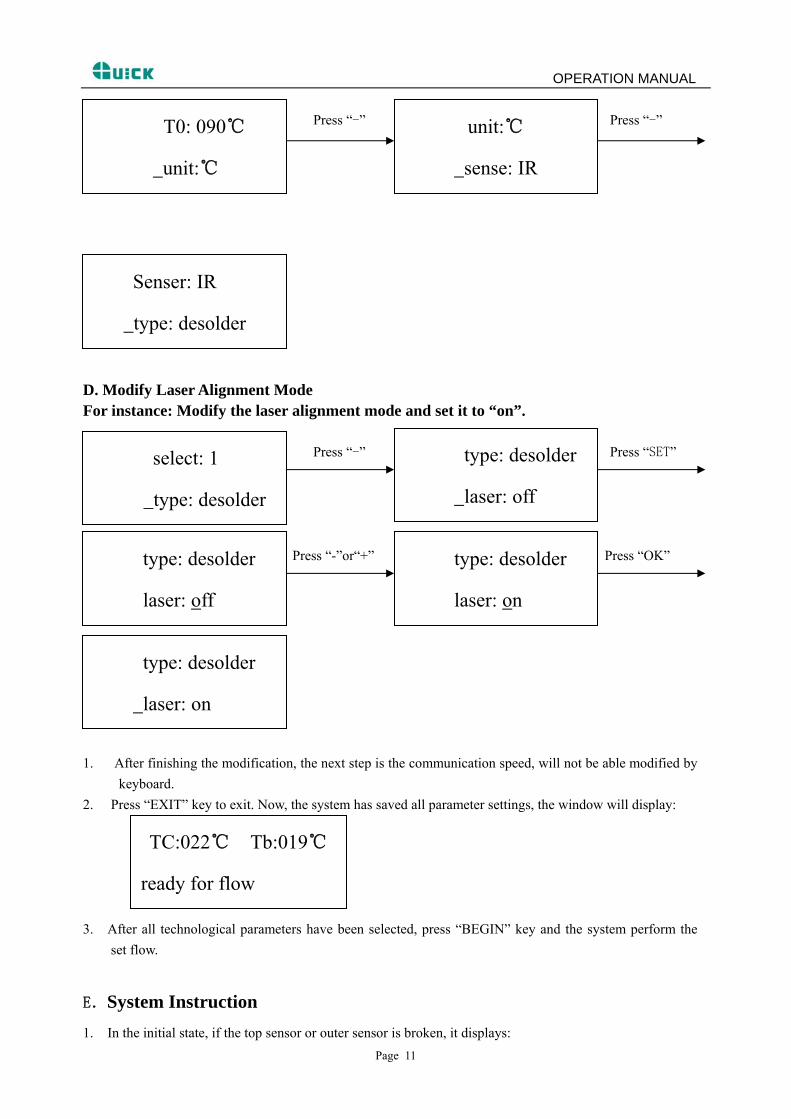
Press “-” Press “-”
unit:℃
sense: IR
T0: 090℃
unit:℃
Senser: IR
type: desolder
D. Modify Laser Alignment Mode For instance: Modify the laser alignment mode and set it to “on”.
Press “-” Press “SET”
type: desolder
laser: off
select: 1
type: desolder
Press “-”or“+” Press “OK”
laser: on
type: desolder type: desolder
laser: off
type: desolder
laser: on
1. After finishing the modification, the next step is the communication speed, will not be able modified by keyboard.
2. Press “EXIT” key to exit. Now, the system has saved all parameter settings, the window will display:
TC:022℃ Tb:019℃
ready for flow
3. After all technological parameters have been selected, press “BEGIN” key and the system perform the set flow.
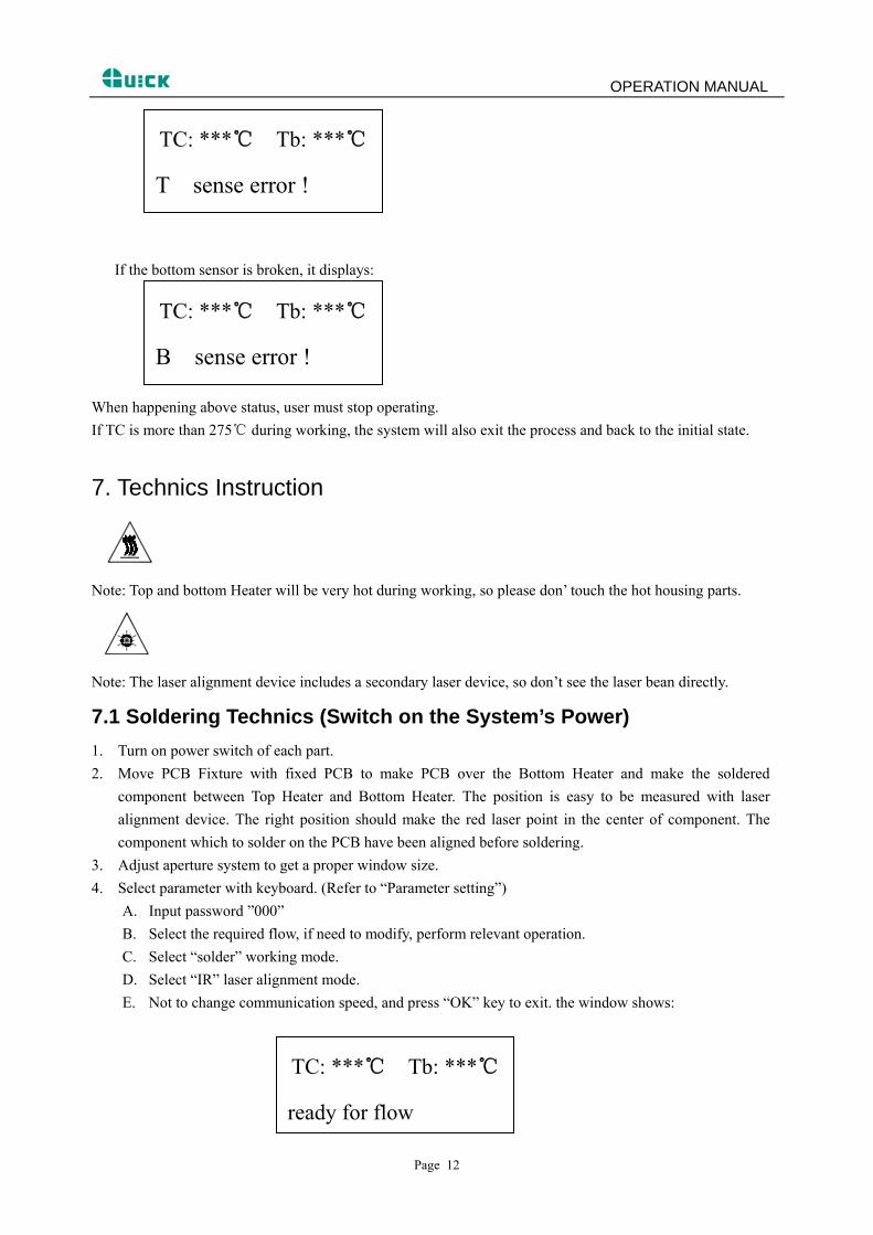
E.System Instruction 1. In the initial state, if the top sensor or outer sensor is broken, it displays:
Page 11
OPERATION MANUAL
TC: ***℃ Tb: ***℃
T sense error !
If the bottom sensor is broken, it displays:
TC: ***℃ Tb: ***℃
B sense error !
When happening above status, user must stop operating. If TC is more than 275 during wor℃ king, the system will also exit the process and back to the initial state.
7. Technics Instruction
Note: Top and bottom Heater will be very hot during working, so please don’ touch the hot housing parts.
Note: The laser alignment device includes a secondary laser device, so don’t see the laser bean directly.
7.1 Soldering Technics (Switch on the System’s Power) 1. Turn on power switch of each part. 2. Move PCB Fixture with fixed PCB to make PCB over the Bottom Heater and make the soldered
component between Top Heater and Bottom Heater. The position is easy to be measured with laser alignment device. The right position should make the red laser point in the center of component. The component which to solder on the PCB have been aligned before soldering.
3. Adjust aperture system to get a proper window size. 4. Select parameter with keyboard. (Refer to “Parameter setting”)
A. Input password ”000” B. Select the required flow, if need to modify, perform relevant operation. C. Select “solder” working mode. D. Select “IR” laser alignment mode. E. Not to change communication speed, and press “OK” key to exit. the window shows:
ready for flow
TC: ***℃ Tb: ***℃
Page 12
OPERATION MANUAL F. Press “BEGIN” key and the system start to work, perform content of selected flow.
5. The window will show series of setting temperatures and the current temperature of Tb and TC during working, and indicate when it reaches T0, T1, T2, T3 and TL. S1, S2 and S3 are counted down and user can know about the setting value clearly.
6. When the temperature reaches TL, there will be a voice signal. 7. When the temperature reaches T3, the voice signal is change to a hurry sound and the system prolongs
heating by S3 seconds, after it, the system will not heat up anymore, and the technical process is over. 8. The system can perform a series of function action during working.
A. After press “BEGIN” key, the top heater move downwards near to bottom. B. After the system sounds unvaryingly, the top heater move upwards and cooling fan spread out to
blow cooling wind. 9. The cooling fan stop working and the whole process has finished.
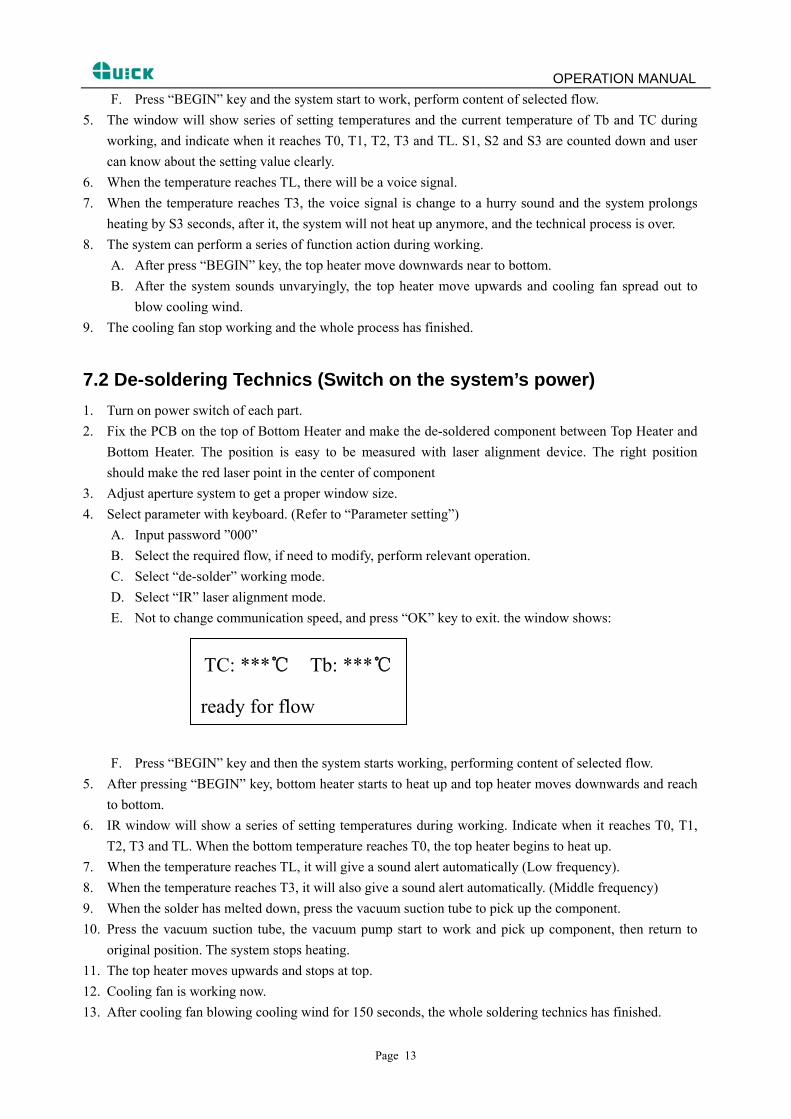
7.2 De-soldering Technics (Switch on the system’s power) 1. Turn on power switch of each part. 2. Fix the PCB on the top of Bottom Heater and make the de-soldered component between Top Heater and
Bottom Heater. The position is easy to be measured with laser alignment device. The right position should make the red laser point in the center of component
3. Adjust aperture system to get a proper window size. 4. Select parameter with keyboard. (Refer to “Parameter setting”)
A. Input password ”000” B. Select the required flow, if need to modify, perform relevant operation. C. Select “de-solder” working mode. D. Select “IR” laser alignment mode. E. Not to change communication speed, and press “OK” key to exit. the window shows:
ready for flow
TC: ***℃ Tb: ***℃
F. Press “BEGIN” key and then the system starts working, performing content of selected flow. 5. After pressing “BEGIN” key, bottom heater starts to heat up and top heater moves downwards and reach
to bottom. 6. IR window will show a series of setting temperatures during working. Indicate when it reaches T0, T1,
T2, T3 and TL. When the bottom temperature reaches T0, the top heater begins to heat up. 7. When the temperature reaches TL, it will give a sound alert automatically (Low frequency). 8. When the temperature reaches T3, it will also give a sound alert automatically. (Middle frequency) 9. When the solder has melted down, press the vacuum suction tube to pick up the component. 10. Press the vacuum suction tube, the vacuum pump start to work and pick up component, then return to
original position. The system stops heating. 11. The top heater moves upwards and stops at top. 12. Cooling fan is working now. 13. After cooling fan blowing cooling wind for 150 seconds, the whole soldering technics has finished.
Page 13
OPERATION MANUAL
8. Turn off the system Please turn off power switch of each part and pull out power plug when not using it.
9. System Maintenance Remark: For ensuring reliable function and maintenance of equipment, please use parts provided by original factory.
Note: After cutting off the power supply, the housing is still very hot, so please don’t use any dangerous or combustible solvent to clean it. Clean parts: Clean the dust on system with clean towel. Use the towel with cleaning oil to clean PCB fixture and orbit. Solder on the gridding of the bottom heater can be cleaned out with hard object.
Page 14