Embed Size (px)
Citation preview

Bulletin No. 2118(2)
QUICK VISION SERIES
VISI
ON
MEA
SURI
NG S
YSTE
MS
CNC VISION MEASURING SYSTEM

2
Continuous Evolution
Production of linear scales Lodine absorption stabilised He-Ne (633 nm) laser for length measurement
Traceability
Design and production of lenses
Optical
Kawasaki plant (Japan)
Software
QVPAK is a software package that is constantly being enhanced.In combination with various other applications, QVPAK delivers multifunctional analysis along with high-speed processing and simple operation.
Knowledge-based Software to Control Quick Vision
With sophisticated edge detection capabilities, an illumination wizard and advanced user-friendly software, the Quick Vision Series satisfies the demand for compactness, high accuracy and vast performance in the field of non-contact dimensional measurement.
Mitutoyo has been selling CNC vision measuring machines - including the Quick Vision Series - since the mid-1980s and is proud of its superb delivery record.Today, measurement professionals expect vision measuring machines to be highly accurate, easy to use, and smaller in size, and Mitutoyo recently relaunched the well-rounded Quick Vision Series to address such demands. The new Quick Vision Series perfectly integrates the advanced optical, sensing, software and vision measuring technologies which Mitutoyo has developed to help customers solve the challenges they face.
Mitutoyo provides traceability across all national standards on a global level. Calibration services are traceable to three main length standards: Laser, End to End and Line types.Also, being the manufacturer of the most comprehensive range of precision measuring instruments available, Mitutoyo offers a number of measuring instruments traceable to national standards such as coordinate measuring machines, optical measuring instruments, form measuring instruments, and vision measuring machines.
The optical system employed in the Quick Vision Series is based on optical technology that Mitutoyo has developed over many years.The optical system design is further enhanced with a flat field objective design and optical lens flare reduction.
Quick Scope
Quick Image
Quick Vision – Perfect Solutions for Any Purpose
Functionality

3
Lineup of Vision Measuring Systems
UMAP Vision System
Hyper Quick Vision WLI
Quick Vision ApexHyper Quick Vision
Quick Vision ACCEL
Quick Scope
Quick Vision – Perfect Solutions for Any Purpose
Accuracy
Quick Vision Active
4
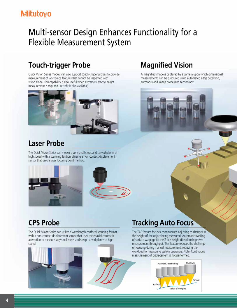
Touch-trigger Probe Magnified Vision
Laser Probe
CPS Probe
Multi-sensor Design Enhances Functionality for a Flexible Measurement System
Quick Vision Series models can also support touch-trigger probes to providemeasurement of workpiece features that cannot be inspected withvision alone. This capability is also useful when extremely precise heightmeasurement is required. (retrofit is also available)
A magnified image is captured by a camera upon which dimensional measurements can be produced using automated edge detection, autofocus and image processing technology.
The Quick Vision Series can measure very small steps and curved planes at high speed with a scanning funtion utilizing a non-contact displacement sensor that uses a laser focusing point method.
The Quick Vision Series can utilize a wavelength confocal scanning format with a non-contact displacement sensor that uses the epaxial chromatic aberration to measure very small steps and steep curved planes at high speed.
Tracking Auto FocusThe TAF feature focuses continuously, adjusting to changes inthe height of the object being measured. Automatic trackingof surface warpage (in the Z-axis height direction) improves measurement throughput. This feature reduces the challenge of focusing during manual measurement, reducing the workload for measuring system operators. Note: Continuous measurement of displacement is not performed.
Parfocal
Parfocal
Surface of workpiece
Automatic Z-axis tracking Objectives

5
QV Index
UMAP Probe
Points From Focus
Image edge detection using a filterMeasurement of a fuel injection nozzle hole’s shape
Measurement of a lens barrel’s shape
Highly accurate height measurement thanks to image auto focus
By using an extremely small stylus with a high aspect ratio made possible by our proprietary sensing technology, the Quick Vision Series can perform contact measurements on small or narrow parts.
White Light Interferometer
WLI optical headImaging optical head
Metal Resin
Using a white light interferometer, the QuickVision Series can perform highly accurate3D measurements in microscopic areas forsurface analysis, small-diameter hole depth,and line and space measurements oncircuit boards.
Contrast information can be used to obtain 3D form data from images at different heights that have been taken by the Quick Vision Series.
Using the QV index to rotatethe workpiece makes itpossible to automaticallymeasure multiple surfaceswithout having to reorientate the workpiece.
6
Main Unit Structure Enables High-accuracy and High-performance 3D Non-contact Measurements
Main Unit Structure Optimized for Highly Accurate Measurements
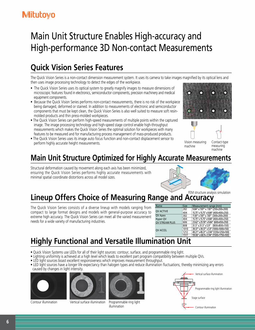
Lineup Offers Choice of Measuring Range and AccuracyName Size Measurement range (mm)
QV ACTIVE202404
9.84" x 7.87" x 7.87" (250×200×200)15.75" x 15.75" x 9.84" (400×400×250)
QV ApexHyper QVQV STREAM PLUS
302 11.81" x 7.87" x 7.87" (300×200×200)404 15.75" x 15.75" x 9.84" (400×400×250)606 23.62" x 25.59" x 9.84" (600×650×250)
QV ACCEL
808 31.5" x 31.5" x 5.9" (800×800×150)1010 39.37" x 39.37" x 5.9" (1000×1000×150)1212 49.21" x 49.21" x 3.94" (1250×1250×100)1517 59.06" x 68.9 x 3.94" (1500×1750×100)
Highly Functional and Versatile Illumination Unit
The Quick Vision Series is a non-contact dimension measurement system. It uses its camera to take images magnified by its optical lens and then uses image processing technology to detect the edges of the workpiece.
Structural deformation caused by movement along each axis has been minimized,ensuring the Quick Vision Series performs highly accurate measurements with minimal spatial coordinate distortions across all model sizes.
The Quick Vision Series consists of a diverse lineup with models ranging from compact to large format designs and models with general-purpose accuracy to extreme high accuracy. The Quick Vision Series can meet all the varied measurement needs for a wide variety of manufacturing industries.
• Quick Vision Systems use LEDs for all of their light sources: contour, surface, and programmable ring light.• Lighting uniformity is achieved at a high level which leads to excellent part program compatibility between multiple QVs.• LED light sources boast excellent responsiveness which improves measurement throughput.• LED light sources have a longer life expectancy than halogen types and reduce illumination fluctuations, thereby minimizing any errors caused by changes in light intensity.
• The Quick Vision Series uses its optical system to greatly magnify images to measure dimensions of microscopic features found in electronics, semiconductor components, precision machinery and medical equipment components.
• Because the Quick Vision Series performs non-contact measurements, there is no risk of the workpiece being damaged, deformed or stained. In addition to measurements of electronic and semiconductor components that must be kept clean, the Quick Vision Series is also well suited to measure soft resin-molded products and thin press-molded workpieces.
• The Quick Vision Series can perform high-speed measurements of multiple points within the captured image. The image processing technology and high-speed stage control enable high-throughput measurements which makes the Quick Vision Series the optimal solution for workpieces with many features to be measured and for manufacturing process management of mass-produced products.
• The Quick Vision Series uses its image auto focus function and non-contact displacement sensor to perform highly accurate height measurements.
FEM structure analysis simulation
Vertical surface illumination
Programmable ring light illumination
Contour illumination
Stage surface
Contour illumination Vertical surface illumination Programmable ring light illumination
Vision measuring machine
Contact-type measuring machine
Quick Vision Series Features

7
Highly Functional Lighting for Exceptional Edge Detection and Automatic Measurements
Programmable Ring Light (PRL)Changing the positions of the two curved mirrors sets the ring light's obliquity to any chosen value between 30° and 80°.This is effective for enhancing the edges of inclined surfaces or very small steps. Furthermore, the PRL light's illumination can be controlled independently in every direction (front and back, right and left). This makes it possible to configure highly variable lighting settings to match measurement locations.
Objective lens PRL illumination
Measuring the top and bottom widths of metallisation patterns on an IC package
Four-quadrant LED light
Parabolic mirror
Toroidal mirror
Workpiece top face
Objective lens
Uniform illumination can be obtained from the four-quadrant LEDs, whose brightness is independently controllable.
Obliquity can be set by controlling the positions of the two types of mirrors that move independently of the Z-Axis.
Front
Back
RightLeft
Front
Back
RightLeft
Front
Back
RightLeft
Front
Back
RightLeft
Tracking Auto Focus (TAF)The TAF feature focuses continuously, adjusting to changes in the height of the object being measured. Automatic tracking of surface variation and warpage (in the Z-axis height direction) improves measurement throughput. The feature also removes the need of focusing during manual measurement, reducing the work burden for measuring system operators.Note: Continuous measurement of displacement is not performed.
Parfocal
Parfocal
Surface of workpiece
Automatic Z-axis tracking Objectives
Laser source Semiconductor laser (peak wavelength: 690nm)
Laser safety Class 2 (J IS C6802:2011, EN/ IEC 60825-1:2007)
Autofocus system Objective coaxial autofocusing (knife-edge method)
Applicable objectives QV-HR1X QV-SL1X QV-HR2.5X QV-SL2.5X QV-HR5X
Tracking range * 0.25" (6.3 mm)(±0.12"/3.15mm)
0.25" (6.3 mm)(±0.12"/3.15mm)
0.04" (1 mm)(±0.02"/0.5mm)
0.04" (1 mm)(±0.02"/0.5mm)
0.01" (0.25mm)(±0.005"0.125mm)
* When using Tracking Auto Focus, be sure to set upper and lower limits in the software to prevent collisions between the objective and the workpiece. The tracking range depends on the surface texture and reflectance of a workpiece.

8
Programmable Power Turret
PPT1XField of view: 2.49 × 1.86 mm
PPT2XField of view: 1.24 × 0.93 mm
PPT6XField of view: 0.41 × 0.31 mm
QV-HR2.5X
PPT1XField of view: 6.27 × 4.70 mm
PPT2XField of view: 3.13 × 2.35 mm
PPT6XField of view: 1.04 × 0.78 mm
QV-HR1X
PPT1XField of view: 1.24 × 0.93 mm
PPT2XField of view: 0.62 × 0.47 mm
QV-HR5X
PPT6XField of view: 0.20 × 0.15 mm
QV-HR10X
PPT1XField of view: 0.62 × 0.47 mm
PPT2XField of view: 0.31 × 0.23 mm
PPT6XField of view: 0.10 × 0.07 mm
Color Camera Specifications That Improve the Observation Function (PRO3 Model)To improve the observations, Mitutoyo offers the PRO3 model equipped with a high-resolution color CCD camera. The CCD camera enables the PRO3 to perform highly accurate measurements without a decrease in the resolution of the screen.
Printed Circuit Board QFP Package Leads IC Package LCD Color Filter Resin-molded Products
Objective Lenses
Various objective lenses for the QVs
PRO modelprogrammablepower turret
Monitor magnification*1,*3 15X 29X 58X 72X 87X 144X 173X 290X 430X 580X 720X 870X 1440X 1730X 4300XField of view (mm) 12.54×9.4 6.27×4.7 3.13×2.35 2.49×1.86 2.09×1.56 1.24×0.93 1.04×0.78 0.62×0.47 0.41×0.31 0.31×0.23 0.25×0.18 0.20×0.15 0.12×0.09 0.10×0.07 0.04×0.030.5X objective lens1X objective lens2.5X objective lens5X objective lens10X objective lens*2
25X objective lens*2
*1: With QVPAK version 13 or later, the size of the video window can be changed. Monitor magnification shown in the above table is a reference value at the same display magnification when using 56 cm / 22-inch wide LCD monitor.
*2: When the 10X objective lens or 25X objective lens is used in combination with the 2X or 6X magnification of the power turret, the brightness may be insufficient depending on the workpiece.
*3: For the PRO3 models, the monitor magnifications are 1.34 times and the field of view are approximately 0.75 times those of the PRO model.
The QV's programmable power turret has excellent magnification repeatability which makes it suitable for highly accurate measurements.Furthermore, the rich lineup of objectives contains lenses with magnifications ranging from 0.5X to 25X, making it possible to select the optimal optical system to match the measurement target feature.It is easy to install new objective lenses any time by using the optional calibration chart and compensation chart. Additional objectives can be purchased at a later date.
Powerful Vision Optics Incorporate Mitutoyo’s High Performance Lenses For Greater Optical Flexibility
9
Resin-molded product IC package Chamfered part of a machined surface
Multi-function Control BoxThis multi-function control box was developed for maximum ease of use.
Emergency-stop button
Four-digit status LED
Variable speed control
Accuracy Conforms to ISO10360-7 The accuracy specifications of some models in the Quick Vision Apex Series confrom to ISO10360-7. Contact Mitutoyo for details on applicable models.
Guaranteed Accuracies• Length measurement error EU,MPE
• Probing error PF2D,MPE
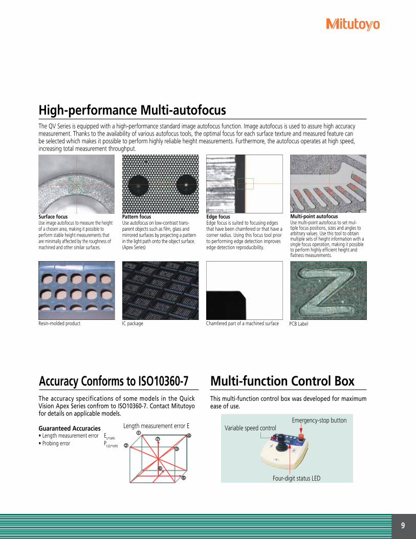
High-performance Multi-autofocus
Surface focusUse image autofocus to measure the height of a chosen area, making it possible to perform stable height measurements that are minimally affected by the roughness of machined and other similar surfaces.
Pattern focusUse autofocus on low-contrast trans-parent objects such as film, glass and mirrored surfaces by projecting a pattern in the light path onto the object surface. (Apex Series)
Edge focusEdge focus is suited to focusing edges that have been chamfered or that have a corner radius. Using this focus tool prior to performing edge detection improves edge detection reproducibility.
Multi-point autofocusUse multi-point autofocus to set mul-tiple focus positions, sizes and angles to arbitrary values. Use this tool to obtain multiple sets of height information with a single focus operation, making it possible to perform highly efficient height and flatness measurements.
Length measurement error E
The QV Series is equipped with a high-performance standard image autofocus function. Image autofocus is used to assure high accuracy measurement. Thanks to the availability of various autofocus tools, the optimal focus for each surface texture and measured feature can be selected which makes it possible to perform highly reliable height measurements. Furthermore, the autofocus operates at high speed, increasing total measurement throughput.
PCB Label

10
Compact CNC Vision Measuring SystemQV Active
QV Active
Specifications
• The edge detection capability and functions of the measurement software QVPAK are as powerful as those of the higher model QV Apex. This enables the QV Active to surpass the conventional image of a compact model.
• Each lighting unit employs long-life white LEDs with low power consumption. The LED light sources boast excellent responsiveness which improves measurement throughput.
• QV Active is equipped with a high resolution CMOS camera system that achieves high accuracy and high-resolution color images.
• While the QV Active is a compact model, it has a more-than-adequate Z-axis stroke of 200 mm.
• A Mitutoyo developed zoom optical system with interchangeable objectives offers maximum workpiece measurement flexibility.
QV Active 202 QV Active 404
Model QV-L202Z1L-D QVT1-L202Z1L-D QV-L404Z1L-D QVT1-L404Z1L-D
Measuring range (X×Y×Z) 9.84“ x 7.87“ x 5.91“ (250 x 200 x 150 mm)(250×200×118: when a 1X objective lens is used)
15.75“ x 15.75“ x 7.87“(400 x 400 x 200 mm)(400×400×168: when a 1X objective lens is used)
Touch probe equipped No Yes No YesResolution 0.1µmScale type Linear encoderObservation unit type Zoom (8 positions)Image sensor Color CMOS camera
Illumination UnitCo-axial Light White LEDTransmitted Light White LEDPRL 4-quadrant fixed white LED
Accuracy*1
E1X, E1Y (2+3L/1000) µmE1Z (3+5L/1000) µmE2 (2.5+4L/1000) µmAccuracy guaranteed with optics specified Objective lens 1.5X and 3.5X Zoom ratio
Touch-probe measuring accuracy*1 E1X, E1Y, E1Z — (2.4+3L/1000) µm — (2.4+3L/1000) µmAccuracy guaranteed temperature range 20±1°C 18 - 23°C 20±1°C 18 - 23°CSize of stage glass 12.24" x 10.59" (311×269mm) 18.35" x 18.9" (466×480mm)Maximum stage loading*2 22 lbs. (10 kg) 44 lbs. (20 kg)Dimensions (WxDxH) 22.44" x 30.2" x 33.27" (570×767×845mm) 30.55" x 51.3" x 39.53" (776×1303×1004mm)Mass (including machine stand) 342 lbs. (155kg) 714 lbs. (324kg)Temperature compensation function — Manual — Manual
*1 Inspected to a Mitutoyo standard. L = measured length (mm)*2 Does not apply for unbalanced or concentrated loads.

11
Standard CNC Vision Measuring SystemQV Apex
QV ApexQV Apex 302PRO
Specifications
*1 The specific combination of 1X, 2X and 4X or 1X, 2X, 4X and 6X is available by custom order.*2 The color LED lighting or halogen lighting specification is available by custom order.*3 Determined by Mitutoyo's inspection method. L is the measured length (mm). The optical condition for accuracy assurance is to be (QV-HR2.5X or QV-SL2.5X) + Middle magnification of the tube lens.*4 An excessively biased or concentrated load is excluded.* The Laser Auto Focus (LAF) specification is available by custom order.
• QV Series standard models range in size from compact to large.• A model equipped with the tracking focus function that allows
continuous focusing in response to change in workpiece height is also available. This results in improved measurement throughput.
• The lineup, including the PRO3 models equipped with a color CCD camera, satisfies a wide range of demands (optional).
• The QV Apex 404 and QV Apex 606 X-axis and Y-axis drive speeds reach 400 mm/second. This greatly contributes to throughput improvement particularly for workpieces that involve a large range of travel.
• The accuracy of this model (Apex type only) conforms to ISO10360-7:2011 (specifications on request)
Model QV Apex 302 QV Apex 404 QV Apex 606Optical system PRO PRO3 PRO PRO3 PRO PRO3Tracking Auto Focus device — ● — ● — ● — ● — ● — ●
Measuring range X-axis 11.81” / 300mm 15.75” / 400mm 23.62” / 600mmY-axis 7.87” / 200mm 15.75” / 400mm 25.59” / 650mmZ-axis 7.87” / 200mm 9.84” / 250mm 9.84” / 250mm
Resolution of scale / Scale type 0.1µm/Linear EncoderObservation Unit*1 PPT1X-2X-6XImaging Device B&W CCD 3CCD Color B&W CCD 3CCD Color B&W CCD 3CCD Color
Illumination Unit*2
Co-axial light White LEDTransmitted Light White LEDPRL White LED
Accuracy*3
E1X, E1Y (1.5+3L/1000)µmE1Z (1.5+4L/1000)µmE2XY (2+4L/1000)µm
Operating Temperature range
Ambient temperature 20±1˚CTemperature variation 2˚C / 8H
Stage glass size 15.71” x 10.67”(399 x 271mm)
19.41” x 21.69”(493 x 551mm)
27.44” x 29.84”(697 x 758mm)
Maximum stage loading*4 44 lbs. (20kg) 88 lbs. (40kg) 110 lbs. (50kg)
Main unit external dimensions 37.44” x 33.82” x 41.06”( 951 x 859 x 1043mm)
55.39” x 40.43” x 54.37”( 1407 x 1027 x 1381mm)
78.15” x 51.54” x 61.81”( 1985 x 1309 x 1570mm)
Main unit mass (including the sub-base) 794 lbs. (360kg) 1276 lbs. (579kg) 3197 lbs. (1450kg)

12
High-accuracy CNC Vision Measuring SystemHyper QV
Hyper QV
Specifications
*1 The specific combination of 1X, 2X and 4X or 1X, 2X, 4X and 6X is available by custom order.*2 The color LED lighting or halogen lighting specification is available by custom order.*3 Determined by Mitutoyo's inspection method. L is the measured length (mm). The optical condition for accuracy assurance is to be (QV-HR2.5X or QV-SL2.5X) + Middle magnification of the tube lens.*4 An excessively biased or concentrated load is excluded.* The Laser Auto Focus (LAF) specification is available by custom order.
Hyper QV 404PRO
• The Hyper QV is a highly accurate model equipped with a high-resolution/accuracy scale.
• A lineup similar to the QV Apex containing models that range in size from compact to large means a model ideally suited for the size of the workpiece can be selected.
• The model equipped with the tracking focus function allowing continuous focusing in response to change in workpiece height is also available. This results in improved measurement throughput.
• This model is standard-equipped with an automatic temperature compensation function that uses a temperature sensor on the main unit of the measuring machine and a temperature sensor for the workpiece, thus guaranteeing the stated accuracy specification applies over the temperature range 18 to 23°C for stable measurement results.
• The accuracy of this model conforms to ISO10360-7:2011 (specifications on request).
Model Hyper QV 302 Hyper QV 404 Hyper QV 606Optical system PROTracking Auto Focus device — ● — ● — ●
Measuring range (X×Y×Z) 11.81”×7.87”×7.87” (300×200×200mm) 15.75”×15.75”×9.84” (400×400×250mm) 23.62”×25.59”×9.84” (600×650×250mm)Resolution of scale / Scale type 0.02µm/linear encoderObservation unit*1 PPT1X-2X-6XImaging device B&W CCD
Illumination unit*2
Co-axial light White LEDTransmitted light White LEDPRL White LED
Accuracy*3
E1X, E1Y (0.8+2L/1000)µmE1Z (1.5+2L/1000)µmE2XY (1.4+3L/1000)µm
Operating temperature range
Ambient temperature 18 ~ 23˚CTemperature variation 0.5˚C / 1H and 1˚C / 24H
Stage glass size 15.71” × 10.67” (399×271mm) 19.41” × 21.69” (493×551mm) 27.44” × 29.84” (697× 58mm)Maximum stage loading*4 44 lbs. (20kg) 88 lbs. (40kg) 110 lbs. (50kg)
Main unit external dimensions 37.44” × 33.82” × 41.06”(951×859×1043mm)
55.39” × 40.43” × 54.37”(1407×1027× 381mm)
78.15” × 51.54” × 61.81”(1985×1309× 570mm)
Main unit mass (including the sub-base) 794 lbs. (360kg) 1276 lbs. (579kg) 3197 lbs. (1450kg)Temperature compensation function automatic

13
Non-stop CNC Vision Measuring SystemQV STREAM PLUS
QV STREAM PLUS
Displacement Displacement DisplacementImaging
Camera Continuous displacement Camera
Imaging Imaging Completion of imaging Batchmeasurement
Specifications
*1 The specific combination of 1X, 2X and 4X or 1X, 2X, 4X and 6X is available by custom order.*2 Only one of the illumination functions (reflected, transmitted, and PRL illumination) can be set in STREAM mode. The 4-way PRL illumination can be set to the entire lighting (4-direction lighting) or single-direction lighting.*3 Enable to use cyan only while using STREAM mode.*4 Determined by Mitutoyo’s inspection method. L is the measured length (mm). The optical condition for accuracy assurance is to be (QV-HR2.5X or QV-SL2.5X) + Middle magnification of the tube lens.*5 An excessively biased or concentrated load is excluded* The Laser Auto Focus (LAF) specification is available by custom order.
• The QV STREAM PLUS is an innovative vision measuring machine that acquires images without stopping the stage. This is accomplished by synchronizing the main unit's X-axis and Y-axis traversal with strobe illumination.
Conventional vision measuring machines repeat the displacement, stop, measurement and displacement cycle which restricts throughput.
In contrast, the QV STREAM PLUS realizes non-stop vision measurement (stream mode) by eliminating acceleration, deceleration and stop times. Consequently, this dramatically reduces the overall measurement time.
• The model equipped with the tracking focus function that allows continuous focusing in response to change in workpiece height is also available. This results in improved measurement throughput.
• The lineup is similar to the QV Apex range. The models range in size from compact to large. Hence, there is always one that ideally suits the workpiece to be measured.
Model QV STREAM PLUS 302 QV STREAM PLUS 404 QV STREAM PLUS 606Optical system PROTracking Auto Focus device — ● — ● — ●
Measuring range (X×Y×Z) 11.81 × 7.87” × 7.87”(300×200×200mm) 15.75” × 15.75” × 9.84”(400×400×250mm) 23.62” × 25.59” × 9.84”(600×650×250mm)Resolution of scale / Scale type 0.1µm/linear encoderObservation unit*1 PPT1X-2X-6XImaging device B&W CCD
Illumination unit*2
Co-axial light*3 Color LEDTransmitted light Blue LEDPRL*3 Color LED
Accuracy*4
E1X, E1Y (1.5+3L/1000)µmE1Z (1.5+4L/1000)µmE2XY (2+4L/1000)µm
Operating temperature range
Ambient temperature 20±1˚CTemperature variation 2˚C / 8H
Stage glass size 15.71”× 10.67”(399×271mm) 19.41”× 21.69”(493 x 551mm) 27.44”× 29.84”(697×758mm)Maximum stage loading *5 44 lbs. (20kg) 88 lbs. (40kg) 110 lbs. (50kg)
Main unit external dimensions 37.44”× 33.82”×41.06”(951×859×1043mm)
55.39”×40.43”×54.37”(1407×1027×1381mm)
78.15”×51.54”× 61.81”(1985×1309×1570mm)
Main unit mass (including the sub-base) 794 lbs. (360kg) 1276 lbs. (579kg) 3197 lbs. (1450kg)
QV STREAM PLUS 606PRO

14
Large CNC Vision Measuring SystemQV ACCEL
• By using highly functional edge detection and image auto focus, the QV ACCEL can perform highly accurate height measurements.
The QV ACCEL is standard-equipped with a pattern focus function that can be used to perform image auto focusing even on transparent objects such as film and glass.
• The model equipped with the tracking focus function that allows continuous focusing in response to change in workpiece height delivers improved measurement throughput and is also available.
QV ACCEL• The QV ACCEL is a moving-bridge type vision measuring machine.
Because the stage remains stationary, the fixtures used to hold workpieces in place can be simplified, leading to a reduction in the amount of work required to create these fixtures. In addition, the QV ACCEL is suited to measurements of workpieces with short life cycles as well as thin and light-weight workpieces.
• The QV ACCEL is optimal for measurements of printed circuit boards whose density and resolution continue to increase, as well as metal masks and screen plates. The QV ACCEL is also optimal for measurements on glass circuit boards, film and other components of display panels.
Model QV ACCEL 808 QV ACCEL 1010 QV ACCEL 1212Optical system PRO PRO3 PRO PRO3 PRO PRO3Measuring range (X×Y×Z) 31.5” × 31.5”× 5.90” (800×800×150mm) 39.37” × 39.37” × 5.90”(1000×1000×150mm) 49.21” × 49.21”× 3.94” (1250×1250×100mm)Resolution of scale / Scale type 0.1µm/linear encoderObservation unit*1 PPT1X-2X-6XImaging device B&W CCD Color CCD B&W CCD Color CCD B&W CCD Color CCD
Illumination unit*2
Co-axial light White LEDTransmitted light White LEDPRL White LED
Accuracy*3
E1X, E1Y (1.5+3L/1000)µm (2.2+3L/1000)µmE1Z (1.5+4L/1000)µm (2.5+5L/1000)µmE2XY (2.5+4L/1000)µm (3.5+4L/1000)µm
Repeatability*3 Short dimension XYaxis
3σ=0.2µmLong dimension 3σ=0.7µm 3σ=1.5µm
Operating temperature range
Ambient temperature 20±1˚CTemperature variation 2˚C / 8H
Stage glass size 34.76” × 37.72”(883×958mm) 46.69” × 46.69”(1186 × 1186mm) 56.69” × 56.69”(1440×1440mm)Maximum stage loading*4 22 lbs. (10kg) 66 lbs. (30kg) 66 lbs. (30kg)
Main unit external dimensions 58.07" x 73.23" x 62.13" (1475×1860×1578mm)
75.28" x 84.29" x 63.11" (1912×2141×1603mm)
85.28" x 93.31" x 61(2166×2370×1554mm)
Main unit mass 5666 lbs. (2570kg) 6504 lbs. (2950kg) 7937 lbs. (3600kg)
Specifications
*1 The specific combination of 1X, 2X and 4X or 1X, 2X, 4X and 6X is available by custom order.*2 The color LED lighting or halogen lighting specification is available by custom order.*3 Determined by Mitutoyo's inspection method. L is the measured length (mm). The optical condition for accuracy assurance is to be (QV-HR2.5X or QV-SL2.5X) + Low magnification of the tube lens.*4 An excessively biased or concentrated load is excluded.* The Laser Auto Focus (LAF) specification is available by custom order.
QV ACCEL 1212PRO
QV ACCEL 808PRO

15
Ultra-high Accuracy CNC Vision Measuring SystemULTRA QV 404
ULTRA QV 404ULTRA QV 404PRO
• The ULTRA QV 404 is an ultra-precise CNC vision measuring machine that realizes a measurement accuracy of E1XY: (0.25 + L/1000)µm.
• To improve the maneuverability of each axis, Mitutoyo uses aerostatic bearings developed in our highly accurate 3D measuring machines as the guidance systems for the X-, Y- and Z-axes.
• This model is standard-equipped with an automatic temperature compensation function that uses a temperature sensor on the main unit of the measuring machine and a temperature sensor
SpecificationsModel ULTRA QV 404Optical system PROTracking Auto Focus device — ●
Measuring range (X×Y×Z) 15.75” x 15.75” x 7.87” (400×400×200mm)Resolution of scale / Scale type 0.01µm / linear encoderObservation unit*1 PPT1X-2X-6XImaging device B&W CCD
Illumination unitCo-axial light HalogenTransmitted light HalogenPRL Halogen
Accuracy*2
E1X, E1Y (0.25+L/1000)µmE1Z (50mm stroke)*3 (1+2L/1000)µmE1Z (Full stroke) (1.5+2L/1000)µmE2XY (0.5+2L/1000)µm
On-screen repeatability 3σ=0.2µmAuto focus repeatability σ=0.4µmOperating temperature range
Ambient temperature 19 ~ 23˚CTemperature variation 0.5˚C / 1H and 1˚C / 24H
Stage glass size 19.41” x 21.69” (493x551mm)Maximum stage loading*4 88 lbs. (40kg)Main unit external dimensions 46.14” x 68.31” x 75.2” (1172×1735×1910mm) Main unit mass (including the sub-base) 4740 lbs. (2150kg)Operating air pressure 0.4 MPa*5
Required air flow rate 300L/min(ANR)*6
Temperature compensation function automatic
*1 The specific combination of 1X, 2X and 4X or 1X, 2X, 4X and 6X is available by custom order.
*2 Determined by Mitutoyo's inspection method. L is the measured length (mm). The optical condition for accuracy assurance is to be QV-5X + Middle magnification of the tube lens.
for the workpiece, guaranteeing the stated accuracy specification applies over the temperature range of 19 to 23°C for stable measurement results.
• The model equipped with the tracking focus function allowing continuous focusing in response to change in workpiece height is also available. This results in improved measurement throughput.
• The accuracy of this model conforms to ISO10360-7:2011 (specifications on request).
NOTE: A start-up system (relocation detection sensor) is an integral security feature of machines of this series and will disable their operation if subject to relocation or strong vibration. Please be advised to contact your nearest Mitutoyo Service Centre as soon as possible or in advance of such circumstance.
*3 Verified at shipment from factory.*4 An excessively biased or concentrated load is excluded.*5 Air supply pressure to be in range 0.5 - 0.9MPa.*6 Indicates the flow rate under normal conditions. * The Laser Auto Focus (LAF) specification is available by custom order.

16
QV TP Series CNC Vision Measuring System Equipped with a Touch/Trigger Probe
QV Touch-Trigger Probe• The QV TP Series enables non-contact measurements and contact measurements on the same machine. This is achieved using a camera for
non-contact measurements and a touch-trigger probe for contact measurements.• The QV TP Series supports measurements of 3D workpieces such as press-molded products, resin-molded products and machined products
that could not be measured with conventional image processing alone.• The QV TP Series is equipped with a probe module change rack making it possible to switch between vision measurement and touch
trigger probe measurement during a sequence of automatic measurements. Furthermore, storing the characteristics of different styli makes it possible to perform measurements on multiple surfaces.
• The accuracy of these models (excluding QV ACCEL type) conforms to ISO10360-7:2011 (specifications on request).
SpecificationsQV TP ACTIVEModel QV TP 202 QV TP 404Optical system Active ActiveMeasuring range by vision probe*1 (X×Y×Z) 9.84" x 7.87" x 5.9" (250×200×200 mm) 15.75"x 15.75"x 7.78" (400x400x200 mm)Measuring range by touch probe*1 (X×Y×Z) 7.24" x 7.87" x 7.87" (184×200×150 mm) 15.75"x 15.75"x 6.61" (400x400x168 mm)Resolution of scale / Scale type 0.1µm / linear encoder 0.1µm / linear encoderObservation unit*2 Zoom (8 positions) Zoom (8 positions)Imaging device Color (CMOS) camera Color (CMOS) camera
Illumination unitCo-axial light White LED White LEDTransmitted light White LED White LEDPRL 4-quadrant fixed white LED 4-quadrant fixed white LED
Measuring accuracy*3
(Vision)E1X, E1Y (2+3L/1000)µm (2+3L/1000)µmE1Z (3+5L/1000)µm (3+5L/1000)µm
TP measuring accuracy*3 E1X, E1Y, E1Z (2.4+4L/1000)µm (2.4+4L/1000)µm
Operating temperature range Ambient temperature 18 ~ 23˚C 18 ~ 23˚CTemperature variation 0.5˚C / 1H and 1˚C / 24H 0.5˚C / 1H and 1˚C / 24H
Stage glass size 12.28" x 10.59" (311×269 mm) 18.34" x 18.89" (466x480 mm)Maximum stage loading *4 22 lbs. (10kg) 44.09 lbs. (20 kg)Main unit external dimensions (570x767x845 mm) 30.55" x 51.29" x 39.52" (776x1303x1004 mm)Main unit mass (including the sub-base) 341.72 lbs. (155kg) 714.30 lbs. (324kg)Temperature compensation function manual manual*1 Measuring range is smaller than the dimension in the specifications table above when the machine is equipped with module change rack, master ball and calibration ring.*2 The specific combination of 1X, 2X and 4X or 1X, 2X, 4X and 6X is available by custom order.*3 Determined by Mitutoyo's inspection method. L is the measured length (mm). The optical condition for accuracy assurance is to be (QV-HR2.5X or QV-SL2.5X) + Middle magnification of the tube lens.*4 An excessively biased or concentrated load is excluded.* The Laser Auto Focus (LAF) specification is available by custom order.
QV TP Apex 302PRO

17
SpecificationsQV TP ApexModel QV TP Apex 302 QV TP Apex 404 QV TP Apex 606Optical system PRO PRO3 PRO PRO3 PRO PRO3Measuring range by vision probe*1 (X×Y×Z) 11.81" x 7.87" x 7.87"(300×200×200mm) 15.75" x 15.75" x 9.84"(400×400×250mm) 23.62" x 25.59" x 9.84" (600×650×250mm)Measuring range by touch probe*1 (X×Y×Z) 9.21" x 7.87" x 7.87" (234×200×200mm) 13.15" x 15.75" x 9.84" (334×400×250mm) 21.02" x 25.59" x 9.84" (534×650×250mm)Resolution of scale / Scale type 0.1µm/linear encoderObservation unit*2 PPT1X-2X-6XImaging Device B&W CCD 3CCD Color B&W CCD 3CCD Color B&W CCD 3CCD Color
Illumination unit*3Co-axial light White LEDTransmitted light White LEDPRL White LED
Measuring accuracy*4
(Vision)
E1X, E1Y (1.5+3L/1000)µmE1Z (1.5+4L/1000)µmE2XY (2+4L/1000)µm
TP measuring accuracy*4 E1X, E1Y, E1Z (1.8+3L/1000)µm
Operating temperature range Ambient temperature 18 ~ 23˚CTemperature variation 0.5˚C / 1H and 1˚C / 24H
Stage glass size 15.71" x 10.67" (399×271mm) 19.41" x 21.69" (493×551mm) 27.44" x 29.84" (697×758mm)Maximum stage loading*5 44.09 lbs. (20kg) 88.18 lbs. (40kg) 110.23 lbs. (50kg)
Main unit external dimensions 33.82" x 37.44" x 63.35"(859×951×1609mm)
40.43" x 55.39" x 70"(1027×1407×1778mm)
51.54" x 78.15" x 70.63"(1309×1985×1794mm)
Main unit mass (including the sub-base) 794 lbs. (360kg) 1276 lbs. (579kg) 3197 lbs. (1450kg)Temperature compensation function manual*1 Measuring range is smaller than the dimension in the specifications table above when the machine is equipped with module change rack, master ball and calibration ring.*2 The specific combination of 1X, 2X and 4X or 1X, 2X, 4X and 6X is available by custom order.*3 The color LED lighting or halogen lighting specification is available by custom order*4 Determined by Mitutoyo's inspection method. L is the measured length (mm). The optical condition for accuracy assurance is to be (QV HR2.5X or QV SL2.5X) + Middle magnification of the tube lens.*5 An excessively biased or concentrated load is excluded.* The Laser Auto Focus (LAF) specification is available by custom order.--
Hyper QV TPModel Hyper QV TP 302 Hyper QV TP 404 Hyper QV TP 606Optical system PROTracking Auto Focus device — ● — ● — ●
Resolution of scale / Scale type 0.02µm/linear encoder
Measuring accuracy*1
(Vision)
E1X, E1Y (0.8+2L/1000)µmE1Z (1.5+2L/1000)µmE2XY (1.4+3L/1000)µm
TP measuring accuracy*1 E1X, E1Y, E1Z (1.7+3L/1000)µm
Operating temperature range Ambient temperature 18 ~ 23˚CTemperature variation 0.5˚C / 1H and 1˚C / 24H
Maximum stage loading*2 33 lbs. (15kg) 66 lbs. (30kg) 88 lbs. (40kg) Temperature compensation function automatic*1 Determined by Mitutoyo's inspection method. L is the measured length (mm). The optical condition for accuracy assurance is to be (QV HR2.5X or QV SL2.5X) + Middle magnification of the tube lens.*2 An excessively biased or concentrated load is excluded.Note: For other specifications, refer to QV TP Apex.
QV TP ACCELModel QV TP ACCEL 808 QV TP ACCEL 1010 QV TP ACCEL 1212 QV TP ACCEL 1517Optical system PRO PRO3 PRO PRO3 PRO PRO3 PRO PRO3
Measuring range by vision probe*2 (X×Y×Z) 31.5" x 31.5" x 5.9"(800×800×150mm)
39.37" x 39.37" x 5.9"(1000×1000×150mm)
49.21" x 49.21" x 3.94"(1250×1250×100mm)
59.06" x 68.9" x 3.94"(1500×1750×100mm)
Measuring range by touch probe*2 (X×Y×Z) 28.9" x 31.5" x 5.9" (734×800×150mm)
36.77" x 39.37" x 5.9"(934×1000×150mm)
46.61" x 49.21" x 3.94"(1184×1250×100mm)
56.46" x 68.9" x 3.94"(1434×1750×100mm)
Measuring accuracy*1
(Vision)
E1X, E1Y (1.5+3L/1000)µm (2.2+3L/1000)µmE1Z (1.5+4L/1000)µm (2.5+5L/1000)µmE2XY (2.5+4L/1000)µm (3.5+4L/1000)µm
TP measuring accuracy*1 E1X, E1Y, E1Z (1.8+3L/1000)µm (3+4L/1000)µm (6+7L/1000)µm
Repeatability*1 Short dimension XYaxis
3σ=0.2µmLong dimension 3σ=0.7µm 3σ=1.5µm
Operating temperature range Ambient temperature 18 ~ 23˚CTemperature variation 0.5˚C / 1H and 1˚C / 24H
Temperature compensation function automatic*1 Determined by Mitutoyo's inspection method. L is the measured length (mm). The optical condition for accuracy assurance is to be (QV-HR2.5X or QV-SL2.5X) + Low magnification of the tube lens.*2 Measuring range is smaller than the dimension in the specifications table above when the machine is equipped with module change rack, master ball and calibration ring.Note: For other specifications, refer to QV ACCEL.
NOTE: A start-up system (relocation detection sensor) is an integral security feature of machines of this series and will disable their operation if subject to relocation or strong vibration. Please be advised to contact your nearest Mitutoyo Service Centre as soon as possible or in advance of such circumstance.

18
Non-contact Laser Probe-equipped CNC Vision Measuring System QV HYBRID TYPE 1
The QV HYBRID Series comes standard with the viewer function, allowing you to easily set filter parameters and calculation items for laser scanning measurement while visual inspection is in progress.
Prior confirmation with viewerWorkpiece: printed circuit board
Viewer Function
A variety of scanning tools including line, cross, circle and area are provided as standard for both Type 1 and 4.
A Variety of Laser Scanning Tools
This tool can create a trace route from a captured image. It is appropriate for measurement of complicated areas.
Trace route creation from image
Profile assessment analysis with FORMPAK-QV
Form analysis with FORMTRACEPAK-PRO
Area
Applications
QV TraceMaker
Pinhole (front)
Semiconductor laser
Beam splitters
Collimating lens
Objective lens
Pinhole (rear)
Photodiode A
Scale and lens drive
Photodiode B
• The QV HYBRID TYPE 1 is a hybrid measuring machine that has a vision measurement function and also can use the scanning function of its non-contact displacement sensor to measure very small steps and curved surfaces at high speeds.
• Mitutoyo's proprietary double-pinhole technique is used for the displacement sensor's detection method. Compared to the knife-edge and triangulation techniques, this method has the advantage of lower laser directivity.
• Because a focusing point method is used, the QV HYBRID TYPE 1 has the advantage that it is minimally affected by factors such as the color of the workpiece.
• The small laser spot diameter of approximately 2µm makes it possible to perform measurements with high horizontal resolution.
• The displacement sensor alone has a wide measuring range of ±0.5 mm which makes it possible to perform form measurements with a wide dynamic range. For displacements outside this range, scanning can be performed by moving the Z-axis.
• The accuracy of these models (excluding QV ACCEL and QV STREAM PLUS Type) conforms ISO10360-7:2011 (specifications on request).
QV HYBRID TYPE 1
Hyper QV HYBRID TYPE 1 404PRO

19
Safety Precautions for Laser BeamThese systems uses a low-power invisible laser beam (780 nm) which corresponds to Class 1 (invisible light) of JIS C 6802 "Safety Standard of Laser Radiation Products". The class 1 laser warning label as shown above is attached to the main unit.
CLASS 1 LASER PRODUCTNOTE: A start-up system (relocation detection sensor) is an integral security feature of machines of this series and will disable their
operation if subject to relocation or strong vibration. Please be advised to contact your nearest Mitutoyo Service Centre as soon as possible or in advance of such circumstance.
QV ACCEL HYBRID TYPE 1Model QVH1 ACCEL 808 QVH1 ACCEL 1010 QVH1 ACCEL 1212 QVH1 ACCEL 1517Optical system PRO PRO3 PRO PRO3 PRO PRO3 PRO PRO3
Measuring range by vision probe (X×Y×Z) 31.5" x 31.5" x 5.9"(800×800×150mm)
39.37" x 39.37" x 5.9"(1000×1000×150mm)
49.21" x 49.21" x 3.93"(1250×1250×100mm)
59.06" x 68.9" x 3.93"(1500×1750×100mm)
Measuring range by displacement sensor (X×Y×Z) 26.77" x 31.5" x 5.9" (680×800×150mm)
34.65" x 39.37" x 5.9"(880×1000×150mm)
44.49" x 49.21" x 3.93"(1130×1250×100mm)
54.33" x 68.9" x 3.93"(1380×1750×100mm)
Measuring accuracy*1 (Vision)
E1X,E1Y (1.5+3L/1000)µm (2.2+3L/1000)µmE1Z (1.5+4L/1000)µm (2.5+5L/1000)µmE2XY (2.5+4L/1000)µm (3.5+4L/1000)µm
Displacement sensor measuring accuracy*1 E1Z (2.5+4L/1000)µm (3.5+5L/1000)µm
Displacement sensor
Detecting range of probe itself ±0.5mmVertical resolving power 10nmSpot diameter about ø2µmWorking distance (including the collision sensor) 5mm
Operating temperature range Ambient temperature 20±1°CTemperature variation 2˚C / 8H
*1 Determined by Mitutoyo’s inspection method. L is the measured length (mm). The optical condition for accuracy assurance is to be (QV-HR2.5X or QV-SL2.5X) + Low magnification of the tube lens. Other specifications are the same as those of the QV ACCEL. For details, refer to page 14.
SpecificationsQV HYBRID TYPE 1 ApexModel QVH1 Apex 302 QVH1 Apex 404 QVH1 Apex 606Optical system PRO PRO3 PRO PRO3 PRO PRO3
Measuring range by vision probe (X×Y×Z) 11.81" x 7.87" x 7.87"(300×200×200mm)
15.75" x 15.75" x 9.84"(400×400×250mm)
23.62" x 25.59" x 9.84"(600×650×250mm)
Measuring range by displacement sensor (X×Y×Z) 7.08" x 7.87" x 7.87"(180×200×200mm)
11.02" x 15.75" x 9.84"(280×400×250mm)
18.9" x 25.59" x 9.84"(480×650×250mm)
Resolution of scale / Scale type 0.1µm / linear encoderObservation unit*1 PPT1X-2X-6XImaging device B&W CCD 3 CCD Color B&W CCD 3 CCD Color B&W CCD 3 CCD Color
Illumination unit*2Co-axial light White LEDTransmitted light White LEDPRL White LED
Measuring accuracy*3 (Vision)
E1X,E1Y (1.5+3L/1000)µmE1Z (1.5+4L/1000)µmE2XY (2+4L/1000)µm
Displacement sensor measuring accuracy*3 E1Z (1.5+4L/1000)µm
Displacement sensor
Detecting range of probe itself ±0.5mmVertical resolving power 10nmSpot diameter About ø2µmWorking distance (including the collision sensor) 5mm
Operating temperature range Ambient temperature 20±1°CTemperature variation 2˚C / 8H
Stage glass size 15.71" x 10.67" (399×271mm) 19.41" x 21.69" (493×551mm) 27.44" x 29.84" (697×758mm)Maximum stage loading*4 44.09 lbs. (20kg) 88.18 lbs. (40kg) 110.23 lbs. (50kg)
Main unit external dimensions 33.82" x 37.44" x 63.35"(859×951×1609mm)
40.43" x 55.39" x 70"(1027×1407×1778mm)
51.54" x 78.15" x 70.63"(1309×1985×1794mm)
Main unit mass (including the sub-base) 815 lbs. (370kg) 1299 lbs. (589kg) 3219 lbs. (1460kg)*1 The specific combination of 1X, 2X and 4X or 1X, 2X, 4X and 6X is available by custom order.*2 The color LED lighting or halogen lighting specification is available by custom order.*3 Determined by Mitutoyo’s inspection method. L is the measured length (mm). The optical condition for accuracy assurance is to be (QV-HR2.5X or QV-SL2.5X) + Middle magnification of the tube lens.*4 An excessively biased or concentrated load is excluded.Hyper QV HYBRID TYPE 1Model Hyper QVH1 302 Hyper QVH1 404 Hyper QVH1 606Optical system PRO PRO PROResolution of scale / Scale type 0.02µm / linear encoder
Measuring accuracy*1 (Vision)
E1X,E1Y (0.8+2L/1000)µmE1Z (1.5+2L/1000)µmE2XY (1.4+3L/1000)µm
Displacement sensor measuring accuracy*1 E1Z (1.5+2L/1000)µm
Operating temperature range Ambient temperature 18 ~ 23°CTemperature variation 0.5˚C / 1H and 1˚C / 24H
Temperature compensation function automaticMaximum stage loading*2 33 lbs. (15kg) 66 lbs. (30kg) 88 lbs. (40kg)*1 Determined by Mitutoyo’s inspection method. L is the measured length (mm). The optical condition for accuracy assurance is to be (QV-HR2.5X or QV-SL2.5X) + Middle magnification of the tube lens.*2 An excessively biased or concentrated load is excluded. Other specifications are the same as those of the QVH1 Apex. For details, refer to above table.QV STREAM PLUS HYBRID TYPE 1Model QVH1 STREAM 302 QVH1 STREAM 404 QVH1 STREAM 606Optical system PRO PRO PROImaging device B&W CCD
Illumination unitCo-axial light Color LEDTransmitted light Blue LEDPRL Color LED
Measuring accuracy*1 (Vision)
E1X,E1Y (1.5+3L/1000)µmE1Z (1.5+4L/1000)µmE2XY (2+4L/1000)µm
Displacement sensor measuring accuracy*1 E1Z (1.5+4L/1000)µm
Operating temperature range Ambient temperature 20±1°CTemperature variation 2˚C / 8H
*1 Determined by Mitutoyo’s inspection method. L is the measured length (mm). The optical condition for accuracy assurance is to be (QV-HR2.5X or QV-SL2.5X) + Middle magnification of the tube lens. Other specifications are the same as those of the QVH1 Apex. For details, refer to above table.

20
QV HYBRID TYPE 4 CNC Vision Measuring System Equipped with Non-contact Scanning Sensor
QV HYBRID TYPE 4• QV HYBRID TYPE 4 is equipped with CPS (Chromatic Point
Sensor) that employs the confocal method. This method uses the axial chromatic aberration to detect Z-axis direction position.
• The QV HYBRID TYPE 4 is a hybrid measuring machine that has a vision measurement function and can use the scanning function of its non-contact displacement sensor to measure very small steps and curved surfaces at high speeds.
• The displacement sensor detection method employs the wavelength confocal method that uses the axial chromatic aberration of the white light source.
The sensor itself has a wide measuring range and high inclined-surface-following performance for both mirrored and diffusive surfaces.
• Auto-brightness control and the use of LEDs as light sources allows the QV HYBRID TYPE 4 perform measurements that are minimally affected by reflectivity variations on the workpiece.
• The heights of two surfaces within the measuring range can be detected simultaneously making it possible to support measurements of the thickness of thin, transparent objects.
• The accuracy of this model conforms to ISO10360-7:2011 (specifications on request).
Measurement principle
Hyper QV HYBRID TYPE 4 606PRO

21
NOTE: A start-up system (relocation detection sensor) is an integral security feature of machines of this series and will disable their operation if subject to relocation or strong vibration. Please be advised to contact your nearest Mitutoyo Service Centre as soon as possible or in advance of such circumstance.
SpecificationsQV HYBRID TYPE 4 ApexModel QVH4 Apex 302 QVH4 Apex 404 QVH4 Apex 606Optical system PRO PRO PRO
Measuring range by vision probe (X×Y×Z) 11.81" x 7.87" x 7.87" (300×200×200mm)
15.75" x 15.75" x 9.84"(400×400×250mm)
23.62" x 25.59" x 9.84"(600×650×250mm)
Measuring range by displacement sensor (X×Y×Z) 6.93" x 7.87" x 7.87"(176×200×200mm)
10.87" x 15.75" x 9.84"(276×400×250mm)
18.74" x 25.59" x 9.84"(476×650×250mm)
Resolution of scale / Scale type 0.1µm / linear encoderObservation unit*1 PPT1X-2X-6XImaging device B&W CCD B&W CCD B&W CCD
Illumination unit*2Co-axial light White LEDTransmitted light White LEDPRL White LED
Measuring accuracy*3 (Vision)
E1X,E1Y (1.5+3L/1000)µmE1Z (1.5+4L/1000)µmE2XY (2+4L/1000)µm
Displacement sensor accuracy E1Z (1.5+4L/1000)µm
Displacement sensor
Detecting range of probe itself ±0.6mmVertical resolving power 25nmSpot diameter about ø4µmWorking distance (including the collision sensor) 21.0mm
Operating temperature range Ambient temperature 20±1°CTemperature variation 2˚C / 8H
Stage glass size 15.71" x 10.67" (399×271mm) 19.41" x 21.69" (493×551mm) 27.44" x 29.84" (697×758mm)Maximum stage loading*4 44 lbs. (20kg) 88 lbs. (40kg) 110 lbs. (50kg)
Main unit external dimensions 33.82" x 37.44" x 23.98"(859×951×1609mm)
40.43" x 55.39" x 70"(1027×1407×1778mm)
51.54" x 78.15" x 70.63"(1309×1985×1794mm)
Main unit mass (including the sub-base) 815 lbs. (370kg) 1299 lbs. (589kg) 3219 lbs. (1460kg)*1 The specific combination of 1X, 2X and 4X or 1X, 2X, 4X and 6X is available by custom order.*2 The color LED lighting or halogen lighting specification is available by custom order.*3 Determined by Mitutoyo’s inspection method. L is the measured length (mm). The optical condition for accuracy assurance is to be (QV-HR2.5X or QV-SL2.5X) + Middle magnification of the tube lens.*4 An excessively biased or concentrated load is excluded.Hyper QV HYBRID TYPE 4Model Hyper QVH4 302 Hyper QVH4 404 Hyper QVH4 606Optical system PRO PRO PROResolution of scale / Scale type 0.02µm / linear encoder
Measuring accuracy*1 (Vision)
E1X,E1Y (0.8+2L/1000)µmE1Z (1.5+2L/1000)µmE2XY (1.4+3L/1000)µm
Displacement sensor accuracy E1Z (1.5+2L/1000)µm
Operating temperature range Ambient temperature 18 ~ 23°CTemperature variation 0.5˚C / 1H and 1˚C / 24H
Temperature compensation function automaticMaximum stage loading*2 33 lbs. (15kg) 66 lbs. (30kg) 88 lbs. (40kg)*1 Determined by Mitutoyo’s inspection method. L is the measured length (mm). The optical condition for accuracy assurance is to be (QV-HR2.5X or QV-SL2.5X) + Middle magnification of the tube lens.*2 An excessively biased or concentrated load is excluded. Other specifications are the same as those of the QVH4 Apex.For details,refer to the table above.
Scanning Measurement with Automatic Movement of the Z-axis
Color-coded 3D display
Shaded display
FORMTRACEPAK-PRO Analysis Example
CPS probe

22
Microscopic Form Measurement SystemUMAP Vision System TYPE 2
UMAP Vision System TYPE 2• The UMAP Vision System is equipped with an ultra-low force probe and uses Mitutoyo's proprietary sensing technology. The utilization
of extremely small styli with high aspect ratios (styli with a diameter between 15µm and 300µm) makes dimension measurements of microscopic forms possible. These measurements cannot be made using conventional contact measurement sensors.
UMAP101Stylus
UMAP103 Stylus
2mm
ø30μm
ø100μm
ø30μm
16m
m
ø300μm
ø15μm
ø300μm
ø70μm
10m
m
ø100μm
0.2m
m
ø15μm
UMAP110 Stylus
UMAP130 Stylus
UMAP107 Stylus
5mm
ø70μm
Stylus Lineup
Measurement of the shape of the holes in a fuel injection nozzle
Measurement of the shape of a lens barrel
SpecificationsModel Hyper UMAP 302 ULTRA UMAP 404Optical system PRO
Measuring range (X×Y×Z) 11.81" x 7.87" x 7.87" (300×200×200mm)15.75" x 15.75" x 7.87" (400×400×200mm)
Effective measuring range on glass surface: 14.17" x 15.75" x 7.87" (360×400×200 mm*1)
Effective measuring range (common between images and UMAP103) 7.28" x 7.87" x 6.89" (185×200×175mm) 11.22" x 15.75" x 7.87" (285×400×175mm)Resolution of scale / Scale type 0.02µm/Linear Encoder 0.01µm/Linear EncoderObservation unit*2 PPT1X-2X-6XImaging device B&W CCD
Illumination unitCo-axial light White LED HalogenTransmitted light White LED HalogenPRL White LED Halogen
Measuring accuracy*3 Vision
E1X, E1Y (0.8+2L/1000)µm (0.25+L/1000)µmE1Z (50mm stroke)*4 — (1+2L/1000)µmE1Z (full stroke) (1.5+2L/1000)µm (1.5+2L/1000)µmE2XY (1.4+3L/1000)µm (0.5+2L/1000)µmOptical condition for accuracy assurance QV-HR2.5X or QV-SL2.5X + Middle magnification tube lens QV-5X + Middle magnification tube lens
UMAP E1X, E1Y (UMAP 110) *5 (1.7+3L/1000)µm (1.5+3L/1000)µmUMAP repeatability*3 UMAP101, 103, 107 σ=0.1µm σ=0.08µm
UMAP110, 130 σ=0.15µm σ=0.12µmOperating temperature range
Ambient temperature 18 ~ 23°C 19 ~ 23°CTemperature variation 0.5˚C / 1H and 1˚C / 24H
Maximum stage loading*6 33 lbs. (15kg) 88 lbs. (40kg)Operating air pressure 0.4MPaRequired air flow rate — 300L/min (ANR)Temperature compensation function automatic*1 Effective measuring range when contour light is used.*2 The specific combination of 1X, 2X and 4X or 1X, 2X, 4X and 6X is available by custom order.*3 Determined by Mitutoyo’s inspection method. L is measured length (mm).*4 Verified at shipment from factory.*5 The assured accuracy of UMAP is specific to that of UMAP110 in the case of a measuring speed of 10µm/s.*6 An excessively biased or concentrated load is excluded.* The Laser Auto Focus (LAF) specification is available by custom order.
Measurement Examples

23
Non-contact 3D Measuring SystemHyper QV WLI
White light is split into two beams, one for the reference mirror within the interference objective lens and the other for the measurement sample. When the interference objective lens is swept in the Z-direction, white interference fringes are generated only for the area of the measurement sample that is in focus. The 3D shape of the object being measured is calculated by detecting the peak position of the interference fringe intensity at each pixel position of the CCD camera.
Beam splitter
Interference objective lens
White light
CCD camera
Reference mirror
Beam splitter
Measurement targetWLI optical system head
Measurement target
Inter ference fr inges
Interference fringes and intensity depiction
Z-axis scan
Principle of WLI Measurement
Hyper QV WLI• The Hyper Quick Vision WLI is Mitutoyo’s leading, highly accurate dual-head measurement system equipped with a white light interferometer (WLI)
optical head.• Equipping a vision measuring machine with a WLI head enables the machine to perform measurements ranging from 2D coordinate and
dimension measurements to highly accurate 3D measurements on microscopic areas in applications such as surface analysis, small-diameter hole depth and circuit board wiring dimensions.
SpecificationsModel Hyper QV WLI 302 Hyper QV WLI 404 Hyper QV WLI 606Optical system PROWLI optical head unit
Measuring range *1 (X×Y×Z) 8.46" x 7.87" x 7.48"(215×200×190mm)
12.4" x 15.75" x 9.45"(315×400×240mm)
20.28" x 25.59" x 8.66"(515×650×220mm)
Imaging device B&W CCDIllumination unit Co-axial Light HalogenZ-axis scanning range *2 170µmZ-axis repeatability 2σ≤0.08µm
Vision optical head unit
Measurement range (X×Y×Z) 11.81" x 7.87" x 7.48"(300×200×190mm)
15.75" x 15.75" x 9.45"(400×400×240mm)
23.62" x 25.59" x 8.66"(600×650×220mm)
Resolution of scale / Scale type 0.01µm / linear encoderObservation unit PPT 1X-2X-6XImaging device B&W CCD
Illumination unitCo-axial light While LEDTransmitted light While LEDPRL While LED
Measuring accuracy *3E1X, E1Y (0.8+2L/1000)µmE1Z (1.5+2L/1000)µmE2XY (1.4+3L/1000)µm
Operating temperature range Ambient temperature 20±1°CTemperature variation 0.5˚C / 1H
Stage glass size 15.71" x 10.67" (399×271mm) 19.41" x 21.69" (493×551mm) 27.44" x 30.91" (697×785mm)Maximum stage loading*4 33 lbs. (15kg) 55 lbs. (25kg) 77 lbs. (35kg)
Main unit external dimensions 33.82" x 37.4" x 63.23" (859×950×1606mm)
40.43" x 55.39" x 70.12"(1027×1407×1781mm)
51.54" x 78.15" x 70.55"(1309×1985×1792mm)
Main unit mass (including the sub-base) 1080 lbs. (490kg) 2557 lbs. (1160kg) 5015 lbs. (2275kg)Operating air pressure 0.4Mpa Temperature compensation function automatic
*1 Movable range of WLI optical head. Three dimensional shape measurement using WLI is allowed within one field of vision.*2 In case of standard mode. Applicable to max. 200µm by modifying scan pitch.*3 Determined by Mitutoyo’s inspection method. L is measured length (mm). The optical condition for accuracy assurance is to be (QV-HR2.5X or QV-SL2.5X) + middle magnification of the tube lens.*4 An excessively biased or concentrated load is excluded.* Hyper QV WLI is not compatible with the Easy Editor function of QVPAK.

24
Dimensions
QV302
QV404
QV606
21.65”(550)
63.3
6”(1
609)
41.0
5”(1
043)
22.2
8”(5
66) 9.
23”(
234.
5)
26.06”(662)
37.44”(951)33.82”(859)
21.65”(550)
63.3
6”(1
609)
41.0
5”(1
043)
22.2
8”(5
66) 9.
23”(
234.
5)
26.06”(662)
37.44”(951)33.82”(859)
21.65”(550) 29.72”(755)
55.39”(1407)
70.0
0”(1
778)
54.3
7”(1
381)
15.6
3”(3
97)
40.43”(1027)
21.65”(550) 29.72”(755)
55.39”(1407)
70.0
0”(1
778)
54.3
7”(1
381)
15.6
3”(3
97)
40.43”(1027)
32.38”(820)
51.54”(1309)
45.59”(1158)
78.15”(1985)
70.6
3”(1
794)
61.8
1”(1
570)
23.4
6”(5
96)
8.82
”(22
4)
32.38”(820)
51.54”(1309)
45.59”(1158)
78.15”(1985)
70.6
3”(1
794)
61.8
1”(1
570)
23.4
6”(5
96)
8.82
”(22
4)
Unit: Inch(mm)
For more information about dimensions of the PC table, please contact your local Mitutoyo sales office.

25
For more information about dimensions of the PC table, please contact your local Mitutoyo sales office.
QV ACCEL808
QV ACCEL1010
QV ACCEL1212
QV ACCEL1517
32.6
8”(8
30)
61.1
8”(1
554)
92.13”(2340)74.45”(1891)
24.57”(624)
24.57”(624) 45.59”(1158)
85.28”(2166)
3.94” (1
00)
32.6
8”(8
30)
61.1
8”(1
554)
92.13”(2340)74.45”(1891)
24.57”(624)
24.57”(624) 45.59”(1158)
85.28”(2166)
3.94” (1
00)
32.6
8”(8
30)
57.8”(1468)85.24”(2165)47.24”(1200)27.72”(704) 27.72”(704)
96.06”(2440)
61.1
8”(1
554)
3.94” (1
00)
32.6
8”(8
30)
57.8”(1468)85.24”(2165)47.24”(1200)27.72”(704) 27.72”(704)
96.06”(2440)
61.1
8”(1
554)
3.94” (1
00)
58.07”(1475)
62.1
3”(1
578)
31.5” (8
00)
67.56”(1716)35.16”(893)
47.09”(1196)
16.06”(408)
16.06”(408)
5.91” (1
50)
58.07”(1475)
62.1
3”(1
578)
31.5” (8
00)
67.56”(1716)35.16”(893)
47.09”(1196)
16.06”(408)
16.06”(408)
5.91” (1
50)
32.6
8”(8
30)
63.1
1”(1
603)
38.7”(984)47.09”(1637) 83.3”(2116)
21.24”(544)
21.24”(544)
75.28”(1912)
5.91” (1
50)
32.6
8”(8
30)
63.1
1”(1
603)
38.7”(984)47.09”(1637) 83.3”(2116)
21.24”(544)
21.24”(544)
75.28”(1912)
5.91” (1
50)
Unit: Inch(mm)

26
Dimensions
15.75”(400)15.75”(400)
7.87” (2
00)
35.0
4”(8
90)75
.2” (1
910)
43.39”(1102) 2.76”(70)1.1”(28)47.24”(1200)
11.02”(280)
12.8”(325) 12.8”(325)8.46”(215)
8.46”(215)25.59”(650)
33.46”(850)68.31(1735)
15.75”(400)15.75”(400)
7.87” (2
00)
35.0
4”(8
90)75
.2” (1
910)
43.39”(1102) 2.76”(70)1.1”(28)47.24”(1200)
11.02”(280)
12.8”(325) 12.8”(325)8.46”(215)
8.46”(215)25.59”(650)
33.46”(850)68.31(1735)
ULTRA QVUnit: Inch(mm)
For more information about dimensions of the PC table, please contact your local Mitutoyo sales office.
Quick Vision Active 202
Quick Vision Active 404
51.29”(1303)30.55”(776)
11.2
2”(2
85)
15.74”(400) (X-axis range) 15.74”(400) (Y-axis range)
31.8
8”(8
10)
7.87
”(20
0) (Z
-axis
rang
e)
60.1
9”(1
529)
20.6
6”(5
25)
39.5
2”(1
004)
4.72”(120) 4.72”(120)21.01”(536)11.29”(287)
11.57”(294)28.42”(722)
82.67”(2100)
27.5
5”(7
00)
47.24”(1200)
51.29”(1303)30.55”(776)
11.2
2”(2
85)
15.74”(400) (X-axis range) 15.74”(400) (Y-axis range)
31.8
8”(8
10)
7.87
”(20
0) (Z
-axis
rang
e)
60.1
9”(1
529)
20.6
6”(5
25)
39.5
2”(1
004)
4.72”(120) 4.72”(120)21.01”(536)11.29”(287)
11.57”(294)28.42”(722)
82.67”(2100)
27.5
5”(7
00)
47.24”(1200)
7.87”(200) (X-axis range)9.84”(250) (X-axis range)
30.19”(767)
21.06”(535)
22.44”(570)
16.57”(421)
6.87”
(177)
57.8
0”(1
468)
2.93”(74.5) 2.93”(74.5) 3.91”(99.5)
74.80”(1900)
47.24”(1200)
5.21”(132.5)
31.4
9”(8
00)
27.5
5”(7
00)
5.9”
(150
) (Z-ax
is ran
ge)
24.5
2”(6
23)
L
33.2
6”(8
45)
7.87”(200) (X-axis range)9.84”(250) (X-axis range)
30.19”(767)
21.06”(535)
22.44”(570)
16.57”(421)
6.87”
(177)
57.8
0”(1
468)
2.93”(74.5) 2.93”(74.5) 3.91”(99.5)
74.80”(1900)
47.24”(1200)
5.21”(132.5)
31.4
9”(8
00)
27.5
5”(7
00)
5.9”
(150
) (Z-ax
is ran
ge)
24.5
2”(6
23)
L
33.2
6”(8
45)

27
Optional Hardware / Objective Lenses
Item Specifications
Maximum workpiece size ø5.51" (140 mm) (Max)
Maximum faceplate loading 4.4 lbs. (2 kg) (Max)
Resolution 0.1˚
Rotational positioning accuracy ±0.5˚
Rotational speed 10 r.p.m.
External dimensions (W×D×H) 4.64" x 5.90" x 4.13"(118×150×105 mm)
Calibration Chart and QV Compensation ChartCalibration ChartA calibration chart is used to compensate for the pixel size of the CCD chip and for the auto focus accuracy and optical axis offset at each magnification of the variable magnification unit (PPT).
Consecutive measurements of the sides and bottom of a workpiece can be made without having to perform re-fixturing. This leads to a decrease in the production costs related to fixturing, thus making for an improvement in mea-surement efficiency.
• Supported models: QV302, 404, 606• Supported QVPAK versions: 7.356 and later
QV Index
High-performance QV objective lenses
QV Objective Lenses
QV Compensation Chart*This glass chart is used to perform compensation for distortions within the screen caused by the optical system as well as auto focus compensation which reduces auto focus variations that are caused by differences between the workpiece pattern and texture.
* There are limitations on what functions can be used, depending on the lens. For details, contact your Mitutoyo sales office.
QV Objective Lenses
Objective lens QV-SL0.5×* QV-HR1× QV-SL1× QV-HR2.5× QV-SL2.5× QV-HR5x QV-HR10×* QV-10×* QV-25×*Order no. 02AKT199 02AKT250 02ALA150 02AKT300 02ALA170 02AWD010 02AKT650 02ALG010 02ALG020
Optical magnification 0.5X 1X 2.5X 5X 10X 25XWorking distance 1.20" (30.5 mm) 1.6" (40.6 mm) 2.06" (52.5 mm) 1.6" (40.6 mm) 2.36" (60 mm) 0.78" (20 mm) 0.78" (20 mm) 1.20" (30.5 mm) 0.51" (13 mm)
PRO model imaging FOV [ (H) mm × (V) mm]
Turret 1× 12.54×9.4 6.27×4.7 2.49×1.86 1.25×0.94 0.62×0.47 0.25×0.18Turret 2× 6.27×4.7 3.13×2.35 1.24×0.93 0.62×0.47 0.31×0.23 0.10×0.07Turret 6× 2.09×1.56 1.04×0.78 0.41×0.31 0.2×0.15 0.10×0.07 0.04×0.03
PRO3 model imaging FOV [(H) mm × (V) mm]
Turret 1× 9.4×7.04 4.7×3.52 1.87×1.41 0.93×0.7 0.46×0.34 0.18×0.14Turret 2× 4.7×3.52 2.35×1.76 0.09×0.7 0.47×0.35 0.23×0.17 0.09×0.07Turret 6× 1.56×1.17 0.78×0.59 0.31×0.24 0.16×0.12 0.08×0.06 0.03×0.02
* When the QV-SL 0.5X, QV-HR 10X, QV-10X, or QV-25X objective lens is used, some limitations may occur, e.g. the insufficient illumination depending on the workpiece.

28
Circle ToolThis tool detects circular edges with a minimum of one pixel space. Edges can be specified easily with a single click.
Line ToolThis tool detects linear edges with a minimum of one pixel space. Compared to the point tool, the line tool can perform averaging and remove abnormal points which enables stable measurements.
Pattern Search ToolThis tool performs pattern matching to detect a position and is optimal for positioning alignment marks and similar tasks.
Area Centroid ToolThis tool detects the position of a form's centroid and is suited to the positioning of different forms.
SoftwareSecure Edge Detection by Advanced Image Processing
Auto Trace ToolThis is a shape-measuring tool that automatical ly tracks a contour with input consisting only of a start point and end point.
Edge Detection Tools
Arc ToolThis tool is suited to detection of arcs and corner radii.
Maximum/Minimum ToolThis tool detects the maximum or minimum point within the range.
Point ToolThis is a basic tool for detecting one point.

29
Brightness Tool Dual Area Contrast Tool
AI Illumination ToolsThere are two tools: the dual area contrast tool, which can adjust the light intensity to the optimal value, and the brightness tool which automatically compensates the light intensity – both at program creation time.These tools stabilize the light intensity during repeat measurements increasing edge detection repeatability and reducing the occurrence of edge detection errors caused by light intensity fluctuations.
One-click Measuring Tool Setup
Illumination Wizard
The tool size, orientation and threshold of a measuring tool are automatically set with one click of the mouse in the vicinity of the measurement location.
Texture analysis
Equipped With Powerful Autofocus Functions As Standard
Increase in Edge Detection Capability
Brightness analysis
Surface Focus ToolImage autofocus can be performed on a chosen area specified with the mouse. Highly accurate height measurements that are minimally affected by surface roughness can be performed even on objects such as resin-molded products and machined surfaces.
Pattern Focus ToolEven low-contrast mirrored surfaces and transparent objects can be brought into focus by the use of pattern focus, which projects a pattern within the light path onto the workpiece surface. This is useful when performing height measurements of flexible printed circuit boards and film.
Edge Focus ToolThis is the optimal tool for focusing chamfered parts.
Multi-point AutofocusMulti-point autofocus can be used to set multiple focus positions, sizes and angles to chosen values. This tool can be used to obtain multiple sets of height information with a single focusing operation which makes it possible to perform highly efficient height and flatness measurements.
Workpieces that have been machined often have optically 'noisy' surfaces produced by cutter marks and marks caused by abrasive blasting of outer surfaces. There are times when conventional image processing alone is not enough to perform accurate measurements when such noise is present. QVPAK's filter function removes this noise to make highly accurate measurements possible.
Preview screen of morphological filter Edge detection using morphological filter
This tool automatically sets the optimal illumination conditions from among multiple combinations of illumination types such as contour illumination and surface
illumination and the illumination direction and angle of PRL illumination.
Edge to be measured
Contour illumination
Surface illumination
PRL illuminationIllumination direction:from left at 60˚
PRL illuminationIllumination direction: from right at 45˚
Auto Result

30
SoftwareEquipped with the EasyEditor, QVPAK is the Most User-friendly and Powerful Version Ever
Highly Powerful Software: Sophisticated, Intelligent and Easy to Use
Quick Problem-tackling With Error Icons and Auto-scroll Function
QVPAK has evolved into the most powerful version yet with both QV EasyEditor which is easy to operate and requires no specialized know-ledge, and QV BasicEditor, which boasts all the functions necessary to satisfy software developers.
Error icons are displayed in the program list making it possible to quickly identify the areas that need to be fixed.
The program list, measurement result and graphic view are linked through the auto-scroll function. This is useful in identifying the areas that need to be fixed in the program.On the measurement result window, out-of-tolerance measurement results are highlighted in red clearly identifying problems.
Program creation example: measuring the distance between two circles
QV EasyEditor
QV BasicEditor• No specialized programming language knowledge is required.• The procedure adjustments associated with changes to the work-
piece form can be done easily.• Edge detection tool corrections can be made from the video window.• Mistakes during program creation can be fixed on the spot.• Errors during repeat execution can also be fixed on the spot easily.
• Both sub-routines, which have arguments and return values, and local variables can be used which makes QV Basic Editor suited to high-level programming.
• All flow control statements, such as IF, THEN and ELSE, can be used.
• Data can be read from and written to text files.• User-designed dialog boxes can be created.
Graphic view
Measurement result Program list
Edge detection error icon
Out-of-tolerance judgment icon
Element measurement error icon

31
Easy Program Correction Fixes Errors During Recording Mode and Part Program Execution (Automatic Error Recovery)
Partial Execution of Measurement Programs
Repeated Execution (Step and Repeat) Can Easily Be Programmed
An error occurs during program execution due to an issue such as a mistake during program creation or a workpiece design change.
The details corrected in error recovery mode are updated.
Editing tools
It's easy to insert, delete and change procedures, even during recording mode.
It is even possible to reduce the measurement time of part pro-grams that have a large number of elements by partially executing the program.This function is effective in identifying the cause of failures as it makes it possible to execute only the parts of a program that are failing such as the parts in which out-of-tolerance values are present.
The repeat command can be effortlessly set on the graphic display. Furthermore, even if parts of the workpiece are missing, steps can be deleted easily.
If an edge detection error or auto-focus error occurs during part program execution, error recovery mode can be used to update the program.
Point
Line Plane Stepped cylinder Cone Angle Point of intersection
Midpoint Step line End face
Circle Sphere Cylinder Buffer Distance Intersection line Angle bisector Step face
Calculation Function Examples

32
SoftwarePowerful Software Solutions Simplify OperabilityQVGraphicsThis feature can perform calculations between elements and PCD measurements by selecting diagrams with the mouse as well as be used for reports of measurement results.In addition, effective use of the graphics functions is useful in checking the coordinate system of the workpiece, checking for any forgotten measurements and making editing part programs easier.
Furthermore, QVGraphics has a function for drawing geometric deviations of lines, circles, planes, cylinders and spheres.
QVNavigatorThis function provides a guided navigation for the procedures for calculations between elements and for coordinate system setup patterns. The user macro creation function can be used to freely customize even complex patterns.Also, part programs can be registered together with workpiece images which improves the operability of repeat measurements.
User macro creation function
Part Program Registration Example
Image Composition This standard function combines multiple images of surfaces at different heights to create a complete focal point image in focus over a wide range.
Original data Image data after composition

33
QVTracePlannerQVTracePlanner is an application software that uses edge detection to measure contour forms. This software can easily generate trace routes, even for forms that have varying heights and for forms that require multiple illumination conditions. Furthermore, after
measurements are complete, FormTracePak AP (optional) can start and automatically perform analysis which achieves seamless operability.
Help FunctionThe Help function has been enhanced by help of a great number of graphics. Operators can conduct searches by topics and quickly find matching solutions to their queries.
Best Fit FunctionThe best fit function considers items such as the skew and elasticity of the workpiece and then sets the coordinate system accordingly. Multiple elements determine origin and reference axes. Hence, measurements can be performed with a coordinate system that is more optimized than with conventional coordinate system settings.
Conventional Coordinate System Setting
Coordinate System Setting Using Best Fit
Point that is not considered when setting the coordinate system
OriginOrigin X-axis X-axis
The origin and the axis are determined to be separate elements.
The coordinate system is set so that the alignment mark position offset errors are minimised.
Smart Recovery FunctionWhen edge detection or autofocus errors (which are caused by variations in the workpieces or setting errors) occur, the smart recovery function automatically corrects illumination conditions and tool position, and then performs the measurement again.
The workpiece is not located at the conventional measurement position.
The tool is automatically corrected, and the measurement i s then performed again.
Function for Removal of Abnormal Points at the Element LevelIn addition to removing abnormal points per tool, they can also be removed from specific elements. Even when measurements are being performed on multiple screens, the abnormal point removal settings can easily be configured while viewing the graphic screen.
Trace route image generated by QVTracePlanner(The actual operations are performed by executing one tool at a time.)
Actual example of FORMPAK-QV analysis
Multi-point AutofocusThe autofocus tool has been subdivided. Chosen sizes, positions and angles can be set for multiple auto-focus tools.Multiple data points can be obtained with a single focus operation. It is possible to not only perform efficient height measurements but also determine the maximum point, minimum point and average point from the acquired data.

34
Optional Software
FormTracePak AP performs tolerancing and form analysis from data obtained with the QV's auto-trace tool, non-contact displacement sensor, QV-WLI and PFF.
Contour Tolerancing Function • Design data creation CAD data conversion, master workpiece conversion,
function specification, text file conversion and aspherical surface design value creation
• Tolerancing Normal vector direction tolerancing, axial direction
tolerancing and best-fit tolerancing • Result display Result list display, error graph, error developed view, error
coordinate display function and analysis result display
Microscopic Form Analysis • Analyzed items: point measurement, line measurement,
circle measurement, distance measurement, intersection measurement, angle measurement, origin setting and axial rotation
• Calculated items: maximum, minimum, average, standard deviation and area
Report Creation Function • Measurement result, error graph and error developed view
Other Functions • Recording and executing analysis procedures • External output function: CSV format, ASCII and text • Fairing processing • Quadratic curve fitting function • Pseudo-roughness analysis function
FORMTRACEPAK AP
Tolerancing example Example of using QV-WLI to perform line and space and thickness measurements on a printed circuit board
QVTraceMakerQVTraceMaker is a software application that creates scanning routes for the non-contact displacement sensor based on the images acquired by QuickVision. Using this software together with FORMTRACEPAK-PRO and MSHAPE-QV makes it possible to perform highly accurate 3D form measurements. Automatic image composition outside the field of view can be performed when acquiring images which makes it possible to create wide-area trace routes and enables the easy creation of trace routes of complicated and unusual form areas.
Target area image composition Measuring area specification Trace condition setup MSHAPE-QV evaluation example
Form Evaluation and Analysis Software

35
Example of using PFF to measure a molded component
FORMTRACEPAK-PROFORMTRACEPAK-PRO is a software application that performs 3D analysis processing on the data obtained with the non-contact displacement sensor, QV-WLI and PFF.
Main Functions• 3D display
Wire frame, shading, contour line, contour line filling
• Trend compensation and filter processingTrend compensation using flat surfaces, spherical surfaces, cylindrical surfaces, and polyhedrons1D and 2D digital filters for each profile
• Digitization of a rich variety of surface texturesRelative load curves and area distribution curves can be used to evaluate wear and oil accumulation areas.Spectral analysis, cutoff area and volume analysis, angle of inclination calculations at peaks and valleys and histogram calculations of numbers of valleys can be performed.
• Function for extracting features from measurement dataExtraction of a chosen cross section, slope enhancement and simultaneous analysis of the peaks and valleys of the cutoff surface can be performed.
Cutoff surface analysis exampleShading display
Example of using QV-WLI to perform line and space measurements on a circuit board
Wire frame display
Example of using QVH4 to perform acrylic lens eye measurements

36
EASYPAG-PRO can use 2D CAD data to create QVPAK part programs offline.This reduces the number of man-hours required to create part programs which results in a decrease in lead time.
EASYPAG-PRO
Line-to-arbitrary-point distance measurement Offline teaching operation display
DXF IGES
Inspection Certificate CreationMeasurLink®
Many types of statistical calculations can be performed on the measurement results. It is also possible to display control charts in real time.
Offline Teaching Software
Optional Software
GERBER data

37
QV3DCAD-OnLineQV3DCAD-OnLine uses 3D CAD models to easily create QVPAK part programs. QV measurements can be performed by specifying an element in the CAD data. This improves program creation efficiency more than using a joystick to perform teaching.
QV3DCAD-OnLine can be used to teach correct illumination conditions and edge detection thresholds from actual images. The operation of the created program path can be checked immediately. This minimizes the operation check and program editing work that needs to be performed after the program is completed.
Supported CAD Formats
Online Teaching of Illumination Conditions and Edge Detection Thresholds
Simulations and Checks for Interference Provide Accurate Operation
Online Teaching Software
Primary display: QVPAK Secondary display: QV3DCAD-OnLine
Format Supported versionSAT Up to version 19STEP* AP203 and AP214 (graphics only)VDAFS* Up to version 2.0 of VDA-FSIGES* Up to version 5.3 of IGESCATIA V4* Version 4.1.9 to version 4.2.4 of CATIA V4CATIA V5* Release 2 to 17 of CATIA V5Pro/E* Version 16 of Pro/E to WildFire2 and WildFire3Parasolid* Version 10 to version 18 of ParasolidUnigraphics* V11 to V18 of Unigraphics and NX1 to NX7SolidWorks* SolidWorks 98 to 2006* optional
Online connection
The inter ference check function avoids problems caused by the probe or objective lens colliding with the workpiece.
Edge detection tool simulations can be performed from the pseudo-video window.
DXF IGESQV-CAD I/FQV-CAD I/F improves the measurement operability by displaying CAD data in the graphic window.
Features• A navigation function that uses CAD data (the import function) and a function for generating measurement result data (the export
function)• Design value information can be referenced from CAD data which eliminates the need for key entry of design values during nominal
tolerancing.• The 3D CAD import function can be used to display 3D CAD data and to configure flatness display area settings.
3D CAD Import Function
3D CAD data display Illustrating flatness using 3D CAD dataGenerated CAD data
CAD Export Function
Drawing a graphic of the measurement result

38
QV3DPAK is a software application that composes 3D forms from PFF (points from focus) or WLI (white light interferometer) data.
PFF (points from focus) is an application that can use the image contrast of the Quick Vision Series to perform non-contact 3D form measurements. The Mitutoyo inspection method assures the Z-direction repetition accuracy highly accurate form measurements possible.
Main Functions3D Form Data Composition• QV-WLI 3D form data composition• PFF 3D form data composition• Form data noise elimination• Form data Gaussian filter processing3D Form Data External Output• Transfer of extracted data to QVPAK• Transfer of extracted data to FORMPAK-QV• Transfer of extracted data to FORMTRACEPAK-PRO
PFF Principle
PFF Measurement Example
PFF Measurement Performance
QV3DPAK
About the PFF (Points From Focus) Function
Points From Focus (Apex Series Only)
QV optical system
Partition line of a molded product
ScanConsecutive acquisition of images Contrast
IC package BGA
3D form data composition using QV3DPAK
Workpiece: crown gear
PFF performance is assured when using the Mitutoyo inspection method (the Z-direction repetition accuracy).QV-Apex Hyper-QV ULTRA-QV
Z-direction repetition accuracy 2σ ≤ 1.5 µm 2σ ≤ 1.5 µm 2σ ≤ 0.7 µm
Optical magnification is assured to be accurateQV-HR 2.5X
+PT2X
QV-HR 2.5X+
PT2X
QV-5X+
PT2X
* When using the PFF function, employ the QV3DPAK software and a PFF-compatible objective (described on page 27).* The PFF-compatible models are the PRO versions of the machines listed in the table above (including TP, HYBRID and UMAP machines).
Optional Software
If a measuring target area cannot be covered with a single FOV (field of view) measurement, this function allows stitching of 3D profile data in multiple FOVs. 3D profile stitching enables an extensive range of measurement and analysis as a high resolving power is maintained.
3D Profile Stitching
QV3DPAK

39
QVEio-PLC
QVEio-Signal
QVEio-PLC is software that can perform execution commands sent to the QV from an external source and provide status notifications in response to received commands by way of RS-232C communication with a PLC. Using this software makes it easy to construct a QV automated system such as by making a connection to an automatic conveyance robot.
QVEio-Signal notifies a PLC of the QV's operation status. QVEio-Signal is optimal for using a signal tower or similar device to display the operation status of the QV.
Workpieces arranged on a dedicated fixture QVPartManager screen
Measurements can be performed even if parts are not arranged at constant pitch.
Multiple kinds of workpieces can be arranged in a column or row.
Multiple kinds of workpieces can be processed.
QVPartManager
QVEio
QVPartManager is the part program execution management software for multiple workpieces arranged on the measuring stage.It is possible to create mapped displays of execution conditions and approval/rejection judgment results for each measurement workpiece. A retry function and a pass function are available for use when tolerances are exceeded or when an error occurs. These functions are effective in simplifying operations during repeat execution.
QV Eio is a client application software for performing external control of the QV. To match different uses, three types of this software include: QVEio-PLC, QVEio-PC, and QVEio-Signal.
Main Control CommandsPLC QVEio-PLC• ABS start command • ABS complete• Measurement start command • Measurement complete• Measurement stop command • Measurement stop complete• X-, Y-, Z-axis movement command • Measurement result judgment (pass or fail) • X-, Y-, Z-axis movement complete • Reading or writing device information** This function uses QVBasic language commands.
QVEio-PLC Supported Example
Measurement Status Output Examples• Measurement complete (standby)• Measurement processing in progress• Error occurrence• Measurement complete message display• Emergency stop error occurrence• Reading or writing bit device data
PC for the QV
QV main unit
Positioning fixture
QVPAK
QVEio-PLC
QV measuring machine
Measurement start command, etc.
Measurement result judgment, etc.
Control PLC
Conveyance robot
Stocker
Control panel
Emergency stop circuit
Safety fence
QVPAK
QVEio-Signal PLC(FX1S)
Measurement status
RS-232C
QV system
QVEio-PCNot only can QVEio-PC be used to perform control through RS-232C communication with an external PC, but it can also be used to output measurement results and the status of errors that occur on the QV. This makes it possible to control the QV efficiently. QVEio-PC is optimal for controlling the QV from a dedicated GUI on an external PC.
External communication software
External PC
QVEio-PLC supported example
Main Control CommandsExternal PC QVEio-PC• Reading the operation status of the QV • Operation status output• ABS execution command • ABS execution in progress or ABS complete• Measurement start command • Measurement in progress or measurement complete• Reading measurement result file • Measurement result file output• X-, Y-, Z-axis movement command • X-, Y-, Z-axis movement in progress or complete• Reading stage position information • Stage position information output• Each command • Error code output
QVPAK
QVEio-PC
• ABS execution• Measurement start command• Forced completion
• Measurement result output• Operation status output• Error code output
QV

Coordinate Measuring Machines
Sensor Systems
Vision Measuring Systems
Test Equipment and Seismometers
Form Measurement
Digital Scale and DRO Systems
Optical Measuring
Small Tool Instruments and Data Management
Whatever your challenges are, Mitutoyo supports you from start to finish.
Mitutoyo is not only a manufacturer of top-quality measuring products but one that also offers qualified support for the lifetime of the equipment, backed by comprehensive services that ensure your staff can make the very best use of the investment.
Apart from the basics of calibration and repair, Mitutoyo offers product and metrology training, as well as IT support for the sophisticated software used in modern measuring technology. We can also design, build, test and deliver measuring solutions and even, if deemed cost-effective, take your critical measurement challenges in-house on a sub-contract basis.
Mitutoyo America Corporationwww.mitutoyo.comOne Number to Serve You Better1-888-MITUTOYO (1-888-648-8869)
M3 Solution Centers:Aurora, Illinois (Headquarters)Boston, MassachusettsCharlotte, North CarolinaCincinnati, OhioDetroit, MichiganLos Angeles, CaliforniaBirmingham, AlabamaSeattle, WashingtonHouston, Texas
5M 0518-03 • Printed in USA • Aug. 2018
© 2
018
Mitu
toyo
Am
erica
Cor
pora
tion
Find additional product literature and our product catalog
www.mitutoyo.com
Note: All information regarding our products, and in particular the illustrations, drawings, dimensional and performance data contained in this printed matter as well as other technical data are to be regarded as approximate average values. We therefore reserve the right to make changes to the corresponding designs. The stated standards, similar technical regulations, descriptions and illustrations of the products were valid at the time of printing. In addition, the latest applicable version of our General Trading Conditions will apply. Only quotations submitted by ourselves may be regarded as definitive. Specifications are subject to change without notice.
Mitutoyo products are subject to US Export Administration Regulations (EAR). Re-export or relocation of our products may require prior approval by an appropriate governing authority.
Trademarks and RegistrationsDesignations used by companies to distinguish their products are often claimed as trademarks. In all instances where Mitutoyo America Corporation is aware of a claim, the product names appear in initial capital or all capital letters. The appropriate companies should be contacted for more complete trademark and registration information.