Embed Size (px)
Citation preview
QUICK START USER GUIDEt-Boss 7400 ACDC Track Driver
Genesis Technologies Inc.www.genesisusa.com
5812 South 129th E. Ave. • Tulsa, Oklahoma 7413410041PUB903 20120925

Thank you for purchasing the t-Boss 7400 ACDC Track Driver.
It is our goal always to provide quality products and service at a fair price, and treat everycustomer in a fair and forthright manner. We believe this is the only way to endure in therailroad industry marketplace over the long-term.
We ask for your suggestions, whether they be criticism, product or service improvementideas, or praise. Your feedback will be taken seriously and in good faith. We will work hardto earn and deserve your business.
The Genesis Team
Genesis Technologies Inc.www.genesisusa.com
Page 1
Quick-Start User Guidet-Boss 7400 ACDC Track Driver
Product Orientation
Features Summary
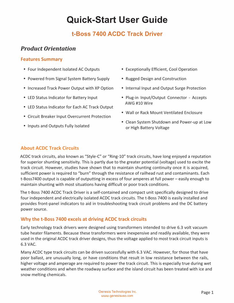
About ACDC Track CircuitsACDC track circuits, also known as “Style-C” or “Ring-10” track circuits, have long enjoyed a reputationfor superior shunting sensitivity. This is partly due to the greater potential (voltage) used to excite thetrack circuit. However, studies have shown that to maintain shunting continuity once it is acquired,sufficient power is required to “burn” through the resistance of railhead rust and contaminants. Eacht-Boss7400 output is capable of outputting in excess of four amperes at full power – easily enough tomaintain shunting with most situations having difficult or poor track conditions.
The t-Boss 7400 ACDC Track Driver is a self-contained and compact unit specifically designed to drivefour independent and electrically isolated ACDC track circuits. The t-Boss 7400 is easily installed andprovides front-panel indicators to aid in troubleshooting track circuit problems and the DC batterypower source.
Why the t-Boss 7400 excels at driving ACDC track circuitsEarly technology track drivers were designed using transformers intended to drive 6.3 volt vacuumtube heater filaments. Because these transformers were inexpensive and readily available, they wereused in the original ACDC track driver designs, thus the voltage applied to most track circuit inputs is6.3 VAC.
Many ACDC type track circuits can be driven successfully with 6.3 VAC. However, for those that havepoor ballast, are unusually long, or have conditions that result in low resistance between the rails,higher voltage and amperage are required to power the track circuit. This is especially true during wetweather conditions and when the roadway surface and the island circuit has been treated with ice andsnow melting chemicals.
� Four Independent Isolated AC Outputs
� Powered from Signal System Battery Supply
� Increased Track Power Output with XP Option
� LED Status Indicator for Battery Input
� LED Status Indicator for Each AC Track Output
� Circuit Breaker Input Overcurrent Protection
� Inputs and Outputs Fully Isolated
� Exceptionally Efficient, Cool Operation
� Rugged Design and Construction
� Internal Input and Output Surge Protection
� Plug-in Input/Output Connector - AcceptsAWG #10 Wire
� Wall or Rack Mount Ventilated Enclosure
� Clean System Shutdown and Power-up at Lowor High Battery Voltage
Quick Start User Guide t-Boss 7400 ACDC Track Driver
Genesis Technologies Inc.www.genesisusa.com
Page 2
The t-Boss 7400 ACDC Track Driver is available in two versions:
� SP (standard power) - each output is approximately 7.5 Volts AC with 3 Amp output load (12.6 VDCinput).
� XP (extra power) - each output is approximately 10.2 Volts AC with 3 Amp output load (12.6 VDCinput).
Compared to early technology track drivers, the t-Boss 7400SP can provide about 16% greater drivingcapability whereas the t-Boss 7400XP can provide about 34% greater driving capability.
t-Boss 7400 FamiliarizationThe t-Boss 7400 ACDC Track Driver is self-contained in a durable, compact steel enclosure. It is easilymounted on the equipment wall of a signal bungalow or cabinet. For rack mounting, an adapter plateis available for standard rack hole spacing. All wiring connections are made via a single 10-positionconnector that requires no crimp terminals – simply strip the wire, insert into the connector receiverclamp and tighten the wire-clamp screw.
The DC power input circuit breaker is intended to disconnect the unit from the DC battery supply ifconnected improperly or an internal short-circuit should occur. Please note however, the circuitbreaker cannot always act fast enough to prevent damage to the unit if it is connected improperly.
The t-Boss 7400 includes secondary power surge protection for the 12VDC input and each of the fourtrack circuit outputs.
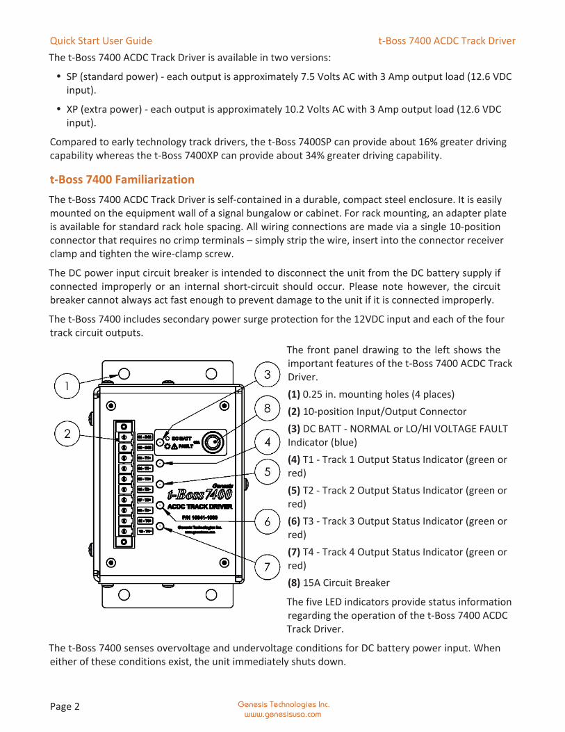
The front panel drawing to the left shows theimportant features of the t-Boss 7400 ACDC TrackDriver.(1) 0.25 in. mounting holes (4 places)(2) 10-position Input/Output Connector(3) DC BATT - NORMAL or LO/HI VOLTAGE FAULTIndicator (blue)(4) T1 - Track 1 Output Status Indicator (green orred)(5) T2 - Track 2 Output Status Indicator (green orred)(6) T3 - Track 3 Output Status Indicator (green orred)(7) T4 - Track 4 Output Status Indicator (green orred)(8) 15A Circuit Breaker
The five LED indicators provide status informationregarding the operation of the t-Boss 7400 ACDCTrack Driver.
The t-Boss 7400 senses overvoltage and undervoltage conditions for DC battery power input. Wheneither of these conditions exist, the unit immediately shuts down.
Quick Start User Guide t-Boss 7400 ACDC Track Driver
Genesis Technologies Inc.www.genesisusa.com
Page 3
The purpose of sensing overvoltage or undervoltage and ceasing operation when such conditions existis to avoid unpredictable operation when input power is outside the specified operating parameters.The Genesis t-Boss 7400 provides “clean” shutdown and power-up under all conditions. For example,should the battery DC input voltage drop below 8.5 VDC, the system immediately shuts down andremains shut down until the battery voltage recovers to 9.5 VDC. This minimizes the possibility oferratic signal operation and “gate-pumping” where the signals and gates repeatedly cycle between ONand OFF, resulting in much confusion to motorists and the risk of damage to vehicles and to the gatearms.
The track output status LEDs provide indications that reflect the status of each track circuit; normalnon-shunted, normal shunted, open, reversed polarity, near overcurrent threshold and overcurrent.These LED indicators are primarily intended to aid in troubleshooting track circuit problems. A morein-depth description is included in the following section, “Using the t-Boss 7400 Front Panel Indicators.”
Application
When and where to use ACDC Track CircuitsACDC track circuits are well suited where poor rail-wheel shunting for signal operation is expected orhas been experienced due to infrequent train traffic, excess railhead rust and/or contamination, orlightweight equipment. They are best suited for rail-highway grade crossings where trains are travelingat or about the same speed and do not stop within the approach circuit before entering the island.
ACDC track circuits are not suitable for signalized crossings where trains or rolling stock are parked orstopped within the approaches and the signals are required to recover. Also, they must not be overlaidnor can they be an overlay or wrap with other types of track circuits such as those used with motionsensors, grade crossing predictors, coded track circuits and other types of track circuits commonly usedin North America.
Using the t-Boss 7400 Front Panel IndicatorsFont panel indicator LEDs are intended to help troubleshoot problems with the B12 DC battery inputand the T1, T2, T3 and T4 track circuit outputs and track circuits.
When the t-Boss 7400 is initially powered-up, the LED Front Panel Indicators cycle through a self-test. Ifthe battery voltage is within the permissible operating range, all track outputs are then powered up.
DC BATT – NORMAL OR LO/HI VOLTAGE FAULT INDICATOR
A single blue LED indicator shows the status of the battery input voltage to the t-Boss 7400.
� ON continuously - DC battery input voltage is within normal operating limits.
� FLASHING slowly - DC battery input voltage is near either the low or high acceptable limits oper-ating threshold.
� STROBED1 - DC battery input voltage is below or above allowable operating limits (system is shut-down and all track outputs are OFF).
Quick Start User Guide t-Boss 7400 ACDC Track Driver
Genesis Technologies Inc.www.genesisusa.com
Page 4
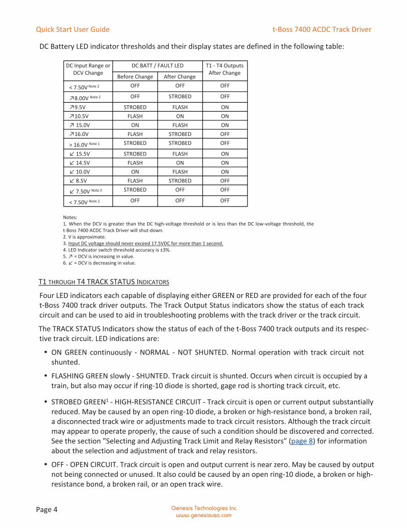
DC Battery LED indicator thresholds and their display states are defined in the following table:
Notes:1. When the DCV is greater than the DC high-voltage threshold or is less than the DC low-voltage threshold, thet-Boss 7400 ACDC Track Driver will shut-down.2. V is approximate.3. Input DC voltage should never exceed 17.5VDC for more than 1 second.4. LED Indicator switch threshold accuracy is ±3%.5. ↗ = DCV is increasing in value.6. ↙ = DCV is decreasing in value.
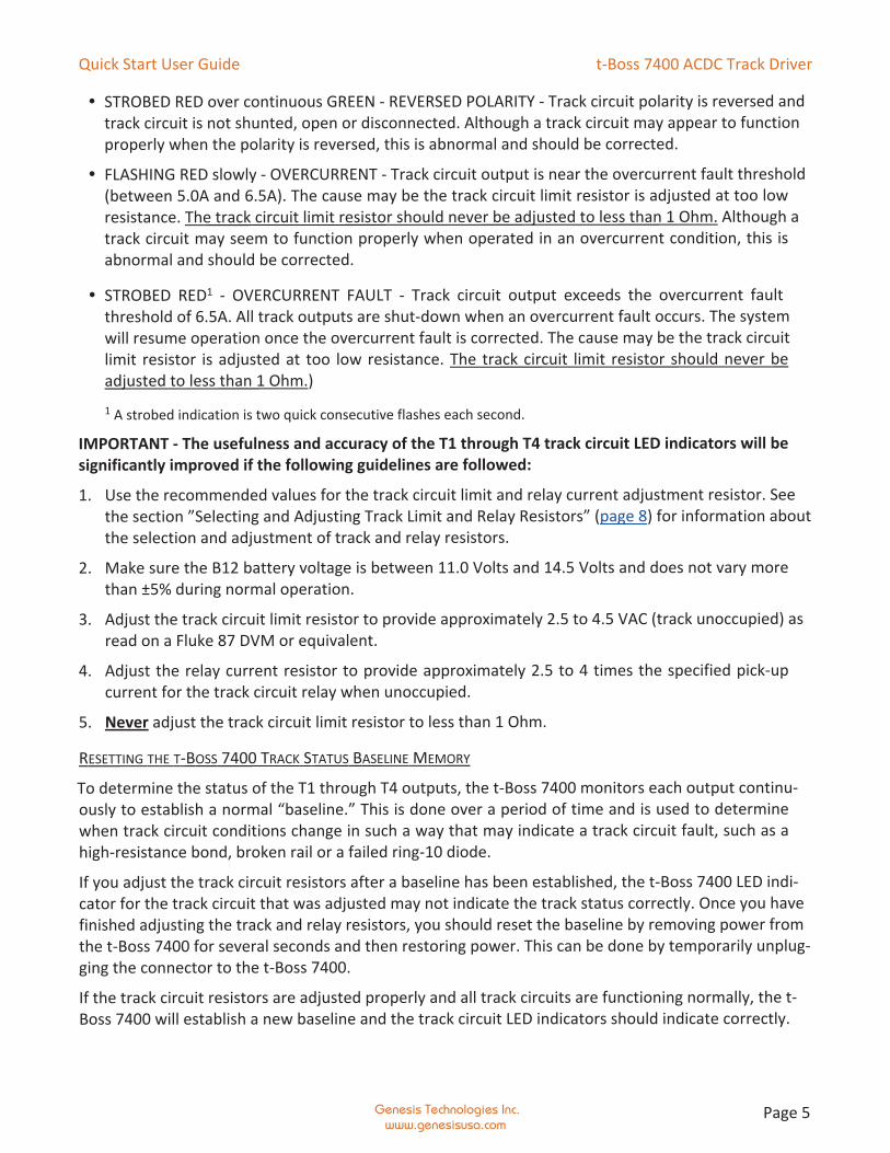
T1 THROUGH T4 TRACK STATUS INDICATORS
Four LED indicators each capable of displaying either GREEN or RED are provided for each of the fourt-Boss 7400 track driver outputs. The Track Output Status indicators show the status of each trackcircuit and can be used to aid in troubleshooting problems with the track driver or the track circuit.
The TRACK STATUS Indicators show the status of each of the t-Boss 7400 track outputs and its respec-tive track circuit. LED indications are:
� ON GREEN continuously - NORMAL - NOT SHUNTED. Normal operation with track circuit notshunted.
� FLASHING GREEN slowly - SHUNTED. Track circuit is shunted. Occurs when circuit is occupied by atrain, but also may occur if ring-10 diode is shorted, gage rod is shorting track circuit, etc.
� STROBED GREEN1 - HIGH-RESISTANCE CIRCUIT - Track circuit is open or current output substantiallyreduced. May be caused by an open ring-10 diode, a broken or high-resistance bond, a broken rail,a disconnected track wire or adjustments made to track circuit resistors. Although the track circuitmay appear to operate properly, the cause of such a condition should be discovered and corrected.See the section ”Selecting and Adjusting Track Limit and Relay Resistors” (page 8) for informationabout the selection and adjustment of track and relay resistors.
� OFF - OPEN CIRCUIT. Track circuit is open and output current is near zero. May be caused by outputnot being connected or unused. It also could be caused by an open ring-10 diode, a broken or high-resistance bond, a broken rail, or an open track wire.
DC Input Range orDCV Change
DC BATT / FAULT LED T1 - T4 OutputsAfter ChangeBefore Change After Change
< 7.50V Note 2 OFF OFF OFF
↗8.00V Note 2 OFF STROBED OFF
↗9.5V STROBED FLASH ON↗10.5V FLASH ON ON↗ 15.0V ON FLASH ON↗16.0V FLASH STROBED OFF
> 16.0V Note 1 STROBED STROBED OFF
↙ 15.5V STROBED FLASH ON↙ 14.5V FLASH ON ON↙ 10.0V ON FLASH ON↙ 8.5V FLASH STROBED OFF
↙ 7.50V Note 2 STROBED OFF OFF
< 7.50V Note 2 OFF OFF OFF
Quick Start User Guide t-Boss 7400 ACDC Track Driver
Genesis Technologies Inc.www.genesisusa.com
Page 5
� STROBED RED over continuous GREEN - REVERSED POLARITY - Track circuit polarity is reversed andtrack circuit is not shunted, open or disconnected. Although a track circuit may appear to functionproperly when the polarity is reversed, this is abnormal and should be corrected.
� FLASHING RED slowly - OVERCURRENT - Track circuit output is near the overcurrent fault threshold(between 5.0A and 6.5A). The cause may be the track circuit limit resistor is adjusted at too lowresistance. The track circuit limit resistor should never be adjusted to less than 1 Ohm. Although atrack circuit may seem to function properly when operated in an overcurrent condition, this isabnormal and should be corrected.
� STROBED RED1 - OVERCURRENT FAULT - Track circuit output exceeds the overcurrent faultthreshold of 6.5A. All track outputs are shut-down when an overcurrent fault occurs. The systemwill resume operation once the overcurrent fault is corrected. The cause may be the track circuitlimit resistor is adjusted at too low resistance. The track circuit limit resistor should never beadjusted to less than 1 Ohm.)
1 A strobed indication is two quick consecutive flashes each second.
IMPORTANT - The usefulness and accuracy of the T1 through T4 track circuit LED indicators will besignificantly improved if the following guidelines are followed:
1. Use the recommended values for the track circuit limit and relay current adjustment resistor. Seethe section ”Selecting and Adjusting Track Limit and Relay Resistors” (page 8) for information aboutthe selection and adjustment of track and relay resistors.
2. Make sure the B12 battery voltage is between 11.0 Volts and 14.5 Volts and does not vary morethan ±5% during normal operation.
3. Adjust the track circuit limit resistor to provide approximately 2.5 to 4.5 VAC (track unoccupied) asread on a Fluke 87 DVM or equivalent.
4. Adjust the relay current resistor to provide approximately 2.5 to 4 times the specified pick-upcurrent for the track circuit relay when unoccupied.
5. Never adjust the track circuit limit resistor to less than 1 Ohm.
RESETTING THE T-BOSS 7400 TRACK STATUS BASELINE MEMORY
To determine the status of the T1 through T4 outputs, the t-Boss 7400 monitors each output continu-ously to establish a normal “baseline.” This is done over a period of time and is used to determinewhen track circuit conditions change in such a way that may indicate a track circuit fault, such as ahigh-resistance bond, broken rail or a failed ring-10 diode.
If you adjust the track circuit resistors after a baseline has been established, the t-Boss 7400 LED indi-cator for the track circuit that was adjusted may not indicate the track status correctly. Once you havefinished adjusting the track and relay resistors, you should reset the baseline by removing power fromthe t-Boss 7400 for several seconds and then restoring power. This can be done by temporarily unplug-ging the connector to the t-Boss 7400.
If the track circuit resistors are adjusted properly and all track circuits are functioning normally, the t-Boss 7400 will establish a new baseline and the track circuit LED indicators should indicate correctly.
Quick Start User Guide t-Boss 7400 ACDC Track Driver
Genesis Technologies Inc.www.genesisusa.com
Page 6
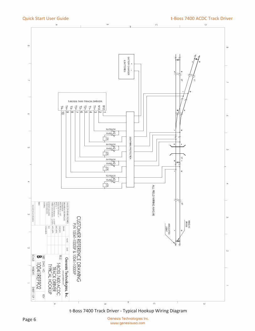
t-Boss 7400 Track Driver - Typical Hookup Wiring Diagram
Quick Start User Guide t-Boss 7400 ACDC Track Driver
Genesis Technologies Inc.www.genesisusa.com
Page 7
Installation
Overall PreparationTo better understand the requirements of ACDC track circuits, please refer to the t-Boss 7400 Installa-tion Diagram (page 6).
Each track circuit must be:
� isolated from adjacent track circuits (including non-circuited track) using suitable insulated joints inboth rails;
� free from low resistance paths between the rails such as non-insulated gauge rods, non-insulatedmetalized frames in roadway crossing surfaces and very poor ballast; (The t-Boss 7400 can drivetrack circuits that have a rail-to-rail resistance of less than two Ohms. However, a resistanceexceeding ten Ohms will yield much better results.)
� electrically bonded at all non-insulated rail joints using one or two bonds from one rail to the next;
� equipped with a suitable and properly installed diode (also known as a ring-10 diode) at the end ofthe track circuit opposite from where the track feed wires are connected;
� connected from the rails to the field connections in the case or bungalow using wire no smallerthan AWG #6.
� protected by appropriate primary lightning protection (warranty does not cover lightning damage);
� equipped with adjustable track limit and a relay resistors suitable for the track driver being usedand the overall application; and
� equipped with a track driver such as the t-Boss 7400XP or t-Boss 7400SP.
Appropriate primary lightning protection is also required for the 12VDC battery input.
Wiring and ConnectionsSee separate (11” x 17” drawing provided with each unit) wiring diagram for proper hookup or refer topage 6.
Track circuits should be connected such that polarity and phase are opposite to those of adjacent trackcircuits. This helps to ensure that activation of the signals will occur should both insulated joints failand the circuits become shorted to each other.
Opposite phase and polarity of adjacent track circuits is accomplished by installing ring-10 track diodeswith opposite polarity to those of adjacent circuits. Also, the t-Boss 7400 track output labeled as “+”should be connected to the positive side of the circuit. This is best understood by examining theprovided wiring diagram and using it as a guide for your wiring hook-up.
When wiring the t-Boss 7400 plug-in connector, MAKE CERTAIN your wiring is correct BEFORE PLUG-GING IN THE CONNECTOR. Damage to the t-Boss 7400 ACDC Track Driver caused by improper hookupis not covered by the warranty.
The front-panel connector should have ONLY ONE WIRE PER INSERTION POINT. It is not designed tohold securely more than one wire.
Make sure to use wire of adequate size for the current it must carry. The B12 and N12 inputs may berequired to carry up to 15 amperes under certain conditions. Each output may see currents up to 6.5
Quick Start User Guide t-Boss 7400 ACDC Track Driver
Genesis Technologies Inc.www.genesisusa.com
Page 8
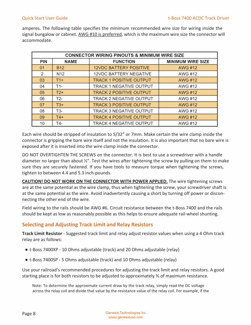
amperes. The following table specifies the minimum recommended wire size for wiring inside thesignal bungalow or cabinet. AWG #10 is preferred, which is the maximum wire size the connector willaccommodate.
Each wire should be stripped of insulation to 5/32” or 7mm. Make certain the wire clamp inside theconnector is gripping the bare wire itself and not the insulation. It is also important that no bare wire isexposed after it is inserted into the wire clamp inside the connector.
DO NOT OVERTIGHTEN THE SCREWS on the connector. It is best to use a screwdriver with a handlediameter no larger than about ½”. Test the wires after tightening the screw by pulling on them to makesure they are securely fastened. If you have tools to measure torque when tightening the screws,tighten to between 4.4 and 5.3 inch-pounds.
CAUTION! DO NOT WORK ON THE CONNECTOR WITH POWER APPLIED. The wire tightening screwsare at the same potential as the wire clamp, thus when tightening the screw, your screwdriver shaft isat the same potential as the wire. Avoid inadvertently causing a short by turning off power or discon-necting the other end of the wire.
Field wiring to the rails should be AWG #6. Circuit resistance between the t-Boss 7400 and the railsshould be kept as low as reasonably possible as this helps to ensure adequate rail-wheel shunting.
Selecting and Adjusting Track Limit and Relay ResistorsTrack Limit Resistor - Suggested track limit and relay adjust resistor values when using a 4 Ohm trackrelay are as follows:
● t-Boss 7400XP - 10 Ohms adjustable (track) and 20 Ohms adjustable (relay)
● t-Boss 7400SP - 5 Ohms adjustable (track) and 10 Ohms adjustable (relay)
Use your railroad’s recommended procedures for adjusting the track limit and relay resistors. A goodstarting place is for both resistors to be adjusted to approximately ⅔ of maximum resistance.
Note: To determine the approximate current draw by the track relay, simply read the DC voltageacross the relay coil and divide that value by the resistance value of the relay coil. For example, if the
CONNECTOR WIRING PINOUTS & MINIMUM WIRE SIZEPIN NAME FUNCTION MINIMUM WIRE SIZE01 B12 12VDC BATTERY POSITIVE AWG #122 N12 12VDC BATTERY NEGATIVE AWG #12
03 T1+ TRACK 1 POSITIVE OUTPUT AWG #1204 T1- TRACK 1 NEGATIVE OUTPUT AWG #1205 T2+ TRACK 2 POSITIVE OUTPUT AWG #1206 T2- TRACK 2 NEGATIVE OUTPUT AWG #1207 T3+ TRACK 3 POSITIVE OUTPUT AWG #1208 T3- TRACK 3 NEGATIVE OUTPUT AWG #1209 T4+ TRACK 4 POSITIVE OUTPUT AWG #1210 T4- TRACK 4 NEGATIVE OUTPUT AWG #12
Quick Start User Guide t-Boss 7400 ACDC Track Driver
Genesis Technologies Inc.www.genesisusa.com
Page 9
DC voltage reads 1.0 VDC and the relay coil resistance is 4 Ohms, then 1.0 ÷ 4 = 0.25, or 0.25A (250milliamps).
About Track BallastGood ballast conditions will improve shunting by not absorbing energy provided by the t-Boss 7400ACDC Track Driver that would otherwise be used for good shunting. We recommend that theapproaches be reasonably free from dirt and other contaminants that would otherwise absorb elec-trical energy intended to help with shunting.
Pre-cutover Testing and CutoverOnce you have the t-Boss 7400 ACDC Track Driver operating, check the voltage to the rails. In dryweather conditions with good ballast you should see 2.5 to 4.5VAC, depending on the adjustment ofthe track circuit limit resistor. Remember, the track circuit voltage depends on the following threefactors:
1. Rail to rail resistance as affected by ballast, weather, snow and ice melting chemicals, etc.;
2. Settings of the track circuit limit resistor, and to a lesser extent, the relay current adjustmentresistor;
3. Battery input voltage to the t-Boss.
The following tests should be made before cutover:
1. Complete a disarrangement test as required by your railroad’s procedures;
2. Shunt each track circuit with a zero Ohm shunt then check the respective t-Boss 7400 track outputstatus LED to make sure it is not drawing too much current (LED flashing RED or strobed RED). If itis, correct the problem before continuing. The problem may be the track circuit limit resistor is setat too low resistance;
3. Shunt all approaches and the island using an approved 0.06 Ohm shunt to verify proper signal oper-ation;
4. If possible, watch a train through the approaches and island to verify proper signal operation;
5. Complete any additional tests as required by your railroad or other regulatory agencies.
Quick Start User Guide t-Boss 7400 ACDC Track Driver
Genesis Technologies Inc.www.genesisusa.com
Page 10
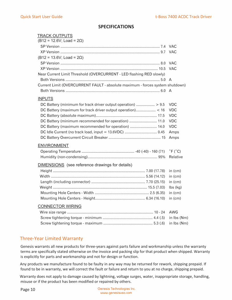
SPECIFICATIONS
TRACK OUTPUTS(B12 = 12.6V; Load = 2Ω)
SP Version ...................................................................................................... 7.4 VACXP Version ...................................................................................................... 9.7 VAC
(B12 = 13.6V; Load = 2Ω)SP Version ...................................................................................................... 8.0 VACXP Version .................................................................................................... 10.5 VAC
Near Current Limit Threshold (OVERCURRENT - LED flashing RED slowly) Both Versions ................................................................................................ 5.0 ACurrent Limit (OVERCURRENT FAULT - absolute maximum - forces system shutdown)
Both Versions ................................................................................................ 6.0 A
INPUTSDC Battery (minimum for track driver output operation) ................... > 9.5 VDCDC Battery (maximum for track driver output operation).................... < 16 VDCDC Battery (absolute maximum).............................................................. 17.5 VDCDC Battery (minimum recommended for operation) ............................ 11.0 VDCDC Battery (maximum recommended for operation) ........................... 14.0 VDCDC Idle Current (no track load, input = 13.6VDC) ................................. 0.45 AmpsDC Battery Overcurrent Circuit Breaker ..................................................... 15 Amps
ENVIRONMENTOperating Temperature ...................................................... -40 (-40) - 160 (71) ˚F (˚C)Humidity (non-condensing)....................................................................... 95% Relative
DIMENSIONS (see reference drawings for details)Height .............................................................................................. 7.00 (17.78) in (cm)Width ................................................................................................ 5.56 (14.12) in (cm)Length (including connector) ....................................................... 7.70 (25.15) in (cm)Weight ................................................................................................ 15.5 (7.03) lbs (kg)Mounting Hole Centers - Width ....................................................... 2.5 (6.35) in (cm)Mounting Hole Centers - Height................................................... 6.34 (16.10) in (cm)
CONNECTOR WIRINGWire size range ........................................................................................ 10 - 24 AWGScrew tightening torque - minimum ................................................... 4.4 (.5) in lbs (Nm)Screw tightening torque - maximum .................................................. 5.3 (.6) in lbs (Nm)
Three-Year Limited WarrantyGenesis warrants all new products for three-years against parts failure and workmanship unless the warrantyterms are specifically stated otherwise on the invoice and packing slip for that product when shipped. Warrantyis explicitly for parts and workmanship and not for design or function.
Any products we manufacture found to be faulty in any way may be returned for rework, shipping prepaid. Iffound to be in warranty, we will correct the fault or failure and return to you at no charge, shipping prepaid.
Warranty does not apply to damage caused by lightning, voltage surges, water, inappropriate storage, handling,misuse or if the product has been modified or repaired by others.