Embed Size (px)
Citation preview

Quick Start GuideSuit for S8900-54XC/S8900-64XC
01.08.18

1
Chapter1 Know your switch....................................................................................................................................................2
1.1 S8900-54XC/S8900-64XC...............................................................................................................................2
1.2 Mount switch onto the rack...........................................................................................................................2
1.3 Interface description of S8900-54XC/S8900-64XC.........................................................................................3
1.4 LED description of S8900-54XC/S8900-64XC..................................................................................................3
1.4.1 System LED.............................................................................................................................................................................4
1.4.2 Port LED........................................................................................................................................................................................ 4
2. Manage Your Switch................................................................................................................................................5
2.1 Manage switch through console port............................................................................................................5
2.1.1 Connect switch console port to client.........................................................................................................................5
2.1.2 Connect to your switch.....................................................................................................................................................6
2.1.3 Login your switch................................................................................................................................................................6
2.2 Manage switch through OOB Ethernet port..................................................................................................7
2.2.1 Connect switch OOB Ethernet port to client............................................................................................................7
2.2.2 Configure the IP address of switch OOB Ethernet port......................................................................................8
2.2.3 Login your switch................................................................................................................................................................8
3. Shell Brief Introduction............................................................................................................................................8
3.1 Command Modes...........................................................................................................................................8
3.2 Command Completion and Abbreviation.......................................................................................................9
3.3 CLI Error Messages.......................................................................................................................................10
2
1 Know your switch
1.1S8900-54XC/S8900-64XC
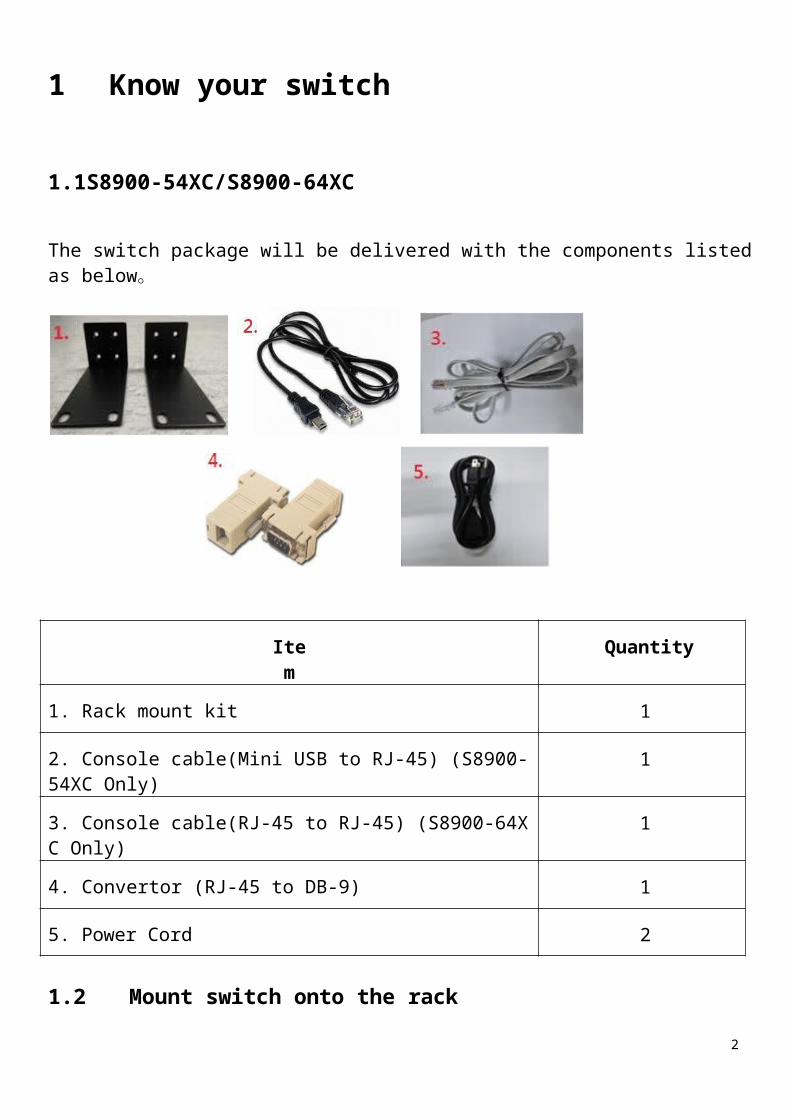
The switch package will be delivered with the components listed as below。
Item Quantity
1. Rack mount kit 1
2. Console cable(Mini USB to RJ-45) (S8900-54XC Only) 1
3. Console cable(RJ-45 to RJ-45) (S8900-64XC Only) 1
4. Convertor (RJ-45 to DB-9) 1
5. Power Cord 2
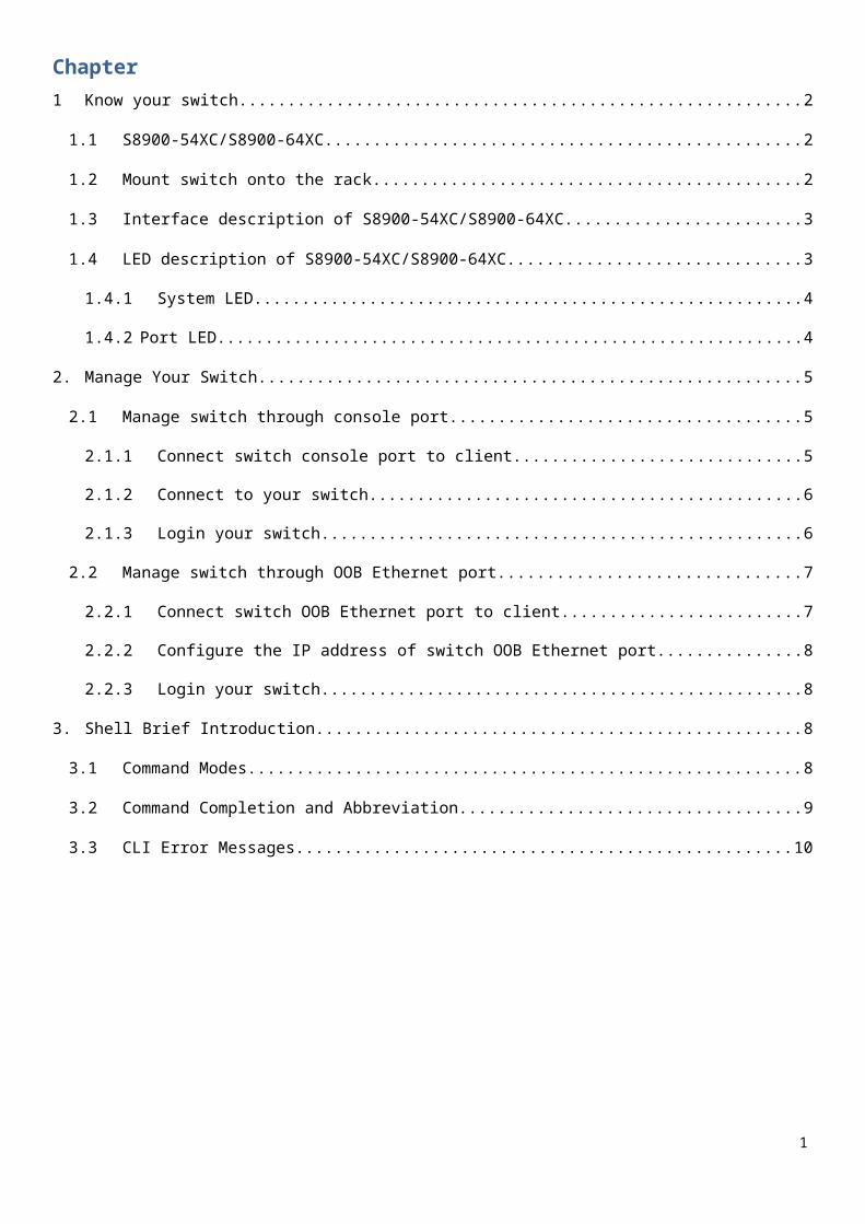
1.2Mount switch onto the rack
S8900-54XC/S8900-64XC is suitable for 19 inch rack. Fasten the rack mount kit in the accessory pack before mounting it onto the position on the rack. Secure the device with screwing the screw on the rack.

3
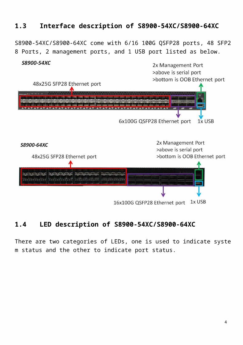
1.3Interface description of S8900-54XC/S8900-64XC
S8900-54XC/S8900-64XC come with 6/16 100G QSFP28 ports, 48 SFP28 Ports, 2 management ports, and 1 USB port listed as below.
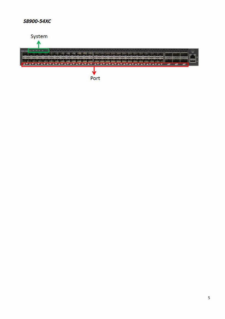
1.4LED description of S8900-54XC/S8900-64XC
There are two categories of LEDs, one is used to indicate system status and the other to indicate port status.
4
1.4.1 System LED
System LED indicates the operation status of PSU, FAN, and System.
LED name Color Meaning
PSUGreen PSU work wellOrange PSU not workGrey PSU not inserted
FANGreen FAN work wellOrange FAN not work
STATGreen System work wellOrange System not work
5
1.4.2 Port LED
Port LED indicated the speed of link and state of transmission.
LED Name Color Meaning
Port Number
Green Link up in highest speed(100G)Orange
Link up in non-highest speed(40G、25G、10G)
Grey Link down
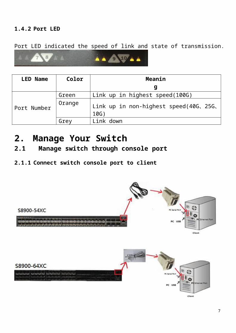
2. Manage Your Switch2.1Manage switch through console port
2.1.1 Connect switch console port to client

6
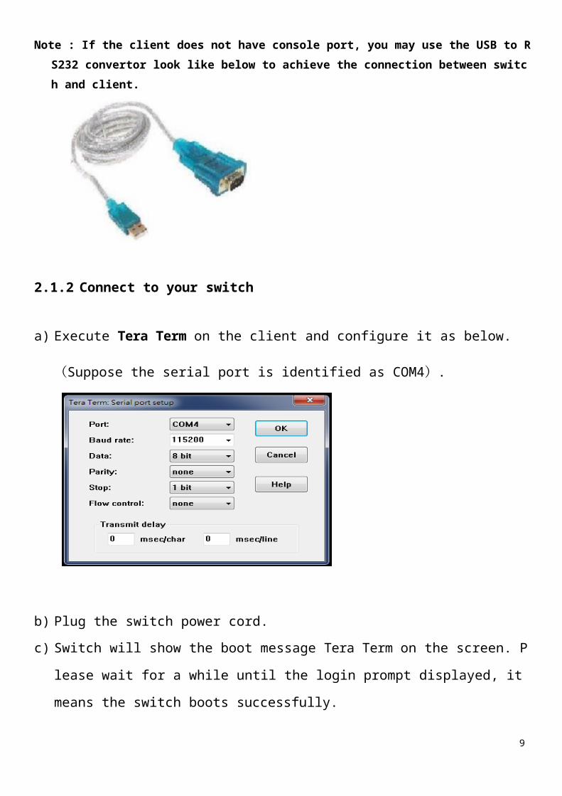
Note : If the client does not have console port, you may use the USB to RS232 convertor look like
below to achieve the connection between switch and client.
2.1.2 Connect to your switch
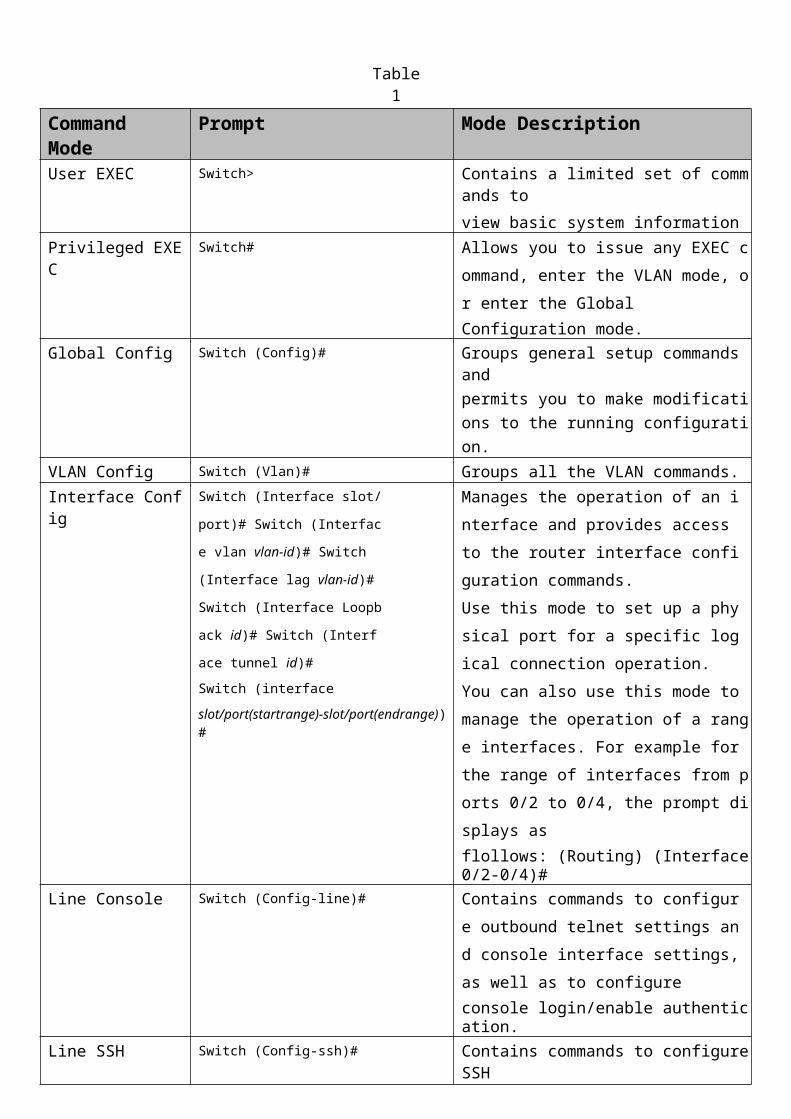
a) Execute Tera Term on the client and configure it as below.(Suppose the serial port
is identified as COM4).
b) Plug the switch power cord.
c) Switch will show the boot message Tera Term on the screen. Please wait for a while
until the login prompt displayed, it means the switch boots successfully.
7
2.1.3 Login to your switch true console port
Please input the account and password. By default, the account is admin and password is admin.
After login Ubuntu, execute “sudo icos-cli” to enter the switch command line shell .
2.2Manage switch through OOB Ethernet port
2.2.1 Connect switch OOB Ethernet port to client.

2.2.2 Configure the IP address of switch OOB Ethernet port
By default S8900-54XC OOB Ethernet management port configured as DHCP client. If you want to configure the IP address manually, you have to modify network configuration. Here comes an example.
#serviceport protocol none#serviceport ip <ipaddr> <netmask> <gateway> #show serviceport
2.2.1 Login to your switch true MGMT port Use the SSH client to login your switch after set up the IP address.For ICOS CLI connection please use SSH port 22, login admin, empty password.For Linux shell connection please use port 2233, login admin, password admin.
3. Shell Brief Introduction3.1 Command Modes
The CLI groups commands into modes according to the command function. Each of the command mod
es supports specific commands. The commands in one mode are not available until you switch to that p
articular mode, with the exception of the User EXEC mode commands. You can execute the User EXEC
mode commands in the Privileged EXEC mode.
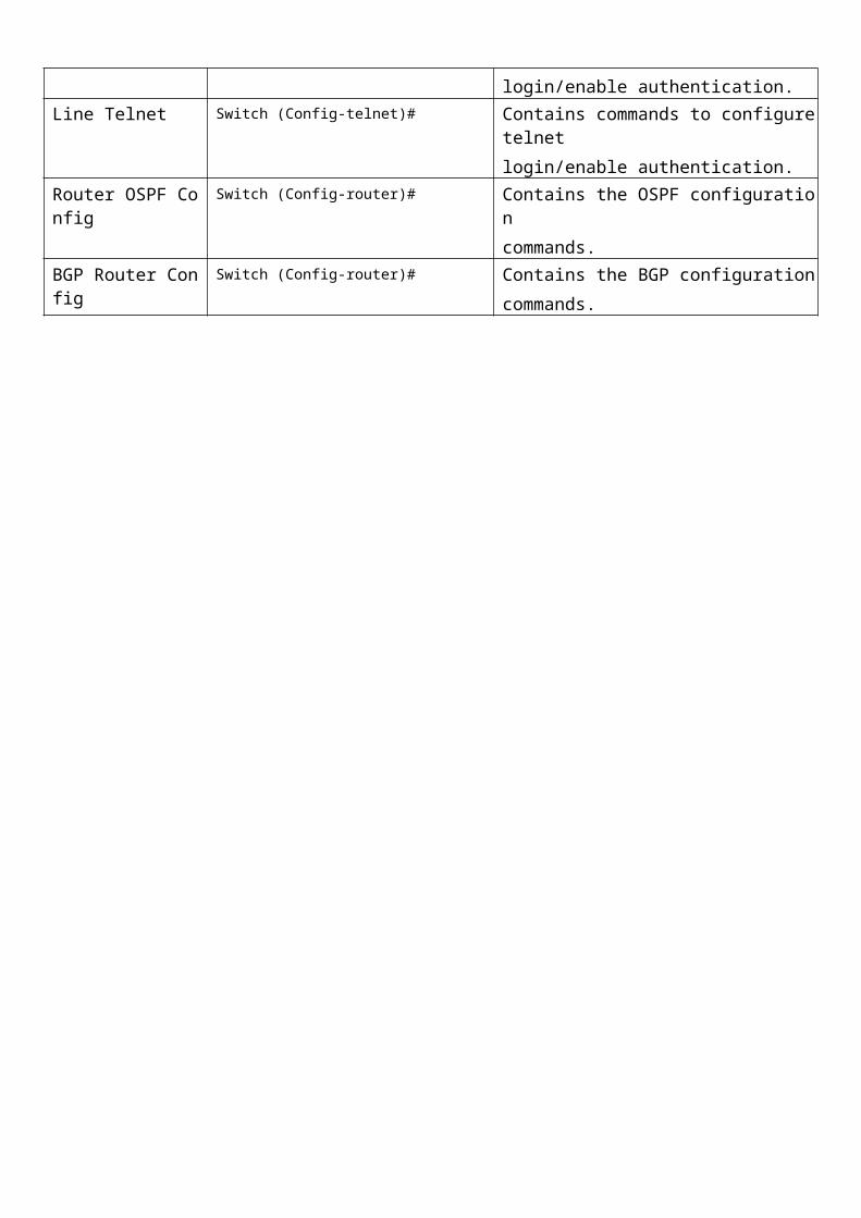
The command prompt changes in each command mode to help you identify the current mode. The tab
le describes the command mods an the prompts visible in that mode

Table 1
CommandMode
Prompt Mode Description
User EXEC Switch> Contains a limited set of commands to
view basic system information
Privileged EXEC Switch# Allows you to issue any EXEC command, e
nter the VLAN mode, or enter the Global
Configuration mode.
Global Config Switch (Config)# Groups general setup commands and
permits you to make modifications to the
running configuration.
VLAN Config Switch (Vlan)# Groups all the VLAN commands.
Interface Config Switch (Interface slot/port)# S
witch (Interface vlan vlan-id)# S
witch (Interface lag vlan-id)# S
witch (Interface Loopback id)#
Switch (Interface tunnel id)#
Switch (interface
slot/port(startrange)-slot/port(endrange))#
Manages the operation of an interface an
d provides access to the router interface
configuration commands.
Use this mode to set up a physical port fo
r a specific logical connection operation.
You can also use this mode to manage the
operation of a range interfaces. For examp
le for the range of interfaces from ports 0/
2 to 0/4, the prompt displays as
flollows: (Routing) (Interface 0/2-0/4)#
Line Console Switch (Config-line)# Contains commands to configure outbou
nd telnet settings and console interface s
ettings, as well as to configure
console login/enable authentication.
Line SSH Switch (Config-ssh)# Contains commands to configure SSH
login/enable authentication.
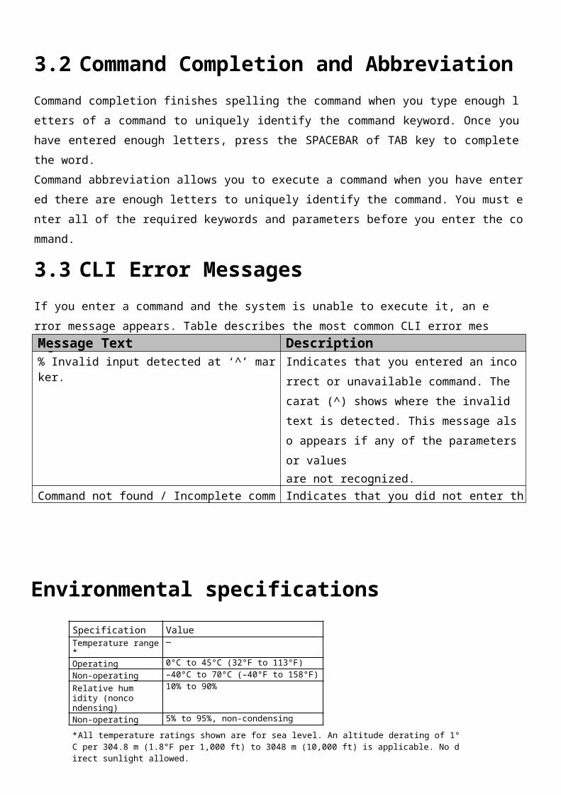
Line Telnet Switch (Config-telnet)# Contains commands to configure telnet
login/enable authentication.
Router OSPF Config Switch (Config-router)# Contains the OSPF configuration
commands.
BGP Router Config Switch (Config-router)# Contains the BGP configuration
commands.

3.2 Command Completion and Abbreviation
Command completion finishes spelling the command when you type enough letters of a command to
uniquely identify the command keyword. Once you have entered enough letters, press the SPACEBAR
of TAB key to complete the word.
Command abbreviation allows you to execute a command when you have entered there are enough let
ters to uniquely identify the command. You must enter all of the required keywords and parameters b
efore you enter the command.
3.3 CLI Error Messages
If you enter a command and the system is unable to execute it, an error message appears. Table
describes the most common CLI error messages.
Environmental specifications
Specification ValueTemperature range* —
Operating 0°C to 45°C (32°F to 113°F)
Non-operating –40°C to 70°C (–40°F to 158°F)
Relative humidity (noncondensing)
10% to 90%
Non-operating 5% to 95%, non-condensing
* All temperature ratings shown are for sea level. An altitude derating of 1°C per 304.8 m (1.8°F per 1,000 ft) to 3048 m (10,000 ft) is applicable. No direct sunlight allowed.
Mechanical specificationsSpecification ValueHeight 44 mm
Depth 406.4 mm
Width 440 mm
Gross Weight Max 11.78 kg
Message Text Description% Invalid input detected at ‘^’ marker. Indicates that you entered an incorrect or unavai
lable command. The carat (^) shows where the i
nvalid text is detected. This message also appear
s if any of the parameters or values
are not recognized.
Command not found / Incomplete command.
Use ? to list commands.
Indicates that you did not enter the required
keyword or values.
Ambiguous command Indicates that you did not enter enough letters to
uniquely identify the command.

Input requirementsSpecification Value
Rated Line Voltage 100-240VAC
Rated Current 7A/3.5A
Rated Frequency 50/60Hz
European Union regulatory noticeProducts bearing the CE marking comply with one or more of the following EU Directives as may be applicable:
Low Voltage Directive 2014/35/EC
EMC Directive 2014/30/EU
Ecodesign Directive 2009/125/EC
RoHS Directive 2011/65/EU
Compliance with these directives is assessed using applicable European Harmonised Standards.
The full Declaration of Conformity can be found at the following website: http://www.tradedx.eu/certificates.
ContactTradeDX s. r. o.Karlov 245, 284 01 Kutná Hora Czech RepublicTel.: +420737264041, Web: tradedx.eu

Warnings & Safety
Important safety and compliance informationBe sure to read all caution and warning statements in this documentation before performing any procedure in this user manual. To avoid potential problems, ALWAYS read the warnings, cautionary and safety information that comes with device documentation before removing, replacing, reseating or modifying system components.
Safety precautionsObserve the following safety precautions when setting up equipment:
Follow all cautions and instructions marked on the equipment.
Ensure that the voltage and frequency of power source match the voltage and frequency inscribed on the equipment’s electrical rating label.
Never push objects of any kind through openings in the equipment. Dangerous voltages may be present.
Conductive foreign objects could produce a short circuit that could cause fire, electric shock, or damage to your equipment.
Safety Instructions1. Please read these safety instructions carefully.
2. Please keep this Manual for later reference.
3. Please disconnect this equipment from AC outlet before cleaning. Don’t use liquid or sprayed detergent for cleaning. Use moist sheet or cloth for cleaning.
4. For pluggable equipment, the socket-outlet must be installed near the equipment and must be easily accessible.
5. Please keep this equipment from humidity.
6. Place this equipment on a safe reliable surface when installing. A drop or fall could cause injury.
7. Enclosure openings are for air circulation and protect the equipment from overheating. DO NOT COVER THE OPENINGS.
8. Make sure the voltage of the power source matches rated voltages.
9. Place the power cord so that it won't be stepped on or tripped over. Do not place anything on top of the power cord.
10. All cautions and warnings on the equipment should be noted.
11. If the equipment is not used for a long time, disconnect the equipment from outlet to avoid damage to the system by transient voltages.
12. Do not spill liquids onto equipment; this may cause fire or electrical shock.
13. Never open the equipment. For safety reasons, the equipment should only be opened by qualified service personnel.
14. If any of the following situations arises, have the equipment checked by qualified service:
a. The power cord or plug is damaged.
b. Liquid seeped into the equipment.
c. The equipment has been exposed to moisture.
d. The equipment does not work well or operation does not match behavior described in user's manual.
e. The equipment has been dropped or damaged.
f. The equipment has obvious signs of damage.
15. DO NOT LEAVE THIS EQUIPMENT IN AN ENVIRONMENT WHERE TEMPERATURES EXCEED 70 °C (158 °F); IT MAY DAMAGE THE EQUIPMENT.
SymbolsThe following symbols may be placed on the equipment to indicate the presence of potential hazardous condition.
This symbol indicates the presence of hazardous energy circuits or electric shock hazards. Refer all servicing to qualified personnel.WARNING: Do not open this enclosure to reduce the risk of injury from electric shock hazards. Refer all maintenance, upgrades and servicing to qualified personnel.
CAUTION: There is a risk of personal injury and equipment damage. Follow the instructions.
CAUTION: The following label indicates sharp edges, corners or joints nearby.
CAUTION: The following label indicates a hot surface nearby.Hot surface. Avoid contact. Surfaces are hot and may cause personal injury if touched. WARNING: Allow the surface to cool before touching to reduce the risk of injury from a hot component.
CAUTION: This symbol indicates the presence of electric shock hazards. The area contains no user or field serviceable parts. Do not open for any reason.WARNING: Do not open this enclosure to reduce the risk of injury from electric shock hazards.
CAUTION: This symbol indicates hazardous moving parts are nearby.
CAUTION: When replacing the lithium battery, use only the TradeDX spare battery designated for this product. If your system has a module containing a lithium battery, replace it only with the same module type made by the same manufacturer. The battery contains lithium and can explode if not properly used, handled, or disposed of.Do not: Throw or immerse into water Heat to more than 100°C (212°F) Repair or disassemble Dispose of the battery as required by local ordinances or regulations.
CAUTION: When laser products (such as CD-ROMs, DVD drives, fiber optic devices, or transmitters) are installed, note the following: Do not remove the covers. Removing the covers of the laser product could result in exposure to
hazardous laser radiation. There are no serviceable parts inside the device. Use of controls or adjustments or performance of procedures other than those specified herein might
result in hazardous radiation exposure.
Some laser products contain an embedded Class 3A or Class 3B laser diode. Note the following. Laser radiation when open. Do not stare into the beam, do not view directly with optical instruments, and avoid direct exposure to the beam.
Class 1 Laser Product
CAUTION: Do not place any object on top of rack-mounted devices.
Safety statementsREAD THIS IMPORTANT SAFETY INFORMATION SECTION. RETURN TO THIS MANUAL FOR REFERENCE. READ THIS SECTION BEFORE SERVICING.
CAUTION:Laser Drive EquipmentThe optical transceiver module in this device is a laser Class 1 product. Ambient OperationThis equipment cannot be operated above an ambient operation temperature of 40 degrees centigrade.Equipment LocationThis equipment can only be accessed by SERVICE PERSONNEL or by USERS who have been instructed about the reasons for the restrictions applied to the location. Access is through the use of a TOOL or lock and key, or other means of security, and is controlled by the authority responsible for the location.
CAUTION: Do not connect the device to any other type of power system to reduce the risk of electric shock.WARNING: This device is suitable for use on an IT power distribution system whose maximum phase-to-phase voltage is 240 V under any distribution fault condition.
Electrical current from power, telephone, and communication cables is hazardous. To avoid a shock hazard: Do not connect or disconnect any cables or perform installation, maintenance, or
reconfiguration of this product during an electrical storm. Connect all power cords to a properly wired and grounded electrical outlet. Connect to properly wired outlets any equipment that will be attached to this product. When possible, use one hand only to connect or disconnect signal cables. Never turn on any equipment when there is evidence of fire, water, or structural damage. Disconnect the attached power cords, telecommunications systems, networks, and modems
before you open the device covers, unless instructed otherwise in the installation and configuration procedures.
Connect and disconnect cables as described in the following table when installing, moving, or opening covers on this product or attached devices.
To Connect: To Disconnect:
1 Turn everything OFF.2 First, attach all cables to devices.3 Attach signal cables to connectors.4 Attach power cords to outlet.5 Turn device ON.
1 Turn everything OFF.2 First, remove power cords from outlet.3 Remove signal cables from connectors.4 Remove all cables from devices.
CAUTION: The power control button on the device and the power switch on the power supply do not turn off the electrical current supplied to the device. The device also might have more than one power cord. To remove all electrical current from the device, ensure that all power cords are disconnected from the power source.
CAUTION: Never remove the cover on a power supply or any part that has the following label attached.
Hazardous voltage, current, and energy levels are present inside any component that has this label attached. There are no serviceable parts inside these components. If you suspect a problem with one of these parts, contact a service technician.
Overloading a branch circuit is potentially a fire hazard and a shock hazard under certain conditions. To avoid these hazards, ensure that your system electrical requirements do not exceed branch circuit protection requirements. Refer to the information that is provided with your device for electrical specifications.
Warnings and cautions WARNING: Only authorized trained technicians should attempt to repair this equipment. All troub
leshooting and repair procedures are detailed to allow only subassembly/module-level repair. Because of the complexity of the individual boards and subassemblies, no one should attempt to make repairs at the component level or to make modifications to any printed wiringboard. Improper repairs can create a safety hazard.

WARNING: To reduce the risk of personal injury or damage to the equipment, be sure that: The leveling feet are extended to the floor. The full weight of the rack rests on the leveling feet. The stabilizing feet are attached to the rack if it is a single-rack installation. The racks are coupled together in multiple-rack installations. Only one component is extended at a time. A rack may become unstable if more than one
component is extended for any reason.
WARNING: To reduce the risk of electric shock or damage to the equipment: Do not disable the power cord grounding plug. The grounding plug is an important safety
feature. Plug the power cord into a grounded (earthed) electrical outlet that is easily accessible at all
times. Unplug the power cord from the power supply to disconnect power to the equipment. Do not route the power cord where it can be walked on or pinched by items placed against it.
Pat particular attention to the plug, electrical outlet and the point where the cord extends from the device.
WARNING: To reduce the risk of personal injury or damage to the equipment: Observe local occupation health and safety requirements and guidelines for manual handling. Obtain adequate assistance to lift and stabilize the chassis during installation or removal. The device is unstable when not fastened to the rails. When mounting the device in a rack, remove the power supplies and any other removabl
e module to reduce overall weight of the product.
CAUTION: To properly ventilate the system, at least 7.6cm (3.0 in) of clearance at the front and back of the device should be provided.
CAUTION: The device is designed to be electrically grounded (earthed). Only plug the AC power cord into a properly grounded AC outlet to ensure power operation.
Electrostatic dischargePreventing electrostatic dischargeTo prevent damaging the system, be aware of the precautions to follow when setting up the system or handling parts. A discharge of static electricity from a finger or other conducer may damage system boards or other static-sensitive devices. This type of damage may reduce the life expectancy of the device.
To prevent electrostatic damage:
Avoid hand contact by transporting and storing products in static-safe container.
Keep electrostatic-sensitive parts in their container until they arrive at static-free workstations.
Place parts on a grounded surface before removing from their containers.
Avoid touching pins, leads or circuitry.
Always be properly grounded when touching a static-sensitive component or assembly.

Grounding methods to prevent electrostatic dischargeUse one or more of the following methods when handling or installing electrostatic-sensitive parts:
Use a wrist strap connected by a ground cord to a grounded workstation or computer chassis. Wrist straps are flexible straps with a minimum of 1 mega-ohm +/-10 percent resistance in the ground cords. Wear the strap snug against the skin to provide proper ground.
Use heel straps, toe straps or boot straps at standing workstations. Wear the straps on both feet when standing on conductive floors or dissipating floor mats.
Use conductive field service tools.
Use a portable field service kit with a folding static-dissipating work mat.Have an authorized reseller install the part if any of suggested equipment for proper grounding is not available.
Contact an authorized reseller for more information on static electricity or assistance with product installation.
WARNING: The circuit boards and hard drives contain electronic components that are extremely sensitive to static electricity. Ordinary amounts of static electricity from clothing or the work environment can destroy these components. Wear an antistatic wrist strap when handling the media drive assemblies, circuit boards, processors, DIMMs and PCIe cards. Whenservicing or removing device components, attach an antistatic strap to your wrist and then to a metal area on the device chassis then disconnect the power cord from the device and the wall receptacle. Following this caution equalizes all electrical potentials within the device.