Embed Size (px)
Citation preview
Quick Start Guide
NET´s Software Development Kit
Ple
ase
no
te t
hat
all
dat
a an
d il
lust
rati
on
s ar
e su
bje
ct t
o e
rro
r, c
han
ge a
nd
om
issi
on
s w
ith
ou
t n
oti
ce.
Syn
Vie
w
Rev
. 1.0
2-1
020
14

2 / 79
Ple
ase
no
te t
hat
all
dat
a an
d il
lust
rati
on
s ar
e su
bje
ct t
o e
rro
r, c
han
ge a
nd
om
issi
on
s w
ith
ou
t n
oti
ce.
Sy
nV
iew
Rev
. 1.0
2-1
020
14
Table of Contents Table of Contents ........................................................................................................................................... 2
General information ...................................................................................................................................... 6
Scope of the manual .................................................................................................................................. 6
Related documents .................................................................................................................................... 6
Quick start ..................................................................................................................................................... 7
Connection and configuration of the camera(s) ........................................................................................ 7
GigEpro & GimaGO easy ......................................................................................................... 7
CORSIGHT .............................................................................................................................. 10
SynView installation — quick guide for Windows ................................................................................... 10
Basic camera configuration ..................................................................................................................... 13
Testing camera(s)..................................................................................................................................... 14
What next? .............................................................................................................................................. 17
SynView overview ....................................................................................................................................... 18
Connecting an application with NET cameras ......................................................................................... 18
SynView GenTL Producer ......................................................................................................................... 19
SynView API ............................................................................................................................................. 19
SynView Explorer and SynView Source Code Generator ......................................................................... 20
Industry standards ................................................................................................................................... 23
Licensing information .............................................................................................................................. 23
SynView Explorer in Detail ...................................................................................................................... 24
Connection and disconnection of the camera ......................................................................................... 25
Features ................................................................................................................................................... 27
Beginner-Expert-Guru level ................................................................................................... 28
Help for a feature .................................................................................................................. 29
Device configuration .............................................................................................................. 29
How to find a feature ............................................................................................................ 31
Configuration: Save and Restore ........................................................................................... 32
Acquisition: Start and Stop ...................................................................................................................... 33
Display of images .................................................................................................................................... 34

3 / 79
Ple
ase
no
te t
hat
all
dat
a an
d il
lust
rati
on
s ar
e su
bje
ct t
o e
rro
r, c
han
ge a
nd
om
issi
on
s w
ith
ou
t n
oti
ce.
Sy
nV
iew
Rev
. 1.0
2-1
020
14
Automatic image pre-processing .......................................................................................... 34
Saving acquired image .......................................................................................................... 35
Settings .................................................................................................................................................... 36
Source code generator ............................................................................................................................. 38
Important principles of the SynView interface ........................................................................................... 39
Understanding the feature tree ............................................................................................................... 39
Feature tree instances ........................................................................................................... 39
Categories .............................................................................................................................. 40
Selectors ................................................................................................................................ 40
Feature interface types .......................................................................................................... 41
Feature properties ................................................................................................................. 42
Feature dependencies............................................................................................................ 45
Chunk data based features .................................................................................................... 45
Event based features ............................................................................................................. 45
Feature update notifications in general ................................................................................ 46
Installation details ....................................................................................................................................... 47
Before installation ................................................................................................................................... 47
Installation in Windows ........................................................................................................................... 47
System requirements ............................................................................................................. 47
Media..................................................................................................................................... 47
Procedure .............................................................................................................................. 48
Layout .................................................................................................................................... 54
Network filter driver under Windows ................................................................................... 54
Installation in Linux ................................................................................................................................. 59
Installation package types ....................................................................................................................... 59
System requirements ............................................................................................................. 59
Standard installation layout .................................................................................................. 60
Notes for the most common distributions ............................................................................. 63
Custom installation ...................................................................................................................................... 64
Custom installation in Linux..................................................................................................................... 64

4 / 79
Ple
ase
no
te t
hat
all
dat
a an
d il
lust
rati
on
s ar
e su
bje
ct t
o e
rro
r, c
han
ge a
nd
om
issi
on
s w
ith
ou
t n
oti
ce.
Sy
nV
iew
Rev
. 1.0
2-1
020
14
Extracting the archive............................................................................................................ 64
Adjusting the environment .................................................................................................... 64
Dynamic linking ..................................................................................................................... 65
Access rights .......................................................................................................................... 65
Kernel drivers ......................................................................................................................... 65
Optional files ......................................................................................................................... 66
De-installation/upgrade ........................................................................................................ 66
Configuration ............................................................................................................................................... 67
SynView Settings utility and configuration file ........................................................................................ 67
Selected configuration options ................................................................................................................ 69
Logging options ..................................................................................................................... 69
Heartbeat timeout ................................................................................................................. 69
Vision Standards .......................................................................................................................................... 70
GenICam .................................................................................................................................................. 70
GenApi ................................................................................................................................... 70
GenTL ..................................................................................................................................... 71
SFNC ...................................................................................................................................... 71
GigE Vision .............................................................................................................................................. 71
Troubleshooting & Support ......................................................................................................................... 74
Getting support for NET products ........................................................................................................... 74
Before contacting the support team ..................................................................................... 74
Gathering information about the problem ........................................................................... 74
Reporting the problem .......................................................................................................... 75
Troubleshooting of NET products ............................................................................................................ 76
Troubleshooting common issues ........................................................................................... 76
SynView logging .................................................................................................................... 76
Debugging with GigE Vision cameras ................................................................................... 77
Debugging symbols ............................................................................................................... 77
Technical Support ........................................................................................................................................ 78
Websites ................................................................................................................................ 78

5 / 79
Ple
ase
no
te t
hat
all
dat
a an
d il
lust
rati
on
s ar
e su
bje
ct t
o e
rro
r, c
han
ge a
nd
om
issi
on
s w
ith
ou
t n
oti
ce.
Sy
nV
iew
Rev
. 1.0
2-1
020
14
Email ...................................................................................................................................... 78
Phone ..................................................................................................................................... 78
Fax ......................................................................................................................................... 78
IMPRINT ....................................................................................................................................................... 79

6 / 79
Ple
ase
no
te t
hat
all
dat
a an
d il
lust
rati
on
s ar
e su
bje
ct t
o e
rro
r, c
han
ge a
nd
om
issi
on
s w
ith
ou
t n
oti
ce.
Sy
nV
iew
Rev
. 1.0
2-1
020
14
General information
Scope of the manual
This manual walks the user through the SynView software installation process (Installation details p.47)
on various operating systems, suggests how to test the installation and provides information about
various configuration (Connection and configuration of the camera(s) p.7) and troubleshooting options
for SynView and its components (Troubleshooting & Support p.74). It also provides high-level overview
of the package and its relationship with industry standards (Vision Standards p.70).
Related documents
- SynView programmer's guide: overview and tutorial of the SynView API library.
- GigEpro operational manual: user manual for NET´s onboard processing GigE/CMOS camera line.
- GimaGO easy operational manual: user manual for NET´s GigE/CCD camera line.
- CORSIGHT operational manual: user manual for NET´s CORSIGHT smart vision series.

7 / 79
Ple
ase
no
te t
hat
all
dat
a an
d il
lust
rati
on
s ar
e su
bje
ct t
o e
rro
r, c
han
ge a
nd
om
issi
on
s w
ith
ou
t n
oti
ce.
Sy
nV
iew
Rev
. 1.0
2-1
020
14
Quick start
This chapter provides instructions how to set up quickly and test a system using the SynView package
with NET GmbH hardware. Individual sections discuss following tasks:
- Connecting the camera — install, connect and configure the cameras
- Installation — quick guide through SynView installation process under Windows
- Basic camera configuration — prepare the camera for the first acquisition
- Test the camera — instructions how to verify camera functionality in SynView Explorer
Connection and configuration of the camera(s)
Before installing the software and testing the functionality, prepare the camera(s) for use. Selection of
NET camera lines:
- GimaGO easy — CCD based GigE Vision cameras (Gigabit Ethernet interface); hardware manual:
GimaGO easy user manual
- GigEpro — onboard processing GigE Vision camera line supporting various CMOS sensors including
image processing capabilities on embedded FPGA; hardware manual: GigEpro user manual
- CORSIGHT —smart vision series; hardware manual: CORSIGHT user manual
GigEpro & GimaGO easy
1. Consult precautions listed in GigEpro/GimaGO easy user manual. Be sure to not violate
instructions in the manual
2. Connect the camera to proper power supply
3. Connect the camera to the network, or directly to the PC with a suitable Ethernet cable. We
recommend using shielded (S/STP) category 6 cables or better.
4. If there is a DHCP server running within the network, the camera will get a proper IP address
automatically. Otherwise the IP configuration of the camera using tools from the SynView
package must be adjusted, once it is installed (other software packages might also offer IP
configuration tools).
5. It is highly recommended and best common practice to install a dedicated network card, which
only interfaces to camera(s) and will be dedicated to image acquisition only. In such case the
firewall can be fully disabled for this network interface (Windows XP).

8 / 79
Ple
ase
no
te t
hat
all
dat
a an
d il
lust
rati
on
s ar
e su
bje
ct t
o e
rro
r, c
han
ge a
nd
om
issi
on
s w
ith
ou
t n
oti
ce.
Sy
nV
iew
Rev
. 1.0
2-1
020
14
For Windows 7 the Firewall settings (Control Panel-> System and Security) can be changed after
selecting “Allow a program through Windows Firewall”:
Figure 1 Windows 7 allow program through firewall
In the following menu check “Change settings” first and then select “Allow another program…..”:
Figure 2 Windows 7 allow another program through firewall
9 / 79
Ple
ase
no
te t
hat
all
dat
a an
d il
lust
rati
on
s ar
e su
bje
ct t
o e
rro
r, c
han
ge a
nd
om
issi
on
s w
ith
ou
t n
oti
ce.
Sy
nV
iew
Rev
. 1.0
2-1
020
14
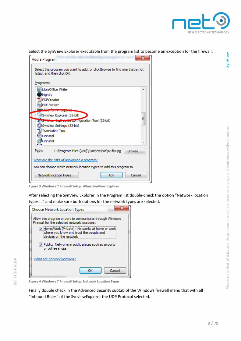
Select the SynView Explorer executable from the program list to become an exception for the firewall:
Figure 3 Windows 7 Firewall Setup: Allow SynView Explorer
After selecting the SynView Explorer in the Program list double-check the option “Network location
types….” and make sure both options for the network types are selected.
Figure 4 Windows 7 Firewall Setup: Network Location Types
Finally double check in the Advanced Security subtab of the Windows firewall menu that with all
“Inbound Rules” of the SynviewExplorer the UDP Protocol selected.

10 / 79
Ple
ase
no
te t
hat
all
dat
a an
d il
lust
rati
on
s ar
e su
bje
ct t
o e
rro
r, c
han
ge a
nd
om
issi
on
s w
ith
ou
t n
oti
ce.
Sy
nV
iew
Rev
. 1.0
2-1
020
14
Figure 5 Windows 7 Firewall: Advanced Security Settings
- If the network configuration, however, requires sharing internet and other network access with the
image acquisition over the same media (which is not recommended practice), the firewall needs to
be configured so that it does not block the communication with the camera. In Windows Firewall
this can be done by creating an exception for each application that will be accessing the camera —
especially for the SynView Explorer that is use for the first tests (possibly limiting the exception's
scope to the local subnet only). Note that the applications to be unblocked (including SynView
Explorer) are not usually present yet in the system at the time of installation. Therefore this step
might have to be repeated after the installation itself and again for each new application. We
recommend to apply a network connection dedicated solely for the camera connection — and
disabling firewall fully for this connection.
CORSIGHT
1. Consult precautions listed in CORSIGHT user manual. Be sure to not violate instructions in the
manual.
2. Unpack the camera, connect necessary peripherals and power it up.
3. Assuming that the desired operating system is already pre-installed on the camera, no additional
steps are needed and the camera is ready for SynView installation and test.
SynView installation — quick guide for Windows
Following points guide quickly through SynView installation under Windows. For detailed instructions or
installation in another operating system, refer to full SynView ”Installation details” p.47.
Installation procedure:
1. Prepare the installation media. The software should be installed by a user with administrator rights.

11 / 79
Ple
ase
no
te t
hat
all
dat
a an
d il
lust
rati
on
s ar
e su
bje
ct t
o e
rro
r, c
han
ge a
nd
om
issi
on
s w
ith
ou
t n
oti
ce.
Sy
nV
iew
Rev
. 1.0
2-1
020
14
a. If the installation CD is at hand, insert it in the CD-ROM drive and wait until installation
starts.
b. If the installer was downloaded from NET´s website, execute it.
2. Depending on security adjustments of the system and whether the installer is running from a local
disk or a network share, a “Open File - Security Warning” might appear. Simply proceed by clicking
"Run". The installer starts with following screen click "Next":
3. Next screen is the license agreement. Please read carefully the license text and, click the "I Agree"
button to proceed with installation:

12 / 79
Ple
ase
no
te t
hat
all
dat
a an
d il
lust
rati
on
s ar
e su
bje
ct t
o e
rro
r, c
han
ge a
nd
om
issi
on
s w
ith
ou
t n
oti
ce.
Sy
nV
iew
Rev
. 1.0
2-1
020
14
4. Next the installer asks about the location where to install SynView. The default location will do well
in most cases. Keep it or select another preferred location and click "Next".
5. If running Windows 7 or a newer Windows version, the default software installation directory
(C:\Program Files) is read only. The installer will ask where to put the application data requiring write
access (the dialog will not appear on Windows XP). Select a desired location and click "Next".
6. In the next step the SynView components must be selected for installation. For testing cameras the
installation of the “runtime” components is sufficient. For programming with SynView he
Developer's tools must be installed as well. When finished with the selection, click "Install".
7. After starting the installation, the selected components will be installed to the computer. The
installer informs about the progress.
8. When completed, the installer displays the final dialog. Keep the default option (Reboot now) and
click "Finish". After rebooting, SynView is ready to use.

13 / 79
Ple
ase
no
te t
hat
all
dat
a an
d il
lust
rati
on
s ar
e su
bje
ct t
o e
rro
r, c
han
ge a
nd
om
issi
on
s w
ith
ou
t n
oti
ce.
Sy
nV
iew
Rev
. 1.0
2-1
020
14
Basic camera configuration
For CORSIGHT cameras no additional actions are needed. Proceed with the testing of the camera. When
using GigEpro/GimaGO easy cameras, the IP configuration must be adjusted for a fit with the network
settings.
Start the SynView GigE Vision Configuration Tool:
Start→Programs→SynView→SynView GigE Vision Configuration Tool (under Linux, start
/opt/synview/bin/sv.ipconf).
The tool will scan for the GigE Vision cameras connected to the system. If the camera(s) is directly
accessible from the PC, they will be displayed with a green “OK” icon. In such case the camera(s) is(are)
ready for acquisition, no further actions are necessary.
If the camera is displayed using a yellow icon, it is “visible” from the PC, but cannot be directly accessed,
because it is configured with a different subnet than the network card. In this case, select the camera in

14 / 79
Ple
ase
no
te t
hat
all
dat
a an
d il
lust
rati
on
s ar
e su
bje
ct t
o e
rro
r, c
han
ge a
nd
om
issi
on
s w
ith
ou
t n
oti
ce.
Sy
nV
iew
Rev
. 1.0
2-1
020
14
the list, adjust its IP configuration, so that it matches settings of the network card, select the Fix IP
checkbox and click the Set persistent Conf button. When finished, the camera's IP configuration should
match the network card. It will display with the green icon in the list and will be now directly accessible
from the PC. It is ready for test.
If desired, the camera's “nickname” (user name) can be adjusted as well, together with the IP
configuration. The nickname can be used to identify individual cameras connected to the network.
Testing camera(s)
The SynView package contains the SynView Explorer tool, which allows to enumerate, connect and
configure cameras, acquire images or generate sample source code for the SynView API. It is a useful
tool for testing both the SynView and camera functionality.
1. Start the tool from system menu:
Start →Programs → SynView →SynView Explorer (under Linux, start
/opt/synview/bin/sv.explorer)
2. Connect the camera for test — select the camera in the list of found cameras and press .
Of course, the camera must be connected and powered.
Figure 6 SynView Explorer GigE Cameras

15 / 79
Ple
ase
no
te t
hat
all
dat
a an
d il
lust
rati
on
s ar
e su
bje
ct t
o e
rro
r, c
han
ge a
nd
om
issi
on
s w
ith
ou
t n
oti
ce.
Sy
nV
iew
Rev
. 1.0
2-1
020
14
3. Configure the camera features as desired. Pay attention especially to features in Image Format
Control and Acquisition Control categories.
Figure 7 SynView Explorer Acquisition
4. When prepared, click — the camera should start acquiring. If not, verify again, if the
camera is properly connected and running, if the system is properly configured (remember the
notes above about firewall, network configuration, etc.) or if the camera was not set to triggered
mode, while no trigger was attached.
Figure 8 SynView Explorer Play

16 / 79
Ple
ase
no
te t
hat
all
dat
a an
d il
lust
rati
on
s ar
e su
bje
ct t
o e
rro
r, c
han
ge a
nd
om
issi
on
s w
ith
ou
t n
oti
ce.
Sy
nV
iew
Rev
. 1.0
2-1
020
14
5. While the acquisition is active, the user can still adjust the runtime parameters, such as exposure
time or gain. Basic acquisition parameters, such as pixel format or trigger mode become locked
when the acquisition starts.
Figure 9 SynView Play and Multiwindow Pre-view
6. When finished, click and exit.
Figure 10 SynView Stop Acquisition

17 / 79
Ple
ase
no
te t
hat
all
dat
a an
d il
lust
rati
on
s ar
e su
bje
ct t
o e
rro
r, c
han
ge a
nd
om
issi
on
s w
ith
ou
t n
oti
ce.
Sy
nV
iew
Rev
. 1.0
2-1
020
14
What next?
After the basic tests and the verification, the user might want to:
- Get more detailed information about installation process for all supported operating systems
Installation details p.47 or information about customizing the Linux installer ”Custom installation”
p.64.
- Learn about SynView configuration options (”SynView Settings utility and configuration file” p.67)
and overview of troubleshooting and technical support approach (”Troubleshooting & Support
p.74).
- Get overview about SynView package, its components, functionality and connectivity (”SynView
overviewSynView overview” p.18), including the SynView Explorer tool (”SynView Explorer in
Detail”p.24). Learn to understand the GenICam based camera feature tree and other important
SynView API principles (”
-
-
-
-
-
-
-
-
- Important principles of the SynView interface” p.39).
- Know basics about the important machine vision standards, GenICam and GigE Vision (”Vision
Standards” p.70) and how to take advantage of advanced support for these standards in SynView
when interfacing 3rd party software and hardware products.
- Study documentation for the hardware:
GigEpro user manual
CORSIGHT user manual
- Study documentation for the SynView API:
SynView programmer's guide

18 / 79
Ple
ase
no
te t
hat
all
dat
a an
d il
lust
rati
on
s ar
e su
bje
ct t
o e
rro
r, c
han
ge a
nd
om
issi
on
s w
ith
ou
t n
oti
ce.
Sy
nV
iew
Rev
. 1.0
2-1
020
14
SynView overview
This chapter gives a high level description of the SynView installer, its components and the supported
hardware.
Connecting an application with NET cameras
The SynView installer is available in versions for Windows and Linux operating systems, running on 32-
bit and 64-bit PC architectures.
All supported platforms are treated with the same priority the since beginning, share the equivalent
feature range and provide the same toolset. Releases for all platforms are synchronized and all tests are
executed on every platform. Migrating to a different operating system or upgrading to a 64-bit
architecture is thus very straightforward and painless.
There are multiple ways how to include our cameras in the application. The most natural one is to use
the SynView software package and its SynView API library, which provides all the means for comfort
work with the hardware and the acquired images. The sample code generator accompanying the library
helps to integrate SynView in the user´s application with very limited effort. Because the low level
hardware access library is a full featured GenICam GenTL Producer, the entire functionality of all NET
camera models is readily available in any image processing software package supporting GenTL standard,
such as Halcon, ActivVisionTools or Common Vision Blox. Furthermore, the GigE Vision based cameras
(GigEpro and GimaGO easy) are fully compatible also with those packages that did not yet implement
GenTL.
Figure 11 SynView connectivity capabilities

19 / 79
Ple
ase
no
te t
hat
all
dat
a an
d il
lust
rati
on
s ar
e su
bje
ct t
o e
rro
r, c
han
ge a
nd
om
issi
on
s w
ith
ou
t n
oti
ce.
Sy
nV
iew
Rev
. 1.0
2-1
020
14
Thanks to SynView's wide compatibility with GenTL and GigE Vision standards, NET can also
accommodate customers who need to combine our cameras with a 3rd party model in a single project
with a single API.
SynView GenTL Producer
The SynView's hardware access layer unifies access to the entire camera product range, covering all
interface and sensor types and exposes that through a single interface. The interface is compatible with
the GenICam GenTL standard (being a full featured GenTL Producer) and can thus be connected to
SynView upper layers (SynView API) or to any GenTL Consumer library. SynView is also a fully GigE
Vision compatible software.
SynView API
The diagram shows the basic architecture of the SynView API library, showing the most commonly used
components.
Figure 12 Main abstractions of the SynView API and their relationships

20 / 79
Ple
ase
no
te t
hat
all
dat
a an
d il
lust
rati
on
s ar
e su
bje
ct t
o e
rro
r, c
han
ge a
nd
om
issi
on
s w
ith
ou
t n
oti
ce.
Sy
nV
iew
Rev
. 1.0
2-1
020
14
The SynView API functionality is available either through a pure C interface, through an object-oriented
C++ interface or as a .Net class library.
It supports various use cases, from trivial applications, where most functionality, including configuration,
threading or display is handled internally by the library to complex scenarios, where user have fine grain
control over everything.
Although the library provides the same functionality as any generic GenICam based package, SynView
API goes way further, providing direct access to all common camera features, shortcuts for easy handling
of complex feature sets. Of course it handles all obvious acquisition related tasks such as buffer queuing,
saving images etc.
SynView API comes also with a preprocessing library that unifies access to preprocessing capabilities of
some cameras and similar functionality in the software. When replacing a simple camera with a model
capable of real-time preprocessing, the same user code will keep working seamless, only the task will get
automatically offloaded from the host processor to the camera.
Last but not least, it also offers GUI components and dialogs for inclusion in user applications – such as
the GenICam feature tree control.
While providing add-on features utilizing work with NET cameras, the SynView core is kept strictly
generic, so that it works well with any GenICam compatible product.
SynView Explorer and SynView Source Code Generator
The SynView Explorer tool is a primary testing and demonstration program built on top of the SynView
API — it provides easy access to the SynView API and camera functionality, available right after the
installation without any programming. Besides that, the SynView Explorer offers additional built-in
features designed to assist the developer to create a SynView API application quickly and easily.
The user interface of the SynView Explorer is discussed in ”SynView Explorer in Detail” p.24. Writing
applications utilizing all advantages of modern cameras, in particular if the application should stay
generic, error resistant and open for cameras of different models (possibly even different technologies or
different vendors) requires good understanding of principles behind the GenICam standard.
To simplify and streamline the development process, NET provides the SynView Source Code Generator
tool.

21 / 79
Ple
ase
no
te t
hat
all
dat
a an
d il
lust
rati
on
s ar
e su
bje
ct t
o e
rro
r, c
han
ge a
nd
om
issi
on
s w
ith
ou
t n
oti
ce.
Sy
nV
iew
Rev
. 1.0
2-1
020
14
Figure 13 SynView Source Code Generator features
- Single-line snippets to full-fledged examples including GUI.
- Templates for typical image acquisition and processing tasks, eg. camera enumeration, buffering
techniques, HW/SW preprocessing etc.
- Browsing the camera's feature tree, generating code to control given feature. Browsing the feature
tree including all standard SFNC features.
- Visual tools for complex camera features (trigger modes, complex digital I/O, LUT's and color
transformations, AOI, etc.).
- Interactive camera configuration snapshot & reuse full camera settings.
- C, C++, C++.Net, C# or VB.Net code. Operating system independent code. Optional GUI elements
based on Qt or Win32 API (eventually Xlib).
- Interactive code generation; cut & paste the code to the application.
- Fully generic, works with any GenICam compatible camera.
- Generating customized code examples through several mouse clicks. The tool runs under Windows
and Linux.

22 / 79
Ple
ase
no
te t
hat
all
dat
a an
d il
lust
rati
on
s ar
e su
bje
ct t
o e
rro
r, c
han
ge a
nd
om
issi
on
s w
ith
ou
t n
oti
ce.
Sy
nV
iew
Rev
. 1.0
2-1
020
14
Figure 14 SynView Source Code Generator configuration
Details about the SynView Source Code Generator with guidelines how to use it to quickly develop an
application with SynView API are provided in SynView programmer's guide.

23 / 79
Ple
ase
no
te t
hat
all
dat
a an
d il
lust
rati
on
s ar
e su
bje
ct t
o e
rro
r, c
han
ge a
nd
om
issi
on
s w
ith
ou
t n
oti
ce.
Sy
nV
iew
Rev
. 1.0
2-1
020
14
Industry standards
SynView by NET uses the GenTL interface as a middle layer of the camera SDK. This allows maximum
flexibility and both-side openness of the library. The industrial standards being used in SynView are listed
below. Table 1 Industrial Standards used in SynView SDK
GenApi API, defines means to describe all camera features, their corresponding control
registers and providing access to those features
GenTL GenTL (Transport Layer), an interface between applications and camera-control
libraries, covering device enumeration, image acquisition and related tasks.
SFNC SFNC (Standard Features Naming Convention), standardizing names (IDs), types and
other aspects for most common features of a machine vision camera
GigE Vision Set of UDP/IP based protocols standardizing access to Gigabit Ethernet based
cameras and devices.
More information about these industrial standards is provided in ”Vision Standards” p.70.
Licensing information
The SynView package and/or the software included in the cameras uses the following 3rd party software
components:
- GenApi reference implementation — distributed under the GenICam license by the GenICam
committee. The copyright is held by the GenICam committee. The package as well as the license is
available from www.genicam.org. The GenICam GenApi reference implementation in turn uses
Apache Xalan-C++ and Xerces-C++ libraries (Apache license, www.apache.org ) and the modified
MathParser library (LGPL license, kirya.narod.ru/mathparser.html).
- zlib compression library: available from www.zlib.net under zlib license.
- The Independent JPEG Group's JPEG software (libjpeg): available from www.ijg.org (Independent
JPEG Group).
- OpenCV: available from opencv.willowgarage.com under BSD license.

24 / 79
Ple
ase
no
te t
hat
all
dat
a an
d il
lust
rati
on
s ar
e su
bje
ct t
o e
rro
r, c
han
ge a
nd
om
issi
on
s w
ith
ou
t n
oti
ce.
Sy
nV
iew
Rev
. 1.0
2-1
020
14
SynView Explorer in Detail
The SynView Explorer is a demonstration and developer tool delivered with SynView. It is written fully
using the SynView API and therefore can serve as demo for both the camera and SynView API
capabilities.
In Windows, the SynView Explorer can be started from the system menu:
Start →Programs → SynView →SynView Explorer.
Figure 15 SynView Explorer running under Windows
In Linux, it can be started for example by executing the sv.explorer command from the shell, the installer
attempts to add SynView executables to the system path. If not, it can still be invoked using full path:
/opt/synview/bin/sv.explorer.
Only screen shots from Windows are shown. In Linux they would be identical (with the difference only in
the display options).
SynView Explorer offers its functionality in a set of menus. Many menu items are duplicated as toolbar
buttons, for convenience. In the screen shots we will show mostly the usage of the toolbar buttons.
SynView Explorer can be run in:
- Single camera (compact) mode, which uses only single application window. In this mode only one
camera can be opened.
- Multiple cameras mode, which uses one window for controls and one window for each connected
camera. In this mode multiple cameras can be connected and concurrently used.

25 / 79
Ple
ase
no
te t
hat
all
dat
a an
d il
lust
rati
on
s ar
e su
bje
ct t
o e
rro
r, c
han
ge a
nd
om
issi
on
s w
ith
ou
t n
oti
ce.
Sy
nV
iew
Rev
. 1.0
2-1
020
14
The mode can be set in the Settings dialog (see “Settings” p.36) and is applied when the Explorer is
started next time.
Figure 16 SynView Explorer running in multiple cameras mode
Connection and disconnection of the camera
The first step after starting the tool is to select and connect a camera. SynView Explorer uses regular
SynView approach to enumerate cameras — depending on the configuration it can offer cameras from a
single or from all GenTL Producer libraries available on the system. By default, it connects to the
SynView GenTL Producer, which handles all NET cameras (GigEpro,GimaGO easy , CORSIGHT) as well as
3rd party GigE Vision compatible cameras.
All the found cameras are displayed in a tree on the "Found Cameras" tab. The tree lists all found
Systems (GenTL producers), under each System it lists all Interfaces, containing at least one active device

26 / 79
Ple
ase
no
te t
hat
all
dat
a an
d il
lust
rati
on
s ar
e su
bje
ct t
o e
rro
r, c
han
ge a
nd
om
issi
on
s w
ith
ou
t n
oti
ce.
Sy
nV
iew
Rev
. 1.0
2-1
020
14
(camera), and under each interface it lists all found Devices. When selecting a device, it can be
connected by clicking on , or simply by double-clicking on the device.
Figure 17 SynView Explorer: Connecting a camera
If the desired camera is not available, check again, if it is properly connected and powered. For GigE
Vision cameras, check also the network configuration and firewall settings. SynView Explorer checks for
the cameras´ existence at startup. The user can also update the camera list during the Explorer run —
use the Update camera list(s) menu item.
Figure 18 SynView Explorer: Updating the camera list
SynView Explorer connects the camera in an exclusive access mode, that means other applications
cannot connect to this camera while it is connected by the SynView Explorer. The user can disconnect
the camera and release it for other applications using . Remember to do so when reaching the
Source code wizard, where the generated application will need to connect to the same camera.
Figure 19 SynView Explorer: Disconnecting the camera
27 / 79
Ple
ase
no
te t
hat
all
dat
a an
d il
lust
rati
on
s ar
e su
bje
ct t
o e
rro
r, c
han
ge a
nd
om
issi
on
s w
ith
ou
t n
oti
ce.
Sy
nV
iew
Rev
. 1.0
2-1
020
14
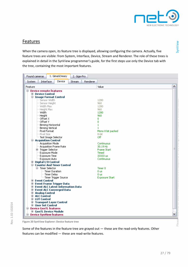
Features
When the camera open, its feature tree is displayed, allowing configuring the camera. Actually, five
feature trees are visible: from System, Interface, Device, Stream and Renderer. The role of these trees is
explained in detail in the SynView programmer's guide, for the first steps use only the Device tab with
the tree, containing the most important features.
Figure 20 SynView Explorer: Device feature tree
Some of the features in the feature tree are grayed out — these are the read-only features. Other
features can be modified — these are read-write features.

28 / 79
Ple
ase
no
te t
hat
all
dat
a an
d il
lust
rati
on
s ar
e su
bje
ct t
o e
rro
r, c
han
ge a
nd
om
issi
on
s w
ith
ou
t n
oti
ce.
Sy
nV
iew
Rev
. 1.0
2-1
020
14
This status need not be permanent, for example some features become read-only during the acquisition
running (like the Width and Height device features). There are features of several types:
- a Boolean value — represented by a check box (for example Chunk Mode Active)
- an integer number — represented by a compound control with edit box, slider, inc/dec buttons (for
example image Width and Height)
- a float number — also represented by a compound control with edit box, slider, inc/dec buttons (for
example Exposure Time)
- an enumeration — represented by a combo box with available choices (for example Pixel Format)
- a string — represented by an edit box (for example Device User ID)
- a command — represented by a button for command execution (for example User Set Load)
Beginner-Expert-Guru level
Features are classified to 3 levels: Beginner, Expert and Guru. While the Beginner level (displayed as
default) contains only a small subset of the most commonly used features, the Guru level hand includes
all available features. In the menu or on the toolbar, the user can switch to the Expert or Guru level,
where a larger subset or all features are displayed.
Figure 21 SynView Explorer: Feature levels
The Guru level provides a multitude of features. We recommend to use the Beginner level features only
for initial experiments and switch to the Expert level, when doing more advanced tests. The Guru level
should be avoided; since features in this level should not be usually touched during regular operation
and altering them can lead to unexpected results.

29 / 79
Ple
ase
no
te t
hat
all
dat
a an
d il
lust
rati
on
s ar
e su
bje
ct t
o e
rro
r, c
han
ge a
nd
om
issi
on
s w
ith
ou
t n
oti
ce.
Sy
nV
iew
Rev
. 1.0
2-1
020
14
Help for a feature
In a set of hundreds of features it may not be easy to guess the purpose of each feature. For this reason,
the device provides also a description of each feature. In the Info panel the Explorer shows the
description for each selected feature:
Figure 22 SynView Explorer Info panel
Device configuration
Typically, the first step is the configuation of the device parameters and then start of the acquisition. In
the tree, any read-write feature can be configured simply by clicking on it — a control window pops up,
enabling to change the feature. Note that the availability of one feature may depend on another —for
example when the Image Width is set to Max Width, then the X Offset is not writable, because the
Width + OffsetX must be less or equal to Max Width, so there is no space to increase the X Offset.
However, when the Width is set smaller, the user will see that the OffsetX becomes writable and that its
maximum value follows the Max Width – Width formula. Furthermore, the availability of the offsets can
be dependent on current ROI Mode.
The tree of camera features follows the principles coming from the GenICam standard. Its subtleties are
discussed in a dedicated “Understanding the feature tree” p.39.Getting familiar with that chapter will
help you to effectively work with the camera.

30 / 79
Ple
ase
no
te t
hat
all
dat
a an
d il
lust
rati
on
s ar
e su
bje
ct t
o e
rro
r, c
han
ge a
nd
om
issi
on
s w
ith
ou
t n
oti
ce.
Sy
nV
iew
Rev
. 1.0
2-1
020
14
Furthermore, the device configuration is also described in detail in the GigEpro Manual and CORSIGHT
manual.
Figure 23 SynView Explorer — Setting a feature (Image Height)
Also note, that some features have so called selectors. For example the device can have several I/O ports
and to configure a specific port, the user should select it by the Line Selector and then the features in the
tree under this selector are used for the selected port.
Figure 24 SynView Explorer — Using a selector (Line)

31 / 79
Ple
ase
no
te t
hat
all
dat
a an
d il
lust
rati
on
s ar
e su
bje
ct t
o e
rro
r, c
han
ge a
nd
om
issi
on
s w
ith
ou
t n
oti
ce.
Sy
nV
iew
Rev
. 1.0
2-1
020
14
How to find a feature
In a complex feature tree it might be difficult to find desired feature. SynView Explorer offers a tool for
finding a feature if a part of its name or display name is enterd.
Figure 25 SynView Explorer Find feature
During typing the feature name SynView Explorer updates a list of all features, in which the written
substring occurs. By clicking on a feature in the list, the feature is focused in the tree.
Figure 26 SynView Explorer — Find feature dialog

32 / 79
Ple
ase
no
te t
hat
all
dat
a an
d il
lust
rati
on
s ar
e su
bje
ct t
o e
rro
r, c
han
ge a
nd
om
issi
on
s w
ith
ou
t n
oti
ce.
Sy
nV
iew
Rev
. 1.0
2-1
020
14
Configuration: Save and Restore
It is possible to store full camera configuration (= all needed features) at any time to a file. That
configuration can be then later reloaded either again in the SynView Explorer or in the user application
(the SynView API provides a function to load settings). Using this functionality, the programmer does not
need to care about the possible feature dependencies, SynView API handles that correctly. Furthermore,
the stored configuration can be used for multiple connected cameras, provided that they are of the same
type and firmware version.
Figure 27 SynView Explorer: Save camera settings
Figure 28 SynView Explorer: Save camera settings dialog

33 / 79
Ple
ase
no
te t
hat
all
dat
a an
d il
lust
rati
on
s ar
e su
bje
ct t
o e
rro
r, c
han
ge a
nd
om
issi
on
s w
ith
ou
t n
oti
ce.
Sy
nV
iew
Rev
. 1.0
2-1
020
14
Acquisition: Start and Stop
After configuration of the camera, the acquisition can be started by using . If the acquisition does
not start as expected, review again the camera feature settings. For GigE Vision cameras, once again, the
network configuration and firewall settings are to be rechecked.
Figure 29 SynView Explorer: Start acquisition
In case the camera is configured for triggered acquisition and the Software Trigger feature becomes
available, the camera can be triggered via in the toolbar:
Figure 30 SynView Explorer: Trigger the camera
Note that some features become read-only with the beginning of the acquisition, for example the image
size can´t be changed during the acquisition. And vice-versa, other features may become usable only
after the beginning of the acquisition — for example the Trigger Software command, if applying the
triggered mode. The acquisition can be stopped through .
Figure 31 SynView Explorer: Stop acquisition

34 / 79
Ple
ase
no
te t
hat
all
dat
a an
d il
lust
rati
on
s ar
e su
bje
ct t
o e
rro
r, c
han
ge a
nd
om
issi
on
s w
ith
ou
t n
oti
ce.
Sy
nV
iew
Rev
. 1.0
2-1
020
14
Display of images
The way how SynView Explorer displays the acquired images can be configured — the available options
are full size (if the image does not fit in the display area, scroll bars are added), scale to fit (image is
scaled to fit to the display area) and tiled display (SynView Explorer displays series of consecutive images
in tiles). Note that the scale to fit and tile modes might not be available in Linux. To be configured
through the Display menu or corresponding buttons.
Figure 32 SynView Explorer: Display modes
Automatic image pre-processing
SynView Explorer makes automatic image pre-processing. This includes the Bayer decoding for color
cameras, applying the LUT (Lookup Table), to which can be added parameters like white balance,
gamma, brightness and contrast, and the color correction, by which can be adjusted the saturation.
SynView automatically determines, if the required functionality is available in camera hardware, and if
not, does the necessary operations by software (this increases the CPU load). The automatic processing
is by default switched on. It can be can switched off in the menu:
Figure 33 SynView Explorer: Automatic image processing
A dialog is displayable, where the processing parameters can be adjusted:
Figure 34 SynView Explorer: Show image processing dialog

35 / 79
Ple
ase
no
te t
hat
all
dat
a an
d il
lust
rati
on
s ar
e su
bje
ct t
o e
rro
r, c
han
ge a
nd
om
issi
on
s w
ith
ou
t n
oti
ce.
Sy
nV
iew
Rev
. 1.0
2-1
020
14
Figure 35 SynView Explorer: Image processing dialog
Note that the white balance factors are always calculated from the next acquired image, so after
pressing "Calculate" button the user will not see a change until a new image is acquired.
Saving acquired image
When the acquisition is stopped, the last acquired image can be saved as a BMP, TIFF or JPEG file. If
automatic processing switched on, the processed image is saved, and otherwise the original image is
saved. Before saving, the image is converted to suitable pixel format, for example when saving an image
with a 12-bit mono pixel format as a BMP or JPEG file it is automatically converted to 8-bit mono pixel
format; in case of a TIFF file it is converted to 16-bit mono pixel format.
Figure 36 SynView Explorer: Save image

36 / 79
Ple
ase
no
te t
hat
all
dat
a an
d il
lust
rati
on
s ar
e su
bje
ct t
o e
rro
r, c
han
ge a
nd
om
issi
on
s w
ith
ou
t n
oti
ce.
Sy
nV
iew
Rev
. 1.0
2-1
020
14
Select the image format in the Save image dialog:
Figure 37 SynView Explorer: Save image dialog
Settings
SynView Explorer settings are available in the menu:
Figure 38 SynView Explorer: Settings

37 / 79
Ple
ase
no
te t
hat
all
dat
a an
d il
lust
rati
on
s ar
e su
bje
ct t
o e
rro
r, c
han
ge a
nd
om
issi
on
s w
ith
ou
t n
oti
ce.
Sy
nV
iew
Rev
. 1.0
2-1
020
14
The following settings are available:
Figure 39 SynView Explorer: Settings dialog
- Start in multiple windows mode (enable usage of multiple cameras). If ON, SynView Explorer starts
in multiple window mode enabling concurrent usage of multiple cameras. If OFF, it starts in a
compact, single window mode, enabling to connect one camera only. This settings applies to the
next SynView Explorer start (does not have an immediate effect).
- Try to connect last used camera at startup. If closing the SynView Explorer without explicitly
disconnecting the camera and this option is ON, the Explorer will attempt to automatically connect
the same camera next time it is run (if the camera is still available).
- Expand the feature trees after connecting the camera. By default the trees are displayed as
collapsed, that means only the top level items are displayed. If this option is set as "ON", all trees are
fully expanded when the camera is connected.
- Switch on all chunk data after connecting the camera. If the camera delivers chunk data with each
image and this option is ON, the Explorer automatically switches on all available chunk data features.
If this option is not used, the selected chunk data features can be switched on manually. Some of the
chunk data are displayed automatically in a line above the image.
Figure 40 Chunk data
- Poll non-cached features in 400 ms interval. If set to ON, the Explorer polls the non-cached features
(such as Device Temperature or Up Time) with the minimum period of 400 ms and updates their
values in the feature tree.

38 / 79
Ple
ase
no
te t
hat
all
dat
a an
d il
lust
rati
on
s ar
e su
bje
ct t
o e
rro
r, c
han
ge a
nd
om
issi
on
s w
ith
ou
t n
oti
ce.
Sy
nV
iew
Rev
. 1.0
2-1
020
14
- Use C escape sequences in strings for non-printable characters. If some of the string features need to
apply a non-printable character (e.g. strings sent via RS-232 port), this option can be switched to ON
for writing and recognizing such characters. Then a C language escape sequence syntax is used for
non-printable characters. The sequence begins with a backslash followed by a single letter (r =
Carriage Return, n = Line Feed, etc.), or a number in form of x + 2 hexadecimal digits or 3 decimal
digits. The number expresses the character ordinal number. A backslash itself must be written as
double backslashes.
\ + letter (b, t, n, v, f, r)
\ + xNN hexadecimal number
\ + NNN decimal number
\\ = \x5C = \092 (backslash)
\b = \x08 = \008 (backspace)
\t = \x09 = \009 (tab)
\n = \x0A = \010 (line feed)
\v = \x0B = \011 (vertical tab)
\f = \x0C = \012 (form feed)
\r = \x0D = \013 (carriage return)
Source code generator
SynView Explorer also provides a powerful set of tools for generating the source code. The detailed
information about the developer assistive tools with guidelines how to use them during development is
provided in the SynView source code generator chapter in the SynView programmer's guide.

39 / 79
Ple
ase
no
te t
hat
all
dat
a an
d il
lust
rati
on
s ar
e su
bje
ct t
o e
rro
r, c
han
ge a
nd
om
issi
on
s w
ith
ou
t n
oti
ce.
Sy
nV
iew
Rev
. 1.0
2-1
020
14
Important principles of the SynView interface
Understanding the feature tree
The “feature tree” is one of the most important patterns used within SynView. It is a tree of
interdependent features used to configure individual hardware and SynView components, with a GenApi
mechanism running under the hood. It is important to understand different aspects of the feature tree
functionality to be able to configure the system effectively and reliably.
Feature tree instances
The feature tree paradigm is reused to configure the devices and various software components. It is
important to understand that the set of supported features can vary significantly among different
hardware (camera) models or even among different revisions of the same model. SynView Explorer
displays all available feature tree instances, allowing configuring the entire system intuitively. The guide
how to control individual features programmatically is provided in SynView programmer's guide.
Remote device features
Set of features used to configure every single device connected to the system. This feature tree is
designed by the device manufacturer (by means of the GenICam standard) and SynView just exposes it
to the user. The “device” is typically a camera, but it can be any configurable device connected to the
system.
GenTL Producer features
Features the configuration of the GenTL Producer, which can be either directly SynView GenTL Producer
or a 3rd party GenTL Producer controlling cameras of another vendor. There is one feature tree available
for each distinct component describing the acquisition system:
- System. Represents a GenTL Producer library. In most cases, there will be just a single system module
available — representing the SynView GenTL Producer.
- Interface. Describes a physical interface used to connect cameras, for example a network segment
interfacing GigE Vision cameras or a bus interfacing the CORSIGHT camera modules.
- Device. Software representation of a device connected to the system.
- Data stream. Controls the stream of the image data coming from the device. In most cases there will
be just a single data stream per device, but there might be devices featuring multiple data streams.
- Buffer. Allows to query information about individual image buffers.
SynView API features
On top of the configuration options provided by the camera itself (and eventually the supporting GenTL
Producer library), SynView API also adds a rich set of features, which are also controlled through a
feature tree. Again, SynView would provide a separate feature tree per component.

40 / 79
Ple
ase
no
te t
hat
all
dat
a an
d il
lust
rati
on
s ar
e su
bje
ct t
o e
rro
r, c
han
ge a
nd
om
issi
on
s w
ith
ou
t n
oti
ce.
Sy
nV
iew
Rev
. 1.0
2-1
020
14
Categories
The features are sorted into categories, grouping together related parameters. The only purpose of
categories is to improve the visual representation of a complex feature tree. From programmer's
perspective (access of individual features), the categories are not important.
Selectors
Selectors are features controlling sets or arrays of identical features.
A selector can be viewed as an analogy of an array index. Similarly as changing an array index does not
by itself modify any value stored in the array, changing a selector does never modify the selected
features — it does not alter the actual camera status.
For example, switching the LineSelector value does not at all change configuration of the I/O lines. It just
selects the line to be configured through the “selected” features, such as LineSource or LineInverter.

41 / 79
Ple
ase
no
te t
hat
all
dat
a an
d il
lust
rati
on
s ar
e su
bje
ct t
o e
rro
r, c
han
ge a
nd
om
issi
on
s w
ith
ou
t n
oti
ce.
Sy
nV
iew
Rev
. 1.0
2-1
020
14
Feature interface types
Depending on the purpose of respective features, they can be represented through different inter faces.
Integer
Up to 64-bit integer value, which can have assigned min/max values and an increment (or a set of
allowed values). The feature values must respect these constraints — if the application tries to set an
invalid value, SynView API readjusts it to the closest valid one.
Float
Floating point number with optional min/max (or set of allowed values). For visualization purposes
(slider in a GUI representation), the floating point features can also have an increment, but unlike with
integers, setting the values aligned with the increment is not forced. The camera can, however, realign
the value internally to a closest valid discrete value — the application can re-read the feature after
setting to know the actually used exact value.

42 / 79
Ple
ase
no
te t
hat
all
dat
a an
d il
lust
rati
on
s ar
e su
bje
ct t
o e
rro
r, c
han
ge a
nd
om
issi
on
s w
ith
ou
t n
oti
ce.
Sy
nV
iew
Rev
. 1.0
2-1
020
14
Enumeration
Feature allowing selecting from given set of entries. Some of the entries might have self-clearing
behavior — they reset automatically to another entry. This behavior is similar to a command feature.
Boolean
Simple flags that can have only two values, true or false.
Command
Purpose of the command features is to init various actions (start acquisition, calibration, automatic white
balance etc.). The command feature provides feedback when the action is finished.
String
String (character) based features.
Register
Memory blob with unspecified representation. Can be used for example to load/save the entire LUT in a
single feature access.
Feature properties
The features have also additional properties, some of them dynamic, which can change during
operation, others static (remain fixed during runtime). SynView API provides access to all these
properties.
43 / 79
Ple
ase
no
te t
hat
all
dat
a an
d il
lust
rati
on
s ar
e su
bje
ct t
o e
rro
r, c
han
ge a
nd
om
issi
on
s w
ith
ou
t n
oti
ce.
Sy
nV
iew
Rev
. 1.0
2-1
020
14
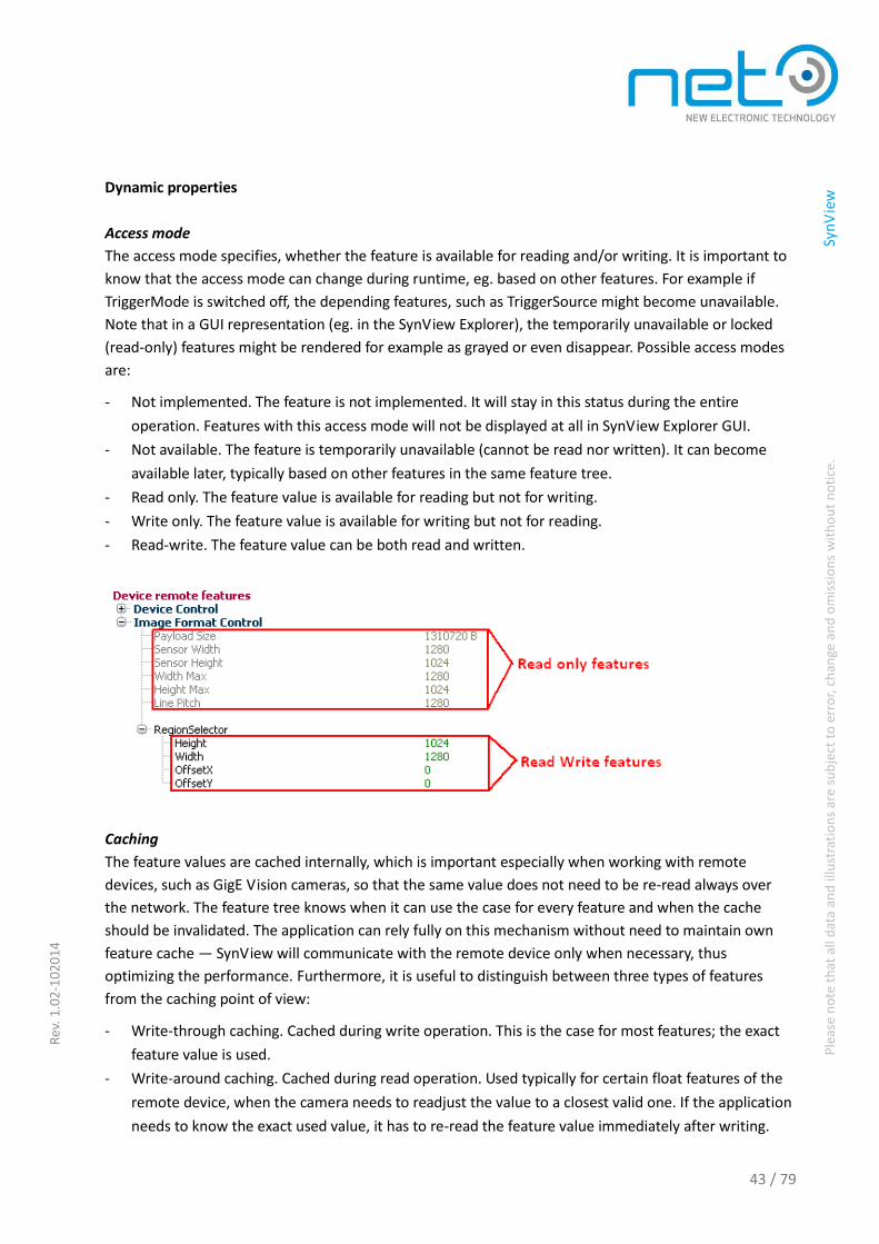
Dynamic properties
Access mode
The access mode specifies, whether the feature is available for reading and/or writing. It is important to
know that the access mode can change during runtime, eg. based on other features. For example if
TriggerMode is switched off, the depending features, such as TriggerSource might become unavailable.
Note that in a GUI representation (eg. in the SynView Explorer), the temporarily unavailable or locked
(read-only) features might be rendered for example as grayed or even disappear. Possible access modes
are:
- Not implemented. The feature is not implemented. It will stay in this status during the entire
operation. Features with this access mode will not be displayed at all in SynView Explorer GUI.
- Not available. The feature is temporarily unavailable (cannot be read nor written). It can become
available later, typically based on other features in the same feature tree.
- Read only. The feature value is available for reading but not for writing.
- Write only. The feature value is available for writing but not for reading.
- Read-write. The feature value can be both read and written.
Caching
The feature values are cached internally, which is important especially when working with remote
devices, such as GigE Vision cameras, so that the same value does not need to be re-read always over
the network. The feature tree knows when it can use the case for every feature and when the cache
should be invalidated. The application can rely fully on this mechanism without need to maintain own
feature cache — SynView will communicate with the remote device only when necessary, thus
optimizing the performance. Furthermore, it is useful to distinguish between three types of features
from the caching point of view:
- Write-through caching. Cached during write operation. This is the case for most features; the exact
feature value is used.
- Write-around caching. Cached during read operation. Used typically for certain float features of the
remote device, when the camera needs to readjust the value to a closest valid one. If the application
needs to know the exact used value, it has to re-read the feature value immediately after writing.

44 / 79
Ple
ase
no
te t
hat
all
dat
a an
d il
lust
rati
on
s ar
e su
bje
ct t
o e
rro
r, c
han
ge a
nd
om
issi
on
s w
ith
ou
t n
oti
ce.
Sy
nV
iew
Rev
. 1.0
2-1
020
14
- No caching. The value is not cached at all. Used for volatile features such as sensor temperature or
similar. The application has to start SynView API polling thread to get the non-cached features
updated regularly. Some features might switch to non-cached mode temporarily, for example the
gain value will become non-cached when automatic gain mode is active.
Limits
Integer and float features have minimum, maximum and an increment (the increment is optional for floats).
The feature value must fall within these limits. Remember that the limits can change during runtime,
depending on other features.
Static properties
Unit
String representation of the physical unit represented by the value.
Display format
Provides hint for graphical representation of the feature value, such as whether the feature has linear or
logarithmic behavior, if it should be displayed in decimal or hex form, etc.
Info texts
Each feature gets a display name (human readable name of the feature), tooltip (short info) and a
description (longer info). These are useful again especially for display and user interaction.

45 / 79
Ple
ase
no
te t
hat
all
dat
a an
d il
lust
rati
on
s ar
e su
bje
ct t
o e
rro
r, c
han
ge a
nd
om
issi
on
s w
ith
ou
t n
oti
ce.
Sy
nV
iew
Rev
. 1.0
2-1
020
14
Feature dependencies
The feature tree knows about possibly complex dependencies between individual features. Changing
value of one feature can affect other feature(s) in following ways:
- Change other feature's value — for a feature which is a direct function of the first one.
- Change other feature's limits — eg. increasing a horizontal offset for the image' area of interest
decreases maximum of the image width.
- Change other feature's access mode — eg. when disabling a trigger, individual trigger parameters
might become unavailable, when starting acquisition, basic acquisition parameters might become
locked.
- Change other feature's effective caching mode — eg. gain value is cached for the “manual” mode,
but non-cached for the “automatic” gain mode.
- Invalidate the other feature — disabling its cache, for example when resetting the camera to a
default status, all feature values must be re-read from the camera rather than from the now-invalid
cache.
To understand the feature tree behavior and treat it properly, it is essential to remember about the
possible feature relationships among certain features. The feature tree handles everything for the user
seamlessly, but note that the feature status can change based on other features and that for some
feature groups the order of writing the features might be significant. To simplify work with such features,
SynView API provides helper functions allowing setting the entire feature group in a single call or even
store/reload entire camera configuration.
Chunk data based features
So called “chunk data” are additional data that a camera can deliver to the buffer together with an
image. These data can contain information such as image timestamp, frame ID or acquisition parameters
used to capture given image. These data can are also part of the feature tree — but they are not read by
querying the camera's current status, but rather directly from the buffer itself. The feature tree internal
logic knows how to access these additional data in the buffer. SynView API provides functions allowing
specifying the “active” buffer that should be connected to the feature tree.
Event based features
Besides the image and chunk data, the remote device (camera) can also fire asynchronous events. These
are useful for variety of purposes, including reporting of asynchronous error and status info, sending log
messages and more. The event itself usually caries also additional data describing the event. These data
are, yet again, integrated into the feature tree. SynView API provides notifications about each received
event, so that the application can track them and possibly query the data associated with every event.

46 / 79
Ple
ase
no
te t
hat
all
dat
a an
d il
lust
rati
on
s ar
e su
bje
ct t
o e
rro
r, c
han
ge a
nd
om
issi
on
s w
ith
ou
t n
oti
ce.
Sy
nV
iew
Rev
. 1.0
2-1
020
14
Feature update notifications in general
The application can instruct the SynView API to provide notification whenever the status of a given
feature changes. The notification would be delivered when feature value has changed, as well as for
other status updates (new access mode, feature cache invalidated, etc.).

47 / 79
Ple
ase
no
te t
hat
all
dat
a an
d il
lust
rati
on
s ar
e su
bje
ct t
o e
rro
r, c
han
ge a
nd
om
issi
on
s w
ith
ou
t n
oti
ce.
Sy
nV
iew
Rev
. 1.0
2-1
020
14
Installation details
This chapter provides detailed overview of SynView installation process for all supported operating
systems. For an express Windows based installation (when details are not important for the user), please
jump to “Quick start” p.7.
Before installation
It is important to know, that the system might not be immediately ready to use after the installation. The
hardware (cameras) might need some basic configuration, as well as the system itself — eg. when using
the GigEpro cameras, the network and firewall must be properly configured. The details are always listed
in the hardware manual of each respective hardware type. The basics are summarized in Section
“Connection and configuration of the camera(s)“ p.7.
Installation in Windows
System requirements
The SynView for Windows does not have any particular system requirements; the installer will install all
the necessary dependencies, including the .NET Framework runtime. SynView is compatible with all
“recent” Windows versions, including Windows 7 or Windows XP. Note that Windows versions older
than Windows XP are not supported.
Note: The SynView package installation should be performed by a user with administrator rights.
Media
The SynView package can be installed from two types of installation media:
- Installation CD-ROM: insert it to the CD-ROM drive. The installation will start automatically.
- Installation CD-ROM is not available or installation of a newer SynView version: download the
installer from the download area on NET´s website: http://www.net-gmbh.com/en/download/
The installer file name follows pattern SynViewxyyzzz.exe, where xyyzzz stands for SynView version.
Execute the installer. Depending on security adjustments of the user´s system and whether the user runs
the installer from a local disk or a network share, the following security warning might appear. Proceed
by clicking "Yes". 1

48 / 79
Ple
ase
no
te t
hat
all
dat
a an
d il
lust
rati
on
s ar
e su
bje
ct t
o e
rro
r, c
han
ge a
nd
om
issi
on
s w
ith
ou
t n
oti
ce.
Sy
nV
iew
Rev
. 1.0
2-1
020
14
Figure 41 SynView installation: Windows security warning
Procedure
The paragraphs below discuss all the dialogs of SynView's Windows installer and corresponding options.
Note that some details might slightly differ between individual SynView versions, but the principles will
always be the same. The installer first displays a welcome screen with basic information about the
software. Click "Next" to proceed.
Figure 42 SynView installation: welcome screen

49 / 79
Ple
ase
no
te t
hat
all
dat
a an
d il
lust
rati
on
s ar
e su
bje
ct t
o e
rro
r, c
han
ge a
nd
om
issi
on
s w
ith
ou
t n
oti
ce.
Sy
nV
iew
Rev
. 1.0
2-1
020
14
Please read carefully the license text and click the "I Agree" button to proceed with installation for
confirmation . Then the user´s full agreement with the license text is assumed.
Figure 43 SynView installation: license agreement
Next the installer asks about the location where to install SynView. The default location C:\Program
Files\SynView should do well in most cases. If another directory is prefered, select it now. When
finished, click the "Next" button.

50 / 79
Ple
ase
no
te t
hat
all
dat
a an
d il
lust
rati
on
s ar
e su
bje
ct t
o e
rro
r, c
han
ge a
nd
om
issi
on
s w
ith
ou
t n
oti
ce.
Sy
nV
iew
Rev
. 1.0
2-1
020
14
Figure 44 SynView installation: destination directory
If running Windows 7 or newer Windows version, the default software installation directory (C:\Program
Files) is read only for regular applications. SynView, however, requires write access for certain files
during operation (“Layout“ p.54). Therefore the installer asks where to put the application data requiring
write access.
Note that in Windows versions older than Windows Vista (in particular in Windows XP) the C:\Program
Files area is not protected and therefore all data can go to a single directory. Also, when installing to a
non-standard location (outside C:\Program Files), the installer assumes the user chooses a writable area
and installs everything to that directory. The dialog will be omitted in these cases.
Choose from these options:
- C:\Users\Public\SynView: recommended when SynView will be used by multiple users.
- C:\Users\YourUserName\AppData\Local\SynView: recommended when SynView will be used by a
single user.
User configured directory — if none of the options above fit the user´s requirements, another directory
can be specify. Be sure the directory has write access to all applications and is not protected by UAC.

51 / 79
Ple
ase
no
te t
hat
all
dat
a an
d il
lust
rati
on
s ar
e su
bje
ct t
o e
rro
r, c
han
ge a
nd
om
issi
on
s w
ith
ou
t n
oti
ce.
Sy
nV
iew
Rev
. 1.0
2-1
020
14
Select the preferred option and click "Next":
Figure 45 SynView installation: application data directory
In the next step select the SynView components to install. The set of actual options can slightly differ
among individual SynView versions. The basic options are:
- Runtime files — files necessary to run every SynView application, these are always installed.
- Development files — essential files for compiling against SynView API as well as additional helper
files. Files in this category are typically installed only on a development system, but not deployed
with final runtime systems.
Include and library files — required for building SynView API applications.
Sample code
- Documentation — full documentation set for SynView package and all NET camera families.

52 / 79
Ple
ase
no
te t
hat
all
dat
a an
d il
lust
rati
on
s ar
e su
bje
ct t
o e
rro
r, c
han
ge a
nd
om
issi
on
s w
ith
ou
t n
oti
ce.
Sy
nV
iew
Rev
. 1.0
2-1
020
14
Note that for testing the cameras, the “runtime” components suffice. However, for programming with
SynView make sure the Developer's tools are installed as well. When finished with the selection, click
"Install":
Figure 46 SynView installation: selecting components
After starting the installation, the selected components will be installed to the user´s computer. The
installer will inform about the progress. Note: the installation includes Microsoft runtime libraries
(Microsoft Visual C++ 2005 Redistributable) which sometimes take longer to be installed.
Figure 47 SynView Installation Progress
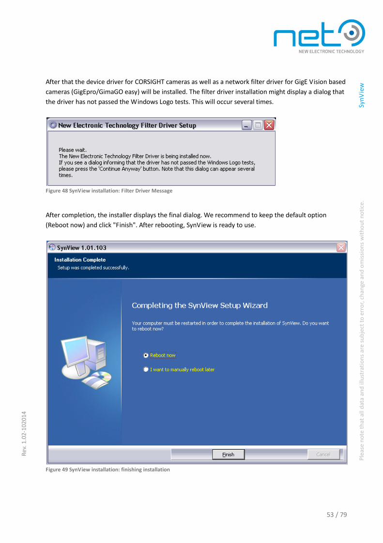
53 / 79
Ple
ase
no
te t
hat
all
dat
a an
d il
lust
rati
on
s ar
e su
bje
ct t
o e
rro
r, c
han
ge a
nd
om
issi
on
s w
ith
ou
t n
oti
ce.
Sy
nV
iew
Rev
. 1.0
2-1
020
14
After that the device driver for CORSIGHT cameras as well as a network filter driver for GigE Vision based
cameras (GigEpro/GimaGO easy) will be installed. The filter driver installation might display a dialog that
the driver has not passed the Windows Logo tests. This will occur several times.
Figure 48 SynView installation: Filter Driver Message
After completion, the installer displays the final dialog. We recommend to keep the default option
(Reboot now) and click "Finish". After rebooting, SynView is ready to use.
Figure 49 SynView installation: finishing installation

54 / 79
Ple
ase
no
te t
hat
all
dat
a an
d il
lust
rati
on
s ar
e su
bje
ct t
o e
rro
r, c
han
ge a
nd
om
issi
on
s w
ith
ou
t n
oti
ce.
Sy
nV
iew
Rev
. 1.0
2-1
020
14
Layout
As mentioned above, the SynView files are installed to two destinations, the main directory and the
application data directory. For the older Windows versions (Windows XP), these two are merged and the
application data directory is actually equivalent to the bin subdirectory of the main installation
destination.
Main installation directory
The main installation directory contains the following subdirectories:
- backup — backup of user modified files (such as the configuration files) that might be overwritten
when upgrading to newer SynView version
- bin — all executable (*.exe) and library (*.dll files belonging to SynView
- data — tool-specific data, eg. templates used by the SynView Source Code Generator
- doc — documentation files
- drivers — drivers (CORSIGHT device driver, network filter driver)
- include — header files for SynView API development
- lib — library (*.lib) files for SynView API development
- samples — additional sample code (most of the samples can be, however, generated interactively
using the SynView Source Code Generator)
Application data directory
The application data directory contains following main components:
- sv.synview.ini — SynView configurations file.
- sv.synview.log — SynView log file.
- XML — contains static XML files copied during installation. None of the files in this directory should
be removed unless being explicitly advised by our support team.
- XMLCache — contains GenICam XML files downloaded from cameras.
- Cache — preprocessed versions of the GenICam XML files for performance improvement. These can
be safely removed SynView will re-generate them upon next use.
- Debug — the .pdb files with debugging information for the SynView libraries. These might be useful
for troubleshooting when contacting our support team.
Network filter driver under Windows
The SynView setup program can install the network filter driver automatically, if desired. The decision
can be made on the setup program's dialog window, where installation components are selected. If not
installed automatically, it is still possible to install the filter driver manually later, as described below.
Before installing it, the user might want to learn more information about the filter driver. In older
SynView versions the setup did not install the filter driver automatically and the user was required to
install it manually.

55 / 79
Ple
ase
no
te t
hat
all
dat
a an
d il
lust
rati
on
s ar
e su
bje
ct t
o e
rro
r, c
han
ge a
nd
om
issi
on
s w
ith
ou
t n
oti
ce.
Sy
nV
iew
Rev
. 1.0
2-1
020
14
Manual filter driver installation
The instructions below describe how to install the network filter driver manually, if not enabled during
installation of the SynView itself. Note that the instructions below assume that SynView is already
successfully installed in the system.
Open the Network Connections applet in the Control Panel.
Windows 7
— menu Start →Control Panel →Network and sharing center →Manage Network Connection
Windows Vista
— menu Start →Control Panel →Network and internet →Network and sharing center →Manage
Network Connection
Windows XP
— menu Start →Settings →Control Panel →Network Connections
Figure 50 Windows 7, Installing the network filter driver, step 1

56 / 79
Ple
ase
no
te t
hat
all
dat
a an
d il
lust
rati
on
s ar
e su
bje
ct t
o e
rro
r, c
han
ge a
nd
om
issi
on
s w
ith
ou
t n
oti
ce.
Sy
nV
iew
Rev
. 1.0
2-1
020
14
Click with the right mouse button on the network connection, which is used to connect the camera(s),
select "Properties" from the context menu.
Figure 51 Windows 7, Installing the network filter driver, step 2
In the "Properties" dialog box select "Install" button to start the installation.
Figure 52 Windows 7, Installing the network filter driver, step 3

57 / 79
Ple
ase
no
te t
hat
all
dat
a an
d il
lust
rati
on
s ar
e su
bje
ct t
o e
rro
r, c
han
ge a
nd
om
issi
on
s w
ith
ou
t n
oti
ce.
Sy
nV
iew
Rev
. 1.0
2-1
020
14
The "Select Network Component Type" dialog box appears. Select "Service" as the new network
component type and click "Add".
Figure 53 Windows 7, Installing the network filter driver, step 4
In the "Select Network Service" dialog box ignore the options possibly offered by the system and click
“Have Disk...” to specify the driver location.
Figure 54 Windows 7, Installing network filter driver, step 5

58 / 79
Ple
ase
no
te t
hat
all
dat
a an
d il
lust
rati
on
s ar
e su
bje
ct t
o e
rro
r, c
han
ge a
nd
om
issi
on
s w
ith
ou
t n
oti
ce.
Sy
nV
iew
Rev
. 1.0
2-1
020
14
In the next dialog browse to the location, where the filter driver files are stored. The directory is
SYNVIEWHOME\drivers\Windows32 , where SYNVIEWHOME is the SynView installation directory
C:\Program Files\SynView by default. When located, click "Next".
For 64-bit Windows the driver files are located in SYNVIEWHOME\drivers\Windows64.
The driver consists of 4 files that should in any case be available to the system in the same directory (that
need to be located in the dialog as described above).
The files are: LvGevDrv.sys (the driver executable itself), the LvGevDrv.inf (the file used to install/uninstall
the driver), the LvGevDrv_m.inf (auxiliary) and the LvDrv.cat with a digital signature.
Windows should successfully find the proper driver and offer it for installation as “New Electronic
Technology SynView Filter Driver”. Select that option and click "OK". Depending on SynView and
Windows versions used one or more dialogs might appear to inform that the driver is not tested for
Windows compatibility. In such case, just click through them, allowing to finish the installation
successfully. When finished the filter driver will be successfully installed and ready to use. It is then listed
in the Local Area Connection properties dialog box.
Figure 55 Windows XP: Filter Driver listed as network service

59 / 79
Ple
ase
no
te t
hat
all
dat
a an
d il
lust
rati
on
s ar
e su
bje
ct t
o e
rro
r, c
han
ge a
nd
om
issi
on
s w
ith
ou
t n
oti
ce.
Sy
nV
iew
Rev
. 1.0
2-1
020
14
Installation in Linux
This section discusses SynView package installation under Linux with notes specific for the most popular
distributions and overview of system requirements.
Installation package types
In Linux there is no single standard way for software installation. The SynView Linux package is therefore
distributed in multiple forms to suit all systems.
RPM format
- Used on most commercial distributions and their community variants, including Fedora/Red Hat,
OpenSUSE/SUSE.
- The package file name is synview-x.yy.zzz.rpm, where x.yy.zzz stands for SynView version.
- To install, execute rpm -i synview-x.yy.zzz.rpm with superuser privileges.
- To uninstall, execute rpm -e SynView with superuser privileges.
DEB format
- Used on Debian based distributions, including Debian, Ubuntu (and variants) or Mint.
- The package file name is synview-x.yy.zzz.deb, where x.yy.zzz stands for SynView version.
- To install, execute dpkg -i synview-x.yy.zzz.deb with superuser privileges.
- To uninstall, execute dpkg -r SynView with superuser privileges.
Compressed archive (TARGZ)
- The .tar.gz archive is intended for systems, where the rpm/deb formats cannot be used or when a
customized installation is required for serious reasons. Details are provided in a separate section
“Custom installation in Linux” p.64.
System requirements
Following list enumerates the most important requirements for installing and using SynView. Note that
the list might not be complete and is subject to change between SynView versions.
- Kernel version: kernels of the 2.6 line. The oldest tested version to date is 2.6.18, SynView is kept
aligned with all the newest kernel version.
- Compiler: g++/gcc 4.1 and newer, libstdc++ v. 6 (GLIBCXX 3.4.5), pthreads implementation NPTL.

60 / 79
Ple
ase
no
te t
hat
all
dat
a an
d il
lust
rati
on
s ar
e su
bje
ct t
o e
rro
r, c
han
ge a
nd
om
issi
on
s w
ith
ou
t n
oti
ce.
Sy
nV
iew
Rev
. 1.0
2-1
020
14
When installing on CORSIGHT, the kernel driver needs to get compiled and configured, therefore the
basic infrastructure for kernel development needs to be available, in particular the basic compiling
tools (gcc and make) and kernel headers. The name of the package containing the kernel headers
might differ among individual distributions (eg. linux-headers, kernel-devel or similar). Additional
system requirements might apply for CORSIGHT systems, if in doubt, contact us to get full list of
distributions supported by the CORSIGHT cameras.
- LSB compatibility and xdg-utils are advantage, but they come by default on most of the usual
distributions.
- To compile samples generated by the SynView Source Code Generator, one needs basic
development tools (make, g++) plus packages for Xlib/Xt development.
Standard installation layout
The SynView installation follows the File system Hierarchy Standard. Its files are distributed in several
directories.
Main installation directory
The main installation directory is /opt/synview.
Figure 56 Linux installation layout, main directory
The main installation directory contains all the runtime binaries and development files. It is organized
in following subdirectories:
- bin — tools and test/demo programs, in particular SynView Explorer (sv.explorer) and SynView
Settings (sv.settings)
- lib — all SynView API libraries, i.e. a directory where the linker should be pointed at; on 64-bit
systems the lib directory contains the 32-bit versions, while the 64-bit ones reside in lib64
- cti — contains the SynView GenTL Producer library; on 64-bit systems the cti directory contains the
32-bit versions, while the 64-bit ones reside in cti64

61 / 79
Ple
ase
no
te t
hat
all
dat
a an
d il
lust
rati
on
s ar
e su
bje
ct t
o e
rro
r, c
han
ge a
nd
om
issi
on
s w
ith
ou
t n
oti
ce.
Sy
nV
iew
Rev
. 1.0
2-1
020
14
- include — SynView API header files
- share — static data files used by SynView
- share/xml — static XML files copied during installation
- req — foreign requisite components used by SynView, in particular the GenICam runtime
- drivers — scripts and sources necessary to build and install SynView device drivers (used only on
CORSIGHT systems)
Configuration files
The configuration files are stored in /etc/opt/synview.
Figure 57 Linux installation layout, configuration file
The directory contains in particular the main SynView configuration file, sv.synview.ini. The file should be
edited with superuser privileges. See Section “SynView Settings utility and configuration file” p.67 for
details.
Application data
The various application data, such as logs and cache go to /var/opt/synview.
Figure 58 Linux installation layout, application data
The data are stored in several subdirectories, in particular:
- log — default destination for SynView log files, in particular the sv.synview.log that are useful for any
troubleshooting (“Troubleshooting & Support p.74).
- XMLCache — contains GenICam XML files downloaded from cameras.

62 / 79
Ple
ase
no
te t
hat
all
dat
a an
d il
lust
rati
on
s ar
e su
bje
ct t
o e
rro
r, c
han
ge a
nd
om
issi
on
s w
ith
ou
t n
oti
ce.
Sy
nV
iew
Rev
. 1.0
2-1
020
14
- GCCache — preprocessed versions of the GenICam XML files for performance improvement. These
can be safely removed. SynView will re-generate them upon next use.
User specific files
Possible user specific files (such as demos'/tools' configuration) are stored in ~/.synview.
Figure 5.18. Linux installation layout, user specific data
This directory is used solely to store user specific settings or preferences for SynView tools, such as
SynView Explorer or SynView Settings. It will not be needed for usual operation on a runtime system.
Other actions performed by the installer
Besides copying the files and adjusting user rights, the installer performs some additional actions,
including:
- When installing on a CORSIGHT system (detected automatically), the necessary device driver is built
and installed.
- For convenience, the directory /opt/synview/bin is added to PATH environment variable, so that the
tools are directly accessible from the shell. This is performed by adding an entry to /etc/profile.d —
on systems using other mechanism, the system administrator might need to adjust the path
manually.
- Directory /opt/synview/cti is added to the GENICAM_GENTL32_PATH environment variable (and
analogically the 64-bit variant), so that the SynView GenTL Producer can be located by 3rd party
GenTL consumers. This is performed by adding an entry to /etc/profile.d — on systems using other
mechanism, the system administrator might need to adjust the path manually.
- For convenience, the directory /opt/synview/lib (and its 64-bit variant) is added to the search path of
the dynamic linker. This is performed by adding an entry to ld.so.conf.d — on systems using other
mechanism, the system administrator might need to adjust the path manually.

63 / 79
Ple
ase
no
te t
hat
all
dat
a an
d il
lust
rati
on
s ar
e su
bje
ct t
o e
rro
r, c
han
ge a
nd
om
issi
on
s w
ith
ou
t n
oti
ce.
Sy
nV
iew
Rev
. 1.0
2-1
020
14
Notes for the most common distributions
The SynView package is tested with the most popular distributions. Brief notes for those distributions
are listed below. Note that this list by no means suggests that other distributions are not supported,
SynView should work on any system fulfilling the basic requirements (“System requirements” p.59). Also
the versions listed for each distribution are just a hint, showing which was the original version used for
tests. Each newer version of given distribution should work well and older versions would work if
fulfilling the mentioned system requirements.
For each distribution, the tests were done with the most basic “default” setup including X, but without
any special additions.
The notes below are related only to SynView itself, assuming the Linux operating system was properly
installed and configured. Special requirements related to operating system installation might apply on
CORSIGHT systems. To install SynView on CORSIGHT, kernel development infrastructure (gcc, make,
kernel headers) must be installed to successfully build and configure the device driver.
Ubuntu
Originally tested version: 10.04 LTS (Lucid Lynx)
Packaging type: deb format
Works out of the box
Debian
Originally tested version: 6.0 (Squeeze)
Packaging type: deb format
Works out of the box
OpenSUSE (community version of SUSE Linux Enterprise)
Originally tested version: 11.2
Packaging type: rpm format
Default installation switches on a paranoid firewall, which has to be configured (or switched off) if
working with GigE Vision cameras (GigEpro/GimaGO easy)
Fedora (community version of Red Hat Enterprise Linux)
Originally tested version: 14 (Laughlin)
Packaging type: rpm format
Default installation switches on a paranoid firewall, which has to be configured (or switched off) if
working with GigE Vision cameras (GigEpro/GimaGO easy)

64 / 79
Ple
ase
no
te t
hat
all
dat
a an
d il
lust
rati
on
s ar
e su
bje
ct t
o e
rro
r, c
han
ge a
nd
om
issi
on
s w
ith
ou
t n
oti
ce.
Sy
nV
iew
Rev
. 1.0
2-1
020
14
Custom installation
Custom installation in Linux
In some situations, the official SynView installers (RPM or DEB) cannot be used, either because given
system does not properly support either of them or when installing to other than default locations is
required for serious reasons. To cover those situations, the SynView package can be on request delivered
in the .tar.gz format. This allows full flexibility during the software installation; however, certain rules
need to be followed to make the installation fully functional. Note that the installation details are subject
to change — in case of doubts or experiencing problems with the installation, contact our support team.
It is highly recommended to use the standard installers wherever possible.
Before planning the installation, please note the section describing the regular installation, including the
system requirements and the default installation layout: Section “

65 / 79
Ple
ase
no
te t
hat
all
dat
a an
d il
lust
rati
on
s ar
e su
bje
ct t
o e
rro
r, c
han
ge a
nd
om
issi
on
s w
ith
ou
t n
oti
ce.
Sy
nV
iew
Rev
. 1.0
2-1
020
14
Installation in Linux” p.59.
Extracting the archive
The package file name is synview-x.yy.zzz.tar.gz, where x.yy.zzz stands for SynView version. As a first step,
the files from the archive should be extracted to the system:
- The opt directory should be extracted to /opt. Alternatively it can be extracted to a custom location,
provided that the environment is properly adjusted, see below.
- The etc directory should be extracted to /etc. Alternatively, it can be extracted to a custom location,
provided that the environment is properly adjusted, see below.
- The var directory (if present in the archive) should be extracted to /var. Alternatively, it can be
extracted to a custom location, provided that the environment is properly adjusted, see below. If the
directory is not present in the archive, we recommend creating it in the target system, including
(empty) subdirectories log, XMLCache and GCCache.
Adjusting the environment
The path to the SynView GenTL Producer needs to be adjusted according to the GenTL standard
requirements:
- On 32-bit installations, the variable GENICAM_GENTL32_PATH must point to the cti subdirectory of
the main SynView installation.
- On 64-bit installations, the variable GENICAM_GENTL64_PATH must point to the cti64 subdirectory
of the main SynView installation.
On systems supporting the /etc/profile.d mechanism, this will be handled automatically by the file
etc/profile.d/synview.sh in the .tar.gz archive. The file, however, assumes default installation locations —
in case of custom installation, its contents need to be adjusted accordingly.
The PATH variable could be adjusted to include the bin subdirectory of the main SynView installation
directory, so that the individual SynView applications can be loaded from the console without specifying
the full path.
Dynamic linking
If desired, the directory with the SynView shared libraries should be added to the search path of the
dynamic linker. The shared libraries are located in lib or lib64 (depending on architecture) subdirectory of
the main SynView installation.
On systems supporting the /etc/ld.so.conf.d mechanism, this will be handled automatically by the file
etc/ld.so.conf.d/synview.conf in the .tar.gz archive. The file, however, assumes default installation
locations — in case of custom installation, its contents need to be adjusted accordingly. To apply the
configuration, the ldconfig command will have to be executed.
The dependencies of the individual SynView libraries and executables should be resolved automatically
— the corresponding links are stored in given files using the DT_RPATH/DT_RUNPATH ELF tags. The tags

66 / 79
Ple
ase
no
te t
hat
all
dat
a an
d il
lust
rati
on
s ar
e su
bje
ct t
o e
rro
r, c
han
ge a
nd
om
issi
on
s w
ith
ou
t n
oti
ce.
Sy
nV
iew
Rev
. 1.0
2-1
020
14
contain both the absolute path (pointing to the default installation locations) and the relative path (using
the “$ORIGIN” convention). This means that dependencies should be automatically resolved even when
installing to a custom location.
Note that in certain situations (such as when using suid binaries), the $ORIGIN based path might be
ignored by the dynamic linker. In such situation, the runpaths need to be adjusted to match the
installation, alternatively another equivalent mechanism (such as LD_LIBRARY_PATH) of choice can be
used.
Access rights
The execution rights for all the executables should be adjusted according to the user´s system policy. The
default installers enable the execution rights for all users. The setuid bit for the sv.fwupgrade can be
added so that the tool is allowed to automatically shutdown the CORSIGHT system after firmware update
The /var/opt/synview directory (or its equivalent specified through LVS_VAR environment variable) and
its subdirectories must have write access for all users.
All other installed files should have at least read access for all users enabled.
Kernel drivers
Depending on the hardware in use, the user might need to install, build and configure the kernel
driver(s) delivered with SynView. This applies in particular to the CORSIGHT device driver (not needed
when using only GigEpro cameras), but in future SynView versions other drivers might be available.
The driver(s) are available in the driver subdirectory of the main SynView installation. There's one
subdirectory per driver. Each driver comes with a control script (typically named control_driver). This
script is used by the default installers to build, install and configure the driver. The script is easy to follow
and commented, so it should be easy for the system administrator to understand its purpose and
eventually adapt the script to match the desired target system. Note that the script is subject to change
any time between SynView versions without prior notice.
Optional files
Some of the files distributed with the SynView package might not be necessary for the basic runtime
operation.
- The tools installed in the bin subdirectory are very useful in the development phase, but might not
be necessary in the target runtime installation. In such case they can be freely omitted without any
harm.
- The 3rd party prerequisite libraries, which are not typically installed on every system, or might be
present in different version, are distributed together with SynView in the req subdirectory. This
covers especially GenApi, Qt, Xerces/Xalan. On embedded, space-sensitive installations, where the
system already contains one or more of these components, the “original” copies can be used instead
of those delivered in the SynView package. It is, however, fully responsibility of the system
administrator to determine and use the proper versions of these prerequisites for every given
SynView version and configure the dynamic linking properly. This is done at the user´s own risk.

67 / 79
Ple
ase
no
te t
hat
all
dat
a an
d il
lust
rati
on
s ar
e su
bje
ct t
o e
rro
r, c
han
ge a
nd
om
issi
on
s w
ith
ou
t n
oti
ce.
Sy
nV
iew
Rev
. 1.0
2-1
020
14
- The support files for the SynView Source Code Generator (in share/srcgen) can be omitted if
SynView Source Code Generator functionality is not needed.
- The contents of the driver’s directory might or might not be needed, depending on the hardware in
use. It is fully responsibility of the system administrator to install and configure all the required
drivers.
- The configuration files from the etc tree can be omitted if the user compensates their purpose by
other means (most of them were discussed above). The only exception is the sv.synview.ini file,
which must always be present.
De-installation/upgrade
When uninstalling or upgrading the SynView package, all relevant steps corresponding with the custom
installation scenario should be performed to keep the system consistent.

68 / 79
Ple
ase
no
te t
hat
all
dat
a an
d il
lust
rati
on
s ar
e su
bje
ct t
o e
rro
r, c
han
ge a
nd
om
issi
on
s w
ith
ou
t n
oti
ce.
Sy
nV
iew
Rev
. 1.0
2-1
020
14
Configuration
SynView Settings utility and configuration file
The SynView configuration options are concentrated in a single file, sv.synview.ini. On Windows systems
the file is located in the “application data” part of the installation. On Linux systems it's stored by default
in /etc/opt/synview.
The file can be edited directly — every single option is well documented directly in the file, including its
possible values. Note that on Linux superuser privileges are required to edit the file.
Instead of editing the file directly, however, the recommended alternative is to edit the file through a
helper utility, SynView Settings (Windows: menu Start →Programs→SynView→Tools→SynView Settings;
Linux: /opt/synview/bin/sv.settings as superuser). The tool provides a comfortable way to edit the
sv.synview.ini file.

69 / 79
Ple
ase
no
te t
hat
all
dat
a an
d il
lust
rati
on
s ar
e su
bje
ct t
o e
rro
r, c
han
ge a
nd
om
issi
on
s w
ith
ou
t n
oti
ce.
Sy
nV
iew
Rev
. 1.0
2-1
020
14
Figure 59 SynView Settings utility
The tool's interface can be controlled through a handful of menu options (or corresponding buttons).
Optionally: show/hide the info pane with info about "The selected configuration" option. Users can

70 / 79
Ple
ase
no
te t
hat
all
dat
a an
d il
lust
rati
on
s ar
e su
bje
ct t
o e
rro
r, c
han
ge a
nd
om
issi
on
s w
ith
ou
t n
oti
ce.
Sy
nV
iew
Rev
. 1.0
2-1
020
14
switch between three configuration levels (beginner, expert, guru) — the higher level, the more detailed
options are shown. Finally, changes can be stored.
The set of options itself is ever evolving, so the SynView Settings tool itself (or the sv.synview.ini file) is
the most complete documentation. The options include detailed logging configuration (see also
Troubleshooting & Support p.74), system installation related info and configuration of individual
SynView subsystems.
Selected configuration options
The documentation for all the SynView configuration options is provided directly in the SynView Settings
utility and the configuration file. A few selected important options as follows:
Logging options
The SynView log is an important tool for any support and troubleshooting. For regular operation, the log
might be kept at low level (default is level Info (4)) or even switched off to optimize the performance.
However, during application development or when debugging a problem, we recommend to switch the
Log level configuration option to Trace (6). All log files sent to our support team should be created with
level Trace (6).
The logging infrastructure is optimized for high performance. For example, the logging to file is buffered
to minimize the disk access overhead. This can have a drawback, however, that in case of an application
crash, the last part of the log might be missing in the file. When troubleshooting application crashes, we
recommend switching on the option Disable all buffering.
Heartbeat timeout
Heartbeat timeout is an important parameter, related to GigE Vision cameras only (GigEpro/GimaGO
easy). This timeout, in milliseconds, defines how frequently the application software has to send the
“heartbeat” messages to the camera, indicating that it is still working and connected to the application.
When the camera does not receive the message within the specified timeout period, it assumes the
application has failed and disconnects itself. The default value used in SynView is 3 s. At most times, the
heartbeat handling is fully transparent to the user. However, during debugging, when a developer stops
the application at a breakpoint for single stepping, the SynView heartbeat handling thread would also
stop, fail to deliver the heartbeat messages and the camera would disconnect. To prevent that, we
recommend increasing the heartbeat timeout parameter to a higher value. Please keep in mind that with
a high heartbeat value the camera will be available later for reconnection in case of an unexpected
disconnect from the application side. The parameter is configurable through camera features at runtime.
Its default value can be adjusted through the SynView Settings utility.
71 / 79
Ple
ase
no
te t
hat
all
dat
a an
d il
lust
rati
on
s ar
e su
bje
ct t
o e
rro
r, c
han
ge a
nd
om
issi
on
s w
ith
ou
t n
oti
ce.
Sy
nV
iew
Rev
. 1.0
2-1
020
14
Vision Standards
The following paragraphs provide brief information about the most important machine vision standards
built into SynView and the GigEpro/GimaGO easy and CORSIGHT camera families.
GenICam
The main idea of the GenICam standard, published first in 2006 under EMVA (European Machine Vision
Association), is to provide a unified application programming interface (API) to the users of machine
vision cameras. It enables an easy integration of individual components, such as cameras, image
processing libraries, drivers or frame grabbers.
GenICam is independent on the transport layer technology. The GigE Vision standard uses GenICam to
access camera configuration. GenICam is also implemented by manufacturers of cameras based on
"older" interface technologies (Camera Link, USB, IIDC DCAM) and efforts are made to integrate
GenICam back into these standards. More importantly, newly developed machine vision standards are
expected to build upon GenICam and smart camera platforms, such as NET CORSIGHT also heavily rely
on GenICam based interoperability. GenICam is thus supported by virtually all important manufacturers
of machine vision components. GenICam consists of three main modules, GenApi, GenTL, and SFNC.
GenApi
GenApi (GenICam Application Programming Interface) is a basic building block of GenICam. It allows
describing complete camera functionality using an XML file with precisely defined syntax. Individual
camera features are described by their name, type (integer, float, boolean, command, string, etc.),
address, length and other parameters of the register controlling the feature, as well as other details
including complex description of logical and mathematical relationships between individual features. The
XML file is usually stored directly on the camera, which further simplifies the automatic configuration
process. The standard clearly defines the way, how the XML configuration file should be interpreted, so
that the host-side implementation (application itself) and camera can cooperate. GenICam also provides
quality reference implementation in form of a set of C++ libraries with license similar to BSD. All
GenICam software products known to the author are using the reference implementation. GenApi is fully
independent on the transport layer, which only has to supply two functions for reading and writing the
camera registers by means of its corresponding protocol (GVCP in case of GigE Vision). The GenApi
principle is revolutionary among other aspects in the degree of flexibility available for the camera
description. GenApi allows exact camera description, while leaving full freedom for layout and
implementation of individual registers, as well as for defining custom features, not specified by the
standard.

72 / 79
Ple
ase
no
te t
hat
all
dat
a an
d il
lust
rati
on
s ar
e su
bje
ct t
o e
rro
r, c
han
ge a
nd
om
issi
on
s w
ith
ou
t n
oti
ce.
Sy
nV
iew
Rev
. 1.0
2-1
020
14
GenTL
GenTL (Transport Layer) is the newest addition to GenICam. It defines interface for acquisition of image
sequences (or additional non-image data) independently on the transport layer technology and platform
(operating system, programming language, etc.).
GenTL allows to enumerate and identify the devices (cameras) connected to the system, control access
to them from individual applications (“GenTL Consumers”), configure them (by means of GenApi),
configure the pool of buffers used for the acquired data and control the acquisition itself, including
synchronization, buffer locking, control of the input and output buffer queues, reading additional data
bound to individual images, etc.
The basic camera functionality is available through programming interface compatible with the ISO norm
for the C programming language. More advanced GenTL features can be configured by means of a
GenApi interface, similarly as the camera itself. In such case the GenTL Producer implements a virtual
register space, described by a similar XML file, which is used also for description of the cameras.
Thanks to GenTL, the applications can use cameras across the transport layer technologies, without
knowing any low-level details about each respective technology.
SFNC
SFNC (Standard Features Naming Convention) is kind of superstructure on top of GenApi. It defines a
convention for naming features typical for machine vision cameras. SFNC defines a universal camera
model, which might be implemented by most of the cameras on the market. Generic applications and
libraries can, thanks to this standard model, automatically comprehend virtually any newly connected
camera and configure it according it needs, without "manual" intervention from the programmer or user.
SFNCC thus practically takes the full freedom of GenApi and ties it again to a clearly defined model, so
the features listed in the XML configuration file can be automatically (ie. without study of the
documentation) bound to a particular meanings. Nevertheless, the camera implements this model only
to the level possible and practical for its design. The designer has still full freedom for adding his own
extensions and features not defined by the standard.
The SFNC model is very comprehensive, allowing defining most of the camera functionality, perhaps just
with exception of very specific features.
GigE Vision
GigE Vision is relatively young but already very mature and widely adopted standard published in 2006
under AIA (Advanced Imaging Association). It defines interface (set of communication protocols) for
industrial cameras using Ethernet as its transport media. The goal of the standard was to reach high

73 / 79
Ple
ase
no
te t
hat
all
dat
a an
d il
lust
rati
on
s ar
e su
bje
ct t
o e
rro
r, c
han
ge a
nd
om
issi
on
s w
ith
ou
t n
oti
ce.
Sy
nV
iew
Rev
. 1.0
2-1
020
14
degree of interoperability between individual manufacturers. Despite of the name, suggesting that it was
originally designed for gigabit Ethernet, the standard itself does not define any particular transport
media and enables thus transition to faster media (10G Ethernet) in future.
Main advantages of GigE Vision against competing technologies are:
- Gigabit Ethernet infrastructure is readily available in most current systems and is well known.
- Sufficient bandwidth for most of current camera designs.
- Cable length up to 100 meters without regeneration, with switches the length is practically
unlimited.
- Number of cameras available in the system is practically unlimited.
- Wide spectrum of network topologies, support for multicasting etc. enable to build specific systems
with eg. multiple cameras simultaneously available (and simultaneously acquiring) to multiple host
computers.
- Plug&play, support of GenICam standard.
- Cost savings thanks to utilization of cheap, off-the-shelf equipment such as network cards (instead of
specialized frame grabbers), standard network cables, etc. Total costs can compete even with analog
systems.
GigE Vision is actually set of protocols built on top of UDP/IP. UDP was selected to achieve maximum
possible performance. Error checking and repairing mechanisms are available directly by means of the
GigE Vision protocols, if it is required by the application.
Main components of the standard are Device Discovery, GVCP, GVSP, Bootstrap registers:
Device discovery
Device discovery is the mechanism allowing discovery and identification of GigE Vision compatible
cameras available in the system. The application issues (broadcast) a request for identification of the
cameras. Individual cameras must react to this request by sending their card, containing for example the
camera's IP address, name of the camera manufacturer and model name, as well as other basic
information.
The application can change the IP configuration of the camera (e.g. to bring it to its own subnet) and
request exclusive rights to access the camera.
GVCP
Once the connection is established, the application communicates with the camera using GVCP (GigE
Vision Control Protocol). Its task is to control all the communication with the camera, especially read and
write all the camera's control registers and allow thus the actual image acquisition.
GVSP
As soon as the camera is configured through GVCP, it can start sending the image and other data. GigE
Vision defines GVSP (GigE Vision Streaming Protocol) for this purpose. GVSP mainly defines how the
image data are packetized and it also offers means for recovery from possible errors occurring during the
data transfer.

74 / 79
Ple
ase
no
te t
hat
all
dat
a an
d il
lust
rati
on
s ar
e su
bje
ct t
o e
rro
r, c
han
ge a
nd
om
issi
on
s w
ith
ou
t n
oti
ce.
Sy
nV
iew
Rev
. 1.0
2-1
020
14
Bootstrap registers
The most basic camera parameters, allowing its identification and establishing the connection are
summarized in a mandatory block of registers, so called bootstrap registers. The layout of additional
registers defining specific camera functionality is left completely up to the camera implementation. The
camera describes that layout using XML file compatible with the GenICam standard. This configuration
file is usually stored directly on the camera and can be downloaded by means of GVCP.

75 / 79
Ple
ase
no
te t
hat
all
dat
a an
d il
lust
rati
on
s ar
e su
bje
ct t
o e
rro
r, c
han
ge a
nd
om
issi
on
s w
ith
ou
t n
oti
ce.
Sy
nV
iew
Rev
. 1.0
2-1
020
14
Troubleshooting & Support
Getting support for NET products
Before contacting the support team
To get the most effective support, please make sure to check if the issue does not belong to the list of
the most common issues (providing solutions to all of them).
Send the problem report to proper e-mail address, depending on the location and the problem nature,
as explained in Section “Technical Support“ p.78.
Make sure the problem is reproducible, preferably with the SynView Explorer and to capture the
sv.synview.log file (See next chapter: “Gathering information about the problem”).
Attach the captured log file (one per each session if multiple test scenarios are described in the report)
as well as other important information, describe all details about the problem, see “Reporting the
problem“ p.75. Following these guidelines will guarantee that the problem can be solved effectively, in
the shortest possible time.
Gathering information about the problem
When collecting information about a problem, please follow the steps listed hereafter:
- Be sure to use the latest version of SynView. The bug may already be removed in the meantime. The
version of currently installed SynView is visible in the SynView Explorer tool (menu Help →About).
The latest SynView version can be downloaded from the SynView download area.
- Enable logging. Before attempting to reproduce the problem, be sure the logging is enabled through
the SynView Settings tool (or directly the sv.synview.ini file (refer to Section “SynView Settings
utility and configuration file“ p.67) enable logging to file, preferably with highest log level. If the
application crashes and the log is not complete, switch on the "Disable all buffering log
configuration" option.
- Test the hardware functionality with a supplied demo program “SynView Explorer”. As the first step
use the “standard” demo program, SynView Explorer, which covers most of the possibilities of NET
hardware usage. If being able to reproduce the problem in SynView Explorer, then the problem is
probably not in the code. However, it still need not be a bug, a problem can be also caused by an
improper configuration.
- Camera configuration. Check especially whether the camera is set in a proper working mode. See
camera documentation to learn how the camera should be adjusted.
- Check another hardware. Sometimes the problem can be caused by the HW/SW environment or by a
defective piece of hardware. Try if the same problem happens on another PC. Try another camera if
available. For GigE Vision based cameras, review the network configuration and try to connect the
camera directly, without additional network components in the path.

76 / 79
Ple
ase
no
te t
hat
all
dat
a an
d il
lust
rati
on
s ar
e su
bje
ct t
o e
rro
r, c
han
ge a
nd
om
issi
on
s w
ith
ou
t n
oti
ce.
Sy
nV
iew
Rev
. 1.0
2-1
020
14
- Check the application. If the problem could not be reproduced in the previous steps, reproduce the
problem in the application. If possible, extract and send us the smallest part of the code that can
demonstrate where the problem occurs. Prefereably, make the extracted code fragment compilable,
so that the problem can be reproduced with a small application that is send to us. Make sure that
the application does proper error handling when accessing SynView functions. Ignoring the error
status of SynView functions can lead to unexpected behavior of the application.
- Screenshots. In case of disturbances in the acquired images, do and send the screenshots of them,
either as bitmaps with lossless compression (.bmp, .png) or as .jpg with a high quality (small
compression).
- Send us the report. Send all the collected information (and especially the sv.synview.log file) to us,
following guidelines from the next chapter: “Reporting the problem”.
Reporting the problem
Each problem report should contain following information:
- The email subject should give a brief but specific description of the problem and user´s company
name (separated by a “@” character). The subject will be used to identify the evolution of the
support case. If a different problem is reported, a new subject string must be created.
Example of a good subject: Changing exposure time has no effect @ My Company Inc.
Example of a bad subject: Problem with camera
- Describe the problem in detail, including all its symptoms, conditions under which it occurs and all
other information that can help resolving the problem. List all the information gathered while testing
and reproducing the problem, as described in Chapter “Gathering information about the problem“
p.74.
- Attach the required sv.synview.log file (one per each reported session). The file absolutely essential
for NET´s support team and failing to attach it will usually only lead to a response asking to collect
and send it, which will in effect make the time needed for the resolution longer. Be sure to send the
log file generated during the problematic session together with the report.
- For troubleshooting a CORSIGHT camera running Linux, attach also the device driver log (Linux driver
logging“ p.77) and contents of /proc/lvsm. The driver logs are appended to the standard kernel log
and can be retrieved for example using the dmesg command.
- If the problem occurs only under some conditions or only with some particular piece of hardware or
software, describe the differences between the two cases and attach log files generated during both
the successful and problematic sessions. If only a specific sequence of steps leads to the problem,
describe this sequence.
77 / 79
Ple
ase
no
te t
hat
all
dat
a an
d il
lust
rati
on
s ar
e su
bje
ct t
o e
rro
r, c
han
ge a
nd
om
issi
on
s w
ith
ou
t n
oti
ce.
Sy
nV
iew
Rev
. 1.0
2-1
020
14
Troubleshooting of NET products
Troubleshooting common issues
The lists below mention some most common issues that can be faced by customers, but have easy
solution. It is a good idea to check this list first when encountering a problem. It is also a good idea to
check the next Chapter “SynView logging” whether some hints can be found there.
- If the user is not getting any image, or different image data than expected or if there are problems
with acquisition timing, the camera should be checked carefully in regard of the settin of the proper
working mode and that it is not in some error status (see camera manual for possible description of
such situations).
If problems occur with acquisition from a GigEpro/GimaGO easy camera, check whether the firewall
settings do not interfere with the acquisition.
SynView logging
All the SynView components are using a common logging subsystem, which can be configured through
the sv.synview.ini and SynView Settings (“SynView Settings utility and configuration file“ p.67).
The log can be directed to various outputs, while the most important of them (especially for support) is
the file output. The log file path can be adjusted however the default name (sv.synview.log) as well as
the default location (application data directory under Windows, /var/opt/synview/log under Linux) will
be just right in most situations.
The logging level can be adjusted. The default level Info (4) provides most useful information about the
system and SynView operation. For specific troubleshooting and support requests, it is often useful to
switch to the most verbose level Trace (6).
In case of troubleshooting problems involving an application crash, when the log might not be written
completely (log buffers not flushed completely at the time of application crash), the logging subsystem
should be configured to avoid any buffering. In such case, please switch on the Disable all buffering
option.
The logging configuration offers advanced options, the most important of them being the max allowed
size of the log file. The log can be also directed to other outputs, but those are mainly intended for use
during advanced debugging by qualified personnel.
Several logging mechanisms are used by various SynView components. They are separated to utilize log
analysis, to separate domain-specific info from the general purpose logs and to improve performance,
logging only what needs to get logged in a given situation. Creation of these log files can usually be
controlled by the user.
Note: All information in the logs is informative and its main purpose is to assist the NET support team
when trying to resolve possible problems. It is not designed as a tool that should be necessarily well
understandable by users, it might be misleading and all the information is context-specific. If a word
“error” or “warning” appears in the log, it does not necessarily mean a real error occurred, it might be

78 / 79
Ple
ase
no
te t
hat
all
dat
a an
d il
lust
rati
on
s ar
e su
bje
ct t
o e
rro
r, c
han
ge a
nd
om
issi
on
s w
ith
ou
t n
oti
ce.
Sy
nV
iew
Rev
. 1.0
2-1
020
14
valid situation in a given context. Don't get alarmed because of that and contact support, especially if the
application is otherwise working well.
Linux driver logging
On the CORSIGHT systems, a device driver controlling the acquisition device is running. The driver can
also provide useful logs, but those are not routed through SynView user level logging subsystem, but
rather through standard Linux kernel logging mechanisms. Depending on the system configuration, there
might be multiple ways to access that log, but the most convenient is usually to simply execute the
dmesg command and store its output to a file. Apart of the kernel log messages, other (mostly static)
information can be available through reading the /proc/svsm.
Debugging with GigE Vision cameras
When debugging an application using GigE Vision cameras (GigEpro/GimaGO easy), it's necessary to pay
attention to a low level GigE Vision communication parameter, the heartbeat timeout.
This timeout, in milliseconds, defines how frequently has the camera send the “heartbeat” messages to
the camera, indicating that it's still alive. When the camera does not receive the message within the
specified timeout period, it assumes the application has gone away and disconnects itself. The default
value used in SynView is 3 s (other software packages might use another value).
At most times, the heartbeat handling is fully transparent to the user. However, during debugging, when
a developer stops the application at a breakpoint for single stepping, the SynView heartbeat handling
thread would also stop, fail to deliver the heartbeat messages and the camera would disconnect. To
prevent that, we recommend to increase the heartbeat timeout parameter to a higher value. It has to be
understood that when the application stops unexpectedly during debugging the camera would not
disconnect properly and it will take according to the debug heartbeat setting longer time before the
camera becomes available again for connection. The heartbeat parameter is configurable through
camera features at runtime (the feature's GenICam name is GevHeartbeatTimeout), while its default
value can be adjusted through the SynView Settings utility, configuration option Heartbeat timeout.
Note that some software packages attempt to increase the timeout automatically, whenever they find
out that a debugger is attached to the process. We don't do that since we believe that the correct
heartbeat timeout value can only be determined by the application developer, for reasons described
above.
Debugging symbols
When debugging certain kinds of problems, such as application crash, it might be very useful to provide
extended diagnostic information to the support team, such as the stack trace showing the crash point.
The installer of SynView for Windows allows to install “PDB files” — files containing the debugging
information (symbols) for the SynView libraries. We recommend to install these debug files on the
development and testing systems, so that it is possible to generate the stack trace info whenever
encountering a problem. The files are located in the bin\Debug subdirectory of the SynView installation.
Note that in Linux version of SynView the symbols are directly included in the libraries and executables.

79 / 79
Ple
ase
no
te t
hat
all
dat
a an
d il
lust
rati
on
s ar
e su
bje
ct t
o e
rro
r, c
han
ge a
nd
om
issi
on
s w
ith
ou
t n
oti
ce.
Sy
nV
iew
Rev
. 1.0
2-1
020
14
Technical Support
NET ensures the conformity of its product to be reliable and free from defects during manufacturing by
testing all the cameras before release. However, unexpected problems and technical issues may come
up due to the complexity of the product.
For technical support contact the agent near you or contact NET directly at the following locations:
Websites
Europe www.net-gmbh.com
France www.net-france-sas.fr
Italy www.net-italia.it
USA www.net-usa-inc.com
Asia www.net-japan.com
Europe [email protected]
France [email protected]
Italy [email protected]
Asia [email protected]
Phone
Europe +49 8806 92 34-0
France +33 450 452 292
Italy +39 030 5237 163
USA +1 219 934 9042
Asia +81 454 781 020
Fax
Europe +49 8806 92 34-77
Italy +39 030 5033 293
USA +1 219 934 9047
Asia +81 45 476 2423
In case of an RMA, the user must first contact NET and obtain an RMA Number before sending the
product to NET. We are not responsible for any problems caused by not following the RMA procedure.

80 / 79
Ple
ase
no
te t
hat
all
dat
a an
d il
lust
rati
on
s ar
e su
bje
ct t
o e
rro
r, c
han
ge a
nd
om
issi
on
s w
ith
ou
t n
oti
ce.
Sy
nV
iew
Rev
. 1.0
2-1
020
14
IMPRINT
NET New Electronic Technology GmbH
Address:
Lerchenberg 7
D-86923 Finning
Germany
Contact:
Phone: +49-88 06-92 34-0
Fax: +49-88 06-92 34-77
www.net-gmbh.com
E-mail: [email protected]
VAT- ID: DE 811948278
Register Court: Augsburg HRB 18494
Copyright © 2013 NEW ELECTRONIC TECHNOLOGY GMBH
All rights reserved.