Embed Size (px)
Citation preview

Quick Start Guide – Ultra KR5O Data Radio
CONTROLMICROSYSTEMS
IntroductionWelcome to the Quick Start Guide for the Ultra KR50 Data Radio. This guide provides step-by-step instructions, with simple explanations to get you up-and-running.For further information, please refer to the Ultra-Series User Manual.
Typical Radio Setup
Quick Start Guide - Ultra KR50 Data Radio 1
Mounting and Environmental ConsiderationsThe radio should be mounted in a clean and dry location, protected from water, excessive dust, corrosive fumes, extremes of temperature and direct sunlight. In high power or high temperature applications, please allow sufficient passive or active ventilation. To best avoid moisture ingress mount the radio with the connectors facing downwards.
Connecting Antennas and RF FeedersThe RF antenna system should be installed in accordance with the manufacturers notes. Antenna gain must be considered when setting Transmit Power. Refer to Compliance notices at the end of this document.The RF connectors are TNC Type female connectors. Always use good quality low loss feeder cable, selected according to the length of the cable run. Ensure all external connections are waterproofed using amalgamating tape.Preset directional antennas in the required direction using a compass, GPS, or visual alignment and ensure correct polarisation (vertical or horizontal).Note: Use ANT1 for Point to Point systems.
Power Supply RequirementsTx: Nominal 13.8 V @ 500 mA (Max 1A)Rx: Nominal 13.8V @ 120 mASafe Operating Voltage 10- 30 V (24V @ 300 mA)
Power Supply Protection and PrecautionsThe KR50 radio modem will operate from a 10 to 30 volt (filtered) DC supply. The radio is designed to self protect from permanent damage if the voltage exceeds 30V dc or if reverse polarity is applied. The replaceable internal fuse has a rating 3 Amp. Only use lead free solder and soldering equipment to replace the fuse.The current requirement is typically 200mA @ 13.8V in receive mode, and will vary in transmit mode according to RF output power level.
SCADAWave Ultra KR5O Quick Start Guide
2 Quick Start Guide - Ultra KR50 Data Radio Quick Start Guide - Ultra KR50 Data Radio 3
The radio modem can also be damaged if there is any potential difference between the chassis-ground, RS232 signal ground, power (-) input, or antenna coaxial shield.
Before connecting any wiring, ensure all components are earthed to a common ground point (please pay particular attention to 24V PLC power systems where converters are used). Connect the antenna and RS 232 plugs BEFORE applying power to the unit. Lastly, before inserting the power plug, please re-check that the polarity and voltage on the DC power plug is correct using a multimeter.
Communications PortsSystem Port - RJ45The System Port is used for Programming / Configuration of the radio and can be used for Remote Diagnostics connections .To access these functions use the SCADAWave E&K Cable assembly (RJ45 Cable and RJ45to DE-9 Adaptor).You can make your own cable using the pinouts shown below
System Description DE-9F
Pin 1 System Data Out Pin 2
Pin 2 System Data In Pin 3
Pin 3 Reserved N/C
Pin 4 Shutdown N/C
Pin 5 Programming Only Pin 5
Pin 6 Reserved N/C
Pin 7 Ground Pin 5
Pin 8 External PTT N/C

Port A - RJ45 RS232/RS485 Connector
Communications PortsPort A -RJ45User port A is configurable for RS-232 and RS-485 operation with no handshaking, or hardware flow control using RTS & CTS. RS-485 Operation is also possible but requires internal jumper links to be changed - consult the Ultra-Series User Manual for more information on RS-485.In most systems flow control is not required, in which case only 3 wires need to be connected between the radio and the application device. 3 Wire Connection:• Pin5(RxD)-dataoutputfromtheradiomodem,• Pin6(TxD)-datainputtotheradiomodem,• Pin4(SG)-signalground.
SCADAWave Ultra KR5O Quick Start Guide
Communications PortsPort B -RS232User port B is wired as a RS232 DCE, configurable for no handshaking (3-wire interface) , or hardware flow control using RTS, CTS. In most systems flow control is not required, in which case only 3 wires need to be connected between the radio and the application device. 3 Wire Connection:• Pin2(RxD)-dataoutputfromtheradiomodem• Pin3(TxD)-datainputtotheradiomodem• Pin5(SG)-signalgroundRefer to User manual for further details of other cable configurations.
Interface CableInterface Cable
4 Quick Start Guide - Ultra KR50 Data Radio Quick Start Guide - Ultra KR50 Data Radio 5
Port B - DE-9F

SCADAWave Ultra KR5O Quick Start Guide
6 Quick Start Guide - Ultra KR50 Data Radio Quick Start Guide - Ultra KR50 Data Radio 7
Optimising the Antenna for Rx SignalWhen using a directional antenna, it will be necessary to align the antenna for the best received signal. This can be done using SCADAWave Manager Diagnostics or by measuring the RSSI output on Pin 9 of Port B which indicates signal strength.This voltage can be converted to dBm using the chart below.
SCADAWave ManagerRadio ConfigurationSCADAWave Manager offers a number of features including: Configuration (Local , or Remote - over-the-air), Remote Diagnostics Facilities and Firmware Upgrades.Example: Local configuration session - 1/ Attach the programming cable from a PC RS232 Port to the System Port 2/ Launch SCADAWave Manager & Select “Ultra-Series Programmer” 3/ Select Basic Mode or Advanced Mode 4/ Click on the “Read” icon 5/ Change the configuration as required 6/ Click on “Write” to write the parameters back to the radioRefer to Ultra-Series User Manual for detailed operation of advanced features.
LED Indicators
DC PowerIf all the LEDs are off, no DC power is reaching the radio modem or the internal fuse is open. Successful power-up is indicated by the Pwr/Tx LED showing a continuous GREEN state for Remotes or an alternating Red/Green for Masters.When the transmitter is active the Pwr/Tx LED is in a RED state.Received Signal IndicatorA regular flashing GREEN LED indicates that the modem is synchronised to its Master. The GREEN LED will also flash when the modem is receiving data. A regular flashing RED LED indicates the REMOTE is not synchronised to a MASTER or BRIDGE. Check the antenna, all RF connections, and the radio configuration as the Subnet ID may not match the Master or their may be insufficient RX signal or too much interference.Port A and Port B Data Flow The RxD/TxD LEDs indicate data flow into and out of the two user ports. Data being received at the port for transmission is indicated by a RED flash, and data being received over the air and then sent from the port is shown as a GREEN flash.Error LED IndicationsIn some circumstances the radio will indicate an error state. This is shown as all LEDs flashing RED for 500mS and then a pattern of green LEDs for 500mS. The pattern of green LEDs indicate the type of error:
Pwr/Tx Sync/NoRx Port A Port B Error Type
Green Off Green Off High VSWR - Check antenna and RF connections
Green Green Green Off High Temperature - Cool the radio
Green Green Green Green External Voltage too high or too low - Out of spec
SCADAWave Ultra KR5O Quick Start Guide
8 Quick Start Guide - Ultra KR50 Data Radio Quick Start Guide - Ultra KR50 Data Radio 9
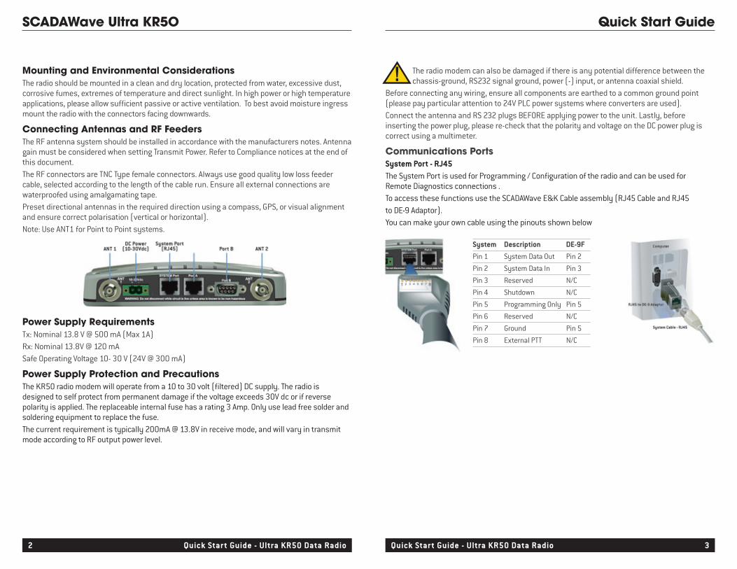
Step 1 - RF and DC power connectionRF ConnectionIt is recommended that whip antennas are used to simulate a long distance RF link. RF attenuators are far superior to antennas for short-distance bench testing as the attenuation of the RF signals between both radios is consistent and is not subject to external interference. Alternatively 90dB of separation can be achieved with 50 ohm dummy loads or small whip antennas (minimum separation 5m/20ft).1/ If the TX power of each radio is set to 20dBm (100mW) then low power, low cost attenuators can be used.2/ Small whip antennas should only be used if the test area is known to be free from interference and signal into the receiving radio are no greater than -30dBm and Tx power is set to 10dBm.DC Power Connection Ensure each radio is wired using the correct polarity and that power supply for has adequate current delivering capacity.
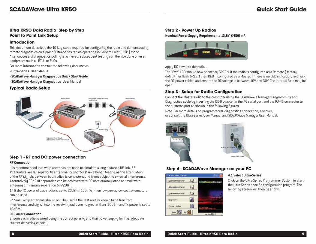
Step 2 - Power Up RadiosNominal Power Supply Requirements 13.8V @500 mA
Apply DC power to the radios.The “Pwr” LED should now be steady GREEN if the radio is configured as a Remote ( factory default ) or flash GREEN then RED if configured as a Master. If there is no LED indication, re-check the DC power cables and ensure the DC voltage is between 10V and 30V. The internal fuse may be open.
Step 3 - Setup for Radio ConfigurationConnect the Master radio to the computer using the SCADAWave Manager Programming and Diagnostics cable by inserting the DE-9 adapter in the PC serial port and the RJ-45 connector to the systems port as shown in the following figures.Note: For more details on programmer & diagnostics connection, see over, or consult the Ultra-Series User Manual and SCADAWave Manager User Manual.
Step 4 - SCADAWave Manager on your PC4.1 Select Ultra-SeriesClick on the Ultra-Series Programmer Button to start the Ultra-Series specific configuration program. The following screen will then be shown.
Ultra KR5O Data Radio Step by StepPoint to Point Link Setup
IntroductionThis document describes the 10 key steps required for configuring the radio and demonstrating remote diagnostics on a pair of Ultra-Series radios operating in Point to Point ( PTP ) mode. After successful diagnostics polling is achieved, subsequent testing can then be done on user equipment such as RTUs or PLCs.For more information consult the following documents:- Ultra-Series User Manual- SCADAWave Manager Diagnostics Quick Start Guide- SCADAWave Manager Diagnostics User Manual
Typical Radio Setup
8.1 Create DatabaseCreate a New database using the menu option File -> Newor Open an existing database using menu option File->Open.If a new database, the Individual Unit Database Setup window will open
SCADAWave Ultra KR5O Quick Start Guide
10 Quick Start Guide - Ultra KR50 Data Radio Quick Start Guide - Ultra KR50 Data Radio 11
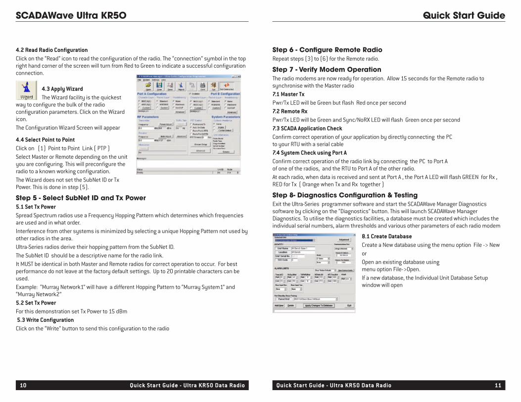
4.4 Select Point to PointClick on (1) Point to Point Link ( PTP )Select Master or Remote depending on the unit you are configuring. This will preconfigure the radio to a known working configuration. The Wizard does not set the SubNet ID or Tx Power. This is done in step (5).
Step 5 - Select SubNet ID and Tx Power5.1 Set Tx PowerSpread Spectrum radios use a Frequency Hopping Pattern which determines which frequencies are used and in what order.Interference from other systems is minimized by selecting a unique Hopping Pattern not used by other radios in the area.Ultra-Series radios derive their hopping pattern from the SubNet ID.The SubNet ID should be a descriptive name for the radio link.It MUST be identical in both Master and Remote radios for correct operation to occur. For best performance do not leave at the factory default settings. Up to 20 printable characters can be used.Example: “Murray Network1” will have a different Hopping Pattern to “Murray System1” and “Murray Network2”5.2 Set Tx PowerFor this demonstration set Tx Power to 15 dBm 5.3 Write ConfigurationClick on the “Write” button to send this configuration to the radio
4.2 Read Radio ConfigurationClick on the “Read” icon to read the configuration of the radio. The “connection” symbol in the top right hand corner of the screen will turn from Red to Green to indicate a successful configuration connection.
4.3 Apply Wizard The Wizard facility is the quickest
way to configure the bulk of the radio configuration parameters. Click on the Wizard icon.The Configuration Wizard Screen will appear
Step 6 - Configure Remote RadioRepeat steps (3) to (6) for the Remote radio.
Step 7 - Verify Modem OperationThe radio modems are now ready for operation. Allow 15 seconds for the Remote radio to synchronise with the Master radio7.1 Master Tx Pwr/Tx LED will be Green but flash Red once per second 7.2 Remote RxPwr/Tx LED will be Green and Sync/NoRX LED will flash Green once per second7.3 SCADA Application CheckConfirm correct operation of your application by directly connecting the PC to your RTU with a serial cable7.4 System Check using Port AConfirm correct operation of the radio link by connecting the PC to Port A of one of the radios, and the RTU to Port A of the other radio.At each radio, when data is received and sent at Port A , the Port A LED will flash GREEN for Rx , RED for Tx ( Orange when Tx and Rx together )
Step 8- Diagnostics Configuration & TestingExit the Ultra-Series programmer software and start the SCADAWave Manager Diagnostics software by clicking on the “Diagnostics” button. This will launch SCADAWave Manager Diagnostics. To utilise the diagnostics facilities, a database must be created which includes the individual serial numbers, alarm thresholds and various other parameters of each radio modem
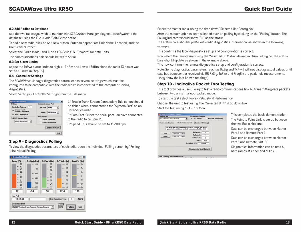
Step 9 - Diagnostics PollingTo view the diagnostics parameters of each radio, open the Individual Polling screen by “Polling ->Individual Polling.
Select the Master radio using the drop down “Selected Unit” entry box. After the master unit has been selected, turn on polling by clicking on the “Polling” button. The Polling indicator should show “ON” as the status. The status bars should update with radio diagnostics information as shown in the following example .This confirms the local diagnostics setup and configuration is correct.Now select the remote unit using the “Selected Unit” drop down box. Turn polling on. The status bars should update as shown in the example above. This now confirms the remote diagnostics setup and configuration is correct. Note: Some diagnostics parameters (such as RxSig and TxPwr) will not display actual values until data has been sent or received via RF. RxSig, TxPwr and FreqErr are peak-held measurements (they show the last known readings).
Step 10 - Indicative Packet Error TestingThis tool provides a useful way to test a radio communications link by transmitting data packets between two units in a loop-backed mode. To start the test select Tools -> Statistical Performance.Choose the unit to test using the “Selected Unit” drop down boxStart the test using “START” button
This completes the basic demonstrationThe Point to Point Link is set up between the two Radio Modems.Data can be exchanged between Master Port A and Remote Port A.Data can be exchanged between Master Port B and Remote Port B.Diagnostics Information can be read by both radios at either end of link.
SCADAWave Ultra KR5O Quick Start Guide
12 Quick Start Guide - Ultra KR50 Data Radio Quick Start Guide - Ultra KR50 Data Radio 13
8.2 Add Radios to DatabaseAdd the two radios you wish to monitor with SCADAWave Manager diagnostics software to the database using the File -> Add/Edit/Delete option.To add a new radio, click on Add New button. Enter an appropriate Unit Name, Location, and the Unit Serial Number.Select the Radio Model and Type as “K-Series” & “Remote” for both units.The communications port should be set to Serial. 8.3 Set Alarm LimitsAdjust the TxPwr alarm limits to High = 17dBm and Low = 13dBm since the radio TX power was set to 15 dBm in Step (5).8.4 - Controller SettingsThe SCADAWave Manager diagnostics controller has several settings which must be configured to be compatible with the radio which is connected to the computer running diagnostics.Select Settings > Controller Settings from the File menu
1/ Enable Trunk Stream Connection: This option should be ticked when connected to the “System Port” on an Ultra-Series radio.2/ Com Port: Select the serial port you have connected to the radio to on your PC. 3/ Speed: This should be set to 19200 bps.
FCC Part 15 Notice This device complies with Part 15 of the FCC Rules. Operation is subject to the following two conditions: (1) this device may not cause harmful interference, and (2) this device must accept any interference received including interference that may cause undesired operation.FCC Approved Antennas This device can only be used with Antennas listed in the Appendix of the Ultra-Series User Manual. Please Contact Control Microsystems if you need more information or would like to order an antenna.RF ExposureTo satisfy FCC RF exposure requirements for mobile transmitting devices, a separation distance of 23 cm or more should be maintained between the antenna of this device and persons during device operation. To ensure compliance, operations at closer than this distance is not recommended. The antenna used for this transmitter must not be co-located in conjunction with any other antenna or transmitter.MAXIMUM EIRPFCC Regulations allow up to 36 dBm effective isotropic radiated power (EIRP). Therefore, the sum of the transmitted power (in dBm), the cabling loss and the antenna gain (in dBi) cannot exceed 36 dBm.AUSTRALIAN COMPLIANCE NOTICE: MAXIMUM EIRPACMA Regulations allow up to 30 dBm (1 Watt) of effective isotropic radiated power (EIRP) in the 915MHz license free band and 36 dBm (4 Watts) of EIRP in the 2.4GHz band. Therefore, the sum of the transmitted power (in dBm), the cabling loss and the antenna gain cannot exceed the above stated EIRP limits.
Contactwww.controlmicrosystems.comThe Control Microsystems web site has links to e-mail and telephone support, technical notes, manuals, and software updates.
FCC Compliance Notices
Applies to models KR900-xxxxx-xHx(CSA Marked)This product is available for use in Class I, Division 2, Groups A, B, C & D Hazardous Locations. Such locations are defined in Article 500 of the US National Fire Protection Association (NFPA) publication NFPA 70, otherwise known as the National Electrical Code and in Section 18 of the Canadian Standards Association C22.1 (Canadian Electrical Code).The transceiver has been recognised for use in these hazardous locations by the Canadian Standards Association (CSA) International. CSA certification is in accordance with CSA Standard C22.2 No. 213-M1987 and UL Standard 1604 subject to the following conditions of approval:1. The radio modem must be mounted in a suitable enclosure so that a tool is required to gain access for disconnection of antenna, power and communication cables.2. The antenna, DC power and interface cables must be routed through conduit in accordance with the National Electrical Codes.3. Installation, operation and maintenance of the radio modem should be in accordance with the radio modem’s user manual and the National Electrical Codes.4. Tampering or replacement with non-factory components may adversely affect the safe use of the radio modem in hazardous locations and may void the approval.5. A power connector with locking screws as supplied by Control Microsystems MUST be used.
WARNING EXPLOSION HAZARD
Important Notices for Class 1, Division 2Groups A, B, C & D Hazardous Locations
SCADAWave Ultra KR5O Quick Start Guide
14 Quick Start Guide - Ultra KR50 Data Radio Quick Start Guide - Ultra KR50 Data Radio 15

16 Quick Start Guide - Ultra KR50 Data Radio
SCADAWave Ultra KR5O Quick Start Guide
CONTROLMICROSYSTEMSw w w. c o n t r o l m i c r o s y s te m s . c om
O ttawa n Calgar y n Denver n Hous ton n Melbourne n LeidenW ithin Nor th A merica: (888) 267-2232 n Outside Nor th A merica: (613) 591-1943Control Microsystems reserves the right to change product specifications without notice. Printed in Canada n V003 n 250229