Embed Size (px)
Citation preview
Quick Start GuideRelion® 611 series
1 Display Use navigation buttons for entering to submenus
2 Self-supervision and
protection indicator LEDs
Ready-LED steady: OK, Ready-LED flashing: Internal Relay Fault (IRF), Start-LED steady: protection started,
Start-LED flashing: protection function blocked, Trip-LED: protection operated
3 Programmable LEDs Can be programmed for alarming and indication with latching and/or flashing features
4 Control Circuit Breaker (CB) Press open/close and confirm by pressing enter. Note: control has to be in Local mode.
5 Escape / Cancel Used for canceling actions and leaving setting mode without saving the values. Returns back to menu.
6 Navigation Left = go back, Right = go further, Up = scroll up, Down = scroll down. Are also used for changing setting
values.
7 Enter / Select Entering to parameter setting mode and confirming new values
8 Local / Remote Changes the control between Local/Remote
9 Help View help menu
10 Front communication port RJ-45 port can be used for connecting the IED to a PC
1
2 3
5
8 9
104
7
6

2 Quick start guide | Relion® 611 series
Using the local HMI
Accessing main menu and changing parametersPress to navigate to the main menu from the measurements view.
From the main menu, go to Settings and press . Then press or to select the setting value you want to change. Press to change it with or buttons. If there is a “#” mark on the same line as the parameter value, you have to first select which setting group parameter you want to change. If there is no “#” mark then you can change the value directly by pressing and then with or or
or buttons.
You can change all parameters in the same way. The most common function block names are described at the end of this document.
Storing settingsParameters have to be stored before taken into use. Store the settings by going back to the main menu by pressing the button. The IED will ask for confirmation to commit changes, answer “Yes“. Some changes require the IED to reboot before the changes are taken into use. Reboot the IED by going to main menu Configuration → General → Software reset or by switching the auxiliary power off and back on.
Changing the overcurrent start valueFrom the main menu, go to Settings → Settings → select setting group, default 1 and press
→ Current Protection → PHLPTOC1 → Start value.
Changing function block naming from IEC 61850 names to IEC 60617 From the main menu, go to Configuration → HMI → FB Naming convention.
Checking binary input valueFrom the main menu, go to Monitoring → I/O Status → Binary input values → select correct BIO card.
Checking fault records and measurement values of the latest faultsFrom the main menu, go to Monitoring → Recorded data → Fault record.
Clearing events, indications and programmable LEDsFrom the main menu, go to Clear. Select the item you want to clear and press and select Clear by pressing (Cancel will disappear). Confirm by pressing .
Checking IED order code, serial number, HW revision and software versionFrom the main menu, go to Information → Product Identifiers.
Display header areaThe icon area at the upper right corner of the dislay shows the current action or user level. These are described below:
S = Parameters are being stored ! = Warning and/or indication V = Viewer O = Operator E = Engineer A = Administrator
Checking the input and output status of a function blockFrom the main menu, go to Monitoring → I/O status.
Checking the IP addressThe address of the front communication port is fixed: 192.168.0.254. If the IED is equipped with a communication card you can check the IP address of the rear communication port from the main menu Configuration → Communication → Ethernet → Rear port(s).
Activating the Web HMI To activate the Web HMI from the main menu go to Configuration → HMI → Web HMI mode. Activation requires rebooting the IED.
Changing the display contrastHold and press or to change the display contrast. The display contrast setting is automatically stored when A (Administrator) is visible in the icon area at the upper right corner of the display.

Relion® 611 series | Quick start guide 3
Using the Web HMI
Connect PC to the IED front communication port with a Ethernet cable. Enter the IP address 192.168.0.254 in a web browser. For full access, login with administrator username and password. The username is "ADMINISTRATOR" and the default password is "remote0004".
Changing the overcurrent start value via WebHMIIt is important to enable writing to the IED. If write is disabled it is not possible to change settings.
Click settings in the left menu bar, then go to Settings → Settings → Current Protection → PHLPTOC1 → Start value.
After you have changed the start value parameter, click "Write to IED" and click "Commit" in the notification bar that opens.
Input and output signal configuration Click the corresponding area to view a specific logical group, and then the switch groups included in the logical group are listed in the Function View page. Click "Overview" to go back to the overview page.
Changing the overcurrent start value via WebHMI
Input and output signal configuration
IMR
S75
7627
B
© C
opyr
ight
201
2 A
BB
. A
ll rig
hts
rese
rved
.
For more information please contact:
ABB Oy Medium Voltage Products Distribution AutomationP.O. Box 699 FI-65101 Vaasa, Finland Phone: +358 10 22 11 Fax: +358 10 22 41094
www.abb.com/substationautomation
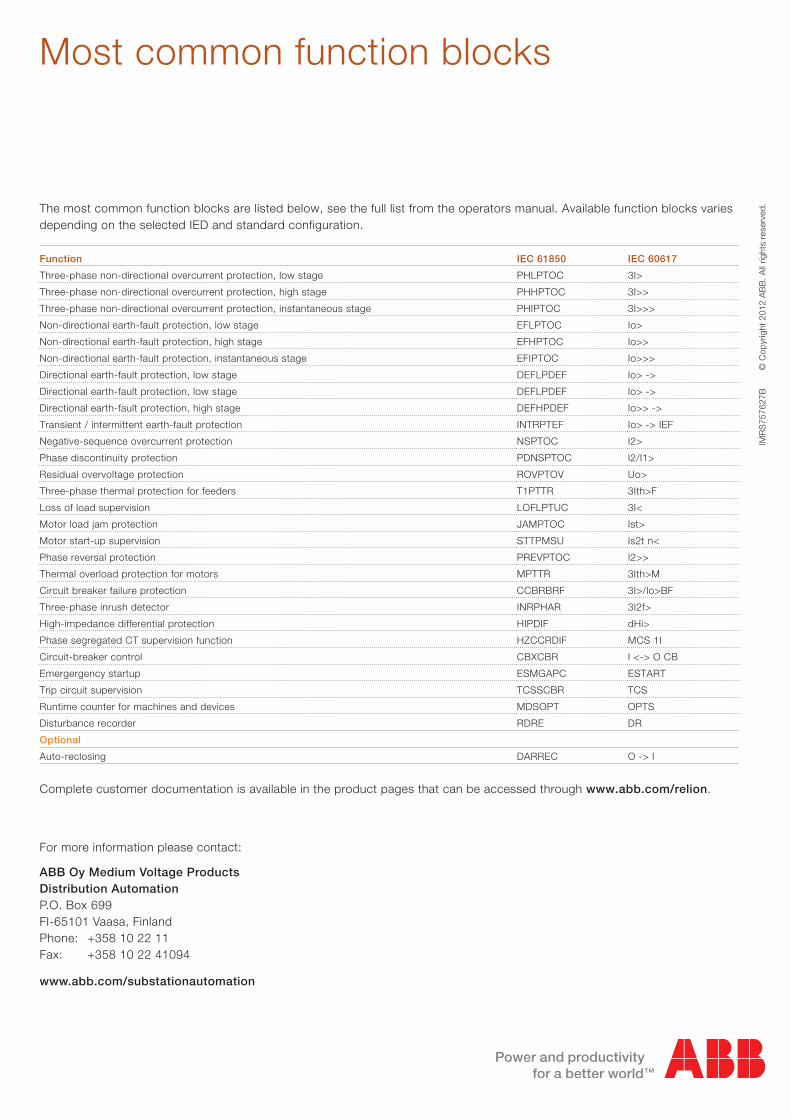
Function IEC 61850 IEC 60617
Three-phase non-directional overcurrent protection, low stage PHLPTOC 3I>
Three-phase non-directional overcurrent protection, high stage PHHPTOC 3I>>
Three-phase non-directional overcurrent protection, instantaneous stage PHIPTOC 3I>>>
Non-directional earth-fault protection, low stage EFLPTOC Io>
Non-directional earth-fault protection, high stage EFHPTOC Io>>
Non-directional earth-fault protection, instantaneous stage EFIPTOC Io>>>
Directional earth-fault protection, low stage DEFLPDEF Io> ->
Directional earth-fault protection, low stage DEFLPDEF Io> ->
Directional earth-fault protection, high stage DEFHPDEF Io>> ->
Transient / intermittent earth-fault protection INTRPTEF Io> -> IEF
Negative-sequence overcurrent protection NSPTOC I2>
Phase discontinuity protection PDNSPTOC I2/I1>
Residual overvoltage protection ROVPTOV Uo>
Three-phase thermal protection for feeders T1PTTR 3Ith>F
Loss of load supervision LOFLPTUC 3I<
Motor load jam protection JAMPTOC Ist>
Motor start-up supervision STTPMSU Is2t n<
Phase reversal protection PREVPTOC I2>>
Thermal overload protection for motors MPTTR 3Ith>M
Circuit breaker failure protection CCBRBRF 3I>/Io>BF
Three-phase inrush detector INRPHAR 3I2f>
High-impedance differential protection HIPDIF dHi>
Phase segregated CT supervision function HZCCRDIF MCS 1I
Circuit-breaker control CBXCBR I <-> O CB
Emergergency startup ESMGAPC ESTART
Trip circuit supervision TCSSCBR TCS
Runtime counter for machines and devices MDSOPT OPTS
Disturbance recorder RDRE DR
Optional
Auto-reclosing DARREC O -> I
Most common function blocks
Complete customer documentation is available in the product pages that can be accessed through www.abb.com/relion.
The most common function blocks are listed below, see the full list from the operators manual. Available function blocks varies depending on the selected IED and standard configuration.