Embed Size (px)
Citation preview

PM172 Quick Start Guide
Series PM172 Powermeters 1
1
Quick Start Guide
PM172 Series Powermeters PM172P/PM172E/PM172EH

PM172 Quick Start Guide
2 Series PM172 Powermeters
2
Introduction The PM172 is a compact, multi-function, three-phase AC powermeter and power quality analyzer specially designed to meet the requirements of users ranging from electrical panel builders to substation operators.
If you are familiar with the PM172 Powermeter, use this quick start guide to prepare the units for operation. If you are not familiar with the PM172, read the Installation and Operation Manual carefully before installing and using the unit.
This quick start guide does not contain information on all the features of PM172. See the Installation and Operation Manual for full operating details and features.
Assembly Instructions
Figure 1: Instrument Dimensions
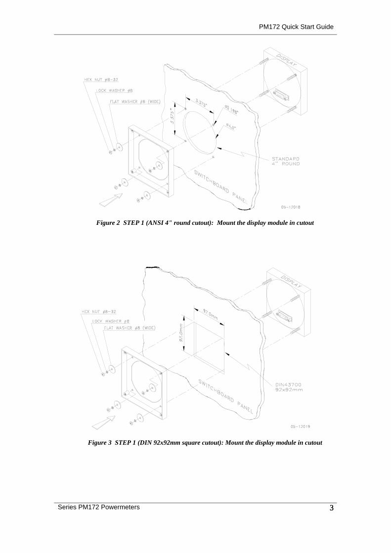
The PM172 is mounted in a standard 4-inch round or DIN92 square cutout.
PM172 Quick Start Guide
Series PM172 Powermeters 3
3
Figure 2 STEP 1 (ANSI 4" round cutout): Mount the display module in cutout
Figure 3 STEP 1 (DIN 92x92mm square cutout): Mount the display module in cutout
PM172 Quick Start Guide
4 Series PM172 Powermeters
4
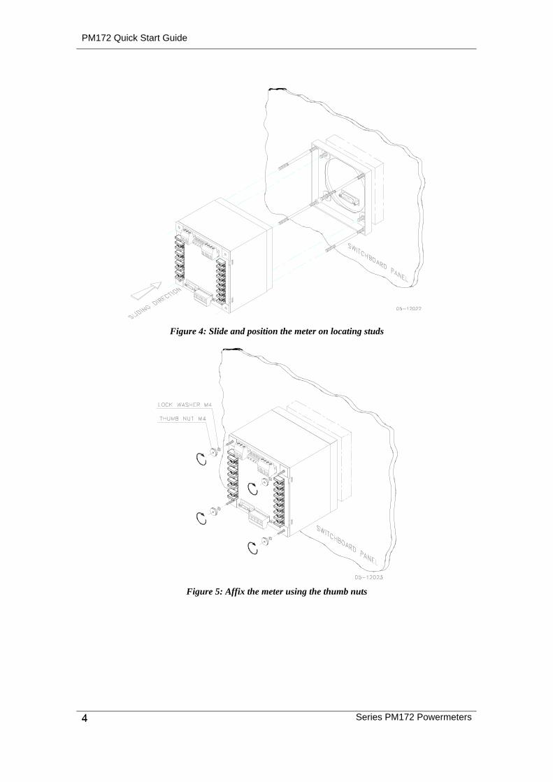
Figure 4: Slide and position the meter on locating studs
Figure 5: Affix the meter using the thumb nuts
PM172 Quick Start Guide
Series PM172 Powermeters 5
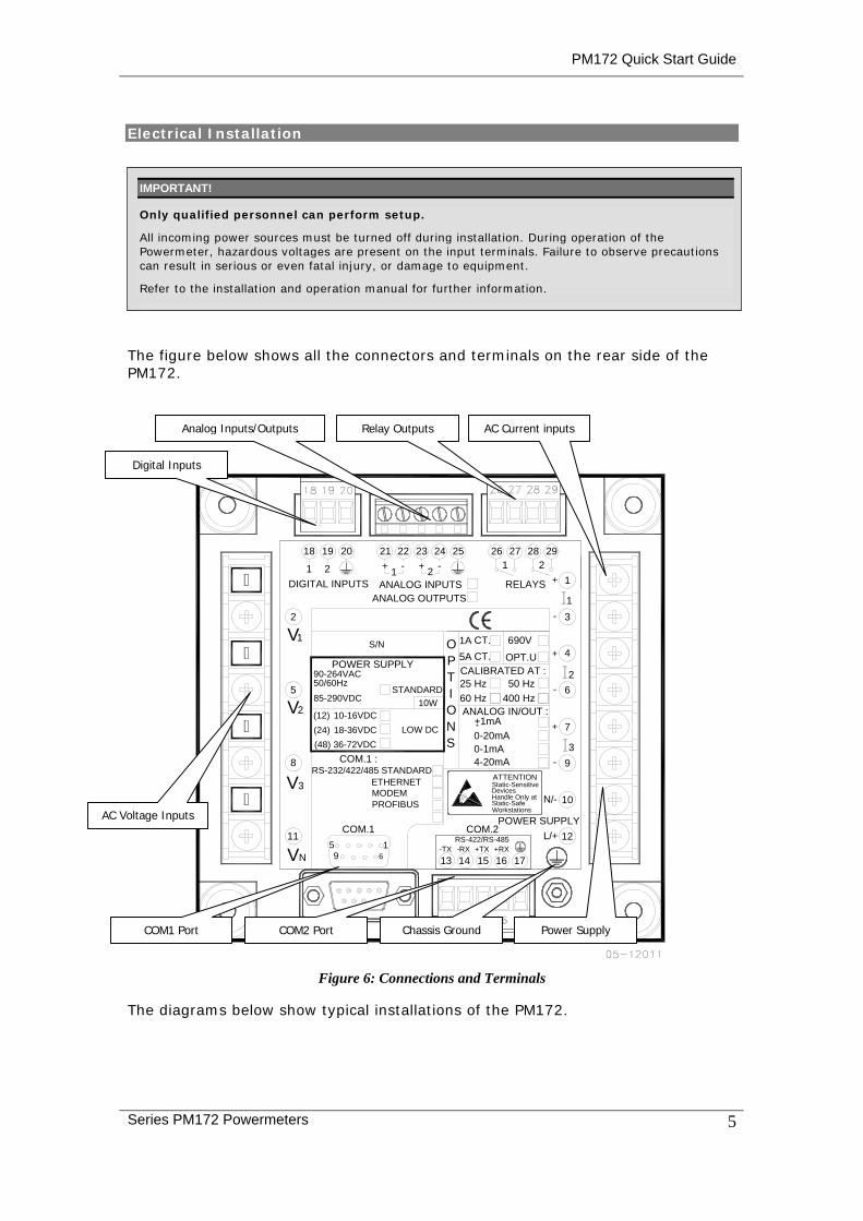
Electrical Installation
The figure below shows all the connectors and terminals on the rear side of the PM172.
+RX16
RS-422/RS-485
POWER SUPPLY
-RX-TX +TXVN 9 6 1413 15
115
V3
8
Handle Only at
COM.11
WorkstationsStatic-Safe
COM.2
Static-SensitiveDevices
ATTENTION
17
N/-
L/+ 12
10
9
21
10-16VDC18-36VDC36-72VDC
2V5
(24)(48)
(12) O
S/N
SNLOW DC
CT.
I
1A
T
DIGITAL INPUTS
90-264VAC50/60Hz85-290VDC
POWER SUPPLY
V1
2
10W
OP
ANALOG OUTPUTS
2018 19
1 2
23+
21 22+
262524
3
7
62
4
1- 3
RELAYS + 1
29282721
ANALOG INPUTS
ANALOG IN/OUT :+1mA-0-20mA
4-20mA0-1mA
+
+
-
-
- -
CALIBRATED AT :25 Hz60 Hz
50 Hz400 Hz
COM.1 :RS-232/422/485 STANDARD
ETHERNETMODEMPROFIBUS
690V
OPT.U
STANDARD
CT.5A
Figure 6: Connections and Terminals
The diagrams below show typical installations of the PM172.
Digital Inputs
Analog Inputs/Outputs Relay Outputs AC Current inputs
Chassis Ground
AC Voltage Inputs
COM1 Port COM2 Port Power Supply
IMPORTANT! Only qualified personnel can perform setup.
All incoming power sources must be turned off during installation. During operation of the Powermeter, hazardous voltages are present on the input terminals. Failure to observe precautions can result in serious or even fatal injury, or damage to equipment.
Refer to the installation and operation manual for further information.
PM172 Quick Start Guide
6 Series PM172 Powermeters
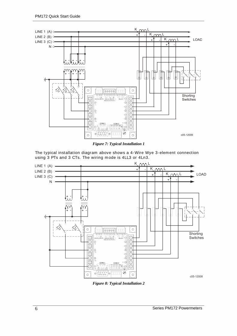
Figure 7: Typical Installation 1
The typical installation diagram above shows a 4-Wire Wye 3-element connection using 3 PTs and 3 CTs. The wiring mode is 4LL3 or 4Ln3.
Figure 8: Typical Installation 2

PM172 Quick Start Guide
Series PM172 Powermeters 7
The typical installation diagram above shows a 4-Wire Wye 2½-element connection using 2 PTs and 3 CTs. The wiring mode is 3LL3 or 3Ln3. The voltages must be balanced for the configuration to provide accurate power measurements.
There are approximately nine different wiring configurations in the PM17X Series. Refer to the Installation and Operational Manual for additional configurations.
For electrical installation of the display panel follow the following steps:
1. Connect the remote display using the pinout tables below, either for a self-powered display or a remote powered display. Refer to the Installation and Operation Manual for the wiring schematic diagrams.
Pinout for a self-powered remote display
PM172 D15 Female Pinout
Signal
Remote Display D15 Male Pinout
1 +12V 1
5 RS-485 + (plus) 5
7 RS-485 - (minus) 7
8 GND 8
15 Chassis 15
Pinout for a remote display powered from an external 12V DC, 350 mA power source
PM172 D15 Female Pinout
Signal
Remote Display D15 Male Pinout
1 N.C. +12V 1
5 RS-485 + (plus) 5
7 RS-485 - (minus) 7
8 N.C. GND 8
15 Chassis 15
2. Connect the DC or AC power.
3. Connect the chassis ground.
4. Connect the required wiring configuration.
5. Connect the I/O connections as required. For I/O ratings, see the Technical Specifications section in the Installation and Operation Manual.
Using the Navigation Buttons
Figure 9: Navigation Buttons
PM172 Quick Start Guide
8 Series PM172 Powermeters
Setup is performed directly from the display panel or via the communication ports using PAS communication software.
In Data Display mode, the navigation buttons function as follows.
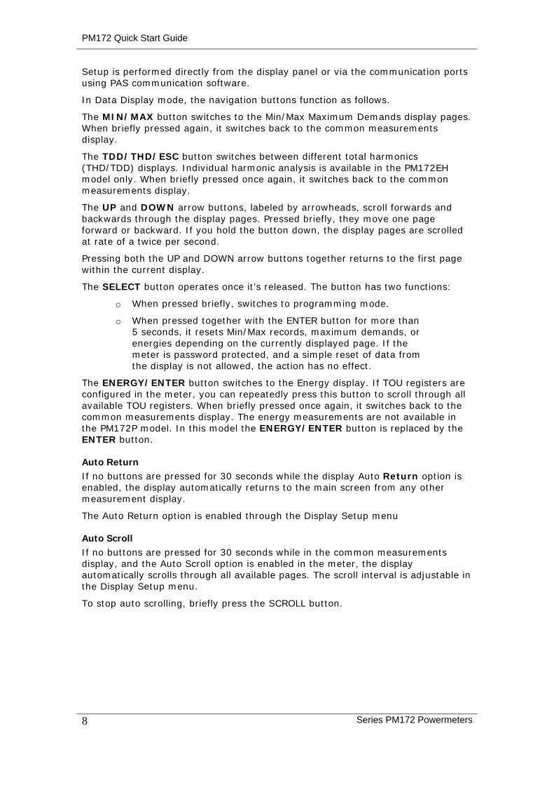
The MIN/MAX button switches to the Min/Max Maximum Demands display pages. When briefly pressed again, it switches back to the common measurements display.
The TDD/THD/ESC button switches between different total harmonics (THD/TDD) displays. Individual harmonic analysis is available in the PM172EH model only. When briefly pressed once again, it switches back to the common measurements display.
The UP and DOWN arrow buttons, labeled by arrowheads, scroll forwards and backwards through the display pages. Pressed briefly, they move one page forward or backward. If you hold the button down, the display pages are scrolled at rate of a twice per second.
Pressing both the UP and DOWN arrow buttons together returns to the first page within the current display.
The SELECT button operates once it’s released. The button has two functions:
o When pressed briefly, switches to programming mode.
o When pressed together with the ENTER button for more than 5 seconds, it resets Min/Max records, maximum demands, or energies depending on the currently displayed page. If the meter is password protected, and a simple reset of data from the display is not allowed, the action has no effect.
The ENERGY/ENTER button switches to the Energy display. If TOU registers are configured in the meter, you can repeatedly press this button to scroll through all available TOU registers. When briefly pressed once again, it switches back to the common measurements display. The energy measurements are not available in the PM172P model. In this model the ENERGY/ENTER button is replaced by the ENTER button.
Auto Return If no buttons are pressed for 30 seconds while the display Auto Return option is enabled, the display automatically returns to the main screen from any other measurement display.
The Auto Return option is enabled through the Display Setup menu
Auto Scroll If no buttons are pressed for 30 seconds while in the common measurements display, and the Auto Scroll option is enabled in the meter, the display automatically scrolls through all available pages. The scroll interval is adjustable in the Display Setup menu.
To stop auto scrolling, briefly press the SCROLL button.
PM172 Quick Start Guide
Series PM172 Powermeters 9
Basic Setup
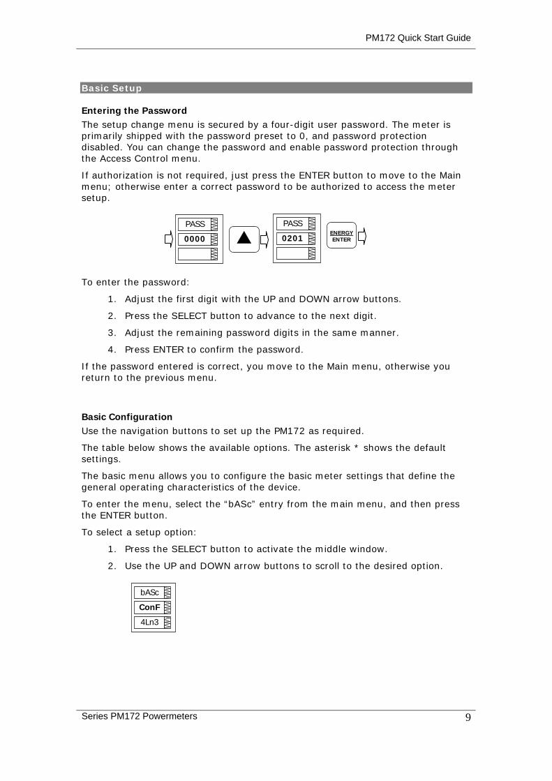
Entering the Password The setup change menu is secured by a four-digit user password. The meter is primarily shipped with the password preset to 0, and password protection disabled. You can change the password and enable password protection through the Access Control menu.
If authorization is not required, just press the ENTER button to move to the Main menu; otherwise enter a correct password to be authorized to access the meter setup.
To enter the password:
1. Adjust the first digit with the UP and DOWN arrow buttons.
2. Press the SELECT button to advance to the next digit.
3. Adjust the remaining password digits in the same manner.
4. Press ENTER to confirm the password.
If the password entered is correct, you move to the Main menu, otherwise you return to the previous menu.
Basic Configuration Use the navigation buttons to set up the PM172 as required.
The table below shows the available options. The asterisk * shows the default settings.
The basic menu allows you to configure the basic meter settings that define the general operating characteristics of the device.
To enter the menu, select the “bASc” entry from the main menu, and then press the ENTER button.
To select a setup option:
1. Press the SELECT button to activate the middle window.
2. Use the UP and DOWN arrow buttons to scroll to the desired option.
bASc
4Ln3
ConF
PASS
0000 ENERGYENTER
PASS
0201

PM172 Quick Start Guide
10 Series PM172 Powermeters
To change the option:
1. Press the SELECT button to activate the lower window.
2. Use the UP and DOWN arrow buttons to select the desired option.
3. Press ENTER to confirm your changes and to store your new setting, or press ESC to discard changes. The table below lists the available options.
4. Press ESC to exit the menu.
Label Parameter Options Default Description
ConF Wiring connection (configuration) mode
3OP2 4LN3 3DIR2 4LL3 3OP3 3LN3 3LL3 3BLN3 3BLL3
4Ln3 The wiring connection of the device
Pt PT ratio 1.0-6500.0 1.0 The phase potential transformer’s primary to secondary ratio
Pt.F PT Ratio multiplier ×1, ×10 ×1 PT Ratio multiplication factor. Used in extra high voltage networks to accommodate the PT ratio for 500 kV and higher networks.
U.SEC Nominal secondary voltage
10-690 V 120 V The nominal secondary line-to-neutral (in configurations with a neutral wire) or line-to-line voltage (in 3OP2, 3OP3 and 3DIR modes) voltage. Used as a reference voltage for the EN50160 evaluation.
Ct CT primary current 1-20,000 A 5 A The primary rating of the phase current transformer
d.P Power block demand period
1, 2, 3, 5, 10, 15, 20, 30, 60 min, E=external sync
15 min The length of the demand period for power demand calculations. If the external synchronization is selected, a pulse front on the digital input DI1 denotes the start of the demand interval.
nd.P The number of blocks in the sliding window
1-15 1 The number of blocks to be averaged for sliding window demands
Ad.P Ampere, volt and THD demand period
0-1800 sec 900 sec The length of the demand period for ampere, volt and THD demand calculations
Freq Nominal frequency 50,60 Hz 60 Hz The nominal line frequency
LoAd Maximum demand load current
0-10000 A 0 The maximum demand load current (0 = CT primary)
Always specify the wiring mode and transformer ratings prior to setting up setpoints and analog outputs.
The maximum value for the product of the phase CT primary current and PT ratio is 57,500,000. If the product is greater, power readings are zeroed.
PM172 Quick Start Guide
Series PM172 Powermeters 11
Setting the Communications You communicate with the meter via a changeable COM1 communication port, or through a second factory set serial RS-485/RS-422 COM2 port.
Communications Connections Several communication options are available for the PM172:
• COM1 (check the label on the back of your meter):
RS-232/RS-422/RS-485
56K Dial-up modem
Ethernet 10/100BaseT
Profibus DP
• COM2:
RS-422/RS-485
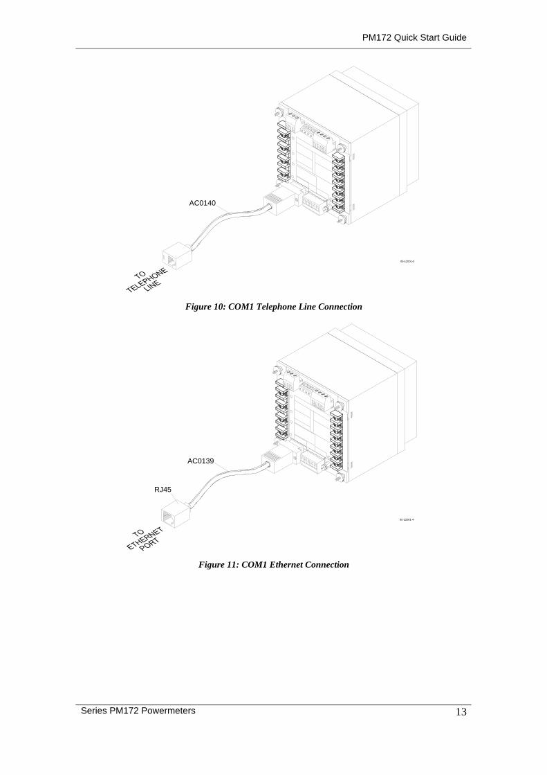
The RS-232/RS-422/RS-485 port is the standard port for COM1. Other options are ordered separately. Connections to the Ethernet RJ45 connector and to the telephone RJ11 connector are made through a cable adaptor provided with your meter (if ordered).
A full description of the communication protocols is found in the PM172 protocol guides provided with your meter.
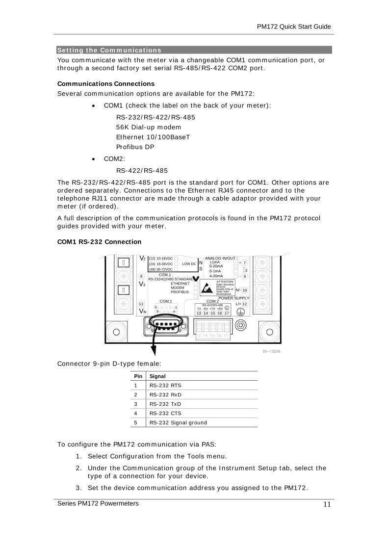
COM1 RS-232 Connection
0-1mA0-20mA
V-+1mALOW DC N(24) 18-36VDC
(48) 36-72VDC S
2 (12) 10-16VDC+ 7
3
9 6
5 1
-4-20mA 98 COM.1 :
ATTENTION
DevicesStatic-Sensitive
Static-SafeWorkstations
Handle Only at
POWER SUPPLY
RS-422/RS-485
16+RX
COM.2COM.111
V 1513 1469N15 -TX +TX-RX
VMODEMPROFIBUS
ETHERNETRS-232/422/485 STANDARD
3
17
12L/+
N/- 10
ANALOG IN/OUT :
Connector 9-pin D-type female:
Pin Signal
1 RS-232 RTS
2 RS-232 RxD
3 RS-232 TxD
4 RS-232 CTS
5 RS-232 Signal ground
To configure the PM172 communication via PAS:
1. Select Configuration from the Tools menu.
2. Under the Communication group of the Instrument Setup tab, select the type of a connection for your device.
3. Set the device communication address you assigned to the PM172.

PM172 Quick Start Guide
12 Series PM172 Powermeters
4. In the Sampling Rate box, select a rate at which PAS updates data on your screen when you continuously poll the device in the PAS Data Monitor.
The communication protocol and port settings in PAS must match the settings made in your device.
COM1 Settings Code Parameter Options Description
Prot Communications protocol ASCII, rtu*, dnP3 ASCII, Modbus RTU or DNP3.0 protocol
rS Port Interface, depends on order
232 = RS-232 485 = RS-485 422 = RS-422 dial = Dial-up Modem Eth.= Ethernet
For non-serial interfaces this is not changeable, it is automatically detected by the meter
Addr Device Address Modbus: 1 (default) -247 DNP3.0: 0 (default) -255
bAud Baud rate 300 - 115,200 bps (19,200 bps*)
dAtA Data format 7E, 8E (7/8 bits, even parity), 8N* (8 bits, no parity) 7E data format should not be used with the Modbus RTU and DNP3 protocols
H.Sh Handshaking (flow control) nonE*=no flow control SOFt=software (XON/XOFF) HArd=hardware (CTS)
rtS RTS mode nonE* = not used Forc = RTS is permanently asserted CtrL = RTS is asserted during the transmission
COM2 Settings Code Parameter Options Description
Prot Communications protocol Rtu* = Modbus RTU ASCII = Modbus ASCII dnP3 = DNP3
The communications protocol supported by the port
rS Port Interface 485* = RS-485 422 = RS-422
Addr Address Modbus: 1*-247 DNP3: 0–65532
Device network address
bAud Baud rate 300-115,200 bps (19,200 bps*)
The port baud rate.
dAtA Data format and parity 7E, 8N*, 8E 7E data format should not be used with the Modbus RTU and DNP3 protocols
PM172 Quick Start Guide
Series PM172 Powermeters 13
05-12001-3
AC0140
Figure 10: COM1 Telephone Line Connection
AC0139
05-12001-4
RJ45
Figure 11: COM1 Ethernet Connection

PM172 Quick Start Guide
14 Series PM172 Powermeters
Communicating via the Internet If you are communicating through the Ethernet port, define the IP address of your meter on the network.
1. On the Instrument Setup tab, select Internet Site.
2. Click on the Connection tab.
3. Select the IP Address and type in the IP address of your meter. The default IP address preset at the factory is 192.168.0.203.
4. In the Protocol box, select the communications protocol for the TCP port. The meter can provide Modbus/TCP connections on TCP port 502 and DNP3/TCP connections on port 20000. The host port is set automatically as you select the protocol. Select Modbus RTU for Modbus/TCP or DNP3 for DNP3/TCP.
5. In the Wait for Answer box, adjust the time that PAS waits for a connection before announcing an error and the number of retries PAS uses to receive a response from the device if communications fail.
Input and Output Ratings
690 V: (standard)
DIRECT INPUT - Nominal: 690V line-to-line voltage, 790V maximum; 400V line-to-neutral, 460V maximum - Burden: <0.4 VA. INPUT USING PT - Burden: <0.15 VA
120 V: (optional) INPUT USING PT - Nominal: 120V line-to-line voltage, 144V maximum - Burden: <0.04 VA
3 voltage inputs
Voltage input terminals Maximum wire section: 4 mm2 (10 AWG)
5A: (standard)
INPUT VIA CT with 5A secondary output - Burden: 2.5 to 4 mm2 (13-11 AWG) wire from CT. Operating range: continuous 10A RMS Burden: < 0.1 VA Overload withstand: 15A RMS continuous, 10A RMS for 1 second. 3 current inputs
(Galvanically isolated)
1A:(optional)
INPUT VIA CT with 1A secondary output - Burden: 2.5 to 4 mm2 (13-11 AWG) wire from CT. Operating range: continuous 2A RMS Burden: < 0.02 VA Overload withstand: 3A RMS continuous, 80A RMS for 1 second.
EIA RS-485 standard Optically isolated, max. speed 115.2Kb/s Communication port COM1 COM1 terminals 3 x Maximum wire section: 2.5 mm2 (12 AWG)
Profibus Max. speed 12 Mb/s Communication port COM1 (Optional) Profibus terminals
5 x Maximum wire section: 2.5 mm2 (12 AWG) or using terminal to DB9 converter: P/N AC0153 REV.A2
Ethernet 10/100 Base T, auto adaptation speed, Max. speed 100Mb/s Communication port
COM2 (Optional) ETH connector Shielded RJ45 cable
120/230 V AC/DC (standard)
85-265VAC, 88-290VDC; 50/60/400 Hz 9VA
12 VDC (optional) 9.5-18 VDC
24/48 VDC (optional) 18.5-72 VDC
Power Supply (Galvanically isolated)
Power Supply input terminals
3 x Maximum wire section: 2.5 to 4 mm2 (13-11 AWG)