Embed Size (px)
Citation preview

Quick Start Guide Cole-Parmer USB-based Data Acquisition Software
Cole-Parmer Instrument Company
625 East Bunker Court Vernon Hills, Illinois 60061-1844
(847) 549-7600 (847) 247-2929 (Fax)
800-323-4340 www.coleparmer.com
e-mail: [email protected] Document Revision 2, February, 2008
© Copyright 2008 Measurement Computing Corporation, QSGR7

2 SM CP-Quick-Start.doc
Table of Contents
About Cole-Parmer data acquisition software ................................................. 3 ■■ System requirements .................................................................................................. 3
Universal Library ................................................................................................................... 4 TracerDAQ ............................................................................................................................ 4 Universal Library for LabVIEW ............................................................................................ 4 Hardware Manuals ................................................................................................................. 5
■■ For More Information… ............................................................................................ 5
Installing the Cole-Parmer DAQ software ........................................................ 6
Running InstaCal and adding your hardware .................................................. 8 ■■ Run InstaCal and add the DEMO-BOARD ............................................................... 8
Configuring and testing the DEMO-BOARD with InstaCal ............................ 11 ■■ Configuring channel 0 on the DEMO-BOARD ....................................................... 11 ■■ Testing channel 0 on the DEMO-BOARD .............................................................. 11
Plotting and generating data with TracerDAQ ............................................... 13 ■■ Acquiring and logging data with the Strip Chart ..................................................... 14
Configuring the Strip Chart ................................................................................................. 14 ■■ Acquiring data with the Oscilloscope ...................................................................... 17
Configuring the Oscilloscope .............................................................................................. 17 ■■ Generating waveforms with the Function Generator ............................................... 19
Adding a Cole Parmer analog output device to InstaCal...................................................... 19 Configuring and running the Function Generator ................................................................ 21
■■ Generating waveforms with the Rate Generator ...................................................... 23 Adding a Cole-Parmer counter output device to InstaCal .................................................... 23 Configuring and running and the Rate Generator ................................................................ 24
Getting started with the Universal Library ..................................................... 26
Getting started with the Universal Library for LabVIEW ............................... 28
Opening your Cole-Parmer hardware user's guides ..................................... 30
Problems installing or running your Cole-Parmer DAQ software? .............. 31

3
About Cole-Parmer data acquisition software
This Quick Start Guide contains the latest information on installing the
Cole-Parmer Data Acquisition Software you received with your Cole-
Parmer hardware. Please read this booklet completely before you install
any software or hardware.
Cole-Parmer's data acquisition software includes the following software
packages:
InstaCal & Universal Library — Installation, calibration, and test
utility, and programming library for Cole-Parmer data acquisition
hardware.
TracerDAQ — Professional-grade Strip Chart, Oscilloscope,
Function Generator, and Rate Generator applications.
Universal Library for LabVIEW™ — LabVIEW drivers for Cole-
Parmer data acquisition devices.
Hardware User's Guides — Hardware user's guides for Cole-
Parmer data acquisition devices.
You select the packages that you want to install from the software
installation dialog.
■■ System requirements
You can install this Cole-Parmer Data Acquisition Software package on
a computer running one of these operating systems:
Windows 2000 with Service Pack 4 (SP4)
Windows XP with Service Pack 2 (SP2)
Windows VISTA 32-bit
These operating systems are the only requirements for running InstaCal.
The hardware and software requirements for the other packages are
listed next.

About Cole-Parmer data acquisition software
4
Universal Library
Application development software that supports one or more of these
32-bit languages.
Microsoft® Windows® languages: Visual Basic and Visual C/C++
.NET languages: VB .NET, C# .NET (Visual Studio® 2003 and
2005)
Borland® Windows languages: Borland C++, Borland C++
Builder®, Delphi®
TracerDAQ
You can run TracerDAQ on a computer running one of the following
operating systems and software.
Microsoft®
Windows 2000 (SP4), Windows XP (SP2), Windows
Vista
Microsoft .NET® Framework 2.0
DirectX 9.0c
InstaCal
TracerDAQ installation automatically installs the Microsoft .NET®
Framework 2.0 and DirectX 9.0c if these applications are not already
installed.
Hardware requirements
Video card with 16 MB of memory and support for Direct3D
Acceleration
Minimum screen resolution of 1024 x 768
Computer with Pentium® 4 processor and 256 MB of RAM
A Microsoft-compatible mouse
Supported Cole-Parmer data acquisition hardware (refer to the
readme.txt file installed with the software for a list of supported
hardware).
Universal Library for LabVIEW
InstaCal & Universal Library
LabVIEW 6.0 or later

About Cole-Parmer data acquisition software
5
Hardware Manuals
Software requirements:
Adobe®
Reader®
Adobe Reader is automatically selected if you select to install the
hardware manuals and do not have this program currently installed.
If you do not install the Cole-Parmer hardware manuals during the DAQ
software installation, you can open or copy these documents from the
ICalUL/Documents/UsersGuides folder on the Cole-Parmer DAQ
Software CD.
To use Cole-Parmer DAQ software with a Cole-Parmer device, install
the latest Windows Update. You can run Windows Update from
http://update.microsoft.com/windowsupdate/v6/default.aspx?ln=en-us.
■■ For More Information…
If you have questions that you cannot answer by reading this booklet,
refer to these resources.
Cole-Parmer web site – www.coleparmer.com
Tech support contact information:
Phone: 847-549-7600
800-323-4340
Fax: 847-247-2929
Email: [email protected]

6
Installing the Cole-Parmer DAQ software
The DAQ Software installation program consists of a series of
easy-to-follow dialogs that lead you through the installation procedure.
To install the Cole-Parmer DAQ software, do the following.
1. Insert the Cole-Parmer Data Acquisition Software CD in your CD
drive and wait for the installation program to start.
If the installation program does not start automatically, use
Windows Explorer to browse to the root of the CD, and
double-click on .
The DAQ Software dialog opens.
All software packages are selected for installation ( ) by default if
the requirements for the package are met.
○ When you click on a package, a brief description of it appears
in the Description frame, along with the requirements to install that package.
○ After you click on a package, you can click on the View
ReadMe button to view the readme file for that package.

Installing the Cole-Parmer DAQ software
7
2. If you do not want to install a software package, click on the check
box next to it to uncheck it ( ).
The Required dependencies area of the dialog lists the software
packages needed to run the Cole-Parmer DAQ software you
selected to install. This area may be blank, or may list one or more
of the following packages.
Adobe Reader - Adobe Reader is required to read the hardware
manuals. If you do not have Adobe Reader installed, it is selected in
the Required dependencies area.
If you have an earlier version already installed, installing the latest
version is optional. Deselect the Adobe Reader check box to keep
your currently installed version.
Microsoft .NET framework - The .NET Framework 2.0 is
required to install TracerDAQ and the hardware user's guides. If the
framework is not detected on your PC, this package is listed and the
checkbox checked. In this case, it is recommended that you leave
the Microsoft .NET framework check box checked. If you uncheck
the Microsoft .NET framework check box, the TracerDAQ and
Hardware Manuals check boxes become disabled, the Adobe
Reader check box becomes unchecked, and these software packages
do not get installed.
3. Click on the Install button and follow the instructions on the
installation dialogs.
If Microsoft .NET framework was listed and checked in the
Required dependencies area, the install program installs version 2.0
of the .NET framework before launching the InstaCal & Universal
Library installation program. The installation program automatically
installs each selected software product in succession. After all of the
selected Cole-Parmer DAQ components are installed, a dialog
opens which allows you to install Adobe Acrobat Reader.
Installation of InstaCal & Universal Library requires you to restart your
computer after installing. You are prompted to restart your computer
after all of the selected products are installed.
8
Running InstaCal and adding your hardware
This section contains hands-on examples that show you how to
configure and test your hardware using InstaCal and the DEMO-
BOARD, which is a virtual ISA data acquisition board.
■■ Run InstaCal and add the DEMO-BOARD
This section explains how to run InstaCal and add the DEMO-BOARD
to the InstaCal configuration.
1. To run InstaCal, click on Start►All Programs►Cole
Parmer►InstaCal.
InstaCal's main form opens.

Running InstaCal and adding your hardware
9
2. Click the right mouse button on the PC Board List, and select Add
Board… from the popup menu.
The Board Selection List dialog opens.
3. Click on the ISA tab.
4. Scroll down to select DEMO-BOARD, and then click on the Add
button.
The DEMO-BOARD is added to InstaCal's main form.

Running InstaCal and adding your hardware
10
Now that you have added the DEMO-BOARD you can use this form to
configure and test the DEMO-BOARD.

11
Configuring and testing the DEMO-BOARD with InstaCal
You can configure and test the DEMO-BOARD with InstaCal.
For other Cole-Parmer devices, the available configuration settings and
testing options vary depending on the type of device and the features it
offers.
■■ Configuring channel 0 on the DEMO-BOARD
In the following example, you use InstaCal to change the configuration
of channel 0 on the DEMO-BOARD.
1. On the PC Board List, double-click on the DEMO-BOARD item.
The Board Configuration dialog for the DEMO-BOARD opens.
2. Change the input type for channel 0 from Sine Wave to Damped Sine Wave, and click on the OK button to close the dialog.
Now, you can run a test using InstaCal to make sure the DEMO-
BOARD's channel 0 generates a damped sine wave.
■■ Testing channel 0 on the DEMO-BOARD
InstaCal includes options to test the analog and/or digital features of
your Cole-Parmer hardware.
For the DEMO-BOARD, you can run an analog loop back test to make
sure a channel is generating the proper waveform.

Configuring and testing the DEMO-BOARD with InstaCal
12
1. Make sure the DEMO-BOARD is still selected on the PC Board
List.
2. From the Test menu, select Analog.
The Board Test: DEMO-BOARD at 0h dialog opens.
3. Make sure Ch 0 is selected in the Input Ch drop-down list, and a
damped sine wave shows on the display. Then click on the OK
button to close the dialog.
4. From the File menu, select Exit to close the InstaCal.
Next, you will learn how to run TracerDAQ's Strip Chart application to
acquire, plot, and log data from four channels on the DEMO-BOARD.

13
Plotting and generating data with TracerDAQ
TracerDAQ includes the following applications:
Strip Chart with data logging functionality
Oscilloscope
Function Generator
Rate Generator.
Hands-on examples for each TracerDAQ application are included in the
following sections.
After you configure and test your hardware with InstaCal, you can run
TracerDAQ and use the DEMO-BOARD with the Strip Chart and
Oscilloscope.
To run TracerDAQ, click on Start►Programs►Cole
Parmer►TracerDAQ►TracerDAQ.
The TracerDAQ dialog opens. You can run any of the four
TracerDAQ applications from this dialog.

Plotting and generating data with TracerDAQ
14
■■ Acquiring and logging data with the Strip Chart
Use the Strip Chart to acquire and log data from up to eight analog
input, temperature input, digital input, or event counter channels
To run the Strip Chart, highlight it on the application list, and then click
the Run button.
The Strip Chart window opens.
Configuring the Strip Chart
Once the Strip Chart window is open, you need to select the hardware,
channel(s), and data range used as the data source.
1. From the File menu, select New.... The DAQ Hardware Settings
dialog opens.
2. From the first row of the DAQ Device column, select the DEMO-
BOARD from the list-box.
The drop-down list shows the device ID and device name for all
boards that are configured by InstaCal. When you select a device,
the first channel and range supported by the device appear in the
DAQ Channel and DAQ Range/Mode columns.
3. Right-mouse click on the first column, and select AutoFill All from
the popup menu. This automatically configures the DAQ Device,
DAQ Channel and DAQ Range/Mode for the remaining channels on
the dialog.

Plotting and generating data with TracerDAQ
15
The dialog automatically becomes configured to acquire data from
four channels on the DEMO-BOARD.
4. Click on the OK button to save the settings and close the dialog.
5. Acquiring and plotting data with the Strip Chart
6. Click the Run button ( ) on the Strip Chart to start acquiring data
from the DEMO-BOARD.
The Strip Chart acquires and displays data from the first four
channels (0 -3) of the DEMO-BOARD.

Plotting and generating data with TracerDAQ
16
7. To stop the scan, click on the Stop button ( ).
That's all there is to it! The Strip Chart provides many options for
working with Strip Chart data and customizing the Strip Chart display.
To learn more about the Strip Chart, select TracerDAQ Help from
TracerDAQ's Help menu.
Additional features available in TracerDAQ Pro's Strip Chart If you upgrade to TracerDAQ Pro, you can also:
▪ acquire and plot data from up to 32 channels
▪ acquire and plot up to 1 million samples per channel
▪ set alarm conditions
▪ set software, hardware, and time-of-day triggering
▪ apply linear scaling
To learn about these and other Strip Chart features available only with
TracerDAQ Pro, contact Cole-Parmer at 800-323-4340.

Plotting and generating data with TracerDAQ
17
■■ Acquiring data with the Oscilloscope
Use the Oscilloscope to acquire and plot data from up to two analog
input channels.
To run the Oscilloscope, highlight it on the application list, and then
click the Run button.
The Oscilloscope window opens.
Configuring the Oscilloscope
Once the Oscilloscope window is open, you need to select the hardware,
channel(s), and data range used as the data source.
1. From the File menu, select New.... The DAQ Hardware Settings
dialog opens.
2. From the first row of the DAQ Device column, select the DEMO-
BOARD from the list-box.
The drop-down list shows the device ID and device name for all
boards that are configured by InstaCal. When you select a device,
the first channel and the default range supported by the device
appear in the DAQ Channel and DAQ Range/Mode columns.
3. Right-mouse click on the first column, and select AutoFill All from
the pop up menu. This automatically configures the DAQ Device,
DAQ Channel and DAQ Range/Mode for the remaining channel on
the dialog.

Plotting and generating data with TracerDAQ
18
4. Click on the DAQ Range/Mode column's down arrow and select
+/-5V. The range automatically updates for both channels.
5. On the Oscilloscope window, click on the Start button ( ).
6. The Oscilloscope acquires and displays data from the first two
channels (0 - 2) of the DEMO-BOARD.
7. To stop the scan, click on the Stop button ( ).
That's all there is to it! The Oscilloscope provides many options for
working with Oscilloscope data and customizing the Oscilloscope
display. To learn more about the Oscilloscope, select TracerDAQ Help
from TracerDAQ's Help menu.
Additional features available in TracerDAQ Pro's Oscilloscope If you upgrade to TracerDAQ Pro, you can also:
▪ acquire and plot data from up to four analog input channels
▪ set up a reference and math channel
To learn about these and other Oscilloscope features available only with
TracerDAQ Pro, contact Cole-Parmer at 800-323-4340.

Plotting and generating data with TracerDAQ
19
■■ Generating waveforms with the Function Generator
Use the Function Generator to output sine wave data to one analog
output channel.
To use TracerDAQ's Function Generator application, you first need to
install a Cole-Parmer device with analog output channels and add it to
InstaCal.
In order for the Function Generator to detect this device, you must add it
to InstaCal when TracerDAQ is not running.
1. If you are running any TracerDAQ application, close the application
by selecting Exit from the File menu.
2. Close TracerDAQ by clicking on the Exit button on the main
TracerDAQ dialog.
Adding a Cole Parmer analog output device to InstaCal
This section explains how to run InstaCal and add an analog output
device to the InstaCal configuration.
1. Follow the steps in the analog output device's user guide to install
the device in your computer.
2. Run InstaCal by selecting Start►All Programs►Cole
Parmer►InstaCal.
The Plug and Play Hardware Detection dialog opens with the
analog output device listed.

Plotting and generating data with TracerDAQ
20
3. Select the analog output device you want to add to the InstaCal
configuration file, and then click on the OK button.
This example shows the 18200-10.
The Plug and Play Hardware Detection dialog closes, and the
InstaCal main form becomes active.
4. Use InstaCal to perform any configurations and tests on the device.
When you are done, close InstaCal by selecting Exit from the File
menu.

21
Configuring and running the Function Generator
Now that your analog output device has bee added to InstaCal, you can
run TracerDAQ and access the device from the Function Generator.
To generate a waveform with the Function Generator:
1. Run TracerDAQ by selecting Start►Programs►Cole
Parmer►TracerDAQ►TracerDAQ.
The TracerDAQ dialog opens.
2. To run the Function Generator, highlight it on the application list,
and then click the Run button.
3. The Function Generator window opens.
4. Select New... from the File menu. The DAQ Hardware Settings
dialog opens.
5. From the first row of the DAQ Device column, select the analog
output device from the list-box. A 18200-10 is used for this
example.
The drop-down list shows the device ID and device name for all analog output devices that are configured by InstaCal. When you
select a device, the first analog output channel and the default range
supported by the device appear in the DAQ Channel and DAQ
Range/Mode columns.
6. Click on the OK button to save the settings and close the dialog.

Plotting and generating data with TracerDAQ
22
7. Click the Run button ( ) on the Function Generator to start an
output scan that sends waveform data to the configured channel.
The 18200-10 requires a positive DC level setting equal to the
amplitude setting to avoid clipping the waveform at 0 volts.
The Function Generator sends a sine wave pattern with the
amplitude and DC level option settings shown in the example
below.
8. To stop the scan, click on the Stop button ( ).
That's all there is to it! The Function Generator provides many options
that let you change the properties of the waveform, DAQ hardware, and
the Function Generator display. To learn more about the Function
Generator, select TracerDAQ Help from TracerDAQ's Help menu.
Additional features available in TracerDAQ Pro's Function Generator If you upgrade to TracerDAQ Pro, you can also:
▪ generate square, triangle, flat, pulse, ramp, random, and arbitrary
waveforms from a text file (.csv or .txt)
▪ set duty cycle, phase, gate ratio, and rate multiplier options
▪ enable a linear or exponential sweep of the waveform
For more information on TracerDAQ Pro, contact Cole-Parmer at 800-
323-4340.

Plotting and generating data with TracerDAQ
23
■■ Generating waveforms with the Rate Generator
Use the Rate Generator to output data to one counter output channel.
To use TracerDAQ's Rate Generator application, you first need to install
a Cole-Parmer counter output device and configure it in InstaCal.
In order for the Rate Generator to detect this device, you must add it to
InstaCal when TracerDAQ is not running.
1. If you are running any TracerDAQ application, close the application
by selecting Exit from the File menu.
2. Close TracerDAQ by clicking on the Exit button on the main
TracerDAQ dialog.
Adding a Cole-Parmer counter output device to InstaCal
This section explains how to run InstaCal and add a counter output
device to the InstaCal configuration.
1. Follow the steps in the counter output device's user guide to install
the device in your computer.
2. Run InstaCal by selecting Start►All Programs►Cole-
Parmer►InstaCal.
The Plug and Play Hardware Detection dialog opens with the
counter output device listed.

Plotting and generating data with TracerDAQ
24
3. Select the counter output device you want to add to the InstaCal
configuration file, and then click on the OK button.
The Plug and Play Hardware Detection dialog closes, and the
InstaCal main form becomes active.
4. Use InstaCal to perform any configurations and tests on the device.
When you are done, close InstaCal by selecting Exit from the File
menu.
Configuring and running the Rate Generator
Now that your counter output device has been added to InstaCal, you
can run TracerDAQ and access the device from the Rate Generator.
To generate a square waveform with the Rate Generator:
1. Run TracerDAQ by selecting Start►Programs►Cole
Parmer►TracerDAQ►TracerDAQ.
The TracerDAQ dialog opens.
2. To run the Rate Generator, highlight it on the application list, and
then click the Run button.
3. The Rate Generator window opens.
4. Select New... from the File menu. The DAQ Hardware Settings
dialog opens.
5. From the first row of the DAQ Device column, select the counter
output device from the list-box.

Plotting and generating data with TracerDAQ
25
The drop-down list shows the device ID and device name for all
counter output devices that are configured by InstaCal. When you
select a device, the device's first counter output channel appears in
the DAQ Channel column. The DAQ Range/Mode column is
disabled.
6. Click on the OK button to save the settings and close the dialog.
7. Click the Run button ( ) on the Rate Generator to start an output
scan that sends waveform data based on the frequency option
settings to the default channel.
By default, the Rate Generator sends a square wave pattern with the
option settings shown in the example below.
8. To stop the scan, click on the Stop button ( ).
That's all there is to it! The Rate Generator provides many options that
let you change the properties of the waveform, DAQ hardware, and the
Rate Generator display. To learn more about the Rate Generator, select
TracerDAQ Help from TracerDAQ's Help menu.
Additional feature available in TracerDAQ Pro's Rate Generator If you upgrade to TracerDAQ Pro, you can generate waves for up to 20
counter output channels.
For more information on TracerDAQ Pro, contact Cole-Parmer at 800-
323-4340.
Getting started with the Universal Library
26
Getting started with the
Universal Library
The Universal Library provides a programming library you can use to
develop applications that control Cole-Parmer hardware.
The Universal Library supports programming in Visual Basic, VB .NET
Visual C/C++, C# .NET, Borland C++, Delphi, and other languages.
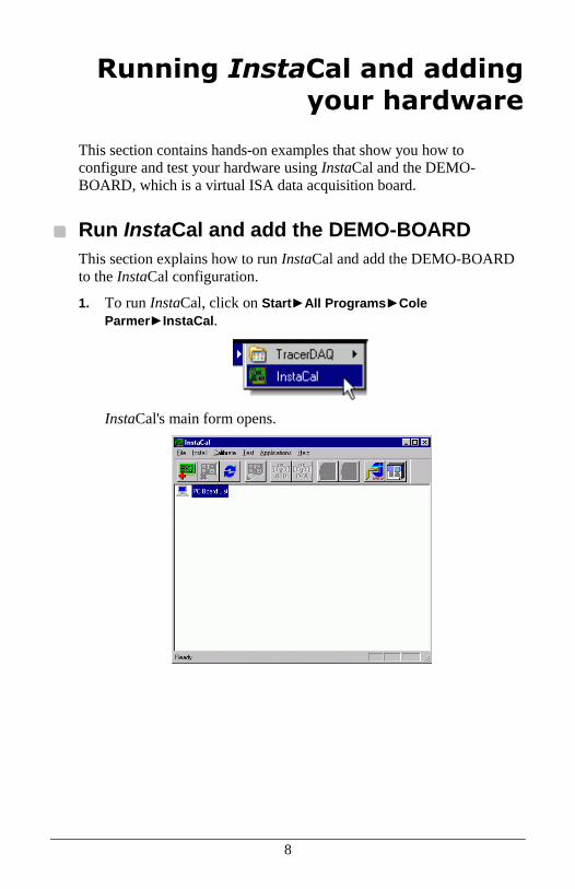
The Universal Library is automatically installed with InstaCal. The
default installation directory is \Program Files\Cole Parmer\DAQ.
If you are running Windows 2000 or XP, and chose to install the
Universal Library examples, they are installed in individual sub-
folders in the DAQ folder, as shown here.
If you are running Windows Vista, and chose to install the
Universal Library examples, they are installed in individual sub-
folders in the Users\Public\PublicDocuments\Cole Parmer\DAQ
folder, as shown here.

Getting started with the Universal Library
27
There are shortcuts to this folder on the Windows Vista Start
menu…
…and in the \Program Files\Cole Parmer\DAQ folder.
To learn about the Universal Library functions and how to use them
with Cole-Parmer hardware, refer to the Universal Library help file
(ULHelp.chm) located in the DAQ folder.

28
Getting started with the Universal Library for LabVIEW
The Universal Library for LabVIEW provides drivers that enable you to
create LabVIEW applications that control Cole-Parmer hardware.
If you installed the Universal Library for LabVIEW, example programs
are installed by default to the \Program Files\National
Instruments\LabVIEW X.x/examples/Universal Library folder (where
X.x is the version of LabVIEW you have installed).
To build an application from scratch, launch LabVIEW, create a new
project, and then do the following:
1. Make the Diagram window of the project the active window. If the
Panel window is currently active, select the Show Diagram option
from the Window menu.
1. From the Diagram window, select the Show Functions Palette
option from the Window menu to open the Functions palette.
2. From the Functions palette, click on the User Libraries icon to open
the User Libraries palette.
3. From the User Libraries palette, click on the MCC icon to open the
MCC Data Acquisition palette.
4. Select the VI you want to use by clicking on the appropriate icon.
Move the cursor back to the Diagram window and click to place the
VI.
Getting started with the Universal Library for LabVIEW
29
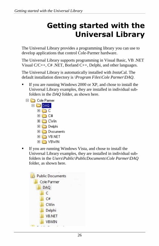
After placing the VIs you want to use on the Diagram window, you can
wire them together. Save the application prior to testing.
Refer to the help for information on each VI and its input and output
parameters.
To learn about the Universal Library for LabVIEW VIs, refer to the
Universal Library for LabVIEW help file (ULLVHelp.chm) located by
default in the \Program Files\National Instruments\LabVIEW
X.x\menus\Universal Library folder.

30
Opening your Cole-Parmer hardware user's guides
If you installed the Cole-Parmer hardware user's guides during the DAQ
software installation, you can open your hardware manual right from
within InstaCal.
You need Adobe® Reader® to open the user's guides. You can install
this software from the AcrobatReader folder on the CD.
1. Select User's Guides from InstaCal's Help menu.
2. From the Open dialog, double-click on the USB folder.
3. Double-click on the PDF hardware manual you want to open.
Accessing hardware user's guides from the Cole-Parmer DAQ Software CD If you did not install the Cole-Parmer hardware user's guides during the
DAQ software installation, you can open or copy these documents from
the ICalUL/Documents/UsersGuides folder on the Cole-Parmer DAQ
Software CD.

31
Problems installing or running your Cole-Parmer DAQ
software?
For software and hardware questions:
Phone: 800-323-4340.
Fax: 847-247-2929
Email: [email protected]

32
Trademark and Copyright Information
Cole-Parmer is a registered trademark of Cole-Parmer Instrument Company.
TracerDAQ, Universal Library, Harsh Environment Warranty, Measurement Computing
Corporation, and the Measurement Computing logo are either trademarks or registered
trademarks of Measurement Computing Corporation.
Windows, Microsoft, and Visual Studio are either trademarks or registered trademarks of
Microsoft Corporation
LabVIEW is a trademark of National Instruments.
CompactFlash is a registered trademark of SanDisk Corporation.
All other trademarks are the property of their respective owners.
Information furnished by Measurement Computing Corporation is believed to be accurate
and reliable. However, no responsibility is assumed by Measurement Computing
Corporation neither for its use; nor for any infringements of patents or other rights of
third parties, which may result from its use. No license is granted by implication or
otherwise under any patent or copyrights of Measurement Computing Corporation.
All rights reserved. No part of this publication may be reproduced, stored in a retrieval
system, or transmitted, in any form by any means, electronic, mechanical, by
photocopying, recording, or otherwise without the prior written permission of
Measurement Computing Corporation.

Cole-Parmer Instrument Company 625 East Bunker Court
Vernon Hills, Illinois 60061-1844 (847) 549-7600
Fax: (847) 247-2929 800-323-4340
www.coleparmer.com E-mail: [email protected]