Embed Size (px)
Citation preview

Quick Start Guide
MPC567xK Qorivva MCU Development Board

Quick Start Guide
2
Get to Know the Qorivva MPC567xK Board
LinFlex SCI FlexCAN FlexRay™ DSPI and FlexPWM
Power Switch
Power
EBI
ADC
NMI/FCCU/CG
JTAG/Nexus
User SW and LEDs
Ethernet
Reset
MCU
PDI, eTimer and FEC
mDDR (473BGA Only)
Qorivva MPC567xK
3
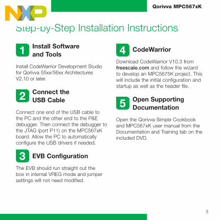
1 Install Software and Tools
Install CodeWarrior Development Studio for Qorivva 55xx/56xx Architectures V2.10 or later.
2 Connect the USB Cable
Connect one end of the USB cable to the PC and the other end to the P&E debugger. Then connect the debugger to the JTAG (port P11) on the MPC567xK board. Allow the PC to automatically configure the USB drivers if needed.
3 EVB Configuration
The EVB should run straight out the box in internal VREG mode and jumper settings will not need modified.
4 CodeWarrior
Download CodeWarrior V10.3 from freescale.com and follow the wizard to develop an MPC5675K project. This will include the initial configuration and startup as well as the header file.
5 Open Supporting Documentation
Open the Qorivva Simple Cookbook and MPC567xK user manual from the Documentation and Training tab on the included DVD.
Step-by-Step Installation Instructions

Quick Start Guide
4
6 Explore Further with the Qorivva Simple Cookbook: Lab Exercise
To run a demonstration using the MP567xK, follow the instructions for the lab exercise for MPC5675K in the Qorivva Simple Cookbook, located under the documentation tab on the DVD.
7 Learn More About the MPC567xK
Read the release notes and documentation located on the DVD and at freescale.com.
a. The Qorivva Simple Cookbook provides simple code examples for manipulating different peripherals on the MPC567xK
b. The RAppID graphical initialization software will help you get to market faster
c. CodeWarrior for 55xx/56xx with examples from the Simple Cookbook

5
Qorivva MPC567xK
MPC5675KEVB257 Jumper OptionsThe following is a list of all the jumper options. The default installed jumper settings are listed in the second column.
Jumper Reference Default Setting Jump
Count Description
J77 ON 1 Has now been removed
J43 ON 1 Power on VDD_HV_IO is enabled
J59 ON 1 VDD_HV_DRAM_REF is enabled
J47 ON 1 Power on VDD_HV_FLA is enabled
J61 ON 1 Power on VDD_HV_PDI is enabled
J41 ON 1 Power on VDD_HV_OSC is enabled
J56 ON 1 Power on VDD_HV_ADV is enabled
J70 Short 1-2 1 Power on VDD_HV_ADR is 5.0 V
J60 OFF 0 Power on VDD_LV_COR is disabled
J53 ON 1 Internal power is enabled
J52 ON 1 Internal power is enabled
J71 Short 2-3 1 Internal power is enabled and 3.3 V to VDD_PMU
J48 Short 2-3 1 Internal power is enabled
J50 Short 1-2 1 VPP_TEST should be grounded
J38 OFF (place on PIN1 only) 1 POTS on ADC0 is disabled
J55 Short 2-3 1 PW_ON_RESET is enabled
J63 Short 1-2 1 MCRGM_FAB is tied to ground

Quick Start Guide
6
Jumper Reference Default Setting Jump
Count Description
J34 Short 1-2 1 MCRGM_ABS0 is tied to ground
J37 Short 1-2 1 MCRGM_ABS2 is tied to ground
J40 Short 1-2 1 Use on-board 40 MHz crystal
J39 Short 1-2 1 Use on-board 40 MHz crystal
J67 OFF (place on PIN1 only) 1 Use on-board 40 MHz crystal
J68 OFF (place on PIN1 only) 1 Use on-board 10 MHz crystal
J46 ON 1 Power on Ethernet PHY is enabled
J30 ON 2 Power on CAN PHY is enabled
J31 ON 2 CANA TXD and RXD are connected to MCU
J22 ON 3 CANA control signals are on
J29 ON 2 CANB TXD and RXD are connected to MCU
J21 ON 3 CANB control signals are on
J18 Short 2-3 1 UART TXD is connected to MCU
J17 Short 2-3 1 UART RXD is connected to MCU
J19 Short 2-3 1 UART TXD is connected to MCU
J20 Short 2-3 1 UART RXD is connected to MCU
J16 ON 1 Power on LINC is enabled
J5 ON 1 LINC bus master mode is enabled
J23 ON 1 Power on LIND is enabled
J6 ON 1 LIND bus master mode is enabled

7
Qorivva MPC567xK
Jumper Reference Default Setting Jump
Count Description
J15 ON 1 Power on SCI is enabled
J28 ON 3 Power on FlexRay is enabled
J26 ON 3 FlexRayA data signals are connected to MCU
J27 ON 4 FlexRayA control signals are on
J24 ON 3 FlexRayB data signals are connected to MCU
J25 ON 4 FlexRayB control signals are on
J13 ON 1 FlexRayA decoupling capacitor is disabled
J12 ON 1 FlexRayA decoupling capacitor is disabled
J10 ON 1 FlexRayB decoupling capacitor is disabled
J11 ON 1 FlexRayB decoupling capacitor is disabled
J78 ON 1 FLEXPWM0_B1 is disable to LED
J79 ON 1 FLEXPWM0_B0 is disable to LED
J80 ON 1 FLEXPWM0_A3 is disable to LED
J81 ON 1 FLEXPWM0_A2 is disable to LED
J82 ON 1 FLEXPWM0_X2 is disable to LED
J83 ON 1 FLEXPWM0_X3 is disable to LED
J84 ON 1 FLEXPWM0_A1 is disable to LED
J85 ON 1 FLEXPWM0_B3 is disable to LED

Quick Start Guide
8
MPC5675KEVB473 Jumper OptionsThe following is a list of all the jumper options. The default installed jumper settings are listed in the second column.
Jumper Reference Default Setting Jump
Count Description
J77 ON 1 Now been removed
J41 ON 1 Power on VDD_HV_IO is enabled
J63 Short 2-3 1 Power on VDD_HV_DRAM is 3.3 V
J58 ON 1 VDD_HV_DRAM_VTT is grounded
J55 ON 1 Power on VDD_HV_FLA is enabled
J56 ON 1 Power on VDD_HV_PDI is enabled
J40 ON 1 Power on VDD_HV_OSC is enabled
J44 ON 1 Power on VDD_HV_ADV is enabled
J78 Short 1-2 1 Power on VDD_HV_ADR is 5.0 V
J46 OFF 0 Power on VDD_LV_COR is disabled
J59 ON 1 Internal power is enabled
J57 ON 1 Internal power is enabled
J79 Short 2-3 1 Internal power is enabled and 3.3 V to VDD_PMU
J62 Short 2-3 1 Internal power is enabled
J83 Short1-2 1 VPP_TEST is tied to GND
J38 OFF (place on PIN1 only) 1 POTS on ADC0 is disabled
J61 Short 2-3 1 PW_ON_RESET is tied to ground

9
Qorivva MPC567xK
J64 Short 1-2 1 MCRGM_FAB is tied to ground
J34 Short 1-2 1 MCRGM_ABS0 is tied to ground
J37 Short 1-2 1 MCRGM_ABS2 is tied to ground
J43 Short 1-2 1 Use on-board 40 MHz crystal
J42 Short 1-2 1 Use on-board 40 MHz crystal
J73 OFF (place on PIN1 only) 1 Use on-board 40 MHz crystal
J74 OFF (place on PIN1 only) 1 Use on-board 40 MHz crystal
J71 Short 1-2 1 Power on PISMO_DM_VCC is 3.3 V
J72 Short 1-2 1 Power on PISMO_DM_VIO is 3.3 V
J48 ON 1 Power on Ethernet PHY is enabled
J30 ON 2 Power on CAN PHY is enabled
J31 ON 2 CANA TXD and RXD are connected to MCU
J22 ON 3 CANA control signals are on
J29 ON 2 CANB TXD and RXD are connected to MCU
J21 ON 3 CANB control signals are on
J18 Short 2-3 1 UART TXD is connected to MCU
J17 Short 2-3 1 UART RXD is connected to MCU
J19 Short 2-3 1 UART TXD is connected to MCU
J20 Short 2-3 1 UART RXD is connected to MCU
J16 ON 1 Power on LINC is enabled
Jumper Reference Default Setting Jump
Count Description

Quick Start Guide
10
J5 ON 1 LINC bus master mode is enabled
J23 ON 1 Power on LIND is enabled
J6 ON 1 LIND bus master mode is enabled
J15 ON 1 Power on SCI is enabled
J28 ON 3 Power on FlexRay is enabled
J26 ON 3 FlexRayA data signals are connected to MCU
J27 ON 4 FlexRayA control signals are on
J24 ON 3 FlexRayB data signals are connected to MCU
J25 ON 4 FlexRayB control signals are on
J13 ON 1 FlexRayA decoupling capacitor is disabled
J12 ON 1 FlexRayA decoupling capacitor is disabled
J10 ON 1 FlexRayB decoupling capacitor is disabled
Jumper Reference Default Setting Jump
Count Description

11
Qorivva MPC567xK
Jumper Reference Default Setting Jump
Count Description
J11 ON 1 FlexRayB decoupling capacitor is disabled
J39 ON 1 FLEXPWM0_B1 is enabled to LED
J49 ON 1 FLEXPWM0_B0 is enabled to LED
J50 ON 1 FLEXPWM0_A3 is enabled to LED
J52 ON 1 FLEXPWM0_A2 is enabled to LED
J54 ON 1 FLEXPWM0_X2 is enabled to LED
J80 ON 1 FLEXPWM0_X3 is enabled to LED
J81 ON 1 FLEXPWM0_A1 is enabled to LED
J82 ON 1 FLEXPWM0_B3 is enabled to LED

Freescale, the Freescale logo, CodeWarrior and Qorivva are trademarks of Freescale Semiconductor, Inc., Reg. U.S. Pat. & Tm. Off. The SafeAssure logo is a trademark of Freescale Semiconductor, Inc. All other product or service names are the property of their respective owners. © 2013 Freescale Semiconductor, Inc.
Doc Number MPC5675KEVBQSG REV 0 Agile Number: SPF-26488_D
For more information, visit freescale.com/MPC567xKEVB
Visit freescale.com/Qorivva for more information.
SupportVisit freescale.com/support for a list of phone numbers within your region.
WarrantyVisit freescale.com/warranty for complete warranty information.
Quick Start Guide