Embed Size (px)
Citation preview

Quick Start GuideLIQ-QSG-499ADO, Rev K
July 2017
Rosemount™ 499ADO
Dissolved Oxygen Sensor

NOTICE
ROSEMOUNT (“SELLER”) SHALL NOT BE LIABLE FOR TECHNICAL OR EDITORIAL ERRORS IN THIS MANUAL OR OMISSIONS FROM THISMANUAL. SELLER MAKES NO WARRANTIES, EXPRESSED OR IMPLIED, INCLUDING THE IMPLIED WARRANTIES OF MERCHANTABILITYAND FITNESS FOR A PARTICULAR PURPOSE, WITH RESPECT TO THIS MANUAL AND, IN NO EVENT, SHALL SELLER BE LIABLE FOR ANYSPECIAL OR CONSEQUENTIAL DAMAGES INCLUDING, BUT NOT LIMITED TO, LOSS OF PRODUCTION, LOSS OF PROFITS, ETC.
PRODUCT NAMES USED HEREIN ARE FOR MANUFACTURER OR SUPPLIER IDENTIFICATION ONLY AND MAY BE TRADEMARKS/REGISTERED TRADEMARKS OF THESE COMPANIES.
THE CONTENTS OF THIS PUBLICATION ARE PRESENTED FOR INFORMATIONAL PURPOSES ONLY, AND WHILE EVERY EFFORT HASBEEN MADE TO ENSURE THEIR ACCURACY, THEY ARE NOT TO BE CONSTRUED AS WARRANTIES OR GUARANTEES, EXPRESSED ORIMPLIED, REGARDING THE PRODUCTS OR SERVICES DESCRIBED HEREIN OR THEIR USE OR APPLICABILITY. WE RESERVE THE RIGHTTO MODIFY OR IMPROVE THE DESIGNS OR SPECIFICATIONS OF SUCH PRODUCTS AT ANY TIME.
SELLER DOES NOT ASSUME RESPONSIBILITY FOR THE SELECTION, USE, OR MAINTENANCE OF ANY PRODUCT. RESPONSIBILITY FORPROPER SELECTION, USE, AND MAINTENANCE OF ANY SELLER PRODUCT REMAINS SOLELY WITH THE PURCHASER AND END-USER.
WARRANTY
1. LIMITED WARRANTY: Subject to the limitations contained in Section 2 herein and except as otherwise expressly providedherein, Rosemount (“Seller”) warrants that the firmware will execute the programming instructions provided by Seller, andthat the Goods manufactured or Services provided by Seller will be free from defects in materials or workmanship undernormal use and care until the expiration of the applicable warranty period. Goods are warranted for twelve (12) monthsfrom the date of initial installation or eighteen (18) months from the date of shipment by Seller, whichever period expiresfirst. Consumables and Services are warranted for a period of 90 days from the date of shipment or completion of theServices. Products purchased by Seller from a third party for resale to Buyer (“Resale Products”) shall carry only the warrantyextended by the original manufacturer. Buyer agrees that Seller has no liability for Resale Products beyond making areasonable commercial effort to arrange for procurement and shipping of the Resale Products. If Buyer discovers anywarranty defects and notifies Seller thereof in writing during the applicable warranty period, Seller shall, at its option,promptly correct any errors that are found by Seller in the firmware or Services, or repair or replace F.O.B. point ofmanufacture that portion of the Goods or firmware found by Seller to be defective, or refund the purchase price of thedefective portion of the Goods/Services. All replacements or repairs necessitated by inadequate maintenance, normal wearand usage, unsuitable power sources, unsuitable environmental conditions, accident, misuse, improper installation,modification, repair, storage or handling, or any other cause not the fault of Seller are not covered by this limited warranty,and shall be at Buyer's expense. Seller shall not be obligated to pay any costs or charges incurred by Buyer or any other partyexcept as may be agreed upon in writing in advance by an authorized Seller representative. All costs of dismantling,reinstallation and freight, and the time and expenses of Seller's personnel for site travel and diagnosis under this warrantyclause shall be borne by Buyer unless accepted in writing by Seller. Goods repaired and parts replaced during the warrantyperiod shall be in warranty for the remainder of the original warranty period or ninety (90) days, whichever is longer. Thislimited warranty is the only warranty made by Seller and can be amended only in a writing signed by an authorizedrepresentative of Seller. Except as otherwise expressly provided in the Agreement, THERE ARE NO REPRESENTATIONS ORWARRANTIES OF ANY KIND, EXPRESSED OR IMPLIED, AS TO MERCHANTABILITY, FITNESS FOR PARTICULAR PURPOSE, ORANY OTHER MATTER WITH RESPECT TO ANY OF THE GOODS OR SERVICES. It is understood that corrosion or erosion ofmaterials is not covered by our guarantee.
2. LIMITATION OF REMEDY AND LIABILITY: SELLER SHALL NOT BE LIABLE FOR DAMAGES CAUSED BY DELAY IN PERFORMANCE.THE SOLE AND EXCLUSIVE REMEDY FOR BREACH OF WARRANTY HEREUNDER SHALL BE LIMITED TO REPAIR, CORRECTION,REPLACEMENT, OR REFUND OF PURCHASE PRICE UNDER THE LIMITED WARRANTY CLAUSE IN SECTION 1 HEREIN. IN NOEVENT, REGARDLESS OF THE FORM OF THE CLAIM OR CAUSE OF ACTION (WHETHER BASED IN CONTRACT, INFRINGEMENT,NEGLIGENCE, STRICT LIABILITY, OTHER TORT, OR OTHERWISE), SHALL SELLER'S LIABILITY TO BUYER AND/OR ITSCUSTOMERS EXCEED THE PRICE TO BUYER OF THE SPECIFIC GOODS MANUFACTURED OR SERVICES PROVIDED BY SELLERGIVING RISE TO THE CLAIM OR CAUSE OF ACTION. BUYER AGREES THAT IN NO EVENT SHALL SELLER'S LIABILITY TO BUYERAND/OR ITS CUSTOMERS EXTEND TO INCLUDE INCIDENTAL, CONSEQUENTIAL OR PUNITIVE DAMAGES. THE TERM“CONSEQUENTIAL DAMAGES” SHALL INCLUDE, BUT NOT BE LIMITED TO, LOSS OF ANTICIPATED PROFITS, LOSS OF USE,LOSS OF REVENUE, AND COST OF CAPITAL.
Safety information
CAUTION!SENSOR/PROCESS APPLICATION COMPATIBILITY
The wetted sensor material may not be compatible with process composition and operating conditions. Application compatibility isentirely your responsibility.

CAUTION!EQUIPMENT DAMAGE
Do not exceed pressure and temperature specifications.
Pressure: 65 psig (549 kPa abs) max. Temperature: 32 to 122 °F (0 to 50 °C)

Contents
Chapter 1 Plan ..................................................................................................................................11.1 Unpacking and inspection .............................................................................................................. 11.2 Product description ........................................................................................................................11.3 Specifications .................................................................................................................................1
Chapter 2 Install ...............................................................................................................................3
Chapter 3 Wire .................................................................................................................................9
Chapter 4 Calibrate ........................................................................................................................ 174.1 Zero point calibration ...................................................................................................................174.2 Full scale .......................................................................................................................................17
Chapter 5 Maintenance .................................................................................................................. 195.1 Cleaning the membrane ...............................................................................................................195.2 Replacing the electrolyte solution and membrane ....................................................................... 19
Chapter 6 Accessories .................................................................................................................... 21
Contents
Quick Start Guide i

Contents
ii Rosemount 499ADO
1 Plan
1.1 Unpacking and inspection1. Inspect the shipping container. If it is damaged, contact the shipper immediately for
instructions.
2. Save the box.
3. If there is no apparent damage, unpack the container. Be sure all items shown on thepacking list are present. If items are missing, notify Rosemount immediately.
1.2 Product description
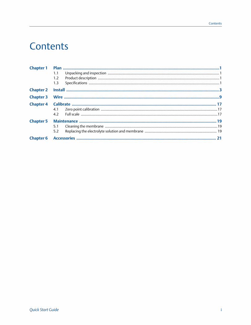
Rosemount 499ADO Sensor PartsFigure 1-1:
A. Membrane retainerB. Membrane assemblyC. O-ringD. CathodeE. Electrolyte fill plug (wrap with pipe tape)F. Pressure equalizing portG. Sensor cable (integral cable shown)
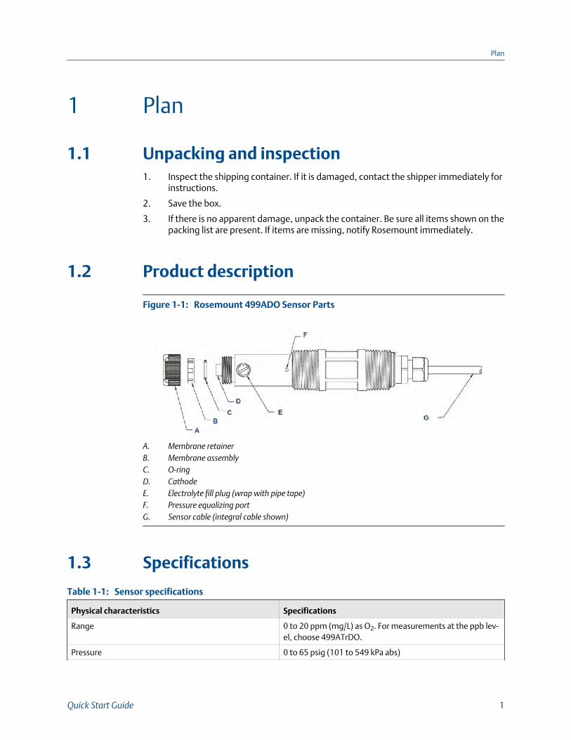
1.3 Specifications
Sensor specificationsTable 1-1:
Physical characteristics Specifications
Range 0 to 20 ppm (mg/L) as O2. For measurements at the ppb lev-el, choose 499ATrDO.
Pressure 0 to 65 psig (101 to 549 kPa abs)
Plan
Quick Start Guide 1

Sensor specifications (continued)Table 1-1:
Physical characteristics Specifications
Temperature (operating) 0 to 50 °C (32 to 122 °F)
Process connection 1 in. MNPT
Wetted parts Noryl®(1), Viton, EPDM, Teflon® (TFE)(2), and silicone
Cathode Gold (not normally wetted)
Accuracy ±0.2 ppm at 77 °F (25 °C)
Repeatability ±0.05 ppm at 77 °F (25 °C)
Response time < 30 sec to 90% of final reading (0 to 2 ppm) at 25 °C (77 °F)
Electrolyte volume 25 mL (approx.)
Electrolyte life 4 to 6 months (approx.)
Cable length (standard integral cable) 25 ft (7.6 m)
Cable length (maximum) 300 ft (91 m)
Sample flow
Flow through 1 to 5 gpm (3.8 to 19 L/min)
Open channel 1 ft/sec (0.3 m/sec)
Low flow cell 2 to 5 gph (7.6 to 19 L/hr)
Agitation produced by bubbles in aeration basins usuallyprovides adequate flow.
Process connections 1 inch MNPT
Weight/shipping weight 1 lb/3 lb (0.5kg /1.5 kg)
(1) Noryl is a registered trademark of General Electric.
(2) Viton and Teflon are registered trademarks of E.I. duPoint de Nemours & Co.
Plan
2 Rosemount 499ADO

2 Install
Install the sensor in a flowing sample. Keep the sample flow as constant as possible at avalue within the following limits:
Sample flow unit Flow limits
Flow through 1 to 5 gpm (3.8 to 19 L/min)
Open channel 1 ft/sec (0.3 m/sec)
Low flow cell 2 to 5 gph (7.6 to 19 L/hr)
The Rosemount 499ADO sensor can be installed in ponds or basins. Use a pipe screwedinto the back-facing threads to protect the cable and keep liquid away from the back endof the sensor. The cable end of the sensor is not intended for submersion under liquid. See Figure 2-5. For additional mounting hardware, see product data sheet 71-HRMS.
Sensor OrientationFigure 2-1:
Install
Quick Start Guide 3

Flow through 1-1/2 in. TeeFigure 2-2:
Install
4 Rosemount 499ADO
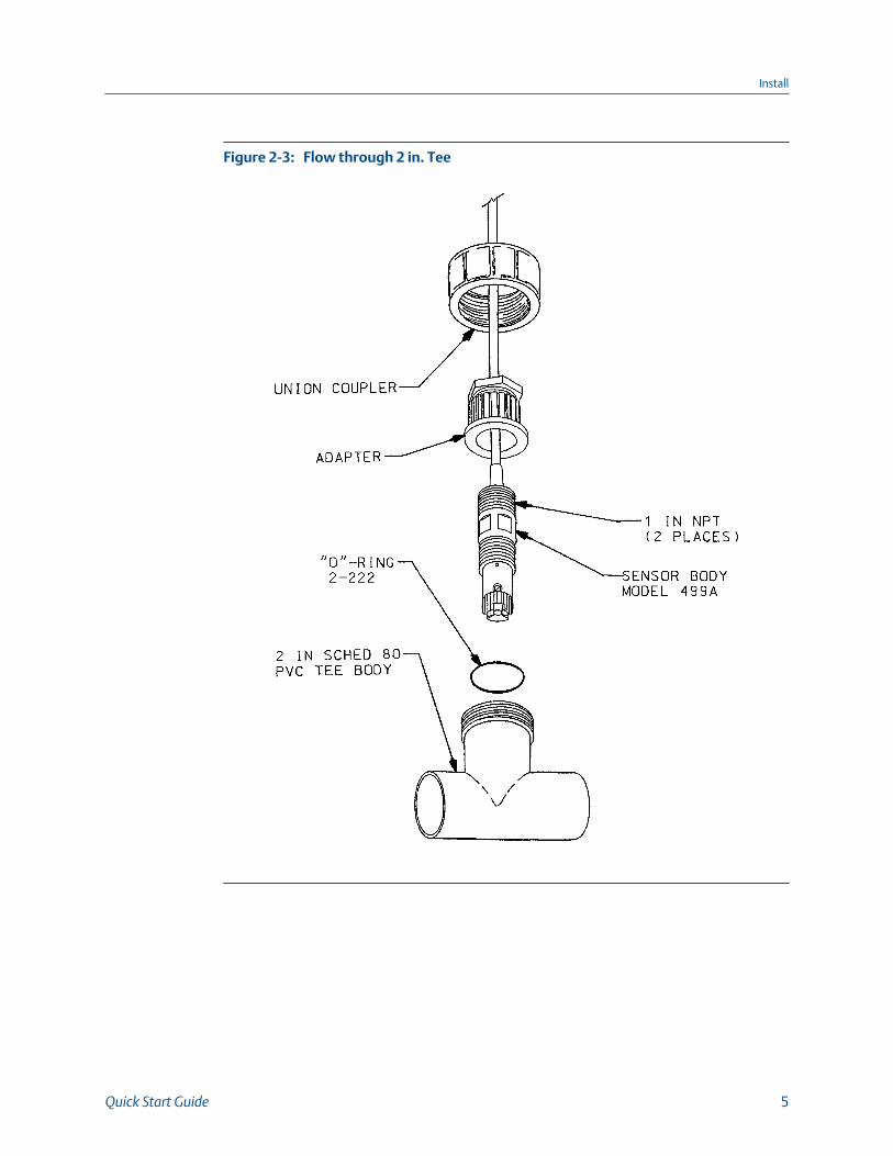
Flow through 2 in. TeeFigure 2-3:
Install
Quick Start Guide 5
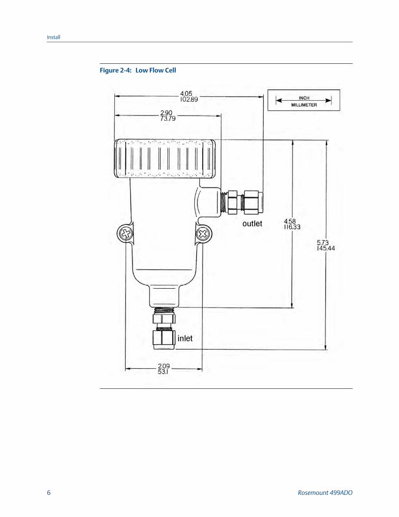
Low Flow CellFigure 2-4:
Install
6 Rosemount 499ADO
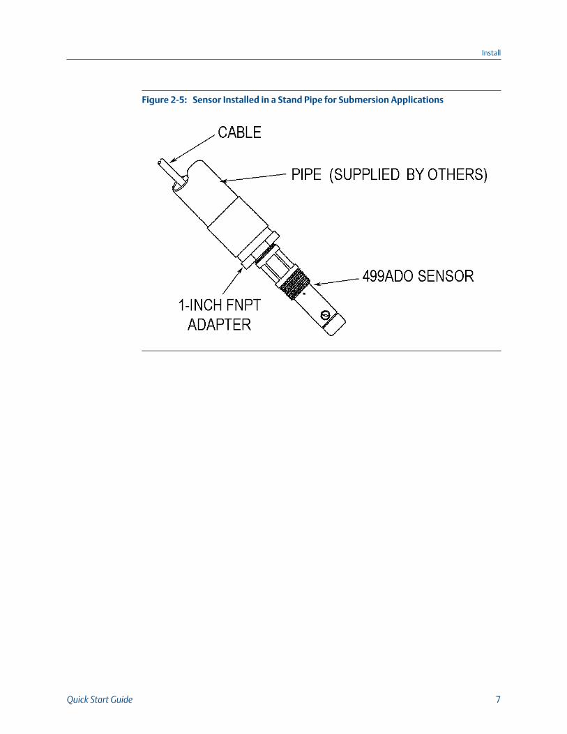
Sensor Installed in a Stand Pipe for Submersion ApplicationsFigure 2-5:
Install
Quick Start Guide 7

Install
8 Rosemount 499ADO
3 Wire
NOTICE
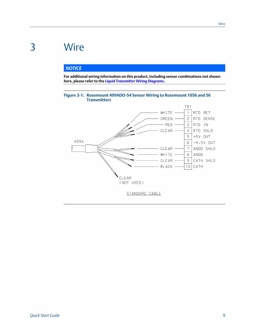
For additional wiring information on this product, including sensor combinations not shownhere, please refer to the Liquid Transmitter Wiring Diagrams.
Rosemount 499ADO-54 Sensor Wiring to Rosemount 1056 and 56Transmitters
Figure 3-1:
Wire
Quick Start Guide 9
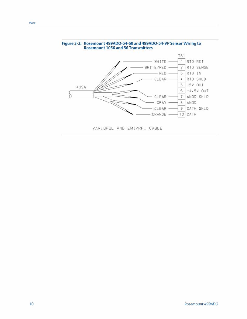
Rosemount 499ADO-54-60 and 499ADO-54-VP Sensor Wiring toRosemount 1056 and 56 Transmitters
Figure 3-2:
Wire
10 Rosemount 499ADO

Rosemount 499ADO-54 Sensor Wiring to Rosemount 5081 transmitterFigure 3-3:
Wire
Quick Start Guide 11

Rosemount 499ADO-54-60 Sensor Wiring to Rosemount 5081Transmitter
Figure 3-4:
Wire
12 Rosemount 499ADO
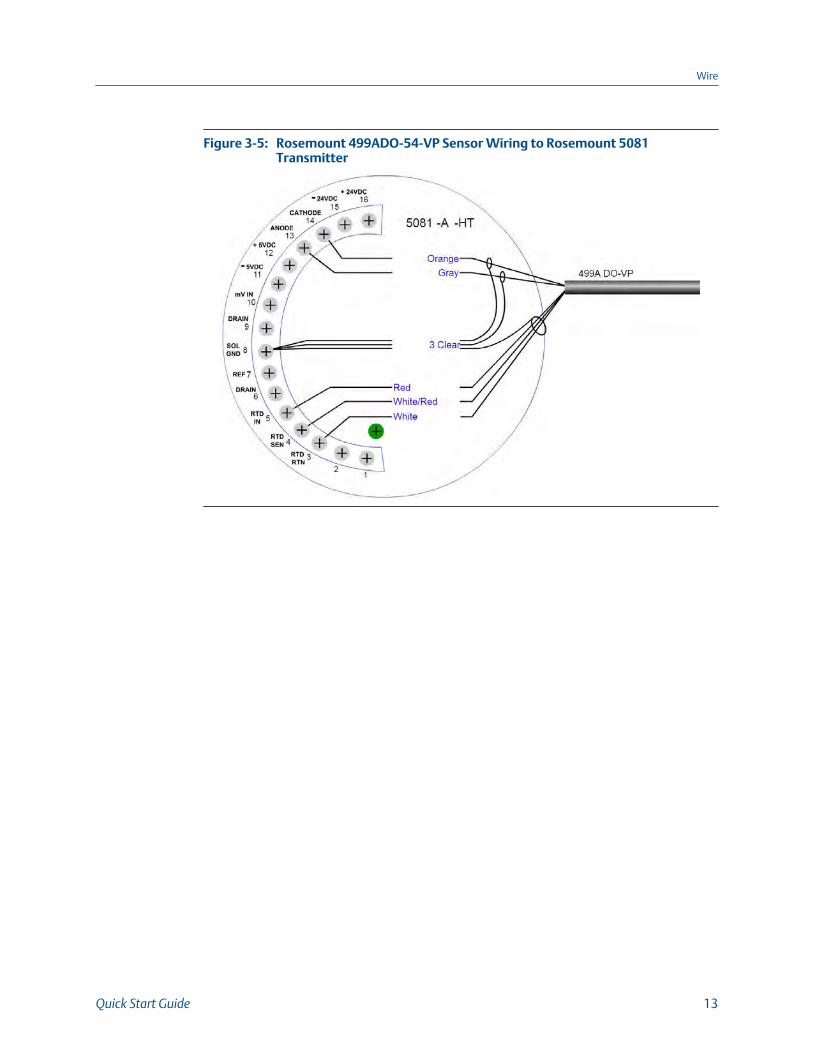
Rosemount 499ADO-54-VP Sensor Wiring to Rosemount 5081Transmitter
Figure 3-5:
Wire
Quick Start Guide 13

Rosemount 499ADO-54 Sensor Wiring to Rosemount 1066 TransmitterFigure 3-6:
Wire
14 Rosemount 499ADO

Rosemount 499ADO-54-60 Sensor Wiring to Rosemount 1066Transmitter
Figure 3-7:
Wire
Quick Start Guide 15

Rosemount 499ADO-54-VP Sensor Wiring to Rosemount 1066Transmitter
Figure 3-8:
Rosemount 499ADO Sensor Pin-out DiagramFigure 3-9:
When making a connection through a junction box (PN 23550-00), wire point-to-point.
NOTICE
Use a wire nut and pigtail (included) when connecting several wires to the same terminal.
Wire
16 Rosemount 499ADO

4 Calibrate
4.1 Zero point calibrationEven in the absence of oxygen, the Rosemount 499ADO sensor generates a small signalcalled the zero current. Failing to correct for the zero current can introduce a bias,particularly if the oxygen concentration is small (<1 ppm). Zero the sensor when it is firstplaced in service and every time the fill solution is changed.To zero the sensor:
Procedure
1. Pour a cup of deionized or bottled water.
2. Add a teaspoon of sodium sulfite to the water.
3. Place the sensor in the water.
4. Wait until the sensor current has reached a stable low value (at least two hours).
5. Follow the transmitter prompts for zeroing the sensor.
NoteRefer to the manual for the transmitter you are using (56, 1056, 5081, or 1066).
The zero current should be <200 nA.
4.2 Full scaleThe Rosemount 499ADO sensor is best calibrated by exposing the sensor to water-saturated air.
1. Pour a small amount of water into a cup.
2. Suspend the sensor, keeping the membrane dry, about 1/4 in. (6 mm) above thesurface of the water.
3. Once readings are stable, follow the analyzer prompts to complete the calibration.
The analyzer automatically calculates the equilibrium solubility of atmosphericoxygen in water under the prevailing temperature and barometric pressure.
4. After calibration, go to the Diagnostics menu and check the sensitivity.
The sensitivity should be between 1,800 and 3,000 nA/ppm.
For more information, refer to the transmitter manual.
Calibrate
Quick Start Guide 17

Calibrate
18 Rosemount 499ADO

5 Maintenance
Periodic maintenance and cleaning are required for best performance of the sensor.Generally, the membrane and fill solution should be replaced every four to six months.Sensors installed in harsh or dirty environments require more frequent maintenance. Theoptimum maintenance frequency is best determined by experience.
WARNING!
PRESSURIZED SPRAY INJURYBefore removing the sensor, be absolutely certain that the process pressure is reduced to0 psig and the process temperature is lowered to a safe level!
5.1 Cleaning the membraneKeep the membrane and sensor tip clean and free from dirt. Clean the membrane withwater sprayed from a wash bottle. Use a soft tissue to gently wipe the membrane.
5.2 Replacing the electrolyte solution andmembrane
WARNING!
HARMFUL SUBSTANCEFill solution may cause irritation. May be harmful if swallowed. Read and follow manual.
Procedure
1. Unscrew the membrane retainer.
2. Remove the membrane assembly and O-ring.
See Figure 1-1.
3. Hold the sensor over a container with the cathode pointing down.
4. Remove the fill plug.
5. Allow the electrolyte solution to drain out.
6. Inspect the cathode.
a. If it is tarnished, clean it by gently rubbing in the direction of the existingscratches (do not use a circular motion) with 400-600 grit silicon carbidefinishing paper.
b. Rinse thoroughly with water.
7. Remove the old pipe tape from the plug.
Maintenance
Quick Start Guide 19

8. Wrap the plug with one or two turns of pipe tape.
9. Prepare a new membrane.
a. Hold the membrane assembly with the cup formed by the membrane andmembrane holder pointing up.
b. Fill the cup with electrolyte solution.
c. Leave the membrane assembly filled with electrolyte solution and set it aside.
10. Hold the sensor at about a 45° angle with the cathode end pointing up.
11. Add electrolyte solution through the fill hole until the liquid overflows.
12. Tap the sensor near the threads to release trapped air bubbles.
13. Add more electrolyte solution if necessary.
14. Place the fill plug in the electrolyte port and begin screwing it in.
15. After several threads have engaged, rotate the sensor so that the cathode ispointing up and continue tightening the fill plug.
Do not overtighten.
16. Place a new O-ring in the groove around the cathode post.
17. Cover the holes at the base of the cathode stem with several drops of electrolytesolution.
18. Insert a small blunt probe, like a toothpick with the end cut off, through the pressureequalizing port.
See Figure 1-1.
CAUTION!EQUIPMENT DAMAGE
Do not use a sharp probe. It will puncture the bladder and destroy the sensor.
19. Gently press the probe against the bladder several times to force liquid through theholes at the base of the cathode stem. Keep pressing the bladder until no air bubblescan be seen leaving the holes. Be sure the holes remain covered with electrolytesolution.
20. Place a drop of electrolyte solution on the cathode; then place the membraneassembly over the cathode.
21. Screw the membrane retainer in place.
The sensor may require several hours operating at the polarizing voltage toequilibrate after the electrolyte solution has been replenished.
Maintenance
20 Rosemount 499ADO
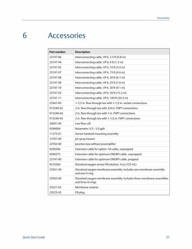
6 Accessories
Part number Description
23747-06 Interconnecting cable, VP 6, 2.5 ft (0.8 m)
23747-04 Interconnecting cable, VP 6, 4 ft (1.2 m)
23747-02 Interconnecting cable, VP 6, 10 ft (3.0 m)
23747-07 Interconnecting cable, VP 6, 15 ft (4.6 m)
23747-08 Interconnecting cable, VP 6, 20 ft (6.1 m)
23747-09 Interconnecting cable, VP 6, 25 ft (7.6 m)
23747-10 Interconnecting cable, VP 6, 30 ft (9.1 m)
23747-03 Interconnecting cable, VP 6, 50 ft (15.2 m)
23747-11 Interconnecting cable, VP 6, 100 ft (30.5 m)
23567-00 1-1/2 in. flow through tee with 1-1/2 in. socket connections
915240-03 2 in. flow through tee with 3/4 in. FNPT connections
915240-04 2 in. flow through tee with 1 in. FNPT connections
915240-05 2 in. flow through tee with 1-1/2 in. FNPT connections
24091-00 Low flow cell
9390004 Rotameter: 0.5 - 5.0 gph
11275-01 Sensor handrail mounting assembly
12707-00 Jet spray cleaner
22550-00 Junction box without preamplifier
9200266 Extension cable for option -54 cable, unprepped
9200275 Extension cable for optimum EMI/RFI cable, unprepped
23747-00 Extension cable for optimum EMI/RFI cable, prepped
9210264 Dissolved oxygen sensor fill solution, 4 oz (125 mL)
23501-00 Dissolved oxygen membrane assembly: includes one membrane assemblyand one O-ring
23502-00 Dissolved oxygen membrane assembly: includes three membrane assembliesand three O-rings
33521-02 Membrane retainer
33523-03 Fill plug
Accessories
Quick Start Guide 21
LIQ-QSG-499ADO
Rev K
2017
www.Emerson.com/RosemountLiquidAnalysisEmerson Automation Solutions8200 Market BlvdChanhassen, MN 55317Toll Free +1 800 999 9307F +1 952 949 [email protected]/RosemountLiquidAnalysis
EUROPEEmerson Automation SolutionsNeuhofstrasse 19a P.O. Box 1046CH-6340 BaarSwitzerlandT + 41 (0) 41 768 6111F + 41 (0) 41 768 [email protected]/RosemountLiquidAnalysis
MIDDLE EAST AND AFRICAEmerson Automation SolutionsEmerson FZEJebel Ali Free ZoneDubai, United Arab Emirates, P.O. Box 17033T +971 4 811 8100F +971 4 886 [email protected]/RosemountLiquidAnalysis
ASIA-PACIFICEmerson Automation Solutions1 Pandan CrescentSingapore 128461SingaporeT +65 777 8211F +65 777 [email protected]/RosemountLiquidAnalysis
©2017 Emerson Automation Solutions. All rights reserved.
The Emerson logo is a trademark and service mark of EmersonElectric Co. Rosemount is a mark of one of the Emerson family ofcompanies. All other marks are the property of their respectiveowners. The contents of this publication are presented forinformation purposes only, and while effort has been made toensure their accuracy, they are not to be construed as warranties orguarantees, expressed or implied, regarding the products orservices described herein or their use or applicability. All sales aregoverned by our terms and conditions, which are available onrequest. We reserve the right to modify or improve the designs orspecifications of our products at any time without notice.