Embed Size (px)
Citation preview
Quick Start Guide
ICM/ICAD Motorized Valves Installation, Programming, and Troubleshooting
© Danfoss | DCS (MWA) | 2016.07 DKRCI.EI.HT0.B3.22 | 520H4763 | 1
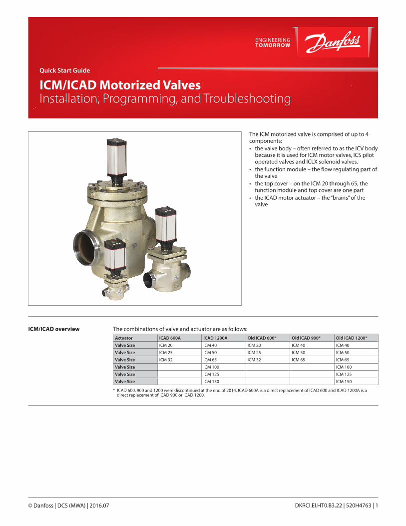
The ICM motorized valve is comprised of up to 4 components:• the valve body – often referred to as the ICV body
because it is used for ICM motor valves, ICS pilot operated valves and ICLX solenoid valves.
• the function module – the flow regulating part of the valve
• the top cover – on the ICM 20 through 65, the function module and top cover are one part
• the ICAD motor actuator – the “brains” of the valve
Actuator ICAD 600A ICAD 1200A Old ICAD 600* Old ICAD 900* Old ICAD 1200*
Valve Size ICM 20 ICM 40 ICM 20 ICM 40 ICM 40
Valve Size ICM 25 ICM 50 ICM 25 ICM 50 ICM 50
Valve Size ICM 32 ICM 65 ICM 32 ICM 65 ICM 65
Valve Size ICM 100 ICM 100
Valve Size ICM 125 ICM 125
Valve Size ICM 150 ICM 150
ICM/ICAD overview The combinations of valve and actuator are as follows:
* ICAD 600, 900 and 1200 were discontinued at the end of 2014. ICAD 600A is a direct replacement of ICAD 600 and ICAD 1200A is a direct replacement of ICAD 900 or ICAD 1200.
Quick Start Guide | ICM/ICAD Motorized Valves - Installation, Programming, and Troubleshooting
© Danfoss | DCS (MWA) | 2016.07 DKRCI.EI.HT0.B3.22 | 520H4763 | 2
Contents Page
ICM/ICAD overview . . . . . . . . . . . . . . . . . . . . . . . . . . . . . . . . . . . . . . . . . . . . . . . . . . . . . . . . . . . . . . . . . . . . . . . . . . . . . . . . . . . . . 1
Identifying ICM sizes . . . . . . . . . . . . . . . . . . . . . . . . . . . . . . . . . . . . . . . . . . . . . . . . . . . . . . . . . . . . . . . . . . . . . . . . . . . . . . . . . . . . 3
1st and 2nd generation ICAD differences . . . . . . . . . . . . . . . . . . . . . . . . . . . . . . . . . . . . . . . . . . . . . . . . . . . . . . . . . . . . . . . . . . 4Installation . . . . . . . . . . . . . . . . . . . . . . . . . . . . . . . . . . . . . . . . . . . . . . . . . . . . . . . . . . . . . . . . . . . . . . . . . . . . . . . . . . . . . . . . . . . . . 5Wiring the ICAD actuator . . . . . . . . . . . . . . . . . . . . . . . . . . . . . . . . . . . . . . . . . . . . . . . . . . . . . . . . . . . . . . . . . . . . . . . . . . . . . . . 7Electrical data . . . . . . . . . . . . . . . . . . . . . . . . . . . . . . . . . . . . . . . . . . . . . . . . . . . . . . . . . . . . . . . . . . . . . . . . . . . . . . . . . . . . . . . . . . 7ICAD Programming . . . . . . . . . . . . . . . . . . . . . . . . . . . . . . . . . . . . . . . . . . . . . . . . . . . . . . . . . . . . . . . . . . . . . . . . . . . . . . . . . . . .11Pre-start up checklist . . . . . . . . . . . . . . . . . . . . . . . . . . . . . . . . . . . . . . . . . . . . . . . . . . . . . . . . . . . . . . . . . . . . . . . . . . . . . . . . . .13Troubleshooting
Overview . . . . . . . . . . . . . . . . . . . . . . . . . . . . . . . . . . . . . . . . . . . . . . . . . . . . . . . . . . . . . . . . . . . . . . . . . . . . . . . . . . . . . . . . . .14Service parameters . . . . . . . . . . . . . . . . . . . . . . . . . . . . . . . . . . . . . . . . . . . . . . . . . . . . . . . . . . . . . . . . . . . . . . . . . . . . . . . .14Alarms. . . . . . . . . . . . . . . . . . . . . . . . . . . . . . . . . . . . . . . . . . . . . . . . . . . . . . . . . . . . . . . . . . . . . . . . . . . . . . . . . . . . . . . . . . . . .14Tips . . . . . . . . . . . . . . . . . . . . . . . . . . . . . . . . . . . . . . . . . . . . . . . . . . . . . . . . . . . . . . . . . . . . . . . . . . . . . . . . . . . . . . . . . . . . . . .15Frequently asked questions . . . . . . . . . . . . . . . . . . . . . . . . . . . . . . . . . . . . . . . . . . . . . . . . . . . . . . . . . . . . . . . . . . . . . . . .16
Quick Start Guide | ICM/ICAD Motorized Valves - Installation, Programming, and Troubleshooting
© Danfoss | DCS (MWA) | 2016.07 DKRCI.EI.HT0.B3.22 | 520H4763 | 3
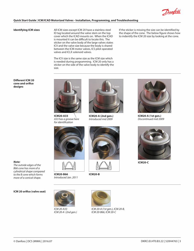
Different ICM 20 cone and orifice designs
ICM20-A33A33 has a groove here for identification
ICM20-A (2nd gen.)Introduced mid 2009
ICM20-A (1st gen.)Discontinued mid 2009
ICM20-C
ICM 20 orifice (valve seat)
ICM 20-A33ICM 20-A (2nd gen.)
ICM 20-A (1st gen.), ICM 20-B, ICM 20-B66, ICM 20-C
7 mm 5 mm
ICM20-B66Introduced Jan. 2011
ICM20-B
Note: The outside edges of the B66 cone has more of a cylindrical shape compared to the B cone which forms more of a conical shape.
Identifying ICM sizes All ICM sizes except ICM 20 have a stainless steel ID tag located around the valve stem on the top cover which the ICAD mounts on. When the ICAD is mounted it can be difficult to locate this. The sticker on the valve body of the large valves states ICV and the valve size because the body is shared between the ICM motor valves, ICS pilot operated valves and ICLX solenoid valves.
The ICV size is the same size as the ICM size which is needed during programming. ICM 20 only has a sticker on the side of the valve body to identify the size.
If the sticker is missing the size can be identified by the shape of the cone. The below figure shows how to indentify the ICM 20 size by looking at the cone.
Quick Start Guide | ICM/ICAD Motorized Valves - Installation, Programming, and Troubleshooting
© Danfoss | DCS (MWA) | 2016.07 DKRCI.EI.HT0.B3.22 | 520H4763 | 4
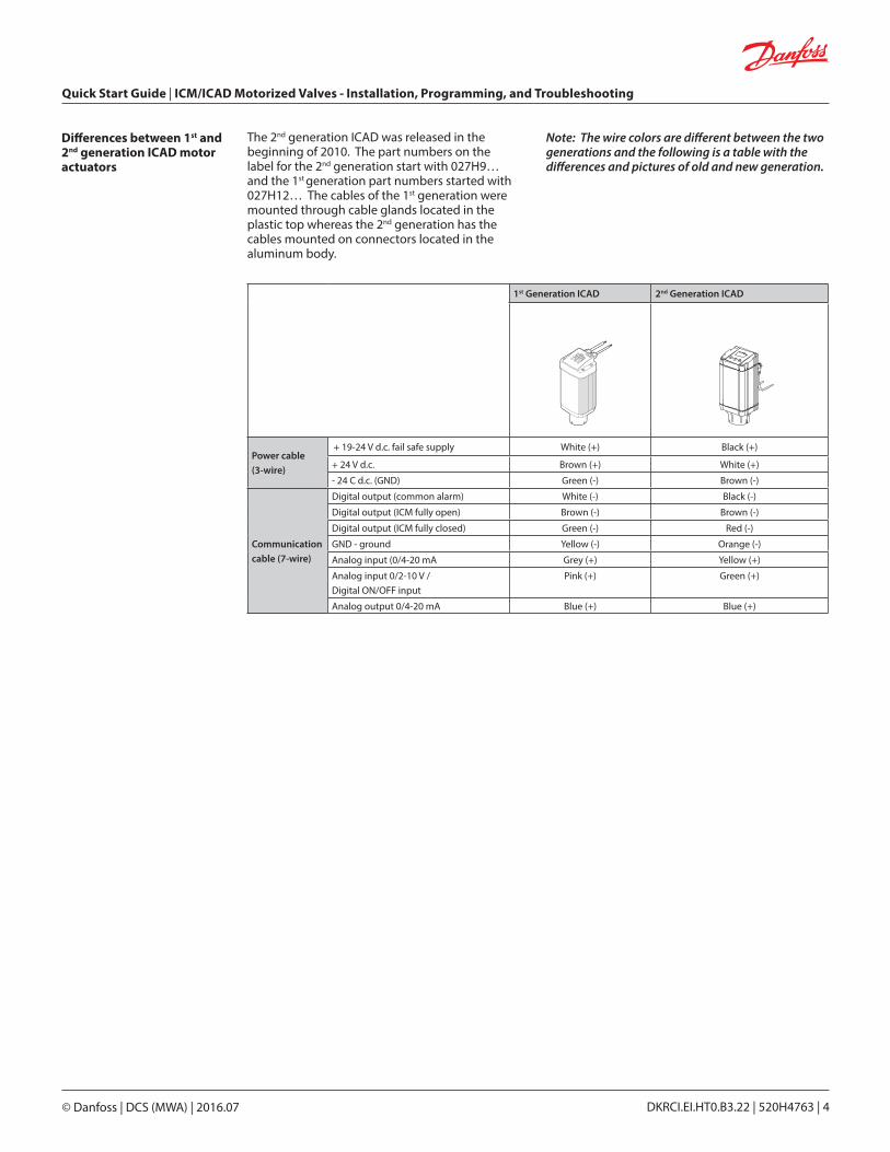
Differences between 1st and 2nd generation ICAD motor actuators
The 2nd generation ICAD was released in the beginning of 2010. The part numbers on the label for the 2nd generation start with 027H9… and the 1st generation part numbers started with 027H12… The cables of the 1st generation were mounted through cable glands located in the plastic top whereas the 2nd generation has the cables mounted on connectors located in the aluminum body.
Note: The wire colors are different between the two generations and the following is a table with the differences and pictures of old and new generation.
1st Generation ICAD 2nd Generation ICAD
Power cable (3-wire)
+ 19-24 V d.c. fail safe supply White (+) Black (+)
+ 24 V d.c. Brown (+) White (+)
- 24 C d.c. (GND) Green (-) Brown (-)
Communication cable (7-wire)
Digital output (common alarm) White (-) Black (-)
Digital output (ICM fully open) Brown (-) Brown (-)
Digital output (ICM fully closed) Green (-) Red (-)
GND - ground Yellow (-) Orange (-)
Analog input (0/4-20 mA Grey (+) Yellow (+)
Analog input 0/2-10 V / Digital ON/OFF input
Pink (+) Green (+)
Analog output 0/4-20 mA Blue (+) Blue (+)
Quick Start Guide | ICM/ICAD Motorized Valves - Installation, Programming, and Troubleshooting
© Danfoss | DCS (MWA) | 2016.07 DKRCI.EI.HT0.B3.22 | 520H4763 | 5
Installation
2a
2b
4a
2c
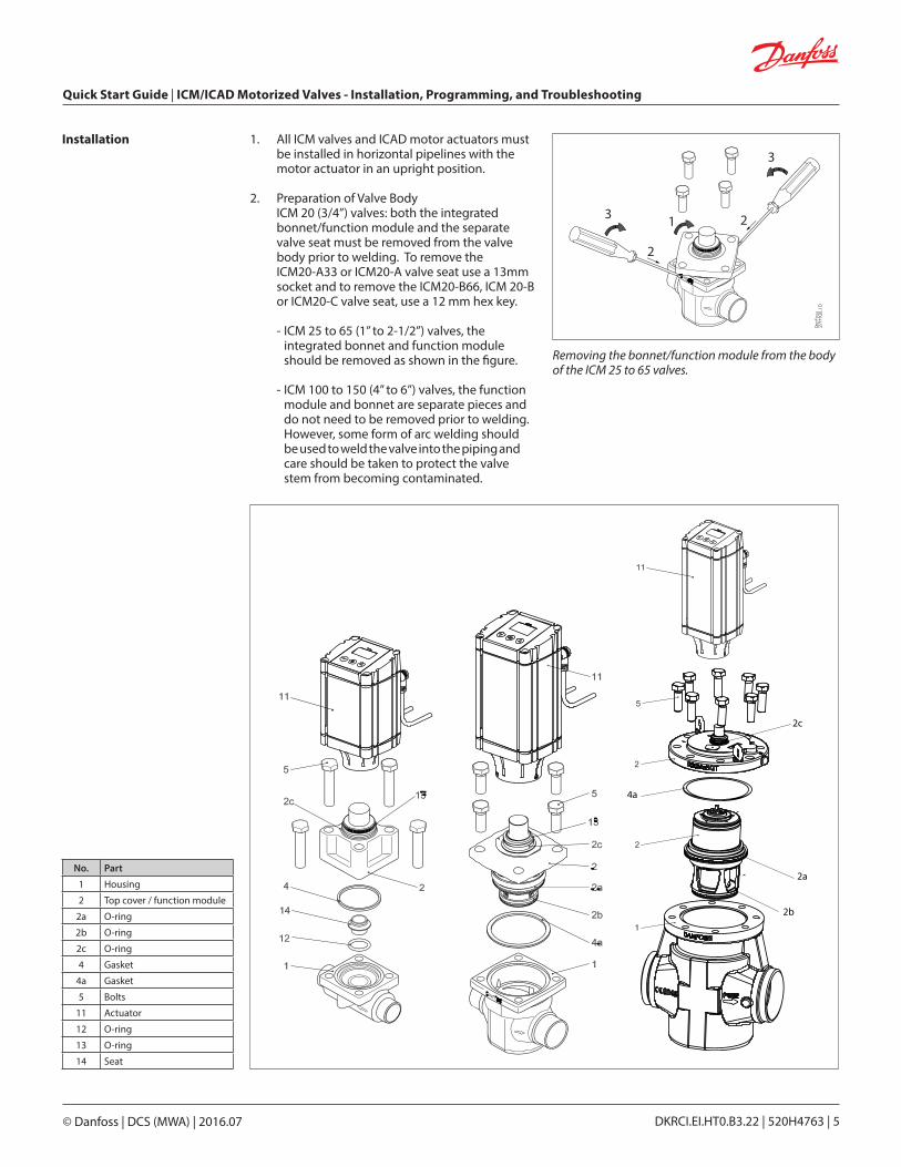
1. All ICM valves and ICAD motor actuators must be installed in horizontal pipelines with the motor actuator in an upright position.
2. Preparation of Valve Body ICM 20 (3/4”) valves: both the integrated bonnet/function module and the separate valve seat must be removed from the valve body prior to welding. To remove the ICM20-A33 or ICM20-A valve seat use a 13mm socket and to remove the ICM20-B66, ICM 20-B or ICM20-C valve seat, use a 12 mm hex key. - ICM 25 to 65 (1” to 2-1/2”) valves, the integrated bonnet and function module should be removed as shown in the figure. - ICM 100 to 150 (4” to 6”) valves, the function module and bonnet are separate pieces and do not need to be removed prior to welding. However, some form of arc welding should be used to weld the valve into the piping and care should be taken to protect the valve stem from becoming contaminated.
3
3 1
2
2
No. Part
1 Housing
2 Top cover / function module
2a O-ring
2b O-ring
2c O-ring
4 Gasket
4a Gasket
5 Bolts
11 Actuator
12 O-ring
13 O-ring
14 Seat
Removing the bonnet/function module from the body of the ICM 25 to 65 valves.
Quick Start Guide | ICM/ICAD Motorized Valves - Installation, Programming, and Troubleshooting
© Danfoss | DCS (MWA) | 2016.07 DKRCI.EI.HT0.B3.22 | 520H4763 | 6
Care should be taken to protect the ICM function module when it is removed and stored during installation of valve body. 3. Weld the valve body in line making sure that the arrow on the valve body is pointing in the direction of flow. - For ICM 20 through 65, make sure that all debris is removed from valve body before bonnet/ function module is re-installed. - For the ICM 20, make sure that the removable orifice seat is re-installed in the valve body with the small o-ring between the orifice seat and the body. Use a 13mm socket to tighten the ICM20-A33 or ICM20-A valve seat to a torque of 6.5 ft-lbs (9 N-m). Use a 12 mm hex key to tighten the ICM 20-B66, ICM20-B or ICM20-C valve seat to a torque of 1.5 ft-lbs (2 Nm). DO NOT OVERTIGHTEN THE REMOVABLE SEAT. Make sure that the bonnet gasket is installed and in good condition. - For the ICM 25 through ICM 65, check that the two o-rings are installed on the function module and that the gasket located on the top of the valve body is installed and all are in good condition. A light coating of refrigerant oil on the bonnet o-rings and the cover gasket will facilitate assembly of the valve.
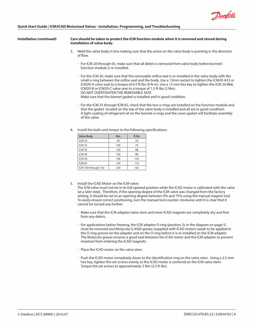
4. Install the bolts and torque to the following specifications:
5. Install the ICAD Motor on the ICM valve: The ICM valve must not be in its full opened position while the ICAD motor is calibrated with the valve (at a later step). Therefore, if the opening degree of the ICM valve was changed from the factory setting, it should be set to an opening degree between 0% and 75% using the manual magnet tool. To easily ensure correct positioning, turn the manual tool counter-clockwise until it is clear that it cannot be turned any further. - Make sure that the ICM adapter/valve stem and inner ICAD magnets are completely dry and free from any debris. - For applications below freezing, the ICM adapter O-ring (position 2c in the diagram on page 5) must be removed and Molycote G 4500 grease (supplied with ICAD motor) needs to be applied in the O-ring groove on the adapter and on the O-ring before it is re-installed on the ICM adapter. The Molycote grease ensures a good seal between the ICAD motor and the ICM adapter to prevent moisture from entering the ICAD magnets. - Place the ICAD motor on the valve stem. - Push the ICAD motor completely down to the identification ring on the valve stem. Using a 2.5 mm hex key, tighten the set screws evenly so the ICAD motor is centered on the ICM valve stem. Torque the set screws to approximately 3 Nm (2.5 ft-lbs).
Installation (continued)
Valve Body Nm ft lbs
ICM 20 40 29
ICM 25 100 74
ICM 32 120 88
ICM 40 120 88
ICM 50 140 103
ICM 65 150 110
ICM 100 through 150 220 162
Quick Start Guide | ICM/ICAD Motorized Valves - Installation, Programming, and Troubleshooting
© Danfoss | DCS (MWA) | 2016.07 DKRCI.EI.HT0.B3.22 | 520H4763 | 7
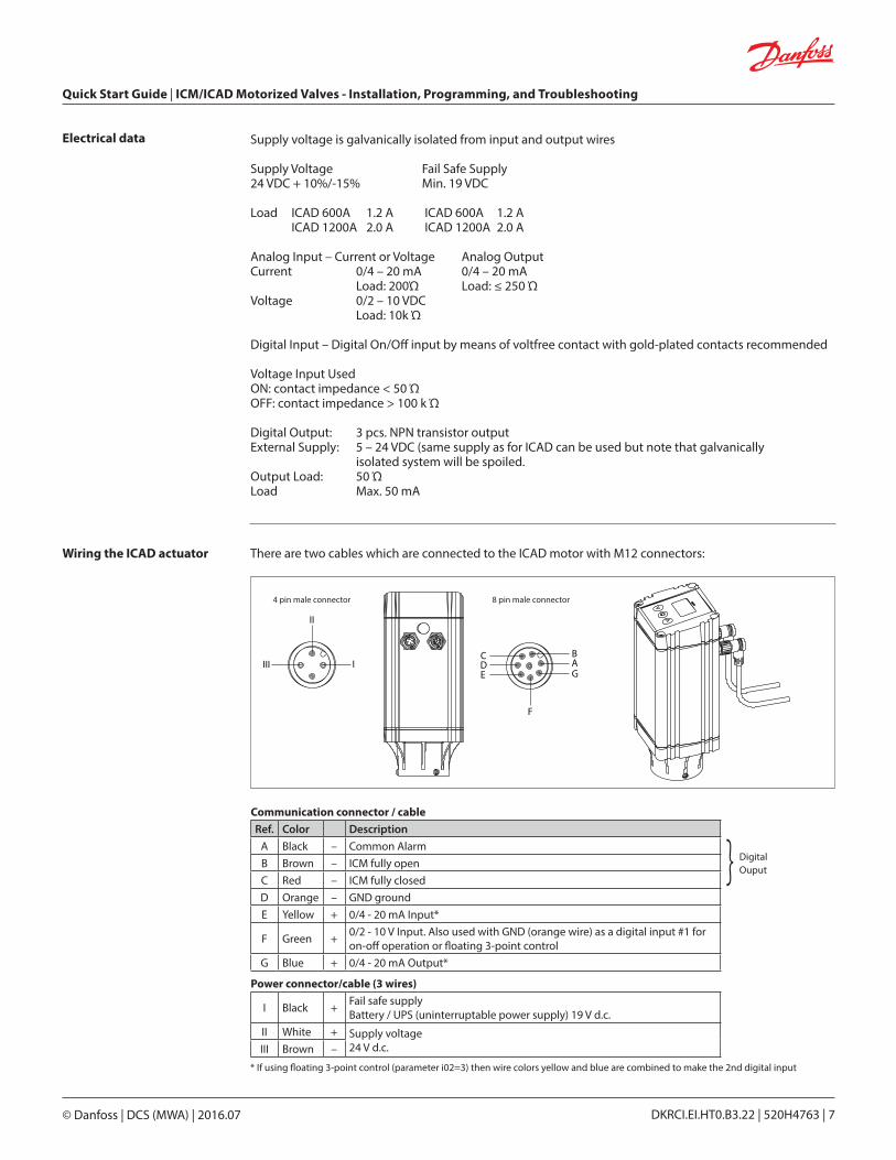
Wiring the ICAD actuator There are two cables which are connected to the ICAD motor with M12 connectors:
Supply voltage is galvanically isolated from input and output wires
Supply Voltage Fail Safe Supply24 VDC + 10%/-15% Min. 19 VDC Load ICAD 600A 1.2 A ICAD 600A 1.2 A ICAD 1200A 2.0 A ICAD 1200A 2.0 A
Analog Input – Current or Voltage Analog OutputCurrent 0/4 – 20 mA 0/4 – 20 mA Load: 200Ώ Load: ≤ 250 ΏVoltage 0/2 – 10 VDC Load: 10k Ώ
Digital Input – Digital On/Off input by means of voltfree contact with gold-plated contacts recommended
Voltage Input UsedON: contact impedance < 50 ΏOFF: contact impedance > 100 k Ώ
Digital Output: 3 pcs. NPN transistor outputExternal Supply: 5 – 24 VDC (same supply as for ICAD can be used but note that galvanically isolated system will be spoiled.Output Load: 50 ΏLoad Max. 50 mA
Electrical data
Communication connector / cableRef. Color Description
A Black – Common AlarmB Brown – ICM fully openC Red – ICM fully closedD Orange – GND groundE Yellow + 0/4 - 20 mA Input*
F Green + 0/2 - 10 V Input. Also used with GND (orange wire) as a digital input #1 for on-off operation or floating 3-point control
G Blue + 0/4 - 20 mA Output*
Power connector/cable (3 wires)
I Black + Fail safe supplyBattery / UPS (uninterruptable power supply) 19 V d.c.
II White + Supply voltage24 V d.c.III Brown –
} Digital Ouput
III I
II
CDE
BAG
F
4 pin male connector 8 pin male connector
* If using floating 3-point control (parameter i02=3) then wire colors yellow and blue are combined to make the 2nd digital input
Quick Start Guide | ICM/ICAD Motorized Valves - Installation, Programming, and Troubleshooting
© Danfoss | DCS (MWA) | 2016.07 DKRCI.EI.HT0.B3.22 | 520H4763 | 8
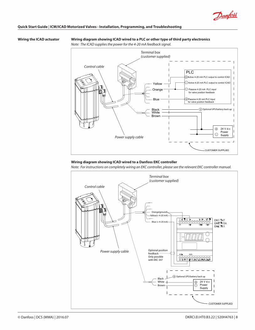
Wiring the ICAD actuator Wiring diagram showing ICAD wired to a PLC or other type of third party electronicsNote: The ICAD supplies the power for the 4-20 mA feedback signal.
WhiteBrown
Yellow
Orange
PLC
Blue
Active 4-20 mA PLC output to control ICAD
Passive 4-20 mA PLC input for valve position feedback
Passive 4-20 mA PLC input for valve position feedback
Black Optional UPS/battery back up
Active 4-20 mA PLC output to control ICAD+
+
+
-
-
+
-Power supply cable
Control cable
Terminal box(customer supplied)
Wiring diagram showing ICAD wired to a Danfoss EKC controllerNote: For instructions on completely wiring an EKC controller, please see the relevant EKC controller manual.
Orange(ground)
Yellow
Blue (+ 4-20 mA)
WhiteBrown
Optional position feedbackOnly possible with EKC 347
24 V d.cPower Supply
(+ 4-20 mA)
Black
+-
Optional UPS/battery back up+
CUSTOMER SUPPLIED
Power supply cable
Control cable
Terminal box(customer supplied)
Quick Start Guide | ICM/ICAD Motorized Valves - Installation, Programming, and Troubleshooting
© Danfoss | DCS (MWA) | 2016.07 DKRCI.EI.HT0.B3.22 | 520H4763 | 9
AKS 4100/4100U
AKS 41
Connectionsupper level
DI1 - main switch4-20
mA
CANbus connectionto other EKE controllers
plug forremote display
ModBUS
4-20 mA
24 V DC
orange Optional ICAD/ICM Valve Position
Feedback
ICAD 2nd gen
blue
24 V AC
L
N
+
–
1
2 3
orangeICAD 2nd gen (2010 +)
yellow
brown
white
24 V
+15
V+
5 V+
COM
AI 5
AI 4
AI 3
AI 2
AI 1
COM
COM
DI 2
DI 1
COM
R120
CAN
HCA
N L
GN
D
R G
ND
D+
D-
COM
AO
1CAN RJ
24 V DC
1
15 16 17 18 19 20 21 22 23 24
2 3 4 5 6 7 8 9 10 11 12 13 14
Upper level
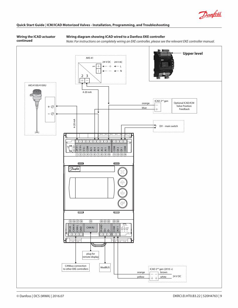
Wiring diagram showing ICAD wired to a Danfoss EKE controller Note: For instructions on completely wiring an EKE controller, please see the relevant EKE controller manual.
Wiring the ICAD actuator continued
Quick Start Guide | ICM/ICAD Motorized Valves - Installation, Programming, and Troubleshooting
© Danfoss | DCS (MWA) | 2016.07 DKRCI.EI.HT0.B3.22 | 520H4763 | 10
Wiring the ICAD actuator continued
CUSTOMER SUPPLIED
WhiteBrown
Green
Orange
Relay
Black Optional UPS/battery back up
+
24 V d.cPower Supply
+-
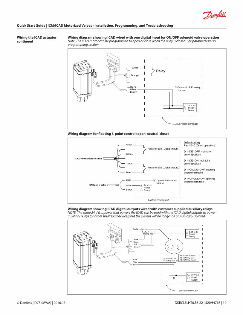
Wiring diagram showing ICAD wired with one digital input for ON/OFF solenoid valve operationNote: The ICAD motor can be programmed to open or close when the relay is closed. See parameter ¡09 in programming section.
CUSTOMER SUPPLIED
5-24 V d.cK 1 K 2 K 3
K 2K 1 K 3K 2K 1 K 3
K1 : Common AlarmK2 : ICM fully openK3 : ICM fully closed
Auxillary relays
BlackBrownRed
Orange
White
Brown
24 V d.cPower Supply
+-
Power Supply
+-
BlackOptional UPS/battery back up+
Wiring diagram showing ICAD digital outputs wired with customer supplied auxiliary relays NOTE: The same 24 V d.c. power that powers the ICAD can be used with the ICAD digital outputs to power auxiliary relays (or other small load devices) but the system will no longer be galvanically isolated.
White
Black
Brown
Green
Orange
Yellow
Blue
ICAD power cable
ICAD communication cable
Relay for DI1 (Digital Input1)
Relay for DI2 (Digital Input2)
Default settingPar. i13=0 (Direct operation)
DI1=DI2=OFF: maintains current position
DI1=DI2=ON: maintains current position
DI1=ON, DI2=OFF: opening degree increases
DI1=OFF, DI2=ON: opening degree decreases
+–
24 V d.cPower Supply
+ Optional UPS/batteryback up
Wiring diagram for floating 3-point control (open-neutral-close)
Customer supplied
Quick Start Guide | ICM/ICAD Motorized Valves - Installation, Programming, and Troubleshooting
© Danfoss | DCS (MWA) | 2016.07 DKRCI.EI.HT0.B3.22 | 520H4763 | 11
1. All ICAD actuators are digital stepper motors. As the control signal changes ICAD will electronically count steps up or down from its previous position. The ICAD 600A, ICAD 1200 and 1200A have an optical encoder which will actually measure the steps to recalibrate while operating if needed. In all cases, the ICAD actuators will recalibrate every time that power is cut and then reconnected. Recalibration is also accomplished when the valve is driven closed, the ICAD will take an extra closing step to make sure it is completely closed and start counting from 0 again.
2. The ICAD actuators can also be put into manual mode by using parameter ¡01. Once the parameter has been selected and the manual mode entered, the valve can be opened and closed independent of the control signal. When in the manual mode, the display screen will flash the opening degree and continue to flash until the parameter is restored to its normal operation setting.
3. The ICAD actuator can be controlled with an analog input for modulating control, 1 digital input for open/close solenoid function or with 2 digital inputs for floating 3-point control (open-neutral-close). The speed of the ICAD can be altered (see parameters ¡04 and ¡14).
4. The ICAD display will continuously display the ICM valve opening degree in % unless there is an alarm or the parameter list is being viewed. The display will also indicate Mod if being controlled by an analog input signal (modulating mode) or if being controlled by digital inputs the display will indicate Low, Med or High depending on the speed setting.
5. The ICAD actuator can be connected to a 24 V d.c. UPS (uninterruptable power supply) and can be programmed for a specific action in the event of a disruption to the normal power supply (see parameters ¡07, ¡08 and ¡12). Please note that the UPS provides a discrete short term action in the event of a power failure. It cannot be used for normal operation.
6. The ICAD actuator also has an inverse function (see parameter ¡13). This feature allows the valve to either open or close on a rising analog signal.
ICAD overview
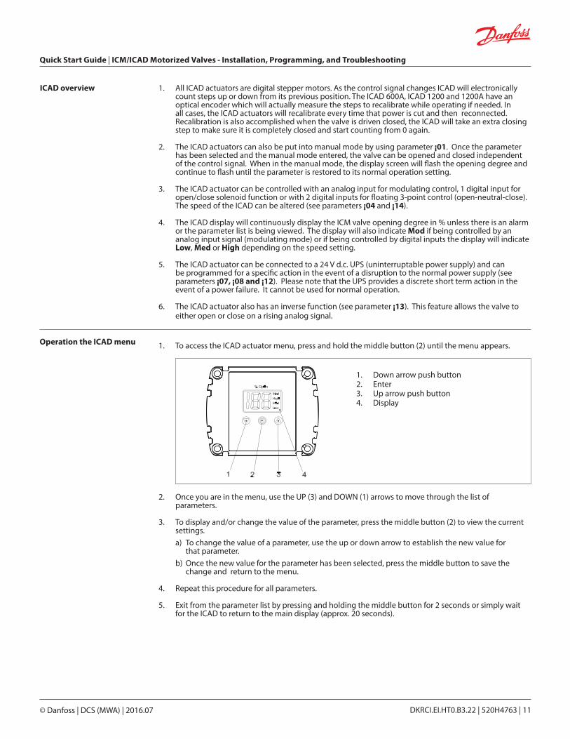
Operation the ICAD menu 1. To access the ICAD actuator menu, press and hold the middle button (2) until the menu appears.
2. Once you are in the menu, use the UP (3) and DOWN (1) arrows to move through the list of parameters.
3. To display and/or change the value of the parameter, press the middle button (2) to view the current settings. a) To change the value of a parameter, use the up or down arrow to establish the new value for that parameter. b) Once the new value for the parameter has been selected, press the middle button to save the change and return to the menu.
4. Repeat this procedure for all parameters.
5. Exit from the parameter list by pressing and holding the middle button for 2 seconds or simply wait for the ICAD to return to the main display (approx. 20 seconds).
1. Down arrow push button2. Enter3. Up arrow push button4. Display
Quick Start Guide | ICM/ICAD Motorized Valves - Installation, Programming, and Troubleshooting
© Danfoss | DCS (MWA) | 2016.07 DKRCI.EI.HT0.B3.22 | 520H4763 | 12
Programming the ICAD actuator
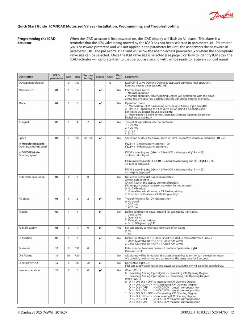
When the ICAD actuator is first powered on, the ICAD display will flash an A1 alarm. This alarm is a reminder that the ICM valve being moved by the ICAD has not been selected in parameter ¡26. Parameter ¡26 is password protected and will not appear in the parameter list until the user enters the password in parameter ¡10. The password is “11” and will allow the user to access parameter ¡26 where the appropriate valve size can be selected. Once the ICM valve size is selected (see page 3 on how to identify ICM size), the ICAD actuator will calibrate itself to that particular size and will then be ready to receive a control signal.
Description ICAD parameter Min Max Factory
Setting Stored Unit Pass word Comments
OD (Opening degree) - 0 100 % - ICM/ICMTS valve Opening Degree is displayed during normal operation. Running display value (see ¡01, ¡05).
Main Switch ¡01 1 2 1 - No Internal main switch 1: Normal operation 2: Manual operation. Valve Opening Degree will be flashing. With the down arrow and the up arrow push buttons the OD can be entered manually.
Mode ¡02 1 2 1 - No Operation mode 1: Modulating – ICM positioning according to Analog Input (see ¡03) 2: ON/OFF - operating the ICM valve like an ON/OFF solenoid valve controlled via Digital Input. See also ¡09.3: Neutralzone / 3 point control. Increase/Decrease Opening Degree by Digital Input. See fig. 9
AI signal ¡03 1 4 2 - No Type of AI signal from external controller 1: 0-20 mA 2: 4-20 mA 3: 0-10 V 4: 2-10 V
Speed
In Modulating Mode Opening/closing speed In ON/OFF Mode Opening speed
¡04 1 100 50/ 100 - No Speed can be decreased. Max. speed is 100 % - Not active in manual operation (¡01 = 2) If ¡26= 1 - 3 then factory setting =100 If ¡26= 4 - 9 then factory setting =50 If ICM is opening and (¡04 < = 33) or ICM is closing and (¡14 < = 33) => Low is displayed. If ICM is opening and (33 < If ¡04 < = 66) or ICM is closing and (33 < If ¡14 < = 66) => Med is displayed. If ICM is opening and (¡04 > = 67) or ICM is closing and (¡14 > = 67) => High is displayed"
Automatic calibration ¡05 0 2 0 - No Not active before ¡26 has been operated. Always auto reset to 0. CA will flash in the display during calibration, if Enter push button has been activated for two seconds 0: No Calibration 1: Normal forced calibration - CA flashing slowly 2: Extended calibration – CA flashing rapidly"
AO signal ¡06 0 2 2 - No Type of A0 signal for ICV valve position 0: No signal 1: 0-20 mA 2: 4-20 mA
Failsafe ¡07 1 4 1 - No Define condition at power cut and fail safe supply is installed. 1: Close valve 2: Open Valve 3: Maintain valve position 4: Go to OD given by ¡12"
Fail safe supply ¡08 0 1 0 Yes Fail safe supply connected and enable of A4 alarm: 0: No 1: Yes
DI function ¡09 1 2 1 No Define function when DI is ON (short circuited DI terminals) when ¡02 = 2 1: Open ICM valve (DI = OFF = > Close ICM valve) 2: Close ICM valve (DI = OFF = > Open ICM valve)
Password ¡10 0 199 0 - - Enter number to access password protected parameters: ¡26 Password = 11
Old Alarms ¡11 A1 A99 - - No Old alarms will be listed with the latest shown first. Alarm list can be reset by means of activating down arrow and up arrow at the same time for 2 seconds.
OD at power cut. ¡12 0 100 50 No Only active if ¡07 = 4 If fail safe supply is connected and power cut occurs, the ICM will go to the specified OD.
Inverse operation ¡13 0 1 0 No When ¡02 = 10: Increasing Analog Input signal => Increasing ICM Opening Degree 1: Increasing Analog Input signal => Decreasing ICM Opening Degree When ¡02 = 30: DI1 = ON, DI2 = OFF => Increasing ICM Opening Degree. DI1 = OFF, DI2 = ON => Decreasing ICM Opening Degree DI1 = DI2 = OFF => ICAD/ICM maintain current position DI1 = DI2 = ON => ICAD/ICM maintain current position1: DI1 = ON, DI2 = OFF => Decreasing ICM Opening Degree DI1 = OFF, DI2 = ON => Increasing ICM Opening Degree DI1 = DI2 = OFF => ICAD/ICM maintain current position DI1 = DI2 = ON => ICAD/ICM maintain current position
Quick Start Guide | ICM/ICAD Motorized Valves - Installation, Programming, and Troubleshooting
© Danfoss | DCS (MWA) | 2016.07 DKRCI.EI.HT0.B3.22 | 520H4763 | 13
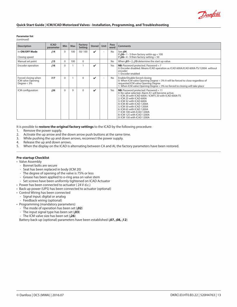
Description ICAD parameter Min Max Factory
Setting Stored Unit Pass word Comments
In ON/OFF Mode Closing speed
¡14 0 100 50/ 100 - No See ¡04. If ¡26= 1 - 3 then factory settin qg = 100 If ¡26= 4 - 9 then factory setting = 50
Manual set point ¡15 0 100 0 No When ¡01= 2, ¡15 determine the start up value.
Encoder operation ¡16 0 1 1 Yes NB: Password protected. Password = 7 0: Encoder disabled. Means ICAD operation as ICAD 600A/ICAD 600A-TS/1200A without encoder 1: Encoder enabled
Forced closing whenICM valve Opening Degree < 3%
i17 0 1 0 - No Enable/Disable forced closing0: When ICM valve Opening Degree < 3% it will be forced to close regardless of requested ICM valve Opening Degree1: When ICM valve Opening Degree < 3% no forced to closing will take place
ICM configuration ¡26 0 9 0 Yes NB: Password protected. Password = 11 0: No valve selected. Alarm A1 will become active. 1: ICM 20 with ICAD 600A / ICMTS 20 with ICAD 600A-TS2: ICM 25 with ICAD 600A3: ICM 32 with ICAD 600A4: ICM 40 with ICAD 1200A5: ICM 50 with ICAD 1200A6: ICM 65 with ICAD 1200A7: ICM 100 with ICAD 1200A8: ICM 125 with ICAD 1200A9: ICM 150 with ICAD 1200A
Parameter list (continued)
It is possible to restore the original factory settings to the ICAD by the following procedure:1. Remove the power supply.2. Activate the up arrow and the down arrow push buttons at the same time.3. While pushing the up and down arrows, reconnect the power supply.4. Release the up and down arrows.5. When the display on the ICAD is alternating between CA and AI, the factory parameters have been restored.
Pre-startup Checklist• Valve Assembly
- Bonnet bolts are secure - Seat has been replaced in body (ICM 20) - The degree of opening of the valve is 75% or less - Grease has been applied to o-ring area on valve stem - Set screws have been uniformly tightened on ICAD Actuator
• Power has been connected to actuator ( 24 V d.c.)• Back up power (UPS) has been connected to actuator (optional)• Control Wiring has been connected
- Signal input: digital or analog - Feedback wiring (optional)
• Programming (mandatory parameters) - The mode of operation has been set (¡02) - The input signal type has been set (¡03) - The ICM valve size has been set (¡26) Battery back-up (optional) parameters have been established (¡07, ¡08, ¡12)
Quick Start Guide | ICM/ICAD Motorized Valves - Installation, Programming, and Troubleshooting
© Danfoss | DCS (MWA) | 2016.07 DKRCI.EI.HT0.B3.22 | 520H4763 | 14
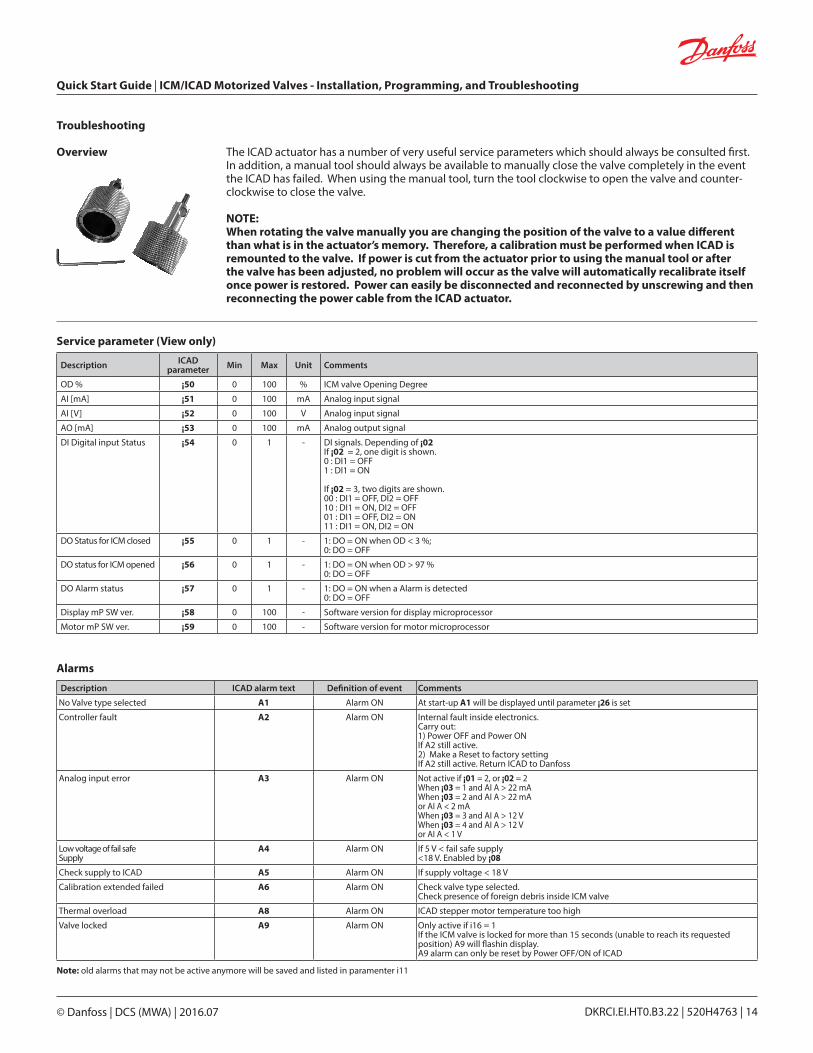
Troubleshooting
Overview The ICAD actuator has a number of very useful service parameters which should always be consulted first. In addition, a manual tool should always be available to manually close the valve completely in the event the ICAD has failed. When using the manual tool, turn the tool clockwise to open the valve and counter-clockwise to close the valve.
NOTE: When rotating the valve manually you are changing the position of the valve to a value different than what is in the actuator’s memory. Therefore, a calibration must be performed when ICAD is remounted to the valve. If power is cut from the actuator prior to using the manual tool or after the valve has been adjusted, no problem will occur as the valve will automatically recalibrate itself once power is restored. Power can easily be disconnected and reconnected by unscrewing and then reconnecting the power cable from the ICAD actuator.
Service parameter (View only)
Alarms
Description ICAD parameter Min Max Unit Comments
OD % ¡50 0 100 % ICM valve Opening Degree
AI [mA] ¡51 0 100 mA Analog input signal
AI [V] ¡52 0 100 V Analog input signal
AO [mA] ¡53 0 100 mA Analog output signal
DI Digital input Status ¡54 0 1 - DI signals. Depending of ¡02 If ¡02 = 2, one digit is shown. 0 : DI1 = OFF1 : DI1 = ON
If ¡02 = 3, two digits are shown. 00 : DI1 = OFF, DI2 = OFF 10 : DI1 = ON, DI2 = OFF 01 : DI1 = OFF, DI2 = ON 11 : DI1 = ON, DI2 = ON
DO Status for ICM closed ¡55 0 1 - 1: DO = ON when OD < 3 %; 0: DO = OFF
DO status for ICM opened ¡56 0 1 - 1: DO = ON when OD > 97 %0: DO = OFF
DO Alarm status ¡57 0 1 - 1: DO = ON when a Alarm is detected0: DO = OFF
Display mP SW ver. ¡58 0 100 - Software version for display microprocessor
Motor mP SW ver. ¡59 0 100 - Software version for motor microprocessor
Description ICAD alarm text Definition of event Comments
No Valve type selected A1 Alarm ON At start-up A1 will be displayed until parameter ¡26 is set
Controller fault A2 Alarm ON Internal fault inside electronics. Carry out:1) Power OFF and Power ON If A2 still active.2) Make a Reset to factory settingIf A2 still active. Return ICAD to Danfoss
Analog input error A3 Alarm ON Not active if ¡01 = 2, or ¡02 = 2When ¡03 = 1 and AI A > 22 mAWhen ¡03 = 2 and AI A > 22 mAor AI A < 2 mAWhen ¡03 = 3 and AI A > 12 VWhen ¡03 = 4 and AI A > 12 Vor AI A < 1 V
Low voltage of fail safe Supply
A4 Alarm ON If 5 V < fail safe supply<18 V. Enabled by ¡08
Check supply to ICAD A5 Alarm ON If supply voltage < 18 V
Calibration extended failed A6 Alarm ON Check valve type selected.Check presence of foreign debris inside ICM valve
Thermal overload A8 Alarm ON ICAD stepper motor temperature too high
Valve locked A9 Alarm ON Only active if i16 = 1If the ICM valve is locked for more than 15 seconds (unable to reach its requested position) A9 will flashin display.A9 alarm can only be reset by Power OFF/ON of ICAD
Note: old alarms that may not be active anymore will be saved and listed in paramenter i11
Quick Start Guide | ICM/ICAD Motorized Valves - Installation, Programming, and Troubleshooting
© Danfoss | DCS (MWA) | 2016.07 DKRCI.EI.HT0.B3.22 | 520H4763 | 15
Troubleshooting continued The alarms and service values work together to allow the user to quickly diagnose the source of operating issues. The most common alarms are:A1 The user has not selected the valve type. Each ICAD actuator is capable of driving several different valve sizes. Upon installation of the valve, it is mandatory that the user select the valve size from parameter ¡26.
A3 The control signal is out of the range of the selected values. The most common causes of this problem are:
1. Improper wiring2. Incorrect selection of control signal (parameter ¡03)3. The source of the control signal is not outputting the correct type of signal.
A9 The valve is locked, disconnect and remove motor. Use magnetic tool to slowly open/close the valve thru the full range. There should be at no point a sticking/tight spot. You may need to remove the valve bonnet/module to clean debris or replace the bonnet/module if it is damaged. If A9 alarm continues please contact Danfoss with application details.
Of course, there are numerous other alarm messages designed to protect the equipment and help to diagnose problems as pro-actively as possible. Most of these alarms are fairly self-explanatory.
The valve does not appear to close or stay closed completely.• The display shows 0% opening degree but the valve can be driven further closed with the manual
tool. Solution: Recalibrate the valve. In addition, if the manual tool has been used to open or close the valve, the valve should turn very easily. If there appears to be resistance in opening or closing the valve, replace the module.
• The display shows 0% opening degree and the valve cannot be driven closed any further with the manual tool. Solution: Pull the function module and check to ensure that there are 2 o-rings on the module for ICM 25 and larger. For size ICM 20, make sure valve seat is installed.
The valve does not appear to be moving to the correct position.• Check service value ¡51. This is the mA input from the control system. The degree of opening is
linearly proportional to the mA input. (For example, if 4-20 mA was chosen as the input range and the service value shows 12mA, the valve should be 50% open.) Solution: Check parameter ¡03 to make sure that the correct scale was selected.
• Compare service value ¡51 to the value reported to be the output from the control system. If necessary, measure the actual current into the ICAD. Solution: If the two values do not equate, check wiring, paying special attention to wire polarity. If measured mA does not equate to the stated controllers output, the problem is likely to be in the control system. If measured mA does not equate to the value seen in ¡51 and everything is wired properly, the problem is likely with the ICAD actuator.
• The ICAD was not mounted properly on the valve stem. Solution: Check to make sure that the ICAD set screws are evenly torqued around the base of the ICAD.
The valve does not appear to be opening fast enough or seems too fast• The speed of the ICM valves are preset at the factory:
• For ICM valves 20, 25, and 32, the preset speed is 100%• For ICM valves 40, 50, 65, 100, 125, and 150, the preset speed is 50%
Solution: Check parameter ¡04 to note the actual setting and adjust accordingly
The valve position feedback signal is not working with the customer supplied controller/PLC.• A power supply was installed in the 4-20mA/0-20 mA feedback loop. The ICAD motor actuator
supplies power for the 4-20mA/0-20 mA feedback loop. Solution: Remove any power source that may be supplied to the feedback loop.
• Wiring problem. Solution: Check the service value of ¡53 (the analog output signal) to see what the ICAD is outputting. If nothing is revealed, check the output wire (blue) with an ammeter to verify the actual output value.
• The feedback output signal was not turned on in parameter ¡06. Solution: Change this parameter to the appropriate signal.
Troubleshooting Tips
Quick Start Guide | ICM/ICAD Motorized Valves - Installation, Programming, and Troubleshooting
© Danfoss | DCS (MWA) | 2016.07 DKRCI.EI.HT0.B3.22 | 520H4763 | 16
What happens in the event of a power failure?The ICAD actuator will remain in the position it is in when power is lost. There are two approaches to solving the issue:
• Add a UPS (Uninterruptible Power Supply) device to the power wiring. This is easily accomplished with the brown (-) and black (+) wires in the power cable bundle. A UPS device is available from Danfoss and can provide up to 10 amps of power for up to 90 seconds in order to move the valve to the desired position. Because of the high amperage, the UPS is capable of providing power to several ICAD actuators depending on the size of the actuator. NOTE: The UPS is not a continuous power supply. It is only meant to change the valve position once in the event of a power failure.
• Add a solenoid valve in front of the ICM in order to stop refrigerant flow. This is a simple solution provided that there is no issue associated with the additional pressure drop through the solenoid valve.
How much power do I need to supply to the ICAD?The total power required depends on the ICAD size and the number of ICAD’s powered by the dc power supply. The power for each ICAD is:
• ICAD 600 (ICM 20, 25, and 32), the requirement per valve is approximately 30 watts.• ICAD 900 (ICM 40, 50, and 65), the requirement per valve is approximately 50 watts.• ICAD 1200 (ICM 100, 125, and 150) the requirement per valve is approximately 75 watts.• ICAD 600A (ICM 20, 25, and 32), the requirement per valve is approximately 30 watts.• ICAD 1200A (ICM 40, 50, 65, 100, 125, and 150) the requirement per valve is approximately 50 watts.
How can I monitor the valve position remotely?The control wiring bundle provides for a 4 to 20 mA or 0 to 20 mA signal output with the blue (+) and orange (-) wires. The signal can be sent to:
• A remote display• A PLC or PC• Another ICAD actuator to provide the same input signal (daisy chain)
At what minimum OD%/mA will the ICAD automatically close and calibrate?The ICAD will automatically close or be closed when the opening degree is below 3% which corresponds to 4.48 mA. After it is closed it will give a few extra steps to calibrate the valve. If the 4-20mA signal is lost while the valve is open, will the ICAD close the valve?Yes, if the input signal is lost while the valve is open, the ICAD will close the valve and flash an A3 alarm which is for an input error. How many turns/revolutions with the manual tool will fully open/close ICM valve?
• ICM 20: 1.25 turns • ICM 25: 2.5 turns • ICM 32: 3 turns • ICM 40: 4 turns • ICM 50: 5 turns • ICM 65: 5 turns • ICM 100: 12.75 turns • ICM 125: 15.25 turns• ICM 150: 18.25 turns
Does the ICAD make a high frequency noise?Yes, when the ICAD is at standstill, it will generate a high frequency noise which is normal. What size wire gauge is recommended to run to the ICADs?The typical wire gauge is 22 AWG. For power wiring, the recommended maximum lengths (for 22 AWG) are:
• ICAD 600 90 feet• ICAD 900 50 feet• ICAD 1200 30 feet• ICAD 600A 90 feet• ICAD 1200A 50 feet
Heavier wire gauge will allow for longer lengths of power wiring. For example with 17 AWG, maximum lengths are:
• ICAD 600 285 feet• ICAD 900 170 feet• ICAD 1200 115 feet• ICAD 600A 285 feet• ICAD 1200A 170 feet
Control wire lengths can be as long as 1500 feet. When running wire to the ICADs, does the wire need to be shielded?There is no need for shielded cable; however, if used, the EMC capabilities of the ICAD will be improved.
Frequently Asked Questions

Quick Start Guide | ICM/ICAD Motorized Valves - Installation, Programming, and Troubleshooting
© Danfoss | DCS (MWA) | 2016.07 DKRCI.EI.HT0.B3.22 | 520H4763 | 17

© Danfoss | DCS (MWA) | 2016.07 DKRCI.EI.HT0.B3.22 | 520H4763 | 18
www.danfoss.us/Industrial_Refrigeration