Embed Size (px)
Citation preview
Quick Start Guide for EV-MCS-ISOINV-Z Isolated Inverter Platform Rev. 0.1
ANALOG DEVICES Page 1
Quick Start Guide for EV-MCS-ISOINV-Z Isolated Inverter Platform
Rev. 0.1
Created: 1/19/2015 9:55 AM
Author: Dara O’Sullivan
Last Modified: 3/13/2015 12:35 PM
Modified by: Dara O’Sullivan
Quick Start Guide for EV-MCS-ISOINV-Z Isolated Inverter Platform Rev. 0.1
ANALOG DEVICES Page 2
1 Contents
1 Contents ............................................................................................................................................ 2
2 Revision History ............................................................................................................................... 3
3 Overview ........................................................................................................................................... 4
3.1 System requirements .................................................................................................................. 4
4 Hardware Setup ................................................................................................................................. 5
5 Software Setup .................................................................................................................................. 8
5.1 Programming with Serial Downloader ....................................................................................... 9
5.2 Programming with Segger J-Link ............................................................................................ 10
6 Manual Mode .................................................................................................................................. 12
7 GUI Mode ....................................................................................................................................... 13
8 Running the Motor .......................................................................................................................... 15
9 Data Visualization ........................................................................................................................... 16
10 Other Board Features ...................................................................................................................... 20
11 Support ............................................................................................................................................ 21
Quick Start Guide for EV-MCS-ISOINV-Z Isolated Inverter Platform Rev. 0.1
ANALOG DEVICES Page 3
2 Revision History
Version Modified By Date Comments
0.1 Dara
O’Sullivan
3/13/2015
Quick Start Guide for EV-MCS-ISOINV-Z Isolated Inverter Platform Rev. 0.1
ANALOG DEVICES Page 4
3 Overview
The isolated inverter platform is a power board that runs from a dc input in the range (24-800Vdc) and
provides a three-phase variable frequency, variable voltage, and variable dead-time PWM output to a
motor or load. The inverter is provided as an open loop platform with no feedback loops – however
these can be added by the application developer. Isolated current and voltage feedback are provided to
the control side of the board via sigma-delta modulators, and these can be used for development of
sensor-less control algorithms. The inverter is made up of a three-phase six-IGBT bridge, with the
IGBTs rated at 1200V and driven by three dual isolated gate drivers. A DC – rather than AC- input is
provided to allow flexibility on the dc bus voltage level (rather than it being limited to the ac line peak).
This document will give a high level introduction to the EV-MCS-ISOINV isolated inverter platform
and will provide a step-by-step approach that will get a motor/load up running with the platform and an
ADSP-CM408 EZkit, although the platform can be controlled from any variable frequency PWM
source. Instructions are provided on hardware setup, executable download, and graphical user interface
(GUI) operation.
3.1 System requirements
Before you start working on the inverter platform, please make sure you have the hardware and
software listed below.
Required Hardware
- ADSP-CM408F EZ-KIT rev 0.2 (This is ordered separately from the EV-MCS-ISOINV-Z)
- EV-MCS-ISOINV-Z power board, including the provided control power supply and adapter
board (for connection to EZkit)
- Power board supply (not provided). The board is optimized to work from a DC supply in the
range 24Vdc-800Vdc. The power rating of the supply should be sufficient to match the load
being driven. The power board is rated up to 2kVA. There is a series connected diode in the
input, so if needed, the power board can be driven from an ac supply. However output power is
limited in this case.
- If a Segger J-Link Lite debugger is not available (although this is automatically provided with
an ADSP-CM408 EZ-KIT) a USB to serial converter (not provided) is required to download
executable demo code to the EZ-KIT. A USB to serial converter is also required if the user
wishes to visualize data variables using the Graphical User Interface (GUI).
Optional Hardware
- A three-phase load is strictly speaking, optional, however in order to evaluate the inverter
components it is more useful to have current flowing to an output. This load will typically be a
three-phase motor, such as an induction motor or permanent magnet synchronous motor, but a
three-phase, three-wire resistive load can also be connected. This is not supplied with the board.
- Segger J-Link Lite debugger (This comes with the ADSP-CM408F Ezkit and can be used for
executable download, and code development, but is not necessary for basic setup)
Quick Start Guide for EV-MCS-ISOINV-Z Isolated Inverter Platform Rev. 0.1
ANALOG DEVICES Page 5
- If a full AC front-end is required, the inverter platform can be utilized in conjunction with the
ADP1047 evaluation board up to 300W, or the ADP1048 evaluation board up to 600W (see
http://www.analog.com/en/power-management/digital-power-
management/adp1047/products/EVAL-ADP1047/eb.html and
http://www.analog.com/en/power-management/digital-power-
management/adp1048/products/EVAL-ADP1048/eb.html )
Required Software
- ADSP-CM40x SW Enablement Package version 1.2.0 (available here :
http://sdk.analog.com/dw/sdks.aspx?file=ADUSC03 )
- Inverter demo program executable and linker map file (available here:
https://ez.analog.com/docs/DOC-12105 )
Optional Software
- ADIMonitor Graphical User Interface (also available here: https://ez.analog.com/docs/DOC-
12105 )
- IAR Embedded Workbench (for code development, version 6.6 or higher)
- Segger J-Link Lite driver software
4 Hardware Setup
This section will describe how to setup the hardware for a demo motor control application. This only
has to be performed once, when bringing up a new platform. The application is designed to spin a
three-phase motor in open loop Volts/Hertz control. The control settings are matched to a typical 2-pole
induction motor; however other motors will also spin, but the speed reference may not match the actual
speed of the motor if the pole count is different.
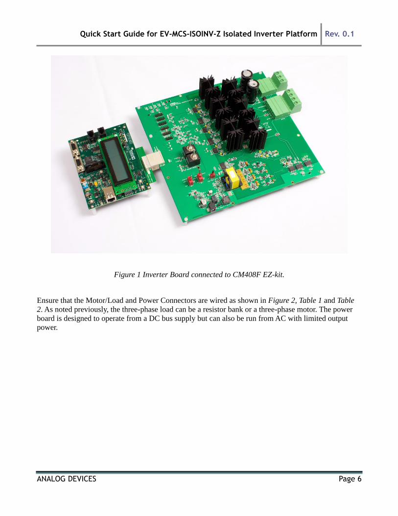
Connect the EZ-kit to the adapter board and the adapter board to the power board as shown in Figure 1.
Quick Start Guide for EV-MCS-ISOINV-Z Isolated Inverter Platform Rev. 0.1
ANALOG DEVICES Page 6
Figure 1 Inverter Board connected to CM408F EZ-kit.
Ensure that the Motor/Load and Power Connectors are wired as shown in Figure 2, Table 1 and Table
2. As noted previously, the three-phase load can be a resistor bank or a three-phase motor. The power
board is designed to operate from a DC bus supply but can also be run from AC with limited output
power.
Quick Start Guide for EV-MCS-ISOINV-Z Isolated Inverter Platform Rev. 0.1
ANALOG DEVICES Page 7
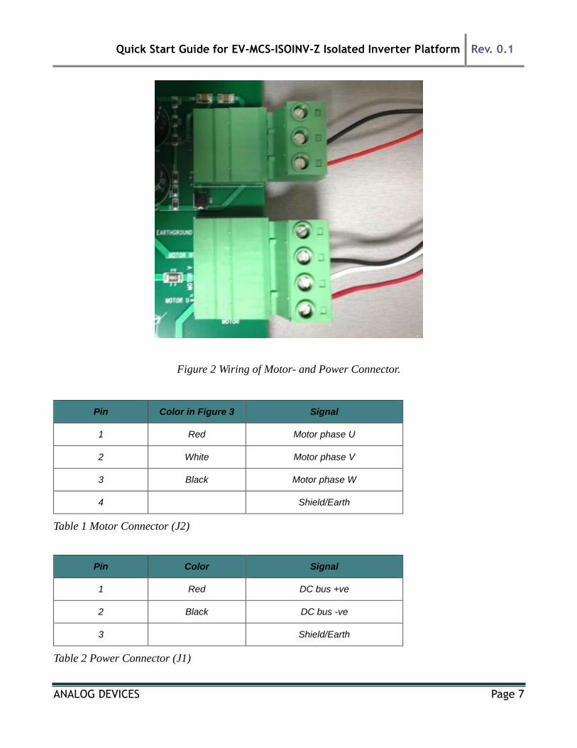
Figure 2 Wiring of Motor- and Power Connector.
Pin Color in Figure 3 Signal
1 Red Motor phase U
2 White Motor phase V
3 Black Motor phase W
4 Shield/Earth
Table 1 Motor Connector (J2)
Pin Color Signal
1 Red DC bus +ve
2 Black DC bus -ve
3 Shield/Earth
Table 2 Power Connector (J1)
Quick Start Guide for EV-MCS-ISOINV-Z Isolated Inverter Platform Rev. 0.1
ANALOG DEVICES Page 8
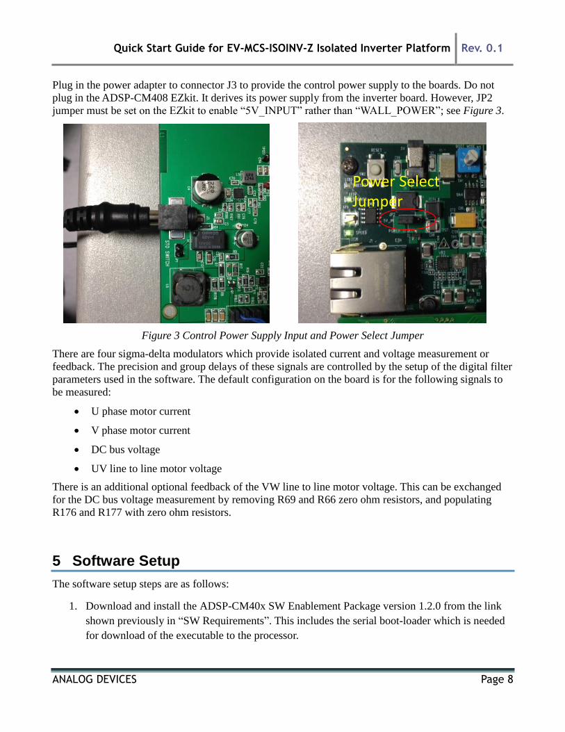
Plug in the power adapter to connector J3 to provide the control power supply to the boards. Do not
plug in the ADSP-CM408 EZkit. It derives its power supply from the inverter board. However, JP2
jumper must be set on the EZkit to enable “5V_INPUT” rather than “WALL_POWER”; see Figure 3.
Figure 3 Control Power Supply Input and Power Select Jumper
There are four sigma-delta modulators which provide isolated current and voltage measurement or
feedback. The precision and group delays of these signals are controlled by the setup of the digital filter
parameters used in the software. The default configuration on the board is for the following signals to
be measured:
U phase motor current
V phase motor current
DC bus voltage
UV line to line motor voltage
There is an additional optional feedback of the VW line to line motor voltage. This can be exchanged
for the DC bus voltage measurement by removing R69 and R66 zero ohm resistors, and populating
R176 and R177 with zero ohm resistors.
5 Software Setup
The software setup steps are as follows:
1. Download and install the ADSP-CM40x SW Enablement Package version 1.2.0 from the link
shown previously in “SW Requirements”. This includes the serial boot-loader which is needed
for download of the executable to the processor.
Power SelectJumper
Quick Start Guide for EV-MCS-ISOINV-Z Isolated Inverter Platform Rev. 0.1
ANALOG DEVICES Page 9
2. Download and install the GUI from the Engineer Zone link provided in “SW Requirements”.
This requires the .NET framework to be on the PC and it will prompt the user to download this
if it is not detected.
3. Download the inverter demo executable program from the Engineer Zone link provided in “SW
Requirements” and program this to the processor board (ADSP-CM408 EZkit).
The first two steps are fairly self-explanatory. The third step – programming of the executable to the
processor – can be carried out in two alternate ways. These are detailed in this section.
5.1 Programming with Serial Downloader
The serial downloader (“wsd.exe”) is provided as part of the ADSP-CM408 SW Enablement Package
and once this has been installed, assuming default installation directory structures, the downloader is
found in C:\Analog Devices\ADSP-CM40x\CM403F_CM408F_EZ-KIT\tool\UARTFlashProgrammer.
This method uses the MC_Demo.hex executable provided at the Engineer Zone link.
Steps:
1. Connect the EZ-kit to the PC using the USB-UART cable: UART (RS-232) connector on the
EZkit, USB on the PC
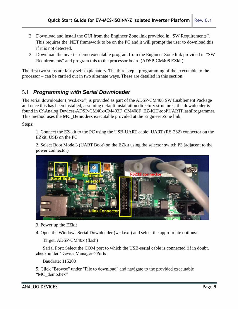
2. Select Boot Mode 3 (UART Boot) on the EZkit using the selector switch P3 (adjacent to the
power connector)
3. Power up the EZkit
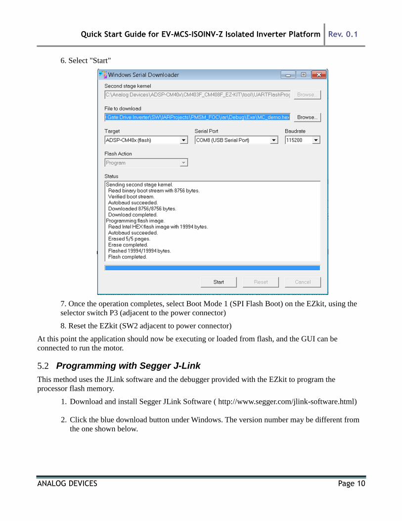
4. Open the Windows Serial Downloader (wsd.exe) and select the appropriate options:
Target: ADSP-CM40x (flash)
Serial Port: Select the COM port to which the USB-serial cable is connected (if in doubt,
check under ‘Device Manager->Ports’
Baudrate: 115200
5. Click "Browse" under "File to download" and navigate to the provided executable
“MC_demo.hex”
RS232 connectorBoot modeselector
Reset Button
J-link Connector
Quick Start Guide for EV-MCS-ISOINV-Z Isolated Inverter Platform Rev. 0.1
ANALOG DEVICES Page 10
6. Select "Start"
7. Once the operation completes, select Boot Mode 1 (SPI Flash Boot) on the EZkit, using the
selector switch P3 (adjacent to the power connector)
8. Reset the EZkit (SW2 adjacent to power connector)
At this point the application should now be executing or loaded from flash, and the GUI can be
connected to run the motor.
5.2 Programming with Segger J-Link
This method uses the JLink software and the debugger provided with the EZkit to program the
processor flash memory.
1. Download and install Segger JLink Software ( http://www.segger.com/jlink-software.html)
2. Click the blue download button under Windows. The version number may be different from
the one shown below.
Quick Start Guide for EV-MCS-ISOINV-Z Isolated Inverter Platform Rev. 0.1
ANALOG DEVICES Page 11
3. Enter your Segger JLink Lite serial number in the next box. This number is printed on the
microcontroller on the debugger board.
4. Click the confirmation box on the next screen, download the software and install (default
location is C:\Program Files(x86)\Segger)
5. Connect the JLink to the PC USB port and the other end to the 20 pin connector on the
CM40x board.
6. The PC will start automatically start installing drivers for your Jlink . Let it complete and
turn on power to the EZkit.
7. Turn on power to the CM408x board.
8. Go to the location where Segger was installed and click on JLink .exe. In this case it is in:
C:\Program Files (x86)\SEGGER\JLink_V490 (The version number and folder name may
be different to the one in this example.)
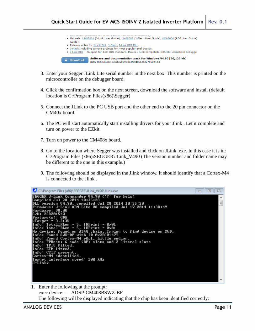
9. The following should be displayed in the Jlink window. It should identify that a Cortex-M4
is connected to the Jlink .
1. Enter the following at the prompt:
exec device = ADSP-CM408BSWZ-BF
The following will be displayed indicating that the chip has been identified correctly:
Quick Start Guide for EV-MCS-ISOINV-Z Isolated Inverter Platform Rev. 0.1
ANALOG DEVICES Page 12
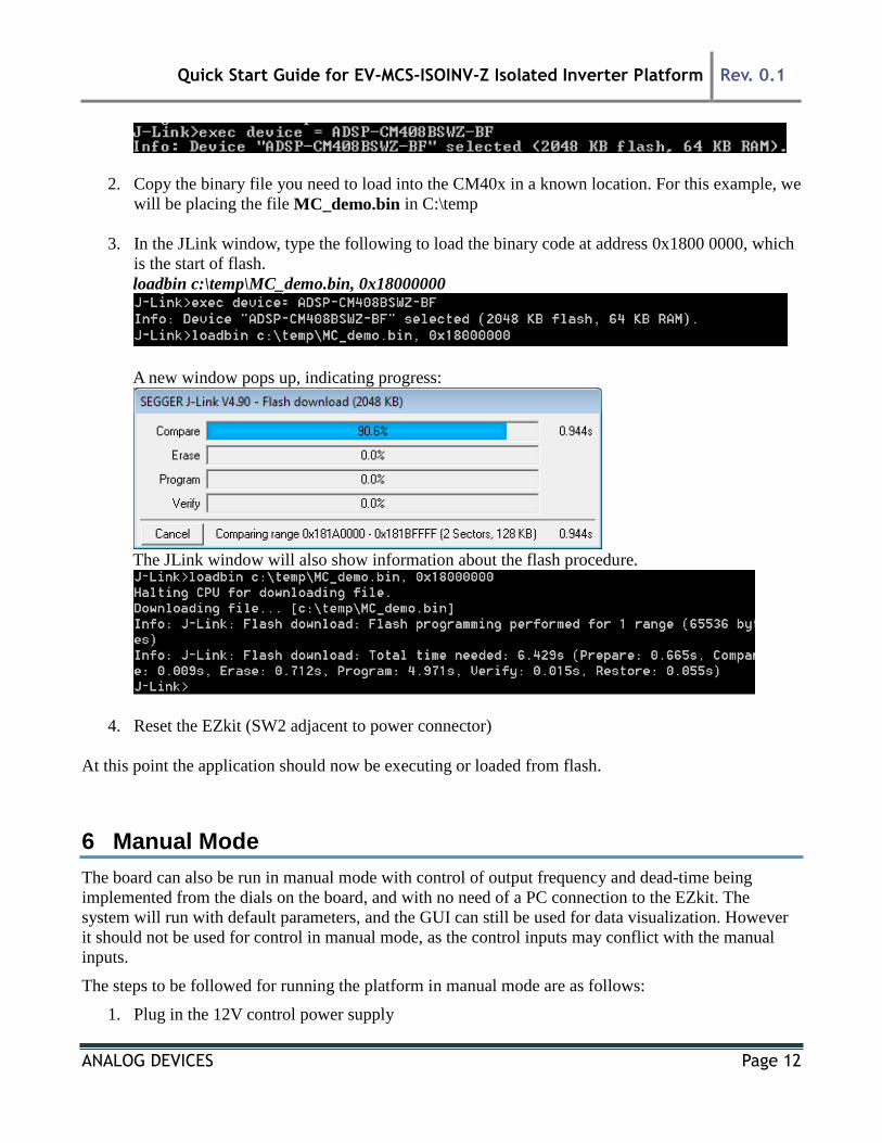
2. Copy the binary file you need to load into the CM40x in a known location. For this example, we
will be placing the file MC_demo.bin in C:\temp
3. In the JLink window, type the following to load the binary code at address 0x1800 0000, which
is the start of flash.
loadbin c:\temp\MC_demo.bin, 0x18000000
A new window pops up, indicating progress:
The JLink window will also show information about the flash procedure.
4. Reset the EZkit (SW2 adjacent to power connector)
At this point the application should now be executing or loaded from flash.
6 Manual Mode
The board can also be run in manual mode with control of output frequency and dead-time being
implemented from the dials on the board, and with no need of a PC connection to the EZkit. The
system will run with default parameters, and the GUI can still be used for data visualization. However
it should not be used for control in manual mode, as the control inputs may conflict with the manual
inputs.
The steps to be followed for running the platform in manual mode are as follows:
1. Plug in the 12V control power supply
Quick Start Guide for EV-MCS-ISOINV-Z Isolated Inverter Platform Rev. 0.1
ANALOG DEVICES Page 13
2. Set the mode selector switch to Manual
3. Set the Start/Stop switch to Stop
4. Reset the EZkit
5. Ensure no fault LEDs are showing
6. Turn on the DC bus power
7. Set the Start/Stop switch to Start
8. Control motor speed/load voltage and frequency with the Frequency dial, and control PWM
dead time with the Dead Time dial
A Safe Torque Off (STO) fault or shutdown can be emulated by shorting the jumper JP1. This will
remove power to the gate drivers, and trigger a PWM fault in the processor. Removing the short and
resetting the fault status by means of the momentary switch SW4 will cause the power board to restore
power to the motor and ramp up the output PWM to its previous operating point (unless the Start/Stop
button has been set to Stop in the meantime).
The LEDs can provide some level of diagnostics as to power supply busses and fault conditions. It
should be noted that if the EZkit is reset, the frequency and dead-time settings revert to their default
start-up values (zero PWM output, and 2s dead-time), i.e. the dials are not absolute position related.
The dead-time range allowed is 500ns to 20s.
7 GUI Mode
Once the installation zip file is extracted, the GUI application is loaded by running the installer executable
“ADIMonitorGUI.exe”. This GUI requires the .NET framework and this will be downloaded if it is not
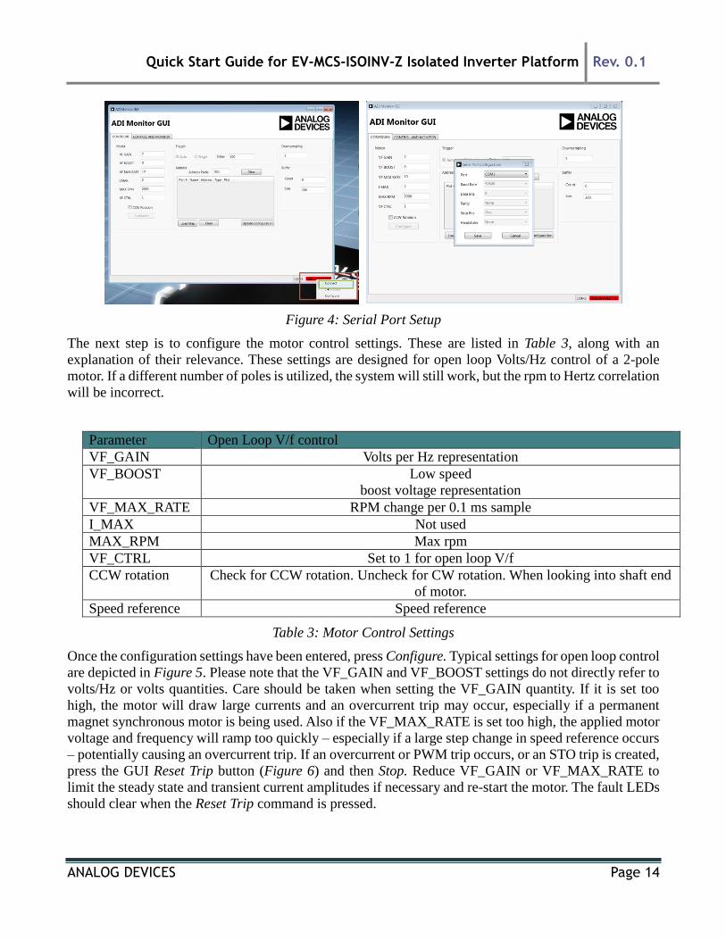
already on the PC. The first step is to set up the serial port (having connected the USB-serial converter
to the EZkit RS232 port). This is accomplished by right-clicking the bottom right-hand corner of the GUI
and selecting Connect. The program should automatically select the correct COM port, but if several
options are available, right-click Configure and select the correct one. Once this is selected press, Save
and then Connect.
Quick Start Guide for EV-MCS-ISOINV-Z Isolated Inverter Platform Rev. 0.1
ANALOG DEVICES Page 14
Figure 4: Serial Port Setup
The next step is to configure the motor control settings. These are listed in Table 3, along with an
explanation of their relevance. These settings are designed for open loop Volts/Hz control of a 2-pole
motor. If a different number of poles is utilized, the system will still work, but the rpm to Hertz correlation
will be incorrect.
Parameter Open Loop V/f control
VF_GAIN Volts per Hz representation
VF_BOOST Low speed
boost voltage representation
VF_MAX_RATE RPM change per 0.1 ms sample
I_MAX Not used
MAX_RPM Max rpm
VF_CTRL Set to 1 for open loop V/f
CCW rotation Check for CCW rotation. Uncheck for CW rotation. When looking into shaft end
of motor.
Speed reference Speed reference
Table 3: Motor Control Settings
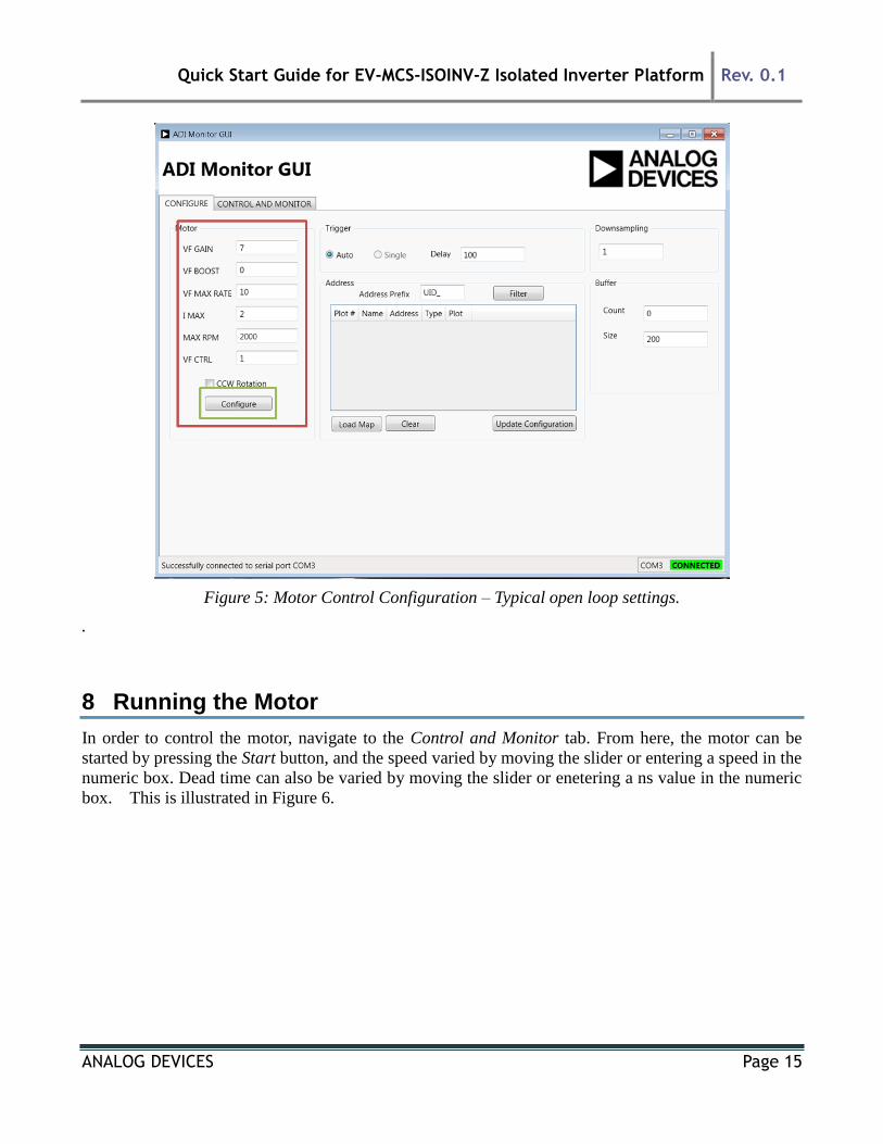
Once the configuration settings have been entered, press Configure. Typical settings for open loop control
are depicted in Figure 5. Please note that the VF_GAIN and VF_BOOST settings do not directly refer to
volts/Hz or volts quantities. Care should be taken when setting the VF_GAIN quantity. If it is set too
high, the motor will draw large currents and an overcurrent trip may occur, especially if a permanent
magnet synchronous motor is being used. Also if the VF_MAX_RATE is set too high, the applied motor
voltage and frequency will ramp too quickly – especially if a large step change in speed reference occurs
– potentially causing an overcurrent trip. If an overcurrent or PWM trip occurs, or an STO trip is created,
press the GUI Reset Trip button (Figure 6) and then Stop. Reduce VF_GAIN or VF_MAX_RATE to
limit the steady state and transient current amplitudes if necessary and re-start the motor. The fault LEDs
should clear when the Reset Trip command is pressed.
Quick Start Guide for EV-MCS-ISOINV-Z Isolated Inverter Platform Rev. 0.1
ANALOG DEVICES Page 15
Figure 5: Motor Control Configuration – Typical open loop settings.
.
8 Running the Motor
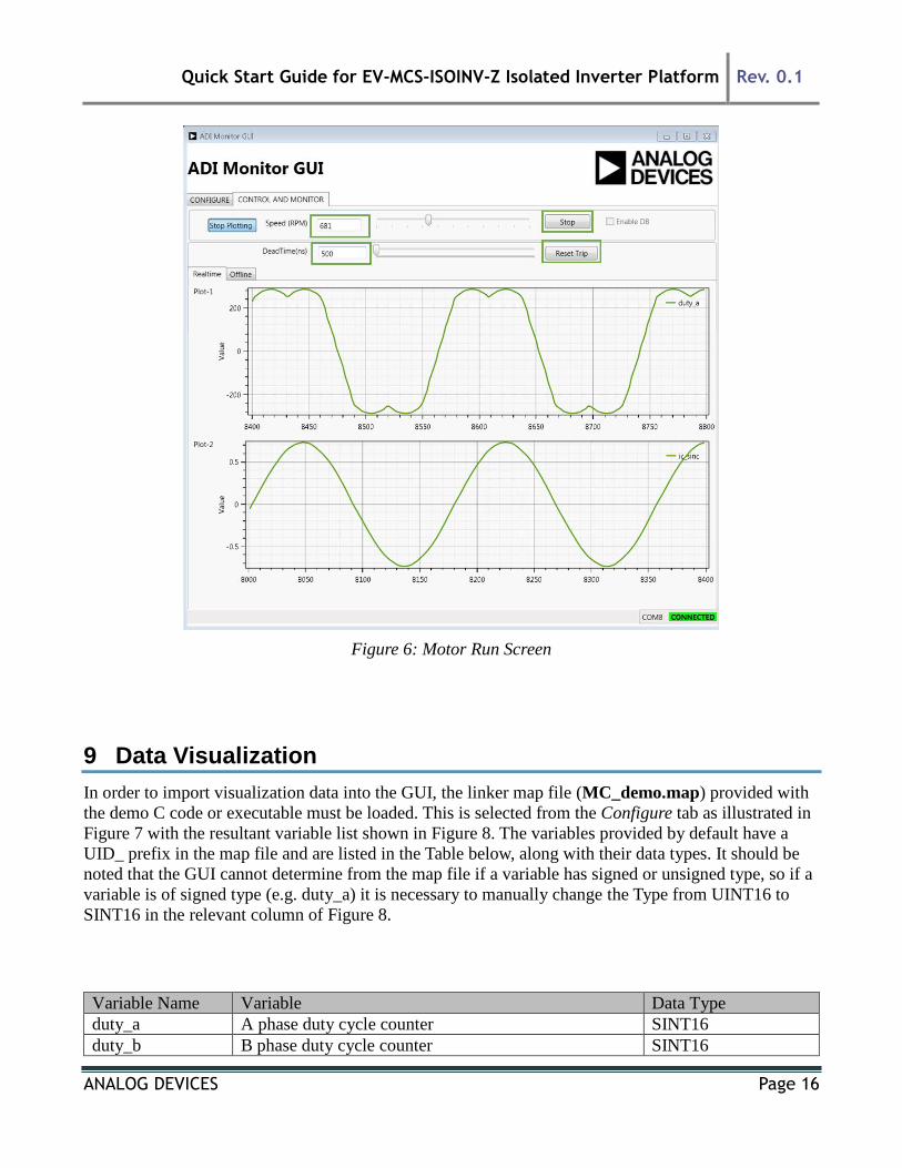
In order to control the motor, navigate to the Control and Monitor tab. From here, the motor can be
started by pressing the Start button, and the speed varied by moving the slider or entering a speed in the
numeric box. Dead time can also be varied by moving the slider or enetering a ns value in the numeric
box. This is illustrated in Figure 6.
Quick Start Guide for EV-MCS-ISOINV-Z Isolated Inverter Platform Rev. 0.1
ANALOG DEVICES Page 16
Figure 6: Motor Run Screen
9 Data Visualization
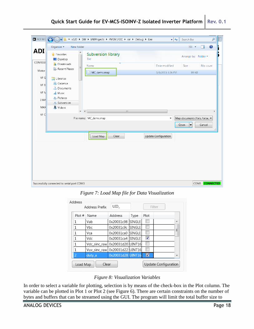
In order to import visualization data into the GUI, the linker map file (MC_demo.map) provided with
the demo C code or executable must be loaded. This is selected from the Configure tab as illustrated in
Figure 7 with the resultant variable list shown in Figure 8. The variables provided by default have a
UID_ prefix in the map file and are listed in the Table below, along with their data types. It should be
noted that the GUI cannot determine from the map file if a variable has signed or unsigned type, so if a
variable is of signed type (e.g. duty_a) it is necessary to manually change the Type from UINT16 to
SINT16 in the relevant column of Figure 8.
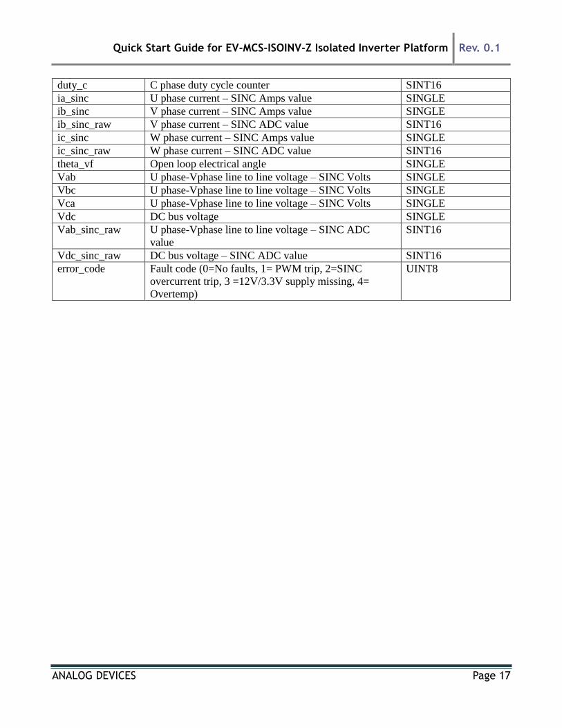
Variable Name Variable Data Type
duty_a A phase duty cycle counter SINT16
duty_b B phase duty cycle counter SINT16
Quick Start Guide for EV-MCS-ISOINV-Z Isolated Inverter Platform Rev. 0.1
ANALOG DEVICES Page 17
duty_c C phase duty cycle counter SINT16
ia_sinc U phase current – SINC Amps value SINGLE
ib_sinc V phase current – SINC Amps value SINGLE
ib_sinc_raw V phase current – SINC ADC value SINT16
ic_sinc W phase current – SINC Amps value SINGLE
ic_sinc_raw W phase current – SINC ADC value SINT16
theta_vf Open loop electrical angle SINGLE
Vab U phase-Vphase line to line voltage – SINC Volts SINGLE
Vbc U phase-Vphase line to line voltage – SINC Volts SINGLE
Vca U phase-Vphase line to line voltage – SINC Volts SINGLE
Vdc DC bus voltage SINGLE
Vab_sinc_raw U phase-Vphase line to line voltage – SINC ADC
value
SINT16
Vdc_sinc_raw DC bus voltage – SINC ADC value SINT16
error_code Fault code (0=No faults, 1= PWM trip, 2=SINC
overcurrent trip, 3 =12V/3.3V supply missing, 4=
Overtemp)
UINT8
Quick Start Guide for EV-MCS-ISOINV-Z Isolated Inverter Platform Rev. 0.1
ANALOG DEVICES Page 18
Figure 7: Load Map file for Data Visualization
Figure 8: Visualization Variables
In order to select a variable for plotting, selection is by means of the check-box in the Plot column. The
variable can be plotted in Plot 1 or Plot 2 (see Figure 6). There are certain constraints on the number of
bytes and buffers that can be streamed using the GUI. The program will limit the total buffer size to
Quick Start Guide for EV-MCS-ISOINV-Z Isolated Inverter Platform Rev. 0.1
ANALOG DEVICES Page 19
1.7k bytes. The number of variables plotted can be increased by reducing the buffer size, which is
maximum 200, although a total maximum selected variable size of 8 bytes is allowed (e.g. 2xSINGLE
or 4xINT16, or 1xSINGLE+2xINT16 etc).
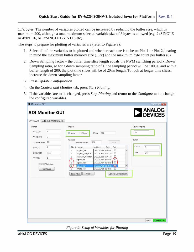
The steps to prepare for plotting of variables are (refer to Figure 9):
1. Select all of the variables to be plotted and whether each one is to be on Plot 1 or Plot 2, bearing
in mind the maximum buffer memory size (1.7k) and the maximum byte count per buffer (8).
2. Down Sampling factor – the buffer time slice length equals the PWM switching period x Down
Sampling ratio, so for a down sampling ratio of 1, the sampling period will be 100s, and with a
buffer length of 200, the plot time slices will be of 20ms length. To look at longer time slices,
increase the down sampling factor.
3. Press Update Configuration
4. On the Control and Monitor tab, press Start Plotting.
5. If the variables are to be changed, press Stop Plotting and return to the Configure tab to change
the configured variables.
Figure 9: Setup of Variables for Plotting
Quick Start Guide for EV-MCS-ISOINV-Z Isolated Inverter Platform Rev. 0.1
ANALOG DEVICES Page 20
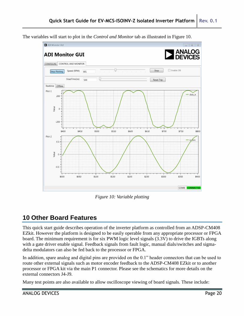
The variables will start to plot in the Control and Monitor tab as illustrated in Figure 10.
Figure 10: Variable plotting
10 Other Board Features
This quick start guide describes operation of the inverter platform as controlled from an ADSP-CM408
EZkit. However the platform is designed to be easily operable from any appropriate processor or FPGA
board. The minimum requirement is for six PWM logic level signals (3.3V) to drive the IGBTs along
with a gate driver enable signal. Feedback signals from fault logic, manual dials/switches and sigma-
delta modulators can also be fed back to the processor or FPGA.
In addition, spare analog and digital pins are provided on the 0.1” header connectors that can be used to
route other external signals such as motor encoder feedback to the ADSP-CM408 EZkit or to another
processor or FPGA kit via the main P1 connector. Please see the schematics for more details on the
external connectors J4-J9.
Many test points are also available to allow oscilloscope viewing of board signals. These include:

Quick Start Guide for EV-MCS-ISOINV-Z Isolated Inverter Platform Rev. 0.1
ANALOG DEVICES Page 21
Controller-side and isolated power supply voltages
All gate drive signals, both logic-level and isolated
All sigma-delta modulator clock and data signals
Analog filtered outputs of the sigma-delta bit streams that provide an analog representation of U
and V phase currents and the U-V motor line to line voltage
Fault signals, enable signals and manual dial outputs
As mentioned previously, a digital PFC controller evaluation board can be connected to the input to
enable operation from ac mains up to 300-600W. An I2C isolator and connector is available to connect
this board to the I2C connector on one of the PFC evaluation boards, so that the PFC evaluation board
can be controlled from the control processor or FPGA.
11 Support
For support issues on setup and operation of the EV-MCS-ISOINV-Z platform, please visit the
Engineer Zone support site at https://ez.analog.com/community/motor-control-hardware-platforms2 .
For other support issues:
- Visit the Technical Support web site at http://www.analog.com/support
- For processor and processor tools specific questions, visit https://ez.analog.com/community/dsp
or email [email protected]
- E-mail processor questions to [email protected] [email protected]
(China and Taiwan only)
- Phone questions to 1-800-ANALOGD
- Contact your Analog Devices, Inc. local sales office or authorized distributor
- Send questions by mail to: Analog Devices, Inc. 3 Technology Way P.O. Box 9106 Norwood,
MA 02062-9106 USA