Embed Size (px)
Citation preview

HUAWEI TECHNOLOGIES CO., LTD
Quick Start GuideS2700&S3700&S5700&S6700 Series Switches
Issue: 17(2014-11-20)Part Number: 31504991

Packing List
Safety Guidelines
Site Environment
1
Chassis (with the product model on the nameplate)Power cable (Power cables are delivered with the
switch if the switch is equipped with built-in power
supply or pluggable power modules, and are delivered
with power modules in other cases.)
Installation accessory package:- Open Source Software Notice
- Console cable
-
- Floating nuts
- Rubber pads
- Chassis ground cable
- Warranty Card
- Mounting brackets
- Screws
- Dust plugs
The numbers and types of items in the installation accessory package differ for different product models.
Some switches have dust plugs delivered with them. Keep the dust plugs properly and use them to protect idle optical ports.
NOTE
To ensure personal and equipment safety, observe all the safety precautions on the equipment and in
this document. and items do not cover all the safety precautions and are only
supplementary to the safety precautions.
Follow all the safety precautions and instructions provided by Huawei. The safety precautions outlined
in this document are only requirements of Huawei and do not include general safety requirements.
Huawei is not liable for any consequence that results from violation of regulations pertaining to safe
operations or safety codes pertaining to design, production, and equipment use.
WARNING CAUTION
Take ESD protection measures during equipment installation and maintenance. For example, wear ESD gloves or an ESD
wrist strap.
During equipment transport and installation, prevent the equipment from colliding with objects like doors, walls, or shelves.
Do not touch unpainted metal surfaces of equipment components with wet or contaminated gloves.
Do not place other objects on the chassis.
WARNING
CAUTION
This is a class A product. In a domestic environment this product may cause radio interference in which case the user may be required to take adequate measures.
The installation, cable connection, and login methods for S series switches are similar. This document uses
S5700-24TP-SI-AC as an example. For more information, see the .
Figures in the document are for reference only and may be different from actual devices.
NOTE
Do not place this product in an environment with flammable or explosive gases, or smoke.
The installation site must be free from leaking or dripping water, heavy dew, and humidity. If the relative
humidity is high, use dehumidifiers or air conditioners with dehumidification features.
The installation site must be well ventilated. Ensure that air vents on the equipment are not blocked.
Do not install the equipment in a dusty environment.
Leave at least 50 mm clearance at the rear and both sides of the chassis for heat dissipation.50mm
Hardware Installation and Maintenance Guide
Quick Start Guide
Installing the Chassis
2
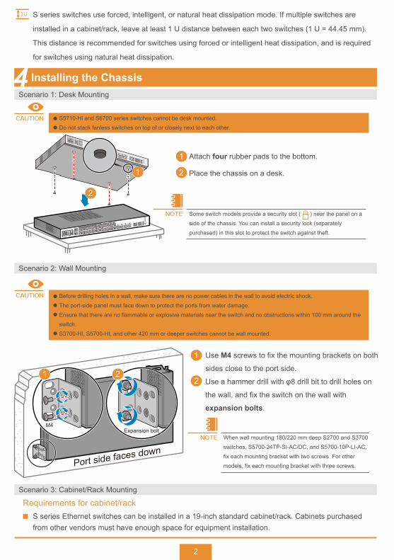
S series switches use forced, intelligent, or natural heat dissipation mode. If multiple switches are
installed in a cabinet/rack, leave at least 1 U distance between each two switches (1 U = 44.45 mm).
This distance is recommended for switches using forced or intelligent heat dissipation, and is required
for switches using natural heat dissipation.
Scenario 1: Desk Mounting
Scenario 2: Wall Mounting
Scenario 3: Cabinet/Rack Mounting
S5710-HI and S6700 series switches cannot be desk mounted.
Do not stack fanless switches on top of or closely next to each other.
1
2
Attach four rubber pads to the bottom.
Place the chassis on a desk.
Some switch models provide a security slot ( ) near the panel on a
side of the chassis. You can install a security lock (separately
purchased) in this slot to protect the switch against theft.
1
2
S series Ethernet switches can be installed in a 19-inch standard cabinet/rack. Cabinets purchased from other vendors must have enough space for equipment installation.
Requirements for cabinet/rack
Before drilling holes in a wall, make sure there are no power cables in the wall to avoid electric shock.
The port-side panel must face down to protect the ports from water damage.
Ensure that there are no flammable or explosive materials near the switch and no obstructions within 100 mm around the
switch.
S3700-HI, S5700-HI, and other 420 mm or deeper switches cannot be wall mounted.
M4Expansion bolt
1 2
Port side faces downWhen wall mounting 180/220 mm deep S2700 and S3700
switches, S5700-24TP-SI-AC/DC, and S5700-10P-LI-AC,
fix each mounting bracket with two screws. For other
models, fix each mounting bracket with three screws.
Use M4 screws to fix the mounting brackets on both
sides close to the port side.
Use a hammer drill with φ8 drill bit to drill holes on
the wall, and fix the switch on the wall with
expansion bolts.
1
2
CAUTION
CAUTION
NOTE
NOTE
1U
3
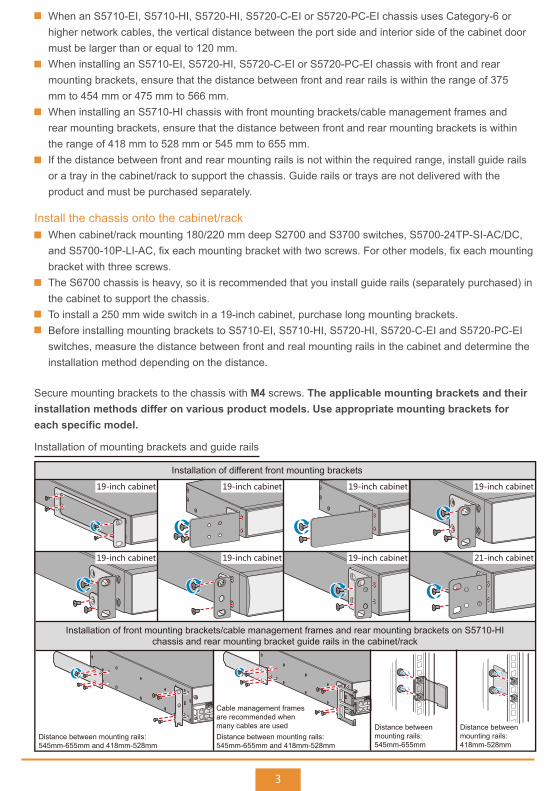
When cabinet/rack mounting 180/220 mm deep S2700 and S3700 switches, S5700-24TP-SI-AC/DC, and S5700-10P-LI-AC, fix each mounting bracket with two screws. For other models, fix each mounting bracket with three screws.The S6700 chassis is heavy, so it is recommended that you install guide rails (separately purchased) in the cabinet to support the chassis.To install a 250 mm wide switch in a 19-inch cabinet, purchase long mounting brackets.Before installing mounting brackets to S5710-EI, S5710-HI, S5720-HI, S5720-C-EI and S5720-PC-EI switches, measure the distance between front and real mounting rails in the cabinet and determine the installation method depending on the distance.
Install the chassis onto the cabinet/rack
Secure mounting brackets to the chassis with M4 screws. The applicable mounting brackets and their installation methods differ on various product models. Use appropriate mounting brackets for each specific model.
Installation of different front mounting brackets
19-inch cabinet 19-inch cabinet 19-inch cabinet 19-inch cabinet
19-inch cabinet 19-inch cabinet 19-inch cabinet 21-inch cabinet
Installation of front mounting brackets/cable management frames and rear mounting brackets on S5710-HIchassis and rear mounting bracket guide rails in the cabinet/rack
Cable management framesare recommended whenmany cables are used
Distance between mounting rails:545mm-655mm and 418mm-528mm
Distance between mounting rails:545mm-655mm and 418mm-528mm
Distance betweenmounting rails:545mm-655mm
Distance betweenmounting rails:418mm-528mm
When an S5710-EI, S5710-HI, S5720-HI, S5720-C-EI or S5720-PC-EI chassis uses Category-6 or higher network cables, the vertical distance between the port side and interior side of the cabinet door must be larger than or equal to 120 mm.When installing an S5710-EI, S5720-HI, S5720-C-EI or S5720-PC-EI chassis with front and rear mounting brackets, ensure that the distance between front and rear rails is within the range of 375 mm to 454 mm or 475 mm to 566 mm.When installing an S5710-HI chassis with front mounting brackets/cable management frames and rear mounting brackets, ensure that the distance between front and rear mounting brackets is within the range of 418 mm to 528 mm or 545 mm to 655 mm.If the distance between front and rear mounting rails is not within the required range, install guide rails or a tray in the cabinet/rack to support the chassis. Guide rails or trays are not delivered with the product and must be purchased separately.
Installation of mounting brackets and guide rails
4
When installing an S5710-EI, S5710-HI, S5720-HI, S5720-C-EI and S5720-PC-EI align both rear mounting brackets with the
guide rails, and then slowly slide the rear mounting brackets along the guide rails.
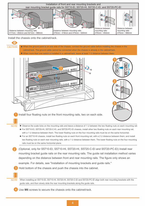
Hold bottom of the chassis and push the chassis into the cabinet.3
Use M6 screws to secure the chassis onto the cabinet/rack.4
NOTE
Distance between mounting rails:417mm~454mm and 521mm~566mm
Distance between mounting rails:375mm~416mm and 475mm~520mm
Distance betweenmounting rails:375mm~454mm
Distance betweenmounting rails:475mm~566mm
Installation of front and rear mounting brackets andrear mounting bracket guide rails for S5710-EI, S5720-HI, S5720-C-EI, and S5720-PC-EI
When the ground point is on one side of the chassis, connect the ground cable before installing the chassis in the
cabinet/rack. The ground cable cannot be connected when the chassis is already in the cabinet/rack.
When more than one switch is installed in a cabinet/rack, leave at least 1 U distance between them.
CAUTION
Install the chassis onto the cabinet/rack.
≥1U
1U
1
3
4
5
Observe the scale ticks on the mounting rails and leave a distance of 1 U between the two floating nuts on each mounting rail.
For S5710-EI, S5720-HI, S5720-C-EI, and S5720-PC-EI chassis, install other two floating nuts on each rear mounting rail,
with a 1 U distance between them. The lower floating nuts on the four mounting rails must be on the same horizontal.
For an S5710-HI chassis, install two floating nuts on each front mounting rail, with a 2 U distance between them, and install
two floating nuts on each rear mounting rails, with a 1 U distance between them. The lower floating nuts on the four mounting
rails must be on the same horizontal plane.
Install four floating nuts on the front mounting rails, two on each side.
(Optional, only for S5710-EI, S5710-HI, S5720-HI, S5720-C-EI and S5720-PC-EI) Install rear mounting bracket guide rails on the rear mounting rails. The guide rail installation method varies depending on the distance between front and rear mounting rails. The figure only shows an
example. For details, see "Installation of mounting brackets and guide rails."
1
2
NOTE
2
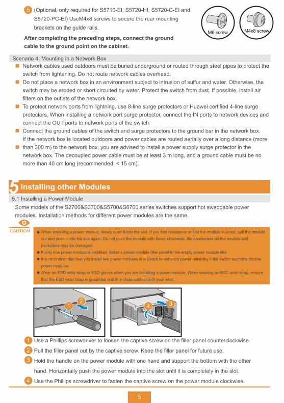
(Optional, only required for S5710-EI, S5720-HI, S5720-C-EI and S5720-PC-EI) UseM4x8 screws to secure the rear mounting brackets on the guide rails.
5
After completing the preceding steps, connect the ground cable to the ground point on the cabinet.
M6 screw M4x8 screw
5
Scenario 4: Mounting in a Network BoxNetwork cables used outdoors must be buried underground or routed through steel pipes to protect the switch from lightening. Do not route network cables overhead.Do not place a network box in an environment subject to intrusion of sulfur and water. Otherwise, the switch may be eroded or short circuited by water. Protect the switch from dust. If possible, install air filters on the outlets of the network box.To protect network ports from lightning, use 8-line surge protectors or Huawei certified 4-line surge protectors. When installing a network port surge protector, connect the IN ports to network devices and connect the OUT ports to network ports of the switch.Connect the ground cables of the switch and surge protectors to the ground bar in the network box.If the network box is located outdoors and power cables are routed aerially over a long distance (more than 300 m) to the network box, you are advised to install a power supply surge protector in the network box. The decoupled power cable must be at least 3 m long, and a ground cable must be no more than 40 cm long (recommended: < 15 cm).
Some models of the S2700&S3700&S5700&S6700 series switches support hot swappable power modules. Installation methods for different power modules are the same.
Installing other Modules5.1 Installing a Power Module
When installing a power module, slowly push it into the slot. If you feel resistance or find the module inclined, pull the module
out and push it into the slot again. Do not push the module with force; otherwise, the connectors on the module and
backplane may be damaged.
If only one power module is installed, install a power module filler panel in the empty power module slot.
It is recommended that you install two power modules in a switch to enhance power reliability if the switch supports double
power modules.
Wear an ESD wrist strap or ESD gloves when you are installing a power module. When wearing an ESD wrist strap, ensure
that the ESD wrist strap is grounded and in a close contact with your wrist.
CAUTION
Use a Phillips screwdriver to loosen the captive screw on the filler panel counterclockwise.
Pull the filler panel out by the captive screw. Keep the filler panel for future use.
Hold the handle on the power module with one hand and support the bottom with the other
hand. Horizontally push the power module into the slot until it is completely in the slot.
Use the Phillips screwdriver to fasten the captive screw on the power module clockwise.
12
4
3
12
4 3
6
Connecting Cables
Laser beams will cause eye damage. Do not look into bores of optical modules or optical fibers without eye protection.
Do not install power cables while the power is on.
Do not turn on the power until you have finished installing the chassis and connecting cables.
WARNING
The PGND cable on the chassis must be grounded. The ground point on a network box, cabinet, or rack must be reliably
grounded. If the ground point is covered by anti-rust coating, scrape off the paint around the ground point to ensure reliable
grounding.
Power cables must be more than 10 cm away from signal cables.
The bend radius of optical fibers must be larger than 40 mm.
CAUTION
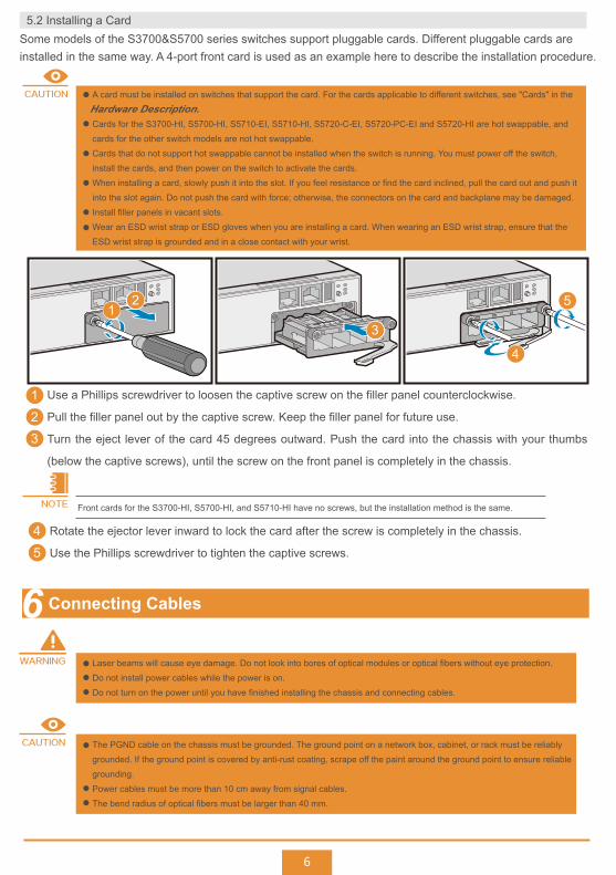
A card must be installed on switches that support the card. For the cards applicable to different switches, see "Cards" in the
Cards for the S3700-HI, S5700-HI, S5710-EI, S5710-HI, S5720-C-EI, S5720-PC-EI and S5720-HI are hot swappable, and
cards for the other switch models are not hot swappable.
Cards that do not support hot swappable cannot be installed when the switch is running. You must power off the switch,
install the cards, and then power on the switch to activate the cards.
When installing a card, slowly push it into the slot. If you feel resistance or find the card inclined, pull the card out and push it
into the slot again. Do not push the card with force; otherwise, the connectors on the card and backplane may be damaged.
Install filler panels in vacant slots.
Wear an ESD wrist strap or ESD gloves when you are installing a card. When wearing an ESD wrist strap, ensure that the
ESD wrist strap is grounded and in a close contact with your wrist.
CAUTION
Hardware Description.
Use a Phillips screwdriver to loosen the captive screw on the filler panel counterclockwise.
Pull the filler panel out by the captive screw. Keep the filler panel for future use.
Turn the eject lever of the card 45 degrees outward. Push the card into the chassis with your thumbs
(below the captive screws), until the screw on the front panel is completely in the chassis.
123
12
3
4
5
Rotate the ejector lever inward to lock the card after the screw is completely in the chassis.
Use the Phillips screwdriver to tighten the captive screws.
45
Front cards for the S3700-HI, S5700-HI, and S5710-HI have no screws, but the installation method is the same.NOTE
Some models of the S3700&S5700 series switches support pluggable cards. Different pluggable cards are installed in the same way. A 4-port front card is used as an example here to describe the installation procedure.
5.2 Installing a Card
7
Logging In to the Switch for the First Time
2
CONSOLE ETH USB
PWR
RPS
SYS
SPEED
PWR
-12V;5A
ON
OFF
-100-240V;50/60 Hz 1.5A
+
-
Quidway S5700 Series
1 2 3 44 5 6
7
Managementnetwork
No. No.
1
2
3
4
5
6
7
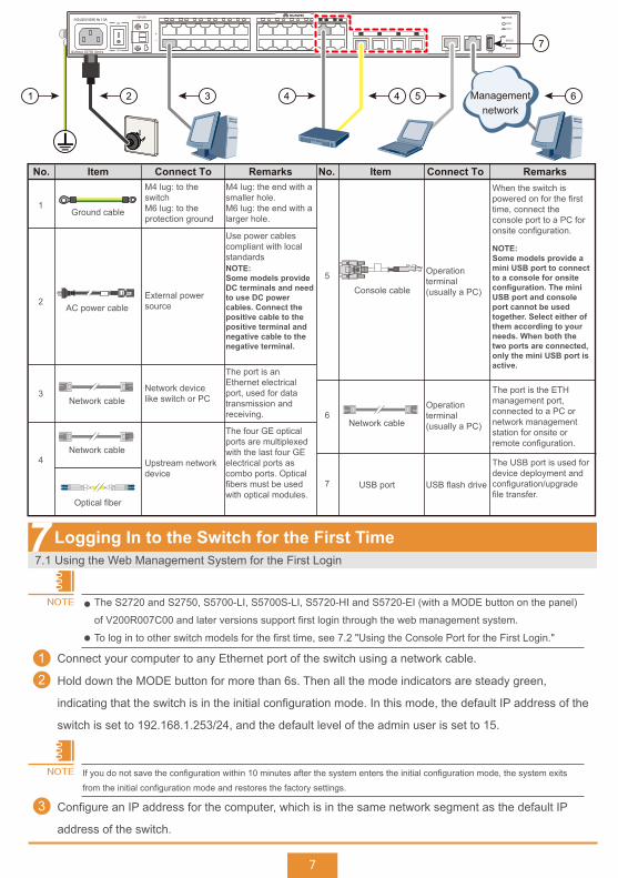
Item ItemConnect To Connect ToRemarks RemarksM4 lug: to the switchM6 lug: to the protection ground
External power source
Upstream network device
USB flash driveUSB port
Network device like switch or PC
Operation terminal (usually a PC)
Operation terminal (usually a PC)
The port is an Ethernet electrical port, used for data transmission and receiving.
M4 lug: the end with a smaller hole.M6 lug: the end with a larger hole.
Use power cables compliant with local standards
When the switch is powered on for the first time, connect the console port to a PC for onsite configuration.
NOTE:Some models provide a mini USB port to connect to a console for onsite configuration. The mini USB port and console port cannot be used together. Select either of them according to your needs. When both the two ports are connected, only the mini USB port is active.
The four GE optical ports are multiplexed with the last four GE electrical ports as combo ports. Optical fibers must be used with optical modules.
The port is the ETH management port, connected to a PC or network management station for onsite or remote configuration.
The USB port is used for device deployment and configuration/upgrade file transfer.
Ground cable
AC power cable
Network cable
Network cable
Network cable
Optical fiber
Console cable
NOTE:Some models provide DC terminals and need to use DC power cables. Connect the positive cable to the positive terminal and negative cable to the negative terminal.
The S2720 and S2750, S5700-LI, S5700S-LI, S5720-HI and S5720-EI (with a MODE button on the panel)
of V200R007C00 and later versions support first login through the web management system.
To log in to other switch models for the first time, see 7.2 "Using the Console Port for the First Login."
NOTE
Connect your computer to any Ethernet port of the switch using a network cable.1
Hold down the MODE button for more than 6s. Then all the mode indicators are steady green,
indicating that the switch is in the initial configuration mode. In this mode, the default IP address of the
switch is set to 192.168.1.253/24, and the default level of the admin user is set to 15.
3 Configure an IP address for the computer, which is in the same network segment as the default IP
address of the switch.
If you do not save the configuration within 10 minutes after the system enters the initial configuration mode, the system exits
from the initial configuration mode and restores the factory settings.
NOTE
7.1 Using the Web Management System for the First Login

8
Use Microsoft Internet Explorer 8.0, Mozilla Firefox
12.0, Google Chrome 23.0, or later versions of
these browsers. Earlier versions of browsers may
cause abnormal display on the web pages.
NOTE
The method to change the IP address on your PC depends on the architecture and operating system of your PC. Search for "IP
addressing" in the user manual or online help of your PC to find operation instructions.
NOTE
Start the web browser on the computer, enter https://192.168.1.253 in the address box, and press
Enter to display the initial login page. Enter the default user name admin and default password
[email protected] and select the language on the login page. Then click GO to display the
web-based configuration page.
4
Configure the switch. The web-based configuration page provides basic and optional configuration
items. The basic configuration enables you to log in to the switch using the web management system,
and the optional configuration enables you to log in to the switch using Telnet or STelnet. Only
parameters for the basic configuration are described below. For details about the optional
configuration and more information about the product, see the of the product.
5
Configuration Item
Management IP Address
Description
Mandatory. Enter the management IP address of the switch, in dotted decimal notation.
Mask Mandatory. Select a subnet mask from the drop-down list box.
Old Password
Confirm Password
Mandatory. Enter the old password for the default web user.
Mandatory. Enter the new password again.
WEB User Level Optional. Select a user level from the drop-down list box. The user of level 3 or higher has management rights.
WEB User Password Mandatory. Enter a new password for the default web user.To ensure password strength, the password must contain at least two types of the following: lowercase letters, uppercase letters, digits, and special characters (such as ! $ # %), and cannot contain any space or single quotation mark.
Configuration Guide
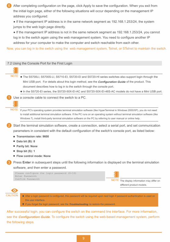
Press Enter in subsequent steps until the following information is displayed on the terminal simulation software, and then enter a password.
3
The display information may differ on
different product models.
NOTE
Please configure the login password (6-16)Enter Password: Confirm Password:
After a login password is configured, this password will be required upon next login if password authentication is used on
this user interface.
If you forget the login password, see the to restore the password.
CAUTION
Troubleshooting
After successful login, you can configure the switch on the command line interface. For more information, see the . To configure the switch using the web-based management system, perform the following steps.
9
Use a console cable to connect the switch to a PC.
Start the terminal simulation software, create a connection, select a serial port, and set communication parameters in consistent with the default configuration of the switch's console port, as listed below:
1
After completing configuration on the page, click Apply to save the configuration. When you exit from the initial login page, either of the following situations will occur depending on the management IP address you configured:● If the management IP address is in the same network segment as 192.168.1.253/24, the system jumps to the web login page directly.● If the management IP address is not in the same network segment as 192.168.1.253/24, you cannot log in to the switch again using the web management system. You need to configure another IP address for your computer to make the computer and switch reachable from each other.
6
2
If your PC's operating system provides terminal simulation software (like HyperTerminal in Windows 2000/XP), you do not need
to install additional terminal simulation software. If the PC runs on an operating system without terminal simulation software (like
Windows 7), install third-party terminal simulation software on the PC by referring to user manual or online help.
NOTE
Transmission rate: 9600Data bit (B): 8Parity bit: NoneStop bit (S): 1Flow control mode: None
Now, you can log in to the switch using the web management system, Telnet, or STelnet to maintain the switch.
7.2 Using the Console Port for the First Login
NOTE The S5700LI, S5700S-LI, S5710-EI, S5720-EI and S5720-HI series switches also support login through the
Mini USB port. For details about this login method, see the of the product. This
document describes how to log in to the switch through the console port.
In the S5720-EI series, the S5720-50X-EI-AC and S5720-50X-EI-46S-AC models do not have a Mini USB port.
Configuration Guide
Configuration Guide
10
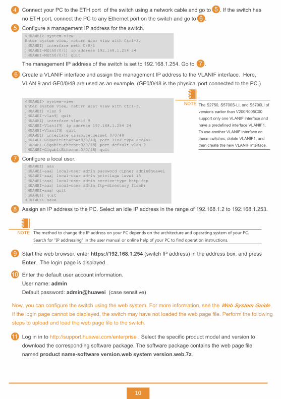
Now, you can configure the switch using the web system. For more information, see the .If the login page cannot be displayed, the switch may have not loaded the web page file. Perform the following steps to upload and load the web page file to the switch.
Connect your PC to the ETH port of the switch using a network cable and go to . If the switch has no ETH port, connect the PC to any Ethernet port on the switch and go to .
The management IP address of the switch is set to 192.168.1.254. Go to .
Configure a management IP address for the switch.
4
5
Create a VLANIF interface and assign the management IP address to the VLANIF interface. Here, VLAN 9 and GE0/0/48 are used as an example. (GE0/0/48 is the physical port connected to the PC.)
6
56
7
<HUAWEI> system-viewEnter system view, return user view with Ctrl+Z.[HUAWEI] interface meth 0/0/1[HUAWEI-MEth0/0/1] ip address 192.168.1.254 24[HUAWEI-MEth0/0/1] quit
The S2750, S5700S-LI, and S5700LI of
versions earlier than V200R005C00
support only one VLANIF interface and
have a predefined interface VLANIF1.
To use another VLANIF interface on
these switches, delete VLANIF1, and
then create the new VLANIF interface.
NOTE<HUAWEI> system-viewEnter system view, return user view with Ctrl+Z.[HUAWEI] vlan 9[HUAWEI-vlan9] quit[HUAWEI] interface vlanif 9[HUAWEI-Vlanif9] ip address 192.168.1.254 24[HUAWEI-Vlanif9] quit[HUAWEI] interface gigabitethernet 0/0/48[HUAWEI-GigabitEthernet0/0/48] port link-type access[HUAWEI-GigabitEthernet0/0/48] port default vlan 9[HUAWEI-GigabitEthernet0/0/48] quit
Start the web browser, enter https://192.168.1.254 (switch IP address) in the address box, and press Enter. The login page is displayed.
9
Enter the default user account information.User name: adminDefault password: admin@huawei (case sensitive)
10
Assign an IP address to the PC. Select an idle IP address in the range of 192.168.1.2 to 192.168.1.253.8
The method to change the IP address on your PC depends on the architecture and operating system of your PC.
Search for "IP addressing" in the user manual or online help of your PC to find operation instructions.
NOTE
Configure a local user.7[HUAWEI] aaa[HUAWEI-aaa] local-user admin password cipher admin@huawei[HUAWEI-aaa] local-user admin privilege level 15[HUAWEI-aaa] local-user admin service-type http ftp[HUAWEI-aaa] local-user admin ftp-directory flash:[HUAWEI-aaa] quit[HUAWEI] quit<HUAWEI> save
Log in in to http://support.huawei.com/enterprise . Select the specific product model and version to download the corresponding software package. The software package contains the web page file named product name-software version.web system version.web.7z.
11
Web System Guide

Obtaining Product Documentation and Technical Support
Trademarks and Permissions
11
Enterprise network technical bulletin:http://support.huawei.com/ecommunity
You can obtain the latest product documentation at http://support.huawei.com/enterprise . Log in to the website, and select a specific product model and version to download its documentation.If the instructions contained in the product documentation are insufficient to resolve problems that occur during device operation or maintenance, contact Huawei Technical Assistance Center for technical support.
Copyright © Huawei Technologies Co., Ltd. 2014. All rights reserved.No part of this document may be reproduced or transmitted in any form or by any means without prior written consent of Huawei Technologies Co., Ltd.
and other Huawei trademarks are trademarks of Huawei Technologies Co., Ltd.All other trademarks and trade names mentioned in this document are the property of their respective holders.
C:\Documents and Setting\Administrator> ftp 192.168.1.254Connected to 192.168.1.254.220 FTP service ready.User (192.168.1.254:(none)): admin331 Password required for admin.Password:230 User logged in.ftp> put switch.web.7z
Load the web page file.13[HUAWEI] http server load switch.web.7z[HUAWEI] quit<HUAWEI> save
Choose Start > Run on the PC, and enter cmd in the Run text box to display the command line window. Set up an FTP connection between the PC (FTP client) and the switch, enter the user name admin and password admin@huawei, and run the put command to upload the web page file to the switch.
<HUAWEI> system-view[HUAWEI] ftp server enable
Upload the web page file obtained from the website. In the following example, the web page file is named switch.web.7z.
12
The configuration on the PC various depending on the system architecture and operating system used on
your PC. The Microsoft Windows 7 operating system is used as an example here.
NOTE
The web page file has been loaded. Now you can perform steps and to log in to the web system and configure the switch on web pages.
9 10