Embed Size (px)
Citation preview

Quick Set can systemInstallation Instructions
Part NO. Y003
February 2013

37-44
32-3428-31
25
13-15
(901/902 INTERMEDIATE HORIZONTAL)
II PARTS IDENTIFICATION
A) DRILLING TEMPLATE
I GENERAL NOTES
TABLE OF CONTENTS1
PAGE
JWH 8/2011
(903/904 INTERMEDIATE HORIZONTAL)B) DRILLING TEMPLATE
SECTION
A) 901 PARTS IDENTIFICATIONB) 902 PARTS IDENTIFICATION
2-34-6
C) 903 PARTS IDENTIFICATIOND) 904 PARTS IDENTIFICATION
7-89-10
2) BUTT GLAZED SYSTEM1) CAPTURED MULLION SYSTEM 16
16E) VERTICAL INTERMEDIATE AND 2 PIECE JAMB
17-1920-21
F) THERMAL STRUT INTERMEDIATE VERTICAL
HEAD AND SILL CAN SPLICE
D) INTERMEDIATE HORIZONTAL
26-27
A) WITH BUTT GLAZED VERTICALB) WITH BUTT GLAZED VERTICAL AND
45C) WITH CAPTURED VERTICAL MULLION AND
INTERMEDIATE HORIZONTAL
46INTERMEDIATE HORIZONTAL
22-24G) INTERMEDIATE HORIZONTAL
12
11
47-50A) DOOR FRAME ANCHORINGVI DOOR FRAME INSTALLATION
A) HEAD AND SILL CAN ANCHORING
C) BUTT GLAZED VERTICALSB) 2 PC. JAMBS AND INTERMEDIATE VERTICALS
D) HEAD AND SILL CAN FILLER
C) HEAD AND SILL CAN
V GLAZING PROCEDURES
IV INSTALLATION
III FABRICATION
35-36
exterior. 1. Bridging system thermal break with non-thermally broken metal flashing or lintels that are exposed to the inclusive, the list of examples below illustrates conditions under which condensation is likely to occur: Many current installation practices lead to an increase in the possibility of the formation of condensation. Though not all EFCO representative for information on EFCO's Thermal Analysis Services.professional is utilized to perform an analysis of the shop drawings to recommend the best installation methods. Please contacttemperature) are present. When the formation of excessive condensation is a concern, it is highly recommended that a design Condensation will form on any surface when unfavorable conditions (interior temperature and relative humidity and exteriorNOTE: Please reference EFCO's "Understanding Condensation" brochure which can be obtained through your EFCO representative.
Minimizing Condensation
3. Interior relative humidity levels not maintained at recommended levels, see EFCO's "Understanding 2. System exposure to cold air cavities.
4. Inadequate separation between system and surrounding condition at perimeter. Condensation" brochure.
involved. 5. Product combinations during the shop drawing stage that result in bridging thermal breaks of one or all products
5)
2)
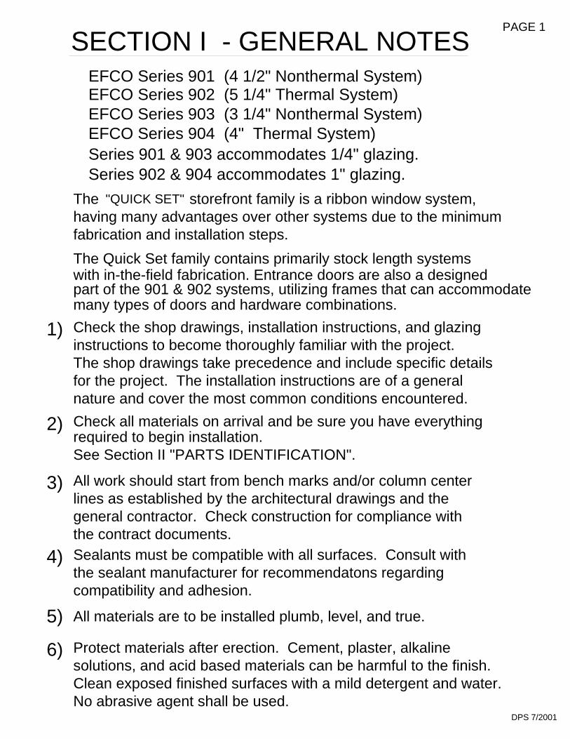
many types of doors and hardware combinations.part of the 901 & 902 systems, utilizing frames that can accommodate
1)
3)
4)
6)
Clean exposed finished surfaces with a mild detergent and water.No abrasive agent shall be used.
DPS 7/2001
Sealants must be compatible with all surfaces. Consult with
compatibility and adhesion.
All materials are to be installed plumb, level, and true.
Protect materials after erection. Cement, plaster, alkalinesolutions, and acid based materials can be harmful to the finish.
lines as established by the architectural drawings and thegeneral contractor. Check construction for compliance withthe contract documents.
the sealant manufacturer for recommendatons regarding
EFCO Series 904 (4" Thermal System)
Check the shop drawings, installation instructions, and glazing
The shop drawings take precedence and include specific detailsfor the project. The installation instructions are of a generalnature and cover the most common conditions encountered.
required to begin installation.Check all materials on arrival and be sure you have everything
See Section II "PARTS IDENTIFICATION".
All work should start from bench marks and/or column center
instructions to become thoroughly familiar with the project.
EFCO Series 901 (4 1/2" Nonthermal System)EFCO Series 902 (5 1/4" Thermal System)EFCO Series 903 (3 1/4" Nonthermal System)
SECTION I - GENERAL NOTES PAGE 1
The storefront family is a ribbon window system,
fabrication and installation steps.
The Quick Set family contains primarily stock length systemswith in-the-field fabrication. Entrance doors are also a designed
Series 901 & 903 accommodates 1/4" glazing.
having many advantages over other systems due to the minimum
Series 902 & 904 accommodates 1" glazing.
"QUICK SET"

DOOR HEADER 9933
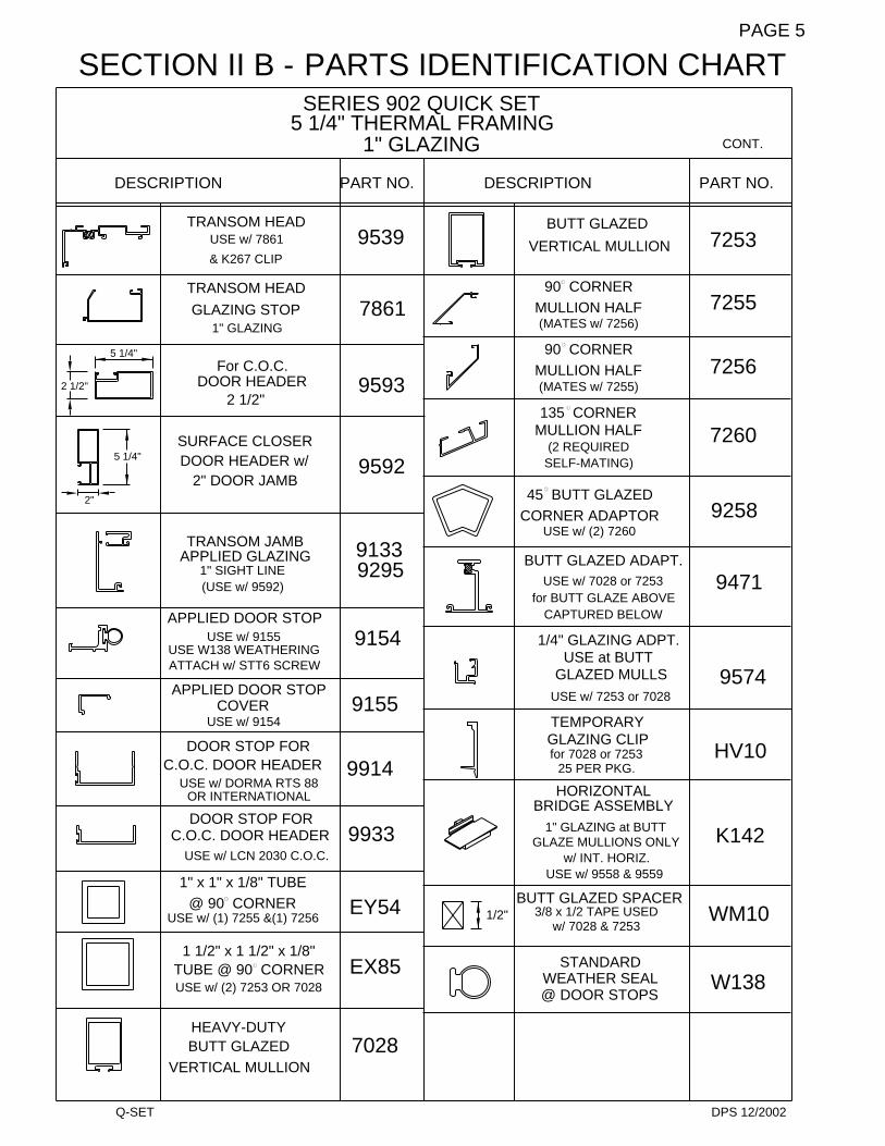
BUTT GLAZED
USE w/ LCN 2030 C.O.C.
VERTICAL MULLION 7028
DPS 7/2001
DOOR STOP FOR C.O.C.
DOOR STOP FOR C.O.C.
OR INTERNATIONAL C.O.C.USE w/ DORMA RTS 88 C.O.C.
VERTICAL MULLION
2 1/2" DOOR HEADER
APPLIED DOOR STOP
APPLIED DOOR STOP
USE w/ 9155. USE W138
ATTACH w/ STT6 SCREW
USE 9914 STOP/COVEROR 9933 STOP/COVER
USE w/ 9154/9155 STOP
PARTS IDENTIFICATION CHARTSERIES 901 QUICK SET
2 COLOR COVER
SLIDE on FACE
MULLION STOP2 REQUIRED w/ 9578 - 9579
CAPTURED VERT.
GLAZING STOP
HEAVY-DUTY
HEAD/SILL CANUSE w/ 9479
USE w/ 8593
USE w/ 9578
2 PC. JAMB
CAPTURED2 PC JAMB
9579 VERT. FACE8593 2 pc. JAMB
VERT. MULLIONCAPTURED
USE w/ 9578FACE
9571
8589
8593
DOOR HEADER
WEATHER STRIP
USE w/ 9154COVER
4 1/2"9580
2 1/
2"
9578
9579
4 1/
2"
for C.O.C.
1/4" GLAZING
SURFACE CLOSERDOOR HEADER W/2" DOOR JAMB or
2"
4 1/2" NONTHERMAL FRAMING
CAPTURED MULLION/
HORIZONTAL STOP
INTERMEDIATEHORIZONTAL FACE
INTERMEDIATE
USE 9587 & 9565
HEAD AND SILL
USE 9485 CAN FILLER
USE w/ 9469
INTERMEDIATE
JAMB BACK
USE w/ 9469
HORIZONTAL
CAN FILLERUSE w/ 9479
4 1/2" CAN
DESCRIPTION
9587
9565
9469
2 REQUIRED
TRANSOM HEAD
USE 7861 STOP
GLAZING STOP
TRANSOM HEAD
1/4" GLAZING
MULLION HALF90 CORNER
MATES w/ 7255
MULLION HALF135 CORNER
1/4" GLAZING
9485
9479
PART NO.
BUTT GLAZED
90 CORNER
MATES w/ 7256MULLION HALF
DESCRIPTION
SECTION II A -
7861
9914
9154
9155
9598
9597
9472
7256
7260
7253
7255
PART NO.
PAGE 2
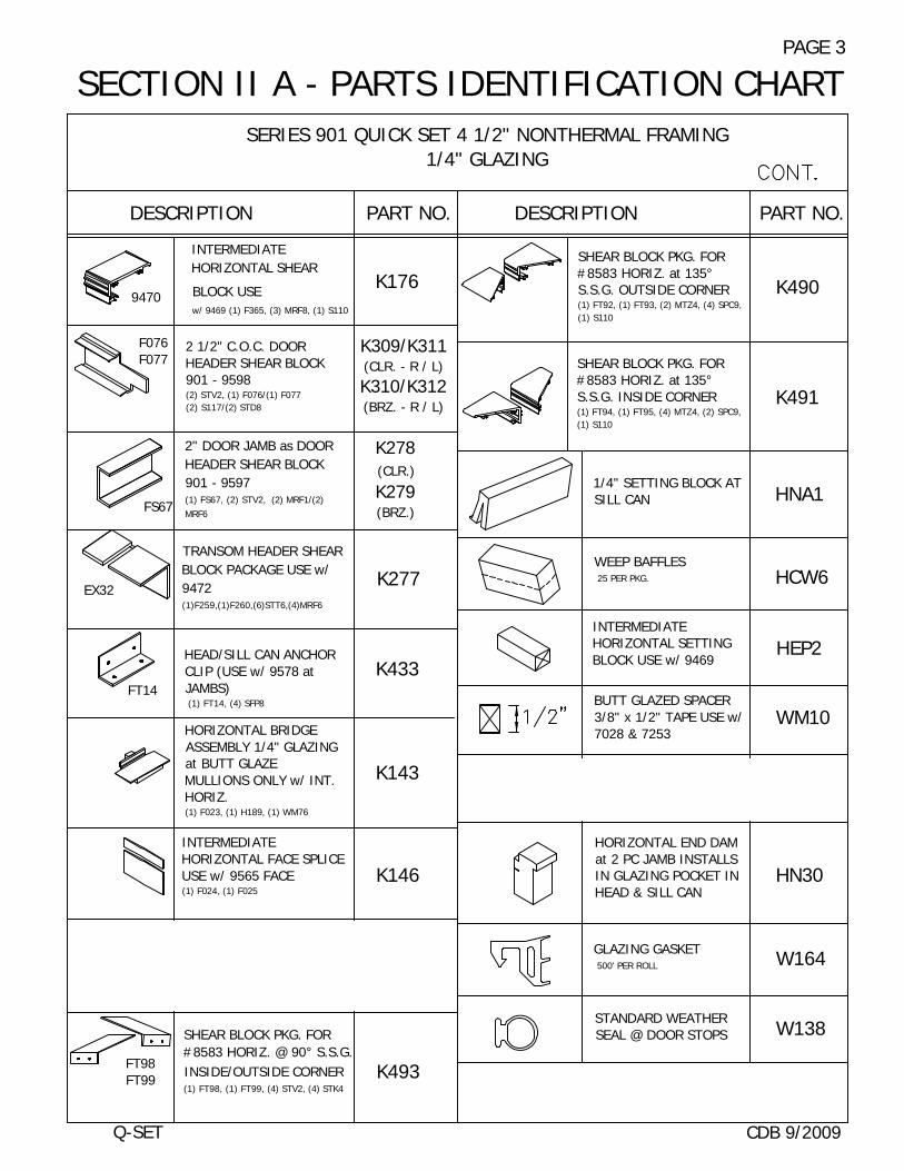
SERIES 901 QUICK SET 4 1/2" NONTHERMAL FRAMING1/4" GLAZING
SHEAR BLOCK PKG. FOR#8583 HORIZ. at 135°S.S.G. OUTSIDE CORNER(1) FT92, (1) FT93, (2) MTZ4, (4) SPC9,(1) S110
SHEAR BLOCK PKG. FOR#8583 HORIZ. at 135°S.S.G. INSIDE CORNER(1) FT94, (1) FT95, (4) MTZ4, (2) SPC9,(1) S110
DESCRIPTION PART NO. DESCRIPTION PART NO.
K490
K491
HNA11/4" SETTING BLOCK ATSILL CAN
WEEP BAFFLES 25 PER PKG. HCW6
INTERMEDIATEHORIZONTAL SETTINGBLOCK USE w/ 9469
HEP2
BUTT GLAZED SPACER3/8" x 1/2" TAPE USE w/7028 & 7253
WM10
TEMPORARY GLAZINGCLIP USE w/ 7028 & 7253 HV11
SECTION II A - PARTS IDENTIFICATION CHARTPAGE 3
HORIZONTAL END DAMat 2 PC JAMB INSTALLSIN GLAZING POCKET INHEAD & SILL CAN
HN30
W164
W138
GLAZING GASKET 500' PER ROLL
STANDARD WEATHERSEAL @ DOOR STOPS
INTERMEDIATEHORIZONTAL SHEAR
BLOCK USEw/ 9469 (1) F365, (3) MRF8, (1) S110
9470K176
F076F077
2 1/2" C.O.C. DOORHEADER SHEAR BLOCK901 - 9598(2) STV2, (1) F076/(1) F077(2) S117/(2) STD8
K309/K311(CLR. - R / L)
K310/K312(BRZ. - R / L)
FS67
2" DOOR JAMB as DOORHEADER SHEAR BLOCK901 - 9597(1) FS67, (2) STV2, (2) MRF1/(2)MRF6
K278(CLR.)
K279(BRZ.)
TRANSOM HEADER SHEARBLOCK PACKAGE USE w/9472(1)F259,(1)F260,(6)STT6,(4)MRF6
K277
HEAD/SILL CAN ANCHORCLIP (USE w/ 9578 atJAMBS) (1) FT14, (4) SFP8
HORIZONTAL BRIDGEASSEMBLY 1/4" GLAZINGat BUTT GLAZEMULLIONS ONLY w/ INT.HORIZ.(1) F023, (1) H189, (1) WM76
INTERMEDIATEHORIZONTAL FACE SPLICEUSE w/ 9565 FACE(1) F024, (1) F025
K433
K143
K146
HEAD/SILL SPLICE for 901(USE w/ 9479)25 PER PACKAGE (1) F014, (1) WM96,
(1) WM01
SHEAR BLOCK PKG. FOR#8583 HORIZ. @ 90° S.S.G.INSIDE/OUTSIDE CORNER(1) FT98, (1) FT99, (4) STV2, (4) STK4
FT98FT99
7885
FT14
EX32
Q-SET CDB 9/2009
K376
K493

1" GLAZING
SERIES 902 QUICK SET5 1/4" THERMAL FRAMING
PARTS IDENTIFICATION CHART
GLAZING STOP1/4" GLASS W/ 8583/8500
HEAD CAN FACE 9847
GLAZING STOP
8499 FACE & 9587 STOPUSE K176 S.B.
INTERMEDIATEOPT. H.D. HORIZONTAL
GLAZING STOPHORIZONTAL
H.D. INTERMEDIATE
USE w/ 8583
USE w/ 8500
OPT. INTERMEDIATEHORIZONTAL 9541
9587
8500
USE w/ 8499, 8584, 9541
INTERMEDIATEHORIZONTAL FACE
USE w/ 8583 or 8500
INTERMEDIATEHORIZONTAL
HORIZONTALINTERMEDIATE
USE w/ 9845
8499
8584
8583
HEAD/SILL CAN 98459846 or 9847 FACE
USE 9485 CAN FILLER
THERMAL STRUTHEAD and SILL
5 1/4" CANUSE 9485 CAN FILLER
OUTSIDE GLAZED
OUTSIDE GLAZED
USE w/ 9845
SILL CAN FACE 9846
1G66
CAN FILLERUSE w/ 9484, 9845 OR 1G66
OUTSIDE GLAZED
HEAD and SILL5 1/4" CAN
USE 9485 CAN FILLER
DESCRIPTION
9484
9485
PART NO.
SECTION II B -
BAH 4/2005
92601/2" GLAZING ADPT.
2 COLOR COVER(9484 HEAD/SILL CAN)
at 1" GLAZING POCKETS
at 1" GLAZING POCKETS
1/4" GLAZING ADPT.
9570
9261
9578 & 1G41USE w/
(2) 9580 STOPS
MULLION & JAMB STOPCAPTURED VERTICAL
for 1/4" GLASS
'I' BAR (2) COLORCAPTURED VERTICAL
USE WITH
OPTIONAL
9542
1G41
2 PC JAMB
USE w/ 9578
9578 & 8594
2 PC JAMBGLASS STOP
SLIDE on FACE
CAPTURED
2 REQUIRED w/MULLION STOP
9578 & 1G41
& 8589
USE w/
8589
8594
9580
USE w/ 9578
CAPTURED MULLIONSLIDE ON FACE
MULLION BACK
USE w/ 9576 & 8594
CAPTURED
DESCRIPTION
9578
9576
PART NO.
PAGE 4
VERTICAL MULLION
DPS 12/2002
1" GLAZING
C.O.C. DOOR HEADERUSE w/ DORMA RTS 88
OR INTERNATIONAL
DOOR STOP FOR
DOOR STOP FOR
USE w/ LCN 2030 C.O.C.
C.O.C. DOOR HEADER
ATTACH w/ STT6 SCREWUSE W138 WEATHERING
APPLIED DOOR STOP
APPLIED DOOR STOP
USE w/ (2) 7253 OR 7028
1 1/2" x 1 1/2" x 1/8"
USE w/ (1) 7255 &(1) 7256
SURFACE CLOSERDOOR HEADER w/
APPLIED GLAZING
TUBE @ 90 CORNER
BUTT GLAZEDHEAVY-DUTY
1" x 1" x 1/8" TUBE@ 90 CORNER
USE w/ 9154
USE w/ 9155
COVER
2" DOOR JAMB
5 1/4"
2 1/2"
2"
For C.O.C.
1" SIGHT LINE(USE w/ 9592)
TRANSOM JAMB
DOOR HEADER
5 1/4"
2 1/2"
TRANSOM HEAD
GLAZING STOP1" GLAZING
& K267 CLIP
DESCRIPTION
TRANSOM HEADUSE w/ 7861
for BUTT GLAZE ABOVE
9933
1/2"
EX85
7028
EY54
STANDARDWEATHER SEAL@ DOOR STOPS
w/ INT. HORIZ.GLAZE MULLIONS ONLY
w/ 7028 & 72533/8 x 1/2 TAPE USED
BUTT GLAZED SPACER
USE w/ 9558 & 9559
9914
9154
9155
1" GLAZING at BUTT
BRIDGE ASSEMBLYHORIZONTAL
GLAZING CLIPfor 7028 or 7253
25 PER PKG.
TEMPORARY
USE at BUTTGLAZED MULLS
USE w/ 7253 or 7028
1/4" GLAZING ADPT.
CAPTURED BELOW
K142
W138
WM10
HV10
9574
MULLION HALF
92959133
9593
9592
USE w/ 7028 or 7253
BUTT GLAZED ADAPT.
USE w/ (2) 7260CORNER ADAPTOR45 BUTT GLAZED
SELF-MATING)(2 REQUIRED
135 CORNER
(MATES w/ 7255)
MULLION HALF
DESCRIPTION
7861
9539
PART NO.
(MATES w/ 7256)
90 CORNER
90 CORNER
MULLION HALF
BUTT GLAZED
VERTICAL MULLION
7256
9471
9258
7260
7255
PART NO.
CONT.
7253
SERIES 902 QUICK SET5 1/4" THERMAL FRAMING
SECTION II B - PARTS IDENTIFICATION CHARTPAGE 5
Q-SET

SECTION II B - PARTS IDENTIFICATION CHARTPAGE 6
SERIES 902 QUICK SET 5 1/4" THERMAL FRAMING1" GLAZING
DESCRIPTION PART NO. DESCRIPTION PART NO.
INTERMEDIATE HORIZONTALSHEAR BLOCK USE w/ 8583or 8500(1) F365, (3) MRF8, (1) S110
K176
HEAD/SILL CAN ANCHORCLIP USE w/ 9578 at JAMBS
(1) FT14, (4) SFP8FT14
K433
TRANSOM HEADER SHEARBLOCK PACKAGE USE w/ 9539
(1) F344, (1) F345, (8) STT6, (4) MRF6K267
EX32
FS67
2" DOOR JAMB as DOORHEADER SHEAR BLOCK 902- 9592(1) FS67, (2) STV2, (2) MRF1/(2) MRF6
K278(CLR.)
K279(BRZ.)
2 1/2" - C.O.C. DOOR HEADERSHEAR BLOCK 902 - 9593(1) F078, (1) F079, (4) STV2, (4) S117/(4)STD8
F078F079
K273(CLR.)
K274(BRZ.)
SHEAR BLOCK PKG. FOR#8583 HORIZ. at 135°S.S.G. OUTSIDE CORNER (1) FT92, (1) FT93, (2) MTZ4, (4) SPC9,(1) S110
K490
SHEAR BLOCK PKG. FOR#8583 HORIZ. at 135°S.S.G. INSIDE CORNER(1) FT94, (1) FT95, (4) MTZ4, (2) SPC9,(1) S110
K491
K493
SHEAR BLOCK PKG. FOR#8583 HORIZ. @ 90° S.S.G.INSIDE/OUTSIDE CORNER (1) FT98, (1) FT99, (4) STV2, (4) STK4
FT98FT99
1" SETTING BLOCK forINTERMEDIATE HORIZONTAL HN90
HN31HORIZONTAL END DAM for1" GLZ. @ 2 PC. JAMB
1" SETTING BLOCK at SILLCAN25 PER PACKAGE HN33
HEAD/SILL CAN SPLICE
(USE WITH 9484)25 PER PACKAGE (1) F015, (1) WM96,
(1) WM01
K377
HEAD/SILL CAN SPLICE
(USE WITH 1G66)(1) FU12, (1) WM96
K917
K375
OUTSIDE GLAZEDHEAD/SILL SPLICE (USE
WITH 9845)(1) F001, (1) WM96
WEEP BAFFLESHCW6
K460
INTERMEDIATEHORIZONTAL FACE
SPLICE USE w/ 8499(2) FT49
HWD1WATER DEFLECTOR @ INT.HORIZONTAL
GLAZING GASKET500' PER ROLL W164
FU081" SETTING BLOCK at1G66 SILL CAN25 PER PACKAGE
SETTING BLOCK for 9592JAMB when used asTRANSOM
HN32
CDB 9/2009

DPS 7/2001
SERIES 903 QUICK SET
CAPTURED VERTICAL
2 COLOR COVER
USE w/ 9476
at HEAD and SILL CAN
2 PC JAMB
USE W/ 9575
2 PC JAMBGLASS STOP
USE w/ 9575 & 8593
SLIDE on FACE
8590
9572
8593
MULLION FACE
MULLION STOPCAPTURED
USE W/ 9575
9579 VERT. FACE
CAPTURED
MULLION / JAMB
USE (2) w/ 9575 & 9579
8593 2 pc. JAMB FACE
BACK
9579
9577
9575
1/4" GLAZING3 1/4" NONTHERMAL FRAMING
USE w/ 9586
USE W/ 9586
INTERMEDIATE
INTERMEDIATEHORIZONTAL
HORIZONTAL FACEINTERMEDIATE
USE W/ 9565 & 9566
HORIZONTAL STOP
9565
9566
9586
USE 9478 FILLER
CAN FILLERUSE w/ 9476
HEAD and SILL3 1/4" CAN
DESCRIPTION
9478
9476
PART NO.
MULLION HALF
MULLION HALF
VERTICAL MULLION
135 CORNER
(2 REQUIRED)
(2 REQUIRED)
90 CORNER
9562
9563
VERTICAL MULLIONBUTT GLAZED
BUTT GLAZEDHEAVY-DUTY
DESCRIPTION
9558
9559
PART NO.
PARTS IDENTIFICATION CHARTSECTION II C -PAGE 7

SECTION II C - PARTS IDENTIFICATION CHART
SERIES 903 QUICK SET 3 1/4" NONTHERMAL FRAMING1/4" GLAZING
DESCRIPTION PART NO. PART NO.
CONT.
PAGE 8
1/4" SETTING BLOCKUSE w/ 9476
HORIZONTAL END DAMfor 1/4" GLZ. at 2 PC.JAMB INSTALLS inGLAZING POCKET in HEADand SILL CAN
HN30
HCW6WEEP BAFFLES25 PER PKG.
GLAZING GASKET500' PER ROLL
INTERMEDIATEHORIZONTAL SETTINGBLOCK USE w/ 9586 H191
WM10BUTT GLAZED SPACER 3/8"x 1/2" TAPE USE w/ 9558and 9559
TEMPORARY GLAZINGCLIP USE w/ 9558 and9559
HV11K434
ANCHOR CLIP @ PERIMETER
JAMBS(1) FT15, (4) SFP8
HORIZONTAL BRIDGEASSEMBLY 1/4" GLAZING atBUTT GLAZE MULLIONS ONLYw/ INT. HORIZ. USE w/ 9558and 9559(1) F023, (1) H189, (1) WM76
K143
K146
INTERMEDIATEHORIZONTAL FACE
SPLICE USE w/ 9565 FACE(1) F024, (1) F025
HEAD/SILL CAN SPLICEUSE w/ 9476 25 PER PACKAGE
K378
K434HEAD/SILL CAN ANCHORCLIP USE w/ 9575 at JAMB(1) FT15, (4) SFP8
INTERMEDIATE HORIZONTALSHEAR BLOCK USE w/ 958 (1) F021, (3) MRF7 K141
CDB 9/2009
DESCRIPTION
FT15
7885
HNA2
W164

USE w/ (2) 9558 or 9559TUBE @ 90 CORNER
1 1/2"x1 1/2"x1/8"
BUTT GLAZED
CAPTURED BELOW
USE w/ 9558 or 9559
ADAPTOR
for BUTT GLAZED ABOVE
at 1" GLAZING POCKETS1/2" GLAZING ADPT.
2 PC JAMBSLIDE on FACE
(USE w/ 9575)
USE w/ 9575
GLASS STOP2 PC JAMB
at 90 CORNER
USE w/ (2) 9562
45 BUTT GLAZEDCORNER ADAPTOR
1" x 1" x 1/8" TUBE
USE w/ (2) 9563@ 90 CORNER
MULLION HALF
135 CORNER
(2 REQUIRED)MULLION HALF
(2 REQUIRED)
VERTICAL MULLION
90 CORNER
BUTT GLAZEDVERTICAL MULLION
BUTT GLAZEDHEAVY-DUTY
PARTS IDENTIFICATION CHART
1/4" GLAZING ADPT.at 1" GLAZING POCKETS
USE w/ 9564
MULLION / JAMB
9576 VERT. FACEBACK
INTERMEDIATE
USE w/ 9564
MULLION FACEUSE w/ 9575
CAPTURED VERT.
8594 2 pc. JAMB FACE
CAPTURED VERT.
HORIZONTAL FACE
MULLION STOPUSE (2) w/ 9575
CAPTURED VERT.9577
9576
9575
9565
1" GLAZING
USE w/ 8716 CAN
OUTSIDE GLAZEDSILL CAN
USE 9478 CAN FILLERHEAD / SILL CAN
OUTSIDE GLAZED
CAN FILLERUSE w/ 9477 & 9468
FLAT BOTTOM
DESCRIPTION
HEAD and SILL CAN
USE 9478 CAN FILLER
HEAD and SILL CANCONCEALED WEEPUSE 9478 CAN FILLER
HEAD CANOUTSIDE GLAZED
USE w/ 8716 CAN
INTERMEDIATE
INTERMEDIATE
USE w/ 9565 & 9566HORIZONTAL
HORIZONTAL STOP
8716
9847
9566
9564
9846
PART NO.
9468
9478
9477
DESCRIPTION
SECTION II D -
4" THERMAL FRAMINGSERIES 904 QUICK SET
9258
9261
DPS 7/2001
9471
9260
EX85
9562
EY54
9558
9563
8590
9559
PART NO.
8594
PAGE 9

SECTION II D - PARTS IDENTIFICATION CHARTPAGE 10
CONT.
PART NO.DESCRIPTIONPART NO.DESCRIPTION
INTERMEDIATE HORIZONTAL
SHEAR BLOCK USE w/ 9564(1) F021, (3) MRF7
K141WATER DEFLECTOR @INT. HORIZONTAL HWD1
HN341" SETTING BLOCK atSILL CAN
GLAZING GASKET500' PER ROLL W164
WM10BUTT GLAZED SPACER
3/8" x 1/2" TAPE USE w/7028 & 7253
TEMPORARY GLAZINGCLIP for 7028 or 725325 PER PKG. HV10
1/4" GLAZING ADPT. atBUTT GLAZED MULL USE w/9558 or 9559
9574
K375
OUTSIDE GLAZED HEAD/SILLSPLICE USE w/ 8716 O.G.CAN(1) F001, (1) WM96
HEAD/SILL CAN SPLICE USEw/ 9477 & 9468 25 PERPACKAGE(1) F017, (1) WM96, (1) WM01
K379
HORIZONTAL BRIDGEASSEMBLY 1" GLAZING atBUTT GLAZE MULLIONSONLY w/ INT. HORIZ. USE w/9564 (1) F022, (1) H189, (1) WM76
K142
K146INTERMEDIATE HORIZONTALFACE SPLICE USE w/ 9565FACE (1) F024, (1) F025
ANCHOR CLIP @ PERIMETERJAMBS(1) FT15, (4) SFP8
K434
HN31
HORIZONTAL END DAM for 1"GLZ. at 2 PC. JAMB INSTALLSin GLAZING POCKET in HEADand SILL CAN
WEEP BAFFLES 25 PER PKG. HCW6
HN90
1" SETTING BLOCK forINTERMEDIATEHORIZONTAL
SERIES 904 QUICK SET 4" THERMALFRAMING 1" GLAZING
CDB 9/2009
1/2"

HORIZONTAL
.590
VERTICALS
1.625
BUTT GLAZED
TOP OF
7253
7028
JDA 10/2001
OR 8593
SECTION III A - FABRICATION DRILLING TEMPLATE - 901/902 INTERMEDIATE HORIZONTAL
5/8"
NO
TC
HA
T V
ER
TIC
ALS
8499
AT
JA
MB
1" N
OT
CH
1.00
0
FRONT OF MULLION
FRONT OF MULLION
901/902 SYSTEMS
903/904 SYSTEMS
1/2" F.H.#10-24x
(S110)
8583
1.625
.590NOTE: OFFSET
.062
8594
TOP OFHORIZONTAL
9578
.312
.750
(9470)K176
.149 DIA. (#25 DRILL)FOR #10-24 x 1 3/4" P.H.S.M.S.(3) MRF8
OR 95799576
JAMBS2 PC. CAPTURED
VERTICALS
PAGE 11
.625

PAGE 12
BUTT GLAZED
.475
VERTICALS
9559
9558
HORIZONTAL
.875
TOP OF
CAPTUREDVERTICALS
DRILLING TEMPLATE - 903/904 INTERMEDIATE HORIZONTAL
9586/9564
9565
NOTE: OFFSET
1.00
0
8594OR 8593
.062
.475
HORIZONTAL
FRONT OF MULLION
FRONT OF MULLION901/902 SYSTEMS
903/904 SYSTEMS
(9567)K141
.313
.500
OR 9576
.149 DIA. (#25 DRILL)
.875TOP OF
9575 9579
SECTION III B - FABRICATION
2 PC. JAMB
FOR #10-24 x 1 3/4" P.H.S.M.S.(3) MRF8
JDA 10/2001
.625

includes 2 color covers, installed prior to weeping and anchoring.
NOTE: Sill cans with riser legs are bottom weeped and sill cans with flat
903/904
bottoms are face weeped.
HOLE IN BOTTOM
See Fig. 3 on Page 14.
HCW6
[FIG. 2]
HCW6901/902
HOLE IN FACE
DPS 7/2001
INCLUDES CAPTURED AND BUTT
the center of the nearest lite and adjust cut lengths accordingly.
NOTE: Expansion/splice joints are required in elevations that exceed
Measure the opening to determine the cut length of the head
JAMB
"2" color covers that are being used.
and sill frame components. Allow for shims if applicable.
Cut head and sill cans to frame width. This includes any
20 FT. TYPICAL
HEAD & SILL LENGTH
20’-0" in width. Plan for expansion/splice joints to fall at
Drill 1/4" weep holes in sill can 6" from jambs and 48" oncenter or if the length is less than 48", drill (1) per lite. This
STEP 3)
JAMB
SHIM
STEP 2)
OPT.1/4"
[FIG. 1]EXPANSION/SPLICEJOINT
SHIM20 FT. MAXIMUM
1/2"OPT.1/4"
SECTION III C - FABRICATION
STEP 1)GLAZED MULLION SYSTEMS
PAGE 13
HEAD AND SILL CAN

FR
AM
E D
IM.
[FIG. 4]
FRAME DIM.
12" 1/2"
135
1/2"
DPS 7/2001
EXPANSION.OUT OF POSITION WITH THERMALPREVENT COVER FROM WALKINGCRIMP THIS LEG SLIGHTLY TO
This includes 2 color covers installed prior to anchoring. Head and sill cans are mitered for inside or outside corners.
STEP 4) 90 AND 135 CORNER FABRICATION
NOTE: An expansion/splice joint located 12" from the miter joint is
TAP LIGHTLYTO SNAP IN PLACE
THRU COVER AND SILLDRILL 1/4" DIA. WEEP HOLES
OPTIONAL SEAL(LEAVE 1/4" SPACE
See Fig. 4 below.
AT WEEP HOLES)
recommended to reduce expansion at the miter joint.
1/2"
12"
901/2" 12"
HOOK COVER OVER LEG
BEHIND COVER LEG.LOCATE PRIMARY SEAL
[FIG. 3]
12"
FRAME DIM
.
(CONT.)
PAGE 14
HEAD AND SILL CAN SECTION III C - FABRICATION
GLAZED MULLION SYSTEMSINCLUDES CAPTURED AND BUTT
TOP VIEW OF THE SILL CAN AT
90˚ OUTSIDE AND 135˚ INSIDE CORNERS.

The end dam must seal to the web of the jamb member (not shown).
[FIG. 5]
STEP 5) Weep Baffle Installation
Tool sealant over the inside edges of the dam to insure a water seal.Install the dams in the ends of the head and sill flush with the end.
[FIG. 6]
1/2 HCW6
STEP 6) End Dam Installation
WEEP HOLE
See Fig. 6.
SEALANT
BAFFLE
DPS 7/2001
HN31 - 1" GLAZING POCKET [902 & 904]HN30 - 1/4" GLAZING POCKET [901 & 903]
SEALANT
WEEP HOLE
BAFFLE
PAGE 15
HEAD AND SILL CAN SECTION III C - FABRICATION
(CONT.)
APPLY A SMALL AMOUNT OF SILICONE TYPE
SEALANT TO THE BAFFLES THAT WILL
STRADDLE THE DRILLED WEEP HOLE, AND
LOCATE THEM OVER THE WEEP HOLES AS
SHOWN. DO NOT PLUG THE WEEP HOLES
WITH SEALANT. CUT HCW6 IN HALF TO
CREATE CORRECT SIZE BAFFLES.
SEE FIG. 17 ON PAGE 23.

(Head and sill cans run through. Can fillers run mullion to mullion,and mullion to jamb.)
1"
CL
1"
MULLION CENTER LINE
2"
CAN FILLERCUT LENGTH
CAN FILLER LENGTH
CENTER LINEMULLION
CL
[FIG. 8]
CAN FILLER LENGTH2"
CENTER LINECL
MULLION
2"
DPS 7/2001
CL
2"
Step 1) Determine center lines of each vertical mullion.
to center line of first mullion minus 1 1/2".
and mullion to jamb.)
1) CAN FILLER CUT LENGTHS
SECTION III D - FABRICATION
to center line of first mullion minus 2".
Step 1) Determine center lines of each vertical mullion.2) CAN FILLER CUT LENGTHS
Step 3) Mullion to mullion cut length = Center line to center line
Step 2) Jamb to first mullion cut length = End of head/sill can
(Head and sill cans run through. Can fillers run mullion to mullion,
Step 2) Jamb to first mullion cut length = End of head/sill can
Step 3) Mullion to mullion cut length = Center line to center line
MULLION 1"
LC
minus 2".
CENTER LINE2"
1" CAN FILLERCUT LENGTH
minus 1".
CAN FILLER LENGTH
MULLION MULLION
(BUTT GLAZED SYSTEMS)
CENTER LINECL
[FIG. 7]
CENTER LINECL
1" CAN FILLER LENGTH 1"
CL
1"
HEAD AND SILL CAN FILLER
(CAPTURED MULLION SYSTEMS)
PAGE 16

IN CHART A.THIS CLEARANCE IS INCLUDED IN THE CUT LENGTH FORMULAS1/4" CLEARANCE +/- IS REQUIRED WHEN USING THESE CANS.THE PERIMETER FASTENER HEAD. THEREFORE, AN ADDITIONALHEAD AND SILL CANS, 9476, 9477, AND 1G66, DO NOT HAVE A RELIEF FOR
If 2 color covers are used at the head and sill, the cut length of the verticalmullion face member is D.L.O. minus 1/8".
*
903/904901/902
902/904901/903
NOTE:
VERTICAL MULLION &
GLASS STOPS
FACE MEMBERS2 PC JAMB
[CHART "A"]
4 1/2"-5 1/4"3 1/4" - 4"
5 1/4" - 4"
4 1/2"-3 1/4"
9577 & 85909580 & 8589
9576 & 8594
9579 & 8593
D.L.O.
D.L.O.
JDA 4/2002
*
Cut the captured mullion/jamb backs to the lengths shown in chart A below. This will allow 1/8" clearance inside the head can.
SECTION III E - FABRICATION
Cut the captured mullion face and the 2 pc. jamb face to the D.L.O. height.
Cut the butt glazed mullions to the lengths shown in chart A below.This will allow 1/4" minimum clearance inside the head can.
904
903
SERIES
901
902
STEP 1)
I-BAR MULLION
BUTT GLAZED MULLIONS
CAPTURED VERTICAL
CAPTURED VERTICAL
BUTT GLAZED MULLIONS
MULLION BACK
CAPTURED VERTICAL
MULLION BACK
BUTT GLAZED MULLIONS
BUTT GLAZED MULLIONS
CAPTURED VERTICAL
BUTT GLAZED MULLIONS
CAPTURED VERTICAL
BUTT GLAZED MULLIONS
CAPTURED VERTICAL
MULLION BACK
MULLION BACK
MULLION BACK
DESCRIPTION
7253/7028
4"
9477
9477
3 1/4"
1G66
1G66
9476
9476
9558/9559
9558/9559
9575
9575
NOTCHING REQ.
9558/9559
7253/7028
1G41
9575
HEAD/SILL
9484 or 9845
9484 or 9845
CAN #DEPTH
4 1/2"
5 1/4"
9479
9479
SYSTEMMULL #
7253/7028
9578
9578
D.L.O. + 3 1/4"
D.L.O. + 3 1/2"
D.L.O. + 3 1/4"
D.L.O. + 3 3/8"
D.L.O. + 3 1/2"
D.L.O. + 3 1/8"
D.L.O. + 3 1/4"
D.L.O. + 3 1/8"
D.L.O. + 4 1/8"
D.L.O. + 4 1/4"
D.L.O. + 3 3/4"
D.L.O. + 3 5/8"
CUT LENGTHS
*
VERTICAL INTERMEDIATE AND 2 PIECE JAMB (BUTT GLAZED and CAPTURED MULLION SYSTEMS)
PAGE 17
9484 or 9845 1G41NOTCHING REQ. I-BAR MULLION
CAPTURED VERTICAL D.L.O. + 3 11/16"
9468 or 8716
9468 or 8716
Quick Set

TOP OF MULLION FACE
1/8"
1/4" [FIG. 9]
DPS 7/2001
STEP 2)Fig. 9 below. This prep is for ease of installation of the jamb andvertical mullion.
9579 or 9576
8593
8594
Notch the top of the mullion and jamb face 1/8" x 1/4" as shown in
PAGE 18
(CONT.)
SECTION III E - FABRICATIONVERTICAL INTERMEDIATE AND 2 PIECE JAMB
(BUTT GLAZED and CAPTURED MULLION SYSTEMS)

MULLIONFACE
[FIG. 11]
JAMB FACE
DPS 7/2001
JAMB BACK
attachment screws using the drilling templates on pages 11 & 12.If horizontal intermediates are incorporated, drill for shear block
Slide the mullion face onto the mullion back as shown in Fig. 11.
Typical drilled members are shown in Fig. 10 below.Jamb members will have preps on one side only.
Cut length for the vertical mullion and jamb face is similar.Please refer to chart ’A’ on page 17 and notching required
See Section IV B for installation procedures.
MULLION BACK
STEP 5)
shown on page 18.
STEP 4)
9578
[FIG. 10]
9575
STEP 3)
PAGE 19
(CONT.)
SECTION III E - FABRICATIONVERTICAL INTERMEDIATE AND 2 PIECE JAMB
(BUTT GLAZED and CAPTURED MULLION SYSTEMS)

[FIG. 12]
TO
P O
F M
ULL
ION
FA
CE
BAH 4/2005
1/8"
NOTCHING AT TOP OF MULLION
2"
9547
3" (VARIES)
9546
1/4"
3/32"
to all solid vertical intermediate mullions with 1" glazing.The 2" dimension taken from the exterior face will be applicable
PAGE 20
STEP 1)
SECTION III F - FABRICATION
STEP 2)
STEP 3)as shown in Fig. 12 below.
INSULBAR INTERMEDIATE VERTICAL
Notch the top of the mullion face 1/8" x 1/4" as shown in Fig. 12.This prep is for ease of installation of the vertical mullion.
Cut the thermal strut vertical mullion to the length shown in [CHART "A"]
Notch the TOP of the mullion to leave the appropriate portion
on page 17 (SECTION III E - FABRICATION).
1 1/
2" @
#87
16 C
AN
1 5/
32"
@ #
9468
& #
9477
CA
N
1 17
/32"
@ #
9484
& #
9485
CA
N
1 5/
8" @
1G
66 I-
BA
R C
AN
{S90
2{ S
904
COMPOSITE #1G41 SHOWNOTHER MULLIONS ARE SIMILAR
Quick Set

Notch the BOTTOM of the mullion to leave the appropriate portionas shown in Fig. 13 below.
SECTION III F - FABRICATION
NOTCHING AT THE BOTTOM OF THE MULLION[FIG. 13]
BO
TT
OM
OF
MU
LLIO
N F
AC
E
STEP 4)
1 29
/32"
@ 1
G66
I-B
AR
CA
N
2 3/
16"
@ #
9484
& #
9485
CA
N
3" (VARIES)
BAH 4/2005
COMPOSITE #1G41 SHOWN
9546 9547
THERMAL STRUT INTERMEDIATE VERTICAL (CONT.)
PAGE 21
2"
The 2" dimension taken from the exterior face will be applicableto all solid vertical intermediate mullion with 1" glazing.
1 25
/32"
@ #
9468
& #
9477
CA
N
{ {S90
4
S90
2
2 3/
16"
@ #
8716
CA
N
OTHER MULLIONS ARE SIMILAR
Quick Set

CAPTURED VERTICALS5/8" NOTCH AT
2 PC. JAMBS ONLY1" NOTCH AT
8583
.542
DPS 7/2001
NO
TC
H
SECTION III G - FABRICATION
HORIZONTAL CUT LENGTH FORMULAS
CUT LENGTH = EXTERIOR D.L.O. {at BUTT GLAZED MULLION to
CUT LENGTH = EXTERIOR D.L.O. + 1 1/4" {at CAPTURED VERTICAL MULLION to
CUT LENGTH = EXTERIOR D.L.O. + 1 5/8" {at 2 pc. JAMB to
CUT LENGTH = EXTERIOR D.L.O. + 1" {at 2 pc. JAMB to BUTT GLAZED MULLION
NO
TC
H
5/8" x 7/32" NOTCH IS REQUIRED AT CAPTURED VERTICALS ONLY.
1" x 7/32" NOTCH IS REQUIRED AT 2 PC. JAMBS ONLY.
5/8"
LO
NG
**
1" L
ON
G
CAPTURED VERTICAL MULLION
PLEASE REFERENCE PAGE 35 FIG. 36.
[Fig. 14]
#10-24x
AT
VE
RT
ICA
LS
9469 SIMILAR8583 SHOWN
.344 (11/32") DRILLBOTH ENDS
AT
JA
MB
1/2" F.H.(S110)
CAPTURED VERTICAL MULLION
BUTT GLAZED MULLION
[Fig. 15]
INTERMEDIATE HORIZONTAL
PAGE 22
THE FOLLOWING PREPS APPLY TO 902 AND 901 ONLY.SYSTEMS 903 AND 904 HAVE A ’SNAP FIT’ TO THE SHEAR BLOCK AND DO NOT REQUIRE DRILL/SCREW ATTACHMENT OR NOTCHING.
7/32"1"

WEEP
DPS 7/2001
AMOUNT of SILICONE TYPE SEALANT.APPLY BAFFLES WITH a SMALL
on center or 2 per lite at quarter points. Install weep bafflesDrill 1/4" diameter weep holes in the horizontal face member at 48"
over holes with silicone. Do not plug weep holes with silicone.
[FIG. 18]
See Fig. 18 above.
STEP 3)
HOLES
8499 SIMILAR9565 SHOWN
(CONT.)
PAGE 23
D.L.O.
INTERMEDIATE HORIZONTAL
3/8"
INTERIOR
HORIZONTAL FACE LENGTH (15 ft. max.)
Weep baffles are cut from (1) HCW6, halved, to provide (2)2" x 3/8" x 1/2" weep baffles. See Fig. 17 below.
Due to the expansion characteristics of the aluminum face memberand also to maintain the 1/4" splice joint, 15 feet is therecommended cut length for the face member.
1/2"
2"
HCW6
5/8"
3/4"
NOTE:
STEP 2)
{
[FIG. 17]
48" O.C.
2" 1/2"
[FIG. 16]
1/4"
D.L.O.
Splice ONLY at center lines of vertical mullions.of 15’-0"). Allow 1/4" at splice joints for expansion.Cut horizontal face member to span 3 lites (or a maximum
SECTION III G - FABRICATION
See Fig. 16 below.
STEP 1)
D.L.O. 2" D.L.O.2" 2"

Figure the splice joint location to fall at the center line of a
INTERMEDIATE HORIZONTAL
CUT LENGTH FOR FACE MEMBER = 3 Lites - Not to exceed 15’
CUT LENGTH FOR GLASS STOP = D.L.O. MINUS 1/32".
NEAT APPEARANCECLEAN EXCESS FOR AFILL VOID WITH SILICONE
CENTER LINE OF VERTICAL MULLION
[FIG. 19]
EXPANSION JOINT
1/4"
vertical mullion, with respect to the 3 lite/15’ guideline.
SILICONE ONE END ONLY.SET SPLICE PLATES IN
STEP 4)
903 - 3 1/4"
904 - 4"
& DEPTHSYSTEM
901 - 4 1/2"
902 - 5 1/4"
INTERM. HORIZ.EXTRUSION NOS.
9586/9566/9565
9564/9566/9565
[CHART B]
9469/9587/9565
8583/8584/8499
K-141
K-141
REQUIREDSHEAR BLOCK
K-176
K-176
SECTION III G - FABRICATION
at BUTT GLAZE VERTICAL APPLICATIONS.
VERTICAL to VERTICAL - INTERIOR D.L.O.
DPS 7/2001
(Cont.)
PAGE 24

#9468 - S904
DPS 7/2001
Fasten head and sill cans to surround through back portionof the can shape. Seal over all fastener heads in sill can.
HEAD AND SILL CAN ANCHORING
#9476 - S903
SHIMS ARE OPTIONAL WITH
#9484 - S902#9479 - S901THESE HEAD/SILL CANS
SEALANT
[FIG. 20]
END DAMS ATJAMBS ONLY
SECTION IV A - INSTALLATION
See Fig. 20 below.
STEP 1)
PAGE 25
1/4" DIAMETERMINIMUM FASTENERSAT 3" EACH SIDE OFVERTICAL MULLIONSAND 24" MAXIMUMON CENTER.(TYPICAL ALL SYSTEMS)
902/904 - HN31END DAMS
901/903 - HN30END DAMS

Slide the splice sleeve into the glazing pocket and center the sleeveover the splice joint. See Fig. 22 below.
HEAD AND SILL CAN SPLICE
The main purpose of this operation is to ensure a water tightseal between the two lengths of the sill can and prevent water fromentering the interior of the building. See Fig. 21 below.
To ensure proper adhesion of sealant to all parts, clean the sill cansat the splice area and the splice sleeve with "MEK" to remove all oils.
SPLICE JOINTCENTERED ON THE
BOND BREAKER TAPESPLICE SLEEVE WITH
STEP 2)
JOINT
SPLICE
[FIG. 21]
1/2"
STEP 1)
SECTION IV A - INSTALLATION
SILL CAN
902 - 9484 / K377
904 - 9477 / K379
904 - 8716 / K375
902 - 9845 / K375
904 - 9468 / K379
903 - 9476 / K378
CLV 7/2001
[FIG. 22]
901 - 9479 / K376
AROUND THE SPLICE SLEEVEBREAKER TAPE WRAPPED
AT THE CENTER AND USED ASA CAULK BACKER.
WM01 - 1" WIDE BOND
CAN # / SPLICE #
THE SPLICE SLEEVEAT THE CENTER.
TAPE WRAPPED AROUNDBOND BREAKER1" WIDE
SPLICE SLEEVE
PAGE 26
902 - 1G66 / K917

SECTION "A-A"
the seal to the splice sleeve and the two can members.Apply sealant to the center vertical leg of the can, marrying
splice joint gap, and tool sealant smooth.Proceed to the exterior face. Apply sealant to the exterior
OVER ENDSTOOL SEALANT
STEP 5)
STEP 4)
BOTH SURFACES.
TOOL SEALANTTO ADHERE TO
[FIG. 23]
1.000
SILL CAN
JDA 2/14/02
BOND BREAKER TAPE
"A"LEG OF SILL CANCENTER VERTICAL
HEAD AND SILL CAN SPLICE SECTION IV A - INSTALLATION
Apply a 1/4" bead of sealant over the ends of the splice sleeve.Then tool the sealant across the edges of the sleeve andonto the glazing pocket cavity surface. Be sure to work out anyair gaps that might occur. See Fig. 23 below.
"A"
STEP 3)
ACROSS THE GAP TOAPPLY SEALANT
ADHERE TO THE SILL CANAND THE SPLICE SLEEVE.
WM01 - 1" WIDE BOND
A CAULK BACKER.
AROUND THE SPLICE SLEEVEBREAKER TAPE WRAPPED
AT THE CENTER AND USED AS
PAGE 27
(cont.)
Quick Set
1/2"

SECTION IV B - INSTALLATION
Position the jamb assembly angled above the sill can at
at the top and bottomof the jamb location.
UNTIL IT IS VERTICAL.
HOLD JAMB OUT
UNTIL THE FACE IS FLUSH
THEN PUSH BACK
leg at the head.
THE FINISH ON THE HEAD CAN.TAKE CARE NOT TO SCRATCH
SEALANT IN GASKETRECEIVER TRACK
the glazing gasket receiver trackApply a butyl type sealant to
While holding the assembly toward the exterior, swing the jamb assembly up, letting the mullion back enter the back portion of the head can. Using this procedure, the 1/8" notch in the face portion of the vertical will allow clearance around the glazing
into the back portion of the sill can.See Fig. 24 below.
the jamb location. Let the back portion of the jamb set
STEP 2)
STEP 1)
See Fig. 25 below.
NOTCH IN THE VERTICALMULLION FACE
DPS 7/2001
[FIG. 25]
SWING UP
[FIG. 24]
2 pc. JAMBS AND INTERMEDIATE VERTICALS
PAGE 28
NOTE THAT THEFACE PORTION ISSHORTER THAN THEBACK PORTION.
PERIMETERJAMB MEMBER

2 pc. JAMB, TYP.
[FIG. 27]
ANCHOR CLIPS AREREQUIRED AT THEHEAD AND SILL CAN.ONLY AT PERIMETERJAMBS.
DPS 7/2001
NOTE:
SILL GLAZING LEG AND ACROSSTYPE SEALANT AT THE HEAD AND
THE TOP OF THE END DAMS.
APPLY A HEAVY COAT OF BUTYLAFTER THE JAMB IS IN PLACE,
THE JAMB-HEAD/SILL IN THEGLAZING POCKET.THIS STEP IS AT THE JAMBS ONLY.
AFTER THE JAMB IS IN PLACE,SEAL ACROSS THE JOINT OF
2 pc. JAMB ANCHOR CLIP INSTALLATION
[FIG. 26]
STANDARD HORSESHOE
INSIDE
END DAMINSIDE
SHIM, TYPICAL.
K434 for S903/S904K433 for S901/S902
ATTACH THE 2 pc. JAMB
3" FROM TOP AND BOTTOMAND 24" O.C. MAXIMUM.
TO THE SURROUND
2 pc. JAMBS AND INTERMEDIATE VERTICALS SECTION IV B - INSTALLATION
will align the head and sill cans as it is installed.The back member of the (2) pc. jamb and the intermediate vertical
END DAM
(CONT.)
PAGE 29

See Fig. 29 below.
THE FINISH ON THE HEAD CAN.TAKE CARE NOT TO SCRATCH
UNTIL IT IS VERTICAL.
SEALANT IN GASKETRECEIVER TRACK
HOLD MULLION OUT
NOTCH IN THE VERTICALMULLION FACE
[FIG. 29]
DPS 7/2001
Position the vertical mullion assembly angled above the sill can at
the back portion of the head can. The notch in the face portionof the vertical will allow clearance around the glazing leg at the head.
Swing the captured mullion assembly up, letting the mullion back enterSTEP 4)
[FIG. 28]
the glazing gasket receiver trackApply a butyl type sealant to
of the vertical mullion location.at the top and bottom
SWING UP
SECTION IV B - INSTALLATION
vertical set into the back portion of the sill can.approximately the vertical location. Let the back portion of the
STEP 3)
See Fig. 28 below.
2 pc. JAMB AND INTERMEDIATE VERTICALS (CONT.)
PAGE 30
NOTE THAT THEFACE PORTION ISSHORTER THAN THEBACK PORTION.
VERTICALINTERMEDIATE
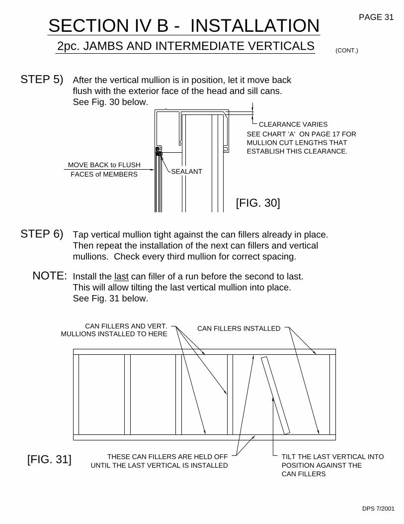
ESTABLISH THIS CLEARANCE.MULLION CUT LENGTHS THATSEE CHART ’A’ ON PAGE 17 FOR
CLEARANCE VARIES
2pc. JAMBS AND INTERMEDIATE VERTICALS
mullions. Check every third mullion for correct spacing.
Tap vertical mullion tight against the can fillers already in place.Then repeat the installation of the next can fillers and vertical
SECTION IV B - INSTALLATION
After the vertical mullion is in position, let it move back
CAN FILLERSPOSITION AGAINST THETILT THE LAST VERTICAL INTO
This will allow tilting the last vertical mullion into place.Install the last can filler of a run before the second to last.
UNTIL THE LAST VERTICAL IS INSTALLEDTHESE CAN FILLERS ARE HELD OFF[FIG. 31]
FACES of MEMBERSMOVE BACK to FLUSH
MULLIONS INSTALLED TO HERECAN FILLERS AND VERT.
See Fig. 31 below.
NOTE:
STEP 6)
CAN FILLERS INSTALLED
SEALANT
[FIG. 30]
flush with the exterior face of the head and sill cans.See Fig. 30 below.
STEP 5)
DPS 7/2001
PAGE 31
(CONT.)

DPS 7/2001
See Fig. 32 below.
cans similar to the captured mullion. Then it is tapped against the canThe vertical butt glazed mullion is set into the rear portion of the HEAD/SILL
fillers as before. Proceed to the next vertical.
SECTION IV C - INSTALLATION
SILL CAN
STEP 1)
GLAZED MULLIONVERTICAL BUTT
[FIG. 32]
CAN FILLERINSTALLED
BUTT GLAZED VERTICALS
PAGE 32

IN HEAD/SILL CAN
THIS HALF OFMULLION IS SET
MULLION IS SETIN HEAD/SILL CAN
FACE TAPE
FIRST.
[FIG. 34]
THIS HALF OF
FIRST.
THIS HALF OF
FIRST.
MULLION IS SETIN HEAD/SILL CAN
FACE TAPE
DPS 7/2001
SECTION IV C - INSTALLATION
#7256
#7256 MULL HALF MUST BEINSTALLED BEFORE #7255MULL HALF.
NOTE:
STEP 2)
pertaining to available degree of corner combinations.
(2) 9563 FOR90 CORNER(903 & 904)
Below are butt glazed corner mullion halves for each system
APPLY DOUBLE
(2) 7260 FOR
(901 & 902)135 CORNER
(901 & 902)CORNERfor 90#7255
[FIG. 33]
(903 & 904)135 CORNER(2) 9562 F0R
APPLY DOUBLE
SILL CAN
#7255
BUTT GLAZED VERTICALS
Refer to the figures below to determine the related parts.
The butt glazed corners are (2) piece and require the firsthalf of the corner to be installed and then the other half.
PAGE 33
(cont.)

901/902 - 7260/7260 135 DEG. INSIDE - K491901/902 - 7260/7260 135 DEG. OUTSIDE - K490901/902 - 7255/7256 90 DEG. INSIDE OR OUTSIDE - K493
BUTT GLAZED VERTICALS
90 CORNER SHOWN BELOW IN FIG. 35, OTHERS SIMILAR.
FLAT HEAD SCREW SUPPLIED IN THE SHEAR BLOCK PACKAGE.ATTACH THE HORIZONTAL TO THE SHEAR BLOCKS WITH THE
TYPICAL SHEAR BLOCK ATTACHMENT FOR S.S.G. CORNERS.
SHEAR BLOCKPACKAGE
[FIG. 35]
K493
8583 HORIZ. SHOWNOTHER HORIZ. TYP.
STEP 3)
SECTION IV C - INSTALLATION
MULLION
DPS 7/2001
3/4" TO TOP
OTHERS SIMILARMULLION SHOWNS.S.G. CORNER7255/7256
OF HORIZONTAL
(cont.)
EDGE OF
PAGE 34
STK4 1.132"
2.117
STV2

[FIG. 37]
903/904
RO
TA
TE
K141
K176
901/902
[FIG. 36]
Refer to pages 11 and 12 for drilling templates.
Shear block locations may be drilled before verticals are installed
INTERMEDIATE HORIZONTAL
Install shear block to vertical using (3) #10-24 x 1 3/4" PL-PH-SMS.
horizontal is screw attached to the shear block with901/902 shear block and horizontal do not snap fit. TheRotate the horizontal over the shear block until it snaps in place.
"Butter" ends of horizontals with a butyl type sealant (nonhardening).
(2) #12-24 x 1/2" PH-FH-TYPE "F" SCREWS. (#S110)See Fig. 37 below.
THE SHEAR BLOCK UNTIL ITROTATE THE HORIZONTAL OVER
SNAPS INTO PLACE.
STEP 4)
9564 - 9049586 - 903
BUTYL TYPE SEALANTACROSS THE ENDS
TYPICAL VERTICAL MEMBER2 pc. JAMB SHOWN
SECTION IV D - INSTALLATION
or after installation.
STEP 2)
STEP 3)
STEP 1)
904 SHOWN903 SIMILAR
901-902 Horizontal Notching.Refer to Page 22 for
S110
9469 - 9018583 - 902
HORIZONTAL
(Includes (3) MRF8 SCREWS
K-141 for 903/904K-176 for 901/902
PAGE 35
& (1) S110 SCREW)
JDA 10/2001

Systems 901 and 903 use K-143.Systems 902 and 904 use K-142.
HORIZONTAL BRIDGE
vertical. Correct sealing is important in this step.
The horizontal bridge is intended to prevent any water in the glazingpocket from running down the butt glazed vertical intermediate at the
STEP 6)
BUTYL TYPE SEALANT.
SEAL AROUND BRIDGEWITH NONHARDENING
GASKET RACERUN SEALANT INTO
[FIG. 39]
JDA 2/14/02
BUTT GLAZED
HORIZONTALMULLION
INTERMEDIATE HORIZONTAL
BUTYL TYPE SEALANT
SECTION IV D - INSTALLATION
CAPTURED VERTICAL
CAPTURED JAMB SHOWN,
INTERMEDIATE IS SIMILAR.
902 SIMILAR904 SYSTEM SHOWN
STEP 5)
HWD1
"V" NOTCH
NOTE:
HORIZONTAL
WATER DEFLECTOR
NOTCH LEG AT
TOWARD THE EXTERIOR.POSITION WITH NOTCH
[FIG. 38]
PAGE 36
(CONT.)
Quick Set
Water deflectors are used at both ends of horizontal intermediates and
are intended to divert any water in the glazing pocket from reaching and
eventually sitting on top of the insulated glass unit below. Water
deflectors are not used with V.B.G. mullions or with 901 and 903.
See Fig. 38 below.

PAGE 37
SECTION V A - GLAZING PROCEDURES
STEP 1)
the ends.
INTERSECTIONS.
FOR BUTT GLAZED VERTICAL
from the exterior; install the interior gasket as follows.the front of the butt glazed vertical. The glass will be installed
the middle, then to quarter points and work the "WAVES" towardStart by pushing the gasket in place at the ends. Move to
The jamb gasket will run between. The gasket will run acrossGlazing gasket (W164) will be continuous in the head / sill cans.
TO ITS ORIGINAL FORM, CREATING GAPS AT THE GASKETDO NOT STRETCH THE GASKET OR IT WILL RETURN
GASKET RUNS TO JAMB
[FIG. 40]
SILL
VERTICALBUTT GLAZED
GASKET RUNS TO JAMB
9485
HN33 - 902HN34 - 904
W164
9484
CDB 9/2009
HEAD
VARIES8" - 12"
JAMB
RUN THRU.JAMB GASKET TO
SEALANT
9479
9485
W164
STEP 2)
HNA1 - 901HNA2 - 903
pockets. See Fig. 41 below.Install setting block assemblies at 1/4 points in the sill can glazing
GASKET LENGTH = D.L.O. + 2%
BEFORE THE GASKETS ARE INSTALLED, SEAL 1"VERTICALLY AND HORIZONTALLY IN THE GASKETRACES WITH SILICONE TYPE SEALANT AT ALLCORNERS. AFTER INSTALLATION SEAL THE ENDSOF ALL GASKETS. SEALING RACES & GASKET END ISREQUIRED AT THE INTERIOR OF THE SYSTEM.EXTERIOR SEALANT AT RACE AND GASKETS AREOPTIONAL.
FU08 @ 1G66902 I-BAR CAN
[FIG. 41]
See Fig. 40 below.

[FIG. 43]
Refer to page 17 for the cut lengths for the butt glazed mullions.
Install the glazing gasket to the interior gasket track as shown below.
on the required center lines. Refer to page 31 to set the mullions.Cut the can fillers to the correct length to position the vertical mullions
Fill the cavity in the vertical mullion behind the glazing gasket withsilicone sealant, 3/8" above and below the gasket. This should bedone at the head and sill can before the glass units are installed.See Fig. 43 below.
STEP 4)
[FIG. 42]
BUTT GLAZEDMULLION
FILLER
GASKET RUNS THRUAT VERTICALS
CAN
STEP 3)
DPS 7/2001
THE GLASS UNITS
THE GLAZING GASKET AT HEAD & SILL CANSBEFORE INSTALLING
FILL THIS CAVITY BEHIND
FILLER
JAMB
CAN
JAM
BG
LAS
S S
TO
P
(CONT.)
PAGE 38
FOR BUTT GLAZED VERTICAL
SECTION V A - GLAZING PROCEDURES
CENTER LINE
OF MULLION
CENTER LINE
OF MULLION
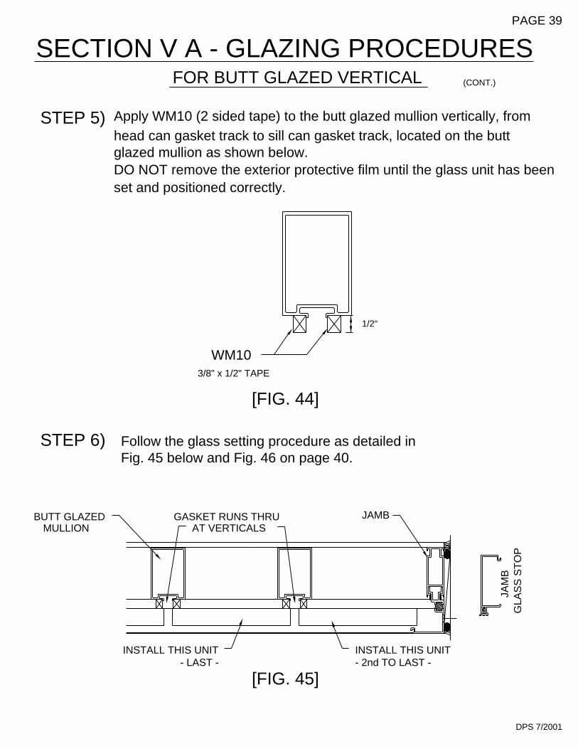
Fig. 45 below and Fig. 46 on page 40.Follow the glass setting procedure as detailed in
- LAST -INSTALL THIS UNIT
[FIG. 45]
GASKET RUNS THRUMULLION
BUTT GLAZED
STEP 6)
AT VERTICALS
[FIG. 44]
3/8" x 1/2" TAPE
WM10
DPS 7/2001
INSTALL THIS UNIT- 2nd TO LAST -
GLA
SS
ST
OP
JAM
BJAMB
1/2"
head can gasket track to sill can gasket track, located on the buttApply WM10 (2 sided tape) to the butt glazed mullion vertically, from
DO NOT remove the exterior protective film until the glass unit has beenglazed mullion as shown below.
set and positioned correctly.
STEP 5)
PAGE 39
SECTION V A - GLAZING PROCEDURES FOR BUTT GLAZED VERTICAL (CONT.)

SECTION V A - GLAZING PROCEDURES FORBUTT GLAZED VERTICAL
STEP 7) Lift the glass into the head can glazing pocket. Then set it down on the setting blocks in the sill can glazing pocket, and slide the glass horizontally into proper position.
NOTE: If there are no vertical intermediates being used, proceed to nstall the exterior glazing gasket as described at Step 1 on page 37.
HEAD
1/2"G.B.
9485
9484
W102
GLA
SS U
NIT
1/2"G.B.
W102
9485
9484HN33SILL
[FIG. 46]
DPS 6/2003QUICK SET
PAGE 40
(CONT.)

GLA
SS
ST
OP
Vertical glass size formula is DLO + 1". Horizontal glass size
DLO + 1 1/4" between butt glazed mullions and captured jambs.formula is DLO + 1 1/2" between butt glazed mullions, and
glass units into contact with the now exposed adhesive.Remove the exterior protective film on the glazing tape and press the
JAM
B
[FIG. 47]
GLASS UNIT
BUTT GLAZED
GLASS UNIT
GAP
[FIG. 48]GAP
MULLIONS
GLASS UNIT
GLASSBITE
1/2"
3/4"3/4"
BITEGLASS
BITEGLASS
3/4"
1/2"
BITEGLASS
3/4"
B)
GASKET RUNS THRUAT VERTICALS
1/2"
DPS 12/2002
BITEGLASS
1/2"
JAMB
At the jamb, install the glazing stop and the vertical glazing gasket.
WHEN THE GLASS UNITS ARE POSITIONED CORRECTLY-STEP 8)
2 PC. JAMB
A)
PAGE 41
(CONT.)FOR BUTT GLAZED VERTICAL
SECTION V A - GLAZING PROCEDURES
Quick Set

ARE BACK TO BACK.THEM TOGETHER UNTIL THE CLIPS
HOOK THE TEMPORARY GLAZING CLIPSINTO THE MULLION CAVITY AND SLIDE
Locate the glazing clips with a spacing of 24" on center maximum.
FOR SAFETY, THE USE OF GLAZING CLIPS IS RECOMMENDED.
Install the exterior glazing gasket in the same manner as
GLASS UNIT
STEP 10)described in Step 1, page 37.
GLASS UNIT
[FIG. 50]
24"
MA
XIM
UM
BUTT GLAZEDMULLION
[FIG. 49]HV11901/903
WM10
STEP 9)See Fig. 49 and Fig. 50 below.
DPS 7/2001
HV10902/904
PAGE 42
SECTION V A - GLAZING PROCEDURES FOR BUTT GLAZED VERTICAL (CONT.)

902/904
Apply the structural silicone to the interior side tying themullion, spacer tape, and glass unit together.
HV10
[FIG. 52]
SILICONESTRUCTURAL
901/903HV11
STRUCTURALSILICONE
STEP 11)
DPS 7/2001
STRUCTURALSILICONE
WM10
SILICONESTRUCTURAL
[FIG. 51]
WM10
PAGE 43
SECTION V A - GLAZING PROCEDURES FOR BUTT GLAZED VERTICAL (CONT.)

DPS 7/2001
THE SUCCESS OF STRUCTURAL SILICONE GLAZED PROJECTS HASBEEN THE RESULT OF COMPATIBILITY TESTS PERFORMED ONACTUAL MATERIALS SUPPLIED TO THE PROJECT. THE INSTALLERMUST MAKE SURE THAT SUCCESSFUL COMPATIBILITY TESTS AREPERFORMED IN ACCORDANCE WITH THE SILICONE MANUFACTURER’SRECOMMENDATIONS AND PROCEDURES.
After the interior sealant has cured, typically an overnight setup isrequired. Then remove the temporary glazing clips and proceed with filling the void between the glass units at the exterior with backer
professional appearance.
rod and structural silicone sealant for a weather tight seal.Remove excess silicone from the glass surface for a neat and
NOTE:
[FIG. 53]
See Fig. 53 below.
STEP 12)
OF WEATHER SEAL.
SEE THE SILICONE MANUFACTURER’SINSTRUCTIONS FOR APPLICATION
PAGE 44
SECTION V A - GLAZING PROCEDURES FOR BUTT GLAZED VERTICAL (CONT.)

3
3a
set on the setting block.(2) Tip the glass to vertical.(3) Install the face cover.
(1) Tip the glass back to
GLASS BITE1/2"
SILL
1
3
SNAP ON HORIZONTALFACE AFTER ALL LITES
GLASS ABOVE HORIZONTALMUST BE OUTSIDE GLAZED.
ARE SET.
NOTE:
2
2
1
GLASS BITE1/2"
HEAD
STEP 1)
(3a) Set the glass on the
setting blocks.
[FIG. 54]DPS 12/2002
(3) Set the glass on the setting blocks.
(1a) Hold the glass vertical.
glass plane.
(2a) Rotate the glass to the
1a
2a
as described for the top lite,The glass unit may also be set
-OPTIONAL AT LOWER LITE-
except from the inside.
HORIZONTAL
(2) Raise the glass to clear theglazing pocket.
(1) Tip the glass into the head
setting blocks.
PAGE 45
SECTION V B - GLAZING PROCEDURES FOR BUTT GLAZED VERTICAL AND INTERMEDIATE HORIZONTAL
Quick Set
WHEN A HORIZONTAL INTERMEDIATE IS BEING USED, GLASS SETTING OPTIONS INCLUDE INSIDE/OUTSIDE GLAZING OPPORTUNITIES. THE GLASS ABOVE THE HORIZONTAL WILL BE SET FROM THE OUTSIDE, AND THE GLASS BELOW MAY BE SET FROM THE OUTSIDE OR THE INSIDE. SEE FIG. 54 BELOW.

FOR CAPTURED VERTICAL MULLION
RUNS THRU
[FIG. 55] DPS 7/2001
FORMULA IS DLO + 7/8" HORIZONTALLY AND VERTICALLY.WHEN USING A CAPTURED VETICAL MULLION, THE GLASS SIZE
STOPS
opening increases. The same glass setting options included in
REMOVABLE VERTICAL
AND INTERMEDIATE HORIZONTAL
setting of the top lite becomes available also.Section V B will be available with this mullion, and the inside glass
become easier because the number of removable stops perWhen using a captured vertical mullion, glass setting tends to
HORIZONTAL STOP
STOPS
REMOVABLEVERTICAL
See Fig. 55 below.
NOTE:
STOPS
REMOVABLE
VERTICAL
2 pc. JAMB
SECTION V C - GLAZING PROCEDURES PAGE 46

and also in Fig. 57 through Fig. 60 on page 48.Anchor the door frame and threshold as indicated below in Fig. 56 below
Set the assembled door frame in the opening, plumb and level.
(9950)THRESHOLD
OF SEALANTCONTINUOUS BEAD
See the parts description pages in SECTION II for the appropriatedoor jamb and transom bar for the system being used.
jamb, continuing under the threshold to the opposite jamb andconnected from the side lite sill can/condition through the doorThe concept is to have a continuous bead of sealant at the interior
sealant into the bead of sealant to be applied under the threshold.to set the member into. Tie the side lite sealant or condition
Apply a bead of sealant around the interior portion of the jamb
SECTION VI A - DOOR FRAME INSTALLATION
Correctly locate the entrance frame in the opening.
NOTE: If an entrance frame is required, it must be installed first.
onto the opposite side lite sill can.
[FIG. 56]
floor and is cut longer
K-153/K-154 Threshold Clip & Screws@ Concealed Rod Panic
K-124/K-125 Threshold Clip & Screws
than any other vertical
@ Offset Pivots & Butt Hinges
member.
SIDE LITE SILL CAN
The door jamb runs to theNOTE:
STEP 4)
STEP 2)
STEP 3)
STEP 1)
DPS 7/2001
12" MAX.
THRESHOLD FASTENER12" FROM JAMB & 12" O.C.(3) PER SINGLE DOOR
PAGE 47

FOR MORE DETAILED STEPS, PART # Y015.SEE THE DOOR AND HARDWARE INSTALLATION INSTRUCTIONS
JDA 3/2002
screws, located 6" from
At condition, attach throughthe header with flat head
maximum spacing.the ends and 24" on center,
Attach through the threshold with flat head screws.
at the condition.
DOOR JAMB SET IN SEALANT
ANCHOR THROUGH THE JAMB
the back of the threshold and sides of theContinuous bead of sealant at
jambs, and tied into mullion sealant
12" from jambs and 12" on center max.
AT THE DOOR LOCATION.
[FIG. 60]
9154/9155
W138
[FIG. 59]
EXTERIOR INTERIOR
[FIG. 57]
W138
K273 RHK274 LH
9593
9914
CLIPTHRESHOLD
FRAMINGSIDE LITE
9154/9155
W138
9914
[FIG. 58]
W138
9593
K274 LHK273 RH
(CONT.)
SECTION VI A - DOOR FRAME INSTALLATION
PAGE 48
1/4" Dia. Weep
at 1/4 Points
5/8"
Quick Set

SECTION VI A - DOOR FRAME INSTALLATION
BAB 11/2001
CONT.
PAGE 49
[FIG. 61]
11/16"
1/4"
[FIG. 62]
TRANSOM/JAMB GLAZING ADAPTOR ANCHORING
Use the Transom/Jamb Glazing Adaptor (ext. #9295) with Jamb #9597, Glazing Stop
#9133 and 1/4" Glazing Adaptor #9261 at 901. At 902, use the Transom/Jamb Glazing
Adaptor #9295 with Jam #9592 and Glazing Stop #9133.
Anchor the Transom/Jamb Glazing Adaptor as shown in Fig. 61.
REMOVEABLE GLASS STOP CUT LENGTH AND FABRICATION
NOTCH THESE SURFACES
1/4" (AS SHOWN)
TYPICAL AT EACH END
Removeable Glass Stop (ext. #7861)
Cut length = Head Length - 1/16".
9295
STT6
16" MAX. O.C. 16" MAX. O.C. 16" MAX. O.C. 4"4"

SECTION VI A - DOOR FRAME INSTALLATION
Apply sealant to the ends of the header and vertical glazing adaptor as shown infasten into place with #STT6 screws, 4" from the ends and 12" on center maximum.Apply a thin bead of sealant vertically to set the screw applied glazing stop into. Then
Apply sealant to the ends of the header and install with the screws provided.Attach the header to the condition with 1/4" diameter fasteners minimum, 6" from
Temporarily locate the header / clip combination at the correct mounting position tolocate and drill the mounting holes for the clip into the jamb.
Slide the header clip onto the end of the header. Drill and fasten the clip to the header
TRANSOM HEADER AND APPLIED TRANSOM GLAZING
Fig. 63 above.
SET IN A BEAD OF SEALANT VERTICALLY
the jambs and 16" on center maximum.
with the screws provided in the clip package.
9295
SCREWS#STT6
SEALANT
SEALANT
BAB 11/2001
[FIG. 63]
CONT.
PAGE 50
9539 @ 902(901 SIMILIAR)
K267 CLIP @ 902K277 CLIP @ 901
9592 DOOR JAMB @ 902(901 SIMILIAR)
9484 HEAD CAN AT THE SIDE LITE TYP. @ 902(901 SIMILIAR)