Embed Size (px)
Citation preview
Quick SAS Cabling Guide
A Dell Technical White Paper
PowerVault™ MD3200 and MD3200i Storage Arrays

Quick SAS Cabling Guide
Page ii
THIS WHITE PAPER IS FOR INFORMATIONAL PURPOSES ONLY, AND MAY CONTAIN TYPOGRAPHICAL
ERRORS AND TECHNICAL INACCURACIES. THE CONTENT IS PROVIDED AS IS, WITHOUT EXPRESS OR
IMPLIED WARRANTIES OF ANY KIND.
© 2010 Dell Inc. All rights reserved. Reproduction of this material in any manner whatsoever without
the express written permission of Dell Inc. is strictly forbidden. For more information, contact Dell.
Dell, the DELL logo, and the DELL badge, PowerConnect, and PowerVault are trademarks of Dell Inc.
Other trademarks and trade names may be used in this document to refer to either the entities
claiming the marks and names or their products. Dell Inc. disclaims any proprietary interest in
trademarks and trade names other than its own.
July 2010

Quick SAS Cabling Guide
Page 1
Contents Components of Dell PowerVault™ MD32xx/MD32xxi System ........................................................ 2
Supported System Configurations ........................................................................................ 4
Fault-tolerant Asymmetric Cabling Scheme ........................................................................... 5
Simple Cascade Cabling Scheme ......................................................................................... 5
Diagrams ..................................................................................................................... 5
Tables
Table 1. Supported System Configurations ........................................................................... 4
Figures
Figure 1. Simple Cascade Cabling Scheme: Configuration C01 ....................................................... 6
Figure 2. Simple Cascade Cabling Scheme: Configurations C02, C03 ............................................... 7
Figure 3. Simple Cascade Cabling Scheme: Configurations C04, C05, C06 ......................................... 8
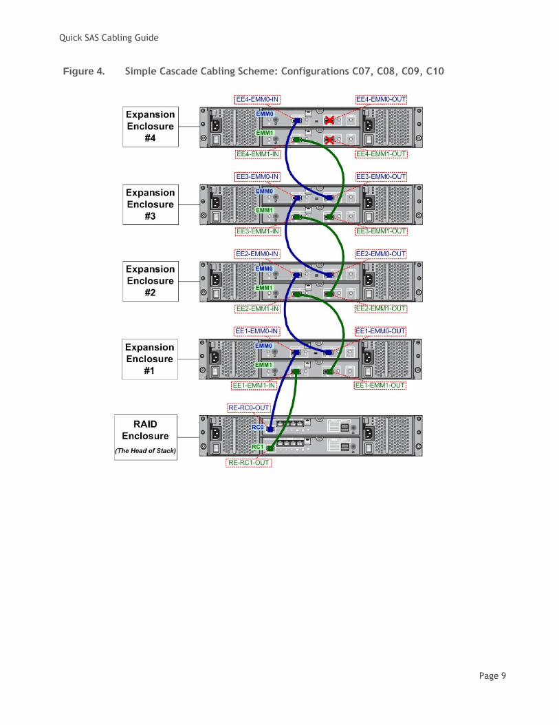
Figure 4. Simple Cascade Cabling Scheme: Configurations C07, C08, C09, C10 .................................. 9
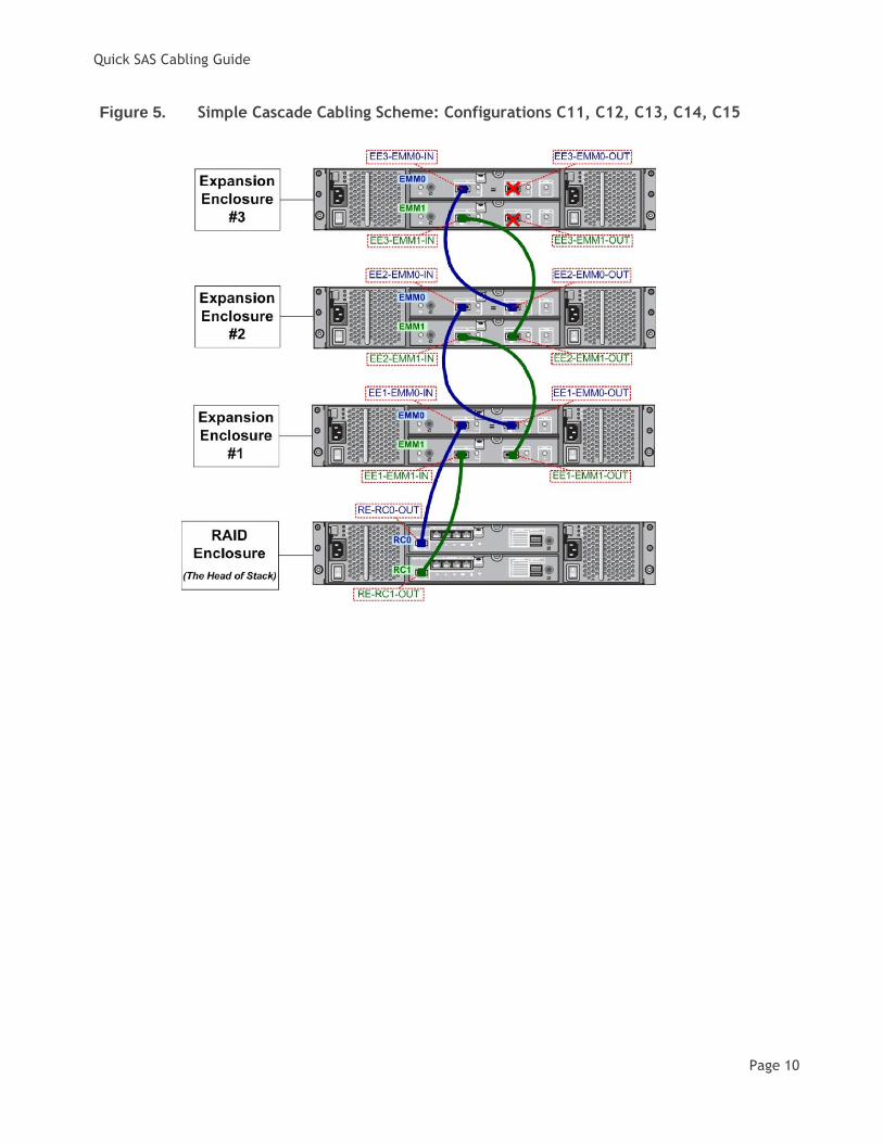
Figure 5. Simple Cascade Cabling Scheme: Configurations C11, C12, C13, C14, C15 .......................... 10
Figure 6. Simple Cascade Cabling Scheme: Configurations C16, C17, C18, C19 ................................ 11
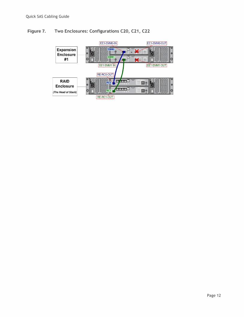
Figure 7. Two Enclosures: Configurations C20, C21, C22 ........................................................... 12
Figure 8. Single Enclosure: Configurations C23, C24 ................................................................. 13
Figure 9. Fault-tolerant Asymmetric Cabling Scheme: Configurations C01 ...................................... 14
Figure 10. Fault-tolerant Asymmetric Cabling Scheme: Configurations C02, C03................................ 15
Figure 11. Fault-tolerant Asymmetric Cabling Scheme: Configurations C04, C05, C06 ......................... 16
Figure 12. Fault-tolerant Asymmetric Cabling Scheme: Configurations C07, C08, C09, C10 ................... 17
Figure 13. Fault-tolerant Asymmetric Cabling Scheme: Configurations C11,C12,C13,C14,C15 ................ 18
Figure 14. Fault-tolerant Asymmetric Cabling Scheme: Configurations C16, C17, C18, C19 ................... 19
Figure 15. SAS Cable Labels ................................................................................................ 20

Quick SAS Cabling Guide
Page 2
Components of Dell PowerVault™ MD32xx/MD32xxi System
The following are the integral blocks of the Dell PowerVault™ MD32xx/MD32xxi storage array systems:
1. MD3200 is the SAS RAID array residing in the enclosure with 12 horizontally positioned 3.5" disk slots
2. MD3220 is the SAS RAID array residing in the enclosure with 24 vertically positioned 2.5" disk slots
3. MD3200i is the iSCSI RAID array residing in the enclosure with 12 horizontally positioned 3.5" disk slots
4. MD3220i is the iSCSI RAID array residing in the enclosure with 24 vertically positioned 2.5" disk slots
5. MD1200 is the RAID array expansion residing in the enclosure with 12 horizontally positioned 3.5"
disk slots
6. MD1220 is the RAID array expansion residing in the enclosure with 24 vertically positioned 2.5" disk
slots
MD3200 and MD3220 back view:
MD3200i and MD3220i back view:
MD1200 and MD1220 back view:
Front view of MD3200/MD3200i/MD1200 (top) and MD3220/MD3220i/MD1220 (bottom):
NOTE:
Only a single SAS or iSCSI RAID array must
be present in the system.
NOTE:
This guide makes an assumption that the
user has MD32xx/MD32xxi system operating
in the duplex mode (the recommended
mode of operation), i.e. when both RAID
controllers are present and are fully
operational.

Quick SAS Cabling Guide
Page 3
MD32xx SAS RAID array has SAS RAID controllers (RCs): MD32xxi iSCSI RAID array has iSCSI RAID controllers (RCs):
Array expansion enclosure has enclosure management modules (EMMs):

Quick SAS Cabling Guide
Page 4
Supported System Configurations
The MD32xx/MD32xxi storage array system may consist of the following twenty four order independent
combinations of the enclosures with 12 horizontally positioned 3.5" disk slots and the enclosures with 24
vertically positioned 2.5" disk slots.
Table 1. Supported System Configurations
Config.
ID
Total
Number of
Enclosures
Maximum
Number
of Disks
Number of
Enclosures
with 12
Disk Slots
Number of
Enclosures
with 24
Disk Slots
Simple Cascade
Scheme
Illustration
Fault-tolerant
Asymmetric
Cabling Scheme
Illustration
C01 8 96 8 0 (hyperlink) Figure 1 (hyperlink) Figure 9
C02 7 96 6 1 (hyperlink) Figure 2 (hyperlink) Figure 10
C03 7 84 7 0 (hyperlink) Figure 2 (hyperlink) Figure 10
C04 6 96 4 2 (hyperlink) Figure 3 (hyperlink) Figure 11
C05 6 84 5 1 (hyperlink) Figure 3 (hyperlink) Figure 11
C06 6 72 6 0 (hyperlink) Figure 3 (hyperlink) Figure 11
C07 5 96 2 3 (hyperlink) Figure 4 (hyperlink) Figure 12
C08 5 84 3 2 (hyperlink) Figure 4 (hyperlink) Figure 12
C09 5 72 4 1 (hyperlink) Figure 4 (hyperlink) Figure 12
C10 5 60 5 0 (hyperlink) Figure 4 (hyperlink) Figure 12
C11 4 96 0 4 (hyperlink) Figure 5 (hyperlink) Figure 13
C12 4 84 1 3 (hyperlink) Figure 5 (hyperlink) Figure 13
C13 4 72 2 2 (hyperlink) Figure 5 (hyperlink) Figure 13
C14 4 60 3 1 (hyperlink) Figure 5 (hyperlink) Figure 13
C15 4 48 4 0 (hyperlink) Figure 5 (hyperlink) Figure 13
C16 3 72 0 3 (hyperlink) Figure 6 (hyperlink) Figure 14
C17 3 60 1 2 (hyperlink) Figure 6 (hyperlink) Figure 14
C18 3 48 2 1 (hyperlink) Figure 6 (hyperlink) Figure 14
C19 3 36 3 0 (hyperlink) Figure 6 (hyperlink) Figure 14
C20 2 48 0 2 (hyperlink) Figure 7 (hyperlink) Figure 7
C21 2 36 1 1 (hyperlink) Figure 7 (hyperlink) Figure 7
C22 2 24 2 0 (hyperlink) Figure 7 (hyperlink) Figure 7
C23 1 24 0 1 (hyperlink) Figure 8 (hyperlink) Figure 8
C24 1 12 1 0 (hyperlink) Figure 8 (hyperlink) Figure 8

Quick SAS Cabling Guide
Page 5
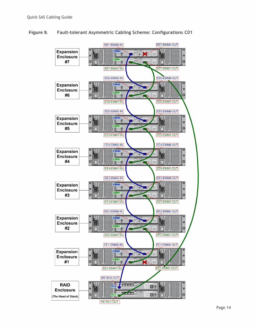
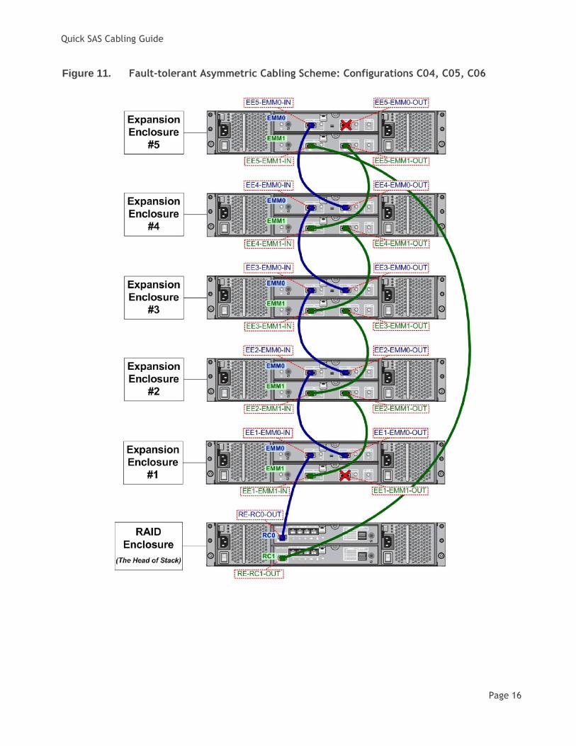
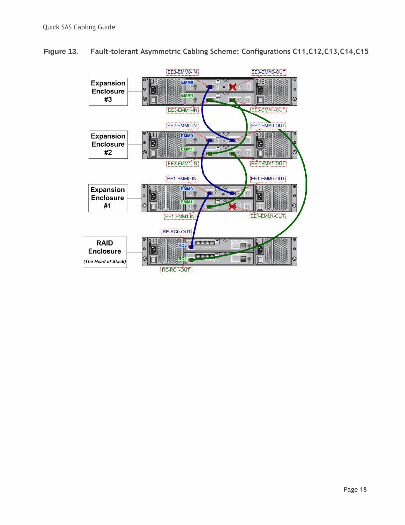
Fault-tolerant Asymmetric Cabling Scheme
Although more complex to set up, the fault-tolerant asymmetric cabling scheme is the recommend way of
connecting the expansion enclosures to the RAID array as it makes the enclosure loss protection possible. Enclosure loss protection is an attribute of a disk group. Enclosure loss protection guarantees accessibility
to the data on the virtual disks in a disk group if a total loss of communication occurs with a single
expansion enclosure. An example of total loss of communication might be loss of power to the expansion
enclosure or failure of both EMM modules. Naturally, the enclosure loss protection is not guaranteed if a
physical disk has already failed in the disk group. In this situation, losing access to an expansion enclosure
and consequently another physical disk in the disk group causes a double physical disk failure and loss of
data. Enclosure loss protection is achieved when you create a disk group where all of the physical disks that
comprise the disk group are located in different expansion enclosures. This distinction depends on the RAID
level. For the diagram illustrating how to cable the specific configuration you have please see (hyperlink) Table 1
Note: An incorrect SAS cabling will be detected by the array system. The MD32xx/MD32xxi Storage Manager
will warn you about the mis-wired enclosures by logging a major event in the event log. In addition, the
Recovery Guru will point you to the mis-wire condition and provide you some guidance on correcting the
problem. Please remember that a mis-wire condition will only be reported if incorrectly plugged SAS cables
result in a non-working configuration. In theory, it is possible to attach the expansion enclosures in a
technically correct manner, which will not be optimal but still be functional. The mis-wire events will not
be logged for a configuration of this type.
Simple Cascade Cabling Scheme
The simple cascade cabling scheme could be used when the enclosure loss protection is not required.
The advantage of using this scheme is the simplicity of the initial system set up.
For the diagram illustrating how to cable the specific configuration you have please see (hyperlink) Table 1
Diagrams
This section contains diagrams illustrating the MD32x/MD32xxi system configurations.
The last diagram (hyperlink) Figure 15 contained in this section is a special case: it contains picture of the
labels which you can print, cut out and attach to the both ends of every SAS cable used in your
configuration for an easy identification. If after initial wiring your array system has to be
transported/moved then the labeled SAS cables will simplify the task of re-assembling the system.

Quick SAS Cabling Guide
Page 6
Figure 1. Simple Cascade Cabling Scheme: Configuration C01

Quick SAS Cabling Guide
Page 7
Figure 2. Simple Cascade Cabling Scheme: Configurations C02, C03

Quick SAS Cabling Guide
Page 8
Figure 3. Simple Cascade Cabling Scheme: Configurations C04, C05, C06
Quick SAS Cabling Guide
Page 9
Figure 4. Simple Cascade Cabling Scheme: Configurations C07, C08, C09, C10
Quick SAS Cabling Guide
Page 10
Figure 5. Simple Cascade Cabling Scheme: Configurations C11, C12, C13, C14, C15

Quick SAS Cabling Guide
Page 11
Figure 6. Simple Cascade Cabling Scheme: Configurations C16, C17, C18, C19
Quick SAS Cabling Guide
Page 12
Figure 7. Two Enclosures: Configurations C20, C21, C22

Quick SAS Cabling Guide
Page 13
Figure 8. Single Enclosure: Configurations C23, C24
Quick SAS Cabling Guide
Page 14
Figure 9. Fault-tolerant Asymmetric Cabling Scheme: Configurations C01

Quick SAS Cabling Guide
Page 15
Figure 10. Fault-tolerant Asymmetric Cabling Scheme: Configurations C02, C03
Quick SAS Cabling Guide
Page 16
Figure 11. Fault-tolerant Asymmetric Cabling Scheme: Configurations C04, C05, C06

Quick SAS Cabling Guide
Page 17
Figure 12. Fault-tolerant Asymmetric Cabling Scheme: Configurations C07, C08, C09, C10
Quick SAS Cabling Guide
Page 18
Figure 13. Fault-tolerant Asymmetric Cabling Scheme: Configurations C11,C12,C13,C14,C15

Quick SAS Cabling Guide
Page 19
Figure 14. Fault-tolerant Asymmetric Cabling Scheme: Configurations C16, C17, C18, C19

Quick SAS Cabling Guide
Page 20
Figure 15. SAS Cable Labels
Labels for SAS Cables
(Cut out the labels and attach them to the ends of the SAS cables
RE-RC0-OUT RE-RC1-OUT
EE1-EMM0-IN EE1-EMM0-OUT EE1-EMM1-IN EE1-EMM1-OUT
EE1-EMM0-IN EE1-EMM0-OUT EE1-EMM1-IN EE1-EMM1-OUT
EE2-EMM0-IN EE2-EMM0-OUT EE2-EMM1-IN EE2-EMM1-OUT
EE2-EMM0-IN EE2-EMM0-OUT EE2-EMM1-IN EE2-EMM1-OUT
EE3-EMM0-IN EE3-EMM0-OUT EE3-EMM1-IN EE3-EMM1-OUT
EE3-EMM0-IN EE3-EMM0-OUT EE3-EMM1-IN EE3-EMM1-OUT
EE4-EMM0-IN EE4-EMM0-OUT EE4-EMM1-IN EE5-EMM1-OUT
EE4-EMM0-IN EE4-EMM0-OUT EE4-EMM1-IN EE5-EMM1-OUT
EE5-EMM0-IN EE5-EMM0-OUT EE5-EMM1-IN EE5-EMM1-OUT
EE5-EMM0-IN EE5-EMM0-OUT EE5-EMM1-IN EE5-EMM1-OUT
EE6-EMM0-IN EE6-EMM0-OUT EE6-EMM1-IN EE6-EMM1-OUT
EE6-EMM0-IN EE6-EMM0-OUT EE6-EMM1-IN EE6-EMM1-OUT
EE7-EMM0-IN EE7-EMM0-OUT EE7-EMM1-IN EE7-EMM1-OUT
EE7-EMM0-IN EE7-EMM0-OUT EE7-EMM1-IN EE7-EMM1-OUT