Embed Size (px)
Citation preview
gige Ethernet test gige Ethernet testing gige Ethernet installation gige Ethernet maintenance gige Ethernet commissioning, gige Ethernet troubleshooting,
Tren
dCom
mun
icat
ions
Gigabit Ethernet tester, Gigabit Ethernet testing, Gigabit Ethernet installation, Gigabit Ethernet maintenance, Gigabit Ethernet commissioning, Gigabit Ethernet troubleshooting, Gigabit Ethernet protocols, 1000BASE-T tester, 1000BASE-LX test, 1000BASE-SX test, 1000BASE-T testing, 1000BASE-LX testing, 1000BASE-SX testing,
Gigabit Ethernet protocols, 1000BASE-T tester, 1000BASE-LX test, 1000BASE-SX test, 1000BASE-T testing 1000BASE-LX testing 1000BASE-SX testing
MDI
OSI model
1
Data Link
Network
Transport
Session
Presentation
Application
Physical
2
3
4
5
6
7
LLC (802.2)
MAC (803.3)
PHY (802.3)
Upper
802.3 model
Reconciliation
PCS
PMA
Autonegotiation
MII
Upper layers
Media
Media
inde
pend
ent
Med
ia de
pend
ent
layers
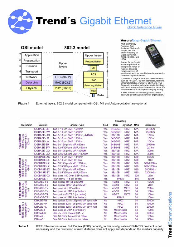
Figure 1 Ethernet layers, 802.3 model compared with OSI. MII and Autonegotiation are optional.
EncodingStandard Version Media Type FDX Data Symbol MFS Distance
10G
Ethe
rnet
IEEE
802
.3ae
(cla
use
48-5
3)XG
MII
10GBASE-ER Two 8-10 µm SMF, 1550nm Yes 64B/66B NRZ N/A 2/40Km10GBASE-EW Two 8-10 µm SMF, 1550nm Yes 64B/66B NRZ N/A 2/40Km10GBASE-LX4 Two 8-10 µm SMF, 1310nm, 4xDWM Yes 8B/10B NRZ N/A 10Km10GBASE-LR Two 8-10 µm SMF, 1310nm Yes 64B/66B NRZ N/A 10Km10GBASE-LW Two 8-10 µm SMF, 1310nm Yes 64B/66B NRZ N/A 10Km10GBASE-SR Two 50/125 µm MMF, 850nm Yes 64B/66B NRZ N/A 2/550m10GBASE-SW Two 62.5/125 µm MMF, 850nm Yes 64B/66B NRZ N/A 2/33m10GBASE-LX4 Two 50/125 µm MMF, 4xDWM Yes 8B/10B NRZ N/A 300m10GBASE-LX4 Two 62.5/125 µm MMF, 4xDWM Yes 8B/10B NRZ N/A 300m
Gig
abit
Ethe
rnet
IEEE
802
.3z/
ab(c
laus
es 3
4-42
)G
MII
1000BASE-ZX Two 8-10 µm SMF, 1310nm Yes 8B/10B NRZ 520 80Km1000BASE-LX Two 8-10 µm SMF,1310nm Yes 8B/10B NRZ 520 5Km1000BASE-LX Two 50/125 µm MMF, 1310nm Yes 8B/10B NRZ 520 550/2000m1000BASE-LX Two 62.5/125 µm MMF, 1310nm Yes 8B/10B NRZ 520 550/1000m1000BASE-SX Two 50/125 µm MMF, 850nm Yes 8B/10B NRZ 520 500/750m1000BASE-SX Two 62.5/125 µm MMF, 850nm Yes 8B/10B NRZ 520 220/400m1000BASE-CX Two pairs 150 Ohm STP (twinax) Yes 8B/10B NRZ 520 25m1000BASE-T Four pair UTP 5 (or better) Yes PAM5 416 100m
Fast
Eth
erne
tIE
EE 8
02.3
u(c
laus
es 2
1-29
)M
II
100BASE-Fx Two optical 50/125 µm SMF Yes 4B/5B NRZ 64 40Km100BASE-Fx Two optical 62.5/125 µm MMF Yes 4B/5B NRZ 64 2Km100BASE-Tx Two pairs of STP cables Yes 4B/5B MLT3 64 200m100BASE-Tx Two pairs of UTP 5 (or better) Yes 4B/5B MLT3 64 100m100BASE-T4 Four pairs of UTP 3 (or better) No 8B/6T MLT3 64 100m100BASE-T2 Two pairs of UTP 3 (or better) Yes PAM5 64 100m
Ethe
rnet
IEEE
802
.3a-
t(c
laus
es1-
20)
AUI
10BASE-FB Two optical 62.5 /125µm MMF sync hub No NRZI 64 2000m10BASE-FP Two optical 62.5/125 µm MMF pass hub No NRZI 64 1000m10BASE-FL Two optical 62.5/125 µm MMF asyn hub Yes NRZI 64 2000m10BASE-T Two pairs of UTP 3 (or better) Yes Manchester 64 100m10Broad36 One 75 Ohm coaxial (CATV) No Manchester 64 3600m10Base2 One 50 Ohm thin coaxial cable No Manchester 64 185m10Base5 One 50 Ohm thick coaxial cable No Manchester 64 500m
Table 1 IEEE Ethernet versions. Full Duplex (FDX) capacity, in this configuration CSMA/CD protocol is not necessary and the restriction of max. distance does not apply and depends on the media’s capacity.
Trend´s Gigabit EthernetQuick Reference Guide
AuroraTango Gigabit EthernetMulti-technology Personal Test Assistant Platform for simple, fast and effective testing of Gigabit Ethernet, ADSL, SHDSL, and ISDN.Aurora Tango Gigabit Ethernet provides an exceptional range of features ensuring reliable delivery of end-to-end services over Metropolitan networks based on Gigabit Ethernet.It provides a range of tests and measurements such as RFC2544, top ten addresses, real-time Ethernet statistics, multilayer BERT, etc. Two Gigaport transceivers allow terminate, loopback and monitor connections to networks, plus a 10/100/1000BASE-T cable port for legacy testing. A PDA provides an intuitive graphical menu structure for testing and workflow organization.
Gigabit Ethernet test, Gigabit Ethernet testing, Gigabit Ethernet installation, Gigabit Ethernet maintenance, Gigabit Ethernet commissioning, Gigabit Ethernet troubleshooting, Gigabit Ethernet protocols, Gigabit Ethernet Alarms, Gigabit Ethernet test, Gigabit Ethernet test, Gigabit Ethernet test, Gigabit Ethernet tester
Tren
dCom
mun
icat
ions
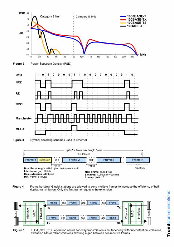
Figure 2 Power Spectrum Density (PSD)
20
1000BASE-T100BASE-TX100BASE-T210BASE-T
40 60 80 100 120 140 160 180 200 220 240 0 -50
-40
-30
-20
-10
-0
10
20
Category 3 limit Category 5 limit
MHz
dB
PSD
Figure 3 Symbol encoding schemes used in Ethernet
0
MLT-3
NRZ
0 1 0 0 01 1 1 0 0 0 00 0 0 0 1 0Data
RZ
NRZI
Manchester
Figure 4 Frame bursting. Gigabit stations are allowed to send multiple frames to increase the efficiency of half-duplex transmission. Only the first frame requests the extension.
gap
8192 bytes
Frame 1 extension
>96 bit
Frame 2 gap
>96 bit
Frame NFrame 2Frame 1
>96 bitValid frameMax. Burst length: 8192 bytes, last frame is valid
Inter-frame gap: 96 bitsMax. extension: 448 bytesMin. frame: 64 bytes
Max. Frame: 1518 bytesSlot time: 4.096us or 4096 bitsAttempt limit: 16
up to 5.4 times max. length frameup to 5.4 times max. length frame
Phys
ical
MAC
Inte
rface
Rx
Tx
Figure 5 Full duplex (FDX) operation allows two-way transmission simultaneously without contention, collisions, extension bits or retransmissions allowing a gap between consecutive frames.
Phys
ical
MAC
Inte
rface
Rx
Tx
buffe
r
Frame gap Frame gap Frame gap Frame
Frame gap Frame gap Frame gap Frame
buffe
r
Gigabit Ethernet test, Gigabit Ethernet testing, Gigabit Ethernet installation, Gigabit Ethernet maintenance, Gigabit Ethernet commissioning, Gigabit Ethernet troubleshooting, Gigabit Ethernet protocols, Gigabit Ethernet Alarms, Gigabit Ethernet test, Gigabit Ethernet test, Gigabit Ethernet test, Gigabit Ethernet tester
Tren
dCom
mun
icat
ions
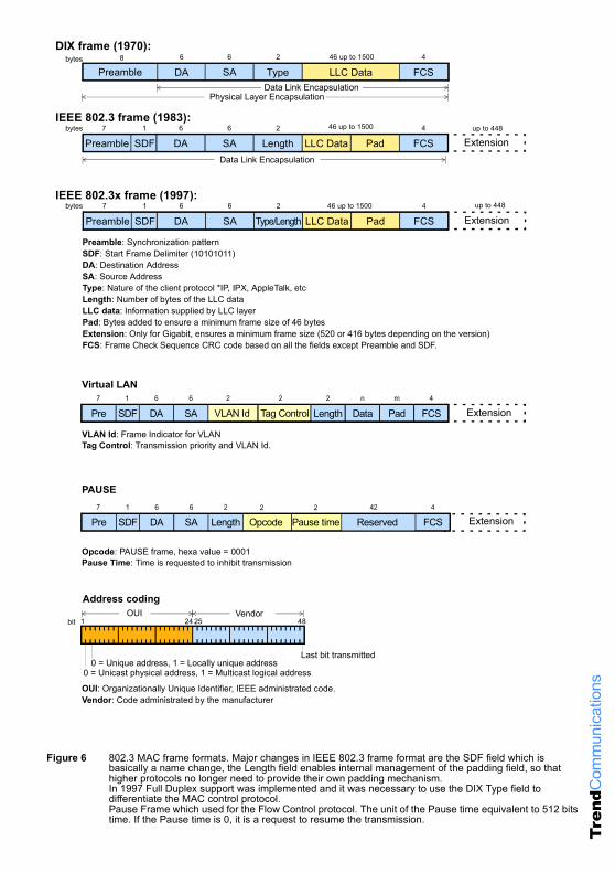
Figure 6 802.3 MAC frame formats. Major changes in IEEE 802.3 frame format are the SDF field which is basically a name change, the Length field enables internal management of the padding field, so that higher protocols no longer need to provide their own padding mechanism.In 1997 Full Duplex support was implemented and it was necessary to use the DIX Type field to differentiate the MAC control protocol.Pause Frame which used for the Flow Control protocol. The unit of the Pause time equivalent to 512 bits time. If the Pause time is 0, it is a request to resume the transmission.
Preamble: Synchronization patternSDF: Start Frame Delimiter (10101011)DA: Destination AddressSA: Source Address
Length: Number of bytes of the LLC dataLLC data: Information supplied by LLC layerPad: Bytes added to ensure a minimum frame size of 46 bytesExtension: Only for Gigabit, ensures a minimum frame size (520 or 416 bytes depending on the version)FCS: Frame Check Sequence CRC code based on all the fields except Preamble and SDF.
7
Preamble1
SDF6
DA6
SA2
Length LLC Data Pad4
FCS Extension
8
Preamble6
DA6
SA2
Type LLC Data4
FCS46 up to 1500
IEEE 802.3 frame (1983):
Type: Nature of the client protocol *IP, IPX, AppleTalk, etc
7
Preamble1
SDF6
DA6
SA2
Type/Length LLC Data Pad4
FCS Extension
IEEE 802.3x frame (1997):
Data Link Encapsulation
Data Link EncapsulationPhysical Layer Encapsulation
46 up to 1500
46 up to 1500
DIX frame (1970):
up to 448
up to 448
bytes
bytes
bytes
VLAN Id Tag Control7
Pre1
SDF6
DA6
SA2
Lengthn
Datam
Pad4
FCS
VLAN Id: Frame Indicator for VLANTag Control: Transmission priority and VLAN Id.
2 2
Virtual LAN
Extension
Opcode7
Pre1
SDF6
DA6
SA2
Length Reserved42 4
FCS
Opcode: PAUSE frame, hexa value = 0001 Pause Time: Time is requested to inhibit transmission
2
Pause time2
Extension
PAUSE
1
0 = Unicast physical address, 1 = Multicast logical address
Vendor
0 = Unique address, 1 = Locally unique addressLast bit transmitted
24 4825OUI
OUI: Organizationally Unique Identifier, IEEE administrated code.Vendor: Code administrated by the manufacturer
Address coding
bit
Gigabit Ethernet test, Gigabit Ethernet testing, Gigabit Ethernet installation, Gigabit Ethernet maintenance, Gigabit Ethernet commissioning, Gigabit Ethernet troubleshooting, Gigabit Ethernet protocols, Gigabit Ethernet Alarms, Gigabit Ethernet test, Gigabit Ethernet test, Gigabit Ethernet test, Gigabit Ethernet tester
Tren
dCom
mun
icat
ions
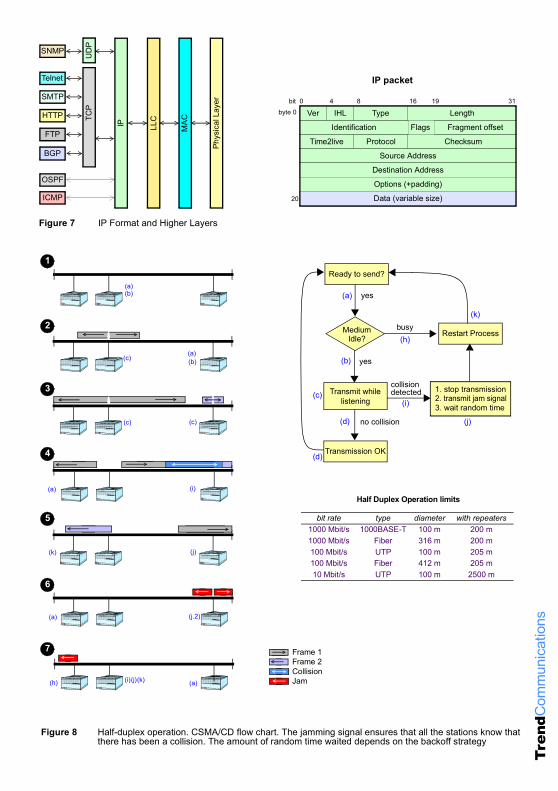
Figure 7 IP Format and Higher Layers
Ver Type LengthIHL
Identification Fragment offset
Time2live Protocol Checksum
Source Address
Destination Address
Options (+padding)
Data (variable size)
bit 0 314 8 1916
20
byte 0
FlagsIP
TCP
BGP
FTP
HTTP
SMTP
SNMP
TelnetU
DP
ICMP
OSPF
IP packet
LLC
MAC
Phys
ical
Lay
er
Figure 8 Half-duplex operation. CSMA/CD flow chart. The jamming signal ensures that all the stations know that there has been a collision. The amount of random time waited depends on the backoff strategy
Ready to send?
MediumIdle?
busy
Transmit whilelistening
collision 1. stop transmission2. transmit jam signal
yes
3. wait random time
Restart Process
detected
Transmission OK
yes
no collision
(a)
(b)
(h)
(d)
(i)
(b)(a)
(c)
(c)(c)
(c)
(i)(a)
(k)
(j)
(d)
(j)(k)
(a)(b)
(i)(j)(k)
(j.2)
(a)
(a)
(h)
1. stop transmission2. transmit jam signal3. wait random time
1
2
3
4
5
6
7
Half Duplex Operation limits
bit rate type diameter with repeaters1000 Mbit/s 1000BASE-T 100 m 200 m1000 Mbit/s Fiber 316 m 200 m100 Mbit/s UTP 100 m 205 m100 Mbit/s Fiber 412 m 205 m10 Mbit/s UTP 100 m 2500 m
Frame 1Frame 2CollisionJam
Gigabit Ethernet test, Gigabit Ethernet testing, Gigabit Ethernet installation, Gigabit Ethernet maintenance, Gigabit Ethernet commissioning, Gigabit Ethernet troubleshooting, Gigabit Ethernet protocols, Gigabit Ethernet Alarms, Gigabit Ethernet test, Gigabit Ethernet test, Gigabit Ethernet test, Gigabit Ethernet tester
Tren
dCom
mun
icat
ions
PCSPhy Coding Sublayer
PMAPhy Med Attachment
PMDPhy Med Dependent
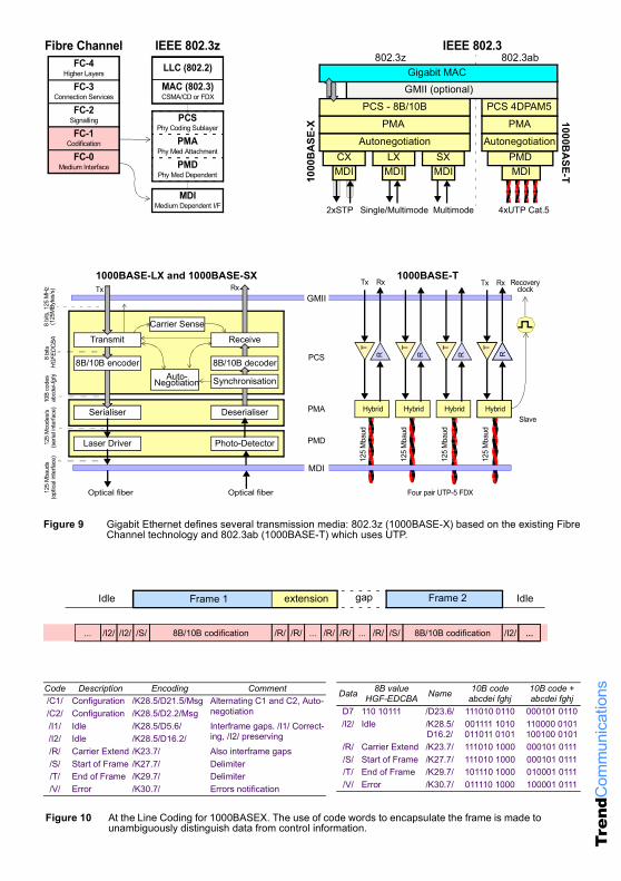
Figure 9 Gigabit Ethernet defines several transmission media: 802.3z (1000BASE-X) based on the existing Fibre Channel technology and 802.3ab (1000BASE-T) which uses UTP.
MDIPMD
MDICX
MDILX
MDISX
GMII (optional)PCS - 8B/10B
PMA Autonegotiation
Gigabit MAC
PCS 4DPAM5PMA
Autonegotiation
802.3z
2xSTP Single/Multimode Multimode 4xUTP Cat.5
1000BA
SE-T802.3ab
LLC (802.2)
MAC (802.3)CSMA/CD or FDX
MDIMedium Dependent I/F
FC-4Higher Layers
FC-3Connection Services
FC-0Medium Interface
FC-2Signalling
FC-1Codification
IEEE 802.3zFibre Channel IEEE 802.3
Receive
Serialiser
Optical fiber
8 bi
ts, 1
25 M
Hz
GMII
Auto-Negotiation
Carrier Sense(125
MBy
tes/
s)8
bits
10
B co
des
125
Mco
des/
s
8B/10B encoder 8B/10B decoder
Transmit
Laser Driver Photo-Detector(ser
ial in
terfa
ce)
Synchronisation
Deserialiser
125
Mba
uds
(opt
ical in
terfa
ce)
PMA
PMD
PCS
Optical fiber
abcd
ei-fg
hjH
GFE
DC
BA
T
Tx
Hybrid
R
Rx
125
Mba
ud
THybrid
R
125
Mba
ud
T
Hybrid
R
125
Mba
ud
T
H
R
125
Mba
udT
Hybrid
Recovery
Slave
Four pair UTP-5 FDXR
clock
MDI
1000BASE-T1000BASE-LX and 1000BASE-SXTx Rx Tx Rx
1000
BA
SE-X
extension gapFrame 1 Frame 2Idle Idle
/S/
extension
8B/10B codification/I2//I2/... /R/.../R//R/ /R/ ... /R/ /S/ 8B/10B codification .../I2/
Code Description Encoding Comment/C1/ Configuration /K28.5/D21.5/Msg Alternating C1 and C2, Auto-
negotiation/C2/ Configuration /K28.5/D2.2/Msg/I1/ Idle /K28.5/D5.6/ Interframe gaps. /I1/ Correct-
ing, /I2/ preserving/I2/ Idle /K28.5/D16.2//R/ Carrier Extend /K23.7/ Also interframe gaps/S/ Start of Frame /K27.7/ Delimiter/T/ End of Frame /K29.7/ Delimiter/V/ Error /K30.7/ Errors notification
Data 8B valueHGF-EDCBA Name 10B code
abcdei fghj10B code +abcdei fghj
D7 110 10111 /D23.6/ 111010 0110 000101 0110/I2/ Idle /K28.5/
D16.2/001111 1010011011 0101
110000 0101100100 0101
/R/ Carrier Extend /K23.7/ 111010 1000 000101 0111/S/ Start of Frame /K27.7/ 111010 1000 000101 0111/T/ End of Frame /K29.7/ 101110 1000 010001 0111/V/ Error /K30.7/ 011110 1000 100001 0111
...
Figure 10 At the Line Coding for 1000BASEX. The use of code words to encapsulate the frame is made to unambiguously distinguish data from control information.
Gigabit Ethernet test, Gigabit Ethernet testing, Gigabit Ethernet installation, Gigabit Ethernet maintenance, Gigabit Ethernet commissioning, Gigabit Ethernet troubleshooting, Gigabit Ethernet protocols, Gigabit Ethernet Alarms, Gigabit Ethernet test, Gigabit Ethernet test, Gigabit Ethernet test, Gigabit Ethernet tester
Tren
dCom
mun
icat
ions
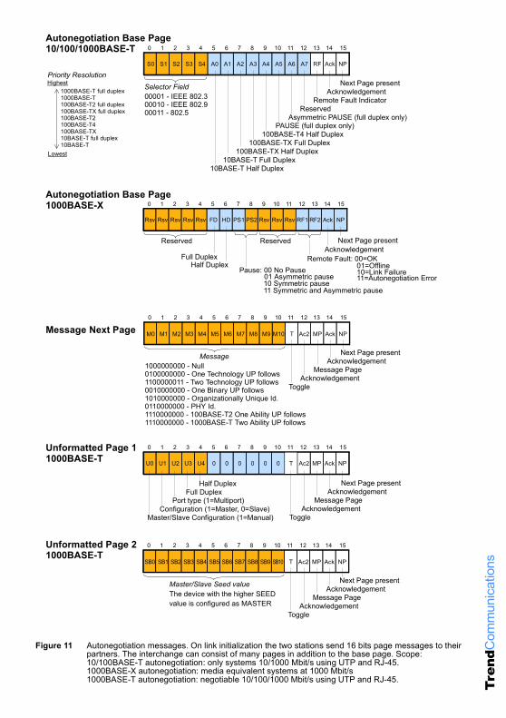
Figure 11 Autonegotiation messages. On link initialization the two stations send 16 bits page messages to their partners. The interchange can consist of many pages in addition to the base page. Scope:10/100BASE-T autonegotiation: only systems 10/1000 Mbit/s using UTP and RJ-45. 1000BASE-X autonegotiation: media equivalent systems at 1000 Mbit/s1000BASE-T autonegotiation: negotiable 10/100/1000 Mbit/s using UTP and RJ-45.
Acknowledgement
S0 S1 S2 S3 S4
Next Page presentSelector Field
Remote Fault Indicator
PAUSE (full duplex only)100BASE-T4 Half Duplex
100BASE-TX Full Duplex100BASE-TX Half Duplex
10BASE-T Full Duplex10BASE-T Half Duplex
Asymmetric PAUSE (full duplex only)Reserved
Autonegotiation Base Page
A0 A1 A2 A3 A4 A5 A6 A7 RF Ack NP
0 151 2 3 4 5 6 7 8 9 10 11 12 13 14
00001 - IEEE 802.300010 - IEEE 802.900011 - 802.5
Acknowledgement
M0 M1 M2 M3 M4
Next Page presentMessage
Message Page
Toggle Acknowledgement
M5 M6 M7 M8 M9 M10 T Ac2 MP Ack NP
0 151 2 3 4 5 6 7 8 9 10 11 12 13 14
1000000000 - Null0100000000 - One Technology UP follows1100000011 - Two Technology UP follows
U0 U1 U2 U3 U4 0 0 0 0 0 0 T Ac2 MP Ack NP
0 151 2 3 4 5 6 7 8 9 10 11 12 13 14Unformatted Page 1
Message Next Page
0010000000 - One Binary UP follows1010000000 - Organizationally Unique Id.0110000000 - PHY Id. 1110000000 - 100BASE-T2 One Ability UP follows1110000000 - 1000BASE-T Two Ability UP follows
AcknowledgementNext Page present
Message Page
Toggle Acknowledgement
Full DuplexHalf Duplex
Port type (1=Multiport)
Master/Slave Configuration (1=Manual)Configuration (1=Master, 0=Slave)
Acknowledgement
SB0 SB1 SB2 SB3 SB4
Next Page present Master/Slave Seed value
Message Page
Toggle Acknowledgement
SB5 SB6 SB7 SB8 SB9 SB10 T Ac2 MP Ack NP
0 151 2 3 4 5 6 7 8 9 10 11 12 13 14
The device with the higher SEEDvalue is configured as MASTER
1000BASE-T full duplex1000BASE-T100BASE-T2 full duplex100BASE-TX full duplex100BASE-T2100BASE-T4100BASE-TX10BASE-T full duplex10BASE-T
Lowest
HighestPriority Resolution
0
Acknowledgement
151 2 3 4 5 6 7 13 14
Next Page presentReserved
Remote Fault: 00=OKPause: 00 No Pause
Full Duplex01=Offline10=Link Failure11=Autonegotiation Error01 Asymmetric pause
10 Symmetric pause11 Symmetric and Asymmetric pause
Autonegotiation Base Page
Rsv Rsv Rsv Rsv Rsv FD HD PS1 RF1 RF2 Ack NP
12
Reserved
PS2 Rsv Rsv Rsv
8 9 10 11
Half Duplex
Unformatted Page 21000BASE-T
1000BASE-T
1000BASE-X
10/100/1000BASE-T
Gigabit Ethernet test, Gigabit Ethernet testing, Gigabit Ethernet installation, Gigabit Ethernet maintenance, Gigabit Ethernet commissioning, Gigabit Ethernet troubleshooting, Gigabit Ethernet protocols, Gigabit Ethernet Alarms, Gigabit Ethernet test, Gigabit Ethernet test, Gigabit Ethernet test, Gigabit Ethernet tester
Tren
dCom
mun
icat
ions
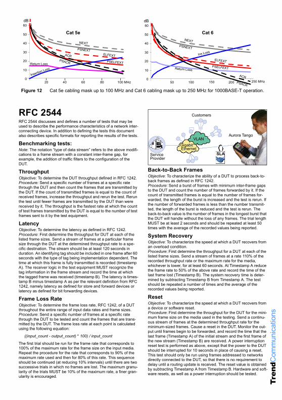
Figure 12 Cat 5e cabling mask up to 100 MHz and Cat 6 cabling mask up to 250 MHz for 1000BASE-T operation.
0
10
20
30
40
50
60
50 100 150 200
NEXTPSNEXT
ELFEXTPSELFEXTReturn Loss
ACR
Ins Loss
PSACR
0
10
20
30
40
50
60
NEXT
PSNEXTELFEXT
PSELFEXT
Insertion Loss
dB
Return Loss
ACRPSACR
20 40 60 80 100 MHz
dB
Cat 5e Cat 6
250 MHz
RFC 2544RFC 2544 discusses and defines a number of tests that may be used to describe the performance characteristics of a network inter-connecting device. In addition to defining the tests this document also describes specific formats for reporting the results of the tests.
Benchmarking tests:Note: The notation “type of data stream” refers to the above modifi-cations to a frame stream with a constant inter-frame gap, for example, the addition of traffic filters to the configuration of the DUT.
ThroughputObjective: To determine the DUT throughput defined in RFC 1242. Procedure: Send a specific number of frames at a specific rate through the DUT and then count the frames that are transmitted by the DUT. If the count of transmitted frames is equal to the count of received frames, increase the throughput and rerun the test. Rerun the test until fewer frames are transmitted by the DUT than were received by it. The throughput is the fastest rate at which the count of test frames transmitted by the DUT is equal to the number of test frames sent to it by the test equipment.
LatencyObjective: To determine the latency as defined in RFC 1242.Procedure: First determine the throughput for DUT at each of the listed frame sizes. Send a stream of frames at a particular frame size through the DUT at the determined throughput rate to a spe-cific destination. The stream should be at least 120 seconds in duration. An identifying tag should be included in one frame after 60 seconds with the type of tag being implementation dependent. The time at which this frame is fully transmitted is recorded (timestamp A). The receiver logic in the test equipment MUST recognize the tag information in the frame stream and record the time at which the tagged frame was received (timestamp B). The latency is times-tamp B minus timestamp A as per the relevant definition from RFC 1242, namely latency as defined for store and forward devices or latency as defined for bit forwarding devices.
Frame Loss RateObjective: To determine the frame loss rate, RFC 1242, of a DUT throughout the entire range of input data rates and frame sizes. Procedure: Send a specific number of frames at a specific rate through the DUT to be tested and count the frames that are trans-mitted by the DUT. The frame loss rate at each point is calculated using the following equation:
((input_count - output_count) * 100) / input_count
The first trial should be run for the frame rate that corresponds to 100% of the maximum rate for the frame size on the input media. Repeat the procedure for the rate that corresponds to 90% of the maximum rate used and then for 80% of this rate. This sequence should be continued (at reducing 10% intervals) until there are two successive trials in which no frames are lost. The maximum granu-larity of the trials MUST be 10% of the maximum rate, a finer gran-ularity is encouraged.
Back-to-Back FramesObjective: To characterize the ability of a DUT to process back-to-back frames as defined in RFC 1242. Procedure: Send a burst of frames with minimum inter-frame gaps to the DUT and count the number of frames forwarded by it. If the count of transmitted frames is equal to the number of frames for-warded, the length of the burst is increased and the test is rerun. If the number of forwarded frames is less than the number transmit-ted, the length of the burst is reduced and the test is rerun. The back-to-back value is the number of frames in the longest burst that the DUT will handle without the loss of any frames. The trial length MUST be at least 2 seconds and should be repeated at least 50 times with the average of the recorded values being reported.
System RecoveryObjective: To characterize the speed at which a DUT recovers from an overload condition. Procedure: First determine the throughput for a DUT at each of the listed frame sizes. Send a stream of frames at a rate 110% of the recorded throughput rate or the maximum rate for the media, whichever is lower, for at least 60 seconds. At Timestamp A reduce the frame rate to 50% of the above rate and record the time of the last frame lost (Timestamp B). The system recovery time is deter-mined by subtracting Timestamp B from Timestamp A. The test should be repeated a number of times and the average of the recorded values being reported.
ResetObjective: To characterize the speed at which a DUT recovers from a device or software reset.Procedure: First determine the throughput for the DUT for the mini-mum frame size on the media used in the testing. Send a continu-ous stream of frames at the determined throughput rate for the minimum-sized frames. Cause a reset in the DUT. Monitor the out-put until frames begin to be forwarded, and record the time that the last frame (Timestamp A) of the initial stream and the first frame of the new stream (Timestamp B) are received. A power interruption reset test is performed as above, except that the power to the DUT should be interrupted for 10 seconds in place of causing a reset. This test should only be run using frames addressed to networks directly connected to the DUT, so that there is no requirement to delay until a routing update is received. The reset value is obtained by subtracting Timestamp A from Timestamp B. Hardware and soft-ware resets, as well as a power interruption should be tested.
Customers
ServiceProvider
SLA
GigabitEthernet
VLANAurora Tango
TrendCommunications
Americas: +1 256 461 0790
España:
UK:
Deutschland:
France:India:
93 300 33 13
01628 524977
089 32 3009-0
01 69 35 54 7022 8597 463/4
web:mail:
Trend Communications Ltd.Knaves Beech EstateLoudwater, High WycombeBuckinghamshire HP10 9QZ UK
© C
opyr
ight
Tre
nd C
omm
unic
atio
ns 2
004
Gigabit Ethernet test, Gigabit Ethernet testing, Gigabit Ethernet installation, Gigabit Ethernet maintenance, Gigabit Ethernet commissioning, Gigabit Ethernet troubleshooting, Gigabit Ethernet protocols, Gigabit Ethernet Alarms, Gigabit Ethernet test, Gigabit Ethernet test, Gigabit Ethernet test, Gigabit Ethernet tester
AcronymsACR Attenuation to Cross Talk Ratio NIC Network Interface Card
Auto Autonegotiation NRZ Non Return to Zero
CPE Customer Premises Equipment PAM Pulse Amplitude Modulation
CSMA/CD Carrier Sense Multiple Access Collision Detect PCS Physical Code Sublayer
DUT Device Under Test PHY Physical Layer
ELFEXT Equal Level Far End Cross Talk PMA Physical Medium Attachment
FDX Full-Duplex Capacity PMD Physical Media Dependent
GMII Gigabit Media Independent Interface PSACR Power Sum ACR
IL Insertion Loss PSELFEXT Power Sum ELFEXT
LLC Logical Link Control (LLC) PSNEX Power Sum Next
MAC Media Access Control (MAC) RL Return Loss
MDI Media-Dependent Interface RZ Return to Zero
MFS Minimum Frame Size RZI Return to Zero Inverted
MII Media-Independent Interface SMF Single Mode Fibre
MLT3 Multi-Level Threshold STP Shielded Twisted Pair
MMF Multi-Mode Fibre UP Unformatted Page
NEXT Near End Cross Talk UTP Unshielded Twisted Pair
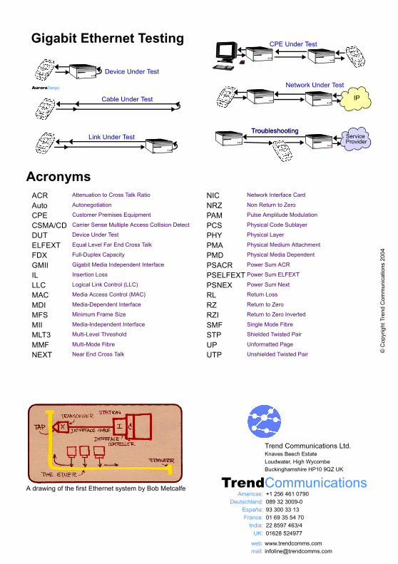
A drawing of the first Ethernet system by Bob Metcalfe
Gigabit Ethernet Testing
Cable Under Test
Link Under Test
Device Under Test
AuroraTango
IP
Network Under Test
ServiceProvider
TroubleshootingTroubleshooting
CPE Under Test


![CCNP BCMSN Quick Reference Sheets - Lagout Quick Reference... · CCNP BCMSN Quick Reference Sheets Exam 642-812 ... [ 4 ] CCNP BCMSN Quick Reference Sheets. ... switch would be used](https://img.pdfslide.us/doc/110x75/5a7a6ec87f8b9a05538dccf5/ccnp-bcmsn-quick-reference-sheets-lagout-quick-referenceccnp-bcmsn-quick-reference.jpg)