Embed Size (px)
Citation preview

737Quick Reference Handbook
Quick Action IndexQA.Index Non-Normal Checklists-IndexABORTED ENGINE START . . . . . . . . . . . . . . . 7.1AIRSPEED UNRELIABLE . . . . . . . . . . . . . . . 10.1APU FIRE . . . . . . . . . . . . . . . . . . . . . . . . . . . . . 8.1CABIN ALTITUDE WARNING OR RAPID DEPRESSURIZATION . . . . . . . . . . . . . . . . . . . 2.3
EMERGENCY DESCENT . . . . . . . . . . . . . . . . . 2.5ENGINE FIRE, SEVERE DAMAGE OR SEPARATION . . . . . . . . . . . . . . . . . . . . . . . . . 8.4
ENGINE LIMIT/SURGE/STALL . . . . . . . . . . . . 7.12ENGINE OVERHEAT . . . . . . . . . . . . . . . . . . . . . 8.6ENGINE TAILPIPE FIRE . . . . . . . . . . . . . . . . . . 8.7EVACUATION . . . . . . . . . . . . . . . . . Back Cover.2FUSELAGE FIRES CLASS B PASS/CARGO OR ALL CARGO . . . . . . . . . . 8.8
FUSELAGE FIRES CLASS E ALL CARGO . . . . . . . . . . . . . . . . . . . . . . . . . . . . . 8.10
OVERSPEED . . . . . . . . . . . . . . . . . . . . . . . . . . 15.1RUNAWAY STABILIZER . . . . . . . . . . . . . . . . . 9.10TAKEOFF CONFIGURATION . . . . . . . . . . . . . 15.1UNCOMMANDED RUDDER/YAW OR ROLL . . . . . . . . . . . . . . . . . . . . . . . . . . . . . . 9.24
D6-27370-200A-TBC QA.Index.1October 9, 2007

Non-Normal Checklists -Index
WARNING HORN - CABIN ALTITUDE OR CONFIGURATION . . . . . . . . . . . . . . . . . 15.2
QA.Index.2 D6-27370-200A-TBC October 9, 2007

Boeing 737 Operations Manual
Annunciated Index Chapter ANNLights List Section Index
Copyright © The Boeing Company. See title page for details.
ANN.Index Annunciated Index-Lights ListAALTITUDE ALERT . . . . . . . . . . . . . . . . . . . . . . . . . . . . . . . . . . . . . . . 15.1ANTISKID INOP . . . . . . . . . . . . . . . . . . . . . . . . . . . . . . . . . . . . . . . . 14.1APU DET INOP . . . . . . . . . . . . . . . . . . . . . . . . . . . . . . . . . . . . . . . 7.1,8.1APU HIGH OIL TEMPERATURE or LOW OIL PRESSURE . . . . . . . . 7.2AUTO BRAKE DISARM . . . . . . . . . . . . . . . . . . . . . . . . . . . . . . . . . . 14.1AUTO FAIL . . . . . . . . . . . . . . . . . . . . . . . . . . . . . . . . . . . . . . . . . . 0.3,2.1AUTO PILOT . . . . . . . . . . . . . . . . . . . . . . . . . . . . . . . . . . . . . . . . . . . . 4.1AUTO UNLK . . . . . . . . . . . . . . . . . . . . . . . . . . . . . . . . . . . . . . . . . . . . 1.1BBLEED TRIP OFF . . . . . . . . . . . . . . . . . . . . . . . . . . . . . . . . . . . . . . . . 2.2BUS OFF . . . . . . . . . . . . . . . . . . . . . . . . . . . . . . . . . . . . . . . . . . . . . . . 6.1CCDS HIGH OIL TEMPERATURE . . . . . . . . . . . . . . . . . . . . . . . . . . . . 6.1CDS LOW OIL PRESSURE . . . . . . . . . . . . . . . . . . . . . . . . . . . . . . . . 6.2COWL VALVE OPEN . . . . . . . . . . . . . . . . . . . . . . . . . . . . . . . . . . . . . 3.1Crossfeed VALVE OPEN . . . . . . . . . . . . . . . . . . . . . . . . . . . . . . . . . . 12.1DDETECTOR FAULT . . . . . . . . . . . . . . . . . . . . . . . . . . . . . . . . . . . . . . . 8.2Door annunciator . . . . . . . . . . . . . . . . . . . . . . . . . . . . . . . . . . . . . . . . . 1.2DUAL BLEED . . . . . . . . . . . . . . . . . . . . . . . . . . . . . . . . . . . . . . . . . . . 2.4DUCT OVERHEAT . . . . . . . . . . . . . . . . . . . . . . . . . . . . . . . . . . . . . . . 2.4EENG 1, 2 OVERHEAT . . . . . . . . . . . . . . . . . . . . . . . . . . . . . . . . . 7.17,8.6Engine LOW OIL PRESSURE . . . . . . . . . . . . . . . . . . . . . . . . . . . . . 7.14Equipment cooling OFF . . . . . . . . . . . . . . . . . . . . . . . . . . . . . . . . . . . . 2.6FFEEL DIFF PRESSURE . . . . . . . . . . . . . . . . . . . . . . . . . . . . . . . . . . . 9.2FILTER ICING . . . . . . . . . . . . . . . . . . . . . . . . . . . . . . . . . . . . . . . . . . 12.4FIRE WARN and APU fire . . . . . . . . . . . . . . . . . . . . . . . . . . . . . . . 7.2,8.1
D6-27370-200A-TBC ANN.Index.1April 9, 2008

Boeing 737 Operations Manual
Annunciated Index -Lights List
Copyright © The Boeing Company. See title page for details.
FIRE WARN and cargo fire . . . . . . . . . . . . . . . . . . . . . . . . . . . . . . . . . 8.2FIRE WARN and engine fire 1, 2 . . . . . . . . . . . . . . . . . . . . . . . . . . 7.6,8.4FIRE WARN and WHEEL WELL fire . . . . . . . . . . . . . . . . . . . . 8.16,14.22Flight control LOW PRESSURE . . . . . . . . . . . . . . . . . . . . . . . . . . . . . 9.2Flight recorder OFF . . . . . . . . . . . . . . . . . . . . . . . . . . . . . . . . . . . . . . 10.1Fuel heat VALVE OPEN . . . . . . . . . . . . . . . . . . . . . . . . . . . . . . . . . . . 12.5Fuel pump LOW PRESSURE . . . . . . . . . . . . . . . . . . . . . . . . . . . . . . 12.6GGround proximity INOP . . . . . . . . . . . . . . . . . . . . . . . . . . . . . . . . . . . 15.1HHydraulic pump LOW PRESSURE . . . . . . . . . . . . . . . . . . . . . . . . . . 13.1Hydraulic pump OVERHEAT . . . . . . . . . . . . . . . . . . . . . . . . . . . . . . . 13.1Hydraulic pumps system A and B LOW PRESSURE . . . . . . . . . . . . 13.8Hydraulic pumps system A LOW PRESSURE . . . . . . . . . . . . . . . . . 13.2Hydraulic pumps system B LOW PRESSURE . . . . . . . . . . . . . . . . . 13.6IISOLATION VALVE . . . . . . . . . . . . . . . . . . . . . . . . . . . . . . . . . . . . . . 7.28LL, R VALVE OPEN . . . . . . . . . . . . . . . . . . . . . . . . . . . . . . . . . . . . . . . . 3.2LE FLAPS TRANSIT . . . . . . . . . . . . . . . . . . . . . . . . . . . . . . . . . . . . . . 9.6LOCK FAIL . . . . . . . . . . . . . . . . . . . . . . . . . . . . . . . . . . . . . . . . . . . . . . 1.5MMACH TRIM FAIL . . . . . . . . . . . . . . . . . . . . . . . . . . . . . . . . . . . . . . . . 9.9NNOT ARMED . . . . . . . . . . . . . . . . . . . . . . . . . . . . . . . . . . . . . . . . . . . . 1.5OOFF SCHED DESCENT . . . . . . . . . . . . . . . . . . . . . . . . . . . . . . . . . . . 2.6OIL FILTER BYPASS . . . . . . . . . . . . . . . . . . . . . . . . . . . . . . . . . . . . . 7.16OVERSPEED . . . . . . . . . . . . . . . . . . . . . . . . . . . . . . . . . . . . . . . . . . . 7.3PPACK TRIP OFF . . . . . . . . . . . . . . . . . . . . . . . . . . . . . . . . . . . . . . . . . 2.8PASS OXY ON . . . . . . . . . . . . . . . . . . . . . . . . . . . . . . . . . . . . . . . . . . 1.5
ANN.Index.2 D6-27370-200A-TBC April 9, 2008

Boeing 737 Operations Manual
Annunciated Index -Lights List
Copyright © The Boeing Company. See title page for details.
Pitot static . . . . . . . . . . . . . . . . . . . . . . . . . . . . . . . . . . . . . . . . . . . . . . 3.1RREVERSER UNLOCKED . . . . . . . . . . . . . . . . . . . . . . . . . . . . . . . . . 7.26SSPEED BRAKE DO NOT ARM . . . . . . . . . . . . . . . . . . . . . . . . . . . . . 9.10STAB OUT OF TRIM . . . . . . . . . . . . . . . . . . . . . . . . . . . . . . . . . . . . . 9.11Standby hydraulic LOW PRESSURE . . . . . . . . . . . . . . . . . . . . . . . 13.11Standby hydraulic LOW QUANTITY . . . . . . . . . . . . . . . . . . . . . . . . 13.11STANDBY PWR OFF . . . . . . . . . . . . . . . . . . . . . . . . . . . . . . . . . . . . . 6.7START VALVE OPEN . . . . . . . . . . . . . . . . . . . . . . . . . . . . . . . . . . . . 7.22STBY RUD ON . . . . . . . . . . . . . . . . . . . . . . . . . . . . . . . . . . . . . . . . . 9.14TTAKEOFF CONFIG . . . . . . . . . . . . . . . . . . . . . . . . . . . . . . . . . . . . . . 15.1TRANSFER BUS OFF . . . . . . . . . . . . . . . . . . . . . . . . . . . . . . . . . . . . 6.7TRANSFER BUS OFF, BUS OFF and GEN BUS OFF . . . . . . . . . . . . 6.4WWindow OVERHEAT . . . . . . . . . . . . . . . . . . . . . . . . . . . . . . . . . . . . . . 3.2WING-BODY OVERHEAT . . . . . . . . . . . . . . . . . . . . . . . . . . . . . . . . . 2.10YYAW DAMPER . . . . . . . . . . . . . . . . . . . . . . . . . . . . . . . . . . . . . . . . . 9.29
D6-27370-200A-TBC ANN.Index.3April 9, 2008

Boeing 737 Operations Manual
Annunciated Index -Lights List
Copyright © The Boeing Company. See title page for details.
IntentionallyBlank
ANN.Index.4 D6-27370-200A-TBC April 9, 2008

Boeing 737 Operations Manual
Normal Checklists Chapter NC
Copyright © The Boeing Company. See title page for details.
NC. Normal Checklists- PREFLIGHT
Oxygen . . . . . . . . . . . . . . . . . . . . . . . . . . . . . . . . . Tested, 100%Navigation and instrument transfer switches . . . . . . . . . . . . . . . . . . NORMALWindow heat . . . . . . . . . . . . . . . . . . . . . . . . . . . . . . . . . . . . . .ONPressurization mode selector . . . . . . . . . . . . . . . . . . . . . AUTOFlight instruments . . . . . . . . . . . . . Heading___, Altimeter___Parking brake . . . . . . . . . . . . . . . . . . . . . . . . . . . . . . . . . . . . .SetEngine start levers . . . . . . . . . . . . . . . . . . . . . . . . . . . . CUTOFF
BEFORE STARTFlight deck door . . . . . . . . . . . . . . . . . . . . . Closed and lockedFuel . . . . . . . . . . . . . . . . . . . . . . . . . . . . . . ___ LBS, Pumps ONPassenger signs. . . . . . . . . . . . . . . . . . . . . . . . . . . . . . . . . . ___Gravel protect (as installed) . . . . . . . . . . . . . . . . . . . . . . . . ___Windows . . . . . . . . . . . . . . . . . . . . . . . . . . . . . . . . . . . . . LockedHSI . . . . . . . . . . . . . . . . . . . . . . . . . . . . . . . . . . . . . . Heading___Altitude alert . . . . . . . . . . . . . . . . . . . . . . . . . . . . . . .Altitude___Takeoff speeds . . . . . . . . . . . . . . . . . . . . V1___, VR___, V2___PDCS preflight (as installed) . . . . . . . . . . . . . . . . . . CompletedRudder and aileron trim. . . . . . . . . . . . . . . . . . . . . . Free and 0Taxi and takeoff briefing . . . . . . . . . . . . . . . . . . . . . CompletedANTI COLLISION light . . . . . . . . . . . . . . . . . . . . . . . . . . . . . .ON
D6-27370-200A-TBC NC.1April 9, 2008

Boeing 737 Operations Manual
Normal Checklists
Copyright © The Boeing Company. See title page for details.
BEFORE TAXIGenerators . . . . . . . . . . . . . . . . . . . . . . . . . . . . . . . . . . . . . . OnPitot heat . . . . . . . . . . . . . . . . . . . . . . . . . . . . . . . . . . . . . . . . .ONAnti-ice . . . . . . . . . . . . . . . . . . . . . . . . . . . . . . . . . . . . . . . . . ___Isolation valve . . . . . . . . . . . . . . . . . . . . . . . . . . . . . . . . . AUTOEngine start switches . . . . . . . . . . . . . . . . . . . . . . . . .LOW IGNRecall . . . . . . . . . . . . . . . . . . . . . . . . . . . . . . . . . . . . . . CheckedAutobrake . . . . . . . . . . . . . . . . . . . . . . . . . . . . . . . . . . . . . . . OFFEngine start levers . . . . . . . . . . . . . . . . . . . . . . . . . IDLE detentFlight controls . . . . . . . . . . . . . . . . . . . . . . . . . . . . . . . CheckedGround equipment . . . . . . . . . . . . . . . . . . . . . . . . . . . . . . . Clear
BEFORE TAKEOFFFlaps . . . . . . . . . . . . . . . . . . . . . . . . . . . . . . . . . ___, Green lightStabilizer trim . . . . . . . . . . . . . . . . . . . . . . . . . . . . . . . ___ Units
AFTER TAKEOFFEngine bleeds. . . . . . . . . . . . . . . . . . . . . . . . . . . . . . . . . . . . .ONPacks. . . . . . . . . . . . . . . . . . . . . . . . . . . . . . . . . . . . . . . . . . . .ONLanding gear . . . . . . . . . . . . . . . . . . . . . . . . . . . . . UP and OFFFlaps . . . . . . . . . . . . . . . . . . . . . . . . . . . . . . . . . . . UP, No lights
DESCENTPressurization . . . . . . . . . . . . . . CAB ALT ___, LAND ALT ___Gravel protect (as installed) . . . . . . . . . . . . . . . . . . . . . . . . ___Recall . . . . . . . . . . . . . . . . . . . . . . . . . . . . . . . . . . . . . . CheckedAutobrake . . . . . . . . . . . . . . . . . . . . . . . . . . . . . . . . . . . . . . . ___Landing data . . . . . . . . . . . . . . . . . . . .VREF___, Minimums___Approach briefing . . . . . . . . . . . . . . . . . . . . . . . . . . Completed
NC.2 D6-27370-200A-TBC April 9, 2008

Boeing 737 Operations Manual
Normal Checklists
Copyright © The Boeing Company. See title page for details.
APPROACHAltimeters . . . . . . . . . . . . . . . . . . . . . . . . . . . . . . . . . . . . . . . ___
LANDINGEngine start switches . . . . . . . . . . . . . . . . . . . . . . . . LOW IGNSpeedbrake . . . . . . . . . . . . . . . . . . . . . . . . . . . . . . . . . . . ARMEDLanding gear. . . . . . . . . . . . . . . . . . . . . . . . . . . . . . . . . . . DownFlaps . . . . . . . . . . . . . . . . . . . . . . . . . . . . . . . . . ___, Green light
SHUTDOWNFuel pumps . . . . . . . . . . . . . . . . . . . . . . . . . . . . . . . . . . . . . . OFFPitot heat . . . . . . . . . . . . . . . . . . . . . . . . . . . . . . . . . . . . . . . . OFFHydraulic panel . . . . . . . . . . . . . . . . . . . . . . . . . . . . . . . . . . .SetFlaps . . . . . . . . . . . . . . . . . . . . . . . . . . . . . . . . . . . . . . . . . . . . UPParking brake . . . . . . . . . . . . . . . . . . . . . . . . . . . . . . . . . . . . ___Engine start levers . . . . . . . . . . . . . . . . . . . . . . . . . . . . CUTOFFWeather radar . . . . . . . . . . . . . . . . . . . . . . . . . . . . . . . . . . . . OFF
SECUREEmergency exit lights . . . . . . . . . . . . . . . . . . . . . . . . . . . . . OFFWindow heat . . . . . . . . . . . . . . . . . . . . . . . . . . . . . . . . . . . . . OFFPacks . . . . . . . . . . . . . . . . . . . . . . . . . . . . . . . . . . . . . . . . . . . OFF
D6-27370-200A-TBC NC.3April 9, 2008

Boeing 737 Operations Manual
Normal Checklists
Copyright © The Boeing Company. See title page for details.
IntentionallyBlank
NC.4 D6-27370-200A-TBC April 9, 2008

Boeing 737 Operations Manual
Checklist Introduction Chapter CITable of Contents Section 0
Copyright © The Boeing Company. See title page for details.
CI.0 Checklist Introduction-Table of Contents
Normal Checklists . . . . . . . . . . . . . . . . . . . . . . . . . . . . . . . . . . . . . CI.1.1
Introduction . . . . . . . . . . . . . . . . . . . . . . . . . . . . . . . . . . . . . . . . . CI.1.1Normal Checklist Operation . . . . . . . . . . . . . . . . . . . . . . . . . . . . CI.1.1Checklist Content . . . . . . . . . . . . . . . . . . . . . . . . . . . . . . . . . . . . . CI.1.2Checklist Construction . . . . . . . . . . . . . . . . . . . . . . . . . . . . . . . . . CI.1.2
Non-Normal Checklists . . . . . . . . . . . . . . . . . . . . . . . . . . . . . . . . CI.2.1
Introduction . . . . . . . . . . . . . . . . . . . . . . . . . . . . . . . . . . . . . . . . . CI.2.1Non-Normal Checklist Operation . . . . . . . . . . . . . . . . . . . . . . . . CI.2.1Non–Normal Checklist Use . . . . . . . . . . . . . . . . . . . . . . . . . . . . . CI.2.4
D6-27370-200A-TBC CI.TOC.0.1October 9, 2007

Boeing 737 Operations Manual
Checklist Introduction -Table of Contents
Copyright © The Boeing Company. See title page for details.
IntentionallyBlank
CI.TOC.0.2 D6-27370-200A-TBC October 9, 2007

Boeing 737 Operations Manual
Checklist Introduction Chapter CINormal Checklists Section 1
Copyright © The Boeing Company. See title page for details.
CI.1 Checklist Introduction-Normal ChecklistsIntroductionThis introduction gives guidelines for use of the Normal Checklist (NC).The NC is organized by phase of flight. The NC is used to verify that critical items have been done.
Normal Checklist OperationNormal checklists are used after doing all respective procedural items.The following table shows which pilot calls for the checklist and which pilot reads the checklist. Both pilots visually verify that each item is in the needed configuration or that the step is done. The far right column shows which pilot gives the response. This is different than the normal procedures where the far right column can show which pilot does the step.
If the airplane configuration does not agree with the needed configuration:• stop the checklist• complete the respective procedure steps• continue the checklist
If it becomes apparent that an entire procedure was not done:• stop the checklist• complete the entire procedure• do the checklist from the start
Checklist Call Read Verify Respond
PREFLIGHT Captain First officer Both Area of responsibility
BEFORE START Captain First officer Both Area of responsibility
BEFORE TAXI Captain First officer Both Area of responsibility
BEFORE TAKEOFF Pilot flying Pilot monitoring Both Pilot flying
AFTER TAKEOFF Pilot flying Pilot monitoring Both Pilot monitoring
DESCENT Pilot flying Pilot monitoring Both Area of responsibility
APPROACH Pilot flying Pilot monitoring Both Area of responsibility
LANDING Pilot flying Pilot monitoring Both Pilot flying
SHUTDOWN Captain First officer Both Area of responsibility
SECURE Captain First officer Both Area of responsibility
D6-27370-200A-TBC CI.1.1April 1, 2005

Boeing 737 Operations Manual
Checklist Introduction -Normal Checklists
Copyright © The Boeing Company. See title page for details.
Try to do checklists before or after high work load times. The crew may need to stop a checklist for a short time to do other tasks. If the interruption is short, continue the checklist with the next step. If a pilot is not sure where the checklist was stopped, do the checklist from the start. If the checklist is stopped for a long time, also do the checklist from the start.After completion of each checklist, the pilot reading the checklist calls, “________ CHECKLIST COMPLETE.”
Checklist ContentThe checklist has the minimum items needed to operate the airplane safely.Normal checklists have items that meet any of the following criteria:• items essential to safety of flight that are not monitored by an alerting
system, or• items essential to safety of flight that are monitored by an alerting system
but if not done, would likely result in a catastrophic event if the alerting system fails, or
• items needed to meet regulatory requirements, or• items needed to maintain fleet commonality between the 737, 747-400,
757, 767, and 777, or• items that enhance safety of flight and are not monitored by an alerting
system (for example autobrakes), or• during shutdown and secure, items that could result in injury to personnel
or damage to equipment if not done
Checklist ConstructionWhen a checklist challenge does not end with “switch or lever”, then the challenge refers to system status. For example, “Landing Gear...Down”, refers to the status of the landing gear, not just the position of the lever.When a checklist challenge ends with “switch or lever”, then the challenge refers to the position of the switch or lever. For example, “Engine start levers...CUTOFF” refers to the position of the levers.
CI.1.2 D6-27370-200A-TBC April 9, 2008

Boeing 737 Operations Manual
Checklist Introduction Chapter CINon-Normal Checklists Section 2
Copyright © The Boeing Company. See title page for details.
CI.2 Checklist Introduction-Non-Normal ChecklistsIntroductionThe Non-Normal Checklists chapter contains checklists used by the flight crew to cope with non–normal situations. The checklists are grouped in logical sections which match the system description chapters in Volume 2. The checklists are in alphabetical order in each section.Most checklists correspond to a Master Caution and System Annunciator light. The Master Caution and System Annunciator indicate a failure condition and are the cues to select and do the checklist.Checklists without a Master Caution and System Annunciator light (such as DITCHING) are called unannunciated checklists. All unannunciated checklists are found in the first section of the Non–Normal Checklists chapter. Some unannunciated checklists also appear in the respective systems section (such as ENGINE FUEL LEAK in the Fuel section).A condition statement is given for all non-normal checklists. The condition statement briefly describes the condition which caused the Master Caution to illuminate. Unannunciated checklists also have condition statements to help in understanding the reason for the checklist.Checklists can have both recall and reference items. Recall items are critical steps that must be done from memory and are placed within a box. Reference items are actions to be done while reading the checklist. In the Table of Contents for each non-normal checklist section, the titles of checklists containing recall items are printed in bold type.Some amplified information is included in brackets [ ] in the printed non–normal checklist when the reason for an item is not obvious.
Non-Normal Checklist OperationNon–normal checklists start with steps to correct the situation or condition. Information for planning the rest of the flight is included. When special items are needed to configure the airplane for landing, the items are deferred to the Approach or Landing checklist. Flight patterns for some non–normal situations are located in the Maneuvers chapter and show the sequence of configuration changes.
D6-27370-200A-TBC CI.2.1October 9, 2007

Boeing 737 Operations Manual
Checklist Introduction -Non-Normal Checklists
Copyright © The Boeing Company. See title page for details.
While every attempt is made to provide needed non–normal checklists, it is not possible to develop checklists for all conceivable situations, especially those involving multiple failures. In some unrelated multiple failure situations, the flight crew may combine elements of more than one checklist or exercise judgment to determine the safest course of action. The captain must assess the situation and use good judgment to determine the safest course of action.In some cases the crew may need to move between two checklists. For example, for unannunciated smoke, fire or fumes, the crew starts with the SMOKE, FIRE OR FUMES checklist. The crew must quickly do the initial steps that provide for crew safety and isolate potential sources of the problem. The procedure then states: “Anytime the smoke or fumes becomes the greatest threat, do the SMOKE/FUMES REMOVAL checklist.” This statement allows the crew to use judgement in determining when to do the related SMOKE/FUMES REMOVAL checklist.There are some situations where the crew must always land at the nearest suitable airport. These situations include, but are not limited to, conditions where:• the non–normal checklist has the words “Plan to land at the nearest
suitable airport”• cabin smoke or fire persists• one main AC power source remains (such as engine or APU generator)• one hydraulic system remains (the standby system is considered a
hydraulic system)• any other situation determined by the crew to have a significant adverse
effect on safety if the flight is continuedIt must be stressed that for persistent smoke or a fire that cannot be positively confirmed to be completely extinguished, the earliest possible descent, landing, and passenger evacuation must be done.If a smoke, fire or fumes condition becomes uncontrollable, the SMOKE, FIRE OR FUMES checklist directs the flight crew to consider an immediate landing. “Immediate landing” implies immediate diversion to a runway. However, the smoke, fire or fumes may be severe enough that the captain should consider an overweight landing, a tailwind landing, an off-airport landing, or a ditching.Checklists prescribing an engine shutdown must be evaluated by the captain to determine whether an actual shutdown or operation at reduced thrust is the safest course of action. Consideration must be given to probable effects if the engine is operated at the minimum needed thrust.There are no non-normal checklists associated with the loss of an engine indication. Operate the engine normally unless a limit is exceeded.
CI.2.2 D6-27370-200A-TBC October 9, 2007
Boeing 737 Operations Manual
Checklist Introduction -Non-Normal Checklists
Copyright © The Boeing Company. See title page for details.
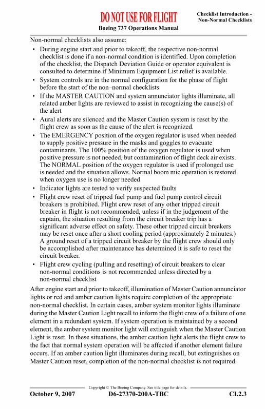
Non-normal checklists also assume:• During engine start and prior to takeoff, the respective non-normal
checklist is done if a non-normal condition is identified. Upon completion of the checklist, the Dispatch Deviation Guide or operator equivalent is consulted to determine if Minimum Equipment List relief is available.
• System controls are in the normal configuration for the phase of flight before the start of the non–normal checklists.
• If the MASTER CAUTION and system annunciator lights illuminate, all related amber lights are reviewed to assist in recognizing the cause(s) of the alert
• Aural alerts are silenced and the Master Caution system is reset by the flight crew as soon as the cause of the alert is recognized.
• The EMERGENCY position of the oxygen regulator is used when needed to supply positive pressure in the masks and goggles to evacuate contaminants. The 100% position of the oxygen regulator is used when positive pressure is not needed, but contamination of flight deck air exists. The NORMAL position of the oxygen regulator is used if prolonged use is needed and the situation allows. Normal boom mic operation is restored when oxygen use is no longer needed
• Indicator lights are tested to verify suspected faults• Flight crew reset of tripped fuel pump and fuel pump control circuit
breakers is prohibited. Flight crew reset of any other tripped circuit breaker in flight is not recommended, unless if in the judgement of the captain, the situation resulting from the circuit breaker trip has a significant adverse effect on safety. These other tripped circuit breakers may be reset once after a short cooling period (approximately 2 minutes.) A ground reset of a tripped circuit breaker by the flight crew should only be accomplished after maintenance has determined it is safe to reset the circuit breaker.
• Flight crew cycling (pulling and resetting) of circuit breakers to clear non-normal conditions is not recommended unless directed by a non-normal checklist
After engine start and prior to takeoff, illumination of Master Caution annunciator lights or red and amber caution lights require completion of the appropriate non-normal checklist. In certain cases, amber system monitor lights illuminate during the Master Caution Light recall to inform the flight crew of a failure of one element in a redundant system. If system operation is maintained by a second element, the amber system monitor light will extinguish when the Master Caution Light is reset. In these situations, the amber caution light alerts the flight crew to the fact that normal system operation will be affected if another element failure occurs. If an amber caution light illuminates during recall, but extinguishes on Master Caution reset, completion of the non-normal checklist is not required.
D6-27370-200A-TBC CI.2.3October 9, 2007

Boeing 737 Operations Manual
Checklist Introduction -Non-Normal Checklists
Copyright © The Boeing Company. See title page for details.
Each air carrier has the responsibility of establishing flight crew procedures in the event of a system failure after the aircraft has departed the gate or the parking area for the purpose of takeoff.
Non–Normal Checklist UseNon–normal checklist use starts when the airplane flight path and configuration are correctly established. Only a few situations need an immediate response (such as a stall warning, ground proximity PULL UP and WINDSHEAR warnings, or a rejected takeoff.) Usually, time is available to assess the situation before corrective action is started. All actions must then be coordinated under the captain's supervision and done in a deliberate, systematic manner. Flight path control must never be compromised.When a non-normal situation occurs, at the direction of the pilot flying, both crew members systematically and without delay do all recall items in their areas of responsibility.The pilot flying calls for the checklist when:• the flight path is under control• the airplane is not in a critical stage of flight (such as takeoff or landing)• all recall items are complete.
For those checklists with only recall items or a combination of recall and reference items, the pilot monitoring first verifies each recall item has been done. The checklist is normally read aloud during such verification. The pilot flying does not need to respond except for items not in agreement with the checklist. However, in the non-normal landing checklist the pilot flying verifies and responds to checklist items.The checklist title and reference items, including the response or action and any amplifying information, are read aloud by the pilot monitoring. Read aloud as much of the condition statement as needed to verify the selection of the correct checklist. Information appearing in brackets does not need to be read aloud. The pilot flying need not repeat these items, but must acknowledge that the items were heard and understood. After moving the control, the crewmember taking the action also states the checklist response. Action is taken by the pilot flying and pilot monitoring based on the crewmember’s area of responsibility. With the airplane stationary on the ground, action is taken by the captain as pilot flying and the first officer as pilot monitoring based on preflight area of responsibility.Both pilots must agree before moving critical controls in flight, such as:• the thrust lever of a failed engine• an engine start lever• an engine, APU or cargo fire switch (as installed)
CI.2.4 D6-27370-200A-TBC October 9, 2007

Boeing 737 Operations Manual
Checklist Introduction -Non-Normal Checklists
Copyright © The Boeing Company. See title page for details.
• a generator drive disconnect switch• a flight control or spoiler switch.
The pilot flying may also direct reference procedures to be done by recall if no hazard is created by such action, or if the situation does not allow reference to a checklist.Checklists show lists of inoperative equipment only when knowledge of the condition of such equipment is essential for planning the rest of the flight.The pilot flying is to be made aware when there are deferred items. These items may be delayed until the usual point during approach or landing.Following completion of the applicable non–normal checklist items, normal checklists are used to verify that the configuration is correct for each phase of flight.Pilots must be aware that checklists cannot be created for all conceivable situations and are not intended to replace good judgment. In some conditions, deviation from checklists may, at the captain’s discretion, be needed.The following symbol shows that the checklist is complete.
Each checklist has a checklist complete symbol at the end. The checklist complete symbol can also be in the body of the checklist. This occurs only when a checklist divides into two or more paths. Each path can have a checklist complete symbol. The checklist complete symbol shows the end of the applicable path. The crew need not continue the checklist after that point.Following completion of each non–normal checklist, the pilot monitoring states: “_______ CHECKLIST COMPLETE.” When a non–normal checklist is complete except for the deferred items, and the normal checklist to which the items have been deferred has not yet been done, the pilot monitoring states: “______ CHECKLIST COMPLETE EXCEPT FOR DEFERRED ITEMS.”
D6-27370-200A-TBC CI.2.5October 9, 2007

Boeing 737 Operations Manual
Checklist Introduction -Non-Normal Checklists
Copyright © The Boeing Company. See title page for details.
IntentionallyBlank
CI.2.6 D6-27370-200A-TBC April 7, 2006

Boeing 737 Operations Manual
Non-Normal Checklists Chapter NNCUnannunciated Checklists Section 0
Copyright © The Boeing Company. See title page for details.
Table of ContentsNNC.0 Non-Normal Checklists-Unannunciated ChecklistsABORTED ENGINE START . . . . . . . . . . . . . . . . . . . . . . . . . . . . 0.1
AIRSPEED UNRELIABLE . . . . . . . . . . . . . . . . . . . . . . . . . . . . . . 0.2AUTO FAIL/UNSCHEDULED PRESSURIZATION
CHANGE . . . . . . . . . . . . . . . . . . . . . . . . . . . . . . . . . . . . . . . . . . . 0.3CABIN ALTITUDE WARNING OR
RAPID DEPRESSURIZATION . . . . . . . . . . . . . . . . . . . . . . . . 0.4DITCHING . . . . . . . . . . . . . . . . . . . . . . . . . . . . . . . . . . . . . . . . . . . . 0.5EMERGENCY DESCENT . . . . . . . . . . . . . . . . . . . . . . . . . . . . . . 0.8ENGINE FUEL LEAK . . . . . . . . . . . . . . . . . . . . . . . . . . . . . . . . . . 0.10ENGINE IN-FLIGHT START . . . . . . . . . . . . . . . . . . . . . . . . . . . . 0.12JAMMED OR RESTRICTED FLIGHT CONTROLS . . . . . . . . . 0.14RADIO TRANSMIT CONTINUOUS (STUCK
MICROPHONE SWITCH) . . . . . . . . . . . . . . . . . . . . . . . . . . . . . 0.16SMOKE, FIRE OR FUMES . . . . . . . . . . . . . . . . . . . . . . . . . . . . . . 0.18SMOKE OR FUMES REMOVAL . . . . . . . . . . . . . . . . . . . . . . . . . 0.20STABILIZER TRIM INOPERATIVE . . . . . . . . . . . . . . . . . . . . . . 0.22TAILSTRIKE ON TAKEOFF . . . . . . . . . . . . . . . . . . . . . . . . . . . . 0.24UNCOMMANDED RUDDER/YAW OR ROLL . . . . . . . . . . . . 0.26VOLCANIC ASH . . . . . . . . . . . . . . . . . . . . . . . . . . . . . . . . . . . . . . 0.30WARNING HORN -CABIN ALTITUDE OR
CONFIGURATION . . . . . . . . . . . . . . . . . . . . . . . . . . . . . . . . . 0.32WINDOW DAMAGE . . . . . . . . . . . . . . . . . . . . . . . . . . . . . . . . . . 0.34WINDOW OPEN . . . . . . . . . . . . . . . . . . . . . . . . . . . . . . . . . . . . . . 0.38
D6-27370-200A-TBC TOC.0.1April 9, 2008

Boeing 737 Operations Manual
Non-Normal Checklists -Unannunciated Checklists
Copyright © The Boeing Company. See title page for details.
IntentionallyBlank
TOC.0.2 D6-27370-200A-TBC April 9, 2008

Boeing 737 Operations Manual 0.1
Copyright © The Boeing Company. See title page for details.
NNC.0 Non-Normal Checklists-Unannunciated
Condition: During a ground start, an abort engine start condition occurs.
If the ENGINE START switch is in GRD:
Motor the engine for 20 seconds.
ENGINE START switch . . . . . . . . . . . . . . . . . . . . . . . . . . OFF
If the ENGINE START switch is in OFF:
After N2 decreases to 0%:
ENGINE START switch . . . . . . . . . . . . . . . . . . . . . . . GRD
Motor the engine for 20 seconds.
ENGINE START switch . . . . . . . . . . . . . . . . . . . . . . . . OFF
ABORTED ENGINE START
Engine start lever . . . . . . . . . . . . . . . . . . . . . . . . . . . . . CUTOFF
D6-27370-200A-TBC 0.1April 9, 2008

Boeing 737 Operations Manual 0.2
Copyright © The Boeing Company. See title page for details.
Condition: Pitch attitude not consistent with existing phase of flight, altitude, thrust, and weight, or noise and/or low frequency buffeting.
Note: Erroneous or unreliable airspeed indications may be caused by blocked or frozen pitot-static system(s), or a severely damaged or missing radome.
Attitude and thrust information is provided in the Performance-Inflight section.
AIRSPEED UNRELIABLE
AIRPLANE ATTITUDE/THRUST . . . . . . . . . . . . . . . . . . ADJUSTMaintain airplane control.
PITOT STATIC HEAT. . . . . . . . . . . . . . . . . . . . . . . . .CHECK ON
MACH/AIRSPEED INDICATORS . . . . . . . . . . . CROSS CHECK
D6-27370-200A-TBC0.2 April 9, 2008

Boeing 737 Operations Manual 0.3
Copyright © The Boeing Company. See title page for details.
Condition: Automatic pressurization mode has failed or the cabin altitude is not under control.
Increasing thrust may ensure adequate air supply to control cabin altitude.ENGINE BLEED AIR SWITCHES . . . . . . .ON (ONE AT A TIME)
PACK SWITCHES . . . . . . . . . . . . . . . . . . .ON (ONE AT A TIME)Allow cabin rate to stabilize before placing second switch on.
If the AUTO FAIL light is illuminated or pressurization is not under control:
PRESSURIZATION MODE SELECTOR. . . . . . . . . . . . .STBYVerify AUTO FAIL light extinguishes.
If the AUTO FAIL light remains illuminated or the STBY mode cannot maintain cabin pressurization:
PRESSURIZATION MODE SELECTOR . . . . . . . . . . MAN
OUTFLOW VALVE SWITCH . . . . . . . . . . . AS REQUIREDOperate the outflow valve to maintain proper cabin altitude and cabin rate of change.At traffic pattern altitude, position the outflow valve to full open.
AUTO FAIL/UNSCHEDULED PRESSURIZATION CHANGE
D6-27370-200A-TBC 0.3April 9, 2008

Boeing 737 Operations Manual 0.4
Copyright © The Boeing Company. See title page for details.
Condition: One or more of the following conditions:• The intermittent cabin altitude/configuration
warning horn sounds and the CABIN ALTITUDE light (as installed) illuminates in flight
• There is a rapid loss of cabin pressure with airplane altitude above 14,000 feet.
CABIN ALTITUDE WARNING OR RAPID DEPRESSURIZATION
Oxygen masks and regulators . . . . . . . . . . . . . . . . . On, 100%
Crew communications . . . . . . . . . . . . . . . . . . . . . . . . Establish
Pressurization mode selector . . . . . . . . . . . . . . . . . . . . . . MAN
Outflow valve switch . . . . . . . . . . . . . . . . . . . . . . . . . . . CLOSEIf pressurization is restored, continue manual operation to maintain proper cabin altitude.
Passenger signs. . . . . . . . . . . . . . . . . . . . . . . . . . . . . . . . . . .ON
If cabin altitude is uncontrollable:
Passenger oxygen switch . . . . . . . . . . . . . . . . . . . . . . . .ONActivate passenger oxygen if cabin altitude exceeds or is expected to exceed 14,000 feet.
Emergency descent . . . . . . . . . . . . . . . . . . . . . . . . . .InitiateAccomplish the EMERGENCY DESCENT checklist if the airplane is above 14,000 feet MSL and control of cabin pressure is not possible, or cabin pressure is lost.
D6-27370-200A-TBC0.4 April 9, 2008
Boeing 737 Operations Manual 0.5
Copyright © The Boeing Company. See title page for details.
Condition: Airplane ditching and evacuation are required.
Send distress signals. Determine position, course, speed, altitude, situation, intention, time and position of intended touchdown and transmit mayday. Report type of aircraft and request intercept.Alert cabin crew to prepare for ditching and seat passengers as far forward as possible.Burn off fuel to reduce touchdown speed and increase buoyancy.Plan to touch down on the windward side and parallel to waves and swells.Plan a flaps 40 landing unless other configuration is required.
Continued on next page
DITCHING
D6-27370-200A-TBC 0.5April 9, 2008

Boeing 737 Operations Manual 0.6
Copyright © The Boeing Company. See title page for details.
Continued from previous page----------------------------DEFERRED ITEMS ------------------------------==> BELOW 5000 FEET
AURAL WARN C/B (P6) . . . . . . . . . . . . . . . . . . . . . . . . . . .PULL[Prevents warning horn with gear retracted and landing flaps selected.]
PASSENGER SIGNS . . . . . . . . . . . . . . . . . . . . . . . . . . . . . . .ON
ENGINE BLEED AIR SWITCHES . . . . . . . . . . . . . . . . . . . . . OFF[Permits depressurizing the airplane with outflow valve closed.]
PRESSURIZATION MODE SELECTOR . . . . . . . . . . . . MAN DC
OUTFLOW VALVE SWITCH . . . . . . . . . . . . . . . . . . . . . . CLOSE[Prevents water from entering the airplane.]
APU SWITCH . . . . . . . . . . . . . . . . . . . . . . . . . . . . . . . . . . . . OFF
GROUND PROXIMITY FLAP/GEARINHIBIT SWITCH. . . . . . . . . . . . . . . . . . . . FLAP/GEAR INHIBIT
LIFE VESTS, SHOULDER HARNESSES AND SEAT BELTS . . . . . . . . . . . . . . . . . . . . . . . . . . . . . . . . .ON
PASSENGER CABIN PREPARATION . . . . . . . . . . COMPLETEConfirm that passenger cabin preparations are complete.
CAUTION: Do not open aft entry or service doors when in all cargo or all passenger operation as they may be partially submerged. During mixed cargo/passenger operation, the aft doors are usable.
FINAL POSITION . . . . . . . . . . . . . . . . . . . . . . . . . . . TRANSMITTransmit all pertinent information regarding final ditching position.
Continued on next page
D6-27370-200A-TBC0.6 April 9, 2008

Boeing 737 Operations Manual 0.7
Copyright © The Boeing Company. See title page for details.
Continued from previous page
Review After Impact Procedure:• Engine start levers to CUTOFF. Closes fuel shutoff valves
to prevent discharge of fuel from ruptured fuel lines.• Initiate evacuation. • Proceed to assigned ditching stations, launch rafts and
evacuate the airplane as soon as practicable. The airplane may remain afloat indefinitely if fuel load is minimal and no serious damage was sustained during landing.
----------------------------DEFERRED ITEMS ------------------------------==> DITCHING FINAL
Omit normal LANDING checklist.LANDING GEAR . . . . . . . . . . . . . . . . . . . . . . . . . . . . . UP & OFF
FLAPS . . . . . . . . . . . . . . . . . . . . . . . . . . . _____, GREEN LIGHT
Advise cabin crew, at 500 feet, ditching is imminent; at 50 feet, brace for impact.Maintain airspeed at VREF. Flare airplane to achieve minimum rate of descent at touchdown. Maintain 200-300 fpm rate of descent until start of flare. At flare, rotate smoothly to touchdown attitude of 10-12 degrees, maintaining desired airspeed and rate of descent with thrust. At touchdown, reduce thrust to idle.
D6-27370-200A-TBC 0.7April 9, 2008

Boeing 737 Operations Manual 0.8
Copyright © The Boeing Company. See title page for details.
Condition: Unable to control cabin pressure with airplane above 14,000 feet MSL or conditions require a rapid descent.
Speedbrake . . . . . . . . . . . . . . . . . . . . . . . . . . . . . . DOWN detentSmoothly lower the SPEED BRAKE lever and level off. Add thrust and stabilize on altitude at desired airspeed.
Crew oxygen regulators . . . . . . . . . . . . . . . . . . . . . . .NORMALFlight crew must use oxygen when cabin altitude is above 10,000 feet. To conserve oxygen, position the NORMAL/100% selector to NORMAL.
ENGINE START switches . . . . . . . . . . . . . . . . . . . . As needed
The new course of action is based on weather, oxygen, fuel remaining and available airports. Use of long range cruise may be appropriate.
EMERGENCY DESCENT
Emergency Descent . . . . . . . . . . . . . . . . . . . . . . . . . .AnnounceThe captain will advise the cabin crew, on the PA system, of impending rapid descent. The first officer will advise ATC and obtain the area altimeter setting.
Descent . . . . . . . . . . . . . . . . . . . . . . . . . . . . . . . . . . . . . . .InitiateWithout delay, descend to the lowest safe altitude or 14,000 feet, whichever is higher.
ENGINE START switches . . . . . . . . . . . . . . . . . . . . . LOW IGN
Thrust levers. . . . . . . . . . . . . . . . . . . . . . . . . . . . . . . . . . . CloseReduce thrust to minimum or as required for anti-ice.
Speedbrake . . . . . . . . . . . . . . . . . . . . . . . . . . . FLIGHT DETENT
Target speed . . . . . . . . . . . . . . . . . . . . . . . . . . . . . . . .Mmo/VmoIf structural integrity is in doubt, limit speed as much as possible and avoid high maneuvering loads.
D6-27370-200A-TBC0.8 April 9, 2008

Boeing 737 Operations Manual 0.9
Copyright © The Boeing Company. See title page for details.
IntentionallyBlank
D6-27370-200A-TBC 0.9April 9, 2008

Boeing 737 Operations Manual 0.10
Copyright © The Boeing Company. See title page for details.
Condition: An inflight engine fuel leak is suspected or confirmed.
One or more of the following may be evidence of a fuel leak:• visual observation of fuel spray from strut or engine• excessive fuel flow• total fuel quantity decreasing at an abnormal rate• fuel imbalance
Center tank FUEL PUMPS switches . . . . . . . . . . . . . . . . . . OFF
Auxiliary tank FUEL PUMPSswitches (as installed) . . . . . . . . . . . . . . . . . . . . . . . . . . . . . OFF
CROSSFEED selector . . . . . . . . . . . . . . . . . . . . . . . . . CLOSED
Identify an engine fuel leak by observing one main fuel tank quantity decreasing faster than the other.An increase in fuel imbalance of approximately 500 lbs or more in 30 minutes should be considered an engine fuel leak.Conditions permitting, visually check for an engine fuel leak.
If both main tank quantities decrease at the same rate:
Resume normal fuel management procedures.
Continued on next page
ENGINE FUEL LEAK
D6-27370-200A-TBC0.10 April 9, 2008

Boeing 737 Operations Manual 0.11
Copyright © The Boeing Company. See title page for details.
Continued from previous page
If an engine fuel leak is confirmed:
Thrust lever (affected engine) . . . . . . . . . . . . . . . . . . Close
Engine start lever (affected engine). . . . . . . . . . . . CUTOFF
Engine fire warning switch(affected engine) . . . . . . . . . . . . . . . . . . . . . . . . . . . . . . . Pull
To manually unlock the engine fire warning switch, press the override and pull.[Ensures wing mounted spar valve is closed.]
If the APU is available:
APU . . . . . . . . . . . . . . . . . . . . . . . . . . . . . . . . . . . . START
APU GENERATOR switch . . . . . . . . . . . . . . . . . . . . . .ON
Transponder mode selector(TCAS equipped airplanes) . . . . . . . . . . . . . . . . . . . . . . . TA
[Prevents climb commands which can exceed single engine performance capability.]
After engine shutdown, all remaining fuel can be used for the operating engine. Resume normal fuel management procedures.
Plan to land at the nearest suitable airport.
Accomplish ONE ENGINE INOPERATIVE LANDING checklist.
If a minimum fuel condition exists:
Main tank FUEL PUMPS switches . . . . . . . . . . . . . . . All ON
CROSSFEED selector . . . . . . . . . . . . . . . . . . . . . . . . . OPEN
Apply thrust changes slowly and smoothly. If a climb is required, maintain the minimum pitch attitude required for safe flight.
D6-27370-200A-TBC 0.11April 9, 2008

Boeing 737 Operations Manual 0.12
Copyright © The Boeing Company. See title page for details.
Condition: Engine start is needed after a shutdown with no fire or apparent damage.
Complete the ENGINE FAILURE/SHUTDOWN checklist before attempting an in flight engine start.In-flight start envelope. . . . . . . . . . . . . . . . . . . . . . . . . . . Check
If either N1 or N2 RPM disagrees with the air start envelope (within 3%), suspect possible internal engine damage. Do not restart.
Thrust lever . . . . . . . . . . . . . . . . . . . . . . . . . . . . . . . . . . . .Close
ENGINE START switch . . . . . . . . . . . . . . . . . . . . . . . . . . . . FLT
Engine start lever . . . . . . . . . . . . . . . . . . . . . . . . . . IDLE detentMonitor engine instruments.
If EGT does not increase in 30 seconds or another abort start condition as listed in normal procedures occurs:
Engine start lever . . . . . . . . . . . . . . . . . . . . . . . . . . CUTOFF
ENGINE START switch . . . . . . . . . . . . . . . . . . . . . . . . . . OFF
Engines may accelerate to idle very slowly, especially at high altitudes. Slow acceleration may be incorrectly interpreted as a hung start or an engine malfunction. If N2 is steadily increasing, and EGT remains within limits, the start is progressing normally.After engine start:
Engine GENERATOR switch . . . . . . . . . . . . . . . . . . . . . .ON
PACK switch . . . . . . . . . . . . . . . . . . . . . . . . . . . . . . . . . . .ON
ENGINE START switch . . . . . . . . . . . . . . . . . . . . As needed
APU. . . . . . . . . . . . . . . . . . . . . . . . . . . . . . . . . . . . As needed
Continued on next page
ENGINE IN-FLIGHT START
D6-27370-200A-TBC0.12 April 9, 2008

Boeing 737 Operations Manual 0.13
Copyright © The Boeing Company. See title page for details.
Continued from previous page
After engine start: (continued)
Transponder mode selector(TCAS equipped airplanes) . . . . . . . . . . . . . . . . . . . . TA/RA
PRESSURE ALTITUDE 1000 FT
N1%N2%
IASKNOTS 0 5 10 15 20 25 30 35
340
320
300
280
260
240
220
200
180
160
16241522142113191318121711151014 912 811
172516231622152014191317121611
1013 911
14
19
1827
2517231622152014181317121511131012
2028
2719
18251723162115191418131612141112
2130202819271825172316211519141713151213
24332231212920271825172316211419
26352533233122292026182417221520
26332431222920261824
INFLIGHT START ENVELOPE JT8D-ALLNOMINAL WINDMILLING RPM (TOL. ±3%)
1725
1827
2028
2130
2433
2534
2533
2431
NOTE: INFLIGHT ENGINE STARTS ABOVE 29,000 FEET ARE____ NOT ASSURED.
D6-27370-200A-TBC 0.13April 9, 2008

Boeing 737 Operations Manual 0.14
Copyright © The Boeing Company. See title page for details.
Condition: Movement of the elevator, aileron/spoiler or rudder is restricted.
Autopilot (if engaged) . . . . . . . . . . . . . . . . . . . . . . . Disengage
Verify thrust is symmetrical.If rudder is jammed or restricted and STBY RUD ON light is not installed on the overhead Flight Control panel or is placarded INOP:
Accomplish the UNCOMMANDED RUDDER/YAW OR ROLL Non-Normal checklist.
Jammed or Restricted System . . . . . . . . . . . . . . . . OverpowerUse maximum force, including a combined effort of both pilots, if required. A maximum two-pilot effort on the controls will not cause a cable or system failure.
Do not turn off any flight control switches.
If controls are normal:
Accomplish the normal DESCENT, APPROACH and LANDING checklists.
Continued on next page
JAMMED OR RESTRICTED FLIGHT CONTROLS
D6-27370-200A-TBC0.14 April 9, 2008

Boeing 737 Operations Manual 0.15
Copyright © The Boeing Company. See title page for details.
Continued from previous page
If controls are not normal:
Use stabilizer or rudder trim to offload control forces.Note: If electric or manual stabilizer trim is desired, the
STAB BRAKE RELEASE knob must be pulled.
Do not make abrupt thrust changes. Extend or retract the speed brakes slowly and smoothly.
Limit bank angle to 15°.
Plan to land the nearest suitable airport.
Plan a flaps 15 landing.
Set VREF 15.------------------------DEFERRED ITEMS ------------------------------==> DESCENT
Pressurization . . . . . . . . . . . .CAB ALT ___, LAND ALT ___
Gravel protect (as installed) . . . . . . . . . . . . . . . . . . . . . . ___
Recall . . . . . . . . . . . . . . . . . . . . . . . . . . . . . . . . . . . . Checked
Autobrake. . . . . . . . . . . . . . . . . . . . . . . . . . . . . . . . . . . . . ___
GROUND PROXIMITY FLAP/GEARINHIBIT switch . . . . . . . . . . . . . . . . . . . FLAP/GEAR INHIBIT
Landing Data . . . . . . . . . . . . . . . . . VREF 15, Minimums___
Approach briefing . . . . . . . . . . . . . . . . . . . . . . . . Completed
Go-around procedure . . . . . . . . . . . . . . . . . . . . . . . . ReviewAccomplish normal go-around procedure. Advance thrust to go-around smoothly and slowly to avoid excessive pitch-up.
------------------------DEFERRED ITEMS ------------------------------==> APPROACH
Altimeters . . . . . . . . . . . . . . . . . . . . . . . . . . . . . . . . . . . . . ___
Continued on next page
D6-27370-200A-TBC 0.15April 9, 2008

Boeing 737 Operations Manual 0.16
Copyright © The Boeing Company. See title page for details.
Continued from previous page
If controls are not normal: (continued)------------------------DEFERRED ITEMS ------------------------------==> LANDING
ENGINE START switches . . . . . . . . . . . . . . . . . . . .LOW IGN
Speedbrake . . . . . . . . . . . . . . . . . . . . . . . . . . . . . . . . ARMED
Landing gear . . . . . . . . . . . . . . . . . . . . . . . . . . . . . . . .DOWN
Flaps . . . . . . . . . . . . . . . . . . . . . . . . . . . . . . . . 15, green light
Condition: A radio is continuously transmitting without crew input.
Transmitter select switches(all audio selector panels) . . . . . . . . . . . . . . .Flight interphone
[Deselects radios and stops radio transmissions.]
The microphone/interphone with the stuck switch continuously transmits on flight interphone.The associated audio selector panel should remain on flight interphone. All other audio selector panels may be used normally.
RADIO TRANSMIT CONTINUOUS (STUCK MICROPHONE SWITCH)
D6-27370-200A-TBC0.16 April 9, 2008

Boeing 737 Operations Manual 0.17
Copyright © The Boeing Company. See title page for details.
IntentionallyBlank
D6-27370-200A-TBC 0.17April 9, 2008

Boeing 737 Operations Manual 0.18
Copyright © The Boeing Company. See title page for details.
Condition: Smoke, fire or fumes is identified.
Diversion may be needed.
Oxygen masks (as needed) . . . . . . . . . . . . . . . . . . . . On, 100%
Smoke goggles (as needed) . . . . . . . . . . . . . . . . . . . . . . . . . OnIf smoke/fumes affect vision, use the EMERGENCY position on the oxygen regulator to clear the goggles.
Crew and Cabin communications . . . . . . . . . . . . . . Establish
BUS TRANSFER switch. . . . . . . . . . . . . . . . . . . . . . . . . . . . OFF
GALLEY power switch. . . . . . . . . . . . . . . . . . . . . . . . . . . . . OFF
GASPER FAN switch . . . . . . . . . . . . . . . . . . . . . . . . . . . . . . OFF
APU BLEED air switch. . . . . . . . . . . . . . . . . . . . . . . . . . . . . OFF
Anytime the smoke or fumes becomes the greatest threat, do the SMOKE OR FUMES REMOVAL checklist.If the source of the smoke, fire or fumes is both obvious and can be extinguished quickly:
Source . . . . . . . . . . . . . . . . . . . . . . . .Isolate and extinguish
If possible, remove power from the affected equipment by switch or circuit breaker in the flight deck or cabin.
If both of the following are true.• The source is visually confirmed to be
extinguished, and• The smoke and fumes are decreasingContinue the flight at the Captain’s discretion.Restore unpowered items at the Captain’s discretion.Do the SMOKE OR FUMES REMOVAL checklist if needed.
Continued on next page
SMOKE, FIRE OR FUMES
D6-27370-200A-TBC0.18 April 9, 2008

Boeing 737 Operations Manual 0.19
Copyright © The Boeing Company. See title page for details.
Continued from previous page
EQUIP COOLING switch . . . . . . . . . . . . . . . . . . . .ALTERNATE
Instruct flight attendants to:• turn on cabin reading lights• turn on galley attendants work lights• turn off cabin fluorescent light switches.
Initiate a diversion to the nearest suitable airport while continuing the checklist.Consider an immediate landing if the smoke, fire or fumes situation becomes uncontrollable.Do not delay landing in an attempt to complete all of the following steps.ISOLATION VALVE switch . . . . . . . . . . . . . . . . . . . . . . . CLOSE
R PACK switch . . . . . . . . . . . . . . . . . . . . . . . . . . . . . . . . . . . OFF
Wait 2 minutes unless the smoke or fumes are increasing.[Allows time for the smoke or fumes to clear.]
If the smoke or fumes continue or are increasing:
R PACK switch . . . . . . . . . . . . . . . . . . . . . . . . . . . . . . . . . .ON
L PACK switch . . . . . . . . . . . . . . . . . . . . . . . . . . . . . . . . . OFF
Wait 2 minutes unless the smoke or fumes are increasing.
[Allows time for the smoke or fumes to clear.]
If the smoke or fumes continue or are increasing:
L PACK switch . . . . . . . . . . . . . . . . . . . . . . . . . . . . . . .ON
Consider an immediate landing.
Do the SMOKE OR FUMES REMOVAL checklist if needed.
D6-27370-200A-TBC 0.19April 9, 2008

Boeing 737 Operations Manual 0.20
Copyright © The Boeing Company. See title page for details.
Condition: Smoke or fumes removal is needed.
Do this checklist only when directed by the SMOKE, FIRE OR FUMES checklist.Do not delay landing in an attempt to complete the following steps.Flight deck door . . . . . . . . . . . . . . . . . . . . . . . . . . . . . . . . .Close
[Prevents the smoke or fumes from penetrating onto the flight deck.]
If pack(s) are ON:
Note: Do not turn on any PACK switch that was turned off by the SMOKE, FIRE OR FUMES checklist.
L and R PACK switches . . . . . . . . . . . . . . . . . . . . Verify ON
Pressurization mode selector . . . . . . . . . . . . . . . . . . .STBY
CAB ALT indicator (maximum 10,000 feet) . . . . . . . . . . . . . . . . . . . . . . Increase
[Increases the ventilation rate.]
Note: The intermittent cabin altitude/configuration warning horn will sound and the CABIN ALTITUDE light (as installed) will illuminate at a cabin altitude of approximately 10,000 feet.
CABIN RATE selector . . . . . . . . . . . . . . . . . Maximum INCR[Further increases the ventilation rate.]
Engine No. 1 and No. 2BLEED air switches . . . . . . . . . . . . . . . . . . . . . . . Verify ON
Engine thrust . . . . . . . . . . . . . . . . . . . . . . Minimum 1.2 EPR[Provides maximum cabin ventilation.]
Continued on next page
SMOKE OR FUMES REMOVAL
D6-27370-200A-TBC0.20 April 9, 2008

Boeing 737 Operations Manual 0.21
Copyright © The Boeing Company. See title page for details.
Continued from previous page
If pack(s) are ON: (continued)
Flight deck air conditioning and gasper outlets . . . . . . . . . . . . . . . . . . . . . . . . . . . . . . . . Open
CAUTION: Do not open any flight deck window. Keep the flight deck door closed.
If the smoke or fumes are uncontrollable:
Airplane altitude . . . . . . . . . . . . . . . Lowest safe altitude or 10,000 feet,
whichever is higher
At 14,000 feet or below:
Pressurization mode selector . . . . . . . . . . . . MAN AC
Outflow VALVE switch . . . . . . . . . . . . . . . . . . . . OPENPosition the outflow valve to full open. This causes the cabin airflow to carry smoke or fumes aft.
Return to the SMOKE, FIRE OR FUMES checklist and do the remaining steps.
If the packs are off and the smoke or fumes source is confirmed to be on the flight deck:
CAUTION: Window should not be opened unless the source is confirmed to be on the flight deck.
Normal holding airspeed . . . . . . . . . . . . . . . . . . . Establish[High airspeed may prevent opening the window.]
First officer’s sliding window . . . . . . . . . . . . . . . . . . . . Open
Return to the SMOKE, FIRE OR FUMES checklist and do the remaining steps.
D6-27370-200A-TBC 0.21April 9, 2008

Boeing 737 Operations Manual 0.22
Copyright © The Boeing Company. See title page for details.
Condition: The stabilizer fails to respond to electric trim inputs.
STABILIZER TRIM CUTOUT switches . . . . . . . . . . . . . . . . . . . . . . . . . . . . . . . . . . . . CUTOUT
[Autopilot is not available.]
Manual trim . . . . . . . . . . . . . . . . . . . . . . . . . . . . . . . . . . . . ApplyApply steady pressure on the manual trim handles until the desired trim is attained.If required, use force to cause the disconnect clutch to disengage. Approximately 1/2 turn of the stabilizer trim wheel may be needed.
Note: A maximum two-pilot effort on the trim wheels will not cause a cable or system failure.
Note: Handle(s) should be folded inside stabilizer trim wheel when not in use.
If the stabilizer can be trimmed manually:
Maintain in-trim airspeed until the start of the approach.
To reduce the force required to move the stabilizer, use an airspeed which results in an in-trim condition.
Continue to trim manually for the remainder of the flight.
Establish landing configuration early.
If the stabilizer can not be trimmed:
Anticipate higher than normal elevator forces during approach and landing.
The thrust reduction at flare will cause a nose down pitch.Note: If the failure could be due to ice accumulation,
descend to a warmer temperature and attempt again.
Note: Elevator control is sufficient to safely land the airplane regardless of stabilizer position.
Continued on next page
STABILIZER TRIM INOPERATIVE
D6-27370-200A-TBC0.22 April 9, 2008

Boeing 737 Operations Manual 0.23
Copyright © The Boeing Company. See title page for details.
Continued from previous page
Plan a flaps 15 landing.Set VREF 15.----------------------------DEFERRED ITEMS ------------------------------==> DESCENT
Pressurization . . . . . . . . . . . . . .CAB ALT ___, LAND ALT ___
Gravel protect (as installed) . . . . . . . . . . . . . . . . . . . . . . . . ___
Recall. . . . . . . . . . . . . . . . . . . . . . . . . . . . . . . . . . . . . . . Checked
Autobrake . . . . . . . . . . . . . . . . . . . . . . . . . . . . . . . . . . . . . . . ___
GROUND PROXIMITY FLAP/GEARINHIBIT switch . . . . . . . . . . . . . . . . . . . . . FLAP/GEAR INHIBIT
Landing Data . . . . . . . . . . . . . . . . . . . VREF 15, Minimums___
Approach briefing . . . . . . . . . . . . . . . . . . . . . . . . . . Completed
Go-around procedure . . . . . . . . . . . . . . . . . . . . . . . . . . ReviewAccomplish normal go-around procedure. Advance thrust to go-around smoothly and slowly to avoid excessive pitch-up.
----------------------------DEFERRED ITEMS ------------------------------==> APPROACH
Altimeters . . . . . . . . . . . . . . . . . . . . . . . . . . . . . . . . . . . . . . . ___----------------------------DEFERRED ITEMS ------------------------------==> LANDING
ENGINE START switches . . . . . . . . . . . . . . . . . . . . . LOW IGN
Speedbrake . . . . . . . . . . . . . . . . . . . . . . . . . . . . . . . . . . . ARMED
Landing gear. . . . . . . . . . . . . . . . . . . . . . . . . . . . . . . . . . .DOWN
Flaps . . . . . . . . . . . . . . . . . . . . . . . . . . . . . . . . . . 15, green light
D6-27370-200A-TBC 0.23April 9, 2008

Boeing 737 Operations Manual 0.24
Copyright © The Boeing Company. See title page for details.
Condition: Airplane tail has contacted the ground during takeoff.
CAUTION: Do not pressurize airplane due to possible structural damage.
PRESSURIZATION MODE SELECTOR . . . . . . . . . . . . . . . MAN
OUTFLOW VALVE SWITCH . . . . . . . . . . . . . . . . . . . . . . . OPENHold outflow valve switch in the OPEN position until outflow VALVE position indicator shows valve full open.
Plan to land at the nearest suitable airport.
TAILSTRIKE ON TAKEOFF
D6-27370-200A-TBC0.24 April 9, 2008

Boeing 737 Operations Manual 0.25
Copyright © The Boeing Company. See title page for details.
IntentionallyBlank
D6-27370-200A-TBC 0.25April 9, 2008

Boeing 737 Operations Manual 0.26
Copyright © The Boeing Company. See title page for details.
Condition: Uncommanded rudder pedal displacement or pedal kicks, or uncommanded yaw or roll.
If trailing edge flaps are extended, with no flap asymmetry and rudder pedals are normal. (May be accompanied by a loud bang.)
Flaps . . . . . . . . . . . . . . . . . . . . . . . . . . . . . . Retract to flaps 1on schedule
[Roll may be the result of trailing edge flap displacement due to a flap spindle fracture.]Consider accomplishing a go-around.
Plan a flaps 1 landing.
Set VREF 40 + 30.
Check the appropriate Non-Normal Configuration Landing Distance table in the ADVISORY INFORMATION section of the Performance-Inflight chapter.
Continue checklist at DEFERRED ITEMS, DESCENT.
If STBY RUD ON light is installed on the overhead Flight Control panel and is not placarded INOP:
Accomplish the JAMMED OR RESTRICTED FLIGHT CONTROLS Non-Normal Checklist.
Continued on next page
UNCOMMANDED RUDDER/YAW OR ROLL
Autopilot (if engaged) . . . . . . . . . . . . . . . . . . . . . . . Disengage
Maintain control of the airplane with all available flight controls. If roll is uncontrollable, immediately reduce pitch/angle of attack and increase airspeed. Do not attempt to maintain altitude until control is recovered.Verify thrust is symmetrical.
D6-27370-200A-TBC0.26 April 9, 2008

Boeing 737 Operations Manual 0.27
Copyright © The Boeing Company. See title page for details.
Continued from previous page
If STBY RUD ON light is not installed on the overhead Flight Control panel or is placarded INOP:
YAW DAMPER . . . . . . . . . . . . . . . . . . . . . . . . . . . . . . . . . OFF
If the yaw or roll stops:
Autopilot (if needed) . . . . . . . . . . . . . . . . . . . . . . . Engage
Accomplish the normal DESCENT - APPROACH and LANDING checklists.
If yaw or roll is the result of uncommanded rudder displacement or pedal kicks:
Rudder Trim . . . . . . . . . . . . . . . . . . . . . . . . . . . . . .Center
Rudder Pedals . . . . . . . . . . . . . . . . . . . . . . Free & centerUse maximum force including a combined effort of both pilots, if required, to free and center the rudder pedals.
If rudder pedal position and movement are normal:
YAW DAMPER. . . . . . . . . . . . . . . . . . . . . . . . . . . . . .ON
Accomplish the normal DESCENT, APPROACH and LANDING checklists.
Continued on next page
D6-27370-200A-TBC 0.27April 9, 2008

Boeing 737 Operations Manual 0.28
Copyright © The Boeing Company. See title page for details.
Continued from previous page
If STBY RUD ON light is not installed on the overhead Flight Control panel or is placarded INOP: (continued)
If yaw or roll is the result of uncommanded rudder displacement or pedal kicks: (continued)
If rudder pedal position or movement is not normal:
System B FLIGHTCONTROL switch . . . . . . . . . . . . . . . . . . . . STBY RUD
Land at the nearest suitable airport.Note: A slight rudder deflection may remain, but
continued rudder pedal pressure may help maintain an in-trim condition. Sufficient directional control is available on landing using differential braking and nose wheel steering.
Note: Crosswind capability may be reduced.Note: Do not use auto brakes.Note: Consider checking rudder freedom of
movement at a safe altitude using slow rudder inputs while in the landing configuration and at approach airspeed.
Accomplish the normal DESCENT - APPROACH and LANDING checklists.
Continued on next page
D6-27370-200A-TBC0.28 April 9, 2008

Boeing 737 Operations Manual 0.29
Copyright © The Boeing Company. See title page for details.
Continued from previous page----------------------------DEFERRED ITEMS ------------------------------==> DESCENT
Pressurization . . . . . . . . . . . . . .CAB ALT ___, LAND ALT ___
Gravel protect (as installed) . . . . . . . . . . . . . . . . . . . . . . . . ___
Recall. . . . . . . . . . . . . . . . . . . . . . . . . . . . . . . . . . . . . . . Checked
Autobrake . . . . . . . . . . . . . . . . . . . . . . . . . . . . . . . . . . . . . . . ___
GROUND PROXIMITY FLAP/GEARINHIBIT switch . . . . . . . . . . . . . . . . . . . . . FLAP/GEAR INHIBIT
Landing Data . . . . . . . . . . VREF 40 + 30 knots, Minimums___
Approach briefing . . . . . . . . . . . . . . . . . . . . . . . . . . Completed----------------------------DEFERRED ITEMS ------------------------------==> APPROACH
Altimeters . . . . . . . . . . . . . . . . . . . . . . . . . . . . . . . . . . . . . . . ___----------------------------DEFERRED ITEMS ------------------------------==> LANDING
ENGINE START switches . . . . . . . . . . . . . . . . . . . . . LOW IGN
Speedbrake . . . . . . . . . . . . . . . . . . . . . . . . . . . . . . . . . . . ARMED
Landing gear. . . . . . . . . . . . . . . . . . . . . . . . . . . . . . . . . . .DOWN
Flaps . . . . . . . . . . . . . . . . . . . . . . . . . . . . . . . . . . . 1, green light
D6-27370-200A-TBC 0.29April 9, 2008
Boeing 737 Operations Manual 0.30
Copyright © The Boeing Company. See title page for details.
Condition: Static discharge around the windshield, bright glow in the engine inlets, smoke or dust on the flight deck or an acrid odor indicates the airplane is in volcanic ash.
Exit volcanic ash as quickly as possible. Consider a 180 degree turn.Oxygen masks and smoke goggles(if needed). . . . . . . . . . . . . . . . . . . . . . . . . . . . . . . . . . . . . . . . On
Crew communications(if needed). . . . . . . . . . . . . . . . . . . . . . . . . . . . . . . . . . Establish
Thrust levers . . . . . . . . . . . . . . . . . . . . . . . . . . . . . . . . . . .CloseConditions permitting, operate at idle thrust.[Reduces possible engine damage and/or flameout by decreasing EGT.]
ENGINE START switches . . . . . . . . . . . . . . . . . . . . . . . . . . FLT
PACK switches . . . . . . . . . . . . . . . . . . . . . . . . . . . . . . . . . . . .ON
WING ANTI–ICE switch . . . . . . . . . . . . . . . . . . . . . . . . . . . . .ON[Increases bleed air extraction to improve engine stall margin.]
ENGINE ANTI–ICE switches . . . . . . . . . . . . . . . . . . . . . . . . .ON[Increases bleed air extraction to improve engine stall margin.]
If the APU is available:
APU. . . . . . . . . . . . . . . . . . . . . . . . . . . . . . . . . . . . . . . .START[Provides backup electrical and pneumatic source, if needed.]
Continued on next page
VOLCANIC ASH
D6-27370-200A-TBC0.30 April 9, 2008

Boeing 737 Operations Manual 0.31
Copyright © The Boeing Company. See title page for details.
Continued from previous page
If engines have flamed out or stalled, or EGT increases beyond limit:
ENGINE START LEVERS . . . . . . . . . . . . . . . . . . . . CUTOFF
EGT decreasing:
ENGINE START LEVERS . . . . . . . . . . . . . .IDLE DETENT
If EGT reaches the red radial, repeat the above steps.
Engines may accelerate to idle very slowly, especially at high altitudes. Slow acceleration may be incorrectly interpreted as a hung start or an engine malfunction. If N2 is steadily increasing, and EGT remains within limits, the start is progressing normally.
Plan to land at the nearest suitable airport.
D6-27370-200A-TBC 0.31April 9, 2008

Boeing 737 Operations Manual 0.32
Copyright © The Boeing Company. See title page for details.
Condition: An intermittent or steady warning horn sounds:• In flight, the intermittent warning horn sounds
and the CABIN ALTITUDE light (as installed) illuminates, indicating the cabin altitude is at or above 10,000 feet
• On the ground, the intermittent warning horn sounds and the TAKEOFF CONFIG light (as installed) illuminates, indicating an improper takeoff configuration when advancing the thrust levers to takeoff thrust
• In flight, the steady horn warning horn sounds, indicating an improper landing configuration.
WARNING HORN -CABIN ALTITUDE OR CONFIGURATION
If the intermittent warning horn sounds and the CABIN ALTITUDE light (as installed) illuminates in flight:
Oxygen masks and regulators . . . . . . . . . . . . . . . On, 100%
Crew communications . . . . . . . . . . . . . . . . . . . . . Establish
Do the CABIN ALTITUDE WARNING OR RAPID DEPRESSURIZATION checklist.
If the intermittent warning horn sounds and the TAKEOFF CONFIG light (as installed) illuminates on the ground:
Assure proper airplane takeoff configuration.
If the steady warning horn sounds in flight:
Assure proper airplane landing configuration.
D6-27370-200A-TBC0.32 April 9, 2008

Boeing 737 Operations Manual 0.33
Copyright © The Boeing Company. See title page for details.
IntentionallyBlank
D6-27370-200A-TBC 0.33April 9, 2008

Boeing 737 Operations Manual 0.34
Copyright © The Boeing Company. See title page for details.
Condition: Arcing, delamination, shattered, or cracked condition of any flight deck window is observed.
Seat belt and shoulder harness . . . . . . . . . . . . . . . . . . . . . . On
If the window is arcing, shattered, or cracked:
WINDOW HEAT switch(affected window) . . . . . . . . . . . . . . . . . . . . . . . . . . . . . . OFF
Limit airspeed to 250 knots maximum below 10,000 feet.
WINDSHIELD AIR controls . . . . . . . . . . . . . . . . . . . . . . . Pull[Vents conditioned air to the inside of the windshield for defogging.]
If a cracked or shattered condition exists on:• Window 1 or 2 inner pane• Window 4 middle or outer pane• Window 5 inner pane
Oxygen masks . . . . . . . . . . . . . . . . . . . . . . . . . . . . . . . . . . On
Crew communications . . . . . . . . . . . . . . . . . . . . . Establish
Passenger signs . . . . . . . . . . . . . . . . . . . . . . . . . . . . . . . .ON
If the airplane has not reached the planned cruise altitude:
FLT ALT indicator . . . . . . . . . . . . . . . . . . . . . . . . . . .ResetReset to actual airplane altitude.
CAB ALT indicator. . . . . . . . . . . . . . . . . . . . . . . . . 9,000 feet
Pressurization mode selector . . . . . . . . . . . . . . . . . . .STBY
Descend to below 14,000 feet or to the minimum safe altitude, whichever is higher. Maintain a cabin differential pressure of 2 psi or less.
Continued on next page
WINDOW DAMAGE
D6-27370-200A-TBC0.34 April 9, 2008

Boeing 737 Operations Manual 0.35
Copyright © The Boeing Company. See title page for details.
Continued from previous page
If the minimum safe altitude is between 14,000 feet and 19,000 feet:
CAB ALT indicator . . . . . . . . . . . . . . . . . . . . . . . .___ feetSelect a higher altitude (maximum 13,000 feet) to maintain a cabin differential pressure of 2 psi or less.
Note: The intermittent cabin altitude/configuration warning horn will sound and the CABIN ALTITUDE light (as installed) will illuminate at a cabin altitude of approximately 10,000 feet.
If the minimum safe altitude is at or above 19,000 feet:
Pressurization mode selector . . . . . . . . . . . . . . MAN DCAdjust the outflow valve to maintain a cabin differential pressure of 2 psi or less.
Note: The intermittent cabin altitude/configuration warning horn will sound and the CABIN ALTITUDE light (as installed) will illuminate at a cabin altitude of approximately 10,000 feet.
Passenger oxygen (as needed) . . . . . . . . . . . . . . . . . .ONActivate passenger oxygen at cabin altitudes in excess of 14,000 feet.
Plan to land at the nearest suitable airport.
When the cabin differential pressure is 2 psi or less, shoulder harnesses may be removed. Oxygen masks may be removed if the cabin altitude is below 10,000 feet.
Sustained flight below 10,000 feet is not recommended due to the greater risk of bird strike.
Continued on next page
D6-27370-200A-TBC 0.35April 9, 2008

Boeing 737 Operations Manual 0.36
Copyright © The Boeing Company. See title page for details.
Continued from previous page
If a cracked or shattered condition exists on window 3 inner and outer panes:
Passenger signs . . . . . . . . . . . . . . . . . . . . . . . . . . . . . . . .ON
If the airplane has not reached the planned cruise altitude:
FLT ALT indicator . . . . . . . . . . . . . . . . . . . . . . . . . . .ResetReset to actual airplane altitude.
CAB ALT indicator. . . . . . . . . . . . . . . . . . . . . . . . . 9,000 feet
Pressurization mode selector . . . . . . . . . . . . . . . . . . .STBY
Descend to 9,000 feet or to the minimum safe altitude, whichever is higher. Maintain a cabin differential pressure of 0 psi.
If the minimum safe altitude is between 9,000 feet and 13,000 feet:
CAB ALT indicator . . . . . . . . . . . . . . . . . . . . . . . .___ feetSelect a higher altitude to a maximum of 13,000 feet to maintain a cabin differential pressure of 0 psi.
Note: The intermittent cabin altitude/configuration warning horn will sound and the CABIN ALTITUDE light (as installed) will illuminate at a cabin altitude of approximately 10,000 feet.
Oxygen masks (as needed) . . . . . . . . . . . . . . . . . . . . . OnUse oxygen masks at cabin altitudes in excess of 10,000 feet.
Crew communications (as needed) . . . . . . . . Establish
Continued on next page
D6-27370-200A-TBC0.36 April 9, 2008

Boeing 737 Operations Manual 0.37
Copyright © The Boeing Company. See title page for details.
Continued from previous page
If a cracked or shattered condition exists on window 3 inner and outer panes: (continued)
If the minimum safe altitude is at or above 13,000 feet:
Pressurization mode selector . . . . . . . . . . . . . . MAN DCAdjust the outflow valve to maintain a cabin differential pressure of 0 psi.
Note: The intermittent cabin altitude/configuration warning horn will sound and the CABIN ALTITUDE light (as installed) will illuminate at a cabin altitude of approximately 10,000 feet.
Oxygen masks . . . . . . . . . . . . . . . . . . . . . . . . . . . . . . . OnUse oxygen masks at cabin altitudes in excess of 10,000 feet.
Crew communications . . . . . . . . . . . . . . . . . . . Establish
PASSENGER OXYGEN (as needed) . . . . . . . . . . . . . .ONActivate passenger oxygen at cabin altitudes in excess of 14,000 feet.
Shoulder harnesses may be removed.
If a cracked or shattered condition exists on:• Window 1 or 2 outer pane• Window 3 inner or outer pane• Window 4 inner pane• Window 5 outer pane
No crew action is needed.
Shoulder harnesses may be removed.
If a delamination only condition exists on any window:
No crew action is needed.
Shoulder harnesses may be removed.
D6-27370-200A-TBC 0.37April 9, 2008

Boeing 737 Operations Manual 0.38
Copyright © The Boeing Company. See title page for details.
Condition: A side window opens during takeoff or in flight.
Maintain the maneuvering speed for the existing flap setting until the window is closed.
[Minimizes noise.]
The force required to close the window increases with airspeed. It may not be possible to close the window at speeds above 250 knots.Close and lock the window.If the window does not lock or pressurization is not normal:
Level off at the lowest safe altitude.
The airplane can fly unpressurized and land safely with the window open.
If the window locks and pressurization is normal:
Continue normal operation.
WINDOW OPEN
D6-27370-200A-TBC0.38 April 9, 2008

Boeing 737 Operations Manual
Non-Normal Checklists Chapter NNCAirplane General, Emer. Equip., Doors, Windows Section 1
Chapter NNCNon-Normal ChecklistsAirplane General, Emer. Equip., Doors, Windows
Section 1
Copyright © The Boeing Company. See title page for details.
Table of ContentsNNC.1 Non-Normal Checklists-Airplane General, Emer. Equip., Doors, WindowsAUTOMATIC UNLOCK . . . . . . . . . . . . . . . . . . . . . . . . . . . . . . . . . 1.1
DOOR ANNUNCIATOR . . . . . . . . . . . . . . . . . . . . . . . . . . . . . . . . . 1.2EMERGENCY EXIT LIGHTS NOT ARMED . . . . . . . . . . . . . . . . 1.5LOCK FAIL . . . . . . . . . . . . . . . . . . . . . . . . . . . . . . . . . . . . . . . . . . . 1.5PASSENGER OXYGEN ON . . . . . . . . . . . . . . . . . . . . . . . . . . . . . . 1.5TAILSTRIKE ON TAKEOFF . . . . . . . . . . . . . . . . . . . . . . . . . . . . . 1.6WINDOW DAMAGE . . . . . . . . . . . . . . . . . . . . . . . . . . . . . . . . . . . 1.8WINDOW OPEN . . . . . . . . . . . . . . . . . . . . . . . . . . . . . . . . . . . . . . 1.12
D6-27370-200A-TBC TOC.1.1October 9, 2007

Boeing 737 Operations Manual
Non-Normal Checklists -Airplane General, Emer. Equip., Doors, Windows
Copyright © The Boeing Company. See title page for details.
IntentionallyBlank
TOC.1.2 D6-27370-200A-TBC October 9, 2007

Boeing 737 Operations Manual 1.1
Copyright © The Boeing Company. See title page for details.
NNC.1 Non-Normal Checklists-Airplane General, Emer. Equip., Doors, Windows
Condition: The flight deck door AUTO UNLK light illuminated indicates the correct access code has been entered and the flight deck door is programmed to automatically unlock after a time delay.
FLIGHT DECK DOOR SELECTOR. . . . . . . . . . . . . . . . . . DENYRotate and hold for 1 second.[Prohibits unauthorized access to the flight deck.]
AUTOMATIC UNLOCK
D6-27370-200A-TBC 1.1April 1, 2005

Boeing 737 Operations Manual 1.2
Copyright © The Boeing Company. See title page for details.
Condition: A door annunciator light illuminated indicates an exterior door is not properly latched.
ENTRY/SERVICE:
Handle (affected door) . . . . . . . . . . . . . . . . . . Check closedInstruct the cabin crew to verify that the door handle is in the closed position and position to closed if necessary.
If the door handle is in the closed position and cabin pressurization is normal:
Continue normal operation.
If the door handle will not close and/or cabin pressurization is not normal:
Plan to land at nearest suitable airport.
Continued on next page
DOOR ANNUNCIATOR
D6-27370-200A-TBC1.2 April 9, 2008
Boeing 737 Operations Manual 1.3
Copyright © The Boeing Company. See title page for details.
Continued from previous page
MAIN CARGO/EQUIP/CARGO/AIRSTAIR:
If the MAIN CARGO, EQUIP, FWD/AFT CARGO or AIRSTAIR light is illuminated and pressurization is normal:
Continue normal operation.
If the MAIN CARGO light is illuminated on takeoff:
PACK switches . . . . . . . . . . . . . . . . . . . . . . . . . . . . . . OFF
Plan to land at nearest suitable airport.
If the MAIN CARGO, EQUIP, FWD/AFT CARGO or AIRSTAIR light is illuminated and pressurization is not normal:
Oxygen masks . . . . . . . . . . . . . . . . . . . . . . . . . . . . . . . On
Crew communications . . . . . . . . . . . . . . . . . . . Establish
Passenger signs . . . . . . . . . . . . . . . . . . . . . . . . . . . . . .ON
If the airplane has not reached the planned cruise altitude:
FLT ALT indicator . . . . . . . . . . . . . . . . . . . . . . . . ResetReset to actual airplane altitude.
CAB ALT indicator . . . . . . . . . . . . . . . . . . . . . . 9,000 feet
Pressurization mode selector . . . . . . . . . . . . . . . . .STBY
CABIN RATE selector . . . . . . . . . . . . . . . . . . . As desired
Descend to 9,000 feet or to the minimum safe altitude, whichever is higher. Maintain a cabin differential pressure of 0 psi.
Continued on next page
D6-27370-200A-TBC 1.3April 9, 2008

Boeing 737 Operations Manual 1.4
Copyright © The Boeing Company. See title page for details.
Continued from previous page
MAIN CARGO/EQUIP/CARGO/AIRSTAIR: (continued)
If the MAIN CARGO, EQUIP, FWD/AFT CARGO or AIRSTAIR light is illuminated and pressurization is not normal: (continued)
If the minimum safe altitude is between 9,000 feet and 13,000 feet:
CAB ALT indicator . . . . . . . . . . . . . . . . . . . . . .___ feetSelect a higher altitude (maximum 13,000 feet) to maintain a cabin differential pressure of 0 psi.
Note: The intermittent cabin altitude/configuration warning horn will sound and the CABIN ALTITUDE light (as installed) will illuminate at a cabin altitude of approximately 10,000 feet.
If the minimum safe altitude is at or above 13,000 feet:
Pressurization mode selector . . . . . . . . . . . . MAN DCAdjust the outflow valve to maintain a cabin differential pressure of 0 psi.
Note: The intermittent cabin altitude/configuration warning horn will sound and the CABIN ALTITUDE light (as installed) will illuminate at a cabin altitude of approximately 10,000 feet.
Passenger oxygen (as needed) . . . . . . . . . . . . . . .ONActivate passenger oxygen at cabin altitudes in excess of 14,000 feet.
Plan to land at nearest suitable airport.
Oxygen masks may be removed if the cabin altitude is below 10,000 feet.
D6-27370-200A-TBC1.4 April 9, 2008

Boeing 737 Operations Manual 1.5
Copyright © The Boeing Company. See title page for details.
Condition: The NOT ARMED light illuminated indicates the EMER EXIT LIGHTS switch is not in the ARMED position.
If the EMER EXIT LIGHTS switch is ON, individual emergency exit light batteries will provide a minimum of 10 minutes of lighting.
If the EMER EXIT LIGHTS switch is OFF, emergency lighting is not available.
Condition: The flight deck door LOCK FAIL light illuminated indicates the flight deck door lock has failed or the Flight Deck Access System switch is OFF.
Conditions permitting:
Flight Deck Access System Switch . . . . . . . . . . . . . . . . OFF[Removes electrical power to prevent possible lock overheat.]
Note: The door can be locked with the dead bolt.
Condition: The PASS OXY ON light illuminated indicates the passenger oxygen system is activated.
MANUAL ACTUATION AND RESETHANDLE . . . . . . . . . . . . . . . . . . . . . . . . . . . . . . . . . . . . . RESET
EMERGENCY EXIT LIGHTS NOT ARMED
LOCK FAIL
PASSENGER OXYGEN ON
D6-27370-200A-TBC 1.5April 1, 2005

Boeing 737 Operations Manual 1.6
Copyright © The Boeing Company. See title page for details.
Condition: Airplane tail has contacted the ground during takeoff.
CAUTION: Do not pressurize airplane due to possible structural damage.
Pressurization Mode selector . . . . . . . . . . . . . . . . . . . . . . MAN
Outflow VALVE switch . . . . . . . . . . . . . . . . . . . . . . . . . . . OPENHold outflow valve switch in the OPEN position until outflow VALVE position indicator shows valve full open.
Plan to land at the nearest suitable airport.
TAILSTRIKE ON TAKEOFF
D6-27370-200A-TBC1.6 October 7, 2005

Boeing 737 Operations Manual 1.7
Copyright © The Boeing Company. See title page for details.
IntentionallyBlank
D6-27370-200A-TBC 1.7October 7, 2005

Boeing 737 Operations Manual 1.8
Copyright © The Boeing Company. See title page for details.
Condition: Arcing, delamination, shattered, or cracked condition of any flight deck window is observed.
Seat belt and shoulder harness . . . . . . . . . . . . . . . . . . . . . . On
If the window is arcing, shattered, or cracked:
WINDOW HEAT switch(affected window) . . . . . . . . . . . . . . . . . . . . . . . . . . . . . . OFF
Limit airspeed to 250 knots maximum below 10,000 feet.
WINDSHIELD AIR controls . . . . . . . . . . . . . . . . . . . . . . . Pull[Vents conditioned air to the inside of the windshield for defogging.]
If a cracked or shattered condition exists on:• Window 1 or 2 inner pane• Window 4 middle or outer pane• Window 5 inner pane
Oxygen masks . . . . . . . . . . . . . . . . . . . . . . . . . . . . . . . . . . On
Crew communications . . . . . . . . . . . . . . . . . . . . . Establish
Passenger signs . . . . . . . . . . . . . . . . . . . . . . . . . . . . . . . .ON
If the airplane has not reached the planned cruise altitude:
FLT ALT indicator . . . . . . . . . . . . . . . . . . . . . . . . . . .ResetReset to actual airplane altitude.
CAB ALT indicator. . . . . . . . . . . . . . . . . . . . . . . . . 9,000 feet
Pressurization mode selector . . . . . . . . . . . . . . . . . . .STBY
Descend to below 14,000 feet or to the minimum safe altitude, whichever is higher. Maintain a cabin differential pressure of 2 psi or less.
Continued on next page
WINDOW DAMAGE
D6-27370-200A-TBC1.8 April 9, 2008

Boeing 737 Operations Manual 1.9
Copyright © The Boeing Company. See title page for details.
Continued from previous page
If the minimum safe altitude is between 14,000 feet and 19,000 feet:
CAB ALT indicator . . . . . . . . . . . . . . . . . . . . . . . .___ feetSelect a higher altitude (maximum 13,000 feet) to maintain a cabin differential pressure of 2 psi or less.
Note: The intermittent cabin altitude/configuration warning horn will sound and the CABIN ALTITUDE light (as installed) will illuminate at a cabin altitude of approximately 10,000 feet.
If the minimum safe altitude is at or above 19,000 feet:
Pressurization mode selector . . . . . . . . . . . . . . MAN DCAdjust the outflow valve to maintain a cabin differential pressure of 2 psi or less.
Note: The intermittent cabin altitude/configuration warning horn will sound and the CABIN ALTITUDE light (as installed) will illuminate at a cabin altitude of approximately 10,000 feet.
Passenger oxygen (as needed) . . . . . . . . . . . . . . . . . .ONActivate passenger oxygen at cabin altitudes in excess of 14,000 feet.
Plan to land at the nearest suitable airport.
When the cabin differential pressure is 2 psi or less, shoulder harnesses may be removed. Oxygen masks may be removed if the cabin altitude is below 10,000 feet.
Sustained flight below 10,000 feet is not recommended due to the greater risk of bird strike.
Continued on next page
D6-27370-200A-TBC 1.9October 9, 2007

Boeing 737 Operations Manual 1.10
Copyright © The Boeing Company. See title page for details.
Continued from previous page
If a cracked or shattered condition exists on window 3 inner and outer panes:
Passenger signs . . . . . . . . . . . . . . . . . . . . . . . . . . . . . . . .ON
If the airplane has not reached the planned cruise altitude:
FLT ALT indicator . . . . . . . . . . . . . . . . . . . . . . . . . . .ResetReset to actual airplane altitude.
CAB ALT indicator. . . . . . . . . . . . . . . . . . . . . . . . . 9,000 feet
Pressurization mode selector . . . . . . . . . . . . . . . . . . .STBY
Descend to 9,000 feet or to the minimum safe altitude, whichever is higher. Maintain a cabin differential pressure of 0 psi.
If the minimum safe altitude is between 9,000 feet and 13,000 feet:
CAB ALT indicator . . . . . . . . . . . . . . . . . . . . . . . .___ feetSelect a higher altitude to a maximum of 13,000 feet to maintain a cabin differential pressure of 0 psi.
Note: The intermittent cabin altitude/configuration warning horn will sound and the CABIN ALTITUDE light (as installed) will illuminate at a cabin altitude of approximately 10,000 feet.
Oxygen masks (as needed) . . . . . . . . . . . . . . . . . . . . . OnUse oxygen masks at cabin altitudes in excess of 10,000 feet.
Crew communications (as needed) . . . . . . . . Establish
Continued on next page
D6-27370-200A-TBC1.10 April 9, 2008

Boeing 737 Operations Manual 1.11
Copyright © The Boeing Company. See title page for details.
Continued from previous page
If a cracked or shattered condition exists on window 3 inner and outer panes: (continued)
If the minimum safe altitude is at or above 13,000 feet:
Pressurization mode selector . . . . . . . . . . . . . . MAN DCAdjust the outflow valve to maintain a cabin differential pressure of 0 psi.
Note: The intermittent cabin altitude/configuration warning horn will sound and the CABIN ALTITUDE light (as installed) will illuminate at a cabin altitude of approximately 10,000 feet.
Oxygen masks . . . . . . . . . . . . . . . . . . . . . . . . . . . . . . . OnUse oxygen masks at cabin altitudes in excess of 10,000 feet.
Crew communications . . . . . . . . . . . . . . . . . . . Establish
PASSENGER OXYGEN (as needed) . . . . . . . . . . . . . .ONActivate passenger oxygen at cabin altitudes in excess of 14,000 feet.
Shoulder harnesses may be removed.
If a cracked or shattered condition exists on:• Window 1 or 2 outer pane• Window 3 inner or outer pane• Window 4 inner pane• Window 5 outer pane
No crew action is needed.
Shoulder harnesses may be removed.
If a delamination only condition exists on any window:
No crew action is needed.
Shoulder harnesses may be removed.
D6-27370-200A-TBC 1.11October 9, 2007

Boeing 737 Operations Manual 1.12
Copyright © The Boeing Company. See title page for details.
Condition: A side window opens during takeoff or in flight.
Maintain the maneuvering speed for the existing flap setting until the window is closed.
[Minimizes noise.]
The force required to close the window increases with airspeed. It may not be possible to close the window at speeds above 250 knots.Close and lock the window.If the window does not lock or pressurization is not normal:
Level off at the lowest safe altitude.
The airplane can fly unpressurized and land safely with the window open.
If the window locks and pressurization is normal:
Continue normal operation.
WINDOW OPEN
D6-27370-200A-TBC1.12 October 9, 2007

Boeing 737 Operations Manual
Non-Normal Checklists Chapter NNCAir Systems Section 2
Copyright © The Boeing Company. See title page for details.
Table of ContentsNNC.2 Non-Normal Checklists-Air SystemsAUTO FAIL/UNSCHEDULED PRESSURIZATION
CHANGE . . . . . . . . . . . . . . . . . . . . . . . . . . . . . . . . . . . . . . . . . . . 2.1BLEED TRIP OFF . . . . . . . . . . . . . . . . . . . . . . . . . . . . . . . . . . . . . . 2.2CABIN ALTITUDE WARNING OR
RAPID DEPRESSURIZATION . . . . . . . . . . . . . . . . . . . . . . . . 2.3DUAL BLEED . . . . . . . . . . . . . . . . . . . . . . . . . . . . . . . . . . . . . . . . . 2.4DUCT OVERHEAT . . . . . . . . . . . . . . . . . . . . . . . . . . . . . . . . . . . . . 2.4EMERGENCY DESCENT . . . . . . . . . . . . . . . . . . . . . . . . . . . . . . 2.5EQUIPMENT COOLING OFF . . . . . . . . . . . . . . . . . . . . . . . . . . . . 2.6OFF SCHEDULE DESCENT . . . . . . . . . . . . . . . . . . . . . . . . . . . . . 2.6PACK TRIP OFF . . . . . . . . . . . . . . . . . . . . . . . . . . . . . . . . . . . . . . . 2.8WING-BODY OVERHEAT . . . . . . . . . . . . . . . . . . . . . . . . . . . . . . 2.10
D6-27370-200A-TBC TOC.2.1October 9, 2007

Boeing 737 Operations Manual
Non-Normal Checklists -Air Systems
Copyright © The Boeing Company. See title page for details.
IntentionallyBlank
TOC.2.2 D6-27370-200A-TBC October 9, 2007

Boeing 737 Operations Manual 2.1
Copyright © The Boeing Company. See title page for details.
NNC.2 Non-Normal Checklists-Air Systems
Condition: Automatic pressurization mode has failed or the cabin altitude is not under control.
Increasing thrust may ensure adequate air supply to control cabin altitude.ENGINE BLEED AIR SWITCHES . . . . . . .ON (ONE AT A TIME)
PACK SWITCHES . . . . . . . . . . . . . . . . . . .ON (ONE AT A TIME)Allow cabin rate to stabilize before placing second switch on.
If the AUTO FAIL light is illuminated or pressurization is not under control:
PRESSURIZATION MODE SELECTOR. . . . . . . . . . . . .STBYVerify AUTO FAIL light extinguishes.
If the AUTO FAIL light remains illuminated or the STBY mode cannot maintain cabin pressurization:
PRESSURIZATION MODE SELECTOR . . . . . . . . . . MAN
OUTFLOW VALVE SWITCH . . . . . . . . . . . AS REQUIREDOperate the outflow valve to maintain proper cabin altitude and cabin rate of change.At traffic pattern altitude, position the outflow valve to full open.
AUTO FAIL/UNSCHEDULED PRESSURIZATION CHANGE
D6-27370-200A-TBC 2.1October 9, 2007
Boeing 737 Operations Manual 2.2
Copyright © The Boeing Company. See title page for details.
Condition: The BLEED TRIP OFF light illuminated indicates the related engine bleed air temperature is excessive.
TRIP RESET SWITCH. . . . . . . . . . . . . . . . . . . . . . . . . . . . PUSH[The BLEED TRIP OFF light extinguishes if bleed air temperature has cooled below limits.]
If the BLEED TRIP OFF light remains illuminated:
PACK SWITCH (affected side) . . . . . . . . . . . . . . . . . . . . OFF
BLEED TRIP OFF
D6-27370-200A-TBC2.2 October 9, 2007

Boeing 737 Operations Manual 2.3
Copyright © The Boeing Company. See title page for details.
Condition: One or more of the following conditions:• The intermittent cabin altitude/configuration
warning horn sounds and the CABIN ALTITUDE light (as installed) illuminates in flight
• There is a rapid loss of cabin pressure with airplane altitude above 14,000 feet.
CABIN ALTITUDE WARNING OR RAPID DEPRESSURIZATION
Oxygen masks and regulators . . . . . . . . . . . . . . . . . On, 100%
Crew communications . . . . . . . . . . . . . . . . . . . . . . . . Establish
Pressurization mode selector . . . . . . . . . . . . . . . . . . . . . . MAN
Outflow valve switch . . . . . . . . . . . . . . . . . . . . . . . . . . . CLOSEIf pressurization is restored, continue manual operation to maintain proper cabin altitude.
Passenger signs . . . . . . . . . . . . . . . . . . . . . . . . . . . . . . . . . . .ON
If cabin altitude is uncontrollable:
Passenger oxygen switch. . . . . . . . . . . . . . . . . . . . . . . . .ONActivate passenger oxygen if cabin altitude exceeds or is expected to exceed 14,000 feet.
Emergency descent. . . . . . . . . . . . . . . . . . . . . . . . . . InitiateAccomplish the EMERGENCY DESCENT checklist if the airplane is above 14,000 feet MSL and control of cabin pressure is not possible, or cabin pressure is lost.
D6-27370-200A-TBC 2.3October 9, 2007

Boeing 737 Operations Manual 2.4
Copyright © The Boeing Company. See title page for details.
Condition: The DUAL BLEED light illuminated indicates the APU bleed valve open and No. 1 engine BLEED air switch ON, or No. 2 engine BLEED air switch ON with APU bleed air valve and isolation valve open.
Limit engine thrust to idle while the light is illuminated.
After engine start:
APU BLEED AIR SWITCH . . . . . . . . . . . . . . . . . . . . . . . . OFF
Condition: The DUCT OVERHEAT light illuminated indicates air temperature in the related duct has exceeded limits.
TEMPERATURESELECTOR . . . . . . . . . . . . . . . . . . . .COOLER TEMPERATURE
[Prevents the air mix valves from returning to an overheat condition.]
TRIP RESET SWITCH. . . . . . . . . . . . . . . . . . . . . . . . . . . . PUSH[The DUCT OVERHEAT light extinguishes if the duct temperature has cooled below limits.]
If duct temperature increases rapidly or the air mix valve indicator moves toward full hot:
TEMPERATURE SELECTOR. . . . . . . . . . . . . . . . . .MANUALAdjust the air mix valve position as required.
DUAL BLEED
DUCT OVERHEAT
D6-27370-200A-TBC2.4 October 9, 2007

Boeing 737 Operations Manual 2.5
Copyright © The Boeing Company. See title page for details.
Condition: Unable to control cabin pressure with airplane above 14,000 feet MSL or conditions require a rapid descent.
Speedbrake . . . . . . . . . . . . . . . . . . . . . . . . . . . . . . DOWN detentSmoothly lower the SPEED BRAKE lever and level off. Add thrust and stabilize on altitude at desired airspeed.
Crew oxygen regulators . . . . . . . . . . . . . . . . . . . . . . NORMALFlight crew must use oxygen when cabin altitude is above 10,000 feet. To conserve oxygen, position the NORMAL/100% selector to NORMAL.
ENGINE START switches . . . . . . . . . . . . . . . . . . . . As needed
The new course of action is based on weather, oxygen, fuel remaining and available airports. Use of long range cruise may be appropriate.
EMERGENCY DESCENT
Emergency Descent . . . . . . . . . . . . . . . . . . . . . . . . . AnnounceThe captain will advise the cabin crew, on the PA system, of impending rapid descent. The first officer will advise ATC and obtain the area altimeter setting.
Descent . . . . . . . . . . . . . . . . . . . . . . . . . . . . . . . . . . . . . . InitiateWithout delay, descend to the lowest safe altitude or 14,000 feet, whichever is higher.
ENGINE START switches. . . . . . . . . . . . . . . . . . . . . . LOW IGN
Thrust levers . . . . . . . . . . . . . . . . . . . . . . . . . . . . . . . . . . . CloseReduce thrust to minimum or as required for anti-ice.
Speedbrake . . . . . . . . . . . . . . . . . . . . . . . . . . . FLIGHT DETENT
Target speed . . . . . . . . . . . . . . . . . . . . . . . . . . . . . . . .Mmo/VmoIf structural integrity is in doubt, limit speed as much as possible and avoid high maneuvering loads.
D6-27370-200A-TBC 2.5April 9, 2008

Boeing 737 Operations Manual 2.6
Copyright © The Boeing Company. See title page for details.
Condition: The Equipment Cooling Supply OFF light illuminated indicates a loss of airflow from the selected cooling fan.
EQUIPMENT COOLING SWITCH. . . . . . . . . . . . . . ALTERNATE
Note: Illumination of the Equipment Cooling Supply OFF light may be an indication of a pressurization problem. Ensure the pressurization is operating normally.
No further action is necessary in flight if the equipment cooling OFF light does not extinguish.
Condition: The OFF SCHED DESCENT light illuminated indicates the airplane descended before reaching the planned cruise altitude set in the FLT ALT indicator.
If landing at airport of departure:
No crew action needed.
If not landing at airport of departure:
FLIGHT ALTITUDE indicator . . . . . . . . . . . . . . . . . . . . .ResetReset to actual airplane altitude.
EQUIPMENT COOLING OFF
OFF SCHEDULE DESCENT
D6-27370-200A-TBC2.6 April 9, 2008
Boeing 737 Operations Manual 2.7
Copyright © The Boeing Company. See title page for details.
IntentionallyBlank
D6-27370-200A-TBC 2.7October 9, 2007

Boeing 737 Operations Manual 2.8
Copyright © The Boeing Company. See title page for details.
Condition: A PACK TRIP OFF light illuminated indicates the related pack valve is closed due to temperature exceeding limits.
Note: The related pack valve closes automatically.
TEMPERATURESELECTOR . . . . . . . . . . . . . . . . . . . WARMER TEMPERATURE
[Reduces the work load on the affected air conditioning pack.]
TRIP RESET SWITCH. . . . . . . . . . . . . . . . . . . . . . . . . . . . PUSH[The PACK TRIP OFF light extinguishes if the pack temperature has cooled below limits.]
If the PACK TRIP OFF light extinguishes or one PACK TRIP OFF light remains illuminated:
No further crew action is needed.
Continued on next page
PACK TRIP OFF
D6-27370-200A-TBC2.8 October 9, 2007

Boeing 737 Operations Manual 2.9
Copyright © The Boeing Company. See title page for details.
Continued from previous page
If both PACK TRIP OFF lights remain illuminated:
DESCENT . . . . . . . . . . . . . . . . . . . . . . . . . . . . ACCOMPLISHMonitor cabin altitude and rate. Descend to lowest safe altitude or 10,000 feet, whichever is higher.
At level off:
AIRSPEED . . . . . . . . . . . . . . . . . . . 290 KNOTS MINIMUM[Flight deck and cabin temperatures may increase rapidly below 290 knots.]
PRESSURIZATION MODESELECTOR . . . . . . . . . . . . . . . . . . . . . . . . . . . . . . . . MAN
OUTFLOW VALVE SWITCH . . . . . . . . . . . . . FULL OPEN[Increases airplane ventilation.]
If flight deck and cabin temperatures are excessively warm:
FLIGHT DECK DOOR . . . . . . . . . . . . . . . . . . . . . . . OPEN[Improves flight deck ventilation.]
CABIN LIGHTING . . . . . . . . . . . . . . . . . . . . . . . . . . . . DIM
IN-FLIGHT ENTERTAINMENT SYSTEMS . . . . . . . . . OFF
FLIGHT DECK AND CABIN WINDOW SHADES . . . . . . . . . . . . . . . . . . . . . . . CLOSED
GALLEY POWER. . . . . . . . . . . . . . . . . . . . . . . . . . . . . OFF
D6-27370-200A-TBC 2.9October 9, 2007

Boeing 737 Operations Manual 2.10
Copyright © The Boeing Company. See title page for details.
Condition: A WING-BODY OVERHEAT light illuminated indicates a bleed air duct leak.
ISOLATION VALVE SWITCH . . . . . . . . . . . . . . . . . . . . . CLOSE
ENGINE BLEED AIR SWITCH (affected side) . . . . . . . . . . OFF
WING ANTI-ICE SWITCH . . . . . . . . . . . . . . . . . . . . . . . . . . . OFF[Prevents possible asymmetrical ice buildup on the wings.]
Avoid icing conditions.
If the left WING-BODY OVERHEAT light remains illuminated:
If the APU is running:
APU BLEED AIR switch . . . . . . . . . . . . . . . . . . . . . . . OFF[Stops the flow of bleed air from the APU to the left side pneumatic ducting.]
If the light remains illuminated:
APU SWITCH . . . . . . . . . . . . . . . . . . . . . . . . . . . . . . . . OFFDo not operate the APU.
If the light extinguishes:
ISOLATION VALVE SWITCH . . . . . . . . . . . . . . . AUTO
ENGINE No. 1 BLEED AIR SWITCH . . . . . . . . . . . .ON
WING ANTI-ICE SWITCH . . . . . . . . . . . AS REQUIRED
WING-BODY OVERHEAT
D6-27370-200A-TBC2.10 October 9, 2007

Boeing 737 Operations Manual
Non-Normal Checklists Chapter NNCAnti-Ice, Rain Section 3
Copyright © The Boeing Company. See title page for details.
Table of ContentsNNC.3 Non-Normal Checklists-Anti-Ice, RainENGINE COWL VALVE OPEN . . . . . . . . . . . . . . . . . . . . . . . . . . . 3.1
PITOT STATIC HEAT MALFUNCTIONS . . . . . . . . . . . . . . . . . . . 3.1WINDOW OVERHEAT . . . . . . . . . . . . . . . . . . . . . . . . . . . . . . . . . . 3.2WING ANTI-ICE VALVE OPEN . . . . . . . . . . . . . . . . . . . . . . . . . . 3.2
D6-27370-200A-TBC TOC.3.1April 1, 2005

Boeing 737 Operations Manual
Non-Normal Checklists -Anti-Ice, Rain
Copyright © The Boeing Company. See title page for details.
IntentionallyBlank
TOC.3.2 D6-27370-200A-TBC April 1, 2005

Boeing 737 Operations Manual 3.1
Copyright © The Boeing Company. See title page for details.
NNC.3 Non-Normal Checklists-Anti-Ice, Rain
Condition: The engine COWL VALVE OPEN light remaining illuminated bright blue in flight indicates the cowl anti-ice valve position disagrees with the engine anti-ice switch position.
Valve Open
If TAT is above 10°C, limit thrust on the affected engine to 80% N1 if possible.
Valve Closed
Avoid icing conditions.
Condition: Pitot static light(s) illuminated indicate related pitot static malfunction(s).
Avoid icing conditions.Note: Flight in icing conditions may result in erroneous
flight instrument indications.
ENGINE COWL VALVE OPEN
PITOT STATIC HEAT MALFUNCTIONS
D6-27370-200A-TBC 3.1April 3, 2007
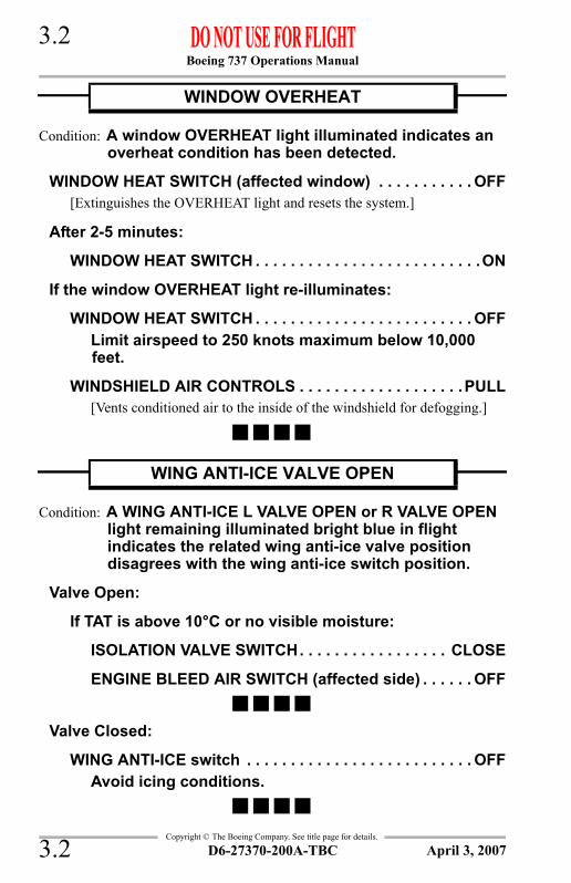
Boeing 737 Operations Manual 3.2
Copyright © The Boeing Company. See title page for details.
Condition: A window OVERHEAT light illuminated indicates an overheat condition has been detected.
WINDOW HEAT SWITCH (affected window) . . . . . . . . . . . OFF[Extinguishes the OVERHEAT light and resets the system.]
After 2-5 minutes:
WINDOW HEAT SWITCH . . . . . . . . . . . . . . . . . . . . . . . . . .ON
If the window OVERHEAT light re-illuminates:
WINDOW HEAT SWITCH . . . . . . . . . . . . . . . . . . . . . . . . . OFFLimit airspeed to 250 knots maximum below 10,000 feet.
WINDSHIELD AIR CONTROLS . . . . . . . . . . . . . . . . . . .PULL[Vents conditioned air to the inside of the windshield for defogging.]
Condition: A WING ANTI-ICE L VALVE OPEN or R VALVE OPEN light remaining illuminated bright blue in flight indicates the related wing anti-ice valve position disagrees with the wing anti-ice switch position.
Valve Open:
If TAT is above 10°C or no visible moisture:
ISOLATION VALVE SWITCH. . . . . . . . . . . . . . . . . CLOSE
ENGINE BLEED AIR SWITCH (affected side) . . . . . . OFF
Valve Closed:
WING ANTI-ICE switch . . . . . . . . . . . . . . . . . . . . . . . . . . OFFAvoid icing conditions.
WINDOW OVERHEAT
WING ANTI-ICE VALVE OPEN
D6-27370-200A-TBC3.2 April 3, 2007

Boeing 737 Operations Manual
Non-Normal Checklists Chapter NNCAutomatic Flight Section 4
Copyright © The Boeing Company. See title page for details.
Table of ContentsNNC.4 Non-Normal Checklists-Automatic FlightAUTOPILOT DISENGAGE . . . . . . . . . . . . . . . . . . . . . . . . . . . . . . 4.1
D6-27370-200A-TBC TOC.4.1April 1, 2005

Boeing 737 Operations Manual
Non-Normal Checklists -Automatic Flight
Copyright © The Boeing Company. See title page for details.
IntentionallyBlank
TOC.4.2 D6-27370-200A-TBC April 1, 2005

Boeing 737 Operations Manual 4.1
Copyright © The Boeing Company. See title page for details.
NNC.4 Non-Normal Checklists-Automatic Flight
Condition: The flashing red AUTO PILOT light illuminated indicates the autopilot has disengaged.
Fly the airplane manually or re-engage an autopilot.
AUTOPILOT DISENGAGE
D6-27370-200A-TBC 4.1April 1, 2005

Boeing 737 Operations Manual 4.2
Copyright © The Boeing Company. See title page for details.
IntentionallyBlank
D6-27370-200A-TBC4.2 April 7, 2000

Boeing 737 Operations Manual
Non-Normal Checklists Chapter NNCCommunications Section 5
Copyright © The Boeing Company. See title page for details.
Table of ContentsNNC.5 Non-Normal Checklists-CommunicationsRADIO TRANSMIT CONTINUOUS (STUCK
MICROPHONE SWITCH) . . . . . . . . . . . . . . . . . . . . . . . . . . . . . . 5.1
D6-27370-200A-TBC TOC.5.1April 1, 2005

Boeing 737 Operations Manual
Non-Normal Checklists -Communications
Copyright © The Boeing Company. See title page for details.
IntentionallyBlank
TOC.5.2 D6-27370-200A-TBC April 1, 2005

Boeing 737 Operations Manual 5.1
Copyright © The Boeing Company. See title page for details.
NNC.5 Non-Normal Checklists-Communications
Condition: A radio is continuously transmitting without crew input.
Transmitter select switches(all audio selector panels) . . . . . . . . . . . . . . .Flight interphone
[Deselects radios and stops radio transmissions.]
The microphone/interphone with the stuck switch continuously transmits on flight interphone.The associated audio selector panel should remain on flight interphone. All other audio selector panels may be used normally.
RADIO TRANSMIT CONTINUOUS (STUCK MICROPHONE SWITCH)
D6-27370-200A-TBC 5.1October 6, 2006

Boeing 737 Operations Manual 5.2
Copyright © The Boeing Company. See title page for details.
IntentionallyBlank
D6-27370-200A-TBC5.2 April 7, 2000

Boeing 737 Operations Manual
Non-Normal Checklists Chapter NNCElectrical Section 6
Copyright © The Boeing Company. See title page for details.
Table of ContentsNNC.6 Non-Normal Checklists-ElectricalBUS OFF . . . . . . . . . . . . . . . . . . . . . . . . . . . . . . . . . . . . . . . . . . . . . 6.1
CSD HIGH OIL TEMPERATURE . . . . . . . . . . . . . . . . . . . . . . . . . 6.1CSD LOW OIL PRESSURE . . . . . . . . . . . . . . . . . . . . . . . . . . . . . . 6.2LOSS OF BOTH ENGINE DRIVEN GENERATORS . . . . . . . . . . 6.4STANDBY POWER OFF . . . . . . . . . . . . . . . . . . . . . . . . . . . . . . . . 6.7TRANSFER BUS OFF . . . . . . . . . . . . . . . . . . . . . . . . . . . . . . . . . . . 6.7
D6-27370-200A-TBC TOC.6.1October 9, 2007

Boeing 737 Operations Manual
Non-Normal Checklists -Electrical
Copyright © The Boeing Company. See title page for details.
IntentionallyBlank
TOC.6.2 D6-27370-200A-TBC October 9, 2007

Boeing 737 Operations Manual 6.1
Copyright © The Boeing Company. See title page for details.
NNC.6 Non-Normal Checklists-Electrical
Condition: A BUS OFF light illuminated indicates the related generator bus is not powered.
Engine GENERATOR switch . . . . . . . . . . . . . . . . . . . . . . . . .ON
If the BUS OFF light remains illuminated:
If the APU is available:
APU . . . . . . . . . . . . . . . . . . . . . . . . . . . . . . . . . . . . START
APU GENERATOR switch . . . . . . . . . . . . . . . . . . . . . .ONNote: If the APU is not available, the galleys and one
system B hydraulic pump are not powered.
Condition: A CSD HIGH OIL TEMPERATURE light illuminated indicates oil temperature exceeds operating limits in the related generator drive.
Generator drive DISCONNECT switch . . . . . . . . . . . . . . . . . . . . . DISCONNECT
Hold in the DISCONNECT position momentarily.[Prevents generator drive damage.]
If the APU is available:
APU . . . . . . . . . . . . . . . . . . . . . . . . . . . . . . . . . . . . . . . START
APU GENERATOR switch . . . . . . . . . . . . . . . . . . . . . . . . .ONNote: If the APU is not available, the galleys and one system
B hydraulic pump are not powered.
BUS OFF
CSD HIGH OIL TEMPERATURE
D6-27370-200A-TBC 6.1October 9, 2007

Boeing 737 Operations Manual 6.2
Copyright © The Boeing Company. See title page for details.
Condition: A CSD LOW OIL PRESSURE light illuminated indicates oil pressure is below minimum operating limits in the related generator drive.
Generator drive DISCONNECT switch . . . . . . . . . . . . . . . . . . . . . .DISCONNECT
Hold in the DISCONNECT position momentarily.[Prevents generator drive damage.]
If the APU is available:
APU. . . . . . . . . . . . . . . . . . . . . . . . . . . . . . . . . . . . . . . .START
APU GENERATOR switch . . . . . . . . . . . . . . . . . . . . . . . . .ONNote: If the APU is not available, the galleys and one system
B hydraulic pump are not powered.
CSD LOW OIL PRESSURE
D6-27370-200A-TBC6.2 October 9, 2007

Boeing 737 Operations Manual 6.3
Copyright © The Boeing Company. See title page for details.
IntentionallyBlank
D6-27370-200A-TBC 6.3October 8, 2004

Boeing 737 Operations Manual 6.4
Copyright © The Boeing Company. See title page for details.
Condition: All TRANSFER BUS OFF, BUS OFF and GEN OFF BUS lights illuminated indicate the loss of both engine driven generators.
Note: At high altitude, thrust deterioration or engine flameout may occur.
GALLEY power switch. . . . . . . . . . . . . . . . . . . . . . . . . . . . . OFF
BUS TRANSFER switch. . . . . . . . . . . . . . . . . . . . . . . . . . . . OFF[Prevents high electrical loads during attempts to restore power.]
System B HYDRAULIC PUMPS switches . . . . . . . . . . . . . OFF[Prevents high electrical loads during attempts to restore power.]
Engine No. 2 GENERATOR switch . . . . . . . . . . . . . . . . . . . .ON
Engine No. 1 GENERATOR switch . . . . . . . . . . . . . . . . . . . .ON
If both BUS OFF lights are extinguished:
BUS TRANSFER switch . . . . . . . . . . . . . . . . . . . . . . . AUTO
System B HYDRAULIC PUMPS switches . . . . . . . . . . . . . . . . . . . . . . . . . . ON (one at a time)
[Prevents high peak electrical loads.]
GALLEY power switch . . . . . . . . . . . . . . . . . . . . As needed
Continued on next page
LOSS OF BOTH ENGINE DRIVEN GENERATORS
D6-27370-200A-TBC6.4 October 9, 2007

Boeing 737 Operations Manual 6.5
Copyright © The Boeing Company. See title page for details.
Continued from previous page
If one BUS OFF light is illuminated:
If the APU is available:Note: APU start attempts are not recommended
above 25,000 feet.
APU . . . . . . . . . . . . . . . . . . . . . . . . . . . . . . . . . . . . START
APU GENERATOR switch . . . . . . . . . . . . . . . . . . . . . .ON
If both BUS OFF lights are extinguished:
BUS TRANSFER switch. . . . . . . . . . . . . . . . . . . AUTO
System B HYDRAULIC PUMPS switches . . . . . . . . . . . . . . . . . . . . . ON (one at a time)
[Prevents high peak electrical loads.]
GALLEY power switch. . . . . . . . . . . . . . . . As needed
If one BUS OFF light is illuminated:
BUS TRANSFER switch. . . . . . . . . . . . . . . . . . . AUTO
One system B HYDRAULIC PUMPS switch . . . . . .ON
GALLEY power switch. . . . . . . . . . . . . . . . As needed
If the APU is not available:
BUS TRANSFER switch . . . . . . . . . . . . . . . . . . . . . AUTO[Restores power to the remaining bus.]
One system B HYDRAULIC PUMPS switch . . . . . . . .ON
GALLEY power switch . . . . . . . . . . . . . . . . . . As needed
Continued on next page
D6-27370-200A-TBC 6.5October 9, 2007

Boeing 737 Operations Manual 6.6
Copyright © The Boeing Company. See title page for details.
Continued from previous page
If both BUS OFF lights are illuminated:
If the APU is available:Note: APU start attempts are not recommended
above 25,000 feet.
APU . . . . . . . . . . . . . . . . . . . . . . . . . . . . . . . . . . . . .START[With both busses off, only one start attempt is recommended. Multiple start attempts reduce standby power capacity.]
APU GENERATOR switch . . . . . . . . . . . . . . . . . . . . . .ON
Note: Connect the APU to the No. 2 bus to power TR2 and TR3. If the APU cannot be connected to the No. 2 bus, connect it to the No. 1 bus.
If one BUS OFF lights is illuminated:
BUS TRANSFER switch . . . . . . . . . . . . . . . . . . AUTO[Restores power to the remaining transfer bus.]
One system B HYDRAULIC PUMPS switch . . . . . .ON
GALLEY power switch . . . . . . . . . . . . . . . As needed
If both BUS OFF lights are illuminated:
All exterior lights . . . . . . . . . . . . . . . . . . . . . . . . . . OFF[Conserves battery power.]
Avoid icing conditions.
Note: Flight in icing conditions may result in erroneous flight instrument indications.
Plan to land at the nearest suitable airport.
Note: A fully charged battery provides a minimum of 30 minutes of standby power.
Continued on next page
D6-27370-200A-TBC6.6 October 9, 2007

Boeing 737 Operations Manual 6.7
Copyright © The Boeing Company. See title page for details.
Continued from previous page
If both BUS OFF lights are illuminated: (continued)
If the APU is not available:
All exterior lights . . . . . . . . . . . . . . . . . . . . . . . . . . . . OFF[Conserves battery power.]
Avoid icing conditions.
Note: Flight in icing conditions may result in erroneous flight instrument indications.
Plan to land at the nearest suitable airport.
Note: A fully charged battery provides a minimum of 30 minutes of standby power.
Condition: The STANDBY PWR OFF light illuminated indicates the AC standby bus is not powered.
STANDBY POWER switch . . . . . . . . . . . . . . . . . . . . . . . . . . BAT[A fully charged battery provides a minimum of 30 minutes of standby power.]
If either generator bus is re-established:
STANDBY POWER switch . . . . . . . . . . . . . . . . . . . . . AUTO
Condition: A TRANSFER BUS OFF light illuminated indicates the related transfer bus is not powered.
BUS TRANSFER switch . . . . . . . . . . . . . . . . . OFF THEN AUTO
STANDBY POWER OFF
TRANSFER BUS OFF
D6-27370-200A-TBC 6.7October 9, 2007

Boeing 737 Operations Manual 6.8
Copyright © The Boeing Company. See title page for details.
IntentionallyBlank
D6-27370-200A-TBC6.8 October 9, 2007

Boeing 737 Operations Manual
Non-Normal Checklists Chapter NNCEngines, APU Section 7
Copyright © The Boeing Company. See title page for details.
Table of ContentsNNC.7 Non-Normal Checklists-Engines, APUABORTED ENGINE START . . . . . . . . . . . . . . . . . . . . . . . . . . . . 7.1
APU DET INOP . . . . . . . . . . . . . . . . . . . . . . . . . . . . . . . . . . . . . . . . 7.1APU FIRE . . . . . . . . . . . . . . . . . . . . . . . . . . . . . . . . . . . . . . . . . . . . 7.2APU HIGH OIL TEMPERATURE OR LOW OIL
PRESSURE . . . . . . . . . . . . . . . . . . . . . . . . . . . . . . . . . . . . . . . . . . 7.2APU OVERSPEED . . . . . . . . . . . . . . . . . . . . . . . . . . . . . . . . . . . . . 7.3ENGINE FAILURE/SHUTDOWN . . . . . . . . . . . . . . . . . . . . . . . . . 7.4ENGINE FIRE, SEVERE DAMAGE OR SEPARATION . . . . . 7.6ENGINE HIGH OIL TEMPERATURE . . . . . . . . . . . . . . . . . . . . . . 7.8ENGINE IN-FLIGHT START . . . . . . . . . . . . . . . . . . . . . . . . . . . . 7.10ENGINE LIMIT/SURGE/STALL . . . . . . . . . . . . . . . . . . . . . . . 7.12ENGINE LOW OIL PRESSURE . . . . . . . . . . . . . . . . . . . . . . . . . . 7.14ENGINE OIL FILTER BYPASS . . . . . . . . . . . . . . . . . . . . . . . . . . 7.16ENGINE OVERHEAT . . . . . . . . . . . . . . . . . . . . . . . . . . . . . . . . . 7.17ENGINE TAILPIPE FIRE . . . . . . . . . . . . . . . . . . . . . . . . . . . . . . . 7.18HIGH ENGINE VIBRATION . . . . . . . . . . . . . . . . . . . . . . . . . . . . 7.19NO STARTER CUTOUT/START VALVE OPEN . . . . . . . . . . . . . 7.22ONE ENGINE INOPERATIVE LANDING . . . . . . . . . . . . . . . . . 7.24REVERSER UNLOCKED (IN FLIGHT) . . . . . . . . . . . . . . . . . . . 7.26THRUST REVERSER ISOLATION VALVE . . . . . . . . . . . . . . . . 7.28VOLCANIC ASH . . . . . . . . . . . . . . . . . . . . . . . . . . . . . . . . . . . . . . 7.30
D6-27370-200A-TBC TOC.7.1April 9, 2008

Boeing 737 Operations Manual
Non-Normal Checklists -Engines, APU
Copyright © The Boeing Company. See title page for details.
IntentionallyBlank
TOC.7.2 D6-27370-200A-TBC April 9, 2008

Boeing 737 Operations Manual 7.1
Copyright © The Boeing Company. See title page for details.
NNC.7 Non-Normal Checklists-Engines, APU
Condition: During a ground start, an abort engine start condition occurs.
If the ENGINE START switch is in GRD:
Motor the engine for 20 seconds.
ENGINE START switch . . . . . . . . . . . . . . . . . . . . . . . . . . OFF
If the ENGINE START switch is in OFF:
After N2 decreases to 0%:
ENGINE START switch . . . . . . . . . . . . . . . . . . . . . . . GRD
Motor the engine for 20 seconds.
ENGINE START switch . . . . . . . . . . . . . . . . . . . . . . . . OFF
Condition: The APU DET INOP light illuminated indicates the APU fire detection loop has failed.
APU SWITCH . . . . . . . . . . . . . . . . . . . . . . . . . . . . . . . . . . . . OFF
CAUTION: Do not operate the APU. An APU fire would not be detected and the APU would continue to run.
ABORTED ENGINE START
Engine start lever . . . . . . . . . . . . . . . . . . . . . . . . . . . . . CUTOFF
APU DET INOP
D6-27370-200A-TBC 7.1April 1, 2005

Boeing 737 Operations Manual 7.2
Copyright © The Boeing Company. See title page for details.
Condition: Fire is detected in the APU.
If the APU fire switch remains illuminated:
Plan to land at the nearest suitable airport.
On the ground and no AC power is available:
STANDBY POWER switch . . . . . . . . . . . . . . . . . . . . . . . BAT
Condition: The APU HIGH OIL TEMPERATURE/LOW OIL PRESSURE light illuminated indicates an APU malfunction exists.
Note: The APU shuts down automatically.
APU SWITCH . . . . . . . . . . . . . . . . . . . . . . . . . . . . . . . . . . . . OFF
APU FIRE
APU fire switch . . . . . . . . . . . . . . . . . . . . . Pull, rotate and holdRotate to the stop and hold for 1 second.
APU switch . . . . . . . . . . . . . . . . . . . . . . . . . . . . . . . . . . . . . .OFF
APU HIGH OIL TEMPERATURE OR LOW OIL PRESSURE
D6-27370-200A-TBC7.2 October 7, 2005

Boeing 737 Operations Manual 7.3
Copyright © The Boeing Company. See title page for details.
Condition: The APU OVERSPEED light illuminated indicates one of the following:
• APU RPM limit has been exceeded resulting in an automatic shutdown
• the overspeed shutdown protection feature has failed a self-test during a normal APU shutdown
• an APU start has been manually aborted prior to the APU reaching normal operating speed.
APU SWITCH . . . . . . . . . . . . . . . . . . . . . . . . . . . . . . . . . . . . OFFNote: If the OVERSPEED light illuminated due to an RPM
limit being exceeded, the APU OVERSPEED RESET switch in the E/E compartment must be reset before another APU start can be attempted.
APU OVERSPEED
D6-27370-200A-TBC 7.3April 1, 2005

Boeing 737 Operations Manual 7.4
Copyright © The Boeing Company. See title page for details.
Condition: Loss of all thrust on an engine as indicated by the engine indicators, or abnormal engine indications.
Accomplish an engine shutdown only when flight conditions permit.Thrust lever . . . . . . . . . . . . . . . . . . . . . . . . . . . . . . . . . . . .Close
[Assists in recognition of affected engine.]
Conditions permitting, operate for two minutes at idle thrust.Engine start lever . . . . . . . . . . . . . . . . . . . . . . . . . . . . . CUTOFF
If the APU is available
APU. . . . . . . . . . . . . . . . . . . . . . . . . . . . . . . . . . . . . . . .START
APU GENERATOR switch . . . . . . . . . . . . . . . . . . . . . . . . .ON
If the APU is not available:
GALLEY power switch . . . . . . . . . . . . . . . . . . . . As neededNote: The galleys and one system B hydraulic pump are
not powered.
Fuel . . . . . . . . . . . . . . . . . . . . . . . . . . . . . . . . . . . . . . . . .Balance
Transponder mode selector(TCAS equipped airplanes) . . . . . . . . . . . . . . . . . . . . . . . . . . TA
[Prevents climb commands which can exceed single engine performance capability.]
If wing anti–ice is needed:
PACK switch (affected side) . . . . . . . . . . . . . . . . . . . . . . OFF
ISOLATION VALVE switch . . . . . . . . . . . . . . . . . . . . . AUTO
Plan to land at the nearest suitable airport.Do the ONE ENGINE INOPERATIVE LANDING checklist.
ENGINE FAILURE/SHUTDOWN
D6-27370-200A-TBC7.4 October 9, 2007

Boeing 737 Operations Manual 7.5
Copyright © The Boeing Company. See title page for details.
IntentionallyBlank
D6-27370-200A-TBC 7.5October 8, 2004

Boeing 737 Operations Manual 7.6
Copyright © The Boeing Company. See title page for details.
Condition: Fire is detected in the associated engine; severe damage which may be associated with airframe and/or abnormal engine indications has occurred; or the engine has separated.
Note: The galleys and one system B hydraulic pump are not powered.
If the engine fire warning switch or ENG OVERHEAT light remains illuminated:
Engine fire warning switch . . . . . . . . . . . . . . . Rotate L or RRotate to the stop and hold for one second.
If after 30 seconds the engine fire warning switch or ENG OVERHEAT light remains illuminated:
Engine fire warning switch . . . . . . . . . . . . . . . . . . . . . . . . . .Rotate to
the remaining bottleRotate to the opposite stop and hold for one second.
ISOLATION VALVE switch . . . . . . . . . . . . . . . . . . . . . . . CLOSE
APU BLEED air switch. . . . . . . . . . . . . . . . . . . . . . . . . . . . . OFF
Continued on next page
ENGINE FIRE, SEVERE DAMAGE OR SEPARATION
Thrust lever . . . . . . . . . . . . . . . . . . . . . . . . . . . . . . . . . . . . Close[Assists in recognition of affected engine.]
Engine start lever . . . . . . . . . . . . . . . . . . . . . . . . . . . . . CUTOFF
Engine fire warning switch . . . . . . . . . . . . . . . . . . . . . . . . . PullTo manually unlock the engine fire warning switch, press the override and pull.
D6-27370-200A-TBC7.6 April 9, 2008

Boeing 737 Operations Manual 7.7
Copyright © The Boeing Company. See title page for details.
Continued from previous page
If the APU is available:
APU . . . . . . . . . . . . . . . . . . . . . . . . . . . . . . . . . . . . . . . START
APU GENERATOR switch . . . . . . . . . . . . . . . . . . . . . . . . .ONNote: If the APU is not available, the galleys and one system
B hydraulic pump are not powered.
Fuel . . . . . . . . . . . . . . . . . . . . . . . . . . . . . . . . . . . . . . . . Balance
Transponder mode selector(TCAS equipped airplanes) . . . . . . . . . . . . . . . . . . . . . . . . . . TA
[Prevents climb commands which can exceed single engine performance capability.]
If wing anti–ice is required:
PACK switch (affected side) . . . . . . . . . . . . . . . . . . . . . . OFF
ISOLATION VALVE switch (after fire has been extinguished) . . . . . . . . . . . . . . . . . . . . . . . . . . . . . . . . AUTO
Plan to land at the nearest suitable airport.Accomplish the ONE ENGINE INOPERATIVE LANDING checklist when appropriate.
D6-27370-200A-TBC 7.7October 9, 2007

Boeing 737 Operations Manual 7.8
Copyright © The Boeing Company. See title page for details.
Condition: Engine oil temperature is in the yellow band, or at or above the red radial.
If temperature is in the yellow band:
FUEL HEAT . . . . . . . . . . . . . . . . . . . . . . . . . . . . . . . . . CheckIf fuel heat is on or has been used in the previous minute, monitor oil temperature decrease into green band after fuel heat is off.
If temperature rise occurred after a thrust reduction:
Thrust lever . . . . . . . . . . . . . . . . . . . . . . . . . . . . . Advance
If temperature rise did not occur after a thrust reduction:
Thrust lever (slowly) . . . . . . . . . . . . . . . . . . . . . . . . RetardRetard until engine oil temperature is within normal operating range or thrust lever is closed.
If temperature is in the yellow band for more than 15 minutes:
Thrust lever . . . . . . . . . . . . . . . . . . . . . . . . . . . . . . . .Close
Engine start lever . . . . . . . . . . . . . . . . . . . . . . . . CUTOFF
If the APU is available:
APU . . . . . . . . . . . . . . . . . . . . . . . . . . . . . . . . . . . . .START
APU GENERATOR switch . . . . . . . . . . . . . . . . . . . . . .ON
Note: if the APU is not available, the galleys and one system B hydraulic pump are not powered.
Transponder mode selector(TCAS equipped airplanes) . . . . . . . . . . . . . . . . . . . . . . . TA
[Prevents climb commands which can exceed single engine performance capability.]
Continued on next page
ENGINE HIGH OIL TEMPERATURE
D6-27370-200A-TBC7.8 October 9, 2007

Boeing 737 Operations Manual 7.9
Copyright © The Boeing Company. See title page for details.
Continued from previous page
If temperature is in the yellow band: (continued)
If wing anti–ice is needed:
PACK switch (affected side) . . . . . . . . . . . . . . . . . . . OFF
ISOLATION VALVE switch . . . . . . . . . . . . . . . . . . . AUTO
Plan to land at the nearest suitable airport.
Balance fuel as needed.
Do the ONE ENGINE INOPERATIVE LANDING checklist.
If temperature is at or above the red radial:
Thrust lever . . . . . . . . . . . . . . . . . . . . . . . . . . . . . . . . . Close
Engine start lever . . . . . . . . . . . . . . . . . . . . . . . . . . CUTOFF
If the APU is available:
APU . . . . . . . . . . . . . . . . . . . . . . . . . . . . . . . . . . . . START
APU GENERATOR switch . . . . . . . . . . . . . . . . . . . . . .ON
Note: if the APU is not available, the galleys and one system B hydraulic pump are not powered.
Transponder mode selector . . . . . . . . . . . . . . . . . . . . . . . TA
If wing anti–ice is needed:
PACK switch (affected side) . . . . . . . . . . . . . . . . . . . OFF
ISOLATION VALVE switch . . . . . . . . . . . . . . . . . . . AUTO
Plan to land at the nearest suitable airport.
Balance fuel as needed.
Do the ONE ENGINE INOPERATIVE LANDING checklist.
D6-27370-200A-TBC 7.9October 9, 2007

Boeing 737 Operations Manual 7.10
Copyright © The Boeing Company. See title page for details.
Condition: Engine start is needed after a shutdown with no fire or apparent damage.
Complete the ENGINE FAILURE/SHUTDOWN checklist before attempting an in flight engine start.In-flight start envelope. . . . . . . . . . . . . . . . . . . . . . . . . . . Check
If either N1 or N2 RPM disagrees with the air start envelope (within 3%), suspect possible internal engine damage. Do not restart.
Thrust lever . . . . . . . . . . . . . . . . . . . . . . . . . . . . . . . . . . . .Close
ENGINE START switch . . . . . . . . . . . . . . . . . . . . . . . . . . . . FLT
Engine start lever . . . . . . . . . . . . . . . . . . . . . . . . . . IDLE detentMonitor engine instruments.
If EGT does not increase in 30 seconds or another abort start condition as listed in normal procedures occurs:
Engine start lever . . . . . . . . . . . . . . . . . . . . . . . . . . CUTOFF
ENGINE START switch . . . . . . . . . . . . . . . . . . . . . . . . . . OFF
Engines may accelerate to idle very slowly, especially at high altitudes. Slow acceleration may be incorrectly interpreted as a hung start or an engine malfunction. If N2 is steadily increasing, and EGT remains within limits, the start is progressing normally.After engine start:
Engine GENERATOR switch . . . . . . . . . . . . . . . . . . . . . .ON
PACK switch . . . . . . . . . . . . . . . . . . . . . . . . . . . . . . . . . . .ON
ENGINE START switch . . . . . . . . . . . . . . . . . . . . As needed
APU. . . . . . . . . . . . . . . . . . . . . . . . . . . . . . . . . . . . As needed
Continued on next page
ENGINE IN-FLIGHT START
D6-27370-200A-TBC7.10 October 9, 2007

Boeing 737 Operations Manual 7.11
Copyright © The Boeing Company. See title page for details.
Continued from previous page
After engine start: (continued)
Transponder mode selector(TCAS equipped airplanes) . . . . . . . . . . . . . . . . . . . . TA/RA
PRESSURE ALTITUDE 1000 FT
N1%N2%
IASKNOTS 0 5 10 15 20 25 30 35
340
320
300
280
260
240
220
200
180
160
16241522142113191318121711151014 912 811
172516231622152014191317121611
1013 911
14
19
1827
2517231622152014181317121511131012
2028
2719
18251723162115191418131612141112
2130202819271825172316211519141713151213
24332231212920271825172316211419
26352533233122292026182417221520
26332431222920261824
INFLIGHT START ENVELOPE JT8D-ALLNOMINAL WINDMILLING RPM (TOL. ±3%)
1725
1827
2028
2130
2433
2534
2533
2431
NOTE: INFLIGHT ENGINE STARTS ABOVE 29,000 FEET ARE____ NOT ASSURED.
D6-27370-200A-TBC 7.11April 3, 2007

Boeing 737 Operations Manual 7.12
Copyright © The Boeing Company. See title page for details.
Condition: One or more of the following conditions:• Engine RPM or EGT indications are abnormal,
approaching or exceeding limits• No response to thrust lever movement• Abnormal engine noises.
If indications are abnormal or EGT continues to increase:
Engine start lever . . . . . . . . . . . . . . . . . . . . . . . . . . CUTOFF
If the APU is available:
APU . . . . . . . . . . . . . . . . . . . . . . . . . . . . . . . . . . . . .START
APU GENERATOR switch . . . . . . . . . . . . . . . . . . . . . .ONNote: If the APU is not available, the galleys and one
system B hydraulic pump are not powered.
Fuel . . . . . . . . . . . . . . . . . . . . . . . . . . . . . . . . . . . . . . .Balance
Transponder mode selector(TCAS equipped airplanes) . . . . . . . . . . . . . . . . . . . . . . . TA
[Prevents climb commands which can exceed single engine performance capability.]
If wing anti-ice is required:
PACK switch (affected side) . . . . . . . . . . . . . . . . . . . OFF
ISOLATION VALVE switch . . . . . . . . . . . . . . . . . . . AUTO
Plan to land at the nearest suitable airport.
Do the ONE ENGINE INOPERATIVE LANDING checklist.
Continued on next page
ENGINE LIMIT/SURGE/STALL
Thrust lever . . . . . . . . . . . . . . . . . . . . . . . . . . . . . . . . . . . .RetardRetard until indications remain within appropriate limits or the thrust lever is closed.
D6-27370-200A-TBC7.12 October 9, 2007

Boeing 737 Operations Manual 7.13
Copyright © The Boeing Company. See title page for details.
Continued from previous page
If indications are stabilized and EGT decreases:
Thrust lever . . . . . . . . . . . . . . . . . . . . . . . . . . . . . . . AdvanceAdvance slowly. Check that RPM and EGT follow thrust lever movement.Operate engine normally or at a reduced thrust setting which is surge and stall free.
D6-27370-200A-TBC 7.13April 3, 2007

Boeing 737 Operations Manual 7.14
Copyright © The Boeing Company. See title page for details.
Condition: Engine oil pressure is below 40 psi, or the amber LOW OIL PRESSURE light is illuminated.
If engine oil pressure is in the yellow band:
Thrust lever . . . . . . . . . . . . . . . . . . . . . . . . . . . . . . . . . RetardOperate the engine at reduced thrust.
If the LOW OIL PRESSURE light is illuminated and engine oil pressure is normal:
Operate the engine normally. The thrust reverser may fail to operate.
Continued on next page
ENGINE LOW OIL PRESSURE
D6-27370-200A-TBC7.14 April 3, 2007

Boeing 737 Operations Manual 7.15
Copyright © The Boeing Company. See title page for details.
Continued from previous page
If engine oil pressure is at or below the red radial:
Thrust lever . . . . . . . . . . . . . . . . . . . . . . . . . . . . . . . . . Close
Engine start lever . . . . . . . . . . . . . . . . . . . . . . . . . . CUTOFF
If the APU is available:
APU . . . . . . . . . . . . . . . . . . . . . . . . . . . . . . . . . . . . START
APU GENERATOR switch . . . . . . . . . . . . . . . . . . . . . .ON
Note: if the APU is not available, the galleys and one system B hydraulic pump are not powered.
Transponder mode selector(TCAS equipped airplanes) . . . . . . . . . . . . . . . . . . . . . . . TA
[Prevents climb commands which can exceed single engine performance capability.]
If wing anti–ice is needed:
PACK switch (affected side) . . . . . . . . . . . . . . . . . . . OFF
ISOLATION VALVE switch . . . . . . . . . . . . . . . . . . . AUTO
Plan to land at the nearest suitable airport.
Balance fuel as needed.
Do the ONE ENGINE INOPERATIVE LANDING checklist.
D6-27370-200A-TBC 7.15October 9, 2007

Boeing 737 Operations Manual 7.16
Copyright © The Boeing Company. See title page for details.
Condition: An engine OIL FILTER BYPASS light illuminated indicates an impending bypass of the main oil filter.
Thrust lever . . . . . . . . . . . . . . . . . . . . . . . . . . . . . . . . . . . RetardRetard slowly until the engine OIL FILTER BYPASS light is extinguished or the thrust lever is closed.
If the OIL FILTER BYPASS light extinguishes:
Operate the engine at reduced thrust to keep the light extinguished.
If the OIL FILTER BYPASS light stays illuminated:
Engine start lever . . . . . . . . . . . . . . . . . . . . . . . . . . CUTOFF
If the APU is available:
APU . . . . . . . . . . . . . . . . . . . . . . . . . . . . . . . . . . . . .START
APU GENERATOR switch . . . . . . . . . . . . . . . . . . . . . .ON
Note: if the APU is not available, the galleys and one system B hydraulic pump are not powered.
TRANSPONDER MODE selector(TCAS equipped airplanes) . . . . . . . . . . . . . . . . . . . . . . . TA
[Prevents climb commands which can exceed single engine performance capability.]
Plan to land at the nearest suitable airport.
Balance fuel as needed.
If wing anti–ice is needed:
PACK switch (affected side) . . . . . . . . . . . . . . . . . . . OFF
ISOLATION VALVE switch . . . . . . . . . . . . . . . . . . . AUTO
Do the ONE ENGINE INOPERATIVE LANDING checklist.
ENGINE OIL FILTER BYPASS
D6-27370-200A-TBC7.16 October 9, 2007

Boeing 737 Operations Manual 7.17
Copyright © The Boeing Company. See title page for details.
Condition: The ENG OVERHEAT light illuminated indicates an overheat is detected on the related engine.
If the ENG OVERHEAT light extinguishes:
Operate the engine at reduced thrust to keep the light extinguished.
ENGINE OVERHEAT
THRUST LEVER . . . . . . . . . . . . . . . . . . . . . . . . . . . . . . . CLOSE
If the ENG OVERHEAT light remains illuminated:
Accomplish the ENGINE FIRE, SEVERE DAMAGE OR SEPARATION checklist.
D6-27370-200A-TBC 7.17April 3, 2007

Boeing 737 Operations Manual 7.18
Copyright © The Boeing Company. See title page for details.
Condition: An engine tailpipe fire is reported on the ground with no engine fire warning.
Engine start lever (affected engine) . . . . . . . . . . . . . . CUTOFF
Advise the cabin.If bleed air is available:
PACK switches (both) . . . . . . . . . . . . . . . . . . . . . . . . . . . OFF[Allows maximum bleed air for engine motoring.]
ISOLATION VALVE switch . . . . . . . . . . . . . . . . . . . . . AUTO[Ensures bleed air is available for engine motoring.]
Engine BLEED air switches (both) . . . . . . . . . . . . . . . . .ON
If APU is on:
APU BLEED air switch . . . . . . . . . . . . . . . . . . . . . . . . .ON
If the affected ENGINE START switch is not in GRD:
Allow the affected N2 to decrease to zero.
ENGINE START switch (affected engine) . . . . . . . . GRD
Advise the tower.
If the engine is being motored:
Continue to motor until the tailpipe fire is extinguished.
ENGINE START switch (affected engine) . . . . . . . . . . . OFF
ENGINE TAILPIPE FIRE
D6-27370-200A-TBC7.18 April 3, 2007
Boeing 737 Operations Manual 7.19
Copyright © The Boeing Company. See title page for details.
Condition: An increase in engine vibration is accompanied by airframe vibrations.
If not in icing conditions:
Thrust lever . . . . . . . . . . . . . . . . . . . . . . . . . . . . . . . . .RetardRetard to reduce engine vibration or until the thrust lever is closed.
Note: If the vibration does not decrease when the thrust lever is retarded, check other engine indications. If other engine indications are normal, no further action is required.
Continued on next page
HIGH ENGINE VIBRATION
D6-27370-200A-TBC 7.19October 9, 2007

Boeing 737 Operations Manual 7.20
Copyright © The Boeing Company. See title page for details.
Continued from previous page
If in icing conditions:
If engine anti-ice is not on, accomplish the following on one engine at a time:
ENGINE START switch . . . . . . . . . . . . . . . . . . . . . . . . FLT
Thrust . . . . . . . . . . . . . . . . . . . . . . . . . . . . . . . Idle detent
ENGINE ANTI-ICE switch . . . . . . . . . . . . . . . . . . . . . . .ON
Thrust . . . . . . . . . . . . . . . . . . . . . . . . . . . . . . . . . . . AdjustMaintain 70% N1 while monitoring engine instruments, especially EGT, for abnormal indications.
If vibration decreases:
Resume normal operations.
If vibration does not decrease in one minute:
Consider shutting down the engine.
Continued on next page
D6-27370-200A-TBC7.20 October 9, 2007

Boeing 737 Operations Manual 7.21
Copyright © The Boeing Company. See title page for details.
Continued from previous page
If in icing conditions: (continued)
If engine anti-ice is on, accomplish the following on one engine at a time:
ENGINE START switch . . . . . . . . . . . . . . . . . . . . . . . . FLT
Thrust . . . . . . . . . . . . . . . . . . . . . . . . . . . . . . . . . . . AdjustMaintain 70% N1 while monitoring engine instruments, especially EGT, for abnormal indications.
If vibration decreases:
Resume normal operations.
If vibration does not decrease in one minute:
Consider shutting down the engine.
D6-27370-200A-TBC 7.21October 9, 2007

Boeing 737 Operations Manual 7.22
Copyright © The Boeing Company. See title page for details.
Condition: The engine starter does not cut out by 40% N2, or the START VALVE OPEN light illuminates during ground or flight operations.
ENGINE START SWITCH . . . . . . . . . . . . . . . . . . . . . . . . . . . OFF
If no starter cutout or if START VALVE OPEN light remains illuminated:
START LEVER . . . . . . . . . . . . . . . . . . . . . . . . . . . . . CUTOFF
ISOLATION VALVE SWITCH . . . . . . . . . . . . . . . . . . . CLOSE
ENGINE BLEED AIR SWITCH (affected engine) . . . . . . OFF
In flight:
Accomplish the ENGINE FAILURE/ SHUTDOWN checklist.
NO STARTER CUTOUT/START VALVE OPEN
D6-27370-200A-TBC7.22 October 9, 2007

Boeing 737 Operations Manual 7.23
Copyright © The Boeing Company. See title page for details.
IntentionallyBlank
D6-27370-200A-TBC 7.23April 9, 2008

Boeing 737 Operations Manual 7.24
Copyright © The Boeing Company. See title page for details.
Condition: Landing must be accomplished with one engine inoperative.
Plan a flaps 15 landing.Set VREF 15.Maintain VREF 15 + 5 knots minimum on final approach. Apply normal wind correction but do not go below VREF 15 + 5 knots to assure adequate speed for go-around.----------------------------DEFERRED ITEMS ------------------------------==> DESCENT
Pressurization . . . . . . . . . . . . . . CAB ALT ___, LAND ALT ___
Gravel protect (as installed) . . . . . . . . . . . . . . . . . . . . . . . . ___
Recall . . . . . . . . . . . . . . . . . . . . . . . . . . . . . . . . . . . . . . Checked
Anti-ice . . . . . . . . . . . . . . . . . . . . . . . . . . . . . . . . . . . . . . . . . ___Use engine anti–ice on the operative engine only.
If additional go–around thrust is desired, below 10,000 feet configure the pressurization system for a no engine bleed landing:
WING ANTI-ICE switch . . . . . . . . . . . . . . . . . . . . . . . . . . OFF
ISOLATION VALVE switch . . . . . . . . . . . . . . . . . . . . CLOSE
Engine No. 1 BLEED air switch . . . . . . . . . . . . . . . . . . . OFF
APU BLEED air switch . . . . . . . . . . . . . . . . . . . . . . . . . . .ONDo not open the APU bleed valve if the engine firewarning switch remains illuminated.
Left PACK switch . . . . . . . . . . . . . . . . . . . . . . . . . . . . . . . .ON
Engine No. 2 BLEED air switch . . . . . . . . . . . . . . . . . . . OFF
Autobrake . . . . . . . . . . . . . . . . . . . . . . . . . . . . . . . . . . . . . . . ___
GROUND PROXIMITY FLAP/GEARINHIBIT switch . . . . . . . . . . . . . . . . . . . . . FLAP/GEAR INHIBIT
Continued on next page
ONE ENGINE INOPERATIVE LANDING
D6-27370-200A-TBC7.24 April 9, 2008

Boeing 737 Operations Manual 7.25
Copyright © The Boeing Company. See title page for details.
Continued from previous page
Landing data . . . . . . . . . . . . . . . . . . . . VREF 15, Minimums___
Approach briefing . . . . . . . . . . . . . . . . . . . . . . . . . . Completed
Go-around procedure . . . . . . . . . . . . . . . . . . . . . . . . . . ReviewAccomplish normal go-around procedure except:• Use flaps 1.• Maintain VREF 15 + 5 knots to flap retraction altitude.• Limit bank angle to 15° when airspeed is less than VREF
15 + 15 knots or the minimum maneuver speed, whichever is lower.
• Accelerate to 190 knots prior to flap retraction.----------------------------DEFERRED ITEMS ------------------------------==> APPROACH
Altimeters . . . . . . . . . . . . . . . . . . . . . . . . . . . . . . . . . . . . . . . ___----------------------------DEFERRED ITEMS ------------------------------==> LANDING
ENGINE START switch - operating engine . . . . . . . LOW IGN
Speedbrake . . . . . . . . . . . . . . . . . . . . . . . . . . . . . . . . . . . ARMED
Landing gear. . . . . . . . . . . . . . . . . . . . . . . . . . . . . . . . . . .DOWN
Flaps . . . . . . . . . . . . . . . . . . . . . . . . . . . . . . . . . . 15, green light
D6-27370-200A-TBC 7.25April 9, 2008

Boeing 737 Operations Manual 7.26
Copyright © The Boeing Company. See title page for details.
Condition: The REVERSER UNLOCKED light illuminated indicates that either of the two reverser sleeves has mechanically unlocked or that the REVERSER UNLOCKED light is giving a false indication.
Note: A Reverser failure may preclude returning the engine to forward thrust. Thrust reversal above 250 knots may fail the actuating linkage preventing retraction.
Forward thrust lever (affected engine) . . . . . . . . . . . . . Check
CAUTION: Do not actuate the reverse thrust lever.
If the engine responds to forward thrust lever movement and no buffet or yaw exists:
Operate the engine normally.
Continued on next page
REVERSER UNLOCKED (IN FLIGHT)
D6-27370-200A-TBC7.26 October 9, 2007
Boeing 737 Operations Manual 7.27
Copyright © The Boeing Company. See title page for details.
Continued from previous page
If the engine does not respond to forward thrust lever movement or buffet or yaw exists:
Thrust lever . . . . . . . . . . . . . . . . . . . . . . . . . . . . . . . . . Close
Engine start lever . . . . . . . . . . . . . . . . . . . . . . . . . . CUTOFF
If the APU is available:
APU . . . . . . . . . . . . . . . . . . . . . . . . . . . . . . . . . . . . START
APU GENERATOR switch . . . . . . . . . . . . . . . . . . . . . .ON
Note: if the APU is not available, the galleys and one system B hydraulic pump are not powered.
Transponder mode selector(TCAS equipped airplanes) . . . . . . . . . . . . . . . . . . . . . . . TA
[Prevents climb commands which can exceed single engine performance capability.]
Plan to land at the nearest suitable airport.
Balance fuel as needed.
If wing anti–ice is needed:
PACK switch (affected side) . . . . . . . . . . . . . . . . . . . OFF
ISOLATION VALVE switch . . . . . . . . . . . . . . . . . . . AUTO
Do the ONE ENGINE INOPERATIVE LANDING checklist.
D6-27370-200A-TBC 7.27October 9, 2007

Boeing 737 Operations Manual 7.28
Copyright © The Boeing Company. See title page for details.
Condition: The ISOLATION VALVE light illuminated indicates a disagreement between the isolation valve position and electrical or hydraulic inputs to the valve.
On the ground:
Reverse thrust may not be available. This may be due to a malfunction in the reverser system.
In flight:
Protection against thrust reversal may have been lost. Actuation of the reverse thrust levers may give immediate reverse thrust.
WARNING:Do not actuate the reverse thrust levers in flight.
THRUST REVERSER ISOLATION VALVE
D6-27370-200A-TBC7.28 October 9, 2007

Boeing 737 Operations Manual 7.29
Copyright © The Boeing Company. See title page for details.
IntentionallyBlank
D6-27370-200A-TBC 7.29October 9, 2007

Boeing 737 Operations Manual 7.30
Copyright © The Boeing Company. See title page for details.
Condition: Static discharge around the windshield, bright glow in the engine inlets, smoke or dust on the flight deck or an acrid odor indicates the airplane is in volcanic ash.
Exit volcanic ash as quickly as possible. Consider a 180 degree turn.Oxygen masks and smoke goggles(if required) . . . . . . . . . . . . . . . . . . . . . . . . . . . . . . . . . . . . . . .ON
Crew communications(if needed). . . . . . . . . . . . . . . . . . . . . . . . . . . . . . . . . . Establish
Thrust levers . . . . . . . . . . . . . . . . . . . . . . . . . . . . . . . . . . .CloseConditions permitting, operate at idle thrust.[Reduces possible engine damage and/or flameout by decreasing EGT.]
ENGINE START switches . . . . . . . . . . . . . . . . . . . . . . . . . . FLT
PACK switches . . . . . . . . . . . . . . . . . . . . . . . . . . . . . . . . . . . .ON
WING ANTI–ICE switch . . . . . . . . . . . . . . . . . . . . . . . . . . . . .ON[Increases bleed air extraction to improve engine stall margin.]
ENGINE ANTI–ICE switches . . . . . . . . . . . . . . . . . . . . . . . . .ON[Increases bleed air extraction to improve engine stall margin.]
If the APU is available:
APU. . . . . . . . . . . . . . . . . . . . . . . . . . . . . . . . . . . . . . . .START[Provides backup electrical and pneumatic source, if needed.]
Continued on next page
VOLCANIC ASH
D6-27370-200A-TBC7.30 October 9, 2007

Boeing 737 Operations Manual 7.31
Copyright © The Boeing Company. See title page for details.
Continued from previous page
If engines have flamed out or stalled, or EGT increases beyond limit:
ENGINE START LEVERS . . . . . . . . . . . . . . . . . . . . CUTOFF
EGT decreasing:
ENGINE START LEVERS . . . . . . . . . . . . . .IDLE DETENT
If EGT reaches the red radial, repeat the above steps.
Engines may accelerate to idle very slowly, especially at high altitudes. Slow acceleration may be incorrectly interpreted as a hung start or an engine malfunction. If N2 is steadily increasing, and EGT remains within limits, the start is progressing normally.
Plan to land at the nearest suitable airport.
D6-27370-200A-TBC 7.31October 9, 2007

Boeing 737 Operations Manual 7.32
Copyright © The Boeing Company. See title page for details.
IntentionallyBlank
D6-27370-200A-TBC7.32 October 9, 2007
Boeing 737 Operations Manual
Non-Normal Checklists Chapter NNCFire Protection Section 8
Copyright © The Boeing Company. See title page for details.
Table of ContentsNNC.8 Non-Normal Checklists-Fire ProtectionAPU DET INOP . . . . . . . . . . . . . . . . . . . . . . . . . . . . . . . . . . . . . . . . 8.1
APU FIRE . . . . . . . . . . . . . . . . . . . . . . . . . . . . . . . . . . . . . . . . . . . . 8.1CARGO FIRE . . . . . . . . . . . . . . . . . . . . . . . . . . . . . . . . . . . . . . . . . . 8.2CARGO FIRE DETECTOR FAULT . . . . . . . . . . . . . . . . . . . . . . . . 8.2ENGINE FIRE, SEVERE DAMAGE OR SEPARATION . . . . . 8.4ENGINE OVERHEAT . . . . . . . . . . . . . . . . . . . . . . . . . . . . . . . . . . 8.6ENGINE TAILPIPE FIRE . . . . . . . . . . . . . . . . . . . . . . . . . . . . . . . . 8.7FUSELAGE FIRES CLASS B PASS/CARGO OR ALL
CARGO . . . . . . . . . . . . . . . . . . . . . . . . . . . . . . . . . . . . . . . . . . . . 8.8FUSELAGE FIRES CLASS E ALL CARGO . . . . . . . . . . . . . . 8.10SMOKE, FIRE OR FUMES . . . . . . . . . . . . . . . . . . . . . . . . . . . . . . 8.12SMOKE OR FUMES REMOVAL . . . . . . . . . . . . . . . . . . . . . . . . . 8.14WHEEL WELL FIRE . . . . . . . . . . . . . . . . . . . . . . . . . . . . . . . . . . . 8.16
D6-27370-200A-TBC TOC.8.1October 9, 2007

Boeing 737 Operations Manual
Non-Normal Checklists -Fire Protection
Copyright © The Boeing Company. See title page for details.
IntentionallyBlank
TOC.8.2 D6-27370-200A-TBC October 9, 2007
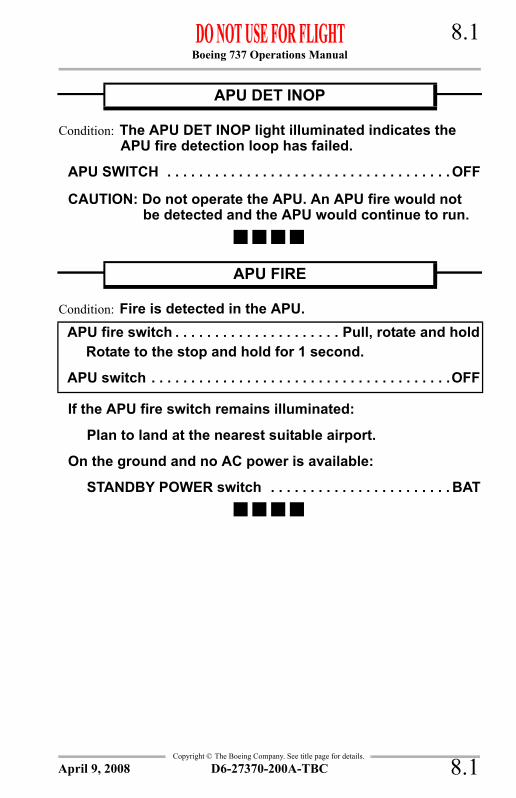
Boeing 737 Operations Manual 8.1
Copyright © The Boeing Company. See title page for details.
NNC.8 Non-Normal Checklists-Fire Protection
Condition: The APU DET INOP light illuminated indicates the APU fire detection loop has failed.
APU SWITCH . . . . . . . . . . . . . . . . . . . . . . . . . . . . . . . . . . . . OFF
CAUTION: Do not operate the APU. An APU fire would not be detected and the APU would continue to run.
Condition: Fire is detected in the APU.
If the APU fire switch remains illuminated:
Plan to land at the nearest suitable airport.
On the ground and no AC power is available:
STANDBY POWER switch . . . . . . . . . . . . . . . . . . . . . . . BAT
APU DET INOP
APU FIRE
APU fire switch . . . . . . . . . . . . . . . . . . . . . Pull, rotate and holdRotate to the stop and hold for 1 second.
APU switch . . . . . . . . . . . . . . . . . . . . . . . . . . . . . . . . . . . . . .OFF
D6-27370-200A-TBC 8.1April 9, 2008

Boeing 737 Operations Manual 8.2
Copyright © The Boeing Company. See title page for details.
Condition: Fire is detected in the related cargo compartment.
CARGO FIRE ARM SWITCH (FWD/AFT) . . . . . . . . . . . ARMED
CARGO FIRE DISCHARGE SWITCH. . . . . . . . . . . . . . . . PUSHPush and hold for 1 second.
Note: DISCH light may require up to 30 seconds to illuminate.
ONE PACK SWITCH . . . . . . . . . . . . . . . . . . . . . . . . . . . . . . . OFF
Plan to land at the nearest suitable airport.
WARNING:After landing, inform ground personnel not to open the cargo door until all passengers and crew have exited the airplane and fire fighting equipment is nearby.
Condition: The DETECTOR FAULT light illuminated indicates both loops in one or both cargo compartments have failed.
The fire detection system in one or both cargo compartments is inoperative.
CARGO FIRE
CARGO FIRE DETECTOR FAULT
D6-27370-200A-TBC8.2 October 9, 2007

Boeing 737 Operations Manual 8.3
Copyright © The Boeing Company. See title page for details.
IntentionallyBlank
D6-27370-200A-TBC 8.3October 9, 2007

Boeing 737 Operations Manual 8.4
Copyright © The Boeing Company. See title page for details.
Condition: Fire is detected in the associated engine; severe damage which may be associated with airframe and/or abnormal engine indications has occurred; or the engine has separated.
Note: The galleys and one system B hydraulic pump are not powered.
If the engine fire warning switch or ENG OVERHEAT light remains illuminated:
Engine fire warning switch . . . . . . . . . . . . . . . Rotate L or RRotate to the stop and hold for one second.
If after 30 seconds the engine fire warning switch or ENG OVERHEAT light remains illuminated:
Engine fire warning switch . . . . . . . . . . . . . . . . . . . . . . . . . .Rotate to
the remaining bottleRotate to the opposite stop and hold for one second.
ISOLATION VALVE switch . . . . . . . . . . . . . . . . . . . . . . . CLOSE
APU BLEED AIR switch . . . . . . . . . . . . . . . . . . . . . . . . . . . . OFF
Continued on next page
ENGINE FIRE, SEVERE DAMAGE OR SEPARATION
Thrust lever . . . . . . . . . . . . . . . . . . . . . . . . . . . . . . . . . . . . Close[Assists in recognition of affected engine.]
Engine start lever . . . . . . . . . . . . . . . . . . . . . . . . . . . . . CUTOFF
Engine fire warning switch . . . . . . . . . . . . . . . . . . . . . . . . . PullTo manually unlock the engine fire warning switch, press the override and pull.
D6-27370-200A-TBC8.4 April 9, 2008

Boeing 737 Operations Manual 8.5
Copyright © The Boeing Company. See title page for details.
Continued from previous page
If the APU is available:
APU . . . . . . . . . . . . . . . . . . . . . . . . . . . . . . . . . . . . . . . START
APU GENERATOR switch . . . . . . . . . . . . . . . . . . . . . . . . .ONNote: If the APU is not available, the galleys and one system
B hydraulic pump are not powered.
Fuel . . . . . . . . . . . . . . . . . . . . . . . . . . . . . . . . . . . . . . . . Balance
Transponder mode selector(TCAS equipped airplanes) . . . . . . . . . . . . . . . . . . . . . . . . . . TA
[Prevents climb commands which can exceed single engine performance capability.]
If wing anti–ice is required:
PACK switch (affected side) . . . . . . . . . . . . . . . . . . . . . . OFF
ISOLATION VALVE switch (after fire has been extinguished) . . . . . . . . . . . . . . . . . . . . . . . . . . . . . . . . AUTO
Plan to land at the nearest suitable airport.Accomplish the ONE ENGINE INOPERATIVE LANDING checklist when appropriate.
D6-27370-200A-TBC 8.5October 9, 2007

Boeing 737 Operations Manual 8.6
Copyright © The Boeing Company. See title page for details.
Condition: The ENG OVERHEAT light illuminated indicates an overheat is detected on the related engine.
If the ENG OVERHEAT light extinguishes:
Operate the engine at reduced thrust to keep the light extinguished.
ENGINE OVERHEAT
THRUST LEVER . . . . . . . . . . . . . . . . . . . . . . . . . . . . . . . CLOSE
If the ENG OVERHEAT light remains illuminated:
Accomplish the ENGINE FIRE, SEVERE DAMAGE OR SEPARATION checklist.
D6-27370-200A-TBC8.6 October 9, 2007

Boeing 737 Operations Manual 8.7
Copyright © The Boeing Company. See title page for details.
Condition: An engine tailpipe fire is reported on the ground with no engine fire warning.
Engine start lever (Affected engine) . . . . . . . . . . . . . . CUTOFF
Advise the cabin.If bleed air is available:
PACK switches (Both) . . . . . . . . . . . . . . . . . . . . . . . . . . . OFF[Allows maximum bleed air for engine motoring.]
ISOLATION VALVE switch . . . . . . . . . . . . . . . . . . . . . AUTO[Ensures bleed air is available for engine motoring.]
Engine BLEED air switches (Both) . . . . . . . . . . . . . . . . .ON
If APU is on:
APU BLEED air switch . . . . . . . . . . . . . . . . . . . . . . . . .ON
If the affected ENGINE START switch is not in GRD:
Allow the affected N2 to decrease to zero.
ENGINE START switch (Affected engine) . . . . . . . . GRD
Advise the tower.
If the engine is being motored:
Continue to motor until the tailpipe fire is extinguished.
ENGINE START SWITCH (Affected engine) . . . . . . . . . OFF
ENGINE TAILPIPE FIRE
D6-27370-200A-TBC 8.7October 9, 2007

Boeing 737 Operations Manual 8.8
Copyright © The Boeing Company. See title page for details.
Condition: Fire is detected in the cargo compartment.
If the airplane is in the all cargo configuration:
At the captain’s discretion, accomplish the FUSELAGE FIRES CLASS E ALL CARGO Non-Normal checklist.
ENGINE No.1 THRUST . . . . . . . . . . . . . . . . . MINIMUM 1.2 EPR[Provides heat and maximum ventilation to the flight deck.]
If the airplane is pressurized:
SMOKE CLEARANCE SWITCH . . . . . . . . . . . . . P/C PRESSIf the Equipment Cooling light illuminates, turn off radios, avionics equipment, galleys and lights that are not required.[Smoke detection and equipment cooling are inoperative.]
ALTITUDE . . . . . . . . . . . . . . . . . . . . . . . . . .20,000–25,000 FTIf descent is required, maintain 1.2 EPR minimum.
If the airplane is unpressurized:
SMOKE CLEARANCESWITCH . . . . . . . . . . . . . . . . . . . . . .CARGO, P/C UNPRESS
Continued on next page
FUSELAGE FIRES CLASS B PASS/CARGO OR ALL CARGO
OXYGEN MASKS AND REGULATORS . . . . . . . . . . . ON, 100%[Prevents inhalation of smoke or fumes.]
SMOKE GOGGLES (If required) . . . . . . . . . . . . . . . . . . . . . .ONIf smoke affects vision, use the EMERGENCY position on the oxygen regulator to clear the goggles of smoke.
CABIN DOOR . . . . . . . . . . . . . . . . . . . . . . . . . . . . . . . . . CLOSE[Prevents smoke contamination of/from other compartments.]
CREW COMMUNICATIONS . . . . . . . . . . . . . . . . . . ESTABLISH
D6-27370-200A-TBC8.8 October 9, 2007

Boeing 737 Operations Manual 8.9
Copyright © The Boeing Company. See title page for details.
Continued from previous page
If the airplane is pressurized or unpressurized:
FLIGHT DECK AIR CONDITIONINGOUTLETS . . . . . . . . . . . . . . . . . . . . . . . . . . . . . . . . . . . OPEN
SMOKE MASK & PORTABLEOXYGEN BOTTLE . . . . . . . . . . . . . . . . . . . . . . . . . . . . . . .ON
MAIN CABIN CARGOCOMPARTMENT . . . . . . . . . . . . . . . . . . . . . . . . . . . . ENTER
CABIN DOOR . . . . . . . . . . . . . . . . . . . . . . . . . . . . . . . CLOSE
DRY CHEMICAL FIRE EXTINGUISHERAND NOZZLE EXTENSION . . . . . . . . . . . . . . . . . . . .OBTAIN
If dry chemical fire extinguisher is used, attach nozzle extension to enable a high concentration of chemical application to remote areas of the cargo compartment.
FIRE/SMOKE SOURCE(if not enclosed) . . . . . . . . . . . . . . . . . . . . . . . EXTINGUISH
Do not open a fully enclosed container. Using wet materials, block any accessible openings in the container. Do not waste chemical on fire or smoke source that is inaccessible.
Plan to land at the nearest suitable airport.
If fire/smoke source is extinguished and no structural damage has occurred:
SMOKE CLEARANCE SWITCH . . . . . . . . . . . . . . NORMAL
SMOKE/FUMES REMOVAL CHECKLIST(if required) . . . . . . . . . . . . . . . . . . . . . . . . . . . . COMPLETE
Accomplish this checklist if normal air conditioning configuration will not evacuate the smoke.
D6-27370-200A-TBC 8.9October 9, 2007

Boeing 737 Operations Manual 8.10
Copyright © The Boeing Company. See title page for details.
Condition: Fire is detected in the cargo compartment.
If an immediate landing can be made:
PRESSURIZATION MODESELECTOR. . . . . . . . . . . . . . . . . . . . . . . . . . . . . . . . . . .STBY
CABIN ALTITUDE SELECTOR(maximum 10,000 feet) . . . . . . . . . . . . . . . . . . . . INCREASE
CABIN RATE SELECTOR . . . . . . . . . . . . . .MAXIMUM INCRSelect cabin rate of climb to approximately 2,000 fpm to further increase ventilation rate.
L & R PACK . . . . . . . . . . . . . . . . . . . . . . . . . . . . .VERIFY ON
ENGINE No. 1 & No. 2BLEEDS . . . . . . . . . . . . . . . . . . . . . . . . . . . . . . . .VERIFY ON
ENGINE THRUST . . . . . . . . . . . . . . . . . . . MINIMUM 1.2 EPR
FLIGHT DECK AIR CONDITIONING &GASPER OUTLETS . . . . . . . . . . . . . . . . . . . . . . . . . . . OPEN
CAUTION: Do not open any flight deck window. Keep the cabin door closed.
Continued on next page
FUSELAGE FIRES CLASS E ALL CARGO
OXYGEN MASKS AND REGULATORS . . . . . . . . . . . ON, 100%[Prevents inhalation of smoke or fumes.]
SMOKE GOGGLES (If required) . . . . . . . . . . . . . . . . . . . . . .ONIf smoke affects vision, use the EMERGENCY position on the oxygen regulator to clear the goggles of smoke.
CABIN DOOR . . . . . . . . . . . . . . . . . . . . . . . . . . . . . . . . . CLOSE[Prevents smoke contamination of/from other compartments.]
CREW COMMUNICATIONS . . . . . . . . . . . . . . . . . . ESTABLISH
D6-27370-200A-TBC8.10 October 9, 2007

Boeing 737 Operations Manual 8.11
Copyright © The Boeing Company. See title page for details.
Continued from previous page
If an immediate landing cannot be made:
ALTITUDE . . . . . . . . . . . . . . . . . . . . . . . . . .20,000–25,000 FTMaintain altitude as long as practical.
WEATHER RADAR MODE SELECTOR(before 15,000 feet cabin altitude) . . . . . . . . . . . . . . . . . OFF
[Prevents damage to radar wave guide when unpressurized.]
SMOKE CLEARANCESWITCH . . . . . . . . . . . . . . . . . . . . . CARGO, P/C UNPRESS
ENGINE No. 1 THRUST . . . . . . . . . . . . . . MINIMUM 1.2 EPR
FLIGHT DECK AIR CONDITIONINGOUTLETS . . . . . . . . . . . . . . . . . . . . . . . . . . . . . . . . . . . OPEN
CAUTION: Do not open any flight deck window. Keep the cabin door closed.
Note: Do not pressurize unless fire is out and no structural damage has occurred.
Plan to land at the nearest suitable airport.
D6-27370-200A-TBC 8.11October 9, 2007

Boeing 737 Operations Manual 8.12
Copyright © The Boeing Company. See title page for details.
Condition: Smoke, fire or fumes is identified.
Diversion may be needed.
Oxygen masks (as needed) . . . . . . . . . . . . . . . . . . . . ON, 100%
Smoke goggles (as needed) . . . . . . . . . . . . . . . . . . . . . . . . .ONIf smoke/fumes affect vision, use the EMERGENCY position on the oxygen regulator to clear the goggles.
Crew and Cabin communications . . . . . . . . . . . . . . Establish
BUS TRANSFER switch. . . . . . . . . . . . . . . . . . . . . . . . . . . . OFF
GALLEY POWER switch . . . . . . . . . . . . . . . . . . . . . . . . . . . OFF
GASPER FAN SWITCH . . . . . . . . . . . . . . . . . . . . . . . . . . . . OFF
APU BLEED AIR switch . . . . . . . . . . . . . . . . . . . . . . . . . . . . OFF
Anytime the smoke or fumes becomes the greatest threat, do the SMOKE OR FUMES REMOVAL checklist.If the source of the smoke, fire or fumes is both obvious and can be extinguished quickly:
Source . . . . . . . . . . . . . . . . . . . . . . . .Isolate and extinguish
If possible, remove power from the affected equipment by switch or circuit breaker in the flight deck or cabin.
If both of the following are true.• The source is visually confirmed to be
extinguished, and• The smoke and fumes are decreasingContinue the flight at the Captain’s discretion.Restore unpowered items at the Captain’s discretion.Do the SMOKE OR FUMES REMOVAL checklist if needed.
Continued on next page
SMOKE, FIRE OR FUMES
D6-27370-200A-TBC8.12 October 9, 2007

Boeing 737 Operations Manual 8.13
Copyright © The Boeing Company. See title page for details.
Continued from previous page
EQUIP COOLING switch . . . . . . . . . . . . . . . . . . . .ALTERNATE
Instruct flight attendants to:• turn on cabin reading lights• turn on galley attendants work lights• turn off cabin fluorescent light switches.
Initiate a diversion to the nearest suitable airport while continuing the checklist.Consider an immediate landing if the smoke, fire or fumes situation becomes uncontrollable.Do not delay landing in an attempt to complete all of the following steps.ISOLATION VALVE switch . . . . . . . . . . . . . . . . . . . . . . . CLOSE
R PACK switch . . . . . . . . . . . . . . . . . . . . . . . . . . . . . . . . . . . OFF
Wait 2 minutes unless the smoke or fumes are increasing.[Allows time for the smoke or fumes to clear.]
If the smoke or fumes continue or are increasing:
R PACK switch . . . . . . . . . . . . . . . . . . . . . . . . . . . . . . . . . .ON
L PACK switch . . . . . . . . . . . . . . . . . . . . . . . . . . . . . . . . . OFF
Wait 2 minutes unless the smoke or fumes are increasing.
[Allows time for the smoke or fumes to clear.]
If the smoke or fumes continue or are increasing:
L PACK switch . . . . . . . . . . . . . . . . . . . . . . . . . . . . . . .ON
Consider an immediate landing.
Do the SMOKE OR FUMES REMOVAL checklist if needed.
D6-27370-200A-TBC 8.13October 9, 2007

Boeing 737 Operations Manual 8.14
Copyright © The Boeing Company. See title page for details.
Condition: Smoke or fumes removal is needed.
Do this checklist only when directed by the SMOKE, FIRE OR FUMES checklist.Do not delay landing in an attempt to complete the following steps.Flight deck door . . . . . . . . . . . . . . . . . . . . . . . . . . . . . . . . .Close
[Prevents the smoke or fumes from penetrating onto the flight deck.]
If pack(s) are ON:
Note: Do not turn on any PACK switch that was turned off by the SMOKE, FIRE OR FUMES checklist.
L and R PACK switches . . . . . . . . . . . . . . . . . . . . Verify ON
Pressurization mode selector . . . . . . . . . . . . . . . . . . .STBY
CAB ALT indicator (maximum 10,000 feet) . . . . . . . . . . . . . . . . . . . . . . Increase
[Increases the ventilation rate.]
Note: The intermittent cabin altitude/configuration warning horn will sound and the CABIN ALTITUDE light (as installed) will illuminate at a cabin altitude of approximately 10,000 feet.
CABIN RATE selector . . . . . . . . . . . . . . . . . Maximum INCR[Further increases the ventilation rate.]
Engine No. 1 and No. 2BLEED air switches . . . . . . . . . . . . . . . . . . . . . . . Verify ON
Engine thrust . . . . . . . . . . . . . . . . . . . . . . Minimum 1.2 EPR[Provides maximum cabin ventilation.]
Continued on next page
SMOKE OR FUMES REMOVAL
D6-27370-200A-TBC8.14 October 9, 2007

Boeing 737 Operations Manual 8.15
Copyright © The Boeing Company. See title page for details.
Continued from previous page
If pack(s) are ON: (continued)
Flight deck air conditioning and gasper outlets . . . . . . . . . . . . . . . . . . . . . . . . . . . . . . . . Open
CAUTION: Do not open any flight deck window. Keep the flight deck door closed.
If the smoke or fumes are uncontrollable:
Airplane altitude . . . . . . . . . . . . . . . Lowest safe altitude or 10,000 feet,
whichever is higher
At 14,000 feet or below:
Pressurization mode selector . . . . . . . . . . . . MAN AC
Outflow VALVE switch . . . . . . . . . . . . . . . . . . . . OPENPosition the outflow valve to full open. This causes the cabin airflow to carry smoke or fumes aft.
Return to the SMOKE, FIRE OR FUMES checklist and do the remaining steps.
If the packs are off and the smoke or fumes source is confirmed to be on the flight deck:
CAUTION: Window should not be opened unless the source is confirmed to be on the flight deck.
Normal holding airspeed . . . . . . . . . . . . . . . . . . . Establish[High airspeed may prevent opening the window.]
First officer’s sliding window . . . . . . . . . . . . . . . . . . . . Open
Return to the SMOKE, FIRE OR FUMES checklist and do the remaining steps.
D6-27370-200A-TBC 8.15October 9, 2007

Boeing 737 Operations Manual 8.16
Copyright © The Boeing Company. See title page for details.
Condition: A fire is detected in the main wheel well.
Observe gear EXTEND limit speed (270K/.82M.)
LANDING GEAR LEVER . . . . . . . . . . . . . . . . . . . . . . . . .DOWNNote: If the airplane is equipped with a nose wheel gravel
deflector system, extend the main landing gear manually with the landing gear lever in the OFF position to avoid extending the nose gear at high speed. (Nose gear extension speed is 180 knots.)
If the landing gear must be retracted for airplane performance, leave the landing gear extended for 20 minutes after the WHEEL WELL fire warning light has extinguished.
LANDING GEAR LEVER (if required)(235 Kts maximum) . . . . . . . . . . . . . . . . . . . . . . . . UP & OFF
Plan to land at the nearest suitable airport.
WHEEL WELL FIRE
D6-27370-200A-TBC8.16 April 3, 2007

Boeing 737 Operations Manual
Non-Normal Checklists Chapter NNCFlight Controls Section 9
Copyright © The Boeing Company. See title page for details.
Table of ContentsNNC.9 Non-Normal Checklists-Flight ControlsALL FLAPS UP LANDING . . . . . . . . . . . . . . . . . . . . . . . . . . . . . . 9.1
FEEL DIFFERENTIAL PRESSURE . . . . . . . . . . . . . . . . . . . . . . . . 9.2FLIGHT CONTROL LOW PRESSURE . . . . . . . . . . . . . . . . . . . . . 9.2JAMMED OR RESTRICTED FLIGHT CONTROLS . . . . . . . . . . 9.3LEADING EDGE FLAPS TRANSIT . . . . . . . . . . . . . . . . . . . . . . . 9.6MACH TRIM FAIL . . . . . . . . . . . . . . . . . . . . . . . . . . . . . . . . . . . . . 9.9RUNAWAY STABILIZER . . . . . . . . . . . . . . . . . . . . . . . . . . . . . . 9.10SPEED BRAKE DO NOT ARM . . . . . . . . . . . . . . . . . . . . . . . . . . 9.10STABILIZER OUT OF TRIM . . . . . . . . . . . . . . . . . . . . . . . . . . . . 9.11STABILIZER TRIM INOPERATIVE . . . . . . . . . . . . . . . . . . . . . . 9.12STANDBY RUDDER ON . . . . . . . . . . . . . . . . . . . . . . . . . . . . . . . 9.14TRAILING EDGE FLAP ASYMMETRY . . . . . . . . . . . . . . . . . . . 9.16TRAILING EDGE FLAP DISAGREE . . . . . . . . . . . . . . . . . . . . . 9.18TRAILING EDGE FLAPS UP LANDING . . . . . . . . . . . . . . . . . . 9.22UNCOMMANDED RUDDER/YAW OR ROLL . . . . . . . . . . . . 9.24YAW DAMPER . . . . . . . . . . . . . . . . . . . . . . . . . . . . . . . . . . . . . . . 9.29
D6-27370-200A-TBC TOC.9.1October 9, 2007

Boeing 737 Operations Manual
Non-Normal Checklists -Flight Controls
Copyright © The Boeing Company. See title page for details.
IntentionallyBlank
TOC.9.2 D6-27370-200A-TBC October 9, 2007

Boeing 737 Operations Manual 9.1
Copyright © The Boeing Company. See title page for details.
NNC.9 Non-Normal Checklists-Flight Controls
Condition: Leading edge devices and trailing edge flaps cannot be extended.
Burn off fuel to reduce touchdown speed.Set VREF 40 + 55 knots.
[If tire placard speed is exceeded, tire failure may occur.]
Check the appropriate Non-Normal Configuration Landing Distance table in the ADVISORY INFORMATION section of the Performance-Inflight chapter.Maintain 210 knots until on final.On gravel deflector equipped airplanes, slow to 180 knots before lowering the landing gear.Limit bank angle to 15° when airspeed is less than 210 knots.----------------------------DEFERRED ITEMS ------------------------------==> DESCENT
Pressurization . . . . . . . . . . . . . .CAB ALT ___, LAND ALT ___
Gravel protect (as installed) . . . . . . . . . . . . . . . . . . . . . . . . ___
Recall. . . . . . . . . . . . . . . . . . . . . . . . . . . . . . . . . . . . . . . Checked
Autobrake . . . . . . . . . . . . . . . . . . . . . . . . . . . . . . . . . . . . . . . ___
GROUND PROXIMITY FLAP/GEARINHIBIT switch . . . . . . . . . . . . . . . . . . . . . FLAP/GEAR INHIBIT
Landing data . . . . . . . . . . . VREF 40 + 55 knots, Minimums___
Approach briefing . . . . . . . . . . . . . . . . . . . . . . . . . . Completed
Go-around procedure . . . . . . . . . . . . . . . . . . . . . . . . . . ReviewAccomplish normal go-around procedure except:• Limit bank angle to 15° when airspeed is less than 210
knots.• Accelerate to 210 knots.
Continued on next page
ALL FLAPS UP LANDING
D6-27370-200A-TBC 9.1October 9, 2007

Boeing 737 Operations Manual 9.2
Copyright © The Boeing Company. See title page for details.
Continued from previous page----------------------------DEFERRED ITEMS ------------------------------==> APPROACH
Altimeters . . . . . . . . . . . . . . . . . . . . . . . . . . . . . . . . . . . . . . . ___----------------------------DEFERRED ITEMS ------------------------------==> LANDING
ENGINE START switches . . . . . . . . . . . . . . . . . . . . . .LOW IGN
Speedbrake . . . . . . . . . . . . . . . . . . . . . . . . . . . . . . . . . . . ARMED
Landing gear . . . . . . . . . . . . . . . . . . . . . . . . . . . . . . . . . .DOWN
Flaps . . . . . . . . . . . . . . . . . . . . . . . . . . . . . . . . . . . . .UP, no light
FASTEN BELTS switch . . . . . . . . . . . . . . . . . . . . . . . . . . . . .ON
Condition: The FEEL DIFF PRESS light illuminated indicates significant differential pressure in the elevator feel computer.
No crew action required in flight.
Condition: A FLT CONTROL LOW PRESSURE light illuminated indicates the related hydraulic system pressure to ailerons, elevators and rudder is low or the rudder pressure reducer has failed in the low pressure mode.
FLIGHT CONTROL SWITCH . . . . . . . . . . . . . . . . . . STBY RUD
FEEL DIFFERENTIAL PRESSURE
FLIGHT CONTROL LOW PRESSURE
D6-27370-200A-TBC9.2 April 3, 2007

Boeing 737 Operations Manual 9.3
Copyright © The Boeing Company. See title page for details.
Condition: Movement of the elevator, aileron/spoiler or rudder is restricted.
Autopilot (if engaged) . . . . . . . . . . . . . . . . . . . . . . . Disengage
Verify thrust is symmetrical.If rudder is jammed or restricted and STBY RUD ON light is not installed on the overhead Flight Control panel or is placarded INOP:
Accomplish the UNCOMMANDED RUDDER/YAW OR ROLL Non-Normal checklist.
Jammed or Restricted System . . . . . . . . . . . . . . . . OverpowerUse maximum force, including a combined effort of both pilots, if required. A maximum two-pilot effort on the controls will not cause a cable or system failure.
Do not turn off any flight control switches.
If controls are normal:
Accomplish the normal DESCENT, APPROACH and LANDING checklists.
Continued on next page
JAMMED OR RESTRICTED FLIGHT CONTROLS
D6-27370-200A-TBC 9.3April 1, 2005

Boeing 737 Operations Manual 9.4
Copyright © The Boeing Company. See title page for details.
Continued from previous page
If controls are not normal:
Use stabilizer or rudder trim to offload control forces.Note: If electric or manual stabilizer trim is desired, the
STAB BRAKE RELEASE knob must be pulled.
Do not make abrupt thrust changes. Extend or retract the speed brakes slowly and smoothly.
Limit bank angle to 15°.
Plan to land the nearest suitable airport.
Plan a flaps 15 landing.
Set VREF 15.------------------------DEFERRED ITEMS ------------------------------==> DESCENT
Pressurization . . . . . . . . . . . . CAB ALT ___, LAND ALT ___
Gravel protect (as installed) . . . . . . . . . . . . . . . . . . . . . . ___
Recall . . . . . . . . . . . . . . . . . . . . . . . . . . . . . . . . . . . . Checked
Autobrake. . . . . . . . . . . . . . . . . . . . . . . . . . . . . . . . . . . . . ___
GROUND PROXIMITY FLAP/GEARINHIBIT switch . . . . . . . . . . . . . . . . . . . FLAP/GEAR INHIBIT
Landing Data . . . . . . . . . . . . . . . . . VREF 15, Minimums___
Approach briefing . . . . . . . . . . . . . . . . . . . . . . . . Completed
Go-around procedure . . . . . . . . . . . . . . . . . . . . . . . . ReviewAccomplish normal go-around procedure. Advance thrust to go-around smoothly and slowly to avoid excessive pitch-up.
------------------------DEFERRED ITEMS ------------------------------==> APPROACH
Altimeters . . . . . . . . . . . . . . . . . . . . . . . . . . . . . . . . . . . . . ___
Continued on next page
D6-27370-200A-TBC9.4 April 3, 2007

Boeing 737 Operations Manual 9.5
Copyright © The Boeing Company. See title page for details.
Continued from previous page
If controls are not normal: (continued)------------------------DEFERRED ITEMS ------------------------------==> LANDING
ENGINE START switches . . . . . . . . . . . . . . . . . . . LOW IGN
Speedbrake . . . . . . . . . . . . . . . . . . . . . . . . . . . . . . . . ARMED
Landing gear . . . . . . . . . . . . . . . . . . . . . . . . . . . . . . . .DOWN
Flaps . . . . . . . . . . . . . . . . . . . . . . . . . . . . . . . . 15, green light
D6-27370-200A-TBC 9.5October 7, 2005

Boeing 737 Operations Manual 9.6
Copyright © The Boeing Company. See title page for details.
Condition: The LE FLAPS TRANSIT light remains illuminated to indicate asymmetrical leading edge devices or leading edge devices not in correct position.
If the trailing edge flaps are extended and the trailing edge flap position indication disagrees with flap handle position:
Accomplish the TRAILING EDGE FLAP DISAGREE checklist.
If the trailing edge flaps are extended and the trailing edge flap position indication agrees with flap handle position:
Plan a flaps 15 landing.
Set VREF 15 + 5.
Limit bank angle to 15° when airspeed is less than 210 knots.
Continue checklist at DEFERRED ITEMS, DESCENT.
Continued on next page
LEADING EDGE FLAPS TRANSIT
D6-27370-200A-TBC9.6 October 9, 2007

Boeing 737 Operations Manual 9.7
Copyright © The Boeing Company. See title page for details.
Continued from previous page
If the trailing edge flaps are up:
Airspeed . . . . . . . . . . . . . . . . . . . . . . . . 210 knots maximum
If roll is encountered:
Plan a flaps 15 landing.
Set VREF 15 + 5.
Limit bank angle to 15° when airspeed is less than 210 knots.
Continue checklist at DEFERRED ITEMS, DESCENT.
Continued on next page
D6-27370-200A-TBC 9.7October 9, 2007

Boeing 737 Operations Manual 9.8
Copyright © The Boeing Company. See title page for details.
Continued from previous page
If the trailing edge flaps are up: (continued)
If no roll is encountered:
Flaps . . . . . . . . . . . . . . . . . . . . . . . extend to flaps 1 thenretract to flaps UP
If the LE FLAPS TRANSIT light extinguishes after flaps UP:
No additional crew action required. Resume normal operations.
If the LE FLAPS TRANSIT light remains illuminated after flaps UP:
LE DEVICES ANNUNCIATOR panel . . . . . . . . . Check
If any light(s) for only one leading edge device is illuminated:
Limit airspeed to 300 knots (280 knots for turbulent air penetration) or .65 Mach, whichever is lower.
If any light(s) for more than one leading edge device is illuminated:
Limit airspeed to 210 knots.
Plan a flaps 15 landing.
Set VREF 15 + 5.
Limit bank angle to 15° when airspeed is less than 210 knots.
Continue checklist at DEFERRED ITEMS, DESCENT.
Continued on next page
D6-27370-200A-TBC9.8 October 9, 2007
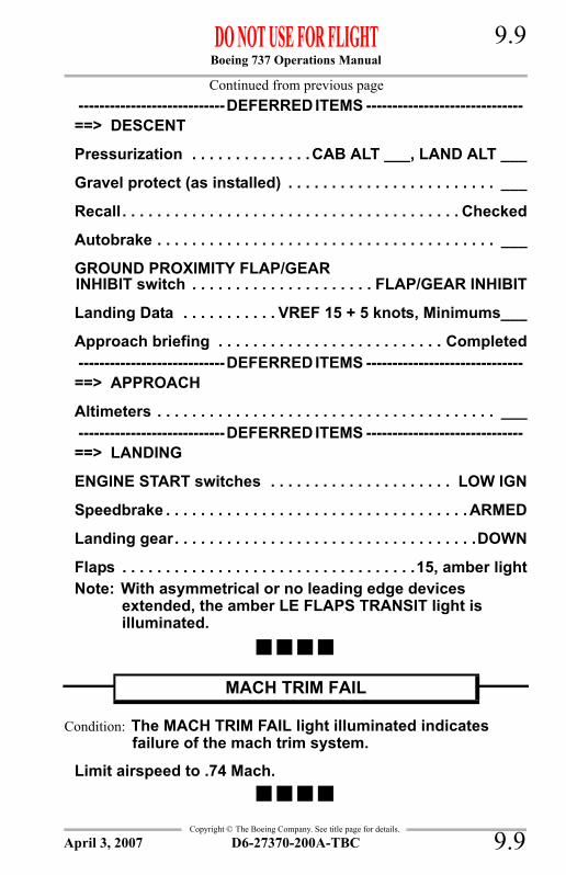
Boeing 737 Operations Manual 9.9
Copyright © The Boeing Company. See title page for details.
Continued from previous page----------------------------DEFERRED ITEMS ------------------------------==> DESCENT
Pressurization . . . . . . . . . . . . . .CAB ALT ___, LAND ALT ___
Gravel protect (as installed) . . . . . . . . . . . . . . . . . . . . . . . . ___
Recall. . . . . . . . . . . . . . . . . . . . . . . . . . . . . . . . . . . . . . . Checked
Autobrake . . . . . . . . . . . . . . . . . . . . . . . . . . . . . . . . . . . . . . . ___
GROUND PROXIMITY FLAP/GEARINHIBIT switch . . . . . . . . . . . . . . . . . . . . . FLAP/GEAR INHIBIT
Landing Data . . . . . . . . . . . VREF 15 + 5 knots, Minimums___
Approach briefing . . . . . . . . . . . . . . . . . . . . . . . . . . Completed----------------------------DEFERRED ITEMS ------------------------------==> APPROACH
Altimeters . . . . . . . . . . . . . . . . . . . . . . . . . . . . . . . . . . . . . . . ___----------------------------DEFERRED ITEMS ------------------------------==> LANDING
ENGINE START switches . . . . . . . . . . . . . . . . . . . . . LOW IGN
Speedbrake . . . . . . . . . . . . . . . . . . . . . . . . . . . . . . . . . . . ARMED
Landing gear. . . . . . . . . . . . . . . . . . . . . . . . . . . . . . . . . . .DOWN
Flaps . . . . . . . . . . . . . . . . . . . . . . . . . . . . . . . . . .15, amber lightNote: With asymmetrical or no leading edge devices
extended, the amber LE FLAPS TRANSIT light is illuminated.
Condition: The MACH TRIM FAIL light illuminated indicates failure of the mach trim system.
Limit airspeed to .74 Mach.
MACH TRIM FAIL
D6-27370-200A-TBC 9.9April 3, 2007

Boeing 737 Operations Manual 9.10
Copyright © The Boeing Company. See title page for details.
Condition: Continuing rotation of the stabilizer trim wheel in a manner not appropriate for flight conditions.
STABILIZER . . . . . . . . . . . . . . . . . . . . . . . .TRIM MANUALLY
Anticipate trim requirements.
Complete the normal DESCENT, APPROACH and LANDING checklists.
Establish proper airspeed and in-trim condition early on final approach.
Condition: The SPEED BRAKE DO NOT ARM light illuminated indicates a fault in the automatic speed brake system.
Note: Speed brakes may be used in flight.
Complete the normal DESCENT, APPROACH and LANDING checklists except do not arm speed brakes for landing.Manually deploy the speed brakes immediately upon touchdown.
RUNAWAY STABILIZER
CONTROL COLUMN. . . . . . . . . . . . . . . . . . . . . . HOLD FIRMLY
AUTOPILOT (if engaged) . . . . . . . . . . . . . . . . . . . .DISENGAGEDo not re-engage the autopilot.Control airplane pitch attitude manually with control column and main electric trim as required.
If runaway continues:
STABILIZER TRIM CUTOUT SWITCHES . . . . . . . . . . . . . . . . . . . . . . . . . . . . . . . . CUTOUT
If runaway continues:
STABILIZER TRIM WHEEL . . . . . . . . . . .GRASP & HOLD
SPEED BRAKE DO NOT ARM
D6-27370-200A-TBC9.10 April 1, 2005

Boeing 737 Operations Manual 9.11
Copyright © The Boeing Company. See title page for details.
Condition: The STAB OUT OF TRIM light illuminated indicates the autopilot is not trimming the stabilizer properly.
Note: Momentary illumination of the STAB OUT OF TRIM light during large changes in trim requirements is normal.
If the stabilizer is not trimming:
CONTROL COLUMN . . . . . . . . . . . . . . . . . . . HOLD FIRMLY
AUTOPILOT . . . . . . . . . . . . . . . . . . . . . . . . . . . .DISENGAGE
STABILIZER TRIM . . . . . . . . . . . . . . . . . . . . . AS REQUIRED
If the stabilizer fails to respond to electric trim inputs:
Accomplish the STABILIZER TRIM INOPERATIVE checklist.
STABILIZER OUT OF TRIM
D6-27370-200A-TBC 9.11April 1, 2005

Boeing 737 Operations Manual 9.12
Copyright © The Boeing Company. See title page for details.
Condition: The stabilizer fails to respond to electric trim inputs.
STABILIZER TRIM CUTOUT switches . . . . . . . . . . . . . . . . . . . . . . . . . . . . . . . . . . . . CUTOUT
[Autopilot is not available.]
Manual trim . . . . . . . . . . . . . . . . . . . . . . . . . . . . . . . . . . . . ApplyApply steady pressure on the manual trim handles until the desired trim is attained.If required, use force to cause the disconnect clutch to disengage. Approximately 1/2 turn of the stabilizer trim wheel may be needed.
Note: A maximum two-pilot effort on the trim wheels will not cause a cable or system failure.
Note: Handle(s) should be folded inside stabilizer trim wheel when not in use.
If the stabilizer can be trimmed manually:
Maintain in-trim airspeed until the start of the approach.
To reduce the force required to move the stabilizer, use an airspeed which results in an in-trim condition.
Continue to trim manually for the remainder of the flight.
Establish landing configuration early.
If the stabilizer can not be trimmed:
Anticipate higher than normal elevator forces during approach and landing.
The thrust reduction at flare will cause a nose down pitch.Note: If the failure could be due to ice accumulation,
descend to a warmer temperature and attempt again.
Note: Elevator control is sufficient to safely land the airplane regardless of stabilizer position.
Continued on next page
STABILIZER TRIM INOPERATIVE
D6-27370-200A-TBC9.12 April 3, 2007

Boeing 737 Operations Manual 9.13
Copyright © The Boeing Company. See title page for details.
Continued from previous page
Plan a flaps 15 landing.Set VREF 15.----------------------------DEFERRED ITEMS ------------------------------==> DESCENT
Pressurization . . . . . . . . . . . . . .CAB ALT ___, LAND ALT ___
Gravel protect (as installed) . . . . . . . . . . . . . . . . . . . . . . . . ___
Recall. . . . . . . . . . . . . . . . . . . . . . . . . . . . . . . . . . . . . . . Checked
Autobrake . . . . . . . . . . . . . . . . . . . . . . . . . . . . . . . . . . . . . . . ___
GROUND PROXIMITY FLAP/GEARINHIBIT switch . . . . . . . . . . . . . . . . . . . . . FLAP/GEAR INHIBIT
Landing Data . . . . . . . . . . . . . . . . . . . VREF 15, Minimums___
Approach briefing . . . . . . . . . . . . . . . . . . . . . . . . . . Completed
Go-around procedure . . . . . . . . . . . . . . . . . . . . . . . . . . ReviewAccomplish normal go-around procedure. Advance thrust to go-around smoothly and slowly to avoid excessive pitch-up.
----------------------------DEFERRED ITEMS ------------------------------==> APPROACH
Altimeters . . . . . . . . . . . . . . . . . . . . . . . . . . . . . . . . . . . . . . . ___----------------------------DEFERRED ITEMS ------------------------------==> LANDING
ENGINE START switches . . . . . . . . . . . . . . . . . . . . . LOW IGN
Speedbrake . . . . . . . . . . . . . . . . . . . . . . . . . . . . . . . . . . . ARMED
Landing gear. . . . . . . . . . . . . . . . . . . . . . . . . . . . . . . . . . .DOWN
Flaps . . . . . . . . . . . . . . . . . . . . . . . . . . . . . . . . . . 15, green light
D6-27370-200A-TBC 9.13April 3, 2007
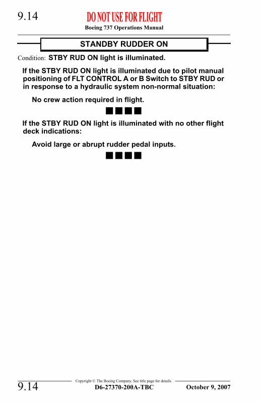
Boeing 737 Operations Manual 9.14
Copyright © The Boeing Company. See title page for details.
Condition: STBY RUD ON light is illuminated.
If the STBY RUD ON light is illuminated due to pilot manual positioning of FLT CONTROL A or B Switch to STBY RUD or in response to a hydraulic system non-normal situation:
No crew action required in flight.
If the STBY RUD ON light is illuminated with no other flight deck indications:
Avoid large or abrupt rudder pedal inputs.
STANDBY RUDDER ON
D6-27370-200A-TBC9.14 October 9, 2007

Boeing 737 Operations Manual 9.15
Copyright © The Boeing Company. See title page for details.
IntentionallyBlank
D6-27370-200A-TBC 9.15October 9, 2007

Boeing 737 Operations Manual 9.16
Copyright © The Boeing Company. See title page for details.
Condition: An uncommanded roll occurs when a new flap selection is made and/or a difference between the left and right flap indication is observed.
Flaps . . . . . . . . . . . . . . . . . . . . . . . . . . . . . . . . . . . . . . . . . . . .SetMove the flap lever to the neraest detent that is equal to or less than the smallest indicated flap position.
CAUTION: Do not attempt to move the trailing edge flaps with the alternate flaps switch as there is no asymmetry protection.
If flaps are 15 or more:
Set VREF for smallest flap position.Note: VREF + wind additive must not exceed the flap
placard speed for the next larger flap setting.
Continue checklist at DEFERRED ITEMS, DESCENT.
If flaps are 1 or greater and less than 15:
Set VREF 40 + 30 knots.
Check the appropriate Non–Normal Configuration Landing Distance table in the ADVISORY INFORMATION section of the Performance–Inflight chapter.
Continue checklist at DEFERRED ITEMS, DESCENT.
If flaps are less than 1:
Accomplish the TRAILING EDGE FLAPS UP LANDING checklist.
Continued on next page
TRAILING EDGE FLAP ASYMMETRY
D6-27370-200A-TBC9.16 October 9, 2007

Boeing 737 Operations Manual 9.17
Copyright © The Boeing Company. See title page for details.
Continued from previous page----------------------------DEFERRED ITEMS ------------------------------==> DESCENT
Pressurization . . . . . . . . . . . . . .CAB ALT ___, LAND ALT ___
Gravel protect (as installed) . . . . . . . . . . . . . . . . . . . . . . . . ___
Recall. . . . . . . . . . . . . . . . . . . . . . . . . . . . . . . . . . . . . . . Checked
Autobrake . . . . . . . . . . . . . . . . . . . . . . . . . . . . . . . . . . . . . . . ___
GROUND PROXIMITY FLAP/GEARINHIBIT switch . . . . . . . . . . . . . . . . . . . . . FLAP/GEAR INHIBIT
Landing Data . . . . . . . . . . . . . . . . . . VREF ___, Minimums___
Approach briefing . . . . . . . . . . . . . . . . . . . . . . . . . . Completed----------------------------DEFERRED ITEMS ------------------------------==> APPROACH
Altimeters . . . . . . . . . . . . . . . . . . . . . . . . . . . . . . . . . . . . . . . ___----------------------------DEFERRED ITEMS ------------------------------==> LANDING
ENGINE START switches . . . . . . . . . . . . . . . . . . . . . LOW IGN
Speedbrake . . . . . . . . . . . . . . . . . . . . . . . . . . . . . . . . . . . ARMED
Landing gear. . . . . . . . . . . . . . . . . . . . . . . . . . . . . . . . . . .DOWN
Flaps . . . . . . . . . . . . . . . . . . . . . . . . . . . . . . . . . ___, green light
D6-27370-200A-TBC 9.17October 9, 2007

Boeing 737 Operations Manual 9.18
Copyright © The Boeing Company. See title page for details.
Condition: The flap position indicators disagree with flap handle position and no asymmetry is indicated.
If indicated flap position is 30 or greater and less than 40:
Land using existing flaps.
Set VREF 30 for landing.Note: VREF 30 + wind additive must not exceed the flap
placard speed for flaps 40.
If indicated flap position is 15 or greater and less than 30:
Land using existing flaps.
Set VREF 15 for landing.Note: VREF 15 + wind additive must not exceed the flap
placard speed for the next larger flap setting.
Continue checklist at DEFERRED ITEMS, DESCENT.
If indicated flap position is less than 15:
Plan to extend flaps to 15 using alternate flap extension.Note: The drag penalty with the leading edge devices
extended may make it impossible to reach an alternate field.
Set VREF 15 for landing.
Continued on next page
TRAILING EDGE FLAP DISAGREE
D6-27370-200A-TBC9.18 April 9, 2008

Boeing 737 Operations Manual 9.19
Copyright © The Boeing Company. See title page for details.
Continued from previous page----------------------------DEFERRED ITEMS ------------------------------==> DESCENT
Pressurization . . . . . . . . . . . . . .CAB ALT ___, LAND ALT ___
Gravel protect (as installed) . . . . . . . . . . . . . . . . . . . . . . . . ___
Recall. . . . . . . . . . . . . . . . . . . . . . . . . . . . . . . . . . . . . . . Checked
Autobrake . . . . . . . . . . . . . . . . . . . . . . . . . . . . . . . . . . . . . . . ___
GROUND PROXIMITY FLAP/GEARINHIBIT switch . . . . . . . . . . . . . . . . . . . . . FLAP/GEAR INHIBIT
Landing Data . . . . . . . . . . . . . . . . . . . VREF 15, Minimums___
Approach briefing . . . . . . . . . . . . . . . . . . . . . . . . . . Completed----------------------------DEFERRED ITEMS ------------------------------==> APPROACH
Altimeters . . . . . . . . . . . . . . . . . . . . . . . . . . . . . . . . . . . . . . . ___
Continued on next page
D6-27370-200A-TBC 9.19October 9, 2007

Boeing 737 Operations Manual 9.20
Copyright © The Boeing Company. See title page for details.
Continued from previous page
If indicated flap position is less than 15:
ALTERNATE FLAPS masterswitch (210 knots maximum) . . . . . . . . . . . . . . . . . . . . ARMNote: Asymmetry protection is not provided when the
alternate flap extension system is used.Note: Alternate extension time to flaps 15 can take as
long as 2 minutes.
Flap lever . . . . . . . . . . . . . . . . . . . . . . . . . . . . . . . . . . . . . .SetDuring flap extension, set flap lever to next desired flap position.
Note: The landing gear configuration warning may sound if the flaps are between 10 and 15 and the landing gear are retracted.
ALTERNATE FLAPS positionswitch (210 knots maximum) . . . . . . . . . . . . . . . . . . .DOWN
Hold down to extend flaps to 15 on schedule. As flaps are extending, slow to respective maneuvering speed.
If trailing edge flap asymmetry occurs while using alternate flap extension:
ALTERNATE FLAPS positionswitch . . . . . . . . . . . . . . . . . . . . .Release immediately
Accomplish the TRAILING EDGE FLAP ASYMMETRY checklist.
If indicated flap position is less than 1 after attempting alternate flap extension:
Accomplish the TRAILING EDGE FLAPS UP LANDING checklist.
Continued on next page
D6-27370-200A-TBC9.20 April 9, 2008

Boeing 737 Operations Manual 9.21
Copyright © The Boeing Company. See title page for details.
Continued from previous page
If indicated flap position is less than 15: (continued)
If indicated flap position is 1 or greater and less than 15 after attempting alternate flap extension:
Land using existing flaps.
Set VREF 40 + 30 for landing.Note: The LE FLAPS TRANSIT light will remain
illuminated until the flaps approach the flaps 10 position.
----------------------------DEFERRED ITEMS ------------------------------==> LANDING
ENGINE START switches . . . . . . . . . . . . . . . . . . . . . LOW IGN
Speedbrake . . . . . . . . . . . . . . . . . . . . . . . . . . . . . . . . . . . ARMED
Landing gear. . . . . . . . . . . . . . . . . . . . . . . . . . . . . . . . . . .DOWN
Flaps . . . . . . . . . . . . . . . . . . . . . . . . . . . . . . . . . ___, green light
D6-27370-200A-TBC 9.21April 9, 2008

Boeing 737 Operations Manual 9.22
Copyright © The Boeing Company. See title page for details.
Condition: The trailing edge flaps do not move when flaps 1 is selected.
If no asymmetry exists:
Ensure that the TRAILING EDGE FLAP DISAGREE checklist has been accomplished.
If an asymmetry exists:
ALTERNATE FLAPS masterswitch (210 knots maximum) . . . . . . . . . . . . . . . . . . . . ARM
ALTERNATE FLAPS positionswitch . . . . . . . . . . . . . . . . . . . . . . . . . . . .Momentary DOWN
Verify that the leading edge devices annunciator indicates FULL EXT.
Note: The LE FLAPS TRANSIT light will remain illuminated.
If the leading edge devices annunciator does not indicate FULL EXT:
Do the ALL FLAPS UP LANDING checklist.
Burn off fuel to reduce touchdown speed.Set VREF 40 + 40 knots.Check the appropriate Non-Normal Configuration Landing Distance table in the ADVISORY INFORMATION section of the Performance-Inflight chapter.Maintain 210 knots until on final.On gravel deflector equipped airplanes, slow to 180 knots before lowering the landing gear.Limit bank angle to 15° when airspeed is less than 210 knots.
Continued on next page
TRAILING EDGE FLAPS UP LANDING
D6-27370-200A-TBC9.22 April 9, 2008

Boeing 737 Operations Manual 9.23
Copyright © The Boeing Company. See title page for details.
Continued from previous page----------------------------DEFERRED ITEMS ------------------------------==> DESCENT
Pressurization . . . . . . . . . . . . . .CAB ALT ___, LAND ALT ___
Gravel protect (as installed) . . . . . . . . . . . . . . . . . . . . . . . . ___
Recall. . . . . . . . . . . . . . . . . . . . . . . . . . . . . . . . . . . . . . . Checked
Autobrake . . . . . . . . . . . . . . . . . . . . . . . . . . . . . . . . . . . . . . . ___
GROUND PROXIMITY FLAP/GEARINHIBIT switch . . . . . . . . . . . . . . . . . . . . . FLAP/GEAR INHIBIT
Landing Data . . . . . . . . . . . . . . . VREF 40 + 40, Minimums___[A nuisance stick shaker may occur when slowing to VREF 40 + 40 at high gross weights and/or bank angles greater than 15°.]
Approach briefing . . . . . . . . . . . . . . . . . . . . . . . . . . Completed
GO-AROUND PROCEDURE. . . . . . . . . . . . . . . . . . . . . REVIEWDo the normal go-around procedure except:• Limit bank angle to 15° when airspeed is less than 210
knots.• Accelerate to 210 knots.• Do not exceed 210 knots with leading edge flaps
extended.----------------------------DEFERRED ITEMS ------------------------------==> APPROACH
Altimeters . . . . . . . . . . . . . . . . . . . . . . . . . . . . . . . . . . . . . . . ___----------------------------DEFERRED ITEMS ------------------------------==> LANDING
ENGINE START switches . . . . . . . . . . . . . . . . . . . . . LOW IGN
Speedbrake . . . . . . . . . . . . . . . . . . . . . . . . . . . . . . . . . . . ARMED
Landing gear. . . . . . . . . . . . . . . . . . . . . . . . . . . . . . . . . . .DOWN
Flaps . . . . . . . . . . . . . . . . . . . . . . . . . . . . . . . . . UP, amber light
FASTEN BELTS switch . . . . . . . . . . . . . . . . . . . . . . . . . . . . .ON
D6-27370-200A-TBC 9.23April 9, 2008

Boeing 737 Operations Manual 9.24
Copyright © The Boeing Company. See title page for details.
Condition: Uncommanded rudder pedal displacement or pedal kicks, or uncommanded yaw or roll.
If trailing edge flaps are extended, with no flap asymmetry and rudder pedals are normal. (May be accompanied by a loud bang.)
Flaps . . . . . . . . . . . . . . . . . . . . . . . . . . . . . . Retract to flaps 1on schedule
[Roll may be the result of trailing edge flap displacement due to a flap spindle fracture.]Consider accomplishing a go-around.
Plan a flaps 1 landing.
Set VREF 40 + 30.
Check the appropriate Non-Normal Configuration Landing Distance table in the ADVISORY INFORMATION section of the Performance-Inflight chapter.
Continue checklist at DEFERRED ITEMS, DESCENT.
If STBY RUD ON light is installed on the overhead Flight Control panel and is not placarded INOP:
Accomplish the JAMMED OR RESTRICTED FLIGHT CONTROLS Non-Normal Checklist.
Continued on next page
UNCOMMANDED RUDDER/YAW OR ROLL
Autopilot (if engaged) . . . . . . . . . . . . . . . . . . . . . . . Disengage
Maintain control of the airplane with all available flight controls. If roll is uncontrollable, immediately reduce pitch/angle of attack and increase airspeed. Do not attempt to maintain altitude until control is recovered.Verify thrust is symmetrical.
D6-27370-200A-TBC9.24 October 9, 2007
Boeing 737 Operations Manual 9.25
Copyright © The Boeing Company. See title page for details.
Continued from previous page
If STBY RUD ON light is not installed on the overhead Flight Control panel or is placarded INOP:
YAW DAMPER . . . . . . . . . . . . . . . . . . . . . . . . . . . . . . . . . OFF
If the yaw or roll stops:
Autopilot (if needed) . . . . . . . . . . . . . . . . . . . . . . . Engage
Accomplish the normal DESCENT, APPROACH and LANDING checklists.
Continued on next page
D6-27370-200A-TBC 9.25October 9, 2007

Boeing 737 Operations Manual 9.26
Copyright © The Boeing Company. See title page for details.
Continued from previous page
If STBY RUD ON light is not installed on the overhead Flight Control panel or is placarded INOP: (continued)
If yaw or roll is the result of uncommanded rudder displacement or pedal kicks:
Rudder trim . . . . . . . . . . . . . . . . . . . . . . . . . . . . . . .Center
Rudder pedals. . . . . . . . . . . . . . . . . . . . . . . Free & centerUse maximum force including a combined effort of both pilots, if required, to free and center the rudder pedals.
If rudder pedal position and movement are normal:
YAW DAMPER . . . . . . . . . . . . . . . . . . . . . . . . . . . . .ON
Accomplish the normal DESCENT, APPROACH and LANDING checklists.
Continued on next page
D6-27370-200A-TBC9.26 October 9, 2007

Boeing 737 Operations Manual 9.27
Copyright © The Boeing Company. See title page for details.
Continued from previous page
If STBY RUD ON light is not installed on the overhead Flight Control panel or is placarded INOP: (continued)
If yaw or roll is the result of uncommanded rudder displacement or pedal kicks: (continued)
If rudder pedal position or movement is not normal:
SYSTEM B FLIGHTCONTROL SWITCH . . . . . . . . . . . . . . . . . . STBY RUD
Land at the nearest suitable airport.Note: A slight rudder deflection may remain, but
continued rudder pedal pressure may help maintain an in-trim condition. Sufficient directional control is available on landing using differential braking and nose wheel steering.
Note: Crosswind capability may be reduced.Note: Do not use auto brakes.Note: Consider checking rudder freedom of
movement at a safe altitude using slow rudder inputs while in the landing configuration and at approach airspeed.
Accomplish the normal DESCENT, APPROACH and LANDING checklists.
Continued on next page
D6-27370-200A-TBC 9.27October 9, 2007

Boeing 737 Operations Manual 9.28
Copyright © The Boeing Company. See title page for details.
Continued from previous page----------------------------DEFERRED ITEMS ------------------------------==> DESCENT
Pressurization . . . . . . . . . . . . . . CAB ALT ___, LAND ALT ___
Gravel protect (as installed) . . . . . . . . . . . . . . . . . . . . . . . . ___
Recall . . . . . . . . . . . . . . . . . . . . . . . . . . . . . . . . . . . . . . Checked
Autobrake . . . . . . . . . . . . . . . . . . . . . . . . . . . . . . . . . . . . . . . ___
GROUND PROXIMITY FLAP/GEARINHIBIT switch . . . . . . . . . . . . . . . . . . . . . FLAP/GEAR INHIBIT
Landing Data . . . . . . . . . . VREF 40 + 30 knots, Minimums___
Approach briefing . . . . . . . . . . . . . . . . . . . . . . . . . . Completed----------------------------DEFERRED ITEMS ------------------------------==> APPROACH
Altimeters . . . . . . . . . . . . . . . . . . . . . . . . . . . . . . . . . . . . . . . ___----------------------------DEFERRED ITEMS ------------------------------==> LANDING
ENGINE START switches . . . . . . . . . . . . . . . . . . . . . .LOW IGN
Speedbrake . . . . . . . . . . . . . . . . . . . . . . . . . . . . . . . . . . . ARMED
Landing gear . . . . . . . . . . . . . . . . . . . . . . . . . . . . . . . . . .DOWN
Flaps . . . . . . . . . . . . . . . . . . . . . . . . . . . . . . . . . . . 1, green light
D6-27370-200A-TBC9.28 October 9, 2007

Boeing 737 Operations Manual 9.29
Copyright © The Boeing Company. See title page for details.
Condition: The YAW DAMPER light illuminated indicates the yaw damper is disengaged.
YAW DAMPER SWITCH . . . . . . . . . . . . . . . . . . . OFF THEN ON
If light remains illuminated:
YAW DAMPER SWITCH . . . . . . . . . . . . . . . . . . . . . . . . . . OFFDo not engage the autopilot roll channel above 30,000 feet.Do not exceed flaps 30 if crosswind exceeds 30 knots.
YAW DAMPER
D6-27370-200A-TBC 9.29October 9, 2007
Boeing 737 Operations Manual 9.30
Copyright © The Boeing Company. See title page for details.
IntentionallyBlank
D6-27370-200A-TBC9.30 October 9, 2007

Boeing 737 Operations Manual
Non-Normal Checklists Chapter NNCFlight Instruments, Display Section 10
Copyright © The Boeing Company. See title page for details.
Table of ContentsNNC.10 Non-Normal Checklists-Flight Instruments, DisplayAIRSPEED UNRELIABLE . . . . . . . . . . . . . . . . . . . . . . . . . . . . . 10.1
FLIGHT RECORDER OFF . . . . . . . . . . . . . . . . . . . . . . . . . . . . . . 10.1
D6-27370-200A-TBC TOC.10.1April 1, 2005

Boeing 737 Operations Manual
Non-Normal Checklists -Flight Instruments, Display
Copyright © The Boeing Company. See title page for details.
IntentionallyBlank
TOC.10.2 D6-27370-200A-TBC April 1, 2005

Boeing 737 Operations Manual 10.1
Copyright © The Boeing Company. See title page for details.
NNC.10 Non-Normal Checklists-Flight Instruments
Condition: Pitch attitude not consistent with existing phase of flight, altitude, thrust, and weight, or noise and/or low frequency buffeting.
Note: Erroneous or unreliable airspeed indications may be caused by blocked or frozen pitot-static system(s), or a severely damaged or missing radome.
Attitude and thrust information is provided in the Performance-Inflight section.
Condition: The flight recorder OFF light illuminated indicates that the recorder is not operating.
No crew action required.
AIRSPEED UNRELIABLE
AIRPLANE ATTITUDE/THRUST . . . . . . . . . . . . . . . . . . ADJUSTMaintain airplane control.
PITOT STATIC HEAT . . . . . . . . . . . . . . . . . . . . . . . . .CHECK ON
MACH/AIRSPEED INDICATORS . . . . . . . . . . . CROSS CHECK
FLIGHT RECORDER OFF
D6-27370-200A-TBC 10.1April 9, 2008

Boeing 737 Operations Manual 10.2
Copyright © The Boeing Company. See title page for details.
IntentionallyBlank
D6-27370-200A-TBC10.2 October 6, 2000
Boeing 737 Operations Manual
Non-Normal Checklists Chapter NNCFlight Management, Navigation Section 11
Copyright © The Boeing Company. See title page for details.
Table of ContentsNNC.11 Non-Normal Checklists-Flight Management, NavigationNO PROCEDURES . . . . . . . . . . . . . . . . . . . . . . . . . . . . . . . . . . . . 11.1
D6-27370-200A-TBC TOC.11.1April 1, 2005

Boeing 737 Operations Manual
Non-Normal Checklists -Flight Management, Navigation
Copyright © The Boeing Company. See title page for details.
IntentionallyBlank
TOC.11.2 D6-27370-200A-TBC April 1, 2005
Boeing 737 Operations Manual 11.1
Copyright © The Boeing Company. See title page for details.
NNC.11 Non-Normal Checklists-Flight Management, Navigation
Condition: There are no procedures for this section.
NO PROCEDURES
D6-27370-200A-TBC 11.1April 1, 2005

Boeing 737 Operations Manual 11.2
Copyright © The Boeing Company. See title page for details.
IntentionallyBlank
D6-27370-200A-TBC11.2 April 7, 2000

Boeing 737 Operations Manual
Non-Normal Checklists Chapter NNCFuel Section 12
Copyright © The Boeing Company. See title page for details.
Table of ContentsNNC.12 Non-Normal Checklists-FuelCROSSFEED SELECTOR INOPERATIVE . . . . . . . . . . . . . . . . . 12.1
ENGINE FUEL LEAK . . . . . . . . . . . . . . . . . . . . . . . . . . . . . . . . . . 12.2FILTER ICING . . . . . . . . . . . . . . . . . . . . . . . . . . . . . . . . . . . . . . . . 12.4FUEL HEAT VALVE FAILURE . . . . . . . . . . . . . . . . . . . . . . . . . . 12.5FUEL PUMP LOW PRESSURE . . . . . . . . . . . . . . . . . . . . . . . . . . 12.6FUEL TEMP LOW . . . . . . . . . . . . . . . . . . . . . . . . . . . . . . . . . . . . . 12.8INADVERTENT TRANSFER OF FUEL INTO AUX
TANK . . . . . . . . . . . . . . . . . . . . . . . . . . . . . . . . . . . . . . . . . . . . . 12.8INADVERTENT TRANSFER OF FUEL INTO CENTER
TANK . . . . . . . . . . . . . . . . . . . . . . . . . . . . . . . . . . . . . . . . . . . . . 12.9MINIMUM FUEL OPERATION . . . . . . . . . . . . . . . . . . . . . . . . . 12.10
D6-27370-200A-TBC TOC.12.1October 7, 2005

Boeing 737 Operations Manual
Non-Normal Checklists -Fuel
Copyright © The Boeing Company. See title page for details.
IntentionallyBlank
TOC.12.2 D6-27370-200A-TBC October 7, 2005

Boeing 737 Operations Manual 12.1
Copyright © The Boeing Company. See title page for details.
NNC.12 Non-Normal Checklists-Fuel
Condition: The crossfeed VALVE OPEN light remaining illuminated bright blue indicates the crossfeed valve position disagrees with the crossfeed selector position.
Valve Closed:
Flight conditions permitting, vary thrust to maintain fuel balance. If unable to maintain acceptable balance, land as soon as possible.
Valve Open:
Maintain fuel balance with selective use of fuel pumps.
CROSSFEED SELECTOR INOPERATIVE
D6-27370-200A-TBC 12.1April 1, 2005

Boeing 737 Operations Manual 12.2
Copyright © The Boeing Company. See title page for details.
Condition: An inflight engine fuel leak is suspected or confirmed.
One or more of the following may be evidence of a fuel leak:• visual observation of fuel spray from strut or engine• excessive fuel flow• total fuel quantity decreasing at an abnormal rate• fuel imbalance
Center tank FUEL PUMPS switches . . . . . . . . . . . . . . . . . . OFF
Auxiliary tank FUEL PUMPSswitches (as installed) . . . . . . . . . . . . . . . . . . . . . . . . . . . . . OFF
CROSSFEED selector . . . . . . . . . . . . . . . . . . . . . . . . . CLOSED
Identify an engine fuel leak by observing one main fuel tank quantity decreasing faster than the other.An increase in fuel imbalance of approximately 500 lbs or more in 30 minutes should be considered an engine fuel leak.Conditions permitting, visually check for an engine fuel leak.
If both main tank quantities decrease at the same rate:
Resume normal fuel management procedures.
Continued on next page
ENGINE FUEL LEAK
D6-27370-200A-TBC12.2 April 3, 2007

Boeing 737 Operations Manual 12.3
Copyright © The Boeing Company. See title page for details.
Continued from previous page
If an engine fuel leak is confirmed:
Thrust lever (affected engine) . . . . . . . . . . . . . . . . . . Close
ENGINE START LEVER (affected engine) . . . . . . . CUTOFF
Engine fire warning switch(affected engine) . . . . . . . . . . . . . . . . . . . . . . . . . . . . . . . Pull
To manually unlock the engine fire warning switch, press the override and pull.[Ensures wing mounted spar valve is closed.]
If the APU is available:
APU . . . . . . . . . . . . . . . . . . . . . . . . . . . . . . . . . . . . START
APU GENERATOR switch . . . . . . . . . . . . . . . . . . . . . .ON
Transponder mode selector(TCAS equipped airplanes) . . . . . . . . . . . . . . . . . . . . . . . TA
[Prevents climb commands which can exceed single engine performance capability.]
After engine shutdown, all remaining fuel can be used for the operating engine. Resume normal fuel management procedures.
Plan to land at the nearest suitable airport.
Accomplish ONE ENGINE INOPERATIVE LANDING checklist.
If a minimum fuel condition exists:
Main tank FUEL PUMPS switches . . . . . . . . . . . . . . . All ON
CROSSFEED selector . . . . . . . . . . . . . . . . . . . . . . . . . OPEN
Apply thrust changes slowly and smoothly. If a climb is required, maintain the minimum pitch attitude required for safe flight.
D6-27370-200A-TBC 12.3October 9, 2007

Boeing 737 Operations Manual 12.4
Copyright © The Boeing Company. See title page for details.
Condition: A FILTER ICING light illuminated indicates an iced or contaminated fuel filter.
FUEL PUMP SWITCHES . . . . . . . . . . . . . . . . . . . . . . . . . . . .ON[Fuel pressure should be supplied to engines at all times. Fuel heat on fuel pumps off may result in engine thrust deterioration.]
FUEL HEAT SWITCHES . . . . . . . . . . . . . . . . . . . . . . . . . . . . .ONIf any fuel filter icing light illuminates, turn both fuel heaters on for a one minute cycle. The FILTER ICING light should extinguish before the end of the cycle. One full cycle is recommended to restore the filter to its maximum filtration capacity.
If the FILTER ICING light remains illuminated:
With fuel temperature at or below 0 degrees centigrade, position both fuel heat switches ON for one minute every 30 minutes of flight.
FILTER ICING
D6-27370-200A-TBC12.4 April 1, 2005

Boeing 737 Operations Manual 12.5
Copyright © The Boeing Company. See title page for details.
Condition: The VALVE OPEN light remains illuminated.
Open position:
ENGINE OIL TEMPERATURELIMITATIONS . . . . . . . . . . . . . . . . . . . . . . . . . . . . .OBSERVE
Engine operation may be continued for the remainder of the flight provided that engine oil temperature is maintained within limits.
Closed position:
ENGINE FUEL FLOW. . . . . . . . . . . . . . . . . . . . . . . MONITOREngine operation may be continued for the remainder of the flight with the possibility of an eventual loss of power due to fuel icing.
FUEL HEAT VALVE FAILURE
D6-27370-200A-TBC 12.5April 1, 2005

Boeing 737 Operations Manual 12.6
Copyright © The Boeing Company. See title page for details.
Condition: A fuel pump LOW PRESSURE light illuminated indicates the related fuel pump output pressure is low.
Note: Fuel pump LOW PRESSURE lights may flicker when tank quantity is low and the airplane is in turbulent air or during climb or descent.
If one main tank fuel pump LOW PRESSURE light is illuminated:
MAIN TANK FUEL PUMP SWITCH . . . . . . . . . . . . . . . . . OFF[Sufficient fuel pressure is available for normal operation.]
If both main tank fuel pump LOW PRESSURE lights are illuminated:
Note: At high altitude, thrust deterioration or engine flameout may occur.
If one center tank fuel pump LOW PRESSURE light is illuminated:
CROSSFEED SELECTOR . . . . . . . . . . . . . . . . . . . . . . OPEN[Prevents fuel imbalance.]
CENTER TANK FUEL PUMP SWITCH(affected side) . . . . . . . . . . . . . . . . . . . . . . . . . . . . . . . . . OFF
When the other center tank fuel pump LOW PRESSURE light illuminates:
CROSSFEED SELECTOR. . . . . . . . . . . . . . . . . . . CLOSE
REMAINING CENTER TANKFUEL PUMP SWITCH . . . . . . . . . . . . . . . . . . . . . . . . . OFF
Continued on next page
FUEL PUMP LOW PRESSURE
D6-27370-200A-TBC12.6 April 1, 2005

Boeing 737 Operations Manual 12.7
Copyright © The Boeing Company. See title page for details.
Continued from previous page
If both center tank fuel pump LOW PRESSURE lights are illuminated:
BOTH CENTER TANKFUEL PUMP SWITCHES . . . . . . . . . . . . . . . . . . . . . . . . . OFF
Center tank fuel is unusable. Main tank fuel may not be sufficient for the planned flight.
If one auxiliary tank fuel pump LOW PRESSURE light is illuminated:
Sufficient fuel pressure is available for normal operation.
If both auxiliary tank fuel pump LOW PRESSURE lights are illuminated:
CENTER TANK FUELPUMP SWITCHES . . . . . . . . . . . . . . . . . . . . . . . . . . . . . . OFF
Use only main tank fuel for the remainder of the flight to avoid exceeding aft C.G. limits. Check fuel required to destination or suitable alternate. Remaining main tank fuel may not be sufficient for the planned flight.
D6-27370-200A-TBC 12.7April 1, 2005
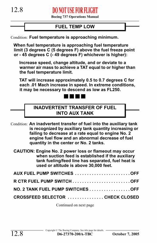
Boeing 737 Operations Manual 12.8
Copyright © The Boeing Company. See title page for details.
Condition: Fuel temperature is approaching minimum.
When fuel temperature is approaching fuel temperature limit (3 degrees C (5 degrees F) above the fuel freeze point or - 45 degrees C (- 49 degrees F) whichever is higher):
Increase speed, change altitude, and or deviate to a warmer air mass to achieve a TAT equal to or higher than the fuel temperature limit.
TAT will increase approximately 0.5 to 0.7 degrees C for each .01 Mach increase in speed. In extreme conditions, it may be necessary to descend as low as FL250.
Condition: An inadvertent transfer of fuel into the auxiliary tank is recognized by auxiliary tank quantity increasing or failing to decrease at a rate equal to engine No. 2 engine fuel flow and an abnormal decrease of fuel quantity in the center or No. 2 tanks.
CAUTION: Engine No. 2 power loss or flameout may occur when suction feed is established if the auxiliary tank fueling/feed line has separated, fuel heat is used or altitude is above 30,000 feet.
AUX FUEL PUMP SWITCHES . . . . . . . . . . . . . . . . . . . . . . . OFF
R CTR FUEL PUMP SWITCH . . . . . . . . . . . . . . . . . . . . . . . . OFF
NO. 2 TANK FUEL PUMP SWITCHES . . . . . . . . . . . . . . . . . OFF
CROSSFEED SELECTOR . . . . . . . . . . . . . . . CHECK CLOSED
Continued on next page
FUEL TEMP LOW
INADVERTENT TRANSFER OF FUEL INTO AUX TANK
D6-27370-200A-TBC12.8 October 7, 2005
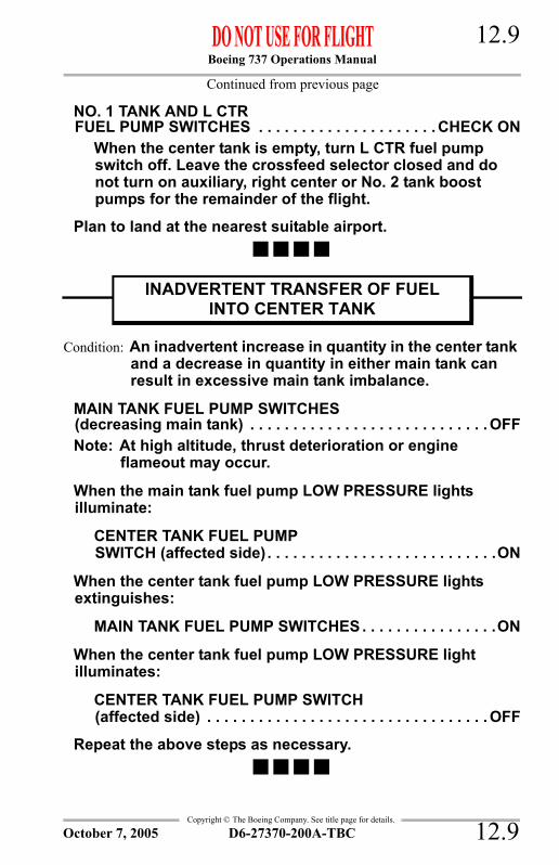
Boeing 737 Operations Manual 12.9
Copyright © The Boeing Company. See title page for details.
Continued from previous page
NO. 1 TANK AND L CTRFUEL PUMP SWITCHES . . . . . . . . . . . . . . . . . . . . . CHECK ON
When the center tank is empty, turn L CTR fuel pump switch off. Leave the crossfeed selector closed and do not turn on auxiliary, right center or No. 2 tank boost pumps for the remainder of the flight.
Plan to land at the nearest suitable airport.
Condition: An inadvertent increase in quantity in the center tank and a decrease in quantity in either main tank can result in excessive main tank imbalance.
MAIN TANK FUEL PUMP SWITCHES(decreasing main tank) . . . . . . . . . . . . . . . . . . . . . . . . . . . . OFFNote: At high altitude, thrust deterioration or engine
flameout may occur.
When the main tank fuel pump LOW PRESSURE lights illuminate:
CENTER TANK FUEL PUMPSWITCH (affected side) . . . . . . . . . . . . . . . . . . . . . . . . . . .ON
When the center tank fuel pump LOW PRESSURE lights extinguishes:
MAIN TANK FUEL PUMP SWITCHES . . . . . . . . . . . . . . . .ON
When the center tank fuel pump LOW PRESSURE light illuminates:
CENTER TANK FUEL PUMP SWITCH(affected side) . . . . . . . . . . . . . . . . . . . . . . . . . . . . . . . . . OFF
Repeat the above steps as necessary.
INADVERTENT TRANSFER OF FUEL INTO CENTER TANK
D6-27370-200A-TBC 12.9October 7, 2005

Boeing 737 Operations Manual 12.10
Copyright © The Boeing Company. See title page for details.
Condition: A minimum fuel condition exists when the quantity in any main tank is 1000 pounds or less.
The minimum fuel condition may be caused by an engine fuel leak. For indications of an engine fuel leak, check:
• total fuel remaining compared to planned fuel remaining• fuel flow indications, for an engine with excessive fuel
flow• individual tank quantities.
If there is any indication of an engine fuel leak:
Accomplish the ENGINE FUEL LEAK checklist.
If the minimum fuel condition occurs without any indication of an engine fuel leak:
MAIN TANK FUEL PUMP SWITCHES. . . . . . . . . . . .ALL ON
CROSSFEED SELECTOR . . . . . . . . . . . . . . . . . . . . . . OPEN[Ensures remaining fuel available to both engines.]
Apply thrust changes slowly and smoothly. If a climb is required, maintain the minimum pitch attitude required for safe flight.
[Minimizes the possibility of uncovering the fuel pumps.]
MINIMUM FUEL OPERATION
D6-27370-200A-TBC12.10 April 1, 2005

Boeing 737 Operations Manual
Non-Normal Checklists Chapter NNCHydraulics Section 13
Copyright © The Boeing Company. See title page for details.
Table of ContentsNNC.13 Non-Normal Checklists-HydraulicsHYDRAULIC PUMP LOW PRESSURE . . . . . . . . . . . . . . . . . . . 13.1
HYDRAULIC PUMP OVERHEAT . . . . . . . . . . . . . . . . . . . . . . . . 13.1LOSS OF SYSTEM A . . . . . . . . . . . . . . . . . . . . . . . . . . . . . . . . . . 13.2LOSS OF SYSTEM B . . . . . . . . . . . . . . . . . . . . . . . . . . . . . . . . . . 13.6MANUAL REVERSION . . . . . . . . . . . . . . . . . . . . . . . . . . . . . . . . 13.8STANDBY HYDRAULIC LOW PRESSURE . . . . . . . . . . . . . . 13.11STANDBY HYDRAULIC LOW QUANTITY . . . . . . . . . . . . . . 13.11
D6-27370-200A-TBC TOC.13.1April 9, 2008

Boeing 737 Operations Manual
Non-Normal Checklists -Hydraulics
Copyright © The Boeing Company. See title page for details.
IntentionallyBlank
TOC.13.2 D6-27370-200A-TBC April 9, 2008

Boeing 737 Operations Manual 13.1
Copyright © The Boeing Company. See title page for details.
NNC.13 Non-Normal Checklists-Hydraulics
Condition: A hydraulic pump LOW PRESSURE light illuminated indicates output pressure of the related pump is low.
HYDRAULIC PUMP SWITCH . . . . . . . . . . . . . . . . . . . . . . . . OFF[Intermittent illumination of the hydraulic pump LOW PRESSURE light may be the result of single electric pump operation and a high demand on the hydraulic system.]
Condition: A hydraulic pump OVERHEAT light illuminated indicates a fluid or motor overheat in the related electric motor-driven pump.
ELECTRIC HYDRAULIC PUMP SWITCH . . . . . . . . . . . . . . OFF[One pump provides adequate pressure for normal system operation.]
HYDRAULIC PUMP LOW PRESSURE
HYDRAULIC PUMP OVERHEAT
D6-27370-200A-TBC 13.1April 1, 2005

Boeing 737 Operations Manual 13.2
Copyright © The Boeing Company. See title page for details.
Condition: Both system A hydraulic pump LOW PRESSURE lights illuminated accompanied by low system A pressure indicates loss of system A. Other indications include:
• system A flight control LOW PRESSURE light illuminated
• FEEL DIFF PRESS light illuminated when flaps are up.
System A FLIGHT CONTROL switch . . . . . . . . . . . STBY RUD
System A HYDRAULIC PUMP switches . . . . . . . . . . . . . . . OFFNote: Inoperative items:
• ground spoilers• inboard flight spoilers• nose wheel steering
Note: Thrust reversers have standby pressure.Note: Inboard brakes have accumulator pressure only.
Plan for manual gear extension.Note: When the gear has been lowered manually, it cannot
be retracted. The drag penalty with gear extended may make it impossible to reach an alternate field.
Plan to extend flaps to 15 using alternate flap extension.Note: Alternate flap extension time to flaps 15 is
approximately 2 minutes.Note: Maximum airspeed is limited to 210 knots. The drag
penalty with the leading edge devices extended may make it impossible to reach an alternate field.
Continued on next page
LOSS OF SYSTEM A
D6-27370-200A-TBC13.2 April 7, 2006

Boeing 737 Operations Manual 13.3
Copyright © The Boeing Company. See title page for details.
Continued from previous page----------------------------DEFERRED ITEMS ------------------------------==> DESCENT
Pressurization . . . . . . . . . . . . . .CAB ALT ___, LAND ALT ___
Gravel protect (as installed) . . . . . . . . . . . . . . . . . . . . . . . . ___
Recall. . . . . . . . . . . . . . . . . . . . . . . . . . . . . . . . . . . . . . . Checked
Autobrake . . . . . . . . . . . . . . . . . . . . . . . . . . . . . . . . . . . . . . . ___
GROUND PROXIMITY FLAP/GEARINHIBIT switch . . . . . . . . . . . . . . . . . . . . . FLAP/GEAR INHIBIT
Landing Data . . . . . . . . . . . . . . . . . . . VREF 15, Minimums___
Approach briefing . . . . . . . . . . . . . . . . . . . . . . . . . . Completed
Continued on next page
D6-27370-200A-TBC 13.3April 9, 2008
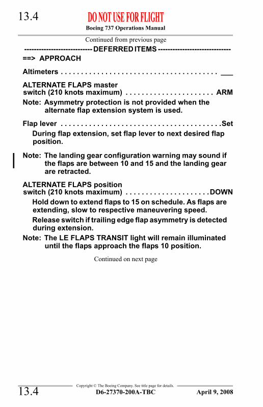
Boeing 737 Operations Manual 13.4
Copyright © The Boeing Company. See title page for details.
Continued from previous page----------------------------DEFERRED ITEMS ------------------------------==> APPROACH
Altimeters . . . . . . . . . . . . . . . . . . . . . . . . . . . . . . . . . . . . . . . ___
ALTERNATE FLAPS masterswitch (210 knots maximum) . . . . . . . . . . . . . . . . . . . . . . ARMNote: Asymmetry protection is not provided when the
alternate flap extension system is used.
Flap lever . . . . . . . . . . . . . . . . . . . . . . . . . . . . . . . . . . . . . . . .SetDuring flap extension, set flap lever to next desired flap position.
Note: The landing gear configuration warning may sound if the flaps are between 10 and 15 and the landing gear are retracted.
ALTERNATE FLAPS positionswitch (210 knots maximum) . . . . . . . . . . . . . . . . . . . . .DOWN
Hold down to extend flaps to 15 on schedule. As flaps are extending, slow to respective maneuvering speed.Release switch if trailing edge flap asymmetry is detected during extension.
Note: The LE FLAPS TRANSIT light will remain illuminated until the flaps approach the flaps 10 position.
Continued on next page
D6-27370-200A-TBC13.4 April 9, 2008

Boeing 737 Operations Manual 13.5
Copyright © The Boeing Company. See title page for details.
Continued from previous page----------------------------DEFERRED ITEMS ------------------------------==> LANDING
Landing gear lever . . . . . . . . . . . . . . . . . . . . . . . . . . . . . . . . OFF
On gravel deflector equipped airplanes, slow to 150 knots prior to gear extension.Manual gear extension handles . . . . . . . . . . . . . . . . . . . . . Pull
[The uplock is released when the handle is pulled to its limit. The related red landing gear indicator light illuminates, indicating uplock release.]
Wait 15 seconds after the last manual gear extension handle is pulled:
Landing gear lever . . . . . . . . . . . . . . . . . . . . . . . . . . . Down
ENGINE START switches . . . . . . . . . . . . . . . . . . . . . LOW IGN
Speedbrake . . . . . . . . . . . . . . . . . . . . . . . . . . . . . . . . . . . ARMED
Landing gear. . . . . . . . . . . . . . . . . . . . . . . . . . . . . . . . . . .DOWN
Flaps . . . . . . . . . . . . . . . . . . . . . . . . . . . . . . . . . . 15, green light
D6-27370-200A-TBC 13.5April 9, 2008

Boeing 737 Operations Manual 13.6
Copyright © The Boeing Company. See title page for details.
Condition: Both system B hydraulic pump LOW PRESSURE lights illuminated accompanied by low system B pressure indicates loss of system B. Other indications include:
• system B flight control LOW PRESSURE light illuminated
• FEEL DIFF PRESS light illuminated when flaps are up.
SYSTEM B FLIGHT CONTROL SWITCHES . . . . . . STBY RUD
SYSTEM B HYDRAULIC PUMP SWITCHES . . . . . . . . . . . . OFFNote: Inoperative items:
• outboard flight spoilers• autopilot• yaw damper.
Note: Outboard brakes have accumulator pressure only.
Autobrake . . . . . . . . . . . . . . . . . . . . . . . . . . . . . . . . . . . . . . . OFF
LOSS OF SYSTEM B
D6-27370-200A-TBC13.6 April 9, 2008

Boeing 737 Operations Manual 13.7
Copyright © The Boeing Company. See title page for details.
IntentionallyBlank
D6-27370-200A-TBC 13.7April 9, 2008

Boeing 737 Operations Manual 13.8
Copyright © The Boeing Company. See title page for details.
Condition: Both system A and B hydraulic pump LOW PRESSURE lights illuminated accompanied by low system A and B pressure indicates loss of both system A and B. Other indications include:
• system A and B flight control LOW PRESSURE lights illuminated.
System A and B FLIGHT CONTROL switches . . . . STBY RUD
System A and B HYDRAULIC PUMP switches . . . . . . . . . OFFNote: Inoperative items:
• ground spoilers• all flight spoilers• nose wheel steering• autobrakes• autopilot• yaw damper
Note: Thrust reversers have standby pressure. Trailing edge flaps have alternate electrical power. Inboard and outboard brakes have accumulator pressure only.
Plan to land at the nearest suitable airport.Plan for flaps 15 landing.Set VREF 15Plan for manual gear extension.Note: When the gear has been lowered manually, it cannot
be retracted. The drag penalty with gear extended may make it impossible to reach an alternate field.
Plan to extend flaps to 15 using alternate flap extension.Note: Alternate flap extension time to flaps 15 is
approximately 2 minutes.Note: Maximum airspeed is limited to 210 knots. The drag
penalty with the leading edge devices extended may make it impossible to reach an alternate field.
Continued on next page
MANUAL REVERSION
D6-27370-200A-TBC13.8 April 9, 2008

Boeing 737 Operations Manual 13.9
Copyright © The Boeing Company. See title page for details.
Continued from previous pageNote: The crosswind capability of the airplane is greatly
reduced.
On touchdown, apply steady brake pressure without modulating the brakes.Do not attempt to taxi the airplane after stopping.----------------------------DEFERRED ITEMS ------------------------------==> DESCENT
Pressurization . . . . . . . . . . . . . .CAB ALT ___, LAND ALT ___
Gravel protect (as installed) . . . . . . . . . . . . . . . . . . . . . . . . ___
Recall. . . . . . . . . . . . . . . . . . . . . . . . . . . . . . . . . . . . . . . Checked
Autobrake . . . . . . . . . . . . . . . . . . . . . . . . . . . . . . . . . . . . . . . OFF
GROUND PROXIMITY FLAP/GEARINHIBIT switch . . . . . . . . . . . . . . . . . . . . . FLAP/GEAR INHIBIT
Landing Data . . . . . . . . . . . . . . . . . . . VREF 15, Minimums___
Approach briefing . . . . . . . . . . . . . . . . . . . . . . . . . . Completed
Go-around Procedure . . . . . . . . . . . . . . . . . . . . . . . . . . ReviewAccomplish normal go-around procedure except:• Advance thrust to go around smoothly and slowly to
avoid excessive pitch up.• Prepare to trim.• Limit bank angle 15° when airspeed is less than 150
knots.
Continued on next page
D6-27370-200A-TBC 13.9April 9, 2008

Boeing 737 Operations Manual 13.10
Copyright © The Boeing Company. See title page for details.
Continued from previous page----------------------------DEFERRED ITEMS ------------------------------==> APPROACH
Altimeters . . . . . . . . . . . . . . . . . . . . . . . . . . . . . . . . . . . . . . . ___
ALTERNATE FLAPS masterswitch (210 knots maximum) . . . . . . . . . . . . . . . . . . . . . . ARMNote: Asymmetry protection is not provided when the
alternate flap extension system is used.
Flap lever . . . . . . . . . . . . . . . . . . . . . . . . . . . . . . . . . . . . . . . .SetDuring flap extension, set flap lever to next desired flap position.
Note: The landing gear configuration warning may sound if the flaps are between 10 and 15 and the landing gear are retracted.
ALTERNATE FLAPS positionswitch (210 knots maximum) . . . . . . . . . . . . . . . . . . . . .DOWN
Hold down to extend flaps to 15 on schedule. As flaps are extending, slow to respective maneuvering speed.Release switch if trailing edge flap asymmetry is detected during extension.
Note: The LE FLAPS TRANSIT light will remain illuminated until the flaps approach the flaps 10 position.
Continued on next page
D6-27370-200A-TBC13.10 April 9, 2008

Boeing 737 Operations Manual 13.11
Copyright © The Boeing Company. See title page for details.
Continued from previous page----------------------------DEFERRED ITEMS ------------------------------==> LANDING
Landing gear lever . . . . . . . . . . . . . . . . . . . . . . . . . . . . . . . . OFF
On gravel deflector equipped airplanes, slow to 150 knots prior to gear extension.Manual gear extension handles . . . . . . . . . . . . . . . . . . . . . Pull
[The uplock is released when the handle is pulled to its limit. The related red landing gear indicator light illuminates, indicating uplock release.]
Wait 15 seconds after the last manual gear extension handle is pulled:
Landing gear lever . . . . . . . . . . . . . . . . . . . . . . . . . . . Down
ENGINE START switches . . . . . . . . . . . . . . . . . . . . . LOW IGN
Speedbrake . . . . . . . . . . . . . . . . . . . . . . . . . . . . . . . . . . . ARMED
Landing gear. . . . . . . . . . . . . . . . . . . . . . . . . . . . . . . . . . .DOWN
Flaps . . . . . . . . . . . . . . . . . . . . . . . . . . . . . . . . . . 15, green light
Condition: The standby hydraulic LOW PRESSURE light illuminated indicates output pressure of the standby pump is low.
Note: With a loss of hydraulic system A and B, the rudder is inoperative.
Condition: The standby hydraulic LOW QUANTITY light illuminated indicates low quantity in the standby hydraulic reservoir.
STANDBY HYDRAULIC LOW PRESSURE
STANDBY HYDRAULIC LOW QUANTITY
D6-27370-200A-TBC 13.11April 9, 2008

Boeing 737 Operations Manual 13.12
Copyright © The Boeing Company. See title page for details.
IntentionallyBlank
D6-27370-200A-TBC13.12 April 9, 2008

Boeing 737 Operations Manual
Non-Normal Checklists Chapter NNCLanding Gear Section 14
Copyright © The Boeing Company. See title page for details.
Table of ContentsNNC.14 Non-Normal Checklists-Landing GearANTISKID INOPERATIVE . . . . . . . . . . . . . . . . . . . . . . . . . . . . . 14.1
AUTO BRAKE DISARM . . . . . . . . . . . . . . . . . . . . . . . . . . . . . . . 14.1BRAKE PRESSURE INDICATOR ZERO PSI . . . . . . . . . . . . . . . 14.2GEAR LEVER WILL NOT MOVE UP AFTER
TAKEOFF . . . . . . . . . . . . . . . . . . . . . . . . . . . . . . . . . . . . . . . . . . 14.3LANDING GEAR LEVER JAMMED IN THE UP
POSITION . . . . . . . . . . . . . . . . . . . . . . . . . . . . . . . . . . . . . . . . . 14.6MANUAL GEAR EXTENSION . . . . . . . . . . . . . . . . . . . . . . . . . 14.12PARTIAL OR GEAR UP LANDING . . . . . . . . . . . . . . . . . . . . . 14.20WHEEL WELL FIRE . . . . . . . . . . . . . . . . . . . . . . . . . . . . . . . . . . 14.22
D6-27370-200A-TBC TOC.14.1April 9, 2008

Boeing 737 Operations Manual
Non-Normal Checklists -Landing Gear
Copyright © The Boeing Company. See title page for details.
IntentionallyBlank
TOC.14.2 D6-27370-200A-TBC April 9, 2008

Boeing 737 Operations Manual 14.1
Copyright © The Boeing Company. See title page for details.
NNC.14 Non-Normal Checklists-Landing Gear
Condition: The ANTISKID INOP light illuminated indicates a system fault is detected by the antiskid system.
AUTO BRAKE SELECT SWITCH . . . . . . . . . . . . . . . . . . . . . OFFUse minimum braking consistent with runway conditions to reduce the possibility of a tire blowout.
Condition: The AUTO BRAKE DISARM light illuminated indicates the auto brake has disconnected after being set.
On ground:
AUTO BRAKE SELECT SWITCH . . . . . . . . . . . . . . . . . . OFF
If the AUTO BRAKE DISARM light remains illuminated:
Do not takeoff.
Inflight:
AUTO BRAKE SELECTSWITCH . . . . . . . . . . . . . . . . . . . . . . OFF THEN RESELECT
If the AUTO BRAKE DISARM light re-illuminates:
AUTO BRAKE SELECT SWITCH . . . . . . . . . . . . . . . . OFFUse manual brakes.
ANTISKID INOPERATIVE
AUTO BRAKE DISARM
D6-27370-200A-TBC 14.1October 9, 2007

Boeing 737 Operations Manual 14.2
Copyright © The Boeing Company. See title page for details.
Condition: The brake accumulator has no nitrogen precharge.
Accumulator braking is not available.Note: If hydraulic system indications are normal, brake
operation is unaffected.
BRAKE PRESSURE INDICATOR ZERO PSI
D6-27370-200A-TBC14.2 April 7, 2006

Boeing 737 Operations Manual 14.3
Copyright © The Boeing Company. See title page for details.
Condition: The landing gear lever cannot be placed to the UP position in the normal manner due to one or more of the following:
• failure of the landing gear lever lock solenoid• failure of the air/ground system
Note: On gravel deflector equipped airplanes, it is not possible to determine which failure has occurred because of the 180 knot landing gear airspeed limitation.
Landing Gear lever. . . . . . . . . . . . . . . . . . . . . . . . . . . . . .DOWN
If not equipped with a gravel deflector and the intermittent cabin altitude/configuration warning horn remains silent and the TAKEOFF CONFIG light (as installed) does not illuminate after the flaps are fully retracted and the thrust levers are beyond the vertical position:
Note: This condition indicates a failure of the landing gear lever lock solenoid.
Landing Gear Override trigger . . . . . . . . . . . . . . . . . . . . Pull
Landing Gear lever . . . . . . . . . . . . . . . . . . . . . . . . UP & OFF
Continued on next page
GEAR LEVER WILL NOT MOVE UP AFTER TAKEOFF
D6-27370-200A-TBC 14.3October 9, 2007

Boeing 737 Operations Manual 14.4
Copyright © The Boeing Company. See title page for details.
Continued from previous page
If equipped with a gravel deflector and the cabin altitude/configuration warning horn sounds and the TAKEOFF CONFIG light (as installed) illuminates when flaps are fully retracted:
Note: This condition indicates a failure of the air/ground system.
Landing Gear Lights C/B (P6) . . . . . . . . . . . . . . . . . . . . PullPlan to land at the nearest suitable airport.
CAUTION: Do not operate the speed brakes in flight.------------------------DEFERRED ITEMS ------------------------------==> DESCENT
Pressurization . . . . . . . . . . . . CAB ALT ___, LAND ALT ___
Gravel protect (as installed) . . . . . . . . . . . . . . . . . . . . . . ___
Recall . . . . . . . . . . . . . . . . . . . . . . . . . . . . . . . . . . . . Checked
Autobrake. . . . . . . . . . . . . . . . . . . . . . . . . . . . . . . . . . . . . OFF
Landing Data . . . . . . . . . . . . . . . . VREF ___, Minimums___
Approach briefing . . . . . . . . . . . . . . . . . . . . . . . . Completed------------------------DEFERRED ITEMS ------------------------------==> APPROACH
Altimeters . . . . . . . . . . . . . . . . . . . . . . . . . . . . . . . . . . . . . ___
Continued on next page
D6-27370-200A-TBC14.4 October 9, 2007

Boeing 737 Operations Manual 14.5
Copyright © The Boeing Company. See title page for details.
Continued from previous page
If equipped with a gravel deflector and the cabin altitude/configuration warning horn sounds and the TAKEOFF CONFIG light (as installed) illuminates when flaps are fully retracted: (continued)
------------------------DEFERRED ITEMS ------------------------------==> LANDING
ENGINE START switches . . . . . . . . . . . . . . . . . . . LOW IGN
Speedbrake . . . . . . . . . . . . . . . . . . . . . . . . . . . DOWN detent
Landing gear lever . . . . . . . . . . . . . . . . . . . . . . . . . . . Down
LANDING GEAR LIGHTS C/B (P6) . . . . . . . . . . . . . . . Reset
Landing gear . . . . . . . . . . . . . . . . . . . . . . . . . . . . . . . .DOWN
LANDING GEAR LIGHTS C/B (P6) . . . . . . . . . . . . . . . . . Pull
Flaps . . . . . . . . . . . . . . . . . . . . . . . . . . . . . . . ___, green light
Manually deploy the speed brakes immediately upon touchdown. Use manual braking.
D6-27370-200A-TBC 14.5October 9, 2007

Boeing 737 Operations Manual 14.6
Copyright © The Boeing Company. See title page for details.
Condition: The landing gear lever will not move from the UP position.
----------------------------DEFERRED ITEMS ------------------------------==> DESCENT
Pressurization . . . . . . . . . . . . . . CAB ALT ___, LAND ALT ___
On gravel deflector equipped airplanes, extend flaps to 15 and slow to 150 knots prior to gear extension.Landing gear override trigger . . . . . . . . . . . . . . . . . . . . . . . Pull
LANDING GEAR lever . . . . . . . . . . . . . . . . . . . . . . . . . . . .Down
If the landing gear lever moves down:
Landing gear indicator lights . . . . . . . . . . . . . . . . . . . Check
If all landing gear are down and locked:
Gravel protect (as installed) . . . . . . . . . . . . . . . . . . . ___
Recall . . . . . . . . . . . . . . . . . . . . . . . . . . . . . . . . . . Checked
Autobrake . . . . . . . . . . . . . . . . . . . . . . . . . . . . . . . . . . ___
Landing data . . . . . . . . . . . . . .VREF ___, MInimums ___
Approach briefing. . . . . . . . . . . . . . . . . . . . . . Completed
Do the normal APPROACH and LANDING checklists.
If all landing gear are not down and locked:
Do the MANUAL GEAR EXTENSION checklist.
Continued on next page
LANDING GEAR LEVER JAMMED IN THE UP POSITION
D6-27370-200A-TBC14.6 April 9, 2008

Boeing 737 Operations Manual 14.7
Copyright © The Boeing Company. See title page for details.
Continued from previous page
If the landing gear lever does not move down:
Total fuel quantity . . . . . . . . . . . . . . . . . . . . . . . . . . . . CheckManual gear extension may require up to 10 minutes to complete.Do not accomplish this checklist unless there is sufficient fuel to extend the gear and then complete an approach, with appropriate reserves.
If sufficient fuel is not available:
Do the PARTIAL OR GEAR UP LANDING checklist.
If sufficient fuel is available:
SYSTEM A FLIGHT CONTROLswitch . . . . . . . . . . . . . . . . . . . . . . . . . . . . . . . STBY RUD
SYSTEM A HYDRAULIC PUMPSswitches . . . . . . . . . . . . . . . . . . . . . . . . . . . . . . . . . . . OFF
WARNING:Do not repressurize hydraulic system A in flight or on the ground because the landing gear may retract.
Note: Inoperative items:• ground spoilers• inboard flight spoilers• nose wheel steering• inboard brakes have accumulator pressure
only• antiskid and automatic speed brakes are not
available if the landing gear lever is up. Use manual speed brakes and brake with caution.
Note: Thrust reversers have standby pressure.
Continued on next page
D6-27370-200A-TBC 14.7April 9, 2008
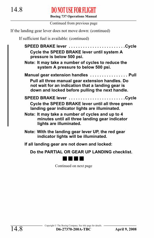
Boeing 737 Operations Manual 14.8
Copyright © The Boeing Company. See title page for details.
Continued from previous page
If the landing gear lever does not move down: (continued)
If sufficient fuel is available: (continued)
SPEED BRAKE lever . . . . . . . . . . . . . . . . . . . . . . . .CycleCycle the SPEED BRAKE lever until system A pressure is below 500 psi.
Note: It may take a number of cycles to reduce the system A pressure to below 500 psi.
Manual gear extension handles . . . . . . . . . . . . . . . . PullPull all three manual gear extension handles. Do not wait for an indication that a landing gear is down and locked before pulling the next handle.
SPEED BRAKE lever . . . . . . . . . . . . . . . . . . . . . . . .CycleCycle the SPEED BRAKE lever until all three green landing gear indicator lights are illuminated.
Note: It may take a number of cycles and up to 4 minutes until all three landing gear indicator lights are illuminated.
Note: With the landing gear lever UP, the red gear indicator lights will be illuminated.
If all landing gear are not down and locked:
Do the PARTIAL OR GEAR UP LANDING checklist.
Continued on next page
D6-27370-200A-TBC14.8 April 9, 2008
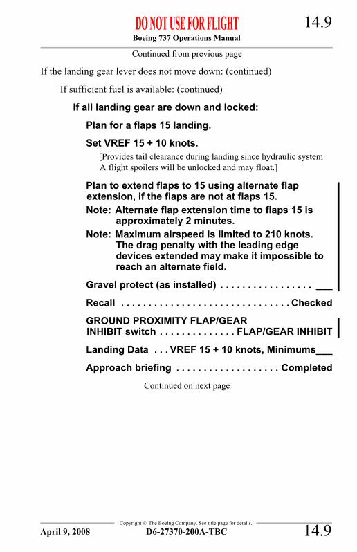
Boeing 737 Operations Manual 14.9
Copyright © The Boeing Company. See title page for details.
Continued from previous page
If the landing gear lever does not move down: (continued)
If sufficient fuel is available: (continued)
If all landing gear are down and locked:
Plan for a flaps 15 landing.
Set VREF 15 + 10 knots.[Provides tail clearance during landing since hydraulic system A flight spoilers will be unlocked and may float.]
Plan to extend flaps to 15 using alternate flap extension, if the flaps are not at flaps 15.Note: Alternate flap extension time to flaps 15 is
approximately 2 minutes.Note: Maximum airspeed is limited to 210 knots.
The drag penalty with the leading edge devices extended may make it impossible to reach an alternate field.
Gravel protect (as installed) . . . . . . . . . . . . . . . . . ___
Recall . . . . . . . . . . . . . . . . . . . . . . . . . . . . . . . Checked
GROUND PROXIMITY FLAP/GEARINHIBIT switch . . . . . . . . . . . . . . FLAP/GEAR INHIBIT
Landing Data . . . VREF 15 + 10 knots, Minimums___
Approach briefing . . . . . . . . . . . . . . . . . . . Completed
Continued on next page
D6-27370-200A-TBC 14.9April 9, 2008

Boeing 737 Operations Manual 14.10
Copyright © The Boeing Company. See title page for details.
Continued from previous page----------------------------DEFERRED ITEMS ------------------------------==> APPROACH
Altimeters . . . . . . . . . . . . . . . . . . . . . . . . . . . . . . . . . . . . . . . ___
If the flaps are not at flaps 15:
ALTERNATE FLAPS masterswitch (210 knots maximum) . . . . . . . . . . . . . . . . . . . . ARMNote: Asymmetry protection is not provided when the
alternate flap extension system is used.
Flap lever . . . . . . . . . . . . . . . . . . . . . . . . . . . . . . . . . . . . . .SetDuring flap extension, set flap lever to next desired flap position.
ALTERNATE FLAPS positionswitch (210 knots maximum) . . . . . . . . . . . . . . . . . . .DOWN
Hold down to extend flaps to 15 on schedule. As flaps are extending, slow to respective maneuvering speed.Release switch if trailing edge flap asymmetry is detected during extension.
Note: The LE FLAPS TRANSIT light will remain illuminated until the flaps approach the flaps 10 position.
----------------------------DEFERRED ITEMS ------------------------------==> LANDING
ENGINE START switches . . . . . . . . . . . . . . . . . . . . . .LOW IGN
Speedbrake . . . . . . . . . . . . . . . . . . . . . . . . . . . . . . DOWN detentUse manual speed brakes.
Landing gear . . . . . . . . . . . . . . . . . . . . . . . . . . . . . . . . . . .Down
Flaps . . . . . . . . . . . . . . . . . . . . . . . . . . . . . . . . . . 15, Green light
Note: Nose wheel steering is not available.
Note: Anti-skid is not available. Brake with caution.
D6-27370-200A-TBC14.10 April 9, 2008

Boeing 737 Operations Manual 14.11
Copyright © The Boeing Company. See title page for details.
IntentionallyBlank
D6-27370-200A-TBC 14.11April 9, 2008

Boeing 737 Operations Manual 14.12
Copyright © The Boeing Company. See title page for details.
Condition: All landing gear do not indicate down and locked when the landing gear lever is placed in the DOWN position or the landing gear lever is jammed in the OFF position.
Note: If a green landing gear indicator light is illuminated on either the center main panel or the overhead panel (as installed), the related landing gear is down and locked.
If three green landing gear indicator lights are illuminated on either the center main panel or the overhead panel (as installed):
Land normally.
Continued on next page
MANUAL GEAR EXTENSION
D6-27370-200A-TBC14.12 April 9, 2008

Boeing 737 Operations Manual 14.13
Copyright © The Boeing Company. See title page for details.
Continued from previous page
If a landing gear indicator light for the affected gear is not illuminated on either panel:
LANDING GEAR lever . . . . . . . . . . . . . . . . . . . . . . . . . . . OFFNote: On gravel deflector equipped airplanes, extend
flaps to 15 and slow to 150 knots prior to gear extension.
Manual gear extension handles . . . . . . . . . . . . . . . . . . . Pull[The uplock is released when the handle is pulled to its limit. The related red landing gear indicator light illuminates, indicating uplock release.]
Wait 15 seconds after the last manual gear extension handle is pulled.
LANDING GEAR lever . . . . . . . . . . . . . . . Down (if possible)
Landing gear indicator lights . . . . . . . . . . . . . . . . . . . CheckNote: If the landing gear lever is in the OFF position, the
red landing gear indicator lights will also be illuminated.
If all landing gear are down and locked:
If the landing gear lever is down:
Land normally.
If the landing gear lever is in the OFF position:
GROUND PROXIMITY FLAP/GEARINHIBIT switch . . . . . . . . . . . . . . FLAP/GEAR INHIBIT
Land normally.
Note: Nose wheel steering is not available.
Continued on next page
D6-27370-200A-TBC 14.13April 9, 2008
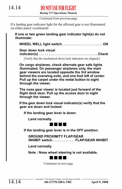
Boeing 737 Operations Manual 14.14
Copyright © The Boeing Company. See title page for details.
Continued from previous page
If a landing gear indicator light for the affected gear is not illuminated on either panel: (continued)
If one or two green landing gear indicator light(s) do not illuminate:
WHEEL WELL light switch. . . . . . . . . . . . . . . . . . . . . .ON
Gear down lock visualindicator(s) . . . . . . . . . . . . . . . . . . . . . . . . . . . . . . . Check
[Verify that the mechanical down lock indicators are aligned.]
On cargo airplanes, check alternate gear safe lights illuminated. On passenger airplanes only, the main gear viewers are located opposite the 3rd window behind the overwing exits, and one foot left of center. Pull up the carpet under the metal button to sight through the viewer.
The nose gear viewer is located just forward of the flight deck door. Pull up the access door to sight through the viewer.
If the gear down lock visual indicator(s) verify that the gear are down and locked:
If the landing gear lever is down:
Land normally.
If the landing gear lever is in the OFF position:
GROUND PROXIMITY FLAP/GEARINHIBIT switch . . . . . . . . . . . . FLAP/GEAR INHIBIT
Land normally.
Note : Nose wheel steering is not available.
Continued on next page
D6-27370-200A-TBC14.14 April 9, 2008
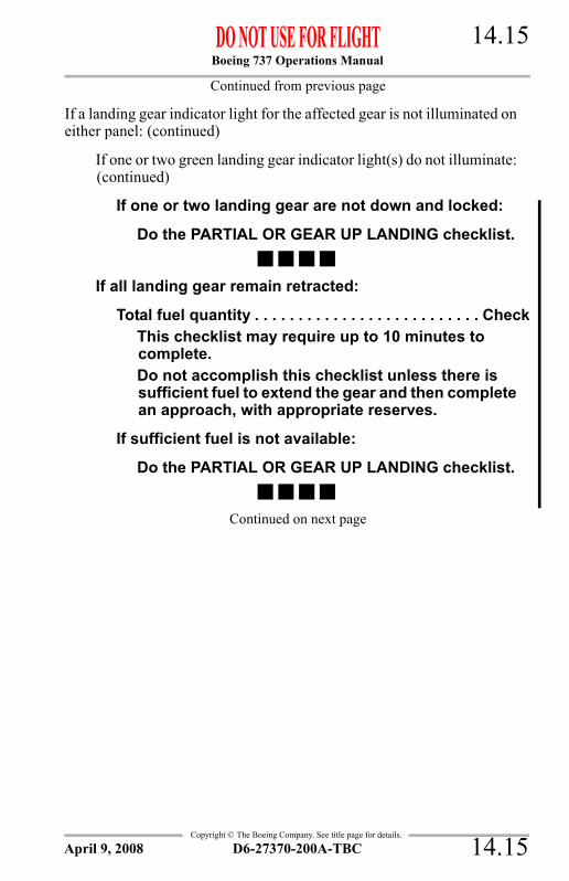
Boeing 737 Operations Manual 14.15
Copyright © The Boeing Company. See title page for details.
Continued from previous page
If a landing gear indicator light for the affected gear is not illuminated on either panel: (continued)
If one or two green landing gear indicator light(s) do not illuminate: (continued)
If one or two landing gear are not down and locked:
Do the PARTIAL OR GEAR UP LANDING checklist.
If all landing gear remain retracted:
Total fuel quantity . . . . . . . . . . . . . . . . . . . . . . . . . . CheckThis checklist may require up to 10 minutes to complete.Do not accomplish this checklist unless there is sufficient fuel to extend the gear and then complete an approach, with appropriate reserves.
If sufficient fuel is not available:
Do the PARTIAL OR GEAR UP LANDING checklist.
Continued on next page
D6-27370-200A-TBC 14.15April 9, 2008

Boeing 737 Operations Manual 14.16
Copyright © The Boeing Company. See title page for details.
Continued from previous page
If a landing gear indicator light for the affected gear is not illuminated on either panel: (continued)
If all landing gear remain retracted: (continued)
If sufficient fuel is available:
System A FLIGHT CONTROLswitch . . . . . . . . . . . . . . . . . . . . . . . . . . . . . STBY RUD
System A HYDRAULIC PUMPSswitches . . . . . . . . . . . . . . . . . . . . . . . . . . . . . . . . . OFF
WARNING:Do not repressurize hydraulic system A in flight or on the ground because the landing gear may retract.
Note: Inoperative items:• ground spoilers• inboard flight spoilers• nose wheel steering• inboard brakes have accumulator
pressure only• antiskid, auto brakes (airplanes with
INOP light) and automatic speed brakes are not available. Use manual speed brakes and brake with caution.
• antiskid and automatic speed brakes are not available. Use manual speed brakes and brake with caution.
Note: Thrust reversers have standby pressure.
SPEED BRAKE lever . . . . . . . . . . . . . . . . . . . . . .CycleCycle the SPEED BRAKE lever until system A pressure is below 500 psi.
Note: It may take a number of cycles to reduce the system A pressure to below 500 psi.
Note: On gravel equipped airplanes, slow to 150 knots prior to gear extension.
Continued on next page
D6-27370-200A-TBC14.16 April 9, 2008

Boeing 737 Operations Manual 14.17
Copyright © The Boeing Company. See title page for details.
Continued from previous page
If a landing gear indicator light for the affected gear is not illuminated on either panel: (continued)
If all landing gear remain retracted: (continued)
If sufficient fuel is available: (continued)
Manual gear extension handles . . . . . . . . . . . . . . PullPull all three manual gear extension handles. Do not wait for an indication that a landing gear is down and locked before pulling the next handle.
SPEED BRAKE lever . . . . . . . . . . . . . . . . . . . . . .CycleCycle the SPEED BRAKE lever until all three green landing gear indicator lights are illuminated.
Note: It may take a number of cycles and up to 4 minutes until all three landing gear indicator lights are illuminated.
Note: The red landing gear indicator lights may also be illuminated.
If all landing gear are not down and locked:
Do the PARTIAL OR GEAR UP LANDING checklist.
Continued on next page
D6-27370-200A-TBC 14.17April 9, 2008
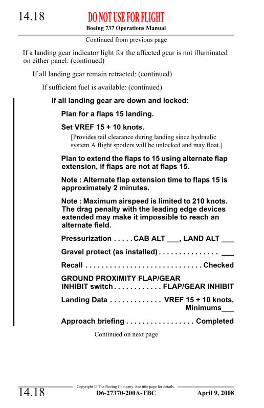
Boeing 737 Operations Manual 14.18
Copyright © The Boeing Company. See title page for details.
Continued from previous page
If a landing gear indicator light for the affected gear is not illuminated on either panel: (continued)
If all landing gear remain retracted: (continued)
If sufficient fuel is available: (continued)
If all landing gear are down and locked:
Plan for a flaps 15 landing.
Set VREF 15 + 10 knots.[Provides tail clearance during landing since hydraulic system A flight spoilers will be unlocked and may float.]
Plan to extend the flaps to 15 using alternate flap extension, if flaps are not at flaps 15.
Note : Alternate flap extension time to flaps 15 is approximately 2 minutes.
Note : Maximum airspeed is limited to 210 knots. The drag penalty with the leading edge devices extended may make it impossible to reach an alternate field.
Pressurization . . . . . CAB ALT ___, LAND ALT ___
Gravel protect (as installed) . . . . . . . . . . . . . . . ___
Recall . . . . . . . . . . . . . . . . . . . . . . . . . . . . . Checked
GROUND PROXIMITY FLAP/GEARINHIBIT switch . . . . . . . . . . . . FLAP/GEAR INHIBIT
Landing Data . . . . . . . . . . . . . VREF 15 + 10 knots, Minimums___
Approach briefing . . . . . . . . . . . . . . . . . Completed
Continued on next page
D6-27370-200A-TBC14.18 April 9, 2008
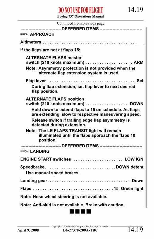
Boeing 737 Operations Manual 14.19
Copyright © The Boeing Company. See title page for details.
Continued from previous page----------------------------DEFERRED ITEMS ------------------------------==> APPROACH
Altimeters . . . . . . . . . . . . . . . . . . . . . . . . . . . . . . . . . . . . . . . ___
If the flaps are not at flaps 15:
ALTERNATE FLAPS masterswitch (210 knots maximum) . . . . . . . . . . . . . . . . . . . . ARMNote: Asymmetry protection is not provided when the
alternate flap extension system is used.
Flap lever . . . . . . . . . . . . . . . . . . . . . . . . . . . . . . . . . . . . . .SetDuring flap extension, set flap lever to next desired flap position.
ALTERNATE FLAPS positionswitch (210 knots maximum) . . . . . . . . . . . . . . . . . . .DOWN
Hold down to extend flaps to 15 on schedule. As flaps are extending, slow to respective maneuvering speed.Release switch if trailing edge flap asymmetry is detected during extension.
Note: The LE FLAPS TRANSIT light will remain illuminated until the flaps approach the flaps 10 position.
----------------------------DEFERRED ITEMS ------------------------------==> LANDING
ENGINE START switches . . . . . . . . . . . . . . . . . . . . . LOW IGN
Speedbrake . . . . . . . . . . . . . . . . . . . . . . . . . . . . . . DOWN detentUse manual speed brakes.
Landing gear. . . . . . . . . . . . . . . . . . . . . . . . . . . . . . . . . . . Down
Flaps . . . . . . . . . . . . . . . . . . . . . . . . . . . . . . . . . . 15, Green light
Note: Nose wheel steering is not available.
Note: Anti-skid is not available. Brake with caution.
D6-27370-200A-TBC 14.19April 9, 2008

Boeing 737 Operations Manual 14.20
Copyright © The Boeing Company. See title page for details.
Condition: All landing gear do not indicate down and locked after attempting manual gear extension.
Brief crew and passengers on emergency landing and evacuation procedures.Burn off fuel to reduce touchdown speed.Plan a flaps 40 landing.Set VREF 40.----------------------------DEFERRED ITEMS ------------------------------==> DESCENT
Pressurization . . . . . . . . . . . . . . CAB ALT ___, LAND ALT ___
Gravel protect (as installed) . . . . . . . . . . . . . . . . . . . . . . . . ___
Recall . . . . . . . . . . . . . . . . . . . . . . . . . . . . . . . . . . . . . . Checked
AURAL WARN C/B (P6) . . . . . . . . . . . . . . . . . . . . . . . . . . . . Pull[Prevents warning horn with gear retracted and landing flaps selected.]
AUTO SPEED BRAKE C/B (P6) . . . . . . . . . . . . . . . . . . . . . . Pull
GROUND PROXIMITY FLAP/GEARINHIBIT switch . . . . . . . . . . . . . . . . . . . . . FLAP/GEAR INHIBIT
STANDBY POWER switch . . . . . . . . . . . . . . . . . . . . . . . . . . BAT
Autobrake . . . . . . . . . . . . . . . . . . . . . . . . . . . . . . . . . . . . . . . OFF
Landing Data . . . . . . . . . . . . . . . . . . . VREF 40, Minimums___
Approach briefing . . . . . . . . . . . . . . . . . . . . . . . . . . Completed
Continued on next page
PARTIAL OR GEAR UP LANDING
D6-27370-200A-TBC14.20 April 9, 2008
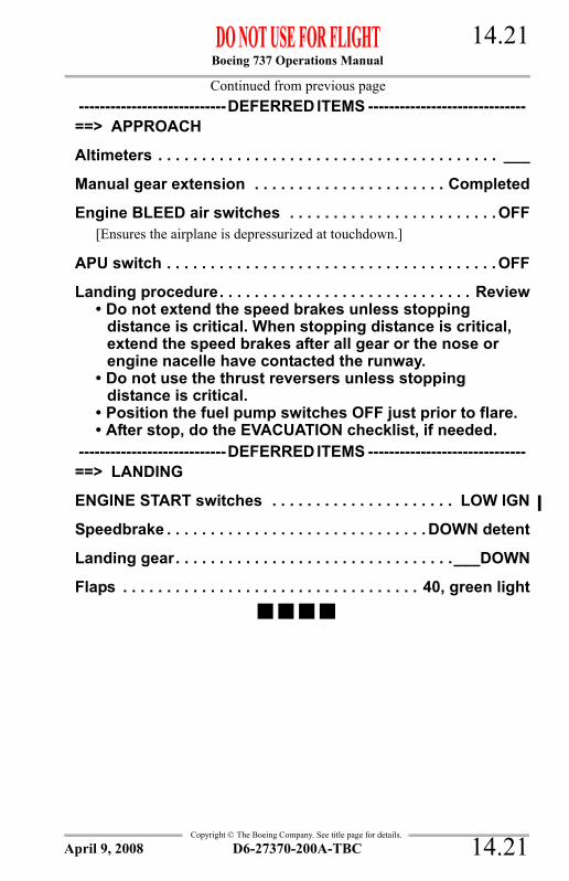
Boeing 737 Operations Manual 14.21
Copyright © The Boeing Company. See title page for details.
Continued from previous page----------------------------DEFERRED ITEMS ------------------------------==> APPROACH
Altimeters . . . . . . . . . . . . . . . . . . . . . . . . . . . . . . . . . . . . . . . ___
Manual gear extension . . . . . . . . . . . . . . . . . . . . . . Completed
Engine BLEED air switches . . . . . . . . . . . . . . . . . . . . . . . . OFF[Ensures the airplane is depressurized at touchdown.]
APU switch . . . . . . . . . . . . . . . . . . . . . . . . . . . . . . . . . . . . . . OFF
Landing procedure. . . . . . . . . . . . . . . . . . . . . . . . . . . . . Review• Do not extend the speed brakes unless stopping
distance is critical. When stopping distance is critical, extend the speed brakes after all gear or the nose or engine nacelle have contacted the runway.
• Do not use the thrust reversers unless stopping distance is critical.
• Position the fuel pump switches OFF just prior to flare.• After stop, do the EVACUATION checklist, if needed.
----------------------------DEFERRED ITEMS ------------------------------==> LANDING
ENGINE START switches . . . . . . . . . . . . . . . . . . . . . LOW IGN
Speedbrake . . . . . . . . . . . . . . . . . . . . . . . . . . . . . . DOWN detent
Landing gear. . . . . . . . . . . . . . . . . . . . . . . . . . . . . . . .___DOWN
Flaps . . . . . . . . . . . . . . . . . . . . . . . . . . . . . . . . . . 40, green light
D6-27370-200A-TBC 14.21April 9, 2008

Boeing 737 Operations Manual 14.22
Copyright © The Boeing Company. See title page for details.
Condition: A fire is detected in the main wheel well.
Observe gear EXTEND limit speed (270K/.82M.)
LANDING GEAR LEVER . . . . . . . . . . . . . . . . . . . . . . . . .DOWNNote: If the airplane is equipped with a nose wheel gravel
deflector system, extend the main landing gear manually with the landing gear lever in the OFF position to avoid extending the nose gear at high speed. (Nose gear extension speed is 180 knots.)
If the landing gear must be retracted for airplane performance, leave the landing gear extended for 20 minutes after the WHEEL WELL fire warning light has extinguished.
LANDING GEAR LEVER (if required)(235 Kts maximum) . . . . . . . . . . . . . . . . . . . . . . . . UP & OFF
Plan to land at the nearest suitable airport.
WHEEL WELL FIRE
D6-27370-200A-TBC14.22 April 9, 2008

Boeing 737 Operations Manual
Non-Normal Checklists Chapter NNCWarning Systems Section 15
Copyright © The Boeing Company. See title page for details.
Table of ContentsNNC.15 Non-Normal Checklists-Warning SystemsALTITUDE ALERT . . . . . . . . . . . . . . . . . . . . . . . . . . . . . . . . . . . . 15.1
GROUND PROXIMITY INOP . . . . . . . . . . . . . . . . . . . . . . . . . . . 15.1OVERSPEED . . . . . . . . . . . . . . . . . . . . . . . . . . . . . . . . . . . . . . . . 15.1TAKEOFF CONFIGURATION . . . . . . . . . . . . . . . . . . . . . . . . . 15.1WARNING HORN -CABIN ALTITUDE OR
CONFIGURATION . . . . . . . . . . . . . . . . . . . . . . . . . . . . . . . . . 15.2
D6-27370-200A-TBC TOC.15.1October 9, 2007

Boeing 737 Operations Manual
Non-Normal Checklists -Warning Systems
Copyright © The Boeing Company. See title page for details.
IntentionallyBlank
TOC.15.2 D6-27370-200A-TBC October 9, 2007

Boeing 737 Operations Manual 15.1
Copyright © The Boeing Company. See title page for details.
NNC.15 Non-Normal Checklists-Warning Systems
Condition: The ALTITUDE ALERT indication indicates that the airplane is approaching or deviating from a selected altitude.
Reset selected altitude (if necessary.)Maintain appropriate altitude.
Condition: The ground proximity INOP light illuminated indicates GPWS alerts may not be provided.
Note: Some or all GPWS alerts are not available. GPWS alerts which occur are valid.
Condition: The mach/airspeed warning clacker is activated when the maximum operating speed of Vmo/Mmo is exceeded.
Condition: The intermittent cabin altitude/configuration warning horn sounds and the TAKEOFF CONFIG light (as installed) illuminates on the ground when advancing the thrust levers to takeoff thrust.
ALTITUDE ALERT
GROUND PROXIMITY INOP
OVERSPEED
Reduce thrust and, if required, adjust attitude to reduce airspeed to less than Vmo/Mmo.
TAKEOFF CONFIGURATION
Assure proper airplane takeoff configuration.
D6-27370-200A-TBC 15.1October 9, 2007

Boeing 737 Operations Manual 15.2
Copyright © The Boeing Company. See title page for details.
Condition: An intermittent or steady warning horn sounds:• In flight, the intermittent warning horn sounds
and the CABIN ALTITUDE light (as installed) illuminates, indicating the cabin altitude is at or above 10,000 feet
• On the ground, the intermittent warning horn sounds and the TAKEOFF CONFIG light (as installed) illuminates, indicating an improper takeoff configuration when advancing the thrust levers to takeoff thrust
• In flight, the steady horn warning horn sounds, indicating an improper landing configuration.
WARNING HORN -CABIN ALTITUDE OR CONFIGURATION
If the intermittent warning horn sounds and the CABIN ALTITUDE light (as installed) illuminates in flight:
Oxygen masks and regulators . . . . . . . . . . . . . . . On, 100%
Crew communications . . . . . . . . . . . . . . . . . . . . . Establish
Do the CABIN ALTITUDE WARNING OR RAPID DEPRESSURIZATION checklist.
If the intermittent warning horn sounds and the TAKEOFF CONFIG light (as installed) illuminates on the ground:
Assure proper airplane takeoff configuration.
If the steady warning horn sounds in flight:
Assure proper airplane landing configuration.
D6-27370-200A-TBC15.2 October 9, 2007

Boeing 737 Operations Manual
Manuevers Chapter MANTable of Contents Section 0
Copyright © The Boeing Company. See title page for details.
MAN.0 Manuevers-Table of Contents
Introduction . . . . . . . . . . . . . . . . . . . . . . . . . . . . . . . . . . . . . . MAN.05.1
General . . . . . . . . . . . . . . . . . . . . . . . . . . . . . . . . . . . . . . . . . MAN.05.1Non-Normal Maneuvers . . . . . . . . . . . . . . . . . . . . . . . . . . . MAN.05.1Flight Patterns . . . . . . . . . . . . . . . . . . . . . . . . . . . . . . . . . . . MAN.05.1
Non-Normal Maneuvers . . . . . . . . . . . . . . . . . . . . . . . . . . . . . MAN.1.1
Approach to Stall Recovery . . . . . . . . . . . . . . . . . . . . . . . . . . MAN.1.1Rejected Takeoff . . . . . . . . . . . . . . . . . . . . . . . . . . . . . . . . . . MAN.1.1Terrain Avoidance . . . . . . . . . . . . . . . . . . . . . . . . . . . . . . . . . MAN.1.3
Ground Proximity Caution . . . . . . . . . . . . . . . . . . . . . . . . MAN.1.3Ground Proximity Warning . . . . . . . . . . . . . . . . . . . . . . . MAN.1.4
Traffic Avoidance (airplanes with TCAS) . . . . . . . . . . . . . . . MAN.1.5Upset Recovery . . . . . . . . . . . . . . . . . . . . . . . . . . . . . . . . . . . MAN.1.6
Nose High Recovery . . . . . . . . . . . . . . . . . . . . . . . . . . . . . MAN.1.7Nose Low Recovery . . . . . . . . . . . . . . . . . . . . . . . . . . . . . MAN.1.7
Windshear . . . . . . . . . . . . . . . . . . . . . . . . . . . . . . . . . . . . . . . MAN.1.8Windshear Escape Maneuver . . . . . . . . . . . . . . . . . . . . . . MAN.1.8
Flight Patterns . . . . . . . . . . . . . . . . . . . . . . . . . . . . . . . . . . . . . MAN.2.1
Takeoff . . . . . . . . . . . . . . . . . . . . . . . . . . . . . . . . . . . . . . . . . . MAN.2.1ILS Approach . . . . . . . . . . . . . . . . . . . . . . . . . . . . . . . . . . . . . MAN.2.2Non-ILS Instrument Approaches . . . . . . . . . . . . . . . . . . . . . . MAN.2.3Circling Approach . . . . . . . . . . . . . . . . . . . . . . . . . . . . . . . . . MAN.2.4Visual Traffic Pattern . . . . . . . . . . . . . . . . . . . . . . . . . . . . . . . MAN.2.5Go–Around and Missed Approach . . . . . . . . . . . . . . . . . . . . MAN.2.6
D6-27370-200A-TBC MAN.TOC.0.1April 9, 2008

Boeing 737 Operations Manual
Manuevers -Table of Contents
Copyright © The Boeing Company. See title page for details.
IntentionallyBlank
MAN.TOC.0.2 D6-27370-200A-TBC April 9, 2008

Boeing 737 Operations Manual
Maneuvers Chapter MANIntroduction Section 05
Copyright © The Boeing Company. See title page for details.
MAN.05 Maneuvers-IntroductionGeneralNon-Normal Maneuvers and Flight Patterns are included for training and review purposes.
Non-Normal ManeuversFlight crews are expected to do non-normal maneuvers from memory.
Flight PatternsFlight patterns show procedures for some all-engine and engine-inoperative situations.Flight patterns do not include all procedural items, but show required/recommended:• configuration changes• thrust changes• Mode Control Panel (MCP) changes• pitch mode and roll mode changes• checklist calls.
D6-27370-200A-TBC MAN.05.1April 9, 2008

Boeing 737 Operations Manual
Maneuvers -Introduction
Copyright © The Boeing Company. See title page for details.
IntentionallyBlank
MAN.05.2 D6-27370-200A-TBC April 9, 2008
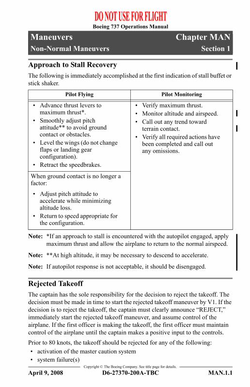
Boeing 737 Operations Manual
Maneuvers Chapter MANNon-Normal Maneuvers Section 1
Copyright © The Boeing Company. See title page for details.
MAN.1 Maneuvers-Non-Normal ManeuversApproach to Stall RecoveryThe following is immediately accomplished at the first indication of stall buffet or stick shaker.
Note: *If an approach to stall is encountered with the autopilot engaged, apply maximum thrust and allow the airplane to return to the normal airspeed.
Note: **At high altitude, it may be necessary to descend to accelerate.
Note: If autopilot response is not acceptable, it should be disengaged.
Rejected TakeoffThe captain has the sole responsibility for the decision to reject the takeoff. The decision must be made in time to start the rejected takeoff maneuver by V1. If the decision is to reject the takeoff, the captain must clearly announce “REJECT,” immediately start the rejected takeoff maneuver, and assume control of the airplane. If the first officer is making the takeoff, the first officer must maintain control of the airplane until the captain makes a positive input to the controls.Prior to 80 knots, the takeoff should be rejected for any of the following:• activation of the master caution system• system failure(s)
Pilot Flying Pilot Monitoring
• Advance thrust levers to maximum thrust*.
• Smoothly adjust pitch attitude** to avoid ground contact or obstacles.
• Level the wings (do not change flaps or landing gear configuration).
• Retract the speedbrakes.
• Verify maximum thrust.• Monitor altitude and airspeed.• Call out any trend toward
terrain contact.• Verify all required actions have
been completed and call out any omissions.
When ground contact is no longer a factor:
• Adjust pitch attitude to accelerate while minimizing altitude loss.
• Return to speed appropriate for the configuration.
D6-27370-200A-TBC MAN.1.1April 9, 2008

Boeing 737 Operations Manual
Maneuvers -Non-Normal Maneuvers
Copyright © The Boeing Company. See title page for details.
• unusual noise or vibration• tire failure• abnormally slow acceleration• unsafe takeoff configuration warning• fire or fire warning• engine failure• if a side window opens• if the airplane is unsafe or unable to fly.
Above 80 knots and prior to V1, the takeoff should be rejected for any of the following:• fire or fire warning• engine failure• if the airplane is unsafe of unable to fly.
During the takeoff, the crewmember observing the non-normal situation will immediately call it out as clearly as possible.
Captain First Officer
Without delay:
Simultaneously close the thrust levers and apply maximum manual wheel brakes.
Raise the SPEED BRAKE lever.
Apply maximum reverse thrust consistent with conditions.
Continue maximum braking until certain the airplane will stop on the runway.
Verify actions as follows:
Thrust levers closed.
Maximum brakes applied.
Verify SPEED BRAKE lever UP and call “SPEED BRAKES UP.” If SPEED BRAKE lever is not UP, call “SPEED BRAKES NOT UP.”
Reverse thrust applied.
Call out any omitted action items.
Field length permitting: Initiate movement of the reverse thrust levers to reach the reverse idle detent by taxi speed.
Call out 60 knots.
Communicate the reject decision to the control tower and cabin as soon as practical.
MAN.1.2 D6-27370-200A-TBC April 9, 2008

Boeing 737 Operations Manual
Maneuvers -Non-Normal Maneuvers
Copyright © The Boeing Company. See title page for details.
Terrain Avoidance
Ground Proximity CautionAccomplish the following maneuver for any of these aural alerts:• CAUTION TERRAIN• TERRAIN AHEAD (JAA)• SINK RATE• TERRAIN, TERRAIN• DON’T SINK• TOO LOW FLAPS• TOO LOW GEAR• TOO LOW TERRAIN• GLIDESLOPE• BANK ANGLE
The below glideslope deviation alert may be cancelled or inhibited for:• localizer or backcourse approach• circling approach from an ILS• when conditions require a deliberate approach below glideslope• unreliable glideslope signal.
When the airplane is stopped, perform procedures as required.
Review Brake Cooling Schedule for brake cooling time and precautions (refer to Performance Inflight Chapter).
Consider the following:
• The possibility of wheel fuse plugs melting• The need to clear the runway• The requirement for remote parking• Wind direction in case of fire• Alerting fire equipment• Not setting the parking brake unless passenger evacuation is necessary• Advising the ground crew of the hot brake hazard• Advising passengers of the need to remain seated or evacuate• Completion of Non-Normal checklist (if appropriate) for conditions
which caused the RTO.
Pilot Flying Pilot Monitoring
Correct the flight path or the airplane configuration.
D6-27370-200A-TBC MAN.1.3April 9, 2008

Boeing 737 Operations Manual
Maneuvers -Non-Normal Maneuvers
Copyright © The Boeing Company. See title page for details.
Note: If a terrain caution occurs when flying under daylight VMC, and positive visual verification is made that no obstacle or terrain hazard exists, the alert may be regarded as cautionary and the approach may be continued.
Ground Proximity WarningAccomplish the following maneuver for any of these conditions:• Activation of the “PULL UP” or “TERRAIN TERRAIN PULL UP”
warning.• Activation of the “TERRAIN AHEAD PULL UP” (JAA) warning.• Other situations resulting in unacceptable flight toward terrain.
Note: Aft control column force increases as the airspeed decreases. In all cases, the pitch attitude that results in intermittent stick shaker or initial buffet is the upper pitch attitude limit. Flight at intermittent stick shaker may be required to obtain a positive terrain separation. Smooth, steady control will avoid a pitch attitude overshoot and stall.
Note: Do not use flight director commands.
Pilot Flying Pilot Monitoring
• Disconnect autopilot.• Aggressively apply maximum*
thrust.• Simultaneously roll wings
level and rotate to an initial pitch attitude of 20.°
• Retract speedbrakes• If terrain remains a threat,
continue rotation up to the pitch limit indicator (if available) or stick shaker or initial buffet.
• Assure maximum* thrust.• Verify all required actions have
been completed and call out any omissions.
• Do not change gear or flap configuration until terrain separation is assured.
• Monitor radio altimeter for sustained or increasing terrain separation.
• When clear of terrain, slowly decrease pitch attitude and accelerate.
• Monitor vertical speed and altitude (radio altitude for terrain clearance and barometric altitude for a minimum safe altitude.)
• Call out any trend toward terrain contact.
MAN.1.4 D6-27370-200A-TBC April 9, 2008

Boeing 737 Operations Manual
Maneuvers -Non-Normal Maneuvers
Copyright © The Boeing Company. See title page for details.
Note: *Maximum thrust can be obtained by advancing the thrust levers to the takeoff or go-around limit. If terrain contact is imminent, advance thrust levers full forward.
Note: If positive visual verification is made that no obstacle or terrain hazard exists when flying under daylight VMC conditions prior to a terrain or obstacle warning, the alert may be regarded as cautionary and the approach may be continued.
Traffic Avoidance (airplanes with TCAS)The following is accomplished immediately by recall whenever a TCAS traffic advisory (TA) or resolution advisory (RA) occurs.
WARNING: Comply with the RA if there is a conflict between the RA andair traffic control.
WARNING: Once an RA has been issued, safe separation could becompromised if current vertical speed is changed, except asnecessary to comply with the RA. This is because TCASII-to-TCAS II coordination may be in progress with theintruder aircraft and any change in vertical speed that doesnot comply with the RA may negate the effectiveness of theother aircraft’s compliance with the RA.
Note: If stick shaker or initial buffet occurs during the maneuver, immediately accomplish the APPROACH TO STALL RECOVERY procedure.
Note: If high speed buffet occurs during the maneuver, relax pitch force as necessary to reduce buffet, but continue the maneuver.
Note: Do not use flight director commands until clear of conflict.
For TA:
For RA, except a climb in landing configuration:WARNING: A DESCEND (fly down) RA issued below 1000 feet AGL
should not be followed.
Pilot Flying Pilot Monitoring
Look for traffic using traffic display as a guide. Call out any conflicting traffic
If traffic is sighted, maneuver as required.
D6-27370-200A-TBC MAN.1.5April 9, 2008

Boeing 737 Operations Manual
Maneuvers -Non-Normal Maneuvers
Copyright © The Boeing Company. See title page for details.
For a climb RA in landing configuration:
Upset RecoveryAn upset can generally be defined as unintentionally exceeding the following conditions:• Pitch attitude greater than 25 degrees nose up, or• Pitch attitude greater than 10 degrees nose down, or• Bank angle greater than 45 degrees, or• Within above parameters but flying at airspeeds inappropriate for the
conditions.The following techniques represent a logical progression for recovering the airplane. The sequence of actions is for guidance only and represents a series of options to be considered and used depending on the situation. Not all actions may be necessary once recovery is under way. If needed, use pitch trim sparingly. Careful use of rudder to aid roll control should be considered only if roll control is ineffective and the airplane is not stalled.
Pilot Flying Pilot Monitoring
If maneuvering is required, disengage the autopilot. Smoothly adjust pitch and thrust to satisfy the RA command. Follow the planned lateral flight path unless visual contact with the conflicting traffic requires other action.
Attempt to establish visual contact. Call out any conflicting traffic.
Pilot Flying Pilot Monitoring
Disengage the autopilot. Advance thrust levers forward to ensure maximum thrust is attained and call for FLAPS 15. Smoothly adjust pitch to satisfy the RA command. Follow the planned lateral flight path unless visual contact with the conflicting traffic requires other action.
Verify maximum thrust set. Position flap lever to 15 detent.
Verify a positive rate of climb on the altimeter and call "GEAR UP."
Verify a positive rate of climb on the altimeter and call "POSITIVE RATE."
Set the landing gear lever to UP.
Attempt to establish visual contact. Call out any conflicting traffic.
MAN.1.6 D6-27370-200A-TBC April 9, 2008

Boeing 737 Operations Manual
Maneuvers -Non-Normal Maneuvers
Copyright © The Boeing Company. See title page for details.
These techniques assume that the airplane is not stalled. A stalled condition can exist at any attitude and may be recognized by continuous stick shaker activation accompanied by one or more of the following:• Buffeting which could be heavy at times• Lack of pitch authority and/or roll control• Inability to arrest descent rate.
If the airplane is stalled, recovery from the stall must be accomplished first by applying and maintaining nose down elevator until stall recovery is complete and stick shaker activation ceases.
Nose High Recovery
Nose Low Recovery
Pilot Flying Pilot Monitoring
• Recognize and confirm the situation
• Disconnect autopilot• Apply as much as full nose-down
elevator• * Apply appropriate nose down
stabilizer trim• Reduce thrust• * Roll (adjust bank angle) to obtain a
nose down pitch rate• Complete the recovery:
- When approaching the horizon roll to wings level- Check airspeed and adjust thrust- Establish pitch attitude.
• Call out attitude, airspeed and altitude throughout the recovery
• Verify all required actions have been completed and call out any omissions.
Pilot Flying Pilot Monitoring
• Recognize and confirm the situation
• Disconnect autopilot• Recover from stall, if required• * Roll in shortest direction to wings
level (unload and roll if bank angle is more than 90 degrees)
• Recover to level flight:- Apply nose up elevator- *Apply nose up trim, if required- Adjust thrust and drag as required.
• Call out attitude, airspeed and altitude throughout the recovery
• Verify all required actions have been completed and call out any omissions.
D6-27370-200A-TBC MAN.1.7April 9, 2008
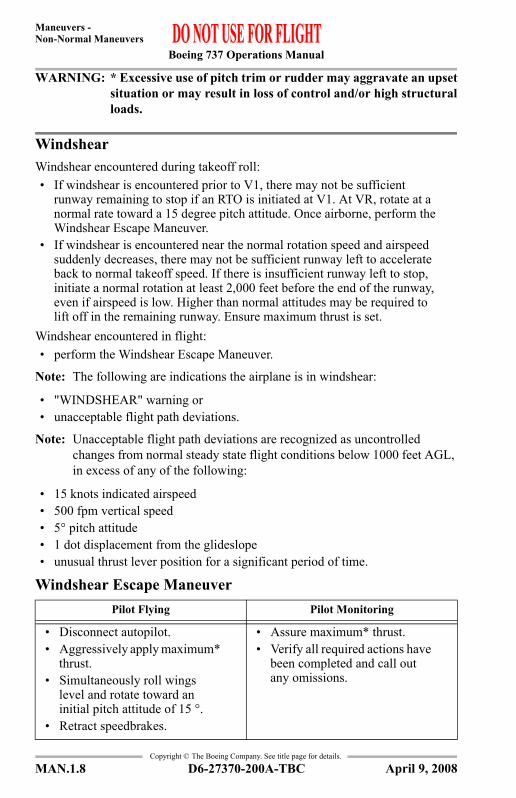
Boeing 737 Operations Manual
Maneuvers -Non-Normal Maneuvers
Copyright © The Boeing Company. See title page for details.
WARNING: * Excessive use of pitch trim or rudder may aggravate an upsetsituation or may result in loss of control and/or high structuralloads.
WindshearWindshear encountered during takeoff roll:• If windshear is encountered prior to V1, there may not be sufficient
runway remaining to stop if an RTO is initiated at V1. At VR, rotate at a normal rate toward a 15 degree pitch attitude. Once airborne, perform the Windshear Escape Maneuver.
• If windshear is encountered near the normal rotation speed and airspeed suddenly decreases, there may not be sufficient runway left to accelerate back to normal takeoff speed. If there is insufficient runway left to stop, initiate a normal rotation at least 2,000 feet before the end of the runway, even if airspeed is low. Higher than normal attitudes may be required to lift off in the remaining runway. Ensure maximum thrust is set.
Windshear encountered in flight:• perform the Windshear Escape Maneuver.
Note: The following are indications the airplane is in windshear:
• "WINDSHEAR" warning or • unacceptable flight path deviations.
Note: Unacceptable flight path deviations are recognized as uncontrolled changes from normal steady state flight conditions below 1000 feet AGL, in excess of any of the following:
• 15 knots indicated airspeed• 500 fpm vertical speed• 5° pitch attitude• 1 dot displacement from the glideslope• unusual thrust lever position for a significant period of time.
Windshear Escape ManeuverPilot Flying Pilot Monitoring
• Disconnect autopilot.• Aggressively apply maximum*
thrust.• Simultaneously roll wings
level and rotate toward an initial pitch attitude of 15 °.
• Retract speedbrakes.
• Assure maximum* thrust.• Verify all required actions have
been completed and call out any omissions.
MAN.1.8 D6-27370-200A-TBC April 9, 2008

Boeing 737 Operations Manual
Maneuvers -Non-Normal Maneuvers
Copyright © The Boeing Company. See title page for details.
Note: Aft control column force increases as the airspeed decreases. In all cases, the pitch attitude that results in intermittent stick shaker or initial buffet is the upper pitch attitude limit. Flight at intermittent stick shaker may be required to obtain a positive terrain separation. Smooth, steady control will avoid a pitch attitude overshoot and stall.
Note: *Maximum thrust can be obtained by advancing the thrust levers to the takeoff or go-around limit. If terrain contact is imminent, advance thrust levers full forward.
• Do not change flap or gear configuration until windshear is no longer a factor.
• Monitor vertical speed and altitude.
• Do not attempt to regain lost airspeed until windshear is no longer a factor.
• Monitor vertical speed and altitude.
• Call out any trend toward terrain contact, descending flight path, or significant airspeed changes.
Pilot Flying Pilot Monitoring
D6-27370-200A-TBC MAN.1.9April 9, 2008

Boeing 737 Operations Manual
Maneuvers -Non-Normal Maneuvers
Copyright © The Boeing Company. See title page for details.
IntentionallyBlank
MAN.1.10 D6-27370-200A-TBC April 9, 2008

Boeing 737 Operations Manual
Maneuvers Chapter MANFlight Patterns Section 2
Copyright © The Boeing Company. See title page for details.
MAN.2 Maneuvers-Flight PatternsTakeoff
Acc
eler
atio
n he
ight
• S
et fl
aps u
p m
aneu
verin
g
spe
ed •
Ret
ract
flap
s on
sche
dule
Enga
ge th
e au
topi
lot a
fter f
laps
are
up.
Flap
s up
• S
et n
orm
al c
limb
spee
d
(2
engi
ne)
• M
aint
ain
flaps
up
m
aneu
verin
g sp
eed
(
1 en
gine
) •
Sel
ect C
ON
thru
st (1
eng
ine)
• D
o th
e N
NC
(as n
eede
d) •
Do
the
Afte
r Tak
eoff
c
heck
list
Posi
tive
rate
of c
limb
• R
etra
ct g
ear
Thr
ust r
educ
tion
heig
ht •
Clim
b th
rust
(2
engi
ne)
Initi
al c
limb
spee
d •
V2+
15 to
V2+
25 k
nots
, or
V
2 to
V2+
20 k
nots
(1 e
ngin
e)
Thr
ust s
et •
Man
ually
adv
ance
thr
ust t
o st
abili
ze •
Man
ually
adv
ance
thr
ust t
o ta
keof
f EPR
VR
• R
otat
eV
1
Take
off r
oll
• T
akeo
ff th
rust
by
60 k
nots
• M
onito
r airs
peed
• M
aint
ain
light
forw
ard
p
ress
ure
For a
n im
med
iate
turn
afte
rta
keof
f, m
aint
ain
V2
+ 15
with
take
off f
laps
whi
lem
aneu
verin
g.
Not
e:
D6-27370-200A-TBC MAN.2.1October 7, 2005

Boeing 737 Operations Manual
Maneuvers -Flight Patterns
Copyright © The Boeing Company. See title page for details.
ILS Approach
Min
imum
Sin
gle
Cha
nnel
Aut
opilo
t Use
Alti
tude
(see
lim
itatio
ns c
hapt
er)
• D
isen
gage
A/P
On
RA
DA
R v
ecto
rs •
HD
G S
EL •
Pitc
h m
ode
(as n
eede
d)
Enr
oute
to fi
x •
Rol
l mod
e (a
s nee
ded)
• P
itch
mod
e (a
s nee
ded)
Glid
e sl
ope
inte
rcep
t •
Lan
ding
flap
s (2
engi
ne)
• S
et m
isse
d ap
proa
ch a
ltitu
de •
Do
the
Land
ing
chec
klis
t
Fix
(LO
M, M
KR
, DM
E) •
Ver
ify c
ross
ing
altit
ude
Glid
e sl
ope
aliv
e •
Gea
r dow
n •
Fla
ps 1
5 (f
inal
fla
p fo
r 1 e
ngin
e) •
Arm
spee
dbra
ke
• Fla
ps 1
• Fla
ps 5
Loc
aliz
er c
aptu
re •
Fin
al a
ppro
ach
c
ours
e he
adin
g
Inte
rcep
t hea
ding
• IL
S tu
ned
and
i
dent
ified
• L
OC
and
G/S
poi
nter
s
sho
wn
• S
elec
t AU
TO A
PP
App
roac
hing
inte
rcep
t hea
ding
• F
laps
5
MAN.2.2 D6-27370-200A-TBC October 7, 2005

Boeing 737 Operations Manual
Maneuvers -Flight Patterns
Copyright © The Boeing Company. See title page for details.
Non-ILS Instrument ApproachesO
n R
AD
AR
vec
tors
App
roac
hing
inte
rcep
t hea
ding
• F
laps
5
• Fla
ps 5
• Fla
ps 1
FAF
• H
DG
SEL
• P
itch
mod
e (a
s nee
ded)
Enr
oute
to fi
x •
Rol
l mod
e (a
s nee
ded)
• P
itch
mod
e (a
s nee
ded)
App
roac
hing
300
feet
abo
ve M
DA
(H)
• S
et m
isse
d ap
proa
ch a
ltitu
de
Des
cend
to M
DA
(H)
• L
andi
ng fl
aps (
2 en
gine
s) •
Use
CW
S pi
tch
mod
e (S
P-77
) •
Set
V/S
(SP-
177)
• D
o th
e La
ndin
g ch
eckl
is
At M
DA
(H)
• In
terc
ept l
andi
ng p
rofil
e
and
dis
enga
ge a
utop
ilot
a
nd a
utot
hrot
tle
Inte
rcep
t Hea
ding
• R
oll m
ode
(as n
eede
d)
Inbo
und
(App
roxi
mat
ely
2 N
M)
• G
ear d
own
• F
laps
15
(land
ing
flaps
1 e
ngin
e) •
Arm
spee
dbra
ke •
Set
MD
A(H
)
D6-27370-200A-TBC MAN.2.3April 7, 2006

Boeing 737 Operations Manual
Maneuvers -Flight Patterns
Copyright © The Boeing Company. See title page for details.
Circling Approach
MC
P al
titud
e / M
DA
(H)
• S
elec
t ALT
HO
LD
(as
nee
ded)
• S
et m
isse
d ap
proa
ch a
ltitu
de •
Sel
ect H
DG
SEL
or C
WS
r
oll m
ode
If a
mis
sed
appr
oach
is n
eede
d at
any
time
whi
le c
irclin
g, m
ake
anin
itial
clim
bing
turn
tow
ard
the
land
ing
runw
ay a
nd in
terc
ept t
hem
isse
d ap
proa
ch c
ours
e.
Con
figur
atio
n at
MD
A(H
) •
Gea
r dow
n •
Gea
r up
(1 e
ngin
e) •
Fla
ps 1
5 •
Fla
ps 1
0 (1
eng
ine)
• A
rm sp
eedb
rake
Inte
rcep
ting
land
ing
prof
ile •
Dis
enga
ge a
utop
ilot a
nd
a
utot
hrot
tle (S
P-17
7) •
Dis
enga
ge a
utop
ilot (
SP-7
7)
Bef
ore
turn
ing
base
or
initi
atin
g th
e tu
rn to
bas
e •
Gea
r dow
n (1
eng
ine)
• L
andi
ng fl
aps
• D
o th
e La
ndin
g ch
eckl
ist
MAN.2.4 D6-27370-200A-TBC October 7, 2005

Boeing 737 Operations Manual
Maneuvers -Flight Patterns
Copyright © The Boeing Company. See title page for details.
Visual Traffic Pattern
1500
FT 2
NM
2 -2
1/2
NM
Ent
erin
g do
wnw
ind
• F
laps
5
700
- 500
feet
• S
tabi
lized
on
prof
ile
Bef
ore
turn
ing
base
or
• G
ear d
own
• F
laps
15
(land
ing
flaps
f
or 1
eng
ine)
• A
rm sp
eedb
rake
• S
tart
desc
ent a
s nee
ded
Bas
e •
Lan
ding
flap
s
(2
engi
ne)
• D
o th
e La
ndin
g
che
cklis
t
initi
atin
g th
e tu
rn to
bas
e
D6-27370-200A-TBC MAN.2.5April 3, 2007

Boeing 737 Operations Manual
Maneuvers -Flight Patterns
Copyright © The Boeing Company. See title page for details.
Go–Around and Missed Approach
Aft
er p
lann
ed fl
aps s
et a
nd a
t or
Acc
eler
atio
n he
ight
• S
et sp
eed
for p
lann
ed fl
ap
set
ting
(1 e
ngin
e) (S
P-17
7) •
Ret
ract
flap
s on
sche
dule
abov
e fla
p m
aneu
veri
ng sp
eed
• S
elec
t LV
L C
HG
(as i
nsta
lled)
o
r pitc
h m
ode
(as n
eede
d) •
Ver
ify c
limb
thru
st
(C
ON
thru
st, 1
eng
ine)
• V
erify
alti
tude
cap
ture
• D
o th
e A
fter T
akeo
ff ch
eckl
ist
Abo
ve 4
00 fe
et R
A •
Sel
ect r
oll m
ode
• T
une
radi
os (a
s nee
ded)
• V
erify
mis
sed
appr
oach
a
ltitu
de se
t •
Ver
ify ro
ute
track
ing
Initi
atio
n •
Pus
h G
A (S
P-77
) or T
O/G
A (S
P-17
7),
f
laps
15
(fla
ps 1
, 1 e
ngin
e) •
Dis
enga
ge th
e au
topi
lot (
SP-7
7) •
If th
e ai
rpla
ne is
not
equ
ippe
d w
ith a
n
aut
othr
ottle
, set
go-
arou
nd th
rust
• E
stab
lish
go-a
roun
d at
titud
e (S
P-77
) •
Ver
ify g
o-ar
ound
atti
tude
(SP-
177)
• V
erify
or a
djus
t thr
ust a
s nee
ded
• P
ositi
ve ra
te o
f clim
b - g
ear u
p
For a
man
ual g
o-ar
ound
: •
rota
te m
anua
lly •
set g
o-ar
ound
thru
st •
eng
age
auto
pilo
t as n
eede
d
MAN.2.6 D6-27370-200A-TBC October 7, 2005
Boeing 737 Operations Manual
Performance Inflight Chapter PITable of Contents Section 0
Copyright © The Boeing Company. See title page for details.
PI.0 Performance Inflight-Table of Contents737-200ADV JT8D-15A LB FAA
General . . . . . . . . . . . . . . . . . . . . . . . . . . . . . . . . . . . . . . . . . . . . PI.10.1
Takeoff Speeds . . . . . . . . . . . . . . . . . . . . . . . . . . . . . . . . . . . PI.10.1VMCG . . . . . . . . . . . . . . . . . . . . . . . . . . . . . . . . . . . . . . . . . PI.10.2Clearway and Stopway V1 Adjustments . . . . . . . . . . . . . . . PI.10.2Stab Trim Setting . . . . . . . . . . . . . . . . . . . . . . . . . . . . . . . . . PI.10.2VREF (KIAS) . . . . . . . . . . . . . . . . . . . . . . . . . . . . . . . . . . . . PI.10.2Flap Maneuver Speeds . . . . . . . . . . . . . . . . . . . . . . . . . . . . . PI.10.3Slush/Standing Water Takeoff . . . . . . . . . . . . . . . . . . . . . . . PI.10.4Slippery Runway Takeoff . . . . . . . . . . . . . . . . . . . . . . . . . . . PI.10.6Takeoff EPR . . . . . . . . . . . . . . . . . . . . . . . . . . . . . . . . . . . . . PI.10.8%N1 vs EPR Crosscheck . . . . . . . . . . . . . . . . . . . . . . . . . . . PI.10.8Reduced Takeoff EPR . . . . . . . . . . . . . . . . . . . . . . . . . . . . . . PI.10.9Max Climb EPR . . . . . . . . . . . . . . . . . . . . . . . . . . . . . . . . . PI.10.12Go-around EPR . . . . . . . . . . . . . . . . . . . . . . . . . . . . . . . . . . PI.10.13Flight With Unreliable Airspeed / Turbulent Air Penetration . . . . . . . . . . . . . . . . . . . . . . . . . PI.10.14
All Engines . . . . . . . . . . . . . . . . . . . . . . . . . . . . . . . . . . . . . . . . . . PI.11.1Long Range Cruise Maximum Operating Altitude . . . . . . . PI.11.1Long Range Cruise Control . . . . . . . . . . . . . . . . . . . . . . . . . PI.11.2Long Range Cruise Enroute Fuel and Time - Low Altitudes . . . . . . . . . . . . . . . . . . . . . . . . . . . . . . . . . . . . . . . . PI.11.3Long Range Cruise Enroute Fuel and Time - High Altitudes . . . . . . . . . . . . . . . . . . . . . . . . . . . . . . . . . . . . . . . . PI.11.4Long Range Cruise Wind-Altitude Trade . . . . . . . . . . . . . . . PI.11.5Descent at .70/280/250 . . . . . . . . . . . . . . . . . . . . . . . . . . . . . PI.11.5Holding . . . . . . . . . . . . . . . . . . . . . . . . . . . . . . . . . . . . . . . . . PI.11.6
Advisory Information . . . . . . . . . . . . . . . . . . . . . . . . . . . . . . . . . PI.12.1Normal Configuration Landing Distance - Autobrake System . . . . . . . . . . . . . . . . . . . . . . . . . . . . . . . . . . . . . . . . . PI.12.1Normal Configuration Landing Distance - Digital Autobrake System . . . . . . . . . . . . . . . . . . . . . . . . . . . . . . . . PI.12.4
D6-27370-200A-TBC PI.TOC.0.1October 9, 2007

Boeing 737 Operations Manual
Performance Inflight -Table of Contents
Copyright © The Boeing Company. See title page for details.
Non-Normal Configuration Landing Distance . . . . . . . . . . . PI.12.7Brake Cooling Schedule . . . . . . . . . . . . . . . . . . . . . . . . . . . PI.12.11
Engine Inoperative . . . . . . . . . . . . . . . . . . . . . . . . . . . . . . . . . . . PI.13.1Max Continuous EPR . . . . . . . . . . . . . . . . . . . . . . . . . . . . . . PI.13.1Driftdown Speed/Level Off Altitude . . . . . . . . . . . . . . . . . . . PI.13.2Driftdown/LRC Cruise Range Capability . . . . . . . . . . . . . . . PI.13.2Long Range Cruise Altitude Capability . . . . . . . . . . . . . . . . PI.13.3Long Range Cruise Control . . . . . . . . . . . . . . . . . . . . . . . . . PI.13.3Long Range Cruise Diversion Fuel and Time . . . . . . . . . . . . PI.13.4Holding . . . . . . . . . . . . . . . . . . . . . . . . . . . . . . . . . . . . . . . . . PI.13.5
Gear Down . . . . . . . . . . . . . . . . . . . . . . . . . . . . . . . . . . . . . . . . . . PI.14.1220 KIAS Cruise Altitude Capability . . . . . . . . . . . . . . . . . . PI.14.1220 KIAS Cruise Control . . . . . . . . . . . . . . . . . . . . . . . . . . . PI.14.1220 KIAS Enroute Fuel and Time . . . . . . . . . . . . . . . . . . . . . PI.14.2Descent at 220 KIAS . . . . . . . . . . . . . . . . . . . . . . . . . . . . . . . PI.14.2Holding . . . . . . . . . . . . . . . . . . . . . . . . . . . . . . . . . . . . . . . . . PI.14.3
Text . . . . . . . . . . . . . . . . . . . . . . . . . . . . . . . . . . . . . . . . . . . . . . . . PI.15.1Introduction . . . . . . . . . . . . . . . . . . . . . . . . . . . . . . . . . . . . . . PI.15.1General . . . . . . . . . . . . . . . . . . . . . . . . . . . . . . . . . . . . . . . . . PI.15.1All Engines . . . . . . . . . . . . . . . . . . . . . . . . . . . . . . . . . . . . . . PI.15.5Advisory Information . . . . . . . . . . . . . . . . . . . . . . . . . . . . . . PI.15.7Engine Inoperative . . . . . . . . . . . . . . . . . . . . . . . . . . . . . . . . PI.15.8Gear Down . . . . . . . . . . . . . . . . . . . . . . . . . . . . . . . . . . . . . PI.15.10
737-200ADV JT8D-17A LB FAA
General . . . . . . . . . . . . . . . . . . . . . . . . . . . . . . . . . . . . . . . . . . . . . PI.20.1
Takeoff Speeds . . . . . . . . . . . . . . . . . . . . . . . . . . . . . . . . . . . PI.20.1VMCG . . . . . . . . . . . . . . . . . . . . . . . . . . . . . . . . . . . . . . . . . . PI.20.2Clearway and Stopway V1 Adjustments . . . . . . . . . . . . . . . PI.20.2Stab Trim Setting . . . . . . . . . . . . . . . . . . . . . . . . . . . . . . . . . . PI.20.2VREF (KIAS) . . . . . . . . . . . . . . . . . . . . . . . . . . . . . . . . . . . . PI.20.2Flap Maneuver Speeds . . . . . . . . . . . . . . . . . . . . . . . . . . . . . PI.20.3Slush/Standing Water Takeoff . . . . . . . . . . . . . . . . . . . . . . . . PI.20.4
PI.TOC.0.2 D6-27370-200A-TBC October 9, 2007

Boeing 737 Operations Manual
Performance Inflight -Table of Contents
Copyright © The Boeing Company. See title page for details.
Takeoff EPR . . . . . . . . . . . . . . . . . . . . . . . . . . . . . . . . . . . . . PI.20.5%N1 vs EPR Crosscheck . . . . . . . . . . . . . . . . . . . . . . . . . . . PI.20.5Reduced Takeoff EPR . . . . . . . . . . . . . . . . . . . . . . . . . . . . . . PI.20.6Max Climb EPR . . . . . . . . . . . . . . . . . . . . . . . . . . . . . . . . . . PI.20.9Go-around EPR . . . . . . . . . . . . . . . . . . . . . . . . . . . . . . . . . . PI.20.10Flight With Unreliable Airspeed / Turbulent Air Penetration . . . . . . . . . . . . . . . . . . . . . . . . . PI.20.11
All Engines . . . . . . . . . . . . . . . . . . . . . . . . . . . . . . . . . . . . . . . . . PI.21.1Long Range Cruise Maximum Operating Altitude . . . . . . . PI.21.1Long Range Cruise Control . . . . . . . . . . . . . . . . . . . . . . . . . PI.21.2Long Range Cruise Enroute Fuel and Time - Low Altitudes . . . . . . . . . . . . . . . . . . . . . . . . . . . . . . . . . . . . . . . . PI.21.3Long Range Cruise Enroute Fuel and Time - High Altitudes . . . . . . . . . . . . . . . . . . . . . . . . . . . . . . . . . . . . . . . . PI.21.4Long Range Cruise Wind-Altitude Trade . . . . . . . . . . . . . . . PI.21.5Descent at .70/280/250 . . . . . . . . . . . . . . . . . . . . . . . . . . . . . PI.21.5Holding . . . . . . . . . . . . . . . . . . . . . . . . . . . . . . . . . . . . . . . . . PI.21.6
Advisory Information . . . . . . . . . . . . . . . . . . . . . . . . . . . . . . . . . PI.22.1Normal Configuration Landing Distance - Autobrake System . . . . . . . . . . . . . . . . . . . . . . . . . . . . . . . . . . . . . . . . . PI.22.1Normal Configuration Landing Distance - Digital Autobrake System . . . . . . . . . . . . . . . . . . . . . . . . . . . . . . . . PI.22.4Non-Normal Configuration Landing Distance . . . . . . . . . . . PI.22.7Brake Cooling Schedule . . . . . . . . . . . . . . . . . . . . . . . . . . . PI.22.11
Engine Inoperative . . . . . . . . . . . . . . . . . . . . . . . . . . . . . . . . . . . PI.23.1Max Continuous EPR . . . . . . . . . . . . . . . . . . . . . . . . . . . . . . PI.23.1Driftdown Speed/Level Off Altitude . . . . . . . . . . . . . . . . . . PI.23.2Driftdown/LRC Cruise Range Capability . . . . . . . . . . . . . . PI.23.2Long Range Cruise Altitude Capability . . . . . . . . . . . . . . . . PI.23.3Long Range Cruise Control . . . . . . . . . . . . . . . . . . . . . . . . . PI.23.3Long Range Cruise Diversion Fuel and Time . . . . . . . . . . . PI.23.4Holding . . . . . . . . . . . . . . . . . . . . . . . . . . . . . . . . . . . . . . . . . PI.23.5
Gear Down . . . . . . . . . . . . . . . . . . . . . . . . . . . . . . . . . . . . . . . . . PI.24.1220 KIAS Cruise Altitude Capability . . . . . . . . . . . . . . . . . . PI.24.1220 KIAS Cruise Control . . . . . . . . . . . . . . . . . . . . . . . . . . . PI.24.1
D6-27370-200A-TBC PI.TOC.0.3October 9, 2007

Boeing 737 Operations Manual
Performance Inflight -Table of Contents
Copyright © The Boeing Company. See title page for details.
220 KIAS Enroute Fuel and Time . . . . . . . . . . . . . . . . . . . . . PI.24.2Descent at 220 KIAS . . . . . . . . . . . . . . . . . . . . . . . . . . . . . . . PI.24.2Holding . . . . . . . . . . . . . . . . . . . . . . . . . . . . . . . . . . . . . . . . . PI.24.3
Text . . . . . . . . . . . . . . . . . . . . . . . . . . . . . . . . . . . . . . . . . . . . . . . . PI.25.1Introduction . . . . . . . . . . . . . . . . . . . . . . . . . . . . . . . . . . . . . . PI.25.1General . . . . . . . . . . . . . . . . . . . . . . . . . . . . . . . . . . . . . . . . . PI.25.1All Engines . . . . . . . . . . . . . . . . . . . . . . . . . . . . . . . . . . . . . . PI.25.5Advisory Information . . . . . . . . . . . . . . . . . . . . . . . . . . . . . . PI.25.6Engine Inoperative . . . . . . . . . . . . . . . . . . . . . . . . . . . . . . . . PI.25.8Gear Down . . . . . . . . . . . . . . . . . . . . . . . . . . . . . . . . . . . . . . PI.25.9
737-200ADV JT8D-9 LB FAA
General . . . . . . . . . . . . . . . . . . . . . . . . . . . . . . . . . . . . . . . . . . . . . PI.30.1
Takeoff Speeds . . . . . . . . . . . . . . . . . . . . . . . . . . . . . . . . . . . PI.30.1VMCG . . . . . . . . . . . . . . . . . . . . . . . . . . . . . . . . . . . . . . . . . . PI.30.2Clearway and Stopway V1 Adjustments . . . . . . . . . . . . . . . PI.30.2Stab Trim Setting . . . . . . . . . . . . . . . . . . . . . . . . . . . . . . . . . . PI.30.2VREF (KIAS) . . . . . . . . . . . . . . . . . . . . . . . . . . . . . . . . . . . . PI.30.2Flap Maneuver Speeds . . . . . . . . . . . . . . . . . . . . . . . . . . . . . PI.30.3Slush/Standing Water Takeoff . . . . . . . . . . . . . . . . . . . . . . . . PI.30.4Takeoff EPR . . . . . . . . . . . . . . . . . . . . . . . . . . . . . . . . . . . . . PI.30.5%N1 vs EPR Crosscheck . . . . . . . . . . . . . . . . . . . . . . . . . . . PI.30.5Reduced Takeoff EPR . . . . . . . . . . . . . . . . . . . . . . . . . . . . . . PI.30.6Max Climb EPR . . . . . . . . . . . . . . . . . . . . . . . . . . . . . . . . . . PI.30.8Go-around EPR . . . . . . . . . . . . . . . . . . . . . . . . . . . . . . . . . . . PI.30.9Flight With Unreliable Airspeed / Turbulent Air Penetration . . . . . . . . . . . . . . . . . . . . . . . . . . PI.30.10
All Engines . . . . . . . . . . . . . . . . . . . . . . . . . . . . . . . . . . . . . . . . . . PI.31.1Long Range Cruise Maximum Operating Altitude . . . . . . . PI.31.1Long Range Cruise Control . . . . . . . . . . . . . . . . . . . . . . . . . PI.31.2Long Range Cruise Enroute Fuel and Time - Low Altitudes . . . . . . . . . . . . . . . . . . . . . . . . . . . . . . . . . . . . . . . . PI.31.3Long Range Cruise Enroute Fuel and Time - High Altitudes . . . . . . . . . . . . . . . . . . . . . . . . . . . . . . . . . . . . . . . . PI.31.4
PI.TOC.0.4 D6-27370-200A-TBC October 9, 2007

Boeing 737 Operations Manual
Performance Inflight -Table of Contents
Copyright © The Boeing Company. See title page for details.
Long Range Cruise Wind-Altitude Trade . . . . . . . . . . . . . . . PI.31.5Descent at .70/280/250 . . . . . . . . . . . . . . . . . . . . . . . . . . . . . PI.31.5Holding . . . . . . . . . . . . . . . . . . . . . . . . . . . . . . . . . . . . . . . . . PI.31.6
Advisory Information . . . . . . . . . . . . . . . . . . . . . . . . . . . . . . . . . PI.32.1Normal Configuration Landing Distance - Autobrake System . . . . . . . . . . . . . . . . . . . . . . . . . . . . . . . . . . . . . . . . . PI.32.1Normal Configuration Landing Distance - Digital Autobrake System . . . . . . . . . . . . . . . . . . . . . . . . . . . . . . . . PI.32.4Non-Normal Configuration Landing Distance . . . . . . . . . . . PI.32.7Brake Cooling Schedule . . . . . . . . . . . . . . . . . . . . . . . . . . . PI.32.11
Engine Inoperative . . . . . . . . . . . . . . . . . . . . . . . . . . . . . . . . . . . PI.33.1Max Continuous EPR . . . . . . . . . . . . . . . . . . . . . . . . . . . . . . PI.33.1Driftdown Speed/Level Off Altitude . . . . . . . . . . . . . . . . . . PI.33.2Driftdown/LRC Cruise Range Capability . . . . . . . . . . . . . . PI.33.2Long Range Cruise Altitude Capability . . . . . . . . . . . . . . . . PI.33.3Long Range Cruise Control . . . . . . . . . . . . . . . . . . . . . . . . . PI.33.3Long Range Cruise Diversion Fuel and Time . . . . . . . . . . . PI.33.4Holding . . . . . . . . . . . . . . . . . . . . . . . . . . . . . . . . . . . . . . . . . PI.33.5
Gear Down . . . . . . . . . . . . . . . . . . . . . . . . . . . . . . . . . . . . . . . . . PI.34.1220 KIAS Cruise Altitude Capability . . . . . . . . . . . . . . . . . . PI.34.1220 KIAS Cruise Control . . . . . . . . . . . . . . . . . . . . . . . . . . . PI.34.2220 KIAS Enroute Fuel and Time . . . . . . . . . . . . . . . . . . . . PI.34.3Descent at 220 KIAS . . . . . . . . . . . . . . . . . . . . . . . . . . . . . . PI.34.3Holding . . . . . . . . . . . . . . . . . . . . . . . . . . . . . . . . . . . . . . . . . PI.34.4
Text . . . . . . . . . . . . . . . . . . . . . . . . . . . . . . . . . . . . . . . . . . . . . . . . PI.35.1Introduction . . . . . . . . . . . . . . . . . . . . . . . . . . . . . . . . . . . . . PI.35.1General . . . . . . . . . . . . . . . . . . . . . . . . . . . . . . . . . . . . . . . . . PI.35.1All Engines . . . . . . . . . . . . . . . . . . . . . . . . . . . . . . . . . . . . . . PI.35.5Advisory Information . . . . . . . . . . . . . . . . . . . . . . . . . . . . . . PI.35.6Engine Inoperative . . . . . . . . . . . . . . . . . . . . . . . . . . . . . . . . PI.35.8Gear Down . . . . . . . . . . . . . . . . . . . . . . . . . . . . . . . . . . . . . . PI.35.9
D6-27370-200A-TBC PI.TOC.0.5October 9, 2007

Boeing 737 Operations Manual
Performance Inflight -Table of Contents
Copyright © The Boeing Company. See title page for details.
IntentionallyBlank
PI.TOC.0.6 D6-27370-200A-TBC October 9, 2007

Boeing 737 Operations Manual
Performance Inflight - Chapter PIGeneral Section 10
737-200ADV/JT8D-15A
FAST
-Doc
PI/P
D T
empl
ate
9/1/
99
Copyright © The Boeing Company. See title page for details.
PI.10 Performance Inflight --GeneralGeneral
Takeoff Speeds
BOXED AREA INDICATES PERFORMANCE AFFECTED BY MINIMUM CONTROL SPEED,
110
ANTI-SKID ON
70 80 90100
70 80 90100110
110
120
70 80 90100110
70 80 90
130
100
120
70 80 90
130
100110120
70 80 90
130
100110120
WT1000 LB
131127126131126125131126125
122
110111
110113121
110117124
114122129136
116124132139
120
105106
105108116
105112119
108117125133
110119127135
114
105105
105107115
105111118
108116124132
110118126134
114
110111118
110113121127134110117124131
114122129136143
116124132139146
120
105106113
105108116123131105111119126
108116124132140
110119127135143
114
105105112
105107115122130105110118125
108115123131138
110118126134141
114
110110118125
110113121127134110117124131138146114122129136143
116124132139146153
120
105105113121
105107115123130105111119126134142
113122
107116124132139
109118126135142150
105105112120
105106114122129105110118125133141107115123131137
109117125134140147
113
110110118125
110113121127134110117124131138146114122129136143150
116
105105112120
105107115122130105110118126133141106115123131139146
108
105105111119
105106114121129105109117125132140106114122130137144
108
110110118125
110113121127134110117124131138146114122129136143150156116
105105112120
105105114122129105110118125133141106115123131138145152107
149
105105111119
105105113121128105109117124132140105114122130136143
107
110110118125
110113121127134110117124131138146114122129136143150156116
132
105105111119
105105113121128105108117124
140105114122130138145152107
105105110118
105105112120127105107116123131139105113121129135143149106
- 1 32
94 107- 4 9
TO
TO
TO
TO
TO
TO
TO
TO
TO
TO
TO
TO
TO
TO
TO
TO
TO
TO
TO
TO
TO
TO
TO
TO
TO
126117
125
142140149146
116
134133
124132139146153145
117116
134133125
141148155
124
139
152
124132139146153160
116125133141148155
115124132139145152
124132139146153160
122 123136132131144140138
128123136132131144140
145138
147
128
151
131130
145
121
139138147
128136144151145
113113122121
139138147154151
130129
120128136144151158
121120130129138137146144
120128136144151158
111
153
111
150
120128136144151158165
129
111120
137145153160
111119128136143150157
151148146158155152158155152
165161158165161158
33 85
39 44102 112
1 29
41 48106 120 31 38 87 101 3 29 37 85-18 0
50 55122 131 42 52108 126 33 40 93 105
-14 2 6 36-54 -19
-54 -5
-65 -2
34 41
10 32 50 92- 9 5 15 42-54 -15-65 5
35 43 94 110 23 33 72 93
24 49-54 -10-65 14
-54 34-65 93-54 22-65 71
-65 23
9 TO 10
-1 TO 1
1 TO 3
3 TO 5
5 TO 7
7 TO 9
V1, VR, V2
25
30 39 86 103
6 30 43 86
44 49111 121
VV 2R1VVV 2R1VVV 2R1VVV 2R1VVV 2R1VVV 2R1V
15
10
5
2
1
OAT
°C°F°C°F°C°F°C°F°C°F°C°F
1000 FTALTITUDEPRESSURE
1% DOWN SLOPESUBTRACT 1 KT PER
5 KTS TAILWINDSUBTRACT 1 KT PER
SLOPEWIND
V1 ADJUSTMENTSREDUCE V1 AND VR BY 1 KNOT AND
FLAPS
V2 BY 2 KNOTS WITH 15% FWD C.G.LIMIT.
MINIMUM FIELD LENGTH FOR LIGHTEST WEIGHT ABOVE BOXED AREA IS REQUIRED.
D6-27370-200A-TBC PI.10.1April 7, 2000

Boeing 737 Operations Manual
Performance Inflight -General
737-200ADV/JT8D-15A
Copyright © The Boeing Company. See title page for details.
General
VMCG
Clearway and Stopway V1 Adjustments
Maximum Allowable Clearway
Stab Trim SettingMax Takeoff Thrust
VREF (KIAS)
OAT (°C)
PRESSURE ALTITUDE (FT)0 2000 4000 6000 8000 10000
50 95 91 8840 99 95 92 89 8530 103 99 95 92 88 8520 103 101 97 94 90 8710 103 101 97 94 90 870 103 104 99 96 92 89
-10 103 104 101 98 94 90-20 103 104 103 99 96 92-30 103 104 103 99 96 92-40 103 104 103 99 96 92
CLEARWAY MINUS STOPWAY (FT)
NORMAL V1 (KIAS)100 120 140 160
900 -3 -3 -3 -3600 -2 -2 -2 -2300 -1 -1 -1 -10 0 0 0 0
-300 1 1 1 1-600 2 2 2 2-900 3 3 3 3
FIELD LENGTH (FT)
MAX ALLOWABLE CLEARWAY FOR V1
REDUCTION (FT)4000 4506000 6008000 70010000 800
C.G. %MAC 6 10 14 18 22 26 30 32FLAPS 1 THRU FLAPS 10 7 3/4 7 6 1/4 5 1/2 4 3/4 4 3 1/4 2 3/4
FLAPS 15 & FLAPS 25 8 3/4 7 3/4 7 6 5 4 3 1/4 2 3/4
WEIGHT (1000 LB)
FLAPS40 30 15
130 149 154 161125 146 150 158120 142 146 154115 139 142 150110 135 139 146105 132 135 142100 128 131 13895 124 127 13490 121 124 13185 117 120 12780 113 116 12375 110 112 11970 106 109 115
For approach speed add wind factor of 1/2 headwind component + gust (max 20 knots).
PI.10.2 D6-27370-200A-TBC April 7, 2000

Boeing 737 Operations Manual
Performance Inflight -General
737-200ADV/JT8D-15A
Copyright © The Boeing Company. See title page for details.
General
Flap Maneuver Speeds
FLAP POSITION
MANEUVER SPEED (KIAS)WEIGHT
AT OR BELOW 117000 LB ABOVE 117000 LB AND AT OR BELOW 138500 LB ABOVE 138500 LB
UP 210 220 2301 190 200 2105 170 180 190
10 160 170 18015 150 160 17025 140 150 160
D6-27370-200A-TBC PI.10.3April 7, 2000
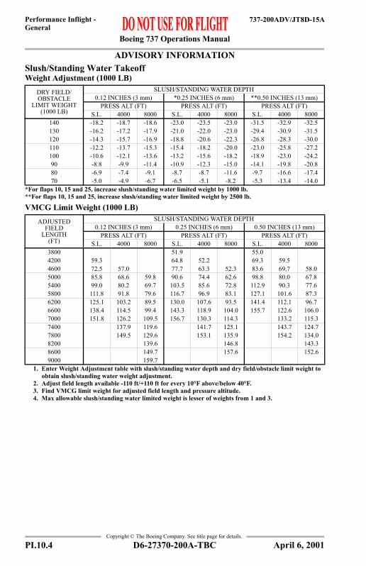
Boeing 737 Operations Manual
Performance Inflight -General
737-200ADV/JT8D-15A
Copyright © The Boeing Company. See title page for details.
ADVISORY INFORMATIONSlush/Standing Water TakeoffWeight Adjustment (1000 LB)
VMCG Limit Weight (1000 LB)
DRY FIELD/OBSTACLE
LIMIT WEIGHT (1000 LB)
SLUSH/STANDING WATER DEPTH0.12 INCHES (3 mm) *0.25 INCHES (6 mm) **0.50 INCHES (13 mm)
PRESS ALT (FT) PRESS ALT (FT) PRESS ALT (FT)S.L. 4000 8000 S.L. 4000 8000 S.L. 4000 8000
140 -18.2 -18.7 -18.6 -23.0 -23.5 -23.0 -31.5 -32.9 -32.5130 -16.2 -17.2 -17.9 -21.0 -22.0 -23.0 -29.4 -30.9 -31.5120 -14.3 -15.7 -16.9 -18.8 -20.6 -22.3 -26.8 -28.3 -30.0110 -12.2 -13.7 -15.3 -15.4 -18.2 -20.0 -23.0 -25.8 -27.2100 -10.6 -12.1 -13.6 -13.2 -15.6 -18.2 -18.9 -23.0 -24.290 -8.8 -9.9 -11.4 -10.9 -12.3 -15.0 -14.1 -19.8 -20.880 -6.9 -7.4 -9.1 -8.7 -8.7 -11.6 -9.7 -16.6 -17.470 -5.0 -4.9 -6.7 -6.5 -5.1 -8.2 -5.3 -13.4 -14.0
*For flaps 10, 15 and 25, increase slush/standing water limited weight by 1000 lb.**For flaps 10, 15 and 25, increase slush/standing water limited weight by 2500 lb.
ADJUSTED FIELD
LENGTH (FT)
SLUSH/STANDING WATER DEPTH0.12 INCHES (3 mm) 0.25 INCHES (6 mm) 0.50 INCHES (13 mm)
PRESS ALT (FT) PRESS ALT (FT) PRESS ALT (FT)S.L. 4000 8000 S.L. 4000 8000 S.L. 4000 8000
3800 51.9 55.04200 59.3 64.8 52.2 69.3 59.54600 72.5 57.0 77.7 63.3 52.3 83.6 69.7 58.05000 85.8 68.6 59.8 90.6 74.4 62.6 98.8 80.0 67.85400 99.0 80.2 69.7 103.5 85.6 72.8 112.9 90.3 77.65800 111.8 91.8 79.6 116.7 96.9 83.1 127.1 101.6 87.36200 125.1 103.2 89.5 130.0 107.6 93.5 141.4 112.1 96.76600 138.4 114.5 99.4 143.3 118.9 104.0 155.7 122.6 106.07000 151.8 126.2 109.5 156.7 130.3 114.3 133.2 115.37400 137.9 119.6 141.7 125.1 143.7 124.77800 149.5 129.6 153.1 135.9 154.2 134.08200 139.6 146.8 143.38600 149.7 157.6 152.69000 159.7
1. Enter Weight Adjustment table with slush/standing water depth and dry field/obstacle limit weight to obtain slush/standing water weight adjustment.
2. Adjust field length available -110 ft/+110 ft for every 10°F above/below 40°F.3. Find VMCG limit weight for adjusted field length and pressure altitude.4. Max allowable slush/standing water limited weight is lesser of weights from 1 and 3.
PI.10.4 D6-27370-200A-TBC April 6, 2001

Boeing 737 Operations Manual
Performance Inflight -General
737-200ADV/JT8D-15A
Copyright © The Boeing Company. See title page for details.
ADVISORY INFORMATIONSlush/Standing Water TakeoffV1 Adjustment (KIAS)
WEIGHT (1000 LB)
SLUSH/STANDING WATER DEPTH0.12 INCHES (3 mm) 0.25 INCHES (6 mm) 0.50 INCHES (13 mm)
PRESS ALT (FT) PRESS ALT (FT) PRESS ALT (FT)S.L. 4000 8000 S.L. 4000 8000 S.L. 4000 8000
130 -12 -10 -8 -5 -5 -5 1 1 1120 -14 -12 -9 -6 -5 -4 1 1 1110 -16 -13 -10 -9 -5 -3 1 1 1100 -18 -15 -11 -12 -8 -3 1 1 190 -20 -18 -13 -15 -11 -5 -3 0 180 -22 -20 -15 -18 -14 -8 -9 -2 170 -23 -22 -18 -20 -17 -11 -16 -4 160 -24 -24 -20 -23 -21 -15 -23 -6 1
1. Obtain V1, VR and V2 for the actual weight. 2. If VMCG limited, set V1 = VMCG. If not VMCG limited, enter V1 Adjustment table with the actual
weight to obtain V1 speed adjustment. If adjusted V1 is less than VMCG, set V1 = VMCG.
D6-27370-200A-TBC PI.10.5April 6, 2001

Boeing 737 Operations Manual
Performance Inflight -General
737-200ADV/JT8D-15A
Copyright © The Boeing Company. See title page for details.
ADVISORY INFORMATIONSlippery Runway TakeoffWeight Adjustment (1000 LB)
VMCG Limit Weight (1000 LB)
DRY FIELD/OBSTACLE
LIMIT WEIGHT (1000 LB)
REPORTED BRAKING ACTIONGOOD MEDIUM POOR
PRESS ALT (FT) PRESS ALT (FT) PRESS ALT (FT)S.L. 4000 8000 S.L. 4000 8000 S.L. 4000 8000
140 -0.6 -0.6 -0.6 -7.9 -7.9 -7.9 -14.2 -14.2 -14.2130 -1.4 -1.4 -1.4 -7.9 -7.9 -7.9 -13.5 -13.5 -13.5120 -1.8 -1.8 -1.8 -7.8 -7.8 -7.8 -12.9 -12.9 -12.9110 -2.0 -2.0 -2.0 -7.3 -7.3 -7.3 -12.1 -12.1 -12.1100 -2.0 -2.0 -2.0 -7.0 -7.0 -7.0 -11.2 -11.2 -11.290 -1.5 -1.5 -1.5 -6.5 -6.5 -6.5 -9.8 -9.8 -9.880 -1.5 -1.5 -1.5 -5.5 -5.5 -5.5 -7.9 -7.9 -7.970 -1.5 -1.5 -1.5 -4.5 -4.5 -4.5 -5.6 -5.6 -5.6
ADJUSTED FIELD
LENGTH (FT)
REPORTED BRAKING ACTIONGOOD MEDIUM POOR
PRESS ALT (FT) PRESS ALT (FT) PRESS ALT (FT)S.L. 4000 8000 S.L. 4000 8000 S.L. 4000 8000
3000 52.53400 72.53800 92.6 67.5 54.34200 113.0 87.5 62.5 68.6 50.74600 133.0 108.0 82.5 82.9 65.0 56.75000 153.0 128.0 103.0 98.0 79.3 61.4 67.15400 148.0 123.0 113.1 94.0 75.7 77.5 59.35800 143.0 126.9 109.6 90.0 87.9 69.7 51.56200 140.7 123.4 105.8 98.8 80.0 61.96600 154.5 137.2 120.0 110.2 90.6 72.37000 151.0 133.8 121.9 101.6 82.77400 147.6 134.0 113.1 93.37800 146.3 124.9 104.48200 158.7 137.1 116.08600 149.4 127.99000 140.29400 152.5
1. Enter Weight Adjustment table with reported braking action and dry field/obstacle limit weight to obtain slippery runway weight adjustment.
2. Adjust “Good” field length available by -100 ft/+100 ft for every 10°F above/below 40°F. Adjust “Medium” field length available by -100 ft/+100 ft for every 10°F above/below 40°F. Adjust “Poor” field length available by -120 ft/+120 ft for every 10°F above/below 40°F.
3. Find V1(MCG) limit weight for adjusted field length and pressure altitude.4. Max allowable slippery runway limited weight is lesser of weights from 1 and 3.
PI.10.6 D6-27370-200A-TBC April 6, 2001

Boeing 737 Operations Manual
Performance Inflight -General
737-200ADV/JT8D-15A
Copyright © The Boeing Company. See title page for details.
ADVISORY INFORMATIONSlippery Runway TakeoffV1 Adjustment (KIAS)
WEIGHT (1000 LB)
REPORTED BRAKING ACTIONGOOD MEDIUM POOR
PRESS ALT (FT) PRESS ALT (FT) PRESS ALT (FT)S.L. 4000 8000 S.L. 4000 8000 S.L. 4000 8000
130 -6 -3 1 -14 -11 -8 -24 -20 -16120 -7 -4 -1 -16 -13 -10 -26 -22 -18110 -9 -6 -3 -18 -15 -12 -28 -24 -20100 -10 -7 -4 -20 -17 -14 -30 -26 -2290 -12 -9 -6 -22 -19 -16 -31 -27 -2380 -13 -10 -7 -23 -20 -17 -32 -28 -2470 -14 -11 -8 -25 -22 -19 -33 -29 -2560 -15 -12 -9 -26 -23 -20 -34 -30 -26
1. Obtain V1, VR and V2 for the actual weight. 2. If VMCG limited, set V1 = VMCG. If not VMCG limited, enter V1 Adjustment table with the actual
weight to obtain V1 speed adjustment. If adjusted V1 is less than VMCG, set V1 = VMCG.
D6-27370-200A-TBC PI.10.7April 6, 2001

Boeing 737 Operations Manual
Performance Inflight -General
737-200ADV/JT8D-15A
Copyright © The Boeing Company. See title page for details.
Takeoff EPRBased on engine bleed for packs on and anti-ice on or off
EPR Adjustments for Engine Bleeds
%N1 vs EPR Crosscheck(Takeoff and Go-around)
AIRPORT OAT AIRPORT PRESSURE ALTITUDE (FT)
°F °C -1000 0 1000 2000 3000 3856 & ABOVE
130 55 1.84 1.84 1.84 1.84 1.84 1.84122 50 1.90 1.90 1.90 1.90 1.90 1.90113 45 1.94 1.94 1.94 1.94 1.94 1.94104 40 1.99 1.99 1.99 1.99 1.99 1.9995 35 2.04 2.04 2.04 2.04 2.04 2.0486 30 2.05 2.09 2.09 2.09 2.09 2.0977 25 2.05 2.10 2.13 2.12 2.12 2.1268 20 2.05 2.10 2.13 2.14 2.14 2.1459 15 2.05 2.10 2.13 2.14 2.14 2.1450 10 2.05 2.10 2.14 2.14 2.14 2.1441 5 2.05 2.10 2.16 2.17 2.17 2.1732 0 2.05 2.10 2.16 2.20 2.21 2.2123 -5 2.05 2.10 2.16 2.21 2.23 2.2314 -10 2.05 2.10 2.16 2.21 2.26 2.265 -15 2.05 2.10 2.16 2.21 2.27 2.28-4 -20 2.05 2.10 2.16 2.21 2.27 2.30
-13 to -65 -25 to -54 2.05 2.10 2.16 2.21 2.27 2.31When operating in shaded area with engine anti-ice on, decrease EPR limit by 0.03.
BLEED CONFIGURATION
AIRPORT PRESSURE ALTITUDE (FT)-1000 3856 & ABOVE
PACKS OFF 0.03 0.03With Gravel Protect switch in “ON” position, decrease EPR by 0.01.
AIRPORT OAT
TARGET %N1EPR
°F °C 1.70 1.80 1.90 2.00 2.10 2.20 2.30130 54 90 93 96 99 102 107 111122 50 89 92 95 98 102 106 110104 40 88 91 94 97 100 104 10886 30 87 90 92 95 99 102 10668 20 85 88 91 94 97 101 10550 10 84 87 89 92 95 99 10332 0 82 85 88 90 94 97 10114 -10 81 84 86 89 92 95 99-4 -20 79 82 84 87 90 94 97-22 -30 78 80 83 85 88 92 95-40 -40 76 78 81 84 87 90 94-58 -50 75 77 79 82 85 88 92-65 -54 74 76 78 81 84 87 91
Use scheduled Takeoff or Go-around EPR. Use actual OAT only. %N1 operating tolerance ±2%%N1 limit 102.45%A/C on or off For engine anti-icing on, increase %N1 by 1%.
PI.10.8 D6-27370-200A-TBC October 6, 2000

Boeing 737 Operations Manual
Performance Inflight -General
737-200ADV/JT8D-15A
Copyright © The Boeing Company. See title page for details.
Reduced Takeoff EPRBased on engine bleed for packs on or off1000 FT Pressure Altitude and BelowTakeoff EPR Reduction
FIELD LENGTH LIMITED
CLIMB LIMITED
(ALL TEMPS)SURPLUS WEIGHT
(LB)
OAT
°C-10 TO -6
-5 TO -1
0 TO 4
5 TO 9
10 TO 14
15 TO 19
20 TO 24
25 TO 29
30 TO 33
34 AND ABOVE
°F14 TO 22
23 TO 31
32 TO 40
41 TO 49
50 TO 58
59 TO 67
68 TO 76
77 TO 85
86 TO 92
93 AND ABOVE
1000 TO 1999 0.01 0.012000 TO 2989 0.02 0.023000 TO 3999 0.01 0.04 0.034000 TO 4999 0.01 0.03 0.05 0.045000 TO 5999 0.01 0.03 0.04 0.06 0.056000 TO 6999 0.01 0.03 0.04 0.06 0.08 0.067000 TO 7999 0.01 0.03 0.04 0.06 0.07 0.09 0.078000 TO 8999 0.02 0.03 0.04 0.06 0.07 0.08 0.10 0.089000 TO 9999 0.01 0.02 0.03 0.04 0.06 0.07 0.08 0.10 0.12 0.09
10000 TO 10999 0.01 0.02 0.03 0.04 0.06 0.07 0.08 0.10 0.11 0.13 0.1011000 TO 11999 0.02 0.03 0.05 0.06 0.07 0.08 0.10 0.11 0.12 0.15 0.1112000 TO 12999 0.04 0.05 0.06 0.07 0.08 0.10 0.11 0.13 0.14 0.17 0.1213000 TO 13999 0.05 0.06 0.07 0.08 0.10 0.11 0.13 0.14 0.16 0.18 0.1314000 TO 14999 0.06 0.07 0.09 0.10 0.11 0.13 0.14 0.16 0.17 0.20 0.1415000 TO 15999 0.08 0.09 0.10 0.11 0.13 0.14 0.16 0.17 0.19 0.21 0.1516000 TO 16999 0.09 0.10 0.11 0.13 0.14 0.16 0.17 0.19 0.20 0.23 0.1617000 TO 17999 0.10 0.12 0.13 0.14 0.16 0.17 0.19 0.20 0.22 0.24 0.1718000 TO 18999 0.12 0.13 0.14 0.16 0.17 0.19 0.20 0.22 0.23 0.26 0.1819000 TO 19999 0.13 0.15 0.16 0.17 0.19 0.20 0.22 0.23 0.25 0.27 0.1920000 TO 20999 0.15 0.16 0.17 0.19 0.20 0.22 0.23 0.25 0.26 0.29 0.2021000 TO 21999 0.16 0.18 0.19 0.20 0.22 0.23 0.25 0.26 0.28 0.30 0.2122000 TO 22999 0.18 0.19 0.20 0.22 0.23 0.25 0.26 0.28 0.29 0.32 0.2223000 TO 23999 0.19 0.21 0.22 0.23 0.25 0.26 0.28 0.29 0.31 0.33 0.2324000 TO 24999 0.21 0.22 0.23 0.25 0.26 0.28 0.29 0.31 0.32 0.35 0.2425000 TO 25999 0.22 0.24 0.25 0.26 0.28 0.29 0.31 0.32 0.34 0.36 0.2526000 TO 26999 0.24 0.25 0.27 0.28 0.29 0.31 0.32 0.34 0.35 0.36 0.2627000 TO 27999 0.25 0.27 0.28 0.29 0.31 0.32 0.34 0.35 0.36 0.36 0.2728000 TO 28999 0.27 0.28 0.30 0.31 0.32 0.34 0.35 0.36 0.36 0.36 0.2829000 TO 29999 0.28 0.30 0.31 0.32 0.34 0.35 0.36 0.36 0.36 0.36 0.2930000 TO 30999 0.30 0.31 0.33 0.34 0.35 0.36 0.36 0.36 0.36 0.36 0.3031000 TO 31999 0.31 0.33 0.34 0.35 0.36 0.36 0.36 0.36 0.36 0.36 0.3132000 TO 32999 0.33 0.34 0.36 0.36 0.36 0.36 0.36 0.36 0.36 0.36 0.3233000 TO 33999 0.34 0.36 0.36 0.36 0.36 0.36 0.36 0.36 0.36 0.36 0.3334000 TO 34189 0.36 0.36 0.36 0.36 0.36 0.36 0.36 0.36 0.36 0.36 0.3434190 TO 35159 0.36 0.36 0.36 0.36 0.36 0.36 0.36 0.36 0.36 0.36 0.35
35160 AND ABOVE 0.36 0.36 0.36 0.36 0.36 0.36 0.36 0.36 0.36 0.36 0.36
D6-27370-200A-TBC PI.10.9October 6, 2000

Boeing 737 Operations Manual
Performance Inflight -General
737-200ADV/JT8D-15A
Copyright © The Boeing Company. See title page for details.
Reduced Takeoff EPRBased on engine bleed for packs on or off1000 FT Pressure Altitude and BelowTakeoff EPR ReductionMinimum EPR
PRESSURE ALTITUDE (1000 FT)-1 0 1 2 3 4 5 6 7 8 9 10
1.91 1.91 1.91 1.91 1.92 1.94 1.96 1.98 1.99 2.01 2.07 2.10
1.85 1.85 1.87 1.89 MINIMUM EPR WHEN TAKEOFF ABOVE 49°C (120°F) IS PERMITTED.
Increase Minimum EPR by 0.03 for bleeds off.Use actual weight and OAT to determine takeoff speeds. Increase V1 and VR by 1 kt for each 0.12 EPR reduction, except when speeds are found in shaded area of the Takeoff Speeds chart.If V1 prior to adjustment is found in the shaded area of the Takeoff Speeds chart, find the lightest weight above the shaded area and using the weight as the actual weight recalculate the surplus weight and the Takeoff EPR reduction.
PI.10.10 D6-27370-200A-TBC October 6, 2000

Boeing 737 Operations Manual
Performance Inflight -General
737-200ADV/JT8D-15A
Copyright © The Boeing Company. See title page for details.
Reduced Takeoff EPRBased on engine bleed for packs on or offAbove 1000 FT Pressure AltitudeTakeoff EPR Reduction
FIELD LENGTH LIMITED
CLIMB LIMITED
(ALL TEMPS)SURPLUS WEIGHT
(LB)
OAT
°C-10 TO -6
-5 TO -1
0 TO 4
5 TO 9
10 TO 14
15 TO 19
20 TO 24
25 TO 29
30 TO 33
34 AND ABOVE
°F14 TO 22
23 TO 31
32 TO 40
41 TO 49
50 TO 58
59 TO 67
68 TO 76
77 TO 85
86 TO 92
93 AND ABOVE
1000 TO 1999 0.01 0.01 0.01 0.01 0.012000 TO 2989 0.01 0.01 0.01 0.02 0.03 0.03 0.023000 TO 3999 0.01 0.03 0.01 0.01 0.02 0.03 0.04 0.04 0.034000 TO 4999 0.01 0.03 0.03 0.02 0.02 0.03 0.05 0.06 0.06 0.045000 TO 5999 0.01 0.03 0.03 0.03 0.03 0.03 0.05 0.06 0.07 0.07 0.056000 TO 6999 0.03 0.03 0.03 0.03 0.04 0.05 0.06 0.08 0.09 0.09 0.067000 TO 7999 0.03 0.03 0.03 0.04 0.06 0.06 0.08 0.10 0.10 0.10 0.078000 TO 8999 0.03 0.03 0.04 0.06 0.08 0.08 0.10 0.11 0.12 0.12 0.089000 TO 9999 0.03 0.05 0.06 0.07 0.09 0.09 0.11 0.13 0.13 0.13 0.09
10000 TO 10999 0.05 0.06 0.07 0.08 0.11 0.11 0.13 0.14 0.15 0.15 0.1011000 TO 11999 0.06 0.07 0.08 0.10 0.12 0.13 0.14 0.16 0.17 0.16 0.1112000 TO 12999 0.07 0.09 0.10 0.12 0.14 0.14 0.16 0.17 0.18 0.18 0.1213000 TO 13999 0.09 0.10 0.12 0.13 0.15 0.16 0.17 0.19 0.20 0.19 0.1314000 TO 14999 0.10 0.12 0.13 0.15 0.17 0.17 0.19 0.20 0.21 0.21 0.1415000 TO 15999 0.12 0.13 0.15 0.16 0.18 0.19 0.20 0.22 0.23 0.23 0.1516000 TO 16999 0.14 0.15 0.16 0.18 0.20 0.20 0.22 0.23 0.24 0.24 0.1617000 TO 17999 0.15 0.16 0.18 0.20 0.22 0.22 0.23 0.25 0.26 0.26 0.1718000 TO 18999 0.17 0.18 0.19 0.21 0.23 0.23 0.25 0.26 0.27 0.27 0.1819000 TO 19999 0.18 0.20 0.21 0.22 0.25 0.25 0.26 0.28 0.29 0.29 0.1920000 TO 20999 0.20 0.21 0.22 0.24 0.26 0.26 0.28 0.29 0.30 0.30 0.2021000 TO 21999 0.21 0.23 0.24 0.25 0.28 0.28 0.30 0.31 0.32 0.32 0.2222000 TO 22999 0.23 0.24 0.25 0.27 0.29 0.29 0.31 0.33 0.33 0.33 0.2323000 TO 23999 0.24 0.26 0.27 0.28 0.31 0.31 0.33 0.34 0.35 0.35 0.2424000 TO 24999 0.26 0.27 0.28 0.30 0.32 0.32 0.34 0.36 0.36 0.36 0.2525000 TO 25999 0.27 0.29 0.30 0.32 0.34 0.34 0.36 0.36 0.36 0.36 0.2626000 TO 26999 0.29 0.30 0.32 0.33 0.35 0.35 0.36 0.36 0.36 0.36 0.2727000 TO 27999 0.30 0.32 0.33 0.35 0.36 0.36 0.36 0.36 0.36 0.36 0.2828000 TO 28999 0.32 0.33 0.35 0.36 0.36 0.36 0.36 0.36 0.36 0.36 0.2929000 TO 29999 0.33 0.35 0.36 0.36 0.36 0.36 0.36 0.36 0.36 0.36 0.3030000 TO 30999 0.35 0.36 0.36 0.36 0.36 0.36 0.36 0.36 0.36 0.36 0.3131000 TO 31429 0.36 0.36 0.36 0.36 0.36 0.36 0.36 0.36 0.36 0.36 0.3231430 TO 32379 0.36 0.36 0.36 0.36 0.36 0.36 0.36 0.36 0.36 0.36 0.3332380 TO 33329 0.36 0.36 0.36 0.36 0.36 0.36 0.36 0.36 0.36 0.36 0.3433330 TO 34279 0.36 0.36 0.36 0.36 0.36 0.36 0.36 0.36 0.36 0.36 0.35
34280 AND ABOVE 0.36 0.36 0.36 0.36 0.36 0.36 0.36 0.36 0.36 0.36 0.36
D6-27370-200A-TBC PI.10.11October 6, 2000

Boeing 737 Operations Manual
Performance Inflight -General
737-200ADV/JT8D-15A
Copyright © The Boeing Company. See title page for details.
Reduced Takeoff EPRBased on engine bleed for packs on or offAbove 1000 FT Pressure AltitudeTakeoff EPR ReductionMinimum EPR
Max Climb EPRBased on engine bleed for packs on and anti-ice off
EPR Adjustments for Engine Bleeds
PRESSURE ALTITUDE (1000 FT)-1 0 1 2 3 4 5 6 7 8 9 10
1.91 1.91 1.91 1.91 1.92 1.94 1.96 1.98 1.99 2.01 2.07 2.10
1.85 1.85 1.87 1.89 MINIMUM EPR WHEN TAKEOFF ABOVE 49°C (120°F) IS PERMITTED.
Increase Minimum EPR by 0.03 for bleeds off.Use actual weight and OAT to determine takeoff speeds. Increase V1 and VR by 1 kt for each 0.12 EPR reduction, except when speeds are found in shaded area of the Takeoff Speeds chart.If V1 prior to adjustment is found in the shaded area of the Takeoff Speeds chart, find the lightest weight above the shaded area and using the weight as the actual weight recalculate the surplus weight and the Takeoff EPR reduction.
TAT (°C)
PRESSURE ALTITUDE (FT)
0 1000 1500 2000 3000 3900 TO 10000 37000
50 1.65 1.65 1.65 1.65 1.65 1.65 1.6345 1.68 1.68 1.68 1.68 1.68 1.68 1.6540 1.72 1.72 1.72 1.72 1.72 1.72 1.6935 1.76 1.76 1.76 1.76 1.76 1.76 1.7330 1.80 1.80 1.80 1.80 1.80 1.80 1.7725 1.84 1.84 1.84 1.84 1.84 1.84 1.8120 1.88 1.88 1.88 1.88 1.88 1.88 1.8515 1.93 1.93 1.93 1.93 1.93 1.93 1.9110 1.98 1.98 1.98 1.98 1.98 1.98 1.955 2.03 2.03 2.03 2.03 2.03 2.03 2.000 2.07 2.09 2.09 2.09 2.09 2.09 2.07-5 2.07 2.13 2.14 2.14 2.14 2.14 2.12-10 2.07 2.13 2.16 2.18 2.18 2.18 2.16-15 2.07 2.13 2.16 2.19 2.21 2.21 2.19-20 2.07 2.13 2.16 2.19 2.24 2.24 2.22-25 2.07 2.13 2.16 2.19 2.25 2.26 2.24-30 2.07 2.13 2.16 2.19 2.25 2.28 2.25-35 2.07 2.13 2.16 2.19 2.25 2.29 2.27
-40 TO -50 2.07 2.13 2.16 2.19 2.25 2.30 2.28
BLEED CONFIGURATION
PRESSURE ALTITUDE (FT)0 37000
PACKS OFF 0.03 0.03ENGINE ANTI-ICE ON -0.08 -0.08
ENGINE AND WING ANTI-ICE ON* -0.12 -0.12ENGINE AND WING ANTI-ICE ON** -0.15 -0.15
*Dual Bleed Source**Single Bleed SourceWith Gravel Protect switch in “Anti-Ice/Test” position and up to 15000 ft, decrease EPR by 0.01.With Gravel Protect switch in “Anti-Ice/Test” position and above 15000 ft, decrease EPR by 0.02.
PI.10.12 D6-27370-200A-TBC April 7, 2006

Boeing 737 Operations Manual
Performance Inflight -General
737-200ADV/JT8D-15A
Copyright © The Boeing Company. See title page for details.
Go-around EPRBased on engine bleed for packs on, wing anti-ice off
EPR Adjustments for Engine Bleeds
REPORTED OAT TAT °C
AIRPORT PRESSURE ALTITUDE (FT)
°F °C -1000 0 1000 2000 3000 3900 TO 10000
131 55 57 1.81 1.81 1.81 1.81 1.81 1.81127 53 55 1.83 1.83 1.83 1.83 1.83 1.83118 48 50 1.89 1.89 1.89 1.89 1.89 1.89109 43 45 1.94 1.94 1.94 1.94 1.94 1.94100 38 40 1.99 1.99 1.99 1.99 1.99 1.9991 33 35 2.02 2.04 2.04 2.04 2.04 2.0482 28 30 2.02 2.07 2.07 2.07 2.07 2.0773 23 25 2.02 2.07 2.10 2.10 2.10 2.1064 18 20 2.02 2.07 2.10 2.13 2.13 2.1355 13 15 2.02 2.07 2.10 2.13 2.13 2.1346 8 10 2.02 2.07 2.13 2.13 2.13 2.1337 3 5 2.02 2.07 2.13 2.17 2.17 2.1727 -3 0 2.02 2.07 2.13 2.19 2.21 2.2118 -8 -5 2.02 2.07 2.13 2.19 2.24 2.249 -13 -10 2.02 2.07 2.13 2.19 2.24 2.260 -18 -15 2.02 2.07 2.13 2.19 2.24 2.28
-10 TO -61 -23 TO -52 -20 TO -50 2.02 2.07 2.13 2.19 2.24 2.30When operating in shaded area with engine anti-ice on, decrease EPR limit by 0.03.
BLEED CONFIGURATION
AIRPORT PRESSURE ALTITUDE (FT)-1000 10000
PACKS OFF 0.03 0.03ENGINE AND WING ANTI-ICE ON* -0.04 -0.04ENGINE AND WING ANTI-ICE ON** -0.07 -0.07
*Dual bleed source**Single bleed sourceWith Gravel Protect switch in “ON” position, decrease limit EPR by 0.01.
D6-27370-200A-TBC PI.10.13April 7, 2006

Boeing 737 Operations Manual
Performance Inflight -General
737-200ADV/JT8D-15A
Copyright © The Boeing Company. See title page for details.
Flight With Unreliable Airspeed / Turbulent Air PenetrationAltitude and/or vertical speed indications may also be unreliable.Climb (280/.70)Flaps Up, Set Max Climb Thrust
Cruise (.70/280)Flaps Up, EPR for Level Flight
Descent (.70/280)Flaps Up, Set Idle Thrust
HoldingFlaps Up, EPR for Level Flight
PRESSURE ALTITUDE (FT)
WEIGHT (1000 LB)80 100 120 130
37000 PITCH ATT 6.0 6.0V/S (FT/MIN) 1200 400
35000 PITCH ATT 6.0 6.0 6.0V/S (FT/MIN) 1600 800 100
30000 PITCH ATT 6.0 6.0 6.0 6.0V/S (FT/MIN) 2400 1600 900 600
27000 PITCH ATT 6.0 5.0 5.0 5.0V/S (FT/MIN) 2700 1900 1300 1000
25000 PITCH ATT 5.0 5.0 5.0 5.0V/S (FT/MIN) 2300 1700 1200 900
20000 PITCH ATT 6.0 6.0 6.0 6.0V/S (FT/MIN) 2900 2100 1600 1300
15000 PITCH ATT 8.0 7.0 7.0 7.0V/S (FT/MIN) 3400 2500 1900 1700
5000 PITCH ATT 9.0 8.0 8.0 8.0V/S (FT/MIN) 4300 3300 2600 2300
SEA LEVEL PITCH ATT 12.0 10.0 9.0 9.0V/S (FT/MIN) 4700 3600 2900 2600
PRESSURE ALTITUDE (FT)
WEIGHT (1000 LB)80 90 100 110 120 130
37000 PITCH ATT 3.8 4.5 5.2EPR 1.83 1.95 2.09
30000 PITCH ATT 2.5 2.9 3.3 3.8 4.3 5.2EPR 1.68 1.72 1.78 1.84 1.91 2.00
10000 PITCH ATT 2.0 2.3 2.7 3.1 3.5 3.7EPR 1.31 1.33 1.34 1.36 1.39 1.42
PRESSURE ALTITUDE (FT)
WEIGHT (1000 LB)80 90 100 110
37000 PITCH ATT 0.8 1.5 2.1 2.4V/S (FT/MIN) -2100 -2100 -2200 -2400
30000 PITCH ATT -1.5 -0.9 -0.3 0.2V/S (FT/MIN) -2900 -2700 -2700 -2600
10000 PITCH ATT -1.5 -0.9 -0.3 0.2V/S (FT/MIN) -2000 -1800 -1700 -1700
PRESSURE ALTITUDE (FT)
WEIGHT (1000 LB)80 90 100 110 120
10000PITCH ATT 5.8 5.9 6.4 6.3 6.4
EPR 1.24 1.26 1.30 1.33 1.36KIAS 210 210 210 220 230
PI.10.14 D6-27370-200A-TBC April 7, 2006

Boeing 737 Operations Manual
Performance Inflight -General
737-200ADV/JT8D-15A
Copyright © The Boeing Company. See title page for details.
Flight With Unreliable Airspeed / Turbulent Air PenetrationAltitude and/or vertical speed indications may also be unreliable.Terminal Area (0 to 10000 FT)EPR for Level Flight
Final Approach (0 to 10000 FT)Gear Down, EPR for 3° Glideslope
FLAP POSITION (SPEED)
WEIGHT (1000 LB)70 80 90 100 110
FLAPS UP (GEAR UP) PITCH ATT 4.0 4.8 5.5 6.3 7.1(210 KIAS) EPR 1.21 1.23 1.26 1.30 1.33
FLAPS 1 (GEAR UP) PITCH ATT 4.1 4.8 5.6 6.4 7.2(190 KIAS) EPR 1.27 1.30 1.33 1.36 1.40
FLAPS 5 (GEAR UP) PITCH ATT 4.2 5.1 6.1 7.0 7.9(170 KIAS) EPR 1.28 1.31 1.35 1.40 1.44
FLAPS 15 (GEAR DOWN) PITCH ATT 3.8 4.9 6.1 7.2 8.4(150 KIAS) EPR 1.43 1.48 1.52 1.58 1.64
FLAPS 25 (GEAR DOWN) PITCH ATT 3.3 4.7 6.0 7.3 8.6(140 KIAS) EPR 1.45 1.50 1.56 1.63 1.70
FLAP POSITION WEIGHT (1000 LB)70 80 90 100 110
FLAPS 40PITCH ATT 0.0 0.0 0.0 0.0 0.0
EPR 1.25 1.29 1.33 1.38 1.41KIAS 115 123 130 137 145
FLAPS 30PITCH ATT 2.6 2.6 2.6 2.6 2.6
EPR 1.17 1.20 1.23 1.26 1.28KIAS 118 125 133 141 149
FLAPS 15PITCH ATT 4.5 4.5 4.5 4.5 4.5
EPR 1.13 1.15 1.17 1.18 1.20KIAS 125 133 140 148 156
D6-27370-200A-TBC PI.10.15April 7, 2006

Boeing 737 Operations Manual
Performance Inflight -General
737-200ADV/JT8D-15A
Copyright © The Boeing Company. See title page for details.
IntentionallyBlank
PI.10.16 D6-27370-200A-TBC April 7, 2006

Boeing 737 Operations Manual
Performance Inflight - Chapter PIAll Engines Section 11
737-200ADV/JT8D-15A
FAST
-Doc
PI/P
D T
empl
ate
9/1/
99
Copyright © The Boeing Company. See title page for details.
PI.11 Performance Inflight --All EnginesAll Engines
Long Range Cruise Maximum Operating Altitude Max Cruise Thrust ISA + 10°C and Below
ISA + 15°C
ISA + 20°C
WEIGHT (1000 LB)
OPTIMUM ALT (FT)
TAT (°C)
MARGIN TO INITIAL BUFFET 'G' (BANK ANGLE)1.20 (33°) 1.25 (36°) 1.30 (39°) 1.40 (44°) 1.50 (48°)
130 28700 -6 30600* 30600* 30600* 30000 28500120 30400 -10 32900* 32900* 32900* 31800 30300110 32300 -14 35000* 35000* 35000* 33600 32100100 34400 -19 37000 37000 37000 35600 3420090 36600 -22 37000 37000 37000 37000 3640080 37000 -22 37000 37000 37000 37000 3700070 37000 -22 37000 37000 37000 37000 3700060 37000 -19 37000 37000 37000 37000 37000
*Denotes altitude thrust limited in level flight, 100 fpm residual rate of climb.
WEIGHT (1000 LB)
OPTIMUM ALT (FT)
TAT (°C)
MARGIN TO INITIAL BUFFET 'G' (BANK ANGLE)1.20 (33°) 1.25 (36°) 1.30 (39°) 1.40 (44°) 1.50 (48°)
130 28700 -1 28800* 28800* 28800* 28800* 28500120 30400 -5 31800* 31800* 31800* 31800 30300110 32300 -9 34300* 34300* 34300* 33600 32100100 34400 -13 36600* 36600* 36600* 35600 3420090 36600 -17 37000 37000 37000 37000 3640080 37000 -17 37000 37000 37000 37000 3700070 37000 -17 37000 37000 37000 37000 3700060 37000 -13 37000 37000 37000 37000 37000
*Denotes altitude thrust limited in level flight, 100 fpm residual rate of climb.
WEIGHT (1000 LB)
OPTIMUM ALT (FT)
TAT (°C)
MARGIN TO INITIAL BUFFET 'G' (BANK ANGLE)1.20 (33°) 1.25 (36°) 1.30 (39°) 1.40 (44°) 1.50 (48°)
130 28700 5 22900* 22900* 22900* 22900* 22900*120 30400 1 29600* 29600* 29600* 29600* 29600*110 32300 -3 33400* 33400* 33400* 33400* 32100100 34400 -8 36000* 36000* 36000* 35600 3420090 36600 -11 37000 37000 37000 37000 3640080 37000 -11 37000 37000 37000 37000 3700070 37000 -11 37000 37000 37000 37000 3700060 37000 -8 37000 37000 37000 37000 37000
*Denotes altitude thrust limited in level flight, 100 fpm residual rate of climb.
D6-27370-200A-TBC PI.11.1April 7, 2000

Boeing 737 Operations Manual
Performance Inflight -All Engines
737-200ADV/JT8D-15A
Copyright © The Boeing Company. See title page for details.
All Engines
Long Range Cruise ControlWEIGHT (1000 LB)
PRESSURE ALTITUDE (1000 FT)21 23 25 27 29 31 33 35 37
130
EPR 1.70 1.75 1.81 1.88 1.96 2.07MACH .692 .713 .724 .729 .728 .728KIAS 313 311 303 293 280 268
FF/ENG 3421 3391 3313 3235 3176 3222
120
EPR 1.65 1.70 1.76 1.82 1.89 1.97 2.09MACH .674 .693 .714 .725 .729 .728 .728KIAS 305 302 299 291 281 268 257
FF/ENG 3176 3141 3110 3040 2967 2918 2976
110
EPR 1.60 1.65 1.70 1.76 1.82 1.89 1.98 2.10MACH .658 .673 .693 .715 .725 .729 .728 .728KIAS 297 292 289 287 279 269 257 245
FF/ENG 2964 2897 2863 2839 2773 2705 2663 2726
100
EPR 1.56 1.60 1.64 1.69 1.75 1.82 1.89 1.98 2.10MACH .639 .656 .672 .691 .714 .724 .729 .728 .728KIAS 288 284 280 277 274 267 257 245 234
FF/ENG 2754 2686 2624 2592 2572 2512 2450 2412 2474
90
EPR 1.51 1.55 1.59 1.63 1.68 1.75 1.81 1.88 1.97MACH .613 .635 .652 .668 .687 .711 .724 .729 .728KIAS 276 275 271 267 263 261 255 245 234
FF/ENG 2522 2475 2415 2359 2321 2307 2258 2203 2168
80
EPR 1.45 1.49 1.53 1.57 1.62 1.67 1.73 1.79 1.86MACH .579 .604 .627 .647 .663 .681 .705 .721 .728KIAS 260 261 260 258 253 249 248 243 234
FF/ENG 2257 2234 2202 2151 2100 2058 2045 2012 1966
70
EPR 1.39 1.42 1.47 1.51 1.55 1.60 1.64 1.70 1.77MACH .546 .566 .589 .616 .637 .656 .672 .694 .717KIAS 245 244 244 245 243 240 235 233 230
FF/ENG 2022 1983 1951 1936 1894 1847 1804 1786 1773
60
EPR 1.33 1.36 1.40 1.43 1.48 1.52 1.57 1.61 1.66MACH .511 .530 .550 .571 .596 .623 .644 .661 .680KIAS 228 228 227 226 226 227 225 221 217
FF/ENG 1790 1763 1725 1698 1676 1652 1614 1574 1550Shaded area approximates optimum altitude.
PI.11.2 D6-27370-200A-TBC April 7, 2000

Boeing 737 Operations Manual
Performance Inflight -All Engines
737-200ADV/JT8D-15A
Copyright © The Boeing Company. See title page for details.
All Engines
Long Range Cruise Enroute Fuel and Time - Low AltitudesGround to Air Miles Conversion
Reference Fuel and Time Required at Check Point
Fuel Required Adjustment (1000 LB)
AIR DISTANCE (NM) GROUND DISTANCE
(NM)
AIR DISTANCE (NM)HEADWIND COMPONENT (KTS) TAILWIND COMPONENT (KTS)
100 80 60 40 20 20 40 60 80 100290 266 245 228 213 200 190 181 173 166 159583 535 493 458 427 400 381 363 347 332 319879 806 742 688 641 600 572 545 521 499 4791178 1079 992 919 856 800 762 726 694 665 6391480 1354 1243 1150 1071 1000 952 908 867 831 7981785 1631 1496 1383 1286 1200 1143 1090 1041 997 9572094 1911 1750 1616 1502 1400 1333 1271 1214 1163 11162407 2193 2006 1850 1718 1600 1523 1451 1386 1327 12742725 2479 2263 2085 1934 1800 1713 1633 1559 1492 1432
AIR DIST (NM)
PRESSURE ALTITUDE (1000 FT)10 14 20 24 28
FUEL (1000 LB)
TIME (HR:MIN)
FUEL (1000 LB)
TIME (HR:MIN)
FUEL (1000 LB)
TIME (HR:MIN)
FUEL (1000 LB)
TIME (HR:MIN)
FUEL (1000 LB)
TIME (HR:MIN)
200 3.4 0:41 3.0 0:40 2.6 0:38 2.3 0:37 2.1 0:36400 6.8 1:20 6.1 1:16 5.3 1:11 4.8 1:08 4.4 1:06600 10.1 1:59 9.2 1:53 7.9 1:45 7.2 1:39 6.7 1:36800 13.4 2:38 12.2 2:30 10.6 2:19 9.7 2:11 8.9 2:07
1000 16.7 3:19 15.1 3:08 13.2 2:53 12.1 2:43 11.1 2:381200 19.9 4:00 18.0 3:47 15.7 3:28 14.4 3:16 13.3 3:081400 23.0 4:43 20.9 4:26 18.3 4:04 16.7 3:49 15.4 3:401600 26.1 5:26 23.8 5:06 20.8 4:40 19.0 4:23 17.5 4:111800 29.2 6:11 26.6 5:47 23.2 5:17 21.3 4:57 19.6 4:43
REFERENCE FUEL REQUIRED (1000 LB)
WEIGHT AT CHECK POINT (1000 LB)70 80 90 100 110 120
5 -0.4 -0.2 0.0 0.2 0.5 0.710 -0.8 -0.4 0.0 0.5 1.1 1.715 -1.2 -0.6 0.0 0.8 1.7 2.620 -1.6 -0.8 0.0 1.1 2.3 3.525 -2.0 -1.0 0.0 1.4 2.9 4.430 -2.3 -1.2 0.0 1.7 3.4 5.335 -2.6 -1.4 0.0 1.9 3.9 6.1
D6-27370-200A-TBC PI.11.3April 7, 2000

Boeing 737 Operations Manual
Performance Inflight -All Engines
737-200ADV/JT8D-15A
Copyright © The Boeing Company. See title page for details.
All Engines
Long Range Cruise Enroute Fuel and Time - High AltitudesGround to Air Miles Conversion
Reference Fuel and Time Required at Check Point
AIR DISTANCE (NM) GROUND DISTANCE
(NM)
AIR DISTANCE (NM)HEADWIND COMPONENT (KTS) TAILWIND COMPONENT (KTS)
100 80 60 40 20 20 40 60 80 100271 253 237 223 211 200 191 182 174 167 160537 503 473 446 422 400 382 365 349 334 322804 754 708 668 632 600 572 547 524 502 4831071 1004 944 891 843 800 763 729 698 670 6451339 1256 1180 1113 1054 1000 954 912 873 838 8061608 1507 1416 1336 1265 1200 1145 1094 1048 1005 9671877 1759 1652 1559 1476 1400 1336 1277 1222 1173 11282147 2012 1889 1782 1687 1600 1527 1459 1397 1341 12902418 2265 2127 2006 1898 1800 1718 1642 1572 1508 14512689 2519 2364 2229 2109 2000 1909 1824 1747 1676 16122962 2773 2602 2453 2321 2200 2100 2007 1921 1843 17733236 3029 2841 2678 2532 2400 2291 2189 2096 2011 19343511 3285 3081 2902 2744 2600 2482 2372 2270 2178 20943788 3542 3321 3128 2956 2800 2672 2554 2445 2345 22554066 3801 3562 3353 3168 3000 2863 2736 2619 2512 24154346 4060 3803 3579 3381 3200 3053 2918 2792 2678 25754627 4321 4045 3806 3593 3400 3244 3099 2966 2844 27344911 4584 4289 4033 3806 3600 3434 3280 3139 3010 28935196 4847 4533 4260 4019 3800 3624 3461 3312 3175 30525482 5112 4778 4488 4232 4000 3814 3643 3485 3341 3211
AIR DIST (NM)
PRESSURE ALTITUDE (1000 FT)29 31 33 35 37
FUEL (1000 LB)
TIME (HR:MIN)
FUEL (1000 LB)
TIME (HR:MIN)
FUEL (1000 LB)
TIME (HR:MIN)
FUEL (1000 LB)
TIME (HR:MIN)
FUEL (1000 LB)
TIME (HR:MIN)
200 2.1 0:36 2.0 0:36 1.9 0:35 1.8 0:35 1.8 0:36400 4.3 1:06 4.1 1:05 4.0 1:04 3.9 1:04 3.8 1:04600 6.5 1:36 6.3 1:34 6.1 1:33 5.9 1:33 5.8 1:33800 8.7 2:06 8.4 2:03 8.2 2:02 7.9 2:01 7.8 2:02
1000 10.9 2:36 10.5 2:33 10.2 2:30 9.9 2:30 9.7 2:301200 13.0 3:07 12.6 3:03 12.2 3:00 11.8 2:59 11.6 2:591400 15.1 3:38 14.6 3:34 14.2 3:29 13.8 3:28 13.5 3:281600 17.2 4:09 16.6 4:04 16.1 3:59 15.6 3:57 15.3 3:571800 19.2 4:40 18.6 4:35 18.0 4:29 17.5 4:26 17.1 4:252000 21.3 5:12 20.5 5:06 19.9 5:00 19.3 4:56 18.9 4:542200 23.3 5:44 22.4 5:37 21.7 5:30 21.1 5:26 20.6 5:232400 25.2 6:17 24.3 6:09 23.6 6:01 22.9 5:56 22.3 5:532600 27.2 6:49 26.2 6:40 25.4 6:32 24.7 6:26 24.0 6:222800 29.1 7:23 28.1 7:13 27.1 7:04 26.4 6:57 25.7 6:523000 31.0 7:56 29.9 7:45 28.9 7:35 28.1 7:28 27.4 7:223200 32.9 8:31 31.7 8:18 30.6 8:07 29.7 7:59 29.0 7:523400 34.8 9:05 33.5 8:51 32.4 8:39 31.4 8:30 30.6 8:233600 36.6 9:41 35.3 9:25 34.1 9:12 33.0 9:02 32.2 8:543800 38.5 10:17 37.0 9:59 35.8 9:45 34.7 9:34 33.8 9:244000 40.3 10:53 38.7 10:34 37.4 10:18 36.3 10:06 35.3 9:56
PI.11.4 D6-27370-200A-TBC April 7, 2000

Boeing 737 Operations Manual
Performance Inflight -All Engines
737-200ADV/JT8D-15A
Copyright © The Boeing Company. See title page for details.
All Engines
Long Range Cruise Enroute Fuel and Time - High AltitudesFuel Required Adjustment (1000 LB)
Long Range Cruise Wind-Altitude Trade
Descent at .70/280/250
REFERENCE FUEL REQUIRED (1000 LB)
WEIGHT AT CHECK POINT (1000 LB)70 80 90 100 110 120
5 -0.4 -0.2 0.0 0.5 1.3 2.710 -1.0 -0.5 0.0 1.0 2.4 4.815 -1.5 -0.8 0.0 1.4 3.4 6.620 -2.1 -1.1 0.0 1.8 4.3 8.125 -2.6 -1.3 0.0 2.2 5.1 9.430 -3.0 -1.6 0.0 2.5 5.8 10.535 -3.5 -1.8 0.0 2.8 6.4 11.240 -3.9 -2.1 0.0 3.1 6.8 11.8
PRESSURE ALTITUDE (1000 FT)
CRUISE WEIGHT (1000 LB)
130 125 120 115 110 105 100 95 90 85 80
37 15 4 0 1 635 15 5 1 1 4 10 1833 13 4 1 0 3 8 15 23 3231 10 3 0 0 3 7 13 20 28 37 4729 0 1 3 7 12 19 26 34 43 52 6227 4 8 13 19 25 32 40 48 57 67 7825 14 19 25 32 39 46 54 63 73 83 9523 26 32 38 46 53 61 70 79 89 100 112
The above wind factor tables are for calculation of wind required to maintain present range capability at new pressure altitude, i.e., break-even wind.
Method:1. Read wind factors for present and new altitudes from table.2. Determine difference (new altitude wind factor minus present altitude wind factor); This difference may
be negative or positive.3. Break-even wind at new altitude is present altitude wind plus difference from step 2.
PRESSURE ALT (1000 FT) 5 10 15 17 19 21 23 25 27 29 31 33 35 37DISTANCE (NM) 24 44 60 66 72 79 85 92 98 103 109 114 119 125TIME (MINUTES) 7 11 14 15 16 17 18 19 19 20 21 22 22 23
D6-27370-200A-TBC PI.11.5April 7, 2006

Boeing 737 Operations Manual
Performance Inflight -All Engines
737-200ADV/JT8D-15A
Copyright © The Boeing Company. See title page for details.
All Engines
HoldingFlaps Up
WEIGHT (1000 LB)
PRESSURE ALTITUDE (FT)1500 5000 10000 15000 20000 25000 30000 35000 37000
130EPR 1.28 1.32 1.40 1.50 1.62 1.78 2.00KIAS 243 246 246 247 250 253 246
FF/ENG 3380 3300 3180 3090 3030 3030 3110
120EPR 1.25 1.29 1.37 1.46 1.57 1.72 1.91KIAS 232 236 236 237 239 243 241
FF/ENG 3140 3070 2960 2870 2800 2770 2820
110EPR 1.23 1.27 1.33 1.41 1.52 1.66 1.82 2.09KIAS 220 223 227 227 228 232 233 222
FF/ENG 2910 2840 2730 2640 2570 2530 2560 2680
100EPR 1.21 1.24 1.30 1.37 1.47 1.59 1.75 1.97 2.09KIAS 210 211 216 216 217 219 223 218 211
FF/ENG 2690 2610 2510 2420 2350 2310 2290 2350 2430
90EPR 1.18 1.21 1.26 1.33 1.42 1.53 1.67 1.85 1.95KIAS 210 210 210 210 210 210 210 211 210
FF/ENG 2500 2420 2310 2220 2150 2090 2050 2080 2120
80EPR 1.16 1.18 1.23 1.29 1.37 1.46 1.59 1.75 1.83KIAS 210 210 210 210 210 210 210 210 210
FF/ENG 2350 2260 2160 2070 1990 1930 1880 1860 1880
70EPR 1.14 1.16 1.21 1.26 1.32 1.41 1.52 1.66 1.73KIAS 210 210 210 210 210 210 210 210 210
FF/ENG 2220 2130 2030 1950 1860 1800 1740 1700 1710
60EPR 1.13 1.15 1.18 1.23 1.29 1.37 1.47 1.59 1.65KIAS 210 210 210 210 210 210 210 210 210
FF/ENG 2120 2010 1930 1850 1740 1680 1620 1580 1580This table includes 5% additional fuel for holding in a racetrack pattern.
PI.11.6 D6-27370-200A-TBC April 7, 2006

Boeing 737 Operations Manual
Performance Inflight - Chapter PIAdvisory Information Section 12
737-200ADV/JT8D-15A
FAST
-Doc
PI/P
D T
empl
ate
9/1/
99
Copyright © The Boeing Company. See title page for details.
PI.12 Performance Inflight --Advisory InformationADVISORY INFORMATIONAdvisory Information
Normal Configuration Landing Distance - Autobrake SystemFlaps 15Dry Runway
Good Reported Braking Action
Medium Reported Braking Action
Poor Reported Braking Action
LANDING DISTANCE AND ADJUSTMENT (FT)
REF DIST
WT ADJ
ALT ADJ
WIND ADJ PER 10 KTS
SLOPE ADJ PER 1%
TEMP ADJ PER 10°F
VREF ADJ
REVERSE THRUST
ADJ
BRAKING CONFIGURATION
100000 LB LANDING WEIGHT
PER 5000 LB
ABV/BLW 100000 LB
PER 1000 FT ABOVE
SEA LEVEL
HEAD WIND
TAIL WIND
DOWNHILL
UP HILL
ABV ISA
BLW ISA
PER 10 KTS ABOVE VREF15
ONE REV
NO REV
MAX MANUAL 2820 180/-110 90 -140 510 30 -30 50 -50 330 90 200MAX AUTO 3730 150/-140 90 -150 520 0 0 50 -50 400 0 0MED AUTO 4730 210/-190 120 -210 720 0 0 70 -70 550 0 0MIN AUTO 6090 350/-300 220 -300 1050 160 -180 90 -90 500 920 1010
MAX MANUAL 3600 150/-130 90 -150 550 70 -70 40 -40 270 280 710MAX AUTO 3770 160/-140 90 -160 570 40 -10 50 -50 400 130 550MED AUTO 4730 210/-190 120 -210 730 0 0 70 -70 550 0 80MIN AUTO 6090 350/-300 220 -300 1050 160 -180 90 -90 500 920 1010
MAX MANUAL 4630 230/-200 140 -220 850 150 -130 60 -70 350 760 2260MAX AUTO 4630 230/-200 140 -220 850 150 -130 60 -70 350 760 2260MED AUTO 4930 220/-200 140 -240 890 100 -60 70 -70 500 470 1960MIN AUTO 6090 350/-300 220 -300 1090 170 -180 90 -90 500 960 1570
MAX MANUAL 5580 310/-270 200 -300 1240 270 -210 80 -80 410 1500 5700MAX AUTO 5580 310/-270 200 -300 1240 270 -210 80 -80 410 1500 5700MED AUTO 5650 300/-260 190 -300 1250 250 -180 80 -80 470 1430 5640MIN AUTO 6220 360/-310 230 -330 1340 260 -220 90 -90 500 1400 5130
Reference distance is for sea level, standard day, no wind or slope, VREF15 approach speed and two engine detent reverse thrust.Actual (unfactored) distances are shown.Includes distance from 50 ft above threshold (1000 ft of air distance).
D6-27370-200A-TBC PI.12.1October 9, 2007

Boeing 737 Operations Manual
Performance Inflight -Advisory Information
737-200ADV/JT8D-15A
Copyright © The Boeing Company. See title page for details.
ADVISORY INFORMATIONAdvisory Information
Normal Configuration Landing Distance - Autobrake SystemFlaps 30Dry Runway
Good Reported Braking Action
Medium Reported Braking Action
Poor Reported Braking Action
LANDING DISTANCE AND ADJUSTMENT (FT)
REF DIST
WT ADJ
ALT ADJ
WIND ADJ PER 10 KTS
SLOPE ADJ PER 1%
TEMP ADJ PER 10°F
VREF ADJ
REVERSE THRUST
ADJ
BRAKING CONFIGURATION
100000 LB LANDING WEIGHT
PER 5000 LB
ABV/BLW 100000 LB
PER 1000 FT ABOVE
SEA LEVEL
HEAD WIND
TAIL WIND
DOWNHILL
UP HILL
ABV ISA
BLW ISA
PER 10 KTS ABOVE VREF30
ONE REV
NO REV
MAX MANUAL 2560 170/-80 80 -100 520 30 -30 40 -40 330 60 140MAX AUTO 3410 140/-120 80 -140 490 0 0 40 -40 370 0 0MED AUTO 4290 200/-170 110 -200 680 0 0 60 -60 510 0 0MIN AUTO 5430 300/-260 190 -280 980 150 -160 70 -80 420 800 930
MAX MANUAL 3350 140/-120 80 -150 530 70 -60 40 -40 270 250 620MAX AUTO 3450 140/-120 80 -150 540 50 -20 40 -40 360 140 520MED AUTO 4290 200/-170 110 -200 680 0 0 60 -60 510 0 70MIN AUTO 5430 300/-260 190 -280 980 150 -160 70 -80 420 800 930
MAX MANUAL 4230 200/-180 130 -210 810 140 -120 60 -60 330 640 1910MAX AUTO 4230 200/-180 130 -210 810 140 -120 60 -60 330 640 1910MED AUTO 4460 210/-180 120 -220 840 100 -50 60 -70 470 410 1670MIN AUTO 5440 300/-260 190 -280 1020 160 -160 70 -80 420 840 1410
MAX MANUAL 5030 270/-230 170 -280 1180 240 -190 70 -70 370 1250 4650MAX AUTO 5030 270/-230 170 -280 1180 240 -190 70 -70 370 1250 4650MED AUTO 5080 270/-230 170 -280 1190 220 -160 70 -70 420 1190 4600MIN AUTO 5560 320/-270 200 -310 1270 230 -200 80 -80 420 1230 4240
Reference distance is for sea level, standard day, no wind or slope, VREF30 approach speed and two engine detent reverse thrust.Actual (unfactored) distances are shown.Includes distance from 50 ft above threshold (1000 ft of air distance).
PI.12.2 D6-27370-200A-TBC October 9, 2007

Boeing 737 Operations Manual
Performance Inflight -Advisory Information
737-200ADV/JT8D-15A
Copyright © The Boeing Company. See title page for details.
ADVISORY INFORMATIONAdvisory Information
Normal Configuration Landing Distance - Autobrake SystemFlaps 40Dry Runway
Good Reported Braking Action
Medium Reported Braking Action
Poor Reported Braking Action
LANDING DISTANCE AND ADJUSTMENT (FT)
REF DIST
WT ADJ
ALT ADJ
WIND ADJ PER 10 KTS
SLOPE ADJ PER 1%
TEMP ADJ PER 10°F
VREF ADJ
REVERSE THRUST
ADJ
BRAKING CONFIGURATION
100000 LB LANDING WEIGHT
PER 5000 LB
ABV/BLW 100000 LB
PER 1000 FT ABOVE
SEA LEVEL
HEAD WIND
TAIL WIND
DOWNHILL
UP HILL
ABV ISA
BLW ISA
PER 10 KTS ABOVE VREF40
ONE REV
NO REV
MAX MANUAL 2480 160/-70 80 -90 510 30 -20 40 -30 320 50 120MAX AUTO 3300 130/-120 80 -140 480 0 0 40 -40 370 0 0MED AUTO 4140 180/-160 100 -190 660 0 0 60 -60 490 0 0MIN AUTO 5120 270/-240 170 -270 950 150 -150 70 -70 370 750 970
MAX MANUAL 3250 130/-110 80 -140 520 70 -60 40 -40 260 230 580MAX AUTO 3350 130/-120 80 -150 530 50 -20 40 -40 350 140 490MED AUTO 4140 180/-160 100 -190 670 0 0 60 -60 490 0 70MIN AUTO 5120 270/-240 170 -270 950 150 -150 70 -70 370 750 970
MAX MANUAL 4050 190/-170 120 -200 790 130 -110 50 -60 310 590 1730MAX AUTO 4050 190/-160 120 -200 790 130 -110 50 -60 310 590 1730MED AUTO 4280 190/-170 110 -220 830 90 -40 60 -60 470 370 1510MIN AUTO 5130 270/-240 170 -270 990 160 -160 70 -70 370 780 1400
MAX MANUAL 4770 250/-210 160 -270 1150 220 -170 70 -70 340 1120 4100MAX AUTO 4770 250/-210 160 -270 1150 220 -170 70 -70 340 1120 4100MED AUTO 4830 240/-210 150 -270 1160 200 -150 70 -70 380 1060 4040MIN AUTO 5240 280/-250 180 -300 1230 230 -190 70 -80 370 1140 3810
Reference distance is for sea level, standard day, no wind or slope, VREF40 approach speed and two engine detent reverse thrust.Actual (unfactored) distances are shown.Includes distance from 50 ft above threshold (1000 ft of air distance).
D6-27370-200A-TBC PI.12.3October 9, 2007

Boeing 737 Operations Manual
Performance Inflight -Advisory Information
737-200ADV/JT8D-15A
Copyright © The Boeing Company. See title page for details.
ADVISORY INFORMATIONAdvisory Information
Normal Configuration Landing Distance - Digital Autobrake SystemFlaps 15Dry Runway
Good Reported Braking Action
Medium Reported Braking Action
Poor Reported Braking Action
LANDING DISTANCE AND ADJUSTMENT (FT)
REF DIST
WT ADJ
ALT ADJ
WIND ADJ PER 10 KTS
SLOPE ADJ PER 1%
TEMP ADJ PER 10°F
VREF ADJ
REVERSE THRUST
ADJ
BRAKING CONFIGURATION
100000 LB LANDING WEIGHT
PER 5000 LB
ABV/BLW 100000 LB
PER 1000 FT ABOVE
SEA LEVEL
HEAD WIND
TAIL WIND
DOWNHILL
UP HILL
ABV ISA
BLW ISA
PER 10 KTS ABOVE VREF15
ONE REV
NO REV
MAX MANUAL 2820 180/-110 90 -140 510 30 -30 50 -50 330 90 200MAX AUTO 3840 150/-140 90 -150 520 10 -10 50 -50 380 0 0MED AUTO 5380 250/-240 150 -250 840 40 -70 80 -80 530 50 50MIN AUTO 6170 350/-310 230 -310 1080 200 -200 90 -90 470 1070 1250
MAX MANUAL 3600 150/-130 90 -150 550 70 -70 40 -40 270 280 710MAX AUTO 3890 160/-140 90 -160 580 40 -20 50 -50 380 170 630MED AUTO 5380 250/-240 150 -250 840 40 -70 80 -80 530 50 50MIN AUTO 6170 350/-310 230 -310 1080 200 -200 90 -90 470 1070 1250
MAX MANUAL 4630 230/-200 140 -220 850 150 -130 60 -70 350 760 2260MAX AUTO 4680 230/-200 150 -220 850 150 -130 60 -70 350 770 2290MED AUTO 5450 260/-250 160 -260 960 80 -90 80 -80 530 280 1610MIN AUTO 6170 350/-310 230 -310 1110 210 -210 90 -90 470 1100 1710
MAX MANUAL 5580 310/-270 200 -300 1240 270 -210 80 -80 410 1500 5700MAX AUTO 5590 310/-270 200 -300 1240 270 -210 80 -80 410 1500 5710MED AUTO 5830 310/-280 200 -310 1270 240 -180 80 -90 470 1270 5490MIN AUTO 6280 360/-320 240 -330 1350 280 -240 90 -90 470 1500 5160
Reference distance is for sea level, standard day, no wind or slope, VREF15 approach speed and two engine detent reverse thrust.Actual (unfactored) distances are shown.Includes distance from 50 ft above threshold (1000 ft of air distance).
PI.12.4 D6-27370-200A-TBC October 9, 2007

Boeing 737 Operations Manual
Performance Inflight -Advisory Information
737-200ADV/JT8D-15A
Copyright © The Boeing Company. See title page for details.
ADVISORY INFORMATIONAdvisory Information
Normal Configuration Landing Distance - Digital Autobrake SystemFlaps 30Dry Runway
Good Reported Braking Action
Medium Reported Braking Action
Poor Reported Braking Action
LANDING DISTANCE AND ADJUSTMENT (FT)
REF DIST
WT ADJ
ALT ADJ
WIND ADJ PER 10 KTS
SLOPE ADJ PER 1%
TEMP ADJ PER 10°F
VREF ADJ
REVERSE THRUST
ADJ
BRAKING CONFIGURATION
100000 LB LANDING WEIGHT
PER 5000 LB
ABV/BLW 100000 LB
PER 1000 FT ABOVE
SEA LEVEL
HEAD WIND
TAIL WIND
DOWNHILL
UP HILL
ABV ISA
BLW ISA
PER 10 KTS ABOVE VREF30
ONE REV
NO REV
MAX MANUAL 2560 170/-80 80 -100 520 30 -30 40 -40 330 60 140MAX AUTO 3500 140/-120 80 -140 490 10 -10 40 -40 350 0 0MED AUTO 4830 230/-210 130 -230 790 40 -60 70 -70 480 50 50MIN AUTO 5480 310/-260 190 -290 1010 180 -170 80 -80 410 910 1130
MAX MANUAL 3350 140/-120 80 -150 530 70 -60 40 -40 270 250 620MAX AUTO 3560 140/-130 80 -150 550 50 -30 40 -40 340 180 580MED AUTO 4830 230/-210 130 -230 790 40 -60 70 -70 480 50 60MIN AUTO 5480 310/-260 190 -290 1010 180 -170 80 -80 410 910 1130
MAX MANUAL 4230 200/-180 130 -210 810 140 -120 60 -60 330 640 1910MAX AUTO 4260 210/-180 130 -210 810 140 -110 60 -60 330 650 1930MED AUTO 4890 240/-210 140 -240 910 80 -80 70 -70 480 260 1380MIN AUTO 5480 310/-260 190 -290 1040 190 -170 80 -80 410 940 1530
MAX MANUAL 5030 270/-230 170 -280 1180 240 -190 70 -70 370 1250 4650MAX AUTO 5030 270/-230 170 -280 1180 240 -190 70 -70 370 1250 4660MED AUTO 5230 270/-240 170 -290 1210 220 -160 70 -80 420 1070 4480MIN AUTO 5590 320/-270 200 -310 1270 250 -210 80 -80 410 1290 4270
Reference distance is for sea level, standard day, no wind or slope, VREF30 approach speed and two engine detent reverse thrust.Actual (unfactored) distances are shown.Includes distance from 50 ft above threshold (1000 ft of air distance).
D6-27370-200A-TBC PI.12.5October 9, 2007

Boeing 737 Operations Manual
Performance Inflight -Advisory Information
737-200ADV/JT8D-15A
Copyright © The Boeing Company. See title page for details.
ADVISORY INFORMATIONAdvisory Information
Normal Configuration Landing Distance - Digital Autobrake SystemFlaps 40Dry Runway
Good Reported Braking Action
Medium Reported Braking Action
Poor Reported Braking Action
LANDING DISTANCE AND ADJUSTMENT (FT)
REF DIST
WT ADJ
ALT ADJ
WIND ADJ PER 10 KTS
SLOPE ADJ PER 1%
TEMP ADJ PER 10°F
VREF ADJ
REVERSE THRUST
ADJ
BRAKING CONFIGURATION
100000 LB LANDING WEIGHT
PER 5000 LB
ABV/BLW 100000 LB
PER 1000 FT ABOVE
SEA LEVEL
HEAD WIND
TAIL WIND
DOWNHILL
UP HILL
ABV ISA
BLW ISA
PER 10 KTS ABOVE VREF40
ONE REV
NO REV
MAX MANUAL 2480 160/-70 80 -90 510 30 -20 40 -30 320 50 120MAX AUTO 3370 130/-120 70 -140 480 10 -10 40 -40 340 0 0MED AUTO 4600 210/-200 130 -220 760 50 -60 70 -70 440 70 70MIN AUTO 5160 270/-240 180 -270 970 160 -160 70 -70 370 820 1140
MAX MANUAL 3250 130/-110 80 -140 520 70 -60 40 -40 260 230 580MAX AUTO 3430 140/-120 80 -150 540 50 -30 40 -40 330 180 550MED AUTO 4600 210/-200 130 -220 760 50 -60 70 -70 440 70 70MIN AUTO 5160 270/-240 180 -270 970 160 -160 70 -70 370 820 1140
MAX MANUAL 4050 190/-170 120 -200 790 130 -110 50 -60 310 590 1730MAX AUTO 4080 190/-170 120 -210 790 130 -110 50 -60 310 590 1740MED AUTO 4670 220/-200 130 -240 880 80 -80 70 -70 440 270 1250MIN AUTO 5160 270/-240 180 -270 1000 170 -160 70 -70 370 840 1500
MAX MANUAL 4770 250/-210 160 -270 1150 220 -170 70 -70 340 1120 4100MAX AUTO 4770 250/-210 160 -270 1150 220 -170 70 -70 340 1120 4100MED AUTO 4950 250/-220 160 -280 1180 200 -150 70 -70 420 960 3940MIN AUTO 5260 280/-250 180 -300 1240 240 -190 70 -80 370 1170 3850
Reference distance is for sea level, standard day, no wind or slope, VREF40 approach speed and two engine detent reverse thrust.Actual (unfactored) distances are shown.Includes distance from 50 ft above threshold (1000 ft of air distance).
PI.12.6 D6-27370-200A-TBC October 9, 2007

Boeing 737 Operations Manual
Performance Inflight -Advisory Information
737-200ADV/JT8D-15A
Copyright © The Boeing Company. See title page for details.
ADVISORY INFORMATIONAdvisory Information
Non-Normal Configuration Landing DistanceDry Runway
LANDING DISTANCE AND ADJUSTMENT (FT)REF DIST
FOR 100000 LB LANDING WEIGHT
WT ADJ PER
5000 LB ABV/BLW 100000 LB
ALT ADJ PER
1000 FTABOVE
SEA LEVEL
WIND ADJ PER 10 KTS
SLOPE ADJ PER 1%
APPROACH SPEED
LANDING CONFIGURATION VREF HEAD
WINDTAIL
WINDDOWN HILL
UP HILL
PER 10 KTS ABOVE VREF
ALL FLAPS UP VREF40+55 4400 370 / -210 440 -200 810 60 -60 420ANTI-SKID
INOPERATIVE VREF40 3640 135 / -120 75 -160 560 60 -55 275
HYDRAULICS- LOSS OF
SYSTEM A (FLAPS 15)
VREF15 3400 220 / -150 190 -170 620 60 -50 440
HYDRAULICS- LOSS OF
SYSTEM B (FLAPS 15)
VREF15 3100 190 / -130 130 -150 570 40 -40 360
HYDRAULICS- MANUAL
REVERSION (LOSS OF BOTH SYSTEM A & B)
VREF15 3850 260 / -170 230 -200 710 80 -70 530
STABILIZER TRIM
INOPERATIVEVREF15 2800 170 / -110 150 -140 500 30 -30 310
JAMMED OR RESTRICTED
FLIGHTCONTROLS
VREF15 2800 170 / -110 150 -140 500 30 -30 310
LEADING EDGE FLAPS TRANSIT VREF15+5 3050 190 / -130 180 -160 520 40 -40 320
ONE ENGINE INOPERATIVE VREF15 2850 190 / -120 160 -150 540 40 -30 350
TRAILING EDGE FLAP
ASYMMETRY(1≤ FLAPS <15)
VREF40+30 3700 260 / -180 290 -160 640 50 -40 330
TRAILING EDGE FLAPS UP
(FLAPS < 1)VREF40+40 3400 220 / -170 230 -150 570 40 -40 300
Reference distance assumes sea level, standard day, with no wind or slope.Actual (unfactored) distances are shown.Includes distance from 50 ft above runway threshold (1000 ft of air distance).Assumes maximum manual braking and maximum reverse thrust when available on operating engine(s).
D6-27370-200A-TBC PI.12.7October 9, 2007

Boeing 737 Operations Manual
Performance Inflight -Advisory Information
737-200ADV/JT8D-15A
Copyright © The Boeing Company. See title page for details.
ADVISORY INFORMATIONAdvisory Information
Non-Normal Configuration Landing DistanceGood Reported Braking Action
LANDING DISTANCE AND ADJUSTMENT (FT)REF DIST
FOR 100000 LB LANDING WEIGHT
WT ADJ PER
5000 LB ABV/BLW 100000 LB
ALT ADJ PER
1000 FTABOVE
SEA LEVEL
WIND ADJ PER 10 KTS
SLOPE ADJ PER 1%
APPROACH SPEED
LANDING CONFIGURATION VREF HEAD
WINDTAIL
WINDDOWN HILL
UP HILL
PER 10 KTS ABOVE VREF
ALL FLAPS UP VREF40+55 4900 170 / -170 410 -180 630 80 -80 280ANTI-SKID
INOPERATIVE VREF40 4270 180 / -155 105 -215 800 115 -90 305
HYDRAULICS- LOSS OF
SYSTEM A (FLAPS 15)
VREF15 4000 160 / -150 210 -170 590 90 -80 350
HYDRAULICS- LOSS OF
SYSTEM B (FLAPS 15)
VREF15 3620 150 / -130 150 -150 540 70 -60 280
HYDRAULICS- MANUAL
REVERSION(LOSS OF BOTH SYSTEM A & B)
VREF15 4200 190 / -160 230 -170 610 100 -90 400
STABILIZER TRIM
INOPERATIVEVREF15 3500 140 / -120 170 -150 530 60 -60 250
JAMMED ORRESTRICTED
FLIGHTCONTROLS
VREF15 3500 140 / -120 170 -150 530 60 -60 250
LEADING EDGE FLAPS TRANSIT VREF15+5 3750 160 / -130 200 -160 550 70 -70 290
ONE ENGINE INOPERATIVE VREF15 3750 150 / -140 190 -160 580 80 -80 290
TRAILING EDGE FLAP
ASYMMETRY(1≤ FLAPS <15)
VREF40+30 4300 160 / -150 290 -160 580 70 -70 250
TRAILING EDGE FLAPS UP
(FLAPS < 1)VREF40+40 4050 150 / -100 250 -160 560 70 -60 250
Reference distance assumes sea level, standard day, with no wind or slope.Actual (unfactored) distances are shown.Includes distance from 50 ft above runway threshold (1000 ft of air distance).Assumes maximum manual braking and maximum reverse thrust when available on operating engine(s).
PI.12.8 D6-27370-200A-TBC October 9, 2007

Boeing 737 Operations Manual
Performance Inflight -Advisory Information
737-200ADV/JT8D-15A
Copyright © The Boeing Company. See title page for details.
ADVISORY INFORMATIONAdvisory Information
Non-Normal Configuration Landing DistanceMedium Reported Braking Action
LANDING DISTANCE AND ADJUSTMENT (FT)REF DIST
FOR 100000 LB LANDING WEIGHT
WT ADJ PER
5000 LB ABV/BLW 100000 LB
ALT ADJ PER
1000 FTABOVE
SEA LEVEL
WIND ADJ PER 10 KTS
SLOPE ADJ PER 1%
APPROACH SPEED
LANDING CONFIGURATION VREF HEAD
WINDTAIL
WINDDOWN HILL
UP HILL
PER 10 KTS ABOVE VREF
ALL FLAPS UP VREF40+55 6200 280 / -240 530 -260 940 160 -150 360ANTI-SKID
INOPERATIVE VREF40 4880 225 / -195 135 -280 1135 265 -145 330
HYDRAULICS- LOSS OF
SYSTEM A (FLAPS 15)
VREF15 4950 230 / -210 260 -230 870 150 -140 400
HYDRAULICS- LOSS OF
SYSTEM B (FLAPS 15)
VREF15 4510 210 / -190 190 -220 820 130 -110 340
HYDRAULICS- MANUAL
REVERSION(LOSS OF BOTH SYSTEM A & B)
VREF15 5150 250 / -220 290 -240 890 170 -150 450
STABILIZER TRIM
INOPERATIVEVREF15 4400 200 / -180 220 -210 800 120 -110 310
JAMMED ORRESTRICTED
FLIGHTCONTROLS
VREF15 4400 200 / -180 220 -210 800 120 -110 310
LEADING EDGE FLAPS TRANSIT VREF15+5 4730 230 / -190 260 -220 840 140 -120 350
ONE ENGINE INOPERATIVE VREF15 5000 240 / -210 270 -250 940 190 -160 390
TRAILING EDGE FLAP
ASYMMETRY(1≤ FLAPS <15)
VREF40+30 5450 240 / -210 380 -230 870 140 -120 320
TRAILING EDGE FLAPS UP
(FLAPS < 1)VREF40+40 5100 230 / -200 320 -230 850 130 -120 320
Reference distance assumes sea level, standard day, with no wind or slope.Actual (unfactored) distances are shown.Includes distance from 50 ft above runway threshold (1000 ft of air distance).Assumes maximum manual braking and maximum reverse thrust when available on operating engine(s).
D6-27370-200A-TBC PI.12.9October 9, 2007

Boeing 737 Operations Manual
Performance Inflight -Advisory Information
737-200ADV/JT8D-15A
Copyright © The Boeing Company. See title page for details.
ADVISORY INFORMATIONAdvisory Information
Non-Normal Configuration Landing DistancePoor Reported Braking Action
LANDING DISTANCE AND ADJUSTMENT (FT)REF DIST
FOR 100000 LB LANDING WEIGHT
WT ADJ PER
5000 LB ABV/BLW 100000 LB
ALT ADJ PER
1000 FTABOVE
SEA LEVEL
WIND ADJ PER 10 KTS
SLOPE ADJ PER 1%
APPROACH SPEED
LANDING CONFIGURATION VREF HEAD
WINDTAIL
WINDDOWN HILL
UP HILL
PER 10 KTS ABOVE VREF
ALL FLAPS UP VREF40+55 7400 360 / -330 650 -340 1330 270 -230 410ANTI-SKID
INOPERATIVE VREF40 5630 280 / -245 170 -390 1865 1140 -265 350
HYDRAULICS- LOSS OF
SYSTEM A (FLAPS 15)
VREF15 5700 310 / -250 310 -300 1230 250 -210 430
HYDRAULICS- LOSS OF
SYSTEM B (FLAPS 15)
VREF15 5290 280 / -240 220 -290 1180 220 -180 380
HYDRAULICS- MANUAL
REVERSION (LOSS OF BOTH SYSTEM A & B)
VREF15 5950 320 / -280 340 -310 1250 260 -220 470
STABILIZER TRIM
INOPERATIVEVREF15 5150 270 / -230 260 -280 1160 210 -170 350
JAMMED ORRESTRICTED
FLIGHTCONTROLS
VREF15 5150 270 / -230 260 -280 1160 210 -170 350
LEADING EDGE FLAPS TRANSIT VREF15+5 5570 300 / -250 310 -300 1200 230 -190 400
ONE ENGINE INOPERATIVE VREF15 6300 330 / -300 340 -360 1430 380 -300 460
TRAILING EDGE FLAP
ASYMMETRY(1≤ FLAPS <15)
VREF40+30 6450 310 / -280 460 -310 1250 240 -200 370
TRAILING EDGE FLAPS UP
(FLAPS < 1)VREF40+40 6080 300 / -260 390 -300 1220 230 -190 370
Reference distance assumes sea level, standard day, with no wind or slope.Actual (unfactored) distances are shown.Includes distance from 50 ft above runway threshold (1000 ft of air distance).Assumes maximum manual braking and maximum reverse thrust when available on operating engine(s).
PI.12.10 D6-27370-200A-TBC October 9, 2007
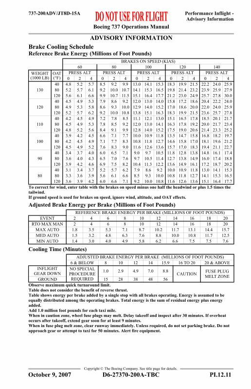
Boeing 737 Operations Manual
Performance Inflight -Advisory Information
737-200ADV/JT8D-15A
Copyright © The Boeing Company. See title page for details.
ADVISORY INFORMATIONAdvisory Information
Brake Cooling ScheduleReference Brake Energy (Millions of Foot Pounds)
Adjusted Brake Energy per Brake (Millions of Foot Pounds)
Cooling Time (Minutes)
BRAKES ON SPEED (KIAS)60 80 100 120 140
WEIGHT (1000 LB)
OAT (°F)
PRESS ALT PRESS ALT PRESS ALT PRESS ALT PRESS ALT0 2 4 0 2 4 0 2 4 0 2 4 0 2 4
13040 4.8 5.2 5.7 8.5 9.2 9.9 13.0 14.1 15.3 18.3 19.9 21.5 22.2 24.0 25.980 5.2 5.7 6.1 9.2 10.0 10.7 14.1 15.3 16.5 19.8 21.4 23.2 23.9 25.9 27.9
120 5.6 6.1 6.6 9.9 10.7 11.5 15.1 16.4 17.7 21.2 23.0 24.9 25.7 27.8 30.0
12040 4.5 4.9 5.3 7.9 8.6 9.2 12.0 13.0 14.0 15.8 17.2 18.6 20.4 22.2 24.080 4.9 5.3 5.8 8.6 9.3 10.0 12.9 14.0 15.2 17.0 18.6 20.0 22.0 24.0 25.9
120 5.2 5.7 6.2 9.2 10.0 10.8 13.8 15.1 16.3 18.3 19.9 21.5 23.6 25.7 27.8
11040 4.2 4.5 4.9 7.2 7.8 8.5 11.1 12.1 13.0 15.1 16.5 17.8 18.5 20.1 21.780 4.5 4.9 5.3 7.8 8.5 9.2 12.0 13.0 14.1 16.3 17.8 19.2 20.0 21.7 23.4
120 4.8 5.2 5.6 8.4 9.1 9.9 12.8 14.0 15.2 17.5 19.0 20.6 21.4 23.3 25.2
10040 3.9 4.2 4.5 6.6 7.1 7.7 10.0 10.9 11.8 13.5 14.7 15.8 16.8 18.2 19.780 4.2 4.5 4.9 7.1 7.7 8.3 10.8 11.8 12.7 14.6 15.8 17.0 18.1 19.6 21.2
120 4.5 4.9 5.2 7.6 8.3 9.0 11.6 12.6 13.6 15.7 17.0 18.3 19.4 21.1 22.7
9040 3.4 3.7 4.0 6.0 6.5 7.1 9.0 9.7 10.5 11.8 12.8 13.8 14.8 16.1 17.480 3.6 4.0 4.3 6.5 7.0 7.6 9.7 10.5 11.4 12.7 13.8 14.9 16.0 17.4 18.8
120 3.9 4.2 4.6 6.9 7.5 8.2 10.4 11.3 12.2 13.6 14.9 16.1 17.2 18.7 20.2
8040 3.1 3.4 3.7 5.2 5.7 6.2 7.9 8.6 9.2 10.0 10.9 11.8 13.0 14.1 15.380 3.3 3.6 3.9 5.6 6.1 6.6 8.5 9.3 10.0 10.8 11.8 12.7 14.1 15.3 16.5
120 3.6 3.9 4.2 6.0 6.6 7.1 9.2 10.0 10.8 11.6 12.6 13.6 15.1 16.4 17.7To correct for wind, enter table with the brakes on speed minus one half the headwind or plus 1.5 times the tailwind.If ground speed is used for brakes on speed, ignore wind, altitude, and OAT effects.
REFERENCE BRAKE ENERGY PER BRAKE (MILLIONS OF FOOT POUNDS)EVENT 2 4 6 8 10 12 14 16 18 20
RTO MAX MAN 2 4 6 8 10 12 14 16 18 20MAX AUTO 1.8 3.5 5.3 7.1 8.7 10.2 11.7 13.1 14.4 15.7MED AUTO 1.5 3.2 4.8 6.3 7.6 8.8 10.0 10.8 11.7 12.5MIN AUTO 1.4 3.0 4.0 4.9 5.8 6.2 6.6 7.5 7.5 7.6
ADJUSTED BRAKE ENERGY PER BRAKE (MILLIONS OF FOOT POUNDS)6 & BELOW 8 10 12 14 15.9 16 TO 20 20 & ABOVE
INFLIGHT GEAR DOWN
NO SPECIAL PROCEDURE REQUIRED
1.0 2.9 4.9 7.0 8.8 CAUTION FUSE PLUG MELT ZONEGROUND 15 28 38 48 56
Observe maximum quick turnaround limit. Table does not consider the benefit of reverse thrust.Table shows energy per brake added by a single stop with all brakes operating. Energy is assumed to be equally distributed among the operating brakes. Total energy is the sum of residual energy plus energy added. Add 1.0 million foot pounds for each taxi mile. When in caution zone, wheel fuse plugs may melt. Delay takeoff and inspect after 30 minutes. If overheat occurs after takeoff, extend gear soon for at least 9 minutes. When in fuse plug melt zone, clear runway immediately. Unless required, do not set parking brake. Do not approach gear or attempt to taxi for 50 minutes. Alert fire equipment.
D6-27370-200A-TBC PI.12.11October 9, 2007

Boeing 737 Operations Manual
Performance Inflight -Advisory Information
737-200ADV/JT8D-15A
Copyright © The Boeing Company. See title page for details.
IntentionallyBlank
PI.12.12 D6-27370-200A-TBC October 9, 2007

Boeing 737 Operations Manual
Performance Inflight - Chapter PIEngine Inoperative Section 13
737-200ADV/JT8D-15A
FAST
-Doc
PI/P
D T
empl
ate
9/1/
99
Copyright © The Boeing Company. See title page for details.
PI.13 Performance Inflight --Engine InoperativeENGINE INOPEngine Inoperative
Max Continuous EPRBased on engine bleed for packs on, engine and wing anti-ice off
EPR Adjustments for Engine Bleeds
TAT (°C)
PRESSURE ALTITUDE (FT)
0 1000 1499 1500 2000 3000 3900 TO 10000 37000
60 1.64 1.64 1.64 1.64 1.64 1.64 1.64 1.6255 1.70 1.70 1.70 1.70 1.70 1.70 1.70 1.6750 1.75 1.75 1.75 1.75 1.75 1.75 1.75 1.7345 1.80 1.80 1.80 1.80 1.80 1.80 1.80 1.7840 1.84 1.84 1.84 1.85 1.85 1.85 1.85 1.8435 1.84 1.84 1.84 1.91 1.91 1.91 1.91 1.8830 1.84 1.84 1.84 1.96 1.96 1.96 1.96 1.9325 1.84 1.84 1.84 2.00 2.00 2.00 2.00 1.9820 1.88 1.88 1.88 2.05 2.05 2.05 2.05 2.0315 1.93 1.93 1.93 2.09 2.09 2.09 2.09 2.0710 1.98 1.98 1.98 2.13 2.13 2.13 2.13 2.115 2.03 2.03 2.03 2.16 2.16 2.17 2.17 2.160 2.07 2.09 2.09 2.16 2.19 2.21 2.21 2.18-5 2.07 2.13 2.14 2.16 2.19 2.23 2.23 2.22-10 2.07 2.13 2.16 2.16 2.19 2.25 2.26 2.24-15 2.07 2.13 2.16 2.16 2.19 2.25 2.28 2.26-20 2.07 2.13 2.16 2.16 2.19 2.25 2.30 2.28-25 2.07 2.13 2.16 2.16 2.19 2.25 2.30 2.28
-30 TO -50 2.07 2.13 2.16 2.16 2.19 2.25 2.30 2.28
BLEED CONFIGURATION
PRESSURE ALTITUDE (FT)0 37000
PACKS OFF 0.03 0.03ENGINE ANTI-ICE ON -0.08 -0.08
ENGINE AND WING ANTI-ICE ON -0.15 -0.15With Gravel Protect switch in “Anti-Ice/Test” position and up to 15000 ft, decrease limit EPR by 0.01.With Gravel Protect switch in “Anti-Ice/Test” position and above 15000 ft, decrease limit EPR by 0.02.
D6-27370-200A-TBC PI.13.1April 7, 2000

Boeing 737 Operations Manual
Performance Inflight -Engine Inoperative
737-200ADV/JT8D-15A
Copyright © The Boeing Company. See title page for details.
ENGINE INOPMAX CONTINUOUS THRUST
Driftdown Speed/Level Off Altitude100 ft/min residual rate of climb
Driftdown/LRC Cruise Range CapabilityGround to Air Miles Conversion
Driftdown/Cruise Fuel and Time
WEIGHT (1000 LB) OPTIMUM DRIFTDOWN
SPEED (KIAS)
LEVEL OFF ALTITUDE (FT)START DRIFT DOWN
LEVEL OFF
ISA + 10°C & BELOW ISA + 15°C ISA + 20°C
130 123 231 13400 12300 11000120 113 222 16000 15100 14100110 104 213 18800 17900 17000100 95 204 21500 20900 2010090 85 194 24400 23900 2330080 76 183 27400 27000 2660070 67 171 30500 30300 3000060 57 158 33900 33700 33600
For A/C pack off below 17000 ft, increase level off altitude by 800 ft.
AIR DISTANCE (NM) GROUND DISTANCE
(NM)
AIR DISTANCE (NM)HEADWIND COMPONENT (KTS) TAILWIND COMPONENT (KTS)
100 80 60 40 20 20 40 60 80 100293 268 247 229 214 200 188 177 168 159 152581 533 492 457 427 400 377 356 337 320 305865 795 735 684 639 600 565 535 507 482 4591146 1055 977 910 851 800 754 714 677 644 6151426 1314 1218 1136 1064 1000 944 893 848 807 7701706 1574 1460 1362 1276 1200 1133 1073 1019 970 9251988 1834 1702 1588 1488 1400 1322 1252 1189 1132 10802273 2097 1946 1815 1701 1600 1511 1430 1359 1293 12342563 2363 2191 2043 1914 1800 1699 1608 1527 1454 1387
AIR DIST (NM)
FUEL REQUIRED (1000 LB)TIME
(HR:MIN)WEIGHT AT START OF DRIFTDOWN (1000 LB)70 80 90 100 110 120 130
200 2.0 2.1 2.3 2.6 2.9 3.1 3.3 0:38400 4.1 4.6 5.1 5.8 6.5 7.1 7.7 1:15600 6.1 6.9 7.7 8.7 9.7 10.6 11.4 1:50800 8.1 9.1 10.2 11.5 12.8 13.9 15.1 2:251000 10.0 11.3 12.7 14.2 15.7 17.2 18.6 2:591200 11.9 13.5 15.1 16.9 18.7 20.3 22.1 3:341400 13.8 15.5 17.4 19.4 21.5 23.5 25.5 4:091600 15.6 17.6 19.7 22.0 24.3 26.5 28.8 4:441800 17.4 19.6 21.9 24.5 27.0 29.5 32.1 5:22
Includes APU fuel burn. Driftdown at optimum driftdown speed and cruise at LRC speed.
PI.13.2 D6-27370-200A-TBC April 7, 2000

Boeing 737 Operations Manual
Performance Inflight -Engine Inoperative
737-200ADV/JT8D-15A
Copyright © The Boeing Company. See title page for details.
ENGINE INOPMAX CONTINUOUS THRUST
Long Range Cruise Altitude Capability100 ft/min residual rate of climb
Long Range Cruise Control
WEIGHT (1000 LB)
PRESS ALT (FT)ISA + 10°C & BELOW ISA + 15°C ISA + 20°C
130 7500 3600120 10800 9000 5100110 14100 12700 10900100 17700 16300 1510090 21300 20000 1870080 24800 24000 2300070 28500 27800 2720060 31700 31300 30800
With engine anti-ice on, decrease altitude capability by 2000 ft.With engine and wing anti-ice on, decrease altitude capability by 4400 ft.
WEIGHT (1000 LB)
PRESSURE ALTITUDE (1000 FT)10 13 15 17 19 21 23 25 27 29
130
EPR 2.04MACH .541KIAS 300
FF/ENG 6933
120
EPR 1.96 2.08 2.16MACH .519 .549 .566KIAS 288 288 286
FF/ENG 6251 6363 6398
110
EPR 1.88 1.99 2.07 2.15MACH .501 .527 .548 .564KIAS 277 276 276 274
FF/ENG 5664 5706 5778 5809
100
EPR 1.81 1.90 1.97 2.06 2.14 2.23MACH .487 .505 .523 .544 .562 .579KIAS 269 264 264 264 262 260
FF/ENG 5190 5097 5123 5196 5224 5294
90
EPR 1.73 1.82 1.88 1.95 2.04 2.12 2.20MACH .469 .489 .500 .517 .539 .557 .575KIAS 259 256 252 251 251 250 248
FF/ENG 4722 4622 4550 4550 4619 4651 4709
80
EPR 1.65 1.73 1.79 1.85 1.92 2.00 2.09 2.17 2.27MACH .447 .469 .482 .495 .509 .530 .551 .569 .593KIAS 247 245 242 240 237 237 237 235 235
FF/ENG 4245 4159 4086 4030 3995 4040 4090 4132 4246
70
EPR 1.57 1.64 1.70 1.75 1.81 1.88 1.95 2.04 2.13 2.22MACH .423 .444 .460 .473 .487 .500 .517 .540 .559 .578KIAS 234 232 231 228 227 223 222 223 221 219
FF/ENG 3779 3692 3642 3576 3527 3474 3477 3537 3565 3614
60
EPR 1.48 1.55 1.59 1.65 1.70 1.76 1.83 1.90 1.99 2.08MACH .395 .417 .431 .446 .461 .475 .491 .511 .532 .555KIAS 218 217 216 215 214 212 210 210 210 210
FF/ENG 3301 3230 3178 3126 3085 3027 2999 3011 3045 3082
D6-27370-200A-TBC PI.13.3April 7, 2000

Boeing 737 Operations Manual
Performance Inflight -Engine Inoperative
737-200ADV/JT8D-15A
Copyright © The Boeing Company. See title page for details.
ENGINE INOPMAX CONTINUOUS THRUST
Long Range Cruise Diversion Fuel and TimeGround to Air Miles Conversion
Reference Fuel and Time Required at Check Point
Fuel Required Adjustment (1000 LB)
AIR DISTANCE (NM) GROUND DISTANCE
(NM)
AIR DISTANCE (NM)HEADWIND COMPONENT (KTS) TAILWIND COMPONENT (KTS)
100 80 60 40 20 20 40 60 80 100297 272 249 230 214 200 190 181 173 166 159600 547 501 462 429 400 380 362 345 330 317906 824 753 694 644 600 570 542 517 494 4741214 1104 1007 927 860 800 759 722 689 658 6311526 1385 1262 1161 1076 1000 949 902 860 821 7871840 1668 1519 1396 1292 1200 1139 1082 1031 984 9432157 1953 1776 1630 1508 1400 1328 1262 1202 1147 10992478 2242 2036 1867 1725 1600 1517 1441 1371 1309 12532802 2531 2296 2103 1942 1800 1706 1620 1542 1471 1408
AIR DIST (NM)
PRESSURE ALTITUDE (1000 FT)10 16 20 24 28
FUEL (1000 LB)
TIME (HR:MIN)
FUEL (1000 LB)
TIME (HR:MIN)
FUEL (1000 LB)
TIME (HR:MIN)
FUEL (1000 LB)
TIME (HR:MIN)
FUEL (1000 LB)
TIME (HR:MIN)
200 3.2 0:43 2.8 0:41 2.5 0:40 2.4 0:38 2.2 0:37400 6.5 1:24 5.7 1:20 5.3 1:16 5.1 1:13 4.9 1:09600 9.7 2:06 8.5 1:59 8.0 1:53 7.7 1:48 7.4 1:41800 12.9 2:48 11.4 2:38 10.7 2:30 10.3 2:23 10.0 2:14
1000 15.9 3:31 14.1 3:18 13.3 3:08 12.7 2:58 12.4 2:481200 19.0 4:14 16.8 3:58 15.8 3:46 15.2 3:34 14.8 3:211400 22.0 4:59 19.5 4:39 18.3 4:25 17.6 4:11 17.2 3:561600 25.0 5:44 22.1 5:20 20.8 5:05 19.9 4:48 19.4 4:311800 27.9 6:30 24.7 6:02 23.2 5:45 22.2 5:26 21.6 5:07
REFERENCE FUEL REQUIRED (1000 LB)
WEIGHT AT CHECK POINT (1000 LB)70 80 90 100 110 120
5 -0.4 -0.2 0.0 0.4 0.8 1.610 -0.9 -0.5 0.0 0.9 1.8 3.315 -1.4 -0.7 0.0 1.4 2.8 4.820 -1.9 -1.0 0.0 1.8 3.7 6.225 -2.4 -1.2 0.0 2.3 4.7 7.530 -2.9 -1.5 0.0 2.8 5.6 8.6
PI.13.4 D6-27370-200A-TBC April 7, 2000

Boeing 737 Operations Manual
Performance Inflight -Engine Inoperative
737-200ADV/JT8D-15A
Copyright © The Boeing Company. See title page for details.
ENGINE INOPMAX CONTINUOUS THRUST
HoldingFlaps Up
WEIGHT (1000 LB)
PRESSURE ALTITUDE (FT)1500 5000 10000 15000 20000 25000 30000
130EPR 1.66 1.77 1.95 2.18KIAS 243 246 246 247
FF/ENG 6090 6080 6130 6460
120EPR 1.60 1.70 1.87 2.08KIAS 232 236 236 237
FF/ENG 5610 5570 5560 5780
110EPR 1.54 1.63 1.79 1.98 2.22KIAS 220 223 227 227 228
FF/ENG 5150 5090 5060 5140 5440
100EPR 1.49 1.57 1.71 1.89 2.11KIAS 210 211 216 216 217
FF/ENG 4700 4630 4570 4570 4760
90EPR 1.43 1.50 1.63 1.79 1.99 2.24KIAS 210 210 210 210 210 210
FF/ENG 4330 4250 4150 4100 4170 4440
80EPR 1.39 1.45 1.56 1.70 1.88 2.11KIAS 210 210 210 210 210 210
FF/ENG 4010 3930 3820 3750 3740 3890
70EPR 1.35 1.41 1.51 1.63 1.79 2.00 2.24KIAS 210 210 210 210 210 210 210
FF/ENG 3740 3660 3550 3460 3420 3480 3680
60EPR 1.32 1.37 1.46 1.57 1.72 1.90 2.13KIAS 210 210 210 210 210 210 210
FF/ENG 3500 3420 3310 3230 3160 3160 3270This table includes 5% additional fuel for holding in a racetrack pattern.
D6-27370-200A-TBC PI.13.5April 7, 2000

Boeing 737 Operations Manual
Performance Inflight -Engine Inoperative
737-200ADV/JT8D-15A
Copyright © The Boeing Company. See title page for details.
IntentionallyBlank
PI.13.6 D6-27370-200A-TBC April 7, 2000

Boeing 737 Operations Manual
Performance Inflight - Chapter PIGear Down Section 14
737-200ADV/JT8D-15A
FAST
-Doc
PI/P
D T
empl
ate
9/1/
99
Copyright © The Boeing Company. See title page for details.
PI.14 Performance Inflight --Gear DownGEAR DOWNGear Down
220 KIAS Cruise Altitude CapabilityMax Cruise Thrust, 100 ft/min residual rate of climb
220 KIAS Cruise Control
WEIGHT (1000 LB)
PRESSURE ALTITUDE (FT)ISA + 10°C & BELOW ISA + 15°C ISA + 20°C
130 13700 9700120 16200 13000 7700110 18400 15800 11800100 20400 18100 1490090 22200 20000 1720080 23600 21800 1910070 24800 23200 2100060 25800 24300 22400
WEIGHT (1000 LB)
PRESSURE ALTITUDE (1000 FT)10 13 15 17 19 21 23
130
EPR 1.73 1.83 1.91 2.00MACH .399 .422 .438 .456KIAS 220 220 220 220
FF/ENG 4482 4474 4496 4562
120
EPR 1.69 1.78 1.86 1.94 2.03MACH .399 .422 .438 .456 .474KIAS 220 220 220 220 220
FF/ENG 4263 4247 4247 4280 4352
110
EPR 1.64 1.74 1.81 1.88 1.97 2.06MACH .399 .422 .438 .456 .474 .493KIAS 220 220 220 220 220 220
FF/ENG 4071 4043 4033 4044 4086 4165
100
EPR 1.61 1.70 1.76 1.83 1.91 2.00 2.09MACH .399 .422 .438 .456 .474 .493 .513KIAS 220 220 220 220 220 220 220
FF/ENG 3905 3866 3850 3846 3866 3922 4012
90
EPR 1.58 1.66 1.72 1.79 1.87 1.95 2.04MACH .399 .422 .438 .456 .474 .493 .513KIAS 220 220 220 220 220 220 220
FF/ENG 3765 3720 3699 3689 3692 3725 3805
80
EPR 1.55 1.63 1.69 1.76 1.83 1.91 2.00MACH .399 .422 .438 .456 .474 .493 .513KIAS 220 220 220 220 220 220 220
FF/ENG 3649 3601 3575 3559 3553 3572 3635
70
EPR 1.53 1.61 1.67 1.73 1.80 1.87 1.96MACH .399 .422 .438 .456 .474 .493 .513KIAS 220 220 220 220 220 220 220
FF/ENG 3550 3500 3470 3449 3438 3447 3493
60
EPR 1.52 1.59 1.64 1.71 1.77 1.85 1.93MACH .399 .422 .438 .456 .474 .493 .513KIAS 220 220 220 220 220 220 220
FF/ENG 3472 3419 3388 3364 3349 3351 3387
D6-27370-200A-TBC PI.14.1April 7, 2000

Boeing 737 Operations Manual
Performance Inflight -Gear Down
737-200ADV/JT8D-15A
Copyright © The Boeing Company. See title page for details.
GEAR DOWNGear Down
220 KIAS Enroute Fuel and TimeGround to Air Miles Conversion
Reference Fuel and Time Required at Check Point
Fuel Required Adjustment (1000 LB)
Descent at 220 KIAS
AIR DISTANCE (NM) GROUND DISTANCE
(NM)
AIR DISTANCE (NM)HEADWIND COMPONENT (KTS) TAILWIND COMPONENT (KTS)
100 80 60 40 20 20 40 60 80 100335 297 264 239 218 200 189 179 170 161 154678 599 531 479 437 400 378 357 339 323 3081021 901 799 720 656 600 566 535 507 483 4611364 1204 1067 961 875 800 755 714 677 644 6141707 1506 1334 1201 1093 1000 943 892 845 804 7672050 1808 1602 1442 1312 1200 1132 1071 1015 964 9202393 2111 1871 1683 1531 1400 1321 1248 1183 1125 10742736 2413 2138 1923 1750 1600 1510 1427 1353 1286 12273079 2715 2406 2164 1969 1800 1698 1605 1521 1446 1380
AIR DIST (NM)
PRESSURE ALTITUDE (1000 FT)10 14 18 22 26
FUEL (1000 LB)
TIME (HR:MIN)
FUEL (1000 LB)
TIME (HR:MIN)
FUEL (1000 LB)
TIME (HR:MIN)
FUEL (1000 LB)
TIME (HR:MIN)
FUEL (1000 LB)
TIME (HR:MIN)
200 5.6 0:50 5.1 0:47 4.7 0:45 4.4 0:43 4.2 0:41400 11.4 1:37 10.5 1:32 9.7 1:27 9.2 1:22 9.0 1:18600 17.1 2:24 15.8 2:16 14.7 2:08 13.9 2:01 13.6 1:54800 22.7 3:11 21.0 3:00 19.5 2:50 18.5 2:40 18.1 2:31
1000 28.2 3:58 26.1 3:45 24.3 3:32 23.0 3:19 22.6 3:081200 33.7 4:45 31.2 4:29 29.0 4:13 27.5 3:59 27.0 3:441400 39.1 5:32 36.2 5:13 33.7 4:55 31.9 4:38 31.3 4:211600 44.5 6:20 41.2 5:58 38.4 5:37 36.3 5:17 35.6 4:581800 49.8 7:07 46.1 6:42 43.0 6:18 40.7 5:56 39.8 5:34
REFERENCE FUEL REQUIRED (1000 LB)
WEIGHT AT CHECK POINT (1000 LB)70 80 90 100 110 120
5 -0.2 -0.1 0.0 0.2 0.5 0.810 -0.5 -0.3 0.0 0.5 1.1 1.715 -0.7 -0.4 0.0 0.7 1.6 2.620 -0.9 -0.5 0.0 0.9 2.1 3.425 -1.1 -0.6 0.0 1.1 2.5 4.130 -1.2 -0.7 0.0 1.3 2.8 4.735 -1.3 -0.7 0.0 1.4 3.2 5.240 -1.4 -0.8 0.0 1.5 3.4 5.645 -1.5 -0.9 0.0 1.6 3.6 5.9
PRESSURE ALT (1000 FT) 5 10 15 17 19 21 23 25 27 29 31 33DISTANCE (NM) 19 28 43 47 51 54 58 62 66 70 74 78TIME (MINUTES) 7 9 13 14 15 16 17 17 18 19 19 20
PI.14.2 D6-27370-200A-TBC April 7, 2000

Boeing 737 Operations Manual
Performance Inflight -Gear Down
737-200ADV/JT8D-15A
Copyright © The Boeing Company. See title page for details.
GEAR DOWNGear Down
HoldingFlaps Up
WEIGHT (1000 LB)
PRESSURE ALTITUDE (FT)1500 5000 10000 15000 20000 25000
130EPR 1.55 1.65 1.80KIAS 243 246 246
FF/ENG 5310 5310 5250
120EPR 1.50 1.59 1.73 1.92KIAS 232 236 236 237
FF/ENG 4870 4880 4820 4850
110EPR 1.45 1.52 1.67 1.83 2.05KIAS 220 223 227 227 228
FF/ENG 4460 4440 4410 4380 4540
100EPR 1.40 1.46 1.59 1.75 1.94KIAS 210 211 216 216 217
FF/ENG 4090 4020 4010 3960 4000
90EPR 1.38 1.44 1.54 1.68 1.86 2.08KIAS 210 210 210 210 210 210
FF/ENG 3920 3840 3730 3650 3630 3780
80EPR 1.36 1.41 1.51 1.64 1.81 2.02KIAS 210 210 210 210 210 210
FF/ENG 3780 3700 3590 3510 3470 3570
70EPR 1.34 1.39 1.49 1.61 1.77 1.98KIAS 210 210 210 210 210 210
FF/ENG 3670 3580 3470 3390 3340 3400
60EPR 1.33 1.38 1.47 1.59 1.74 1.94KIAS 210 210 210 210 210 210
FF/ENG 3570 3480 3380 3290 3230 3270This table includes 5% additional fuel for holding in a racetrack pattern.
D6-27370-200A-TBC PI.14.3April 7, 2000

Boeing 737 Operations Manual
Performance Inflight -Gear Down
737-200ADV/JT8D-15A
Copyright © The Boeing Company. See title page for details.
IntentionallyBlank
PI.14.4 D6-27370-200A-TBC April 7, 2000
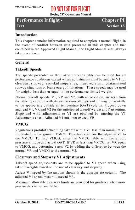
Boeing 737 Operations Manual
Performance Inflight - Chapter PIText Section 15
737-200ADV/JT8D-15A
FAST
-Doc
PI/P
D T
empl
ate
9/1/
99
Copyright © The Boeing Company. See title page for details.
PI.15 Performance Inflight --TextText
IntroductionThis chapter contains information required to complete a normal flight. Inthe event of conflict between data presented in this chapter and thatcontained in the Approved Flight Manual, the Flight Manual shall alwaystake precedence.
General
Takeoff SpeedsThe speeds presented in the Takeoff Speeds table can be used for allperformance conditions except where adjustments must be made to V1 forclearway, stopway, anti-skid inoperative, improved climb, contaminatedrunway situations or brake energy limitations. These speeds may be usedfor weights less than or equal to the performance limited weight.Normal takeoff speeds, V1, VR and V2, with anti-skid on, are read fromthe table by entering with station pressure altitude and moving horizontallyto the appropriate outside air temperature (OAT) column. Proceed downand read V1, VR and V2 for the anticipated takeoff weight and flap setting.Slope and wind adjustments to V1 are obtained by entering the V1Adjustments chart. Adjusted V1 must not exceed VR.
VMCGRegulations prohibit scheduling takeoff with a V1 less than minimum V1for control on the ground, VMCG. Therefore compare the adjusted V1 tothe VMCG. To find VMCG, enter the VMCG table with the airportpressure altitude and actual OAT. If VR is less than VMCG, set VR equalto VMCG, and determine a new V2 by adding the difference between thenormal VR and VMCG to the normal V2.
Clearway and Stopway V1 AdjustmentsTakeoff speed adjustments are to be applied to V1 speed when usingtakeoff weights based on the use of clearway and stopway. Adjust V1 speed by the amount shown in the appropriate column. Theadjusted V1 speed must not exceed VR.Maximum allowable clearway limits are provided for guidance when moreprecise data is not available.
D6-27370-200A-TBC PI.15.1October 8, 2004

Boeing 737 Operations Manual
Performance Inflight -Text
737-200ADV/JT8D-15A
Copyright © The Boeing Company. See title page for details.
Stab Trim To find takeoff stabilizer trim setting, enter the Stab Trim Setting tablewith takeoff flap setting and center of gravity (C.G. % MAC) and readrequired stabilizer trim units.
VREFThe Reference Speed table contains flaps 40, 30 and 15 landing speeds fora given weight. Apply wind adjustments shown as required.
Flap Maneuver SpeedsThis table provides the flap speed schedule for recommended maneuveringspeed. The speed schedule is a function of weight and will provideadequate maneuver margin above stall at all weights.During flap retraction/extension, movement of the flap to the next positionshould be initiated when reaching the maneuver speed for the existing flap.
Slush/Standing Water TakeoffExperience has shown that aircraft performance may deterioratesignificantly on runways covered with snow, slush, standing water or ice.Therefore, reductions in runway/obstacle limited takeoff weight andrevised takeoff speeds are necessary. The tables are intended for guidancein accordance with advisory material and assume an engine failure at thecritical point during the takeoff.The entire runway is assumed to be completely covered by a contaminantof uniform thickness and density. Therefore this information isconservative when operating under typical colder weather conditionswhere patches of slush exist and some degree of sanding is common.Takeoffs in slush/standing water depths greater than 0.50 inches (13 mm)are not recommended because of possible airplane damage as a result ofslush/standing water impingement on the airplane structure. The use ofassumed temperature method for reduced thrust is not allowed oncontaminated runways. Interpolation for slush/standing water depthsbetween the values shown is permitted.Takeoff weight determination:1. Enter the Weight Adjustment table with the dry field/obstacle limitweight to obtain the weight reduction for the slush/standing water depthand airport pressure altitude.2. Adjust field length available for temperature by amount shown on chart.3. Enter the VMCG Limit Weight table with the adjusted field length andpressure altitude to obtain the slush/standing water limit weight withrespect to minimum field length required for VMCG speed.
PI.15.2 D6-27370-200A-TBC October 8, 2004

Boeing 737 Operations Manual
Performance Inflight -Text
737-200ADV/JT8D-15A
Copyright © The Boeing Company. See title page for details.
4. The maximum allowable takeoff weight in slush/standing water is thelesser of the limit weights found in steps 1 and 3.Takeoff speed determination:1. Determine takeoff speeds V1, VR and V2 for actual brake release weightusing the Takeoff Speeds table in this section.2. If VMCG limited, set V1=VMCG. If not limited by VMCGconsiderations, enter the V1 Adjustment table with actual brake releaseweight to determine the V1 reduction to apply to V1 speed. If the adjustedV1 is less than VMCG, set V1=VMCG.
Slippery Runway TakeoffAirplane braking action is reported as good, medium or poor, dependingon existing runway conditions. If braking action is reported as good,conditions should not be expected to be as good as on clean dry runways.The value “good” is comparative and is intended to mean that airplanesshould not experience braking or directional control difficulties whenstopping. The performance level used to calculate the “good” data isconsistent with wet runway testing done on early Boeing jets. Theperformance level used to calculate the “poor” data reflects a runwaycovered with wet ice. Performance is based on reversers operating and a 15ft. screen height at the end of the runway. The tables provided are used inthe same manner as the Slush/Standing Water tables.
Anti-skid InoperativeFor anti-skid inoperative, the runway limited maximum gross weight atbrake release and the V1 speed must be reduced to allow for the effect onaccelerate-stop performance as detailed in the Approved Airplane FlightManual. Obstacle clearance capability must also be considered since thereduced V1 speed will increase the distance required to achieve a givenheight above the runway following engine failure. A simplified methodwhich conservatively accounts for the effects of anti-skid inoperative isshown below. Reduce the dry runway/obstacle limited weight at brakerelease obtained from the takeoff performance charts in this section orfrom the specific airport analysis and the associated V1 (i.e., V1 for therunway/obstacle limited weight at brake release) by the weight and V1values shown in the table below. (Note that the resulting V1 must not beless than VMCG value.)
D6-27370-200A-TBC PI.15.3October 8, 2004

Boeing 737 Operations Manual
Performance Inflight -Text
737-200ADV/JT8D-15A
Copyright © The Boeing Company. See title page for details.
For takeoff below the anti-skid inoperative limited weight it is onlynecessary to ensure that the V1 speed set does not exceed the anti-skidlimited V1 value.
If the resulting V1 is less than minimum V1, takeoff is permitted with V1set equal to VMCG. Detailed analysis for the specific case from the AFM may yield a lessrestrictive penalty.
Takeoff EPRTo find Takeoff EPR based on normal engine bleed for air conditioningpacks on, enter Takeoff EPR table with airport pressure altitude and airportOAT and read EPR. For packs off operation, apply the EPR adjustmentshown below the table. No takeoff EPR adjustment is required for winganti-ice operation.
Reduced Takeoff EPRThe tables present the allowable Takeoff EPR Reduction as a function ofActual OAT and Surplus Weight which is defined as the differencebetween the Performance Limited TOGW and the Actual TOGW. Thesetables are valid for engine A/C bleed on or off, any flap setting. They arenot valid when the maximum takeoff weight is limited by obstacles, brakeenergy or tire speed. Since the tables are conservative, larger reductions inEPR may be achieved under some conditions by using the AssumedTemperature Method described in the AFM Appendix.Enter the Field Length Limited section of the table appropriate for theairplane pressure altitude with the Surplus Weight based on the field lengthlimit (i.e., Field length limited weight minus actual weight). Read theallowable Takeoff EPR Reduction. Then enter the Climb Limited sectionof the table with the Surplus Weight based on the climb limit anddetermine the allowable Takeoff EPR Reduction. Use the smaller of the
ANTI-SKID INOPERATIVE ADJUSTMENTSRUNWAY LENGTH
(FT)WEIGHT ADJUSTMENT
(LB)V1 ADJUSTMENT
(KTS)LESS THAN 5000 CHECK AFM
5000 -13000 -286000 13000 -257000 -13000 -238000 -13000 -229000 -13000 -2010000 -13000 -1911000 -13000 -1812000 -13000 -1713000 -13000 -16
PI.15.4 D6-27370-200A-TBC April 7, 2006

Boeing 737 Operations Manual
Performance Inflight -Text
737-200ADV/JT8D-15A
Copyright © The Boeing Company. See title page for details.
two reductions. Enter the Minimum EPR table with the pressure altitude.The Takeoff EPR, after the reduction is applied, should not be less thanthis minimum. Apply the noted V1, VR and V2 adjustments.Takeoff with assumed temperature reduced thrust is not permitted when:runway is contaminated with water, ice, slush or snow; anti-skid isinoperative. Use of this procedure is not recommended if potentialwindshear conditions exist.
Max Climb EPRThis table shows Max Climb EPR based on normal engine bleed for packson and anti-ice off. Enter the table with pressure altitude and TAT andread EPR. EPR adjustments are shown for anti-ice operation.
Go-around EPRTo find Go-around EPR based on normal engine bleed for packs on andwing anti-ice off, enter the Go-around EPR table with airport pressurealtitude and reported OAT or TAT and read EPR. For packs off, apply theEPR adjustment shown below the table. EPR adjustments are also shownfor engine and wing anti-ice operations.
Flight with Unreliable Airspeed / Turbulent Air PenetrationPitch attitude and average EPR information is provided for use in allphases of flight in the event of unreliable airspeed/Mach indicationsresulting from blocking or freezing of the pitot system. Loss of radome orturbulent air may also cause unreliable airspeed/Mach indications. Thecruise table in this section may also be used for turbulent air penetration.Pitch attitude is shown in bold type for emphasis since altitude and/orvertical speed indications may also be unreliable.
All Engines
Long Range Cruise Maximum Operating AltitudeMaximum altitudes are shown for a given cruise weight and maneuvercapability. This table considers both thrust and buffet limits, providing themore limiting of the two. Any data that is thrust limited is denoted by anasterisk and represents only a thrust limited condition in level flight with100 ft/min residual rate of climb. Flying above these altitudes withsustained banks in excess of approximately 15° may cause the airplane tolose speed and/or altitude.Note that the altitudes shown in the table are limited to the maximumcertified altitude of 37000 ft.
D6-27370-200A-TBC PI.15.5April 7, 2006

Boeing 737 Operations Manual
Performance Inflight -Text
737-200ADV/JT8D-15A
Copyright © The Boeing Company. See title page for details.
Long Range Cruise ControlThese tables provide target EPR, Long Range Cruise Mach number, KIASand standard day fuel flow per engine for the airplane weight and pressurealtitude. As indicated by the shaded area, at optimum altitude .72Mapproximates the Long Range Cruise Mach schedule.
Long Range Cruise Enroute Fuel and TimeLong Range Cruise Enroute Fuel and Time tables are provided todetermine remaining time and fuel required to destination. The data isbased on Long Range Cruise and .70/280/250 descent. Tables arepresented for low altitudes and high altitudes.To determine remaining fuel and time required, first enter the Ground toAir Miles Conversion table to convert ground distance and enroute wind toan equivalent still air distance for use with the Reference Fuel and Timetables. Next, enter the Reference Fuel and Time table with air distancefrom the Ground to Air Miles Conversion table and the desired altitude andread Reference Fuel and Time Required. Lastly, enter the Fuel RequiredAdjustment table with the Reference Fuel and the actual weight atcheckpoint to obtain fuel required to destination.
Long Range Cruise Wind-Altitude TradeWind is a factor which may justify operations considerably below optimumaltitude. For example, a favorable wind component may have an effect onground speed which more than compensates for the loss in air range.Using this table, it is possible to determine the break-even wind (advantagenecessary or disadvantage that can be tolerated) to maintain the same rangeat another altitude and long range cruise speed. The tables make noallowance for climb or descent time, fuel or distance, and are based oncomparing ground fuel mileage.
DescentDistance and time for descent are shown for a .70/280/250 descent speedschedule. Enter the table with top of descent pressure altitude and readdistance in nautical miles and time in minutes. Data is based on flight idlethrust descent in zero wind. Allowances are included for a straight-inapproach with gear down and landing flaps at the outer marker.
HoldingTarget EPR, indicated airspeed and fuel flow per engine information istabulated for holding with flaps up based on the optimum holding speedschedule. This is the higher of the maximum endurance speed and the
PI.15.6 D6-27370-200A-TBC April 7, 2006

Boeing 737 Operations Manual
Performance Inflight -Text
737-200ADV/JT8D-15A
Copyright © The Boeing Company. See title page for details.
maneuvering speed. Small variations in airspeed will not appreciablyaffect the overall endurance time. Enter the table with weight and pressurealtitude to read EPR, KIAS and fuel flow per engine.
Advisory Information
Autobrake Landing DistanceThe Autobrake Landing Distance tables are provided as advisoryinformation to assist in the selection of the most desirable autobrakesetting for a given field length. It is not to be used to determine requiredfield length. This data reflects actual landing distances on a dry runway forsetting MINIMUM through MAXIMUM, from touchdown to full stop,with or without reverse thrust. The tables include typical flare distancesfrom threshold.To use the Autobrake Landing Distance table, determine the appropriatetable to use. The Digital Autobrake Landing Distance table is onlyapplicable if Autobrake Control Valve Module, Boeing part number60800263 is installed. Enter the chart with the estimated approach speedand determine the actual stopping distance from touchdown for a givenautobrake setting. If airspeed is used for approach speed, adjust landingdistance for pressure altitude and tailwind effects.Selection of an autobrake setting results in a constant rate of deceleration.Maximum effort manual braking should achieve shorter landing distancethan the MAXIMUM setting.
Slippery Runway Landing DistanceLanding distances are the actual landing distances and do not include the1.67% regulatory factor. Therefore they cannot be used to determinedispatch required landing field length. When landing on slippery runwaysor runways contaminated with ice, snow, slush or standing water, thereported braking action must be considered. If the surface is affected bywater, snow or ice, and the braking action is reported as “good,” conditionsshould not be expected to be as good as on clean dry runways. The value“good” is comparative and is intended to mean that airplanes should notexperience braking or directional control difficulties when landing. Theperformance level used to calculate the “good” data is consistent with wetrunway testing done on early Boeing jets. The performance level used tocalculate the “poor” data reflects runways covered with wet ice. Readlanding distance for the reported braking action at the airplane weight, andthen apply the adjustments for airport pressure altitude and approach speedas required.
D6-27370-200A-TBC PI.15.7April 7, 2006

Boeing 737 Operations Manual
Performance Inflight -Text
737-200ADV/JT8D-15A
Copyright © The Boeing Company. See title page for details.
Non-normal Configuration Landing DistanceAdvisory information is provided to support non-normal configurationsthat affect landing performance of the airplane. Landing distances areshown for dry runway and good, medium and poor reported braking action.Each non-normal configuration is listed with its recommended approachspeed. Landing distance can be determined for the reference landingweight and then adjusted for actual weight and pressure altitude.
Brake Cooling ScheduleAdvisory information is provided to assist in avoiding the problemsassociated with hot brakes. For normal operation, most landings are atweights below the AFM quick turnaround limit weight.Use of the recommended cooling schedule will help avoid brake overheatand fuse plug problems that could result from repeated landings at shorttime intervals or a rejected takeoff.Enter the Brake Cooling Schedule table with the airplane weight andbrakes on speed, adjusted for wind at the appropriate temperature andaltitude condition. Instructions for applying wind adjustments are includedbelow the table. Linear interpolation may be used to obtain intermediatevalues. The resulting number is the reference brake energy per brake inmillions of foot-pounds, and represents the amount of energy absorbed byeach brake during a rejected takeoff.To determine the energy per brake absorbed during landing, enter theAdjusted Brake Energy Per Brake table with the reference brake energy perbrake and the type of braking used during landing (RTO Max Man, MaxAuto, Med Auto or Min Auto). The resulting number is the adjusted brakeenergy per brake and represents the energy absorbed in each brake duringthe landing.The recommended cooling time is found in the final table by entering withthe adjusted brake energy per brake. Times are provided for groundcooling and inflight gear down cooling.
Engine Inoperative
Max Continuous EPRPower setting is based on one engine operating with one A/C packoperating and all anti-ice bleeds off. Enter the table with pressure altitudeand TAT to read EPR.It is desirable to maintain engine thrust within the limits of the Max Cruisethrust rating. However, where thrust in excess of Max Cruise rating isrequired, such as for meeting terrain clearance, ATC altitude assignments,
PI.15.8 D6-27370-200A-TBC April 7, 2006
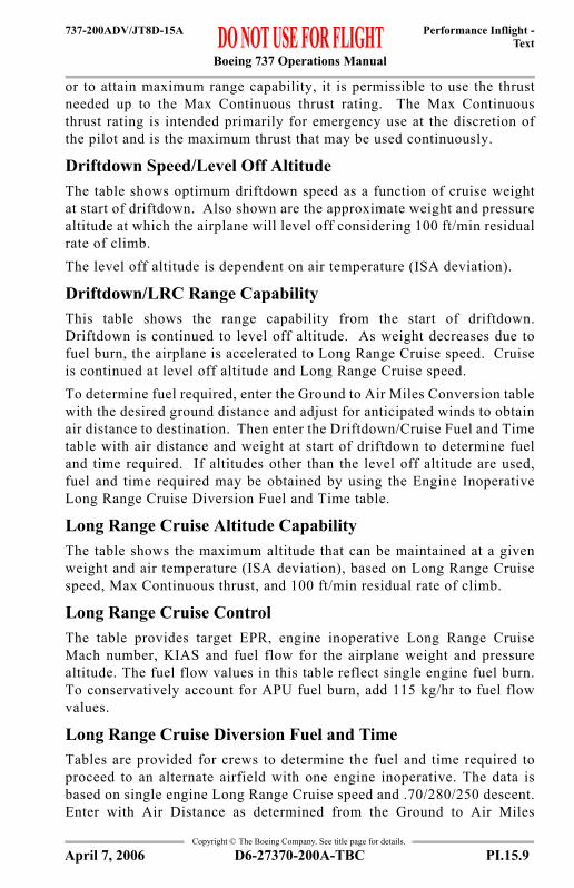
Boeing 737 Operations Manual
Performance Inflight -Text
737-200ADV/JT8D-15A
Copyright © The Boeing Company. See title page for details.
or to attain maximum range capability, it is permissible to use the thrustneeded up to the Max Continuous thrust rating. The Max Continuousthrust rating is intended primarily for emergency use at the discretion ofthe pilot and is the maximum thrust that may be used continuously.
Driftdown Speed/Level Off AltitudeThe table shows optimum driftdown speed as a function of cruise weightat start of driftdown. Also shown are the approximate weight and pressurealtitude at which the airplane will level off considering 100 ft/min residualrate of climb.The level off altitude is dependent on air temperature (ISA deviation).
Driftdown/LRC Range CapabilityThis table shows the range capability from the start of driftdown.Driftdown is continued to level off altitude. As weight decreases due tofuel burn, the airplane is accelerated to Long Range Cruise speed. Cruiseis continued at level off altitude and Long Range Cruise speed.To determine fuel required, enter the Ground to Air Miles Conversion tablewith the desired ground distance and adjust for anticipated winds to obtainair distance to destination. Then enter the Driftdown/Cruise Fuel and Timetable with air distance and weight at start of driftdown to determine fueland time required. If altitudes other than the level off altitude are used,fuel and time required may be obtained by using the Engine InoperativeLong Range Cruise Diversion Fuel and Time table.
Long Range Cruise Altitude CapabilityThe table shows the maximum altitude that can be maintained at a givenweight and air temperature (ISA deviation), based on Long Range Cruisespeed, Max Continuous thrust, and 100 ft/min residual rate of climb.
Long Range Cruise ControlThe table provides target EPR, engine inoperative Long Range CruiseMach number, KIAS and fuel flow for the airplane weight and pressurealtitude. The fuel flow values in this table reflect single engine fuel burn.To conservatively account for APU fuel burn, add 115 kg/hr to fuel flowvalues.
Long Range Cruise Diversion Fuel and TimeTables are provided for crews to determine the fuel and time required toproceed to an alternate airfield with one engine inoperative. The data isbased on single engine Long Range Cruise speed and .70/280/250 descent.Enter with Air Distance as determined from the Ground to Air Miles
D6-27370-200A-TBC PI.15.9April 7, 2006
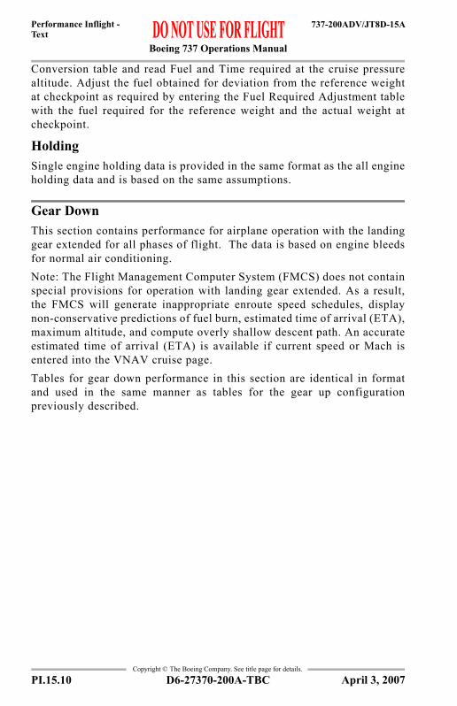
Boeing 737 Operations Manual
Performance Inflight -Text
737-200ADV/JT8D-15A
Copyright © The Boeing Company. See title page for details.
Conversion table and read Fuel and Time required at the cruise pressurealtitude. Adjust the fuel obtained for deviation from the reference weightat checkpoint as required by entering the Fuel Required Adjustment tablewith the fuel required for the reference weight and the actual weight atcheckpoint.
HoldingSingle engine holding data is provided in the same format as the all engineholding data and is based on the same assumptions.
Gear DownThis section contains performance for airplane operation with the landinggear extended for all phases of flight. The data is based on engine bleedsfor normal air conditioning.Note: The Flight Management Computer System (FMCS) does not containspecial provisions for operation with landing gear extended. As a result,the FMCS will generate inappropriate enroute speed schedules, displaynon-conservative predictions of fuel burn, estimated time of arrival (ETA),maximum altitude, and compute overly shallow descent path. An accurateestimated time of arrival (ETA) is available if current speed or Mach isentered into the VNAV cruise page.Tables for gear down performance in this section are identical in formatand used in the same manner as tables for the gear up configurationpreviously described.
PI.15.10 D6-27370-200A-TBC April 3, 2007

Boeing 737 Operations Manual
Performance Inflight - Chapter PIGeneral Section 20
737-200ADV/JT8D-17A
FAST
-Doc
PI/P
D T
empl
ate
9/1/
99
Copyright © The Boeing Company. See title page for details.
PI.20 Performance Inflight --GeneralGeneral
Takeoff Speeds
V1 ADJUSTMENTSWIND SLOPE
SUBTRACT 1 KT PER5 KTS TAILWIND
SUBTRACT 1 KT PER1% DOWN SLOPE
REDUCE VR BY 1 KNOT AND V2 BY
BOXED AREA INDICATES PERFORMANCE AFFECTED BY MINIMUM CONTROL SPEED,MINIMUM FIELD LENGTH FOR LIGHTEST WEIGHT ABOVE BOXED AREA IS REQUIRED.
PRESSUREALTITUDE1000 FT
°F°C°F°C°F°C°F°C°F°C°F°C
OAT
FLAPS
1
2
5
10
15
V1 R 2V V V1 R 2V V V1 R 2V V V1 R 2V V V1 R 2V V V1 R 2V V
to
to
to
to
to
to
to
to
to
to
to
to
to
to
to
to
to
to
to
to
to
to
to
to
111 121 44 49
43 86 6 30
108 121
86 103 30 39
25
42 49
9 TO 10
7 TO 9
5 TO 7
3 TO 5
1 TO 3
-1 TO 1 to
to
to-65 30-54 - 1-65 76-54 24-65 98-54 36
-65 16-54 - 9 31 65 0 18 77 94 25 34 99 110 37 43
-65 9-54 -13 17 42- 8 5 66 87 19 31 95 107 35 41
-65 10-54 -12
-12 0
88 101 32 38
122 130 50 54
11 36-11 2
1 29 87 100 31 37102 119 39 48122 130 50 54
37 85 3 29
101 112 38 44
49 54120 130
1000 LB130120110100 90 80 70130120110100 90 80 70130120110100 90 80 70120110100 90 80 70110100 90 80 70100 90 80 70
157150142135127118109152145139131123114
148143135128120112
137130123115
127119112
117109
160153145137128120110154147140133124116106151144137130122113
139132124116
128121113
118111
165158151144136128120159153146139132124116156150143136129
114145138131124117110134127121113110125
110
118
158150143136128119111152145139132124115106149
135129121113105137131123116107105127120112105105118110105105
160153145137129120111155148141133125116107152145138130122114105139132124117109105128121113106105119111105105
165158151144136128120159153146139132124116156150143136129122114145138131124117110134127121113110125118
110
159150144137129120111153145139133124116107
143136130122114105137132124117109105128121113105105119111105105
161153146138130121111155148141134125117108
145138131123115106139
125118110105129122114106105120112105105
165158151144136128120159153146139132124116
150143136129122114145138131124117110134127121113110125118
110
151145138129121113
146140133125116108
144137130122114106138132125117109105129121
106105119111105105
114
154147139130122113
149
134126117108
146139131123115106140133
118110105130122115107105
105
112105
158151144136128120
153146139132124116
150143136129122114145138131124117110134127121113110125118
110
152145138130121113
147140134125117109
137131123115107
133125118110
120112105105
155147139131122113
150142135126118109
139132124116107
134126119111
105129122114106105
105130123115107105121113105105
158151144136128120
153146139132124116
143136129122114
138131124117110134127121113110125118
110
152145138131
114
141134126118110
138131123115108
125118110105130122115107105
112105105
155147140132123
143135127119110
140132124116108
126119111105131123116108105
113
105
158151144136
114 120
146139132
116
143136129122114
131124117110134127121
110
110
122
142
124
113
118120
126
122
143
133
10 33 34 85
V1, VR, V2 ANTI-SKID ON
105
105
107105
105105
105105
105
108105
105105
105105
111 111 111 111 111
128
111106
WT
2 KNOTS WITH 15% FWD C.G. LIMIT.
D6-27370-200A-TBC PI.20.1April 5, 2002

Boeing 737 Operations Manual
Performance Inflight -General
737-200ADV/JT8D-17A
Copyright © The Boeing Company. See title page for details.
General
VMCG
Clearway and Stopway V1 Adjustments
Maximum Allowable Clearway
Stab Trim SettingMax Takeoff Thrust
VREF (KIAS)
OAT (°C)
PRESSURE ALTITUDE (FT)0 2000 4000 6000 8000 10000
50 97 93 9040 101 97 93 90 8730 105 101 97 94 90 8720 105 103 99 95 92 8810 105 103 99 96 92 890 105 105 101 97 94 90
-10 105 105 103 99 96 92-20 105 105 104 101 97 93-30 105 105 104 101 97 93-40 105 105 104 101 97 93
CLEARWAY MINUS STOPWAY (FT)
NORMAL V1 (KIAS)100 120 140 160
900 -3 -3 -3 -3600 -2 -2 -2 -2300 -1 -1 -1 -10 0 0 0 0
-300 1 1 1 1-600 2 2 2 2-900 3 3 3 3
FIELD LENGTH (FT)
MAX ALLOWABLE CLEARWAY FOR V1
REDUCTION (FT)4000 4506000 6008000 70010000 800
C.G. %MAC 6 10 14 18 22 26 30 32FLAPS 1 THRU FLAPS 10 7 3/4 7 6 1/4 5 1/2 4 3/4 4 3 1/4 2 3/4
FLAPS 15 & FLAPS 25 8 3/4 7 3/4 7 6 5 4 3 1/4 2 3/4
WEIGHT (1000 LB)
FLAPS40 30 15
130 149 154 161125 146 150 158120 142 146 154115 139 142 150110 135 139 146105 132 135 142100 128 131 13895 124 127 13490 121 124 13185 117 120 12780 113 116 12375 110 112 11970 106 109 115
For approach speed add wind factor of 1/2 headwind component + gust (max 20 knots).
PI.20.2 D6-27370-200A-TBC April 5, 2002

Boeing 737 Operations Manual
Performance Inflight -General
737-200ADV/JT8D-17A
Copyright © The Boeing Company. See title page for details.
General
Flap Maneuver Speeds
FLAP POSITION
MANEUVER SPEED (KIAS)WEIGHT
AT OR BELOW 117000 LB ABOVE 117000 LB AND AT OR BELOW 138500 LB ABOVE 138500 LB
UP 210 220 2301 190 200 2105 170 180 190
10 160 170 18015 150 160 17025 140 150 160
D6-27370-200A-TBC PI.20.3April 5, 2002

Boeing 737 Operations Manual
Performance Inflight -General
737-200ADV/JT8D-17A
Copyright © The Boeing Company. See title page for details.
ALL ENGINESADVISORY INFORMATION
Slush/Standing Water TakeoffWeight Adjustment (1000 LB)
DRY FIELD/ OBSTACLE
LIMIT WEIGHT (1000 LB)
SLUSH/STANDING WATER DEPTH0.25 INCHES (6 mm) 0.50 INCHES (13 mm)
PRESS ALT (FT) PRESS ALT (FT)S.L. 4000 8000 S.L. 4000 8000
140 -7.6 -8.9 -9.0 -18.1 -21.0 -24.0130 -7.0 -7.8 -9.8 -15.4 -18.2 -23.3120 -6.0 -7.0 -9.5 -12.8 -15.8 -21.3110 -4.8 -6.0 -8.3 -10.2 -13.4 -18.3100 -3.8 -5.0 -6.9 -7.5 -10.6 -15.090 -2.2 -3.7 -5.5 -4.6 -7.7 -11.780 -0.2 -1.8 -3.9 -2.0 -4.5 -7.3
For Flaps 10, 15 and 20 increase allowable weight limit on slush/standing water by 1000 lb (0.25 in) or 1500 lb (0.50 in).Interpolate as required using dry runway as zero slush/standing water depth.
PI.20.4 D6-27370-200A-TBC April 5, 2002

Boeing 737 Operations Manual
Performance Inflight -General
737-200ADV/JT8D-17A
Copyright © The Boeing Company. See title page for details.
Takeoff EPRBased on engine bleed for packs on and anti-ice on or off
EPR Adjustments for Engine Bleeds
%N1 vs EPR Crosscheck(Takeoff and Go-around)
AIRPORT OAT AIRPORT PRESSURE ALTITUDE (FT)
°F °C -1000 0 1000 2000 3000 10000 & ABOVE
130 54 1.89 1.89 1.89 1.89 1.89 1.89122 50 1.95 1.95 1.95 1.95 1.95 1.95113 45 1.99 1.99 1.99 1.99 1.99 1.99104 40 2.04 2.04 2.04 2.04 2.04 2.0495 35 2.08 2.09 2.09 2.09 2.09 2.0986 30 2.09 2.14 2.14 2.14 2.14 2.1477 25 2.09 2.15 2.17 2.17 2.17 2.1768 20 2.09 2.15 2.18 2.19 2.19 2.1959 15 2.09 2.15 2.18 2.20 2.20 2.2050 10 2.09 2.15 2.19 2.20 2.20 2.2041 5 2.09 2.15 2.21 2.22 2.22 2.2232 0 2.09 2.15 2.21 2.26 2.26 2.2623 -5 2.09 2.15 2.21 2.26 2.29 2.2914 -10 2.09 2.15 2.21 2.26 2.31 2.325 -15 2.09 2.15 2.21 2.26 2.31 2.34-4 -20 2.09 2.15 2.21 2.26 2.31 2.35
-13 TO -65 -25 TO -54 2.09 2.15 2.21 2.26 2.31 2.35When operating in shaded area with engine anti-ice on, decrease EPR limit by 0.03.
BLEED CONFIGURATION
AIRPORT PRESSURE ALTITUDE (FT)-1000 10000 & ABOVE
PACKS OFF 0.03 0.03With Gravel Protect switch in “ON” position, decrease EPR by 0.01.
AIRPORT OAT
TARGET %N1EPR
°F °C 1.70 1.80 1.90 2.00 2.10 2.20 2.30130 54 90 93 96 99 102 107 111122 50 89 92 95 98 102 106 110104 40 88 91 94 97 100 104 10886 30 87 90 92 95 99 102 10668 20 85 88 91 94 97 101 10550 10 84 87 89 92 95 99 10332 0 82 85 88 90 94 97 10114 -10 81 84 86 89 92 95 99-4 -20 79 82 84 87 90 94 97-22 -30 78 80 83 85 88 92 95-40 -40 76 78 81 84 87 90 94-58 -50 75 77 79 82 85 88 92-65 -54 74 76 78 81 84 87 91
Use scheduled Takeoff or Go-around EPR. Use actual OAT only. %N1 operating tolerance ±2%%N1 limit 102.45%A/C on or off For engine anti-icing on, increase %N1 by 1%.
D6-27370-200A-TBC PI.20.5April 5, 2002

Boeing 737 Operations Manual
Performance Inflight -General
737-200ADV/JT8D-17A
Copyright © The Boeing Company. See title page for details.
Reduced Takeoff EPRBased on engine bleed for packs on or off1000 FT Pressure Altitude and BelowTakeoff EPR Reduction
FIELD LENGTH LIMITED
CLIMB LIMITED
(ALL TEMPS)SURPLUS WEIGHT
(LB)
OAT
°C-10 TO -6
-5 TO -1
0 TO 4
5 TO 9
10 TO 14
15 TO 19
20 TO 24
25 TO 29
30 TO 33
34 AND ABOVE
°F14 TO 22
23 TO 31
32 TO 40
41 TO 49
50 TO 58
59 TO 67
68 TO 76
77 TO 85
86 TO 92
93 AND ABOVE
1000 TO 1999 0.01 0.002000 TO 2999 0.02 0.02 0.013000 TO 3999 0.02 0.03 0.04 0.024000 TO 4999 0.02 0.03 0.04 0.05 0.035000 TO 5999 0.02 0.03 0.04 0.06 0.06 0.036000 TO 6999 0.02 0.03 0.04 0.06 0.07 0.08 0.047000 TO 7999 0.01 0.03 0.04 0.06 0.07 0.09 0.09 0.058000 TO 8999 0.01 0.03 0.04 0.06 0.07 0.09 0.10 0.10 0.069000 TO 9999 0.01 0.03 0.04 0.06 0.07 0.08 0.10 0.11 0.12 0.07
10000 TO 10999 0.01 0.02 0.04 0.05 0.07 0.08 0.10 0.11 0.13 0.13 0.0811000 TO 11999 0.02 0.04 0.05 0.07 0.08 0.10 0.11 0.13 0.14 0.14 0.0912000 TO 12999 0.04 0.05 0.07 0.08 0.10 0.11 0.13 0.14 0.15 0.16 0.1013000 TO 13999 0.05 0.06 0.08 0.10 0.11 0.12 0.14 0.15 0.17 0.17 0.1114000 TO 14999 0.06 0.08 0.09 0.11 0.12 0.14 0.15 0.17 0.18 0.19 0.1115000 TO 15999 0.08 0.09 0.11 0.12 0.14 0.15 0.17 0.18 0.20 0.20 0.1216000 TO 16999 0.09 0.11 0.12 0.14 0.15 0.17 0.18 0.20 0.21 0.21 0.1317000 TO 17999 0.10 0.12 0.13 0.15 0.17 0.18 0.20 0.21 0.22 0.23 0.1418000 TO 18999 0.12 0.13 0.15 0.16 0.18 0.19 0.21 0.22 0.24 0.24 0.1519000 TO 19999 0.13 0.15 0.16 0.18 0.19 0.21 0.22 0.24 0.25 0.26 0.1620000 TO 20999 0.14 0.16 0.18 0.19 0.21 0.22 0.24 0.25 0.27 0.27 0.1721000 TO 21999 0.16 0.17 0.19 0.21 0.22 0.24 0.25 0.27 0.28 0.28 0.1822000 TO 22999 0.17 0.19 0.21 0.22 0.24 0.25 0.27 0.28 0.29 0.30 0.1823000 TO 23999 0.20 0.20 0.22 0.23 0.25 0.26 0.28 0.29 0.31 0.31 0.1924000 TO 24999 0.20 0.22 0.23 0.25 0.26 0.28 0.29 0.31 0.32 0.33 0.2025000 TO 25999 0.21 0.23 0.25 0.26 0.28 0.29 0.31 0.32 0.34 0.34 0.2126000 TO 26999 0.23 0.24 0.26 0.28 0.29 0.31 0.32 0.34 0.35 0.35 0.2227000 TO 27999 0.24 0.26 0.28 0.29 0.31 0.32 0.34 0.35 0.36 0.36 0.2328000 TO 28999 0.26 0.27 0.29 0.30 0.32 0.33 0.35 0.36 0.36 0.36 0.2429000 TO 29999 0.27 0.29 0.30 0.32 0.33 0.35 0.36 0.36 0.36 0.36 0.2530000 TO 30999 0.28 0.30 0.32 0.33 0.35 0.36 0.36 0.36 0.36 0.36 0.2531000 TO 31999 0.30 0.31 0.33 0.35 0.36 0.36 0.36 0.36 0.36 0.36 0.2632000 TO 32999 0.31 0.33 0.35 0.36 0.36 0.36 0.36 0.36 0.36 0.36 0.2733000 TO 33999 0.33 0.34 0.36 0.36 0.36 0.36 0.36 0.36 0.36 0.36 0.2834000 TO 34999 0.34 0.36 0.36 0.36 0.36 0.36 0.36 0.36 0.36 0.36 0.2935000 TO 35999 0.35 0.36 0.36 0.36 0.36 0.36 0.36 0.36 0.36 0.36 0.3036000 TO 36869 0.36 0.36 0.36 0.36 0.36 0.36 0.36 0.36 0.36 0.36 0.3136870 TO 38009 0.36 0.36 0.36 0.36 0.36 0.36 0.36 0.36 0.36 0.36 0.3238010 TO 39149 0.36 0.36 0.36 0.36 0.36 0.36 0.36 0.36 0.36 0.36 0.3339150 TO 40299 0.36 0.36 0.36 0.36 0.36 0.36 0.36 0.36 0.36 0.36 0.3440300 TO 41439 0.36 0.36 0.36 0.36 0.36 0.36 0.36 0.36 0.36 0.36 0.35
41440 AND ABOVE 0.36 0.36 0.36 0.36 0.36 0.36 0.36 0.36 0.36 0.36 0.36
PI.20.6 D6-27370-200A-TBC April 5, 2002

Boeing 737 Operations Manual
Performance Inflight -General
737-200ADV/JT8D-17A
Copyright © The Boeing Company. See title page for details.
Reduced Takeoff EPRBased on engine bleed for packs on or off1000 FT Pressure Altitude and BelowTakeoff EPR ReductionMinimum EPR
PRESSURE ALTITUDE (1000 FT)-1 0 1
1.95 1.95 1.95Increase Minimum EPR by 0.03 for bleeds off.Use actual weight and OAT to determine takeoff speeds. Increase V1 and VR by 1 kt for each 0.09 EPR reduction, except when speeds are found in shaded area of the Takeoff Speeds chart.If V1 prior to adjustment is found in the shaded area of the Takeoff Speeds chart, find the lightest weight above the shaded area and using the weight as the actual weight recalculate the surplus weight and the Takeoff EPR reduction.
D6-27370-200A-TBC PI.20.7April 5, 2002

Boeing 737 Operations Manual
Performance Inflight -General
737-200ADV/JT8D-17A
Copyright © The Boeing Company. See title page for details.
Reduced Takeoff EPRBased on engine bleed for packs on or offAbove 1000 FT Pressure AltitudeTakeoff EPR Reduction
FIELD LENGTH LIMITED
CLIMB LIMITED
(ALL TEMPS)SURPLUS WEIGHT
(LB)
OAT
°C-10 TO -6
-5 TO -1
0 TO 4
5 TO 9
10 TO 14
15 TO 19
20 TO 24
25 TO 29
30 TO 33
34 AND ABOVE
°F14 TO 22
23 TO 31
32 TO 40
41 TO 49
50 TO 58
59 TO 67
68 TO 76
77 TO 85
86 TO 92
93 AND ABOVE
1000 TO 1999 0.01 0.01 0.01 0.01 0.012000 TO 2999 0.02 0.01 0.02 0.02 0.03 0.02 0.023000 TO 3999 0.03 0.01 0.01 0.03 0.04 0.04 0.04 0.034000 TO 4999 0.03 0.02 0.03 0.05 0.05 0.05 0.05 0.045000 TO 5999 0.02 0.03 0.03 0.04 0.06 0.07 0.07 0.07 0.056000 TO 6999 0.03 0.05 0.05 0.06 0.08 0.08 0.08 0.08 0.067000 TO 7999 0.01 0.03 0.06 0.06 0.07 0.09 0.10 0.10 0.10 0.078000 TO 8999 0.03 0.03 0.07 0.08 0.09 0.11 0.11 0.11 0.11 0.089000 TO 9999 0.03 0.05 0.09 0.09 0.10 0.12 0.13 0.13 0.13 0.09
10000 TO 10999 0.02 0.03 0.06 0.10 0.11 0.12 0.14 0.14 0.14 0.14 0.1011000 TO 11999 0.03 0.04 0.07 0.12 0.12 0.13 0.15 0.16 0.16 0.16 0.1112000 TO 12999 0.03 0.05 0.09 0.13 0.14 0.15 0.17 0.17 0.17 0.17 0.1213000 TO 13999 0.03 0.07 0.10 0.15 0.15 0.16 0.18 0.19 0.19 0.18 0.1314000 TO 14999 0.05 0.08 0.12 0.16 0.17 0.18 0.20 0.20 0.20 0.20 0.1415000 TO 15999 0.06 0.10 0.13 0.18 0.18 0.19 0.21 0.22 0.22 0.21 0.1516000 TO 16999 0.07 0.11 0.15 0.19 0.20 0.21 0.23 0.23 0.23 0.23 0.1617000 TO 17999 0.09 0.13 0.16 0.21 0.21 0.22 0.24 0.24 0.24 0.24 0.1718000 TO 18999 0.10 0.14 0.18 0.22 0.23 0.24 0.25 0.26 0.26 0.25 0.1819000 TO 19999 0.12 0.15 0.19 0.24 0.24 0.25 0.27 0.27 0.27 0.27 0.1920000 TO 20999 0.13 0.17 0.21 0.25 0.26 0.26 0.28 0.29 0.29 0.28 0.2121000 TO 21999 0.15 0.18 0.22 0.27 0.27 0.28 0.30 0.30 0.30 0.30 0.2222000 TO 22999 0.16 0.20 0.24 0.28 0.28 0.29 0.31 0.31 0.31 0.31 0.2323000 TO 23999 0.18 0.21 0.25 0.29 0.30 0.31 0.32 0.33 0.33 0.32 0.2424000 TO 24999 0.19 0.23 0.27 0.31 0.31 0.32 0.34 0.34 0.34 0.34 0.2525000 TO 25999 0.21 0.25 0.28 0.32 0.33 0.33 0.35 0.36 0.36 0.35 0.2626000 TO 26999 0.22 0.26 0.29 0.34 0.34 0.35 0.36 0.36 0.36 0.36 0.2727000 TO 27999 0.24 0.27 0.31 0.35 0.35 0.36 0.36 0.36 0.36 0.36 0.2828000 TO 28999 0.25 0.29 0.32 0.36 0.36 0.36 0.36 0.36 0.36 0.36 0.2929000 TO 29999 0.27 0.30 0.34 0.36 0.36 0.36 0.36 0.36 0.36 0.36 0.3030000 TO 30999 0.28 0.32 0.35 0.36 0.36 0.36 0.36 0.36 0.36 0.36 0.3131000 TO 31999 0.29 0.33 0.36 0.36 0.36 0.36 0.36 0.36 0.36 0.36 0.3232000 TO 32999 0.31 0.34 0.36 0.36 0.36 0.36 0.36 0.36 0.36 0.36 0.3333000 TO 33999 0.32 0.36 0.36 0.36 0.36 0.36 0.36 0.36 0.36 0.36 0.3534000 TO 34999 0.34 0.36 0.36 0.36 0.36 0.36 0.36 0.36 0.36 0.36 0.3635000 TO 35999 0.35 0.36 0.36 0.36 0.36 0.36 0.36 0.36 0.36 0.36 0.36
36000 AND ABOVE 0.36 0.36 0.36 0.36 0.36 0.36 0.36 0.36 0.36 0.36 0.36
PI.20.8 D6-27370-200A-TBC April 5, 2002

Boeing 737 Operations Manual
Performance Inflight -General
737-200ADV/JT8D-17A
Copyright © The Boeing Company. See title page for details.
Reduced Takeoff EPRBased on engine bleed for packs on or offAbove 1000 FT Pressure AltitudeTakeoff EPR ReductionMinimum EPR
Max Climb EPRBased on engine bleed for packs on and anti-ice off
EPR Adjustments for Engine Bleeds
PRESSURE ALTITUDE (1000 FT)1 2 3 4 5 6 7 8 9 10 11 12 13 13.5
1.95 1.95 1.96 1.98 2.00 2.02 2.04 2.06 2.12 2.15 2.16 2.17 2.18 2.18Increase Minimum EPR by 0.03 for bleeds off.Use actual weight and OAT to determine takeoff speeds. Increase V1 and VR by 1 kt for each 0.09 EPR reduction, except when speeds are found in shaded area of the Takeoff Speeds chart.If V1 prior to adjustment is found in the shaded area of the Takeoff Speeds chart, find the lightest weight above the shaded area and using the weight as the actual weight recalculate the surplus weight and the Takeoff EPR reduction.
TAT (°C)
PRESSURE ALTITUDE (FT)0 1000 2000 3000 5000 10000 15000 20000 25000 30000 37000
50 1.72 1.72 1.72 1.7245 1.77 1.77 1.77 1.77 1.7740 1.82 1.82 1.82 1.82 1.8235 1.87 1.87 1.87 1.87 1.87 1.8630 1.89 1.91 1.92 1.92 1.92 1.91 1.9125 1.89 1.91 1.92 1.94 1.97 1.97 1.96 1.9620 1.92 1.92 1.92 1.94 1.98 2.02 2.02 2.01 2.0115 1.97 1.97 1.97 1.97 1.98 2.06 2.07 2.07 2.06 2.0610 2.03 2.03 2.03 2.03 2.03 2.06 2.09 2.12 2.12 2.12 2.115 2.08 2.08 2.08 2.08 2.08 2.08 2.09 2.13 2.16 2.16 2.150 2.13 2.13 2.13 2.13 2.13 2.12 2.12 2.13 2.21 2.21 2.20-5 2.13 2.18 2.18 2.18 2.18 2.17 2.17 2.17 2.21 2.24 2.24-10 2.13 2.18 2.22 2.22 2.22 2.22 2.21 2.21 2.21 2.27 2.27-15 2.13 2.18 2.23 2.26 2.26 2.26 2.25 2.25 2.25 2.28 2.29-20 2.13 2.18 2.23 2.29 2.29 2.29 2.28 2.28 2.28 2.28 2.30-25 2.13 2.18 2.23 2.29 2.30 2.31 2.30 2.30 2.30 2.30 2.32-30 2.13 2.18 2.23 2.29 2.30 2.32 2.32 2.32 2.31 2.31 2.32-35 2.13 2.18 2.23 2.29 2.30 2.33 2.33 2.33 2.32 2.32 2.32-60 2.13 2.18 2.23 2.29 2.30 2.33 2.33 2.33 2.32 2.32 2.32
BLEED CONFIGURATION
PRESSURE ALTITUDE (FT)0 37000
PACKS OFF 0.03 0.03ENGINE ANTI-ICE ON -0.08 -0.08
ENGINE AND WING ANTI-ICE ON* -0.12 -0.12ENGINE AND WING ANTI-ICE ON** -0.15 -0.15
*Dual Bleed Source**Single Bleed SourceWith Gravel Protect switch in “Anti-Ice/Test” position and up to 15000 ft, decrease EPR by 0.01.With Gravel Protect switch in “Anti-Ice/Test” position and above 15000 ft, decrease EPR by 0.02.
D6-27370-200A-TBC PI.20.9April 7, 2006

Boeing 737 Operations Manual
Performance Inflight -General
737-200ADV/JT8D-17A
Copyright © The Boeing Company. See title page for details.
Go-around EPRBased on engine bleed for packs on, wing anti-ice off
EPR Adjustments for Engine Bleeds
REPORTED OAT TAT (°C)
PRESSURE ALTITUDE (FT)
°F °C -1000 0 1000 2000 3000 12000 & ABOVE
137 58 60 1.83 1.83 1.83 1.83 1.83 1.82128 53 55 1.89 1.89 1.89 1.89 1.89 1.88119 48 50 1.95 1.95 1.95 1.95 1.95 1.94110 43 45 2.00 2.00 2.00 2.00 2.00 1.99100 38 40 2.05 2.05 2.05 2.05 2.05 2.0491 33 35 2.08 2.10 2.10 2.10 2.10 2.0983 28 30 2.08 2.13 2.13 2.13 2.13 2.1273 23 25 2.08 2.13 2.14 2.16 2.16 2.1564 18 20 2.08 2.13 2.14 2.17 2.17 2.1655 13 15 2.08 2.13 2.14 2.17 2.17 2.1647 8 10 2.08 2.13 2.18 2.18 2.18 2.1738 3 5 2.08 2.13 2.18 2.22 2.22 2.2127 -3 0 2.08 2.13 2.18 2.23 2.26 2.2518 -8 -5 2.08 2.13 2.18 2.23 2.29 2.2810 -13 -10 2.08 2.13 2.18 2.23 2.29 2.310 -18 -15 2.08 2.13 2.18 2.23 2.29 2.33
-10 TO -61 -23 TO -52 -20 TO -50 2.08 2.13 2.18 2.23 2.29 2.33When operating in shaded area with engine anti-ice on, decrease EPR limit by 0.03.
BLEED CONFIGURATION
AIRPORT PRESSURE ALTITUDE (FT)-1000 12000 & ABOVE
PACKS OFF 0.03 0.03ENGINE AND WING ANTI-ICE ON* -0.04 -0.04ENGINE AND WING ANTI-ICE ON** -0.07 -0.07
*Dual bleed source**Single bleed sourceWith Gravel Protect switch in “ON” position, decrease limit EPR by 0.01.
PI.20.10 D6-27370-200A-TBC April 7, 2006

Boeing 737 Operations Manual
Performance Inflight -General
737-200ADV/JT8D-17A
Copyright © The Boeing Company. See title page for details.
Flight With Unreliable Airspeed / Turbulent Air PenetrationAltitude and/or vertical speed indications may also be unreliable.Climb (280/.70)Flaps Up, Set Max Climb Thrust
Cruise (.70/280)Flaps Up, EPR for Level Flight
Descent (.70/280)Flaps Up, Set Idle Thrust
HoldingFlaps Up, EPR for Level Flight
PRESSURE ALTITUDE (FT)
WEIGHT (1000 LB)80 100 120 130
37000 PITCH ATT 6.0 6.0V/S (FT/MIN) 1200 400
35000 PITCH ATT 6.0 6.0 6.0V/S (FT/MIN) 1600 800 100
30000 PITCH ATT 6.0 6.0 6.0 6.0V/S (FT/MIN) 2400 1600 900 600
27000 PITCH ATT 6.0 5.0 5.0 5.0V/S (FT/MIN) 2700 1900 1300 1000
25000 PITCH ATT 5.0 5.0 5.0 5.0V/S (FT/MIN) 2300 1700 1200 900
20000 PITCH ATT 6.0 6.0 6.0 6.0V/S (FT/MIN) 2900 2100 1600 1300
15000 PITCH ATT 8.0 7.0 7.0 7.0V/S (FT/MIN) 3400 2500 1900 1700
5000 PITCH ATT 9.0 8.0 8.0 8.0V/S (FT/MIN) 4300 3300 2600 2300
SEA LEVEL PITCH ATT 12.0 10.0 9.0 9.0V/S (FT/MIN) 4700 3600 2900 2600
PRESSURE ALTITUDE (FT)
WEIGHT (1000 LB)80 90 100 110 120 130
37000 PITCH ATT 3.8 4.5 5.2EPR 1.83 1.95 2.09
30000 PITCH ATT 2.5 2.9 3.3 3.8 4.3 5.2EPR 1.68 1.72 1.78 1.84 1.91 2.00
10000 PITCH ATT 2.0 2.3 2.7 3.1 3.5 3.7EPR 1.31 1.33 1.34 1.36 1.39 1.42
PRESSURE ALTITUDE (FT)
WEIGHT (1000 LB)80 90 100 110
37000 PITCH ATT 0.8 1.5 2.1 2.4V/S (FT/MIN) -2100 -2100 -2200 -2400
30000 PITCH ATT -1.5 -0.9 -0.3 0.2V/S (FT/MIN) -2900 -2700 -2700 -2600
10000 PITCH ATT -1.5 -0.9 -0.3 0.2V/S (FT/MIN) -2000 -1800 -1700 -1700
PRESSURE ALTITUDE (FT)
WEIGHT (1000 LB)80 90 100 110 120
10000PITCH ATT 5.8 5.9 6.4 6.3 6.4
EPR 1.24 1.26 1.30 1.33 1.36KIAS 210 210 210 220 230
D6-27370-200A-TBC PI.20.11April 7, 2006

Boeing 737 Operations Manual
Performance Inflight -General
737-200ADV/JT8D-17A
Copyright © The Boeing Company. See title page for details.
Flight With Unreliable Airspeed / Turbulent Air PenetrationAltitude and/or vertical speed indications may also be unreliable.Terminal Area (0 to 10000 FT)EPR for Level Flight
Final Approach (0 to 10000 FT)Gear Down, EPR for 3° Glideslope
FLAP POSITION (SPEED)
WEIGHT (1000 LB)70 80 90 100 110
FLAPS UP (GEAR UP) PITCH ATT 4.0 4.8 5.5 6.3 7.1(210 KIAS) EPR 1.21 1.23 1.26 1.30 1.33
FLAPS 1 (GEAR UP) PITCH ATT 4.1 4.8 5.6 6.4 7.2(190 KIAS) EPR 1.27 1.30 1.33 1.36 1.40
FLAPS 5 (GEAR UP) PITCH ATT 4.2 5.1 6.1 7.0 7.9(170 KIAS) EPR 1.28 1.31 1.35 1.40 1.44
FLAPS 15 (GEAR DOWN) PITCH ATT 3.8 4.9 6.1 7.2 8.4(150 KIAS) EPR 1.43 1.48 1.52 1.58 1.64
FLAPS 25 (GEAR DOWN) PITCH ATT 3.3 4.7 6.0 7.3 8.6(140 KIAS) EPR 1.45 1.50 1.56 1.63 1.70
FLAP POSITION WEIGHT (1000 LB)70 80 90 100 110
FLAPS 40PITCH ATT 0.0 0.0 0.0 0.0 0.0
EPR 1.25 1.29 1.33 1.38 1.41KIAS 115 123 130 137 145
FLAPS 30PITCH ATT 2.6 2.6 2.6 2.6 2.6
EPR 1.17 1.20 1.23 1.26 1.28KIAS 118 125 133 141 149
FLAPS 15PITCH ATT 4.5 4.5 4.5 4.5 4.5
EPR 1.13 1.15 1.17 1.18 1.20KIAS 125 133 140 148 156
PI.20.12 D6-27370-200A-TBC April 7, 2006

Boeing 737 Operations Manual
Performance Inflight - Chapter PIAll Engines Section 21
737-200ADV/JT8D-17A
FAST
-Doc
PI/P
D T
empl
ate
9/1/
99
Copyright © The Boeing Company. See title page for details.
PI.21 Performance Inflight --All EnginesAll Engines
Long Range Cruise Maximum Operating Altitude Max Cruise Thrust ISA + 10°C and Below
ISA + 15°C
ISA + 20°C
WEIGHT (1000 LB)
OPTIMUM ALT (FT)
TAT (°C)
MARGIN TO INITIAL BUFFET 'G' (BANK ANGLE)1.20 (33°) 1.25 (36°) 1.30 (39°) 1.40 (44°) 1.50 (48°)
130 28700 -6 32500* 32500 31600 30000 28500120 30400 -10 34300* 34200 33300 31800 30300110 32300 -14 36100* 36000 35200 33600 32100100 34400 -19 37000 37000 37000 35600 3420090 36600 -22 37000 37000 37000 37000 3640080 37000 -22 37000 37000 37000 37000 3700070 37000 -22 37000 37000 37000 37000 3700060 37000 -19 37000 37000 37000 37000 37000
*Denotes altitude thrust limited in level flight, 100 fpm residual rate of climb.
WEIGHT (1000 LB)
OPTIMUM ALT (FT)
TAT (°C)
MARGIN TO INITIAL BUFFET 'G' (BANK ANGLE)1.20 (33°) 1.25 (36°) 1.30 (39°) 1.40 (44°) 1.50 (48°)
130 28700 -1 32100* 32100* 31600 30000 28500120 30400 -5 34000* 34000* 33300 31800 30300110 32300 -9 35900* 35900* 35200 33600 32100100 34400 -13 37000 37000 37000 35600 3420090 36600 -17 37000 37000 37000 37000 3640080 37000 -17 37000 37000 37000 37000 3700070 37000 -17 37000 37000 37000 37000 3700060 37000 -13 37000 37000 37000 37000 37000
*Denotes altitude thrust limited in level flight, 100 fpm residual rate of climb.
WEIGHT (1000 LB)
OPTIMUM ALT (FT)
TAT (°C)
MARGIN TO INITIAL BUFFET 'G' (BANK ANGLE)1.20 (33°) 1.25 (36°) 1.30 (39°) 1.40 (44°) 1.50 (48°)
130 28700 5 31600* 31600* 31600 30000 28500120 30400 1 33700* 33700* 33300 31800 30300110 32300 -3 35700* 35700* 35200 33600 32100100 34400 -8 37000 37000 37000 35600 3420090 36600 -11 37000 37000 37000 37000 3640080 37000 -11 37000 37000 37000 37000 3700070 37000 -11 37000 37000 37000 37000 3700060 37000 -8 37000 37000 37000 37000 37000
*Denotes altitude thrust limited in level flight, 100 fpm residual rate of climb.
D6-27370-200A-TBC PI.21.1April 5, 2002

Boeing 737 Operations Manual
Performance Inflight -All Engines
737-200ADV/JT8D-17A
Copyright © The Boeing Company. See title page for details.
All Engines
Long Range Cruise ControlWEIGHT (1000 LB)
PRESSURE ALTITUDE (1000 FT)21 23 25 27 29 31 33 35 37
130
EPR 1.68 1.74 1.80 1.87 1.95 2.06 2.23MACH .692 .713 .724 .729 .728 .728 .728KIAS 313 311 303 293 280 268 257
FF/ENG 3430 3395 3318 3241 3177 3219 3451
120
EPR 1.64 1.69 1.75 1.81 1.88 1.96 2.08MACH .674 .693 .714 .725 .729 .728 .728KIAS 305 302 299 291 281 268 257
FF/ENG 3186 3149 3113 3044 2971 2918 2974
110
EPR 1.59 1.63 1.69 1.75 1.81 1.88 1.97 2.09MACH .658 .673 .693 .715 .725 .729 .728 .728KIAS 297 292 289 287 279 269 257 245
FF/ENG 2973 2906 2872 2843 2776 2708 2662 2725
100
EPR 1.54 1.58 1.63 1.68 1.75 1.81 1.88 1.97 2.09MACH .639 .656 .672 .691 .714 .724 .729 .728 .728KIAS 288 284 280 277 274 267 257 245 234
FF/ENG 2761 2694 2631 2600 2576 2516 2452 2411 2473
90
EPR 1.50 1.53 1.58 1.62 1.67 1.74 1.80 1.87 1.96MACH .613 .635 .652 .668 .687 .711 .724 .729 .728KIAS 276 275 271 267 263 261 255 245 234
FF/ENG 2527 2481 2422 2366 2328 2312 2262 2205 2168
80
EPR 1.43 1.48 1.52 1.56 1.61 1.66 1.72 1.78 1.85MACH .579 .604 .627 .647 .663 .681 .705 .721 .728KIAS 260 261 260 258 253 249 248 243 234
FF/ENG 2261 2238 2208 2157 2106 2064 2049 2016 1969
70
EPR 1.38 1.41 1.45 1.50 1.54 1.58 1.63 1.69 1.76MACH .546 .566 .589 .616 .637 .656 .672 .694 .717KIAS 245 244 244 245 243 240 235 233 230
FF/ENG 2024 1986 1954 1940 1899 1854 1811 1791 1777
60
EPR 1.32 1.35 1.39 1.42 1.47 1.51 1.55 1.60 1.65MACH .511 .530 .550 .571 .596 .623 .644 .661 .680KIAS 228 228 227 226 226 227 225 221 217
FF/ENG 1792 1765 1728 1700 1679 1656 1619 1581 1558Shaded area approximates optimum altitude.
PI.21.2 D6-27370-200A-TBC April 5, 2002

Boeing 737 Operations Manual
Performance Inflight -All Engines
737-200ADV/JT8D-17A
Copyright © The Boeing Company. See title page for details.
All Engines
Long Range Cruise Enroute Fuel and Time - Low AltitudesGround to Air Miles Conversion
Reference Fuel and Time Required at Check Point
Fuel Required Adjustment (1000 LB)
AIR DISTANCE (NM) GROUND DISTANCE
(NM)
AIR DISTANCE (NM)HEADWIND COMPONENT (KTS) TAILWIND COMPONENT (KTS)
100 80 60 40 20 20 40 60 80 100290 266 245 228 213 200 190 181 173 166 159584 536 493 458 427 400 381 363 347 332 319880 807 742 688 641 600 572 545 521 499 4791179 1080 992 919 856 800 762 727 694 665 6381480 1354 1243 1150 1071 1000 952 908 867 831 7981786 1632 1496 1383 1286 1200 1142 1089 1040 996 9572094 1911 1750 1616 1502 1400 1332 1270 1213 1161 11152407 2193 2006 1850 1718 1600 1523 1451 1386 1327 12742725 2479 2263 2085 1934 1800 1713 1633 1559 1492 1432
AIR DIST (NM)
PRESSURE ALTITUDE (1000 FT)10 14 20 24 28
FUEL (1000 LB)
TIME (HR:MIN)
FUEL (1000 LB)
TIME (HR:MIN)
FUEL (1000 LB)
TIME (HR:MIN)
FUEL (1000 LB)
TIME (HR:MIN)
FUEL (1000 LB)
TIME (HR:MIN)
200 3.4 0:41 3.0 0:40 2.6 0:38 2.3 0:37 2.1 0:36400 6.8 1:20 6.1 1:16 5.3 1:11 4.8 1:08 4.4 1:06600 10.1 1:59 9.2 1:53 8.0 1:45 7.3 1:39 6.7 1:37800 13.4 2:38 12.2 2:30 10.6 2:19 9.7 2:11 8.9 2:07
1000 16.7 3:19 15.2 3:08 13.2 2:53 12.1 2:43 11.1 2:381200 19.9 4:00 18.1 3:47 15.8 3:28 14.5 3:16 13.3 3:091400 23.0 4:43 21.0 4:26 18.3 4:04 16.8 3:49 15.5 3:401600 26.1 5:26 23.8 5:06 20.8 4:40 19.1 4:23 17.6 4:111800 29.2 6:11 26.6 5:47 23.3 5:17 21.4 4:57 19.7 4:43
REFERENCE FUEL REQUIRED (1000 LB)
WEIGHT AT CHECK POINT (1000 LB)70 80 90 100 110 120
5 -0.4 -0.2 0.0 0.2 0.5 0.710 -0.8 -0.4 0.0 0.5 1.1 1.615 -1.2 -0.6 0.0 0.8 1.7 2.620 -1.6 -0.8 0.0 1.1 2.3 3.525 -2.0 -1.0 0.0 1.4 2.9 4.430 -2.3 -1.2 0.0 1.7 3.4 5.2
D6-27370-200A-TBC PI.21.3April 5, 2002

Boeing 737 Operations Manual
Performance Inflight -All Engines
737-200ADV/JT8D-17A
Copyright © The Boeing Company. See title page for details.
All Engines
Long Range Cruise Enroute Fuel and Time - High AltitudesGround to Air Miles Conversion
Reference Fuel and Time Required at Check Point
AIR DISTANCE (NM) GROUND DISTANCE
(NM)
AIR DISTANCE (NM)HEADWIND COMPONENT (KTS) TAILWIND COMPONENT (KTS)
100 80 60 40 20 20 40 60 80 100272 254 237 223 211 200 190 181 173 166 160538 504 473 446 422 400 381 364 348 334 322805 754 708 668 632 600 572 547 524 502 4831072 1005 944 891 843 800 763 729 698 670 6441340 1256 1180 1113 1054 1000 954 912 873 837 8051609 1508 1416 1336 1265 1200 1145 1094 1048 1005 9671878 1760 1653 1559 1476 1400 1336 1277 1222 1173 11282148 2013 1890 1783 1687 1600 1527 1459 1397 1341 12902419 2266 2128 2006 1898 1800 1718 1642 1572 1508 14512690 2520 2365 2230 2110 2000 1909 1824 1747 1676 16122963 2774 2604 2454 2321 2200 2100 2007 1921 1843 17733237 3029 2842 2678 2532 2400 2291 2189 2096 2011 19343512 3285 3081 2902 2744 2600 2482 2372 2270 2178 20943788 3542 3321 3128 2956 2800 2672 2553 2444 2345 22554066 3801 3562 3353 3168 3000 2862 2735 2618 2511 24154346 4061 3804 3580 3381 3200 3053 2916 2791 2677 25754628 4322 4047 3806 3593 3400 3243 3098 2965 2844 27344911 4584 4290 4033 3806 3600 3434 3280 3139 3010 28935196 4848 4534 4261 4019 3800 3624 3461 3312 3175 30525483 5112 4779 4489 4232 4000 3814 3642 3484 3340 3210
AIR DIST (NM)
PRESSURE ALTITUDE (1000 FT)29 31 33 35 37
FUEL (1000 LB)
TIME (HR:MIN)
FUEL (1000 LB)
TIME (HR:MIN)
FUEL (1000 LB)
TIME (HR:MIN)
FUEL (1000 LB)
TIME (HR:MIN)
FUEL (1000 LB)
TIME (HR:MIN)
200 2.1 0:36 2.0 0:36 1.9 0:36 1.9 0:36 1.8 0:36400 4.3 1:06 4.2 1:05 4.0 1:04 3.9 1:04 3.8 1:05600 6.6 1:36 6.4 1:34 6.1 1:33 6.0 1:33 5.9 1:33800 8.8 2:06 8.5 2:04 8.2 2:02 8.0 2:02 7.8 2:02
1000 10.9 2:36 10.6 2:33 10.2 2:31 10.0 2:30 9.7 2:311200 13.1 3:07 12.6 3:04 12.2 3:00 11.9 2:59 11.6 2:591400 15.2 3:38 14.7 3:34 14.2 3:30 13.8 3:28 13.5 3:281600 17.3 4:09 16.7 4:04 16.1 4:00 15.7 3:57 15.3 3:571800 19.3 4:41 18.7 4:35 18.1 4:30 17.6 4:26 17.2 4:262000 21.3 5:12 20.6 5:06 19.9 5:00 19.4 4:56 18.9 4:552200 23.3 5:44 22.5 5:37 21.8 5:31 21.2 5:26 20.7 5:242400 25.3 6:17 24.4 6:09 23.6 6:02 23.0 5:56 22.4 5:532600 27.3 6:49 26.3 6:41 25.5 6:33 24.7 6:26 24.1 6:222800 29.2 7:23 28.2 7:13 27.2 7:04 26.4 6:57 25.8 6:523000 31.1 7:56 30.0 7:45 29.0 7:36 28.2 7:28 27.4 7:223200 33.0 8:31 31.8 8:18 30.7 8:08 29.8 7:59 29.1 7:523400 34.9 9:06 33.6 8:51 32.5 8:40 31.5 8:31 30.7 8:233600 36.7 9:41 35.4 9:25 34.2 9:12 33.2 9:02 32.3 8:543800 38.6 10:17 37.1 9:59 35.9 9:45 34.8 9:34 33.9 9:254000 40.4 10:54 38.9 10:35 37.5 10:18 36.4 10:07 35.4 9:56
PI.21.4 D6-27370-200A-TBC April 5, 2002

Boeing 737 Operations Manual
Performance Inflight -All Engines
737-200ADV/JT8D-17A
Copyright © The Boeing Company. See title page for details.
All Engines
Long Range Cruise Enroute Fuel and Time - High AltitudesFuel Required Adjustment (1000 LB)
Long Range Cruise Wind-Altitude Trade
Descent at .70/280/250
REFERENCE FUEL REQUIRED (1000 LB)
WEIGHT AT CHECK POINT (1000 LB)70 80 90 100 110 120
5 -0.4 -0.2 0.0 0.5 1.2 2.710 -1.0 -0.5 0.0 1.0 2.4 4.915 -1.5 -0.8 0.0 1.4 3.4 6.720 -2.1 -1.1 0.0 1.8 4.3 8.325 -2.6 -1.3 0.0 2.2 5.1 9.430 -3.1 -1.6 0.0 2.5 5.7 10.435 -3.5 -1.8 0.0 2.8 6.2 10.840 -4.0 -2.1 0.0 3.0 6.5 11.045 -4.5 -2.3 0.0 3.2 6.7 10.9
PRESSURE ALTITUDE (1000 FT)
CRUISE WEIGHT (1000 LB)
130 125 120 115 110 105 100 95 90 85 80
37 15 4 0 1 635 15 5 1 1 4 10 1833 13 4 1 0 3 8 15 23 3231 10 3 0 0 3 7 13 20 28 37 4729 0 1 3 7 12 19 26 34 43 52 6227 4 8 13 19 25 32 40 48 57 67 7825 14 19 25 32 39 46 54 63 73 83 9523 26 32 38 46 53 61 70 79 89 100 112
The above wind factor tables are for calculation of wind required to maintain present range capability at new pressure altitude, i.e., break-even wind.
Method:1. Read wind factors for present and new altitudes from table.2. Determine difference (new altitude wind factor minus present altitude wind factor); This difference may
be negative or positive.3. Break-even wind at new altitude is present altitude wind plus difference from step 2.
PRESSURE ALT (1000 FT) 21 23 25 27 29 31 33 35 37DISTANCE (NM) 82 89 96 102 108 113 118 124 129TIME (MINUTES) 17 18 19 20 21 22 22 23 24
D6-27370-200A-TBC PI.21.5April 7, 2006

Boeing 737 Operations Manual
Performance Inflight -All Engines
737-200ADV/JT8D-17A
Copyright © The Boeing Company. See title page for details.
All Engines
HoldingFlaps Up
WEIGHT (1000 LB)
PRESSURE ALTITUDE (FT)1500 5000 10000 15000 20000 25000 30000 35000 37000
130EPR 1.28 1.32 1.40 1.49 1.61 1.77 2.00KIAS 243 246 246 247 250 253 246
FF/ENG 3380 3300 3190 3100 3030 3040 3110
120EPR 1.26 1.30 1.36 1.45 1.56 1.71 1.90KIAS 232 236 236 237 239 243 241
FF/ENG 3150 3070 2960 2870 2810 2780 2820
110EPR 1.23 1.27 1.33 1.41 1.51 1.65 1.82 2.09KIAS 220 223 227 227 228 232 233 222
FF/ENG 2910 2840 2740 2650 2580 2540 2560 2670
100EPR 1.21 1.24 1.30 1.37 1.46 1.58 1.74 1.96 2.09KIAS 210 211 216 216 217 219 223 218 211
FF/ENG 2690 2610 2520 2430 2360 2310 2300 2350 2430
90EPR 1.19 1.22 1.26 1.33 1.41 1.52 1.66 1.85 1.95KIAS 210 210 210 210 210 210 210 211 210
FF/ENG 2510 2420 2320 2230 2160 2100 2060 2090 2120
80EPR 1.17 1.19 1.24 1.29 1.36 1.46 1.58 1.74 1.82KIAS 210 210 210 210 210 210 210 210 210
FF/ENG 2350 2270 2160 2080 2000 1940 1880 1870 1890
70EPR 1.15 1.17 1.21 1.26 1.32 1.40 1.51 1.65 1.72KIAS 210 210 210 210 210 210 210 210 210
FF/ENG 2230 2130 2040 1950 1860 1810 1750 1710 1720
60EPR 1.14 1.16 1.19 1.23 1.29 1.36 1.45 1.58 1.64KIAS 210 210 210 210 210 210 210 210 210
FF/ENG 2120 2020 1930 1850 1740 1680 1620 1580 1590This table includes 5% additional fuel for holding in a racetrack pattern.
PI.21.6 D6-27370-200A-TBC April 7, 2006
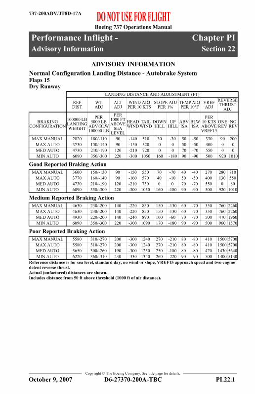
Boeing 737 Operations Manual
Performance Inflight - Chapter PIAdvisory Information Section 22
737-200ADV/JT8D-17A
FAST
-Doc
PI/P
D T
empl
ate
9/1/
99
Copyright © The Boeing Company. See title page for details.
PI.22 Performance Inflight --Advisory InformationADVISORY INFORMATIONAdvisory Information
Normal Configuration Landing Distance - Autobrake SystemFlaps 15Dry Runway
Good Reported Braking Action
Medium Reported Braking Action
Poor Reported Braking Action
LANDING DISTANCE AND ADJUSTMENT (FT)
REF DIST
WT ADJ
ALT ADJ
WIND ADJ PER 10 KTS
SLOPE ADJ PER 1%
TEMP ADJ PER 10°F
VREF ADJ
REVERSE THRUST
ADJ
BRAKING CONFIGURATION
100000 LB LANDING WEIGHT
PER 5000 LB
ABV/BLW 100000 LB
PER 1000 FT ABOVE
SEA LEVEL
HEAD WIND
TAIL WIND
DOWNHILL
UP HILL
ABV ISA
BLW ISA
PER 10 KTS ABOVE VREF15
ONE REV
NO REV
MAX MANUAL 2820 180/-110 90 -140 510 30 -30 50 -50 330 90 200MAX AUTO 3730 150/-140 90 -150 520 0 0 50 -50 400 0 0MED AUTO 4730 210/-190 120 -210 720 0 0 70 -70 550 0 0MIN AUTO 6090 350/-300 220 -300 1050 160 -180 90 -90 500 920 1010
MAX MANUAL 3600 150/-130 90 -150 550 70 -70 40 -40 270 280 710MAX AUTO 3770 160/-140 90 -160 570 40 -10 50 -50 400 130 550MED AUTO 4730 210/-190 120 -210 730 0 0 70 -70 550 0 80MIN AUTO 6090 350/-300 220 -300 1050 160 -180 90 -90 500 920 1010
MAX MANUAL 4630 230/-200 140 -220 850 150 -130 60 -70 350 760 2260MAX AUTO 4630 230/-200 140 -220 850 150 -130 60 -70 350 760 2260MED AUTO 4930 220/-200 140 -240 890 100 -60 70 -70 500 470 1960MIN AUTO 6090 350/-300 220 -300 1090 170 -180 90 -90 500 960 1570
MAX MANUAL 5580 310/-270 200 -300 1240 270 -210 80 -80 410 1500 5700MAX AUTO 5580 310/-270 200 -300 1240 270 -210 80 -80 410 1500 5700MED AUTO 5650 300/-260 190 -300 1250 250 -180 80 -80 470 1430 5640MIN AUTO 6220 360/-310 230 -330 1340 260 -220 90 -90 500 1400 5130
Reference distance is for sea level, standard day, no wind or slope, VREF15 approach speed and two engine detent reverse thrust.Actual (unfactored) distances are shown.Includes distance from 50 ft above threshold (1000 ft of air distance).
D6-27370-200A-TBC PI.22.1October 9, 2007

Boeing 737 Operations Manual
Performance Inflight -Advisory Information
737-200ADV/JT8D-17A
Copyright © The Boeing Company. See title page for details.
ADVISORY INFORMATIONAdvisory Information
Normal Configuration Landing Distance - Autobrake SystemFlaps 30Dry Runway
Good Reported Braking Action
Medium Reported Braking Action
Poor Reported Braking Action
LANDING DISTANCE AND ADJUSTMENT (FT)
REF DIST
WT ADJ
ALT ADJ
WIND ADJ PER 10 KTS
SLOPE ADJ PER 1%
TEMP ADJ PER 10°F
VREF ADJ
REVERSE THRUST
ADJ
BRAKING CONFIGURATION
100000 LB LANDING WEIGHT
PER 5000 LB
ABV/BLW 100000 LB
PER 1000 FT ABOVE
SEA LEVEL
HEAD WIND
TAIL WIND
DOWNHILL
UP HILL
ABV ISA
BLW ISA
PER 10 KTS ABOVE VREF30
ONE REV
NO REV
MAX MANUAL 2560 170/-80 80 -100 520 30 -30 40 -40 330 60 140MAX AUTO 3410 140/-120 80 -140 490 0 0 40 -40 370 0 0MED AUTO 4290 200/-170 110 -200 680 0 0 60 -60 510 0 0MIN AUTO 5430 300/-260 190 -280 980 150 -160 70 -80 420 800 930
MAX MANUAL 3350 140/-120 80 -150 530 70 -60 40 -40 270 250 620MAX AUTO 3450 140/-120 80 -150 540 50 -20 40 -40 360 140 520MED AUTO 4290 200/-170 110 -200 680 0 0 60 -60 510 0 70MIN AUTO 5430 300/-260 190 -280 980 150 -160 70 -80 420 800 930
MAX MANUAL 4230 200/-180 130 -210 810 140 -120 60 -60 330 640 1910MAX AUTO 4230 200/-180 130 -210 810 140 -120 60 -60 330 640 1910MED AUTO 4460 210/-180 120 -220 840 100 -50 60 -70 470 410 1670MIN AUTO 5440 300/-260 190 -280 1020 160 -160 70 -80 420 840 1410
MAX MANUAL 5030 270/-230 170 -280 1180 240 -190 70 -70 370 1250 4650MAX AUTO 5030 270/-230 170 -280 1180 240 -190 70 -70 370 1250 4650MED AUTO 5080 270/-230 170 -280 1190 220 -160 70 -70 420 1190 4600MIN AUTO 5560 320/-270 200 -310 1270 230 -200 80 -80 420 1230 4240
Reference distance is for sea level, standard day, no wind or slope, VREF30 approach speed and two engine detent reverse thrust.Actual (unfactored) distances are shown.Includes distance from 50 ft above threshold (1000 ft of air distance).
PI.22.2 D6-27370-200A-TBC October 9, 2007

Boeing 737 Operations Manual
Performance Inflight -Advisory Information
737-200ADV/JT8D-17A
Copyright © The Boeing Company. See title page for details.
ADVISORY INFORMATIONAdvisory Information
Normal Configuration Landing Distance - Autobrake SystemFlaps 40Dry Runway
Good Reported Braking Action
Medium Reported Braking Action
Poor Reported Braking Action
LANDING DISTANCE AND ADJUSTMENT (FT)
REF DIST
WT ADJ
ALT ADJ
WIND ADJ PER 10 KTS
SLOPE ADJ PER 1%
TEMP ADJ PER 10°F
VREF ADJ
REVERSE THRUST
ADJ
BRAKING CONFIGURATION
100000 LB LANDING WEIGHT
PER 5000 LB
ABV/BLW 100000 LB
PER 1000 FT ABOVE
SEA LEVEL
HEAD WIND
TAIL WIND
DOWNHILL
UP HILL
ABV ISA
BLW ISA
PER 10 KTS ABOVE VREF40
ONE REV
NO REV
MAX MANUAL 2480 160/-70 80 -90 510 30 -20 40 -30 320 50 120MAX AUTO 3300 130/-120 80 -140 480 0 0 40 -40 370 0 0MED AUTO 4140 180/-160 100 -190 660 0 0 60 -60 490 0 0MIN AUTO 5120 270/-240 170 -270 950 150 -150 70 -70 370 750 970
MAX MANUAL 3250 130/-110 80 -140 520 70 -60 40 -40 260 230 580MAX AUTO 3350 130/-120 80 -150 530 50 -20 40 -40 350 140 490MED AUTO 4140 180/-160 100 -190 670 0 0 60 -60 490 0 70MIN AUTO 5120 270/-240 170 -270 950 150 -150 70 -70 370 750 970
MAX MANUAL 4050 190/-170 120 -200 790 130 -110 50 -60 310 590 1730MAX AUTO 4050 190/-160 120 -200 790 130 -110 50 -60 310 590 1730MED AUTO 4280 190/-170 110 -220 830 90 -40 60 -60 470 370 1510MIN AUTO 5130 270/-240 170 -270 990 160 -160 70 -70 370 780 1400
MAX MANUAL 4770 250/-210 160 -270 1150 220 -170 70 -70 340 1120 4100MAX AUTO 4770 250/-210 160 -270 1150 220 -170 70 -70 340 1120 4100MED AUTO 4830 240/-210 150 -270 1160 200 -150 70 -70 380 1060 4040MIN AUTO 5240 280/-250 180 -300 1230 230 -190 70 -80 370 1140 3810
Reference distance is for sea level, standard day, no wind or slope, VREF40 approach speed and two engine detent reverse thrust.Actual (unfactored) distances are shown.Includes distance from 50 ft above threshold (1000 ft of air distance).
D6-27370-200A-TBC PI.22.3October 9, 2007

Boeing 737 Operations Manual
Performance Inflight -Advisory Information
737-200ADV/JT8D-17A
Copyright © The Boeing Company. See title page for details.
ADVISORY INFORMATIONAdvisory Information
Normal Configuration Landing Distance - Digital Autobrake SystemFlaps 15Dry Runway
Good Reported Braking Action
Medium Reported Braking Action
Poor Reported Braking Action
LANDING DISTANCE AND ADJUSTMENT (FT)
REF DIST
WT ADJ
ALT ADJ
WIND ADJ PER 10 KTS
SLOPE ADJ PER 1%
TEMP ADJ PER 10°F
VREF ADJ
REVERSE THRUST
ADJ
BRAKING CONFIGURATION
100000 LB LANDING WEIGHT
PER 5000 LB
ABV/BLW 100000 LB
PER 1000 FT ABOVE
SEA LEVEL
HEAD WIND
TAIL WIND
DOWNHILL
UP HILL
ABV ISA
BLW ISA
PER 10 KTS ABOVE VREF15
ONE REV
NO REV
MAX MANUAL 2820 180/-110 90 -140 510 30 -30 50 -50 330 90 200MAX AUTO 3840 150/-140 90 -150 520 10 -10 50 -50 380 0 0MED AUTO 5380 250/-240 150 -250 840 40 -70 80 -80 530 50 50MIN AUTO 6170 350/-310 230 -310 1080 200 -200 90 -90 470 1070 1250
MAX MANUAL 3600 150/-130 90 -150 550 70 -70 40 -40 270 280 710MAX AUTO 3890 160/-140 90 -160 580 40 -20 50 -50 380 170 630MED AUTO 5380 250/-240 150 -250 840 40 -70 80 -80 530 50 50MIN AUTO 6170 350/-310 230 -310 1080 200 -200 90 -90 470 1070 1250
MAX MANUAL 4630 230/-200 140 -220 850 150 -130 60 -70 350 760 2260MAX AUTO 4680 230/-200 150 -220 850 150 -130 60 -70 350 770 2290MED AUTO 5450 260/-250 160 -260 960 80 -90 80 -80 530 280 1610MIN AUTO 6170 350/-310 230 -310 1110 210 -210 90 -90 470 1100 1710
MAX MANUAL 5580 310/-270 200 -300 1240 270 -210 80 -80 410 1500 5700MAX AUTO 5590 310/-270 200 -300 1240 270 -210 80 -80 410 1500 5710MED AUTO 5830 310/-280 200 -310 1270 240 -180 80 -90 470 1270 5490MIN AUTO 6280 360/-320 240 -330 1350 280 -240 90 -90 470 1500 5160
Reference distance is for sea level, standard day, no wind or slope, VREF15 approach speed and two engine detent reverse thrust.Actual (unfactored) distances are shown.Includes distance from 50 ft above threshold (1000 ft of air distance).
PI.22.4 D6-27370-200A-TBC October 9, 2007

Boeing 737 Operations Manual
Performance Inflight -Advisory Information
737-200ADV/JT8D-17A
Copyright © The Boeing Company. See title page for details.
ADVISORY INFORMATIONAdvisory Information
Normal Configuration Landing Distance - Digital Autobrake SystemFlaps 30Dry Runway
Good Reported Braking Action
Medium Reported Braking Action
Poor Reported Braking Action
LANDING DISTANCE AND ADJUSTMENT (FT)
REF DIST
WT ADJ
ALT ADJ
WIND ADJ PER 10 KTS
SLOPE ADJ PER 1%
TEMP ADJ PER 10°F
VREF ADJ
REVERSE THRUST
ADJ
BRAKING CONFIGURATION
100000 LB LANDING WEIGHT
PER 5000 LB
ABV/BLW 100000 LB
PER 1000 FT ABOVE
SEA LEVEL
HEAD WIND
TAIL WIND
DOWNHILL
UP HILL
ABV ISA
BLW ISA
PER 10 KTS ABOVE VREF30
ONE REV
NO REV
MAX MANUAL 2560 170/-80 80 -100 520 30 -30 40 -40 330 60 140MAX AUTO 3500 140/-120 80 -140 490 10 -10 40 -40 350 0 0MED AUTO 4830 230/-210 130 -230 790 40 -60 70 -70 480 50 50MIN AUTO 5480 310/-260 190 -290 1010 180 -170 80 -80 410 910 1130
MAX MANUAL 3350 140/-120 80 -150 530 70 -60 40 -40 270 250 620MAX AUTO 3560 140/-130 80 -150 550 50 -30 40 -40 340 180 580MED AUTO 4830 230/-210 130 -230 790 40 -60 70 -70 480 50 60MIN AUTO 5480 310/-260 190 -290 1010 180 -170 80 -80 410 910 1130
MAX MANUAL 4230 200/-180 130 -210 810 140 -120 60 -60 330 640 1910MAX AUTO 4260 210/-180 130 -210 810 140 -110 60 -60 330 650 1930MED AUTO 4890 240/-210 140 -240 910 80 -80 70 -70 480 260 1380MIN AUTO 5480 310/-260 190 -290 1040 190 -170 80 -80 410 940 1530
MAX MANUAL 5030 270/-230 170 -280 1180 240 -190 70 -70 370 1250 4650MAX AUTO 5030 270/-230 170 -280 1180 240 -190 70 -70 370 1250 4660MED AUTO 5230 270/-240 170 -290 1210 220 -160 70 -80 420 1070 4480MIN AUTO 5590 320/-270 200 -310 1270 250 -210 80 -80 410 1290 4270
Reference distance is for sea level, standard day, no wind or slope, VREF30 approach speed and two engine detent reverse thrust.Actual (unfactored) distances are shown.Includes distance from 50 ft above threshold (1000 ft of air distance).
D6-27370-200A-TBC PI.22.5October 9, 2007
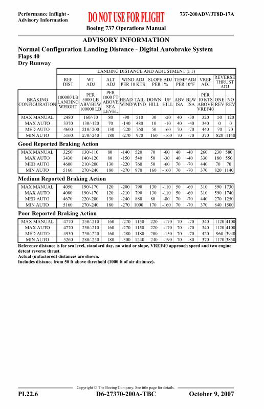
Boeing 737 Operations Manual
Performance Inflight -Advisory Information
737-200ADV/JT8D-17A
Copyright © The Boeing Company. See title page for details.
ADVISORY INFORMATIONAdvisory Information
Normal Configuration Landing Distance - Digital Autobrake SystemFlaps 40Dry Runway
Good Reported Braking Action
Medium Reported Braking Action
Poor Reported Braking Action
LANDING DISTANCE AND ADJUSTMENT (FT)
REF DIST
WT ADJ
ALT ADJ
WIND ADJ PER 10 KTS
SLOPE ADJ PER 1%
TEMP ADJ PER 10°F
VREF ADJ
REVERSE THRUST
ADJ
BRAKING CONFIGURATION
100000 LB LANDING WEIGHT
PER 5000 LB
ABV/BLW 100000 LB
PER 1000 FT ABOVE
SEA LEVEL
HEAD WIND
TAIL WIND
DOWNHILL
UP HILL
ABV ISA
BLW ISA
PER 10 KTS ABOVE VREF40
ONE REV
NO REV
MAX MANUAL 2480 160/-70 80 -90 510 30 -20 40 -30 320 50 120MAX AUTO 3370 130/-120 70 -140 480 10 -10 40 -40 340 0 0MED AUTO 4600 210/-200 130 -220 760 50 -60 70 -70 440 70 70MIN AUTO 5160 270/-240 180 -270 970 160 -160 70 -70 370 820 1140
MAX MANUAL 3250 130/-110 80 -140 520 70 -60 40 -40 260 230 580MAX AUTO 3430 140/-120 80 -150 540 50 -30 40 -40 330 180 550MED AUTO 4600 210/-200 130 -220 760 50 -60 70 -70 440 70 70MIN AUTO 5160 270/-240 180 -270 970 160 -160 70 -70 370 820 1140
MAX MANUAL 4050 190/-170 120 -200 790 130 -110 50 -60 310 590 1730MAX AUTO 4080 190/-170 120 -210 790 130 -110 50 -60 310 590 1740MED AUTO 4670 220/-200 130 -240 880 80 -80 70 -70 440 270 1250MIN AUTO 5160 270/-240 180 -270 1000 170 -160 70 -70 370 840 1500
MAX MANUAL 4770 250/-210 160 -270 1150 220 -170 70 -70 340 1120 4100MAX AUTO 4770 250/-210 160 -270 1150 220 -170 70 -70 340 1120 4100MED AUTO 4950 250/-220 160 -280 1180 200 -150 70 -70 420 960 3940MIN AUTO 5260 280/-250 180 -300 1240 240 -190 70 -80 370 1170 3850
Reference distance is for sea level, standard day, no wind or slope, VREF40 approach speed and two engine detent reverse thrust.Actual (unfactored) distances are shown.Includes distance from 50 ft above threshold (1000 ft of air distance).
PI.22.6 D6-27370-200A-TBC October 9, 2007

Boeing 737 Operations Manual
Performance Inflight -Advisory Information
737-200ADV/JT8D-17A
Copyright © The Boeing Company. See title page for details.
ADVISORY INFORMATIONAdvisory Information
Non-Normal Configuration Landing DistanceDry Runway
LANDING DISTANCE AND ADJUSTMENT (FT)REF DIST
FOR 100000 LB LANDING WEIGHT
WT ADJ PER
5000 LB ABV/BLW 100000 LB
ALT ADJ PER
1000 FTABOVE
SEA LEVEL
WIND ADJ PER 10 KTS
SLOPE ADJ PER 1%
APPROACH SPEED
LANDING CONFIGURATION VREF HEAD
WINDTAIL
WINDDOWN HILL
UP HILL
PER 10 KTS ABOVE VREF
ALL FLAPS UP VREF40+55 4400 370 / -210 440 -200 810 60 -60 420ANTI-SKID
INOPERATIVE VREF40 3640 135 / -120 75 -160 560 60 -55 275
HYDRAULICS- LOSS OF
SYSTEM A (FLAPS 15)
VREF15 3400 220 / -150 190 -170 620 60 -50 440
HYDRAULICS- LOSS OF
SYSTEM B (FLAPS 15)
VREF15 3100 190 / -130 130 -150 570 40 -40 360
HYDRAULICS- MANUAL
REVERSION (LOSS OF BOTH SYSTEM A & B)
VREF15 3850 260 / -170 230 -200 710 80 -70 530
STABILIZER TRIM
INOPERATIVEVREF15 2800 170 / -110 150 -140 500 30 -30 310
JAMMED OR RESTRICTED
FLIGHTCONTROLS
VREF15 2800 170 / -110 150 -140 500 30 -30 310
LEADING EDGE FLAPS TRANSIT VREF15+5 3050 190 / -130 180 -160 520 40 -40 320
ONE ENGINE INOPERATIVE VREF15 2850 190 / -120 160 -150 540 40 -30 350
TRAILING EDGE FLAP
ASYMMETRY(1≤ FLAPS <15)
VREF40+30 3700 260 / -180 290 -160 640 50 -40 330
TRAILING EDGE FLAPS UP
(FLAPS < 1)VREF40+40 3400 220 / -170 230 -150 570 40 -40 300
Reference distance assumes sea level, standard day, with no wind or slope.Actual (unfactored) distances are shown.Includes distance from 50 ft above runway threshold (1000 ft of air distance).Assumes maximum manual braking and maximum reverse thrust when available on operating engine(s).
D6-27370-200A-TBC PI.22.7October 9, 2007

Boeing 737 Operations Manual
Performance Inflight -Advisory Information
737-200ADV/JT8D-17A
Copyright © The Boeing Company. See title page for details.
ADVISORY INFORMATIONAdvisory Information
Non-Normal Configuration Landing DistanceGood Reported Braking Action
LANDING DISTANCE AND ADJUSTMENT (FT)REF DIST
FOR 100000 LB LANDING WEIGHT
WT ADJ PER
5000 LB ABV/BLW 100000 LB
ALT ADJ PER
1000 FTABOVE
SEA LEVEL
WIND ADJ PER 10 KTS
SLOPE ADJ PER 1%
APPROACH SPEED
LANDING CONFIGURATION VREF HEAD
WINDTAIL
WINDDOWN HILL
UP HILL
PER 10 KTS ABOVE VREF
ALL FLAPS UP VREF40+55 4900 170 / -170 410 -180 630 80 -80 280ANTI-SKID
INOPERATIVE VREF40 4270 180 / -155 105 -215 800 115 -90 305
HYDRAULICS- LOSS OF
SYSTEM A (FLAPS 15)
VREF15 4000 160 / -150 210 -170 590 90 -80 350
HYDRAULICS- LOSS OF
SYSTEM B (FLAPS 15)
VREF15 3620 150 / -130 150 -150 540 70 -60 280
HYDRAULICS- MANUAL
REVERSION(LOSS OF BOTH SYSTEM A & B)
VREF15 4200 190 / -160 230 -170 610 100 -90 400
STABILIZER TRIM
INOPERATIVEVREF15 3500 140 / -120 170 -150 530 60 -60 250
JAMMED ORRESTRICTED
FLIGHTCONTROLS
VREF15 3500 140 / -120 170 -150 530 60 -60 250
LEADING EDGE FLAPS TRANSIT VREF15+5 3750 160 / -130 200 -160 550 70 -70 290
ONE ENGINE INOPERATIVE VREF15 3750 150 / -140 190 -160 580 80 -80 290
TRAILING EDGE FLAP
ASYMMETRY(1≤ FLAPS <15)
VREF40+30 4300 160 / -150 290 -160 580 70 -70 250
TRAILING EDGE FLAPS UP
(FLAPS < 1)VREF40+40 4050 150 / -100 250 -160 560 70 -60 250
Reference distance assumes sea level, standard day, with no wind or slope.Actual (unfactored) distances are shown.Includes distance from 50 ft above runway threshold (1000 ft of air distance).Assumes maximum manual braking and maximum reverse thrust when available on operating engine(s).
PI.22.8 D6-27370-200A-TBC October 9, 2007

Boeing 737 Operations Manual
Performance Inflight -Advisory Information
737-200ADV/JT8D-17A
Copyright © The Boeing Company. See title page for details.
ADVISORY INFORMATIONAdvisory Information
Non-Normal Configuration Landing DistanceMedium Reported Braking Action
LANDING DISTANCE AND ADJUSTMENT (FT)REF DIST
FOR 100000 LB LANDING WEIGHT
WT ADJ PER
5000 LB ABV/BLW 100000 LB
ALT ADJ PER
1000 FTABOVE
SEA LEVEL
WIND ADJ PER 10 KTS
SLOPE ADJ PER 1%
APPROACH SPEED
LANDING CONFIGURATION VREF HEAD
WINDTAIL
WINDDOWN HILL
UP HILL
PER 10 KTS ABOVE VREF
ALL FLAPS UP VREF40+55 6200 280 / -240 530 -260 940 160 -150 360ANTI-SKID
INOPERATIVE VREF40 4880 225 / -195 135 -280 1135 265 -145 330
HYDRAULICS- LOSS OF
SYSTEM A (FLAPS 15)
VREF15 4950 230 / -210 260 -230 870 150 -140 400
HYDRAULICS- LOSS OF
SYSTEM B (FLAPS 15)
VREF15 4510 210 / -190 190 -220 820 130 -110 340
HYDRAULICS- MANUAL
REVERSION(LOSS OF BOTH SYSTEM A & B)
VREF15 5150 250 / -220 290 -240 890 170 -150 450
STABILIZER TRIM
INOPERATIVEVREF15 4400 200 / -180 220 -210 800 120 -110 310
JAMMED ORRESTRICTED
FLIGHTCONTROLS
VREF15 4400 200 / -180 220 -210 800 120 -110 310
LEADING EDGE FLAPS TRANSIT VREF15+5 4730 230 / -190 260 -220 840 140 -120 350
ONE ENGINE INOPERATIVE VREF15 5000 240 / -210 270 -250 940 190 -160 390
TRAILING EDGE FLAP
ASYMMETRY(1≤ FLAPS <15)
VREF40+30 5450 240 / -210 380 -230 870 140 -120 320
TRAILING EDGE FLAPS UP
(FLAPS < 1)VREF40+40 5100 230 / -200 320 -230 850 130 -120 320
Reference distance assumes sea level, standard day, with no wind or slope.Actual (unfactored) distances are shown.Includes distance from 50 ft above runway threshold (1000 ft of air distance).Assumes maximum manual braking and maximum reverse thrust when available on operating engine(s).
D6-27370-200A-TBC PI.22.9October 9, 2007

Boeing 737 Operations Manual
Performance Inflight -Advisory Information
737-200ADV/JT8D-17A
Copyright © The Boeing Company. See title page for details.
ADVISORY INFORMATIONAdvisory Information
Non-Normal Configuration Landing DistancePoor Reported Braking Action
LANDING DISTANCE AND ADJUSTMENT (FT)REF DIST
FOR 100000 LB LANDING WEIGHT
WT ADJ PER
5000 LB ABV/BLW 100000 LB
ALT ADJ PER
1000 FTABOVE
SEA LEVEL
WIND ADJ PER 10 KTS
SLOPE ADJ PER 1%
APPROACH SPEED
LANDING CONFIGURATION VREF HEAD
WINDTAIL
WINDDOWN HILL
UP HILL
PER 10 KTS ABOVE VREF
ALL FLAPS UP VREF40+55 7400 360 / -330 650 -340 1330 270 -230 410ANTI-SKID
INOPERATIVE VREF40 5630 280 / -245 170 -390 1865 1140 -265 350
HYDRAULICS- LOSS OF
SYSTEM A (FLAPS 15)
VREF15 5700 310 / -250 310 -300 1230 250 -210 430
HYDRAULICS- LOSS OF
SYSTEM B (FLAPS 15)
VREF15 5290 280 / -240 220 -290 1180 220 -180 380
HYDRAULICS- MANUAL
REVERSION (LOSS OF BOTH SYSTEM A & B)
VREF15 5950 320 / -280 340 -310 1250 260 -220 470
STABILIZER TRIM
INOPERATIVEVREF15 5150 270 / -230 260 -280 1160 210 -170 350
JAMMED ORRESTRICTED
FLIGHTCONTROLS
VREF15 5150 270 / -230 260 -280 1160 210 -170 350
LEADING EDGE FLAPS TRANSIT VREF15+5 5570 300 / -250 310 -300 1200 230 -190 400
ONE ENGINE INOPERATIVE VREF15 6300 330 / -300 340 -360 1430 380 -300 460
TRAILING EDGE FLAP
ASYMMETRY(1≤ FLAPS <15)
VREF40+30 6450 310 / -280 460 -310 1250 240 -200 370
TRAILING EDGE FLAPS UP
(FLAPS < 1)VREF40+40 6080 300 / -260 390 -300 1220 230 -190 370
Reference distance assumes sea level, standard day, with no wind or slope.Actual (unfactored) distances are shown.Includes distance from 50 ft above runway threshold (1000 ft of air distance).Assumes maximum manual braking and maximum reverse thrust when available on operating engine(s).
PI.22.10 D6-27370-200A-TBC October 9, 2007

Boeing 737 Operations Manual
Performance Inflight -Advisory Information
737-200ADV/JT8D-17A
Copyright © The Boeing Company. See title page for details.
ADVISORY INFORMATIONAdvisory Information
Brake Cooling ScheduleReference Brake Energy (Millions of Foot Pounds)
Adjusted Brake Energy per Brake (Millions of Foot Pounds)
Cooling Time (Minutes)
BRAKES ON SPEED (KIAS)60 80 100 120 140
WEIGHT (1000 LB)
OAT (°F)
PRESS ALT PRESS ALT PRESS ALT PRESS ALT PRESS ALT0 2 4 0 2 4 0 2 4 0 2 4 0 2 4
13040 4.8 5.2 5.7 8.5 9.2 9.9 13.0 14.1 15.3 18.3 19.9 21.5 22.2 24.0 25.980 5.2 5.7 6.1 9.2 10.0 10.7 14.1 15.3 16.5 19.8 21.4 23.2 23.9 25.9 27.9
120 5.6 6.1 6.6 9.9 10.7 11.5 15.1 16.4 17.7 21.2 23.0 24.9 25.7 27.8 30.0
12040 4.5 4.9 5.3 7.9 8.6 9.2 12.0 13.0 14.0 15.8 17.2 18.6 20.4 22.2 24.080 4.9 5.3 5.8 8.6 9.3 10.0 12.9 14.0 15.2 17.0 18.6 20.0 22.0 24.0 25.9
120 5.2 5.7 6.2 9.2 10.0 10.8 13.8 15.1 16.3 18.3 19.9 21.5 23.6 25.7 27.8
11040 4.2 4.5 4.9 7.2 7.8 8.5 11.1 12.1 13.0 15.1 16.5 17.8 18.5 20.1 21.780 4.5 4.9 5.3 7.8 8.5 9.2 12.0 13.0 14.1 16.3 17.8 19.2 20.0 21.7 23.4
120 4.8 5.2 5.6 8.4 9.1 9.9 12.8 14.0 15.2 17.5 19.0 20.6 21.4 23.3 25.2
10040 3.9 4.2 4.5 6.6 7.1 7.7 10.0 10.9 11.8 13.5 14.7 15.8 16.8 18.2 19.780 4.2 4.5 4.9 7.1 7.7 8.3 10.8 11.8 12.7 14.6 15.8 17.0 18.1 19.6 21.2
120 4.5 4.9 5.2 7.6 8.3 9.0 11.6 12.6 13.6 15.7 17.0 18.3 19.4 21.1 22.7
9040 3.4 3.7 4.0 6.0 6.5 7.1 9.0 9.7 10.5 11.8 12.8 13.8 14.8 16.1 17.480 3.6 4.0 4.3 6.5 7.0 7.6 9.7 10.5 11.4 12.7 13.8 14.9 16.0 17.4 18.8
120 3.9 4.2 4.6 6.9 7.5 8.2 10.4 11.3 12.2 13.6 14.9 16.1 17.2 18.7 20.2
8040 3.1 3.4 3.7 5.2 5.7 6.2 7.9 8.6 9.2 10.0 10.9 11.8 13.0 14.1 15.380 3.3 3.6 3.9 5.6 6.1 6.6 8.5 9.3 10.0 10.8 11.8 12.7 14.1 15.3 16.5
120 3.6 3.9 4.2 6.0 6.6 7.1 9.2 10.0 10.8 11.6 12.6 13.6 15.1 16.4 17.7To correct for wind, enter table with the brakes on speed minus one half the headwind or plus 1.5 times the tailwind.If ground speed is used for brakes on speed, ignore wind, altitude, and OAT effects.
REFERENCE BRAKE ENERGY PER BRAKE (MILLIONS OF FOOT POUNDS)EVENT 2 4 6 8 10 12 14 16 18 20
RTO MAX MAN 2 4 6 8 10 12 14 16 18 20MAX AUTO 1.8 3.5 5.3 7.1 8.7 10.2 11.7 13.1 14.4 15.7MED AUTO 1.5 3.2 4.8 6.3 7.6 8.8 10.0 10.8 11.7 12.5MIN AUTO 1.4 3.0 4.0 4.9 5.8 6.2 6.6 7.5 7.5 7.6
ADJUSTED BRAKE ENERGY PER BRAKE (MILLIONS OF FOOT POUNDS)6 & BELOW 8 10 12 14 15.9 16 TO 20 20 & ABOVE
INFLIGHT GEAR DOWN
NO SPECIAL PROCEDURE REQUIRED
1.0 2.9 4.9 7.0 8.8 CAUTION FUSE PLUG MELT ZONEGROUND 15 28 38 48 56
Observe maximum quick turnaround limit. Table does not consider the benefit of reverse thrust.Table shows energy per brake added by a single stop with all brakes operating. Energy is assumed to be equally distributed among the operating brakes. Total energy is the sum of residual energy plus energy added. Add 1.0 million foot pounds for each taxi mile. When in caution zone, wheel fuse plugs may melt. Delay takeoff and inspect after 30 minutes. If overheat occurs after takeoff, extend gear soon for at least 9 minutes. When in fuse plug melt zone, clear runway immediately. Unless required, do not set parking brake. Do not approach gear or attempt to taxi for 50 minutes. Alert fire equipment.
D6-27370-200A-TBC PI.22.11October 9, 2007

Boeing 737 Operations Manual
Performance Inflight -Advisory Information
737-200ADV/JT8D-17A
Copyright © The Boeing Company. See title page for details.
IntentionallyBlank
PI.22.12 D6-27370-200A-TBC October 9, 2007

Boeing 737 Operations Manual
Performance Inflight - Chapter PIEngine Inoperative Section 23
737-200ADV/JT8D-17A
FAST
-Doc
PI/P
D T
empl
ate
9/1/
99
Copyright © The Boeing Company. See title page for details.
PI.23 Performance Inflight --Engine InoperativeENGINE INOPEngine Inoperative
Max Continuous EPRBased on engine bleed for packs on, engine and wing anti-ice off
EPR Adjustments for Engine Bleeds
TAT (°C)
PRESSURE ALTITUDE (FT)0 1000 1499 1500 2000 3000 10000 15000 35000
50 1.79 1.79 1.79 1.79 1.79 1.79 1.78 1.78 1.7745 1.84 1.84 1.84 1.84 1.85 1.85 1.84 1.84 1.8340 1.87 1.87 1.87 1.90 1.90 1.90 1.89 1.89 1.8835 1.87 1.87 1.87 1.95 1.95 1.95 1.94 1.94 1.9330 1.92 1.92 1.92 2.00 2.00 2.00 1.99 1.99 1.9825 1.98 1.98 1.98 2.05 2.05 2.05 2.04 2.04 2.0220 2.03 2.03 2.03 2.10 2.10 2.10 2.09 2.09 2.0815 2.08 2.08 2.08 2.14 2.14 2.14 2.14 2.13 2.1210 2.13 2.13 2.13 2.19 2.19 2.19 2.18 2.17 2.165 2.13 2.18 2.18 2.20 2.23 2.23 2.22 2.21 2.200 2.13 2.18 2.20 2.20 2.23 2.26 2.25 2.25 2.24-5 2.13 2.18 2.20 2.20 2.23 2.27 2.28 2.28 2.27-10 2.13 2.18 2.20 2.20 2.23 2.27 2.31 2.31 2.30-15 2.13 2.18 2.20 2.20 2.23 2.27 2.31 2.33 2.32-20 2.13 2.18 2.20 2.20 2.23 2.27 2.31 2.33 2.32-25 2.13 2.18 2.20 2.20 2.23 2.27 2.31 2.33 2.32
-40TO-50 2.13 2.18 2.20 2.20 2.23 2.27 2.31 2.33 2.32
BLEED CONFIGURATION
PRESSURE ALTITUDE (FT)0 35000
PACKS OFF 0.03 0.03ENGINE ANTI-ICE ON -0.08 -0.08
ENGINE AND WING ANTI-ICE ON -0.15 -0.15With Gravel Protect switch in “Anti-Ice/Test” position and up to 15000 ft, decrease limit EPR by 0.01.With Gravel Protect switch in “Anti-Ice/Test” position and above 15000 ft, decrease limit EPR by 0.02.
D6-27370-200A-TBC PI.23.1April 5, 2002

Boeing 737 Operations Manual
Performance Inflight -Engine Inoperative
737-200ADV/JT8D-17A
Copyright © The Boeing Company. See title page for details.
ENGINE INOPMAX CONTINUOUS THRUST
Driftdown Speed/Level Off Altitude100 ft/min residual rate of climb
Driftdown/LRC Cruise Range CapabilityGround to Air Miles Conversion
Driftdown/Cruise Fuel and Time
WEIGHT (1000 LB) OPTIMUM DRIFTDOWN
SPEED (KIAS)
LEVEL OFF ALTITUDE (FT)START DRIFT DOWN
LEVEL OFF
ISA + 10°C & BELOW ISA + 15°C ISA + 20°C
130 123 231 14800 13700 12400120 113 223 17500 16500 15400110 104 214 20200 19300 18500100 95 204 22900 22200 2150090 86 194 25500 25100 2460080 76 183 28100 28000 2790070 67 171 31000 31000 3100060 57 158 34200 34200 34200
AIR DISTANCE (NM) GROUND DISTANCE
(NM)
AIR DISTANCE (NM)HEAD WIND COMPONENT (KTS) TAIL WIND COMPONENT (KTS)
100 80 60 40 20 20 40 60 80 100291 267 246 229 213 200 188 178 168 160 152577 530 490 456 426 400 377 356 338 321 306859 791 733 682 639 600 566 535 508 483 4611139 1050 974 908 851 800 755 715 679 646 6171417 1308 1215 1134 1063 1000 944 895 850 809 7721697 1567 1456 1359 1275 1200 1134 1074 1021 972 9281978 1827 1698 1585 1487 1400 1323 1254 1191 1135 10832262 2089 1941 1812 1699 1600 1512 1432 1361 1296 12382551 2355 2186 2040 1913 1800 1700 1610 1530 1457 1390
AIR DIST (NM)
FUEL REQUIRED (1000 LB) TIME
(HR:MIN)WEIGHT AT START OF DRIFTDOWN (1000 LB)70 80 90 100 110 120 130
200 2.0 2.1 2.3 2.7 2.9 3.2 3.4 0:38400 4.1 4.6 5.1 5.8 6.5 7.1 7.7 1:14600 6.1 6.9 7.7 8.7 9.7 10.5 11.4 1:49800 8.1 9.1 10.2 11.4 12.7 13.8 15.0 2:231000 10.0 11.3 12.6 14.1 15.6 17.0 18.5 2:571200 11.9 13.4 15.0 16.8 18.5 20.2 21.9 3:311400 13.7 15.5 17.3 19.3 21.3 23.3 25.3 4:051600 15.5 17.5 19.6 21.8 24.1 26.3 28.5 4:411800 17.3 19.5 21.8 24.3 26.8 29.2 31.7 5:18
Includes APU fuel burn. Driftdown at optimum driftdown speed and cruise at LRC speed.
PI.23.2 D6-27370-200A-TBC April 5, 2002

Boeing 737 Operations Manual
Performance Inflight -Engine Inoperative
737-200ADV/JT8D-17A
Copyright © The Boeing Company. See title page for details.
ENGINE INOPMAX CONTINUOUS THRUST
Long Range Cruise Altitude Capability100 ft/min residual rate of climb
Long Range Cruise Control
WEIGHT (1000 LB)
PRESSURE ALTITUDE (FT)ISA + 10°C & BELOW ISA + 15°C ISA + 20°C
130 9000 6900 3000120 12600 10700 8500110 16100 14300 12600100 19500 18200 1650090 23000 21900 2070080 26300 25600 2470070 29400 29200 2880060 32400 32300 32100
WEIGHT (1000 LB)
PRESSURE ALTITUDE (1000 FT)10 13 15 17 19 21 23 25 27 29 31
130
EPR 2.04 2.15MACH .541 .566KIAS 300 297
FF/ENG 6928 6970
120
EPR 1.95 2.07 2.15 2.24MACH .519 .549 .566 .584KIAS 288 288 286 284
FF/ENG 6262 6352 6380 6463
110
EPR 1.87 1.98 2.07 2.15 2.23MACH .501 .527 .548 .564 .582KIAS 277 276 276 274 272
FF/ENG 5684 5708 5767 5792 5861
100
EPR 1.80 1.89 1.97 2.05 2.13 2.22MACH .487 .505 .523 .544 .562 .579KIAS 269 264 264 264 262 260
FF/ENG 5205 5108 5125 5186 5208 5271
90
EPR 1.73 1.81 1.87 1.94 2.03 2.11 2.20 2.30MACH .469 .489 .500 .517 .539 .557 .575 .601KIAS 259 256 252 251 251 250 248 249
FF/ENG 4729 4634 4561 4553 4611 4638 4690 4839
80
EPR 1.64 1.73 1.78 1.84 1.91 1.99 2.08 2.17 2.27MACH .447 .469 .482 .495 .509 .530 .551 .569 .593KIAS 247 245 242 240 237 237 237 235 235
FF/ENG 4253 4165 4092 4039 4000 4035 4079 4115 4232
70
EPR 1.56 1.63 1.69 1.74 1.81 1.87 1.94 2.03 2.12 2.21MACH .423 .444 .460 .473 .487 .500 .517 .540 .559 .578KIAS 234 232 231 228 227 223 222 223 221 219
FF/ENG 3784 3698 3648 3579 3532 3479 3476 3526 3553 3600
60
EPR 1.48 1.54 1.58 1.64 1.69 1.75 1.82 1.90 1.98 2.07 2.17MACH .395 .417 .431 .446 .461 .475 .491 .511 .532 .555 .579KIAS 218 217 216 215 214 212 210 210 210 210 210
FF/ENG 3305 3235 3183 3133 3091 3030 3003 3013 3039 3074 3131
D6-27370-200A-TBC PI.23.3April 5, 2002

Boeing 737 Operations Manual
Performance Inflight -Engine Inoperative
737-200ADV/JT8D-17A
Copyright © The Boeing Company. See title page for details.
ENGINE INOPMAX CONTINUOUS THRUST
Long Range Cruise Diversion Fuel and TimeGround to Air Miles Conversion
Reference Fuel and Time Required at Check Point
Fuel Required Adjustment (1000 LB)
AIR DISTANCE (NM) GROUND DISTANCE
(NM)
AIR DISTANCE (NM)HEADWIND COMPONENT (KTS) TAILWIND COMPONENT (KTS)
100 80 60 40 20 20 40 60 80 100303 276 252 232 215 200 190 181 173 166 159615 557 506 465 431 400 380 362 345 330 317930 841 764 700 647 600 570 542 517 494 4741248 1127 1022 936 864 800 759 722 689 658 6311570 1415 1281 1172 1080 1000 949 902 860 822 7871896 1706 1542 1408 1298 1200 1139 1082 1031 984 9432227 2000 1805 1646 1515 1400 1328 1262 1202 1147 10982562 2298 2070 1886 1734 1600 1517 1441 1371 1309 12532902 2598 2336 2126 1952 1800 1706 1620 1542 1471 1408
AIR DIST (NM)
PRESSURE ALTITUDE (1000 FT)10 16 20 24 28
FUEL (1000 LB)
TIME (HR:MIN)
FUEL (1000 LB)
TIME (HR:MIN)
FUEL (1000 LB)
TIME (HR:MIN)
FUEL (1000 LB)
TIME (HR:MIN)
FUEL (1000 LB)
TIME (HR:MIN)
200 3.3 0:43 2.8 0:41 2.5 0:40 2.4 0:38 2.2 0:37400 6.5 1:24 5.7 1:20 5.3 1:16 5.1 1:13 4.9 1:09600 9.7 2:06 8.5 1:59 8.0 1:53 7.6 1:48 7.4 1:41800 12.9 2:48 11.4 2:38 10.7 2:30 10.2 2:23 10.0 2:14
1000 16.0 3:31 14.1 3:18 13.3 3:08 12.7 2:59 12.4 2:481200 19.1 4:15 16.9 3:58 15.9 3:46 15.2 3:34 14.8 3:221400 22.1 4:59 19.6 4:39 18.4 4:25 17.6 4:11 17.1 3:561600 25.0 5:44 22.2 5:20 20.8 5:05 19.9 4:48 19.4 4:311800 28.0 6:30 24.8 6:02 23.2 5:45 22.2 5:26 21.6 5:07
REFERENCE FUEL REQUIRED (1000 LB)
WEIGHT AT CHECK POINT (1000 LB)70 80 90 100 110 120
5 -0.4 -0.2 0.0 0.4 0.8 1.510 -0.9 -0.4 0.0 0.9 1.9 3.215 -1.3 -0.7 0.0 1.4 2.9 4.720 -1.8 -0.9 0.0 1.9 3.9 6.225 -2.2 -1.1 0.0 2.4 4.9 7.630 -2.7 -1.4 0.0 2.9 5.8 8.9
PI.23.4 D6-27370-200A-TBC April 5, 2002

Boeing 737 Operations Manual
Performance Inflight -Engine Inoperative
737-200ADV/JT8D-17A
Copyright © The Boeing Company. See title page for details.
ENGINE INOPMAX CONTINUOUS THRUST
HoldingFlaps Up
WEIGHT (1000 LB)
PRESSURE ALTITUDE (FT)1500 5000 10000 15000 20000 25000 30000
130EPR 1.65 1.76 1.95 2.17KIAS 243 246 246 247
FF/ENG 6110 6090 6150 6440
120EPR 1.59 1.69 1.87 2.08KIAS 232 236 236 237
FF/ENG 5630 5590 5590 5780
110EPR 1.54 1.62 1.78 1.98 2.22KIAS 220 223 227 227 228
FF/ENG 5160 5110 5070 5150 5430
100EPR 1.48 1.56 1.70 1.88 2.10KIAS 210 211 216 216 217
FF/ENG 4710 4640 4580 4580 4750
90EPR 1.43 1.50 1.62 1.78 1.99 2.23KIAS 210 210 210 210 210 210
FF/ENG 4340 4260 4160 4110 4170 4430
80EPR 1.39 1.45 1.56 1.70 1.88 2.10KIAS 210 210 210 210 210 210
FF/ENG 4020 3940 3830 3760 3750 3880
70EPR 1.35 1.40 1.50 1.62 1.79 1.99 2.24KIAS 210 210 210 210 210 210 210
FF/ENG 3740 3660 3560 3470 3420 3480 3660
60EPR 1.32 1.37 1.45 1.57 1.71 1.90 2.12KIAS 210 210 210 210 210 210 210
FF/ENG 3510 3430 3320 3230 3160 3160 3250This table includes 5% additional fuel for holding in a racetrack pattern.
D6-27370-200A-TBC PI.23.5April 5, 2002

Boeing 737 Operations Manual
Performance Inflight -Engine Inoperative
737-200ADV/JT8D-17A
Copyright © The Boeing Company. See title page for details.
IntentionallyBlank
PI.23.6 D6-27370-200A-TBC April 5, 2002

Boeing 737 Operations Manual
Performance Inflight - Chapter PIGear Down Section 24
737-200ADV/JT8D-17A
FAST
-Doc
PI/P
D T
empl
ate
9/1/
99
Copyright © The Boeing Company. See title page for details.
PI.24 Performance Inflight --Gear DownGEAR DOWNGear Down
220 KIAS Cruise Altitude CapabilityMax Cruise Thrust, 100 ft/min residual rate of climb
220 KIAS Cruise Control
WEIGHT (1000 LB)
PRESSURE ALTITUDE (FT)ISA + 10°C & BELOW ISA + 15°C ISA + 20°C
130 19200 17600 15500120 21100 19700 17900110 22700 21700 20100100 24200 23300 2220090 25500 24700 2370080 26600 25900 2500070 27600 27000 2620060 28400 27800 27200
WEIGHT (1000 LB)
PRESSURE ALTITUDE (1000 FT)10 13 15 17 19 21 23 25 27
130
EPR 1.72 1.83 1.91 1.99 2.09MACH .399 .422 .438 .456 .474KIAS 220 220 220 220 220
FF/ENG 4495 4489 4510 4569 4649
120
EPR 1.68 1.78 1.85 1.93 2.02 2.12MACH .399 .422 .438 .456 .474 .493KIAS 220 220 220 220 220 220
FF/ENG 4278 4257 4262 4291 4355 4435
110
EPR 1.64 1.73 1.80 1.88 1.96 2.05 2.15MACH .399 .422 .438 .456 .474 .493 .513KIAS 220 220 220 220 220 220 220
FF/ENG 4084 4052 4044 4057 4093 4161 4266
100
EPR 1.60 1.69 1.76 1.83 1.91 1.99 2.09 2.20MACH .399 .422 .438 .456 .474 .493 .513 .534KIAS 220 220 220 220 220 220 220 220
FF/ENG 3917 3877 3858 3858 3875 3924 4003 4129
90
EPR 1.57 1.65 1.72 1.79 1.86 1.94 2.04 2.14MACH .399 .422 .438 .456 .474 .493 .513 .534KIAS 220 220 220 220 220 220 220 220
FF/ENG 3776 3732 3708 3696 3703 3732 3800 3894
80
EPR 1.55 1.62 1.69 1.75 1.82 1.90 1.99 2.09 2.20MACH .399 .422 .438 .456 .474 .493 .513 .534 .557KIAS 220 220 220 220 220 220 220 220 220
FF/ENG 3659 3612 3585 3566 3562 3580 3634 3710 3828
70
EPR 1.53 1.60 1.66 1.72 1.79 1.87 1.95 2.05 2.15MACH .399 .422 .438 .456 .474 .493 .513 .534 .557KIAS 220 220 220 220 220 220 220 220 220
FF/ENG 3559 3510 3480 3457 3445 3456 3497 3562 3659
60
EPR 1.51 1.58 1.64 1.70 1.77 1.84 1.92 2.02 2.12MACH .399 .422 .438 .456 .474 .493 .513 .534 .557KIAS 220 220 220 220 220 220 220 220 220
FF/ENG 3480 3429 3398 3374 3355 3360 3392 3450 3531
D6-27370-200A-TBC PI.24.1April 5, 2002

Boeing 737 Operations Manual
Performance Inflight -Gear Down
737-200ADV/JT8D-17A
Copyright © The Boeing Company. See title page for details.
GEAR DOWNGear Down
220 KIAS Enroute Fuel and TimeGround to Air Miles Conversion
Reference Fuel and Time Required at Check Point
Fuel Required Adjustment (1000 LB)
Descent at 220 KIAS
AIR DISTANCE (NM) GROUND DISTANCE
(NM)
AIR DISTANCE (NM)HEADWIND COMPONENT (KTS) TAILWIND COMPONENT (KTS)
100 80 60 40 20 20 40 60 80 100335 297 264 239 218 200 189 179 170 161 154678 599 531 479 437 400 378 357 339 323 3081021 901 799 720 656 600 566 535 507 483 4611364 1204 1067 961 875 800 755 714 677 644 6141707 1506 1334 1201 1093 1000 943 892 845 804 7672050 1808 1602 1442 1312 1200 1132 1071 1015 964 9202393 2111 1871 1683 1531 1400 1321 1248 1183 1125 10742736 2413 2138 1923 1750 1600 1510 1427 1353 1286 12273079 2715 2406 2164 1969 1800 1698 1605 1521 1446 1380
AIR DIST (NM)
PRESSURE ALTITUDE (1000 FT)10 14 18 22 26
FUEL (1000 LB)
TIME (HR:MIN)
FUEL (1000 LB)
TIME (HR:MIN)
FUEL (1000 LB)
TIME (HR:MIN)
FUEL (1000 LB)
TIME (HR:MIN)
FUEL (1000 LB)
TIME (HR:MIN)
200 5.7 0:50 5.2 0:47 4.7 0:45 4.4 0:43 4.2 0:41400 11.5 1:37 10.5 1:32 9.8 1:27 9.2 1:22 9.0 1:18600 17.2 2:24 15.8 2:16 14.7 2:08 13.9 2:01 13.6 1:54800 22.8 3:11 21.1 3:00 19.6 2:50 18.5 2:40 18.1 2:31
1000 28.3 3:58 26.2 3:45 24.4 3:32 23.1 3:20 22.5 3:081200 33.8 4:45 31.3 4:29 29.1 4:13 27.6 3:59 26.9 3:441400 39.2 5:32 36.3 5:13 33.8 4:55 32.0 4:38 31.2 4:211600 44.6 6:20 41.3 5:58 38.4 5:37 36.4 5:17 35.5 4:581800 49.9 7:07 46.3 6:42 43.0 6:18 40.7 5:56 39.7 5:34
REFERENCE FUEL REQUIRED (1000 LB)
WEIGHT AT CHECK POINT (1000 LB)70 80 90 100 110 120
5 -0.2 -0.1 0.0 0.2 0.5 0.810 -0.5 -0.3 0.0 0.5 1.1 1.815 -0.7 -0.4 0.0 0.7 1.6 2.620 -0.9 -0.5 0.0 0.9 2.1 3.425 -1.1 -0.6 0.0 1.1 2.5 4.130 -1.2 -0.7 0.0 1.3 2.8 4.735 -1.4 -0.8 0.0 1.4 3.1 5.240 -1.5 -0.8 0.0 1.5 3.4 5.645 -1.5 -0.9 0.0 1.6 3.6 5.9
PRESSURE ALT (1000 FT) 5 10 15 17 19 21 23 25 27 29 31 33DISTANCE (NM) 19 28 37 41 45 49 52 56 60 64 67 71TIME (MINUTES) 7 9 11 12 13 14 14 15 16 16 17 18
PI.24.2 D6-27370-200A-TBC April 5, 2002

Boeing 737 Operations Manual
Performance Inflight -Gear Down
737-200ADV/JT8D-17A
Copyright © The Boeing Company. See title page for details.
GEAR DOWNGear Down
HoldingFlaps Up
WEIGHT (1000 LB)
PRESSURE ALTITUDE (FT)1500 5000 10000 15000 20000 25000
130EPR 1.55 1.64 1.80 2.00KIAS 243 246 246 247
FF/ENG 5330 5320 5260 5400
120EPR 1.49 1.58 1.73 1.91KIAS 232 236 236 237
FF/ENG 4890 4900 4830 4870
110EPR 1.44 1.52 1.66 1.83 2.04KIAS 220 223 227 227 228
FF/ENG 4470 4450 4430 4400 4540
100EPR 1.40 1.46 1.59 1.74 1.93 2.19KIAS 210 211 216 216 217 219
FF/ENG 4100 4030 4020 3960 4010 4310
90EPR 1.37 1.43 1.54 1.67 1.85 2.07KIAS 210 210 210 210 210 210
FF/ENG 3930 3840 3740 3660 3640 3770
80EPR 1.36 1.41 1.51 1.64 1.80 2.02KIAS 210 210 210 210 210 210
FF/ENG 3790 3700 3600 3520 3480 3560
70EPR 1.34 1.39 1.49 1.61 1.77 1.97KIAS 210 210 210 210 210 210
FF/ENG 3680 3590 3480 3400 3340 3400
60EPR 1.33 1.38 1.47 1.58 1.74 1.93KIAS 210 210 210 210 210 210
FF/ENG 3580 3490 3380 3300 3240 3270This table includes 5% additional fuel for holding in a racetrack pattern.
D6-27370-200A-TBC PI.24.3April 5, 2002

Boeing 737 Operations Manual
Performance Inflight -Gear Down
737-200ADV/JT8D-17A
Copyright © The Boeing Company. See title page for details.
IntentionallyBlank
PI.24.4 D6-27370-200A-TBC April 5, 2002

Boeing 737 Operations Manual
Performance Inflight - Chapter PIText Section 25
737-200ADV/JT8D-17A
FAST
-Doc
PI/P
D T
empl
ate
9/1/
99
Copyright © The Boeing Company. See title page for details.
PI.25 Performance Inflight --TextText
IntroductionThis chapter contains information required to complete a normal flight. Inthe event of conflict between data presented in this chapter and thatcontained in the Approved Flight Manual, the Flight Manual shall alwaystake precedence.
General
Takeoff SpeedsThe speeds presented in the Takeoff Speeds table can be used for allperformance conditions except where adjustments must be made to V1 forclearway, stopway, anti-skid inoperative, improved climb, contaminatedrunway situations or brake energy limitations. These speeds may be usedfor weights less than or equal to the performance limited weight.Normal takeoff speeds, V1, VR and V2, with anti-skid on, are read fromthe table by entering with station pressure altitude and moving horizontallyto the appropriate outside air temperature (OAT) column. Proceed downand read V1, VR and V2 for the anticipated takeoff weight and flap setting.Slope and wind adjustments to V1 are obtained by entering the V1Adjustments chart. Adjusted V1 must not exceed VR.
VMCGRegulations prohibit scheduling takeoff with a V1 less than minimum V1for control on the ground, VMCG. Therefore compare the adjusted V1 tothe VMCG. To find VMCG, enter the VMCG table with the airportpressure altitude and actual OAT. If VR is less than VMCG, set VR equalto VMCG, and determine a new V2 by adding the difference between thenormal VR and VMCG to the normal V2.
Clearway and Stopway V1 AdjustmentsTakeoff speed adjustments are to be applied to V1 speed when usingtakeoff weights based on the use of clearway and stopway. Adjust V1 speed by the amount shown in the appropriate column. Theadjusted V1 speed must not exceed VR.Maximum allowable clearway limits are provided for guidance when moreprecise data is not available.
D6-27370-200A-TBC PI.25.1October 8, 2004

Boeing 737 Operations Manual
Performance Inflight -Text
737-200ADV/JT8D-17A
Copyright © The Boeing Company. See title page for details.
Stab Trim To find takeoff stabilizer trim setting, enter the Stab Trim Setting tablewith takeoff flap setting and center of gravity (C.G. % MAC) and readrequired stabilizer trim units.
VREFThe Reference Speed table contains flaps 40, 30 and 15 landing speeds fora given weight. Apply wind adjustments shown as required.
Flap Maneuver SpeedsThis table provides the flap speed schedule for recommended maneuveringspeed. The speed schedule is a function of weight and will provideadequate maneuver margin above stall at all weights.During flap retraction/extension, movement of the flap to the next positionshould be initiated when reaching the maneuver speed for the existing flap.
Slush/Standing Water TakeoffExperience has shown that aircraft performance may deterioratesignificantly on runways covered with snow, slush, standing water or ice.Therefore, reductions in field/obstacle limited takeoff weight and revisedtakeoff speeds are necessary. The tables are intended for guidance inaccordance with advisory material and are based on all engines operatingthroughout the takeoff.The entire runway is assumed to be completely covered by a contaminantof uniform thickness and density. Therefore this information isconservative when operating under typical colder weather conditionswhere patches of slush exist and some degree of sanding is common.Takeoffs in slush/standing water depths greater than 0.50 inches (13 mm)are not recommended because of possible airplane damage as a result ofslush/standing water impingement on the airplane structure. The use ofassumed temperature method for reduced thrust is not allowed oncontaminated runways. Interpolation for slush/standing water depthsbetween the values shown is permitted.Takeoff weight determination:Instructions for Using Tables:1. Determine the dry field/obstacle limit weight for the anticipated flapsetting.2. Enter the Weight Adjustment table with the dry field/obstacle limitweight to obtain the slush/standing water weight adjustment for the slushdepth and airport pressure altitude.
PI.25.2 D6-27370-200A-TBC October 8, 2004
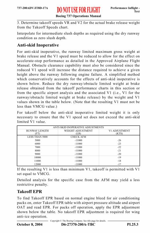
Boeing 737 Operations Manual
Performance Inflight -Text
737-200ADV/JT8D-17A
Copyright © The Boeing Company. See title page for details.
3. Determine takeoff speeds VR and V2 for the actual brake release weightfrom the Takeoff Speeds chart.Interpolate for intermediate slush depths as required using the dry runwaycondition as zero slush depth.
Anti-skid InoperativeFor anti-skid inoperative, the runway limited maximum gross weight atbrake release and the V1 speed must be reduced to allow for the effect onaccelerate-stop performance as detailed in the Approved Airplane FlightManual. Obstacle clearance capability must also be considered since thereduced V1 speed will increase the distance required to achieve a givenheight above the runway following engine failure. A simplified methodwhich conservatively accounts for the effects of anti-skid inoperative isshown below. Reduce the dry runway/obstacle limited weight at brakerelease obtained from the takeoff performance charts in this section orfrom the specific airport analysis and the associated V1 (i.e., V1 for therunway/obstacle limited weight at brake release) by the weight and V1values shown in the table below. (Note that the resulting V1 must not beless than VMCG value.)For takeoff below the anti-skid inoperative limited weight it is onlynecessary to ensure that the V1 speed set does not exceed the anti-skidlimited V1 value.
If the resulting V1 is less than minimum V1, takeoff is permitted with V1set equal to VMCG. Detailed analysis for the specific case from the AFM may yield a lessrestrictive penalty.
Takeoff EPRTo find Takeoff EPR based on normal engine bleed for air conditioningpacks on, enter Takeoff EPR table with airport pressure altitude and airportOAT and read EPR. For packs off operation, apply the EPR adjustmentshown below the table. No takeoff EPR adjustment is required for winganti-ice operation.
ANTI-SKID INOPERATIVE ADJUSTMENTSRUNWAY LENGTH
(FT)WEIGHT ADJUSTMENT
(LB)V1 ADJUSTMENT
(KTS)LESS THAN 5000 CHECK AFM
5000 -11000 -266000 -11000 -237000 -11000 -228000 -11000 -219000 -11000 -20
10000 -11000 -1911000 -11000 -1812000 -11000 -17
D6-27370-200A-TBC PI.25.3October 8, 2004

Boeing 737 Operations Manual
Performance Inflight -Text
737-200ADV/JT8D-17A
Copyright © The Boeing Company. See title page for details.
Reduced Takeoff EPRThe tables present the allowable Takeoff EPR Reduction as a function ofActual OAT and Surplus Weight which is defined as the differencebetween the Performance Limited TOGW and the Actual TOGW. Thesetables are valid for engine A/C bleed on or off, any flap setting. They arenot valid when the maximum takeoff weight is limited by obstacles, brakeenergy or tire speed. Since the tables are conservative, larger reductions inEPR may be achieved under some conditions by using the AssumedTemperature Method described in the AFM Appendix.Enter the Field Length Limited section of the table appropriate for theairplane pressure altitude with the Surplus Weight based on the field lengthlimit (i.e., Field length limited weight minus actual weight). Read theallowable Takeoff EPR Reduction. Then enter the Climb Limited sectionof the table with the Surplus Weight based on the climb limit anddetermine the allowable Takeoff EPR Reduction. Use the smaller of thetwo reductions. Enter the Minimum EPR table with the pressure altitude.The Takeoff EPR, after the reduction is applied, should not be less thanthis minimum. Apply the noted V1, VR and V2 adjustments.Takeoff with assumed temperature reduced thrust is not permitted when:runway is contaminated with water, ice, slush or snow; anti-skid isinoperative. Use of this procedure is not recommended if potentialwindshear conditions exist.
Max Climb EPRThis table shows Max Climb EPR based on normal engine bleed for packson and anti-ice off. Enter the table with pressure altitude and TAT andread EPR. EPR adjustments are shown for anti-ice operation.
Go-around EPRTo find Go-around EPR based on normal engine bleed for packs on andwing anti-ice off, enter the Go-around EPR table with airport pressurealtitude and reported OAT or TAT and read EPR. For packs off, apply theEPR adjustment shown below the table. EPR adjustments are also shownfor engine and wing anti-ice operations.
Flight with Unreliable Airspeed / Turbulent Air PenetrationPitch attitude and average EPR information is provided for use in allphases of flight in the event of unreliable airspeed/Mach indicationsresulting from blocking or freezing of the pitot system. Loss of radome orturbulent air may also cause unreliable airspeed/Mach indications. Thecruise table in this section may also be used for turbulent air penetration.
PI.25.4 D6-27370-200A-TBC October 3, 2003
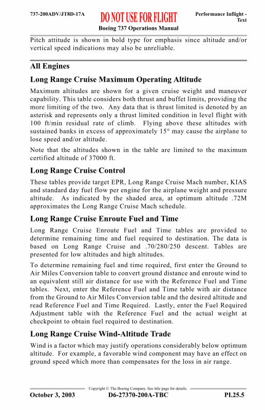
Boeing 737 Operations Manual
Performance Inflight -Text
737-200ADV/JT8D-17A
Copyright © The Boeing Company. See title page for details.
Pitch attitude is shown in bold type for emphasis since altitude and/orvertical speed indications may also be unreliable.
All Engines
Long Range Cruise Maximum Operating AltitudeMaximum altitudes are shown for a given cruise weight and maneuvercapability. This table considers both thrust and buffet limits, providing themore limiting of the two. Any data that is thrust limited is denoted by anasterisk and represents only a thrust limited condition in level flight with100 ft/min residual rate of climb. Flying above these altitudes withsustained banks in excess of approximately 15° may cause the airplane tolose speed and/or altitude.Note that the altitudes shown in the table are limited to the maximumcertified altitude of 37000 ft.
Long Range Cruise ControlThese tables provide target EPR, Long Range Cruise Mach number, KIASand standard day fuel flow per engine for the airplane weight and pressurealtitude. As indicated by the shaded area, at optimum altitude .72Mapproximates the Long Range Cruise Mach schedule.
Long Range Cruise Enroute Fuel and TimeLong Range Cruise Enroute Fuel and Time tables are provided todetermine remaining time and fuel required to destination. The data isbased on Long Range Cruise and .70/280/250 descent. Tables arepresented for low altitudes and high altitudes.To determine remaining fuel and time required, first enter the Ground toAir Miles Conversion table to convert ground distance and enroute wind toan equivalent still air distance for use with the Reference Fuel and Timetables. Next, enter the Reference Fuel and Time table with air distancefrom the Ground to Air Miles Conversion table and the desired altitude andread Reference Fuel and Time Required. Lastly, enter the Fuel RequiredAdjustment table with the Reference Fuel and the actual weight atcheckpoint to obtain fuel required to destination.
Long Range Cruise Wind-Altitude TradeWind is a factor which may justify operations considerably below optimumaltitude. For example, a favorable wind component may have an effect onground speed which more than compensates for the loss in air range.
D6-27370-200A-TBC PI.25.5October 3, 2003

Boeing 737 Operations Manual
Performance Inflight -Text
737-200ADV/JT8D-17A
Copyright © The Boeing Company. See title page for details.
Using this table, it is possible to determine the break-even wind (advantagenecessary or disadvantage that can be tolerated) to maintain the same rangeat another altitude and long range cruise speed. The tables make noallowance for climb or descent time, fuel or distance, and are based oncomparing ground fuel mileage.
DescentDistance and time for descent are shown for a .70/280/250 descent speedschedule. Enter the table with top of descent pressure altitude and readdistance in nautical miles and time in minutes. Data is based on flight idlethrust descent in zero wind. Allowances are included for a straight-inapproach with gear down and landing flaps at the outer marker.
HoldingTarget EPR, indicated airspeed and fuel flow per engine information istabulated for holding with flaps up based on the optimum holding speedschedule. This is the higher of the maximum endurance speed and themaneuvering speed. Small variations in airspeed will not appreciablyaffect the overall endurance time. Enter the table with weight and pressurealtitude to read EPR, KIAS and fuel flow per engine.
Advisory Information
Autobrake Landing DistanceThe Autobrake Landing Distance tables are provided as advisoryinformation to assist in the selection of the most desirable autobrakesetting for a given field length. It is not to be used to determine requiredfield length. This data reflects actual landing distances on a dry runway forsetting MINIMUM through MAXIMUM, from touchdown to full stop,with or without reverse thrust. The tables include typical flare distancesfrom threshold.To use the Autobrake Landing Distance table, determine the appropriatetable to use. The Digital Autobrake Landing Distance table is onlyapplicable if Autobrake Control Valve Module, Boeing part number60800263 is installed. Enter the chart with the estimated approach speedand determine the actual stopping distance from touchdown for a givenautobrake setting. If airspeed is used for approach speed, adjust landingdistance for pressure altitude and tailwind effects.Selection of an autobrake setting results in a constant rate of deceleration.Maximum effort manual braking should achieve shorter landing distancethan the MAXIMUM setting.
PI.25.6 D6-27370-200A-TBC October 3, 2003

Boeing 737 Operations Manual
Performance Inflight -Text
737-200ADV/JT8D-17A
Copyright © The Boeing Company. See title page for details.
Slippery Runway Landing DistanceLanding distances are the actual landing distances and do not include the1.67% regulatory factor. Therefore they cannot be used to determinedispatch required landing field length. When landing on slippery runwaysor runways contaminated with ice, snow, slush or standing water, thereported braking action must be considered. If the surface is affected bywater, snow or ice, and the braking action is reported as “good,” conditionsshould not be expected to be as good as on clean dry runways. The value“good” is comparative and is intended to mean that airplanes should notexperience braking or directional control difficulties when landing. Theperformance level used to calculate the “good” data is consistent with wetrunway testing done on early Boeing jets. The performance level used tocalculate the “poor” data reflects runways covered with wet ice. Readlanding distance for the reported braking action at the airplane weight, andthen apply the adjustments for airport pressure altitude and approach speedas required.
Non-normal Configuration Landing DistanceAdvisory information is provided to support non-normal configurationsthat affect landing performance of the airplane. Landing distances areshown for dry runway and good, medium and poor reported braking action.Each non-normal configuration is listed with its recommended approachspeed. Landing distance can be determined for the reference landingweight and then adjusted for actual weight and pressure altitude.
Brake Cooling ScheduleAdvisory information is provided to assist in avoiding the problemsassociated with hot brakes. For normal operation, most landings are atweights below the AFM quick turnaround limit weight.Use of the recommended cooling schedule will help avoid brake overheatand fuse plug problems that could result from repeated landings at shorttime intervals or a rejected takeoff.Enter the Brake Cooling Schedule table with the airplane weight andbrakes on speed, adjusted for wind at the appropriate temperature andaltitude condition. Instructions for applying wind adjustments are includedbelow the table. Linear interpolation may be used to obtain intermediatevalues. The resulting number is the reference brake energy per brake inmillions of foot-pounds, and represents the amount of energy absorbed byeach brake during a rejected takeoff.To determine the energy per brake absorbed during landing, enter theAdjusted Brake Energy Per Brake table with the reference brake energy perbrake and the type of braking used during landing (RTO Max Man, Max
D6-27370-200A-TBC PI.25.7April 7, 2006

Boeing 737 Operations Manual
Performance Inflight -Text
737-200ADV/JT8D-17A
Copyright © The Boeing Company. See title page for details.
Auto, Med Auto or Min Auto). The resulting number is the adjusted brakeenergy per brake and represents the energy absorbed in each brake duringthe landing.The recommended cooling time is found in the final table by entering withthe adjusted brake energy per brake. Times are provided for groundcooling and inflight gear down cooling.
Engine Inoperative
Max Continuous EPRPower setting is based on one engine operating with one A/C packoperating and all anti-ice bleeds off. Enter the table with pressure altitudeand TAT to read EPR.It is desirable to maintain engine thrust within the limits of the Max Cruisethrust rating. However, where thrust in excess of Max Cruise rating isrequired, such as for meeting terrain clearance, ATC altitude assignments,or to attain maximum range capability, it is permissible to use the thrustneeded up to the Max Continuous thrust rating. The Max Continuousthrust rating is intended primarily for emergency use at the discretion ofthe pilot and is the maximum thrust that may be used continuously.
Driftdown Speed/Level Off AltitudeThe table shows optimum driftdown speed as a function of cruise weightat start of driftdown. Also shown are the approximate weight and pressurealtitude at which the airplane will level off considering 100 ft/min residualrate of climb.The level off altitude is dependent on air temperature (ISA deviation).
Driftdown/LRC Range CapabilityThis table shows the range capability from the start of driftdown.Driftdown is continued to level off altitude. As weight decreases due tofuel burn, the airplane is accelerated to Long Range Cruise speed. Cruiseis continued at level off altitude and Long Range Cruise speed.To determine fuel required, enter the Ground to Air Miles Conversion tablewith the desired ground distance and adjust for anticipated winds to obtainair distance to destination. Then enter the Driftdown/Cruise Fuel and Timetable with air distance and weight at start of driftdown to determine fueland time required. If altitudes other than the level off altitude are used,fuel and time required may be obtained by using the Engine InoperativeLong Range Cruise Diversion Fuel and Time table.
PI.25.8 D6-27370-200A-TBC April 7, 2006

Boeing 737 Operations Manual
Performance Inflight -Text
737-200ADV/JT8D-17A
Copyright © The Boeing Company. See title page for details.
Long Range Cruise Altitude CapabilityThe table shows the maximum altitude that can be maintained at a givenweight and air temperature (ISA deviation), based on Long Range Cruisespeed, Max Continuous thrust, and 100 ft/min residual rate of climb.
Long Range Cruise ControlThe table provides target EPR, engine inoperative Long Range CruiseMach number, KIAS and fuel flow for the airplane weight and pressurealtitude. The fuel flow values in this table reflect single engine fuel burn.To conservatively account for APU fuel burn, add 115 kg/hr to fuel flowvalues.
Long Range Cruise Diversion Fuel and TimeTables are provided for crews to determine the fuel and time required toproceed to an alternate airfield with one engine inoperative. The data isbased on single engine Long Range Cruise speed and .70/280/250 descent.Enter with Air Distance as determined from the Ground to Air MilesConversion table and read Fuel and Time required at the cruise pressurealtitude. Adjust the fuel obtained for deviation from the reference weightat checkpoint as required by entering the Fuel Required Adjustment tablewith the fuel required for the reference weight and the actual weight atcheckpoint.
HoldingSingle engine holding data is provided in the same format as the all engineholding data and is based on the same assumptions.
Gear DownThis section contains performance for airplane operation with the landinggear extended for all phases of flight. The data is based on engine bleedsfor normal air conditioning.Note: The Flight Management Computer System (FMCS) does not containspecial provisions for operation with landing gear extended. As a result,the FMCS will generate inappropriate enroute speed schedules, displaynon-conservative predictions of fuel burn, estimated time of arrival (ETA),maximum altitude, and compute overly shallow descent path. An accurateestimated time of arrival (ETA) is available if current speed or Mach isentered into the VNAV cruise page.Tables for gear down performance in this section are identical in formatand used in the same manner as tables for the gear up configurationpreviously described.
D6-27370-200A-TBC PI.25.9April 3, 2007

Boeing 737 Operations Manual
Performance Inflight -Text
737-200ADV/JT8D-17A
Copyright © The Boeing Company. See title page for details.
IntentionallyBlank
PI.25.10 D6-27370-200A-TBC April 3, 2007

Boeing 737 Operations Manual
Performance Inflight - Chapter PIGeneral Section 30
737-200ADV/JT8D-9
FAST
-Doc
PI/P
D T
empl
ate
9/1/
99
Copyright © The Boeing Company. See title page for details.
PI.30 Performance Inflight --GeneralGeneral
Takeoff Speeds
158151144136128120153146139132124116150143136129122114138131124117110134127121113110125118110110
153145139131121113
142134126119110
139132124116107
125118110
131123116108105
113106105
105
151144136128120
139132124116
136129122114
124117110
121113110
111110
144136128120
139132124116
129122114
124117110
113110
111110
140132123114
127
111
125117108
119111105
109
107105
105
135
141133124115
136128120111
125117109
120112105
109105
107105
120
146139131122113
134126119110
133125117107
118111105
116108105
106105
148140132123114
135127119110
133125117108
119112105
116108105
106105
158151144136128120
146139132124116
143136129122114
131124117110134127121113110
118111110
155147140132123114
143135127119110
140132124116108
126119111105131123116108105
113106105
153145138130121112148141134126118109
138132123116106133125118110105130123115107105121113105105
158151144136128120153146139132124116
143136129122114138131124117110134127121
110125118110110
113
155147139131122113150142135126118109
139132124116107134126119111105130123115107105121113105105
151144137129120110146140133
117107144137131123115105132124117109
129122114106
120112
105105
105
105
125
153146138130121111148141134125117107145138131123115106133125118110105129122114106105120112
105105
152145138129121112147141133126117108145138131123115105132125117109105130122115107105120112105105
158151144136128120153146139132124116150143136129122114138131124117110134127121113110125118110110
154147139130122113149142134126117108146139131123115106133126118110105130122115107105120112105105
V1 ADJUSTMENTS
SUBTRACT 1 KT PER5 KTS TAILWIND
SUBTRACT 1 KT PER1% DOWN SLOPE
BOXED AREA INDICATES PERFORMANCE AFFECTED BY MINIMUM CONTROL SPEED,
PRESSUREALTITUDE1000 FT
°F°C°F°C°F°C°F°C°F°C°F°C
OAT
120110100 90 80 70120110100 90 80 70120110100 90 80 70110100 90 80 70110100 90 80 70100 90 80 70
ANTI-SKID ONV1, VR, V2
1
2
5
10
15
25
9 TO 10
7 TO 9
5 TO 7
3 TO 5
1 TO 3
-1 TO 1
WTFLAPS
WIND SLOPE
to
to
to 2 30 57 97 14 36
98 115 37 46
35 86
to
to
to
to 8 34-13 1 32 56 0 13
59 97 15 36100 115 38 46
to
to
to
to
to-21 7-29 -14 3 31-16 - 1
2 14 86 99 30 37102 115 39 46
35 58 12 34
41 85
to
to
to
to
to
to
-65 -22-54 -30
-24 2-31 -17
-11 1
5 29 89 101 32 38
40 46104 115
to
to
to
to
to-65 -25-54 -32
-19 11-28 -12 17 40- 8 4 48 88 9 31 93 103 34 39
-65 -20to
to
to
to
-54 -29-65 16-54 - 9-65 47-54 8-65 92-54 33
2VRVV12VRVV12VRVV12VRVV12VRVV12VRVV11000 LB
MINIMUM FIELD LENGTH FOR LIGHTEST WEIGHT ABOVE BOXED AREA IS REQUIRED.
D6-27370-200A-TBC PI.30.1April 5, 2002

Boeing 737 Operations Manual
Performance Inflight -General
737-200ADV/JT8D-9
Copyright © The Boeing Company. See title page for details.
General
VMCG
Clearway and Stopway V1 Adjustments
Maximum Allowable Clearway
Stab Trim SettingMax Takeoff Thrust
VREF (KIAS)
OAT (°C)
PRESSURE ALTITUDE (FT)0 2000 4000 6000 8000 10000
50 95 91 8840 99 95 92 88 8530 103 99 96 92 89 8520 103 100 96 92 89 8610 103 101 97 94 90 870 103 103 100 96 92 89
-10 103 103 102 98 94 91-20 103 103 104 100 96 93-30 103 103 104 102 98 94-40 103 103 104 103 100 96
CLEARWAY MINUS STOPWAY (FT)
NORMAL V1 (KIAS)100 120 140 160
900 -3 -3 -3 -3600 -2 -2 -2 -2300 -1 -1 -1 -10 0 0 0 0
-300 1 1 1 1-600 2 2 2 2-900 3 3 3 3
FIELD LENGTH (FT)
MAX ALLOWABLE CLEARWAY FOR V1
REDUCTION (FT)4000 4506000 6008000 70010000 800
C.G. %MAC 6 10 14 18 22 26 30 32FLAPS 1 THRU FLAPS 10 7 3/4 7 6 1/4 5 1/2 4 3/4 4 3 1/4 2 3/4
FLAPS 15 & FLAPS 25 8 3/4 7 3/4 7 6 5 4 3 1/4 2 3/4
WEIGHT (1000 LB)
FLAPS40 30 15
130 149 154 161125 146 150 158120 142 146 154115 139 142 150110 135 139 146105 132 135 142100 128 131 13895 124 127 13490 121 124 13185 117 120 12780 113 116 12375 110 112 11970 106 109 115
For approach speed add wind factor of 1/2 headwind component + gust (max 20 knots).
PI.30.2 D6-27370-200A-TBC April 5, 2002

Boeing 737 Operations Manual
Performance Inflight -General
737-200ADV/JT8D-9
Copyright © The Boeing Company. See title page for details.
General
Flap Maneuver Speeds
FLAP POSITION
MANEUVER SPEED (KIAS)WEIGHT
AT OR BELOW 117000 LB ABOVE 117000 LB AND AT OR BELOW 138500 LB ABOVE 138500 LB
UP 210 220 2301 190 200 2105 170 180 190
10 160 170 18015 150 160 17025 140 150 160
D6-27370-200A-TBC PI.30.3April 5, 2002

Boeing 737 Operations Manual
Performance Inflight -General
737-200ADV/JT8D-9
Copyright © The Boeing Company. See title page for details.
ALL ENGINESADVISORY INFORMATION
Slush/Standing Water TakeoffWeight Adjustment (1000 LB)
DRY FIELD/OBSTACLE
LIMIT WEIGHT (1000 LB)
SLUSH/STANDING WATER DEPTH0.25 INCHES (6 mm ) 0.50 INCHES (13 mm)
PRESS ALT (FT) PRESS ALT (FT)S.L. 4000 8000 S.L. 4000 8000
140 -10.0 -11.1 -12.4 -21.8 -25.6 -30.8130 -8.4 -10.6 -12.6 -19.2 -23.2 -29.2120 -7.3 -8.9 -11.1 -16.0 -20.0 -26.1110 -5.8 -7.3 -10.0 -12.5 -16.5 -22.5100 -4.5 -6.1 -8.7 -9.4 -13.0 -18.490 -3.7 -5.0 -6.4 -6.7 -9.5 -14.080 -2.0 -3.5 -4.2 -4.2 -5.9 -8.7
For flaps 10, 15 and 25 increase allowable weight limit on slush/standing water by 1000 lb (0.25 in) or 2000 lb (0.50 in).Interpolate as required using dry runway as zero slush/standing water depth.
PI.30.4 D6-27370-200A-TBC April 5, 2002

Boeing 737 Operations Manual
Performance Inflight -General
737-200ADV/JT8D-9
Copyright © The Boeing Company. See title page for details.
Takeoff EPRBased on engine bleed for packs on and anti-ice on or off
EPR Adjustments for Engine Bleeds
%N1 vs EPR Crosscheck(Takeoff and Go-around)
AIRPORT OAT AIRPORT PRESSURE ALTITUDE (FT)°F °C -1000 0 1000 2000 3000 4000 5000 5660 6000 7000 8000
120 49 1.82 1.82 1.82 1.82 1.82 1.82 1.82 1.82 1.82 1.82 1.82104 40 1.91 1.91 1.91 1.91 1.91 1.91 1.91 1.91 1.91 1.91 1.9195 35 1.95 1.95 1.95 1.95 1.95 1.95 1.95 1.95 1.95 1.95 1.9586 30 1.96 2.00 2.00 2.00 2.00 2.00 2.00 2.00 2.00 2.00 2.0077 25 1.96 2.01 2.01 2.01 2.01 2.01 2.01 2.01 2.01 2.01 2.0168 20 1.96 2.01 2.01 2.01 2.01 2.01 2.01 2.01 2.01 2.01 2.0159 15 1.96 2.01 2.01 2.01 2.01 2.01 2.01 2.01 2.01 2.01 2.0150 10 1.96 2.01 2.04 2.04 2.04 2.04 2.04 2.04 2.04 2.04 2.0441 5 1.96 2.01 2.06 2.07 2.07 2.07 2.07 2.07 2.07 2.07 2.0732 0 1.96 2.01 2.06 2.11 2.11 2.11 2.11 2.11 2.11 2.11 2.1123 -5 1.96 2.01 2.06 2.11 2.14 2.14 2.14 2.14 2.14 2.14 2.1414 -10 1.96 2.01 2.06 2.11 2.16 2.17 2.17 2.17 2.17 2.17 2.175 -15 1.96 2.01 2.06 2.11 2.16 2.19 2.19 2.19 2.19 2.19 2.19-4 -20 1.96 2.01 2.06 2.11 2.16 2.22 2.22 2.22 2.22 2.22 2.22-13 -25 1.96 2.01 2.06 2.11 2.16 2.22 2.24 2.24 2.24 2.24 2.24-22 -30 1.96 2.01 2.06 2.11 2.16 2.22 2.27 2.27 2.27 2.27 2.27-31 -35 1.96 2.01 2.06 2.11 2.16 2.22 2.27 2.29 2.29 2.29 2.29-40 -40 1.96 2.01 2.06 2.11 2.16 2.22 2.27 2.31 2.31 2.31 2.31-49 -45 1.96 2.01 2.06 2.11 2.16 2.22 2.27 2.31 2.31 2.31 2.31-65 -54 1.96 2.01 2.06 2.11 2.16 2.22 2.27 2.31 2.31 2.31 2.31
BLEED CONFIGURATION
AIRPORT PRESSURE ALTITUDE (FT)-1000 8000
PACKS OFF 0.03 0.03
AIRPORT OAT
TARGET %N1EPR
°F °C 1.70 1.80 1.90 2.00 2.10 2.20 2.30130 54 90 93 96 99 102 107 111122 50 89 92 95 98 102 106 110104 40 88 91 94 97 100 104 10886 30 87 90 92 95 99 102 10668 20 85 88 91 94 97 101 10550 10 84 87 89 92 95 99 10332 0 82 85 88 90 94 97 10114 -10 81 84 86 89 92 95 99-4 -20 79 82 84 87 90 94 97-22 -30 78 80 83 85 88 92 95-40 -40 76 78 81 84 87 90 94-58 -50 75 77 79 82 85 88 92-65 -54 74 76 78 81 84 87 91
Use scheduled Takeoff or Go-around EPR. Use actual OAT only. %N1 operating tolerance ±2%%N1 limit 102.45%A/C on or off For engine anti-icing on, increase %N1 by 1%.
D6-27370-200A-TBC PI.30.5April 5, 2002

Boeing 737 Operations Manual
Performance Inflight -General
737-200ADV/JT8D-9
Copyright © The Boeing Company. See title page for details.
Reduced Takeoff EPRBased on engine bleed for packs on or off1000 FT Pressure Altitude and BelowTakeoff EPR Reduction
Minimum EPR
FIELD LENGTH LIMITED
CLIMB LIMITED
(ALL TEMPS)SURPLUS WEIGHT
(LB)
OAT
°C-10 TO -6
-5 TO -1
0 TO 4
5 TO 9
10 TO 14
15 TO 19
20 TO 24
25 TO 29
30 TO 33
34 AND ABOVE
°F14 TO 22
23 TO 31
32 TO 40
41 TO 49
50 TO 58
59 TO 67
68 TO 76
77 TO 85
86 TO 92
93 AND ABOVE
1000 TO 1999 0.01 0.002000 TO 2999 0.01 0.03 0.013000 TO 3999 0.01 0.03 0.04 0.024000 TO 4999 0.02 0.03 0.04 0.06 0.035000 TO 5999 0.01 0.02 0.03 0.05 0.06 0.08 0.046000 TO 6999 0.01 0.03 0.04 0.05 0.06 0.08 0.10 0.057000 TO 7999 0.02 0.03 0.04 0.05 0.07 0.08 0.09 0.11 0.068000 TO 8999 0.02 0.03 0.05 0.06 0.07 0.08 0.10 0.11 0.13 0.079000 TO 9999 0.02 0.03 0.05 0.06 0.08 0.09 0.10 0.11 0.13 0.15 0.08
10000 TO 10999 0.04 0.05 0.07 0.08 0.09 0.10 0.12 0.13 0.14 0.16 0.0911000 TO 11999 0.05 0.07 0.08 0.10 0.11 0.12 0.13 0.15 0.16 0.18 0.1012000 TO 12999 0.07 0.08 0.10 0.11 0.13 0.14 0.15 0.16 0.18 0.20 0.1113000 TO 13999 0.09 0.10 0.12 0.13 0.14 0.16 0.17 0.18 0.19 0.21 0.1214000 TO 14999 0.10 0.12 0.13 0.15 0.16 0.17 0.18 0.20 0.21 0.23 0.1315000 TO 15999 0.12 0.14 0.15 0.16 0.18 0.19 0.20 0.21 0.23 0.25 0.1416000 TO 16999 0.14 0.15 0.17 0.18 0.19 0.21 0.22 0.23 0.24 0.26 0.1417000 TO 17999 0.15 0.17 0.18 0.20 0.21 0.22 0.24 0.25 0.26 0.28 0.1518000 TO 18999 0.17 0.19 0.20 0.21 0.23 0.24 0.25 0.27 0.28 0.30 0.1619000 TO 19999 0.19 0.20 0.22 0.23 0.24 0.26 0.27 0.28 0.29 0.30 0.1720000 TO 20999 0.20 0.22 0.23 0.25 0.26 0.27 0.29 0.30 0.30 0.30 0.1821000 TO 21999 0.22 0.24 0.25 0.26 0.28 0.29 0.30 0.30 0.30 0.30 0.1922000 TO 22999 0.24 0.25 0.27 0.28 0.29 0.30 0.30 0.30 0.30 0.30 0.2023000 TO 23999 0.25 0.27 0.28 0.30 0.30 0.30 0.30 0.30 0.30 0.30 0.2124000 TO 24999 0.27 0.29 0.30 0.30 0.30 0.30 0.30 0.30 0.30 0.30 0.2225000 TO 25999 0.29 0.30 0.30 0.30 0.30 0.30 0.30 0.30 0.30 0.30 0.2326000 TO 26779 0.30 0.30 0.30 0.30 0.30 0.30 0.30 0.30 0.30 0.30 0.2426780 TO 27859 0.30 0.30 0.30 0.30 0.30 0.30 0.30 0.30 0.30 0.30 0.2527860 TO 28929 0.30 0.30 0.30 0.30 0.30 0.30 0.30 0.30 0.30 0.30 0.2628930 TO 29999 0.30 0.30 0.30 0.30 0.30 0.30 0.30 0.30 0.30 0.30 0.2730000 TO 31069 0.30 0.30 0.30 0.30 0.30 0.30 0.30 0.30 0.30 0.30 0.2831070 TO 32149 0.30 0.30 0.30 0.30 0.30 0.30 0.30 0.30 0.30 0.30 0.29
32150 AND ABOVE 0.30 0.30 0.30 0.30 0.30 0.30 0.30 0.30 0.30 0.30 0.30
PRESSURE ALTITUDE (1000 FT)-1 0 1 2 3 4 5 6 7 8 9 10 11 12 13 13.5
1.82 1.82 1.82 1.82 1.83 1.85 1.86 1.88 1.90 1.92 1.99 2.01 2.01 2.01 2.01 2.01Increase Minimum EPR by 0.03 for bleeds off.Use actual weight and OAT to determine takeoff speeds. Increase V1 and VR by 1 kt for each 0.10 EPR reduction, except when speeds are found in shaded area of the Takeoff Speeds chart.If V1 prior to adjustment is found in the shaded area of the Takeoff Speeds chart, find the lightest weight above the shaded area and using the weight as the actual weight recalculate the surplus weight and the Takeoff EPR reduction.
PI.30.6 D6-27370-200A-TBC April 5, 2002

Boeing 737 Operations Manual
Performance Inflight -General
737-200ADV/JT8D-9
Copyright © The Boeing Company. See title page for details.
Reduced Takeoff EPRBased on engine bleed for packs on or offAbove 1000 FT Pressure AltitudeTakeoff EPR Reduction
Minimum EPR
FIELD LENGTH LIMITED
CLIMB LIMITED
(ALL TEMPS)SURPLUS WEIGHT
(LB)
OAT
°C-10 TO -6
-5 TO -1
0 TO 4
5 TO 9
10 TO 14
15 TO 19
20 TO 24
25 TO 29
30 TO 33
34 AND ABOVE
°F14 TO 22
23 TO 31
32 TO 40
41 TO 49
50 TO 58
59 TO 67
68 TO 76
77 TO 85
86 TO 92
93 AND ABOVE
1000 TO 1999 0.02 0.02 0.01 0.01 0.002000 TO 2999 0.02 0.04 0.02 0.03 0.02 0.013000 TO 3999 0.02 0.04 0.04 0.02 0.04 0.04 0.024000 TO 4999 0.02 0.04 0.04 0.05 0.03 0.06 0.05 0.035000 TO 5999 0.04 0.04 0.04 0.05 0.03 0.02 0.07 0.07 0.046000 TO 6999 0.04 0.05 0.05 0.05 0.03 0.01 0.02 0.04 0.09 0.08 0.057000 TO 7999 0.04 0.05 0.05 0.05 0.04 0.03 0.04 0.05 0.10 0.09 0.078000 TO 8999 0.05 0.05 0.05 0.06 0.06 0.05 0.05 0.07 0.12 0.11 0.089000 TO 9999 0.05 0.08 0.06 0.08 0.07 0.06 0.07 0.08 0.13 0.12 0.09
10000 TO 10999 0.05 0.06 0.08 0.10 0.09 0.07 0.08 0.10 0.14 0.14 0.1011000 TO 11999 0.06 0.08 0.09 0.11 0.10 0.09 0.10 0.11 0.16 0.15 0.1212000 TO 12999 0.08 0.10 0.11 0.13 0.12 0.10 0.11 0.12 0.17 0.16 0.1313000 TO 13999 0.10 0.11 0.12 0.14 0.13 0.12 0.13 0.14 0.19 0.18 0.1414000 TO 14999 0.11 0.13 0.14 0.16 0.14 0.13 0.14 0.15 0.20 0.19 0.1515000 TO 15999 0.12 0.14 0.15 0.17 0.16 0.14 0.15 0.17 0.22 0.21 0.1616000 TO 16999 0.14 0.16 0.17 0.18 0.17 0.16 0.17 0.18 0.23 0.22 0.1817000 TO 17999 0.15 0.17 0.18 0.20 0.19 0.17 0.18 0.19 0.24 0.23 0.1918000 TO 18999 0.17 0.18 0.19 0.21 0.20 0.19 0.20 0.21 0.26 0.25 0.2019000 TO 19999 0.18 0.20 0.21 0.23 0.21 0.20 0.21 0.22 0.27 0.26 0.2120000 TO 20999 0.20 0.21 0.22 0.24 0.23 0.21 0.22 0.24 0.29 0.28 0.2221000 TO 21999 0.21 0.23 0.24 0.25 0.24 0.23 0.24 0.25 0.30 0.29 0.2322000 TO 22999 0.22 0.24 0.25 0.27 0.26 0.24 0.25 0.26 0.30 0.30 0.2523000 TO 23999 0.24 0.25 0.26 0.28 0.27 0.26 0.27 0.28 0.30 0.30 0.2624000 TO 24999 0.25 0.27 0.28 0.30 0.29 0.27 0.28 0.29 0.30 0.30 0.2725000 TO 25999 0.27 0.28 0.29 0.30 0.30 0.29 0.30 0.30 0.30 0.30 0.2826000 TO 26999 0.28 0.30 0.30 0.30 0.30 0.30 0.30 0.30 0.30 0.30 0.29
27000 AND ABOVE 0.30 0.30 0.30 0.30 0.30 0.30 0.30 0.30 0.30 0.30 0.30
PRESSURE ALTITUDE (1000 FT)-1 0 1 2 3 4 5 6 7 8 9 10 11 12 13 13.5
1.82 1.82 1.82 1.82 1.83 1.85 1.86 1.88 1.90 1.92 1.99 2.01 2.01 2.01 2.01 2.01Increase Minimum EPR by 0.03 for bleeds off.Use actual weight and OAT to determine takeoff speeds. Increase V1 and VR by 1 kt for each 0.10 EPR reduction, except when speeds are found in shaded area of the Takeoff Speeds chart.If V1 prior to adjustment is found in the shaded area of the Takeoff Speeds chart, find the lightest weight above the shaded area and using the weight as the actual weight recalculate the surplus weight and the Takeoff EPR reduction.
D6-27370-200A-TBC PI.30.7April 5, 2002

Boeing 737 Operations Manual
Performance Inflight -General
737-200ADV/JT8D-9
Copyright © The Boeing Company. See title page for details.
Max Climb EPRBased on engine bleed for packs on and anti-ice off
EPR Adjustments for Engine Bleeds
TAT (°C)
PRESSURE ALTITUDE (1000 FT)/SPEED (KIAS OR MACH)0 1 2 3 4 5.66 10 15 20 25 30 35 37
320 320 320 320 320 320 320 320 320 .70 .70 .70 .7050 1.64 1.64 1.64 1.64 1.64 1.64 1.64 1.64 1.64 1.64 1.6445 1.67 1.67 1.67 1.67 1.67 1.67 1.67 1.67 1.67 1.67 1.6740 1.70 1.70 1.70 1.70 1.70 1.70 1.70 1.70 1.70 1.70 1.7035 1.73 1.73 1.73 1.73 1.73 1.73 1.73 1.73 1.73 1.73 1.7330 1.76 1.76 1.76 1.76 1.76 1.76 1.76 1.76 1.76 1.76 1.7625 1.79 1.79 1.79 1.79 1.79 1.79 1.79 1.79 1.79 1.79 1.7920 1.82 1.82 1.82 1.82 1.82 1.82 1.82 1.82 1.82 1.82 1.8215 1.86 1.86 1.86 1.86 1.86 1.86 1.86 1.86 1.86 1.86 1.8610 1.90 1.90 1.90 1.90 1.90 1.90 1.90 1.90 1.90 1.90 1.905 1.94 1.94 1.94 1.94 1.94 1.94 1.94 1.94 1.94 1.94 1.94 1.92 1.920 1.99 1.99 1.99 1.99 1.99 1.99 1.99 1.99 1.99 1.99 1.99 1.97 1.97-5 1.98 2.04 2.04 2.04 2.04 2.04 2.04 2.04 2.04 2.04 2.04 2.02 2.02-10 1.98 2.04 2.09 2.09 2.09 2.09 2.09 2.09 2.09 2.09 2.09 2.07 2.07-15 1.98 2.04 2.09 2.12 2.12 2.12 2.12 2.12 2.12 2.12 2.12 2.11 2.11-20 1.98 2.04 2.09 2.14 2.15 2.15 2.15 2.15 2.15 2.15 2.15 2.14 2.14-25 1.98 2.04 2.09 2.14 2.18 2.18 2.18 2.18 2.18 2.18 2.18 2.17 2.17-30 1.98 2.04 2.09 2.14 2.20 2.21 2.21 2.21 2.21 2.21 2.21 2.20 2.20-35 1.98 2.04 2.09 2.14 2.20 2.23 2.23 2.23 2.23 2.23 2.23 2.22 2.22-40 1.98 2.04 2.09 2.14 2.20 2.25 2.25 2.25 2.25 2.25 2.25 2.24 2.24
BLEED CONFIGURATION
PRESSURE ALTITUDE (FT)0 37000
PACKS OFF 0.04 0.04ENGINE ANTI-ICE ON -0.08 -0.08
ENGINE AND WING ANTI-ICE ON* -0.04 -0.04ENGINE AND WING ANTI-ICE ON** -0.06 -0.06
*Dual Bleed Source**Single Bleed Source
PI.30.8 D6-27370-200A-TBC April 5, 2002

Boeing 737 Operations Manual
Performance Inflight -General
737-200ADV/JT8D-9
Copyright © The Boeing Company. See title page for details.
Go-around EPRBased on engine bleed for packs on, wing anti-ice off
EPR Adjustments for Engine Bleeds
REPORTED OAT TAT (°C)
AIRPORT PRESSURE ALTITUDE (FT)°F °C -1000 0 1000 2000 3000 4000 5000 5660 6000 8000
119 48 50 1.80 1.80 1.80 1.80 1.80 1.80 1.80 1.80 1.80 1.80100 38 40 1.90 1.90 1.90 1.90 1.90 1.90 1.90 1.90 1.90 1.9091 33 35 1.93 1.94 1.94 1.94 1.94 1.94 1.94 1.94 1.94 1.9483 28 30 1.93 1.98 1.98 1.98 1.98 1.98 1.98 1.98 1.98 1.9873 23 25 1.93 1.98 1.98 1.98 1.98 1.98 1.98 1.98 1.98 1.9864 18 20 1.93 1.98 1.98 1.98 1.98 1.98 1.98 1.98 1.98 1.9855 13 15 1.93 1.98 2.00 2.00 2.00 2.00 2.00 2.00 2.00 2.0047 8 10 1.93 1.98 2.04 2.04 2.04 2.04 2.04 2.04 2.04 2.0438 3 5 1.93 1.98 2.04 2.07 2.07 2.07 2.07 2.07 2.07 2.0727 -3 0 1.93 1.98 2.04 2.09 2.10 2.10 2.10 2.10 2.10 2.1018 -8 -5 1.93 1.98 2.04 2.09 2.13 2.13 2.13 2.13 2.13 2.1310 -13 -10 1.93 1.98 2.04 2.09 2.15 2.16 2.16 2.16 2.16 2.160 -18 -15 1.93 1.98 2.04 2.09 2.15 2.19 2.19 2.19 2.19 2.19
-10 -23 -20 1.93 1.98 2.04 2.09 2.15 2.20 2.21 2.21 2.21 2.21-17 -27 -25 1.93 1.98 2.04 2.09 2.15 2.20 2.24 2.24 2.24 2.24-25 -32 -30 1.93 1.98 2.04 2.09 2.15 2.20 2.26 2.26 2.26 2.26-36 -37 -35 1.93 1.98 2.04 2.09 2.15 2.20 2.26 2.29 2.29 2.29-43 -42 -40 1.93 1.98 2.04 2.09 2.15 2.20 2.26 2.30 2.30 2.30-52 -47 -45 1.93 1.98 2.04 2.09 2.15 2.20 2.26 2.30 2.30 2.30-61 -52 -50 1.93 1.98 2.04 2.09 2.15 2.20 2.26 2.30 2.30 2.30
BLEED CONFIGURATION
AIRPORT PRESSURE ALTITUDE (FT)-1000 8000
A/C PACKS OFF 0.03 0.03ENGINE ANTI-ICE ON 0 0
ENGINE AND WING ANTI-ICE ON* -0.04 -0.04ENGINE AND WING ANTI-ICE ON** -0.06 -0.06
*Dual Bleed Source**Single Bleed Source
D6-27370-200A-TBC PI.30.9April 5, 2002

Boeing 737 Operations Manual
Performance Inflight -General
737-200ADV/JT8D-9
Copyright © The Boeing Company. See title page for details.
Flight With Unreliable Airspeed / Turbulent Air PenetrationAltitude and/or vertical speed indications may also be unreliable.Climb (280/.70)Flaps Up, Set Max Climb Thrust
Cruise (.70/280)Flaps Up, EPR for Level Flight
Descent (.70/280)Flaps Up, Set Idle Thrust
HoldingFlaps Up, EPR for Level Flight
PRESSURE ALTITUDE (FT)
WEIGHT (1000 LB)80 100 120
35000 PITCH ATT 6.0 6.0V/S (FT/MIN) 1300 600
30000 PITCH ATT 6.0 6.0 6.0V/S (FT/MIN) 2000 1300 700
27000 PITCH ATT 6.0 6.0 6.0V/S (FT/MIN) 2100 1500 1000
25000 PITCH ATT 5.0 5.0 6.0V/S (FT/MIN) 1900 1400 900
20000 PITCH ATT 6.0 6.0 6.0V/S (FT/MIN) 2600 1800 1300
15000 PITCH ATT 7.0 7.0 7.0V/S (FT/MIN) 2900 2100 1700
5000 PITCH ATT 10.0 9.0 8.0V/S (FT/MIN) 3900 2900 2300
SEA LEVEL PITCH ATT 11.0 10.0 9.0V/S (FT/MIN) 4500 3500 2700
PRESSURE ALTITUDE (FT)
WEIGHT (1000 LB)80 90 100 110
30000 PITCH ATT 2.8 3.4 3.9 4.4EPR 1.68 1.71 1.78 1.84
10000 PITCH ATT 2.2 2.6 3.0 3.4EPR 1.31 1.33 1.35 1.37
PRESSURE ALTITUDE (FT)
WEIGHT (1000 LB)80 90 100
30000 PITCH ATT -0.8 -0.3 0.5V/S (FT/MIN) -2500 -2400 -2300
10000 PITCH ATT -1.9 -1.2 -0.6V/S (FT/MIN) -2300 -2200 -2000
PRESSURE ALTITUDE (FT)
WEIGHT (1000 LB)80 90 100 110
10000PITCH ATT 4.8 4.8 4.8 4.8
EPR 1.22 1.26 1.29 1.33KIAS 210 225 235 245
PI.30.10 D6-27370-200A-TBC April 5, 2002

Boeing 737 Operations Manual
Performance Inflight -General
737-200ADV/JT8D-9
Copyright © The Boeing Company. See title page for details.
Flight With Unreliable Airspeed / Turbulent Air PenetrationAltitude and/or vertical speed indications may also be unreliable.Terminal Area (0 to 10000 FT)EPR for Level Flight
Final Approach (0 to 10000 FT)Gear Down, EPR for 3° Glideslope
FLAP POSITION (SPEED)
WEIGHT (1000 LB)70 80 90 100
FLAPS UP (GEAR UP) PITCH ATT 4.0 4.8 5.5 6.3(210 KIAS) EPR 1.21 1.24 1.27 1.29
FLAPS 1 (GEAR UP) PITCH ATT 4.1 4.8 5.6 6.4(190 KIAS) EPR 1.27 1.30 1.33 1.35
FLAPS 5 (GEAR UP) PITCH ATT 4.2 5.1 6.1 7.0(170 KIAS) EPR 1.28 1.31 1.35 1.40
FLAPS 15 (GEAR DOWN) PITCH ATT 4.1 5.2 6.4 7.5(150 KIAS) EPR 1.41 1.46 1.51 1.57
FLAPS 25 (GEAR DOWN) PITCH ATT 3.9 5.1 6.4 7.7(140 KIAS) EPR 1.41 1.47 1.53 1.60
FLAP POSITION WEIGHT (1000 LB)70 80 90 100
FLAPS 40PITCH ATT 0.0 0.0 0.0 0.0
EPR 1.25 1.29 1.33 1.38KIAS 115 123 130 137
FLAPS 30PITCH ATT 2.6 2.6 2.6 2.6
EPR 1.17 1.20 1.23 1.26KIAS 118 125 133 141
FLAPS 15PITCH ATT 4.5 4.5 4.5 4.5
EPR 1.13 1.15 1.17 1.18KIAS 125 133 140 148
D6-27370-200A-TBC PI.30.11April 5, 2002

Boeing 737 Operations Manual
Performance Inflight -General
737-200ADV/JT8D-9
Copyright © The Boeing Company. See title page for details.
IntentionallyBlank
PI.30.12 D6-27370-200A-TBC April 5, 2002

Boeing 737 Operations Manual
Performance Inflight - Chapter PIAll Engines Section 31
737-200ADV/JT8D-9
FAST
-Doc
PI/P
D T
empl
ate
9/1/
99
Copyright © The Boeing Company. See title page for details.
PI.31 Performance Inflight --All EnginesAll Engines
Long Range Cruise Maximum Operating Altitude Max Cruise Thrust ISA + 10°C and Below
ISA + 15°C
ISA + 20°C
WEIGHT (1000 LB)
OPTIMUM ALT (FT)
TAT (°C)
MARGIN TO INITIAL BUFFET 'G' (BANK ANGLE)1.20 (33°) 1.25 (36°) 1.30 (39°) 1.40 (44°) 1.50 (48°)
130 28400 -6 26900* 26900* 26900* 26900* 26900*120 30200 -10 31500* 31500* 31500* 31500* 30200110 32100 -14 35400* 35400* 35100 33600 32100100 34100 -19 37000 37000 37000 35600 3420090 36300 -23 37000 37000 37000 37000 3640080 37000 -23 37000 37000 37000 37000 3700070 37000 -23 37000 37000 37000 37000 3700060 37000 -19 37000 37000 37000 37000 37000
*Denotes altitude thrust limited in level flight, 100 fpm residual rate of climb.
WEIGHT (1000 LB)
OPTIMUM ALT (FT)
TAT (°C)
MARGIN TO INITIAL BUFFET 'G' (BANK ANGLE)1.20 (33°) 1.25 (36°) 1.30 (39°) 1.40 (44°) 1.50 (48°)
130 28400 -1 24100* 24100* 24100* 24100* 24100*120 30200 -5 27400* 27400* 27400* 27400* 27400*110 32100 -9 34500* 34500* 34500* 33600 32100100 34100 -13 36800* 36800* 36800* 35600 3420090 36300 -18 37000 37000 37000 37000 3640080 37000 -18 37000 37000 37000 37000 3700070 37000 -17 37000 37000 37000 37000 3700060 37000 -13 37000 37000 37000 37000 37000
*Denotes altitude thrust limited in level flight, 100 fpm residual rate of climb.
WEIGHT (1000 LB)
OPTIMUM ALT (FT)
TAT (°C)
MARGIN TO INITIAL BUFFET 'G' (BANK ANGLE)1.20 (33°) 1.25 (36°) 1.30 (39°) 1.40 (44°) 1.50 (48°)
130 28400 5 18100* 18100* 18100* 18100* 18100*120 30200 1 23900* 23900* 23900* 23900* 23900*110 32100 -3 29000* 29000* 29000* 29000* 29000*100 34100 -8 36200* 36200* 36200* 35600 3420090 36300 -12 37000 37000 37000 37000 3640080 37000 -12 37000 37000 37000 37000 3700070 37000 -11 37000 37000 37000 37000 3700060 37000 -8 37000 37000 37000 37000 37000
*Denotes altitude thrust limited in level flight, 100 fpm residual rate of climb.
D6-27370-200A-TBC PI.31.1April 5, 2002

Boeing 737 Operations Manual
Performance Inflight -All Engines
737-200ADV/JT8D-9
Copyright © The Boeing Company. See title page for details.
All Engines
Long Range Cruise ControlWEIGHT (1000 LB)
PRESSURE ALTITUDE (1000 FT)21 23 25 27 29 31 33 35 37
130
EPR 1.70 1.76 1.81 1.88 1.97 2.07MACH .684 .698 .709 .716 .720 .717KIAS 310 304 296 287 277 264
FF/ENG 3527 3470 3420 3385 3365 3398
120
EPR 1.66 1.71 1.76 1.82 1.89 1.98 2.09MACH .670 .685 .699 .710 .717 .720 .716KIAS 303 298 292 285 276 265 252
FF/ENG 3292 3240 3185 3141 3109 3096 3140
110
EPR 1.61 1.65 1.71 1.76 1.82 1.89 1.98 2.10MACH .653 .669 .685 .699 .710 .717 .720 .715KIAS 295 291 286 280 273 264 253 241
FF/ENG 3052 3006 2956 2907 2866 2839 2830 2877
100
EPR 1.56 1.60 1.65 1.70 1.76 1.82 1.89 1.98 2.10MACH .633 .651 .668 .684 .698 .709 .717 .720 .715KIAS 285 282 278 273 268 261 252 242 230
FF/ENG 2811 2769 2724 2678 2633 2595 2573 2564 2619
90
EPR 1.51 1.55 1.59 1.64 1.69 1.75 1.81 1.88 1.97MACH .611 .629 .647 .665 .681 .696 .708 .716 .720KIAS 275 272 269 265 261 255 249 241 231
FF/ENG 2569 2530 2488 2445 2404 2361 2327 2308 2309
80
EPR 1.46 1.50 1.54 1.58 1.62 1.67 1.73 1.79 1.86MACH .586 .604 .622 .641 .659 .676 .692 .705 .715KIAS 263 261 258 255 252 248 243 237 229
FF/ENG 2329 2287 2250 2204 2169 2133 2095 2068 2056
70
EPR 1.41 1.44 1.48 1.52 1.55 1.60 1.65 1.70 1.76MACH .558 .575 .594 .613 .632 .651 .669 .686 .700KIAS 250 248 246 243 241 238 234 230 224
FF/ENG 2096 2047 2007 1970 1929 1904 1870 1838 1828
60
EPR 1.36 1.39 1.42 1.45 1.49 1.53 1.57 1.61 1.67MACH .527 .543 .561 .580 .599 .618 .638 .657 .675KIAS 236 234 232 230 227 225 222 219 216
FF/ENG 1866 1822 1776 1744 1705 1672 1651 1621 1598Shaded area approximates optimum altitude.
PI.31.2 D6-27370-200A-TBC April 5, 2002

Boeing 737 Operations Manual
Performance Inflight -All Engines
737-200ADV/JT8D-9
Copyright © The Boeing Company. See title page for details.
All Engines
Long Range Cruise Enroute Fuel and Time - Low AltitudesGround to Air Miles Conversion
Reference Fuel and Time Required at Check Point
Fuel Required Adjustment (1000 LB)
AIR DISTANCE (NM) GROUND DISTANCE
(NM)
AIR DISTANCE (NM)HEADWIND COMPONENT (KTS) TAILWIND COMPONENT (KTS)
100 80 60 40 20 20 40 60 80 100286 264 244 227 213 200 190 181 173 166 159575 529 489 455 426 400 381 363 347 332 319866 797 736 684 640 600 571 544 520 498 4791159 1066 983 914 854 800 762 727 694 665 6381453 1335 1231 1143 1068 1000 952 908 867 830 7971750 1607 1480 1374 1282 1200 1142 1089 1040 996 9562050 1880 1730 1605 1497 1400 1333 1270 1213 1161 11142352 2156 1982 1836 1712 1600 1522 1451 1385 1325 12722656 2432 2234 2068 1926 1800 1712 1631 1557 1490 1430
AIR DIST (NM)
PRESSURE ALTITUDE (1000 FT)10 14 20 24 28
FUEL (1000 LB)
TIME (HR:MIN)
FUEL (1000 LB)
TIME (HR:MIN)
FUEL (1000 LB)
TIME (HR:MIN)
FUEL (1000 LB)
TIME (HR:MIN)
FUEL (1000 LB)
TIME (HR:MIN)
200 3.4 0:40 3.0 0:39 2.6 0:38 2.4 0:37 2.1 0:36400 6.8 1:17 6.2 1:15 5.4 1:11 4.9 1:08 4.5 1:06600 10.2 1:55 9.3 1:50 8.1 1:44 7.4 1:40 6.9 1:37800 13.5 2:33 12.3 2:27 10.8 2:17 9.9 2:12 9.2 2:08
1000 16.8 3:11 15.3 3:03 13.4 2:51 12.4 2:44 11.5 2:381200 20.0 3:51 18.3 3:41 16.0 3:26 14.8 3:17 13.7 3:101400 23.2 4:30 21.2 4:18 18.6 4:01 17.2 3:50 15.9 3:411600 26.3 5:11 24.1 4:57 21.1 4:36 19.5 4:24 18.1 4:131800 29.4 5:52 26.9 5:36 23.6 5:12 21.8 4:58 20.2 4:45
REFERENCE FUEL REQUIRED (1000 LB)
WEIGHT AT CHECK POINT (1000 LB)70 80 90 100 110 120
5 -0.4 -0.2 0.0 0.2 0.5 0.810 -0.8 -0.4 0.0 0.6 1.2 1.815 -1.2 -0.6 0.0 0.9 1.8 2.820 -1.7 -0.8 0.0 1.2 2.5 3.825 -2.1 -1.0 0.0 1.5 3.1 4.830 -2.5 -1.3 0.0 1.9 3.8 5.8
D6-27370-200A-TBC PI.31.3April 5, 2002

Boeing 737 Operations Manual
Performance Inflight -All Engines
737-200ADV/JT8D-9
Copyright © The Boeing Company. See title page for details.
All Engines
Long Range Cruise Enroute Fuel and Time - High AltitudesGround to Air Miles Conversion
Reference Fuel and Time Required at Check Point
AIR DISTANCE (NM) GROUND DISTANCE
(NM)
AIR DISTANCE (NM)HEADWIND COMPONENT (KTS) TAILWIND COMPONENT (KTS)
100 80 60 40 20 20 40 60 80 100272 254 237 223 211 200 191 182 174 167 160538 504 472 446 422 400 381 364 348 334 321805 754 708 668 632 600 572 546 522 501 4821073 1006 945 891 843 800 763 729 697 669 6431342 1258 1181 1114 1054 1000 954 911 872 836 8041611 1509 1418 1337 1265 1200 1144 1093 1046 1003 9651881 1762 1655 1560 1476 1400 1335 1275 1220 1170 11252152 2016 1892 1784 1688 1600 1526 1458 1395 1337 12862424 2270 2130 2008 1899 1800 1717 1640 1569 1505 14462697 2525 2369 2232 2111 2000 1908 1822 1744 1672 16072971 2780 2607 2456 2322 2200 2098 2004 1918 1839 17673246 3036 2846 2681 2534 2400 2289 2186 2091 2005 19273522 3293 3086 2906 2746 2600 2479 2367 2265 2171 20873799 3551 3327 3131 2958 2800 2670 2549 2439 2338 22474078 3810 3568 3357 3170 3000 2860 2731 2612 2504 24064358 4070 3810 3583 3382 3200 3050 2912 2785 2669 25654639 4330 4052 3809 3595 3400 3240 3093 2958 2835 27244921 4591 4295 4036 3807 3600 3431 3274 3131 3000 28835205 4854 4538 4263 4020 3800 3621 3456 3304 3166 30415491 5118 4782 4490 4233 4000 3811 3637 3477 3331 3199
AIR DIST (NM)
PRESSURE ALTITUDE (1000 FT)29 31 33 35 37
FUEL (1000 LB)
TIME (HR:MIN)
FUEL (1000 LB)
TIME (HR:MIN)
FUEL (1000 LB)
TIME (HR:MIN)
FUEL (1000 LB)
TIME (HR:MIN)
FUEL (1000 LB)
TIME (HR:MIN)
200 2.1 0:36 2.0 0:36 2.0 0:36 1.9 0:36 1.8 0:36400 4.4 1:06 4.3 1:05 4.2 1:05 4.1 1:05 4.0 1:05600 6.8 1:36 6.6 1:35 6.4 1:34 6.2 1:34 6.2 1:34800 9.0 2:07 8.7 2:05 8.5 2:04 8.3 2:03 8.3 2:03
1000 11.3 2:37 10.9 2:35 10.6 2:33 10.4 2:33 10.3 2:321200 13.5 3:08 13.1 3:05 12.7 3:03 12.4 3:02 12.3 3:011400 15.7 3:39 15.2 3:36 14.7 3:33 14.5 3:32 14.3 3:311600 17.8 4:11 17.2 4:07 16.7 4:04 16.4 4:02 16.2 4:001800 19.9 4:43 19.3 4:38 18.7 4:34 18.3 4:32 18.1 4:302000 22.0 5:15 21.3 5:09 20.7 5:05 20.2 5:02 20.0 4:592200 24.0 5:47 23.3 5:41 22.6 5:36 22.1 5:32 21.8 5:292400 26.0 6:20 25.2 6:13 24.5 6:07 23.9 6:03 23.6 5:592600 28.0 6:53 27.2 6:45 26.4 6:38 25.7 6:33 25.4 6:292800 30.0 7:27 29.0 7:18 28.2 7:10 27.5 7:05 27.1 7:003000 31.9 8:00 30.9 7:50 30.0 7:42 29.3 7:36 28.8 7:303200 33.8 8:35 32.7 8:24 31.8 8:14 31.0 8:07 30.4 8:013400 35.7 9:09 34.5 8:57 33.5 8:47 32.7 8:39 32.1 8:323600 37.5 9:45 36.3 9:31 35.3 9:20 34.4 9:11 33.7 9:033800 39.4 10:20 38.1 10:06 37.0 9:53 36.0 9:44 35.3 9:354000 41.2 10:56 39.8 10:41 38.7 10:27 37.7 10:16 36.9 10:07
PI.31.4 D6-27370-200A-TBC April 5, 2002

Boeing 737 Operations Manual
Performance Inflight -All Engines
737-200ADV/JT8D-9
Copyright © The Boeing Company. See title page for details.
All Engines
Long Range Cruise Enroute Fuel and Time - High AltitudesFuel Required Adjustment (1000 LB)
Long Range Cruise Wind-Altitude Trade
Descent at .70/280/250
REFERENCE FUEL REQUIRED (1000 LB)
WEIGHT AT CHECK POINT (1000 LB)70 80 90 100 110 120
5 -0.5 -0.2 0.0 0.3 1.2 2.810 -1.2 -0.6 0.0 0.7 2.4 5.115 -1.8 -0.9 0.0 1.2 3.5 7.020 -2.4 -1.2 0.0 1.6 4.5 8.625 -2.9 -1.5 0.0 2.1 5.4 10.030 -3.5 -1.8 0.0 2.5 6.1 11.035 -4.0 -2.1 0.0 2.8 6.7 11.740 -4.5 -2.3 0.0 3.2 7.2 12.145 -4.9 -2.5 0.0 3.6 7.6 12.2
PRESSURE ALTITUDE (1000 FT)
CRUISE WEIGHT (1000 LB)
115 110 105 100 95 90 85 80 75 70
37 6 2 0 0 0 2 535 6 2 0 0 0 2 5 8 1333 2 0 0 0 2 5 8 13 18 2331 0 0 2 5 8 13 18 23 29 3629 2 5 8 13 18 23 29 36 43 5027 8 13 18 23 29 36 43 50 58 6725 18 23 29 36 43 50 58 67 77 8823 29 36 43 50 58 67 77 88 102 118
The above wind factor tables are for calculation of wind required to maintain present range capability at new pressure altitude, i.e., break-even wind.
Method:1. Read wind factors for present and new altitudes from table.2. Determine difference (new altitude wind factor minus present altitude wind factor); This difference may
be negative or positive.3. Break-even wind at new altitude is present altitude wind plus difference from step 2.
PRESSURE ALT (1000 FT) 21 23 25 27 29 31 33 35 37DISTANCE (NM) 79 85 92 98 103 109 114 119 125TIME (MINUTES) 17 18 19 20 20 21 22 23 23
D6-27370-200A-TBC PI.31.5April 7, 2006

Boeing 737 Operations Manual
Performance Inflight -All Engines
737-200ADV/JT8D-9
Copyright © The Boeing Company. See title page for details.
All Engines
HoldingFlaps Up
WEIGHT (1000 LB)
PRESSURE ALTITUDE (FT)1500 5000 10000 15000 20000 25000 30000 35000 37000
130EPR 1.29 1.34 1.41 1.51 1.63 1.79 2.02KIAS 243 246 246 247 250 253 246
FF/ENG 3310 3270 3170 3120 3100 3180 3330
120EPR 1.27 1.31 1.38 1.47 1.58 1.73 1.93KIAS 232 236 236 237 239 243 241
FF/ENG 3080 3040 2940 2880 2850 2900 3000
110EPR 1.24 1.28 1.34 1.43 1.53 1.66 1.84 2.11KIAS 220 223 227 227 228 232 233 222
FF/ENG 2860 2800 2720 2650 2610 2630 2690 2880
100EPR 1.21 1.25 1.31 1.38 1.48 1.60 1.76 1.98 2.11KIAS 210 211 216 216 217 219 223 218 211
FF/ENG 2650 2570 2500 2420 2370 2360 2400 2520 2630
90EPR 1.19 1.22 1.27 1.34 1.43 1.54 1.68 1.87 1.97KIAS 210 210 210 210 210 210 210 211 210
FF/ENG 2480 2390 2300 2220 2160 2120 2120 2200 2270
80EPR 1.17 1.19 1.24 1.30 1.38 1.48 1.60 1.76 1.84KIAS 210 210 210 210 210 210 210 210 210
FF/ENG 2340 2240 2140 2070 2000 1950 1920 1950 2000
70EPR 1.15 1.17 1.21 1.27 1.34 1.42 1.53 1.67 1.74KIAS 210 210 210 210 210 210 210 210 210
FF/ENG 2220 2110 2010 1940 1860 1810 1760 1780 1790
60EPR 1.13 1.15 1.19 1.24 1.30 1.38 1.48 1.59 1.65KIAS 210 210 210 210 210 210 210 210 210
FF/ENG 2120 2000 1900 1820 1750 1680 1640 1630 1630This table includes 5% additional fuel for holding in a racetrack pattern.
PI.31.6 D6-27370-200A-TBC April 7, 2006

Boeing 737 Operations Manual
Performance Inflight - Chapter PIAdvisory Information Section 32
737-200ADV/JT8D-9
FAST
-Doc
PI/P
D T
empl
ate
9/1/
99
Copyright © The Boeing Company. See title page for details.
PI.32 Performance Inflight --Advisory InformationADVISORY INFORMATIONAdvisory Information
Normal Configuration Landing Distance - Autobrake SystemFlaps 15Dry Runway
Good Reported Braking Action
Medium Reported Braking Action
Poor Reported Braking Action
LANDING DISTANCE AND ADJUSTMENT (FT)
REF DIST
WT ADJ
ALT ADJ
WIND ADJ PER 10 KTS
SLOPE ADJ PER 1%
TEMP ADJ PER 10°F
VREF ADJ
REVERSE THRUST
ADJ
BRAKING CONFIGURATION
100000 LB LANDING WEIGHT
PER 5000 LB
ABV/BLW 100000 LB
PER 1000 FT ABOVE
SEA LEVEL
HEAD WIND
TAIL WIND
DOWNHILL
UP HILL
ABV ISA
BLW ISA
PER 10 KTS ABOVE VREF15
ONE REV
NO REV
MAX MANUAL 2820 180/-110 90 -140 510 30 -30 50 -50 330 90 200MAX AUTO 3730 150/-140 90 -150 520 0 0 50 -50 400 0 0MED AUTO 4730 210/-190 120 -210 720 0 0 70 -70 550 0 0MIN AUTO 6090 350/-300 220 -300 1050 160 -180 90 -90 500 920 1010
MAX MANUAL 3600 150/-130 90 -150 550 70 -70 40 -40 270 280 710MAX AUTO 3770 160/-140 90 -160 570 40 -10 50 -50 400 130 550MED AUTO 4730 210/-190 120 -210 730 0 0 70 -70 550 0 80MIN AUTO 6090 350/-300 220 -300 1050 160 -180 90 -90 500 920 1010
MAX MANUAL 4630 230/-200 140 -220 850 150 -130 60 -70 350 760 2260MAX AUTO 4630 230/-200 140 -220 850 150 -130 60 -70 350 760 2260MED AUTO 4930 220/-200 140 -240 890 100 -60 70 -70 500 470 1960MIN AUTO 6090 350/-300 220 -300 1090 170 -180 90 -90 500 960 1570
MAX MANUAL 5580 310/-270 200 -300 1240 270 -210 80 -80 410 1500 5700MAX AUTO 5580 310/-270 200 -300 1240 270 -210 80 -80 410 1500 5700MED AUTO 5650 300/-260 190 -300 1250 250 -180 80 -80 470 1430 5640MIN AUTO 6220 360/-310 230 -330 1340 260 -220 90 -90 500 1400 5130
Reference distance is for sea level, standard day, no wind or slope, VREF15 approach speed and two engine detent reverse thrust.Actual (unfactored) distances are shown.Includes distance from 50 ft above threshold (1000 ft of air distance).
D6-27370-200A-TBC PI.32.1October 9, 2007

Boeing 737 Operations Manual
Performance Inflight -Advisory Information
737-200ADV/JT8D-9
Copyright © The Boeing Company. See title page for details.
ADVISORY INFORMATIONAdvisory Information
Normal Configuration Landing Distance - Autobrake SystemFlaps 30Dry Runway
Good Reported Braking Action
Medium Reported Braking Action
Poor Reported Braking Action
LANDING DISTANCE AND ADJUSTMENT (FT)
REF DIST
WT ADJ
ALT ADJ
WIND ADJ PER 10 KTS
SLOPE ADJ PER 1%
TEMP ADJ PER 10°F
VREF ADJ
REVERSE THRUST
ADJ
BRAKING CONFIGURATION
100000 LB LANDING WEIGHT
PER 5000 LB
ABV/BLW 100000 LB
PER 1000 FT ABOVE
SEA LEVEL
HEAD WIND
TAIL WIND
DOWNHILL
UP HILL
ABV ISA
BLW ISA
PER 10 KTS ABOVE VREF30
ONE REV
NO REV
MAX MANUAL 2560 170/-80 80 -100 520 30 -30 40 -40 330 60 140MAX AUTO 3410 140/-120 80 -140 490 0 0 40 -40 370 0 0MED AUTO 4290 200/-170 110 -200 680 0 0 60 -60 510 0 0MIN AUTO 5430 300/-260 190 -280 980 150 -160 70 -80 420 800 930
MAX MANUAL 3350 140/-120 80 -150 530 70 -60 40 -40 270 250 620MAX AUTO 3450 140/-120 80 -150 540 50 -20 40 -40 360 140 520MED AUTO 4290 200/-170 110 -200 680 0 0 60 -60 510 0 70MIN AUTO 5430 300/-260 190 -280 980 150 -160 70 -80 420 800 930
MAX MANUAL 4230 200/-180 130 -210 810 140 -120 60 -60 330 640 1910MAX AUTO 4230 200/-180 130 -210 810 140 -120 60 -60 330 640 1910MED AUTO 4460 210/-180 120 -220 840 100 -50 60 -70 470 410 1670MIN AUTO 5440 300/-260 190 -280 1020 160 -160 70 -80 420 840 1410
MAX MANUAL 5030 270/-230 170 -280 1180 240 -190 70 -70 370 1250 4650MAX AUTO 5030 270/-230 170 -280 1180 240 -190 70 -70 370 1250 4650MED AUTO 5080 270/-230 170 -280 1190 220 -160 70 -70 420 1190 4600MIN AUTO 5560 320/-270 200 -310 1270 230 -200 80 -80 420 1230 4240
Reference distance is for sea level, standard day, no wind or slope, VREF30 approach speed and two engine detent reverse thrust.Actual (unfactored) distances are shown.Includes distance from 50 ft above threshold (1000 ft of air distance).
PI.32.2 D6-27370-200A-TBC October 9, 2007

Boeing 737 Operations Manual
Performance Inflight -Advisory Information
737-200ADV/JT8D-9
Copyright © The Boeing Company. See title page for details.
ADVISORY INFORMATIONAdvisory Information
Normal Configuration Landing Distance - Autobrake SystemFlaps 40Dry Runway
Good Reported Braking Action
Medium Reported Braking Action
Poor Reported Braking Action
LANDING DISTANCE AND ADJUSTMENT (FT)
REF DIST
WT ADJ
ALT ADJ
WIND ADJ PER 10 KTS
SLOPE ADJ PER 1%
TEMP ADJ PER 10°F
VREF ADJ
REVERSE THRUST
ADJ
BRAKING CONFIGURATION
100000 LB LANDING WEIGHT
PER 5000 LB
ABV/BLW 100000 LB
PER 1000 FT ABOVE
SEA LEVEL
HEAD WIND
TAIL WIND
DOWNHILL
UP HILL
ABV ISA
BLW ISA
PER 10 KTS ABOVE VREF40
ONE REV
NO REV
MAX MANUAL 2480 160/-70 80 -90 510 30 -20 40 -30 320 50 120MAX AUTO 3300 130/-120 80 -140 480 0 0 40 -40 370 0 0MED AUTO 4140 180/-160 100 -190 660 0 0 60 -60 490 0 0MIN AUTO 5120 270/-240 170 -270 950 150 -150 70 -70 370 750 970
MAX MANUAL 3250 130/-110 80 -140 520 70 -60 40 -40 260 230 580MAX AUTO 3350 130/-120 80 -150 530 50 -20 40 -40 350 140 490MED AUTO 4140 180/-160 100 -190 670 0 0 60 -60 490 0 70MIN AUTO 5120 270/-240 170 -270 950 150 -150 70 -70 370 750 970
MAX MANUAL 4050 190/-170 120 -200 790 130 -110 50 -60 310 590 1730MAX AUTO 4050 190/-160 120 -200 790 130 -110 50 -60 310 590 1730MED AUTO 4280 190/-170 110 -220 830 90 -40 60 -60 470 370 1510MIN AUTO 5130 270/-240 170 -270 990 160 -160 70 -70 370 780 1400
MAX MANUAL 4770 250/-210 160 -270 1150 220 -170 70 -70 340 1120 4100MAX AUTO 4770 250/-210 160 -270 1150 220 -170 70 -70 340 1120 4100MED AUTO 4830 240/-210 150 -270 1160 200 -150 70 -70 380 1060 4040MIN AUTO 5240 280/-250 180 -300 1230 230 -190 70 -80 370 1140 3810
Reference distance is for sea level, standard day, no wind or slope, VREF40 approach speed and two engine detent reverse thrust.Actual (unfactored) distances are shown.Includes distance from 50 ft above threshold (1000 ft of air distance).
D6-27370-200A-TBC PI.32.3October 9, 2007

Boeing 737 Operations Manual
Performance Inflight -Advisory Information
737-200ADV/JT8D-9
Copyright © The Boeing Company. See title page for details.
ADVISORY INFORMATIONAdvisory Information
Normal Configuration Landing Distance - Digital Autobrake SystemFlaps 15Dry Runway
Good Reported Braking Action
Medium Reported Braking Action
Poor Reported Braking Action
LANDING DISTANCE AND ADJUSTMENT (FT)
REF DIST
WT ADJ
ALT ADJ
WIND ADJ PER 10 KTS
SLOPE ADJ PER 1%
TEMP ADJ PER 10°F
VREF ADJ
REVERSE THRUST
ADJ
BRAKING CONFIGURATION
100000 LB LANDING WEIGHT
PER 5000 LB
ABV/BLW 100000 LB
PER 1000 FT ABOVE
SEA LEVEL
HEAD WIND
TAIL WIND
DOWNHILL
UP HILL
ABV ISA
BLW ISA
PER 10 KTS ABOVE VREF15
ONE REV
NO REV
MAX MANUAL 2820 180/-110 90 -140 510 30 -30 50 -50 330 90 200MAX AUTO 3840 150/-140 90 -150 520 10 -10 50 -50 380 0 0MED AUTO 5380 250/-240 150 -250 840 40 -70 80 -80 530 50 50MIN AUTO 6170 350/-310 230 -310 1080 200 -200 90 -90 470 1070 1250
MAX MANUAL 3600 150/-130 90 -150 550 70 -70 40 -40 270 280 710MAX AUTO 3890 160/-140 90 -160 580 40 -20 50 -50 380 170 630MED AUTO 5380 250/-240 150 -250 840 40 -70 80 -80 530 50 50MIN AUTO 6170 350/-310 230 -310 1080 200 -200 90 -90 470 1070 1250
MAX MANUAL 4630 230/-200 140 -220 850 150 -130 60 -70 350 760 2260MAX AUTO 4680 230/-200 150 -220 850 150 -130 60 -70 350 770 2290MED AUTO 5450 260/-250 160 -260 960 80 -90 80 -80 530 280 1610MIN AUTO 6170 350/-310 230 -310 1110 210 -210 90 -90 470 1100 1710
MAX MANUAL 5580 310/-270 200 -300 1240 270 -210 80 -80 410 1500 5700MAX AUTO 5590 310/-270 200 -300 1240 270 -210 80 -80 410 1500 5710MED AUTO 5830 310/-280 200 -310 1270 240 -180 80 -90 470 1270 5490MIN AUTO 6280 360/-320 240 -330 1350 280 -240 90 -90 470 1500 5160
Reference distance is for sea level, standard day, no wind or slope, VREF15 approach speed and two engine detent reverse thrust.Actual (unfactored) distances are shown.Includes distance from 50 ft above threshold (1000 ft of air distance).
PI.32.4 D6-27370-200A-TBC October 9, 2007

Boeing 737 Operations Manual
Performance Inflight -Advisory Information
737-200ADV/JT8D-9
Copyright © The Boeing Company. See title page for details.
ADVISORY INFORMATIONAdvisory Information
Normal Configuration Landing Distance - Digital Autobrake SystemFlaps 30Dry Runway
Good Reported Braking Action
Medium Reported Braking Action
Poor Reported Braking Action
LANDING DISTANCE AND ADJUSTMENT (FT)
REF DIST
WT ADJ
ALT ADJ
WIND ADJ PER 10 KTS
SLOPE ADJ PER 1%
TEMP ADJ PER 10°F
VREF ADJ
REVERSE THRUST
ADJ
BRAKING CONFIGURATION
100000 LB LANDING WEIGHT
PER 5000 LB
ABV/BLW 100000 LB
PER 1000 FT ABOVE
SEA LEVEL
HEAD WIND
TAIL WIND
DOWNHILL
UP HILL
ABV ISA
BLW ISA
PER 10 KTS ABOVE VREF30
ONE REV
NO REV
MAX MANUAL 2560 170/-80 80 -100 520 30 -30 40 -40 330 60 140MAX AUTO 3500 140/-120 80 -140 490 10 -10 40 -40 350 0 0MED AUTO 4830 230/-210 130 -230 790 40 -60 70 -70 480 50 50MIN AUTO 5480 310/-260 190 -290 1010 180 -170 80 -80 410 910 1130
MAX MANUAL 3350 140/-120 80 -150 530 70 -60 40 -40 270 250 620MAX AUTO 3560 140/-130 80 -150 550 50 -30 40 -40 340 180 580MED AUTO 4830 230/-210 130 -230 790 40 -60 70 -70 480 50 60MIN AUTO 5480 310/-260 190 -290 1010 180 -170 80 -80 410 910 1130
MAX MANUAL 4230 200/-180 130 -210 810 140 -120 60 -60 330 640 1910MAX AUTO 4260 210/-180 130 -210 810 140 -110 60 -60 330 650 1930MED AUTO 4890 240/-210 140 -240 910 80 -80 70 -70 480 260 1380MIN AUTO 5480 310/-260 190 -290 1040 190 -170 80 -80 410 940 1530
MAX MANUAL 5030 270/-230 170 -280 1180 240 -190 70 -70 370 1250 4650MAX AUTO 5030 270/-230 170 -280 1180 240 -190 70 -70 370 1250 4660MED AUTO 5230 270/-240 170 -290 1210 220 -160 70 -80 420 1070 4480MIN AUTO 5590 320/-270 200 -310 1270 250 -210 80 -80 410 1290 4270
Reference distance is for sea level, standard day, no wind or slope, VREF30 approach speed and two engine detent reverse thrust.Actual (unfactored) distances are shown.Includes distance from 50 ft above threshold (1000 ft of air distance).
D6-27370-200A-TBC PI.32.5October 9, 2007

Boeing 737 Operations Manual
Performance Inflight -Advisory Information
737-200ADV/JT8D-9
Copyright © The Boeing Company. See title page for details.
ADVISORY INFORMATIONAdvisory Information
Normal Configuration Landing Distance - Digital Autobrake SystemFlaps 40Dry Runway
Good Reported Braking Action
Medium Reported Braking Action
Poor Reported Braking Action
LANDING DISTANCE AND ADJUSTMENT (FT)
REF DIST
WT ADJ
ALT ADJ
WIND ADJ PER 10 KTS
SLOPE ADJ PER 1%
TEMP ADJ PER 10°F
VREF ADJ
REVERSE THRUST
ADJ
BRAKING CONFIGURATION
100000 LB LANDING WEIGHT
PER 5000 LB
ABV/BLW 100000 LB
PER 1000 FT ABOVE
SEA LEVEL
HEAD WIND
TAIL WIND
DOWNHILL
UP HILL
ABV ISA
BLW ISA
PER 10 KTS ABOVE VREF40
ONE REV
NO REV
MAX MANUAL 2480 160/-70 80 -90 510 30 -20 40 -30 320 50 120MAX AUTO 3370 130/-120 70 -140 480 10 -10 40 -40 340 0 0MED AUTO 4600 210/-200 130 -220 760 50 -60 70 -70 440 70 70MIN AUTO 5160 270/-240 180 -270 970 160 -160 70 -70 370 820 1140
MAX MANUAL 3250 130/-110 80 -140 520 70 -60 40 -40 260 230 580MAX AUTO 3430 140/-120 80 -150 540 50 -30 40 -40 330 180 550MED AUTO 4600 210/-200 130 -220 760 50 -60 70 -70 440 70 70MIN AUTO 5160 270/-240 180 -270 970 160 -160 70 -70 370 820 1140
MAX MANUAL 4050 190/-170 120 -200 790 130 -110 50 -60 310 590 1730MAX AUTO 4080 190/-170 120 -210 790 130 -110 50 -60 310 590 1740MED AUTO 4670 220/-200 130 -240 880 80 -80 70 -70 440 270 1250MIN AUTO 5160 270/-240 180 -270 1000 170 -160 70 -70 370 840 1500
MAX MANUAL 4770 250/-210 160 -270 1150 220 -170 70 -70 340 1120 4100MAX AUTO 4770 250/-210 160 -270 1150 220 -170 70 -70 340 1120 4100MED AUTO 4950 250/-220 160 -280 1180 200 -150 70 -70 420 960 3940MIN AUTO 5260 280/-250 180 -300 1240 240 -190 70 -80 370 1170 3850
Reference distance is for sea level, standard day, no wind or slope, VREF40 approach speed and two engine detent reverse thrust.Actual (unfactored) distances are shown.Includes distance from 50 ft above threshold (1000 ft of air distance).
PI.32.6 D6-27370-200A-TBC October 9, 2007

Boeing 737 Operations Manual
Performance Inflight -Advisory Information
737-200ADV/JT8D-9
Copyright © The Boeing Company. See title page for details.
ADVISORY INFORMATIONAdvisory Information
Non-Normal Configuration Landing DistanceDry Runway
LANDING DISTANCE AND ADJUSTMENT (FT)REF DIST
FOR 100000 LB LANDING WEIGHT
WT ADJ PER
5000 LB ABV/BLW 100000 LB
ALT ADJ PER
1000 FTABOVE
SEA LEVEL
WIND ADJ PER 10 KTS
SLOPE ADJ PER 1%
APPROACH SPEED
LANDING CONFIGURATION VREF HEAD
WINDTAIL
WINDDOWN HILL
UP HILL
PER 10 KTS ABOVE VREF
ALL FLAPS UP VREF40+55 4400 370 / -210 440 -200 810 60 -60 420ANTI-SKID
INOPERATIVE VREF40 3640 135 / -120 75 -160 560 60 -55 275
HYDRAULICS- LOSS OF
SYSTEM A (FLAPS 15)
VREF15 3400 220 / -150 190 -170 620 60 -50 440
HYDRAULICS- LOSS OF
SYSTEM B (FLAPS 15)
VREF15 3100 190 / -130 130 -150 570 40 -40 360
HYDRAULICS- MANUAL
REVERSION (LOSS OF BOTH SYSTEM A & B)
VREF15 3850 260 / -170 230 -200 710 80 -70 530
STABILIZER TRIM
INOPERATIVEVREF15 2800 170 / -110 150 -140 500 30 -30 310
JAMMED OR RESTRICTED
FLIGHTCONTROLS
VREF15 2800 170 / -110 150 -140 500 30 -30 310
LEADING EDGE FLAPS TRANSIT VREF15+5 3050 190 / -130 180 -160 520 40 -40 320
ONE ENGINE INOPERATIVE VREF15 2850 190 / -120 160 -150 540 40 -30 350
TRAILING EDGE FLAP
ASYMMETRY(1≤ FLAPS <15)
VREF40+30 3700 260 / -180 290 -160 640 50 -40 330
TRAILING EDGE FLAPS UP
(FLAPS < 1)VREF40+40 3400 220 / -170 230 -150 570 40 -40 300
Reference distance assumes sea level, standard day, with no wind or slope.Actual (unfactored) distances are shown.Includes distance from 50 ft above runway threshold (1000 ft of air distance).Assumes maximum manual braking and maximum reverse thrust when available on operating engine(s).
D6-27370-200A-TBC PI.32.7October 9, 2007

Boeing 737 Operations Manual
Performance Inflight -Advisory Information
737-200ADV/JT8D-9
Copyright © The Boeing Company. See title page for details.
ADVISORY INFORMATIONAdvisory Information
Non-Normal Configuration Landing DistanceGood Reported Braking Action
LANDING DISTANCE AND ADJUSTMENT (FT)REF DIST
FOR 100000 LB LANDING WEIGHT
WT ADJ PER
5000 LB ABV/BLW 100000 LB
ALT ADJ PER
1000 FTABOVE
SEA LEVEL
WIND ADJ PER 10 KTS
SLOPE ADJ PER 1%
APPROACH SPEED
LANDING CONFIGURATION VREF HEAD
WINDTAIL
WINDDOWN HILL
UP HILL
PER 10 KTS ABOVE VREF
ALL FLAPS UP VREF40+55 4900 170 / -170 410 -180 630 80 -80 280ANTI-SKID
INOPERATIVE VREF40 4270 180 / -155 105 -215 800 115 -90 305
HYDRAULICS- LOSS OF
SYSTEM A (FLAPS 15)
VREF15 4000 160 / -150 210 -170 590 90 -80 350
HYDRAULICS- LOSS OF
SYSTEM B (FLAPS 15)
VREF15 3620 150 / -130 150 -150 540 70 -60 280
HYDRAULICS- MANUAL
REVERSION(LOSS OF BOTH SYSTEM A & B)
VREF15 4200 190 / -160 230 -170 610 100 -90 400
STABILIZER TRIM
INOPERATIVEVREF15 3500 140 / -120 170 -150 530 60 -60 250
JAMMED ORRESTRICTED
FLIGHTCONTROLS
VREF15 3500 140 / -120 170 -150 530 60 -60 250
LEADING EDGE FLAPS TRANSIT VREF15+5 3750 160 / -130 200 -160 550 70 -70 290
ONE ENGINE INOPERATIVE VREF15 3750 150 / -140 190 -160 580 80 -80 290
TRAILING EDGE FLAP
ASYMMETRY(1≤ FLAPS <15)
VREF40+30 4300 160 / -150 290 -160 580 70 -70 250
TRAILING EDGE FLAPS UP
(FLAPS < 1)VREF40+40 4050 150 / -100 250 -160 560 70 -60 250
Reference distance assumes sea level, standard day, with no wind or slope.Actual (unfactored) distances are shown.Includes distance from 50 ft above runway threshold (1000 ft of air distance).Assumes maximum manual braking and maximum reverse thrust when available on operating engine(s).
PI.32.8 D6-27370-200A-TBC October 9, 2007
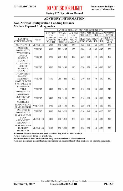
Boeing 737 Operations Manual
Performance Inflight -Advisory Information
737-200ADV/JT8D-9
Copyright © The Boeing Company. See title page for details.
ADVISORY INFORMATIONAdvisory Information
Non-Normal Configuration Landing DistanceMedium Reported Braking Action
LANDING DISTANCE AND ADJUSTMENT (FT)REF DIST
FOR 100000 LB LANDING WEIGHT
WT ADJ PER
5000 LB ABV/BLW 100000 LB
ALT ADJ PER
1000 FTABOVE
SEA LEVEL
WIND ADJ PER 10 KTS
SLOPE ADJ PER 1%
APPROACH SPEED
LANDING CONFIGURATION VREF HEAD
WINDTAIL
WINDDOWN HILL
UP HILL
PER 10 KTS ABOVE VREF
ALL FLAPS UP VREF40+55 6200 280 / -240 530 -260 940 160 -150 360ANTI-SKID
INOPERATIVE VREF40 4880 225 / -195 135 -280 1135 265 -145 330
HYDRAULICS- LOSS OF
SYSTEM A (FLAPS 15)
VREF15 4950 230 / -210 260 -230 870 150 -140 400
HYDRAULICS- LOSS OF
SYSTEM B (FLAPS 15)
VREF15 4510 210 / -190 190 -220 820 130 -110 340
HYDRAULICS- MANUAL
REVERSION(LOSS OF BOTH SYSTEM A & B)
VREF15 5150 250 / -220 290 -240 890 170 -150 450
STABILIZER TRIM
INOPERATIVEVREF15 4400 200 / -180 220 -210 800 120 -110 310
JAMMED ORRESTRICTED
FLIGHTCONTROLS
VREF15 4400 200 / -180 220 -210 800 120 -110 310
LEADING EDGE FLAPS TRANSIT VREF15+5 4730 230 / -190 260 -220 840 140 -120 350
ONE ENGINE INOPERATIVE VREF15 5000 240 / -210 270 -250 940 190 -160 390
TRAILING EDGE FLAP
ASYMMETRY(1≤ FLAPS <15)
VREF40+30 5450 240 / -210 380 -230 870 140 -120 320
TRAILING EDGE FLAPS UP
(FLAPS < 1)VREF40+40 5100 230 / -200 320 -230 850 130 -120 320
Reference distance assumes sea level, standard day, with no wind or slope.Actual (unfactored) distances are shown.Includes distance from 50 ft above runway threshold (1000 ft of air distance).Assumes maximum manual braking and maximum reverse thrust when available on operating engine(s).
D6-27370-200A-TBC PI.32.9October 9, 2007

Boeing 737 Operations Manual
Performance Inflight -Advisory Information
737-200ADV/JT8D-9
Copyright © The Boeing Company. See title page for details.
ADVISORY INFORMATIONAdvisory Information
Non-Normal Configuration Landing DistancePoor Reported Braking Action
LANDING DISTANCE AND ADJUSTMENT (FT)REF DIST
FOR 100000 LB LANDING WEIGHT
WT ADJ PER
5000 LB ABV/BLW 100000 LB
ALT ADJ PER
1000 FTABOVE
SEA LEVEL
WIND ADJ PER 10 KTS
SLOPE ADJ PER 1%
APPROACH SPEED
LANDING CONFIGURATION VREF HEAD
WINDTAIL
WINDDOWN HILL
UP HILL
PER 10 KTS ABOVE VREF
ALL FLAPS UP VREF40+55 7400 360 / -330 650 -340 1330 270 -230 410ANTI-SKID
INOPERATIVE VREF40 5630 280 / -245 170 -390 1865 1140 -265 350
HYDRAULICS- LOSS OF
SYSTEM A (FLAPS 15)
VREF15 5700 310 / -250 310 -300 1230 250 -210 430
HYDRAULICS- LOSS OF
SYSTEM B (FLAPS 15)
VREF15 5290 280 / -240 220 -290 1180 220 -180 380
HYDRAULICS- MANUAL
REVERSION (LOSS OF BOTH SYSTEM A & B)
VREF15 5950 320 / -280 340 -310 1250 260 -220 470
STABILIZER TRIM
INOPERATIVEVREF15 5150 270 / -230 260 -280 1160 210 -170 350
JAMMED ORRESTRICTED
FLIGHTCONTROLS
VREF15 5150 270 / -230 260 -280 1160 210 -170 350
LEADING EDGE FLAPS TRANSIT VREF15+5 5570 300 / -250 310 -300 1200 230 -190 400
ONE ENGINE INOPERATIVE VREF15 6300 330 / -300 340 -360 1430 380 -300 460
TRAILING EDGE FLAP
ASYMMETRY(1≤ FLAPS <15)
VREF40+30 6450 310 / -280 460 -310 1250 240 -200 370
TRAILING EDGE FLAPS UP
(FLAPS < 1)VREF40+40 6080 300 / -260 390 -300 1220 230 -190 370
Reference distance assumes sea level, standard day, with no wind or slope.Actual (unfactored) distances are shown.Includes distance from 50 ft above runway threshold (1000 ft of air distance).Assumes maximum manual braking and maximum reverse thrust when available on operating engine(s).
PI.32.10 D6-27370-200A-TBC October 9, 2007

Boeing 737 Operations Manual
Performance Inflight -Advisory Information
737-200ADV/JT8D-9
Copyright © The Boeing Company. See title page for details.
ADVISORY INFORMATIONAdvisory Information
Brake Cooling ScheduleReference Brake Energy (Millions of Foot Pounds)
Adjusted Brake Energy per Brake (Millions of Foot Pounds)
Cooling Time (Minutes)
BRAKES ON SPEED (KIAS)60 80 100 120 140
WEIGHT (1000 LB)
OAT (°F)
PRESS ALT PRESS ALT PRESS ALT PRESS ALT PRESS ALT0 2 4 0 2 4 0 2 4 0 2 4 0 2 4
13040 4.8 5.2 5.7 8.5 9.2 9.9 13.0 14.1 15.3 18.3 19.9 21.5 22.2 24.0 25.980 5.2 5.7 6.1 9.2 10.0 10.7 14.1 15.3 16.5 19.8 21.4 23.2 23.9 25.9 27.9
120 5.6 6.1 6.6 9.9 10.7 11.5 15.1 16.4 17.7 21.2 23.0 24.9 25.7 27.8 30.0
12040 4.5 4.9 5.3 7.9 8.6 9.2 12.0 13.0 14.0 15.8 17.2 18.6 20.4 22.2 24.080 4.9 5.3 5.8 8.6 9.3 10.0 12.9 14.0 15.2 17.0 18.6 20.0 22.0 24.0 25.9
120 5.2 5.7 6.2 9.2 10.0 10.8 13.8 15.1 16.3 18.3 19.9 21.5 23.6 25.7 27.8
11040 4.2 4.5 4.9 7.2 7.8 8.5 11.1 12.1 13.0 15.1 16.5 17.8 18.5 20.1 21.780 4.5 4.9 5.3 7.8 8.5 9.2 12.0 13.0 14.1 16.3 17.8 19.2 20.0 21.7 23.4
120 4.8 5.2 5.6 8.4 9.1 9.9 12.8 14.0 15.2 17.5 19.0 20.6 21.4 23.3 25.2
10040 3.9 4.2 4.5 6.6 7.1 7.7 10.0 10.9 11.8 13.5 14.7 15.8 16.8 18.2 19.780 4.2 4.5 4.9 7.1 7.7 8.3 10.8 11.8 12.7 14.6 15.8 17.0 18.1 19.6 21.2
120 4.5 4.9 5.2 7.6 8.3 9.0 11.6 12.6 13.6 15.7 17.0 18.3 19.4 21.1 22.7
9040 3.4 3.7 4.0 6.0 6.5 7.1 9.0 9.7 10.5 11.8 12.8 13.8 14.8 16.1 17.480 3.6 4.0 4.3 6.5 7.0 7.6 9.7 10.5 11.4 12.7 13.8 14.9 16.0 17.4 18.8
120 3.9 4.2 4.6 6.9 7.5 8.2 10.4 11.3 12.2 13.6 14.9 16.1 17.2 18.7 20.2
8040 3.1 3.4 3.7 5.2 5.7 6.2 7.9 8.6 9.2 10.0 10.9 11.8 13.0 14.1 15.380 3.3 3.6 3.9 5.6 6.1 6.6 8.5 9.3 10.0 10.8 11.8 12.7 14.1 15.3 16.5
120 3.6 3.9 4.2 6.0 6.6 7.1 9.2 10.0 10.8 11.6 12.6 13.6 15.1 16.4 17.7To correct for wind, enter table with the brakes on speed minus one half the headwind or plus 1.5 times the tailwind.If ground speed is used for brakes on speed, ignore wind, altitude, and OAT effects.
REFERENCE BRAKE ENERGY PER BRAKE (MILLIONS OF FOOT POUNDS)EVENT 2 4 6 8 10 12 14 16 18 20
RTO MAX MAN 2 4 6 8 10 12 14 16 18 20MAX AUTO 1.8 3.5 5.3 7.1 8.7 10.2 11.7 13.1 14.4 15.7MED AUTO 1.5 3.2 4.8 6.3 7.6 8.8 10.0 10.8 11.7 12.5MIN AUTO 1.4 3.0 4.0 4.9 5.8 6.2 6.6 7.5 7.5 7.6
ADJUSTED BRAKE ENERGY PER BRAKE (MILLIONS OF FOOT POUNDS)6 & BELOW 8 10 12 14 15.9 16 TO 20 20 & ABOVE
INFLIGHT GEAR DOWN
NO SPECIAL PROCEDURE REQUIRED
1.0 2.9 4.9 7.0 8.8 CAUTION FUSE PLUG MELT ZONEGROUND 15 28 38 48 56
Observe maximum quick turnaround limit. Table does not consider the benefit of reverse thrust.Table shows energy per brake added by a single stop with all brakes operating. Energy is assumed to be equally distributed among the operating brakes. Total energy is the sum of residual energy plus energy added. Add 1.0 million foot pounds for each taxi mile. When in caution zone, wheel fuse plugs may melt. Delay takeoff and inspect after 30 minutes. If overheat occurs after takeoff, extend gear soon for at least 9 minutes. When in fuse plug melt zone, clear runway immediately. Unless required, do not set parking brake. Do not approach gear or attempt to taxi for 50 minutes. Alert fire equipment.
D6-27370-200A-TBC PI.32.11October 9, 2007

Boeing 737 Operations Manual
Performance Inflight -Advisory Information
737-200ADV/JT8D-9
Copyright © The Boeing Company. See title page for details.
IntentionallyBlank
PI.32.12 D6-27370-200A-TBC October 9, 2007

Boeing 737 Operations Manual
Performance Inflight - Chapter PIEngine Inoperative Section 33
737-200ADV/JT8D-9
FAST
-Doc
PI/P
D T
empl
ate
9/1/
99
Copyright © The Boeing Company. See title page for details.
PI.33 Performance Inflight --Engine InoperativeENGINE INOPEngine Inoperative
Max Continuous EPRBased on engine bleed for packs on, engine and wing anti-ice off
EPR Adjustments for Engine Bleeds
TAT (°C)
PRESSURE ALTITUDE (FT)0 1000 1500 2000 3000 4000 5660 10000 15000 20000 25000 30000 35000 37000
50 1.64 1.64 1.66 1.66 1.66 1.66 1.66 1.66 1.66 1.66 1.64 1.6445 1.67 1.67 1.71 1.71 1.71 1.71 1.71 1.71 1.71 1.71 1.67 1.6740 1.70 1.70 1.75 1.75 1.75 1.75 1.75 1.75 1.75 1.75 1.70 1.7035 1.73 1.73 1.81 1.81 1.81 1.81 1.81 1.81 1.81 1.81 1.73 1.7330 1.76 1.76 1.86 1.86 1.86 1.86 1.86 1.86 1.86 1.86 1.76 1.7625 1.79 1.79 1.91 1.91 1.91 1.91 1.91 1.91 1.91 1.91 1.79 1.7920 1.82 1.82 1.95 1.95 1.95 1.95 1.95 1.95 1.95 1.95 1.82 1.8215 1.86 1.86 2.00 2.00 2.00 2.00 2.00 2.00 2.00 2.00 1.86 1.8610 1.90 1.90 2.04 2.04 2.04 2.04 2.04 2.04 2.04 2.04 1.90 1.905 1.94 1.94 2.06 2.07 2.07 2.07 2.07 2.07 2.07 2.07 1.94 1.94 1.92 1.920 1.98 1.99 2.06 2.09 2.10 2.10 2.10 2.10 2.10 2.10 1.99 1.99 1.97 1.97-5 1.98 2.04 2.06 2.09 2.13 2.13 2.13 2.13 2.13 2.13 2.04 2.04 2.02 2.02
-10 1.98 2.04 2.06 2.09 2.14 2.16 2.16 2.16 2.16 2.16 2.09 2.09 2.07 2.07-15 1.98 2.04 2.06 2.09 2.14 2.19 2.19 2.19 2.19 2.19 2.12 2.12 2.11 2.11-20 1.98 2.04 2.06 2.09 2.14 2.20 2.21 2.21 2.21 2.21 2.15 2.15 2.14 2.14-25 1.98 2.04 2.06 2.09 2.14 2.20 2.24 2.24 2.24 2.24 2.18 2.18 2.17 2.17-30 1.98 2.04 2.06 2.09 2.14 2.20 2.26 2.26 2.26 2.26 2.21 2.21 2.20 2.20-35 1.98 2.04 2.06 2.09 2.14 2.20 2.28 2.28 2.28 2.28 2.23 2.23 2.22 2.22-40 1.98 2.04 2.06 2.09 2.14 2.20 2.30 2.30 2.30 2.30 2.25 2.25 2.24 2.24
BLEED CONFIGURATION
PRESSURE ALTITUDE (FT)BELOW 1500 & ABOVE 20000 1500 THRU 20000
ENGINE ANTI-ICE ON 0.08 0.08ENGINE AND WING ANTI-ICE ON* 0.12 0.12
ENGINE AND WING ANTI-ICE ON** 0.14 0.15*Dual Bleed Source**Single Bleed Source
D6-27370-200A-TBC PI.33.1April 5, 2002

Boeing 737 Operations Manual
Performance Inflight -Engine Inoperative
737-200ADV/JT8D-9
Copyright © The Boeing Company. See title page for details.
ENGINE INOPMAX CONTINUOUS THRUST
Driftdown Speed/Level Off Altitude100 ft/min residual rate of climb
Driftdown/LRC Cruise Range CapabilityGround to Air Miles Conversion
Driftdown/Cruise Fuel and Time
WEIGHT (1000 LB) OPTIMUM DRIFTDOWN
SPEED (KIAS)
LEVEL OFF ALTITUDE (FT)START DRIFT DOWN
LEVEL OFF
ISA + 10°C & BELOW ISA + 15°C ISA + 20°C
130 122 231 10300 8700 6700120 113 222 13100 11800 10300110 104 213 16000 14900 13600100 95 203 18900 18000 1700090 84 193 20500 19900 2000080 75 182 24300 23200 2180070 66 170 28200 27400 2640060 57 158 32300 31600 30900
AIR DISTANCE (NM) GROUND DISTANCE
(NM)
AIR DISTANCE (NM)HEADWIND COMPONENT (KTS) TAILWIND COMPONENT (KTS)
100 80 60 40 20 20 40 60 80 100302 274 251 231 214 200 187 176 166 157 150602 547 501 462 429 400 375 353 333 315 300893 813 747 691 642 600 563 530 501 475 4521179 1077 991 918 855 800 752 709 671 636 6051463 1339 1234 1145 1068 1000 940 888 840 798 7601747 1601 1477 1372 1280 1200 1129 1066 1010 960 9142034 1865 1722 1599 1493 1400 1318 1245 1179 1121 10672326 2133 1969 1828 1707 1600 1506 1422 1348 1280 12192627 2406 2219 2059 1921 1800 1693 1599 1514 1438 1369
AIR DIST (NM)
FUEL REQUIRED (1000 LB)TIME
(HR:MIN)WEIGHT AT START OF DRIFTDOWN (1000 LB)70 80 90 100 110 120 130
200 2.1 2.3 2.4 2.7 2.9 3.1 3.4 0:41400 4.5 5.1 5.6 5.9 6.7 7.3 7.9 1:20600 6.7 7.5 8.4 9.0 10.1 11.0 11.9 1:58800 8.8 9.9 11.1 12.0 13.3 14.6 15.8 2:34
1000 10.8 12.3 13.7 14.9 16.5 18.1 19.6 3:101200 12.8 14.5 16.3 17.7 19.6 21.5 23.3 3:451400 14.7 16.8 18.8 20.4 22.6 24.8 26.9 4:221600 16.6 18.9 21.2 23.1 25.6 28.0 30.5 4:601800 18.5 21.0 23.6 25.8 28.5 31.2 33.9 5:40
Includes APU fuel burn. Driftdown at optimum driftdown speed and cruise at LRC speed.
PI.33.2 D6-27370-200A-TBC April 5, 2002

Boeing 737 Operations Manual
Performance Inflight -Engine Inoperative
737-200ADV/JT8D-9
Copyright © The Boeing Company. See title page for details.
ENGINE INOPMAX CONTINUOUS THRUST
Long Range Cruise Altitude Capability100 ft/min residual rate of climb
Long Range Cruise Control
WEIGHT (1000 LB)
PRESSURE ALTITUDE (FT)ISA + 10°C & BELOW ISA + 15°C ISA + 20°C
120 5700 2300110 10300 7600 4200100 14000 12200 990090 17800 16400 1470080 20000 20000 1960070 23900 22200 2000060 29000 27800 26400
WEIGHT (1000 LB)
PRESSURE ALTITUDE (1000 FT)10 13 15 17 19 21 23 25 27 29 31
120
EPR 1.97MACH .521KIAS 289
FF/ENG 6538
110
EPR 1.89 2.00MACH .502 .529KIAS 278 277
FF/ENG 5898 5982
100
EPR 1.81 1.91 1.99 2.07MACH .482 .507 .525 .545KIAS 266 265 265 265
FF/ENG 5294 5332 5383 5454
90
EPR 1.73 1.82 1.89 1.96 2.04MACH .461 .484 .501 .519 .539KIAS 255 253 252 252 251
FF/ENG 4727 4728 4746 4780 4844
80
EPR 1.64 1.73 1.79 1.86 1.93 2.01 2.10MACH .440 .461 .476 .493 .511 .531 .553KIAS 243 241 240 239 238 238 238
FF/ENG 4202 4169 4162 4166 4191 4253 4339
70
EPR 1.57 1.63 1.69 1.75 1.81 1.88 1.96 2.05 2.14MACH .418 .437 .451 .466 .483 .500 .519 .540 .564KIAS 231 228 227 225 224 223 223 223 223
FF/ENG 3719 3656 3628 3610 3606 3631 3678 3736 3805
60
EPR 1.49 1.55 1.59 1.64 1.69 1.76 1.83 1.91 1.99 2.09 2.18MACH .395 .412 .425 .438 .453 .471 .491 .511 .532 .555 .579KIAS 218 215 213 211 210 210 210 210 210 210 210
FF/ENG 3271 3184 3137 3101 3078 3094 3129 3167 3203 3252 3319
D6-27370-200A-TBC PI.33.3April 5, 2002

Boeing 737 Operations Manual
Performance Inflight -Engine Inoperative
737-200ADV/JT8D-9
Copyright © The Boeing Company. See title page for details.
ENGINE INOPMAX CONTINUOUS THRUST
Long Range Cruise Diversion Fuel and TimeGround to Air Miles Conversion
Reference Fuel and Time Required at Check Point
Fuel Required Adjustment (1000 LB)
AIR DISTANCE (NM) GROUND DISTANCE
(NM)
AIR DISTANCE (NM)HEADWIND COMPONENT (KTS) TAILWIND COMPONENT (KTS)
100 80 60 40 20 20 40 60 80 100306 277 252 232 215 200 190 181 173 166 159620 561 509 467 431 400 380 362 345 330 316938 846 766 701 647 600 570 542 516 493 4731258 1133 1025 937 864 800 759 722 687 656 6291581 1423 1285 1174 1081 1000 949 901 858 820 7851908 1715 1547 1412 1299 1200 1138 1081 1029 982 9402238 2008 1810 1649 1517 1400 1327 1259 1198 1143 10942572 2305 2074 1888 1735 1600 1516 1438 1368 1304 12482910 2604 2339 2128 1953 1800 1704 1616 1536 1464 1401
AIR DIST (NM)
PRESSURE ALTITUDE (1000 FT)10 14 18 22 26
FUEL (1000 LB)
TIME (HR:MIN)
FUEL (1000 LB)
TIME (HR:MIN)
FUEL (1000 LB)
TIME (HR:MIN)
FUEL (1000 LB)
TIME (HR:MIN)
FUEL (1000 LB)
TIME (HR:MIN)
200 3.3 0:44 3.0 0:42 2.7 0:40 2.6 0:39 2.4 0:37400 6.6 1:26 6.1 1:22 5.7 1:18 5.4 1:14 5.2 1:09600 9.8 2:08 9.1 2:02 8.6 1:56 8.2 1:50 7.9 1:43800 13.0 2:51 12.1 2:43 11.4 2:34 11.0 2:25 10.6 2:16
1000 16.1 3:35 15.0 3:24 14.2 3:13 13.6 3:02 13.2 2:511200 19.2 4:19 17.9 4:06 16.9 3:53 16.2 3:39 15.8 3:251400 22.2 5:04 20.7 4:49 19.5 4:33 18.8 4:17 18.2 4:011600 25.1 5:50 23.5 5:32 22.1 5:14 21.2 4:56 20.6 4:371800 28.0 6:36 26.2 6:16 24.6 5:56 23.7 5:35 23.0 5:13
REFERENCE FUEL REQUIRED (1000 LB)
WEIGHT AT CHECK POINT (1000 LB)60 70 80 90 100 110 120
5 -0.7 -0.4 -0.2 0.0 0.2 1.0 2.310 -1.4 -1.0 -0.5 0.0 0.7 2.1 4.215 -2.1 -1.5 -0.7 0.0 1.2 3.1 5.920 -2.8 -2.0 -1.0 0.0 1.7 4.1 7.325 -3.4 -2.4 -1.2 0.0 2.1 5.0 8.530 -4.1 -2.9 -1.5 0.0 2.6 5.7 9.4
PI.33.4 D6-27370-200A-TBC April 5, 2002

Boeing 737 Operations Manual
Performance Inflight -Engine Inoperative
737-200ADV/JT8D-9
Copyright © The Boeing Company. See title page for details.
ENGINE INOPMAX CONTINUOUS THRUST
HoldingFlaps Up
WEIGHT (1000 LB)
PRESSURE ALTITUDE (FT)1500 5000 10000 15000 20000 25000 30000
130EPR 1.67 1.78 1.96KIAS 243 246 246
FF/ENG 6160 6220 6370
120EPR 1.61 1.71 1.88 2.09KIAS 232 236 236 237
FF/ENG 5620 5670 5760 6010
110EPR 1.55 1.64 1.80 1.99KIAS 220 223 227 227
FF/ENG 5110 5130 5180 5360
100EPR 1.50 1.57 1.71 1.90 2.11KIAS 210 211 216 216 217
FF/ENG 4630 4610 4640 4750 4970
90EPR 1.44 1.51 1.64 1.80 2.00KIAS 210 210 210 210 210
FF/ENG 4250 4200 4170 4220 4350
80EPR 1.40 1.46 1.57 1.71 1.89 2.11KIAS 210 210 210 210 210 210
FF/ENG 3920 3870 3820 3820 3890 4100
70EPR 1.36 1.41 1.51 1.64 1.80 2.00KIAS 210 210 210 210 210 210
FF/ENG 3650 3590 3530 3500 3530 3670
60EPR 1.33 1.38 1.47 1.58 1.73 1.91 2.13KIAS 210 210 210 210 210 210 210
FF/ENG 3420 3360 3290 3240 3240 3330 3450This table includes 5% additional fuel for holding in a racetrack pattern.
D6-27370-200A-TBC PI.33.5April 5, 2002

Boeing 737 Operations Manual
Performance Inflight -Engine Inoperative
737-200ADV/JT8D-9
Copyright © The Boeing Company. See title page for details.
IntentionallyBlank
PI.33.6 D6-27370-200A-TBC April 5, 2002

Boeing 737 Operations Manual
Performance Inflight - Chapter PIGear Down Section 34
737-200ADV/JT8D-9
FAST
-Doc
PI/P
D T
empl
ate
9/1/
99
Copyright © The Boeing Company. See title page for details.
PI.34 Performance Inflight --Gear DownGEAR DOWNGear Down
220 KIAS Cruise Altitude CapabilityMax Cruise Thrust, 100 ft/min residual rate of climb
WEIGHT (1000 LB)
PRESSURE ALTITUDE (FT)ISA + 10°C & BELOW ISA + 15°C ISA + 20°C
130 7900125 9500120 10900 5200115 12300 7800110 13800 10000105 15300 11700100 16700 1320095 17800 14500 950090 18900 15800 1170085 19800 16900 1320080 20600 17800 1440075 21300 18700 1540070 22000 19600 1630065 22600 20300 1710060 23100 21100 17900
D6-27370-200A-TBC PI.34.1April 5, 2002

Boeing 737 Operations Manual
Performance Inflight -Gear Down
737-200ADV/JT8D-9
Copyright © The Boeing Company. See title page for details.
GEAR DOWNGear Down
220 KIAS Cruise ControlWEIGHT (1000 LB)
PRESSURE ALTITUDE (1000 FT)6 8 10 12 13 15 17 19 21 23 25
130
EPR 1.62 1.67 1.74 1.81 1.84 1.92MACH .370 .384 .399 .414 .422 .438KIAS 220 220 220 220 220 220
FF/ENG 4556 4554 4564 4602 4626 4686
120
EPR 1.58 1.63 1.69 1.76 1.79 1.87 1.95MACH .370 .384 .399 .414 .422 .438 .456KIAS 220 220 220 220 220 220 220
FF/ENG 4331 4321 4323 4349 4366 4410 4465
110
EPR 1.55 1.60 1.65 1.71 1.75 1.82 1.89 1.97MACH .370 .384 .399 .414 .422 .438 .456 .474KIAS 220 220 220 220 220 220 220 220
FF/ENG 4131 4115 4107 4123 4135 4167 4208 4268
100
EPR 1.52 1.57 1.62 1.67 1.70 1.77 1.84 1.92 2.00MACH .370 .384 .399 .414 .422 .438 .456 .474 .493KIAS 220 220 220 220 220 220 220 220 220
FF/ENG 3957 3938 3921 3929 3936 3958 3987 4033 4111
90
EPR 1.49 1.54 1.59 1.64 1.67 1.73 1.80 1.88 1.96MACH .370 .384 .399 .414 .422 .438 .456 .474 .493KIAS 220 220 220 220 220 220 220 220 220
FF/ENG 3812 3792 3770 3770 3773 3786 3808 3842 3906
80
EPR 1.47 1.51 1.56 1.61 1.64 1.70 1.77 1.84 1.92 2.00MACH .370 .384 .399 .414 .422 .438 .456 .474 .493 .513KIAS 220 220 220 220 220 220 220 220 220 220
FF/ENG 3692 3670 3646 3639 3639 3646 3661 3687 3740 3826
70
EPR 1.45 1.50 1.54 1.59 1.62 1.67 1.74 1.81 1.88 1.97MACH .370 .384 .399 .414 .422 .438 .456 .474 .493 .513KIAS 220 220 220 220 220 220 220 220 220 220
FF/ENG 3589 3565 3542 3528 3526 3528 3537 3557 3601 3678
60
EPR 1.44 1.48 1.52 1.57 1.60 1.65 1.71 1.78 1.86 1.94 2.03MACH .370 .384 .399 .414 .422 .438 .456 .474 .493 .513 .534KIAS 220 220 220 220 220 220 220 220 220 220 220
FF/ENG 3509 3484 3460 3443 3439 3436 3442 3457 3494 3563 3648
PI.34.2 D6-27370-200A-TBC April 5, 2002

Boeing 737 Operations Manual
Performance Inflight -Gear Down
737-200ADV/JT8D-9
Copyright © The Boeing Company. See title page for details.
GEAR DOWNGear Down
220 KIAS Enroute Fuel and TimeGround to Air Miles Conversion
Reference Fuel and Time Required at Check Point
Fuel Required Adjustment (1000 LB)
Descent at 220 KIAS
AIR DISTANCE (NM) GROUND DISTANCE
(NM)
AIR DISTANCE (NM)HEADWIND COMPONENT (KTS) TAILWIND COMPONENT (KTS)
100 80 60 40 20 20 40 60 80 100323 288 259 236 217 200 189 180 171 162 155652 582 521 474 434 400 378 358 340 324 310982 876 784 711 652 600 567 537 510 485 4641311 1169 1047 949 870 800 756 716 679 647 6181640 1462 1309 1187 1087 1000 945 895 850 809 7731970 1756 1572 1425 1305 1200 1134 1074 1019 970 9272299 2049 1834 1663 1523 1400 1323 1253 1189 1132 10822629 2342 2096 1900 1740 1600 1512 1431 1359 1293 12362958 2636 2358 2138 1958 1800 1701 1611 1529 1455 1390
AIR DIST (NM)
PRESSURE ALTITUDE (1000 FT)10 12 16 20 24
FUEL (1000 LB)
TIME (HR:MIN)
FUEL (1000 LB)
TIME (HR:MIN)
FUEL (1000 LB)
TIME (HR:MIN)
FUEL (1000 LB)
TIME (HR:MIN)
FUEL (1000 LB)
TIME (HR:MIN)
200 5.7 0:50 5.4 0:48 5.0 0:46 4.7 0:44 4.5 0:42400 11.4 1:37 11.0 1:34 10.4 1:29 9.8 1:24 9.5 1:20600 17.1 2:24 16.5 2:20 15.6 2:12 14.8 2:05 14.4 1:58800 22.7 3:11 22.0 3:06 20.7 2:55 19.7 2:45 19.2 2:36
1000 28.2 3:58 27.3 3:51 25.7 3:38 24.5 3:25 23.9 3:131200 33.7 4:45 32.6 4:37 30.7 4:21 29.2 4:06 28.6 3:511400 39.1 5:32 37.8 5:23 35.6 5:04 33.9 4:46 33.2 4:291600 44.4 6:20 43.0 6:09 40.5 5:47 38.6 5:27 37.7 5:071800 49.7 7:07 48.1 6:54 45.4 6:30 43.2 6:07 42.2 5:45
REFERENCE FUEL REQUIRED (1000 LB)
WEIGHT AT CHECK POINT (1000 LB)60 70 80 90 100 110 120
5 -0.3 -0.2 -0.1 0.0 0.2 0.5 0.810 -0.6 -0.5 -0.3 0.0 0.5 1.0 1.815 -1.0 -0.7 -0.4 0.0 0.7 1.6 2.620 -1.2 -0.9 -0.5 0.0 0.9 2.1 3.425 -1.5 -1.1 -0.6 0.0 1.1 2.5 4.130 -1.7 -1.3 -0.7 0.0 1.3 2.9 4.735 -1.9 -1.4 -0.8 0.0 1.4 3.2 5.240 -2.0 -1.5 -0.9 0.0 1.5 3.4 5.745 -2.1 -1.6 -0.9 0.0 1.6 3.6 6.0
PRESSURE ALT (1000 FT) 5 10 15 17 19 21 23 25 27 29 31 33DISTANCE (NM) 18 28 37 40 44 47 51 55 58 62 66 69TIME (MINUTES) 7 9 11 12 13 13 14 15 15 16 17 17
D6-27370-200A-TBC PI.34.3April 5, 2002

Boeing 737 Operations Manual
Performance Inflight -Gear Down
737-200ADV/JT8D-9
Copyright © The Boeing Company. See title page for details.
GEAR DOWNGear Down
HoldingFlaps Up
WEIGHT (1000 LB)
PRESSURE ALTITUDE (FT)1500 5000 10000 15000 20000 25000
130EPR 1.56 1.66 1.81KIAS 243 246 246
FF/ENG 5300 5380 5410
120EPR 1.50 1.60 1.74 1.93KIAS 232 236 236 237
FF/ENG 4830 4910 4920 5060
110EPR 1.45 1.53 1.67 1.84KIAS 220 223 227 227
FF/ENG 4390 4420 4470 4540
100EPR 1.41 1.47 1.60 1.75 1.95KIAS 210 211 216 216 217
FF/ENG 4010 3960 4020 4060 4180
90EPR 1.39 1.44 1.55 1.69 1.87KIAS 210 210 210 210 210
FF/ENG 3840 3780 3720 3710 3780
80EPR 1.37 1.42 1.52 1.65 1.82 2.03KIAS 210 210 210 210 210 210
FF/ENG 3700 3640 3570 3550 3590 3760
70EPR 1.35 1.40 1.50 1.62 1.78 1.98KIAS 210 210 210 210 210 210
FF/ENG 3590 3520 3450 3420 3440 3590
60EPR 1.34 1.39 1.48 1.60 1.75 1.94KIAS 210 210 210 210 210 210
FF/ENG 3490 3430 3350 3310 3320 3440This table includes 5% additional fuel for holding in a racetrack pattern.
PI.34.4 D6-27370-200A-TBC April 5, 2002

Boeing 737 Operations Manual
Performance Inflight - Chapter PIText Section 35
737-200ADV/JT8D-9
FAST
-Doc
PI/P
D T
empl
ate
9/1/
99
Copyright © The Boeing Company. See title page for details.
PI.35 Performance Inflight --TextText
IntroductionThis chapter contains information required to complete a normal flight. Inthe event of conflict between data presented in this chapter and thatcontained in the Approved Flight Manual, the Flight Manual shall alwaystake precedence.
General
Takeoff SpeedsThe speeds presented in the Takeoff Speeds table can be used for allperformance conditions except where adjustments must be made to V1 forclearway, stopway, anti-skid inoperative, improved climb, contaminatedrunway situations or brake energy limitations. These speeds may be usedfor weights less than or equal to the performance limited weight.Normal takeoff speeds, V1, VR and V2, with anti-skid on, are read fromthe table by entering with station pressure altitude and moving horizontallyto the appropriate outside air temperature (OAT) column. Proceed downand read V1, VR and V2 for the anticipated takeoff weight and flap setting.Slope and wind adjustments to V1 are obtained by entering the V1Adjustments chart. Adjusted V1 must not exceed VR.
VMCGRegulations prohibit scheduling takeoff with a V1 less than minimum V1for control on the ground, VMCG. Therefore compare the adjusted V1 tothe VMCG. To find VMCG, enter the VMCG table with the airportpressure altitude and actual OAT. If VR is less than VMCG, set VR equalto VMCG, and determine a new V2 by adding the difference between thenormal VR and VMCG to the normal V2.
Clearway and Stopway V1 AdjustmentsTakeoff speed adjustments are to be applied to V1 speed when usingtakeoff weights based on the use of clearway and stopway. Adjust V1 speed by the amount shown in the appropriate column. Theadjusted V1 speed must not exceed VR.Maximum allowable clearway limits are provided for guidance when moreprecise data is not available.
D6-27370-200A-TBC PI.35.1October 8, 2004

Boeing 737 Operations Manual
Performance Inflight -Text
737-200ADV/JT8D-9
Copyright © The Boeing Company. See title page for details.
Stab Trim To find takeoff stabilizer trim setting, enter the Stab Trim Setting tablewith takeoff flap setting and center of gravity (C.G. % MAC) and readrequired stabilizer trim units.
VREFThe Reference Speed table contains flaps 40, 30 and 15 landing speeds fora given weight. Apply wind adjustments shown as required.
Flap Maneuver SpeedsThis table provides the flap speed schedule for recommended maneuveringspeed. The speed schedule is a function of weight and will provideadequate maneuver margin above stall at all weights.During flap retraction/extension, movement of the flap to the next positionshould be initiated when reaching the maneuver speed for the existing flap.
Slush/Standing Water TakeoffExperience has shown that aircraft performance may deterioratesignificantly on runways covered with snow, slush, standing water or ice.Therefore, reductions in field/obstacle limited takeoff weight and revisedtakeoff speeds are necessary. The tables are intended for guidance inaccordance with advisory material and are based on all engines operatingthroughout the takeoff.The entire runway is assumed to be completely covered by a contaminantof uniform thickness and density. Therefore this information isconservative when operating under typical colder weather conditionswhere patches of slush exist and some degree of sanding is common.Takeoffs in slush/standing water depths greater than 0.50 inches (13 mm)are not recommended because of possible airplane damage as a result ofslush/standing water impingement on the airplane structure. The use ofassumed temperature method for reduced thrust is not allowed oncontaminated runways. Interpolation for slush/standing water depthsbetween the values shown is permitted.Takeoff weight determination:Instructions for Using Tables:1. Determine the dry field/obstacle limit weight for the anticipated flapsetting.2. Enter the Weight Adjustment table with the dry field/obstacle limitweight to obtain the slush/standing water weight adjustment for the slushdepth and airport pressure altitude.
PI.35.2 D6-27370-200A-TBC October 8, 2004

Boeing 737 Operations Manual
Performance Inflight -Text
737-200ADV/JT8D-9
Copyright © The Boeing Company. See title page for details.
3. Determine takeoff speeds VR and V2 for the actual brake release weightfrom the Takeoff Speeds chart.Interpolate for intermediate slush depths as required using the dry runwaycondition as zero slush depth.
Anti-skid InoperativeFor anti-skid inoperative, the runway limited maximum gross weight atbrake release and the V1 speed must be reduced to allow for the effect onaccelerate-stop performance as detailed in the Approved Airplane FlightManual. Obstacle clearance capability must also be considered since thereduced V1 speed will increase the distance required to achieve a givenheight above the runway following engine failure. A simplified methodwhich conservatively accounts for the effects of anti-skid inoperative isshown below. Reduce the dry runway/obstacle limited weight at brakerelease obtained from the takeoff performance charts in this section orfrom the specific airport analysis and the associated V1 (i.e., V1 for therunway/obstacle limited weight at brake release) by the weight and V1values shown in the table below. (Note that the resulting V1 must not beless than VMCG value.)For takeoff below the anti-skid inoperative limited weight it is onlynecessary to ensure that the V1 speed set does not exceed the anti-skidlimited V1 value.
If the resulting V1 is less than minimum V1, takeoff is permitted with V1set equal to VMCG. Detailed analysis for the specific case from the AFM may yield a lessrestrictive penalty.
ANTI-SKID V1 ADJUSTMENTSRUNWAY LENGTH
(FT)
V1 ADJUSTMENTS
FLAPS 1 FLAPS 2 FLAPS 5 FLAPS 10 FLAPS 15 FLAPS 25
5000 -25 -225500* -24 -21 -19 -19*6000 -22 -22 -20 -18 -186500 -21 -21 -20 -18 -187000 -20 -20 -20 -198000 -20 -19 -189000 -18 -17
10000 -16*Minimum anti-skid inop runway length at flaps 25Decrease weight by 10000 lb for all flaps shown above.
D6-27370-200A-TBC PI.35.3October 8, 2004

Boeing 737 Operations Manual
Performance Inflight -Text
737-200ADV/JT8D-9
Copyright © The Boeing Company. See title page for details.
Takeoff EPRTo find Takeoff EPR based on normal engine bleed for air conditioningpacks on, enter Takeoff EPR table with airport pressure altitude and airportOAT and read EPR. For packs off operation, apply the EPR adjustmentshown below the table. No takeoff EPR adjustment is required for winganti-ice operation.
Reduced Takeoff EPRThe tables present the allowable Takeoff EPR Reduction as a function ofActual OAT and Surplus Weight which is defined as the differencebetween the Performance Limited TOGW and the Actual TOGW. Thesetables are valid for engine A/C bleed on or off, any flap setting. They arenot valid when the maximum takeoff weight is limited by obstacles, brakeenergy or tire speed. Since the tables are conservative, larger reductions inEPR may be achieved under some conditions by using the AssumedTemperature Method described in the AFM Appendix.Enter the Field Length Limited section of the table appropriate for theairplane pressure altitude with the Surplus Weight based on the field lengthlimit (i.e., Field length limited weight minus actual weight). Read theallowable Takeoff EPR Reduction. Then enter the Climb Limited sectionof the table with the Surplus Weight based on the climb limit anddetermine the allowable Takeoff EPR Reduction. Use the smaller of thetwo reductions. Enter the Minimum EPR table with the pressure altitude.The Takeoff EPR, after the reduction is applied, should not be less thanthis minimum. Apply the noted V1, VR and V2 adjustments.Takeoff with assumed temperature reduced thrust is not permitted when:runway is contaminated with water, ice, slush or snow; anti-skid isinoperative. Use of this procedure is not recommended if potentialwindshear conditions exist.
Max Climb EPRThis table shows Max Climb EPR based on normal engine bleed for packson and anti-ice off. Enter the table with pressure altitude and TAT andread EPR. EPR adjustments are shown for anti-ice operation.
Go-around EPRTo find Go-around EPR based on normal engine bleed for packs on andwing anti-ice off, enter the Go-around EPR table with airport pressurealtitude and reported OAT or TAT and read EPR. For packs off, apply theEPR adjustment shown below the table. EPR adjustments are also shownfor engine and wing anti-ice operations.
PI.35.4 D6-27370-200A-TBC October 8, 2004

Boeing 737 Operations Manual
Performance Inflight -Text
737-200ADV/JT8D-9
Copyright © The Boeing Company. See title page for details.
Flight with Unreliable Airspeed / Turbulent Air PenetrationPitch attitude and average EPR information is provided for use in allphases of flight in the event of unreliable airspeed/Mach indicationsresulting from blocking or freezing of the pitot system. Loss of radome orturbulent air may also cause unreliable airspeed/Mach indications. Thecruise table in this section may also be used for turbulent air penetration.Pitch attitude is shown in bold type for emphasis since altitude and/orvertical speed indications may also be unreliable.
All Engines
Long Range Cruise Maximum Operating AltitudeMaximum altitudes are shown for a given cruise weight and maneuvercapability. This table considers both thrust and buffet limits, providing themore limiting of the two. Any data that is thrust limited is denoted by anasterisk and represents only a thrust limited condition in level flight with100 ft/min residual rate of climb. Flying above these altitudes withsustained banks in excess of approximately 15° may cause the airplane tolose speed and/or altitude.Note that the altitudes shown in the table are limited to the maximumcertified altitude of 37000 ft.
Long Range Cruise ControlThese tables provide target EPR, Long Range Cruise Mach number, KIASand standard day fuel flow per engine for the airplane weight and pressurealtitude. As indicated by the shaded area, at optimum altitude .72Mapproximates the Long Range Cruise Mach schedule.
Long Range Cruise Enroute Fuel and TimeLong Range Cruise Enroute Fuel and Time tables are provided todetermine remaining time and fuel required to destination. The data isbased on Long Range Cruise and .70/280/250 descent. Tables arepresented for low altitudes and high altitudes.To determine remaining fuel and time required, first enter the Ground toAir Miles Conversion table to convert ground distance and enroute wind toan equivalent still air distance for use with the Reference Fuel and Timetables. Next, enter the Reference Fuel and Time table with air distancefrom the Ground to Air Miles Conversion table and the desired altitude andread Reference Fuel and Time Required. Lastly, enter the Fuel RequiredAdjustment table with the Reference Fuel and the actual weight atcheckpoint to obtain fuel required to destination.
D6-27370-200A-TBC PI.35.5October 8, 2004

Boeing 737 Operations Manual
Performance Inflight -Text
737-200ADV/JT8D-9
Copyright © The Boeing Company. See title page for details.
Long Range Cruise Wind-Altitude TradeWind is a factor which may justify operations considerably below optimumaltitude. For example, a favorable wind component may have an effect onground speed which more than compensates for the loss in air range.Using this table, it is possible to determine the break-even wind (advantagenecessary or disadvantage that can be tolerated) to maintain the same rangeat another altitude and long range cruise speed. The tables make noallowance for climb or descent time, fuel or distance, and are based oncomparing ground fuel mileage.
DescentDistance and time for descent are shown for a .70/280/250 descent speedschedule. Enter the table with top of descent pressure altitude and readdistance in nautical miles and time in minutes. Data is based on flight idlethrust descent in zero wind. Allowances are included for a straight-inapproach with gear down and landing flaps at the outer marker.
HoldingTarget EPR, indicated airspeed and fuel flow per engine information istabulated for holding with flaps up based on the optimum holding speedschedule. This is the higher of the maximum endurance speed and themaneuvering speed. Small variations in airspeed will not appreciablyaffect the overall endurance time. Enter the table with weight and pressurealtitude to read EPR, KIAS and fuel flow per engine.
Advisory Information
Autobrake Landing DistanceThe Autobrake Landing Distance tables are provided as advisoryinformation to assist in the selection of the most desirable autobrakesetting for a given field length. It is not to be used to determine requiredfield length. This data reflects actual landing distances on a dry runway forsetting MINIMUM through MAXIMUM, from touchdown to full stop,with or without reverse thrust. The tables include typical flare distancesfrom threshold.To use the Autobrake Landing Distance table, determine the appropriatetable to use. The Digital Autobrake Landing Distance table is onlyapplicable if Autobrake Control Valve Module, Boeing part number60800263 is installed. Enter the chart with the estimated approach speedand determine the actual stopping distance from touchdown for a givenautobrake setting. If airspeed is used for approach speed, adjust landingdistance for pressure altitude and tailwind effects.
PI.35.6 D6-27370-200A-TBC October 8, 2004

Boeing 737 Operations Manual
Performance Inflight -Text
737-200ADV/JT8D-9
Copyright © The Boeing Company. See title page for details.
Selection of an autobrake setting results in a constant rate of deceleration.Maximum effort manual braking should achieve shorter landing distancethan the MAXIMUM setting.
Slippery Runway Landing DistanceLanding distances are the actual landing distances and do not include the1.67% regulatory factor. Therefore they cannot be used to determinedispatch required landing field length. When landing on slippery runwaysor runways contaminated with ice, snow, slush or standing water, thereported braking action must be considered. If the surface is affected bywater, snow or ice, and the braking action is reported as “good,” conditionsshould not be expected to be as good as on clean dry runways. The value“good” is comparative and is intended to mean that airplanes should notexperience braking or directional control difficulties when landing. Theperformance level used to calculate the “good” data is consistent with wetrunway testing done on early Boeing jets. The performance level used tocalculate the “poor” data reflects runways covered with wet ice. Readlanding distance for the reported braking action at the airplane weight, andthen apply the adjustments for airport pressure altitude and approach speedas required.
Non-normal Configuration Landing DistanceAdvisory information is provided to support non-normal configurationsthat affect landing performance of the airplane. Landing distances areshown for dry runway and good, medium and poor reported braking action.Each non-normal configuration is listed with its recommended approachspeed. Landing distance can be determined for the reference landingweight and then adjusted for actual weight and pressure altitude.
Brake Cooling ScheduleAdvisory information is provided to assist in avoiding the problemsassociated with hot brakes. For normal operation, most landings are atweights below the AFM quick turnaround limit weight.Use of the recommended cooling schedule will help avoid brake overheatand fuse plug problems that could result from repeated landings at shorttime intervals or a rejected takeoff.Enter the Brake Cooling Schedule table with the airplane weight andbrakes on speed, adjusted for wind at the appropriate temperature andaltitude condition. Instructions for applying wind adjustments are includedbelow the table. Linear interpolation may be used to obtain intermediate
D6-27370-200A-TBC PI.35.7April 7, 2006

Boeing 737 Operations Manual
Performance Inflight -Text
737-200ADV/JT8D-9
Copyright © The Boeing Company. See title page for details.
values. The resulting number is the reference brake energy per brake inmillions of foot-pounds, and represents the amount of energy absorbed byeach brake during a rejected takeoff.To determine the energy per brake absorbed during landing, enter theAdjusted Brake Energy Per Brake table with the reference brake energy perbrake and the type of braking used during landing (RTO Max Man, MaxAuto, Med Auto or Min Auto). The resulting number is the adjusted brakeenergy per brake and represents the energy absorbed in each brake duringthe landing.The recommended cooling time is found in the final table by entering withthe adjusted brake energy per brake. Times are provided for groundcooling and inflight gear down cooling.
Engine Inoperative
Max Continuous EPRPower setting is based on one engine operating with one A/C packoperating and all anti-ice bleeds off. Enter the table with pressure altitudeand TAT to read EPR.It is desirable to maintain engine thrust within the limits of the Max Cruisethrust rating. However, where thrust in excess of Max Cruise rating isrequired, such as for meeting terrain clearance, ATC altitude assignments,or to attain maximum range capability, it is permissible to use the thrustneeded up to the Max Continuous thrust rating. The Max Continuousthrust rating is intended primarily for emergency use at the discretion ofthe pilot and is the maximum thrust that may be used continuously.
Driftdown Speed/Level Off AltitudeThe table shows optimum driftdown speed as a function of cruise weightat start of driftdown. Also shown are the approximate weight and pressurealtitude at which the airplane will level off considering 100 ft/min residualrate of climb.The level off altitude is dependent on air temperature (ISA deviation).
Driftdown/LRC Range CapabilityThis table shows the range capability from the start of driftdown.Driftdown is continued to level off altitude. As weight decreases due tofuel burn, the airplane is accelerated to Long Range Cruise speed. Cruiseis continued at level off altitude and Long Range Cruise speed.
PI.35.8 D6-27370-200A-TBC April 7, 2006

Boeing 737 Operations Manual
Performance Inflight -Text
737-200ADV/JT8D-9
Copyright © The Boeing Company. See title page for details.
To determine fuel required, enter the Ground to Air Miles Conversion tablewith the desired ground distance and adjust for anticipated winds to obtainair distance to destination. Then enter the Driftdown/Cruise Fuel and Timetable with air distance and weight at start of driftdown to determine fueland time required. If altitudes other than the level off altitude are used,fuel and time required may be obtained by using the Engine InoperativeLong Range Cruise Diversion Fuel and Time table.
Long Range Cruise Altitude CapabilityThe table shows the maximum altitude that can be maintained at a givenweight and air temperature (ISA deviation), based on Long Range Cruisespeed, Max Continuous thrust, and 100 ft/min residual rate of climb.
Long Range Cruise ControlThe table provides target EPR, engine inoperative Long Range CruiseMach number, KIAS and fuel flow for the airplane weight and pressurealtitude. The fuel flow values in this table reflect single engine fuel burn.To conservatively account for APU fuel burn, add 115 kg/hr to fuel flowvalues.
Long Range Cruise Diversion Fuel and TimeTables are provided for crews to determine the fuel and time required toproceed to an alternate airfield with one engine inoperative. The data isbased on single engine Long Range Cruise speed and .70/280/250 descent.Enter with Air Distance as determined from the Ground to Air MilesConversion table and read Fuel and Time required at the cruise pressurealtitude. Adjust the fuel obtained for deviation from the reference weightat checkpoint as required by entering the Fuel Required Adjustment tablewith the fuel required for the reference weight and the actual weight atcheckpoint.
HoldingSingle engine holding data is provided in the same format as the all engineholding data and is based on the same assumptions.
Gear DownThis section contains performance for airplane operation with the landinggear extended for all phases of flight. The data is based on engine bleedsfor normal air conditioning.Note: The Flight Management Computer System (FMCS) does not containspecial provisions for operation with landing gear extended. As a result,the FMCS will generate inappropriate enroute speed schedules, display
D6-27370-200A-TBC PI.35.9April 3, 2007

Boeing 737 Operations Manual
Performance Inflight -Text
737-200ADV/JT8D-9
Copyright © The Boeing Company. See title page for details.
non-conservative predictions of fuel burn, estimated time of arrival (ETA),maximum altitude, and compute overly shallow descent path. An accurateestimated time of arrival (ETA) is available if current speed or Mach isentered into the VNAV cruise page.Tables for gear down performance in this section are identical in formatand used in the same manner as tables for the gear up configurationpreviously described.
PI.35.10 D6-27370-200A-TBC April 7, 2006

Boeing 737 Operations Manual
Index Chapter IndexNon-Normal Checklists Section 1
Copyright © The Boeing Company. See title page for details.
Index.1 Index-Non-Normal ChecklistsAABORTED ENGINE START . . . . . . . . . . . . . . . . . . . . . . . . . . . . . 0.1,7.1AIRSPEED UNRELIABLE . . . . . . . . . . . . . . . . . . . . . . . . . . . . . . 0.2,10.1ALL FLAPS UP LANDING . . . . . . . . . . . . . . . . . . . . . . . . . . . . . . . . . . 9.1ALTITUDE ALERT . . . . . . . . . . . . . . . . . . . . . . . . . . . . . . . . . . . . . . . 15.1ANTISKID INOPERATIVE . . . . . . . . . . . . . . . . . . . . . . . . . . . . . . . . . 14.1APU DET INOP . . . . . . . . . . . . . . . . . . . . . . . . . . . . . . . . . . . . . . . 7.1,8.1APU FIRE . . . . . . . . . . . . . . . . . . . . . . . . . . . . . . . . . . . . . . . . . . . 7.2,8.1APU HIGH OIL TEMPERATURE OR LOW OIL PRESSURE . . . . . . . 7.2APU OVERSPEED . . . . . . . . . . . . . . . . . . . . . . . . . . . . . . . . . . . . . . . 7.3AUTO BRAKE DISARM . . . . . . . . . . . . . . . . . . . . . . . . . . . . . . . . . . 14.1AUTO FAIL/UNSCHEDULED PRESSURIZATION CHANGE . . . . 0.3,2.1AUTOMATIC UNLOCK . . . . . . . . . . . . . . . . . . . . . . . . . . . . . . . . . . . . 1.1AUTOPILOT DISENGAGE . . . . . . . . . . . . . . . . . . . . . . . . . . . . . . . . . 4.1
BBLEED TRIP OFF . . . . . . . . . . . . . . . . . . . . . . . . . . . . . . . . . . . . . . . . 2.2BRAKE PRESSURE INDICATOR ZERO PSI . . . . . . . . . . . . . . . . . . 14.2BUS OFF . . . . . . . . . . . . . . . . . . . . . . . . . . . . . . . . . . . . . . . . . . . . . . . 6.1
CCABIN ALTITUDE WARNING OR RAPID
DEPRESSURIZATION . . . . . . . . . . . . . . . . . . . . . . . . . . . . . . . . 0.4,2.3CARGO FIRE . . . . . . . . . . . . . . . . . . . . . . . . . . . . . . . . . . . . . . . . . . . 8.2CARGO FIRE DETECTOR FAULT . . . . . . . . . . . . . . . . . . . . . . . . . . . 8.2CROSSFEED SELECTOR INOPERATIVE . . . . . . . . . . . . . . . . . . . . 12.1CSD HIGH OIL TEMPERATURE . . . . . . . . . . . . . . . . . . . . . . . . . . . . 6.1CSD LOW OIL PRESSURE . . . . . . . . . . . . . . . . . . . . . . . . . . . . . . . . 6.2
DDITCHING . . . . . . . . . . . . . . . . . . . . . . . . . . . . . . . . . . . . . . . . . . . . . . 0.5DOOR ANNUNCIATOR . . . . . . . . . . . . . . . . . . . . . . . . . . . . . . . . . . . . 1.2DUAL BLEED . . . . . . . . . . . . . . . . . . . . . . . . . . . . . . . . . . . . . . . . . . . 2.4DUCT OVERHEAT . . . . . . . . . . . . . . . . . . . . . . . . . . . . . . . . . . . . . . . 2.4
D6-27370-200A-TBC Index.1.1April 9, 2008

Boeing 737 Operations Manual
Index -Non-Normal Checklists
Copyright © The Boeing Company. See title page for details.
EEMERGENCY DESCENT . . . . . . . . . . . . . . . . . . . . . . . . . . . . . . . 0.8,2.5EMERGENCY EXIT LIGHTS NOT ARMED . . . . . . . . . . . . . . . . . . . . 1.5ENGINE COWL VALVE OPEN . . . . . . . . . . . . . . . . . . . . . . . . . . . . . . 3.1ENGINE FAILURE/SHUTDOWN . . . . . . . . . . . . . . . . . . . . . . . . . . . . . 7.4ENGINE FIRE, SEVERE DAMAGE OR SEPARATION . . . . . . . . . 7.6,8.4ENGINE FUEL LEAK . . . . . . . . . . . . . . . . . . . . . . . . . . . . . . . . . 0.10,12.2ENGINE HIGH OIL TEMPERATURE . . . . . . . . . . . . . . . . . . . . . . . . . 7.8ENGINE IN-FLIGHT START . . . . . . . . . . . . . . . . . . . . . . . . . . . 0.12,7.10ENGINE LIMIT/SURGE/STALL . . . . . . . . . . . . . . . . . . . . . . . . . . . . . 7.12ENGINE LOW OIL PRESSURE . . . . . . . . . . . . . . . . . . . . . . . . . . . . 7.14ENGINE OIL FILTER BYPASS . . . . . . . . . . . . . . . . . . . . . . . . . . . . . 7.16ENGINE OVERHEAT . . . . . . . . . . . . . . . . . . . . . . . . . . . . . . . . . 7.17,8.6ENGINE TAILPIPE FIRE . . . . . . . . . . . . . . . . . . . . . . . . . . . . . . . 7.18,8.7EQUIPMENT COOLING OFF . . . . . . . . . . . . . . . . . . . . . . . . . . . . . . . 2.6EVACUATION . . . . . . . . . . . . . . . . . . . . . . . . . . . . . . . . . . Back Cover.2
FFEEL DIFFERENTIAL PRESSURE . . . . . . . . . . . . . . . . . . . . . . . . . . 9.2FILTER ICING . . . . . . . . . . . . . . . . . . . . . . . . . . . . . . . . . . . . . . . . . . 12.4FLIGHT CONTROL LOW PRESSURE . . . . . . . . . . . . . . . . . . . . . . . . 9.2FLIGHT RECORDER OFF . . . . . . . . . . . . . . . . . . . . . . . . . . . . . . . . 10.1FUEL HEAT VALVE FAILURE . . . . . . . . . . . . . . . . . . . . . . . . . . . . . . 12.5FUEL PUMP LOW PRESSURE . . . . . . . . . . . . . . . . . . . . . . . . . . . . 12.6FUEL TEMP LOW . . . . . . . . . . . . . . . . . . . . . . . . . . . . . . . . . . . . . . . 12.8FUSELAGE FIRES CLASS B PASS/CARGO OR ALL CARGO . . . . . 8.8FUSELAGE FIRES CLASS E ALL CARGO . . . . . . . . . . . . . . . . . . . 8.10
GGEAR LEVER WILL NOT MOVE UP AFTER TAKEOFF . . . . . . . . . 14.3GROUND PROXIMITY INOP . . . . . . . . . . . . . . . . . . . . . . . . . . . . . . 15.1
HHIGH ENGINE VIBRATION . . . . . . . . . . . . . . . . . . . . . . . . . . . . . . . . 7.19HYDRAULIC PUMP LOW PRESSURE . . . . . . . . . . . . . . . . . . . . . . . 13.1HYDRAULIC PUMP OVERHEAT . . . . . . . . . . . . . . . . . . . . . . . . . . . 13.1
Index.1.2 D6-27370-200A-TBC April 9, 2008

Boeing 737 Operations Manual
Index -Non-Normal Checklists
Copyright © The Boeing Company. See title page for details.
IINADVERTENT TRANSFER OF FUEL INTO AUX TANK . . . . . . . . 12.8INADVERTENT TRANSFER OF FUEL INTO CENTER TANK . . . . . 12.9
JJAMMED OR RESTRICTED FLIGHT CONTROLS . . . . . . . . . . 0.14,9.3
LLANDING GEAR LEVER JAMMED IN THE UP POSITION . . . . . . . 14.6LEADING EDGE FLAPS TRANSIT . . . . . . . . . . . . . . . . . . . . . . . . . . . 9.6LOCK FAIL . . . . . . . . . . . . . . . . . . . . . . . . . . . . . . . . . . . . . . . . . . . . . 1.5LOSS OF BOTH ENGINE DRIVEN GENERATORS . . . . . . . . . . . . . 6.4LOSS OF SYSTEM A . . . . . . . . . . . . . . . . . . . . . . . . . . . . . . . . . . . . 13.2LOSS OF SYSTEM B . . . . . . . . . . . . . . . . . . . . . . . . . . . . . . . . . . . . 13.6
MMACH TRIM FAIL . . . . . . . . . . . . . . . . . . . . . . . . . . . . . . . . . . . . . . . . 9.9MANUAL GEAR EXTENSION . . . . . . . . . . . . . . . . . . . . . . . . . . . . 14.12MANUAL REVERSION . . . . . . . . . . . . . . . . . . . . . . . . . . . . . . . . . . . 13.8MINIMUM FUEL OPERATION . . . . . . . . . . . . . . . . . . . . . . . . . . . . 12.10
NNO STARTER CUTOUT/START VALVE OPEN . . . . . . . . . . . . . . . . 7.22
OOFF SCHEDULE DESCENT . . . . . . . . . . . . . . . . . . . . . . . . . . . . . . . 2.6ONE ENGINE INOPERATIVE LANDING . . . . . . . . . . . . . . . . . . . . . 7.24OVERSPEED . . . . . . . . . . . . . . . . . . . . . . . . . . . . . . . . . . . . . . . . . . 15.1
PPACK TRIP OFF . . . . . . . . . . . . . . . . . . . . . . . . . . . . . . . . . . . . . . . . . 2.8PARTIAL OR GEAR UP LANDING . . . . . . . . . . . . . . . . . . . . . . . . . 14.20PASSENGER OXYGEN ON . . . . . . . . . . . . . . . . . . . . . . . . . . . . . . . . 1.5PITOT STATIC HEAT MALFUNCTIONS . . . . . . . . . . . . . . . . . . . . . . . 3.1
RRADIO TRANSMIT CONTINUOUS (STUCK MICROPHONE
SWITCH) . . . . . . . . . . . . . . . . . . . . . . . . . . . . . . . . . . . . . . . . . 0.16,5.1REVERSER UNLOCKED (IN FLIGHT) . . . . . . . . . . . . . . . . . . . . . . . 7.26RUNAWAY STABILIZER . . . . . . . . . . . . . . . . . . . . . . . . . . . . . . . . . . 9.10
D6-27370-200A-TBC Index.1.3April 9, 2008

Boeing 737 Operations Manual
Index -Non-Normal Checklists
Copyright © The Boeing Company. See title page for details.
SSMOKE OR FUMES REMOVAL . . . . . . . . . . . . . . . . . . . . . . . . 0.20,8.14SMOKE, FIRE OR FUMES . . . . . . . . . . . . . . . . . . . . . . . . . . . . 0.18,8.12SPEED BRAKE DO NOT ARM . . . . . . . . . . . . . . . . . . . . . . . . . . . . . 9.10STABILIZER OUT OF TRIM . . . . . . . . . . . . . . . . . . . . . . . . . . . . . . . 9.11STABILIZER TRIM INOPERATIVE . . . . . . . . . . . . . . . . . . . . . . 0.22,9.12STANDBY HYDRAULIC LOW PRESSURE . . . . . . . . . . . . . . . . . . 13.11STANDBY HYDRAULIC LOW QUANTITY . . . . . . . . . . . . . . . . . . . 13.11STANDBY POWER OFF . . . . . . . . . . . . . . . . . . . . . . . . . . . . . . . . . . . 6.7STANDBY RUDDER ON . . . . . . . . . . . . . . . . . . . . . . . . . . . . . . . . . . 9.14
TTAILSTRIKE ON TAKEOFF . . . . . . . . . . . . . . . . . . . . . . . . . . . . . 0.24,1.6TAKEOFF CONFIGURATION . . . . . . . . . . . . . . . . . . . . . . . . . . . . . . 15.1THRUST REVERSER ISOLATION VALVE . . . . . . . . . . . . . . . . . . . . 7.28TRAILING EDGE FLAP ASYMMETRY . . . . . . . . . . . . . . . . . . . . . . . 9.16TRAILING EDGE FLAP DISAGREE . . . . . . . . . . . . . . . . . . . . . . . . . 9.18TRAILING EDGE FLAPS UP LANDING . . . . . . . . . . . . . . . . . . . . . . 9.22TRANSFER BUS OFF . . . . . . . . . . . . . . . . . . . . . . . . . . . . . . . . . . . . . 6.7
UUNCOMMANDED RUDDER/YAW OR ROLL . . . . . . . . . . . . . . 0.26,9.24
VVOLCANIC ASH . . . . . . . . . . . . . . . . . . . . . . . . . . . . . . . . . . . . 0.30,7.30
WWARNING HORN - CABIN ALTITUDE OR CONFIGURATION 0.32,15.2WHEEL WELL FIRE . . . . . . . . . . . . . . . . . . . . . . . . . . . . . . . . 8.16,14.22WINDOW DAMAGE . . . . . . . . . . . . . . . . . . . . . . . . . . . . . . . . . . 0.34,1.8WINDOW OPEN . . . . . . . . . . . . . . . . . . . . . . . . . . . . . . . . . . . . 0.38,1.12WINDOW OVERHEAT . . . . . . . . . . . . . . . . . . . . . . . . . . . . . . . . . . . . 3.2WING ANTI-ICE VALVE OPEN . . . . . . . . . . . . . . . . . . . . . . . . . . . . . . 3.2WING-BODY OVERHEAT . . . . . . . . . . . . . . . . . . . . . . . . . . . . . . . . . 2.10
YYAW DAMPER . . . . . . . . . . . . . . . . . . . . . . . . . . . . . . . . . . . . . . . . . . 9.29
Index.1.4 D6-27370-200A-TBC April 9, 2008

Boeing 737 Operations Manual Back Cover.1
Copyright © The Boeing Company. See title page for details.
NNC.Back Cover Non-Normal Checklists-Unannunciated Checklists
Evacuation checklist is on the reverse side of this page.
D6-27370-200A-TBC Back Cover.1April 9, 2008

Boeing 737 Operations Manual Back Cover.2
Copyright © The Boeing Company. See title page for details.
Condition: Evacuation is needed.Parking brake . . . . . . . . . . . . . . . . . . . . . . . . . . . . . . . . . . . . .SetSpeedbrake lever . . . . . . . . . . . . . . . . . . . . . . . . . . . . . . .DOWNFLAP lever . . . . . . . . . . . . . . . . . . . . . . . . . . . . . . . . . . . . . . . 40STANDBY POWER . . . . . . . . . . . . . . . . . . . . . . . . . . . . . . . . BATPressurization mode selector . . . . . . . . . . . . . . . . . . . MAN DCOutflow valve switch . . . . . . . . . . . . . . . . . . . . . . . . . . . . OPEN
Hold until the outflow valve is fully open.If time allows, verify flaps are 40 before the engine start levers are moved to CUTOFF.Engine start levers (Both) . . . . . . . . . . . . . . . . . . . . . . CUTOFFAdvise the cabin to evacuate.Advise the tower.Engine and APU fire switches (All) . . . . . . .Override and pull
If an engine or APU fire warning occurs:Related fire switch. . . . . . . . . . . . . . . . . . . . Rotate and hold
Rotate to the stop and hold for 1 second.
EVACUATION
D6-27370-200A-TBCBack Cover.2 April 9, 2008