Embed Size (px)
Citation preview
QUESTIONS AND ANSWERS
PART-A
UNIT-I
1. Explain the need and necessity of proper sanitation for a town. ( Dec 13/Jan 14,
June/July 2015)
Answer: Need & Necessity for sanitation
Every community produces both liquid and solid wastes .The liquid portion –waste water–
is essentially the water supply of the community after it has been fouled by a variety of uses such
as spent water from bathroom kitchen, lavatory basins, house and street washings, from various
industrial processes semi solid wastes of human and animal excreta, dry refuse of house and
street sweepings, broken furniture, wastes from industries etc are produced daily.
If proper arrangements for the collection, treatment and disposal are not made, they will go on
accumulating and create foul condition. If untreated water is accumulating, the decomposition of
the organic materials it contains can lead to the production of large quantity of mal odorous
gases. It also contains nutrients, which can stimulate the growth of aquatic plants and it may
contain toxic compounds. Therefore in the interest of community of the city or town, it is most
essential to collect, treat and dispose of all the waste products of the city in such a way that it
may not cause any hazardous effects on people residing in town and environment.
Waste water engineering is defined as the branch of the environmental engineering where
the basic principles of the science and engineering for the problems of the water pollution
problems. The ultimate goal of the waste water management is the protection of the
environmental in manner commensurate with the economic, social and political concerns.
Although the collection of stream water and drainage dates from ancient times the collection
of waste water can be treated only to the early 1800s. The systematic treatment of waste water
followed in the 1800s and 1900s.
Importance of sewerage system
One of the fundamental principles of sanitation of the community is to remove all
decomposable matter, solid waste, liquid or gaseous away from the premises of dwellings as fast
as possible after it is produced, to a safe place , without causing any nuisance and dispose it in a
suitable manner so as to make it permanently harmless.
Sanitation though motivated primarily for meeting the ends of preventive health has come to be
recognized as a way of life. In this context, development of the sanitation infrastructure of any
country could possibly serve as a sensitive index of its level of prosperity. It is needless to
emphasize that for attaining the goals of good sanitation, sewerage system is very essential.
While provision of potable drinking water takes precedence in the order of provision of
Environmental Engineering Services, the importance of sewerage system cannot be last sight
and cannot be allowed to lag behind, as all the water used by the community has to flow back as
the sewage loaded with the wastes of community living , unless properly collected , treated and
disposed off , this would create a serious water pollution problems.
2. Explain the different systems of sanitation.( June/July13 )
Answer:
Different Methods of domestic waste water disposal include (Systems of Sanitation)
1) CONSERVENCY SYSTEM
2) WATER CARRIAGE SYSTEM
CONSERVENCY SYSTEM
Sometimes the system is also called as dry system. This is out of date system but is prevailing in
small towns and villages. Various types of refuse and storm water are collected conveyed and
disposed of separately. Garbage is collected in dustbins placed along the roads from where it is
conveyed by trucks ones or twice a day to the point of disposal. all the non combustible portion
of garbage such as sand dust clay etc are used for filling the low level areas to reclaim land for
the future development of the town. The combustible portion of the garbage is burnt. The
decaying matters are dried and disposed of by burning or the manufacture of manure. Human
excreta are collected separately in conservancy latrines. The liquid and semi liquid wastes are
collected separately after removal of night soil it is taken outside the town in trucks and buried in
trenches. After 2-3 years the buried night soil is converted into excellent manure. In conservancy
system sullage and storm water are carried separately in closed drains to the point of disposal
where they are allowed to mix with river water without treatment.
WATER CARRIAGE SYSTEM
With development and advancement of the cities urgent need was felt to replace conservancy
system with some more improved type of system in which human agency should not be used for
the collection and conveyance of sewage .After large number of experiments it was found that
the water is the only cheapest substance which can be easily used for the collection and
conveyance of sewage. As in this system water is the main substance therefore it is called as
WATER CARRIAGE SYSTEM.
In this system the excremental matter is mixed up in large quantity of water their ars taken out
from the city through properly designed sewerage systems, where they are disposed of after
necessary treatment in a satisfactory manner.
The sewages so formed in water carriage system consist of 99.9% of water and .1% solids .All
these solids remain in suspension and do not changes the specific gravity of water therefore all
the hydraulic formulae can be directly used in the design of sewerage system and treatment
plants.
CONSERVENCY SYSTEM
WATER CARRIAGE SYSTEM
1) Very cheap in initial cost.
1) It involves high initial cost.
2) Due to foul smells from the latrines, they
are to be constructed away from living room so
building cannot be constructed as compact
units.
2) As there is no foul smell latrines remain
clean and neat and hence are constructed with
rooms, therefore buildings may be compact.
3)The aesthetic appearance of the city cannot
be improved
3) Good aesthetic appearance of city can be
obtained.
4)For burial of excremental matter large area
is required.
4) Less area is required as compared to
conservancy system.
5) Excreta is not removed immediately hence
its decomposition starts before removal,
causing nuisance smell.
5) Excreta are removed immediately with
water, no problem of foul smell or hygienic
trouble.
6) This system is fully depended on human
agency .In case of strike by the sweepers; there
is danger of insanitary conditions in city.
6)As no human agency is involved in this
system ,there is no such problem as in case of
conservancy system
3. Explain briefly the different types of sewerage system. Mention advantages and
disadvantages of each.( Dec 13/Jan 14, June/July 2015)
Answer:
SEWERAGE SYSTEMS:
1) SEPARATE SYSTEM OF SEWAGE
2) COMBINED SYSTEM OF SEWAGE
3) PARTIALLY COMINED OR PARTIALLY SEPARATE SYSTEM
1. SEPARATE SYSTEM OF SEWERAGE
In this system two sets of sewers are laid .The sanitary sewage is carried through sanitary sewers
while the storm sewage is carried through storm sewers. The sewage is carried to the treatment
plant and storm water is disposed of to the river.
Advantages:
1) Size of the sewers is small
2) Sewage load on treatment unit is less
3) Rivers are not polluted
4) Storm water can be discharged to rivers without treatment.
Disadvantage
1) Sewerage being small, difficulty in cleaning them
2) Frequent choking problem will be their
3) System proves costly as it involves two sets of sewers
4) The use of storm sewer is only partial because in dry season the will be converted in to
dumping places and may get clogged.
2. COMBINED SYSTEM OF SEWAGE
When only one set of sewers are used to carry both sanitary sewage and surface water. This
system is called combined system.
Sewage and storm water both are carried to the treatment plant through combined sewers
Advantages:
1) Size of the sewers being large, chocking problems are less and easy to clean.
2) It proves economical as 1 set of sewers are laid.
3) Because of dilution of sanitary sewage with storm water nuisance potential is reduced
Dis advantages:
1) Size of the sewers being large, difficulty in handling and transportation.
2) Load on treatment plant is unnecessarily increased
3) It is uneconomical if pumping is needed because of large amount of combined flow.
4) Unnecessarily storm water is polluted.
3. PARTIALLY COMINED OR PARTIALLY SEPARATE SYSTEM
A portion of storm water during rain is allowed to enter sanitary sewer to treatment plants while
the remaining storm water is carried through open drains to the point of disposal.
Advantages:-
1. The sizes of sewers are not very large as some portion of storm water is carried through
open drains.
2. Combines the advantages of both the previous systems.
3. Silting problem is completely eliminated.
Disadvantages:-
1. During dry weather, the velocity of flow may be low.
2. The storm water is unnecessary put load on to the treatment plants to extend.
3. Pumping of storm water in unnecessary over-load on the pumps.
4. Explain how do you estimate DWF and WWF.( June/July 13)
Answer:
Estimate of Sanitary Sewage (DWF):-
Sanitary sewage is mostly the spent water of the community into sewer system with
some groundwater and a fraction of the storm runoff from the area, draining into it. Before
designing the sewerage system, it is essential to know the quantity of sewage that will flow
through the sewer.
The sewage may be classified under two heads:
1. The sanitary sewage, and
2. Storm water
Sanitary sewage is also called as the Dry Weather Flow (D.W.F), which includes the
domestic sewage obtained from residential and residential and industrials etc., and the industrial
sewage or trade waste coming from manufacturing units and other concerns.
Storm water consists of runoff available from roots, yards and open spaces during
rainfall.
Quantity of Sewage:-
It is usual to assume that the rate of sewage flow, including a moderate allowance for
infiltration equals to average rate of water consumption which is 135 litre/ head /day according
to Indian Standards. It varies widely depending on size of the town etc. this quantity is known as
Dry Weather Flow (D.W.F). It is the quantity of water that flows through sewer in dry weather
when no storm water is in the sewer.
Rate of flow varies throughout 24 hours and is usually the greatest in the fore-noon and
very small from midnight to early morning. For determining the size of sewer, the maximum
flow should be taken as three times the D.W.F.
Design Discharge of Sanitary Sewage
The total quantity of sewage generated per day is estimated as product of forecasted population
at the end of design period considering per capita sewage generation and appropriate peak factor.
The per capita sewage generation can be considered as 75 to 80% of the per capita water
supplied per day. The increase in population also result in increase in per capita water demand
and hence, per capita production of sewage. This increase in water demand occurs due to
increase in living standards, betterment in economical condition, changes in habit of people, and
enhanced demand for public utilities.
Estimate of quantity of storm water (WWF):-
Generally there are two methods by which the quantity of storm water is calculated:
1. Rational method
2. Empirical formulae method
In both the above methods, the quantity of storm water is a function of the area, the
intensity of rainfall and the co-efficient of runoff.
Rational method:-
Runoff from an area can be determined by the Rational Method. The method gives a
reasonable estimate up to a maximum area of 50 ha (0.5 Km2).
The rational method makes the following assumptions:
Precipitation is uniform over the entire basin.
Precipitation does not vary with time or space.
Storm duration is equal to the time of concentration.
A design storm of a specified frequency produces a design flood of the same
frequency.
The basin area increases roughly in proportion to increases in length.
The time of concentration is relatively short and independent of storm intensity.
The runoff coefficient does not vary with storm intensity or antecedent soil moisture.
Runoff is dominated by overland flow.
Basin storage effects are negligible.
This method is mostly used in determining the quantity of storm water. The storm water
quantity is determined by the rational formula: . .
360 Where,
Q= quantity of storm water in m3/sec
C= coefficient of runoff
i= intensity of rainfall
A= area of drainage in hectare
Runoff coefficient:-
In rational method, the value of runoff coefficient, C is required. The whole quantity of
rain water that fall over the ground does not reach the sewer line. A portion of it percolates in the
ground, a portion evaporates, a portion is stored in ponds and ditches and only remaining portion
of rainwater reaches the sewer line. The runoff coefficient depends mainly on characteristics of
ground surface as porosity, wetness, ground cover etc., which varies from 0.01 for forest or
wooded area to 0.95 for a water tight roof surfaces.
Q =
As every locality consists of different types of surface area, therefore for calculating the
overall runoff coefficient the following formula is used:
Runoff coefficient (overall) C=A1C1
1+
2
+
3
+⋯+ �
AnCn
Where:
A1, A2 ,A3….are different types of area and
C1, C2, C3…..are their runoff coefficient respectively.
Empirical formula for rainfall intensities:-
The empirical formula given by British Ministry of Health is given by:
760
+10 1020
+10
where;
(for storm durations of 5-20 min)
(for storm durations of 20-100 min)
i = intensity of rainfall in mm/hour
t = duration of storm in minutes
Empirical formula method:-
For determining the runoff from very large areas, generally empirical formulae are used.
All the empirical formulae are applicable only under certain specific conditions such as slope of
land, imperviousness, rate of rainfall etc.
1. Mc maths formula:
Q = . . 5
148.35
2. Burki-Zeiglar formula:
Q = . . 4
141.58
3. Fuller‟s formula:
. 0.8
13.23 4. Talbot‟s formula:
Q = 22.41�4
5. Fanning‟s formula:
Q = 12.85�8
Where:
Q= runoff in m3/sec
C= coefficient of runoff
2 3 +A C +A C +⋯+
2 3 �
Q =
i = intensity of rainfall in cm/hour
S = slope of area in metre per thousand metre
A = area of drainage in hectares
M = area of drainage in square km
5. Explain the factors affecting the quantity of DWF. (June/July 2015)
Answer: Factors affecting DWF-
The quantity of sanitary sewage is mainly affected by the following factors:
1. Population
2. Type of area
3. Rate of water supply
4. Infiltration and exfiltration
In addition to above, it may also be affected by habits of people, number of industries and
water pressure etc.
Population:-
The quantity of sanitary sewage directly depends on the population. As the population
increases the quantity of sanitary sewage also increases. The quantity of water supply is equal to
the rate of water supply multiplied by the population. There are several methods used for
forecasting the population of a community.
Type of area covered:-
The quantity of sanitary sewage also depends on the type of area as residential, industrial
or commercial. The quantity of sewage developed from residential areas depend on the rate of
water supply to that area, which is expressed a litres/ capita/ day and this quantity is obtained by
multiplying the population with this factor.
The quantity of sewage produced by various industries depends on their various industrial
processes, which is different for each industry.
Similarly the quantity of sewage obtained from commercial and public places can be
determined by studying the development of other such places.
Rate of water supply:-
Truly speaking the quantity of used water discharged into a sewer system should be a
little less than the amount of water originally supplied to the community. This is because of the
fact that all the water supplied does not reach sewers owing to such losses as leakage in pipes or
such deductions as lawn sprinkling, manufacturing processes etc. However, these losses may be
largely be made up by such additions as surface drainage, groundwater infiltration, water supply
from private wells etc. On an average, therefore, the quantity of sewage maybe considered to be
nearly equal to the quantity of water supplied.
Groundwater infiltration and exfiltration:-
The quantity of sanitary sewage is also affected by groundwater infiltration through
joints. The quantity will depend on, the nature of soil, materials of sewers, type of joints in sewer
line, workmanship in laying sewers and position of underground water table.
Infiltration causes increase to the “legitimate” flows in urban sewerage systems. Infiltration
represents a slow response process resulting in increased flows mainly due to seasonally-elevated
groundwater entering the drainage system, and primarily occurring through defects in the pipe
network.
Exfiltration represents losses from the sewer pipe, resulting in reduced conveyance flows and is
due to leaks from defects in the sewer pipe walls as well as overflow discharge into manholes,
chambers and connecting surface water pipes. The physical defects are due to a combination of
factors including poor construction and pipe joint fittings, root penetration, illicit connections,
biochemical corrosion, soil conditions and traffic loadings as well as aggressive groundwater.
It is clear that Infiltration and Exfiltration involve flows passing through physical defects in the
sewer fabric and they will often occur concurrently during fluctuations in groundwater levels,
and particularly in association with wet weather events; both of which can generate locally high
hydraulic gradients. Exfiltration losses are much less obvious and modest than infiltration gains,
and are therefore much more difficult to identify and quantify. However, being dispersed in
terms of their spatial distribution in the sewer pipe, exfiltration losses can have potentially
significant risks for groundwater quality. The episodic but persistent reverse “pumping” effect
of hydraulic gain and loss will inevitably lead to long term scouring of pipe surrounds and
foundations resulting in pipe collapse and even surface subsidence.
6. Explain the following : Time of concentration, time of entry and time of flow. (Dec
13/Jan 14)
Answer:
Time of concentration:-
The time taken for the maximum runoff rate to develop, is known as the time of
concentration, and is equal to the time required for a drop of water to run from the farthest point
of the watershed to the point for which the runoff is to be calculated.
The time of concentration, tc, of a watershed is often defined to be the time required for a parcel
of runoff to travel from the most hydraulically distant part of a watershed to the outlet. It is not possible to point to a particular point on a watershed and say, “The time of concentration is measured from this point.” Neither is it possible to measure the time of concentration. Instead, the concept of tc is useful for describing the time response of a watershed to a driving impulse,
namely that of watershed runoff.
The time of concentration refers to the time at which the whole area just contributes runoff
to a point.
tc te tf
Where,
tc = time of concentration
te = time of entry to the inlet (usually taken as 5 – 10 min)
tf = time of flow in the sewer
Time of concentration is made up of inlet time (over land flow) and channel flow time(time of
flow).
Time of entry (inlet time or overland flow): is the time required for water to reach a defined
channel such as a street gutter, plus the gutter flow time to the inlet.
Channel flow time: is the time of flow through the sewers to the point at which rate of flow is
being assessed. The channel flow time can be estimated with reasonable accuracy from the
hydraulic characteristics of the sewer. The channel flow time is then determined as the flow
length divided by the average velocity.
The inlet time is affected by numerous factors, such as rainfall intensity, surface slope, surface
roughness, flow distance, infiltration capacity, and depression storage. Because of this, accurate
values are difficult to obtain. Design inlet flow times of from 5 to 30 min are used in practice.
7. Explain the rational method of estimation of storm water. (Dec 13/Jan 14)
Answer: Generally there are two methods by which the quantity of storm water is calculated:
1. Rational method
2. Empirical formulae method
In both the above methods, the quantity of storm water is a function of the area, the
intensity of rainfall and the co-efficient of runoff.
Rational method:-
Runoff from an area can be determined by the Rational Method. The method gives a
reasonable estimate up to a maximum area of 50 ha (0.5 Km2).
The rational method makes the following assumptions:
Precipitation is uniform over the entire basin.
Precipitation does not vary with time or space.
Storm duration is equal to the time of concentration.
A design storm of a specified frequency produces a design flood of the same
frequency.
The basin area increases roughly in proportion to increases in length.
The time of concentration is relatively short and independent of storm intensity.
The runoff coefficient does not vary with storm intensity or antecedent soil
moisture.
Runoff is dominated by overland flow.
Basin storage effects are negligible.
This method is mostly used in determining the quantity of storm water. The storm water
quantity is determined by the rational formula:
. .
360
Where,
Q= quantity of storm water in m3/sec
C= coefficient of runoff
i= intensity of rainfall A= area of drainage in hectare
Runoff coefficient:-
In rational method, the value of runoff coefficient, C is required. The whole quantity of
rain water that fall over the ground does not reach the sewer line. A portion of it percolates in the
ground, a portion evaporates, a portion is stored in ponds and ditches and only remaining portion
of rainwater reaches the sewer line. The runoff coefficient depends mainly on characteristics of
ground surface as porosity, wetness, ground cover etc., which varies from 0.01 for forest or
wooded area to 0.95 for a water tight roof surfaces.
As every locality consists of different types of surface area, therefore for calculating the
overall runoff coefficient the following formula is used:
Runoff coefficient (overall) C =A1C1
1+
2
+
3
+⋯+
AnCn
Where:
A1, A2 ,A3….are different types of area and
C1, C2, C3…..are their runoff coefficient respectively.
Q =
2 3 +A C +A C +⋯+
2 3
8. Workout the ratio of DWF and WWF of a city having the following particulars:
Area == 1.0 lakh hectares ; Water supply rate == 130 Ipcd ; Population == 18xl05;
Intensity of rainfall == 1 rnm/hr; Avg. inversions factor = 0.55. (Dec 14/Jan 15)
Answer:
DWF = 2.167 m3/sec
Surface run-off = 152.77 m3/sec
WWF = DWF + Surface runn-off = 154.95 m3/sec
DWF/WWF Ratio = 1/71.43=0.014
9. Explain the effects of flow variations on the design of sewerage systems.(June/July
2015)
Answer: Factors affecting DWF:-
The quantity of sanitary sewage is mainly affected by the following factors:
1. Population
2. Type of area
3. Rate of water supply
4. Infiltration and ex-filtration
In addition to above, it may also be affected by habits of people, number of industries and
water pressure etc.
Population:-
The quantity of sanitary sewage directly depends on the population. As the population
increases the quantity of sanitary sewage also increases. The quantity of water supply is equal to
the rate of water supply multiplied by the population. There are several methods used for
forecasting the population of a community.
Type of area covered:-
The quantity of sanitary sewage also depends on the type of area as residential, industrial
or commercial. The quantity of sewage developed from residential areas depend on the rate of
water supply to that area, which is expressed a litres/ capita/ day and this quantity is obtained by
multiplying the population with this factor.
The quantity of sewage produced by various industries depends on their various industrial
processes, which is different for each industry.
Similarly the quantity of sewage obtained from commercial and public places can be
determined by studying the development of other such places.
Rate of water supply:-
Truly speaking the quantity of used water discharged into a sewer system should be a
little less than the amount of water originally supplied to the community. This is because of the
fact that all the water supplied does not reach sewers owing to such losses as leakage in pipes or
such deductions as lawn sprinkling, manufacturing processes etc. However, these losses may be
largely be made up by such additions as surface drainage, groundwater infiltration, water supply
from private wells etc. On an average, therefore, the quantity of sewage maybe considered to be
nearly equal to the quantity of water supplied.
Groundwater infiltration and exfiltration:-
The quantity of sanitary sewage is also affected by groundwater infiltration through
joints. The quantity will depend on, the nature of soil, materials of sewers, type of joints in sewer
line, workmanship in laying sewers and position of underground water table.
Infiltration causes increase to the “legitimate” flows in urban sewerage systems. Infiltration
represents a slow response process resulting in increased flows mainly due to seasonally-elevated
groundwater entering the drainage system, and primarily occurring through defects in the pipe
network.
Exfiltration represents losses from the sewer pipe, resulting in reduced conveyance flows and is
due to leaks from defects in the sewer pipe walls as well as overflow discharge into manholes,
chambers and connecting surface water pipes. The physical defects are due to a combination of
factors including poor construction and pipe joint fittings, root penetration, illicit connections,
biochemical corrosion, soil conditions and traffic loadings as well as aggressive groundwater.
It is clear that Infiltration and Exfiltration involve flows passing through physical defects in
the sewer fabric and they will often occur concurrently during fluctuations in groundwater
levels, and particularly in association with wet weather events; both of which can generate
locally high hydraulic gradients. Exfiltration losses are much less obvious and modest than
infiltration gains, and are therefore much more difficult to identify and quantify. However,
being dispersed in terms of their spatial distribution in the sewer pipe, exfiltration losses can
have potentially significant risks for groundwater quality. The episodic but persistent reverse
“pumping” effect of hydraulic gain and loss will inevitably lead to long term scouring of pipe
surrounds and foundations resulting in pipe collapse and even surface subsidence.
10. A certain district of a city has a projected population of 50000 residing over an area
of 40 Ha. Find the design discharge for the sewer line, for the following data:
i. Rate of water supply = 200 lpcd
ii. Average impermeability factor for the area = 0.3
iii. Time of concentration = 50 minutes
The sewer line is to be designed for a flow equivalent to the WWF plus twice the
DWF. Take sewage generated as equal to 75% of water supplied. Use the formula:
Ri = 25.4 a/(t +b). Comment on the result. (June/July 2015)
Answer:
1. DWF = 86.8 l/sec
2. Ri = 14.5 mm/hr
3. WWF = 487.2 l/sec
4. Design Discharge = 2 DWF + WWF = 661 l/sec
5. DWF/WWF = 0.18
6. Comment: Since the ratio is not very large, it is preferable to adopt combined sewerage
system.
QUESTIONS AND ANSWERS
PART-A
UNIT-II
1. Explain the effect of flow variations on velocity of flow in sewers. (June/July 2015)
Answer:
Effects of Flow Variation on Velocity of flow in Sewers
Due to variation in discharge, the depth of flow varies, and hence the hydraulic mean depth (r) varies. Due to the change in the hydraulic mean depth, the flow velocity (which depends directly
on r2/3
) gets affected from time to time. It is necessary to check the sewer for maintaining a
minimum velocity of about 0.45 m/s at the time of minimum flow (assumed to be 1/3rd
of average flow). The designer should also ensure that a velocity of 0.9 m/s is developed atleast at the time of maximum flow and preferably during the average flow periods also. Moreover, care should be taken to see that at the time of maximum flow, the velocity generated does not exceed the scouring value.
2. Briefly explain the self-cleaning velocity and non-scouring velocity giving their
desired values. ( June/July 2013, June/July 2015)
Answer:
Self cleansing velocity It is necessary to maintain a minimum velocity in a sewer line to ensure that suspended
solids do not deposit and cause choking troubles. Such a minimum velocity is called as self
cleansing velocity. Self cleansing velocity is determined by considering the particle size and
specific weight of the suspended solids in sewage.
The velocity which can cause automatic self cleansing can be found out by the following
formula given by Shield:
V = √ [(8K/f) ((SS-S)/S) g d]
Where: f = Darcy‟s co-efficient of friction, 0.03
K = characteristics of solid particles
= 0.06 for organic and
= 0.04 for inorganic solids SS = specific gravity of particles
= 2.65 for inorganic and = 1.2 for organic solids
s = specific gravity of sewage, 1.0
G = acceleration due to gravity
D = diameter of particle
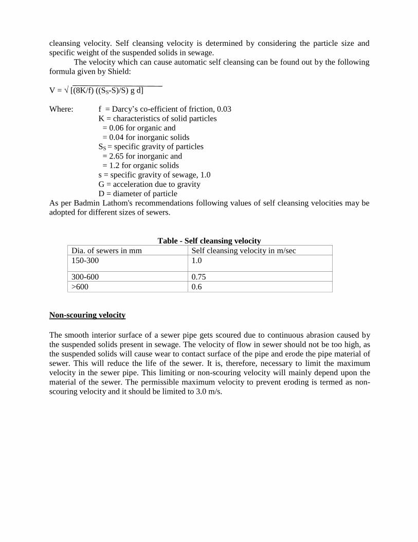
As per Badmin Lathom's recommendations following values of self cleansing velocities may be adopted for different sizes of sewers.
Table - Self cleansing velocity
Dia. of sewers in mm
Self cleansing velocity in m/sec
150-300
1.0
300-600
0.75
>600
0.6
Non-scouring velocity
The smooth interior surface of a sewer pipe gets scoured due to continuous abrasion caused by
the suspended solids present in sewage. The velocity of flow in sewer should not be too high, as
the suspended solids will cause wear to contact surface of the pipe and erode the pipe material of
sewer. This will reduce the life of the sewer. It is, therefore, necessary to limit the maximum
velocity in the sewer pipe. This limiting or non-scouring velocity will mainly depend upon the
material of the sewer. The permissible maximum velocity to prevent eroding is termed as non-
scouring velocity and it should be limited to 3.0 m/s.
3. Briefly explain the terms : i) Infiltration and Exfiltration. ( Dec 13/Jan 14) Answer:
Infiltration cause increases to the “legitimate” flows in urban sewerage systems. Infiltration
represents a slow response process resulting in increased flows mainly due to seasonally-elevated
groundwater entering the drainage system, and primarily occurring through defects in the pipe
network.
Exfiltration represents losses from the sewer pipe, resulting in reduced conveyance flows and is
due to leaks from defects in the sewer pipe walls as well as overflow discharge into manholes,
chambers and connecting surface water pipes. The physical defects are due to a combination of
factors including poor construction and pipe joint fittings, root penetration, illicit connections,
biochemical corrosion, soil conditions and traffic loadings as well as aggressive groundwater.
It is clear that Infiltration and Exfiltration involve flows passing through physical defects in the
sewer fabric and they will often occur concurrently during fluctuations in groundwater levels,
and particularly in association with wet weather events; both of which can generate locally high
hydraulic gradients. Exfiltration losses are much less obvious and modest than infiltration gains,
and are therefore much more difficult to identify and quantify. However, being dispersed in
terms of their spatial distribution in the sewer pipe, exfiltration losses can have potentially
significant risks for groundwater quality. The episodic but persistent reverse “pumping” effect
of hydraulic gain and loss will inevitably lead to long term scouring of pipe surrounds and
foundations resulting in pipe collapse and even surface subsidence.
4. Explain the differences in the hydraulic design of water supply lines and sewer lines.
(June/July14)
Answer:
The hydraulic design of sewers, which mean finding out their cross-sections and gradients, is
generally carried out on the same lines that of the water supply pipes. However, there are two
major differences between the characteristics of flows in sewers and water supply pipes.
i) The water supply pipes carry pure water without containing any kind of suspended
particles, either organic or inorganic in nature. The sewage, on the other hand,
contains such particles in suspension and the heavier of these particles may settle
down at the bottom of the sewers, as and when the flow velocity reduces, thus
ultimately resulting in the clogging of the sewers. In order to avoid such clogging of
sewers, it is necessary that the sewer pipes be of such a size and laid at such a
gradient, as to generate self – cleansing velocities at different possible discharges.
ii) The water supply pipes carry water under pressure and hence, within certain limits
they may be carried up and down the hills and the valleys: whereas the sewer pipes
carry sewage as gravity conduits and therefore, must be laid at a continuous gradient
in the downward direction up to the discharge point.
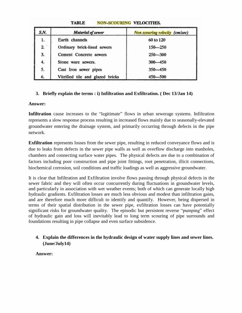
5. Give the expression for hydraulic elements of circular sewer when running half full
and partially full. (Dec-14/Jan 15)
Answer:
Hydraulic Characteristics of Circular Sewer Running half Full or Partially Full
Circular Sewer Running half Full HMD, R = A/P
Wetted Area, A= πD2/8
Wetted Perimeter, P= πD/2 Solving for half full sewer, R = D/4
Circular Sewer Running half Full or Partially Full
6. Explain the different shapes of sewers and their applications on the field with neat
sketches. (June 13/July 14)
Answer:
1. Box or rectangular type sewers
In olden days these sewers were constructed by laying concrete at bottom and
constructing the sides with masonry. But now a day‟s masonry has been completely replaced by
concrete. These are mainly used for out fall sewers. They have got relatively high hydraulic
mean depth at large flows and therefore can have higher velocities when laid to the same slope as
that of a circular or egg-shared sewer. They are therefore most suitable for large size storm
sewers.
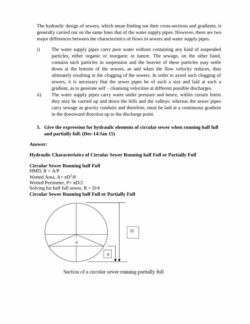
2. Egg-shared sewers
These are shown in figure. This share has got better hydraulic properties, but it is costly.
Firstly due to longer perimeter more material for construction is required and secondly because
of its odd shape it is difficult to construct. This sewer requires always a good foundation and
proper reinforcement to make structurally stable. In India they are rarely used. They are most
suitable in care of combined sewers.
The main advantage of this sewer is that it gives a slightly higher velocity during low
flow, than a circular sewer of the same size.
Standard Egg Shaped Sewer
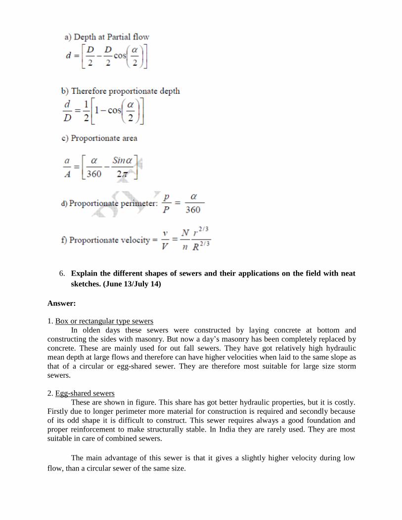
New/ Modified Egg shaped Sewer
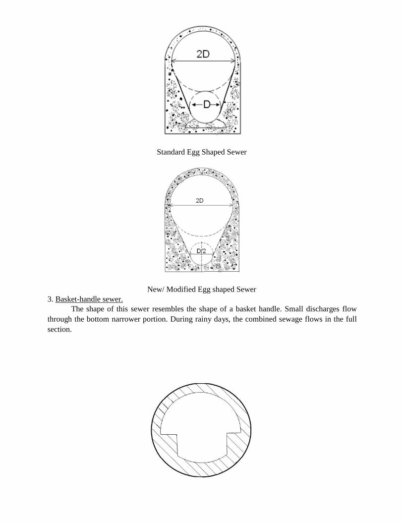
3. Basket-handle sewer.
The shape of this sewer resembles the shape of a basket handle. Small discharges flow
through the bottom narrower portion. During rainy days, the combined sewage flows in the full
section.
Basket-Handle Section
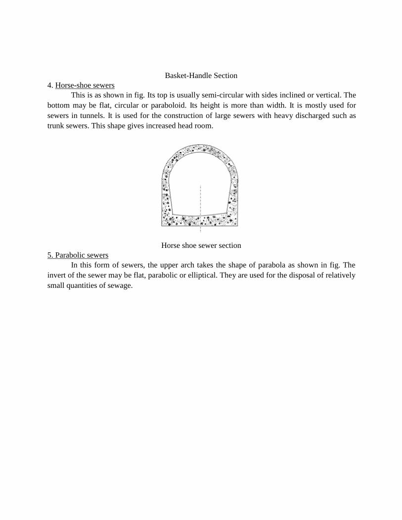
4. Horse-shoe sewers
This is as shown in fig. Its top is usually semi-circular with sides inclined or vertical. The
bottom may be flat, circular or paraboloid. Its height is more than width. It is mostly used for
sewers in tunnels. It is used for the construction of large sewers with heavy discharged such as
trunk sewers. This shape gives increased head room.
Horse shoe sewer section
5. Parabolic sewers
In this form of sewers, the upper arch takes the shape of parabola as shown in fig. The
invert of the sewer may be flat, parabolic or elliptical. They are used for the disposal of relatively
small quantities of sewage.
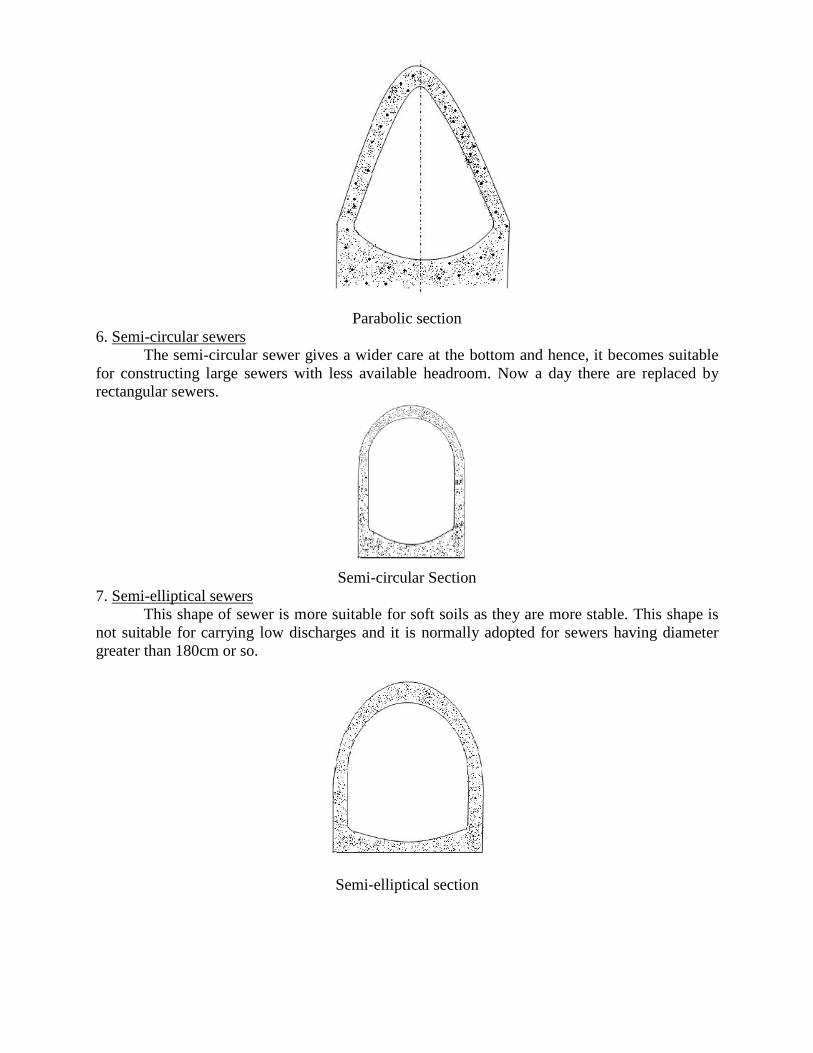
Parabolic section
6. Semi-circular sewers
The semi-circular sewer gives a wider care at the bottom and hence, it becomes suitable
for constructing large sewers with less available headroom. Now a day there are replaced by
rectangular sewers.
Semi-circular Section
7. Semi-elliptical sewers
This shape of sewer is more suitable for soft soils as they are more stable. This shape is
not suitable for carrying low discharges and it is normally adopted for sewers having diameter
greater than 180cm or so.
Semi-elliptical section
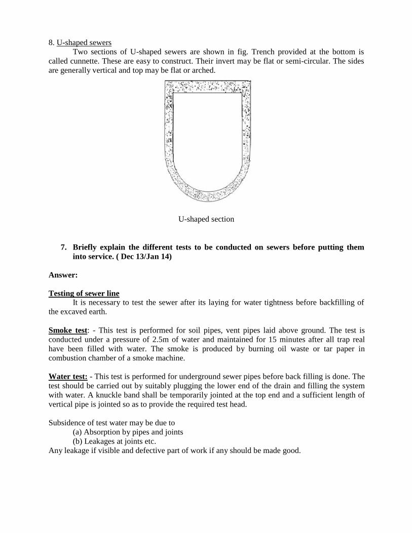
8. U-shaped sewers
Two sections of U-shaped sewers are shown in fig. Trench provided at the bottom is
called cunnette. These are easy to construct. Their invert may be flat or semi-circular. The sides
are generally vertical and top may be flat or arched.
U-shaped section
7. Briefly explain the different tests to be conducted on sewers before putting them
into service. ( Dec 13/Jan 14)
Answer:
Testing of sewer line It is necessary to test the sewer after its laying for water tightness before backfilling of
the excaved earth.
Smoke test: - This test is performed for soil pipes, vent pipes laid above ground. The test is
conducted under a pressure of 2.5m of water and maintained for 15 minutes after all trap real
have been filled with water. The smoke is produced by burning oil waste or tar paper in
combustion chamber of a smoke machine.
Water test: - This test is performed for underground sewer pipes before back filling is done. The
test should be carried out by suitably plugging the lower end of the drain and filling the system
with water. A knuckle band shall be temporarily jointed at the top end and a sufficient length of
vertical pipe is jointed so as to provide the required test head.
Subsidence of test water may be due to
(a) Absorption by pipes and joints
(b) Leakages at joints etc.
Any leakage if visible and defective part of work if any should be made good.
Test for straightness and obstruction: - For this test, a mirror is placed in front of one end of
sewer and the image of the section is observed. If the sewer line is straight, the image should be
circular. If it is not a complete circle, then it is not straight.
For testing for obstruction, by inserting a steel call
at upper end and if there is no obstruction in the sewer line, the call will emerge out from the
lower end.
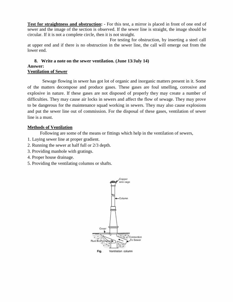
8. Write a note on the sewer ventilation. (June 13/July 14)
Answer:
Ventilation of Sewer
Sewage flowing in sewer has got lot of organic and inorganic matters present in it. Some
of the matters decompose and produce gases. These gases are foul smelling, corrosive and
explosive in nature. If these gases are not disposed of properly they may create a number of
difficulties. They may cause air locks in sewers and affect the flow of sewage. They may prove
to be dangerous for the maintenance squad working in sewers. They may also cause explosions
and put the sewer line out of commission. For the disposal of these gases, ventilation of sewer
line is a must.
Methods of Ventilation
Following are some of the means or fittings which help in the ventilation of sewers,
1. Laying sewer line at proper gradient.
2. Running the sewer at half full or 2/3 depth.
3. Providing manhole with gratings.
4. Proper house drainage.
5. Providing the ventilating columns or shafts.
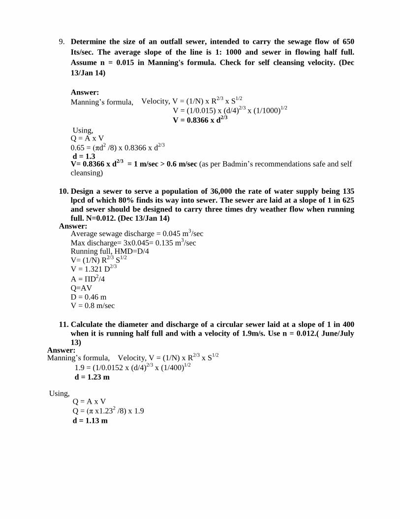
9. Determine the size of an outfall sewer, intended to carry the sewage flow of 650
Its/sec. The average slope of the line is 1: 1000 and sewer in flowing half full.
Assume n = 0.015 in Manning's formula. Check for self cleansing velocity. (Dec
13/Jan 14)
Answer:
Manning‟s formula,
Velocity, V = (1/N) x R2/3
x S1/2
V = (1/0.015) x (d/4)2/3
x (1/1000)1/2
V = 0.8366 x d2/3
Using, Q = A x V
0.65 = (πd2
/8) x 0.8366 x d2/3
d = 1.3 V= 0.8366 x d
2/3 = 1 m/sec > 0.6 m/sec (as per Badmin‟s recommendations safe and self
cleansing)
10. Design a sewer to serve a population of 36,000 the rate of water supply being 135
lpcd of which 80% finds its way into sewer. The sewer are laid at a slope of 1 in 625
and sewer should be designed to carry three times dry weather flow when running
full. N=0.012. (Dec 13/Jan 14) Answer:
Average sewage discharge = 0.045 m3/sec
Max discharge= 3x0.045= 0.135 m3/sec
Running full, HMD=D/4
V= (1/N) R2/3
S1/2
V = 1.321 D2/3
A = ΠD2/4
Q=AV
D = 0.46 m V = 0.8 m/sec
11. Calculate the diameter and discharge of a circular sewer laid at a slope of 1 in 400
when it is running half full and with a velocity of 1.9m/s. Use n = 0.012.( June/July
13) Answer: Manning‟s formula, Velocity, V = (1/N) x R
2/3 x S
1/2
1.9 = (1/0.0152 x (d/4)2/3
x (1/400)1/2
d = 1.23 m
Using, Q = A x V
Q = (π x1.232
/8) x 1.9
d = 1.13 m
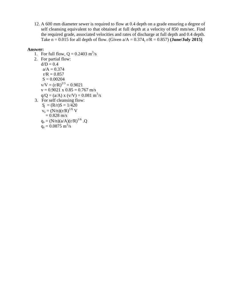
12. A 600 mm diameter sewer is required to flow at 0.4 depth on a grade ensuring a degree of
self cleansing equivalent to that obtained at full depth at a velocity of 850 mm/sec. Find
the required grade, associated velocities and rates of discharge at full depth and 0.4 depth.
Take n = 0.015 for all depth of flow. (Given a/A = 0.374, r/R = 0.857) (June/July 2015)
Answer: 1. For full flow, Q = 0.2403 m
3/s
2. For partial flow:
d/D = 0.4 a/A = 0.374 r/R = 0.857 S = 0.00204
v/V = (r/R)2/3
= 0.9021 v = 0.9021 x 0.85 = 0.767 m/s
q/Q = (a/A) x (v/V) = 0.081 m3/s
3. For self cleansing flow: S = (R/r)S = 1/420
vs = (N/n)(r/R)1/6
V = 0.828 m/s
qs = (N/n)(a/A)(r/R)1/6
.Q
qs = 0.0875 m /s
s
3
QUESTIONS AND ANSWERS
PART-A
UNIT-III
1. What are sewer appurtenances? List them and explain with a neat sketch any one of
them. (June/July 14, June/July 2015)
Answer: SEWER APPURTENANCES
Sewage flowing in the sewer line contains a large number of impurities in the form of silt,
fats, oils, rags etc. Under normal flows they are not likely to settle and choke the sewers, but
during small flows self-cleansing velocity is not likely to develop and the chances of choking of
the sewers are increased. Chokings have to be removed time to time, and facilities should be
provided on the sewer lines for this purpose. Therefore, for proper functioning and to facilitate
maintenance of the sewage system, various additional structures have to be constructed on the
sewer lines. These structures are known as sewer appurtenances. Following are the important
appurtenances,
1. Manholes
2. Inlets
3. Catch basins
4. Flushing devices
5. Regulators
6. Inverted siphons
7. Grease and oil traps
8. Lamp holes
9. Leaping weirs
10. Junction chambers
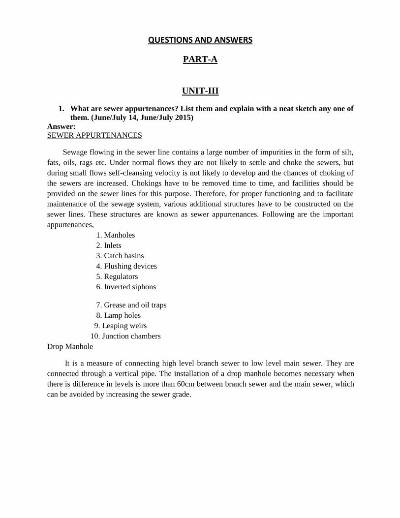
Drop Manhole
It is a measure of connecting high level branch sewer to low level main sewer. They are
connected through a vertical pipe. The installation of a drop manhole becomes necessary when
there is difference in levels is more than 60cm between branch sewer and the main sewer, which
can be avoided by increasing the sewer grade.
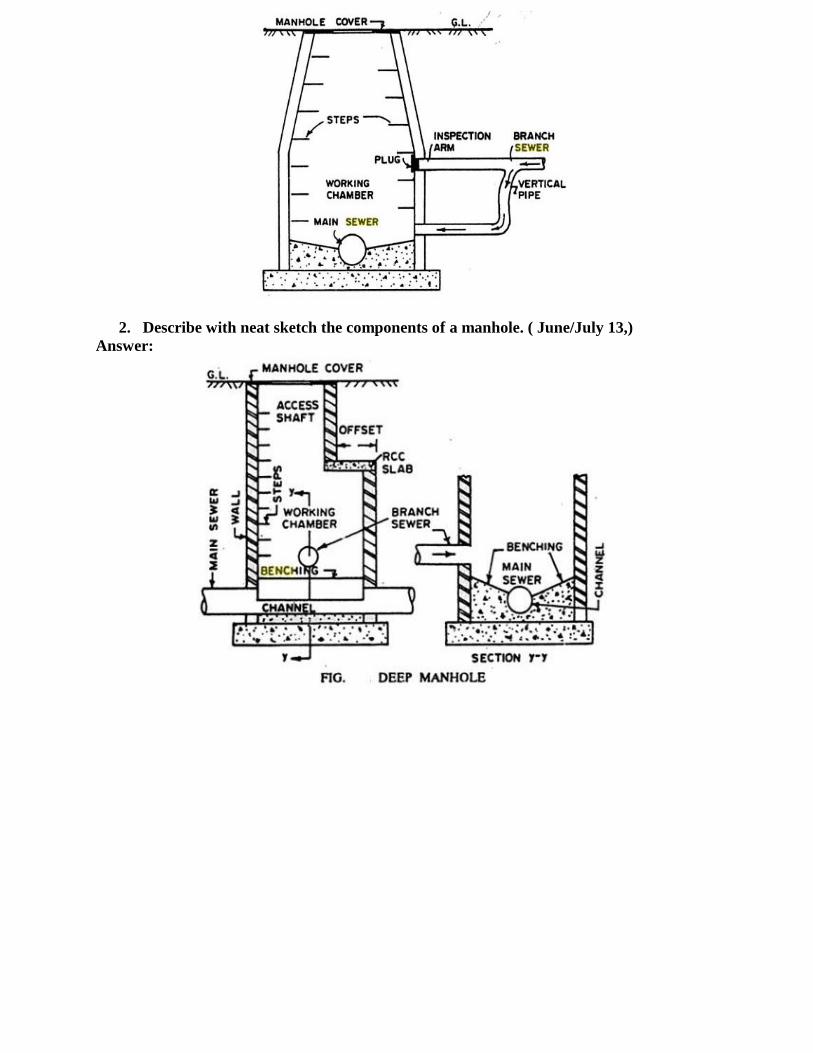
2. Describe with neat sketch the components of a manhole. ( June/July 13,)
Answer:
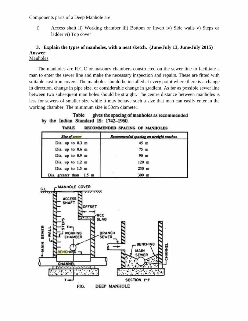
Components parts of a Deep Manhole are:
i) Access shaft ii) Working chamber iii) Bottom or Invert iv) Side walls v) Steps or
ladder vi) Top cover
3. Explain the types of manholes, with a neat sketch. (June/July 13, June/July 2015)
Answer: Manholes
The manholes are R.C.C or masonry chambers constructed on the sewer line to facilitate a
man to enter the sewer line and make the necessary inspection and repairs. These are fitted with
suitable cast iron covers. The manholes should be installed at every point where there is a change
in direction, change in pipe size, or considerable change in gradient. As far as possible sewer line
between two subsequent man holes should be straight. The centre distance between manholes is
less for sewers of smaller size while it may behave such a size that man can easily enter in the
working chamber. The minimum size is 50cm diameter.
4. Explain the following with sketches: i) Catch basins ii) Oil and grease traps.
(Dec 14/Jan 15)
Answer:
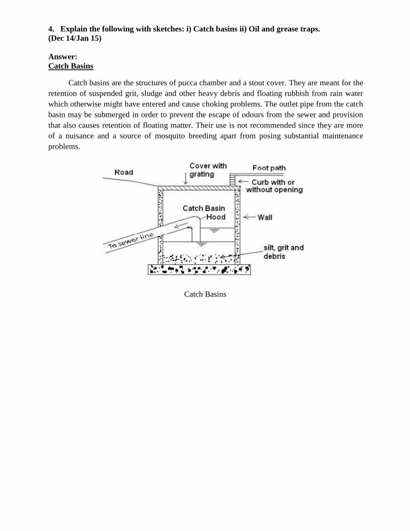
Catch Basins
Catch basins are the structures of pucca chamber and a stout cover. They are meant for the
retention of suspended grit, sludge and other heavy debris and floating rubbish from rain water
which otherwise might have entered and cause choking problems. The outlet pipe from the catch
basin may be submerged in order to prevent the escape of odours from the sewer and provision
that also causes retention of floating matter. Their use is not recommended since they are more
of a nuisance and a source of mosquito breeding apart from posing substantial maintenance
problems.
Catch Basins
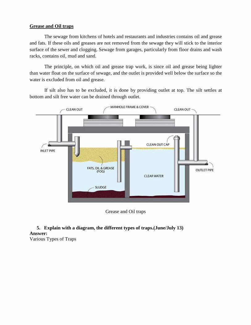
Grease and Oil traps
The sewage from kitchens of hotels and restaurants and industries contains oil and grease
and fats. If these oils and greases are not removed from the sewage they will stick to the interior
surface of the sewer and clogging. Sewage from garages, particularly from floor drains and wash
racks, contains oil, mud and sand.
The principle, on which oil and grease trap work, is since oil and grease being lighter
than water float on the surface of sewage, and the outlet is provided well below the surface so the
water is excluded from oil and grease.
If silt also has to be excluded, it is done by providing outlet at top. The silt settles at
bottom and silt free water can be drained through outlet.
Grease and Oil traps
5. Explain with a diagram, the different types of traps.(June/July 13) Answer: Various Types of Traps
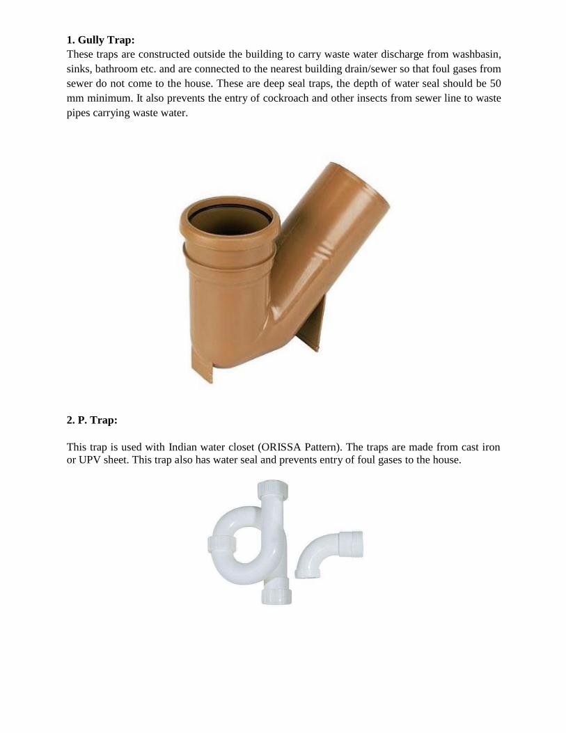
1. Gully Trap:
These traps are constructed outside the building to carry waste water discharge from washbasin,
sinks, bathroom etc. and are connected to the nearest building drain/sewer so that foul gases from
sewer do not come to the house. These are deep seal traps, the depth of water seal should be 50
mm minimum. It also prevents the entry of cockroach and other insects from sewer line to waste
pipes carrying waste water.
2. P. Trap:
This trap is used with Indian water closet (ORISSA Pattern). The traps are made from cast iron
or UPV sheet. This trap also has water seal and prevents entry of foul gases to the house.
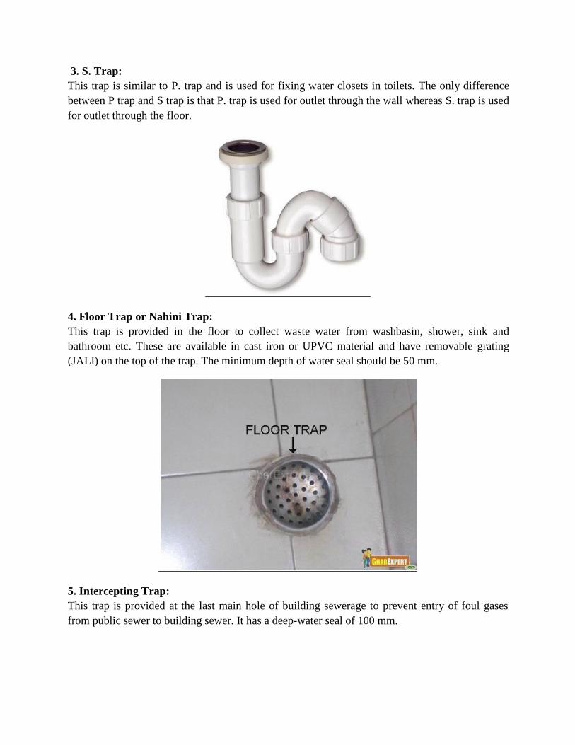
3. S. Trap:
This trap is similar to P. trap and is used for fixing water closets in toilets. The only difference
between P trap and S trap is that P. trap is used for outlet through the wall whereas S. trap is used
for outlet through the floor.
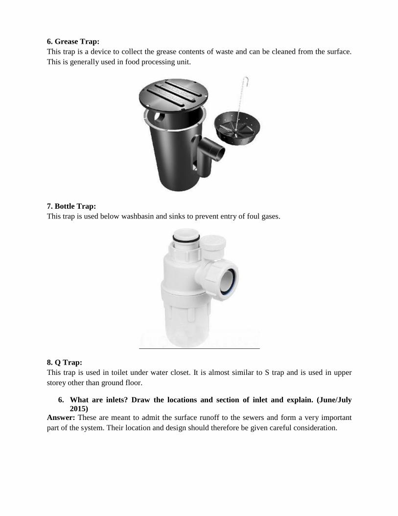
4. Floor Trap or Nahini Trap:
This trap is provided in the floor to collect waste water from washbasin, shower, sink and
bathroom etc. These are available in cast iron or UPVC material and have removable grating
(JALI) on the top of the trap. The minimum depth of water seal should be 50 mm.
5. Intercepting Trap:
This trap is provided at the last main hole of building sewerage to prevent entry of foul gases
from public sewer to building sewer. It has a deep-water seal of 100 mm.
6. Grease Trap:
This trap is a device to collect the grease contents of waste and can be cleaned from the surface.
This is generally used in food processing unit.
7. Bottle Trap:
This trap is used below washbasin and sinks to prevent entry of foul gases.
8. Q Trap:
This trap is used in toilet under water closet. It is almost similar to S trap and is used in upper
storey other than ground floor.
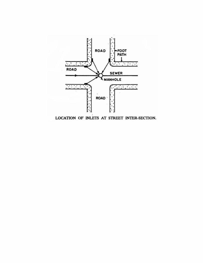
6. What are inlets? Draw the locations and section of inlet and explain. (June/July
2015) Answer: These are meant to admit the surface runoff to the sewers and form a very important
part of the system. Their location and design should therefore be given careful consideration.
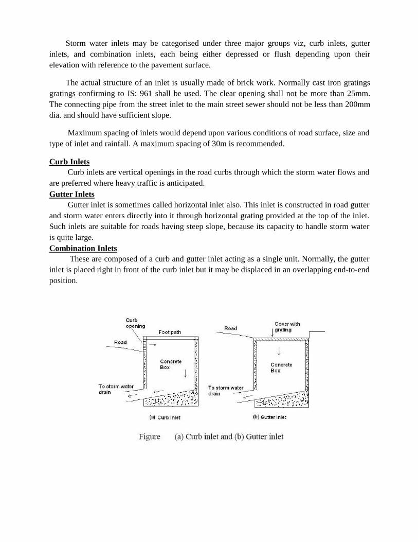
Storm water inlets may be categorised under three major groups viz, curb inlets, gutter
inlets, and combination inlets, each being either depressed or flush depending upon their
elevation with reference to the pavement surface.
The actual structure of an inlet is usually made of brick work. Normally cast iron gratings
gratings confirming to IS: 961 shall be used. The clear opening shall not be more than 25mm.
The connecting pipe from the street inlet to the main street sewer should not be less than 200mm
dia. and should have sufficient slope.
Maximum spacing of inlets would depend upon various conditions of road surface, size and
type of inlet and rainfall. A maximum spacing of 30m is recommended.
Curb Inlets
Curb inlets are vertical openings in the road curbs through which the storm water flows and
are preferred where heavy traffic is anticipated.
Gutter Inlets
Gutter inlet is sometimes called horizontal inlet also. This inlet is constructed in road gutter
and storm water enters directly into it through horizontal grating provided at the top of the inlet.
Such inlets are suitable for roads having steep slope, because its capacity to handle storm water
is quite large.
Combination Inlets
These are composed of a curb and gutter inlet acting as a single unit. Normally, the gutter
inlet is placed right in front of the curb inlet but it may be displaced in an overlapping end-to-end
position.
QUESTIONS AND ANSWERS
PART-A
UNIT-IV
1. Differentiate between fresh sewage, stale sewage and septic sewage. (June/July 2015)
Answer: The character of sewage changes with its age and its opportunities to undergo bacterial
action. THE DISTINCTION BETWEEN FRESH, STALE AND SEPTIC SEWAGE.
Fresh sewage usually contains free oxygen and nitrogen in the form of nitrites, and nitrates,
together with a relatively large proportion of organic matter in suspension.
Stale sewage is sewage in that state when the carbon, through bacterial agency in the presence of
free oxygen is oxidized, nitrogen and hydrogen unite to form ammonia, which uniting with the
carbonic acid, forms ammonium carbonate. Under the influence of the mechanical and bacterial
forces acting upon it, the dissolved organic matter is finally exhausted, but up to this point free
ammonia increases, while crude organic matter decreases. We designate it as stale sewage from
which the free oxygen has just become exhausted and free ammonia increased to the possible
maximum by the exhaustion of the oxygen.
After the oxygen is exhausted, the bacteria still continue to be active and chemical changes goes
on, breaking up organic matter into simpler forms. While sewage containing free oxygen has not
a particularly of offensive odor, after the oxygen is exhausted, sewage become very ill-smelling,
because of the generation and escape of hydrogen compounds of carbon, sulphur and
phosphorous. The result of these changes is to decrease the amount of carbonaceous and
nitrogenous matter in the sewage. Sewage in this state is known as septic sewage.
2. Explain COD and its relation with BOD. (June/July 2015)
Answer: Chemical oxygen demand (COD) It is the oxygen equivalent of organic matter. It is determined by measuring the dissolved oxygen
used during the chemical oxidation of organic matter in 3 hours.
Difference between BOD and COD BOD (Biochemical oxygen demand) - The amount of oxygen required by micro-organisms to
degrade the organic matter and can be calculated as BOD of diluted and undiluted samples. The
BOD value depends on the dissolved organic matter in the waste water samples. More the
organic matter, more the demand of oxygen by microbes to degrade it.
Whereas as COD (Chemical Oxygen Demand) - In this process, Use of strong chemical agent
(such as potassium dichromate) is done to degrade both the organic as well as inorganic matter
present in the wastewater samples. Also, COD values are always higher than the BOD values,
because COD includes both bio-degradable and non-biodegradable substances whereas BOD
contains only bio-degradable.
3. What is treatability Index? What is the use of treatability index? (June/July 2015)
Answer:
It is possible to correlate BOD and COD. BOD5/COD ratio is called Treatability /
Biodegradability Index and varies from 0.4 to 0.8 for domestic wastewaters.
If BOD/COD is > 0.6 then the waste is fairly biodegradable and can be effectively treated
biologically.
If BOD/COD ratio is between 0.3 and 0.6, then seeding is required to treat it biologically.
If BOD/COD is < 0.3 then it cannot be treated biologically.
4. Explain the physical and chemical characteristics of sewage. (June/July 13)
Answer:
Physical and chemicals characteristics /properties of wastewater
Characteristic Sources Physical properties: Domestic and industrial wastes, natural decay of organic materials
Color
Odor Decomposing wastewater, industrial wastes.
Solids Domestic water supply, domestic and industrial wastes, soil erosion,
inflow infiltration
Temperature
Chemical
constituents:
Organic:
Carbohydrates
Fats, oils, and grease
Pesticides
Phenols
Protein
s
Priority pollutants
Surfactants
Volatile organic
compounds
Other
Inorganic:
Aikalinity
Chlorides
Heavy metals
Nitrogen
PH
Phosphorus
Priority polluter
Sulfur
Gases:
Hydrogen sulfide
Methane Oxygen
Domestic and industrial wastes
Domestic, commercial, and industrial wastes
Domestic, commercial, and industrial wastes
Agricultural wastes
Industrial wastes
Domestic, commercial, and industrial wastes
Domestic, commercial, and industrial wastes
Domestic, commercial, and industrial wastes
Domestic, commercial, and industrial wastes
Natural decay of organic materials
Domestic wastes, domestic water supply, groundwater infiltration
Domestic wastes, domestic water supply, groundwater infiltration
Industrial wastes
Domestic and agricultural wastes
Domestic, commercial, and industrial wastes
Domestic, commercial, and industrial wastes natural runoff
Domestic water supply; doestic, commercial. And industrial wastes
Decomposition of domestic wastes
Decomposition of domestic wastes Domestic water supply , surface-water infiltration
Physical characteristics-Temperature
Temperature of wastewater is commonly higher than that of water supply. Depending on the
geographic location the mean annual temperature varies in the range of 10 to 21oC with an
average of 16oC.
Importance of temperature:-
Affects chemical reactions during the wastewater treatment process.
Affects aquatic life.
Oxygen solubility is less in worm water than cold water. Optimum temperature for bacterial
activity is in the range of 25°C to 350C. Aerobic digestion and nitrification stop when the
temperature rises to 50oC. When the temperature drops to about 15°c, methane producing
bacteria become in active. Nitrifying bacteria stop activity at about 5°c.
Color:-
Fresh waste water- light brownish gray.
With time -dark gray
More time- black (septic).
Sometimes - pink due to algae or due to industrial colors.
Turbidity:- It's a measure of the light –transmitting properties of water.
Chemical characteristics of wastewater:- Points of concern regarding the chemical characteristics of wastewater are:
-Organic matter -Measurements of organic matter
-Inorganic matter
-Gases -pH
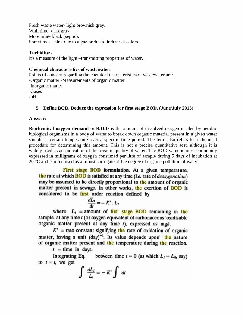
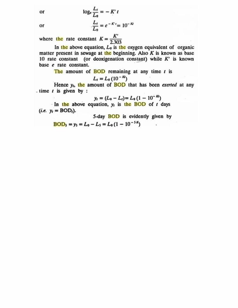
5. Define BOD. Deduce the expression for first stage BOD. (June/July 2015) Answer:
Biochemical oxygen demand or B.O.D is the amount of dissolved oxygen needed by aerobic
biological organisms in a body of water to break down organic material present in a given water
sample at certain temperature over a specific time period. The term also refers to a chemical
procedure for determining this amount. This is not a precise quantitative test, although it is
widely used as an indication of the organic quality of water. The BOD value is most commonly
expressed in milligrams of oxygen consumed per litre of sample during 5 days of incubation at
20 °C and is often used as a robust surrogate of the degree of organic pollution of water.
6. Clearly bring out the differences between the following terms: i) Aerobic and
anaerobic decomposition ii) BOD and COD iii) Carbonaceous BOD and
Nitrogenous BOD. (June/July 13)
Answer: i) Aerobic and anaerobic decomposition
Aerobic Decomposition A biological process, in which, organisms use available organic matter to support biological
activity. The process uses organic matter, nutrients, and dissolved oxygen, and produces stable
solids, carbon dioxide, and more organisms. The microorganisms which can only survive in
aerobic conditions are known as aerobic organisms. In sewer lines the sewage becomes anoxic if
left for a few hours and becomes anaerobic if left for more than 1 1/2 days. Anoxic organisms
work well with aerobic and anaerobic organisms. Facultative and anoxic are basically the same
concept.
Anaerobic Decomposition A biological process, in which, decomposition of organic matter occurs without oxygen. Two
processes occur during anaerobic decomposition. First, facultative acid forming bacteria use
organic matter as a food source and produce volatile (organic) acids, gases such as carbon
dioxide and hydrogen sulfide, stable solids and more facultative organisms. Second, anaerobic
methane formers use the volatile acids as a food source and produce methane gas, stable solids
and more anaerobic methane formers. The methane gas produced by the process is usable as a
fuel. The methane former works slower than the acid former, therefore the pH has to stay
constant consistently, slightly basic, to optimize the creation of methane. You need to constantly
feed it sodium bicarbonate to keep it basic.
ii) BOD and COD
Biochemical oxygen demand or B.O.D
It is the amount of dissolved oxygen needed by aerobic biological organisms in a body of water
to break down organic material present in a given water sample at certain temperature over a
specific time period. The term also refers to a chemical procedure for determining this amount.
This is not a precise quantitative test, although it is widely used as an indication of the organic
quality of water. The BOD value is most commonly expressed in milligrams of oxygen
consumed per litre of sample during 5 days of incubation at 20 °C and is often used as a robust
surrogate of the degree of organic pollution of water.
Chemical oxygen demand (COD) It is the oxygen equivalent of organic matter. It is determined by measuring the dissolved oxygen
used during the chemical oxidation of organic matter in 3 hours.
iii) Carbonaceous BOD and Nitrogenous BOD.
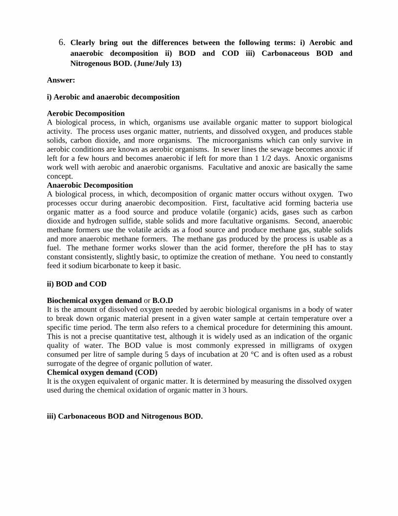
There are two stages of decomposition in the BOD test: a carbonaceous stage and a nitrogenous
stage.
The carbonaceous stage, or first stage, represents that portion of oxygen demand involved in the
conversion of organic carbon to carbon dioxide.
The nitrogenous stage, or second stage, represents a combined carbonaceous plus nitrogeneous
demand, when organic nitrogen, ammonia, and nitrite are converted to nitrate. Nitrogenous
oxygen demand generally begins after about 6 days. For some sewage, especially discharge from
wastewater treatment plants utilizing biological treatment processes, nitrification can occur in
less than 5 days if ammonia, nitrite, and nitrifying bacteria are present. In this case, a chemical
compound that prevents nitrification should be added to the sample if the intent is to measure
only the carbonaceous demand. The results are reported as carbonaceous BOD (CBOD), or as
CBOD5 when a nitrification inhibitor is used.
7. Explain the nitrogen cycle of decomposition of sewage. (Dec 14/Jan 15)
Answer:
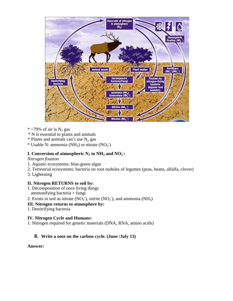
* ~79% of air is N2 gas * N is essential to plants and animals * Plants and animals can‟t use N gas
* Usable N: ammonia (NH3) or nitrate (NO3-)
I. Conversion of atmospheric N2 to NH3 and NO3-:
Nitrogen fixation
1. Aquatic ecosystems: blue-green algae 2. Terrestrial ecosystems: bacteria on root nodules of legumes (peas, beans, alfalfa, clover) 3. Lightening
II. Nitrogen RETURNS to soil by: 1. Decomposition of once living things
ammonifying bacteria + fungi
2. Exists in soil as nitrate (NO3-), nitrite (NO2
-), and ammonia (NH3)
III. Nitrogen returns to atmosphere by: 1. Denitrifying bacteria
IV. Nitrogen Cycle and Humans: 1. Nitrogen required for genetic materials (DNA, RNA, amino acids)
8. Write a note on the carbon cycle. (June /July 13)
Answer:
2
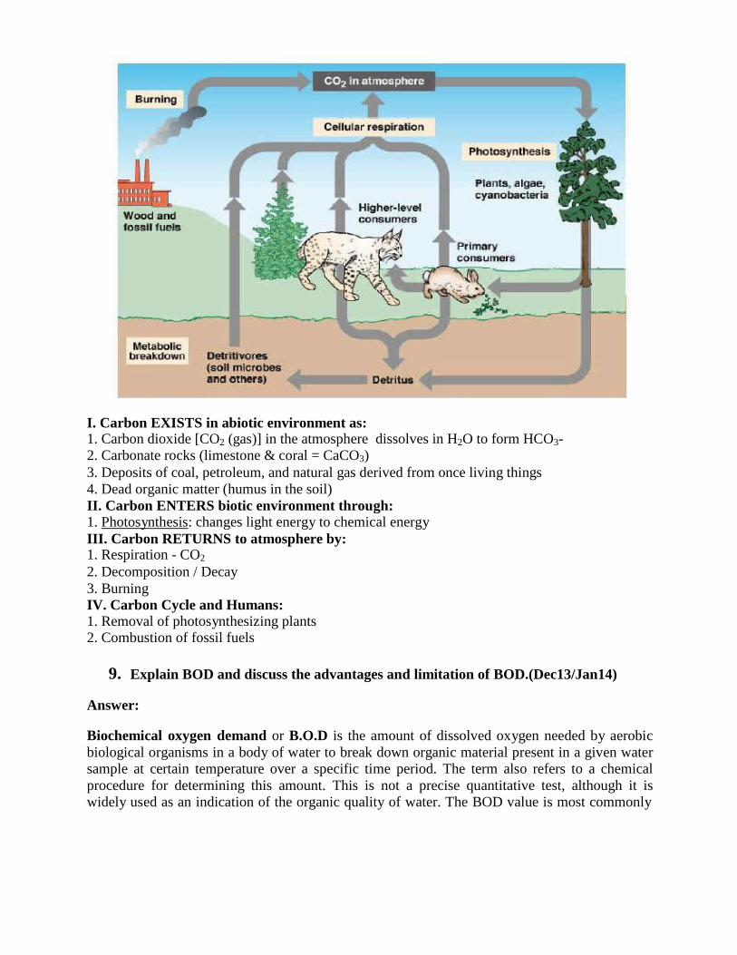
I. Carbon EXISTS in abiotic environment as: 1. Carbon dioxide [CO2 (gas)] in the atmosphere dissolves in H2O to form HCO3-
2. Carbonate rocks (limestone & coral = CaCO3)
3. Deposits of coal, petroleum, and natural gas derived from once living things
4. Dead organic matter (humus in the soil)
II. Carbon ENTERS biotic environment through: 1. Photosynthesis: changes light energy to chemical energy
III. Carbon RETURNS to atmosphere by: 1. Respiration - CO2
2. Decomposition / Decay
3. Burning
IV. Carbon Cycle and Humans: 1. Removal of photosynthesizing plants 2. Combustion of fossil fuels
9. Explain BOD and discuss the advantages and limitation of BOD.(Dec13/Jan14)
Answer:
Biochemical oxygen demand or B.O.D is the amount of dissolved oxygen needed by aerobic
biological organisms in a body of water to break down organic material present in a given water
sample at certain temperature over a specific time period. The term also refers to a chemical
procedure for determining this amount. This is not a precise quantitative test, although it is
widely used as an indication of the organic quality of water. The BOD value is most commonly
expressed in milligrams of oxygen consumed per litre of sample during 5 days of incubation at
20 °C and is often used as a robust surrogate of the degree of organic pollution of water.
BOD5 is the oxygen equivalent of organic matter. It is determined by measuring the dissolved oxygen used by microorganisms during the biochemical oxidation of organic matter in 5 days at
20oC.
Advantages: Used as a measurement of waste strength
- is an effluent discharge limitation parameter in mill permits
- Used as basis for designing & evaluating biological treatment systems
-to determine amount of Oxygen needed to stabilize organic matter in waste
-to determine size of wastewater treatment facilities -to measure efficiency of some treatment processes
Limitations of BOD5
Test period is too long not good for process control
• Only 60-70% of soluble organic matter is metabolized in five days
• Inorganic oxidation may also occur: 1. Inorganic oxidation of sulfur or iron:
S--
+ 2 O2 → SO4--
or 4Fe++
+ 3O2 → 2Fe2O3
2. Nitrification may also occur if ammonia is present Conversion of ammonia to nitrate:
NH3 + 2 O2 → HNO3 + H2O
10.What is meant by BOD and its determination in the laboratory with their standard
equations? (Dec 14/Jan 15)
Answer:
Biochemical oxygen demand or B.O.D is the amount of dissolved oxygen needed by aerobic
biological organisms in a body of water to break down organic material present in a given water
sample at certain temperature over a specific time period. The term also refers to a chemical
procedure for determining this amount. This is not a precise quantitative test, although it is
widely used as an indication of the organic quality of water. The BOD value is most commonly
expressed in milligrams of oxygen consumed per litre of sample during 5 days of incubation at
20 °C and is often used as a robust surrogate of the degree of organic pollution of water.
BOD determination in the laboratory
LABORATORY PROCEDURE
1. Completely fill two BOD bottles with dilution water.
2. Into additional BOD bottles, partially filled with dilution water, carefully measure out the
proper volume of sample. Add dilution water until the bottles are completely filled.
3. Stopper each bottle taking care to avoid trapping air bubbles inside the bottles as the bottle
stoppers are inserted.
4. Fill the top of each bottle neck around the stopper with dilution water.
5. Determine the initial DO content on one of each set of duplicate bottles, including the
dilution water blank by one of the approved methods and record data on the lab sheet.
6. Place the remaining bottles in the incubator at 20°C and incubate for five days.
7. At the end of exactly five days (+/-3 hours), test the DO content of the incubated bottles.
8. Calculate the BOD for each dilution. The most accurate BOD will be obtained from those
dilutions that have a depletion of at least 2 mg/L DO and at least 1.0 mg/L DO residual. If
there is more than one dilution that meets these criteria, the BOD results should be averaged
to obtain a final BOD value.
9. The dilution water blanks are used only to check the quality of the dilution water. If the
quality of the water is good and free from impurities, the depletion of DO should be less
than 0.2 mg/L. In any event, do not use the depletion obtained as a blank correction.
10. If nitrification inhibition is used, the BOD test must also be performed on a series of sample
dilutions which have not been inhibited.
11. Report the results of the nitrification inhibited samples as CBOD5 and uninhibited samples
as BOD5.
5 days 20°C BOD=(DOb – DOi) 100/% - (DOb – DOs)
DOb = Dissolved oxygen in blank solution
DOi = Dissolved oxygen in diluted sample after 5 days
DOs = Dissolved oxygen undiluted wastewater sample
11. Explain the concept of aerobic and anaerobic activity with respect to sewage
treatment. (Dec 13/Jan14)
Answer:
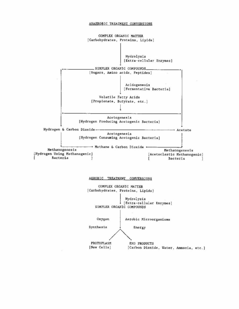
Microorganisms , like all living things, require food for growth . Biological sewage treatment
consists of a step-by-step, continuous, sequenced attack on the organic compounds found in
wastewater and upon which the microbes feed.
Aerobic Decomposition A biological process, in which, organisms use available organic matter to support biological
activity. The process uses organic matter, nutrients, and dissolved oxygen, and produces stable
solids, carbon dioxide, and more organisms. The microorganisms which can only survive in
aerobic conditions are known as aerobic organisms. In sewer lines the sewage becomes anoxic if
left for a few hours and becomes anaerobic if left for more than 1 1/2 days. Anoxic organisms
work well with aerobic and anaerobic organisms. Facultative and anoxic are basically the same
concept.
Anaerobic Decomposition A biological process, in which, decomposition of organic matter occurs without oxygen. Two
processes occur during anaerobic decomposition. First, facultative acid forming bacteria use
organic matter as a food source and produce volatile (organic) acids, gases such as carbon
dioxide and hydrogen sulfide, stable solids and more facultative organisms. Second, anaerobic
methane formers use the volatile acids as a food source and produce methane gas, stable solids
and more anaerobic methane formers. The methane gas produced by the process is usable as a
fuel. The methane former works slower than the acid former, therefore the pH has to stay
constant consistently, slightly basic, to optimize the creation of methane. You need to constantly
feed it sodium bicarbonate to keep it basic.
Aerobic Digestion Aerobic digestion of waste is the natural biological degradation and purification process in which bacteria that thrive in oxygen-rich environments break down and digest the waste. During oxidation process, pollutants are broken down into carbon dioxide (CO2 ), water (H2O), nitrates,
sulphates and biomass (microorganisms). By operating the oxygen supply with aerators, the
process can be significantly accelerated. Of all the biological treatment methods, aerobic digestion is the most widespread process that is used throughout the world.
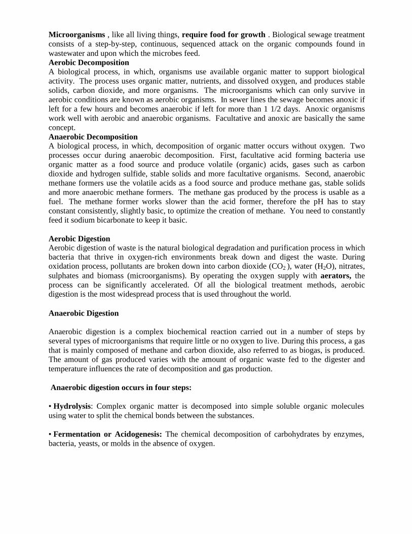
Anaerobic Digestion
Anaerobic digestion is a complex biochemical reaction carried out in a number of steps by
several types of microorganisms that require little or no oxygen to live. During this process, a gas
that is mainly composed of methane and carbon dioxide, also referred to as biogas, is produced.
The amount of gas produced varies with the amount of organic waste fed to the digester and
temperature influences the rate of decomposition and gas production.
Anaerobic digestion occurs in four steps:
• Hydrolysis: Complex organic matter is decomposed into simple soluble organic molecules
using water to split the chemical bonds between the substances.
• Fermentation or Acidogenesis: The chemical decomposition of carbohydrates by enzymes,
bacteria, yeasts, or molds in the absence of oxygen.
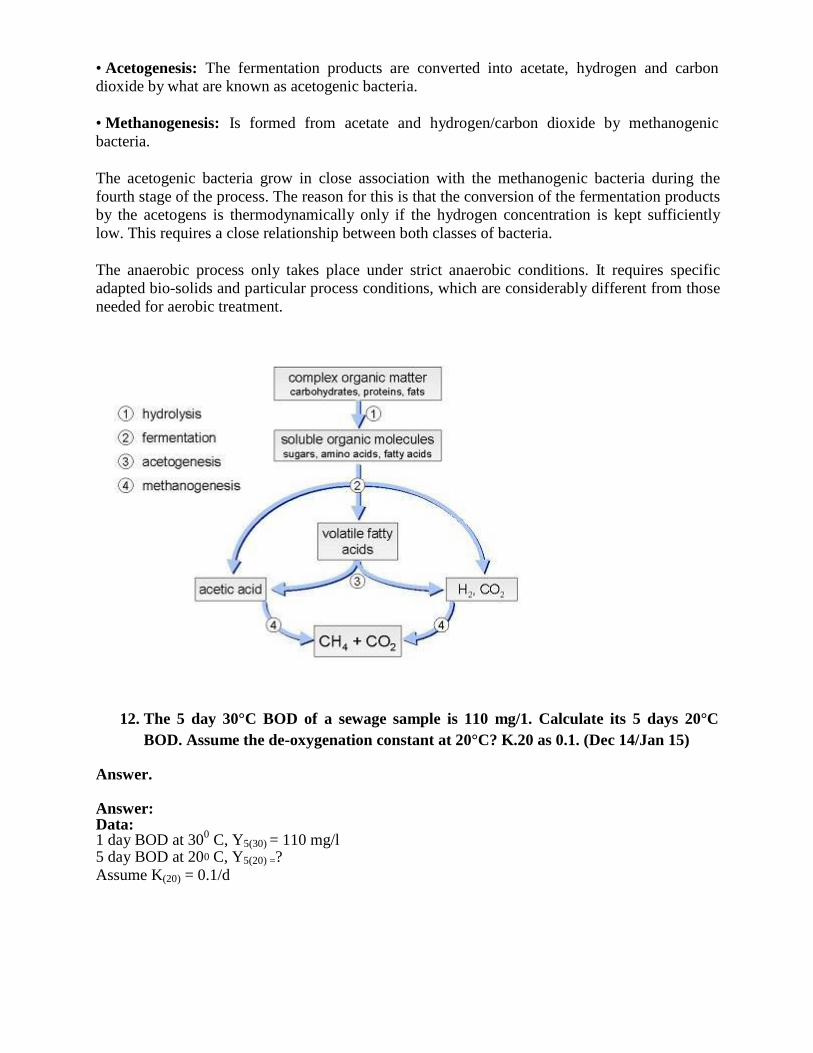
• Acetogenesis: The fermentation products are converted into acetate, hydrogen and carbon
dioxide by what are known as acetogenic bacteria.
• Methanogenesis: Is formed from acetate and hydrogen/carbon dioxide by methanogenic
bacteria.
The acetogenic bacteria grow in close association with the methanogenic bacteria during the
fourth stage of the process. The reason for this is that the conversion of the fermentation products
by the acetogens is thermodynamically only if the hydrogen concentration is kept sufficiently
low. This requires a close relationship between both classes of bacteria.
The anaerobic process only takes place under strict anaerobic conditions. It requires specific
adapted bio-solids and particular process conditions, which are considerably different from those
needed for aerobic treatment.
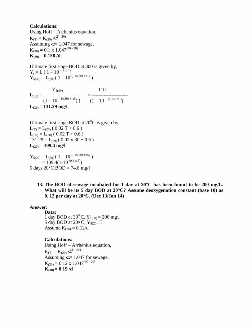
12. The 5 day 30°C BOD of a sewage sample is 110 mg/1. Calculate its 5 days 20°C
BOD. Assume the de-oxygenation constant at 20°C? K.20 as 0.1. (Dec 14/Jan 15)
Answer.
Answer: Data: 1 day BOD at 30
0 C, Y5(30) = 110 mg/l
5 day BOD at 20 C, Y5(20) =?
Assume K(20) = 0.1/d
0
Calculations: Using Hoff – Arrhenius equation,
K(T) = K(20) (T - 20)
Assuming с= 1.047 for sewage,
K(30) = 0.1 x 1.047(30 - 20)
K(30) = 0.158 /d
Ultimate first stage BOD at 300 is given by, Y = L ( 1 – 10
– k x t )
Y5(30) = L(30) ( 1 – 10 (– K(30) x t1)
)
Y1(30) L = -------------------------
(1 – 10 – K(30) x t5
) )
L(30) = 131.29 mg/l
110 = ----------------------
(1 – 10 – (0.158 x5)
)
Ultimate first stage BOD at 200C is given by,
L(T) = L(20) ( 0.02 T + 0.6 )
L(30) = L(20) ( 0.02 T + 0.6 )
131.29 = L(20) ( 0.02 x 30 + 0.6 )
L(20) = 109.4 mg/l
Y5(20) = L(20) ( 1 – 10 (– K(20) x t5)
)
= 109.4(1-10 ) 5 days 20°C BOD = 74.8 mg/l
13. The BOD of sewage incubated for 1 day at 30°C has been found to be 200 mg/L.
What will be its 5 day BOD at 20°C? Assume deoxygenation constant (base 10) as
0. 12 per day at 20°C. (Dec 13/Jan 14)
Answer: Data: 1 day BOD at 30
0 C, Y1(30) = 200 mg/l
5 day BOD at 20 C, Y5(20) =?
Assume K(20) = 0.12/d
Calculations:
Using Hoff – Arrhenius equation,
K(T) = K(20) (T - 20)
Assuming с= 1.047 for sewage,
K(30) = 0.12 x 1.047(30 - 20)
K(30) = 0.19 /d
с
t
(30)
-(0.1 x 5)
0
с
Ultimate first stage BOD at 300
is given by, Y = L ( 1 – 10
– k x t )
Y1(30) = L(30) ( 1 – 10 (– K(30) x t1)
)
Y1(30) L = -------------------------
(1 – 10 – K(30) x t1
) )
L(30) = 564.42 mg/l
200 = ----------------------
(1 – 10 – (0.19 x1)
)
Ultimate first stage BOD at 200C is given by,
L(T) = L(20) ( 0.02 T + 0.6 )
L(30) = L(20) ( 0.02 T + 0.6 )
564.42 = L(20) ( 0.02 x 30 + 0.6 )
L(20) = 470.35 mg/l
Y = L ( 1 – 10 (– K(20) x t5)
) = 470.35(1-10
-(0.12 x 5))
= 352.2 mg/l
14. The following observations were made in the laboratory on 2% dilution of waste
water :
D.O. of aerated dilution water - 7 mg/lt
D.O. of diluted sample after 5 days of incubation - 2 mg/lt
D.O. of original sample of waste water - 0.5 mg/lt.
Calculate the 5 day BOD of the sample and the ultimate first stage BOD, assuming
The deoxygenation rate constant at 20°C as 0.1. The test was conduct at 20°C. (June
/July 13)
Answer:
5 days 20°C BOD=(DOb – DOi) 100/% - (DOb – DOs)
DOb = Dissolved oxygen in blank solution = 7 mg/l
DOi = Dissolved oxygen in diluted sample after 5 days= 2 mg/l
DOs = Dissolved oxygen undiluted wastewater sample = 0.5 mg/l
5 days 20°C BOD= (7 – 2) 100/2 - (7 – 0.5)
5 days 20°C BOD = 243.5 mg/l
Y = L ( 1 – 10 (– K(20) x t5)
)
243.5 = L(20) ( 1 – 10 (– 0.1) x 5)
)
Ultimate first stage BOD at 200C = 356.11 mg/l
t
(30)
5(20) (20)
5(20) (20)
QUESTIONS AND ANSWERS
PART-B
UNIT-V
1. What is self purification phenomenon of streams? Discuss in brief, the various
natural forces effecting self-purification. (June/July 13, Dec 13/Jan 14, June/July
2015)
Answer:
SELF PURIFICATION OF NATURAL STREAMS
The automatic purification of natural water is known as self purification. The self purification of
natural water systems is a complex process that often involves physical, chemical, and biological
processes working simultaneously. The amount of dissolved Oxygen (DO) in water is one of the
most commonly used indicators of a river health. As DO drops below 4 or 5 mg/L the forms of
life that can survive begin to be reduced. A minimum of about 2.0 mg/L of dissolved oxygen is
required to maintain higher life forms. A number of factors affect the amount of DO available in
a river. Oxygen demanding wastes remove DO; plants add DO during day but remove it at night;
respiration of organisms removes oxygen. In summer, rising temperature reduces solubility of
oxygen, while lower flows reduce the rate at which oxygen enters the water from atmosphere.
Factors Affecting Self Purification
1. Dilution: When sufficient dilution water is available in the receiving water body, where the
waste water is discharged, the DO level in the receiving stream may not reach to zero or critical
DO due to availability of sufficient DO initially in the river water before receiving discharge of
wastewater.
2. Current: When strong water current is available, the discharged wastewater will be
thoroughly mixed with stream water preventing deposition of solids. In small current, the solid
matter from the wastewater will get deposited at the bed following decomposition and reduction
in DO.
3. Temperature: The quantity of DO available in stream water is more in cold temperature than
in hot temperature. Also, as the activity of microorganisms is more at the higher temperature,
hence, the self-purification will take less time at hot temperature than in winter.
4. Sunlight: Algae produces oxygen in presence of sunlight due to photosynthesis. Therefore,
sunlight helps in purification of stream by adding oxygen through photosynthesis.
5. Rate of Oxidation: Due to oxidation of organic matter discharged in the river DO depletion
occurs. This rate is faster at higher temperature and low at lower temperature. The rate of
oxidation of organic matter depends on the chemical composition of organic matter.
Oxygen Sag Curve
The oxygen sag or oxygen deficit in the stream at any point of time during self purification
process is the difference between the saturation DO content and actual DO content at that time.
The amount of resultant oxygen deflect can be obtained by algebraically adding the de -
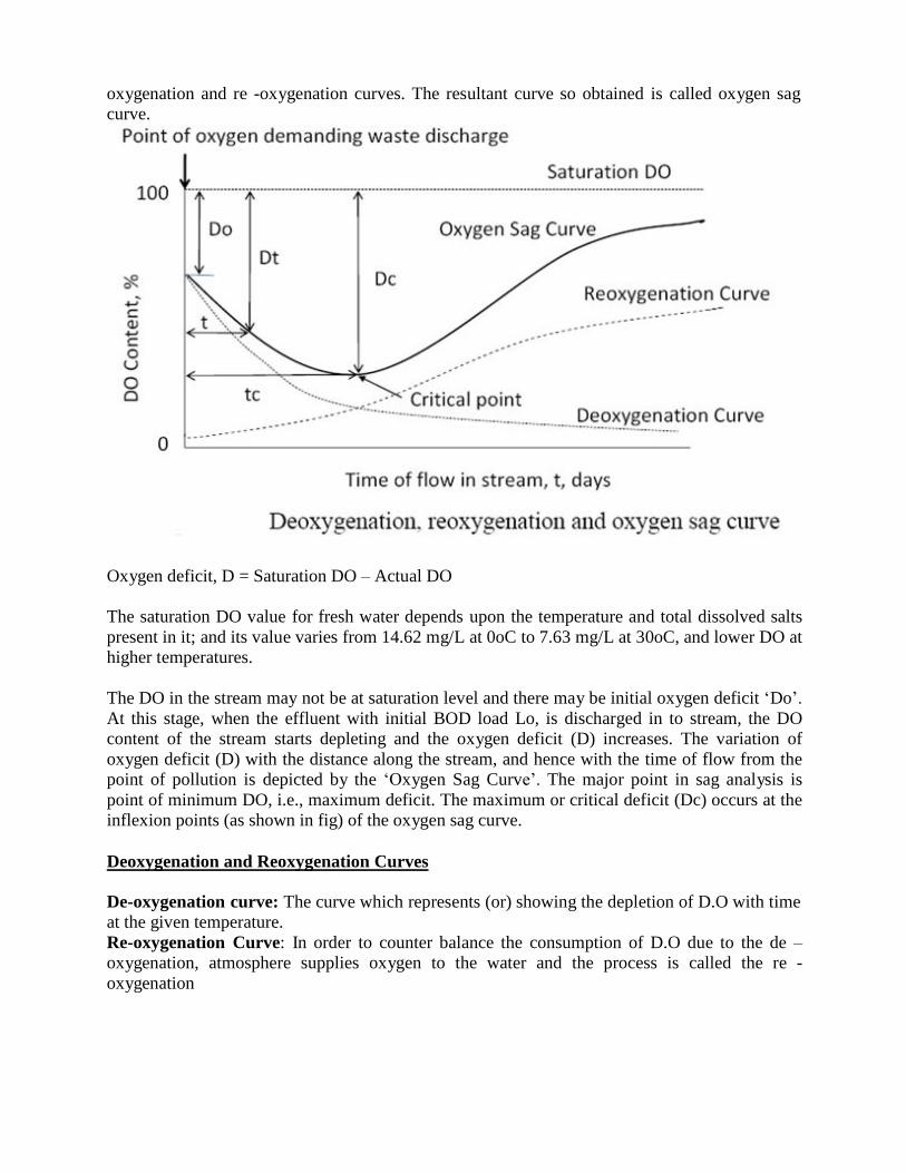
oxygenation and re -oxygenation curves. The resultant curve so obtained is called oxygen sag
curve.
Oxygen deficit, D = Saturation DO – Actual DO
The saturation DO value for fresh water depends upon the temperature and total dissolved salts
present in it; and its value varies from 14.62 mg/L at 0oC to 7.63 mg/L at 30oC, and lower DO at
higher temperatures.
The DO in the stream may not be at saturation level and there may be initial oxygen deficit „Do‟.
At this stage, when the effluent with initial BOD load Lo, is discharged in to stream, the DO
content of the stream starts depleting and the oxygen deficit (D) increases. The variation of
oxygen deficit (D) with the distance along the stream, and hence with the time of flow from the
point of pollution is depicted by the „Oxygen Sag Curve‟. The major point in sag analysis is
point of minimum DO, i.e., maximum deficit. The maximum or critical deficit (Dc) occurs at the
inflexion points (as shown in fig) of the oxygen sag curve.
Deoxygenation and Reoxygenation Curves
De-oxygenation curve: The curve which represents (or) showing the depletion of D.O with time
at the given temperature.
Re-oxygenation Curve: In order to counter balance the consumption of D.O due to the de –
oxygenation, atmosphere supplies oxygen to the water and the process is called the re -
oxygenation
When wastewater is discharged in to the stream, the DO level in the stream goes on depleting.
This depletion of DO content is known as deoxygenation. The rate of deoxygenation depends
upon the amount of organic matter remaining (Lt), to be oxidized at any time t, as well as
temperature (T) at which reaction occurs. The variation of depletion of DO content of the stream
with time is depicted by the deoxygenation curve in the absence of aeration. The ordinates below
the deoxygenation curve indicate the oxygen remaining in the natural stream after satisfying the
bio-chemical demand of oxygen. When the DO content of the stream is gradually consumed due
to BOD load, atmosphere supplies oxygen continuously to the water, through the process of re-
aeration or reoxygenation, i.e., along with deoxygenation, re-aeration is continuous process.
The rate of reoxygenation depends upon:
i) Depth of water in the stream: more for shallow depth.
ii) Velocity of flow in the stream: less for stagnant water.
iii) Oxygen deficit below saturation DO: since solubility rate depends on difference between
saturation concentration and existing concentration of DO.
iv) Temperature of water: solubility is lower at higher temperature and also saturation
concentration is less at higher temperature.
2. Explain wastewater disposal into sea. (June/July 2015) Answer:
Sea disposal can be an easy option where possible, and where strong currents and dilution
minimize the effects of the wastes. Disposing wastewater into the sea is still ongoing, despite the
severe environmental hazards. These may cause a decline in fish production rates and the
destruction of shellfish productive areas. Serious diseases can come as a result of an
environmental dysfunction.
Disposing wastewater in the sea is a crime to the environment, as it contains harmful organic
materials that affect the quality of the water, decreases oxygen levels in the water, and prevents
sunshine from penetrating, thus causing harm to marine life. Sewage is loaded with bacteria,
viruses, fungus and algae, that may lead to illness if the water is ingested accidentally.
Wastewater treatment stations can also become culprits when disposing untreated water that
exceeds the station‟s capacity. Sewage networks sometimes dispose water, legally or otherwise,
through drainage or groundwater networks.
3. Explain the different zones of self purification. (June /July 13)
Answer: Zones of Purification
When sewage is discharged into water, a succession of changes in water quality takes place. If
the sewage is emptied into a lake in which currents about the outfall are sluggish and shift their
direction with the wind, the changes occur in close proximity to each other and, as a result, the
pattern of changes is not crisply distinguished. If, on the other hand, the water moves steadily
away from the outfall, as in a stream, the successive changes occur in different river reaches and
establish a profile of pollution which is well defined. However, in most streams, this pattern is by
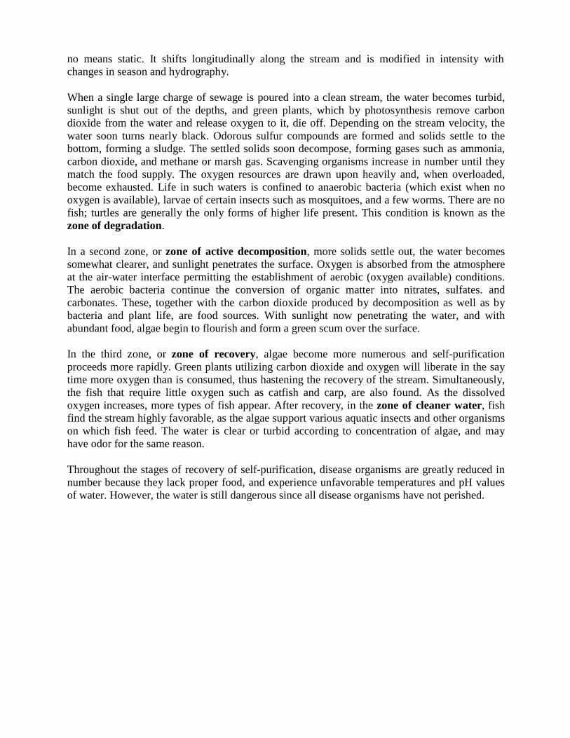
no means static. It shifts longitudinally along the stream and is modified in intensity with
changes in season and hydrography.
When a single large charge of sewage is poured into a clean stream, the water becomes turbid,
sunlight is shut out of the depths, and green plants, which by photosynthesis remove carbon
dioxide from the water and release oxygen to it, die off. Depending on the stream velocity, the
water soon turns nearly black. Odorous sulfur compounds are formed and solids settle to the
bottom, forming a sludge. The settled solids soon decompose, forming gases such as ammonia,
carbon dioxide, and methane or marsh gas. Scavenging organisms increase in number until they
match the food supply. The oxygen resources are drawn upon heavily and, when overloaded,
become exhausted. Life in such waters is confined to anaerobic bacteria (which exist when no
oxygen is available), larvae of certain insects such as mosquitoes, and a few worms. There are no
fish; turtles are generally the only forms of higher life present. This condition is known as the
zone of degradation.
In a second zone, or zone of active decomposition, more solids settle out, the water becomes
somewhat clearer, and sunlight penetrates the surface. Oxygen is absorbed from the atmosphere
at the air-water interface permitting the establishment of aerobic (oxygen available) conditions.
The aerobic bacteria continue the conversion of organic matter into nitrates, sulfates. and
carbonates. These, together with the carbon dioxide produced by decomposition as well as by
bacteria and plant life, are food sources. With sunlight now penetrating the water, and with
abundant food, algae begin to flourish and form a green scum over the surface.
In the third zone, or zone of recovery, algae become more numerous and self-purification
proceeds more rapidly. Green plants utilizing carbon dioxide and oxygen will liberate in the say
time more oxygen than is consumed, thus hastening the recovery of the stream. Simultaneously,
the fish that require little oxygen such as catfish and carp, are also found. As the dissolved
oxygen increases, more types of fish appear. After recovery, in the zone of cleaner water, fish
find the stream highly favorable, as the algae support various aquatic insects and other organisms
on which fish feed. The water is clear or turbid according to concentration of algae, and may
have odor for the same reason.
Throughout the stages of recovery of self-purification, disease organisms are greatly reduced in
number because they lack proper food, and experience unfavorable temperatures and pH values
of water. However, the water is still dangerous since all disease organisms have not perished.
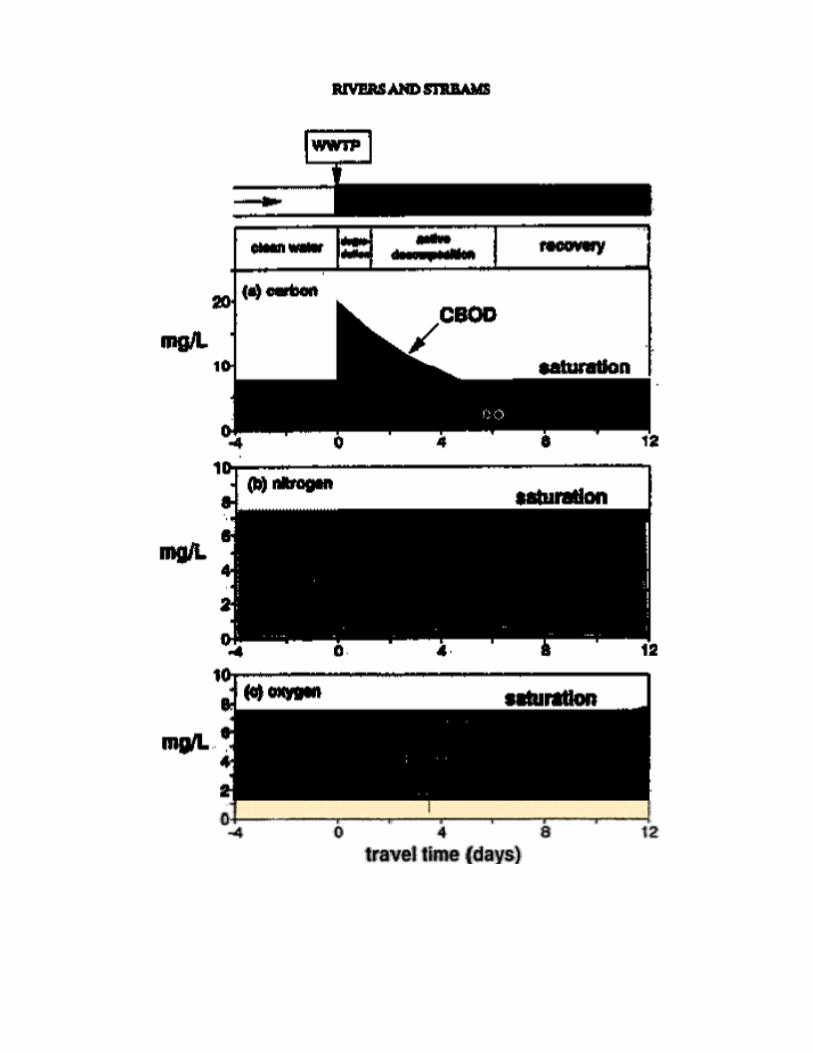
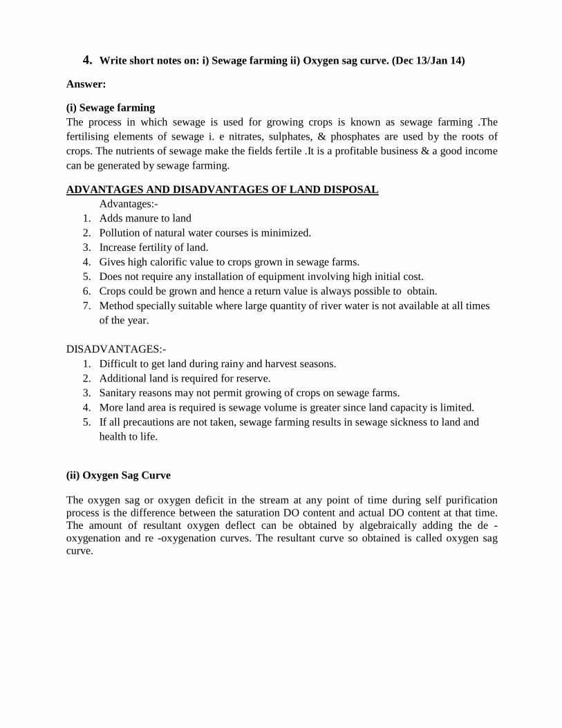
4. Write short notes on: i) Sewage farming ii) Oxygen sag curve. (Dec 13/Jan 14)
Answer:
(i) Sewage farming
The process in which sewage is used for growing crops is known as sewage farming .The
fertilising elements of sewage i. e nitrates, sulphates, & phosphates are used by the roots of
crops. The nutrients of sewage make the fields fertile .It is a profitable business & a good income
can be generated by sewage farming.
ADVANTAGES AND DISADVANTAGES OF LAND DISPOSAL
Advantages:-
1. Adds manure to land
2. Pollution of natural water courses is minimized.
3. Increase fertility of land.
4. Gives high calorific value to crops grown in sewage farms.
5. Does not require any installation of equipment involving high initial cost.
6. Crops could be grown and hence a return value is always possible to obtain.
7. Method specially suitable where large quantity of river water is not available at all times
of the year.
DISADVANTAGES:-
1. Difficult to get land during rainy and harvest seasons.
2. Additional land is required for reserve.
3. Sanitary reasons may not permit growing of crops on sewage farms.
4. More land area is required is sewage volume is greater since land capacity is limited.
5. If all precautions are not taken, sewage farming results in sewage sickness to land and
health to life.
(ii) Oxygen Sag Curve
The oxygen sag or oxygen deficit in the stream at any point of time during self purification
process is the difference between the saturation DO content and actual DO content at that time.
The amount of resultant oxygen deflect can be obtained by algebraically adding the de -
oxygenation and re -oxygenation curves. The resultant curve so obtained is called oxygen sag
curve.
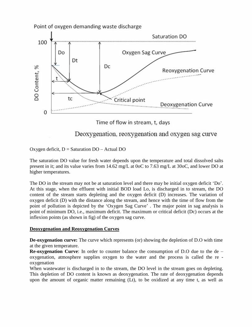
Oxygen deficit, D = Saturation DO – Actual DO
The saturation DO value for fresh water depends upon the temperature and total dissolved salts
present in it; and its value varies from 14.62 mg/L at 0oC to 7.63 mg/L at 30oC, and lower DO at
higher temperatures.
The DO in the stream may not be at saturation level and there may be initial oxygen deficit „Do‟.
At this stage, when the effluent with initial BOD load Lo, is discharged in to stream, the DO
content of the stream starts depleting and the oxygen deficit (D) increases. The variation of
oxygen deficit (D) with the distance along the stream, and hence with the time of flow from the
point of pollution is depicted by the „Oxygen Sag Curve‟ . The major point in sag analysis is
point of minimum DO, i.e., maximum deficit. The maximum or critical deficit (Dc) occurs at the
inflexion points (as shown in fig) of the oxygen sag curve.
Deoxygenation and Reoxygenation Curves
De-oxygenation curve: The curve which represents (or) showing the depletion of D.O with time
at the given temperature.
Re-oxygenation Curve: In order to counter balance the consumption of D.O due to the de –
oxygenation, atmosphere supplies oxygen to the water and the process is called the re -
oxygenation
When wastewater is discharged in to the stream, the DO level in the stream goes on depleting.
This depletion of DO content is known as deoxygenation. The rate of deoxygenation depends
upon the amount of organic matter remaining (Lt), to be oxidized at any time t, as well as
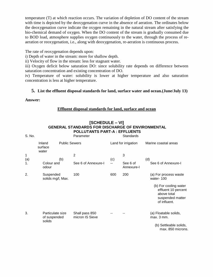
temperature (T) at which reaction occurs. The variation of depletion of DO content of the stream
with time is depicted by the deoxygenation curve in the absence of aeration. The ordinates below
the deoxygenation curve indicate the oxygen remaining in the natural stream after satisfying the
bio-chemical demand of oxygen. When the DO content of the stream is gradually consumed due
to BOD load, atmosphere supplies oxygen continuously to the water, through the process of re-
aeration or reoxygenation, i.e., along with deoxygenation, re-aeration is continuous process.
The rate of reoxygenation depends upon:
i) Depth of water in the stream: more for shallow depth.
ii) Velocity of flow in the stream: less for stagnant water.
iii) Oxygen deficit below saturation DO: since solubility rate depends on difference between
saturation concentration and existing concentration of DO.
iv) Temperature of water: solubility is lower at higher temperature and also saturation
concentration is less at higher temperature.
5. List the effluent disposal standards for land, surface water and ocean.(June/July 13)
Answer:
Effluent disposal standards for land, surface and ocean
[SCHEDULE – VI] GENERAL STANDARDS FOR DISCHARGE OF ENVIRONMENTAL
POLLUTANTS PART-A : EFFLUENTS S. No. Parameter Standards
Inland Public Sewers surface water
1 2 (a) (b) 1. Colour and See 6 of Annexure-I
odour
Land for irrigation
3 (c) -- See 6 of
Annexure-I
Marine coastal areas (d)
See 6 of Annexure-I
2. Suspended solids mg/l, Max.
3. Particulate size of suspended solids
100 600 200
Shall pass 850 -- --micron IS Sieve
(a) For process waste water- 100
(b) For cooling water effluent 10 percent above total suspended matter of influent.
(a) Floatable solids, max. 3 mm.
(b) Settleable solids, max. 850 microns.
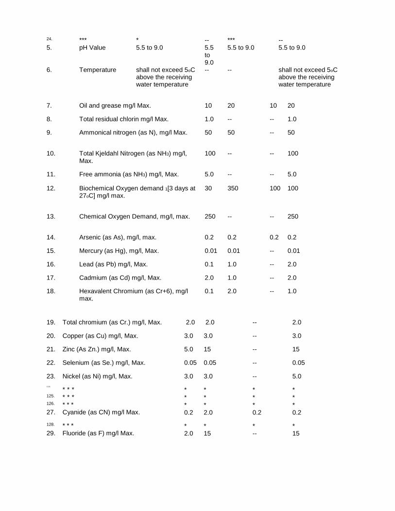
24. ***
5. pH Value 6. Temperature
* --5.5 to 9.0 5.5
to 9.0
shall not exceed 5oC --above the receiving water temperature
***
5.5 to 9.0 --
--
5.5 to 9.0 shall not exceed 5oC above the receiving water temperature
7. Oil and grease mg/l Max. 10 20 10 20
8. Total residual chlorin mg/l Max. 1.0 -- -- 1.0
9. Ammonical nitrogen (as N), mg/l Max. 50 50 -- 50
10. Total Kjeldahl Nitrogen (as NH3) mg/l, 100 -- -- 100 Max.
11. Free ammonia (as NH3) mg/l, Max. 5.0 -- -- 5.0 12. Biochemical Oxygen demand 1[3 days at 30 350 100 100
27oC] mg/l max.
13. Chemical Oxygen Demand, mg/l, max. 250 -- -- 250
14. Arsenic (as As), mg/l, max. 0.2 0.2 0.2 0.2
15. Mercury (as Hg), mg/l, Max. 0.01 0.01 -- 0.01
16. Lead (as Pb) mg/l, Max. 0.1 1.0 -- 2.0
17. Cadmium (as Cd) mg/l, Max. 2.0 1.0 -- 2.0
18. Hexavalent Chromium (as Cr+6), mg/l 0.1 2.0 -- 1.0 max.
19. Total chromium (as Cr.) mg/l, Max.
20. Copper (as Cu) mg/l, Max.
21. Zinc (As Zn.) mg/l, Max.
22. Selenium (as Se.) mg/l, Max.
23. Nickel (as Ni) mg/l, Max. 1124.
* * * 125. * * * 126. * * * 27. Cyanide (as CN) mg/l Max. 128. * * * 29. Fluoride (as F) mg/l Max.
2.0 2.0 -- 2.0
3.0 3.0 -- 3.0
5.0 15 -- 15
0.05 0.05 -- 0.05
3.0 3.0 -- 5.0
* * * *
* * * *
* * * * 0.2 2.0 0.2 0.2
* * * * 2.0 15 -- 15
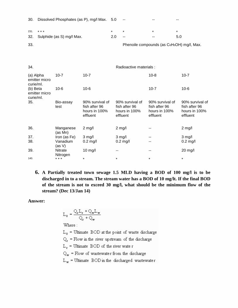
30. Dissolved Phosphates (as P), mg/l Max. 5.0 -- -- -- 231. * * * * * * *
32. Sulphide (as S) mg/l Max. 2.0 -- -- 5.0
33. Phenoile compounds (as C6H5OH) mg/l, Max. 34. Radioactive materials :
(a) Alpha emitter micro curie/ml. (b) Beta emitter micro curie/ml. 35.
36. 37. 38. 39. 140.
10-7 10-6
Bio-assay test
Manganese (as Mn) Iron (as Fe) Vanadium (as V) Nitrate Nitrogen * * *
10-7 10-6
90% survival of fish after 96 hours in 100% effluent
2 mg/l 3 mg/l 0.2 mg/l 10 mg/l *
90% survival of fish after 96 hours in 100% effluent
2 mg/l 3 mg/l 0.2 mg/l -- *
10-8 10-7
90% survival of fish after 96 hours in 100% effluent
-- ---- -- *
10-7 10-6
90% survival of fish after 96 hours in 100% effluent
2 mg/l 3 mg/l 0.2 mg/l 20 mg/l *
6. A Partially treated town sewage 1.5 MLD having a BOD of 100 mg/l is to be
discharged in to a stream. The stream water has a BOD of 10 mg/lt. If the final BOD
of the stream is not to exceed 30 mg/l, what should be the minimum flow of the
stream? (Dec 13/Jan 14)
Answer:
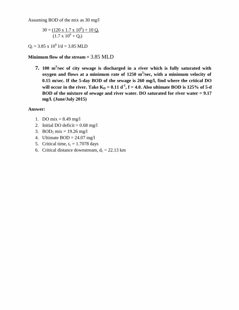
Assuming BOD of the mix as 30 mg/l
30 = (120 x 1.7 x 106) + 10 Qr
(1.7 x 10⁶
+ Qr)
Qr = 3.85 x 10⁶
l/d = 3.85 MLD
Minimum flow of the stream = 3.85 MLD
7. 100 m3/sec of city sewage is discharged in a river which is fully saturated with
oxygen and flows at a minimum rate of 1250 m3/sec, with a minimum velocity of
0.15 m/sec. If the 5-day BOD of the sewage is 260 mg/l, find where the critical DO
will occur in the river. Take KD = 0.11 d-1
, f = 4.0. Also ultimate BOD is 125% of 5-d
BOD of the mixture of sewage and river water. DO saturated for river water = 9.17
mg/l. (June/July 2015)
Answer:
1. DO mix = 8.49 mg/l
2. Initial DO deficit = 0.68 mg/l
3. BOD5 mix = 19.26 mg/l
4. Ultimate BOD = 24.07 mg/l
5. Critical time, tc = 1.7078 days
6. Critical distance downstream, dc = 22.13 km
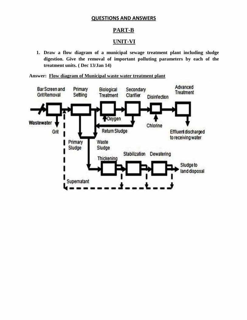
QUESTIONS AND ANSWERS
PART-B
UNIT-VI
1. Draw a flow diagram of a municipal sewage treatment plant including sludge
digestion. Give the removal of important polluting parameters by each of the
treatment units. ( Dec 13/Jan 14)
Answer: Flow diagram of Municipal waste water treatment plant
Preliminary treatment
The objective of preliminary treatment is the removal of coarse solids and other large materials
often found in raw wastewater. Removal of these materials is necessary to enhance the operation
and maintenance of subsequent treatment units. Preliminary treatment operations typically
include coarse screening, grit removal and, in some cases, comminution of large objects. In grit
chambers, the velocity of the water through the chamber is maintained sufficiently high, or air is
used, so as to prevent the settling of most organic solids. Grit removal is not included as a
preliminary treatment step in most small wastewater treatment plants. Comminutors are
sometimes adopted to supplement coarse screening and serve to reduce the size of large particles
so that they will be removed in the form of a sludge in subsequent treatment processes. Flow
measurement devices, often standing-wave flumes, are always included at the preliminary
treatment stage.
Primary treatment
The objective of primary treatment is the removal of settleable organic and inorganic solids by sedimentation, and the removal of materials that will float (scum) by skimming. Approximately 25 to 50% of the incoming biochemical oxygen demand (BOD5), 50 to 70% of the total
suspended solids (SS), and 65% of the oil and grease are removed during primary treatment. Some organic nitrogen, organic phosphorus, and heavy metals associated with solids are also
removed during primary sedimentation but colloidal and dissolved constituents are not affected.
The effluent from primary sedimentation units is referred to as primary effluent.
In many industrialized countries, primary treatment is the minimum level of pre application
treatment required for wastewater irrigation. It may be considered sufficient treatment if the
wastewater is used to irrigate crops that are not consumed by humans or to irrigate orchards,
vineyards, and some processed food crops. However, to prevent potential nuisance conditions in
storage or flow-equalizing reservoirs, some form of secondary treatment is normally required in
these countries, even in the case of non-food crop irrigation. It may be possible to use at least a
portion of primary effluent for irrigation if off-line storage is provided.
Primary sedimentation tanks or clarifiers may be round or rectangular basins, typically 3 to 5 m
deep, with hydraulic retention time between 2 and 3 hours. Settled solids (primary sludge) are
normally removed from the bottom of tanks by sludge rakes that scrape the sludge to a central
well from which it is pumped to sludge processing units. Scum is swept across the tank surface
by water jets or mechanical means from which it is also pumped to sludge processing units.
In large sewage treatment plants (> 7600 m3/d in the US), primary sludge is most commonly
processed biologically by anaerobic digestion. In the digestion process, anaerobic and facultative
bacteria metabolize the organic material in sludge (see Example 3), thereby reducing the volume
requiring ultimate disposal, making the sludge stable (non-putrescible) and improving its
dewatering characteristics. Digestion is carried out in covered tanks (anaerobic digesters),
typically 7 to 14 m deep. The residence time in a digester may vary from a minimum of about 10
days for high-rate digesters (well-mixed and heated) to 60 days or more in standard-rate
digesters. Gas containing about 60 to 65% methane is produced during digestion and can be
recovered as an energy source. In small sewage treatment plants, sludge is processed in a variety
of ways including: aerobic digestion, storage in sludge lagoons, direct application to sludge
drying beds, in-process storage (as in stabilization ponds), and land application.
Secondary treatment
The objective of secondary treatment is the further treatment of the effluent from primary treatment to remove the residual organics and suspended solids. In most cases, secondary
treatment follows primary treatment and involves the removal of biodegradable dissolved and
colloidal organic matter using aerobic biological treatment processes. Aerobic biological treatment (see Box) is performed in the presence of oxygen by aerobic microorganisms
(principally bacteria) that metabolize the organic matter in the wastewater, thereby producing more microorganisms and inorganic end-products (principally CO2, NH3, and H2O). Several
aerobic biological processes are used for secondary treatment differing primarily in the manner
in which oxygen is supplied to the microorganisms and in the rate at which organisms metabolize the organic matter.
High-rate biological processes are characterized by relatively small reactor volumes and high
concentrations of microorganisms compared with low rate processes. Consequently, the growth
rate of new organisms is much greater in high-rate systems because of the well controlled
environment. The microorganisms must be separated from the treated wastewater by
sedimentation to produce clarified secondary effluent. The sedimentation tanks used in
secondary treatment, often referred to as secondary clarifiers, operate in the same basic manner
as the primary clarifiers described previously. The biological solids removed during secondary
sedimentation, called secondary or biological sludge, are normally combined with primary
sludge for sludge processing.
Common high-rate processes include the activated sludge processes, trickling filters or bio-
filters, oxidation ditches, and rotating biological contactors (RBC). A combination of two of
these processes in series (e.g., bio-filter followed by activated sludge) is sometimes used to treat
municipal wastewater containing a high concentration of organic material from industrial
sources.
2. Explain the importance of providing racks and screens in a waste-water treatment
plant. Draw a neat sketch of a bar screen and explain the loss of head through the
screen. (June/July 2015)
Answer:
The first unit operation generally encountered in wastewater treatment plants is screening. A
screen is a device with openings, generally of uniform size, that is used to retain solids found in
the influent wastewater to the treatment plant. The principal role of screening is to remove coarse
materials from the flow stream that could:
1. Damage subsequent process equipment.
2. Reduce overall treatment process reliability & effectiveness, or
3. Contaminate waste way
There are two types of screening processes
1. Manually Operated
2. Automatically
1. Course screens (Bar Racks)
2. Fine screens
3. Micro screens.
Coarse Screens
Micro Screening
Fine Screens
6 to 150mm
< 0.5 k
less then 6mm
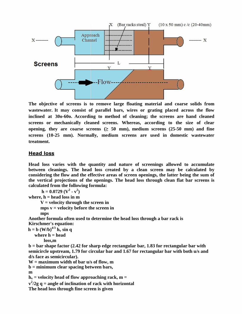
The objective of screens is to remove large floating material and coarse solids from
wastewater. It may consist of parallel bars, wires or grating placed across the flow
inclined at 30o-60o. According to method of cleaning; the screens are hand cleaned
screens or mechanically cleaned screens. Whereas, according to the size of clear
opening, they are coarse screens (≥ 50 mm), medium screens (25-50 mm) and fine
screens (10-25 mm). Normally, medium screens are used in domestic wastewater
treatment.
Head loss
Head loss varies with the quantity and nature of screenings allowed to accumulate between cleanings. The head loss created by a clean screen may be calculated by considering the flow and the effective areas of screen openings, the latter being the sum of the vertical projections of the openings. The head loss through clean flat bar screens is calculated from the following formula:
h = 0.0729 (V2
- v2)
where, h = head loss in m
V = velocity through the screen in
mps v = velocity before the screen in
mps Another formula often used to determine the head loss through a bar rack is Kirschmer's equation:
h = b (W/b)4/3
hv sin q
where h = head loss,m
b = bar shape factor (2.42 for sharp edge rectangular bar, 1.83 for rectangular bar with
semicircle upstream, 1.79 for circular bar and 1.67 for rectangular bar with both u/s and
d/s face as semicircular). W = maximum width of bar u/s of flow, m b = minimum clear spacing between bars, m hv = velocity head of flow approaching rack, m =
v2/2g q = angle of inclination of rack with horizontal
The head loss through fine screen is given

by h = (1/2g) (Q/CA) where, h = head loss, m
Q = discharge, m3/s
C = coefficient of discharge (typical value 0.6)
A = effective submerged open area, m2
The quantity of screenings depends on the nature of the wastewater and the screen openings.
3. Explain the functioning of screens and Grit chamber in the treatment of municipal
wastewater. (June/July 14, June/July 2015)
Answer:
The removal of solids from the incoming wastewater flow is accomplished in steps. The first
steps involve physical separation of the solids by screening and by gravity. The larger solids can
be removed using screens and the heavy solids can be removed using settling processes. The
dissolved organic material (and some of the lighter suspended solids) will remain in the sewage
flow after primary clarification. The first step in the solids removal process is screening to
remove the larger solids and "rags." After screening, a grit removal process is used to separate
the heavier inorganic solids like sand and inert organics like coffee grounds from the flow. Rags
can clog piping and pumps in downstream processes. Grit can also cause clogging problems and
can damage pumps. Grit that isn't removed in the grit chamber will end up in the solids handling
system where it will eventually collect in the digesters. This will reduce available digester
capacity. These processes that remove inorganic solids are collectively referred to as
pretreatment.
SCREENS
Bigger pieces of wood, plastic, metal, rubber, textile and other waste materials out of wastewater
is being removed by using bar screens.
A bar screen consists of a series parallel of steel bars that are placed vertically in the influent
flow channel. The bars are usually spaced about 1/2-3/4 inches apart. In some cases, two sets of
screens are placed in the channel the upstream screen may have bars spaced 2-3 inches apart and
the downstream screen will have the normal spacing. The front screen is sometimes referred to as
a "trash screen." It is designed to catch large chunks of debris to avoid overloading the smaller
screen. As the screen gets clogged with rags the water level upstream will rise. If the screen isn't
cleaned regularly the upstream water level can back up and flood the structure.
Two types of bar screens:
1. Coarse sieve (rake) and
2. Fine sieve.
Coarse sieves have openings equal to or greater than 6 mm and generally protective role, while
using a fine sieve, with openings smaller than 6 mm, and can achieve significant removal of
suspended solids from the wastewater.
The grid is usually made up of parallel rods, while the fine screen usually used wire cloth or
perforated metal plate.
Grit Chambers
Grit chambers are basin to remove the inorganic particles to prevent damage to the pumps, and to
prevent their accumulation in sludge digestors.
A portion of the suspended solids load of municipal waste water consists of grit material. If not
removed in preliminary treatment, grit in primary settling tank can cause abnormal abrasive wear
on mechanical equipment and sludge pumps, can clog by deposition, and can accumulate in
sludge holding tanks and digesters. Therefore grit removal is necessary to protect the moving
mechanical equipments and pump elements from abrasion and accompanying wear and tear.
Removal of grit also reduces the frequency of cleaning of digesters and settling tanks.
Grit removal devices rely upon the difference in specific gravity between organic and inorganic
solids to effect their separation.
Composition of grit
Grit in sewage consists of coarse particles of sand, ash and clinkers, egg shells, bone chips and
many inert materials inorganic in nature. Both the quantity and quality of grit varies depending
upon
a) Types of street surfaces encountered
b) Relative areas served
c) Climatic conditions
d) Types of inlet and catch basins
e) Amount of storm water diverted
f) Sewer grades
g) Ground water characteristics, etc.,
h) Social habits
The specific gravity of grit is usually in the range of 2.4 to 2.65. Grit is non putrescible in nature
and higher hydraulic subsidence than organic solids. Hence it is possible to separate the gritty
material from organic solids by differential sedimentation in a grit chamber.
Types of grit chambers Grit chambers are of two types, mechanically cleaned and manually cleaned. The choice depends
on several factors such as the quantity and quality of grit to be handled, head loss requirements,
space requirements etc.,
Mechanically cleaned grit chambers are provided with mechanical equipment for collection,
elevation and washing of grit which are operated either on a continuous or intermittent basis.
Manually cleaned grit chambers should have sufficient capacity for storage of grit between the
intervals of cleansing. Atleast two tanks must be there, so that when one is under cleaning
operation the other must be working. These tanks must be cleaned atleast once in every week.
The simplest method of removal is by means of shovel and wheel barriers.
4. What are skimming tanks? Explain with a neat sketch. (June/July 2015) Answer:
A skimming tank is a chamber so arranged that the floating matter like oil, fat, grease etc., rise
and remain on the surface of the waste water (Sewage) until removed, while the liquid flows out
continuously under partitions or baffles.
It is necessary to remove the floating matter from sewage otherwise it may ap pear in the form of
unsightly scum on the surface of the settling tanks or inter fere with the activated sludge process
of sewage treatment. It is mostly present in the industrial sewage. In ordinary sanitary sewage, its
amount is usually too small.
The chamber is a long trough shaped structure divided up into two or three lateral compartments
by vertical baffle walls having slots for a short distance below the sewage surface and permitting
oil and grease to escape into stilling compartments.
The rise of floating matter is brought about the blowing air into the sewage from diffusers placed
in the bottom. Sewage enters the tank from one end, flows longitudinally and leaves out through
a narrow inclined duct. A theoretical detention period of 3 minutes is enough. The floating
matter can be either hand or mechanically removed.
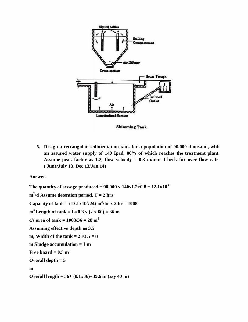
5. Design a rectangular sedimentation tank for a population of 90,000 thousand, with
an assured water supply of 140 Ipcd, 80% of which reaches the treatment plant.
Assume peak factor as 1.2, flow velocity = 0.3 m/min. Check for over flow rate.
( June/July 13, Dec 13/Jan 14)
Answer:
The quantity of sewage produced = 90,000 x 140x1.2x0.8 = 12.1x10³
m3/d Assume detention period, T = 2 hrs
Capacity of tank = (12.1x10³/24) m
3/hr x 2 hr = 1008
m3
Length of tank = L=0.3 x (2 x 60) = 36 m
c/s area of tank = 1008/36 = 28 m3
Assuming effective depth as 3.5
m, Width of the tank = 28/3.5 = 8
m Sludge accumulation = 1 m
Free board = 0.5 m
Overall depth = 5
m
Overall length = 36+ (0.1x36)=39.6 m (say 40 m)
Check for over flow rate
SOR = Flow/ surface area
= 12100 m3/d/(40 x 8) m
2
SOR = 37.8 m3/m
2/d ( safe)
6. Calculate the diameter, depth and weir loading of a primary sedimentation tank,
using the following data: Sewage flow - 6 MLD Detention period - 2 hrs
Overflow rate. - 1500 Its/m2/hr. (June/July13)
Answer: Capacity, C = Discharge x Detention time
= (6x10³/24) m
3/hr x 2 hr
= 500 m3
Surface overflow rate = Flow/ surface area = (6x10⁶/24) l/hr
A
1500 lts/m2/hr = (6x10
6/24) l/hr
A
Surface area, A = 166.67 m2
Diameter, D = 14.57 m
Depth = Capacity/Area = 500/166.67 = 3 m
Weir loading, WL = Flow/weir length = Q/πD
=6 x 10³
m3/d/(3.14 x 14.57)m = 131.15 m
3/m/d
7. Design a grit chamber for a town having a population of 1 lakh. Assume suitable
data necessary. (June/July 14)
Answer:
Assuming per capita sewage production as 120 litres/day
Average daily flow = 1, 00,000 X 120 litres
12X106
1000X24X60X60
= 0.139 m3/sec
Maximum flow = 3X 0.139 = 0.417 m3/sec
Assuming a horizontal velocity of 30 cm/sec, and detention time as 60 seconds,
=
Cross section area of the tank = A = VELOCITY
= 0
0.3
7 = 1.39 m
2
Length of the tank required = L = horizontal velocity of flow X detention time
= 0.3 X 60 = 18 m.
There fore capacity of the tank = c/s area X length = 1.39 X 18
V = 25 m3
Quantity of grit at the rate of 25 litres/million litres/day = 120X105X25
= 300litres/day
Assuming cleaning of grit chamber is once in a week,
Storage for one week = 7 X 300 = 2100 litres = 2.1 m3
Total tank capacity = 25 + 2.1 = 27.1 m3
Assuming the size of the particles as 0.2 mm and sp.gr 2.65, and temperature as 20Oc,
Settling velocity given by Hazen formula,
VS = d (3T + 70) = 0.02 (3 X 20 + 70) = 2.2 cm/sec.
Therefore depth of the tank required = settling velocity X detention time = 2.2 X 60 = 132 cm
Liquid depth = 1.32m
Breadth = 1.32m
= 1.05 m
Provide 0.27 m free board.
Total depth of tank = 1.32 + 0.27 + 0.11 m sludge depth Depth = 1.7 m; Breadth = 1.05 m; Length = 18 m
Provide two chambers of above dimensions so that when one is in cleaning operation, the
other will be working.
FLOW .41
10 6
1.39m 2
QUESTIONS AND ANSWERS
PART-B
UNIT-VII
1. Explain the biological treatment techniques for treating waste-water. (June/July
2015)
Answer:
Classification of biological treatment processes is often based on the nature of microbial growth.
Organisms can be suspended in wastewater, or they can be attached to an inert surface.
If the micro-organisms are suspended in the Wastewater during biological operation
Suspended growth processes
• Recycling of settled biomass is required.
• While the micro-organisms that are attached to a surface over which they
grow
Attached growth processes
• The biomass attached to media (ex. rock, plastic, wood)
• Recycling of settled biomass is not required.
Suspended Growth Processes: Activated Sludge (most common); (1) Conventional (tapered aeration), (2) Step aeration, (3)
Contact stabilization, (4) Extended aeration, (5) High purity oxygen and (6) Oxidation ditch.
Attached Growth Processes: Attached growth processes can be listed as follows;
(1) Trickling filter (2) Rotating disks and (3) Biological towers.
Lagoons: Lagoons can be listed as follows; (1) Mechanically aerated and (2) Waste stabilization
ponds.
2. What are HRTF’s? Explain importance of recirculation and its effect on the
efficiency of HRTF’s. (June/July 2015)
Answer:
The High Rate Trickling Filters (HRTF), have the same construction details, but the
recirculation of effluent is provided.. Part of the settled treated effluent is pumped to the PST or
to the filter. Recirculation of effluent is an essential and important feature of the HRTF. Thus the
incoming wastewater is diluted and TSS concentrations are reduced.
High-rate filters are usually characterized by higher hydraulic and organic loadings than low-rate
filters. The higher BOD loading is accomplished by applying a larger volume of waste per unit
surface area of the filter.
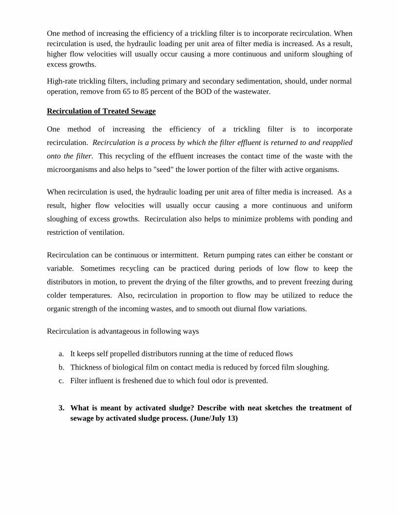
One method of increasing the efficiency of a trickling filter is to incorporate recirculation. When
recirculation is used, the hydraulic loading per unit area of filter media is increased. As a result,
higher flow velocities will usually occur causing a more continuous and uniform sloughing of
excess growths.
High-rate trickling filters, including primary and secondary sedimentation, should, under normal
operation, remove from 65 to 85 percent of the BOD of the wastewater.
Recirculation of Treated Sewage
One method of increasing the efficiency of a trickling filter is to incorporate
recirculation. Recirculation is a process by which the filter effluent is returned to and reapplied
onto the filter. This recycling of the effluent increases the contact time of the waste with the
microorganisms and also helps to "seed" the lower portion of the filter with active organisms.
When recirculation is used, the hydraulic loading per unit area of filter media is increased. As a
result, higher flow velocities will usually occur causing a more continuous and uniform
sloughing of excess growths. Recirculation also helps to minimize problems with ponding and
restriction of ventilation.
Recirculation can be continuous or intermittent. Return pumping rates can either be constant or
variable. Sometimes recycling can be practiced during periods of low flow to keep the
distributors in motion, to prevent the drying of the filter growths, and to prevent freezing during
colder temperatures. Also, recirculation in proportion to flow may be utilized to reduce the
organic strength of the incoming wastes, and to smooth out diurnal flow variations.
Recirculation is advantageous in following ways
a. It keeps self propelled distributors running at the time of reduced flows
b. Thickness of biological film on contact media is reduced by forced film sloughing.
c. Filter influent is freshened due to which foul odor is prevented.
3. What is meant by activated sludge? Describe with neat sketches the treatment of
sewage by activated sludge process. (June/July 13)
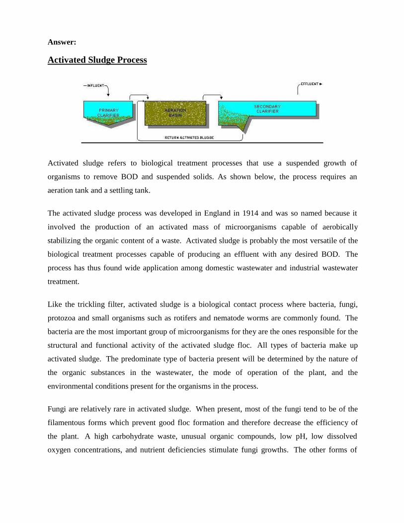
Answer:
Activated Sludge Process
Activated sludge refers to biological treatment processes that use a suspended growth of
organisms to remove BOD and suspended solids. As shown below, the process requires an
aeration tank and a settling tank.
The activated sludge process was developed in England in 1914 and was so named because it
involved the production of an activated mass of microorganisms capable of aerobically
stabilizing the organic content of a waste. Activated sludge is probably the most versatile of the
biological treatment processes capable of producing an effluent with any desired BOD. The
process has thus found wide application among domestic wastewater and industrial wastewater
treatment.
Like the trickling filter, activated sludge is a biological contact process where bacteria, fungi,
protozoa and small organisms such as rotifers and nematode worms are commonly found. The
bacteria are the most important group of microorganisms for they are the ones responsible for the
structural and functional activity of the activated sludge floc. All types of bacteria make up
activated sludge. The predominate type of bacteria present will be determined by the nature of
the organic substances in the wastewater, the mode of operation of the plant, and the
environmental conditions present for the organisms in the process.
Fungi are relatively rare in activated sludge. When present, most of the fungi tend to be of the
filamentous forms which prevent good floc formation and therefore decrease the efficiency of
the plant. A high carbohydrate waste, unusual organic compounds, low pH, low dissolved
oxygen concentrations, and nutrient deficiencies stimulate fungi growths.
The other forms of
microorganisms present in activated sludge play a minor role in the actual stabilization of the
organics in wastewater. In addition, support equipment, including return pumps, waste pumps,
flow measurement devices for return and waste, as well as equipment to provide aeration (mixers
and/or blowers) is also required.
Primary effluent is mixed with return activated sludge to form mixed liquor. The mixed liquor is
aerated for a specified length of time. During the aeration the activated sludge organisms use the
available organic matter as food producing stable solids and more organisms. The suspended
solids produced by the process and the additional organisms become part of the activated sludge.
The solids are then separated from the wastewater in the settling tank. The solids are returned to
the influent of the aeration tank (return activated sludge). Periodically the excess solids and
organisms are removed from the system (waste activated sludge). Failure to remove waste solids
will result in poor performance and loss of solids out of the system over the settling tank effluent
weir.
4. Explain with a neat sketch, the working of trickling filter.(June/July 13, Dec13/Jan
14)
Answer:
Trickling filter is an attached growth process i.e. process in which microorganisms responsible
for treatment are attached to an inert packing material. Packing material used in attached growth
processes include rock, gravel, slag, sand, redwood, and a wide range of plastic and other
synthetic materials.
A trickling filter consists of a bed of highly permeable media on whose surface a mixed
population of microorganisms is developed as a slime layer. An attached growth process is
happening in a trickling filter. Passage of wastewater through the filter causes the development
of a gelatinous coating of bacteria, protozoa and other organisms on the media. With time, the
thickness of the slime layer increases preventing oxygen from penetrating the full depth of the
slime layer. In the absence of oxygen, anaerobic decomposition becomes active near the surface
of the media.
The trickling filter consists of several major components including distribution system, media,
under drains, effluent channel, secondary settling tank, and recirculation pumps and piping. Each
of these components has one or more purposes.
The construction of a trickling filter consists of a cylindrical structure made of concrete or brick,
an inside honey combed wall and the filter media which consists of gravel of size 25 mm to
75mm. the depth of the filtering media may vary from 2 to 3m.The under drainage consists of
vitrified clay blocks with adequate openings. It is usually laid at a slope of 1 in 300, so as to
maintain the velocity of flow of effluent as 0.9 m/sec. the influent to the trickling filter enters the
tank trough a dosing tank kept at a height to transport the sewage by gravity. It enters the
trickling filter through a central column inside the filter and reaches the rotating arms which has
openings or spray nozzles through which the influent is sprayed or trickled to the bed. The
rotating arm rotates at a speed of 2rpm. The media and the arms are separated by a distance of
minimum, 15 to 20 cm to ensure good air circulation, it also get a good air flow through the
honey combed wall and the under drainage system.
In operation, wastewater is distributed evenly over the surface of the trickling filter media. As
the wastewater flows over the surface of the media the organisms in the slime remove the
organic matter from the flow.
Step by Step Process Description of Trickling Filter
The wastewater in trickling filter is distributed over the top area of a vessel containing
non-submerged packing material.
Air circulation in the void space, by either natural draft or blowers, provides oxygen for
the microorganisms growing as an attached biofilm.
During operation, the organic material present in the wastewater is metabolised by the
biomass attached to the medium. The biological slime grows in thickness as the organic
matter abstracted from the flowing wastewater is synthesized into new cellular material.
The thickness of the aerobic layer is limited by the depth of penetration of oxygen into
the microbial layer.
The micro-organisms near the medium face enter the endogenous phase as the substrate
is metabolised before it can reach the micro-organisms near the medium face as a result
of increased thickness of the slime layer and loose their ability to cling to the media
surface. The liquid then washes the slime off the medium and a new slime layer starts to
grow. This phenomenon of losing the slime layer is called sloughing.
The sloughed off film and treated wastewater are collected by an under drainage which
also allows circulation of air through filter. The collected liquid is passed to a settling
tank used for solid- liquid separation.
5. Differentiate between the following terms:
i) Sludge volume index and bulking of sludge
ii) Suspended and attached growth process. (June/July14)
Answer:
i) Sludge volume index and bulking of sludge
Sludge Volume Index
Sludge volume index is a quality indicator. It reflects the settling quality of the sludge. As the
SVI increases, the sludge settles slower, does not compact as well, and is likely to result in more
effluent suspended solids.
Sample problem :
The sample used in the previous example (SSV) has an MLSS concentration of 2,800 mg/L.
What is the SVI?
Bulking of Sludge
Bulking can be said to have occurred in activated sludge plants when the sludge does not settle
easily and has an excessive volume. This can lead to carry over from the final effluent clarifies.
A bulking sludge is usually characterised by a sedimentation rate of less than 0.3 m/h, an SSVI
or SVI of above 120 and 180 ml/g respectively and a low density structure.
The cause of bulking is normally due to either excessive filamentous growth or micro-organisms
producing extracellular such as polysaccharide.
There are a number of short-term control measures which include biocide addition, use of
flocculating chemicals or increasing the RAS flow. These measures generally treat the symptoms
and not the underlying cause of the problem. The production of extracellular material and
excessive filamentous micro-organisms have been related to nutrient deficiency, low dissolved
oxygen and configuration of the aeration basin. This article deals with the control of activated
sludge bulking based on these causes.
ii) Suspended and attached growth process.
Organisms can be suspended in wastewater, or they can be attached to an inert surface.
If the micro-organisms are suspended in the WW during biological operation
Suspended growth processes • Recycling of settled biomass is required.
• While the micro-organisms that are attached to a surface over which they
grow
Attached growth processes • The biomass attached to media (ex. rock, plastic, wood)
• Recycling of settled biomass is not required.
Suspended Growth Processes: Activated Sludge (most common); (1) Conventional (tapered aeration), (2) Step aeration, (3)
Contact stabilization, (4) Extended aeration, (5) High purity oxygen and (6) Oxidation ditch.
Attached Growth Processes: Attached growth processes can be listed as follows;
(1) Trickling filter (2) Rotating disks and (3) Biological towers.
6. Discuss the effect of recirculation in filters with figure. (Dec 13/Jan 14)
Answer:
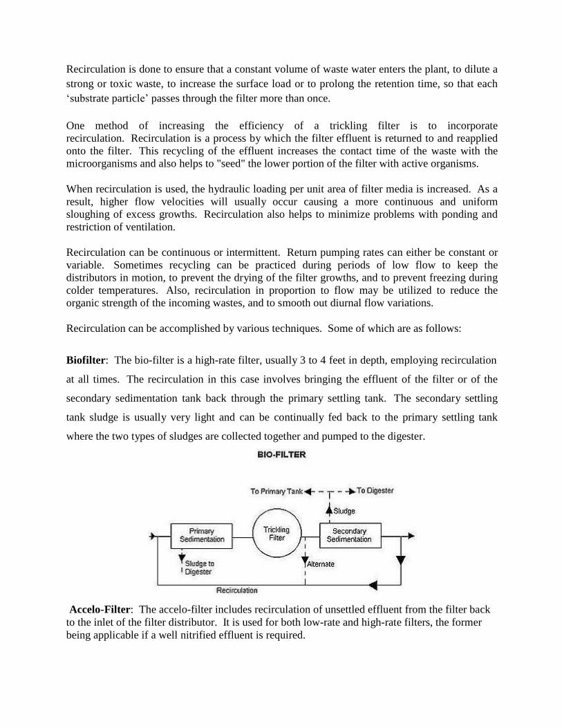
Recirculation is done to ensure that a constant volume of waste water enters the plant, to dilute a
strong or toxic waste, to increase the surface load or to prolong the retention time, so that each
„substrate particle‟ passes through the filter more than once.
One method of increasing the efficiency of a trickling filter is to incorporate
recirculation. Recirculation is a process by which the filter effluent is returned to and reapplied
onto the filter. This recycling of the effluent increases the contact time of the waste with the
microorganisms and also helps to "seed" the lower portion of the filter with active organisms.
When recirculation is used, the hydraulic loading per unit area of filter media is increased. As a
result, higher flow velocities will usually occur causing a more continuous and uniform
sloughing of excess growths. Recirculation also helps to minimize problems with ponding and
restriction of ventilation.
Recirculation can be continuous or intermittent. Return pumping rates can either be constant or
variable. Sometimes recycling can be practiced during periods of low flow to keep the
distributors in motion, to prevent the drying of the filter growths, and to prevent freezing during
colder temperatures. Also, recirculation in proportion to flow may be utilized to reduce the
organic strength of the incoming wastes, and to smooth out diurnal flow variations.
Recirculation can be accomplished by various techniques. Some of which are as follows:
Biofilter: The bio-filter is a high-rate filter, usually 3 to 4 feet in depth, employing recirculation
at all times. The recirculation in this case involves bringing the effluent of the filter or of the
secondary sedimentation tank back through the primary settling tank. The secondary settling
tank sludge is usually very light and can be continually fed back to the primary settling tank
where the two types of sludges are collected together and pumped to the digester.
Accelo-Filter: The accelo-filter includes recirculation of unsettled effluent from the filter back
to the inlet of the filter distributor. It is used for both low-rate and high-rate filters, the former
being applicable if a well nitrified effluent is required.
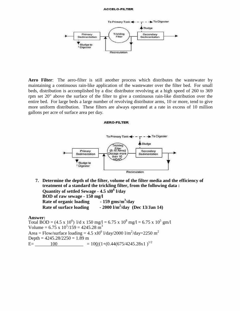
Aero Filter: The aero-filter is still another process which distributes the wastewater by
maintaining a continuous rain-like application of the wastewater over the filter bed. For small
beds, distribution is accomplished by a disc distributor revolving at a high speed of 260 to 369
rpm set 20" above the surface of the filter to give a continuous rain-like distribution over the
entire bed. For large beds a large number of revolving distributor arms, 10 or more, tend to give
more uniform distribution. These filters are always operated at a rate in excess of 10 million
gallons per acre of surface area per day.
7. Determine the depth of the filter, volume of the filter media and the efficiency of treatment of a standard the trickling filter, from the following data :
Quantity of settled Sewage - 4.5 xl06
l/day BOD of raw sewage - 150 mg/l Rate of organic loading - 159 gms/m
3/day
Rate of surface loading - 2000 l/m2/day (Dec 13/Jan 14)
Answer: Total BOD = (4.5 x 10
6) l/d x 150 mg/l = 6.75 x 10
8 mg/l = 6.75 x 10
5 gm/l
Volume = 6.75 x 10⁵/159 = 4245.28 m
3
Area = Flow/surface loading = 4.5 xl06
l/day/2000 l/m2/day=2250 m
2
Depth = 4245.28/2250 = 1.89 m
E= 100 = 100/(1+(0.44(675/4245.28x1 )1/2
1+0.44(F1.BOD/V1.Rf1)1/2
Efficiency = 85.07%
8. An average operating data for conventional activated sludge treatment plant is as follows:
Waste water flow : 35000 m3/sec
Volume of aeration tank : 10000 m3
Effluent BOD : 20 mg/1 Effluent suspended solids : 30 mg/1 Influent BOD : 250 mg/l Mixed liquor suspended solids : 2500 mg/1 Waste sludge suspended solids : 9700 mg/1
Quantity of waste sludge : 220 m3/d
Based on the above information, determine i) Aeration period (hr) ii) Food to microorganism ratio (F/m) (kg BOD per day/kg MLSS) iii) Percentage efficiency of BOD removal iv) Sludge age (days). (Dec 13 /Jan14)
Answer:
i) Aeration period (hr)= 7.47 hr
ii) Food to microorganism ratio (F/m) (kg BOD per day/kg MLSS) = 0.32 kg
BOD/day/kg MLSS
iii) Percentage efficiency of BOD removal = 92%
iv) Sludge age (days) = 8.58 d
9. Design a low rate filter to treat 6.0 Mld of sewage of BOD of 210 mg/l. The final effluent should be 30 mg/l and organic loading rate is 320 g/m
3/d. (June/July14)
Answer:
Assume 30% of BOD load removed in primary sedimentation i.e., = 210 x 0.30 = 63
mg/l.
Remaining BOD = 210 - 63 = 147 mg/l. Percent of BOD removal required = (147-30) x 100/147 = 80%
BOD load applied to the filter = flow x conc. of sewage (kg/d) = 6 x 106
x 147/106
= 882
kg/d
To find out filter volume, using NRC equation E = 100
1+0.44(F1.BOD/V1.Rf1)1/2
80 = 100 Rf = 1, because no circulation.
1+0.44(882/V1)1/2
2
1
V = 2704 m3
Depth of filter = 1.5 m, Fiter area = 2704/1.5 = 1802.66 m2, and Diameter = 48 m < 60 m
Hydraulic loading rate = 6 x 10⁶/10
3 x 1/1802.66 = 3.33m
3/d/m
2 < 4 hence o.k.
Organic loading rate = 882 x 1000 / 2704 = 326.18 g/d/m3
which is approx. equal to 320.
10. The MLSS concentration in an aeration tank is 2000mg/l and the sludge volume
after 30 minutes of settling in a 1000 ml cylinder is 176 ml. calculate:
i. SVI ii. SDI iii. Required return sludge ratio and iv. SS concentration in
the re-circulated sludge. (June/July 2015)
Answer:
i.
SVI = (176 X 1000)/ 2000 = 88 ml/gm
ii. SDI = (100/SVI)= 100/88 = 1.136
iii. Return Sludge Ratio: Qr MLSS
r = ------ = --------------------- Q (106 / SVI) - MLSS
2000 r = ----------------------- = 0.214
( 106
/ 88 ) - 2000
Return Sludge Ratio, r = 21.4 %
iv. SS concentration in the re-circulated sludge= 106/SVI = 10
6/88 = 11,364 mg/l
1
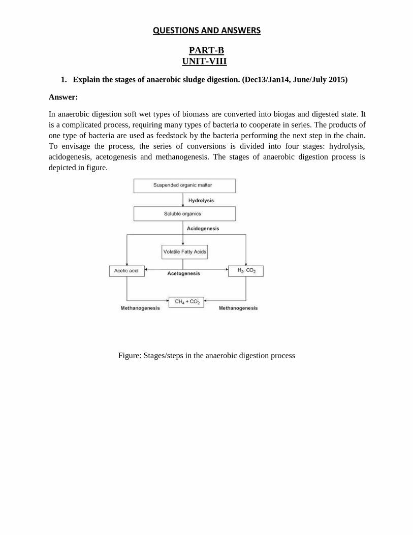
QUESTIONS AND ANSWERS
PART-B
UNIT-VIII
1. Explain the stages of anaerobic sludge digestion. (Dec13/Jan14, June/July 2015) Answer:
In anaerobic digestion soft wet types of biomass are converted into biogas and digested state. It
is a complicated process, requiring many types of bacteria to cooperate in series. The products of
one type of bacteria are used as feedstock by the bacteria performing the next step in the chain.
To envisage the process, the series of conversions is divided into four stages: hydrolysis,
acidogenesis, acetogenesis and methanogenesis. The stages of anaerobic digestion process is
depicted in figure.
Figure: Stages/steps in the anaerobic digestion process
Hydrolysis
The hydrolysis process transforms suspended organic matter into soluble organics. During the
hydrolysis step, polymeric compounds are broken down by extra cellular enzymes into
monomeric or dimeric compounds. The optimal pH for the hydrolysis step is 6, and the
hydrolysis step usually is the rate limiting factor in anaerobic digestion.
A larger surface area enables enzymes to work faster because more enzymes are able to „attack‟
the organic material at the same time. Therefore a method to increase the rate of the hydrolysis is
to increase the surface area of the substrate by previous grinding, boiling etc. Research is
directed to apply this in practice. Also (bio)chemical pre-treatment of the organic material is
being investigated, leading to more accessible polymers and hence to a higher rate and a higher
degree of hydrolysis .
Also a two stage digester is used in practice, enabling the hydrolysis step to proceed under
optimal conditions
Acidogenesis
In the acidogenesis process the soluble organics that were produced by the hydrolysis are
transformed into volatile fatty acids, mostly C2-C4 acids. In essence, glucose (sugar) is
transformed into acids. While hydrolysis is the slowest process, acidogenesis is the quickest
process.
The production of volatile fatty acids lowers the pH in the digester. When the pH drops below 4,
the production of acids stops, it is therefore necessary that the following steps, the acetogenesis
and methanogenesis take place at a sufficient rate. Otherwise the whole process stops, if the
digester has turned acidic.
Acetogenesis
In the acetogenesis process, the volatile fatty acids, (mostly) propionic acid, butyric acid and also
ethanol are combined with water and are transformed into acetic acid, CO2 and H2.
Methanogenesis
In this step the acetic acid, CO2 and H2 are converted into methane. In a stable digestion process
around 70% of the methanogenesis converts acetic acid into CH4 and CO2, and this process is
known as aceticlastic methanogenesis. This is the most efficient converstion from an energetic
standpoint, as it produces the least amount of heat. The remaining 30% of the biogas is produced in
the hydrogenotrophic methanogenesis, and this is the least effective energetic conversion. H2 and CO2
are converted into methane and water
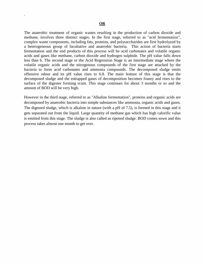
.
OR
The anaerobic treatment of organic wastes resulting in the production of carbon dioxide and
methane, involves three distinct stages. In the first stage, referred to as "acid fermentation",
complex waste components, including fats, proteins, and polysaccharides are first hydrolyzed by
a heterogeneous group of facultative and anaerobic bacteria. This action of bacteria starts
fermentation and the end products of this process will be acid carbonates and volatile organic
acids and gases like methane, carbon dioxide and hydrogen sulphide. The pH value falls down
less than 6. The second stage or the Acid Regression Stage is an intermediate stage where the
volatile organic acids and the nitrogenous compounds of the first stage are attacked by the
bacteria to form acid carbonates and ammonia compounds. The decomposed sludge emits
offensive odour and its pH value rises to 6.8. The main feature of this stage is that the
decomposed sludge and the entrapped gases of decomposition becomes foamy and rises to the
surface of the digester forming scum. This stage continues for about 3 months or so and the
amount of BOD will be very high.
However in the third stage, referred to as "Alkaline fermentation", proteins and organic acids are
decomposed by anaerobic bacteria into simple substances like ammonia, organic acids and gases.
The digested sludge, which is alkaline in nature (with a pH of 7.5), is formed in this stage and it
gets separated out from the liquid. Large quantity of methane gas which has high calorific value
is emitted from this stage. The sludge is also called as ripened sludge. BOD comes sown and this
process takes almost one month to get over.
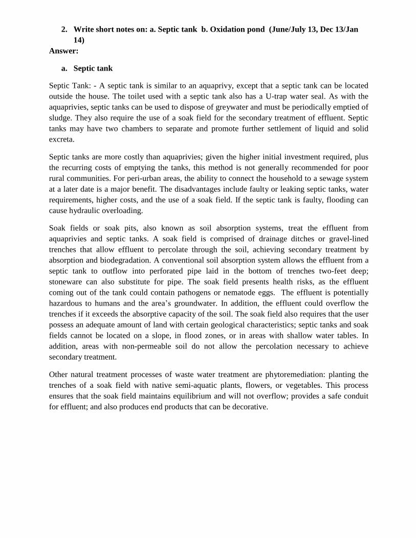
2. Write short notes on: a. Septic tank b. Oxidation pond (June/July 13, Dec 13/Jan
14)
Answer:
a. Septic tank
Septic Tank: - A septic tank is similar to an aquaprivy, except that a septic tank can be located
outside the house. The toilet used with a septic tank also has a U-trap water seal. As with the
aquaprivies, septic tanks can be used to dispose of greywater and must be periodically emptied of
sludge. They also require the use of a soak field for the secondary treatment of effluent. Septic
tanks may have two chambers to separate and promote further settlement of liquid and solid
excreta.
Septic tanks are more costly than aquaprivies; given the higher initial investment required, plus
the recurring costs of emptying the tanks, this method is not generally recommended for poor
rural communities. For peri-urban areas, the ability to connect the household to a sewage system
at a later date is a major benefit. The disadvantages include faulty or leaking septic tanks, water
requirements, higher costs, and the use of a soak field. If the septic tank is faulty, flooding can
cause hydraulic overloading.
Soak fields or soak pits, also known as soil absorption systems, treat the effluent from
aquaprivies and septic tanks. A soak field is comprised of drainage ditches or gravel-lined
trenches that allow effluent to percolate through the soil, achieving secondary treatment by
absorption and biodegradation. A conventional soil absorption system allows the effluent from a
septic tank to outflow into perforated pipe laid in the bottom of trenches two-feet deep;
stoneware can also substitute for pipe. The soak field presents health risks, as the effluent
coming out of the tank could contain pathogens or nematode eggs. The effluent is potentially
hazardous to humans and the area‟s groundwater. In addition, the effluent could overflow the
trenches if it exceeds the absorptive capacity of the soil. The soak field also requires that the user
possess an adequate amount of land with certain geological characteristics; septic tanks and soak
fields cannot be located on a slope, in flood zones, or in areas with shallow water tables. In
addition, areas with non-permeable soil do not allow the percolation necessary to achieve
secondary treatment.
Other natural treatment processes of waste water treatment are phytoremediation: planting the
trenches of a soak field with native semi-aquatic plants, flowers, or vegetables. This process
ensures that the soak field maintains equilibrium and will not overflow; provides a safe conduit
for effluent; and also produces end products that can be decorative.
b. Oxidation pond
The stabilization pond is low cost waste water treatment method as the construction cost and
operational cost are low and if land is available for a cheap price. The stabilization ponds are
open flow through basins specifically designed and constructed to treat sewage and
biodegradable industrial wastes. They provide long detention periods extending from a few to
several days. The released effluent can be directly used for irrigation in semi arid other water
scarce region. BOD, SS and pathogen removal is found to be excellent.
Pond systems, in which oxygen is provided through mechanical aeration rather than algal
photosynthesis, are called aerated lagoons.
Lightly loaded ponds used as tertiary step in waste treatment for polishing of secondary effluents
and removal of bacteria are called maturation ponds.
Classification of Stabilization Ponds
Stabilization ponds may be aerobic, anaerobic or facultative.
Aerobic ponds are shallow ponds with depth less than 0.5 m and BOD loading of 40-120 kg/ha.d
so as to maximize penetration of light throughout the liquid depth. The stabilization of waste is
brought about by aerobic bacteria. Such ponds develop intense algal growth. The oxygen
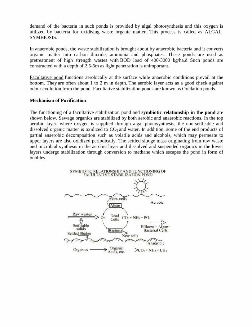
demand of the bacteria in such ponds is provided by algal photosynthesis and this oxygen is
utilized by bacteria for oxidising waste organic matter. This process is called as ALGAL-
SYMBIOSIS.
In anaerobic ponds, the waste stabilization is brought about by anaerobic bacteria and it converts
organic matter into carbon dioxide, ammonia and phosphates. These ponds are used as
pretreatment of high strength wastes with BOD load of 400-3000 kg/ha.d Such ponds are
constructed with a depth of 2.5-5m as light penetration is unimportant.
Facultative pond functions aerobically at the surface while anaerobic conditions prevail at the
bottom. They are often about 1 to 2 m in depth. The aerobic layer acts as a good check against
odour evolution from the pond. Facultative stabilization ponds are known as Oxidation ponds.
Mechanism of Purification
The functioning of a facultative stabilization pond and symbiotic relationship in the pond are
shown below. Sewage organics are stabilized by both aerobic and anaerobic reactions. In the top aerobic layer, where oxygen is supplied through algal photosynthesis, the non-settleable and
dissolved organic matter is oxidized to CO2 and water. In addition, some of the end products of
partial anaerobic decomposition such as volatile acids and alcohols, which may permeate to upper layers are also oxidized periodically. The settled sludge mass originating from raw waste
and microbial synthesis in the aerobic layer and dissolved and suspended organics in the lower layers undergo stabilization through conversion to methane which escapes the pond in form of
bubbles.

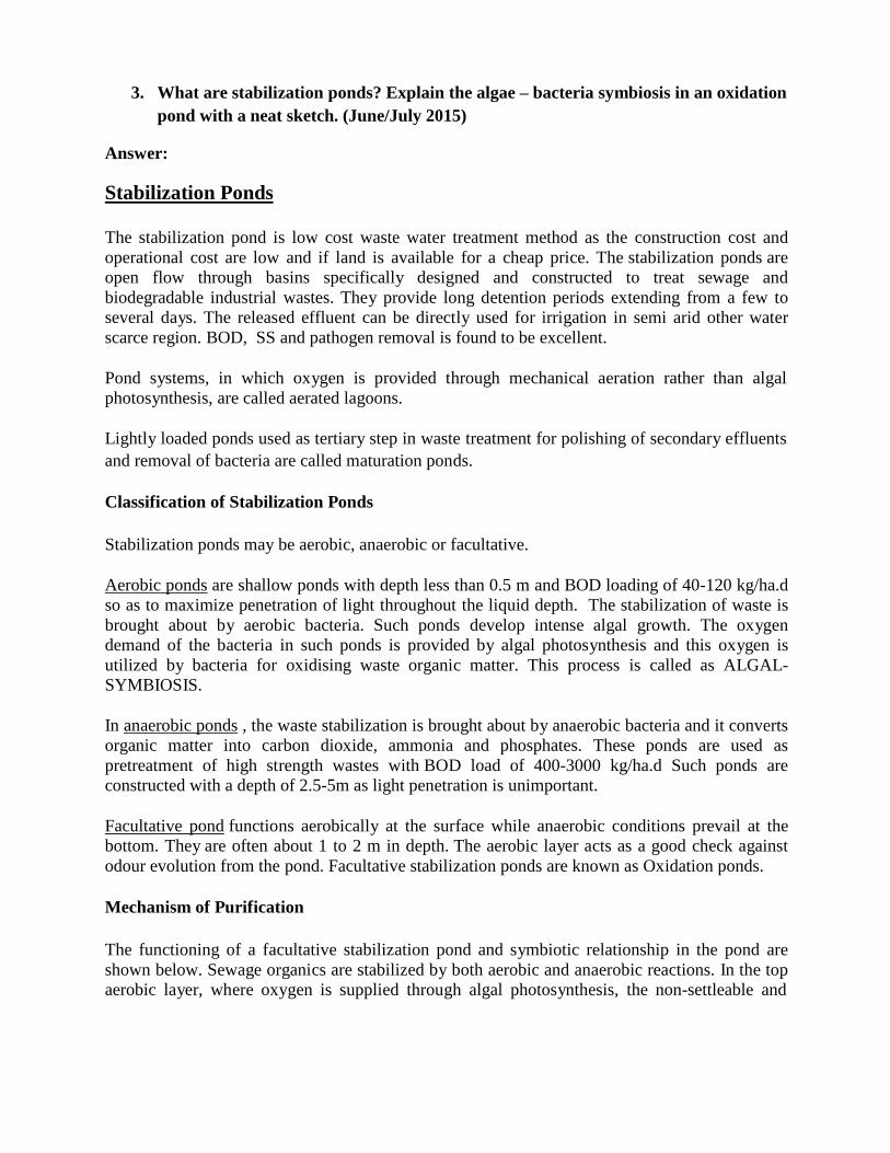
3. What are stabilization ponds? Explain the algae – bacteria symbiosis in an oxidation
pond with a neat sketch. (June/July 2015)
Answer:
Stabilization Ponds
The stabilization pond is low cost waste water treatment method as the construction cost and
operational cost are low and if land is available for a cheap price. The stabilization ponds are
open flow through basins specifically designed and constructed to treat sewage and
biodegradable industrial wastes. They provide long detention periods extending from a few to
several days. The released effluent can be directly used for irrigation in semi arid other water
scarce region. BOD, SS and pathogen removal is found to be excellent.
Pond systems, in which oxygen is provided through mechanical aeration rather than algal
photosynthesis, are called aerated lagoons.
Lightly loaded ponds used as tertiary step in waste treatment for polishing of secondary effluents
and removal of bacteria are called maturation ponds.
Classification of Stabilization Ponds
Stabilization ponds may be aerobic, anaerobic or facultative.
Aerobic ponds are shallow ponds with depth less than 0.5 m and BOD loading of 40-120 kg/ha.d
so as to maximize penetration of light throughout the liquid depth. The stabilization of waste is
brought about by aerobic bacteria. Such ponds develop intense algal growth. The oxygen
demand of the bacteria in such ponds is provided by algal photosynthesis and this oxygen is
utilized by bacteria for oxidising waste organic matter. This process is called as ALGAL-
SYMBIOSIS.
In anaerobic ponds , the waste stabilization is brought about by anaerobic bacteria and it converts
organic matter into carbon dioxide, ammonia and phosphates. These ponds are used as
pretreatment of high strength wastes with BOD load of 400-3000 kg/ha.d Such ponds are
constructed with a depth of 2.5-5m as light penetration is unimportant.
Facultative pond functions aerobically at the surface while anaerobic conditions prevail at the
bottom. They are often about 1 to 2 m in depth. The aerobic layer acts as a good check against
odour evolution from the pond. Facultative stabilization ponds are known as Oxidation ponds.
Mechanism of Purification
The functioning of a facultative stabilization pond and symbiotic relationship in the pond are
shown below. Sewage organics are stabilized by both aerobic and anaerobic reactions. In the top
aerobic layer, where oxygen is supplied through algal photosynthesis, the non-settleable and
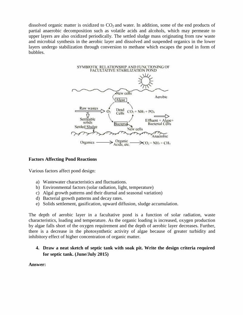
dissolved organic matter is oxidized to CO2 and water. In addition, some of the end products of
partial anaerobic decomposition such as volatile acids and alcohols, which may permeate to upper layers are also oxidized periodically. The settled sludge mass originating from raw waste and microbial synthesis in the aerobic layer and dissolved and suspended organics in the lower layers undergo stabilization through conversion to methane which escapes the pond in form of bubbles.
Factors Affecting Pond Reactions
Various factors affect pond design:
a) Wastewater characteristics and fluctuations.
b) Environmental factors (solar radiation, light, temperature)
c) Algal growth patterns and their diurnal and seasonal variation)
d) Bacterial growth patterns and decay rates.
e) Solids settlement, gasification, upward diffusion, sludge accumulation.
The depth of aerobic layer in a facultative pond is a function of solar radiation, waste
characteristics, loading and temperature. As the organic loading is increased, oxygen production
by algae falls short of the oxygen requirement and the depth of aerobic layer decreases. Further,
there is a decrease in the photosynthetic activity of algae because of greater turbidity and
inhibitory effect of higher concentration of organic matter.
4. Draw a neat sketch of septic tank with soak pit. Write the design criteria required
for septic tank. (June/July 2015)
Answer:
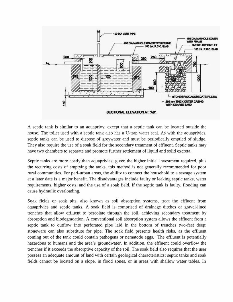
A septic tank is similar to an aquaprivy, except that a septic tank can be located outside the
house. The toilet used with a septic tank also has a U-trap water seal. As with the aquaprivies,
septic tanks can be used to dispose of greywater and must be periodically emptied of sludge.
They also require the use of a soak field for the secondary treatment of effluent. Septic tanks may
have two chambers to separate and promote further settlement of liquid and solid excreta.
Septic tanks are more costly than aquaprivies; given the higher initial investment required, plus
the recurring costs of emptying the tanks, this method is not generally recommended for poor
rural communities. For peri-urban areas, the ability to connect the household to a sewage system
at a later date is a major benefit. The disadvantages include faulty or leaking septic tanks, water
requirements, higher costs, and the use of a soak field. If the septic tank is faulty, flooding can
cause hydraulic overloading.
Soak fields or soak pits, also known as soil absorption systems, treat the effluent from
aquaprivies and septic tanks. A soak field is comprised of drainage ditches or gravel-lined
trenches that allow effluent to percolate through the soil, achieving secondary treatment by
absorption and biodegradation. A conventional soil absorption system allows the effluent from a
septic tank to outflow into perforated pipe laid in the bottom of trenches two-feet deep;
stoneware can also substitute for pipe. The soak field presents health risks, as the effluent
coming out of the tank could contain pathogens or nematode eggs. The effluent is potentially
hazardous to humans and the area‟s groundwater. In addition, the effluent could overflow the
trenches if it exceeds the absorptive capacity of the soil. The soak field also requires that the user
possess an adequate amount of land with certain geological characteristics; septic tanks and soak
fields cannot be located on a slope, in flood zones, or in areas with shallow water tables. In
addition, areas with non-permeable soil do not allow the percolation necessary to achieve
secondary treatment.
Other natural treatment processes of waste water treatment are phyto-remediation: planting the
trenches of a soak field with native semi-aquatic plants, flowers, or vegetables. This process
ensures that the soak field maintains equilibrium and will not overflow; provides a safe conduit
for effluent; and also produces end products that can be decorative.
A septic tank is a water tight single storied, underground, horizontal continuous flow
sedimentation tank in which sewage is retained sufficiently long to permit 60-70% of suspended
solids to settle in the form of sludge at the bottom of the tank. Some of the lighter solids
including grease and fat rise to the surface of the sewage to form floating scum. The scum and
the sludge so formed are then retained with the sewage in the tank for a several months during
which they are decomposed by the process called sludge digestion. Consequently, there is a
reduction in volume of the sludge to be disposed off. There will be release of gases like CO2, CH4
and H2S. The effluent although clarified to some extent will still contain considerable amount of
dissolved and suspended putrescible organic solids and viable pathogens and therefore disposal
of effluent merits careful consideration. Because of the unsatisfactory quality of the effluent and
also difficulty to providing a proper disposal system for the effluent, septic tanks are
recommended only for individual homes and small communities and institutions whose
contributory population does not exceed 300.
5. Explain the different low cost waste water treatment methods. (Dec 14/Jan 15) Answer:
Low Cost Waste Treatment Method Many low-cost methods are able to treat excreta and sewage so that it can be reused. Reducing
pathogens, particularly human intestinal nematodes and fecal bacteria, is the most important step
in treating human waste. The WHO‟s guideline limit for fecal coliform bacteria is 1000 per 100
milliliters and the limit of nematodes is to be no more than one egg per liter. Once these
standards are met, human excreta can be reused as fertilizer or for aquaculture. To provide the
technology at a low cost and ensure sustainability, the facilities must be constructed out of
locally available materials, adhere to the land-use patterns of the community, and conform to the
geotechnical demands of the area. Human excreta do not necessarily have to be waste products,
but can be reused for agriculture or aquaculture. The desire of the community to reuse excreta
will affect the choices and operation of a sanitation program. Sanitation programs cannot simply
be transplanted, but must be molded to fit the needs of each community, and thus they rely on
innovation.
Septic Tank: -
A septic tank is similar to an aqua-privy, except that a septic tank can be located outside the
house. The toilet used with a septic tank also has a U-trap water seal. As with the aqua-privies,
septic tanks can be used to dispose of grey-water and must be periodically emptied of sludge.
They also require the use of a soak field for the secondary treatment of effluent. Septic tanks may
have two chambers to separate and promote further settlement of liquid and solid excreta.
Septic tanks are more costly than aqua-privies; given the higher initial investment required, plus
the recurring costs of emptying the tanks, this method is not generally recommended for poor
rural communities. For peri-urban areas, the ability to connect the household to a sewage system
at a later date is a major benefit. The disadvantages include faulty or leaking septic tanks, water
requirements, higher costs, and the use of a soak field. If the septic tank is faulty, flooding can
cause hydraulic overloading.
Soak fields or soak pits, also known as soil absorption systems, treat the effluent from
aquaprivies and septic tanks. A soak field is comprised of drainage ditches or gravel-lined
trenches that allow effluent to percolate through the soil, achieving secondary treatment by
absorption and biodegradation. A conventional soil absorption system allows the effluent from a
septic tank to outflow into perforated pipe laid in the bottom of trenches two-feet deep;
stoneware can also substitute for pipe. The soak field presents health risks, as the effluent
coming out of the tank could contain pathogens or nematode eggs. The effluent is potentially
hazardous to humans and the area‟s groundwater. In addition, the effluent could overflow the
trenches if it exceeds the absorptive capacity of the soil. The soak field also requires that the user
possess an adequate amount of land with certain geological characteristics; septic tanks and soak
fields cannot be located on a slope, in flood zones, or in areas with shallow water tables. In
addition, areas with non-permeable soil do not allow the percolation necessary to achieve
secondary treatment.
Other natural treatment processes of waste water treatment are phyto-remediation: planting the
trenches of a soak field with native semi-aquatic plants, flowers, or vegetables. This process
ensures that the soak field maintains equilibrium and will not overflow; provides a safe conduit
for effluent; and also produces end products that can be decorative.
Stabilization Ponds
The stabilization pond is low cost waste water treatment method as the construction cost and
operational cost are low and if land is available for a cheap price. The stabilization ponds are
open flow through basins specifically designed and constructed to treat sewage and
biodegradable industrial wastes. They provide long detention periods extending from a few to
several days. The released effluent can be directly used for irrigation in semi arid other water
scarce region. BOD, SS and pathogen removal is found to be excellent.
Pond systems, in which oxygen is provided through mechanical aeration rather than algal
photosynthesis, are called aerated lagoons.
Lightly loaded ponds used as tertiary step in waste treatment for polishing of secondary effluents
and removal of bacteria are called maturation ponds.
Classification of Stabilization Ponds
Stabilization ponds may be aerobic, anaerobic or facultative.
Aerobic ponds are shallow ponds with depth less than 0.5 m and BOD loading of 40-120 kg/ha.d
so as to maximize penetration of light throughout the liquid depth. The stabilization of waste is
brought about by aerobic bacteria. Such ponds develop intense algal growth. The oxygen
demand of the bacteria in such ponds is provided by algal photosynthesis and this oxygen is
utilized by bacteria for oxidising waste organic matter. This process is called as ALGAL-
SYMBIOSIS.
In anaerobic ponds , the waste stabilization is brought about by anaerobic bacteria and it converts
organic matter into carbon dioxide, ammonia and phosphates. These ponds are used as
pretreatment of high strength wastes with BOD load of 400-3000 kg/ha.d Such ponds are
constructed with a depth of 2.5-5m as light penetration is unimportant.
Facultative pond functions aerobically at the surface while anaerobic conditions prevail at the
bottom. They are often about 1 to 2 m in depth. The aerobic layer acts as a good check against
odour evolution from the pond. Facultative stabilization ponds are known as Oxidation ponds.
6. Discuss the importance of reuse and recycling of sewage with their merits and
demerits in this modernized society. (Dec 14/Jan 15)
Answer:
Reuse and Recycle of Waste water
Reclaimed water is an important component of wise water management. Reclaimed water is
derived from domestic wastewater and small amounts of industrial process water or storm water.
The process of reclaiming water, sometimes called water recycling or water reuse, involves a
highly engineered, multi-step treatment process that speeds up nature's restoration of water
quality. The process provides a high-level of disinfection and reliability to assure that only water
meeting stringent requirements leaves the treatment facility.
Onsite wastewater management systems provide treatment and recycling/disposal of:
greywater – shower, bath, hand basins, clothes washing machine, laundry troughs and the
kitchen
blackwater – toilet waste (water-flush, incineration or dry composting systems)
sewage – combined greywater and blackwater
Wastewater treated to primary quality is only suitable for disposal below ground via soil
absorption trenches, mounds and evapo-transpiration beds or trenches. Wastewater treated to
secondary quality may also be dispersed to land via pressure-compensating subsurface irrigation.
Greywater that has been treated to advanced-secondary quality can be used in the home for toilet
flushing and cold water use in the clothes washing machine as well as surface and subsurface
irrigation.
Grey water is reusable wastewater from residential, commercial and industrial bathroom sinks,
bath tub shower drains, and clothes washing equipment drains. It is reused onsite, typically for
landscape irrigation. Use of non toxic and low-sodium soap and personal care products is
required to protect vegetation when reusing grey water for irrigation.
Recycled water can satisfy most water demands, as long as it is adequately treated to ensure
water quality appropriate for the use. In uses where there is a greater chance of human exposure
to the water, more treatment is required. As for any water source that is not properly treated,
health problems could arise from drinking or being exposed to recycled water if it contains
disease-causing organisms or other contaminants. EPA regulates many aspects of wastewater
treatment and drinking water quality.
Uses for Recycled Water
Recycled water is most commonly used for non-potable (not for drinking) purposes, such as
1. Agriculture
2. Landscape and Golf course irrigation
3. Public parks
4. Cooling water for power plants and oil refineries
5. Processing water for mills, plants
6. Toilet flushing
7. Dust control,
8. Construction activities
9. Concrete mixing
10. Artificial lakes
Although most water recycling projects have been developed to meet nonpotable water demands,
a number of projects use recycled water indirectly for potable purposes. These projects include
recharging ground water aquifers and augmenting surface water reservoirs with recycled water.
In ground water recharge projects, recycled water can be spread or injected into ground water
aquifers to augment ground water supplies, and to prevent salt water intrusion in coastal areas.
The use of grey water at decentralized sites (see definition) for landscape irrigation and toilet
flushing reduces the amount of potable water distributed to these sites, the amount of fertilizer
needed, and the amount of wastewater generated, transported, and treated at wastewater
treatment facilities. In other words, water reuse saves water, energy, and money. Decentralized
water reuse systems are being used more in the arid west where long term drought conditions
exist. Successful grey water systems have been operating for many years,. They can meet up to
50% of a property's water needs by supplying water for landscaping. Recycling gray water saves
fresh potable water for other uses, reduces the volume of wastewater going to septic systems and
wastewater treatment plants, and increases infrastructure capacity for new users.
Advantages of Reuse &Recycling
1. Protects Environment: The foremost benefit or recycling is that it helps in protecting the
environment in the most balanced manner. While many trees are cut down continually, recycled
paper made from certain trees is re-used repeatedly to minimize felling/ deforestation. With re-
cycled paper as an outstanding example, a number of other natural resources can be reused this
way.
2. Reduces Energy Consumption: A large amount of energy is consumed by processing raw
materials at the time of manufacture. Recycling helps to minimize energy consumption, which is
crucial for massive production, such mining or refining. This also makes the production process
very cost-effective and beneficial for manufacturers.
3. Reduces Pollution: Industrial waste today is the main source of all types of pollution.
Recycling of industrial products such as cans, chemical, plastics helps to cut down pollution
levels considerably, as these materials are re-used, instead of throwing them away irresponsibly.
4. Reduces Global Warming: Recycling helps to alleviate global warming and its ill effects.
Massive waste is burned in heaps which produces large amount of greenhouse gas emissions
such as CO2 and CFC‟s. Recycling ensure that the burning process is minimized and any waste
is re-generated as a useful product with no or minimal harmful impact on the environment.
Recycling produces less greenhouse gases as industries burn fewer fossil fuels for eco-friendly
products.
5. Judicial and Sustainable use of Resources: Recycling promotes judicial and sustainable use of
resources. This process ensures that there is no discriminate use of any material when available
in plenty in the present. Recycling is encouraged at all levels, starting from school to corporate
offices and at international levels. This means we can preserve all precious resources for our
future generation, without any compromise in the present.
6. Conserves Natural Resources: If old and used materials are not recycled, the new products are
made from extracting fresh raw materials from beneath the earth through mining and extraction.
Recycling helps in conserving important raw materials and protects natural habitats for the
future. Conserving natural resources such as wood, water and minerals ensures its optimum use.
7. Reduces Amount of Waste to Landfills: Recycling old and waste products into new products
reduces the amount of waste that go to landfills. This helps in reducing water and land pollution
as landfills are a major source in contributing to destruction of natural environment. Recycling
programs keep 70 tons of waste from being deposited into landfills every year.
8. Create Green Jobs: Recycling is good for the environment and apart from that it also creates
green jobs. According to the U.S. Bureau of Labor Statistics, green goods and services accounted
for 3.1 million jobs in the United States by 2010.
Disadvantages of Reuse &Recycling
1. Not always Cost Effective: Recycling is not always cost-effective. Sometimes, there may be a
need to establish separate factories to process reusable products. This may create more pollution
in terms of cleaning, storage and transportation.
2. Recycled Products May not Last for Long: Recycled products are always not of durable
quality. Such items are mostly made of trashed waste, picked up from heaps other waste products
which are of fragile or overly used. For this reason, recycled products are cheap and last for a
shorter period.
3. Unsafe and Unhygienic Recycling Sites: Recycling sites are often unsafe and unhygienic.
Places where all sorts of waste are dumped are conducive for debris formation and spread of
disease and other dangers caused by harmful chemicals and waste. This not only causes
widespread pollution but is harmful for dedicated people who recycle such products. Such waste
if mixed with water, leads to leachate formation and leads to toxication of water bodies including
drinking water.
7. Arrive at the dimensions of an oxidation pond to treat 1 MLD of sewage received
from a suburb of a city, located in an area of hot climate, the BOD of sewage being
320 mg/lt. (Dec 14/Jan 15)
Answer:
Total BOD load = 1 x 10⁶
l/d x320mg/l = 320 x 106
mg/d = 320 kg/d
Assuming a BOD loading of 300 kg/hec/day for an area located in hot climate.
Pond area = Total BOD/BOD loading = 320 kg/d/ 300 kg/hec/day = 1.067 ha = 10667 m2
Detention Time
Winter, k15 = 0.25 x 1.06 15-20
= 0.187/d
Summer, k35 = 0.25 x 1.0635-20
= 0.6/d
Detention time, T = kt/k15
For BOD removal efficiency of 85% and dispersion factor of 0.5, kt = 3
T = 3/0.187 = 16.04 days (winter) T = 3/0.6 = 5 days (summer)
Pond Volume = Flow x Detention time = 1 x 10³
m3
x 16.04 =16040 m3
Pond water depth = Pond volume/Pond area = 16040/10667 = 1.5 m L = 2.5 B
A = L x B
B = √A/2.5 = √10667/2.5
B = 65.32 say 65 m
L = 164.1 say 164 m Overall dimension of the pond = 164 m x 65 m x (1.5 + 0.3 m Free board)
8. Design a septic tank for a small colony of 200 persons provided with a water supply
of 135 lpcd. Assume the necessary data for the design. The data available are: MDD
is twice the ADD, 80% of water supply becomes spent, detention time of 24 hours,
length to breadth ratio is 1:3. Draw a line diagram showing designed dimensions.
( Dec 14/Jan15)
Answer: Qsewage = (200 x 135 x 2) x 0.8 = 43, 200 l/d Volume = (43,000/24) x 24 = 43.2 m
Total volume of sludge = 30 x 200 x 1% = 6 m3
Total capacity of tank = 43.2 + 6 = 49.2 m3
Assuming a depth of tank = 1.5 + 0.3 free board
Surface area, A = 49.2/1.5 = 32.8 m2
Length = 3 x Breadth
A = L x B
B = √A/3
B = 3.31 say 3.3 m
L = 9.93 say 10 m L x B x D = 10 m x 3.3 m x 1.8 m
3