Embed Size (px)
Citation preview

Questions and Answer for Bulk Material Bin Covers November 18, 2016 Page 1 of 2
Questions and Answers For the RFP for Bulk Material Bin Cover
1. Does the City have “Record Drawings” or Construction Drawings of the existing bins? a. Yes, please contact Joseph Bruzzone at [email protected] for a copy.
2. Is there a recent Geotechnical Investigation and Report for the Site?
a. A Geotechnical report for the recent water tank construction in the same yard is available for review. Please contact Joseph Bruzzone at [email protected] for a copy.
3. Is the structural canopy to cover the bins and the proposed 50 cubic yard metal recycling dumpster or will it extend some distance in front of the existing bins?
a. The City believes that this issue should be left to the selected proposer to determine if an extended overhang is appropriate to achieve the projects goals.
4. Are the walls at the rear and the sides next to the outside bins to be solid? a. The City believes that this issue should be left to the selected proposer to
determine if solid walls are appropriate to achieve the projects goals.
5. Do you have specifications of the dump trucks and loaders to be used during the daily operation?
a. The city is currently gathering this information. Unfortunately it was not ready by the time that this document was due to be posted. If any proposer is interested in this information they may request that an email be sent to them by contacting Joseph Bruzzone at [email protected]
6. Are site utility plans available? a. Yes, Please Contact Joseph Bruzzone at [email protected] for a copy.
7. Can electrical power for the new structural canopy come from the existing power poles
behind the bins? a. The electrical power will have to come from the existing service for the site.
Please see the Utility plans for further information.
8. Do you want the runoff from the material bin area to go to the sanitary sewer or a storage tank?
a. The City believes that this issue should be left to the selected proposer to determine how the runoff should be handled.
Questions and Answer for Bulk Material Bin Covers November 18, 2016 Page 2 of 2
9. Is hazard waste or material to be temporally stored in the bin area? a. No.
10. May we have more time to submit the proposal?
a. Yes, The Deadline has been extended to December 2, 2016.
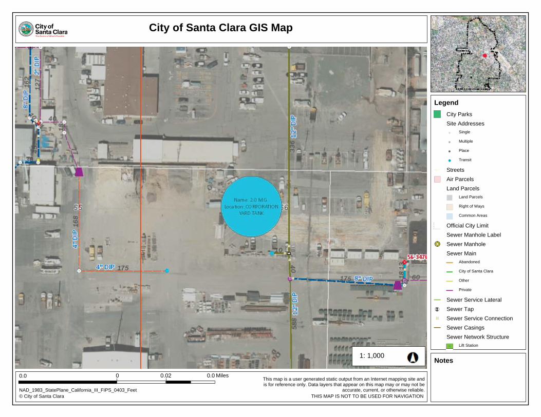
City of Santa Clara GIS Map
This map is a user generated static output from an Internet mapping site andis for reference only. Data layers that appear on this map may or may not be
accurate, current, or otherwise reliable.
1,000
© City of Santa Clara
0.0
THIS MAP IS NOT TO BE USED FOR NAVIGATION
1:
NAD_1983_StatePlane_California_III_FIPS_0403_Feet
Miles0.00
Notes
Legend
0.02
City Parks
Site Addresses
Single
Multiple
Place
Transit
Streets
Air Parcels
Land Parcels
Land Parcels
Right of Ways
Common Areas
Official City Limit
Sewer Manhole Label
Sewer Manhole
Sewer Main
Abandoned
City of Santa Clara
Other
Private
Sewer Service Lateral
Sewer Tap
Sewer Service Connection
Sewer Casings
Sewer Network Structure
Lift Station
I:\W
ater\C
AD
\A
utoC
ad D
raw
ings\Job D
raw
ings\1651 M
artin A
ve (N
ew
W
alsh T
ank) (J30247W
3206)\D
raw
ing\A
s-B
uilt\N
ew
W
alsh T
ank A
s-B
uilt (7-21-2015).dw
g P
lot style: 14-W
3206-B
LK
.ctb
P
lot date: 8/5/2015
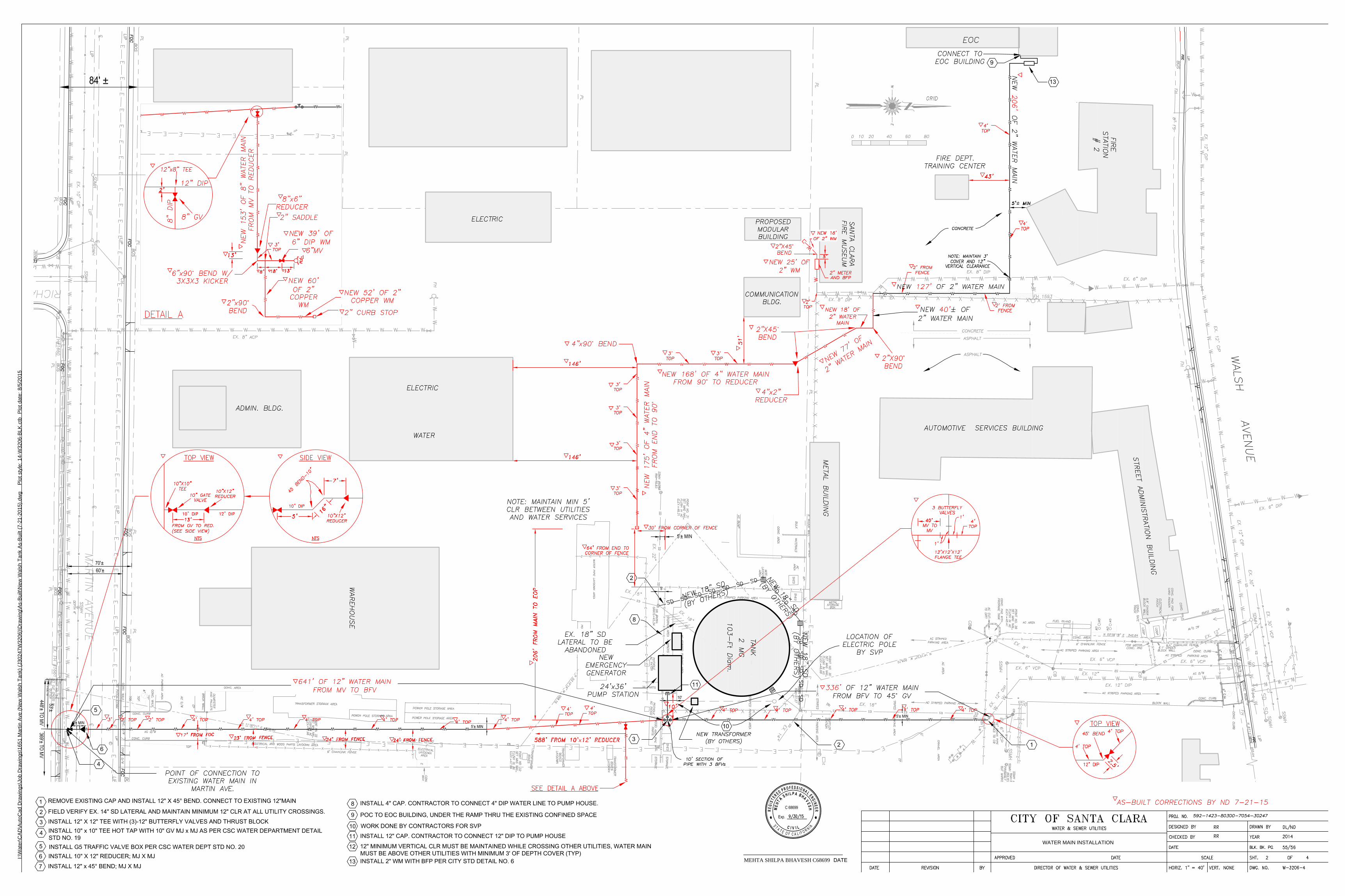
MEHTA SHILPA BHAVESH C68699
WATER MAIN INSTALLATION
CITY OF SANTA CLARA CORP YARD WATER TANK 138-6-1
Page i
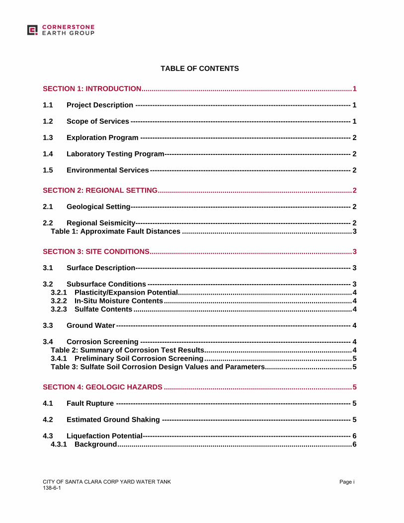
TABLE OF CONTENTS
SECTION 1: INTRODUCTION ........................................................................................................ 1
1.1 Project Description ----------------------------------------------------------------------------------------- 1
1.2 Scope of Services ------------------------------------------------------------------------------------------- 1
1.3 Exploration Program --------------------------------------------------------------------------------------- 2
1.4 Laboratory Testing Program ----------------------------------------------------------------------------- 2
1.5 Environmental Services ----------------------------------------------------------------------------------- 2
SECTION 2: REGIONAL SETTING ................................................................................................ 2
2.1 Geological Setting ------------------------------------------------------------------------------------------- 2
2.2 Regional Seismicity ----------------------------------------------------------------------------------------- 2 Table 1: Approximate Fault Distances .................................................................................... 3
SECTION 3: SITE CONDITIONS .................................................................................................... 3
3.1 Surface Description ----------------------------------------------------------------------------------------- 3
3.2 Subsurface Conditions ------------------------------------------------------------------------------------ 3 3.2.1 Plasticity/Expansion Potential...................................................................................... 4 3.2.2 In-Situ Moisture Contents ............................................................................................. 4 3.2.3 Sulfate Contents ............................................................................................................ 4
3.3 Ground Water ------------------------------------------------------------------------------------------------- 4
3.4 Corrosion Screening --------------------------------------------------------------------------------------- 4 Table 2: Summary of Corrosion Test Results......................................................................... 4 3.4.1 Preliminary Soil Corrosion Screening ......................................................................... 5 Table 3: Sulfate Soil Corrosion Design Values and Parameters ........................................... 5
SECTION 4: GEOLOGIC HAZARDS ............................................................................................. 5
4.1 Fault Rupture ------------------------------------------------------------------------------------------------- 5
4.2 Estimated Ground Shaking ------------------------------------------------------------------------------ 5
4.3 Liquefaction Potential -------------------------------------------------------------------------------------- 6 4.3.1 Background .................................................................................................................... 6
CITY OF SANTA CLARA CORP YARD WATER TANK 138-6-1
Page ii
4.3.2 Analysis .......................................................................................................................... 6 4.3.3 Summary ........................................................................................................................ 7 4.3.4 Ground Rupture Potential ............................................................................................. 7
4.4 Lateral Spreading -------------------------------------------------------------------------------------------- 7
4.5 Seismic Settlement/Unsaturated Sand Shaking -------------------------------------------------- 7
4.6 Flooding -------------------------------------------------------------------------------------------------------- 8
SECTION 5: CONCLUSIONS ......................................................................................................... 8
5.1 Summary ------------------------------------------------------------------------------------------------------- 8 5.1.1 Potential for Liquefaction-Induced Settlements ......................................................... 8 5.1.2 Potential for Significant Static and Seismic Settlements .......................................... 9 5.1.3 Shallow Ground Water .................................................................................................. 9 5.1.4 Expansive Soils ............................................................................................................. 9 5.1.5 Soil Corrosion Potential ................................................................................................ 9
5.2 Plans and Specifications Review --------------------------------------------------------------------- 10
5.3 Construction Observation and Testing ------------------------------------------------------------- 10
SECTION 6: EARTHWORK ......................................................................................................... 10
6.1 Site Demolition, Clearing and Preparation --------------------------------------------------------- 10 6.1.1 Demolition of Existing Slabs, Foundations and Pavements ................................... 10 6.1.2 Abandonment of Existing Utilities ............................................................................. 10
6.2 Removal of Existing Fills -------------------------------------------------------------------------------- 11
6.3 Temporary Cut and Fill Slopes ------------------------------------------------------------------------- 11
6.4 Subgrade Preparation ------------------------------------------------------------------------------------- 11
6.5 Subgrade Stabilization Measures --------------------------------------------------------------------- 11 6.5.1 Scarification and Drying ............................................................................................. 12 6.5.2 Removal and Replacement ......................................................................................... 12 6.5.3 Chemical Treatment .................................................................................................... 12
6.6 Material for Fill ----------------------------------------------------------------------------------------------- 12 6.6.1 Re-Use of On-site Soils ............................................................................................... 12 6.6.2 Re-Use of On-Site Site Improvements ....................................................................... 13 6.6.3 Potential Import Sources ............................................................................................ 13 6.6.4 Non-Expansive Fill Using Lime Treatment ................................................................ 13
6.7 Compaction Requirements ------------------------------------------------------------------------------ 13 Table 4: Compaction Requirements ...................................................................................... 14
CITY OF SANTA CLARA CORP YARD WATER TANK 138-6-1
Page iii
6.7.1 Construction Moisture Conditioning ......................................................................... 15
6.8 Trench Backfill ---------------------------------------------------------------------------------------------- 15
6.9 Site Drainage ------------------------------------------------------------------------------------------------- 15
SECTION 7: FOUNDATIONS ....................................................................................................... 16
7.1 Summary of Recommendations ----------------------------------------------------------------------- 16
7.2 Seismic Design Criteria ---------------------------------------------------------------------------------- 16 Table 5: CBC Site Categorization and Site Coefficients ...................................................... 17
7.3 Shallow Foundations -------------------------------------------------------------------------------------- 17 7.3.1 Spread Footings .......................................................................................................... 17 7.3.2 Footing Settlement ...................................................................................................... 18 Table 6: Assumed Structural Loading ................................................................................... 18 7.3.3 Lateral Loading ............................................................................................................ 18 7.3.4 Spread Footing Construction Considerations .......................................................... 18 7.3.5 Reinforced Concrete Mat Foundations ...................................................................... 19 7.3.6 Mat Foundation Settlement......................................................................................... 19 7.3.7 Lateral Loading ............................................................................................................ 19 7.3.8 Mat Foundation Construction Considerations ......................................................... 19 7.3.9 Mat Modulus of Soil Subgrade Reaction ................................................................... 20
7.4 Deep Foundations ------------------------------------------------------------------------------------------ 20 7.4.1 Driven Piles .................................................................................................................. 20 Table 7: Ultimate Lateral Load Capacity Driven Piles .......................................................... 21 7.4.2 Augercast Piles ............................................................................................................ 23 Table 8: Ultimate Lateral Load Capacity APG Piles ............................................................. 24
SECTION 8: CONCRETE SLABS AND PEDESTRIAN PAVEMENTS ....................................... 24
8.1 Interior Slabs-on-Grade ---------------------------------------------------------------------------------- 24
8.2 Interior Slabs Moisture Protection Considerations --------------------------------------------- 24
8.3 Exterior Flatwork ------------------------------------------------------------------------------------------- 25
SECTION 9: VEHICULAR PAVEMENTS ..................................................................................... 25
9.1 Asphalt Concrete ------------------------------------------------------------------------------------------- 25 Table 9: Asphalt Concrete Pavement Recommendations ................................................... 26
9.2 Portland Cement Concrete ------------------------------------------------------------------------------ 26 Table 10: PCC Pavement Recommendations ....................................................................... 26
CITY OF SANTA CLARA CORP YARD WATER TANK 138-6-1
Page iv
SECTION 10: LIMITATIONS ........................................................................................................ 27
SECTION 11: REFERENCES ....................................................................................................... 28 FIGURE 1: VICINITY MAP FIGURE 2: SITE PLAN FIGURE 3: REGIONAL FAULT MAP FIGURE 4A TO 4B: LIQUEFACTION ANALYSIS SUMMARY – CPT-01 TO CPT-02 FIGURE 5: PILE CAPACITY CHART APPENDIX A: FIELD INVESTIGATION APPENDIX B: LABORATORY TEST PROGRAM APPENDIX C: LIQUEFACTION ANALYSES CALCULATIONS
CITY OF SANTA CLARA CORP YARD WATER TANK 138-6-1
Page 1
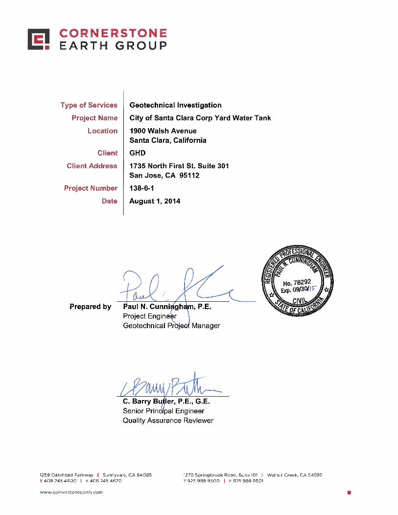
Type of Services Geotechnical Investigation
Project Name City of Santa Clara Corp Yard Water Tank Location 1900 Walsh Avenue
Santa Clara, California
SECTION 1: INTRODUCTION This geotechnical report was prepared for the sole use of GHD for the City of Santa Clara Corp Yard Water Tank in Santa Clara, California. The location of the site is shown on the Vicinity Map, Figure 1. For our use, we were provided with the following documents:
Portion of Aerial Photo with tank location superimposed, undated, untitled.
Geotechnical Investigation, “Proposed Pedestal Tower Water Tank, Walsh Road, Santa Clara, California,” prepared by Bay Area Geotechnical Group, dated April 14, 2003.
1.1 PROJECT DESCRIPTION The project will consist of construction of a 2-million-gallon water tank within the City of Santa Clara Corporation Yard surrounded by an access road. The water tank will be of welded steel-frame construction. Additional piping and a small pump house building are also planned. Average areal loads are anticipated to be on the order of 2,200 psf under the tank footprint, while the pump building may have loads of up to 2 kips per lineal foot along a continuous perimeter footing. Grading is anticipated to be minor, with cuts and fills on the order of 1 to 3 feet. 1.2 SCOPE OF SERVICES Our scope of services was presented in our proposal dated June 19, 2014 and consisted of field and laboratory programs to evaluate physical and engineering properties of the subsurface soils, engineering analysis to prepare recommendations for site work and grading, building foundations, flatwork, retaining walls, and pavements, and preparation of this report. Brief descriptions of our exploration and laboratory programs are presented below.
CITY OF SANTA CLARA CORP YARD WATER TANK 138-6-1
Page 2
1.3 EXPLORATION PROGRAM Field exploration consisted of two borings drilled on July 2, 2014 with truck-mounted, hollow-stem auger drilling equipment and two (2) Cone Penetration Tests (CPTs) advanced on June 27, 2014. The borings were drilled to depths of 15 to 45 feet; the CPTs were advanced to depths of 50 to 75 feet. One of the borings (Boring EB-1) was advanced adjacent to CPT-1 for direct evaluation of physical samples to correlated soil behavior. The borings and CPTs were backfilled with cement grout in accordance with local requirements; exploration permits were obtained as required by local jurisdictions. The approximate locations of our exploratory borings are shown on the Site Plan, Figure 2. Details regarding our field program are included in Appendix A. 1.4 LABORATORY TESTING PROGRAM In addition to visual classification of samples, the laboratory program focused on obtaining data for foundation design and seismic ground deformation estimates. Testing included moisture contents, dry densities, washed sieve analyses, Plasticity Index tests, and consolidation tests. Details regarding our laboratory program are included in Appendix B. 1.5 ENVIRONMENTAL SERVICES Environmental services were not requested for this project. If environmental concerns are determined to be present during future evaluations, the project environmental consultant should review our geotechnical recommendations for compatibility with the environmental concerns. SECTION 2: REGIONAL SETTING 2.1 GEOLOGICAL SETTING The site is located within the Santa Clara Valley, which is a broad alluvial plane between the Santa Cruz Mountains to the southwest and west, and the Diablo Range to the northeast. The San Andreas Fault system, including the Monte Vista-Shannon Fault, exists within the Santa Cruz Mountains and the Hayward and Calaveras Fault systems exist within the Diablo Range. Alluvial soil thicknesses in the area of Santa Clara and north San Jose range from about 300 to greater than 700 feet (Rogers & Williams, 1974). 2.2 REGIONAL SEISMICITY The San Francisco Bay area is one of the most seismically active areas in the Country. While seismologists cannot predict earthquake events, the U.S. Geological Survey’s Working Group on California Earthquake Probabilities 2007 estimates there is a 63 percent chance of at least one magnitude 6.7 or greater earthquake occurring in the Bay Area region between 2007 and 2036. As seen with damage in San Francisco and Oakland due to the 1989 Loma Prieta earthquake that was centered about 50 miles south of San Francisco, significant damage can
CITY OF SANTA CLARA CORP YARD WATER TANK 138-6-1
Page 3
occur at considerable distances. Higher levels of shaking and damage would be expected for earthquakes occurring at closer distances. The faults considered capable of generating significant earthquakes are generally associated with the well-defined areas of crustal movement, which trend northwesterly. The table below presents the State-considered active faults within 25 kilometers of the site. Table 1: Approximate Fault Distances
Fault Name
Distance (miles) (kilometers)
Hayward (Southeast Extension) 7.0 11.3 Monte Vista-Shannon 8.0 12.9
Hayward (Total Length) 9.3 15.0 Calaveras 10.2 16.5
San Andreas (1906) 10.7 17.3 A regional fault map is presented as Figure 3, illustrating the relative distances of the site to significant fault zones. SECTION 3: SITE CONDITIONS 3.1 SURFACE DESCRIPTION The site is located in the existing City of Santa Clara Corporation Yard. The area where the tank is proposed is relatively flat and paved with asphaltic concrete. From our site visit observations, most of the site is currently used as a storage area for extra materials and city maintenance vehicle parking. Surface pavements generally consisted of 2 inches of asphalt concrete over 6½ to 7½ inches of aggregate base. Based on visual observations, the existing pavements are in good condition. 3.2 SUBSURFACE CONDITIONS Below the surface pavements, our explorations generally encountered hard to very stiff, high plasticity clays to between 7 and 9 feet underlain by several feet of stiff to very stiff lean clay. In EB-1 we encountered 6 feet of medium dense sand with variable amounts of fines and gravels from 11 to 17 feet below grade. Below this, we encountered stiff to very stiff high plasticity clay to approximately 23 feet followed by stiff to very stiff lean clay with some thin layers of medium dense clayey sand to the terminal depth of the boring at 45 feet. Below the maximum depth of our borings, our CPT’s encountered two dense layers of sand, ranging from about 6 to 7 feet thick, with correlated SPT blow counts of 40 to 50 per foot, beginning at 43 feet and 56 feet, respectively. These sands were underlain by stiff clays to 75 feet, the maximum depth explored.
CITY OF SANTA CLARA CORP YARD WATER TANK 138-6-1
Page 4
3.2.1 Plasticity/Expansion Potential We performed one Plasticity Index (PI) tests on a representative sample of near-surface soil to evaluate the expansion potential of surficial soils. Results of the surficial PI test indicated a PI of 31, indicating high expansion potential to wetting and drying cycles. 3.2.2 In-Situ Moisture Contents Laboratory testing indicated that the in-situ moisture contents within the upper 10 feet range from 6 to 14 percent over the estimated laboratory optimum moisture. 3.2.3 Sulfate Contents Laboratory testing indicated that the soluble sulfate contents were 42 ppm, indicating negligible corrosion potential to buried concrete. 3.3 GROUND WATER Ground water was encountered in some of our explorations, including EB-1, EB-2, and also inferred by a pore pressure dissipation test in CPT-2, at depths ranging from 8½ to 10 feet below current grades. All measurements were taken at the time of drilling and may not represent the stabilized levels that can be higher than the initial levels encountered. CGS has mapped the historic high ground water in this area at approximately 10 feet; however, a previous geotechnical investigation at the site encountered high ground water at 8 feet below grade (BAGG, 2003). We utilized a high ground water level of 7 feet below grade for our liquefaction analysis. Fluctuations in ground water levels occur due to many factors including seasonal fluctuation, underground drainage patterns, regional fluctuations, and other factors. 3.4 CORROSION SCREENING We tested one sample collected at a depth of 3½ feet for resistivity, pH, soluble sulfates, and chlorides. The laboratory test results are summarized in Table 2. Table 2: Summary of Corrosion Test Results
Sample/Test Location Number
Depth (feet) Soil pH
Minimum Resistivity (1) (ohm-cm)
Chloride (mg/kg)
Sulfate (% dry wt)
EB-2/ 2A 3½ 7.9 2,480 4 0.0042 Notes: (1) Laboratory resistivity measured at 100% saturation Many factors can affect the corrosion potential of soil including moisture content, resistivity, permeability, and pH, as well as chloride and sulfate concentration. Typically, soil resistivity, which is a measurement of how easily electrical current flows through a medium (soil and/or
CITY OF SANTA CLARA CORP YARD WATER TANK 138-6-1
Page 5
water), is the most influential factor. In addition to soil resistivity, chloride and sulfate ion concentrations, and pH also contribute in affecting corrosion potential. 3.4.1 Preliminary Soil Corrosion Screening Based on the laboratory test results summarized in Table 2, the soils are considered moderately corrosive to buried metallic improvements (Palmer, 1989). Other corrosion parameters (pH and chloride content) do not indicate a significant contribution to corrosion potential to buried metallic structures. In accordance with the 2013 CBC, Chapter 19, Section 1904.5, alternative cementitious materials for sulfate exposure shall be in accordance with the following:
▪ ACI 318-08 - Table 4.2.1, and Table 4.3.1 Based on the laboratory test results, no cement type restriction is required, although, in our opinion, it is generally a good idea to include some sulfate resistance and to maintain a relatively low water-cement ratio. We have summarized applicable design values and parameters from ACI 318, Table 4.3.1 below in Table 3 for your information. We recommend the structural engineer and a corrosion engineer be retained to confirm the information provided and for additional recommendations, as required. Table 3: Sulfate Soil Corrosion Design Values and Parameters (1)
Category
Water-Soluble Sulfate (SO4) in Soil (% by weight) Class Severity
Cementitious Materials
(2) S, Sulfate < 0.10 S0 not applicable no type restriction
Notes: (1) above values and parameters are from on ACI 318-08, Table 4.2.1 and Table 4.3.1 (2) cementitious materials are in accordance with ASTM C150, ASTM C595 and ASTM C1157
SECTION 4: GEOLOGIC HAZARDS 4.1 FAULT RUPTURE As discussed above several significant faults are located within 25 kilometers of the site. The site is not located within a State-designated Alquist Priolo Earthquake Fault Zone, or a Santa Clara County Fault Hazard Zone. As shown in Figure 3, no known surface expression of fault traces is thought to cross the site; therefore, fault rupture hazard is not a significant geologic hazard at the site. 4.2 ESTIMATED GROUND SHAKING Moderate to severe (design-level) earthquakes can cause strong ground shaking, which is the case for most sites within the Bay Area. A peak ground acceleration (PGA) was estimated for analysis using a value equal to FPGA*PGA, as allowed in the 2013 edition of the California Building Code. For our liquefaction analysis we used a PGA of 0.5g.
CITY OF SANTA CLARA CORP YARD WATER TANK 138-6-1
Page 6
4.3 LIQUEFACTION POTENTIAL The site is within a State-designated Liquefaction Hazard Zone (CGS, San Jose West Quadrangle, 2003) as well as a Santa Clara County Liquefaction Hazard Zone (Santa Clara County, 2003). Our field and laboratory programs addressed this issue by sampling potentially liquefiable layers to depths of at least 50 feet, performing visual classification on sampled materials, evaluating CPT correlations, and performing various tests to further classify the soil properties. 4.3.1 Background During strong seismic shaking, cyclically induced stresses can cause increased pore pressures within the soil matrix that can result in liquefaction triggering, soil softening due to shear stress loss, potentially significant ground deformation due to settlement within sandy liquefiable layers as pore pressures dissipate, and/or flow failures in sloping ground or where open faces are present (lateral spreading) (NCEER 1998). Limited field and laboratory data is available regarding ground deformation due to settlement; however, in clean sand layers settlement on the order of 2 to 4 percent of the liquefied layer thickness can occur. Soils most susceptible to liquefaction are loose, non-cohesive soils that are saturated and are bedded with poor drainage, such as sand and silt layers bedded with a cohesive cap. 4.3.2 Analysis As discussed in the “Subsurface” section above, several sand layers were encountered below the design ground water depth of 7 feet. Following the procedures in the 2008 monograph, Soil Liquefaction During Earthquakes (Idriss and Boulanger, 2008) and in accordance with CDMG Special Publication 117A guidelines (CDMG, 2008) for quantitative analysis, these layers were analyzed for liquefaction triggering and potential post-liquefaction settlement. These methods compare the ratio of the estimated cyclic shaking (Cyclic Stress Ratio - CSR) to the soil’s estimated resistance to cyclic shaking (Cyclic Resistance Ratio - CRR), providing a factor of safety against liquefaction triggering. Factors of safety less than or equal to 1.3 are considered to be potentially liquefiable and capable of post-liquefaction re-consolidation. The CSR for each layer quantifies the stresses anticipated to be generated due to a design-level seismic event, is based on the peak horizontal acceleration generated at the ground surface discussed in the “Estimated Ground Shaking” section above, and is corrected for overburden and stress reduction factors as discussed in the procedure developed by Seed and Idriss (1971) and updated in the 2008 Idriss and Boulanger monograph. The soil’s CRR is estimated from the in-situ measurements from CPTs and laboratory testing on samples retrieved from our borings. SPT “N” values obtained from hollow-stem auger borings were not used in our analyses, as the “N” values obtained are unreliable in sands below ground water. The tip pressures are corrected for effective overburden stresses, taking into consideration both the ground water level at the time of exploration and the design ground water
CITY OF SANTA CLARA CORP YARD WATER TANK 138-6-1
Page 7
level, and stress reduction versus depth factors. The CPT method utilizes the soil behavior type index (IC) to estimate the plasticity of the layers. The results of our CPT analyses (CPT-1 and CPT-2) are presented on Figures 4A and 4B of this report. Calculations for these CPTs are attached as Appendix C. 4.3.3 Summary Our analyses indicate that several layers could potentially experience liquefaction triggering that could result in soil softening and post-liquefaction total settlement ranging from ½ to 1-inch based on the Yoshimine (2006) method. As discussed in SP 117A, differential movement for level ground sites over deep soil sites will be up to about two-thirds of the total settlement. In our opinion, differential settlements are anticipated to be on the order of ⅔-inch across the tank foundation. 4.3.4 Ground Rupture Potential The methods used to estimate liquefaction settlements assume that there is a sufficient cap of non-liquefiable material to prevent ground rupture or sand boils. For ground rupture to occur, the pore water pressure within the liquefiable soil layer will need to be great enough to break through the overlying non-liquefiable layer, which could cause significant ground deformation and settlement. The work of Youd and Garris (1995) indicates that the 10-foot thick layer of non-liquefiable cap is sufficient to prevent ground rupture; therefore, ground rupture is not expected and the above total settlement estimates are reasonable. 4.4 LATERAL SPREADING Lateral spreading is horizontal/lateral ground movement of relatively flat-lying soil deposits towards a free face such as an excavation, channel, or open body of water; typically lateral spreading is associated with liquefaction of one or more subsurface layers near the bottom of the exposed slope. As failure tends to propagate as block failures, it is difficult to analyze and estimate where the first tension crack will form. There are no open faces within a distance considered susceptible to lateral spreading; therefore, in our opinion, the potential for lateral spreading to affect the site is low. 4.5 SEISMIC SETTLEMENT/UNSATURATED SAND SHAKING Loose unsaturated sandy soils can settle during strong seismic shaking. As the unsaturated soils encountered at the site were predominantly very stiff clays, in our opinion, the potential for significant differential seismic settlement affecting the proposed improvements is low.
CITY OF SANTA CLARA CORP YARD WATER TANK 138-6-1
Page 8
4.6 FLOODING Based on our internet search of the Federal Emergency Management Agency (FEMA) flood map public database, the site is located within Zone X, an area described as an area of 0.2% annual chance flood; area of 1% annual chance flood with average depth of less than 1 foot or with drainage areas less than 1 square mile; and areas protected by levees from 1% annual chance flood. We recommend the project civil engineer be retained to confirm this information and verify the base flood elevation, if appropriate. The Association of Bay Area Governments has compiled a database of Dam Failure Inundation Hazard Maps (ABAG, 1995). The generalized hazard maps were prepared by dam owners as required by the State Office of Emergency Services; they are intended for planning purposes only. Based on our review of these maps, the site is not located within a dam failure inundation area. SECTION 5: CONCLUSIONS 5.1 SUMMARY From a geotechnical viewpoint, the project is feasible provided the concerns listed below are addressed in the project design. Descriptions of each concern with brief outlines of our recommendations follow the listed concerns.
Potential for liquefaction-induced settlements Potential for significant static and seismic settlements Shallow ground water Presence of moderately expansive soils Soil corrosion potential
5.1.1 Potential for Liquefaction-Induced Settlements As discussed, our liquefaction analysis indicates that there is a potential for liquefaction of localized sand layers during a significant seismic event. Although the potential for liquefied sands to vent to the ground surface through cracks in the surficial soils is low, our analysis indicates that liquefaction-induced settlement on the order of ½- to 1-inch could occur, resulting in differential settlement up to ⅔-inch across the tank foundation. Based on our review and discussions with you of the preliminary foundation loads, it should be feasible to support the proposed buildings on shallow foundations; however, the building foundations will need to be designed to tolerate the total and differential settlement due to static loads and liquefaction-induced settlement. Detailed foundation recommendations are presented in the “Foundations” section.
CITY OF SANTA CLARA CORP YARD WATER TANK 138-6-1
Page 9
5.1.2 Potential for Significant Static and Seismic Settlements As previously mentioned, the project will be a large water tank at a site with high ground water. As most of the subsurface soils were clayey, we anticipate there may be significant static settlements from the project loading over the project life-span. If shallow foundations are utilized, consolidation of the underlying saturated soil may result in static settlements on the order of 2 inches or more depending on the geometry of the tank layout. Further recommendations are presented in the foundations section of this report. 5.1.3 Shallow Ground Water Shallow ground water was measured at depths ranging from approximately 8½ to 10 feet below the existing ground surface. Our experience with similar sites in the vicinity indicates that shallow ground water could significantly impact grading and underground construction. These impacts typically consist of potentially wet and unstable pavement subgrade, difficulty achieving compaction, and difficult underground utility installation. Dewatering and shoring of utility trenches may be required in some isolated areas of the site where excavations exceed about 7 feet below existing grade. Detailed recommendations addressing this concern are presented in the “Earthwork” section of this report. 5.1.4 Expansive Soils Highly expansive surficial soils generally blanket the site. Expansive soils can undergo significant volume change with changes in moisture content. They shrink and harden when dried and expand and soften when wetted. To reduce the potential for damage to the planned structures, slabs-on-grade should have sufficient reinforcement and be supported on a layer of non-expansive fill; footings should extend below the zone of seasonal moisture fluctuation. In addition, it is important to limit moisture changes in the surficial soils by using positive drainage away from buildings as well as limiting landscaping watering. Detailed grading and foundation recommendations addressing this concern are presented in the following sections. 5.1.5 Soil Corrosion Potential A preliminary soil corrosion screening was performed based on the results of analytical tests on samples of the near-surface soil. In general, the results show that the corrosion potential for buried metallic structures, such as metal pipes, is considered corrosive. As the preliminary soil corrosion screening was based on the results of limited sampling, consideration may be given to collecting and testing additional samples from the upper 5 feet for sulfates and pH to confirm the classification of corrosive to mortar coated steel and concrete.
CITY OF SANTA CLARA CORP YARD WATER TANK 138-6-1
Page 10
5.2 PLANS AND SPECIFICATIONS REVIEW We recommend that we be retained to review the geotechnical aspects of the project structural, civil, and landscape plans and specifications, allowing sufficient time to provide the design team with any comments prior to issuing the plans for construction. 5.3 CONSTRUCTION OBSERVATION AND TESTING As site conditions may vary significantly between the small-diameter borings performed during this investigation, we also recommend that a Cornerstone representative be present to provide geotechnical observation and testing during earthwork and foundation construction. This will allow us to form an opinion and prepare a letter at the end of construction regarding contractor compliance with project plans and specifications, and with the recommendations in our report. We will also be allowed to evaluate any conditions differing from those encountered during our investigation, and provide supplemental recommendations as necessary. For these reasons, the recommendations in this report are contingent of Cornerstone providing observation and testing during construction. Contractors should provide at least a 48-hour notice when scheduling our field personnel. SECTION 6: EARTHWORK 6.1 SITE DEMOLITION, CLEARING AND PREPARATION 6.1.1 Demolition of Existing Slabs, Foundations and Pavements All slabs, foundations, and pavements should be completely removed from within planned building areas. A discussion of recycling existing improvements is provided later in this report. 6.1.2 Abandonment of Existing Utilities All utilities should be completely removed from within planned tank footprint. For any utility line to be considered acceptable to remain within the tank building area, the utility line must be completely backfilled with grout or sand-cement slurry (sand slurry is not acceptable), the ends outside the building area capped with concrete, and the trench fills either removed and replaced as engineered fill with the trench side slopes flattened to at least 1:1, or the trench fills are determined not to be a risk to the structure. The assessment of the level of risk posed by the particular utility line will determine whether the utility may be abandoned in place or needs to be completely removed. The contractor should assume that all utilities will be removed from within building areas unless provided written confirmation from both the owner and the geotechnical engineer. Utilities extending beyond the building area may be abandoned in place provided the ends are plugged with concrete, they do not conflict with planned improvements, and that the trench fills do not pose significant risk to the planned surface improvements.
CITY OF SANTA CLARA CORP YARD WATER TANK 138-6-1
Page 11
The risks associated with abandoning utilities in place include the potential for future differential settlement of existing trench fills, and/or partial collapse and potential ground loss into utility lines that are not completely filled with grout. In general, the risk is relatively low for single utility lines less than 4 inches in diameter, and increases with increasing pipe diameter. 6.2 REMOVAL OF EXISTING FILLS While fills were not encountered in our borings, any fills encountered during site grading should be completely removed from within building areas and to a lateral distance of at least 5 feet beyond the tank footprint or to a lateral distance equal to fill depth below the perimeter footing, whichever is greater. Provided the fills meet the “Material for Fill” requirements below, the fills may be reused when backfilling the excavations. Based on review of the samples collected from our borings, it appears that the fill may be reused. If materials are encountered that do not meet the requirements, such as debris, wood, trash, those materials should screened out of the remaining material and be removed from the site. Backfill of excavations should be placed in lifts and compacted in accordance with the “Compaction” section below. Fills extending into planned pavement and flatwork areas may be left in place provided they are determined to be a low risk for future differential settlement and that the upper 12 to 18 inches of fill below pavement subgrade is re-worked and compacted as discussed in the “Compaction” section below. 6.3 TEMPORARY CUT AND FILL SLOPES The contractor is responsible for maintaining all temporary slopes and providing temporary shoring where required. Temporary shoring, bracing, and cuts/fills should be performed in accordance with the strictest government safety standards. On a preliminary basis, the upper 10 feet at the site may be classified as OSHA Soil Class B materials. Excavations performed during site demolition and fill removal should be sloped at 3:1 (horizontal:vertical) within the upper 5 feet below foundation subgrade. Excavations extending more than 5 feet below building subgrade and excavations in pavement and flatwork areas should be sloped or benched in accordance with OSHA regulations. 6.4 SUBGRADE PREPARATION After site clearing and demolition is complete, and prior to backfilling any excavations resulting from fill removal or demolition, the excavation subgrade and subgrade within areas to receive additional site fills, slabs-on-grade and/or pavements should be scarified to a depth of 6 inches, moisture conditioned, and compacted in accordance with the “Compaction” section below. 6.5 SUBGRADE STABILIZATION MEASURES Soil subgrade and fill materials, especially soils with high fines contents such as clays and silty soils, can become unstable due to high moisture content, whether from high in-situ moisture contents or from winter rains. As the moisture content increases over the laboratory optimum, it
CITY OF SANTA CLARA CORP YARD WATER TANK 138-6-1
Page 12
becomes more likely the materials will be subject to softening and yielding (pumping) from construction loading or become unworkable during placement and compaction. As discussed in the “Subsurface” section in this report, the in-situ moisture contents are about 6 to 14 percent over the estimated laboratory optimum in the upper 10 of the soil profile. The contractor should anticipate drying the soils prior to reusing them as fill. In addition, repetitive rubber-tire loading will likely de-stabilize the soils. There are several methods to address potential unstable soil conditions and facilitate fill placement and trench backfill. Some of the methods are briefly discussed below. Implementation of the appropriate stabilization measures should be evaluated on a case-by-case basis according to the project construction goals and the particular site conditions. 6.5.1 Scarification and Drying The subgrade may be scarified to a depth of about 12 inches and allowed to dry to near optimum conditions, if sufficient dry weather is anticipated to allow sufficient drying. More than one round of scarification may be needed to break up the soil clods. 6.5.2 Removal and Replacement As an alternative to scarification, the contractor may choose to over-excavate the unstable soils and replace them with dry on-site or import materials. A Cornerstone representative should be present to provide recommendations regarding the appropriate depth of over-excavation, whether a geosynthethic (stabilization fabric or geogrid) is recommended, and what materials are recommended for backfill. 6.5.3 Chemical Treatment Where the unstable area exceeds about 5,000 to 10,000 square feet and/or site winterization is desired, chemical treatment with quicklime (CaO), kiln-dust, or cement may be more cost-effective than removal and replacement. Recommended chemical treatment depths will typically range from 12 to 18 inches depending on the magnitude of the instability. 6.6 MATERIAL FOR FILL 6.6.1 Re-Use of On-site Soils On-site soils with an organic content less than 3 percent by weight may be reused as general fill. General fill should not have lumps, clods or cobble pieces larger than 6 inches in diameter; 85 percent of the fill should be smaller than 2½ inches in diameter. Minor amounts of oversize material (smaller than 12 inches in diameter) may be allowed provided the oversized pieces are not allowed to nest together and the compaction method will allow for loosely placed lifts not exceeding 12 inches.
CITY OF SANTA CLARA CORP YARD WATER TANK 138-6-1
Page 13
6.6.2 Re-Use of On-Site Site Improvements We anticipate that significant quantities of asphalt concrete (AC) grindings and aggregate base (AB) will be generated during site demolition. If the AC grindings are mixed with the underlying AB to meet Class 2 AB specifications, they may be reused within the new pavement and flatwork structural sections, including under the tank as part of a non-expansive layer. Laboratory testing will be required to confirm the grindings meet project specifications. 6.6.3 Potential Import Sources Imported and non-expansive material should be inorganic with a Plasticity Index (PI) of 15 or less. To prevent significant caving during trenching or foundation construction, imported material should have sufficient fines. Samples of potential import sources should be delivered to our office at least 10 days prior to the desired import start date. Information regarding the import source should be provided, such as any site geotechnical reports. If the material will be derived from an excavation rather than a stockpile, potholes will likely be required to collect samples from throughout the depth of the planned cut that will be imported. At a minimum, laboratory testing will include PI tests. Material data sheets for select fill materials (Class 2 aggregate base, ¾-inch crushed rock, quarry fines, etc.) listing current laboratory testing data (not older than 6 months from the import date) may be provided for our review without providing a sample. If current data is not available, specification testing will need to be completed prior to approval. Environmental and soil corrosion characterization should also be considered by the project team prior to acceptance. Suitable environmental laboratory data to the planned import quantity should be provided to the project environmental consultant; additional laboratory testing may be required based on the project environmental consultant’s review. The potential import source should also not be more corrosive than the on-site soils, based on pH, saturated resistivity, and soluble sulfate and chloride testing. 6.6.4 Non-Expansive Fill Using Lime Treatment As discussed above, non-expansive fill should have a Plasticity Index (PI) of 15 or less. Due to the high clay content and PI of the on-site soil materials, it is not likely that sufficient quantities of non-expansive fill would be generated from onsite materials. As an alternative to importing non-expansive fill, chemical treatment can be considered to create non-expansive fill. It has been our experience that high PI clayey soil will likely need to be mixed with 3½ to 4 percent quicklime (CaO) or approved alternative to adequately reduce the PI of the on-site soils to 15 or less. If this option is considered, additional laboratory tests should be performed during initial site grading to further evaluate the optimum percentage of quicklime required. 6.7 COMPACTION REQUIREMENTS All fills, and subgrade areas where fill, slabs-on-grade, and pavements are planned, should be placed in loose lifts 8 inches thick or less and compacted in accordance with ASTM D1557 (latest version) requirements as shown in the table below. In general, clayey soils should be
CITY OF SANTA CLARA CORP YARD WATER TANK 138-6-1
Page 14
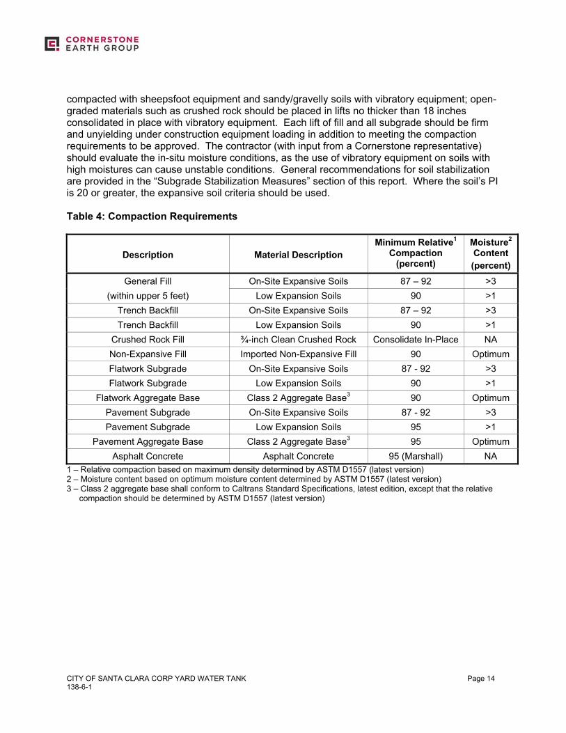
compacted with sheepsfoot equipment and sandy/gravelly soils with vibratory equipment; open-graded materials such as crushed rock should be placed in lifts no thicker than 18 inches consolidated in place with vibratory equipment. Each lift of fill and all subgrade should be firm and unyielding under construction equipment loading in addition to meeting the compaction requirements to be approved. The contractor (with input from a Cornerstone representative) should evaluate the in-situ moisture conditions, as the use of vibratory equipment on soils with high moistures can cause unstable conditions. General recommendations for soil stabilization are provided in the “Subgrade Stabilization Measures” section of this report. Where the soil’s PI is 20 or greater, the expansive soil criteria should be used. Table 4: Compaction Requirements
Description
Material Description
Minimum Relative1 Compaction
(percent)
Moisture2 Content (percent)
General Fill On-Site Expansive Soils 87 – 92 >3 (within upper 5 feet) Low Expansion Soils 90 >1
Trench Backfill On-Site Expansive Soils 87 – 92 >3 Trench Backfill Low Expansion Soils 90 >1
Crushed Rock Fill ¾-inch Clean Crushed Rock Consolidate In-Place NA Non-Expansive Fill Imported Non-Expansive Fill 90 Optimum Flatwork Subgrade On-Site Expansive Soils 87 - 92 >3 Flatwork Subgrade Low Expansion Soils 90 >1
Flatwork Aggregate Base Class 2 Aggregate Base3 90 Optimum Pavement Subgrade On-Site Expansive Soils 87 - 92 >3 Pavement Subgrade Low Expansion Soils 95 >1
Pavement Aggregate Base Class 2 Aggregate Base3 95 Optimum Asphalt Concrete Asphalt Concrete 95 (Marshall) NA
1 – Relative compaction based on maximum density determined by ASTM D1557 (latest version) 2 – Moisture content based on optimum moisture content determined by ASTM D1557 (latest version) 3 – Class 2 aggregate base shall conform to Caltrans Standard Specifications, latest edition, except that the relative
compaction should be determined by ASTM D1557 (latest version)
CITY OF SANTA CLARA CORP YARD WATER TANK 138-6-1
Page 15
6.7.1 Construction Moisture Conditioning Expansive soils can undergo significant volume change when dried then wetted. The contractor should keep all exposed expansive soil subgrade (and also trench excavation side walls) moist until protected by overlying improvements (or trenches are backfilled). If expansive soils are allowed to dry out significantly, re-moisture conditioning may require several days of re-wetting (flooding is not recommended), or deep scarification, moisture conditioning, and re-compaction. 6.8 TRENCH BACKFILL Utility lines constructed within public right-of-way should be trenched, bedded and shaded, and backfilled in accordance with the local or governing jurisdictional requirements. Utility lines in private improvement areas should be constructed in accordance with the following requirements unless superseded by other governing requirements. All utility lines should be bedded and shaded to at least 6 inches over the top of the lines with crushed rock (⅜-inch-diameter or greater) or well-graded sand and gravel materials conforming to the pipe manufacturer’s requirements. Open-graded shading materials should be consolidated in place with vibratory equipment and well-graded materials should be compacted to at least 90 percent relative compaction with vibratory equipment prior to placing subsequent backfill materials. General backfill over shading materials may consist of on-site native materials provided they meet the requirements in the “Material for Fill” section, and are moisture conditioned and compacted in accordance with the requirements in the “Compaction” section. Where utility lines will cross perpendicular to strip footings, the footing should be deepened to encase the utility line, providing sleeves or flexible cushions to protect the pipes from anticipated foundation settlement, or the utility lines should be backfilled to the bottom of footing with sand-cement slurry or lean concrete. Where utility lines will parallel footings and will extend below the “foundation plane of influence,” an imaginary 1:1 plane projected down from the bottom edge of the footing, either the footing will need to be deepened so that the pipe is above the foundation plane of influence or the utility trench will need to be backfilled with sand-cement slurry or lean concrete within the influence zone. Sand-cement slurry used within foundation influence zones should have a minimum compressive strength of 75 psi. 6.9 SITE DRAINAGE Ponding should not be allowed adjacent to building foundations, slabs-on-grade, or pavements. Hardscape surfaces should slope at least 2 percent towards suitable discharge facilities; landscape areas should slope at least 3 percent towards suitable discharge facilities. Roof runoff should be directed away from building areas in closed conduits, to approved infiltration facilities, or on to hardscaped surfaces that drain to suitable facilities. Retention, detention or infiltration facilities should be spaced at least 10 feet from buildings, and preferably at least 5 feet from slabs-on-grade or pavements. However, if retention, detention or infiltration facilities
CITY OF SANTA CLARA CORP YARD WATER TANK 138-6-1
Page 16
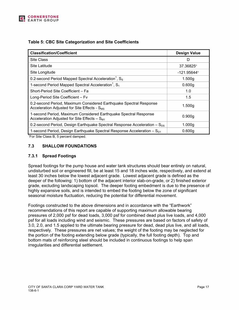
are located within these zones, we recommend that these treatment facilities meet the requirements in the Storm Water Treatment Design Considerations section of this report. SECTION 7: FOUNDATIONS 7.1 SUMMARY OF RECOMMENDATIONS In our opinion, the proposed water tank and pump house structures may be supported on shallow foundations provided the recommendations in the “Earthwork” section and the sections below are followed and the estimated total and differential settlement due to static loads and seismic hazards are tolerable. Shallow foundations would likely consist of spread footings or mat foundations. Spread footings for a tank may be a ring-type spread footing foundation; often this foundation type also includes an oiled-sand and rock base beneath the central portion of the tank. Deep foundation recommendations are also presented in this section. 7.2 SEISMIC DESIGN CRITERIA We understand that a welded steel water tank is likely; therefore, the project structural design will likely be based on ANSI/AWWA D100-11. The ground motion hazard analysis in D100-11 has been updated to include the requirements of ASCE 7-05; however, the 2013 California Building Code (CBC) has adopted the more recent ASCE 7-10. Therefore, we anticipate that the project structural design will be based on the 2013 California Building Code (CBC), which provides criteria for the seismic design of structures in Chapter 16. The “Seismic Coefficients” used to design structures are established based on a series of tables and figures addressing different site factors, including the soil profile in the upper 100 feet below grade and mapped spectral acceleration parameters based on distance to the controlling seismic source/fault system. Based on our borings and review of local geology, the site is underlain by deep alluvial soils with typical SPT “N” values between 15 and 50 blows per foot. Therefore, we have classified the site as Soil Classification D. The mapped spectral acceleration parameters SS and S1 were calculated using the USGS computer program Design Maps, based on the site coordinates presented below and the site classification. The table below lists the various factors used to determine the seismic coefficients and other parameters.
CITY OF SANTA CLARA CORP YARD WATER TANK 138-6-1
Page 17
Table 5: CBC Site Categorization and Site Coefficients Classification/Coefficient Design Value Site Class D Site Latitude 37.36825° Site Longitude -121.95644° 0.2-second Period Mapped Spectral Acceleration1, SS 1.500g 1-second Period Mapped Spectral Acceleration1, S1 0.600g Short-Period Site Coefficient – Fa 1.0 Long-Period Site Coefficient – Fv 1.5 0.2-second Period, Maximum Considered Earthquake Spectral Response Acceleration Adjusted for Site Effects - SMS
1.500g
1-second Period, Maximum Considered Earthquake Spectral Response Acceleration Adjusted for Site Effects – SM1
0.900g
0.2-second Period, Design Earthquake Spectral Response Acceleration – SDS 1.000g 1-second Period, Design Earthquake Spectral Response Acceleration – SD1 0.600g
1For Site Class B, 5 percent damped. 7.3 SHALLOW FOUNDATIONS 7.3.1 Spread Footings Spread footings for the pump house and water tank structures should bear entirely on natural, undisturbed soil or engineered fill, be at least 15 and 18 inches wide, respectively, and extend at least 30 inches below the lowest adjacent grade. Lowest adjacent grade is defined as the deeper of the following: 1) bottom of the adjacent interior slab-on-grade, or 2) finished exterior grade, excluding landscaping topsoil. The deeper footing embedment is due to the presence of highly expansive soils, and is intended to embed the footing below the zone of significant seasonal moisture fluctuation, reducing the potential for differential movement. Footings constructed to the above dimensions and in accordance with the “Earthwork” recommendations of this report are capable of supporting maximum allowable bearing pressures of 2,000 psf for dead loads, 3,000 psf for combined dead plus live loads, and 4,000 psf for all loads including wind and seismic. These pressures are based on factors of safety of 3.0, 2.0, and 1.5 applied to the ultimate bearing pressure for dead, dead plus live, and all loads, respectively. These pressures are net values; the weight of the footing may be neglected for the portion of the footing extending below grade (typically, the full footing depth). Top and bottom mats of reinforcing steel should be included in continuous footings to help span irregularities and differential settlement.
CITY OF SANTA CLARA CORP YARD WATER TANK 138-6-1
Page 18
7.3.2 Footing Settlement Structural loads were not provided to us at the time this report was prepared; therefore, we assumed the typical loading in the following table. Table 6: Assumed Structural Loading
Foundation Area Range of Assumed Loads Ring Foundation (Water Tank) 4 to 6 kips per lineal foot
Perimeter Strip Footing (Pump House) 1 kip per lineal foot Based on the above loading and the allowable bearing pressures presented above, we estimate that the total static footing settlement for the pump house will be on the order of ⅓-inch, with less than about ¼-inch of post-construction differential settlement between adjacent foundation elements. For the water tank, settlement will affect the entirety of the tank area. We estimate static settlement to be on the order of 3 inches, with about 1¾-inches of differential settlement. In addition we estimate that differential seismic movement will be on the order of ⅔-inch over a horizontal distance of 30 feet, resulting in a total estimated differential footing movement of ¾-inch between foundation elements for the pump house, and 2½-inches over the tank area. As our footing loads were assumed, we recommend we be retained to review the final footing layout and loading, and verify the settlement estimates above. 7.3.3 Lateral Loading Lateral loads may be resisted by friction between the bottom of footing and the supporting subgrade, and also by passive pressures generated against footing sidewalls. An ultimate frictional resistance of 0.4 applied to the footing dead load, and an ultimate passive pressure based on an equivalent fluid pressure of 400 pcf may be used in design. The structural engineer should apply an appropriate factor of safety (such as 1.5) to the ultimate values above. Where footings are adjacent to landscape areas without hardscape, the upper 12 inches of soil should be neglected when determining passive pressure capacity. 7.3.4 Spread Footing Construction Considerations Where utility lines will cross perpendicular to strip footings, the footing should be deepened to encase the utility line, providing sleeves or flexible cushions to protect the pipes from anticipated foundation settlement, or the utility lines should be backfilled to the bottom of footing with sand-cement slurry or lean concrete. Where utility lines will parallel footings and will extend below the “foundation plane of influence,” an imaginary 1:1 plane projected down from the bottom edge of the footing, either the footing will need to be deepened so that the pipe is above the foundation plane of influence or the utility trench will need to be backfilled with sand-cement slurry or lean concrete within the influence zone. Sand-cement slurry used within foundation influence zones should have a minimum compressive strength of 75 psi.
CITY OF SANTA CLARA CORP YARD WATER TANK 138-6-1
Page 19
Footing excavations should be filled as soon as possible or be kept moist until concrete placement by regular sprinkling to prevent desiccation. A Cornerstone representative should observe all footing excavations prior to placing reinforcing steel and concrete. If there is a significant schedule delay between our initial observation and concrete placement, we may need to re-observe the excavations. 7.3.5 Reinforced Concrete Mat Foundations The water tank may be supported on a mat foundations bearing on natural soil or engineered fill prepared in accordance with the “Earthwork” section of this report, and designed in accordance with the recommendations below. Due to the presence of highly expansive soils at the site, we recommend that the upper 18 inches below mat foundations consist of non-expansive fill. For design, we assumed average areal bearing pressures of 2200 psf for the water tank; we should be forwarded the final structural loading to check our settlement estimates. This bearing pressure is a net value; the weight of the mat may be neglected for the portion of the mat extending below grade. When evaluating wind and seismic conditions, allowable bearing pressures may be increased by one-third. Top and bottom mats of reinforcing steel should be included in the mat to help span irregularities and resist differential settlement. 7.3.6 Mat Foundation Settlement The estimated static settlement for the tank is 3inches over the footprint of the mat. In addition to the estimated differential static settlements of 1½-inches across the mat area for reinforced concrete mats, the mats should be designed to accommodate an estimated seismic differential movement of ⅔-inch across the mat for a total differential settlement of approximately 2¼-inches. 7.3.7 Lateral Loading Lateral loads may be resisted by friction between the bottom of mat foundation and the supporting subgrade, and also by passive pressures generated against deepened mat edges. An ultimate frictional resistance of 0.4 applied to the mat dead load, and an ultimate passive pressure based on an equivalent fluid pressure of 400 pcf may be used in design. The structural engineer should apply an appropriate factor of safety (such as 1.5) to the ultimate values above. The upper 12 inches of soil should be neglected when determining passive pressure capacity. 7.3.8 Mat Foundation Construction Considerations Due to the presence of expansive soils, mat subgrade areas should be kept moist until concrete placement by regular sprinkling to prevent desiccation. If deep drying is allowed to occur, several days of moisture conditioning (flooding of the pads is not recommended) may be required to allow the moisture to re-penetrate the subgrade. If severe drying occurs, reworking and moisture conditioning of the pad may be required. Prior to mat construction, the subgrade should be proof-rolled and visually observed by a Cornerstone representative to confirm stable subgrade conditions. The pad moisture should also be checked at least 24 hours prior to vapor
CITY OF SANTA CLARA CORP YARD WATER TANK 138-6-1
Page 20
barrier or mat reinforcement placement to confirm that the soil has a moisture content of at least 3 percent over optimum in the upper 12 inches. 7.3.9 Mat Modulus of Soil Subgrade Reaction The modulus value of soil subgrade reaction is a model element that represents the response to a specific loading condition, including the magnitude, rate, and shape of loading, given the subsurface conditions at that location. Based on an assumed diameter of 103 feet with contact pressures on the order of 2,200 psf, our analyses indicated a modulus of 10 pci to be appropriate for design. 7.4 DEEP FOUNDATIONS 7.4.1 Driven Piles The proposed water tank may be supported on driven, pre-cast, pre-stressed (PCPS) concrete friction piles. Adjacent pile centers should be spaced at least three diameters apart, otherwise, a reduction for group effects may be required. Grade beams should span between piles in accordance with structural requirements. Conventional mat slab may be used to distribute the load across the piles provided the subgrade soils are prepared in accordance with the “Earthwork” section. 7.4.1.1 Vertical Capacity and Estimated Settlement As no significantly thick or continuous dense sand layer was encountered during our investigation that would provide adequate end bearing support, vertical capacity is based on frictional resistance. We evaluated the allowable vertical capacity for 12- and 14-inch-square concrete piles and presented the results in Figure 4. As shown in Figure 4, we have assumed that the top of pile/bottom of pile cap occurs at 2 feet below existing site grades. The allowable capacities are for dead plus live loads using a factor of safety of 2.0; dead loads should not exceed two-thirds of the allowable capacities. The allowable capacities may be increased by one-third for wind and seismic loads. Uplift loads should not exceed 75 percent of the allowable downward vertical capacity under seismic loading. Gross capacity of the piles should be less than the structural capacity, estimated to be 250 and 344 kips for typical 12- and 14-inch-square PCPS piles, respectively (Sante Fe-Pomery, Inc.) Total settlement of individual piles should not exceed ½-inch to mobilize static capacities and post-construction differential settlement over a horizontal distance of 30 feet should not exceed ½-inch due to static loads. 7.4.1.2 Lateral Capacity Lateral load resistance is developed by the soil’s resistance to pile bending. The magnitude of the shear and bending moment developed within the pile are dependent on the pile stiffness, embedment length, the fixity of the pile into the pile cap (free or fixed-head conditions), the
CITY OF SANTA CLARA CORP YARD WATER TANK 138-6-1
Page 21
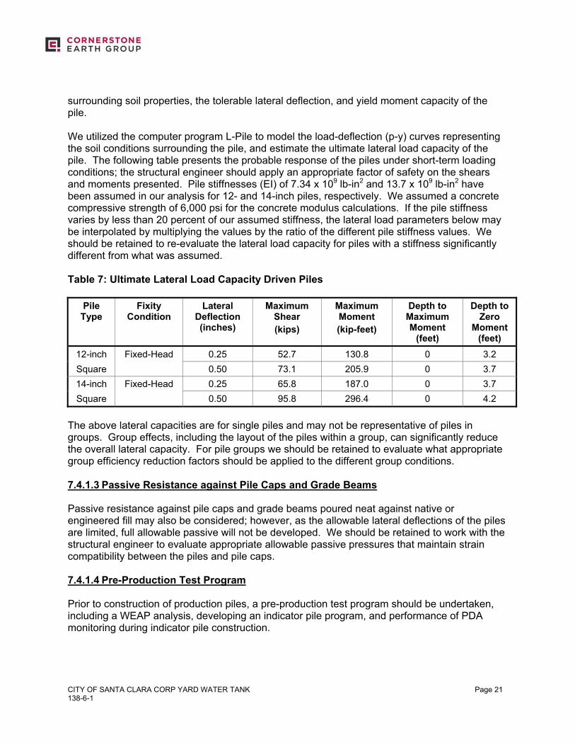
surrounding soil properties, the tolerable lateral deflection, and yield moment capacity of the pile. We utilized the computer program L-Pile to model the load-deflection (p-y) curves representing the soil conditions surrounding the pile, and estimate the ultimate lateral load capacity of the pile. The following table presents the probable response of the piles under short-term loading conditions; the structural engineer should apply an appropriate factor of safety on the shears and moments presented. Pile stiffnesses (EI) of 7.34 x 10⁹ lb-in2 and 13.7 x 10⁹ lb-in2 have been assumed in our analysis for 12- and 14-inch piles, respectively. We assumed a concrete compressive strength of 6,000 psi for the concrete modulus calculations. If the pile stiffness varies by less than 20 percent of our assumed stiffness, the lateral load parameters below may be interpolated by multiplying the values by the ratio of the different pile stiffness values. We should be retained to re-evaluate the lateral load capacity for piles with a stiffness significantly different from what was assumed. Table 7: Ultimate Lateral Load Capacity Driven Piles
Pile Type
Fixity Condition
Lateral Deflection (inches)
Maximum Shear (kips)
Maximum Moment (kip-feet)
Depth to Maximum Moment
(feet)
Depth to Zero
Moment (feet)
12-inch Fixed-Head 0.25 52.7 130.8 0 3.2 Square 0.50 73.1 205.9 0 3.7 14-inch Fixed-Head 0.25 65.8 187.0 0 3.7 Square 0.50 95.8 296.4 0 4.2
The above lateral capacities are for single piles and may not be representative of piles in groups. Group effects, including the layout of the piles within a group, can significantly reduce the overall lateral capacity. For pile groups we should be retained to evaluate what appropriate group efficiency reduction factors should be applied to the different group conditions. 7.4.1.3 Passive Resistance against Pile Caps and Grade Beams Passive resistance against pile caps and grade beams poured neat against native or engineered fill may also be considered; however, as the allowable lateral deflections of the piles are limited, full allowable passive will not be developed. We should be retained to work with the structural engineer to evaluate appropriate allowable passive pressures that maintain strain compatibility between the piles and pile caps. 7.4.1.4 Pre-Production Test Program Prior to construction of production piles, a pre-production test program should be undertaken, including a WEAP analysis, developing an indicator pile program, and performance of PDA monitoring during indicator pile construction.

CITY OF SANTA CLARA CORP YARD WATER TANK 138-6-1
Page 22
7.4.1.4.1 WEAP Analysis We recommend that the pile contractor have a wave equation analysis of piles (WEAP) performed. A WEAP analysis will evaluate the drivability of different pile driving systems taking into consideration the desired pile types, typical pile driving hammers and cushions, and the site soil conditions, especially any relatively thick sand layers. We should be retained to review the WEAP analysis results prior to the start of indicator or production pile construction. 7.4.1.4.2 Indicator Pile Program Due to the variability of the site soil conditions, we recommend that we be retained to review the structural plans and develop an indicator pile program based on the proposed pile locations. This program will target both the areas where the weakest soil conditions were encountered, as well as where sand layers were encountered that are likely to induce high driving stresses within the piles. The indicator pile program will be used to more accurately estimate final pile lengths and determine whether piles can be driven through the sand layers encountered. We recommend that at least 2 indicator piles be installed prior to finalizing pile cast lengths. The indicator piles should be cast to lengths estimated to meet the desired capacity plus an extra 5 feet in case the desired capacity is not met at the design length. It is anticipated that the indicator piles will not be driven to their full length; the contractor should plan on cutting some piles to the desired pile butt elevation. The piles should be driven with the same pile driving equipment/hammers that will be used to drive the production piles. Indicator piles are anticipated to meet or exceed the design capacity and so may be used as production piles; therefore, the indicator piles locations should be surveyed in place. 7.4.1.4.3 PDA Monitoring We also recommend that a pile driving analyzer (PDA) be used during the indicator pile program to evaluate the as-driven pile capacity through dynamic testing. PDA data may indicate that a reduction in production pile lengths is appropriate, providing project cost savings. PDA monitoring should be performed during driving the indicator pile in the weakest soil profile, during driving on all piles selected for re-strikes, and during the re-strikes; piles should be allowed to set up at least seven days prior to re-strike to better define the estimated pile capacity set up curve. PDA monitoring is especially useful during driving piles through significant sand layers to monitor driving stresses and for evaluating pile integrity on any piles suspected of damage. As stand-by costs will be accrued while the pile contractor waits the set-up time for re-strikes, the project structural plans and specifications should clearly indicate the location and number of re-strikes, to avoid unexpected contractor change orders.
CITY OF SANTA CLARA CORP YARD WATER TANK 138-6-1
Page 23
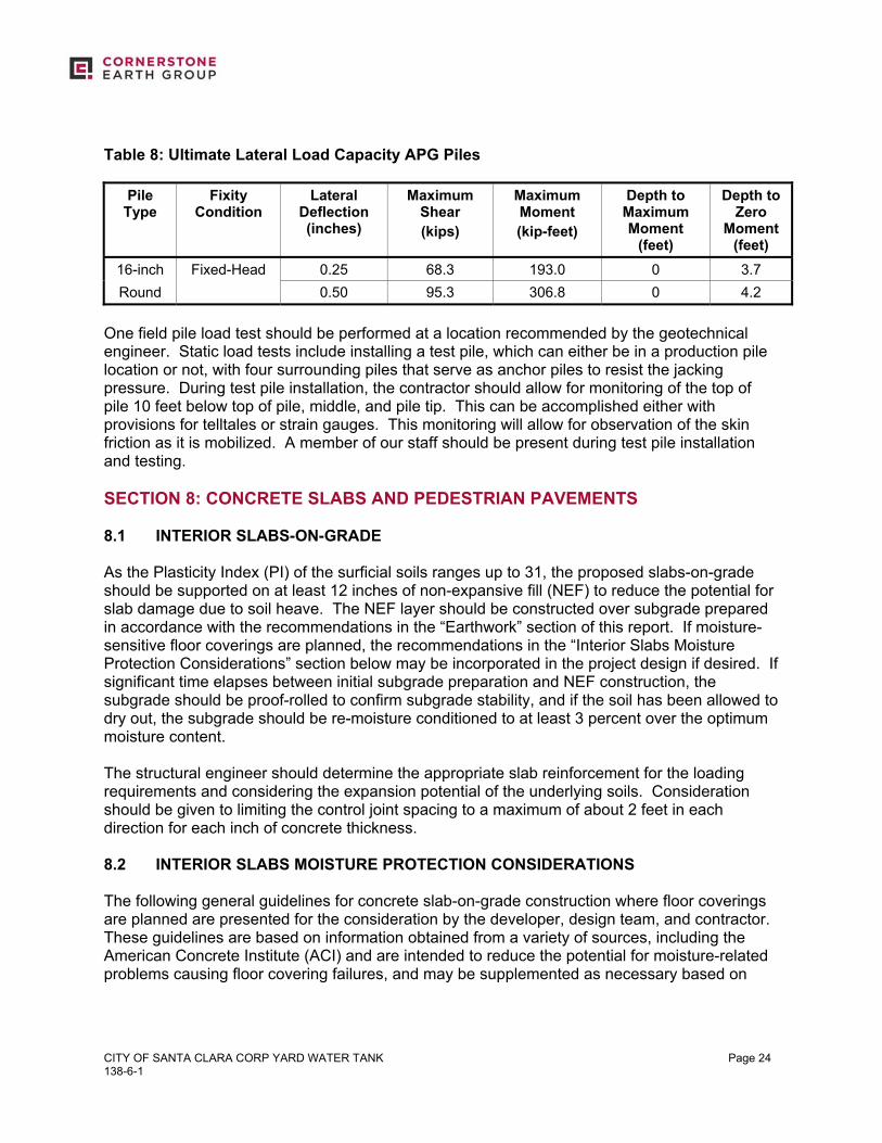
7.4.1.5 Construction Considerations The installation of all indicator and production piles should be observed on a full-time basis by a Cornerstone representative to confirm that the piles are constructed in accordance with our recommendations and project requirements. Since the piles will derive their capacity from skin friction, the production piles should be driven to the design tip elevation. The geotechnical project engineer should review the driving records where any difficult driving and/or refusal conditions are encountered with our field engineer, and evaluate whether there is sufficient tip capacity to allow a length reduction and/or the potential for pile damage. We may recommend performing PDA on any required re-strikes to confirm pile capacity or to evaluate potentially damaged piles during production driving. 7.4.2 Augercast Piles As an alternative to pre-cast driven concrete piles, drilled, cast-in-place displacement augercast piles may be used. Augercast piles are concrete piles that are cast in place using a hollow-stem auger that drills to the design depth and then the sand-cement grout (4,000 to 6,000 psi grout) is pumped through the hollow-stem as the drill stem is extracted. Two types of augercast piles are available: APG piles, which like piers, remove the soil column and replace it with grout; and APGD piles, which displace the soil column as the drill stem is advanced, similar to driven piles, prior to pumping the grout. We anticipate that displacement augercast piles are feasible so that drilling spoils will be minor. Augercast piles are a low noise and vibration installation compared to driven piles. Various types of steel reinforcing, including rebar cages or H-piles may be installed into the still-wet grout after drilling to satisfy bending moment requirements. Vertical and lateral load capacities will be similar to driven piles based on the pile surface area. For example, a 12-inch square pre-cast pile has a similar surface area as a 16-inch round augercast pile, and a 14-inch square pile will be similar to an 18-inch round pile. See Table 8 below for lateral capacities and Figure 5 for the vertical capacities for APG piles. As an alternative, APGD piles will have slightly higher vertical capacities and will have virtually no spoils. We utilized the computer program L-Pile to model the load-deflection (p-y) curves representing the soil conditions surrounding the pile, and estimate the ultimate lateral load capacity of the pile. The following table presents the probable response of the piles under short-term loading conditions; the structural engineer should apply an appropriate factor of safety on the shears and moments presented. Pile stiffness (EI) of 14.2 x 10⁹ lb-in2 have been assumed in our analysis for 16-inch piles, while we assumed a concrete compressive strength of 6,000 psi for the concrete modulus calculations. We should be retained to re-evaluate the lateral load capacity for piles with a stiffness significantly different from what was assumed.
CITY OF SANTA CLARA CORP YARD WATER TANK 138-6-1
Page 24
Table 8: Ultimate Lateral Load Capacity APG Piles
Pile Type
Fixity Condition
Lateral Deflection (inches)
Maximum Shear (kips)
Maximum Moment (kip-feet)
Depth to Maximum Moment
(feet)
Depth to Zero
Moment (feet)
16-inch Fixed-Head 0.25 68.3 193.0 0 3.7 Round 0.50 95.3 306.8 0 4.2
One field pile load test should be performed at a location recommended by the geotechnical engineer. Static load tests include installing a test pile, which can either be in a production pile location or not, with four surrounding piles that serve as anchor piles to resist the jacking pressure. During test pile installation, the contractor should allow for monitoring of the top of pile 10 feet below top of pile, middle, and pile tip. This can be accomplished either with provisions for telltales or strain gauges. This monitoring will allow for observation of the skin friction as it is mobilized. A member of our staff should be present during test pile installation and testing. SECTION 8: CONCRETE SLABS AND PEDESTRIAN PAVEMENTS 8.1 INTERIOR SLABS-ON-GRADE As the Plasticity Index (PI) of the surficial soils ranges up to 31, the proposed slabs-on-grade should be supported on at least 12 inches of non-expansive fill (NEF) to reduce the potential for slab damage due to soil heave. The NEF layer should be constructed over subgrade prepared in accordance with the recommendations in the “Earthwork” section of this report. If moisture-sensitive floor coverings are planned, the recommendations in the “Interior Slabs Moisture Protection Considerations” section below may be incorporated in the project design if desired. If significant time elapses between initial subgrade preparation and NEF construction, the subgrade should be proof-rolled to confirm subgrade stability, and if the soil has been allowed to dry out, the subgrade should be re-moisture conditioned to at least 3 percent over the optimum moisture content. The structural engineer should determine the appropriate slab reinforcement for the loading requirements and considering the expansion potential of the underlying soils. Consideration should be given to limiting the control joint spacing to a maximum of about 2 feet in each direction for each inch of concrete thickness. 8.2 INTERIOR SLABS MOISTURE PROTECTION CONSIDERATIONS The following general guidelines for concrete slab-on-grade construction where floor coverings are planned are presented for the consideration by the developer, design team, and contractor. These guidelines are based on information obtained from a variety of sources, including the American Concrete Institute (ACI) and are intended to reduce the potential for moisture-related problems causing floor covering failures, and may be supplemented as necessary based on
CITY OF SANTA CLARA CORP YARD WATER TANK 138-6-1
Page 25
project-specific requirements. The application of these guidelines or not will not affect the geotechnical aspects of the slab-on-grade performance.
Place a minimum 10-mil vapor retarder conforming to ASTM E 1745, Class C requirements or better directly below the concrete slab; the vapor retarder should extend to the slab edges and be sealed at all seams and penetrations in accordance with manufacturer’s recommendations and ASTM E 1643 requirements. A 4-inch-thick capillary break, consisting of ½- to ¾-inch crushed rock with less than 5 percent passing the No. 200 sieve, should be placed below the vapor retarder and consolidated in place with vibratory equipment. The capillary break rock may be considered as the upper 4 inches of the non-expansive fill previously recommended.
The concrete water:cement ratio should be 0.45 or less. Mid-range plasticizers may be
used to increase concrete workability and facilitate pumping and placement.
Water should not be added after initial batching unless the slump is less than specified and/or the resulting water:cement ratio will not exceed 0.45.
Polishing the concrete surface with metal trowels is not recommended.
Where floor coverings are planned, all concrete surfaces should be properly cured.
Water vapor emission levels and concrete pH should be determined in accordance with
ASTM F1869-98 and F710-98 requirements and evaluated against the floor covering manufacturer’s requirements prior to installation.
8.3 EXTERIOR FLATWORK Exterior concrete flatwork subject to pedestrian and/or occasional light pick up loading should be at least 4 inches thick and supported 6 inches of non-expansive fill overlying subgrade prepared in accordance with the “Earthwork” recommendations of this report. Flatwork that will be subject to heavier or frequent vehicular loading should be designed in accordance with the recommendations in the “Vehicular Pavements” section below. To help reduce the potential for uncontrolled shrinkage cracking, adequate expansion and control joints should be included. Consideration should be given to limiting the control joint spacing to a maximum of about 2 feet in each direction for each inch of concrete thickness. Flatwork should be isolated from adjacent foundations or retaining walls except where limited sections of structural slabs are included to help span irregularities in retaining wall backfill at the transitions between at-grade and on-structure flatwork. SECTION 9: VEHICULAR PAVEMENTS 9.1 ASPHALT CONCRETE The following asphalt concrete pavement recommendations tabulated below are based on the Procedure 608 of the Caltrans Highway Design Manual, estimated traffic indices for various
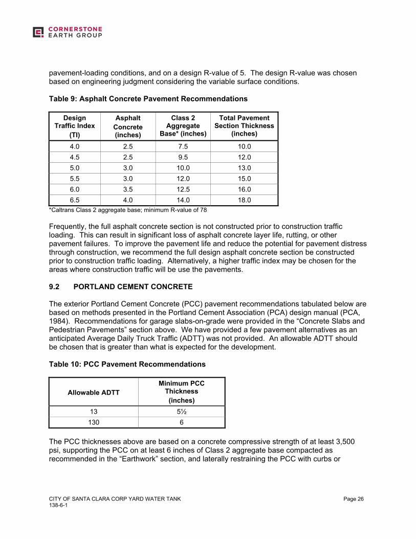
CITY OF SANTA CLARA CORP YARD WATER TANK 138-6-1
Page 26
pavement-loading conditions, and on a design R-value of 5. The design R-value was chosen based on engineering judgment considering the variable surface conditions. Table 9: Asphalt Concrete Pavement Recommendations
Design Traffic Index
(TI)
Asphalt Concrete (inches)
Class 2 Aggregate
Base* (inches)
Total Pavement Section Thickness
(inches)
4.0 2.5 7.5 10.0 4.5 2.5 9.5 12.0 5.0 3.0 10.0 13.0 5.5 3.0 12.0 15.0 6.0 3.5 12.5 16.0 6.5 4.0 14.0 18.0
*Caltrans Class 2 aggregate base; minimum R-value of 78 Frequently, the full asphalt concrete section is not constructed prior to construction traffic loading. This can result in significant loss of asphalt concrete layer life, rutting, or other pavement failures. To improve the pavement life and reduce the potential for pavement distress through construction, we recommend the full design asphalt concrete section be constructed prior to construction traffic loading. Alternatively, a higher traffic index may be chosen for the areas where construction traffic will be use the pavements. 9.2 PORTLAND CEMENT CONCRETE The exterior Portland Cement Concrete (PCC) pavement recommendations tabulated below are based on methods presented in the Portland Cement Association (PCA) design manual (PCA, 1984). Recommendations for garage slabs-on-grade were provided in the “Concrete Slabs and Pedestrian Pavements” section above. We have provided a few pavement alternatives as an anticipated Average Daily Truck Traffic (ADTT) was not provided. An allowable ADTT should be chosen that is greater than what is expected for the development. Table 10: PCC Pavement Recommendations
Allowable ADTT
Minimum PCC Thickness (inches)
13 5½ 130 6
The PCC thicknesses above are based on a concrete compressive strength of at least 3,500 psi, supporting the PCC on at least 6 inches of Class 2 aggregate base compacted as recommended in the “Earthwork” section, and laterally restraining the PCC with curbs or
CITY OF SANTA CLARA CORP YARD WATER TANK 138-6-1
Page 27
concrete shoulders. Adequate expansion and control joints should be included. Consideration should be given to limiting the control joint spacing to a maximum of about 2 feet in each direction for each inch of concrete thickness. Due to the expansive surficial soils present, we recommend that the construction and expansion joints be dowelled. SECTION 10: LIMITATIONS This report, an instrument of professional service, has been prepared for the sole use of GHD specifically to support the design of the City of Santa Clara Corp Yard Water Tank project in Santa Clara, California. The opinions, conclusions, and recommendations presented in this report have been formulated in accordance with accepted geotechnical engineering practices that exist in Northern California at the time this report was prepared. No warranty, expressed or implied, is made or should be inferred. Recommendations in this report are based upon the soil and ground water conditions encountered during our subsurface exploration. If variations or unsuitable conditions are encountered during construction, Cornerstone must be contacted to provide supplemental recommendations, as needed. GHD may have provided Cornerstone with plans, reports and other documents prepared by others. GHD understands that Cornerstone reviewed and relied on the information presented in these documents and cannot be responsible for their accuracy. Cornerstone prepared this report with the understanding that it is the responsibility of the owner or his representatives to see that the recommendations contained in this report are presented to other members of the design team and incorporated into the project plans and specifications, and that appropriate actions are taken to implement the geotechnical recommendations during construction. Conclusions and recommendations presented in this report are valid as of the present time for the development as currently planned. Changes in the condition of the property or adjacent properties may occur with the passage of time, whether by natural processes or the acts of other persons. In addition, changes in applicable or appropriate standards may occur through legislation or the broadening of knowledge. Therefore, the conclusions and recommendations presented in this report may be invalidated, wholly or in part, by changes beyond Cornerstone’s control. This report should be reviewed by Cornerstone after a period of three (3) years has elapsed from the date of this report. In addition, if the current project design is changed, then Cornerstone must review the proposed changes and provide supplemental recommendations, as needed. An electronic transmission of this report may also have been issued. While Cornerstone has taken precautions to produce a complete and secure electronic transmission, please check the electronic transmission against the hard copy version for conformity. Recommendations provided in this report are based on the assumption that Cornerstone will be retained to provide observation and testing services during construction to confirm that
CITY OF SANTA CLARA CORP YARD WATER TANK 138-6-1
Page 28
conditions are similar to that assumed for design, and to form an opinion as to whether the work has been performed in accordance with the project plans and specifications. If we are not retained for these services, Cornerstone cannot assume any responsibility for any potential claims that may arise during or after construction as a result of misuse or misinterpretation of Cornerstone’s report by others. Furthermore, Cornerstone will cease to be the Geotechnical-Engineer-of-Record if we are not retained for these services. SECTION 11: REFERENCES Association of Bay Area Governments (ABAG), 2005, Dam Innudation Map: http://www.abag.ca.gov/bayarea/eqmaps/dfpickc.html Boulanger, R.W. and Idriss, I.M., 2004, Evaluating the Potential for Liquefaction or Cyclic Failure of Silts and Clays, Department of Civil & Environmental Engineering, College of Engineering, University of California at Davis. California Building Code, 2013, Structural Engineering Design Provisions, Vol. 2. California Department of Conservation Division of Mines and Geology, 1998, Maps of Known Active Fault Near-Source Zones in California and Adjacent Portions of Nevada, International Conference of Building Officials, February, 1998. California Division of Mines and Geology (2008), “Guidelines for Evaluating and Mitigating Seismic Hazards in California, Special Publication 117A, September. California Geological Survey, 2003, State of California Seismic Hazard Zones, San Jose West 7.5-Minute Quadrangle, California: Seismic Hazard Zone Report 091. Federal Emergency Management Administration (FEMA), 2009, FIRM City of Santa Clara California, Community Panel #06085C0227H. Idriss, I.M., and Boulanger, R.W., 2008, Soil Liquefaction During Earthquakes, Earthquake Engineering Research Institute, Oakland, CA, 237 p. Portland Cement Association, 1984, Thickness Design for Concrete Highway and Street Pavements: report. Rogers, T.H., and J.W. Williams, 1974 Potential Seismic Hazards in Santa Clara County, California, Special Report No. 107: California Division of Mines and Geology. Seed, H.B. and I.M. Idriss, 1982, Ground Motions and Soil Liquefaction During Earthquakes: Earthquake Engineering Research Institute. State of California Department of Transportation, 2006, Highway Design Manual, Latest Edition.
CITY OF SANTA CLARA CORP YARD WATER TANK 138-6-1
Page 29
USGS, 2013, U.S. Seismic Design Maps, revision date April 2, 2013 - A Computer Program for determining mapped ground motion parameters for use with IBC available at http://geohazards.usgs.gov/designmaps/us/application.php. Working Group on California Earthquake Probabilities, 2007, The Uniform Earthquake Rupture Forecast, Version 2 (UCRF 2), U.S.G.S. Open File Report 2007-1437. Youd, T.L. and C.T. Garris, 1995, Liquefaction-Induced Ground-Surface Disruption: Journal of Geotechnical Engineering, Vol. 121, No. 11, pp. 805 - 809. Youd, T.L. and Idriss, I.M., et al, 1997, Proceedings of the NCEER Workshop on Evaluation of Liquefaction Resistance of Soils: National Center for Earthquake Engineering Research, Technical Report NCEER - 97-0022, January 5, 6, 1996.
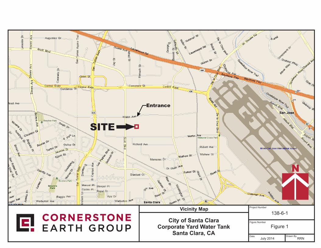
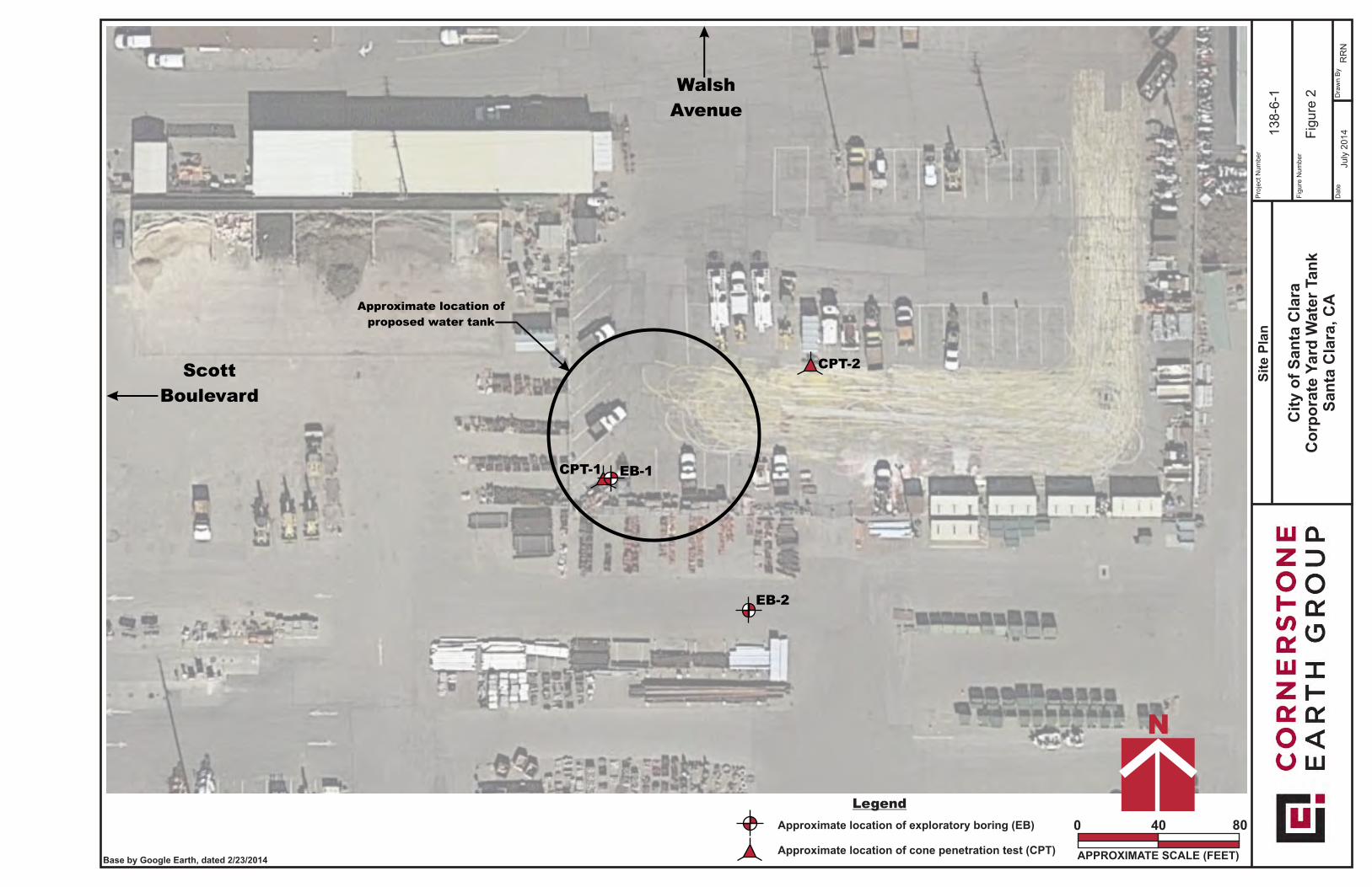
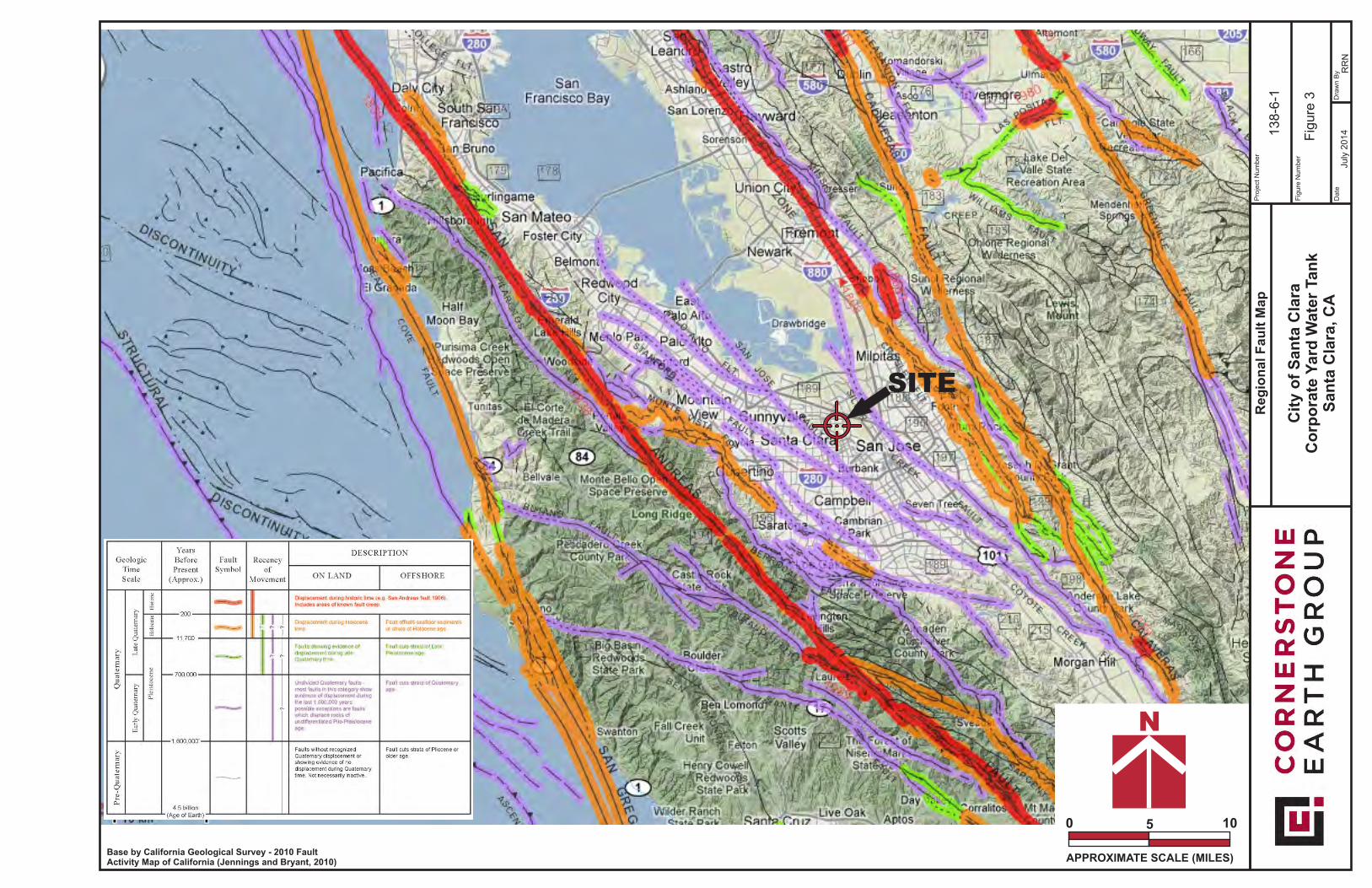
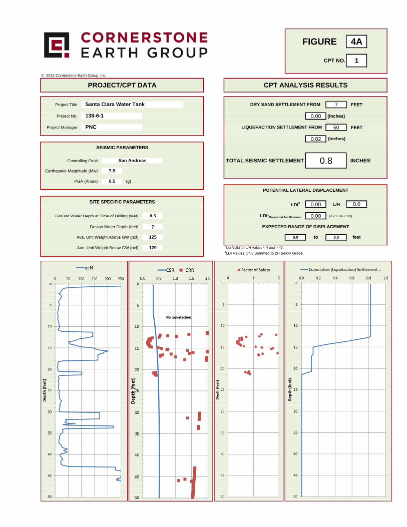
4AFIGURE 4AFIGURE
1CPT NO. 1
© 2012 Cornerstone Earth Group, Inc.
PROJECT/CPT DATA CPT ANALYSIS RESULTSPROJECT/CPT DATA CPT ANALYSIS RESULTS
Project Title 7 FEETSanta Clara Water Tank DRY SAND SETTLEMENT FROMj
Project No. 0.00 (Inches)138-6-1j 0.00 ( )
Project Manager 50 FEETPNC LIQUEFACTION SETTLEMENT FROMj g 50 FEETC Q
0 82 (Inches)0.82 (Inches)
S S C SSEISMIC PARAMETERS
Controlling Fault San Andreas TOTAL SEISMIC SETTLEMENT 0 8 INCHESCo t o g au t TOTAL SEISMIC SETTLEMENT 0.8 INCHES
Earthquake Magnitude (Mw) 7.9q g ( )
PGA (Amax) 0.5 (g)
POTENTIAL LATERAL DISPLACEMENTPOTENTIAL LATERAL DISPLACEMENT
SITE SPECIFIC PARAMETERS LDI2 0.00 L/H 0.0SITE SPECIFIC PARAMETERS
Ground Water Depth at Time of Drilling (feet) 8.5 LDI1Corrected for Distance 0.00 (4 < L/H < 40)p g ( ) Corrected for Distance 0.00 ( )
Design Water Depth (feet) 7 EXPECTED RANGE OF DISPLACEMENTg p ( )
Ave. Unit Weight Above GW (pcf) 125 0.0 to 0.0 feet
Ave. Unit Weight Below GW (pcf) 120 1Not Valid for L/H Values < 4 and > 40.2LDI Values Only Summed to 2H Below Grade.
qcN Cumulative (Liquefaction) Settlement …Factor of SafetyqcN CSR CRR0 0 0 2 0 4 0 6 0 8 1 00 1 20 50 100 150 200 250 0 0 0 5 1 0 1 5 2 0
00.0 0.2 0.4 0.6 0.8 1.0
00 1 2
00 50 100 150 200 250
00.0 0.5 1.0 1.5 2.0
00 0
555 55 5
No LiquefactionNo Liquefaction
101010 10
151515 15
2020 202020 20
)
eet)
et)et) et)
25(fe25(fee(fee
(fe 25
pth 25
pth 25
pth 25th
DepDep
Dep ept
DD De
303030 30 303030 30
353535 35 353535 35
404040 4040
454545 4545
505050 50
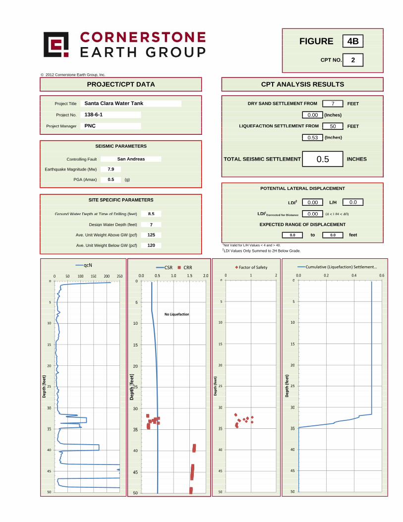
4BFIGURE 4BFIGURE
2CPT NO. 2
© 2012 Cornerstone Earth Group, Inc.
PROJECT/CPT DATA CPT ANALYSIS RESULTSPROJECT/CPT DATA CPT ANALYSIS RESULTS
Project Title 7 FEETDRY SAND SETTLEMENT FROMSanta Clara Water Tankj
Project No. 0.00 (Inches)138-6-1j 0.00 ( )
Project Manager 50 FEETPNC LIQUEFACTION SETTLEMENT FROMj g 50 FEETC Q
0 53 (Inches)0.53 (Inches)
S S C SSEISMIC PARAMETERS
Controlling Fault TOTAL SEISMIC SETTLEMENT 0 5 INCHESSan AndreasCo t o g au t TOTAL SEISMIC SETTLEMENT 0.5 INCHES
Earthquake Magnitude (Mw) 7.9q g ( )
PGA (Amax) 0.5 (g)
POTENTIAL LATERAL DISPLACEMENTPOTENTIAL LATERAL DISPLACEMENT
SITE SPECIFIC PARAMETERS LDI2 0.00 L/H 0.0SITE SPECIFIC PARAMETERS
Ground Water Depth at Time of Drilling (feet) 8.5 LDI1Corrected for Distance 0.00 (4 < L/H < 40)p g ( ) Corrected for Distance 0.00 ( )
Design Water Depth (feet) 7 EXPECTED RANGE OF DISPLACEMENTg p ( )
Ave. Unit Weight Above GW (pcf) 125 0.0 to 0.0 feet
Ave. Unit Weight Below GW (pcf) 120 1Not Valid for L/H Values < 4 and > 40.2LDI Values Only Summed to 2H Below Grade.
qcN Cumulative (Liquefaction) Settlement …Factor of SafetyqcN CSR CRR0 0 0 2 0 4 0 60 1 20 50 100 150 200 250 0 0 0 5 1 0 1 5 2 0
00.0 0.2 0.4 0.6
00 1 2
00 50 100 150 200 250
00.0 0.5 1.0 1.5 2.0
00 0
555 55 5
No LiquefactionNo Liquefaction
101010 10
151515 15
2020 202020 20
)
eet)
et)et) et)
25(fe25(fee(fee
(fe 25
pth 25
pth 25
pth 25th
DepDep
Dep ept
DD De
303030 30 303030 30
353535 35 353535 35
404040 4040
454545 4545
505050 50
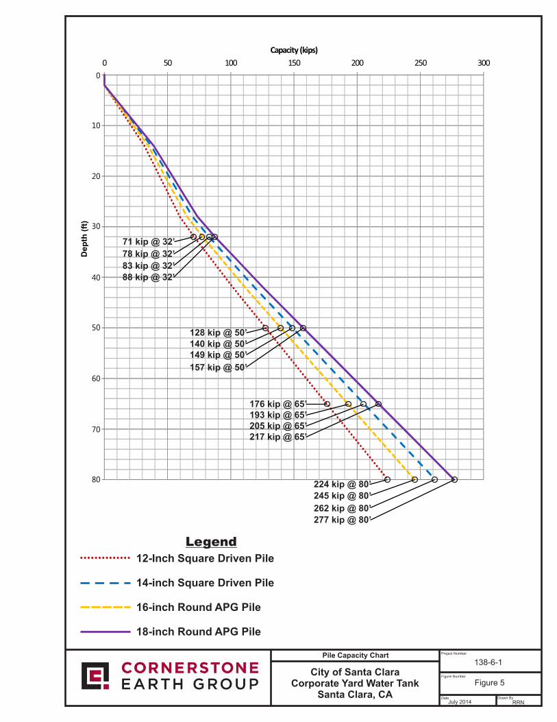
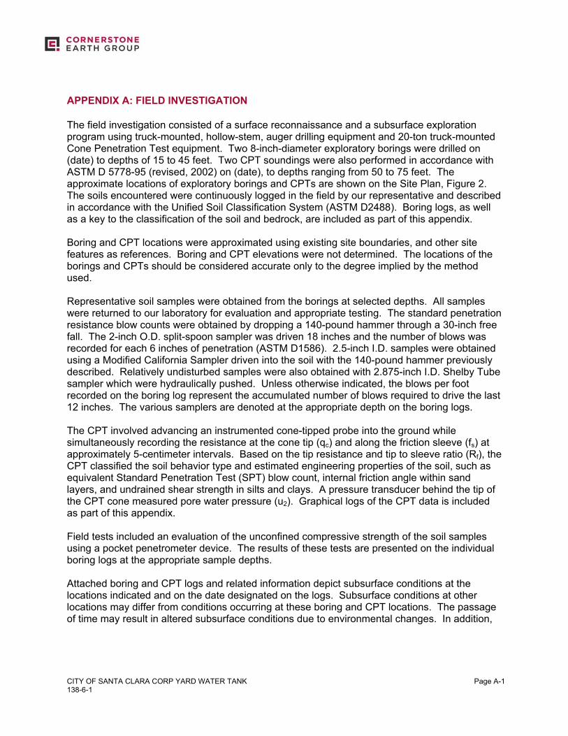
CITY OF SANTA CLARA CORP YARD WATER TANK 138-6-1
Page A-1
APPENDIX A: FIELD INVESTIGATION The field investigation consisted of a surface reconnaissance and a subsurface exploration program using truck-mounted, hollow-stem, auger drilling equipment and 20-ton truck-mounted Cone Penetration Test equipment. Two 8-inch-diameter exploratory borings were drilled on (date) to depths of 15 to 45 feet. Two CPT soundings were also performed in accordance with ASTM D 5778-95 (revised, 2002) on (date), to depths ranging from 50 to 75 feet. The approximate locations of exploratory borings and CPTs are shown on the Site Plan, Figure 2. The soils encountered were continuously logged in the field by our representative and described in accordance with the Unified Soil Classification System (ASTM D2488). Boring logs, as well as a key to the classification of the soil and bedrock, are included as part of this appendix. Boring and CPT locations were approximated using existing site boundaries, and other site features as references. Boring and CPT elevations were not determined. The locations of the borings and CPTs should be considered accurate only to the degree implied by the method used. Representative soil samples were obtained from the borings at selected depths. All samples were returned to our laboratory for evaluation and appropriate testing. The standard penetration resistance blow counts were obtained by dropping a 140-pound hammer through a 30-inch free fall. The 2-inch O.D. split-spoon sampler was driven 18 inches and the number of blows was recorded for each 6 inches of penetration (ASTM D1586). 2.5-inch I.D. samples were obtained using a Modified California Sampler driven into the soil with the 140-pound hammer previously described. Relatively undisturbed samples were also obtained with 2.875-inch I.D. Shelby Tube sampler which were hydraulically pushed. Unless otherwise indicated, the blows per foot recorded on the boring log represent the accumulated number of blows required to drive the last 12 inches. The various samplers are denoted at the appropriate depth on the boring logs. The CPT involved advancing an instrumented cone-tipped probe into the ground while simultaneously recording the resistance at the cone tip (qc) and along the friction sleeve (fs) at approximately 5-centimeter intervals. Based on the tip resistance and tip to sleeve ratio (Rf), the CPT classified the soil behavior type and estimated engineering properties of the soil, such as equivalent Standard Penetration Test (SPT) blow count, internal friction angle within sand layers, and undrained shear strength in silts and clays. A pressure transducer behind the tip of the CPT cone measured pore water pressure (u2). Graphical logs of the CPT data is included as part of this appendix. Field tests included an evaluation of the unconfined compressive strength of the soil samples using a pocket penetrometer device. The results of these tests are presented on the individual boring logs at the appropriate sample depths. Attached boring and CPT logs and related information depict subsurface conditions at the locations indicated and on the date designated on the logs. Subsurface conditions at other locations may differ from conditions occurring at these boring and CPT locations. The passage of time may result in altered subsurface conditions due to environmental changes. In addition,
CITY OF SANTA CLARA CORP YARD WATER TANK 138-6-1
Page A-2
any stratification lines on the logs represent the approximate boundary between soil types and the transition may be gradual.
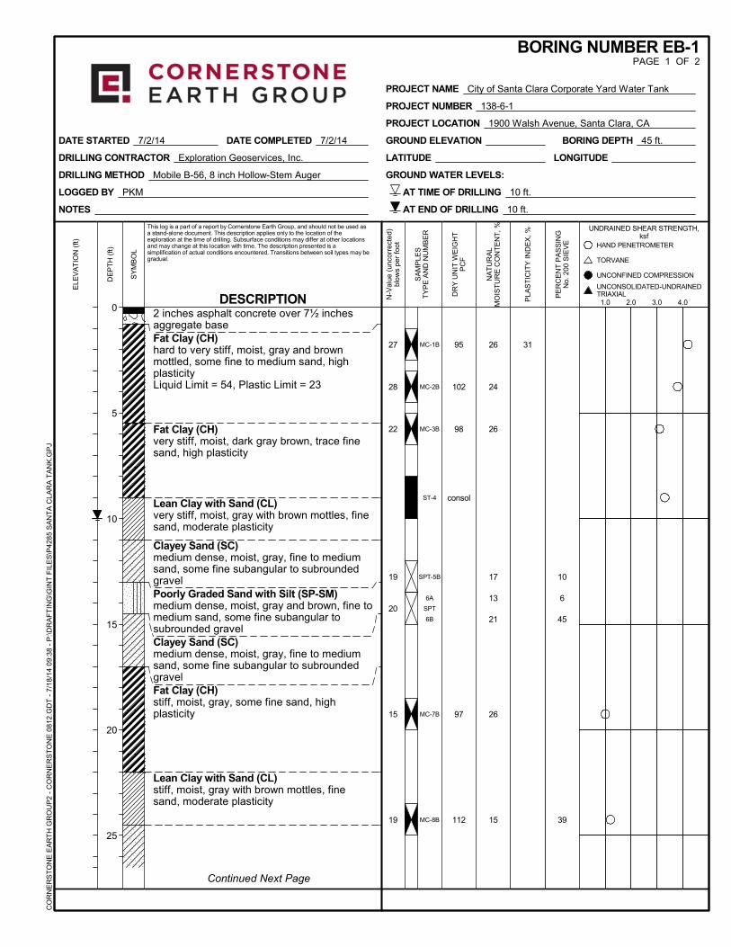
10
6
45
39
2 inches asphalt concrete over 7½ inchesaggregate baseFat Clay (CH)hard to very stiff, moist, gray and brownmottled, some fine to medium sand, highplasticityLiquid Limit = 54, Plastic Limit = 23
Fat Clay (CH)very stiff, moist, dark gray brown, trace finesand, high plasticity
Lean Clay with Sand (CL)very stiff, moist, gray with brown mottles, finesand, moderate plasticity
Clayey Sand (SC)medium dense, moist, gray, fine to mediumsand, some fine subangular to subroundedgravelPoorly Graded Sand with Silt (SP-SM)medium dense, moist, gray and brown, fine tomedium sand, some fine subangular tosubrounded gravelClayey Sand (SC)medium dense, moist, gray, fine to mediumsand, some fine subangular to subroundedgravelFat Clay (CH)stiff, moist, gray, some fine sand, highplasticity
Lean Clay with Sand (CL)stiff, moist, gray with brown mottles, finesand, moderate plasticity
MC-1B
MC-2B
MC-3B
ST-4
SPT-5B
6A
SPT
6B
MC-7B
MC-8B
26
24
26
17
13
21
26
15
95
102
98
consol
97
112
3127
28
22
19
20
15
19
NOTES
LOGGED BY PKM
DRILLING METHOD Mobile B-56, 8 inch Hollow-Stem Auger
DRILLING CONTRACTOR Exploration Geoservices, Inc.
GROUND WATER LEVELS:
DATE STARTED 7/2/14 DATE COMPLETED 7/2/14 BORING DEPTH 45 ft.GROUND ELEVATION
LATITUDE LONGITUDE
AT TIME OF DRILLING 10 ft.
AT END OF DRILLING 10 ft.
UNCONFINED COMPRESSION
PE
RC
EN
T P
AS
SIN
GN
o. 2
00 S
IEV
E
SY
MB
OL
Continued Next Page
ELE
VA
TIO
N (
ft)
PROJECT NAME City of Santa Clara Corporate Yard Water Tank
PROJECT NUMBER 138-6-1
PROJECT LOCATION 1900 Walsh Avenue, Santa Clara, CA
BORING NUMBER EB-1PAGE 1 OF 2
This log is a part of a report by Cornerstone Earth Group, and should not be used asa stand-alone document. This description applies only to the location of theexploration at the time of drilling. Subsurface conditions may differ at other locationsand may change at this location with time. The description presented is asimplification of actual conditions encountered. Transitions between soil types may begradual.
DESCRIPTION
UNDRAINED SHEAR STRENGTH,ksf
SA
MP
LES
TY
PE
AN
D N
UM
BE
R
DE
PT
H (
ft)
0
5
10
15
20
25
NA
TU
RA
LM
OIS
TU
RE
CO
NT
EN
T,
%
DR
Y U
NIT
WE
IGH
TP
CF
PLA
ST
ICIT
Y IN
DE
X, %
TORVANE
1.0 2.0 3.0 4.0
HAND PENETROMETER
N-V
alue
(un
corr
ecte
d)bl
ows
per
foot
CO
RN
ER
ST
ON
E E
AR
TH
GR
OU
P2
- C
OR
NE
RS
TO
NE
081
2.G
DT
- 7
/18
/14
09:
38 -
P:\D
RA
FT
ING
\GIN
T F
ILE
S\P
4285
SA
NT
A C
LAR
A T
AN
K.G
PJ
UNCONSOLIDATED-UNDRAINEDTRIAXIAL
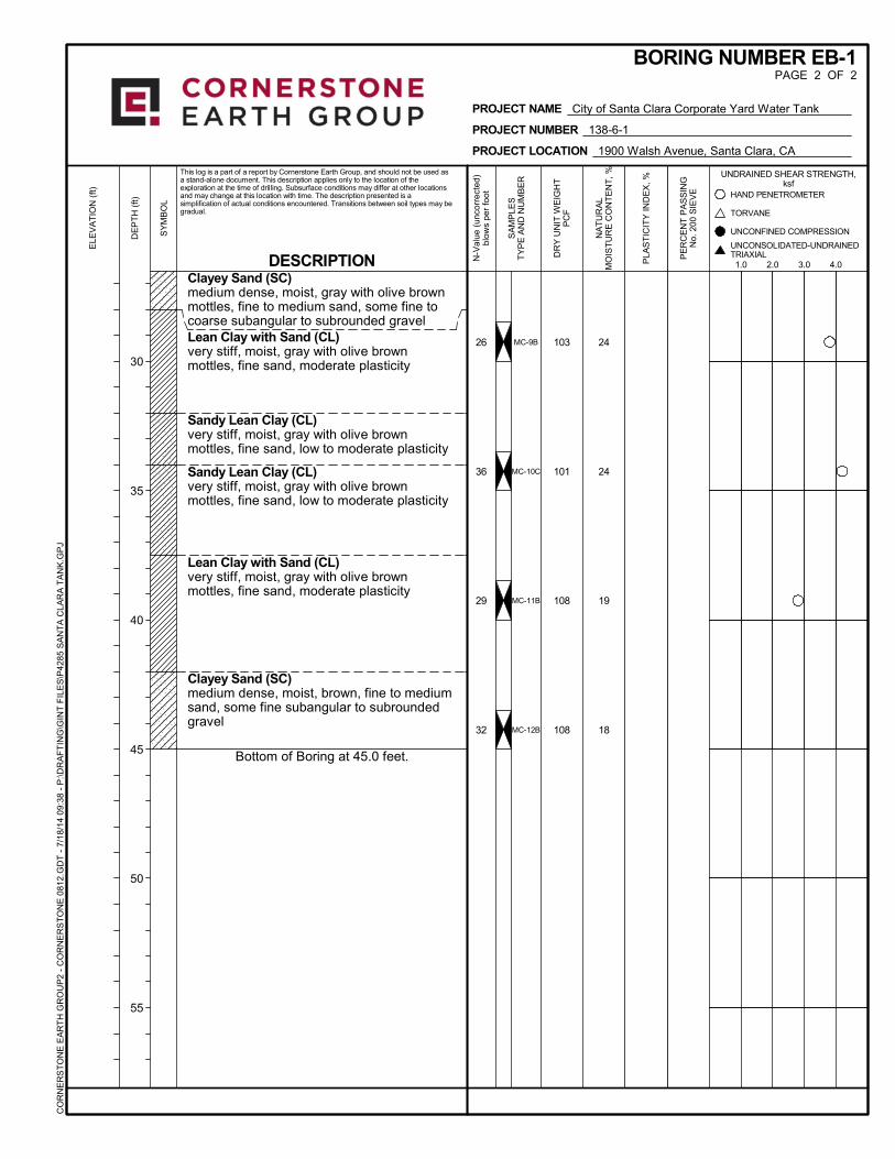
Clayey Sand (SC)medium dense, moist, gray with olive brownmottles, fine to medium sand, some fine tocoarse subangular to subrounded gravelLean Clay with Sand (CL)very stiff, moist, gray with olive brownmottles, fine sand, moderate plasticity
Sandy Lean Clay (CL)very stiff, moist, gray with olive brownmottles, fine sand, low to moderate plasticity
Sandy Lean Clay (CL)very stiff, moist, gray with olive brownmottles, fine sand, low to moderate plasticity
Lean Clay with Sand (CL)very stiff, moist, gray with olive brownmottles, fine sand, moderate plasticity
Clayey Sand (SC)medium dense, moist, brown, fine to mediumsand, some fine subangular to subroundedgravel
Bottom of Boring at 45.0 feet.
MC-9B
MC-10C
MC-11B
MC-12B
24
24
19
18
103
101
108
108
26
36
29
32
UNCONFINED COMPRESSION
PE
RC
EN
T P
AS
SIN
GN
o. 2
00 S
IEV
E
SY
MB
OL
ELE
VA
TIO
N (
ft)
PROJECT NAME City of Santa Clara Corporate Yard Water Tank
PROJECT NUMBER 138-6-1
PROJECT LOCATION 1900 Walsh Avenue, Santa Clara, CA
BORING NUMBER EB-1PAGE 2 OF 2
This log is a part of a report by Cornerstone Earth Group, and should not be used asa stand-alone document. This description applies only to the location of theexploration at the time of drilling. Subsurface conditions may differ at other locationsand may change at this location with time. The description presented is asimplification of actual conditions encountered. Transitions between soil types may begradual.
DESCRIPTION
UNDRAINED SHEAR STRENGTH,ksf
SA
MP
LES
TY
PE
AN
D N
UM
BE
R
DE
PT
H (
ft)
30
35
40
45
50
55
NA
TU
RA
LM
OIS
TU
RE
CO
NT
EN
T,
%
DR
Y U
NIT
WE
IGH
TP
CF
PLA
ST
ICIT
Y IN
DE
X, %
TORVANE
1.0 2.0 3.0 4.0
HAND PENETROMETER
N-V
alue
(un
corr
ecte
d)bl
ows
per
foot
CO
RN
ER
ST
ON
E E
AR
TH
GR
OU
P2
- C
OR
NE
RS
TO
NE
081
2.G
DT
- 7
/18
/14
09:
38 -
P:\D
RA
FT
ING
\GIN
T F
ILE
S\P
4285
SA
NT
A C
LAR
A T
AN
K.G
PJ
UNCONSOLIDATED-UNDRAINEDTRIAXIAL
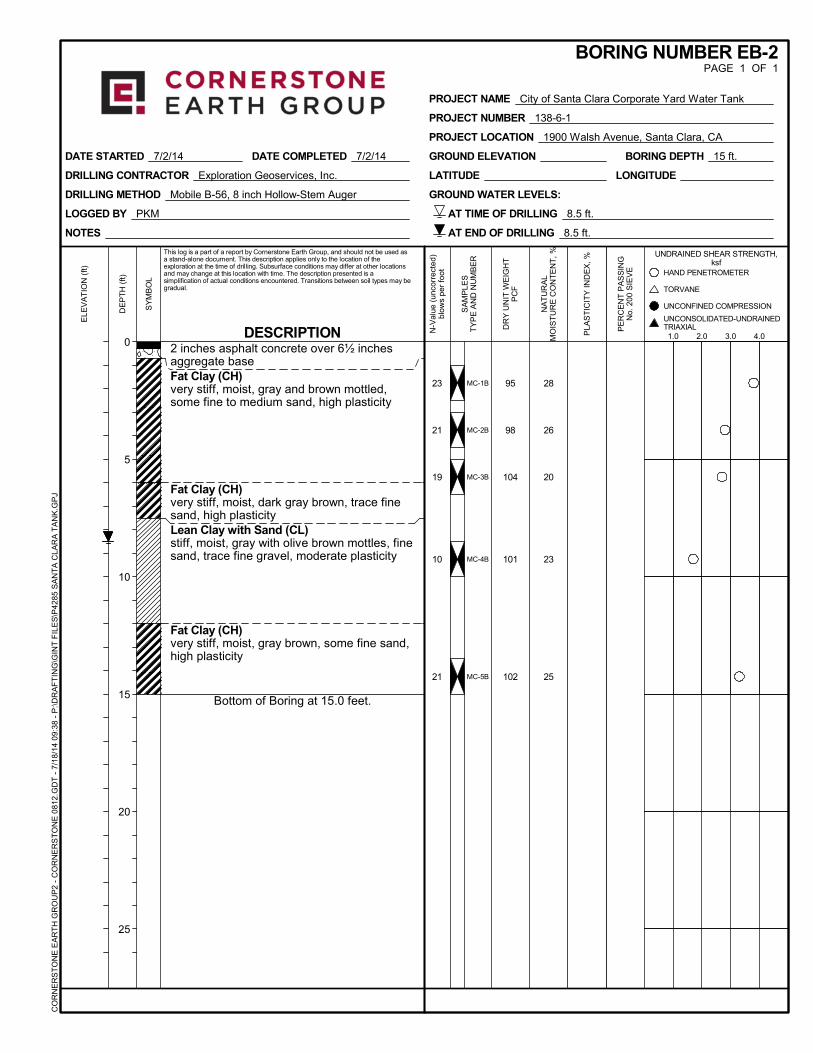
2 inches asphalt concrete over 6½ inchesaggregate baseFat Clay (CH)very stiff, moist, gray and brown mottled,some fine to medium sand, high plasticity
Fat Clay (CH)very stiff, moist, dark gray brown, trace finesand, high plasticityLean Clay with Sand (CL)stiff, moist, gray with olive brown mottles, finesand, trace fine gravel, moderate plasticity
Fat Clay (CH)very stiff, moist, gray brown, some fine sand,high plasticity
Bottom of Boring at 15.0 feet.
MC-1B
MC-2B
MC-3B
MC-4B
MC-5B
28
26
20
23
25
95
98
104
101
102
23
21
19
10
21
NOTES
LOGGED BY PKM
DRILLING METHOD Mobile B-56, 8 inch Hollow-Stem Auger
DRILLING CONTRACTOR Exploration Geoservices, Inc.
GROUND WATER LEVELS:
DATE STARTED 7/2/14 DATE COMPLETED 7/2/14 BORING DEPTH 15 ft.GROUND ELEVATION
LATITUDE LONGITUDE
AT TIME OF DRILLING 8.5 ft.
AT END OF DRILLING 8.5 ft.
UNCONFINED COMPRESSION
PE
RC
EN
T P
AS
SIN
GN
o. 2
00 S
IEV
E
SY
MB
OL
ELE
VA
TIO
N (
ft)
PROJECT NAME City of Santa Clara Corporate Yard Water Tank
PROJECT NUMBER 138-6-1
PROJECT LOCATION 1900 Walsh Avenue, Santa Clara, CA
BORING NUMBER EB-2PAGE 1 OF 1
This log is a part of a report by Cornerstone Earth Group, and should not be used asa stand-alone document. This description applies only to the location of theexploration at the time of drilling. Subsurface conditions may differ at other locationsand may change at this location with time. The description presented is asimplification of actual conditions encountered. Transitions between soil types may begradual.
DESCRIPTION
UNDRAINED SHEAR STRENGTH,ksf
SA
MP
LES
TY
PE
AN
D N
UM
BE
R
DE
PT
H (
ft)
0
5
10
15
20
25
NA
TU
RA
LM
OIS
TU
RE
CO
NT
EN
T,
%
DR
Y U
NIT
WE
IGH
TP
CF
PLA
ST
ICIT
Y IN
DE
X, %
TORVANE
1.0 2.0 3.0 4.0
HAND PENETROMETER
N-V
alue
(un
corr
ecte
d)bl
ows
per
foot
CO
RN
ER
ST
ON
E E
AR
TH
GR
OU
P2
- C
OR
NE
RS
TO
NE
081
2.G
DT
- 7
/18
/14
09:
38 -
P:\D
RA
FT
ING
\GIN
T F
ILE
S\P
4285
SA
NT
A C
LAR
A T
AN
K.G
PJ
UNCONSOLIDATED-UNDRAINEDTRIAXIAL
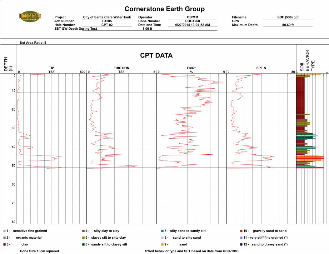
Cornerstone Earth GroupProject City of Santa Clara Water Tank Operator CB/MM Filename SDF (536).cptJob Number P4285 Cone Number DDG1268 GPSHole Number CPT-02 Date and Time 6/27/2014 10:04:52 AM Maximum Depth 50.69 ftEST GW Depth During Test 8.00 ft
Net Area Ratio .8
Cone Size 10cm squared Soil Behavior Referance*Soil behavior type and SPT based on data from UBC-1983
0
10
20
30
40
50
60
70
80
0 500 TIPTSF 0 5
FRICTIONTSF 0 9
Fs/Qt% 0 80
SPT N0 12
1 - sensitive fine grained
2 - organic material
3 - clay
4 - silty clay to clay
5 - clayey silt to silty clay
6 - sandy silt to clayey silt
7 - silty sand to sandy silt
8 - sand to silty sand
9 - sand
10 - gravelly sand to sand
11 - very stiff fine grained (*)
12 - sand to clayey sand (*)
CPT DATA
DEP
TH(ft)
SOIL
BEHAV
IOR
TYPE
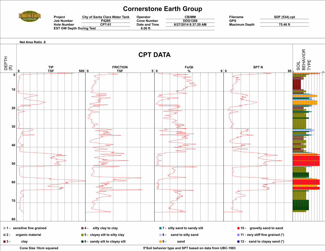
Cornerstone Earth GroupProject City of Santa Clara Water Tank Operator CB/MM Filename SDF (534).cptJob Number P4285 Cone Number DDG1268 GPSHole Number CPT-01 Date and Time 6/27/2014 8:37:20 AM Maximum Depth 75.46 ftEST GW Depth During Test 8.00 ft
Net Area Ratio .8
Cone Size 10cm squared Soil Behavior Referance*Soil behavior type and SPT based on data from UBC-1983
0
10
20
30
40
50
60
70
80
0 500 TIPTSF 0 5
FRICTIONTSF 0 9
Fs/Qt% 0 80
SPT N0 12
1 - sensitive fine grained
2 - organic material
3 - clay
4 - silty clay to clay
5 - clayey silt to silty clay
6 - sandy silt to clayey silt
7 - silty sand to sandy silt
8 - sand to silty sand
9 - sand
10 - gravelly sand to sand
11 - very stiff fine grained (*)
12 - sand to clayey sand (*)
CPT DATA
DEP
TH(ft)
SOIL
BEHAV
IOR
TYPE
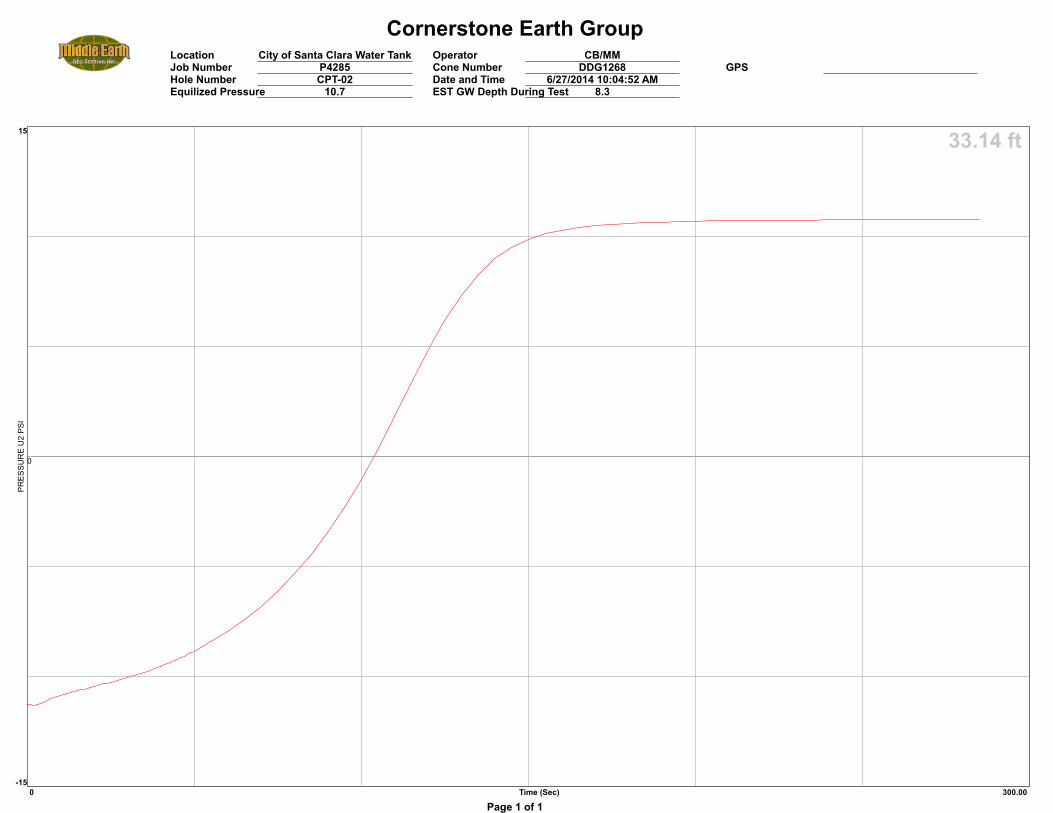
Cornerstone Earth GroupLocation City of Santa Clara Water Tank Operator CB/MMJob Number P4285 Cone Number DDG1268 GPSHole Number CPT-02 Date and Time 6/27/2014 10:04:52 AMEquilized Pressure 10.7 EST GW Depth During Test 8.3
33.14 ft
0
0 Time (Sec) 300.00
15
-15
PRES
SUR
E U
2 PS
I
Page 1 of 1
CITY OF SANTA CLARA CORP YARD WATER TANK 138-6-1
Page B-1
APPENDIX B: LABORATORY TEST PROGRAM The laboratory testing program was performed to evaluate the physical and mechanical properties of the soils retrieved from the site to aid in verifying soil classification. Moisture Content: The natural water content was determined (ASTM D2216) on 18 samples of the materials recovered from the borings. These water contents are recorded on the boring logs at the appropriate sample depths. Dry Densities: In place dry density determinations (ASTM D2937) were performed on 14 samples to measure the unit weight of the subsurface soils. Results of these tests are shown on the boring logs at the appropriate sample depths. Washed Sieve Analyses: The percent soil fraction passing the No. 200 sieve (ASTM D1140) was determined on (3) three samples of the subsurface soils to aid in the classification of these soils. Results of these tests are shown on the boring logs at the appropriate sample depths. Plasticity Index: One Plasticity Index determination (ASTM D4318) was performed on a sample of the subsurface soil to measure the range of water contents over which this material exhibits plasticity. The Plasticity Index was used to classify the soil in accordance with the Unified Soil Classification System and to evaluate the soil expansion potential. Results of this test are shown on the boring log at the appropriate sample depth. Consolidation: One consolidation test (ASTM D2435) was performed on a relatively undisturbed sample of the subsurface clayey soils to assist in evaluating the compressibility property of this soil. Results of the consolidation test are presented graphically in this appendix. Corrosivity Tests: One soluble sulfate determination (ASTM D4327), saturated resistivity (ASTM G57), chloride (ASTM D4327) and pH (ASTM G51) was performed on a sample of the subsurface soil to measure the corrosivity potential of the soil. Results of this test are attached is this appendix.
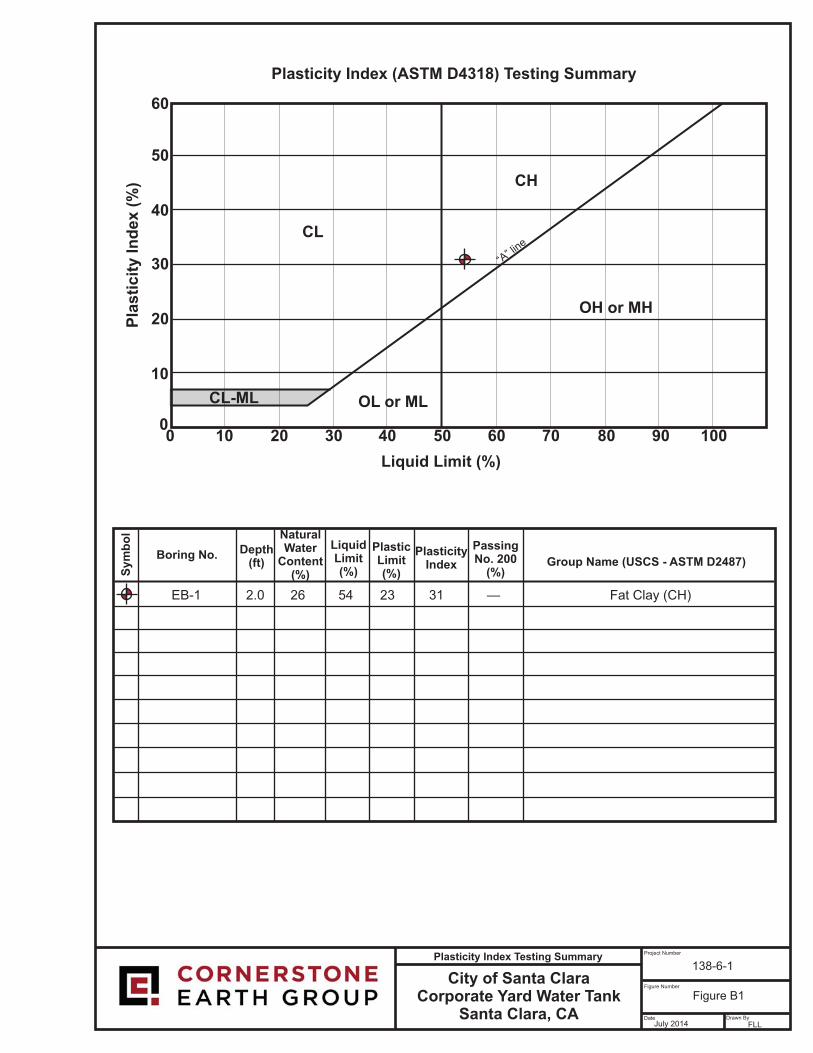
City of Santa ClaraCorporate Yard Water Tank
Santa Clara, CA
Project Number
Figure Number
Date Drawn By
138-6-1
Figure B1
July 2014 FLL
Plasticity Index Testing Summary
60
0
10
20
30
40
50
0 100908070605040302010
CL-ML OL or ML
OH or MH
CH
CL
Pla
sti
cit
y In
dex (
%)
Liquid Limit (%)
Group Name (USCS - ASTM D2487)Boring No.
Sym
bo
l
Depth(ft)
NaturalWater
Content(%)
LiquidLimit(%)
PlasticLimit(%)
PlasticityIndex
PassingNo. 200
(%)
“A” lin
e
Plasticity Index (ASTM D4318) Testing Summary
Fat Clay (CH)31EB-1 54 23262.0 —
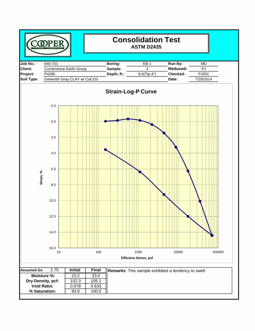
Job No.: Boring: Run By: MDClient: Sample: Reduced: PJProject: Depth, ft.: Checked: PJ/DCSoil Type: Date: 7/29/2014
EB-14
8.0(Tip-4")P4285Cornerstone Earth Group640-701
Greenish Gray CLAY w/ CaCO3
-2.0
0.0
2.0
4.0
6.0
%
Strain-Log-P Curve
Consolidation TestASTM D2435
Assumed Gs 2.75 Initial Final23.2 23.0102.3 105.10.678 0.63393.9 100.0% Saturation:
Dry Density, pcf: Moisture %:
Void Ratio:
8.0
10.0
12.0
14.0
16.010 100 1000 10000 100000
Stra
in,
Effective Stress, psf
Remarks: This sample exhibited a tendency to swell.
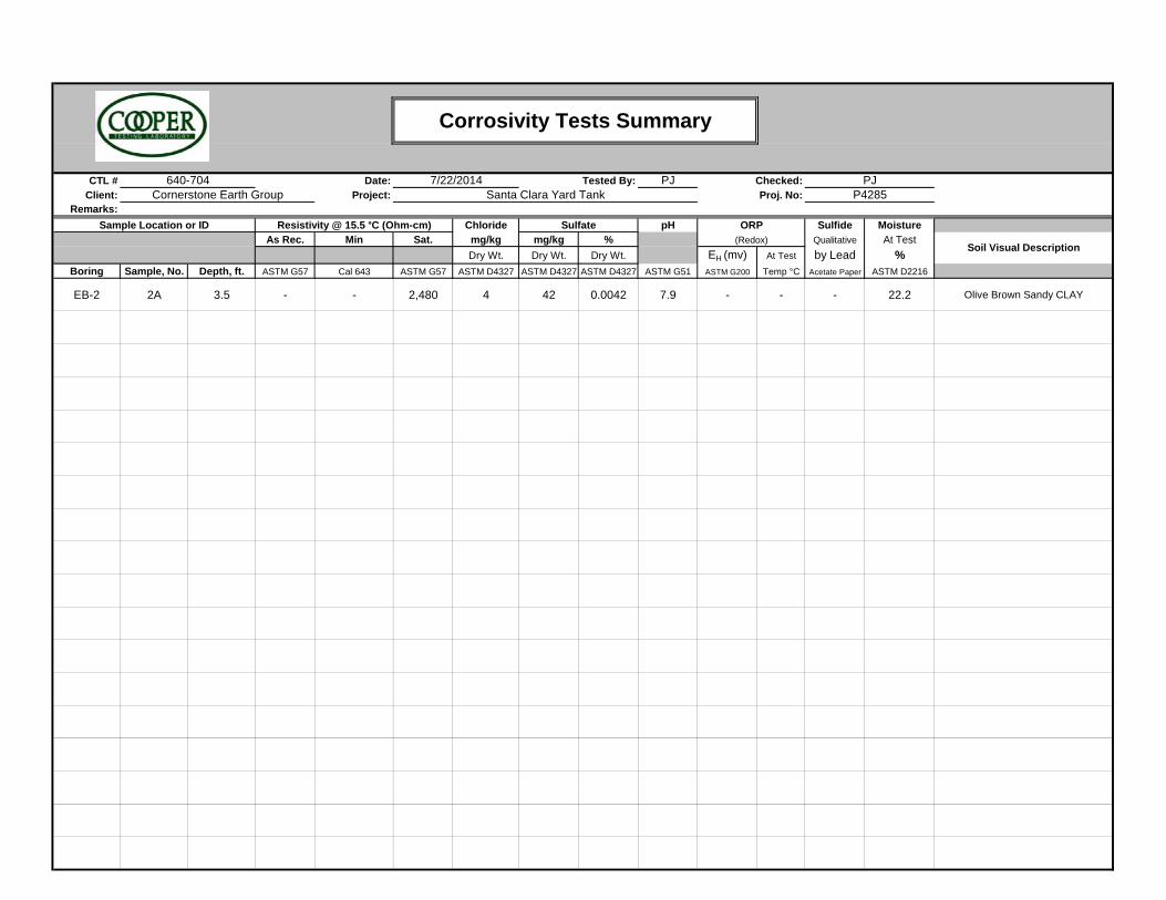
CTL # Date: PJClient: Project:
Remarks:Chloride pH Sulfide Moisture
As Rec. Min Sat. mg/kg mg/kg % Qualitative At Test
Dry Wt. Dry Wt. Dry Wt. EH (mv) At Test by Lead %Boring Sample, No. Depth, ft. ASTM G57 Cal 643 ASTM G57 ASTM D4327 ASTM D4327 ASTM D4327 ASTM G51 ASTM G200 Temp °C Acetate Paper ASTM D2216
EB-2 2A 3.5 - - 2,480 4 42 0.0042 7.9 - - - 22.2 Olive Brown Sandy CLAY
Corrosivity Tests Summary
(Redox)
PJP4285
Resistivity @ 15.5 °C (Ohm-cm)
Proj. No:Checked:7/22/2014
Cornerstone Earth Group
Soil Visual Description
640-704Santa Clara Yard Tank
Sample Location or ID Sulfate ORP
Tested By:
CITY OF SANTA CLARA CORP YARD WATER TANK 138-6-1
Page C-1
APPENDIX C: LIQUEFACTION ANALYSES CALCULATIONS
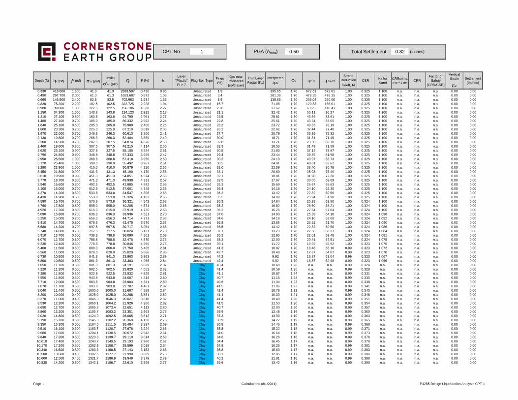
1 0.50 Total Settlement: 0.82 (Inches)
Depth (ft) qc (tsf) fs (tsf) σvc (psf)Insitu
σ'vc (psf)Q F (%) Ic
Layer "Plastic"PI > 7
Flag Soil TypeFines (%)
qcN near interfaces (soft layer)
Thin Layer Factor (KH)
Interpreted
qcNCN qc1N qc1N-CS
Stress Reduction
Coeff, rd
CSRKσ for Sand
CRRM=7.5,
σ'vc = 1 atmCRR
Factor of Safety
(CRR/CSR)
Vertical Strain
εv
Settlement (Inches)
0.330 418.600 1.800 41.3 41.3 2833.597 0.430 0.85 Unsaturated 1.9 395.65 1.70 672.61 672.61 1.00 0.325 1.100 n.a. n.a. n.a. 0.00 0.000.490 297.700 2.000 61.3 61.3 1653.687 0.672 1.08 Unsaturated 3.4 281.38 1.70 478.35 478.35 1.00 0.325 1.100 n.a. n.a. n.a. 0.00 0.000.660 146.900 2.400 82.5 82.5 702.983 1.634 1.56 Unsaturated 8.9 138.85 1.70 236.04 250.06 1.00 0.325 1.100 n.a. n.a. n.a. 0.00 0.000.820 75.200 2.200 102.5 102.5 322.725 2.928 1.94 Unsaturated 15.7 71.08 1.70 120.83 166.01 1.00 0.325 1.100 n.a. n.a. n.a. 0.00 0.000.980 39.800 1.800 122.5 122.5 156.106 4.530 2.27 Unsaturated 23.6 37.62 1.70 63.95 110.41 1.00 0.325 1.100 n.a. n.a. n.a. 0.00 0.001.150 34.300 1.000 143.8 143.8 124.123 2.922 2.18 Unsaturated 21.1 32.42 1.70 55.11 96.27 1.00 0.325 1.100 n.a. n.a. n.a. 0.00 0.001.310 27.100 0.800 163.8 163.8 91.799 2.961 2.27 Unsaturated 23.5 25.61 1.70 43.54 83.61 1.00 0.325 1.100 n.a. n.a. n.a. 0.00 0.001.480 27.100 0.700 185.0 185.0 86.332 2.592 2.24 Unsaturated 22.8 25.61 1.70 43.54 83.05 1.00 0.325 1.100 n.a. n.a. n.a. 0.00 0.001.640 25.100 0.600 205.0 205.0 75.909 2.400 2.26 Unsaturated 23.2 23.72 1.70 40.33 79.19 1.00 0.325 1.100 n.a. n.a. n.a. 0.00 0.001.800 23.300 0.700 225.0 225.0 67.210 3.019 2.36 Unsaturated 26.2 22.02 1.70 37.44 77.40 1.00 0.325 1.100 n.a. n.a. n.a. 0.00 0.001.970 22.000 0.700 246.3 246.3 60.613 3.200 2.41 Unsaturated 27.7 20.79 1.70 35.35 75.32 1.00 0.325 1.100 n.a. n.a. n.a. 0.00 0.002.130 19.800 0.700 266.3 266.3 52.404 3.559 2.49 Unsaturated 30.0 18.71 1.70 31.81 71.45 1.00 0.325 1.100 n.a. n.a. n.a. 0.00 0.002.300 14.500 0.700 287.5 287.5 54.874 4.876 2.58 Unsaturated 32.8 13.71 1.70 23.30 60.70 1.00 0.325 1.100 n.a. n.a. n.a. 0.00 0.002.460 19.600 0.800 307.5 307.5 48.215 4.114 2.56 Unsaturated 32.3 18.53 1.70 31.49 71.59 1.00 0.325 1.100 n.a. n.a. n.a. 0.00 0.002.620 23.100 0.900 327.5 327.5 55.105 3.924 2.51 Unsaturated 30.5 21.83 1.70 37.12 78.67 1.00 0.325 1.100 n.a. n.a. n.a. 0.00 0.002.790 24.800 0.900 348.8 348.8 57.333 3.655 2.47 Unsaturated 29.4 23.44 1.70 39.85 81.98 1.00 0.325 1.100 n.a. n.a. n.a. 0.00 0.002.950 25.500 1.000 368.8 368.8 57.318 3.950 2.50 Unsaturated 30.2 24.10 1.70 40.97 83.73 1.00 0.325 1.100 n.a. n.a. n.a. 0.00 0.003.120 25.400 1.000 390.0 390.0 55.492 3.967 2.51 Unsaturated 30.5 24.01 1.70 40.81 83.62 1.00 0.325 1.100 n.a. n.a. n.a. 0.00 0.003.280 23.900 1.000 410.0 410.0 50.879 4.220 2.55 Unsaturated 32.0 22.59 1.70 38.40 80.78 1.00 0.325 1.100 n.a. n.a. n.a. 0.00 0.003.450 21.800 0.900 431.3 431.3 45.190 4.170 2.58 Unsaturated 33.1 20.60 1.70 35.03 76.49 1.00 0.325 1.100 n.a. n.a. n.a. 0.00 0.003.610 19.900 0.900 451.3 451.3 54.851 4.574 2.56 Unsaturated 32.1 18.81 1.70 31.98 72.20 1.00 0.325 1.100 n.a. n.a. n.a. 0.00 0.003.770 18.700 0.800 471.3 471.3 49.938 4.333 2.57 Unsaturated 32.5 17.67 1.70 30.05 69.69 1.00 0.325 1.100 n.a. n.a. n.a. 0.00 0.003.940 16.600 0.800 492.5 492.5 42.885 4.892 2.65 Unsaturated 35.3 15.69 1.70 26.67 65.63 1.00 0.325 1.100 n.a. n.a. n.a. 0.00 0.004.100 15.000 0.700 512.5 512.5 37.601 4.748 2.68 Unsaturated 36.4 14.18 1.70 24.10 62.30 1.00 0.325 1.100 n.a. n.a. n.a. 0.00 0.004.270 14.200 0.600 533.8 533.8 34.537 4.306 2.68 Unsaturated 36.2 13.42 1.70 22.82 60.56 1.00 0.325 1.100 n.a. n.a. n.a. 0.00 0.004.430 14.900 0.600 553.8 553.8 35.326 4.103 2.66 Unsaturated 35.5 14.08 1.70 23.94 61.98 1.00 0.325 1.100 n.a. n.a. n.a. 0.00 0.004.590 15.700 0.700 573.8 573.8 36.321 4.542 2.68 Unsaturated 36.3 14.84 1.70 25.23 63.80 1.00 0.324 1.100 n.a. n.a. n.a. 0.00 0.004.760 17.800 0.800 595.0 595.0 40.208 4.571 2.65 Unsaturated 35.2 16.82 1.70 28.60 68.21 1.00 0.324 1.100 n.a. n.a. n.a. 0.00 0.004.920 17.200 0.800 615.0 615.0 37.919 4.736 2.68 Unsaturated 36.2 16.26 1.70 27.64 67.04 1.00 0.324 1.100 n.a. n.a. n.a. 0.00 0.005.090 15.800 0.700 636.3 636.3 33.936 4.521 2.70 Unsaturated 37.0 14.93 1.70 25.39 64.10 1.00 0.324 1.096 n.a. n.a. n.a. 0.00 0.005.250 15.000 0.700 656.3 656.3 44.714 4.771 2.63 Unsaturated 34.6 14.18 1.70 24.10 62.08 1.00 0.324 1.092 n.a. n.a. n.a. 0.00 0.005 410 14 700 0 800 676 3 676 3 42 475 5 570 2 69 Unsaturated 36 8 13 89 1 70 23 62 61 70 1 00 0 324 1 090 n a n a n a 0 00 0 00
CPT No. PGA (Amax)
5.410 14.700 0.800 676.3 676.3 42.475 5.570 2.69 Unsaturated 36.8 13.89 1.70 23.62 61.70 1.00 0.324 1.090 n.a. n.a. n.a. 0.00 0.005.580 14.200 0.700 697.5 697.5 39.717 5.054 2.68 Unsaturated 36.5 13.42 1.70 22.82 60.58 1.00 0.324 1.086 n.a. n.a. n.a. 0.00 0.005.740 14.000 0.700 717.5 717.5 38.024 5.131 2.70 Unsaturated 37.1 13.23 1.70 22.50 60.21 1.00 0.324 1.084 n.a. n.a. n.a. 0.00 0.005.910 13.700 0.600 738.8 738.8 36.090 4.501 2.68 Unsaturated 36.2 12.95 1.70 22.01 59.48 1.00 0.324 1.081 n.a. n.a. n.a. 0.00 0.006.070 12.700 0.600 758.8 758.8 32.476 4.870 2.73 Unsaturated 38.3 12.00 1.70 20.41 57.51 1.00 0.324 1.078 n.a. n.a. n.a. 0.00 0.006.230 12.400 0.600 778.8 778.8 30.846 4.996 2.76 Unsaturated 39.1 11.72 1.70 19.92 56.92 1.00 0.323 1.075 n.a. n.a. n.a. 0.00 0.006.400 11.500 0.600 800.0 800.0 27.750 5.405 2.81 Unsaturated 41.3 10.87 1.70 18.48 55.10 0.99 0.323 1.072 n.a. n.a. n.a. 0.00 0.006.560 11.000 0.600 820.0 820.0 25.829 5.666 2.85 Unsaturated 42.7 10.40 1.70 17.67 54.07 0.99 0.323 1.070 n.a. n.a. n.a. 0.00 0.006.730 10.500 0.600 841.3 841.3 23.963 5.953 2.89 Unsaturated 44.2 9.92 1.70 16.87 53.04 0.99 0.323 1.067 n.a. n.a. n.a. 0.00 0.006.890 10.500 0.500 861.3 861.3 23.383 4.966 2.84 Unsaturated 42.4 9.92 1.70 16.87 52.98 0.99 0.323 1.066 n.a. n.a. n.a. 0.00 0.007.050 11.100 0.600 881.3 881.3 24.191 5.629 2.87 Clay 43.4 10.49 1.26 n.a. n.a. 0.99 0.324 n.a. n.a. n.a. n.a. 0.00 0.007.220 11.200 0.500 902.5 902.5 23.820 4.652 2.82 Clay 41.4 10.59 1.25 n.a. n.a. 0.99 0.328 n.a. n.a. n.a. n.a. 0.00 0.007.380 11.500 0.500 922.5 922.5 23.932 4.529 2.81 Clay 41.1 10.87 1.24 n.a. n.a. 0.99 0.331 n.a. n.a. n.a. n.a. 0.00 0.007.550 11.800 0.500 943.8 943.8 24.007 4.414 2.80 Clay 40.7 11.15 1.24 n.a. n.a. 0.99 0.335 n.a. n.a. n.a. n.a. 0.00 0.007.710 12.000 0.500 963.8 963.8 23.903 4.341 2.80 Clay 40.6 11.34 1.23 n.a. n.a. 0.99 0.338 n.a. n.a. n.a. n.a. 0.00 0.007.870 11.700 0.500 983.8 983.8 22.787 4.461 2.82 Clay 41.5 11.06 1.22 n.a. n.a. 0.99 0.341 n.a. n.a. n.a. n.a. 0.00 0.008.040 11.400 0.500 1005.0 1005.0 21.687 4.588 2.84 Clay 42.4 10.78 1.22 n.a. n.a. 0.99 0.345 n.a. n.a. n.a. n.a. 0.00 0.008.200 10.900 0.400 1025.0 1025.0 20.268 3.851 2.82 Clay 41.4 10.30 1.21 n.a. n.a. 0.99 0.348 n.a. n.a. n.a. n.a. 0.00 0.008.370 11.000 0.400 1046.3 1046.3 20.027 3.818 2.82 Clay 41.4 10.40 1.20 n.a. n.a. 0.99 0.351 n.a. n.a. n.a. n.a. 0.00 0.008.530 12.200 0.500 1066.1 1064.2 21.926 4.286 2.82 Clay 41.5 11.53 1.20 n.a. n.a. 0.99 0.354 n.a. n.a. n.a. n.a. 0.00 0.008.690 12.700 0.500 1085.3 1073.4 22.651 4.113 2.80 Clay 40.7 12.00 1.20 n.a. n.a. 0.99 0.357 n.a. n.a. n.a. n.a. 0.00 0.008.860 13.200 0.500 1105.7 1083.2 23.351 3.953 2.78 Clay 39.9 12.48 1.19 n.a. n.a. 0.99 0.360 n.a. n.a. n.a. n.a. 0.00 0.009.020 14.800 0.500 1124.9 1092.5 26.065 3.512 2.71 Clay 37.3 13.99 1.19 n.a. n.a. 0.99 0.363 n.a. n.a. n.a. n.a. 0.00 0.009.190 15.100 0.600 1145.3 1102.2 26.360 4.130 2.75 Clay 38.9 14.27 1.19 n.a. n.a. 0.99 0.365 n.a. n.a. n.a. n.a. 0.00 0.009.350 15.300 0.500 1164.5 1111.5 26.484 3.397 2.69 Clay 36.8 14.46 1.19 n.a. n.a. 0.99 0.368 n.a. n.a. n.a. n.a. 0.00 0.009.510 16.100 0.500 1183.7 1120.7 27.676 3.224 2.66 Clay 35.8 15.22 1.18 n.a. n.a. 0.99 0.371 n.a. n.a. n.a. n.a. 0.00 0.009.680 17.600 0.500 1204.1 1130.5 30.072 2.942 2.61 Clay 34.0 16.64 1.18 n.a. n.a. 0.99 0.373 n.a. n.a. n.a. n.a. 0.00 0.009.840 17.200 0.500 1223.3 1139.7 29.110 3.014 2.63 Clay 34.6 16.26 1.18 n.a. n.a. 0.99 0.376 n.a. n.a. n.a. n.a. 0.00 0.00
10.010 17.400 0.500 1243.7 1149.5 29.193 2.980 2.62 Clay 34.4 16.45 1.17 n.a. n.a. 0.99 0.378 n.a. n.a. n.a. n.a. 0.00 0.0010.170 17.200 0.500 1262.9 1158.7 28.599 3.018 2.64 Clay 34.8 16.26 1.17 n.a. n.a. 0.99 0.381 n.a. n.a. n.a. n.a. 0.00 0.0010.340 16.500 0.500 1283.3 1168.5 27.143 3.153 2.66 Clay 35.8 15.60 1.17 n.a. n.a. 0.99 0.383 n.a. n.a. n.a. n.a. 0.00 0.0010.500 13.600 0.400 1302.5 1177.7 21.990 3.089 2.73 Clay 38.1 12.85 1.17 n.a. n.a. 0.99 0.386 n.a. n.a. n.a. n.a. 0.00 0.0010.660 12.500 0.400 1321.7 1186.9 19.949 3.379 2.79 Clay 40.2 11.81 1.16 n.a. n.a. 0.99 0.388 n.a. n.a. n.a. n.a. 0.00 0.0010.830 14.200 0.500 1342.1 1196.7 22.610 3.696 2.77 Clay 39.6 13.42 1.16 n.a. n.a. 0.99 0.390 n.a. n.a. n.a. n.a. 0.00 0.00
Page 1 Calculations (8/1/2014) P4285 Design Liquefaction Analysis CPT-1
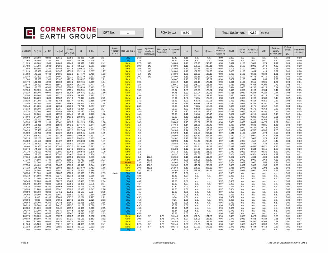
1 0.50 Total Settlement: 0.82 (Inches)
Depth (ft) qc (tsf) fs (tsf) σvc (psf)Insitu
σ'vc (psf)Q F (%) Ic
Layer "Plastic"PI > 7
Flag Soil TypeFines (%)
qcN near interfaces (soft layer)
Thin Layer Factor (KH)
Interpreted
qcNCN qc1N qc1N-CS
Stress Reduction
Coeff, rd
CSRKσ for Sand
CRRM=7.5,
σ'vc = 1 atmCRR
Factor of Safety
(CRR/CSR)
Vertical Strain
εv
Settlement (Inches)
CPT No. PGA (Amax)
10.990 20.600 0.800 1361.3 1205.9 33.036 4.016 2.67 Clay 36.0 19.47 1.16 n.a. n.a. 0.99 0.392 n.a. n.a. n.a. n.a. 0.00 0.0011.160 26.700 1.100 1381.7 1215.7 42.788 4.229 2.61 Clay 33.8 25.24 1.16 n.a. n.a. 0.99 0.395 n.a. n.a. n.a. n.a. 0.00 0.0011.320 48.900 1.500 1400.9 1224.9 59.877 3.112 2.41 Sand 27.5 143 143.00 1.16 165.75 248.40 0.98 0.397 1.100 2.000 1.979 4.99 0.00 0.0011.480 77.200 1.500 1420.1 1234.1 94.666 1.961 2.13 Sand 19.9 143 143.00 1.16 166.59 237.11 0.98 0.399 1.100 2.000 1.979 4.96 0.00 0.0011.650 90.700 1.100 1440.5 1243.9 110.922 1.222 1.93 Sand 15.6 143 143.00 1.17 167.78 222.43 0.98 0.401 1.100 2.000 1.979 4.93 0.00 0.0011.810 108.300 0.900 1459.7 1253.2 132.118 0.837 1.77 Sand 12.3 143 143.00 1.18 169.38 204.78 0.98 0.403 1.100 1.434 1.419 3.52 0.00 0.0011.980 143.600 0.700 1480.1 1262.9 174.779 0.490 1.53 Sand 8.4 143 143.00 1.20 171.93 180.12 0.98 0.405 1.100 0.538 0.532 1.31 0.00 0.0012.140 150.200 1.200 1499.3 1272.2 182.179 0.803 1.65 Sand 10.3 143 143.00 1.19 170.16 190.94 0.98 0.407 1.100 0.778 0.770 1.89 0.00 0.0012.300 152.000 1.500 1518.5 1281.4 183.697 0.992 1.71 Sand 11.3 143.67 1.18 169.71 198.09 0.98 0.409 1.100 1.044 1.033 2.53 0.00 0.0012.470 141.900 1.000 1538.9 1291.2 170.766 0.709 1.64 Sand 10.1 134.12 1.19 160.18 178.41 0.98 0.411 1.100 0.511 0.505 1.23 0.00 0.0112.630 127.500 0.600 1558.1 1300.4 152.786 0.473 1.57 Sand 9.0 120.51 1.21 145.92 156.36 0.98 0.413 1.082 0.304 0.296 0.72 0.02 0.0312.800 108.700 0.500 1578.5 1310.2 129.620 0.463 1.62 Sand 9.8 102.74 1.22 125.68 139.88 0.98 0.414 1.070 0.232 0.223 0.54 0.02 0.0412.960 93.500 0.400 1597.7 1319.4 110.961 0.431 1.66 Sand 10.5 88.37 1.23 109.08 125.84 0.98 0.416 1.062 0.193 0.184 0.44 0.03 0.0513.120 89.700 0.900 1616.9 1328.6 106.031 1.012 1.89 Sand 14.7 84.78 1.22 103.04 140.61 0.98 0.418 1.069 0.234 0.225 0.54 0.02 0.0513.290 80.500 1.500 1637.3 1338.4 94.697 1.882 2.11 Sand 19.6 76.09 1.21 92.14 141.31 0.98 0.420 1.068 0.237 0.228 0.54 0.02 0.0413.450 66.700 1.800 1656.5 1347.6 78.017 2.733 2.29 Sand 24.1 63.04 1.22 76.95 127.92 0.98 0.421 1.060 0.198 0.188 0.45 0.02 0.0513.620 54.200 1.700 1676.9 1357.4 62.972 3.186 2.40 Sand 27.3 51.23 1.23 63.18 112.08 0.98 0.423 1.052 0.164 0.155 0.37 0.03 0.0513.780 56.000 1.500 1696.1 1366.6 64.865 2.720 2.34 Sand 25.6 52.93 1.23 65.00 113.43 0.98 0.425 1.052 0.166 0.157 0.37 0.03 0.0513.940 61.200 1.000 1715.3 1375.8 70.731 1.657 2.17 Sand 20.9 57.84 1.22 70.65 116.02 0.98 0.426 1.052 0.171 0.162 0.38 0.03 0.0614.110 59.800 1.200 1735.7 1385.6 68.834 2.036 2.24 Sand 22.7 56.52 1.22 68.82 115.87 0.98 0.428 1.051 0.171 0.162 0.38 0.03 0.0514.270 75.000 1.000 1754.9 1394.9 86.290 1.349 2.04 Sand 18.0 70.89 1.20 85.15 128.90 0.98 0.429 1.056 0.200 0.190 0.44 0.02 0.0514.440 82.900 1.000 1775.3 1404.6 95.141 1.219 1.98 Sand 16.6 78.36 1.19 93.38 135.45 0.98 0.431 1.058 0.218 0.208 0.48 0.02 0.0414.600 94.300 0.800 1794.5 1413.9 108.001 0.857 1.84 Sand 13.7 89.13 1.19 105.65 139.15 0.98 0.432 1.059 0.230 0.219 0.51 0.02 0.0414.760 106.000 1.000 1813.7 1423.1 121.125 0.952 1.83 Sand 13.5 100.19 1.17 117.41 152.10 0.98 0.434 1.065 0.281 0.269 0.62 0.02 0.0414.930 141.200 1.100 1834.1 1432.9 161.129 0.784 1.68 Sand 10.9 133.46 1.15 153.67 176.87 0.98 0.435 1.080 0.489 0.475 1.09 0.01 0.0115.090 156.200 1.000 1853.3 1442.1 177.776 0.644 1.60 Sand 9.4 147.64 1.14 168.99 183.40 0.98 0.437 1.084 0.596 0.581 1.33 0.00 0.0015.260 164.500 1.100 1873.7 1451.9 186.635 0.673 1.59 Sand 9.4 155.48 1.14 176.82 191.25 0.98 0.438 1.090 0.787 0.772 1.76 0.00 0.0015.420 170.400 0.900 1892.9 1461.1 192.745 0.531 1.52 Sand 8.3 161.06 1.14 182.84 190.38 0.97 0.439 1.087 0.762 0.745 1.70 0.00 0.0015.580 186.200 1.000 1912.1 1470.3 210.045 0.540 1.49 Sand 7.9 175.99 1.13 198.03 204.12 0.97 0.441 1.100 1.387 1.373 3.12 0.00 0.0015.750 213.800 1.100 1932.5 1480.1 240.529 0.517 1.43 Sand 7.1 202.08 1.11 224.51 227.64 0.97 0.442 1.100 2.000 1.979 4.48 0.00 0.0015.910 202.100 1.000 1951.7 1489.3 226.591 0.497 1.44 Sand 7.3 191.02 1.11 212.87 216.32 0.97 0.443 1.100 2.000 1.979 4.46 0.00 0.0016 080 193 600 0 800 1972 1 1499 1 216 293 0 415 1 41 Sand 6 9 182 99 1 12 204 40 206 43 0 97 0 445 1 098 1 562 1 542 3 47 0 00 0 0016.080 193.600 0.800 1972.1 1499.1 216.293 0.415 1.41 Sand 6.9 182.99 1.12 204.40 206.43 0.97 0.445 1.098 1.562 1.542 3.47 0.00 0.0016.240 193.400 0.700 1991.3 1508.3 215.397 0.364 1.38 Sand 6.5 182.80 1.12 203.91 205.06 0.97 0.446 1.094 1.454 1.432 3.21 0.00 0.0016.400 181.900 0.700 2010.5 1517.5 201.896 0.387 1.42 Sand 6.9 171.93 1.12 192.31 194.48 0.97 0.447 1.082 0.895 0.871 1.95 0.00 0.0016.570 174.600 0.400 2030.9 1527.3 193.115 0.230 1.32 Sand 5.8 165.03 1.12 184.96 185.24 0.97 0.448 1.073 0.634 0.611 1.36 0.00 0.0016.730 171.100 0.300 2050.1 1536.5 188.642 0.176 1.28 Sand 5.3 161.72 1.12 181.19 181.29 0.97 0.449 1.069 0.557 0.536 1.19 0.01 0.0116.900 172.000 0.400 2070.5 1546.3 189.028 0.234 1.33 Sand 5.9 162.57 1.12 181.67 182.05 0.97 0.451 1.068 0.571 0.548 1.22 0.00 0.0117.060 139.100 0.800 2089.7 1555.6 152.189 0.579 1.62 Sand 9.8 162.6 162.60 1.11 180.11 197.86 0.97 0.452 1.079 1.034 1.003 2.22 0.00 0.0017.230 74.500 1.700 2110.1 1565.3 80.710 2.315 2.23 Sand 22.4 162.6 162.60 1.08 176.06 255.10 0.97 0.453 1.090 2.000 1.962 4.33 0.00 0.0017.390 32.000 1.100 2129.3 1574.6 35.960 3.556 2.61 Mixed 33.8 162.6 162.60 1.08 175.79 265.61 0.97 0.454 1.089 2.000 1.958 4.31 0.00 0.0017.550 46.400 0.700 2148.5 1583.8 49.519 1.544 2.27 Sand 23.5 162.6 162.60 1.08 175.52 256.31 0.97 0.455 1.087 2.000 1.955 4.30 0.00 0.0017.720 104.900 0.500 2168.9 1593.6 113.070 0.482 1.68 Sand 10.8 162.6 162.60 1.10 178.30 203.32 0.97 0.456 1.077 1.333 1.292 2.83 0.00 0.0017.880 74.300 1.000 2188.1 1602.8 79.502 1.366 2.07 Sand 18.7 162.6 162.60 1.08 175.48 244.71 0.97 0.457 1.083 2.000 1.949 4.26 0.00 0.0018.050 31.800 1.000 2208.5 1612.6 35.090 3.258 2.59 plastic Clay 33.2 30.06 1.07 n.a. n.a. 0.97 0.458 n.a. n.a. n.a. n.a. 0.00 0.0018.210 14.600 0.500 2227.7 1621.8 16.631 3.708 2.87 Clay 43.6 13.80 1.07 n.a. n.a. 0.97 0.459 n.a. n.a. n.a. n.a. 0.00 0.0018.370 12.900 0.400 2246.9 1631.0 14.441 3.397 2.90 Clay 44.6 12.19 1.07 n.a. n.a. 0.97 0.460 n.a. n.a. n.a. n.a. 0.00 0.0018.540 12.200 0.400 2267.3 1640.8 13.489 3.615 2.94 Clay 46.2 11.53 1.07 n.a. n.a. 0.97 0.461 n.a. n.a. n.a. n.a. 0.00 0.0018.700 10.900 0.300 2286.5 1650.0 11.826 3.075 2.94 Clay 46.4 10.30 1.07 n.a. n.a. 0.97 0.462 n.a. n.a. n.a. n.a. 0.00 0.0018.870 10.900 0.300 2306.9 1659.8 11.744 3.078 2.95 Clay 46.5 10.30 1.07 n.a. n.a. 0.97 0.463 n.a. n.a. n.a. n.a. 0.00 0.0019.030 11.700 0.300 2326.1 1669.0 12.626 2.847 2.90 Clay 44.6 11.06 1.06 n.a. n.a. 0.97 0.464 n.a. n.a. n.a. n.a. 0.00 0.0019.190 10.900 0.300 2345.3 1678.2 11.592 3.084 2.95 Clay 46.7 10.30 1.06 n.a. n.a. 0.97 0.465 n.a. n.a. n.a. n.a. 0.00 0.0019.360 10.300 0.200 2365.7 1688.0 10.802 2.194 2.89 Clay 44.4 9.74 1.06 n.a. n.a. 0.96 0.466 n.a. n.a. n.a. n.a. 0.00 0.0019.520 9.900 0.200 2384.9 1697.3 10.261 2.297 2.92 Clay 45.5 9.36 1.06 n.a. n.a. 0.96 0.467 n.a. n.a. n.a. n.a. 0.00 0.0019.690 9.800 0.200 2405.3 1707.0 10.073 2.326 2.93 Clay 45.9 9.26 1.06 n.a. n.a. 0.96 0.468 n.a. n.a. n.a. n.a. 0.00 0.0019.850 10.700 0.200 2424.5 1716.3 11.056 2.108 2.88 Clay 43.6 10.11 1.06 n.a. n.a. 0.96 0.469 n.a. n.a. n.a. n.a. 0.00 0.0020.010 10.800 0.200 2443.7 1725.5 11.102 2.088 2.87 Clay 43.5 10.21 1.06 n.a. n.a. 0.96 0.469 n.a. n.a. n.a. n.a. 0.00 0.0020.180 11.200 0.300 2464.1 1735.3 11.489 3.010 2.95 Clay 46.6 10.59 1.05 n.a. n.a. 0.96 0.470 n.a. n.a. n.a. n.a. 0.00 0.0020.340 12.000 0.400 2483.3 1744.5 12.334 3.718 2.98 Clay 47.8 11.34 1.05 n.a. n.a. 0.96 0.471 n.a. n.a. n.a. n.a. 0.00 0.0020.510 14.100 0.500 2503.7 1754.3 14.648 3.892 2.93 Clay 45.8 13.33 1.05 n.a. n.a. 0.96 0.472 n.a. n.a. n.a. n.a. 0.00 0.0020.670 33.200 0.400 2522.9 1763.5 33.067 1.252 2.35 Sand 25.9 57 1.78 101.46 1.07 108.54 171.20 0.96 0.473 1.035 0.420 0.391 0.83 0.01 0.0220.830 60.500 0.700 2542.1 1772.7 61.163 1.182 2.12 Sand 19.8 1.78 101.79 1.07 108.91 163.19 0.96 0.473 1.032 0.348 0.323 0.68 0.02 0.0321.000 51.800 0.900 2562.5 1782.5 52.025 1.782 2.29 Sand 24.1 57 1.78 101.46 1.07 108.17 168.92 0.96 0.474 1.033 0.397 0.369 0.78 0.01 0.0221.160 45.100 1.000 2581.7 1791.7 44.999 2.283 2.41 Sand 27.5 57 1.78 101.46 1.06 107.89 171.54 0.96 0.475 1.032 0.423 0.393 0.83 0.01 0.0221.330 36.600 1.000 2602.1 1801.5 36.159 2.833 2.54 Sand 31.6 57 1.78 101.46 1.06 107.63 173.36 0.96 0.476 1.032 0.444 0.412 0.87 0.01 0.0221.490 20.100 0.500 2621.3 1810.7 20.753 2.661 2.71 Clay 37.4 19.00 1.04 n.a. n.a. 0.96 0.476 n.a. n.a. n.a. n.a. 0.00 0.00
Page 2 Calculations (8/1/2014) P4285 Design Liquefaction Analysis CPT-1
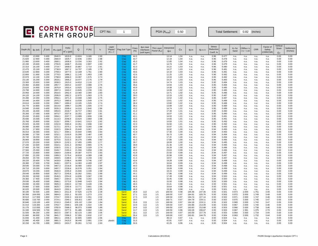
1 0.50 Total Settlement: 0.82 (Inches)
Depth (ft) qc (tsf) fs (tsf) σvc (psf)Insitu
σ'vc (psf)Q F (%) Ic
Layer "Plastic"PI > 7
Flag Soil TypeFines (%)
qcN near interfaces (soft layer)
Thin Layer Factor (KH)
Interpreted
qcNCN qc1N qc1N-CS
Stress Reduction
Coeff, rd
CSRKσ for Sand
CRRM=7.5,
σ'vc = 1 atmCRR
Factor of Safety
(CRR/CSR)
Vertical Strain
εv
Settlement (Inches)
CPT No. PGA (Amax)
21.650 13.900 0.400 2640.5 1819.9 13.824 3.180 2.90 Clay 44.5 13.14 1.04 n.a. n.a. 0.96 0.477 n.a. n.a. n.a. n.a. 0.00 0.0021.820 12.900 0.300 2660.9 1829.7 12.646 2.593 2.88 Clay 43.7 12.19 1.04 n.a. n.a. 0.96 0.478 n.a. n.a. n.a. n.a. 0.00 0.0021.980 13.600 0.400 2680.1 1838.9 13.334 3.263 2.92 Clay 45.3 12.85 1.04 n.a. n.a. 0.96 0.479 n.a. n.a. n.a. n.a. 0.00 0.0022.150 15.600 0.400 2700.5 1848.7 15.416 2.807 2.83 Clay 41.7 14.74 1.04 n.a. n.a. 0.96 0.479 n.a. n.a. n.a. n.a. 0.00 0.0022.310 16.100 0.400 2719.7 1858.0 15.867 2.714 2.81 Clay 41.0 15.22 1.03 n.a. n.a. 0.96 0.480 n.a. n.a. n.a. n.a. 0.00 0.0022.470 15.100 0.300 2738.9 1867.2 14.707 2.185 2.78 Clay 40.0 14.27 1.03 n.a. n.a. 0.96 0.481 n.a. n.a. n.a. n.a. 0.00 0.0022.640 12.800 0.200 2759.3 1877.0 12.169 1.751 2.80 Clay 40.6 12.10 1.03 n.a. n.a. 0.96 0.481 n.a. n.a. n.a. n.a. 0.00 0.0022.800 11.900 0.200 2778.5 1886.2 11.145 1.903 2.85 Clay 42.6 11.25 1.03 n.a. n.a. 0.96 0.482 n.a. n.a. n.a. n.a. 0.00 0.0022.970 14.100 0.200 2798.9 1896.0 13.397 1.575 2.74 Clay 38.4 13.33 1.03 n.a. n.a. 0.95 0.482 n.a. n.a. n.a. n.a. 0.00 0.0023.130 15.200 0.300 2818.1 1905.2 14.477 2.175 2.79 Clay 40.2 14.37 1.03 n.a. n.a. 0.95 0.483 n.a. n.a. n.a. n.a. 0.00 0.0023.300 15.600 0.300 2838.5 1915.0 14.810 2.116 2.77 Clay 39.6 14.74 1.03 n.a. n.a. 0.95 0.484 n.a. n.a. n.a. n.a. 0.00 0.0023.460 15.800 0.300 2857.7 1924.2 14.937 2.088 2.76 Clay 39.4 14.93 1.03 n.a. n.a. 0.95 0.484 n.a. n.a. n.a. n.a. 0.00 0.0023.620 14.900 0.300 2876.9 1933.4 13.925 2.229 2.81 Clay 40.9 14.08 1.02 n.a. n.a. 0.95 0.485 n.a. n.a. n.a. n.a. 0.00 0.0023.790 14.900 0.300 2897.3 1943.2 13.845 2.230 2.81 Clay 41.0 14.08 1.02 n.a. n.a. 0.95 0.485 n.a. n.a. n.a. n.a. 0.00 0.0023.950 14.500 0.300 2916.5 1952.4 13.360 2.300 2.83 Clay 41.8 13.71 1.02 n.a. n.a. 0.95 0.486 n.a. n.a. n.a. n.a. 0.00 0.0024.120 14.100 0.200 2936.9 1962.2 12.875 1.583 2.75 Clay 39.0 13.33 1.02 n.a. n.a. 0.95 0.487 n.a. n.a. n.a. n.a. 0.00 0.0024.280 14.300 0.200 2956.1 1971.4 13.008 1.560 2.75 Clay 38.7 13.52 1.02 n.a. n.a. 0.95 0.487 n.a. n.a. n.a. n.a. 0.00 0.0024.440 14.400 0.200 2975.3 1980.6 13.039 1.549 2.74 Clay 38.7 13.61 1.02 n.a. n.a. 0.95 0.488 n.a. n.a. n.a. n.a. 0.00 0.0024.610 14.600 0.200 2995.7 1990.4 13.165 1.526 2.74 Clay 38.4 13.80 1.02 n.a. n.a. 0.95 0.488 n.a. n.a. n.a. n.a. 0.00 0.0024.770 14.800 0.200 3014.9 1999.7 13.295 1.505 2.73 Clay 38.2 13.99 1.02 n.a. n.a. 0.95 0.489 n.a. n.a. n.a. n.a. 0.00 0.0024.940 15.600 0.400 3035.3 2009.4 14.016 2.840 2.86 Clay 43.2 14.74 1.01 n.a. n.a. 0.95 0.489 n.a. n.a. n.a. n.a. 0.00 0.0025.100 18.400 0.500 3054.5 2018.7 16.717 2.963 2.81 Clay 41.2 17.39 1.01 n.a. n.a. 0.95 0.490 n.a. n.a. n.a. n.a. 0.00 0.0025.260 17.000 0.400 3073.7 2027.9 15.251 2.587 2.81 Clay 41.1 16.07 1.01 n.a. n.a. 0.95 0.490 n.a. n.a. n.a. n.a. 0.00 0.0025.430 15.800 0.400 3094.1 2037.7 13.989 2.806 2.86 Clay 43.1 14.93 1.01 n.a. n.a. 0.95 0.491 n.a. n.a. n.a. n.a. 0.00 0.0025.590 15.500 0.400 3113.3 2046.9 13.624 2.869 2.88 Clay 43.6 14.65 1.01 n.a. n.a. 0.95 0.491 n.a. n.a. n.a. n.a. 0.00 0.0025.760 15.800 0.500 3133.7 2056.7 13.841 3.513 2.92 Clay 45.5 14.93 1.01 n.a. n.a. 0.95 0.492 n.a. n.a. n.a. n.a. 0.00 0.0025.920 16.400 0.400 3152.9 2065.9 14.351 2.698 2.84 Clay 42.3 15.50 1.01 n.a. n.a. 0.95 0.492 n.a. n.a. n.a. n.a. 0.00 0.0026.080 16.900 0.500 3172.1 2075.1 14.760 3.265 2.88 Clay 43.9 15.97 1.01 n.a. n.a. 0.95 0.493 n.a. n.a. n.a. n.a. 0.00 0.0026.250 17.900 0.500 3192.5 2084.9 15.640 3.067 2.84 Clay 42.4 16.92 1.00 n.a. n.a. 0.94 0.493 n.a. n.a. n.a. n.a. 0.00 0.0026.410 18.300 0.500 3211.7 2094.1 15.944 2.995 2.83 Clay 41.9 17.30 1.00 n.a. n.a. 0.94 0.493 n.a. n.a. n.a. n.a. 0.00 0.0026.580 17.700 0.400 3232.1 2103.9 15.290 2.487 2.80 Clay 40.7 16.73 1.00 n.a. n.a. 0.94 0.494 n.a. n.a. n.a. n.a. 0.00 0.0026 740 18 200 0 400 3251 3 2113 1 15 687 2 413 2 78 Clay 40 1 17 20 1 00 n a n a 0 94 0 494 n a n a n a n a 0 00 0 0026.740 18.200 0.400 3251.3 2113.1 15.687 2.413 2.78 Clay 40.1 17.20 1.00 n.a. n.a. 0.94 0.494 n.a. n.a. n.a. n.a. 0.00 0.0026.900 18.900 0.500 3270.5 2122.3 16.270 2.896 2.82 Clay 41.3 17.86 1.00 n.a. n.a. 0.94 0.495 n.a. n.a. n.a. n.a. 0.00 0.0027.070 20.200 0.500 3290.9 2132.1 17.405 2.695 2.77 Clay 39.7 19.09 1.00 n.a. n.a. 0.94 0.495 n.a. n.a. n.a. n.a. 0.00 0.0027.230 22.600 0.600 3310.1 2141.3 19.562 2.865 2.75 Clay 38.8 21.36 1.00 n.a. n.a. 0.94 0.495 n.a. n.a. n.a. n.a. 0.00 0.0027.400 25.700 0.800 3330.5 2151.1 22.346 3.329 2.74 Clay 38.7 24.29 1.00 n.a. n.a. 0.94 0.496 n.a. n.a. n.a. n.a. 0.00 0.0027.560 25.000 0.900 3349.7 2160.4 21.594 3.858 2.80 Clay 40.6 23.63 0.99 n.a. n.a. 0.94 0.496 n.a. n.a. n.a. n.a. 0.00 0.0027.720 23.800 0.900 3368.9 2169.6 20.387 4.070 2.83 Clay 41.9 22.50 0.99 n.a. n.a. 0.94 0.497 n.a. n.a. n.a. n.a. 0.00 0.0027.890 22.200 0.900 3389.3 2179.4 18.818 4.389 2.88 Clay 43.8 20.98 0.99 n.a. n.a. 0.94 0.497 n.a. n.a. n.a. n.a. 0.00 0.0028.050 20.700 0.600 3408.5 2188.6 17.359 3.159 2.82 Clay 41.3 19.57 0.99 n.a. n.a. 0.94 0.497 n.a. n.a. n.a. n.a. 0.00 0.0028.220 20.400 0.700 3428.9 2198.4 16.999 3.746 2.87 Clay 43.4 19.28 0.99 n.a. n.a. 0.94 0.498 n.a. n.a. n.a. n.a. 0.00 0.0028.380 17.600 0.700 3448.1 2207.6 14.383 4.409 2.97 Clay 47.5 16.64 0.99 n.a. n.a. 0.94 0.498 n.a. n.a. n.a. n.a. 0.00 0.0028.540 20.000 0.700 3467.3 2216.8 16.480 3.832 2.89 Clay 44.0 18.90 0.99 n.a. n.a. 0.94 0.498 n.a. n.a. n.a. n.a. 0.00 0.0028.710 20.200 0.600 3487.7 2226.6 16.578 3.251 2.84 Clay 42.2 19.09 0.99 n.a. n.a. 0.94 0.499 n.a. n.a. n.a. n.a. 0.00 0.0028.870 19.200 0.600 3506.9 2235.8 15.606 3.439 2.88 Clay 43.6 18.15 0.99 n.a. n.a. 0.94 0.499 n.a. n.a. n.a. n.a. 0.00 0.0029.040 18.900 0.600 3527.3 2245.6 15.262 3.501 2.89 Clay 44.1 17.86 0.98 n.a. n.a. 0.94 0.499 n.a. n.a. n.a. n.a. 0.00 0.0029.200 18.500 0.600 3546.5 2254.8 14.836 3.587 2.90 Clay 44.8 17.49 0.98 n.a. n.a. 0.94 0.500 n.a. n.a. n.a. n.a. 0.00 0.0029.360 17.400 0.500 3565.7 2264.0 13.796 3.202 2.90 Clay 44.6 16.45 0.98 n.a. n.a. 0.94 0.500 n.a. n.a. n.a. n.a. 0.00 0.0029.530 16.400 0.500 3586.1 2273.8 12.848 3.423 2.94 Clay 46.3 15.50 0.98 n.a. n.a. 0.93 0.500 n.a. n.a. n.a. n.a. 0.00 0.0029.690 16.300 0.500 3605.3 2283.0 12.700 3.449 2.95 Clay 46.5 15.41 0.98 n.a. n.a. 0.93 0.501 n.a. n.a. n.a. n.a. 0.00 0.0029.860 17.600 0.600 3625.7 2292.8 13.771 3.801 2.95 Clay 46.4 16.64 0.98 n.a. n.a. 0.93 0.501 n.a. n.a. n.a. n.a. 0.00 0.0030.020 20.500 0.900 3644.9 2302.1 16.227 4.819 2.95 Clay 46.8 19.38 0.98 n.a. n.a. 0.93 0.501 n.a. n.a. n.a. n.a. 0.00 0.0030.190 54.500 1.200 3665.3 2311.8 47.625 2.278 2.39 Sand 26.9 113 1.5 169.50 0.98 165.48 247.46 0.93 0.501 0.973 2.000 1.751 3.49 0.00 0.0030.350 104.000 1.300 3684.5 2321.1 92.193 1.273 2.01 Sand 17.1 113 1.5 169.50 0.97 164.91 225.76 0.93 0.502 0.972 2.000 1.749 3.49 0.00 0.0030.510 117.900 1.800 3703.7 2330.3 104.522 1.551 2.02 Sand 17.5 113 1.5 169.50 0.97 164.74 227.14 0.93 0.502 0.971 2.000 1.747 3.48 0.00 0.0030.680 119.700 2.000 3724.1 2340.1 105.911 1.697 2.05 Sand 18.0 1.5 169.71 0.97 164.78 229.11 0.93 0.502 0.970 2.000 1.745 3.47 0.00 0.0030.840 119.100 1.400 3743.3 2349.3 105.157 1.194 1.94 Sand 15.8 113 1.5 169.50 0.97 164.18 219.11 0.93 0.502 0.969 2.000 1.742 3.47 0.00 0.0031.010 119.300 1.200 3763.7 2359.1 105.108 1.022 1.90 Sand 14.9 113 1.5 169.50 0.97 163.86 214.09 0.93 0.503 0.967 2.000 1.740 3.46 0.00 0.0031.170 112.000 1.000 3782.9 2368.3 98.373 0.908 1.89 Sand 14.6 113 1.5 169.50 0.97 163.63 212.68 0.93 0.503 0.966 2.000 1.738 3.46 0.00 0.0031.330 104.500 0.700 3802.1 2377.5 91.486 0.682 1.84 Sand 13.7 113 1.5 169.50 0.96 163.28 206.67 0.93 0.503 0.967 1.581 1.375 2.73 0.00 0.0031.500 94.200 1.200 3822.5 2387.3 82.123 1.300 2.05 Sand 18.1 113 1.5 169.50 0.97 163.59 227.79 0.93 0.503 0.964 2.000 1.734 3.44 0.00 0.0031.660 66.500 1.700 3841.7 2396.5 57.355 2.632 2.37 Sand 26.4 113 1.5 169.50 0.97 163.81 244.75 0.93 0.504 0.963 2.000 1.732 3.44 0.00 0.0031.830 41.400 1.500 3862.1 2406.3 32.805 3.800 2.66 Clay 35.5 39.13 0.97 n.a. n.a. 0.93 0.504 n.a. n.a. n.a. n.a. 0.00 0.0031.990 45.400 1.300 3881.3 2415.5 38.446 2.991 2.54 plastic Clay 31.5 42.91 0.97 n.a. n.a. 0.93 0.504 n.a. n.a. n.a. n.a. 0.00 0.0032.150 44.700 1.600 3900.5 2424.7 35.261 3.743 2.63 Clay 34.6 42.25 0.96 n.a. n.a. 0.93 0.504 n.a. n.a. n.a. n.a. 0.00 0.00
Page 3 Calculations (8/1/2014) P4285 Design Liquefaction Analysis CPT-1
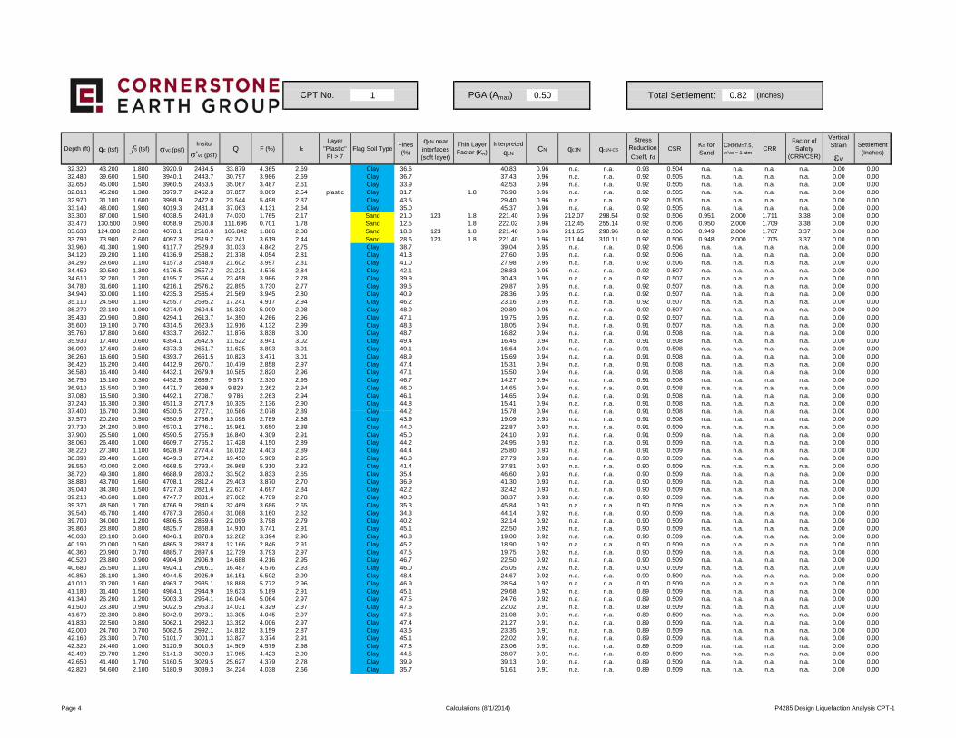
1 0.50 Total Settlement: 0.82 (Inches)
Depth (ft) qc (tsf) fs (tsf) σvc (psf)Insitu
σ'vc (psf)Q F (%) Ic
Layer "Plastic"PI > 7
Flag Soil TypeFines (%)
qcN near interfaces (soft layer)
Thin Layer Factor (KH)
Interpreted
qcNCN qc1N qc1N-CS
Stress Reduction
Coeff, rd
CSRKσ for Sand
CRRM=7.5,
σ'vc = 1 atmCRR
Factor of Safety
(CRR/CSR)
Vertical Strain
εv
Settlement (Inches)
CPT No. PGA (Amax)
32.320 43.200 1.800 3920.9 2434.5 33.879 4.365 2.69 Clay 36.6 40.83 0.96 n.a. n.a. 0.93 0.504 n.a. n.a. n.a. n.a. 0.00 0.0032.480 39.600 1.500 3940.1 2443.7 30.797 3.986 2.69 Clay 36.7 37.43 0.96 n.a. n.a. 0.92 0.505 n.a. n.a. n.a. n.a. 0.00 0.0032.650 45.000 1.500 3960.5 2453.5 35.067 3.487 2.61 Clay 33.9 42.53 0.96 n.a. n.a. 0.92 0.505 n.a. n.a. n.a. n.a. 0.00 0.0032.810 45.200 1.300 3979.7 2462.8 37.857 3.009 2.54 plastic Clay 31.7 1.8 76.90 0.96 n.a. n.a. 0.92 0.505 n.a. n.a. n.a. n.a. 0.00 0.0032.970 31.100 1.600 3998.9 2472.0 23.544 5.498 2.87 Clay 43.5 29.40 0.96 n.a. n.a. 0.92 0.505 n.a. n.a. n.a. n.a. 0.00 0.0033.140 48.000 1.900 4019.3 2481.8 37.063 4.131 2.64 Clay 35.0 45.37 0.96 n.a. n.a. 0.92 0.505 n.a. n.a. n.a. n.a. 0.00 0.0033.300 87.000 1.500 4038.5 2491.0 74.030 1.765 2.17 Sand 21.0 123 1.8 221.40 0.96 212.07 298.54 0.92 0.506 0.951 2.000 1.711 3.38 0.00 0.0033.470 130.500 0.900 4058.9 2500.8 111.696 0.701 1.78 Sand 12.5 1.8 222.02 0.96 212.45 255.14 0.92 0.506 0.950 2.000 1.709 3.38 0.00 0.0033.630 124.000 2.300 4078.1 2510.0 105.842 1.886 2.08 Sand 18.8 123 1.8 221.40 0.96 211.65 290.96 0.92 0.506 0.949 2.000 1.707 3.37 0.00 0.0033.790 73.900 2.600 4097.3 2519.2 62.241 3.619 2.44 Sand 28.6 123 1.8 221.40 0.96 211.44 310.11 0.92 0.506 0.948 2.000 1.705 3.37 0.00 0.0033.960 41.300 1.900 4117.7 2529.0 31.033 4.842 2.75 Clay 38.7 39.04 0.95 n.a. n.a. 0.92 0.506 n.a. n.a. n.a. n.a. 0.00 0.0034.120 29.200 1.100 4136.9 2538.2 21.378 4.054 2.81 Clay 41.3 27.60 0.95 n.a. n.a. 0.92 0.506 n.a. n.a. n.a. n.a. 0.00 0.0034.290 29.600 1.100 4157.3 2548.0 21.602 3.997 2.81 Clay 41.0 27.98 0.95 n.a. n.a. 0.92 0.506 n.a. n.a. n.a. n.a. 0.00 0.0034.450 30.500 1.300 4176.5 2557.2 22.221 4.576 2.84 Clay 42.1 28.83 0.95 n.a. n.a. 0.92 0.507 n.a. n.a. n.a. n.a. 0.00 0.0034.610 32.200 1.200 4195.7 2566.4 23.458 3.986 2.78 Clay 39.9 30.43 0.95 n.a. n.a. 0.92 0.507 n.a. n.a. n.a. n.a. 0.00 0.0034.780 31.600 1.100 4216.1 2576.2 22.895 3.730 2.77 Clay 39.5 29.87 0.95 n.a. n.a. 0.92 0.507 n.a. n.a. n.a. n.a. 0.00 0.0034.940 30.000 1.100 4235.3 2585.4 21.569 3.945 2.80 Clay 40.9 28.36 0.95 n.a. n.a. 0.92 0.507 n.a. n.a. n.a. n.a. 0.00 0.0035.110 24.500 1.100 4255.7 2595.2 17.241 4.917 2.94 Clay 46.2 23.16 0.95 n.a. n.a. 0.92 0.507 n.a. n.a. n.a. n.a. 0.00 0.0035.270 22.100 1.000 4274.9 2604.5 15.330 5.009 2.98 Clay 48.0 20.89 0.95 n.a. n.a. 0.92 0.507 n.a. n.a. n.a. n.a. 0.00 0.0035.430 20.900 0.800 4294.1 2613.7 14.350 4.266 2.96 Clay 47.1 19.75 0.95 n.a. n.a. 0.92 0.507 n.a. n.a. n.a. n.a. 0.00 0.0035.600 19.100 0.700 4314.5 2623.5 12.916 4.132 2.99 Clay 48.3 18.05 0.94 n.a. n.a. 0.91 0.507 n.a. n.a. n.a. n.a. 0.00 0.0035.760 17.800 0.600 4333.7 2632.7 11.876 3.838 3.00 Clay 48.7 16.82 0.94 n.a. n.a. 0.91 0.508 n.a. n.a. n.a. n.a. 0.00 0.0035.930 17.400 0.600 4354.1 2642.5 11.522 3.941 3.02 Clay 49.4 16.45 0.94 n.a. n.a. 0.91 0.508 n.a. n.a. n.a. n.a. 0.00 0.0036.090 17.600 0.600 4373.3 2651.7 11.625 3.893 3.01 Clay 49.1 16.64 0.94 n.a. n.a. 0.91 0.508 n.a. n.a. n.a. n.a. 0.00 0.0036.260 16.600 0.500 4393.7 2661.5 10.823 3.471 3.01 Clay 48.9 15.69 0.94 n.a. n.a. 0.91 0.508 n.a. n.a. n.a. n.a. 0.00 0.0036.420 16.200 0.400 4412.9 2670.7 10.479 2.858 2.97 Clay 47.4 15.31 0.94 n.a. n.a. 0.91 0.508 n.a. n.a. n.a. n.a. 0.00 0.0036.580 16.400 0.400 4432.1 2679.9 10.585 2.820 2.96 Clay 47.1 15.50 0.94 n.a. n.a. 0.91 0.508 n.a. n.a. n.a. n.a. 0.00 0.0036.750 15.100 0.300 4452.5 2689.7 9.573 2.330 2.95 Clay 46.7 14.27 0.94 n.a. n.a. 0.91 0.508 n.a. n.a. n.a. n.a. 0.00 0.0036.910 15.500 0.300 4471.7 2698.9 9.829 2.262 2.94 Clay 46.0 14.65 0.94 n.a. n.a. 0.91 0.508 n.a. n.a. n.a. n.a. 0.00 0.0037.080 15.500 0.300 4492.1 2708.7 9.786 2.263 2.94 Clay 46.1 14.65 0.94 n.a. n.a. 0.91 0.508 n.a. n.a. n.a. n.a. 0.00 0.0037.240 16.300 0.300 4511.3 2717.9 10.335 2.136 2.90 Clay 44.8 15.41 0.94 n.a. n.a. 0.91 0.508 n.a. n.a. n.a. n.a. 0.00 0.0037 400 16 700 0 300 4530 5 2727 1 10 586 2 078 2 89 Clay 44 2 15 78 0 94 n a n a 0 91 0 508 n a n a n a n a 0 00 0 0037.400 16.700 0.300 4530.5 2727.1 10.586 2.078 2.89 Clay 44.2 15.78 0.94 n.a. n.a. 0.91 0.508 n.a. n.a. n.a. n.a. 0.00 0.0037.570 20.200 0.500 4550.9 2736.9 13.098 2.789 2.88 Clay 43.9 19.09 0.93 n.a. n.a. 0.91 0.508 n.a. n.a. n.a. n.a. 0.00 0.0037.730 24.200 0.800 4570.1 2746.1 15.961 3.650 2.88 Clay 44.0 22.87 0.93 n.a. n.a. 0.91 0.509 n.a. n.a. n.a. n.a. 0.00 0.0037.900 25.500 1.000 4590.5 2755.9 16.840 4.309 2.91 Clay 45.0 24.10 0.93 n.a. n.a. 0.91 0.509 n.a. n.a. n.a. n.a. 0.00 0.0038.060 26.400 1.000 4609.7 2765.2 17.428 4.150 2.89 Clay 44.2 24.95 0.93 n.a. n.a. 0.91 0.509 n.a. n.a. n.a. n.a. 0.00 0.0038.220 27.300 1.100 4628.9 2774.4 18.012 4.403 2.89 Clay 44.4 25.80 0.93 n.a. n.a. 0.91 0.509 n.a. n.a. n.a. n.a. 0.00 0.0038.390 29.400 1.600 4649.3 2784.2 19.450 5.909 2.95 Clay 46.8 27.79 0.93 n.a. n.a. 0.90 0.509 n.a. n.a. n.a. n.a. 0.00 0.0038.550 40.000 2.000 4668.5 2793.4 26.968 5.310 2.82 Clay 41.4 37.81 0.93 n.a. n.a. 0.90 0.509 n.a. n.a. n.a. n.a. 0.00 0.0038.720 49.300 1.800 4688.9 2803.2 33.502 3.833 2.65 Clay 35.4 46.60 0.93 n.a. n.a. 0.90 0.509 n.a. n.a. n.a. n.a. 0.00 0.0038.880 43.700 1.600 4708.1 2812.4 29.403 3.870 2.70 Clay 36.9 41.30 0.93 n.a. n.a. 0.90 0.509 n.a. n.a. n.a. n.a. 0.00 0.0039.040 34.300 1.500 4727.3 2821.6 22.637 4.697 2.84 Clay 42.2 32.42 0.93 n.a. n.a. 0.90 0.509 n.a. n.a. n.a. n.a. 0.00 0.0039.210 40.600 1.800 4747.7 2831.4 27.002 4.709 2.78 Clay 40.0 38.37 0.93 n.a. n.a. 0.90 0.509 n.a. n.a. n.a. n.a. 0.00 0.0039.370 48.500 1.700 4766.9 2840.6 32.469 3.686 2.65 Clay 35.3 45.84 0.93 n.a. n.a. 0.90 0.509 n.a. n.a. n.a. n.a. 0.00 0.0039.540 46.700 1.400 4787.3 2850.4 31.088 3.160 2.62 Clay 34.3 44.14 0.92 n.a. n.a. 0.90 0.509 n.a. n.a. n.a. n.a. 0.00 0.0039.700 34.000 1.200 4806.5 2859.6 22.099 3.798 2.79 Clay 40.2 32.14 0.92 n.a. n.a. 0.90 0.509 n.a. n.a. n.a. n.a. 0.00 0.0039.860 23.800 0.800 4825.7 2868.8 14.910 3.741 2.91 Clay 45.1 22.50 0.92 n.a. n.a. 0.90 0.509 n.a. n.a. n.a. n.a. 0.00 0.0040.030 20.100 0.600 4846.1 2878.6 12.282 3.394 2.96 Clay 46.8 19.00 0.92 n.a. n.a. 0.90 0.509 n.a. n.a. n.a. n.a. 0.00 0.0040.190 20.000 0.500 4865.3 2887.8 12.166 2.846 2.91 Clay 45.2 18.90 0.92 n.a. n.a. 0.90 0.509 n.a. n.a. n.a. n.a. 0.00 0.0040.360 20.900 0.700 4885.7 2897.6 12.739 3.793 2.97 Clay 47.5 19.75 0.92 n.a. n.a. 0.90 0.509 n.a. n.a. n.a. n.a. 0.00 0.0040.520 23.800 0.900 4904.9 2906.9 14.688 4.216 2.95 Clay 46.7 22.50 0.92 n.a. n.a. 0.90 0.509 n.a. n.a. n.a. n.a. 0.00 0.0040.680 26.500 1.100 4924.1 2916.1 16.487 4.576 2.93 Clay 46.0 25.05 0.92 n.a. n.a. 0.90 0.509 n.a. n.a. n.a. n.a. 0.00 0.0040.850 26.100 1.300 4944.5 2925.9 16.151 5.502 2.99 Clay 48.4 24.67 0.92 n.a. n.a. 0.90 0.509 n.a. n.a. n.a. n.a. 0.00 0.0041.010 30.200 1.600 4963.7 2935.1 18.888 5.772 2.96 Clay 46.9 28.54 0.92 n.a. n.a. 0.90 0.509 n.a. n.a. n.a. n.a. 0.00 0.0041.180 31.400 1.500 4984.1 2944.9 19.633 5.189 2.91 Clay 45.1 29.68 0.92 n.a. n.a. 0.89 0.509 n.a. n.a. n.a. n.a. 0.00 0.0041.340 26.200 1.200 5003.3 2954.1 16.044 5.064 2.97 Clay 47.5 24.76 0.92 n.a. n.a. 0.89 0.509 n.a. n.a. n.a. n.a. 0.00 0.0041.500 23.300 0.900 5022.5 2963.3 14.031 4.329 2.97 Clay 47.6 22.02 0.91 n.a. n.a. 0.89 0.509 n.a. n.a. n.a. n.a. 0.00 0.0041.670 22.300 0.800 5042.9 2973.1 13.305 4.045 2.97 Clay 47.6 21.08 0.91 n.a. n.a. 0.89 0.509 n.a. n.a. n.a. n.a. 0.00 0.0041.830 22.500 0.800 5062.1 2982.3 13.392 4.006 2.97 Clay 47.4 21.27 0.91 n.a. n.a. 0.89 0.509 n.a. n.a. n.a. n.a. 0.00 0.0042.000 24.700 0.700 5082.5 2992.1 14.812 3.159 2.87 Clay 43.5 23.35 0.91 n.a. n.a. 0.89 0.509 n.a. n.a. n.a. n.a. 0.00 0.0042.160 23.300 0.700 5101.7 3001.3 13.827 3.374 2.91 Clay 45.1 22.02 0.91 n.a. n.a. 0.89 0.509 n.a. n.a. n.a. n.a. 0.00 0.0042.320 24.400 1.000 5120.9 3010.5 14.509 4.579 2.98 Clay 47.8 23.06 0.91 n.a. n.a. 0.89 0.509 n.a. n.a. n.a. n.a. 0.00 0.0042.490 29.700 1.200 5141.3 3020.3 17.965 4.423 2.90 Clay 44.5 28.07 0.91 n.a. n.a. 0.89 0.509 n.a. n.a. n.a. n.a. 0.00 0.0042.650 41.400 1.700 5160.5 3029.5 25.627 4.379 2.78 Clay 39.9 39.13 0.91 n.a. n.a. 0.89 0.509 n.a. n.a. n.a. n.a. 0.00 0.0042.820 54.600 2.100 5180.9 3039.3 34.224 4.038 2.66 Clay 35.7 51.61 0.91 n.a. n.a. 0.89 0.509 n.a. n.a. n.a. n.a. 0.00 0.00
Page 4 Calculations (8/1/2014) P4285 Design Liquefaction Analysis CPT-1
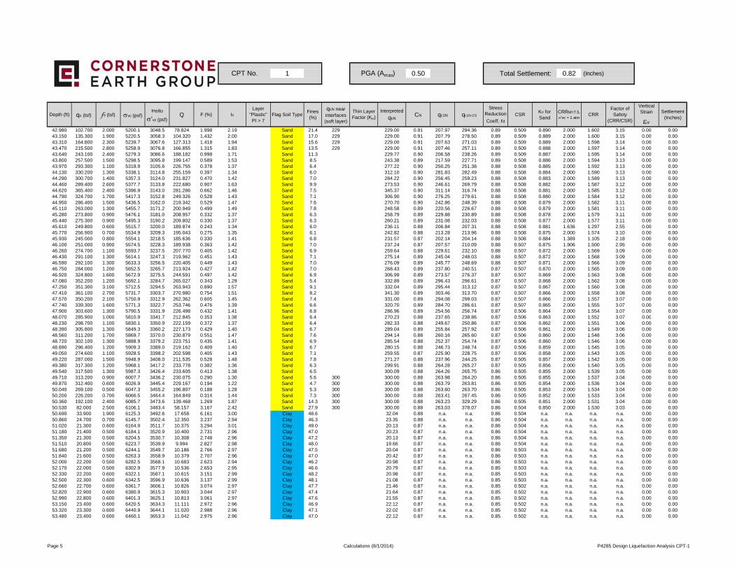
1 0.50 Total Settlement: 0.82 (Inches)
Depth (ft) qc (tsf) fs (tsf) σvc (psf)Insitu
σ'vc (psf)Q F (%) Ic
Layer "Plastic"PI > 7
Flag Soil TypeFines (%)
qcN near interfaces (soft layer)
Thin Layer Factor (KH)
Interpreted
qcNCN qc1N qc1N-CS
Stress Reduction
Coeff, rd
CSRKσ for Sand
CRRM=7.5,
σ'vc = 1 atmCRR
Factor of Safety
(CRR/CSR)
Vertical Strain
εv
Settlement (Inches)
CPT No. PGA (Amax)
42.980 102.700 2.000 5200.1 3048.5 78.824 1.998 2.19 Sand 21.4 229 229.00 0.91 207.97 294.36 0.89 0.509 0.890 2.000 1.602 3.15 0.00 0.0043.150 135.300 1.900 5220.5 3058.3 104.320 1.432 2.00 Sand 17.0 229 229.00 0.91 207.79 278.50 0.89 0.509 0.889 2.000 1.600 3.15 0.00 0.0043.310 164.800 2.300 5239.7 3067.6 127.313 1.418 1.94 Sand 15.6 229 229.00 0.91 207.63 271.03 0.89 0.509 0.889 2.000 1.598 3.14 0.00 0.0043.470 215.500 2.800 5258.9 3076.8 166.855 1.315 1.83 Sand 13.5 229 229.00 0.91 207.46 257.11 0.89 0.509 0.888 2.000 1.597 3.14 0.00 0.0043.640 243.100 2.400 5279.3 3086.6 188.182 0.998 1.71 Sand 11.3 229.77 0.90 206.58 238.26 0.89 0.509 0.887 2.000 1.595 3.14 0.00 0.0043.800 257.500 1.500 5298.5 3095.8 199.147 0.589 1.53 Sand 8.5 243.38 0.89 217.59 227.71 0.89 0.508 0.886 2.000 1.594 3.13 0.00 0.0043.970 293.300 1.100 5318.9 3105.6 226.755 0.378 1.37 Sand 6.4 277.22 0.90 250.25 251.38 0.88 0.508 0.885 2.000 1.592 3.13 0.00 0.0044.130 330.200 1.300 5338.1 3114.8 255.159 0.397 1.34 Sand 6.0 312.10 0.90 281.83 282.49 0.88 0.508 0.884 2.000 1.590 3.13 0.00 0.0044.290 300.700 1.400 5357.3 3124.0 231.827 0.470 1.42 Sand 7.0 284.22 0.90 256.45 259.23 0.88 0.508 0.883 2.000 1.589 3.13 0.00 0.0044.460 289.400 2.600 5377.7 3133.8 222.680 0.907 1.63 Sand 9.9 273.53 0.90 246.61 269.79 0.88 0.508 0.882 2.000 1.587 3.12 0.00 0.0044.620 365.400 2.400 5396.9 3143.0 281.286 0.662 1.46 Sand 7.5 345.37 0.90 311.14 316.74 0.88 0.508 0.881 2.000 1.585 3.12 0.00 0.0044.790 324.700 1.700 5417.3 3152.8 249.326 0.528 1.43 Sand 7.1 306.90 0.90 276.25 279.61 0.88 0.508 0.880 2.000 1.584 3.12 0.00 0.0044.950 286.400 1.500 5436.5 3162.0 219.342 0.529 1.47 Sand 7.6 270.70 0.90 242.86 248.39 0.88 0.508 0.879 2.000 1.582 3.11 0.00 0.0045.110 263.000 1.300 5455.7 3171.2 200.949 0.499 1.49 Sand 7.8 248.58 0.89 220.56 226.67 0.88 0.508 0.879 2.000 1.581 3.11 0.00 0.0045.280 273.800 0.900 5476.1 3181.0 208.957 0.332 1.37 Sand 6.3 258.79 0.89 229.88 230.89 0.88 0.508 0.878 2.000 1.579 3.11 0.00 0.0045.440 275.300 0.900 5495.3 3190.2 209.802 0.330 1.37 Sand 6.3 260.21 0.89 231.08 232.03 0.88 0.508 0.877 2.000 1.577 3.11 0.00 0.0045.610 249.800 0.600 5515.7 3200.0 189.874 0.243 1.34 Sand 6.0 236.11 0.88 206.84 207.31 0.88 0.508 0.881 1.636 1.297 2.55 0.00 0.0045.770 256.900 0.700 5534.9 3209.3 195.043 0.275 1.35 Sand 6.1 242.82 0.88 213.28 213.96 0.88 0.508 0.875 2.000 1.574 3.10 0.00 0.0045.930 245.000 0.800 5554.1 3218.5 185.636 0.330 1.41 Sand 6.8 231.57 0.87 202.14 204.14 0.88 0.508 0.884 1.389 1.105 2.18 0.00 0.0046.100 251.000 0.900 5574.5 3228.3 189.938 0.363 1.42 Sand 7.0 237.24 0.87 207.57 210.09 0.88 0.507 0.875 1.906 1.500 2.95 0.00 0.0046.260 274.700 1.100 5593.7 3237.5 207.770 0.405 1.42 Sand 6.9 259.64 0.88 229.61 232.10 0.88 0.507 0.872 2.000 1.569 3.09 0.00 0.0046.430 291.100 1.300 5614.1 3247.3 219.962 0.451 1.43 Sand 7.1 275.14 0.89 245.04 248.03 0.88 0.507 0.872 2.000 1.568 3.09 0.00 0.0046.590 292.100 1.300 5633.3 3256.5 220.405 0.449 1.43 Sand 7.0 276.09 0.89 245.77 248.69 0.88 0.507 0.871 2.000 1.566 3.09 0.00 0.0046.750 284.000 1.200 5652.5 3265.7 213.924 0.427 1.42 Sand 7.0 268.43 0.89 237.80 240.51 0.87 0.507 0.870 2.000 1.565 3.09 0.00 0.0046.920 324.800 1.600 5672.9 3275.5 244.591 0.497 1.42 Sand 6.9 306.99 0.89 273.57 276.37 0.87 0.507 0.869 2.000 1.563 3.08 0.00 0.0047.080 352.200 1.200 5692.1 3284.7 265.027 0.343 1.29 Sand 5.4 332.89 0.89 296.43 296.61 0.87 0.507 0.868 2.000 1.562 3.08 0.00 0.0047.250 351.300 3.100 5712.5 3294.5 263.943 0.890 1.57 Sand 9.1 332.04 0.89 295.44 313.12 0.87 0.507 0.867 2.000 1.560 3.08 0.00 0.0047.410 361.100 2.700 5731.7 3303.7 270.980 0.754 1.51 Sand 8.2 341.30 0.89 303.46 313.70 0.87 0.507 0.866 2.000 1.558 3.08 0.00 0.0047.570 350.200 2.100 5750.9 3312.9 262.362 0.605 1.45 Sand 7.4 331.00 0.89 294.08 299.03 0.87 0.507 0.866 2.000 1.557 3.07 0.00 0.0047.740 339.300 1.600 5771.3 3322.7 253.746 0.476 1.39 Sand 6.6 320.70 0.89 284.70 286.61 0.87 0.507 0.865 2.000 1.555 3.07 0.00 0.0047.900 303.600 1.300 5790.5 3331.9 226.498 0.432 1.41 Sand 6.8 286.96 0.89 254.56 256.74 0.87 0.506 0.864 2.000 1.554 3.07 0.00 0.0048 070 285 900 1 000 5810 9 3341 7 212 845 0 353 1 38 Sand 6 4 270 23 0 88 237 65 238 86 0 87 0 506 0 863 2 000 1 552 3 07 0 00 0 0048.070 285.900 1.000 5810.9 3341.7 212.845 0.353 1.38 Sand 6.4 270.23 0.88 237.65 238.86 0.87 0.506 0.863 2.000 1.552 3.07 0.00 0.0048.230 298.700 1.100 5830.1 3350.9 222.159 0.372 1.37 Sand 6.4 282.33 0.88 249.67 250.86 0.87 0.506 0.862 2.000 1.551 3.06 0.00 0.0048.390 305.800 1.300 5849.3 3360.2 227.173 0.429 1.40 Sand 6.7 289.04 0.89 255.84 257.92 0.87 0.506 0.861 2.000 1.549 3.06 0.00 0.0048.560 311.200 1.700 5869.7 3370.0 230.879 0.551 1.47 Sand 7.6 294.14 0.88 260.16 265.60 0.87 0.506 0.860 2.000 1.548 3.06 0.00 0.0048.720 302.100 1.300 5888.9 3379.2 223.751 0.435 1.41 Sand 6.9 285.54 0.88 252.37 254.74 0.87 0.506 0.860 2.000 1.546 3.06 0.00 0.0048.890 296.400 1.200 5909.3 3389.0 219.162 0.409 1.40 Sand 6.7 280.15 0.88 246.73 248.74 0.87 0.506 0.859 2.000 1.545 3.05 0.00 0.0049.050 274.600 1.100 5928.5 3398.2 202.598 0.405 1.43 Sand 7.1 259.55 0.87 225.90 228.75 0.87 0.506 0.858 2.000 1.543 3.05 0.00 0.0049.220 287.000 1.500 5948.9 3408.0 211.535 0.528 1.48 Sand 7.8 271.27 0.88 237.96 244.25 0.87 0.505 0.857 2.000 1.542 3.05 0.00 0.0049.380 317.300 1.200 5968.1 3417.2 233.778 0.382 1.36 Sand 6.3 299.91 0.88 264.28 265.27 0.87 0.505 0.856 2.000 1.540 3.05 0.00 0.0049.540 317.500 1.300 5987.3 3426.4 233.605 0.413 1.38 Sand 6.5 300.09 0.88 264.26 265.75 0.86 0.505 0.855 2.000 1.539 3.05 0.00 0.0049.710 313.200 0.900 6007.7 3436.2 230.075 0.290 1.30 Sand 5.6 300 300.00 0.88 263.98 264.20 0.86 0.505 0.855 2.000 1.537 3.04 0.00 0.0049.870 312.400 0.600 6026.9 3445.4 229.167 0.194 1.22 Sand 4.7 300 300.00 0.88 263.79 263.81 0.86 0.505 0.854 2.000 1.536 3.04 0.00 0.0050.040 269.100 0.500 6047.3 3455.2 196.807 0.188 1.28 Sand 5.3 300 300.00 0.88 263.60 263.70 0.86 0.505 0.853 2.000 1.534 3.04 0.00 0.0050.200 226.200 0.700 6066.5 3464.4 164.849 0.314 1.44 Sand 7.3 300 300.00 0.88 263.41 267.45 0.86 0.505 0.852 2.000 1.533 3.04 0.00 0.0050.360 192.100 2.400 6085.7 3473.6 139.468 1.269 1.87 Sand 14.3 300 300.00 0.88 263.23 329.29 0.86 0.505 0.851 2.000 1.531 3.04 0.00 0.0050.530 82.000 2.500 6106.1 3483.4 58.157 3.167 2.42 Sand 27.9 300 300.00 0.88 263.03 378.07 0.86 0.504 0.850 2.000 1.530 3.03 0.00 0.0050.690 33.900 1.900 6125.3 3492.6 17.658 6.161 3.00 Clay 48.6 32.04 0.88 n.a. n.a. 0.86 0.504 n.a. n.a. n.a. n.a. 0.00 0.0050.860 24.700 0.700 6145.7 3502.4 12.350 3.237 2.94 Clay 46.3 23.35 0.88 n.a. n.a. 0.86 0.504 n.a. n.a. n.a. n.a. 0.00 0.0051.020 21.300 0.600 6164.9 3511.7 10.375 3.294 3.01 Clay 49.0 20.13 0.87 n.a. n.a. 0.86 0.504 n.a. n.a. n.a. n.a. 0.00 0.0051.180 21.400 0.500 6184.1 3520.9 10.400 2.731 2.96 Clay 47.0 20.23 0.87 n.a. n.a. 0.86 0.504 n.a. n.a. n.a. n.a. 0.00 0.0051.350 21.300 0.500 6204.5 3530.7 10.308 2.748 2.96 Clay 47.2 20.13 0.87 n.a. n.a. 0.86 0.504 n.a. n.a. n.a. n.a. 0.00 0.0051.510 20.800 0.500 6223.7 3539.9 9.994 2.827 2.98 Clay 48.0 19.66 0.87 n.a. n.a. 0.86 0.504 n.a. n.a. n.a. n.a. 0.00 0.0051.680 21.200 0.500 6244.1 3549.7 10.186 2.766 2.97 Clay 47.5 20.04 0.87 n.a. n.a. 0.86 0.503 n.a. n.a. n.a. n.a. 0.00 0.0051.840 21.600 0.500 6263.3 3558.9 10.379 2.707 2.96 Clay 47.0 20.42 0.87 n.a. n.a. 0.86 0.503 n.a. n.a. n.a. n.a. 0.00 0.0052.000 22.200 0.500 6282.5 3568.1 10.683 2.623 2.94 Clay 46.2 20.98 0.87 n.a. n.a. 0.86 0.503 n.a. n.a. n.a. n.a. 0.00 0.0052.170 22.000 0.500 6302.9 3577.9 10.536 2.653 2.95 Clay 46.6 20.79 0.87 n.a. n.a. 0.85 0.503 n.a. n.a. n.a. n.a. 0.00 0.0052.330 22.200 0.600 6322.1 3587.1 10.615 3.151 2.99 Clay 48.2 20.98 0.87 n.a. n.a. 0.85 0.503 n.a. n.a. n.a. n.a. 0.00 0.0052.500 22.300 0.600 6342.5 3596.9 10.636 3.137 2.99 Clay 48.1 21.08 0.87 n.a. n.a. 0.85 0.503 n.a. n.a. n.a. n.a. 0.00 0.0052.660 22.700 0.600 6361.7 3606.1 10.826 3.074 2.97 Clay 47.7 21.46 0.87 n.a. n.a. 0.85 0.502 n.a. n.a. n.a. n.a. 0.00 0.0052.820 22.900 0.600 6380.9 3615.3 10.903 3.044 2.97 Clay 47.4 21.64 0.87 n.a. n.a. 0.85 0.502 n.a. n.a. n.a. n.a. 0.00 0.0052.990 22.800 0.600 6401.3 3625.1 10.813 3.061 2.97 Clay 47.6 21.55 0.87 n.a. n.a. 0.85 0.502 n.a. n.a. n.a. n.a. 0.00 0.0053.150 23.400 0.600 6420.5 3634.3 11.111 2.972 2.96 Clay 46.9 22.12 0.87 n.a. n.a. 0.85 0.502 n.a. n.a. n.a. n.a. 0.00 0.0053.320 23.300 0.600 6440.9 3644.1 11.020 2.988 2.96 Clay 47.1 22.02 0.87 n.a. n.a. 0.85 0.502 n.a. n.a. n.a. n.a. 0.00 0.0053.480 23.400 0.600 6460.1 3653.3 11.042 2.975 2.96 Clay 47.0 22.12 0.87 n.a. n.a. 0.85 0.502 n.a. n.a. n.a. n.a. 0.00 0.00
Page 5 Calculations (8/1/2014) P4285 Design Liquefaction Analysis CPT-1
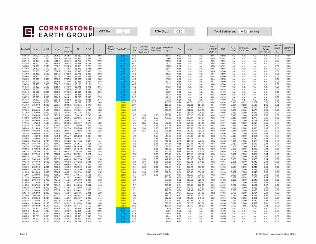
1 0.50 Total Settlement: 0.82 (Inches)
Depth (ft) qc (tsf) fs (tsf) σvc (psf)Insitu
σ'vc (psf)Q F (%) Ic
Layer "Plastic"PI > 7
Flag Soil TypeFines (%)
qcN near interfaces (soft layer)
Thin Layer Factor (KH)
Interpreted
qcNCN qc1N qc1N-CS
Stress Reduction
Coeff, rd
CSRKσ for Sand
CRRM=7.5,
σ'vc = 1 atmCRR
Factor of Safety
(CRR/CSR)
Vertical Strain
εv
Settlement (Inches)
CPT No. PGA (Amax)
53.640 24.500 0.600 6479.3 3662.6 11.610 2.822 2.93 Clay 45.8 23.16 0.87 n.a. n.a. 0.85 0.502 n.a. n.a. n.a. n.a. 0.00 0.0053.810 24.400 0.600 6499.7 3672.4 11.519 2.837 2.93 Clay 45.9 23.06 0.86 n.a. n.a. 0.85 0.501 n.a. n.a. n.a. n.a. 0.00 0.0053.970 24.900 0.600 6518.9 3681.6 11.756 2.773 2.92 Clay 45.4 23.53 0.86 n.a. n.a. 0.85 0.501 n.a. n.a. n.a. n.a. 0.00 0.0054.140 25.100 0.600 6539.3 3691.4 11.828 2.748 2.92 Clay 45.2 23.72 0.86 n.a. n.a. 0.85 0.501 n.a. n.a. n.a. n.a. 0.00 0.0054.300 24.900 0.600 6558.5 3700.6 11.685 2.775 2.92 Clay 45.5 23.53 0.86 n.a. n.a. 0.85 0.501 n.a. n.a. n.a. n.a. 0.00 0.0054.460 24.200 0.500 6577.7 3709.8 11.273 2.391 2.90 Clay 44.6 22.87 0.86 n.a. n.a. 0.85 0.501 n.a. n.a. n.a. n.a. 0.00 0.0054.630 23.600 0.500 6598.1 3719.6 10.916 2.463 2.92 Clay 45.3 22.31 0.86 n.a. n.a. 0.85 0.500 n.a. n.a. n.a. n.a. 0.00 0.0054.790 23.400 0.500 6617.3 3728.8 10.776 2.489 2.92 Clay 45.6 22.12 0.86 n.a. n.a. 0.84 0.500 n.a. n.a. n.a. n.a. 0.00 0.0054.960 24.300 0.500 6637.7 3738.6 11.224 2.383 2.90 Clay 44.6 22.97 0.86 n.a. n.a. 0.84 0.500 n.a. n.a. n.a. n.a. 0.00 0.0055.120 23.800 0.400 6656.9 3747.8 10.925 1.954 2.86 Clay 43.1 22.50 0.86 n.a. n.a. 0.84 0.500 n.a. n.a. n.a. n.a. 0.00 0.0055.280 23.000 0.400 6676.1 3757.0 10.467 2.034 2.89 Clay 44.1 21.74 0.86 n.a. n.a. 0.84 0.500 n.a. n.a. n.a. n.a. 0.00 0.0055.450 22.400 0.400 6696.5 3766.8 10.116 2.100 2.91 Clay 44.9 21.17 0.86 n.a. n.a. 0.84 0.500 n.a. n.a. n.a. n.a. 0.00 0.0055.610 27.800 0.500 6715.7 3776.0 12.946 2.046 2.81 Clay 41.1 26.28 0.86 n.a. n.a. 0.84 0.499 n.a. n.a. n.a. n.a. 0.00 0.0055.780 32.000 0.600 6736.1 3785.8 15.126 2.096 2.76 Clay 39.2 30.25 0.86 n.a. n.a. 0.84 0.499 n.a. n.a. n.a. n.a. 0.00 0.0055.940 33.100 0.800 6755.3 3795.0 15.664 2.692 2.81 Clay 41.1 31.29 0.86 n.a. n.a. 0.84 0.499 n.a. n.a. n.a. n.a. 0.00 0.0056.110 38.300 1.000 6775.7 3804.8 18.351 2.864 2.77 Clay 39.6 36.20 0.86 n.a. n.a. 0.84 0.499 n.a. n.a. n.a. n.a. 0.00 0.0056.270 45.800 1.500 6794.9 3814.1 22.235 3.538 2.76 Clay 39.3 43.29 0.86 n.a. n.a. 0.84 0.499 n.a. n.a. n.a. n.a. 0.00 0.0056.430 54.200 2.200 6814.1 3823.3 26.570 4.331 2.76 Clay 39.3 51.23 0.86 n.a. n.a. 0.84 0.498 n.a. n.a. n.a. n.a. 0.00 0.0056.600 109.900 4.000 6834.5 3833.1 74.779 3.756 2.40 Sand 27.3 103.88 0.78 80.52 135.11 0.84 0.498 0.916 0.217 0.179 0.36 0.02 0.0056.760 165.000 4.000 6853.7 3842.3 113.331 2.476 2.15 Sand 20.4 155.95 0.81 126.81 187.36 0.84 0.498 0.864 0.682 0.530 1.06 0.01 0.0056.930 211.200 3.200 6874.1 3852.1 145.544 1.540 1.92 Sand 15.3 199.62 0.83 166.32 219.31 0.84 0.498 0.820 2.000 1.476 2.96 0.00 0.0057.090 250.600 3.100 6893.3 3861.3 172.931 1.254 1.80 Sand 13.0 236.86 0.85 201.01 246.00 0.84 0.498 0.820 2.000 1.474 2.96 0.00 0.0057.250 234.900 2.800 6912.5 3870.5 161.746 1.210 1.81 Sand 13.2 222.02 0.84 186.17 229.99 0.84 0.498 0.819 2.000 1.473 2.96 0.00 0.0057.420 254.800 2.000 6932.9 3880.3 175.425 0.796 1.66 Sand 10.5 235 1.56 375.70 0.85 320.16 354.90 0.84 0.497 0.818 2.000 1.472 2.96 0.00 0.0057.580 323.300 2.100 6952.1 3889.5 222.965 0.657 1.53 Sand 8.4 235 1.56 476.70 0.85 405.97 421.54 0.83 0.497 0.817 2.000 1.470 2.96 0.00 0.0057.750 407.600 2.000 6972.5 3899.3 281.373 0.495 1.37 Sand 6.4 235 1.56 601.00 0.85 511.49 513.48 0.83 0.497 0.817 2.000 1.469 2.96 0.00 0.0057.910 442.300 2.500 6991.7 3908.5 305.167 0.570 1.39 Sand 6.6 235 1.56 652.16 0.85 554.69 557.61 0.83 0.497 0.816 2.000 1.468 2.95 0.00 0.0058.070 477.800 2.700 7010.9 3917.7 329.460 0.569 1.36 Sand 6.3 235 1.56 704.51 0.85 598.83 600.79 0.83 0.497 0.815 2.000 1.466 2.95 0.00 0.0058.240 521.800 3.000 7031.3 3927.5 359.568 0.579 1.34 Sand 6.0 235 1.56 769.38 0.85 653.55 654.88 0.83 0.496 0.814 2.000 1.465 2.95 0.00 0.0058.400 497.200 2.600 7050.5 3936.7 342.093 0.527 1.33 Sand 5.8 235 1.56 733.11 0.85 622.35 623.25 0.83 0.496 0.814 2.000 1.464 2.95 0.00 0.0058.570 450.500 2.000 7070.9 3946.5 309.341 0.447 1.31 Sand 5.7 1.56 664.25 0.85 563.53 564.06 0.83 0.496 0.813 2.000 1.463 2.95 0.00 0.0058 730 416 200 1 800 7090 1 3955 7 285 263 0 436 1 33 Sand 5 9 1 56 613 68 0 85 520 30 521 12 0 83 0 496 0 812 2 000 1 461 2 95 0 00 0 0058.730 416.200 1.800 7090.1 3955.7 285.263 0.436 1.33 Sand 5.9 1.56 613.68 0.85 520.30 521.12 0.83 0.496 0.812 2.000 1.461 2.95 0.00 0.0058.890 376.000 1.600 7109.3 3965.0 257.167 0.430 1.36 Sand 6.2 1.56 554.40 0.85 469.76 471.27 0.83 0.496 0.812 2.000 1.460 2.95 0.00 0.0059.060 354.100 1.700 7129.7 3974.8 241.740 0.485 1.41 Sand 6.9 1.56 522.11 0.85 442.11 446.04 0.83 0.495 0.811 2.000 1.459 2.94 0.00 0.0059.220 368.700 1.500 7148.9 3984.0 251.511 0.411 1.36 Sand 6.2 1.56 543.64 0.85 460.06 461.40 0.83 0.495 0.810 2.000 1.457 2.94 0.00 0.0059.390 357.500 1.300 7169.3 3993.8 243.490 0.367 1.34 Sand 6.0 1.56 527.13 0.85 445.79 446.67 0.83 0.495 0.809 2.000 1.456 2.94 0.00 0.0059.550 378.800 1.100 7188.5 4003.0 257.840 0.293 1.26 Sand 5.1 1.56 558.53 0.85 472.07 472.17 0.83 0.495 0.809 2.000 1.455 2.94 0.00 0.0059.710 339.200 1.700 7207.7 4012.2 230.355 0.507 1.44 Sand 7.3 1.56 500.14 0.84 422.46 428.29 0.83 0.495 0.808 2.000 1.454 2.94 0.00 0.0059.880 327.900 1.700 7228.1 4022.0 222.321 0.524 1.46 Sand 7.5 1.56 483.48 0.84 408.13 415.72 0.83 0.494 0.807 2.000 1.452 2.94 0.00 0.0060.040 311.700 1.400 7247.3 4031.2 210.966 0.454 1.44 Sand 7.3 1.56 459.60 0.84 387.73 393.19 0.83 0.494 0.807 2.000 1.451 2.94 0.00 0.0060.210 300.100 1.600 7267.7 4041.0 202.770 0.540 1.50 Sand 8.1 239 1.56 442.49 0.84 373.06 384.29 0.82 0.494 0.806 2.000 1.450 2.94 0.00 0.0060.370 257.300 1.500 7286.9 4050.2 173.292 0.591 1.58 Sand 9.2 239 1.56 379.38 0.84 319.66 340.11 0.82 0.494 0.805 2.000 1.449 2.93 0.00 0.0060.530 241.500 1.200 7306.1 4059.4 162.307 0.505 1.56 Sand 8.9 239 1.56 372.84 0.84 313.96 331.17 0.82 0.493 0.805 2.000 1.447 2.93 0.00 0.0060.700 236.900 1.300 7326.5 4069.2 158.969 0.557 1.59 Sand 9.4 239 1.56 372.84 0.84 313.76 336.11 0.82 0.493 0.804 2.000 1.446 2.93 0.00 0.0060.860 240.200 1.000 7345.7 4078.4 161.030 0.423 1.52 Sand 8.3 239 1.56 372.84 0.84 313.57 325.30 0.82 0.493 0.803 2.000 1.445 2.93 0.00 0.0061.030 241.000 1.300 7366.1 4088.2 161.374 0.548 1.58 Sand 9.3 239 1.56 372.84 0.84 313.37 334.12 0.82 0.493 0.802 2.000 1.443 2.93 0.00 0.0061.190 223.900 1.200 7385.3 4097.4 149.571 0.545 1.61 Sand 9.7 239 1.56 372.84 0.84 313.19 338.07 0.82 0.493 0.802 2.000 1.442 2.93 0.00 0.0061.350 244.600 1.100 7404.5 4106.7 163.441 0.457 1.53 Sand 8.5 231.19 0.80 184.80 193.89 0.82 0.492 0.837 0.874 0.658 1.34 0.00 0.0061.520 293.400 0.700 7424.9 4116.5 196.309 0.242 1.32 Sand 5.8 277.32 0.82 228.12 228.48 0.82 0.492 0.800 2.000 1.440 2.93 0.00 0.0061.680 327.800 1.100 7444.1 4125.7 219.369 0.339 1.36 Sand 6.2 309.83 0.84 259.79 260.63 0.82 0.492 0.800 2.000 1.439 2.92 0.00 0.0061.850 323.700 1.700 7464.5 4135.5 216.330 0.531 1.48 Sand 7.7 305.95 0.84 256.38 262.57 0.82 0.492 0.799 2.000 1.437 2.92 0.00 0.0062.010 345.800 1.900 7483.7 4144.7 231.008 0.555 1.47 Sand 7.6 326.84 0.84 273.72 279.52 0.82 0.492 0.798 2.000 1.436 2.92 0.00 0.0062.170 316.000 1.800 7502.9 4153.9 210.642 0.576 1.51 Sand 8.2 298.68 0.84 249.99 258.73 0.82 0.491 0.798 2.000 1.435 2.92 0.00 0.0062.340 335.900 1.300 7523.3 4163.7 223.796 0.391 1.38 Sand 6.5 317.49 0.84 265.56 267.09 0.82 0.491 0.797 2.000 1.434 2.92 0.00 0.0062.500 305.300 1.200 7542.5 4172.9 202.947 0.398 1.42 Sand 7.0 288.56 0.83 238.95 241.70 0.82 0.491 0.796 2.000 1.432 2.92 0.00 0.0062.670 309.800 1.200 7562.9 4182.7 205.727 0.392 1.41 Sand 6.9 292.82 0.83 243.03 245.46 0.82 0.491 0.796 2.000 1.431 2.92 0.00 0.0062.830 318.400 1.100 7582.1 4191.9 211.270 0.350 1.38 Sand 6.4 300.95 0.83 250.93 252.20 0.81 0.490 0.795 2.000 1.430 2.92 0.00 0.0063.000 323.600 2.100 7602.5 4201.7 214.504 0.657 1.54 Sand 8.6 305.86 0.83 255.23 267.38 0.81 0.490 0.794 2.000 1.429 2.91 0.00 0.0063.160 194.500 4.100 7621.7 4210.9 127.764 2.150 2.07 Sand 18.5 183.84 0.80 147.75 209.12 0.81 0.490 0.798 1.805 1.296 2.64 0.00 0.0063.320 83.900 3.600 7640.9 4220.1 37.951 4.496 2.66 Clay 35.7 79.30 0.83 n.a. n.a. 0.81 0.490 n.a. n.a. n.a. n.a. 0.00 0.0063.490 43.600 2.200 7661.3 4229.9 18.804 5.532 2.95 Clay 46.4 41.21 0.83 n.a. n.a. 0.81 0.490 n.a. n.a. n.a. n.a. 0.00 0.0063.650 37.700 1.000 7680.5 4239.1 15.975 2.953 2.83 Clay 41.8 35.63 0.83 n.a. n.a. 0.81 0.489 n.a. n.a. n.a. n.a. 0.00 0.0063.820 41.700 1.000 7700.9 4248.9 17.816 2.642 2.76 Clay 39.2 39.41 0.83 n.a. n.a. 0.81 0.489 n.a. n.a. n.a. n.a. 0.00 0.0063.980 44.100 1.600 7720.1 4258.1 18.900 3.976 2.85 Clay 42.6 41.68 0.83 n.a. n.a. 0.81 0.489 n.a. n.a. n.a. n.a. 0.00 0.0064.140 35.300 1.200 7739.3 4267.4 14.731 3.818 2.92 Clay 45.5 33.36 0.83 n.a. n.a. 0.81 0.489 n.a. n.a. n.a. n.a. 0.00 0.00
Page 6 Calculations (8/1/2014) P4285 Design Liquefaction Analysis CPT-1
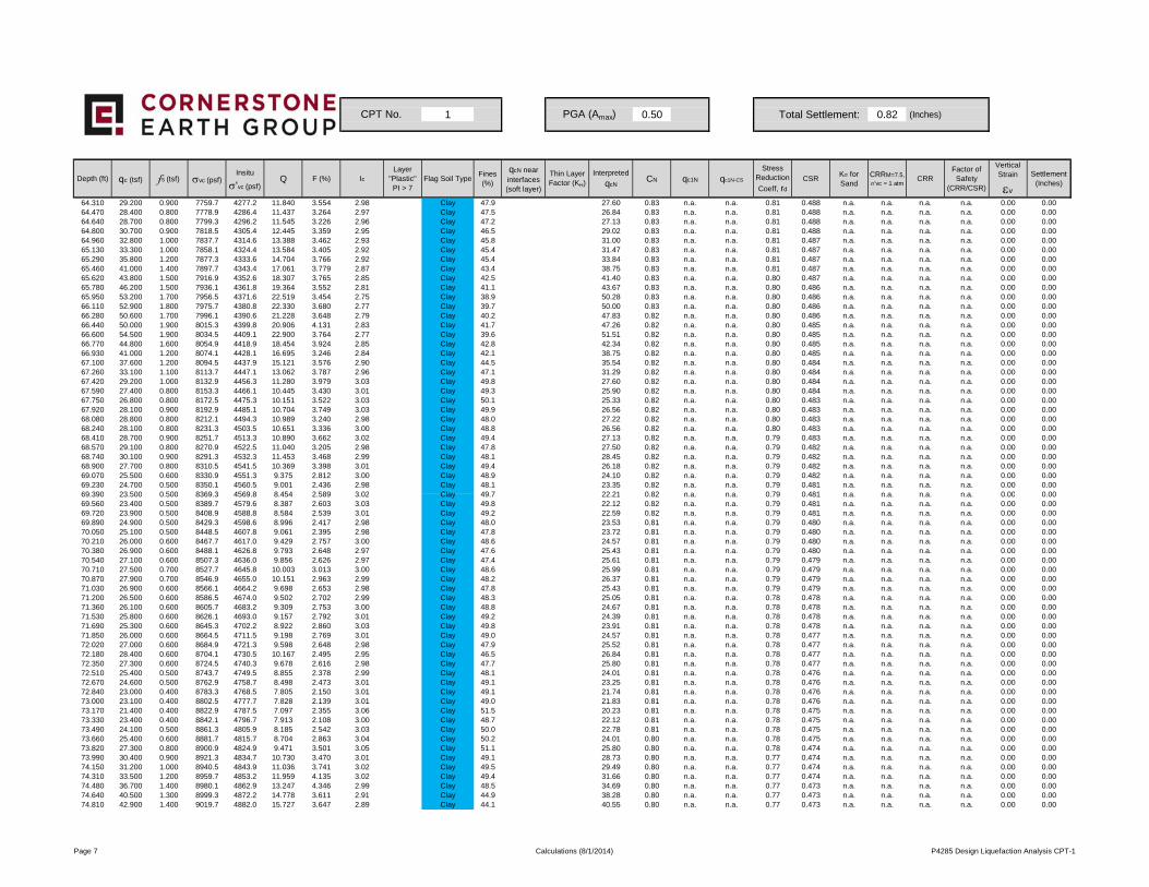
1 0.50 Total Settlement: 0.82 (Inches)
Depth (ft) qc (tsf) fs (tsf) σvc (psf)Insitu
σ'vc (psf)Q F (%) Ic
Layer "Plastic"PI > 7
Flag Soil TypeFines (%)
qcN near interfaces (soft layer)
Thin Layer Factor (KH)
Interpreted
qcNCN qc1N qc1N-CS
Stress Reduction
Coeff, rd
CSRKσ for Sand
CRRM=7.5,
σ'vc = 1 atmCRR
Factor of Safety
(CRR/CSR)
Vertical Strain
εv
Settlement (Inches)
CPT No. PGA (Amax)
64.310 29.200 0.900 7759.7 4277.2 11.840 3.554 2.98 Clay 47.9 27.60 0.83 n.a. n.a. 0.81 0.488 n.a. n.a. n.a. n.a. 0.00 0.0064.470 28.400 0.800 7778.9 4286.4 11.437 3.264 2.97 Clay 47.5 26.84 0.83 n.a. n.a. 0.81 0.488 n.a. n.a. n.a. n.a. 0.00 0.0064.640 28.700 0.800 7799.3 4296.2 11.545 3.226 2.96 Clay 47.2 27.13 0.83 n.a. n.a. 0.81 0.488 n.a. n.a. n.a. n.a. 0.00 0.0064.800 30.700 0.900 7818.5 4305.4 12.445 3.359 2.95 Clay 46.5 29.02 0.83 n.a. n.a. 0.81 0.488 n.a. n.a. n.a. n.a. 0.00 0.0064.960 32.800 1.000 7837.7 4314.6 13.388 3.462 2.93 Clay 45.8 31.00 0.83 n.a. n.a. 0.81 0.487 n.a. n.a. n.a. n.a. 0.00 0.0065.130 33.300 1.000 7858.1 4324.4 13.584 3.405 2.92 Clay 45.4 31.47 0.83 n.a. n.a. 0.81 0.487 n.a. n.a. n.a. n.a. 0.00 0.0065.290 35.800 1.200 7877.3 4333.6 14.704 3.766 2.92 Clay 45.4 33.84 0.83 n.a. n.a. 0.81 0.487 n.a. n.a. n.a. n.a. 0.00 0.0065.460 41.000 1.400 7897.7 4343.4 17.061 3.779 2.87 Clay 43.4 38.75 0.83 n.a. n.a. 0.81 0.487 n.a. n.a. n.a. n.a. 0.00 0.0065.620 43.800 1.500 7916.9 4352.6 18.307 3.765 2.85 Clay 42.5 41.40 0.83 n.a. n.a. 0.80 0.487 n.a. n.a. n.a. n.a. 0.00 0.0065.780 46.200 1.500 7936.1 4361.8 19.364 3.552 2.81 Clay 41.1 43.67 0.83 n.a. n.a. 0.80 0.486 n.a. n.a. n.a. n.a. 0.00 0.0065.950 53.200 1.700 7956.5 4371.6 22.519 3.454 2.75 Clay 38.9 50.28 0.83 n.a. n.a. 0.80 0.486 n.a. n.a. n.a. n.a. 0.00 0.0066.110 52.900 1.800 7975.7 4380.8 22.330 3.680 2.77 Clay 39.7 50.00 0.83 n.a. n.a. 0.80 0.486 n.a. n.a. n.a. n.a. 0.00 0.0066.280 50.600 1.700 7996.1 4390.6 21.228 3.648 2.79 Clay 40.2 47.83 0.82 n.a. n.a. 0.80 0.486 n.a. n.a. n.a. n.a. 0.00 0.0066.440 50.000 1.900 8015.3 4399.8 20.906 4.131 2.83 Clay 41.7 47.26 0.82 n.a. n.a. 0.80 0.485 n.a. n.a. n.a. n.a. 0.00 0.0066.600 54.500 1.900 8034.5 4409.1 22.900 3.764 2.77 Clay 39.6 51.51 0.82 n.a. n.a. 0.80 0.485 n.a. n.a. n.a. n.a. 0.00 0.0066.770 44.800 1.600 8054.9 4418.9 18.454 3.924 2.85 Clay 42.8 42.34 0.82 n.a. n.a. 0.80 0.485 n.a. n.a. n.a. n.a. 0.00 0.0066.930 41.000 1.200 8074.1 4428.1 16.695 3.246 2.84 Clay 42.1 38.75 0.82 n.a. n.a. 0.80 0.485 n.a. n.a. n.a. n.a. 0.00 0.0067.100 37.600 1.200 8094.5 4437.9 15.121 3.576 2.90 Clay 44.5 35.54 0.82 n.a. n.a. 0.80 0.484 n.a. n.a. n.a. n.a. 0.00 0.0067.260 33.100 1.100 8113.7 4447.1 13.062 3.787 2.96 Clay 47.1 31.29 0.82 n.a. n.a. 0.80 0.484 n.a. n.a. n.a. n.a. 0.00 0.0067.420 29.200 1.000 8132.9 4456.3 11.280 3.979 3.03 Clay 49.8 27.60 0.82 n.a. n.a. 0.80 0.484 n.a. n.a. n.a. n.a. 0.00 0.0067.590 27.400 0.800 8153.3 4466.1 10.445 3.430 3.01 Clay 49.3 25.90 0.82 n.a. n.a. 0.80 0.484 n.a. n.a. n.a. n.a. 0.00 0.0067.750 26.800 0.800 8172.5 4475.3 10.151 3.522 3.03 Clay 50.1 25.33 0.82 n.a. n.a. 0.80 0.483 n.a. n.a. n.a. n.a. 0.00 0.0067.920 28.100 0.900 8192.9 4485.1 10.704 3.749 3.03 Clay 49.9 26.56 0.82 n.a. n.a. 0.80 0.483 n.a. n.a. n.a. n.a. 0.00 0.0068.080 28.800 0.800 8212.1 4494.3 10.989 3.240 2.98 Clay 48.0 27.22 0.82 n.a. n.a. 0.80 0.483 n.a. n.a. n.a. n.a. 0.00 0.0068.240 28.100 0.800 8231.3 4503.5 10.651 3.336 3.00 Clay 48.8 26.56 0.82 n.a. n.a. 0.80 0.483 n.a. n.a. n.a. n.a. 0.00 0.0068.410 28.700 0.900 8251.7 4513.3 10.890 3.662 3.02 Clay 49.4 27.13 0.82 n.a. n.a. 0.79 0.483 n.a. n.a. n.a. n.a. 0.00 0.0068.570 29.100 0.800 8270.9 4522.5 11.040 3.205 2.98 Clay 47.8 27.50 0.82 n.a. n.a. 0.79 0.482 n.a. n.a. n.a. n.a. 0.00 0.0068.740 30.100 0.900 8291.3 4532.3 11.453 3.468 2.99 Clay 48.1 28.45 0.82 n.a. n.a. 0.79 0.482 n.a. n.a. n.a. n.a. 0.00 0.0068.900 27.700 0.800 8310.5 4541.5 10.369 3.398 3.01 Clay 49.4 26.18 0.82 n.a. n.a. 0.79 0.482 n.a. n.a. n.a. n.a. 0.00 0.0069.070 25.500 0.600 8330.9 4551.3 9.375 2.812 3.00 Clay 48.9 24.10 0.82 n.a. n.a. 0.79 0.482 n.a. n.a. n.a. n.a. 0.00 0.0069.230 24.700 0.500 8350.1 4560.5 9.001 2.436 2.98 Clay 48.1 23.35 0.82 n.a. n.a. 0.79 0.481 n.a. n.a. n.a. n.a. 0.00 0.0069 390 23 500 0 500 8369 3 4569 8 8 454 2 589 3 02 Clay 49 7 22 21 0 82 n a n a 0 79 0 481 n a n a n a n a 0 00 0 0069.390 23.500 0.500 8369.3 4569.8 8.454 2.589 3.02 Clay 49.7 22.21 0.82 n.a. n.a. 0.79 0.481 n.a. n.a. n.a. n.a. 0.00 0.0069.560 23.400 0.500 8389.7 4579.6 8.387 2.603 3.03 Clay 49.8 22.12 0.82 n.a. n.a. 0.79 0.481 n.a. n.a. n.a. n.a. 0.00 0.0069.720 23.900 0.500 8408.9 4588.8 8.584 2.539 3.01 Clay 49.2 22.59 0.82 n.a. n.a. 0.79 0.481 n.a. n.a. n.a. n.a. 0.00 0.0069.890 24.900 0.500 8429.3 4598.6 8.996 2.417 2.98 Clay 48.0 23.53 0.81 n.a. n.a. 0.79 0.480 n.a. n.a. n.a. n.a. 0.00 0.0070.050 25.100 0.500 8448.5 4607.8 9.061 2.395 2.98 Clay 47.8 23.72 0.81 n.a. n.a. 0.79 0.480 n.a. n.a. n.a. n.a. 0.00 0.0070.210 26.000 0.600 8467.7 4617.0 9.429 2.757 3.00 Clay 48.6 24.57 0.81 n.a. n.a. 0.79 0.480 n.a. n.a. n.a. n.a. 0.00 0.0070.380 26.900 0.600 8488.1 4626.8 9.793 2.648 2.97 Clay 47.6 25.43 0.81 n.a. n.a. 0.79 0.480 n.a. n.a. n.a. n.a. 0.00 0.0070.540 27.100 0.600 8507.3 4636.0 9.856 2.626 2.97 Clay 47.4 25.61 0.81 n.a. n.a. 0.79 0.479 n.a. n.a. n.a. n.a. 0.00 0.0070.710 27.500 0.700 8527.7 4645.8 10.003 3.013 3.00 Clay 48.6 25.99 0.81 n.a. n.a. 0.79 0.479 n.a. n.a. n.a. n.a. 0.00 0.0070.870 27.900 0.700 8546.9 4655.0 10.151 2.963 2.99 Clay 48.2 26.37 0.81 n.a. n.a. 0.79 0.479 n.a. n.a. n.a. n.a. 0.00 0.0071.030 26.900 0.600 8566.1 4664.2 9.698 2.653 2.98 Clay 47.8 25.43 0.81 n.a. n.a. 0.79 0.479 n.a. n.a. n.a. n.a. 0.00 0.0071.200 26.500 0.600 8586.5 4674.0 9.502 2.702 2.99 Clay 48.3 25.05 0.81 n.a. n.a. 0.78 0.478 n.a. n.a. n.a. n.a. 0.00 0.0071.360 26.100 0.600 8605.7 4683.2 9.309 2.753 3.00 Clay 48.8 24.67 0.81 n.a. n.a. 0.78 0.478 n.a. n.a. n.a. n.a. 0.00 0.0071.530 25.800 0.600 8626.1 4693.0 9.157 2.792 3.01 Clay 49.2 24.39 0.81 n.a. n.a. 0.78 0.478 n.a. n.a. n.a. n.a. 0.00 0.0071.690 25.300 0.600 8645.3 4702.2 8.922 2.860 3.03 Clay 49.8 23.91 0.81 n.a. n.a. 0.78 0.478 n.a. n.a. n.a. n.a. 0.00 0.0071.850 26.000 0.600 8664.5 4711.5 9.198 2.769 3.01 Clay 49.0 24.57 0.81 n.a. n.a. 0.78 0.477 n.a. n.a. n.a. n.a. 0.00 0.0072.020 27.000 0.600 8684.9 4721.3 9.598 2.648 2.98 Clay 47.9 25.52 0.81 n.a. n.a. 0.78 0.477 n.a. n.a. n.a. n.a. 0.00 0.0072.180 28.400 0.600 8704.1 4730.5 10.167 2.495 2.95 Clay 46.5 26.84 0.81 n.a. n.a. 0.78 0.477 n.a. n.a. n.a. n.a. 0.00 0.0072.350 27.300 0.600 8724.5 4740.3 9.678 2.616 2.98 Clay 47.7 25.80 0.81 n.a. n.a. 0.78 0.477 n.a. n.a. n.a. n.a. 0.00 0.0072.510 25.400 0.500 8743.7 4749.5 8.855 2.378 2.99 Clay 48.1 24.01 0.81 n.a. n.a. 0.78 0.476 n.a. n.a. n.a. n.a. 0.00 0.0072.670 24.600 0.500 8762.9 4758.7 8.498 2.473 3.01 Clay 49.1 23.25 0.81 n.a. n.a. 0.78 0.476 n.a. n.a. n.a. n.a. 0.00 0.0072.840 23.000 0.400 8783.3 4768.5 7.805 2.150 3.01 Clay 49.1 21.74 0.81 n.a. n.a. 0.78 0.476 n.a. n.a. n.a. n.a. 0.00 0.0073.000 23.100 0.400 8802.5 4777.7 7.828 2.139 3.01 Clay 49.0 21.83 0.81 n.a. n.a. 0.78 0.476 n.a. n.a. n.a. n.a. 0.00 0.0073.170 21.400 0.400 8822.9 4787.5 7.097 2.355 3.06 Clay 51.5 20.23 0.81 n.a. n.a. 0.78 0.475 n.a. n.a. n.a. n.a. 0.00 0.0073.330 23.400 0.400 8842.1 4796.7 7.913 2.108 3.00 Clay 48.7 22.12 0.81 n.a. n.a. 0.78 0.475 n.a. n.a. n.a. n.a. 0.00 0.0073.490 24.100 0.500 8861.3 4805.9 8.185 2.542 3.03 Clay 50.0 22.78 0.81 n.a. n.a. 0.78 0.475 n.a. n.a. n.a. n.a. 0.00 0.0073.660 25.400 0.600 8881.7 4815.7 8.704 2.863 3.04 Clay 50.2 24.01 0.80 n.a. n.a. 0.78 0.475 n.a. n.a. n.a. n.a. 0.00 0.0073.820 27.300 0.800 8900.9 4824.9 9.471 3.501 3.05 Clay 51.1 25.80 0.80 n.a. n.a. 0.78 0.474 n.a. n.a. n.a. n.a. 0.00 0.0073.990 30.400 0.900 8921.3 4834.7 10.730 3.470 3.01 Clay 49.1 28.73 0.80 n.a. n.a. 0.77 0.474 n.a. n.a. n.a. n.a. 0.00 0.0074.150 31.200 1.000 8940.5 4843.9 11.036 3.741 3.02 Clay 49.5 29.49 0.80 n.a. n.a. 0.77 0.474 n.a. n.a. n.a. n.a. 0.00 0.0074.310 33.500 1.200 8959.7 4853.2 11.959 4.135 3.02 Clay 49.4 31.66 0.80 n.a. n.a. 0.77 0.474 n.a. n.a. n.a. n.a. 0.00 0.0074.480 36.700 1.400 8980.1 4862.9 13.247 4.346 2.99 Clay 48.5 34.69 0.80 n.a. n.a. 0.77 0.473 n.a. n.a. n.a. n.a. 0.00 0.0074.640 40.500 1.300 8999.3 4872.2 14.778 3.611 2.91 Clay 44.9 38.28 0.80 n.a. n.a. 0.77 0.473 n.a. n.a. n.a. n.a. 0.00 0.0074.810 42.900 1.400 9019.7 4882.0 15.727 3.647 2.89 Clay 44.1 40.55 0.80 n.a. n.a. 0.77 0.473 n.a. n.a. n.a. n.a. 0.00 0.00
Page 7 Calculations (8/1/2014) P4285 Design Liquefaction Analysis CPT-1

2 0.50 Total Settlement: 0.53 (Inches)
Depth (ft) qc (tsf) fs (tsf) σvc (psf)Insitu
σ'vc (psf)Q F (%) Ic
Layer "Plastic"PI > 7
Flag Soil TypeFines (%)
qcN near interfaces (soft layer)
Thin Layer Factor (KH)
Interpreted
qcNCN qc1N qc1N-CS
Stress Reduction
Coeff, rd
CSRKσ for Sand
CRRM=7.5,
σ'vc = 1 atmCRR
Factor of Safety
(CRR/CSR)
Vertical Strain
εv
Settlement (Inches)
0.330 227.600 1.100 41.3 41.3 1540.611 0.483 0.95 Unsaturated 2.4 215.12 1.70 365.71 365.71 1.00 0.325 1.100 n.a. n.a. n.a. 0.00 0.000.490 143.800 1.400 61.3 61.3 798.703 0.974 1.34 Unsaturated 5.9 135.92 1.70 231.06 231.54 1.00 0.325 1.100 n.a. n.a. n.a. 0.00 0.000.660 73.000 1.800 82.5 82.5 349.239 2.467 1.86 Unsaturated 14.0 69.00 1.70 117.30 154.52 1.00 0.325 1.100 n.a. n.a. n.a. 0.00 0.000.820 37.100 1.900 102.5 102.5 159.105 5.128 2.31 Unsaturated 24.7 35.07 1.70 59.61 105.65 1.00 0.325 1.100 n.a. n.a. n.a. 0.00 0.000.980 26.600 1.300 122.5 122.5 104.252 4.898 2.40 Unsaturated 27.2 25.14 1.70 42.74 84.94 1.00 0.325 1.100 n.a. n.a. n.a. 0.00 0.001.150 23.900 0.900 143.8 143.8 86.409 3.777 2.36 Unsaturated 26.2 22.59 1.70 38.40 78.65 1.00 0.325 1.100 n.a. n.a. n.a. 0.00 0.001.310 24.200 0.700 163.8 163.8 81.945 2.902 2.29 Unsaturated 24.2 22.87 1.70 38.88 78.06 1.00 0.325 1.100 n.a. n.a. n.a. 0.00 0.001.480 23.000 0.400 185.0 185.0 73.226 1.746 2.17 Unsaturated 21.0 21.74 1.70 36.96 72.70 1.00 0.325 1.100 n.a. n.a. n.a. 0.00 0.001.640 25.500 0.700 205.0 205.0 77.123 2.756 2.29 Unsaturated 24.2 24.10 1.70 40.97 80.84 1.00 0.325 1.100 n.a. n.a. n.a. 0.00 0.001.800 24.100 1.200 225.0 225.0 69.529 5.003 2.52 Unsaturated 30.9 22.78 1.70 38.72 80.92 1.00 0.325 1.100 n.a. n.a. n.a. 0.00 0.001.970 26.900 1.400 246.3 246.3 74.190 5.228 2.51 Unsaturated 30.7 25.43 1.70 43.22 86.90 1.00 0.325 1.100 n.a. n.a. n.a. 0.00 0.002.130 22.600 1.300 266.3 266.3 90.618 5.786 2.49 Unsaturated 30.1 21.36 1.70 36.31 77.48 1.00 0.325 1.100 n.a. n.a. n.a. 0.00 0.002.300 20.200 1.100 287.5 287.5 76.662 5.485 2.52 Unsaturated 31.0 19.09 1.70 32.46 72.57 1.00 0.325 1.100 n.a. n.a. n.a. 0.00 0.002.460 18.200 1.200 307.5 307.5 65.807 6.650 2.63 Unsaturated 34.5 17.20 1.70 29.24 68.97 1.00 0.325 1.100 n.a. n.a. n.a. 0.00 0.002.620 19.500 1.100 327.5 327.5 67.468 5.689 2.57 Unsaturated 32.5 18.43 1.70 31.33 71.42 1.00 0.325 1.100 n.a. n.a. n.a. 0.00 0.002.790 17.600 0.900 348.8 348.8 58.184 5.165 2.58 Unsaturated 32.8 16.64 1.70 28.28 67.39 1.00 0.325 1.100 n.a. n.a. n.a. 0.00 0.002.950 11.100 0.700 368.8 368.8 59.203 6.413 2.64 Unsaturated 35.1 10.49 1.70 17.84 53.72 1.00 0.325 1.100 n.a. n.a. n.a. 0.00 0.003.120 13.900 0.700 390.0 390.0 42.316 5.108 2.67 Unsaturated 35.9 13.14 1.70 22.33 59.87 1.00 0.325 1.100 n.a. n.a. n.a. 0.00 0.003.280 16.500 0.900 410.0 410.0 48.583 5.523 2.65 Unsaturated 35.3 15.60 1.70 26.51 65.42 1.00 0.325 1.100 n.a. n.a. n.a. 0.00 0.003.450 19.900 1.200 431.3 431.3 56.648 6.096 2.64 Unsaturated 34.9 18.81 1.70 31.98 72.71 1.00 0.325 1.100 n.a. n.a. n.a. 0.00 0.003.610 20.700 1.200 451.3 451.3 57.081 5.861 2.62 Unsaturated 34.4 19.57 1.70 33.26 74.35 1.00 0.325 1.100 n.a. n.a. n.a. 0.00 0.003.770 16.000 1.200 471.3 471.3 66.905 7.612 2.67 Unsaturated 35.9 15.12 1.70 25.71 64.41 1.00 0.325 1.100 n.a. n.a. n.a. 0.00 0.003.940 14.700 1.100 492.5 492.5 58.695 7.610 2.70 Unsaturated 37.2 13.89 1.70 23.62 61.74 1.00 0.325 1.100 n.a. n.a. n.a. 0.00 0.004.100 15.000 1.100 512.5 512.5 57.537 7.461 2.70 Unsaturated 37.1 14.18 1.70 24.10 62.38 1.00 0.325 1.100 n.a. n.a. n.a. 0.00 0.004.270 13.600 1.000 533.8 533.8 49.960 7.500 2.74 Unsaturated 38.6 12.85 1.70 21.85 59.48 1.00 0.325 1.100 n.a. n.a. n.a. 0.00 0.004.430 11.700 1.000 553.8 553.8 41.257 8.754 2.85 Unsaturated 42.6 11.06 1.70 18.80 55.59 1.00 0.325 1.100 n.a. n.a. n.a. 0.00 0.004.590 11.800 0.900 573.8 573.8 40.133 7.817 2.82 Unsaturated 41.5 11.15 1.70 18.96 55.76 1.00 0.324 1.097 n.a. n.a. n.a. 0.00 0.004.760 10.900 0.800 595.0 595.0 35.639 7.545 2.84 Unsaturated 42.3 10.30 1.70 17.51 53.84 1.00 0.324 1.093 n.a. n.a. n.a. 0.00 0.004.920 10.200 0.800 615.0 615.0 32.171 8.087 2.89 Unsaturated 44.4 9.64 1.70 16.39 52.39 1.00 0.324 1.090 n.a. n.a. n.a. 0.00 0.005.090 10.300 0.800 636.3 636.3 31.377 8.015 2.90 Unsaturated 44.6 9.74 1.70 16.55 52.61 1.00 0.324 1.087 n.a. n.a. n.a. 0.00 0.005.250 10.400 0.700 656.3 656.3 30.695 6.950 2.86 Unsaturated 43.1 9.83 1.70 16.71 52.78 1.00 0.324 1.085 n.a. n.a. n.a. 0.00 0.005 410 10 000 0 700 676 3 676 3 28 575 7 245 2 90 Unsaturated 44 4 9 45 1 70 16 07 51 96 1 00 0 324 1 082 n a n a n a 0 00 0 00
CPT No. PGA (Amax)
5.410 10.000 0.700 676.3 676.3 28.575 7.245 2.90 Unsaturated 44.4 9.45 1.70 16.07 51.96 1.00 0.324 1.082 n.a. n.a. n.a. 0.00 0.005.580 10.400 0.700 697.5 697.5 28.821 6.964 2.88 Unsaturated 43.8 9.83 1.70 16.71 52.81 1.00 0.324 1.081 n.a. n.a. n.a. 0.00 0.005.740 11.000 0.700 717.5 717.5 29.662 6.578 2.85 Unsaturated 42.8 10.40 1.70 17.67 54.08 1.00 0.324 1.080 n.a. n.a. n.a. 0.00 0.005.910 11.200 0.700 738.8 738.8 29.321 6.463 2.85 Unsaturated 42.7 10.59 1.70 18.00 54.51 1.00 0.324 1.078 n.a. n.a. n.a. 0.00 0.006.070 12.200 0.700 758.8 758.8 31.158 5.922 2.81 Unsaturated 41.0 11.53 1.70 19.60 56.60 1.00 0.324 1.077 n.a. n.a. n.a. 0.00 0.006.230 12.500 0.700 778.8 778.8 31.103 5.780 2.80 Unsaturated 40.7 11.81 1.70 20.09 57.23 1.00 0.323 1.076 n.a. n.a. n.a. 0.00 0.006.400 12.800 0.700 800.0 800.0 31.000 5.645 2.79 Unsaturated 40.5 12.10 1.70 20.57 57.87 0.99 0.323 1.074 n.a. n.a. n.a. 0.00 0.006.560 12.100 0.700 820.0 820.0 28.512 5.988 2.84 Unsaturated 42.1 11.44 1.70 19.44 56.44 0.99 0.323 1.071 n.a. n.a. n.a. 0.00 0.006.730 12.600 0.700 841.3 841.3 28.955 5.747 2.82 Unsaturated 41.5 11.91 1.70 20.25 57.49 0.99 0.323 1.070 n.a. n.a. n.a. 0.00 0.006.890 12.400 0.700 861.3 861.3 27.795 5.848 2.84 Unsaturated 42.2 11.72 1.70 19.92 57.09 0.99 0.323 1.068 n.a. n.a. n.a. 0.00 0.007.050 13.800 0.800 881.3 881.3 30.319 5.988 2.82 Clay 41.4 13.04 1.26 n.a. n.a. 0.99 0.324 n.a. n.a. n.a. n.a. 0.00 0.007.220 19.100 0.800 902.5 902.5 41.327 4.290 2.62 Clay 34.3 18.05 1.25 n.a. n.a. 0.99 0.328 n.a. n.a. n.a. n.a. 0.00 0.007.380 22.400 0.800 922.5 922.5 37.078 3.647 2.61 plastic Clay 33.8 21.17 1.24 n.a. n.a. 0.99 0.331 n.a. n.a. n.a. n.a. 0.00 0.007.550 19.300 1.000 943.8 943.8 39.901 5.311 2.70 Clay 37.0 18.24 1.24 n.a. n.a. 0.99 0.335 n.a. n.a. n.a. n.a. 0.00 0.007.710 13.500 0.900 963.8 963.8 27.016 6.913 2.90 Clay 44.5 12.76 1.23 n.a. n.a. 0.99 0.338 n.a. n.a. n.a. n.a. 0.00 0.007.870 9.700 0.700 983.8 983.8 18.720 7.602 3.04 Clay 50.4 9.17 1.22 n.a. n.a. 0.99 0.341 n.a. n.a. n.a. n.a. 0.00 0.008.040 12.100 0.700 1005.0 1005.0 23.080 6.036 2.91 Clay 44.8 11.44 1.22 n.a. n.a. 0.99 0.345 n.a. n.a. n.a. n.a. 0.00 0.008.200 15.700 0.800 1025.0 1025.0 29.634 5.267 2.79 Clay 40.2 14.84 1.21 n.a. n.a. 0.99 0.348 n.a. n.a. n.a. n.a. 0.00 0.008.370 12.000 0.700 1046.3 1046.3 21.939 6.099 2.92 Clay 45.6 11.34 1.20 n.a. n.a. 0.99 0.351 n.a. n.a. n.a. n.a. 0.00 0.008.530 8.300 0.600 1066.1 1064.2 14.596 7.725 3.12 Clay 54.1 7.84 1.20 n.a. n.a. 0.99 0.354 n.a. n.a. n.a. n.a. 0.00 0.008.690 9.700 0.500 1085.3 1073.4 17.062 5.460 2.97 Clay 47.6 9.17 1.20 n.a. n.a. 0.99 0.357 n.a. n.a. n.a. n.a. 0.00 0.008.860 8.200 0.400 1105.7 1083.2 14.119 5.231 3.02 Clay 49.7 7.75 1.19 n.a. n.a. 0.99 0.360 n.a. n.a. n.a. n.a. 0.00 0.009.020 7.400 0.500 1124.9 1092.5 12.518 7.313 3.16 Clay 55.7 6.99 1.19 n.a. n.a. 0.99 0.363 n.a. n.a. n.a. n.a. 0.00 0.009.190 5.700 0.500 1145.3 1102.2 9.303 9.752 3.34 Clay 64.3 5.39 1.19 n.a. n.a. 0.99 0.365 n.a. n.a. n.a. n.a. 0.00 0.009.350 8.900 0.500 1164.5 1111.5 14.967 6.011 3.04 Clay 50.6 8.41 1.19 n.a. n.a. 0.99 0.368 n.a. n.a. n.a. n.a. 0.00 0.009.510 8.200 0.500 1183.7 1120.7 13.578 6.572 3.10 Clay 53.1 7.75 1.18 n.a. n.a. 0.99 0.371 n.a. n.a. n.a. n.a. 0.00 0.009.680 10.200 0.500 1204.1 1130.5 16.980 5.209 2.96 Clay 47.1 9.64 1.18 n.a. n.a. 0.99 0.373 n.a. n.a. n.a. n.a. 0.00 0.009.840 12.400 0.600 1223.3 1139.7 20.687 5.090 2.89 Clay 44.2 11.72 1.18 n.a. n.a. 0.99 0.376 n.a. n.a. n.a. n.a. 0.00 0.00
10.010 13.400 0.600 1243.7 1149.5 22.233 4.696 2.84 Clay 42.4 12.67 1.17 n.a. n.a. 0.99 0.378 n.a. n.a. n.a. n.a. 0.00 0.0010.170 14.900 0.700 1262.9 1158.7 24.629 4.906 2.82 Clay 41.6 14.08 1.17 n.a. n.a. 0.99 0.381 n.a. n.a. n.a. n.a. 0.00 0.0010.340 15.700 0.800 1283.3 1168.5 25.774 5.313 2.83 Clay 42.0 14.84 1.17 n.a. n.a. 0.99 0.383 n.a. n.a. n.a. n.a. 0.00 0.0010.500 15.800 0.900 1302.5 1177.7 25.726 5.941 2.87 Clay 43.3 14.93 1.17 n.a. n.a. 0.99 0.386 n.a. n.a. n.a. n.a. 0.00 0.0010.660 16.300 0.900 1321.7 1186.9 26.353 5.755 2.85 Clay 42.6 15.41 1.16 n.a. n.a. 0.99 0.388 n.a. n.a. n.a. n.a. 0.00 0.0010.830 17.100 0.800 1342.1 1196.7 27.457 4.869 2.79 Clay 40.2 16.16 1.16 n.a. n.a. 0.99 0.390 n.a. n.a. n.a. n.a. 0.00 0.00
Page 1 Calculations (8/1/2014) P4285 Design Liquefaction Analysis CPT-2
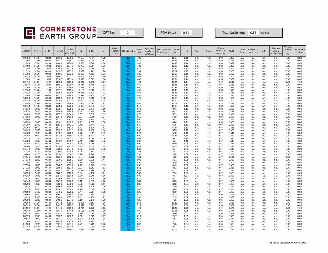
2 0.50 Total Settlement: 0.53 (Inches)
Depth (ft) qc (tsf) fs (tsf) σvc (psf)Insitu
σ'vc (psf)Q F (%) Ic
Layer "Plastic"PI > 7
Flag Soil TypeFines (%)
qcN near interfaces (soft layer)
Thin Layer Factor (KH)
Interpreted
qcNCN qc1N qc1N-CS
Stress Reduction
Coeff, rd
CSRKσ for Sand
CRRM=7.5,
σ'vc = 1 atmCRR
Factor of Safety
(CRR/CSR)
Vertical Strain
εv
Settlement (Inches)
CPT No. PGA (Amax)
10.990 17.300 0.800 1361.3 1205.9 27.563 4.814 2.78 Clay 40.0 16.35 1.16 n.a. n.a. 0.99 0.392 n.a. n.a. n.a. n.a. 0.00 0.0011.160 17.300 0.900 1381.7 1215.7 27.324 5.419 2.82 Clay 41.5 16.35 1.16 n.a. n.a. 0.99 0.395 n.a. n.a. n.a. n.a. 0.00 0.0011.320 17.900 0.900 1400.9 1224.9 28.082 5.233 2.80 Clay 40.8 16.92 1.16 n.a. n.a. 0.98 0.397 n.a. n.a. n.a. n.a. 0.00 0.0011.480 17.200 1.000 1420.1 1234.1 26.723 6.064 2.86 Clay 43.1 16.26 1.15 n.a. n.a. 0.98 0.399 n.a. n.a. n.a. n.a. 0.00 0.0011.650 18.300 1.000 1440.5 1243.9 28.265 5.688 2.82 Clay 41.6 17.30 1.15 n.a. n.a. 0.98 0.401 n.a. n.a. n.a. n.a. 0.00 0.0011.810 18.800 0.900 1459.7 1253.2 28.839 4.981 2.78 Clay 39.9 17.77 1.15 n.a. n.a. 0.98 0.403 n.a. n.a. n.a. n.a. 0.00 0.0011.980 20.300 0.900 1480.1 1262.9 30.975 4.601 2.73 Clay 38.2 19.19 1.15 n.a. n.a. 0.98 0.405 n.a. n.a. n.a. n.a. 0.00 0.0012.140 19.200 1.000 1499.3 1272.2 29.006 5.420 2.80 Clay 40.8 18.15 1.14 n.a. n.a. 0.98 0.407 n.a. n.a. n.a. n.a. 0.00 0.0012.300 19.400 1.000 1518.5 1281.4 29.095 5.365 2.80 Clay 40.6 18.34 1.14 n.a. n.a. 0.98 0.409 n.a. n.a. n.a. n.a. 0.00 0.0012.470 17.800 1.000 1538.9 1291.2 26.380 5.872 2.86 Clay 42.8 16.82 1.14 n.a. n.a. 0.98 0.411 n.a. n.a. n.a. n.a. 0.00 0.0012.630 16.200 1.000 1558.1 1300.4 23.717 6.485 2.92 Clay 45.3 15.31 1.14 n.a. n.a. 0.98 0.413 n.a. n.a. n.a. n.a. 0.00 0.0012.800 16.300 1.100 1578.5 1310.2 23.677 7.092 2.95 Clay 46.5 15.41 1.13 n.a. n.a. 0.98 0.414 n.a. n.a. n.a. n.a. 0.00 0.0012.960 17.400 1.100 1597.7 1319.4 25.165 6.626 2.91 Clay 44.9 16.45 1.13 n.a. n.a. 0.98 0.416 n.a. n.a. n.a. n.a. 0.00 0.0013.120 17.200 1.100 1616.9 1328.6 24.675 6.711 2.92 Clay 45.3 16.26 1.13 n.a. n.a. 0.98 0.418 n.a. n.a. n.a. n.a. 0.00 0.0013.290 15.500 0.900 1637.3 1338.4 21.939 6.130 2.93 Clay 45.7 14.65 1.13 n.a. n.a. 0.98 0.420 n.a. n.a. n.a. n.a. 0.00 0.0013.450 14.700 0.900 1656.5 1347.6 20.587 6.488 2.96 Clay 47.2 13.89 1.13 n.a. n.a. 0.98 0.421 n.a. n.a. n.a. n.a. 0.00 0.0013.620 16.000 0.900 1676.9 1357.4 22.339 5.936 2.91 Clay 45.0 15.12 1.12 n.a. n.a. 0.98 0.423 n.a. n.a. n.a. n.a. 0.00 0.0013.780 14.900 0.800 1696.1 1366.6 20.564 5.693 2.92 Clay 45.6 14.08 1.12 n.a. n.a. 0.98 0.425 n.a. n.a. n.a. n.a. 0.00 0.0013.940 11.900 0.800 1715.3 1375.8 16.052 7.245 3.07 Clay 51.9 11.25 1.12 n.a. n.a. 0.98 0.426 n.a. n.a. n.a. n.a. 0.00 0.0014.110 8.900 0.600 1735.7 1385.6 11.593 7.470 3.19 Clay 57.1 8.41 1.12 n.a. n.a. 0.98 0.428 n.a. n.a. n.a. n.a. 0.00 0.0014.270 6.800 0.400 1754.9 1394.9 8.492 6.754 3.26 Clay 60.7 6.43 1.12 n.a. n.a. 0.98 0.429 n.a. n.a. n.a. n.a. 0.00 0.0014.440 5.700 0.400 1775.3 1404.6 6.852 8.312 3.39 Clay 67.1 5.39 1.11 n.a. n.a. 0.98 0.431 n.a. n.a. n.a. n.a. 0.00 0.0014.600 5.900 0.400 1794.5 1413.9 7.077 7.996 3.37 Clay 66.0 5.58 1.11 n.a. n.a. 0.98 0.432 n.a. n.a. n.a. n.a. 0.00 0.0014.760 6.100 0.400 1813.7 1423.1 7.298 7.702 3.35 Clay 65.0 5.77 1.11 n.a. n.a. 0.98 0.434 n.a. n.a. n.a. n.a. 0.00 0.0014.930 6.600 0.400 1834.1 1432.9 7.932 7.039 3.30 Clay 62.4 6.24 1.11 n.a. n.a. 0.98 0.435 n.a. n.a. n.a. n.a. 0.00 0.0015.090 6.300 0.400 1853.3 1442.1 7.452 7.444 3.34 Clay 64.2 5.95 1.11 n.a. n.a. 0.98 0.437 n.a. n.a. n.a. n.a. 0.00 0.0015.260 5.600 0.400 1873.7 1451.9 6.424 8.578 3.42 Clay 68.7 5.29 1.10 n.a. n.a. 0.98 0.438 n.a. n.a. n.a. n.a. 0.00 0.0015.420 6.300 0.400 1892.9 1461.1 7.328 7.472 3.34 Clay 64.5 5.95 1.10 n.a. n.a. 0.97 0.439 n.a. n.a. n.a. n.a. 0.00 0.0015.580 5.900 0.400 1912.1 1470.3 6.725 8.091 3.39 Clay 67.1 5.58 1.10 n.a. n.a. 0.97 0.441 n.a. n.a. n.a. n.a. 0.00 0.0015.750 5.600 0.400 1932.5 1480.1 6.261 8.632 3.43 Clay 69.2 5.29 1.10 n.a. n.a. 0.97 0.442 n.a. n.a. n.a. n.a. 0.00 0.0015.910 6.100 0.400 1951.7 1489.3 6.881 7.806 3.38 Clay 66.2 5.77 1.10 n.a. n.a. 0.97 0.443 n.a. n.a. n.a. n.a. 0.00 0.0016 080 6 600 0 400 1972 1 1499 1 7 490 7 125 3 32 Clay 63 5 6 24 1 10 n a n a 0 97 0 445 n a n a n a n a 0 00 0 0016.080 6.600 0.400 1972.1 1499.1 7.490 7.125 3.32 Clay 63.5 6.24 1.10 n.a. n.a. 0.97 0.445 n.a. n.a. n.a. n.a. 0.00 0.0016.240 7.400 0.400 1991.3 1508.3 8.492 6.246 3.24 Clay 59.7 6.99 1.09 n.a. n.a. 0.97 0.446 n.a. n.a. n.a. n.a. 0.00 0.0016.400 6.400 0.400 2010.5 1517.5 7.110 7.415 3.35 Clay 64.9 6.05 1.09 n.a. n.a. 0.97 0.447 n.a. n.a. n.a. n.a. 0.00 0.0016.570 6.000 0.300 2030.9 1527.3 6.527 6.019 3.32 Clay 63.6 5.67 1.09 n.a. n.a. 0.97 0.448 n.a. n.a. n.a. n.a. 0.00 0.0016.730 4.700 0.300 2050.1 1536.5 4.783 8.163 3.51 Clay 73.4 4.44 1.09 n.a. n.a. 0.97 0.449 n.a. n.a. n.a. n.a. 0.00 0.0016.900 4.100 0.300 2070.5 1546.3 3.964 9.789 3.62 Clay 79.6 3.88 1.09 n.a. n.a. 0.97 0.451 n.a. n.a. n.a. n.a. 0.00 0.0017.060 4.500 0.300 2089.7 1555.6 4.442 8.683 3.55 Clay 75.6 4.25 1.08 n.a. n.a. 0.97 0.452 n.a. n.a. n.a. n.a. 0.00 0.0017.230 5.200 0.300 2110.1 1565.3 5.296 7.238 3.44 Clay 69.8 4.91 1.08 n.a. n.a. 0.97 0.453 n.a. n.a. n.a. n.a. 0.00 0.0017.390 5.900 0.300 2129.3 1574.6 6.142 6.204 3.35 Clay 65.1 5.58 1.08 n.a. n.a. 0.97 0.454 n.a. n.a. n.a. n.a. 0.00 0.0017.550 6.800 0.400 2148.5 1583.8 7.230 6.986 3.33 Clay 63.8 6.43 1.08 n.a. n.a. 0.97 0.455 n.a. n.a. n.a. n.a. 0.00 0.0017.720 9.000 0.400 2168.9 1593.6 9.934 5.053 3.13 Clay 54.5 8.51 1.08 n.a. n.a. 0.97 0.456 n.a. n.a. n.a. n.a. 0.00 0.0017.880 10.600 0.300 2188.1 1602.8 11.862 3.156 2.95 Clay 46.6 10.02 1.08 n.a. n.a. 0.97 0.457 n.a. n.a. n.a. n.a. 0.00 0.0018.050 8.400 0.300 2208.5 1612.6 9.049 4.112 3.11 Clay 53.6 7.94 1.07 n.a. n.a. 0.97 0.458 n.a. n.a. n.a. n.a. 0.00 0.0018.210 8.300 0.400 2227.7 1621.8 8.862 5.566 3.20 Clay 57.5 7.84 1.07 n.a. n.a. 0.97 0.459 n.a. n.a. n.a. n.a. 0.00 0.0018.370 9.600 0.400 2246.9 1631.0 10.394 4.719 3.10 Clay 53.0 9.07 1.07 n.a. n.a. 0.97 0.460 n.a. n.a. n.a. n.a. 0.00 0.0018.540 8.600 0.300 2267.3 1640.8 9.101 4.018 3.10 Clay 53.2 8.13 1.07 n.a. n.a. 0.97 0.461 n.a. n.a. n.a. n.a. 0.00 0.0018.700 8.600 0.300 2286.5 1650.0 9.038 4.023 3.11 Clay 53.3 8.13 1.07 n.a. n.a. 0.97 0.462 n.a. n.a. n.a. n.a. 0.00 0.0018.870 9.200 0.300 2306.9 1659.8 9.696 3.728 3.06 Clay 51.4 8.70 1.07 n.a. n.a. 0.97 0.463 n.a. n.a. n.a. n.a. 0.00 0.0019.030 9.500 0.300 2326.1 1669.0 9.990 3.598 3.04 Clay 50.5 8.98 1.06 n.a. n.a. 0.97 0.464 n.a. n.a. n.a. n.a. 0.00 0.0019.190 9.100 0.300 2345.3 1678.2 9.447 3.784 3.08 Clay 52.0 8.60 1.06 n.a. n.a. 0.97 0.465 n.a. n.a. n.a. n.a. 0.00 0.0019.360 8.500 0.300 2365.7 1688.0 8.669 4.100 3.13 Clay 54.2 8.03 1.06 n.a. n.a. 0.96 0.466 n.a. n.a. n.a. n.a. 0.00 0.0019.520 7.500 0.300 2384.9 1697.3 7.433 4.756 3.22 Clay 58.4 7.09 1.06 n.a. n.a. 0.96 0.467 n.a. n.a. n.a. n.a. 0.00 0.0019.690 8.200 0.500 2405.3 1707.0 8.198 7.146 3.29 Clay 62.0 7.75 1.06 n.a. n.a. 0.96 0.468 n.a. n.a. n.a. n.a. 0.00 0.0019.850 11.000 0.700 2424.5 1716.3 11.406 7.152 3.18 Clay 56.8 10.40 1.06 n.a. n.a. 0.96 0.469 n.a. n.a. n.a. n.a. 0.00 0.0020.010 14.000 0.800 2443.7 1725.5 14.811 6.261 3.06 Clay 51.2 13.23 1.06 n.a. n.a. 0.96 0.469 n.a. n.a. n.a. n.a. 0.00 0.0020.180 13.200 0.600 2464.1 1735.3 13.794 5.013 3.02 Clay 49.5 12.48 1.05 n.a. n.a. 0.96 0.470 n.a. n.a. n.a. n.a. 0.00 0.0020.340 11.800 0.400 2483.3 1744.5 12.105 3.788 2.99 Clay 48.2 11.15 1.05 n.a. n.a. 0.96 0.471 n.a. n.a. n.a. n.a. 0.00 0.0020.510 9.800 0.500 2503.7 1754.3 9.746 5.849 3.18 Clay 56.6 9.26 1.05 n.a. n.a. 0.96 0.472 n.a. n.a. n.a. n.a. 0.00 0.0020.670 7.900 0.400 2522.9 1763.5 7.529 6.025 3.27 Clay 61.2 7.47 1.05 n.a. n.a. 0.96 0.473 n.a. n.a. n.a. n.a. 0.00 0.0020.830 9.000 0.400 2542.1 1772.7 8.720 5.175 3.18 Clay 56.9 8.51 1.05 n.a. n.a. 0.96 0.473 n.a. n.a. n.a. n.a. 0.00 0.0021.000 8.700 0.400 2562.5 1782.5 8.324 5.392 3.21 Clay 58.1 8.22 1.05 n.a. n.a. 0.96 0.474 n.a. n.a. n.a. n.a. 0.00 0.0021.160 8.200 0.400 2581.7 1791.7 7.712 5.789 3.26 Clay 60.3 7.75 1.04 n.a. n.a. 0.96 0.475 n.a. n.a. n.a. n.a. 0.00 0.0021.330 10.200 0.500 2602.1 1801.5 9.879 5.619 3.16 Clay 55.9 9.64 1.04 n.a. n.a. 0.96 0.476 n.a. n.a. n.a. n.a. 0.00 0.0021.490 11.700 0.300 2621.3 1810.7 11.475 2.888 2.94 Clay 46.2 11.06 1.04 n.a. n.a. 0.96 0.476 n.a. n.a. n.a. n.a. 0.00 0.00
Page 2 Calculations (8/1/2014) P4285 Design Liquefaction Analysis CPT-2
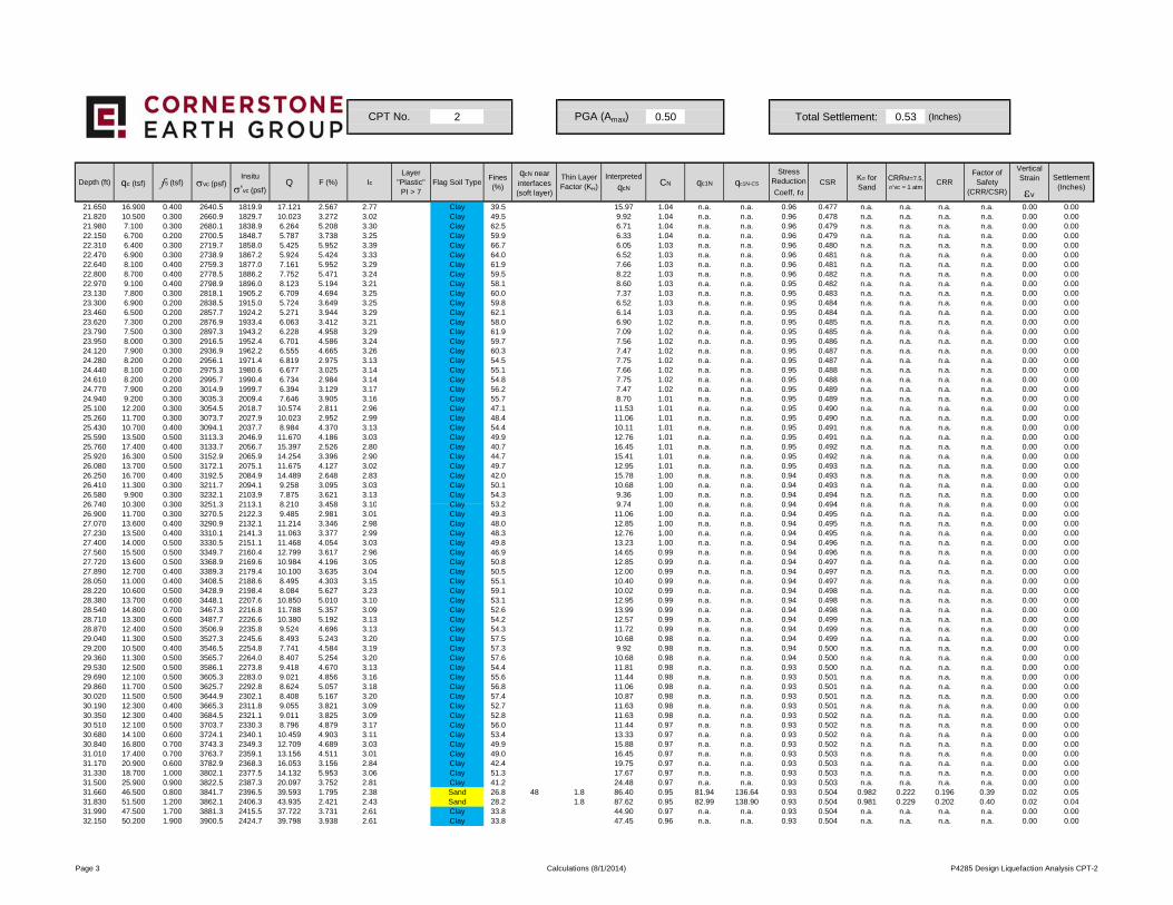
2 0.50 Total Settlement: 0.53 (Inches)
Depth (ft) qc (tsf) fs (tsf) σvc (psf)Insitu
σ'vc (psf)Q F (%) Ic
Layer "Plastic"PI > 7
Flag Soil TypeFines (%)
qcN near interfaces (soft layer)
Thin Layer Factor (KH)
Interpreted
qcNCN qc1N qc1N-CS
Stress Reduction
Coeff, rd
CSRKσ for Sand
CRRM=7.5,
σ'vc = 1 atmCRR
Factor of Safety
(CRR/CSR)
Vertical Strain
εv
Settlement (Inches)
CPT No. PGA (Amax)
21.650 16.900 0.400 2640.5 1819.9 17.121 2.567 2.77 Clay 39.5 15.97 1.04 n.a. n.a. 0.96 0.477 n.a. n.a. n.a. n.a. 0.00 0.0021.820 10.500 0.300 2660.9 1829.7 10.023 3.272 3.02 Clay 49.5 9.92 1.04 n.a. n.a. 0.96 0.478 n.a. n.a. n.a. n.a. 0.00 0.0021.980 7.100 0.300 2680.1 1838.9 6.264 5.208 3.30 Clay 62.5 6.71 1.04 n.a. n.a. 0.96 0.479 n.a. n.a. n.a. n.a. 0.00 0.0022.150 6.700 0.200 2700.5 1848.7 5.787 3.738 3.25 Clay 59.9 6.33 1.04 n.a. n.a. 0.96 0.479 n.a. n.a. n.a. n.a. 0.00 0.0022.310 6.400 0.300 2719.7 1858.0 5.425 5.952 3.39 Clay 66.7 6.05 1.03 n.a. n.a. 0.96 0.480 n.a. n.a. n.a. n.a. 0.00 0.0022.470 6.900 0.300 2738.9 1867.2 5.924 5.424 3.33 Clay 64.0 6.52 1.03 n.a. n.a. 0.96 0.481 n.a. n.a. n.a. n.a. 0.00 0.0022.640 8.100 0.400 2759.3 1877.0 7.161 5.952 3.29 Clay 61.9 7.66 1.03 n.a. n.a. 0.96 0.481 n.a. n.a. n.a. n.a. 0.00 0.0022.800 8.700 0.400 2778.5 1886.2 7.752 5.471 3.24 Clay 59.5 8.22 1.03 n.a. n.a. 0.96 0.482 n.a. n.a. n.a. n.a. 0.00 0.0022.970 9.100 0.400 2798.9 1896.0 8.123 5.194 3.21 Clay 58.1 8.60 1.03 n.a. n.a. 0.95 0.482 n.a. n.a. n.a. n.a. 0.00 0.0023.130 7.800 0.300 2818.1 1905.2 6.709 4.694 3.25 Clay 60.0 7.37 1.03 n.a. n.a. 0.95 0.483 n.a. n.a. n.a. n.a. 0.00 0.0023.300 6.900 0.200 2838.5 1915.0 5.724 3.649 3.25 Clay 59.8 6.52 1.03 n.a. n.a. 0.95 0.484 n.a. n.a. n.a. n.a. 0.00 0.0023.460 6.500 0.200 2857.7 1924.2 5.271 3.944 3.29 Clay 62.1 6.14 1.03 n.a. n.a. 0.95 0.484 n.a. n.a. n.a. n.a. 0.00 0.0023.620 7.300 0.200 2876.9 1933.4 6.063 3.412 3.21 Clay 58.0 6.90 1.02 n.a. n.a. 0.95 0.485 n.a. n.a. n.a. n.a. 0.00 0.0023.790 7.500 0.300 2897.3 1943.2 6.228 4.958 3.29 Clay 61.9 7.09 1.02 n.a. n.a. 0.95 0.485 n.a. n.a. n.a. n.a. 0.00 0.0023.950 8.000 0.300 2916.5 1952.4 6.701 4.586 3.24 Clay 59.7 7.56 1.02 n.a. n.a. 0.95 0.486 n.a. n.a. n.a. n.a. 0.00 0.0024.120 7.900 0.300 2936.9 1962.2 6.555 4.665 3.26 Clay 60.3 7.47 1.02 n.a. n.a. 0.95 0.487 n.a. n.a. n.a. n.a. 0.00 0.0024.280 8.200 0.200 2956.1 1971.4 6.819 2.975 3.13 Clay 54.5 7.75 1.02 n.a. n.a. 0.95 0.487 n.a. n.a. n.a. n.a. 0.00 0.0024.440 8.100 0.200 2975.3 1980.6 6.677 3.025 3.14 Clay 55.1 7.66 1.02 n.a. n.a. 0.95 0.488 n.a. n.a. n.a. n.a. 0.00 0.0024.610 8.200 0.200 2995.7 1990.4 6.734 2.984 3.14 Clay 54.8 7.75 1.02 n.a. n.a. 0.95 0.488 n.a. n.a. n.a. n.a. 0.00 0.0024.770 7.900 0.200 3014.9 1999.7 6.394 3.129 3.17 Clay 56.2 7.47 1.02 n.a. n.a. 0.95 0.489 n.a. n.a. n.a. n.a. 0.00 0.0024.940 9.200 0.300 3035.3 2009.4 7.646 3.905 3.16 Clay 55.7 8.70 1.01 n.a. n.a. 0.95 0.489 n.a. n.a. n.a. n.a. 0.00 0.0025.100 12.200 0.300 3054.5 2018.7 10.574 2.811 2.96 Clay 47.1 11.53 1.01 n.a. n.a. 0.95 0.490 n.a. n.a. n.a. n.a. 0.00 0.0025.260 11.700 0.300 3073.7 2027.9 10.023 2.952 2.99 Clay 48.4 11.06 1.01 n.a. n.a. 0.95 0.490 n.a. n.a. n.a. n.a. 0.00 0.0025.430 10.700 0.400 3094.1 2037.7 8.984 4.370 3.13 Clay 54.4 10.11 1.01 n.a. n.a. 0.95 0.491 n.a. n.a. n.a. n.a. 0.00 0.0025.590 13.500 0.500 3113.3 2046.9 11.670 4.186 3.03 Clay 49.9 12.76 1.01 n.a. n.a. 0.95 0.491 n.a. n.a. n.a. n.a. 0.00 0.0025.760 17.400 0.400 3133.7 2056.7 15.397 2.526 2.80 Clay 40.7 16.45 1.01 n.a. n.a. 0.95 0.492 n.a. n.a. n.a. n.a. 0.00 0.0025.920 16.300 0.500 3152.9 2065.9 14.254 3.396 2.90 Clay 44.7 15.41 1.01 n.a. n.a. 0.95 0.492 n.a. n.a. n.a. n.a. 0.00 0.0026.080 13.700 0.500 3172.1 2075.1 11.675 4.127 3.02 Clay 49.7 12.95 1.01 n.a. n.a. 0.95 0.493 n.a. n.a. n.a. n.a. 0.00 0.0026.250 16.700 0.400 3192.5 2084.9 14.489 2.648 2.83 Clay 42.0 15.78 1.00 n.a. n.a. 0.94 0.493 n.a. n.a. n.a. n.a. 0.00 0.0026.410 11.300 0.300 3211.7 2094.1 9.258 3.095 3.03 Clay 50.1 10.68 1.00 n.a. n.a. 0.94 0.493 n.a. n.a. n.a. n.a. 0.00 0.0026.580 9.900 0.300 3232.1 2103.9 7.875 3.621 3.13 Clay 54.3 9.36 1.00 n.a. n.a. 0.94 0.494 n.a. n.a. n.a. n.a. 0.00 0.0026 740 10 300 0 300 3251 3 2113 1 8 210 3 458 3 10 Clay 53 2 9 74 1 00 n a n a 0 94 0 494 n a n a n a n a 0 00 0 0026.740 10.300 0.300 3251.3 2113.1 8.210 3.458 3.10 Clay 53.2 9.74 1.00 n.a. n.a. 0.94 0.494 n.a. n.a. n.a. n.a. 0.00 0.0026.900 11.700 0.300 3270.5 2122.3 9.485 2.981 3.01 Clay 49.3 11.06 1.00 n.a. n.a. 0.94 0.495 n.a. n.a. n.a. n.a. 0.00 0.0027.070 13.600 0.400 3290.9 2132.1 11.214 3.346 2.98 Clay 48.0 12.85 1.00 n.a. n.a. 0.94 0.495 n.a. n.a. n.a. n.a. 0.00 0.0027.230 13.500 0.400 3310.1 2141.3 11.063 3.377 2.99 Clay 48.3 12.76 1.00 n.a. n.a. 0.94 0.495 n.a. n.a. n.a. n.a. 0.00 0.0027.400 14.000 0.500 3330.5 2151.1 11.468 4.054 3.03 Clay 49.8 13.23 1.00 n.a. n.a. 0.94 0.496 n.a. n.a. n.a. n.a. 0.00 0.0027.560 15.500 0.500 3349.7 2160.4 12.799 3.617 2.96 Clay 46.9 14.65 0.99 n.a. n.a. 0.94 0.496 n.a. n.a. n.a. n.a. 0.00 0.0027.720 13.600 0.500 3368.9 2169.6 10.984 4.196 3.05 Clay 50.8 12.85 0.99 n.a. n.a. 0.94 0.497 n.a. n.a. n.a. n.a. 0.00 0.0027.890 12.700 0.400 3389.3 2179.4 10.100 3.635 3.04 Clay 50.5 12.00 0.99 n.a. n.a. 0.94 0.497 n.a. n.a. n.a. n.a. 0.00 0.0028.050 11.000 0.400 3408.5 2188.6 8.495 4.303 3.15 Clay 55.1 10.40 0.99 n.a. n.a. 0.94 0.497 n.a. n.a. n.a. n.a. 0.00 0.0028.220 10.600 0.500 3428.9 2198.4 8.084 5.627 3.23 Clay 59.1 10.02 0.99 n.a. n.a. 0.94 0.498 n.a. n.a. n.a. n.a. 0.00 0.0028.380 13.700 0.600 3448.1 2207.6 10.850 5.010 3.10 Clay 53.1 12.95 0.99 n.a. n.a. 0.94 0.498 n.a. n.a. n.a. n.a. 0.00 0.0028.540 14.800 0.700 3467.3 2216.8 11.788 5.357 3.09 Clay 52.6 13.99 0.99 n.a. n.a. 0.94 0.498 n.a. n.a. n.a. n.a. 0.00 0.0028.710 13.300 0.600 3487.7 2226.6 10.380 5.192 3.13 Clay 54.2 12.57 0.99 n.a. n.a. 0.94 0.499 n.a. n.a. n.a. n.a. 0.00 0.0028.870 12.400 0.500 3506.9 2235.8 9.524 4.696 3.13 Clay 54.3 11.72 0.99 n.a. n.a. 0.94 0.499 n.a. n.a. n.a. n.a. 0.00 0.0029.040 11.300 0.500 3527.3 2245.6 8.493 5.243 3.20 Clay 57.5 10.68 0.98 n.a. n.a. 0.94 0.499 n.a. n.a. n.a. n.a. 0.00 0.0029.200 10.500 0.400 3546.5 2254.8 7.741 4.584 3.19 Clay 57.3 9.92 0.98 n.a. n.a. 0.94 0.500 n.a. n.a. n.a. n.a. 0.00 0.0029.360 11.300 0.500 3565.7 2264.0 8.407 5.254 3.20 Clay 57.6 10.68 0.98 n.a. n.a. 0.94 0.500 n.a. n.a. n.a. n.a. 0.00 0.0029.530 12.500 0.500 3586.1 2273.8 9.418 4.670 3.13 Clay 54.4 11.81 0.98 n.a. n.a. 0.93 0.500 n.a. n.a. n.a. n.a. 0.00 0.0029.690 12.100 0.500 3605.3 2283.0 9.021 4.856 3.16 Clay 55.6 11.44 0.98 n.a. n.a. 0.93 0.501 n.a. n.a. n.a. n.a. 0.00 0.0029.860 11.700 0.500 3625.7 2292.8 8.624 5.057 3.18 Clay 56.8 11.06 0.98 n.a. n.a. 0.93 0.501 n.a. n.a. n.a. n.a. 0.00 0.0030.020 11.500 0.500 3644.9 2302.1 8.408 5.167 3.20 Clay 57.4 10.87 0.98 n.a. n.a. 0.93 0.501 n.a. n.a. n.a. n.a. 0.00 0.0030.190 12.300 0.400 3665.3 2311.8 9.055 3.821 3.09 Clay 52.7 11.63 0.98 n.a. n.a. 0.93 0.501 n.a. n.a. n.a. n.a. 0.00 0.0030.350 12.300 0.400 3684.5 2321.1 9.011 3.825 3.09 Clay 52.8 11.63 0.98 n.a. n.a. 0.93 0.502 n.a. n.a. n.a. n.a. 0.00 0.0030.510 12.100 0.500 3703.7 2330.3 8.796 4.879 3.17 Clay 56.0 11.44 0.97 n.a. n.a. 0.93 0.502 n.a. n.a. n.a. n.a. 0.00 0.0030.680 14.100 0.600 3724.1 2340.1 10.459 4.903 3.11 Clay 53.4 13.33 0.97 n.a. n.a. 0.93 0.502 n.a. n.a. n.a. n.a. 0.00 0.0030.840 16.800 0.700 3743.3 2349.3 12.709 4.689 3.03 Clay 49.9 15.88 0.97 n.a. n.a. 0.93 0.502 n.a. n.a. n.a. n.a. 0.00 0.0031.010 17.400 0.700 3763.7 2359.1 13.156 4.511 3.01 Clay 49.0 16.45 0.97 n.a. n.a. 0.93 0.503 n.a. n.a. n.a. n.a. 0.00 0.0031.170 20.900 0.600 3782.9 2368.3 16.053 3.156 2.84 Clay 42.4 19.75 0.97 n.a. n.a. 0.93 0.503 n.a. n.a. n.a. n.a. 0.00 0.0031.330 18.700 1.000 3802.1 2377.5 14.132 5.953 3.06 Clay 51.3 17.67 0.97 n.a. n.a. 0.93 0.503 n.a. n.a. n.a. n.a. 0.00 0.0031.500 25.900 0.900 3822.5 2387.3 20.097 3.752 2.81 Clay 41.2 24.48 0.97 n.a. n.a. 0.93 0.503 n.a. n.a. n.a. n.a. 0.00 0.0031.660 46.500 0.800 3841.7 2396.5 39.593 1.795 2.38 Sand 26.8 48 1.8 86.40 0.95 81.94 136.64 0.93 0.504 0.982 0.222 0.196 0.39 0.02 0.0531.830 51.500 1.200 3862.1 2406.3 43.935 2.421 2.43 Sand 28.2 1.8 87.62 0.95 82.99 138.90 0.93 0.504 0.981 0.229 0.202 0.40 0.02 0.0431.990 47.500 1.700 3881.3 2415.5 37.722 3.731 2.61 Clay 33.8 44.90 0.97 n.a. n.a. 0.93 0.504 n.a. n.a. n.a. n.a. 0.00 0.0032.150 50.200 1.900 3900.5 2424.7 39.798 3.938 2.61 Clay 33.8 47.45 0.96 n.a. n.a. 0.93 0.504 n.a. n.a. n.a. n.a. 0.00 0.00
Page 3 Calculations (8/1/2014) P4285 Design Liquefaction Analysis CPT-2
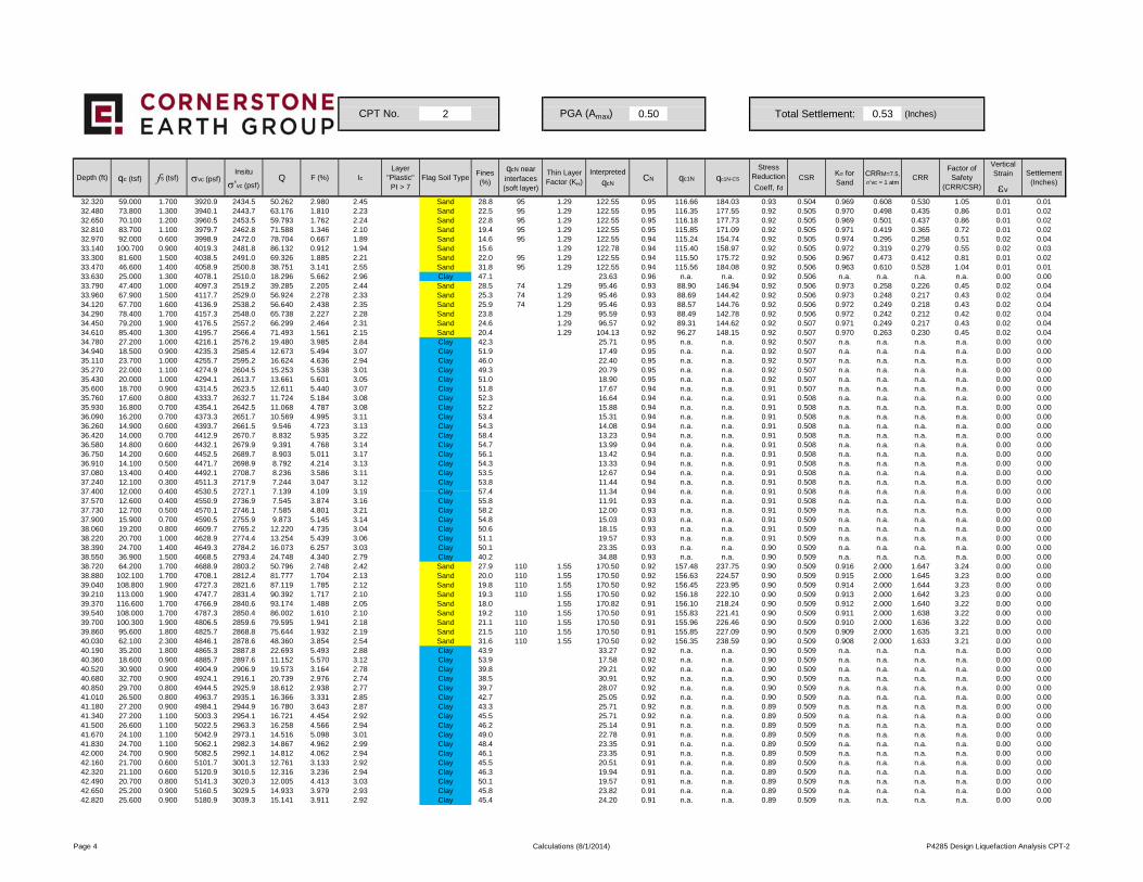
2 0.50 Total Settlement: 0.53 (Inches)
Depth (ft) qc (tsf) fs (tsf) σvc (psf)Insitu
σ'vc (psf)Q F (%) Ic
Layer "Plastic"PI > 7
Flag Soil TypeFines (%)
qcN near interfaces (soft layer)
Thin Layer Factor (KH)
Interpreted
qcNCN qc1N qc1N-CS
Stress Reduction
Coeff, rd
CSRKσ for Sand
CRRM=7.5,
σ'vc = 1 atmCRR
Factor of Safety
(CRR/CSR)
Vertical Strain
εv
Settlement (Inches)
CPT No. PGA (Amax)
32.320 59.000 1.700 3920.9 2434.5 50.262 2.980 2.45 Sand 28.8 95 1.29 122.55 0.95 116.66 184.03 0.93 0.504 0.969 0.608 0.530 1.05 0.01 0.0132.480 73.800 1.300 3940.1 2443.7 63.176 1.810 2.23 Sand 22.5 95 1.29 122.55 0.95 116.35 177.55 0.92 0.505 0.970 0.498 0.435 0.86 0.01 0.0232.650 70.100 1.200 3960.5 2453.5 59.793 1.762 2.24 Sand 22.8 95 1.29 122.55 0.95 116.18 177.73 0.92 0.505 0.969 0.501 0.437 0.86 0.01 0.0232.810 83.700 1.100 3979.7 2462.8 71.588 1.346 2.10 Sand 19.4 95 1.29 122.55 0.95 115.85 171.09 0.92 0.505 0.971 0.419 0.365 0.72 0.01 0.0232.970 92.000 0.600 3998.9 2472.0 78.704 0.667 1.89 Sand 14.6 95 1.29 122.55 0.94 115.24 154.74 0.92 0.505 0.974 0.295 0.258 0.51 0.02 0.0433.140 100.700 0.900 4019.3 2481.8 86.132 0.912 1.94 Sand 15.6 1.29 122.78 0.94 115.40 158.97 0.92 0.505 0.972 0.319 0.279 0.55 0.02 0.0333.300 81.600 1.500 4038.5 2491.0 69.326 1.885 2.21 Sand 22.0 95 1.29 122.55 0.94 115.50 175.72 0.92 0.506 0.967 0.473 0.412 0.81 0.01 0.0233.470 46.600 1.400 4058.9 2500.8 38.751 3.141 2.55 Sand 31.8 95 1.29 122.55 0.94 115.56 184.08 0.92 0.506 0.963 0.610 0.528 1.04 0.01 0.0133.630 25.000 1.300 4078.1 2510.0 18.296 5.662 2.96 Clay 47.1 23.63 0.96 n.a. n.a. 0.92 0.506 n.a. n.a. n.a. n.a. 0.00 0.0033.790 47.400 1.000 4097.3 2519.2 39.285 2.205 2.44 Sand 28.5 74 1.29 95.46 0.93 88.90 146.94 0.92 0.506 0.973 0.258 0.226 0.45 0.02 0.0433.960 67.900 1.500 4117.7 2529.0 56.924 2.278 2.33 Sand 25.3 74 1.29 95.46 0.93 88.69 144.42 0.92 0.506 0.973 0.248 0.217 0.43 0.02 0.0434.120 67.700 1.600 4136.9 2538.2 56.640 2.438 2.35 Sand 25.9 74 1.29 95.46 0.93 88.57 144.76 0.92 0.506 0.972 0.249 0.218 0.43 0.02 0.0434.290 78.400 1.700 4157.3 2548.0 65.738 2.227 2.28 Sand 23.8 1.29 95.59 0.93 88.49 142.78 0.92 0.506 0.972 0.242 0.212 0.42 0.02 0.0434.450 79.200 1.900 4176.5 2557.2 66.299 2.464 2.31 Sand 24.6 1.29 96.57 0.92 89.31 144.62 0.92 0.507 0.971 0.249 0.217 0.43 0.02 0.0434.610 85.400 1.300 4195.7 2566.4 71.493 1.561 2.15 Sand 20.4 1.29 104.13 0.92 96.27 148.15 0.92 0.507 0.970 0.263 0.230 0.45 0.02 0.0434.780 27.200 1.000 4216.1 2576.2 19.480 3.985 2.84 Clay 42.3 25.71 0.95 n.a. n.a. 0.92 0.507 n.a. n.a. n.a. n.a. 0.00 0.0034.940 18.500 0.900 4235.3 2585.4 12.673 5.494 3.07 Clay 51.9 17.49 0.95 n.a. n.a. 0.92 0.507 n.a. n.a. n.a. n.a. 0.00 0.0035.110 23.700 1.000 4255.7 2595.2 16.624 4.636 2.94 Clay 46.0 22.40 0.95 n.a. n.a. 0.92 0.507 n.a. n.a. n.a. n.a. 0.00 0.0035.270 22.000 1.100 4274.9 2604.5 15.253 5.538 3.01 Clay 49.3 20.79 0.95 n.a. n.a. 0.92 0.507 n.a. n.a. n.a. n.a. 0.00 0.0035.430 20.000 1.000 4294.1 2613.7 13.661 5.601 3.05 Clay 51.0 18.90 0.95 n.a. n.a. 0.92 0.507 n.a. n.a. n.a. n.a. 0.00 0.0035.600 18.700 0.900 4314.5 2623.5 12.611 5.440 3.07 Clay 51.8 17.67 0.94 n.a. n.a. 0.91 0.507 n.a. n.a. n.a. n.a. 0.00 0.0035.760 17.600 0.800 4333.7 2632.7 11.724 5.184 3.08 Clay 52.3 16.64 0.94 n.a. n.a. 0.91 0.508 n.a. n.a. n.a. n.a. 0.00 0.0035.930 16.800 0.700 4354.1 2642.5 11.068 4.787 3.08 Clay 52.2 15.88 0.94 n.a. n.a. 0.91 0.508 n.a. n.a. n.a. n.a. 0.00 0.0036.090 16.200 0.700 4373.3 2651.7 10.569 4.995 3.11 Clay 53.4 15.31 0.94 n.a. n.a. 0.91 0.508 n.a. n.a. n.a. n.a. 0.00 0.0036.260 14.900 0.600 4393.7 2661.5 9.546 4.723 3.13 Clay 54.3 14.08 0.94 n.a. n.a. 0.91 0.508 n.a. n.a. n.a. n.a. 0.00 0.0036.420 14.000 0.700 4412.9 2670.7 8.832 5.935 3.22 Clay 58.4 13.23 0.94 n.a. n.a. 0.91 0.508 n.a. n.a. n.a. n.a. 0.00 0.0036.580 14.800 0.600 4432.1 2679.9 9.391 4.768 3.14 Clay 54.7 13.99 0.94 n.a. n.a. 0.91 0.508 n.a. n.a. n.a. n.a. 0.00 0.0036.750 14.200 0.600 4452.5 2689.7 8.903 5.011 3.17 Clay 56.1 13.42 0.94 n.a. n.a. 0.91 0.508 n.a. n.a. n.a. n.a. 0.00 0.0036.910 14.100 0.500 4471.7 2698.9 8.792 4.214 3.13 Clay 54.3 13.33 0.94 n.a. n.a. 0.91 0.508 n.a. n.a. n.a. n.a. 0.00 0.0037.080 13.400 0.400 4492.1 2708.7 8.236 3.586 3.11 Clay 53.5 12.67 0.94 n.a. n.a. 0.91 0.508 n.a. n.a. n.a. n.a. 0.00 0.0037.240 12.100 0.300 4511.3 2717.9 7.244 3.047 3.12 Clay 53.8 11.44 0.94 n.a. n.a. 0.91 0.508 n.a. n.a. n.a. n.a. 0.00 0.0037 400 12 000 0 400 4530 5 2727 1 7 139 4 109 3 19 Clay 57 4 11 34 0 94 n a n a 0 91 0 508 n a n a n a n a 0 00 0 0037.400 12.000 0.400 4530.5 2727.1 7.139 4.109 3.19 Clay 57.4 11.34 0.94 n.a. n.a. 0.91 0.508 n.a. n.a. n.a. n.a. 0.00 0.0037.570 12.600 0.400 4550.9 2736.9 7.545 3.874 3.16 Clay 55.8 11.91 0.93 n.a. n.a. 0.91 0.508 n.a. n.a. n.a. n.a. 0.00 0.0037.730 12.700 0.500 4570.1 2746.1 7.585 4.801 3.21 Clay 58.2 12.00 0.93 n.a. n.a. 0.91 0.509 n.a. n.a. n.a. n.a. 0.00 0.0037.900 15.900 0.700 4590.5 2755.9 9.873 5.145 3.14 Clay 54.8 15.03 0.93 n.a. n.a. 0.91 0.509 n.a. n.a. n.a. n.a. 0.00 0.0038.060 19.200 0.800 4609.7 2765.2 12.220 4.735 3.04 Clay 50.6 18.15 0.93 n.a. n.a. 0.91 0.509 n.a. n.a. n.a. n.a. 0.00 0.0038.220 20.700 1.000 4628.9 2774.4 13.254 5.439 3.06 Clay 51.1 19.57 0.93 n.a. n.a. 0.91 0.509 n.a. n.a. n.a. n.a. 0.00 0.0038.390 24.700 1.400 4649.3 2784.2 16.073 6.257 3.03 Clay 50.1 23.35 0.93 n.a. n.a. 0.90 0.509 n.a. n.a. n.a. n.a. 0.00 0.0038.550 36.900 1.500 4668.5 2793.4 24.748 4.340 2.79 Clay 40.2 34.88 0.93 n.a. n.a. 0.90 0.509 n.a. n.a. n.a. n.a. 0.00 0.0038.720 64.200 1.700 4688.9 2803.2 50.796 2.748 2.42 Sand 27.9 110 1.55 170.50 0.92 157.48 237.75 0.90 0.509 0.916 2.000 1.647 3.24 0.00 0.0038.880 102.100 1.700 4708.1 2812.4 81.777 1.704 2.13 Sand 20.0 110 1.55 170.50 0.92 156.63 224.57 0.90 0.509 0.915 2.000 1.645 3.23 0.00 0.0039.040 108.800 1.900 4727.3 2821.6 87.119 1.785 2.12 Sand 19.8 110 1.55 170.50 0.92 156.45 223.95 0.90 0.509 0.914 2.000 1.644 3.23 0.00 0.0039.210 113.000 1.900 4747.7 2831.4 90.392 1.717 2.10 Sand 19.3 110 1.55 170.50 0.92 156.18 222.10 0.90 0.509 0.913 2.000 1.642 3.23 0.00 0.0039.370 116.600 1.700 4766.9 2840.6 93.174 1.488 2.05 Sand 18.0 1.55 170.82 0.91 156.10 218.24 0.90 0.509 0.912 2.000 1.640 3.22 0.00 0.0039.540 108.000 1.700 4787.3 2850.4 86.002 1.610 2.10 Sand 19.2 110 1.55 170.50 0.91 155.83 221.41 0.90 0.509 0.911 2.000 1.638 3.22 0.00 0.0039.700 100.300 1.900 4806.5 2859.6 79.595 1.941 2.18 Sand 21.1 110 1.55 170.50 0.91 155.96 226.46 0.90 0.509 0.910 2.000 1.636 3.22 0.00 0.0039.860 95.600 1.800 4825.7 2868.8 75.644 1.932 2.19 Sand 21.5 110 1.55 170.50 0.91 155.85 227.09 0.90 0.509 0.909 2.000 1.635 3.21 0.00 0.0040.030 62.100 2.300 4846.1 2878.6 48.360 3.854 2.54 Sand 31.6 110 1.55 170.50 0.92 156.35 238.59 0.90 0.509 0.908 2.000 1.633 3.21 0.00 0.0040.190 35.200 1.800 4865.3 2887.8 22.693 5.493 2.88 Clay 43.9 33.27 0.92 n.a. n.a. 0.90 0.509 n.a. n.a. n.a. n.a. 0.00 0.0040.360 18.600 0.900 4885.7 2897.6 11.152 5.570 3.12 Clay 53.9 17.58 0.92 n.a. n.a. 0.90 0.509 n.a. n.a. n.a. n.a. 0.00 0.0040.520 30.900 0.900 4904.9 2906.9 19.573 3.164 2.78 Clay 39.8 29.21 0.92 n.a. n.a. 0.90 0.509 n.a. n.a. n.a. n.a. 0.00 0.0040.680 32.700 0.900 4924.1 2916.1 20.739 2.976 2.74 Clay 38.5 30.91 0.92 n.a. n.a. 0.90 0.509 n.a. n.a. n.a. n.a. 0.00 0.0040.850 29.700 0.800 4944.5 2925.9 18.612 2.938 2.77 Clay 39.7 28.07 0.92 n.a. n.a. 0.90 0.509 n.a. n.a. n.a. n.a. 0.00 0.0041.010 26.500 0.800 4963.7 2935.1 16.366 3.331 2.85 Clay 42.7 25.05 0.92 n.a. n.a. 0.90 0.509 n.a. n.a. n.a. n.a. 0.00 0.0041.180 27.200 0.900 4984.1 2944.9 16.780 3.643 2.87 Clay 43.3 25.71 0.92 n.a. n.a. 0.89 0.509 n.a. n.a. n.a. n.a. 0.00 0.0041.340 27.200 1.100 5003.3 2954.1 16.721 4.454 2.92 Clay 45.5 25.71 0.92 n.a. n.a. 0.89 0.509 n.a. n.a. n.a. n.a. 0.00 0.0041.500 26.600 1.100 5022.5 2963.3 16.258 4.566 2.94 Clay 46.2 25.14 0.91 n.a. n.a. 0.89 0.509 n.a. n.a. n.a. n.a. 0.00 0.0041.670 24.100 1.100 5042.9 2973.1 14.516 5.098 3.01 Clay 49.0 22.78 0.91 n.a. n.a. 0.89 0.509 n.a. n.a. n.a. n.a. 0.00 0.0041.830 24.700 1.100 5062.1 2982.3 14.867 4.962 2.99 Clay 48.4 23.35 0.91 n.a. n.a. 0.89 0.509 n.a. n.a. n.a. n.a. 0.00 0.0042.000 24.700 0.900 5082.5 2992.1 14.812 4.062 2.94 Clay 46.1 23.35 0.91 n.a. n.a. 0.89 0.509 n.a. n.a. n.a. n.a. 0.00 0.0042.160 21.700 0.600 5101.7 3001.3 12.761 3.133 2.92 Clay 45.5 20.51 0.91 n.a. n.a. 0.89 0.509 n.a. n.a. n.a. n.a. 0.00 0.0042.320 21.100 0.600 5120.9 3010.5 12.316 3.236 2.94 Clay 46.3 19.94 0.91 n.a. n.a. 0.89 0.509 n.a. n.a. n.a. n.a. 0.00 0.0042.490 20.700 0.800 5141.3 3020.3 12.005 4.413 3.03 Clay 50.1 19.57 0.91 n.a. n.a. 0.89 0.509 n.a. n.a. n.a. n.a. 0.00 0.0042.650 25.200 0.900 5160.5 3029.5 14.933 3.979 2.93 Clay 45.8 23.82 0.91 n.a. n.a. 0.89 0.509 n.a. n.a. n.a. n.a. 0.00 0.0042.820 25.600 0.900 5180.9 3039.3 15.141 3.911 2.92 Clay 45.4 24.20 0.91 n.a. n.a. 0.89 0.509 n.a. n.a. n.a. n.a. 0.00 0.00
Page 4 Calculations (8/1/2014) P4285 Design Liquefaction Analysis CPT-2
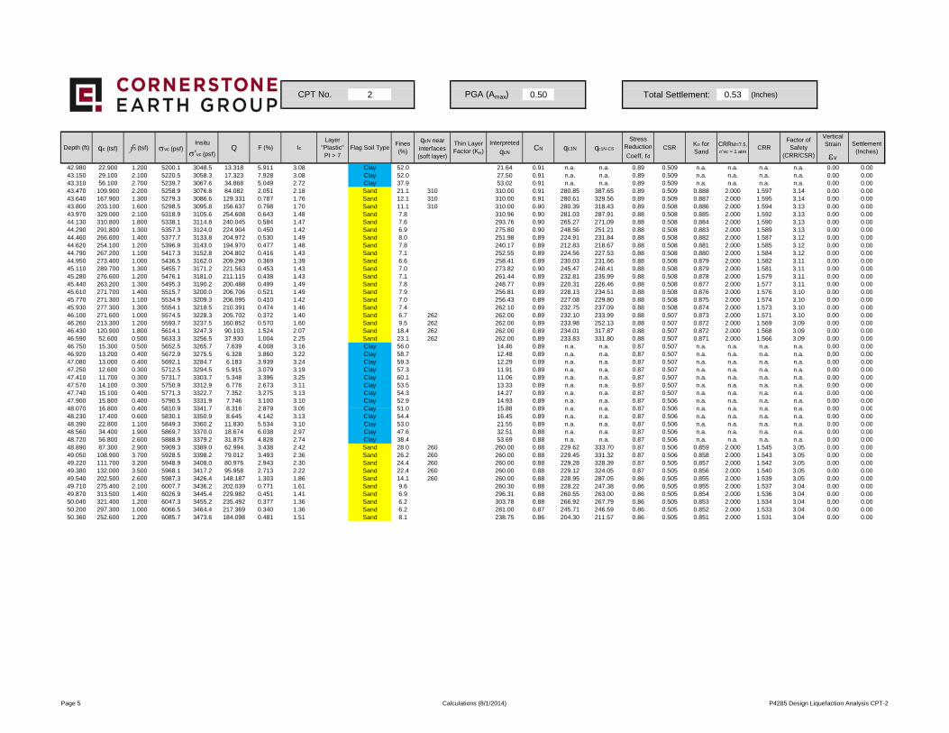
2 0.50 Total Settlement: 0.53 (Inches)
Depth (ft) qc (tsf) fs (tsf) σvc (psf)Insitu
σ'vc (psf)Q F (%) Ic
Layer "Plastic"PI > 7
Flag Soil TypeFines (%)
qcN near interfaces (soft layer)
Thin Layer Factor (KH)
Interpreted
qcNCN qc1N qc1N-CS
Stress Reduction
Coeff, rd
CSRKσ for Sand
CRRM=7.5,
σ'vc = 1 atmCRR
Factor of Safety
(CRR/CSR)
Vertical Strain
εv
Settlement (Inches)
CPT No. PGA (Amax)
42.980 22.900 1.200 5200.1 3048.5 13.318 5.911 3.08 Clay 52.0 21.64 0.91 n.a. n.a. 0.89 0.509 n.a. n.a. n.a. n.a. 0.00 0.0043.150 29.100 2.100 5220.5 3058.3 17.323 7.928 3.08 Clay 52.0 27.50 0.91 n.a. n.a. 0.89 0.509 n.a. n.a. n.a. n.a. 0.00 0.0043.310 56.100 2.700 5239.7 3067.6 34.868 5.049 2.72 Clay 37.9 53.02 0.91 n.a. n.a. 0.89 0.509 n.a. n.a. n.a. n.a. 0.00 0.0043.470 109.900 2.200 5258.9 3076.8 84.082 2.051 2.18 Sand 21.1 310 310.00 0.91 280.85 387.65 0.89 0.509 0.888 2.000 1.597 3.14 0.00 0.0043.640 167.900 1.300 5279.3 3086.6 129.331 0.787 1.76 Sand 12.1 310 310.00 0.91 280.61 329.56 0.89 0.509 0.887 2.000 1.595 3.14 0.00 0.0043.800 203.100 1.600 5298.5 3095.8 156.637 0.798 1.70 Sand 11.1 310 310.00 0.90 280.39 318.43 0.89 0.508 0.886 2.000 1.594 3.13 0.00 0.0043.970 329.000 2.100 5318.9 3105.6 254.608 0.643 1.48 Sand 7.8 310.96 0.90 281.03 287.91 0.88 0.508 0.885 2.000 1.592 3.13 0.00 0.0044.130 310.800 1.800 5338.1 3114.8 240.045 0.584 1.47 Sand 7.6 293.76 0.90 265.27 271.09 0.88 0.508 0.884 2.000 1.590 3.13 0.00 0.0044.290 291.800 1.300 5357.3 3124.0 224.904 0.450 1.42 Sand 6.9 275.80 0.90 248.56 251.21 0.88 0.508 0.883 2.000 1.589 3.13 0.00 0.0044.460 266.600 1.400 5377.7 3133.8 204.972 0.530 1.49 Sand 8.0 251.98 0.89 224.91 231.84 0.88 0.508 0.882 2.000 1.587 3.12 0.00 0.0044.620 254.100 1.200 5396.9 3143.0 194.970 0.477 1.48 Sand 7.8 240.17 0.89 212.83 218.67 0.88 0.508 0.881 2.000 1.585 3.12 0.00 0.0044.790 267.200 1.100 5417.3 3152.8 204.802 0.416 1.43 Sand 7.1 252.55 0.89 224.56 227.53 0.88 0.508 0.880 2.000 1.584 3.12 0.00 0.0044.950 273.400 1.000 5436.5 3162.0 209.290 0.369 1.39 Sand 6.6 258.41 0.89 230.03 231.66 0.88 0.508 0.879 2.000 1.582 3.11 0.00 0.0045.110 289.700 1.300 5455.7 3171.2 221.563 0.453 1.43 Sand 7.0 273.82 0.90 245.47 248.41 0.88 0.508 0.879 2.000 1.581 3.11 0.00 0.0045.280 276.600 1.200 5476.1 3181.0 211.115 0.438 1.43 Sand 7.1 261.44 0.89 232.81 235.99 0.88 0.508 0.878 2.000 1.579 3.11 0.00 0.0045.440 263.200 1.300 5495.3 3190.2 200.488 0.499 1.49 Sand 7.8 248.77 0.89 220.31 226.46 0.88 0.508 0.877 2.000 1.577 3.11 0.00 0.0045.610 271.700 1.400 5515.7 3200.0 206.706 0.521 1.49 Sand 7.9 256.81 0.89 228.13 234.51 0.88 0.508 0.876 2.000 1.576 3.10 0.00 0.0045.770 271.300 1.100 5534.9 3209.3 206.095 0.410 1.42 Sand 7.0 256.43 0.89 227.08 229.80 0.88 0.508 0.875 2.000 1.574 3.10 0.00 0.0045.930 277.300 1.300 5554.1 3218.5 210.391 0.474 1.46 Sand 7.4 262.10 0.89 232.75 237.09 0.88 0.508 0.874 2.000 1.573 3.10 0.00 0.0046.100 271.600 1.000 5574.5 3228.3 205.702 0.372 1.40 Sand 6.7 262 262.00 0.89 232.10 233.99 0.88 0.507 0.873 2.000 1.571 3.10 0.00 0.0046.260 213.300 1.200 5593.7 3237.5 160.852 0.570 1.60 Sand 9.5 262 262.00 0.89 233.98 252.13 0.88 0.507 0.872 2.000 1.569 3.09 0.00 0.0046.430 120.900 1.800 5614.1 3247.3 90.103 1.524 2.07 Sand 18.4 262 262.00 0.89 234.01 317.87 0.88 0.507 0.872 2.000 1.568 3.09 0.00 0.0046.590 52.600 0.500 5633.3 3256.5 37.930 1.004 2.25 Sand 23.1 262 262.00 0.89 233.83 331.80 0.88 0.507 0.871 2.000 1.566 3.09 0.00 0.0046.750 15.300 0.500 5652.5 3265.7 7.639 4.008 3.16 Clay 56.0 14.46 0.89 n.a. n.a. 0.87 0.507 n.a. n.a. n.a. n.a. 0.00 0.0046.920 13.200 0.400 5672.9 3275.5 6.328 3.860 3.22 Clay 58.7 12.48 0.89 n.a. n.a. 0.87 0.507 n.a. n.a. n.a. n.a. 0.00 0.0047.080 13.000 0.400 5692.1 3284.7 6.183 3.939 3.24 Clay 59.3 12.29 0.89 n.a. n.a. 0.87 0.507 n.a. n.a. n.a. n.a. 0.00 0.0047.250 12.600 0.300 5712.5 3294.5 5.915 3.079 3.19 Clay 57.3 11.91 0.89 n.a. n.a. 0.87 0.507 n.a. n.a. n.a. n.a. 0.00 0.0047.410 11.700 0.300 5731.7 3303.7 5.348 3.396 3.25 Clay 60.1 11.06 0.89 n.a. n.a. 0.87 0.507 n.a. n.a. n.a. n.a. 0.00 0.0047.570 14.100 0.300 5750.9 3312.9 6.776 2.673 3.11 Clay 53.5 13.33 0.89 n.a. n.a. 0.87 0.507 n.a. n.a. n.a. n.a. 0.00 0.0047.740 15.100 0.400 5771.3 3322.7 7.352 3.275 3.13 Clay 54.3 14.27 0.89 n.a. n.a. 0.87 0.507 n.a. n.a. n.a. n.a. 0.00 0.0047.900 15.800 0.400 5790.5 3331.9 7.746 3.100 3.10 Clay 52.9 14.93 0.89 n.a. n.a. 0.87 0.506 n.a. n.a. n.a. n.a. 0.00 0.0048 070 16 800 0 400 5810 9 3341 7 8 316 2 879 3 05 Clay 51 0 15 88 0 89 n a n a 0 87 0 506 n a n a n a n a 0 00 0 0048.070 16.800 0.400 5810.9 3341.7 8.316 2.879 3.05 Clay 51.0 15.88 0.89 n.a. n.a. 0.87 0.506 n.a. n.a. n.a. n.a. 0.00 0.0048.230 17.400 0.600 5830.1 3350.9 8.645 4.142 3.13 Clay 54.4 16.45 0.89 n.a. n.a. 0.87 0.506 n.a. n.a. n.a. n.a. 0.00 0.0048.390 22.800 1.100 5849.3 3360.2 11.830 5.534 3.10 Clay 53.0 21.55 0.89 n.a. n.a. 0.87 0.506 n.a. n.a. n.a. n.a. 0.00 0.0048.560 34.400 1.900 5869.7 3370.0 18.674 6.038 2.97 Clay 47.6 32.51 0.88 n.a. n.a. 0.87 0.506 n.a. n.a. n.a. n.a. 0.00 0.0048.720 56.800 2.600 5888.9 3379.2 31.875 4.828 2.74 Clay 38.4 53.69 0.88 n.a. n.a. 0.87 0.506 n.a. n.a. n.a. n.a. 0.00 0.0048.890 87.300 2.900 5909.3 3389.0 62.994 3.438 2.42 Sand 28.0 260 260.00 0.88 229.62 333.70 0.87 0.506 0.859 2.000 1.545 3.05 0.00 0.0049.050 108.900 3.700 5928.5 3398.2 79.012 3.493 2.36 Sand 26.2 260 260.00 0.88 229.45 331.32 0.87 0.506 0.858 2.000 1.543 3.05 0.00 0.0049.220 111.700 3.200 5948.9 3408.0 80.976 2.943 2.30 Sand 24.4 260 260.00 0.88 229.28 328.39 0.87 0.505 0.857 2.000 1.542 3.05 0.00 0.0049.380 132.000 3.500 5968.1 3417.2 95.958 2.713 2.22 Sand 22.4 260 260.00 0.88 229.12 324.05 0.87 0.505 0.856 2.000 1.540 3.05 0.00 0.0049.540 202.500 2.600 5987.3 3426.4 148.187 1.303 1.86 Sand 14.1 260 260.00 0.88 228.95 287.05 0.86 0.505 0.855 2.000 1.539 3.05 0.00 0.0049.710 275.400 2.100 6007.7 3436.2 202.039 0.771 1.61 Sand 9.6 260.30 0.88 228.22 247.38 0.86 0.505 0.855 2.000 1.537 3.04 0.00 0.0049.870 313.500 1.400 6026.9 3445.4 229.982 0.451 1.41 Sand 6.9 296.31 0.88 260.55 263.00 0.86 0.505 0.854 2.000 1.536 3.04 0.00 0.0050.040 321.400 1.200 6047.3 3455.2 235.492 0.377 1.36 Sand 6.2 303.78 0.88 266.92 267.79 0.86 0.505 0.853 2.000 1.534 3.04 0.00 0.0050.200 297.300 1.000 6066.5 3464.4 217.369 0.340 1.36 Sand 6.2 281.00 0.87 245.71 246.59 0.86 0.505 0.852 2.000 1.533 3.04 0.00 0.0050.360 252.600 1.200 6085.7 3473.6 184.098 0.481 1.51 Sand 8.1 238.75 0.86 204.30 211.57 0.86 0.505 0.851 2.000 1.531 3.04 0.00 0.00
Page 5 Calculations (8/1/2014) P4285 Design Liquefaction Analysis CPT-2