Embed Size (px)
Citation preview

BE 8253 - Basic Electrical, Electronics and instrumentation Engineering
QUESTION BANK WITH ANSWERS
Unit I (ELECTRICAL CIRCUITS)PART A
1. State Ohm’s law. (DEC 14)Ohm’s law states that the voltage (v) across a resistor is directly proportional to the current (i) flowingthrough the resistor, at constant temperature. ie, v α i ,v = iR, where R is the resistance (Ω).
2. State Kirchoff’s Current law. (MAY 13)
KCL (Kirchoff’s Current Law) states that the algebraic sum of currents entering a node(or a closed boundary) is zero. (or)The sum of the currents entering a node is equal to the sum of thecurrents leaving the node.
3. State Kirchoff’s Voltage law. (MAY 13)KVL (Kirchoff’s Voltage Law) states that the algebraic sum of all voltages around a closed path (orloop) is zero. (or) Sum of voltage drop = Sum of voltage rise.
4. An Electric iron is rated 1000W, 240V. Find the current drawn & resistance of the heating element.P=V2/R ; R= 2402/1000 = 57.6Ω and I= V/R =240/57.6 = 4.166 A
5. Define i) charge ii) electric current iii) power iv) network & v) circuit.i) Charge: Charge is an electrical property of the atomic particles of which matter consists, measured incoulombs(C ).ii) Electric current is the time rate of change of charge, measured in amperes(A). i = dq/dtA direct current (DC) is a current that remains constant with time.An alternating current (AC) is a current that varies sinusoidally with timeiii) Power is the time rate of expending or absorbing energy, measured in watts(w). p = dw/dt p- Power
in watts(w); w- energy in joules (J); t - time in seconds (S); (or) p = v i , v - Voltage in volts(V); i - currentin amperes(A);iv) Network: The inter connection of two or more simple circuit elements forms an electrical network .
v) Circuit : If the network contains at least one closed path, it is an electric circuit.
6. Define: Node (OR) Junction, Tree & branchA Node is a point in the network where two or more circuit elements are connected.TreeA Tree is a complete path including all the nodes.BranchA branch is a part of the circuit which lies between two junction points.
7. Write down the expression of equivalent resistance for ‘n’ – number of resistors in series connection.For ‘n’ resistors connected in series, the equivalent resistance is given by,
Req=R1+R2+R3+………..+Rn
8. Write down the expression of equivalent resistance for ‘n’- number of resistors in parallel connection.For ‘n’ resistors connected in parallel, the equivalent resistance is given by,
RnRRRq
1.........
3
1
2
1
1
1
Re
1
9. Write the Algorithm for Nodal Analysis.Select a node as the reference node. Assign voltages V1,V2,…Vn-1 to the remaining n-1 nodes. ApplyKCL to each of the n-1 nodes. Solve the resulting simultaneous equations to obtain the unknown nodevoltages.

10. Write the Algorithm for Mesh Analysis. (DEC, ’12)Assign mesh currents i1,i2,….in to the n meshes. Apply KVL to each of the n meshes. Solve the resulting nsimultaneous equations to get the mesh currents.
11. Apply KVL and solve (ans: I=3.54)
12. Write the Mesh equation for the circuit shown in figure.
13. Distinguish between a Loop & Mesh of a circuit (DEC, ’10)The closed path of a network is called a Loop. An elementary form of a loop which cannot be furtherdivided is called a mesh. In other words Mesh is closed path does not contain an other loop within it.
14. State Thevenins theorem. (NOV 14)It states that any linear bilateral network can be replaced by a single current source VTH, in series with
single impedance Zth
15. State Norton’s theoremIt states that any linear bilateral network can be replaced by a single current source, in parallel with
single impedance Zth.
16. State maximum power transfer theorem.Max power is transferred to load impedance if the load impedance is the complex conjugate of the sourceimpedance.
17. Sate superposition theorem.It states that the response of a linear circuit with multiple sources is given by algebraic sum of response
due to individual sources acting alone.
18. State the steps to solve the super position theorem. Take only one independent voltage or current source. Obtain the branch currents. Repeat the above for other sources. To determine the net branch current just add the current obtained above.
19. State the steps to solve the Thevenin’s Theorem Remove the load resistance and find the open circuit voltage Voc Deactivate the constant sources (fro voltage source remove it by internal resistance & for current source
delete the source by OC) and find the internal resistance (RTH) of the source side looking through theopen circuited load terminals
Obtain the thevenin’s equivalent circuit by connecting VOC in series with RTh Reconnect the load resistance across the load terminals.
Ans: 7I1 – 2I2 =10
2I1-12I2=0

20. State the steps to solve the Norton’s theorem. Remove the load resistor and find the internal resistance of the source N/W by deactivating the constant
source. Short the load terminals and find the short circuit current Norton’s equivalent circuit is drawn by keeping RTH in parallel with ISC
IL= (Isc.Rth) / (Rth+RL)
21. Write some applications of maximum power transfer theorem. Power amplifiers Communication system Microwave transmission
PART B1. Determine current in 5ohm resistor by any one method.
Soltuion.
Matrix-method for Mesh analysis can be used. Mark three loops as shown, in Fig. Resistance-matrixshould be evaluated for current in 5-ohm resistor. Only, i3 is to be found.

2. Determine the voltages 1 and 2 of the network in Fig. by nodal analysis.
3. For the circuit shown in Fig, find VCE and VAG
.
Consider the two battery circuits of Fig. separately. Current in the 20 V battery circuit ABCD is 20 (6 + 5 + 9)= 1A. Similarly, current in the 40 V battery circuit EFGH is = 40/(5 + 8 + 7) = 2A. Voltage drops overdifferent resistors can be found by using Ohm’s law.

i.e. voltage of point C with respect to point E, we will start from point E and go to C via points H and B. Wewill find the algebraic sum of the voltage drops met on the way from point E to C. Sign convention of thevoltage drops and battery e.m.fs. would be the same as discussed in Art. 2.3. For finding VCE
The positive sign shows that point A is at a positive potential of 30 V with respect to point G.
4. State and explain Kirchhoff’s laws. Determine the current supplied by the battery in the circuit shown inFig.

5. Use nodal analysis to determine the voltage across 5 ohm resistance and the current in the 12 V source.

6. State Thevenin’s theorem and give a proof. Apply this theorem to calculate the current through the 4 resistor of the circuit of Fig.
Solution.As shown in Fig. 2.130 (b), 4ohm resistance has been removed thereby open-circuiting the terminals A and B.
We will now find VAB and RAB which will give us Vth and Rrespectively. The potential drop across 5 resistorcan be found with the help of voltage-divider rule. Its value is = 155/(5 + 10) = 5 Vth
For finding VAB, we will go from point B to point A in the clockwise direction and find the algebraic sum of the voltagesmet on the way.

7. For the circuit shown in Fig. 2.135 (a), calculate the current in the 10 ohm resistance. Use Thevenin’stheorem only.
Solution. When the 10 resistance is removed, the circuit becomes as shown in Fig. 2.135 (b).
8. State Norton’s theorem and find current using Norton’s theorem through a load of 8 in the circuitshown in Fig. 2.191(a)

Solution.In Fig. 2.191 (b), load impedance has replaced by a short-circuit. ISC = IN = 200/2 = 100 A
9. In the network shown in Fig. 2.231 (a), find the value of R such that maximum possible power will betransferred to RLL. Find also the value of the maximum power and the power supplied by source under theseconditions.
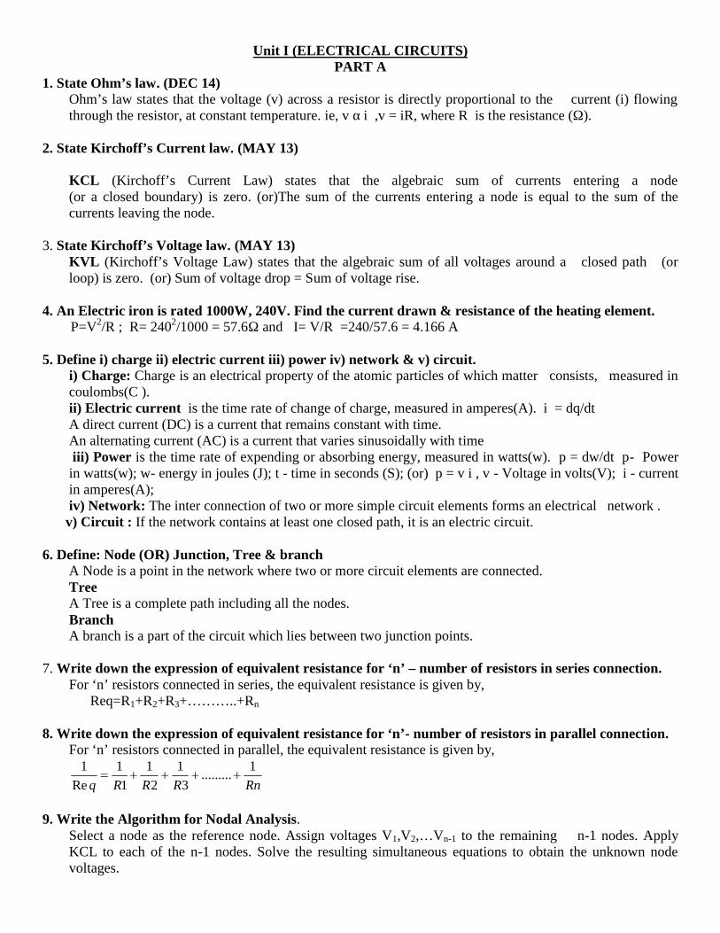
10. In the circuit shown in Fig. 2.232 (a) obtain the condition from maximum power transfer to the load RL. Hencedetermine the maximum power transferred.
Solution
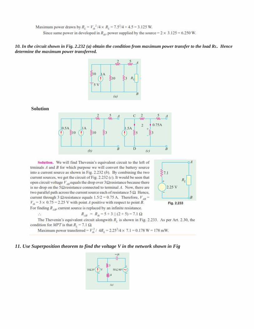
11. Use Superposition theorem to find the voltage V in the network shown in Fig

Solution. When the voltage source is killed, the circuit becomes as shown in the Fig. 15.27 (b) Using current-dividerrule,
_________________________________________________________________________

Unit II (AC CIRCUITS)PART A
1. Define Impedance.Impedance is defined as the opposition of circuit to flow of alternating current. It is denoted by Z and its unitis ohms.
2. Define Resonance.Resonance is defined as a phenomenon in which applied voltage and resulting current are in-phase. In otherwords, an AC circuit is said to be in resonance if it exhibits unity power factor condition, that means appliedvoltage and resulting current are in phase.
3. What is a Resonant frequency?The frequency at which resonance occurs is called resonant frequency. i.e. X L=XC.
4. What is the series resonance?The inductive reactance increases as the frequency increases (XL=ωl) but the capacitive reactances decreaseswith frequency(XC=1/ωc). Thus inductive and capacitive reactances have opposite properties. So, for any LCcombination there must be one frequency at which Xl=Xc. This case of equal and opposite reactance iscalled series resonance.
5. What is a parallel resonance?The parallel circuit is said to be in resonance, when the power factor is unity. This is true when the imaginarypart of the total admittance is zero.
6. Determine the power factor of a RLC series circuit with R=5ohm, XL=8ohm and XC=12ohm.(JUNE,’12)
7. What are the three types of power used in AC circuits?i) Real or Active or True power P=EI cosθ ii) Reactive power Q=EI sinθ iii)Apparent power S=EI
8. Define Real power.The actual power consumed in an AC circuits is called real power. And P=EI cosθ
9. Define Reactive power.The power consumed by the pure reactance (Xl or Xc) in an AC circuit is called reactive power. The unit isVAR. and Q=EI sinθ
10. Define Apparent power and Power factor.The Apparent power (in VA) is the product of the rms values of voltage and current. S = Vrms Irms
The Power factor is the cosine of the phase difference between voltage and current. It is also the cosine of theload impedance. And Power factor = cos φThe pf is lagging if the current lags voltage (inductive load) and is leading when the current leads voltage(capacitive load).
11. What is meant by Complex power?Complex power (in VA) is the product of the rms voltage phasor and the complex conjugate of the rmscurrent phasor. As a complex quantity, its real part is real power, P and its imaginary part is reactive power,Q. and S = P + jQ
12. What are the advantages of 3 phase circuits over single phase circuits?1. Generation, transmission and distribution of 3 phase power is cheaper 2. More efficient 3. Uniform torqueproduction occurs
13. State the relationship between line voltage & phase voltage and line current & phase current of a 3phase delta connected system.
Vph = VL ; Iph = IL / 314. State the relationship between line voltage & phase voltage and line current & phase current of a 3phase star connected system.
Vph = VL / 3; Iph = IL
15. Write the expression for the instantaneous values of emfs in a 3 phase circuit.

VR = Vm sin wt; VY = Vm sin (wt-1200); VB = Vm sin (wt-2400)16.Give some method available for measuring three-phase power.
i. Single wattmeter method. 2. Two-wattmeter method. 3. Three-wattmeter method.17.A star connected load has 6+j8 ohm impedance per phase. Determine the line current if it is connected
to 400V, three phase, and 50Hz supply. Ans: Zph=10Ω/ph, Iph= 23.094A=IL. (JUNE,’12)18. Define power factor.Power factor is defined as the cosine of angle between voltage and current. If φ is the angle between voltageand current then cos φ is called as the power factor.
19. Explain the concept of balanced load.The load is said to be balanced when magnitudes of all impedances Zph1, Zph2 and Zph3 are equal and thephase angles of all of them are equal and of same nature either all inductive or all capacitive or all resistive.
20. What is phase sequence?The order in which the voltage in the three phases reach their maximum positive values is called the phasesequence.
21. Define Phasor and Phase angle.A sinusoidal wave form can be represented or in terms of a Phasor. A Phasor is a vector with definitemagnitude and direction. From the Phasor the sinusoidal wave form can be reconstructed.Phase angle is the angular measurement that specifies the position of the alternating quantity relative to areference.
22. What are the advantages of 3Φ system?1.Constant power 2. Higher rating 3. Power transmission economics
23. Which type of connection of 3Φ system is preferred at the point of utilization? Why?Three phase , 4 wire system are used in utilization system so that either single phase or three phase load canbe connected.
24. What is house wiring?House wiring is defined as any wiring or electrical system used in a home or its surrounding areas. ... Ina home, the wiring system includes outlets, the main panel and meter base, and it is essential that allpieces are installed and function together properly to keep the home safe
25. What type of wire is used in a house?Non-Metallic Sheathed Wire (NM) This wire, commonly called Romex, is a plastic coated wire thathas either two or three conductors and a bare ground wire. This is the typical wiring used in mosthomes. The rating for this wire is either 15 amps, 20 amps, or 30 amps, depending on the installation
26. Write is meant by industrial wiring?Smart industrial wiring is based on 3-phase electrical power. 3-phase electric allows less workload to beplaced on each wire involved while at once allowing them to work together to give you maximumresults. With 3-phase electric, the wires are smaller and the motor is smaller than a typical single-phasemotor. These factors allow greater efficiency and longer lasting motors and wires.
There are four types of 3-phase electrical power: Common 3 Wire Common 4 Wire 3 Wire with Grounded Hot Leg Special 4 WireNo matter which type of 3-phase electrical power you choose to use, you’ll need a voltage meter in order todetermine the actual voltages that are available to you. The type does not determine this.Industrial wiring typically runs through metal conduits, armored cable, or a raceway. These enclosures arethe safety ground–never the neutral wire.
27. What are the materials used for wiring?

Wire Materials: The most common material for electrical wire is copper and aluminum, these are not the bestconductors however they are abundant and low cost. Gold is also used in applications because it is corrosionresistant.
Part B
1. An alternating voltage is given by V=230sin314t.Calculate i)frequency,ii)maximum value,iii)averagevalue,iv)RMS value.(N/D-2016)
Solution:
Frequency F = 1 /T =43.5 HzMaximum value Vm =Vrms/2 = 230 /2 =115 VAverage value:35.6VRMS value = Avg value / form factor =35.6 / 1.11 = 32.07 V
2. Explain about Single Phase Circuit with relevant diagrams.
Single phase circuit components:– Voltage or current sources– Impedances (resistance, inductance, and capacitance)– The components are connected in series or in parallel.• The figure shows a simple circuit where a voltage source(generator)supplies a load (resistance and inductance in series).


3. Explain about Star and Delta connected three phase balanced circuits


4. Write short notes on RMS Value of AC waveforms.
The r.m.s. value of an alternating current is given by that steady (d.c.) current which when flowing through a givencircuit for a given time produces the same heat as produced by the alternating current when flowing through the samecircuit for the same time.
It is also known as the effective or virtual value of the alternating current, the former term being used more extensively.For computing the r.m.s. value of symmetrical sinusoidal alternating currents, either mid-ordinate method or analyticalmethod may be used, although for symmetrical but non sinusoidal waves, the midordinate method would be found moreconvenient

A simple experimental arrangement for measuring the equivalent d.c. value of a sinusoidal current is shown in Fig.11.15.
The two circuits have identical resistances but one is connected to battery and the other to a sinusoidal generator. Wattmeters are used to measure heat power in each circuit. The voltage applied to each circuit is so adjusted that heat powerproduction in each circuit is the same. In that case, the direct current will equal Im/ 2 which is called r.m.s. value of thesinusoidal current.
5. Calculate the r.m.s. value, the form factor and peak factor of a periodic voltage having the followingvalues for equal time intervals changing suddenly from one value to the next : 0, 5, 10, 20, 50, 60, 50, 20, 10,5, 0, -5,-10 V etc. What would be the r.m.s value of sine wave having the same peak value ?
Solution. The waveform of the alternating voltage is shown in Fig. 11.19.
Obviously, it is not sinusoidal but it is symmetrical. Hence, though r.m.s value may be full one cycle, the average valuehas necessarily to be considered for half-cycle only, otherwise the symmetrical negative and positive half-cycles willcancel eachother out.
6. In a series circuit containing pure resistance and a pure inductance, the current and the voltage areexpressed as :
(a) What is the impedance of the circuit ? (b) What is the value of the resistance ? (c) What is the inductancein henrys ? (d) What is the average power drawn by the circuit ? (e) What is the power factor ?

7. Write a note on electrical safety
Before starting any installation work, first and foremost thing is the concern of safety of the personnel. Electricity isdangerous, direct or indirect contact of electrical equipment or wires with the power turned ON can result serious injuriesor sometimes even causes to death. Follow the below steps to maintain the safety at the workplace.
1. Always use safety equipment like goggles, gloves, shoes, etc. and avoid the direct contact with live or energizedcircuits.
2. Have the skills and techniques to distinguish the exposed live parts of the electrical equipment.3. Disconnect the source supply while installing or connecting wires.4. The power supplied to the installation must be controlled on the main switchboard which should consist of circuit
breaker.5. Conductive tools and materials must be kept at a safe distance from live parts of the circuit or equipment.6. Use non-conductive hand tools for which they are rated to perform electrical work. If they are used for voltage (or
current) rating other than rated, the insulation strength of the tool breakdown and causes electric shock.
8. What are the basic concepts of household wiring and explain?
Basic Concepts of Household WiringWiring up a house electrically can become really easy once we learn few of the fundamental points involved with it. Thefollowing simple tips may be memorized by anybody in the field and applied during wiring-up not only small houses butalso large houses or apartments:
There are basically four components involved in the whole procedure viz.: Power (Mains voltage), load, conductor,and the switch.
Normally our domestic mains power includes two paths, the incoming Phase and the outgoing or the return paththrough the Neutral. Other than these two the third conduction path in an electrical wiring is the “earth" or the ground.
Although not required with fixed appliances like lights and fans, this terminal becomes particularly imperative withthe AC outlets or the wall sockets. The top pin in a wall socket is where the earth connection is given. The “earthing" islike a huge electrical dumping ground where stray or residual current leakages are absorbed and nullified.
The bodies of potentially dangerous appliances like electric irons, geysers, refrigerators, and soldering irons tend toproduce electric shock over time on their bodies due to some portion of the phase leakage. Therefore these applianceshave their bodies connected to their plug’s “earthing" pin which ultimately gets configured with the socket’s earthingterminal once plugged in. It becomes very important that the earthing or grounding connection of every house has optimalabsorbing capacity for enabling proper absorption of these appliance body current leakages. If in doubt, consult a qualifiedelectrician and get the main ground source corrected.
The path or passage of power from phase to neutral is implemented using conductors or wires and the systemconstitutes an electrical circuit.
However, connecting the phase to neutral directly will cause havoc in the form of a big short circuit and the melting ofwires.
Therefore the right procedure is to connect a load in between these two polarities so that the power flows through theload and operates it, which actually becomes the sole intended purpose of the wiring.

But the above procedure will keep the load switched ON permanently, which can become quite undesirable andtherefore the introduction of a manually operated circuit breaking or switching device becomes imperative. For this wejust need to connect a mechanical switch in line or in series with the load and the phase- that simply solves the issue.
How to do House Wiring
Wiring a Lamp and a Switch: The diagram shows a very simple configuration which can be used for powering a lamp,and the switching arrangement is also provided in the form of a switch. This provides the basic connecting data and thesame may be used for wiring up other electrical appliances also (for example a fan).
Wiring a Lamp and a Fan in Parallel: Again the configuration employed is similar to the above and is just repeated forthe fan. The input phase and the return path neutral are common for both the electrical gadgets or rather for all appliancesthat may be further included. Note that the fan speed regulator is also a load (mostly resistive) which should be connectedin series with the fan and the switch. By adjusting the regulator knob we actually resist the flow of current into the fanthereby checking or varying its speed as desired.
Wiring up a Plug Socket: The wiring is no different from the above ones. Here the load points are just replaced with thesocket terminals, or in simple words it’s an outlet for receiving the phase and the neutral potentials through a series switchplaced in line with the phase.

Wiring up Heavier Loads: External loads like irons (presses), geysers, mixers, etc. normally have a plug and requires asocket to be plugged into, so sockets wired in the above manner can be used for powering these loads. However thesocket/switch assembly and the wires used must all be appropriately rated. The recommended standards are a 3/18 (3strands of 18 SWG each) for wires and 15 Amps for switch/socket. For smaller loads the specifications may be reduced to1/18 and 5 Amps respectively.Please note that although the above electrical house wiring layouts may look easy, there are a couple of things that needsto be taken care of. Firstly, for all configurations the switch must always come in line with the phase and before the load.Secondly the socket’s right side outlet should provide (or be connected) with the phase which again comes only afterpassing through the switch. Lastly but not the least, every house wiring system should incorporate a sound earthing linefor providing the user total safety from residual or leaking body currents from a particular appliance.
The above argument can be understood through the following straight line diagram, see carefully the current path, aftercommencing from the phase source, it enters the switch, then the load and completes the cycle by ultimately getting backto the neutral point. The third path (earth) though inactive during most occasions, sometimes becomes an importantparameter with old and over-used appliances for grounding any residual currents that may be leaking out from the bodiesof these appliances.
9. Explain the various methods of electrical wiring system.
Types of Electrical Wiring Systems
The state electricity board provides the electric supply up to the outside the consumer’s premises. The consumer has totake the connection from that point to the main switchboard at home.
From the main switchboard, various types of electrical loads such as fans, lights, room coolers, and refrigerators areconnected through the wires.There are different types of wirings used for connecting the loads to the mains which can beused for house electrical wiring as well as industrial electrical wiring. Some of these are discussed below.
Cleat Wiring
In this, porcelain, wood or plastic cleats are fixed to walls or ceilings at regularintervals, i.e., 0.6 m between each cleat. PVC insulated cables are taken throughthe holes of each cleat and hence cleat support and holds wire.

This is an inexpensive method of wiring and is used for temporary installations. Therefore, it is not suitable for homeelectrical wiring and also it is an outdated method.
Casing and Capping Wiring
In this cable is run through a wood casing having grooves. The wood casing is prepared in such a way that it isof a required fixed length with parallel grooves that accommodates the cables. The wooden casing is fixed tothe walls or ceiling with screws.
After placing the cables inside the grooves of casing, a wooden cap with grooves is placed on it to cover thecables. This is also a cheap wiring system, but there is a high risk of fire in case of short circuits.
Batten Wiring
In this, insulated wires are run through the straight teak wooden battens. The wooden battens are fixed on theceilings or walls by plugs and screws. The cables are fitted onto the battens by using tinned brass link clips.
These clips are fixed to the battens with rust-resistant nails. This wiring installation is simple and cheap ascompared to other electrical wiring systems also takes less time to install. These are mainly used for indoorinstallations.
Conduit Wiring
In this wiring, PVC cables are taken through either PVC conduit pipes or through steel conduit pipes. Thisconduit wiring can be either surface conduit wiring or concealed conduit wiring.
If the conduit pipes are run on surface of the walls and ceilings, it is called a surface conduit wiring. If theconduits are run inside the surface of the walls and ceilings and are covered with plastering, it is called asconcealed conduit wiring.
Surface conduit wiring is used in industries to connect the heavy motors. On the other hand, concealed wiring isthe most popular and common method of wiring the residential buildings. The conduit wiring is the safestmethod of wiring and also looks beautiful (concealed conduit wiring).

10. What are the various types of drawing used for electrical wiring? Explain in detail.
Types of Drawings
Electrical drawings plays an important role in electrical installation works that they convey informationabout connection of various devices and equipments with mains. The information on drawings providesthe complete design or plan of electrical installation and also helps to assemble the various equipments.
Some of the electrical wiring diagrams are discussed below. Before knowing about these diagrams, firstone must aware and have idea about various symbols used while preparing drawing and also forunderstanding the wiring connections. Check out various electrical wiring symbols .
i) Block Diagram
It is a functional drawing which shows and describes the main operating principles of the equipment ordevices. It consists of principle functions or parts represented by blocks and are connected through linesthat show the relationship between the blocks.
This diagram is usually drawn before implementing a circuit diagram. It will not give any detailedinformation about the system and also leaves the information about smaller components. And hence,most technicians have limited interest about this diagram.
ii) Circuit Drawing (Diagram)

In this, electrical circuit is graphically represented in a simplified manner. It includes the position information(in cm or m or mm) of various elements like light fixtures, receptacle boxes, junction boxes, ceiling fans, etc.
iii) Line Diagram
It is a simplified notation of an electrical system, also called as one-line diagram or single line diagram.It is similar to the block diagram except that various electrical elements such as transformers, switches,lights, fans, circuit breakers, and motors are represented by standard schematic symbols.
It consists of symbols to represent the components and lines to represent the wires or conductors whichconnects the components together.
The line diagram is actually derived from the block diagram. It doesn’t give any layout of the parts andtheir detail wiring information of the components.
However, one can do wiring by following the information given in this diagram. These diagrams areusually intended to illustrate the working of an electric circuit.
iv) Wiring Diagram
The electrical wiring diagram is a pictorial representation of the circuit which shows the wiring betweenthe parts or elements or equipments.
It gives detailed information about wiring such that one can get an idea of making connection betweenthe devices. It includes relative position, arrangement of the devices and also terminals on the devices.
It shows power supplies and earth connections, control and signal functions (with simplified shapes),termination of unused contacts and leads, interconnection via plugs, blocks, sockets, terminal posts,lead-through, etc.
11. Explain briefly the industrial wiring with neat diagram.
The wiring preparation includes the following considerations.
1. The type of conductor can be single solid wire or stranded wire conductor (which is made up of anumber of thin stands). Single solid wires are not flexible and are used where rigid connections arerequired such as power switching contractors. Mostly stranded conductors are preferred for electricalinstallations.
2. The specifications of the wire depend on the several factors like number of strands in the conductor,insulation type, cross section area of the wire, diameter of the strands, etc.

3. Choose the wires depends on the color code mentioned by various standards such as red for phase wire,black for neutral, green for earth and so on. Click here to know briefly about the electrical wiring colorsof the wires or cables.
4. Various basic electrical tools are required to do the installation work and some of these tools includecutter, strippers, testers, pliers, etc. These tools are explained in our earlier article so please check thoseelectrical tools by clicking here.
5. Choose the components such as electrical boxes, switches, receptacles, etc. based on their size andrating.Start wiring the components together by following the wiring diagrams once components, tools andcables are selected, followed by considering the safety to personnel as well as equipment.
Wiring Schedule
It is a list of cables or wires used in the installation with its reference number, length, type and theamount of insulation stripping required for soldering the cable. It gives the raceways of the wire and alsostarting and termination points.
In some complex equipment, wiring table gives the interconnection of the equipments (such as motorsand heaters) with starting and finishing reference points. It also includes the wire identificationmarkings, wire colors, size and so on.
Parts List

Although it is not a drawing, parts list is an integral part of drawing which defines the various symbolsand parts used in other drawings such as wiring diagram, line diagram, and block diagram.
It gives the information of circuit component types with related to their reference numbers. This list isuseful for identifying, locate and cross refer the actual component labeled or given in other electricaldrawings in order to ensure the choice of appropriate parts before doing the electrical wiring.
Wiring Preparation
As we are discussing the sequence of steps in wiring like understanding the safety, knowing types ofwiring systems, understanding the difference among various electrical drawings and symbols, the nextstep of electrical wiring process is the preparation of wires or cables and electrical tools.
12. Explain the followingi) Parallel wiringii) Series wiring
We know that electrical circuit is a closed path through which electricity flows from phase or hot wire tothe device or apparatus and then back the source though neutral wire.
Along the way, the electricity path may consist of fixtures, switches, receptacles, junction boxes, etc. Sothe wiring may be routed through these elements before actually making connections with apparatus ordevice.
Majorly, the wiring is divided into two types, namely parallel wiring and series wiring depending on theway the devices are powered or connected to the supply.
i ) Parallel wiring In parallel wiring, several devices on the installation are powered on a single circuit. It is the most
accepted wiring in homes and industries, in which devices are connected in parallel with the supplysource as shown in figure.
In this, both phase (or hot) and neutral cables are routed through the electrical boxes (junction boxes)from which individual receptacles, fixtures, and devices are branched.

ii) Series wiring
The series wiring is the rarely used wiring in which hot wire is routed through the several devices and thenlast device terminal is connected to the neutral wire. It is like an old Christmas lights or serial lights wiringin which one light burnout leads to the shutdown of the entire network.
13. What are the materials used for electrical wiring?
AC power plugs and sockets. Cable tray. Electrical conduit. Mineral-insulated copper-clad cable. Multiway switching. Steel wire armoured cable. Ring circuit. Thermoplastic-sheathed cable.
________________________________________________________________________________________

Unit III (ELECTRICAL MACHINES)
PART-A
1.Draw the circuit for various types of d.c motor.(N/D-2016)
Separately Excited DC Motor
DC Shunt Motor
DC Series Motor
DC Compound Motor
2.Define voltage regulation of transformer.(N/D-2016,M/J-2016)
The voltage regulation of the transformer is the percentage change in the output voltage from no-load to full-load.

3.Sketch the O.C.C of dc shunt generator.(M/J-2016)
Critical Load Resistance of Shunt Wound DC Generator
This is the minimum external load resistance which is required to excite the shunt wound generator
4.Write down the EMF equation of a transformer..(M/J-2016). E1 = 4.44*N1* f* Bm*A and E2 = 4.44*N2*f*Bm*A5.list out the types of induction motor.(N/D-2015)Induction motor types:
Polyphase cage rotor. Polyphase wound rotor.
Two-phase servo motor.
Single-phase induction motor.
Polyphase synchronous motor.
Single-phase synchronous motor.
Hysteresis synchronous motor.
6.Give some application of D.C motor.(A/M-2015,N/D-2016)Shunt :driving constant speed, lathes, centrifugal pumps, machine tools, blowers and fans, reciprocating pumpsSeries :electric locomotives, rapid transit systems, trolley cars, cranes and hoists, conveyorsCompound :elevators, air compressors, rolling mills, heavy planners
7.Why a single phase induction motor does not self start?(A/M-2015,A/M-2017,N/D-2016)When a single phase supply is fed to the single phase induction motor. Its stator
winding produces a flux which only alternates along one space axis. It is not asynchronously revolving field, as in the case of a 2 or 3phase stator winding, fed from 2or 3 phase supply.8.Mention the application of DC generator?(A/M-2017)
general lighting.

Used to charge battery because they can be made to give constant output voltage. They are used for giving the excitation to the alternators.
used for small power supply.9.What is the significance of back EMF?(A/M-2017)
When the motor is running on no load, small torque is required to overcome the friction andwindage losses. Therefore, the armature current Ia is small and the back emf is nearly equal tothe applied voltage.
If the motor is suddenly loaded, the first effect is to cause the armature to slow down. Therefore,the speed at which the armature conductors move through the field is reduced and hence the backemfEb falls. The decreased back emf allows a larger current to flow through the armature andlarger current means increased driving torque. Thus, the driving torque increases as the motorslows down. The motor will stop slowing down when the armature current is just sufficient toproduce the increased torque required by the load.
If the load on the motor is decreased, the driving torque is momentarily in excess of therequirement so that armature is accelerated. As the armature speed increases, the back emf Ebalso increases and causes the armature current Ia to decrease. The motor will stop acceleratingwhen the armature current is just sufficient to produce the reduced torque required by the load.
10.Write the principle of DC Motor?(N/D-2015)
Fleming’s left hand rule to determine the direction of force acting on the armature conductors of DC motor. If a current carrying conductor is placed in a magnetic field perpendicularly, then the conductor experiences a force in the direction mutually perpendicular to both the direction of field and the current carrying conductor. Fleming’s left hand rule says that if we extend the index finger, middle finger and thumb of our left hand perpendicular to each other, in such a way that the middle finger is along the direction of current in the conductor, and index finger is along the direction of magnetic field i.e. north to south pole, then thumb indicatesthe direction of created
11. What is the main purpose of commutator and brushes?
Commutator:The commutator converts the alternating emf into unidirectional or direct emf.
Brushes:The brushes collect the current from the commutator
12. State the principle of operation of a transformer.
Transformer operates on the principle of mutual induction between inductively coupledcoils. When A.C source is connected to one coil flux is produced in the core which links both the coils. As per the Faraday’s laws of electromagnetic induction EMF is induced in the secondary coil also. if the external circuit is closed power is supplied.
13. Write down the EMF equation of a single phase transformer.EMF induced in primary, E1= 4.44 Ø f N1 volts where
f = Frequency of supply mainØ = Flux linking both the primary and secondary winding
14. Write any two differences between single phase and three phase transformers.

i. Single phase transformer has two windings. Three phase transformer has six windings. ii. Single phasesupply is directly connected across the single primary winding where as the 3-phase transformer windings are connected in star or delta according to the design.
15. Distinguish between induction motor and synchronous motor? (A/M 2015) A three phase Synchronous motor is a doubly excited machine, whereas an induction motor is a single excited
machine. The armature winding of the Synchronous motor is energized from an AC source and its field winding from a
DC source. The stator winding of Induction Motor is energized from an AC source. Synchronous Motor always runs at synchronous speed, and the speed of the motor is independent of load, but
an induction motor always runs less than the synchronous speed. If the load increased the speed of theinduction motor decreases.
The induction motor has self-starting torque whereas the synchronous motor is not self starting. It has to be runup to synchronous speed by any means before it can be synchronized to AC supply.
16. What is the working principle of Synchronous generator?The principle of operation of synchronous generator is electromagnetic induction. If there exits a relative motion between the flux and conductors, then an emf is induced in the conductors.
17. Write the EMF equation of an alternator? (N/D-2016)
E = 4.44 x f Φ Tph voltsThis is the basic e.m.f. equation for an induced e.m.f. per phase for full pitch, concentrated type of winding. Where Tph = Number of turns per phase Tph = Zph /2 Total flux cut in one revolution is Φ x P Time taken for one revolution is 60/Ns seconds.... eavg per conductor = ΦP / (60/Ns) = Φ (PNs/60) ............. (1) But f = PNs/6120... PNs/60= 2f
18. Define voltage regulation of the alternator?It is defined as the increase in terminal voltage when full load is thrown off, assuming field current and speed remaining the same.
% reg = [(E – V)/V] x100Where E = no terminal voltage V = full load rated terminal voltage
19. What is meant by armature reaction in Alternators?The interaction between flux set up by the current carrying armature and the main is defined as the armature reaction.
20. Why a synchronous motor is a constant speed motor?Synchronous motor work on the principle of force developed due to the magnetic attraction established between the rotating magnetic field and the main pole feed. Since the speed of rotating magnetic field is directly proportional to frequency the motor operates at constant speed.
21. Name any two methods of starting synchronous motors By an extra 3 phase cage induction motor
By providing damper winding in pole phasesBy operating the pilot excitor as a dc motor
22. State the principle of 3 phase IM?While starting, rotor conductors are stationary and they cut the revolving magnetic field

and so an emf is induced in them by electromagnetic induction. This induced emf produces a current if the circuit is closed. This current opposes the cause by Lenz’s law and hence the rotor starts revolving inthe same direction as that of the magnetic field.
23. What type of single phase induction motor would you use for the followingapplications? (i) Ceiling fan (ii) Wet grinder Ceiling fan – capacitor start and run motor Wet Grinder – capacitor start motor
PART-B
1. With a neat circuit diagram Explain the construction and principle of operation of DC Motor.
(N/D-2016,N/D-2015,M/J-2017)
DC MOTOR – INTRODUCTION:A machine that converts dc power into mechanical energy is known as dc motor. Its operation is based
on the principle that when a current carrying conductor is placed in a magnetic field, the conductor experiencesa mechanical force. The direction of the force is given by Fleming’s left hand rule.WORKING OF DC MOTOR:
There are different kinds of D.C. motors, but they all work on the same principles.When a permanentmagnet is positioned around a loop of wire that is hooked up to a D.C.power source, we have the basics of aD.C. motor. In order to make the loop of wire spin, we have to connect a battery or DC power supply betweenits ends, and support it so it can spin about its axis.
To allow the rotor to turn without twisting the wires, the ends of the wire loop are connected to a set ofcontacts called the commutator, which rubs against a set of conductors called the brushes. The brushes makeelectrical contact with the commutator as it spins, and are connected to the positive and negative leads of thepower source, allowing electricity to flow through the loop. The electricity flowing through the loop creates amagnetic field that interacts with the magnetic field of the permanent magnet to make the loop spin
PRINCIPLES OF OPERATION:It is based on the principle that when a current-carrying conductor is placed in a magnetic field, it
experiences a mechanical force whose direction is given by Fleming's Left- hand rule and whose magnitude is given by
Force, F = B I l newton
Where,
B is the magnetic field in weber/m2
I is the current in amperes and
l is the length of the coil in meter
The force, current and the magnetic field are all in different directions. If an Electric current flows through two

copper wires that are between the poles of a magnet, an upward force will move one wire up and a downward force will move the other wire down.
2. Explain the construction, working principle of single phase Induction motor.(N/D-2016)
Single phase motors are very widely used in home, offices, workshops etc. as power delivered to most of thehouses and offices is single phase. In addition to this, single phase motors are reliable, cheap in cost, simple inconstruction and easy to repair.
Single phase electric motors can be classified as:
1. Single phase induction motor (Split phase, Capacitor and shaded pole etc)2. Single phase synchronous motor3. Repulsion motor etc.
Single Phase Induction Motor
CONSTRUCTION:
Construction of a single phase induction motor is similar to the construction of three phase inductionmotor having squirrel cage rotor, except that the stator is wound for single phase supply. Stator is alsoprovided with a 'starting winding' which is used only for starting purpose. This can be understood fromthe schematic of single phase induction motor at the left.
Working Principle Of Single Phase Induction Motor:
When the stator of a single phase motor is fed with single phase supply, it produces alternating flux inthe stator winding. The alternating current flowing through stator winding causes induced current in the rotorbars (of the squirrel cage rotor ) according to Faraday's law of electromagnetic induction.
This induced current in the rotor will also produce alternating flux. Even after both alternating fluxes areset up, the motor fails to start (the reason is explained below). However, if the rotor is given a initial start byexternal force in either direction, then motor accelerates to its final speed and keeps running with its ratedspeed. This behavior of a single phase motor can be explained by double-field revolving theory.
3. Describe various types self excited of DC generator with their circuit layout.(M/J-2016)

DC generators are classified based on their method of excitation. So on this basis there are two types of DC
generators:-
Self excited DC generator can again be classified as 1) DC Series generator 2) DC Shunt generator and 3) DCCompound generator.1. Separately excited DC generator
As you can guess from the name itself , this dc generator has a field magnet winding which is excitedusing a separate voltage source (like battery). You can see the representation in the below image. The outputvoltage depends on the speed of rotation of armature and field current. The higher the speed of rotation andcurrent – the higher the output e.m.f
2.Self Excited DC Generator
These are generators in which the field winding is excited by the output of the generator itself. As described before – there are three types of self excited dc generators – they are 1) Series 2) Shunt and 3) Compound.
A series DC generator is shown below in fig (a) – in which the armature winding is connected in series withthe field winding so that the field current flows through the load as well as the field winding.Field winding is a
low resistance,thick wire of few turns. Series generators are also rarely used!
A shunt DC generator is shown in figure (b), in which the field winding is wired parallel to armature windingso that the voltage across both are same. The field winding has high resistance and more number of turns so that
only a part of armature current passes through field winding and the rest passes through load.

A compound generator is shown in figure below. It has two field findings namely Rsh and Rse. They are basically shunt winding (Rsh) and series winding (Rse). Compound generator is of two types – 1) Short shunt and 2) Long shunt
Short shunt:- Here the shunt field winding is wired parallel to armature and series field winding is connected inseries to the load. It is shown in fig (1)
Long shunt:- Here the shunt field winding is parallel to both armature and series field winding (Rse is wired inseries to the armature). It is shown in figure (2)
4. Explain the characteristics of dc shunt motor.(M/J-2016)
Characteristics of DC Shunt Motor:
The three important shunt characteristic curves are
1. Torque Vs Armature current characteristic (Ta/Ia)2. Speed Vs Armature current characteristic (N/Ia)3. Speed Vs Torque characteristic (N/Ta)

The fig above shows the circuit diagram of shunt motor. In this circuit the field winding is directly connectedto the source voltage, so the field current Ish and the flux in a shunt motor are constant.
1. Torque Vs Armature current characteristic (Ta/Ia)We know that in a DC Motor Ta ∝ΦIa. In this the flux Φ is continuous by ignoring the armature reaction, since
the motor is working from a continual source voltage.
Therefore the curve drawn between torque Vs armature current is a straight line transitory through theorigin which is shown in fig. The shaft torque(Tsh) is a smaller amount than armature torque and is shown inthe fig by a dotted line. From this curve it is proved that to start a heavy load very large current is requisite.
Hence the shunt DC motor should not be started at full load.
2. Speed Vs Armature current characteristic (N/Ia)

At normal condition the back EMF Eb and Flux Φ both are constant in a DC Shunt motor. Hence the armaturecurrent differs and the speed of a DC Shunt motor will continue constant which is shown in the fig (dottedLine AB). Whenever the shunt motor load is increased Eb=V-IaRa and flux reduces as a result drop in the armature resistance and armature reaction. On the otherhand, back EMF reduces marginally more than that the speed of the shunt motor decreases to some extentwith load.
3. Speed Vs Torque characteristic (N/Ta)
This curve is drawn between the speed of the motor and armature current with various amps as shown in the fig.From the curve it is understood that the speed reduces when the load torque increases.With the above three characteristic it is clearly understood that when the shunt motor runs from no load to fullload there is slight change in speed. Thus, it is essentially a constant speed motor. Since the armature torque isdirectly proportional to the armature current, the starting torque is not high
5. Explain the tests on a single phase transformer and develop an equivalent from the above tests.(M/J-2016)
1.Open Circuit Test on TransformerThe connection diagram for open circuit test on transformer is shown in the figure. A voltmeter, wattmeter, andan ammeter are connected in LV side of the transformer as shown. The voltage at rated frequency is applied tothat LV side with the help of a variac of variable ratio auto transformer.
The HV side of the transformer is kept open. Now with the help of variac, applied voltage gets slowly increaseduntil the voltmeter gives reading equal to the rated voltage of the LV side. After reaching at rated LV sidevoltage, all three instruments reading (Voltmeter, Ammeter and Wattmeter readings) are recorded.
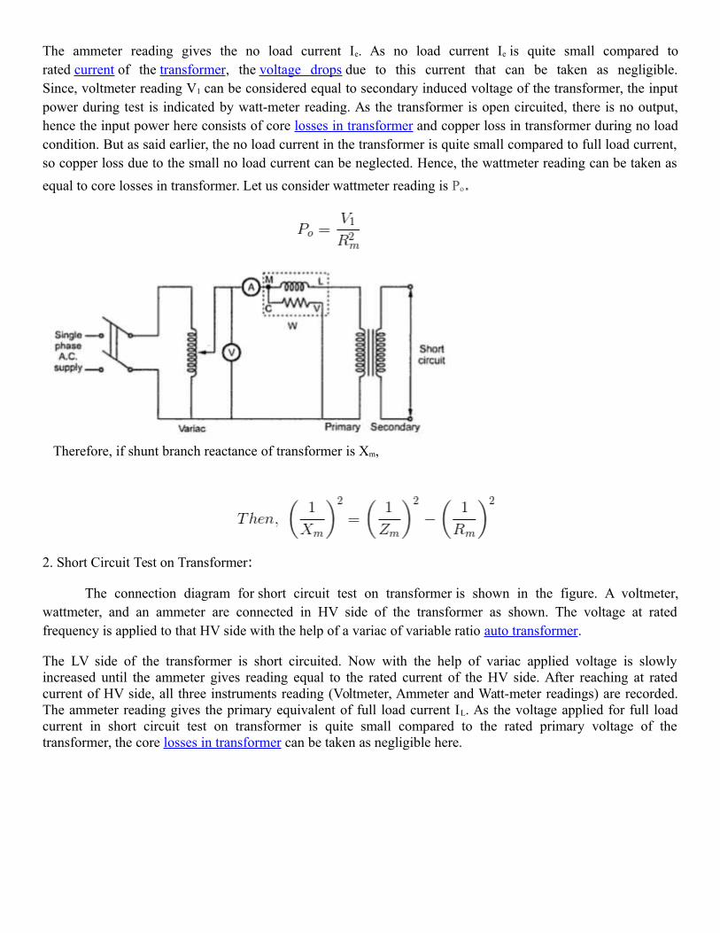
The ammeter reading gives the no load current Ie. As no load current Ie is quite small compared torated current of the transformer, the voltage drops due to this current that can be taken as negligible.Since, voltmeter reading V1 can be considered equal to secondary induced voltage of the transformer, the inputpower during test is indicated by watt-meter reading. As the transformer is open circuited, there is no output,hence the input power here consists of core losses in transformer and copper loss in transformer during no loadcondition. But as said earlier, the no load current in the transformer is quite small compared to full load current,so copper loss due to the small no load current can be neglected. Hence, the wattmeter reading can be taken as
equal to core losses in transformer. Let us consider wattmeter reading is Po.
Therefore, if shunt branch reactance of transformer is Xm,
2. Short Circuit Test on Transformer:
The connection diagram for short circuit test on transformer is shown in the figure. A voltmeter,wattmeter, and an ammeter are connected in HV side of the transformer as shown. The voltage at ratedfrequency is applied to that HV side with the help of a variac of variable ratio auto transformer.
The LV side of the transformer is short circuited. Now with the help of variac applied voltage is slowlyincreased until the ammeter gives reading equal to the rated current of the HV side. After reaching at ratedcurrent of HV side, all three instruments reading (Voltmeter, Ammeter and Watt-meter readings) are recorded.The ammeter reading gives the primary equivalent of full load current IL. As the voltage applied for full loadcurrent in short circuit test on transformer is quite small compared to the rated primary voltage of thetransformer, the core losses in transformer can be taken as negligible here.

Let’s say, voltmeter reading is Vsc. The input power during test is indicated by watt-meter reading. As thetransformer is short circuited, there is no output; hence the input power here consists of copper losses intransformer. Since, the applied voltage Vsc is short circuit voltage in the transformer and hence it is quite smallcompared to rated voltage, so core loss due to the small applied voltage can be neglected. Hence the wattmeter
reading can be taken as equal to copper losses in transformer. Let us consider wattmeter reading is Psc.
These values are referred to the HV side of transformer as because the test is conduced on HV side oftransformer. These values could easily be referred to LV side by dividing these values with square oftransformation ratio.
Therefore it is seen that the short circuit test on transformer is used to determine copper loss intransformer at full load and parameters of approximate equivalent circuit of transformer
6. Describe the construction details of single phase transformer.(A/M-2017,M/J-2017,N/D-2015,A/M-2015)
TRANSFORMER – INTRODUCTION
A TRANSFORMER is a device that transfers electrical energy from one circuit to another byelectromagnetic induction (transformer action). The electrical energy is always transferred without a change infrequency, but may involve changes in magnitudes of voltage and current. Because a transformer works on theprinciple of electromagnetic induction, it must be used with an input source voltage that varies in amplitude.There are many types of power that fit this description; for ease of explanation and understanding, transformeraction will be explained using an ac voltage as the input source. BASIC OPERATION OF A TRANSFORMER:Its most basic form a transformer consists of: A primary
Coil or winding.
A secondary coil or winding. A core that supports the coils or windings
The primary winding is connected to a 60 hertz ac voltage source. The magnetic field (flux) builds up (expands)
and collapses (contracts) about the primary winding. The expanding and contracting magnetic field around the
primary winding cuts the secondary winding and induces an alternating voltage into the winding. This voltage
causes alternating current to flow through the load. The voltage may be stepped up or down depending on the
design of the primary and secondary windings.

BASIC WORKING PRINCIPLE OF TRANSFORMERA transformer can be defined as a static device which helps in the transformation of electric power in one circuitto electric power of the same frequency in another circuit. The voltage can be raised or lowered in a circuit, but with a proportional increase or decrease in the current ratings.
The main principle of operation of a transformer is mutual inductance between two circuits which is linked by acommon magnetic flux. A basic transformer consists of two coils that are electrically separate and inductive, butare magnetically linked through a path of reluctance. The working principle of the transformer can beunderstood from the figure below
As shown above the transformer has primary and secondary windings. The core laminations are joinedin the form of strips in between the strips you can see that there are some narrow gaps right through the cross-section of the core. These staggered joints are said to be ‘imbricated’. Both the coils have high mutualinductance
Faraday’s laws of Electromagnetic Induction as
e=M*dI/dtTRANSFORMER CONSTRUCTION:
Two coils of wire (called windings) are wound on some type of core material. In some cases the coils ofwire are wound on a cylindrical or rectangular cardboard form. In effect, the core material is air and thetransformer is called an air-core transformer. Transformers used at low frequencies, such as 60 hertz and 400hertz, require a core of low- reluctance magnetic material, usually iron. This type of transformer is called aniron-core transformer. Most power transformers are of the iron-core type.

The principle parts of a transformer and their functions are:
The core, which provides a path for the magnetic lines of flux.
The primary winding, which receives energy from the ac source.
The secondary winding, which receives energy from the primary winding and delivers it
to the load.The enclosure, which protects the above components from dirt, moisture
COREThere are two main shapes of cores used in laminated-steel-core transformers. One is the
HOLLOWCORE, so named because the core is shaped with a hollow square through the center. This shape ofcore. Notice that the core is made up of many laminations of steel it shows how the transformer windings arewrapped around both sides of the core.WINDINGS
As stated above, the transformer consists of two coils called WINDINGS which are wrapped around acore. The transformer operates when a source of ac voltage is connected to one of the windings and a loaddevice is connected to the other. The winding that is connected to the source is called the PRIMARYWINDING. The winding that is connected to the load is called the secondary winding. The primary is wound inlayers directly on a rectangular cardboard form.7. Explain the different types of dc motor with neat sketch.(N/D-2016)
DC MOTOR TYPES Shunt Wound
Series Wound
Compound wound1.Shunt Motor
In shunt wound motor the field winding is connected in parallel with armature. The current through theshunt field winding is not the same as the armature current. Shunt field windings are designed to produce thenecessary m.m.f. by means of a relatively large number of turns of wire having high resistance. Therefore, shuntfield current is relatively small compared with the armature current

2.Series Motor:In series wound motor the field winding is connected in series with the armature. Therefore, series field windingcarries the armature current. Since the current passing through a series field winding is the same as the armaturecurrent, series field windings must be designed with much fewer turns than shunt field windings for the samemmf. Therefore, a series field winding has a relatively small number of turns of thick wire and, therefore, willpossess a low resistance.
3.Compound Wound Motor:Compound wound motor has two field windings; one connected in parallel withthe armature and the other in series with it. There are two types of compound motor connections
1. Short-shunt connection2. Long shunt connection
When the shunt field winding is directly connected across the armature terminals it is called short-shunt connection.
When the shunt winding is so connected that it shunts the series combination of armature and series field it is called long-shunt connection.

8. Explain the working principle of various types of single phase induction motor with neat circuit diagram.(M/J-2016)
The single phase induction motors are made self starting by providing an additional flux by some additionalmeans. Now depending upon these additional means the single phase induction motors are classified as:
1. Split phase induction motor.2. Capacitor startinductor motor.
3. Capacitor start capacitor runinduction motor (two value capacitor method).
4. Permanent split capacitor (PSC) motor .
5. Shaded pole induction motor.
1.Split Phase Induction Motor In addition to the main winding or running winding, the stator of single phase induction motor carries another winding called auxiliary winding or starting winding. A centrifugal switch is connected in series with auxiliary winding. The purpose of this switch is to disconnect the auxiliary winding from the main circuit when the motor attains a speed up to 75 to 80% of the synchronous speed.
We know that the running winding is inductive in nature. Our aim is to create the phase differencebetween the two winding and this is possible if the starting winding carries high resistance.

2.Capacitor Start IM and Capacitor Start Capacitor Run IM
The working principle and construction of Capacitor start inductor motors and capacitor start capacitorrun induction motors are almost the same. We already know that single phase induction motor is not self startingbecause the magnetic field produced is not rotating type. In order to produce rotating magnetic field there mustbe some phase difference. In case of split phase induction motor we use resistance for creating phase differencebut here we use capacitor for this purpose. We are familiar with this fact that the current flowing through thecapacitor leads the voltage. So, in capacitor start inductor motor and capacitor start capacitor runinduction motor
3. Shaded Pole Single Phase Induction Motors
The stator of the shaded pole single phase induction motor has salient or projected poles. These poles areshaded by copper band or ring which is inductive in nature. The poles are divided into two unequal halves. Thesmaller portion carries the copper band and is called as shaded portion of the pole.
ACTION: When a single phase supply is given to the stator of shaded pole induction motor an alternating fluxis produced. This change of flux induces emf in the shaded coil. Since this shaded portion is short circuited, thecurrent is produced in it in such a direction to oppose the main flux. The flux in shaded pole lags behind the fluxin the unshaded pole.

The phase difference between these two fluxes produces resultant rotating flux.We know that the stator winding current is alternating in nature and so is the flux produced by the stator current.In order to clearly understand the working of shaded pole induction motor consider three regions-
1. When the flux changes its value from zero to nearly maximum positive value.2. When the flux remains almost constant at its maximum value.
3. When the flux decreases from maximum positive value to zero.
9. Write shorts notes on the types of dc machines.(N/D-2015)TYPES OF DC MACHINES:
i) DC generatorii)DC motor
i) DC generator
An electrical generator is a rotating machine which usually converts mechanical energy into electricalenergy for doing work. The energy changing is based on the principle of electromagnetic induction. Accordingto Faraday's laws of electromagnetic induction, Whenever a conductor is feel motion in a magnetic field, emfinduced dynamically in the conductor. When an external load is connected to the conductor this inducedemfmake a current flow in the load. Thus the mechanical energy which is given in the form of movement to the conductor is converted intoelectrical energy.
Dc generators can be classified as per their methods of field excitation. There are two types of dc generatorson the basis of excitation.
Power delivered to the source is V*I(a).Separately excited Dc generators:-
If the field winding is excited by a separate dc supply from the external source, then the generator is calledseparately excited dc generators.
Self excited Dc generators:-
If the field winding energy is supplied from the armature of the generator it self, then it is called self excited dc generators. Self excited dc generators are further classified as
Series generator:-In series generator field winding is connected series to the armatureit self. The voltage generated in series field generator is E(generated)=V(terminal voltage)+I(a)*R(a)+I(se)*R(se)+V(brush).Power generated is E(g)*I(a).Shunt generator:
In shunt generator field winding is connected across the armature or parallel to the armature. The generated emf in shunt field generator is E(generated)=V(terminal voltage)+I(a)*R(a). Power generated is E(g)*I(a).Power delivered to the source is V*I(a).
Compound generator

The compound generator consists of both shunt field and series field winding on its structure. One winding is series and other is in parallel with the armature of the generator.
ii)DC Motor:
electric motors are everywhere around us. Almost all the electro-mechanical movements we see around us arecaused either by a AC or a DC motor. Here we will be exploring DC motors. This is a device that converts DCelectrical energy to a mechanical energy.
Principle of DC Motor
This DC or direct current motor works on the principal, when a current carrying conductor is placed in amagnetic field, it experiences a torque and has a tendency to move.
This is known as motoring action. If the direction of current in the wire is reversed, the direction ofrotation also reverses. When magnetic field and electric field interact they produce a mechanical force, andbased on that the working principle of DC motor is established.
The direction of rotation of a this motor is given by Fleming’s left hand rule, which states that if the indexfinger, middle finger and thumb of your left hand are extended mutually perpendicular to each other and if theindex finger represents the direction of magnetic field, middle finger indicates the direction of current, then thethumb represents the direction in which force is experienced by the shaft of the DC motor.
Structurally and construction wise a direct current motor is exactly similar to a DC generator, but electrically itis just the opposite. Here we unlike a generator we supply electrical energy to the input port and derivemechanical energy from the output port. We can represent it by the block diagram shown below.
Here in a DC motor, the supply voltage E and current I is given to the electrical port or the input port and we derive the mechanical output i.e. torque T and speed ω from the mechanical port or output port.
The input and output port variables of the direct current motor are related by the parameter K.
So from the picture above we can well understand that motor is just the opposite phenomena of a DC generator, and we can derive both motoring and generating operation from the same machine by simply reversing the ports.

Detailed Description of a DC Motor
The direct current motor is represented by the circle in the center, on which is mounted the brushes,where we connect the external terminals, from where supply voltage is given. On the mechanical terminal wehave a shaft coming out of the Motor, and connected to the armature, and the armature-shaft is coupled to themechanical load. On the supply terminals we represent the armature resistance Ra in series.
10.With a neat circuit diagram Explain the construction and principle of operation of DC Generator. (N/D-2015)
DC Generator:
A dc generator is an electrical machine which converts mechanical energy into direct current electricity. Thisenergy conversion is based on the principle of production of dynamically induced emf. This article outlinesbasic construction and working of a DC generator.
Construction of a DC generator:
A DC generator can be used as a DC motor without any constructional changes and vice versa is also possible.Thus, a DC generator or a DC motor can be broadly termed as a DC machine. These basic constructional detailsare also valid for the construction of a DC motor. Hence, let's call this point as construction of a DC machineinstead of just 'construction of a dc generator'.

The above figure shows the constructional details of a simple 4-pole DC machine. A DC machine consists two basic parts; stator and rotor. Basic constructional parts of a DC machine are described below.
1. Yoke: The outer frame of a dc machine is called as yoke. It is made up of cast iron or steel. It not onlyprovides mechanical strength to the whole assembly but also carries the magnetic flux produced by thefield winding.
2. Poles and pole shoes: Poles are joined to the yoke with the help of bolts or welding. They carry fieldwinding and pole shoes are fastened to them. Pole shoes serve two purposes; (i) they support field coilsand (ii) spread out the flux in air gap uniformly.
3. Field winding: They are usually made of copper. Field coils are former wound and placed on each poleand are connected in series. They are wound in such a way that, when energized, they form alternateNorth and South poles.
4. Armature core: Armature core is the rotor of the machine. It is cylindrical in shape with slots to carryarmature winding. The armature is built up of thin laminated circular steel disks for reducing eddycurrent losses. It may be provided with air ducts for the axial air flow for cooling purposes. Armature iskeyed to the shaft.
5. Armature winding: It is usually a former wound copper coil which rests in armature slots. Thearmature conductors are insulated from each other and also from the armature core. Armature windingcan be wound by one of the two methods; lap winding or wave winding. Double layer lap or wavewindings are generally used. A double layer winding means that each armature slot will carry twodifferent coils.
6. Commutator and brushes: Physical connection to the armature winding is made through acommutator-brush arrangement. The function of a commutator, in a dc generator, is to collect the current

generated in armature conductors. Whereas, in case of a dc motor, commutator helps in providingcurrent to the armature conductors. A commutator consists of a set of copper segments which areinsulated from each other. The number of segments is equal to the number of armature coils. Eachsegment is connected to an armature coil and the commutator is keyed to the shaft. Brushes are usuallymade from carbon or graphite. They rest on commutator segments and slide on the segments when thecommutator rotates keeping the physical contact to collect or supply the current.
Working principle of a DC generator:According to Faraday’s laws of electromagnetic induction, whenever a conductor is placed in a varying
magnetic field (OR a conductor is moved in a magnetic field), an emf (electromotive force) gets induced in theconductor. The magnitude of induced emf can be calculated from the emf equation of dc generator. If theconductor is provided with the closed path, the induced current will circulate within the path. In a DC generator,field coils produce an electromagnetic field and the armature conductors are rotated into the field. Thus, anelectromagnetically induced emf is generated in the armature conductors. The direction of induced current isgiven by Fleming’s right hand rule.
according to Fleming’s right hand rule, the direction of induced current changes whenever the direction ofmotion of the conductor changes. Let’s consider an armature rotating clockwise and a conductor at the left ismoving upward. When the armature completes a half rotation, the direction of motion of that particularconductor will be reversed to downward.
Hence, the direction of current in every armature conductor will be alternating. If you look at the above figure,you will know how the direction of the induced current is alternating in an armature conductor. But with a splitring commutator, connections of the armature conductors also gets reversed when the current reversal occurs.And therefore, we get unidirectional current at the terminals.
11. Describe the construction of an induction motor with neat diagrams. (M/J 2016)Explain the construction of three phase induction motor with neat diagram? (A/M 2017)
Construction of Induction MotorThe three phase induction motor is a preferable type of motor. It is mostly used in industrial drives
because it is very reasonable and vigorous, economical and reliable. It is also called asynchronous motor becauseit does not run at a synchronous speed. The induction motor requires very little maintenance and also it has high overloading capacity.
Construction of Stator Construction of Rotor

A three phase Induction motor mainly consists of two parts called as the Stator and the Rotor. The stator is the stationary part of the induction motor, and the rotor is the rotating part. The construction of the statoris similar to the three-phase synchronous motor, and the construction of rotor is different for the different machine. The construction of the induction motor is explained below in detail.
Construction of Stator
The stator is built up of high-grade alloy steel laminations to reduce eddy current losses. It has three main parts, namely outer frame, the stator core and a stator winding.Outer frame
Stator CoreThe stator core is built of high-grade silicon steel stampings. Its main function is to carry the alternating
magnetic field which produces hysteresis and eddy current losses. The stampings are fixed to the stator frame. Each stamping are insulated from the other with a thin varnish layer. The thickness of the stamping usually varies from 0.3 to 0.5 mm. Slots are punched on the inner side of the stampings as shown in the figure below.
Stator windingsThe core of the stator carries three phase windings which are usually supplied from a three-phase supply
system. The six terminals of the windings (two of each phase) are connected in the terminal box of the machine. The stator of the motor is wound for a definite number of poles, depending on the speed of the motor. If the number of poles is greater, the speed of the motor will be less and if the number of poles is less than the speed will be high.As the relationship between the speed and the pole of the motor is given as
The windings may be connected in start and delta.
Construction of Rotor

The rotor is also built of thin laminations of the same material as the stator. The laminated cylindrical core is mounted directly on the shaft. These laminations are slotted on the outer side to receive the conductors. There are two types of rotor.
Squirrel Cage Rotor
A squirrel cage rotor consists of a laminated cylindrical core. The circular slots at the outer periphery are semi-closed. Each slot contains uninsulated bar conductor of aluminium or copper. At the end of the rotor the conductors theshort-circuited by a heavy ring of copper or aluminium. The diagram of the cage rotor is shown below.
The rotor slots are usually not parallel to the shaft but are skewed. The skewing of the rotor conductors has thefollowing advantages given below.
It reduces humming and provide smooth and noise free operation. It results in a uniform torque curve for different positions of the rotor. The locking tendency of the rotor is reduced. As the teeth of the rotor and the stator attract each other and lock. It increases the rotor resistance due to the increased length of the rotor bar conductors. Advantages of Squirrel Cage Rotor The following advantages of the cage rotor are given below. The cage rotor is cheaper, and the construction is robust. The absence of the brushes reduces the risk of sparking. Its Maintenance is less. The power factor is higher The efficiency of the cage rotor is higher.
Phase Wound Rotor
The Phase wound rotor is also called as Slip Ring Rotor. It consists of a cylindrical core which is laminated.The outer periphery of the rotor has a semi-closed slot which carries a 3 phase insulated windings. The rotor windingsare connected in star.The slip ring induction motor is shown in the figure below.
The slip rings are mounted on the shaft with brushes resting on them. The brushes are connected to the variableresistor. The function of the slip rings and the brushes is to provide a means of connecting external resistors in the rotorcircuit. The resistor enables the variation of each rotor phase resistance to serve the following purposes given below.
It increases the starting torque and decreases the starting current. It is used to control the speed of the motor.

In this type also, the rotor is skewed. A mild steel shaft is passed through the center of the rotor and is fixed to it. Thepurpose of the shaft is to transfer mechanical power.
Advantages of Phase Wound Rotor Following are the advantages of the Phase Wound Rotor. High starting torque and low starting current. For controlling the speed of the motor, an external resistance can be added in the circuit.
12. Derive the EMF equation for the alternator? (A/M 2017)EMF Equation of a Synchronous Generator
The generator which runs at a synchronous speed is known as the synchronous generator. The synchronousgenerator converts the mechanical power into electrical energy for the grid.The Derivation of EMF Equation of asynchronous generator is given below.
Let, P be the number of poles is Flux per pole in Webersϕ N is the speed in revolution per minute (r.p.m) f be the frequency in Hertz Zph is the number of conductors connected in series per phase Tph is the number of turns connected in series per phase Kc is the coil span factor Kd is the distribution factorFlux cut by each conductor during one revolution is given as Pϕ Weber. Time taken to complete one revolution is
given by 60/N secAverage EMF induced per conductor will be given by the equation shown below
Average EMF induced per phase will be given by the equation shown below
The average EMF equation is derived with the following assumptions given below. Coils have got the full pitch. All the conductors are concentrated in one stator slot.Root mean square (R.M.S) value of the EMF induced per phase is given by the equation shown below.Eph = Average value x form factorTherefore,
If the coil span factor Kc and the distribution factor Kd , are taken into consideration than the Actual EMF induced per phase is given as
Equation (1) shown above is the EMF equation of the Synchronous Generator.

_____________________________________________________________________________________

UNIT IV ELECTRONIC DEVICES & CIRCUITS
PART-A
1. Differentiate between zener breakdown and avalanche breakdown. (AUC DEC ‘11)
Zener breakdown occurs in a reverse biased junction which gives a constant output voltage. Avalanche breakdown does not provide a constant output voltage. This constant voltage from a zener diode can be used as a reference voltage for many regulators.
2. What is peak inverse voltage? (AUC NOV’10)
The maximum reverse-bias potential that can be applied before entering the Zener region is called the peak inverse voltage (referred to simply as the PIV rating) or the peak reverse voltage (denoted by PRV rating). Peak inverse voltage is defined as the maximum reverse voltage that a diode can be subjected to operate in a reverse region so that the diode does not get damaged due to this reverse voltage
3.How do the transition region width and contact potential across a PN junction vary with the applied bias voltage? (AUC DEC’07)
The width of the PN junction is widenened for a reverse biased junction and narrows for a forward biased junction.
4. What is an ideal diode?
An ideal diode is one which offers zero resistance when forward biased and infinite resistance when reverse biased.
5. Draw the V-I characteristics of an ideal diode.
6.Draw the V-I characteristics of a practical PN diode

7. Define reverse recovery time.
It is maximum time taken by the device to switch from ON to OFF stage. 15. List the
PN diode switching times.
1. Recovery Time
2. Forward Recovery Time
3. Reverse Recovery Time
4. Reverse recovery time,
5. Storage and Transition Times
8. List some applications of zener diode
Zener diode find wide commercial and industrial applications. Some of their common applications are: As voltage regulators. As peak clippers or voltage limiters. For meter protection against damage from accidental application of
excessive voltage. As a fixed reference voltage in a network for biasing and comparison
purposes and for calibrating voltmeters. 9.Define inverting amplifier.
Inverting amplifier is one in which the output is exactly 1800 out of phase with respect to input(i.e. if you apply a positive voltage, output will be negative). Output is an inverted(in terms of phase) amplified version of input.

10.Define Non-inverting amplifier.
Non Inverting amplifier is one in which the output is in phase with respect to input(i.e. if you apply a positive voltage, output will be positive ). Output is an Non inverted(in terms of phase) amplified version of input.
PART-B
1. How a PN junction diode is working? Draw and explain V-I characteristics of PN diode with neat diagrams.
(i) PN junction diode
The semiconductor diode is formed by simply bringing these materials together (constructed from the same base—Ge or Si). At the instant the two materials are joined the electrons and holes in the region of the junction will combine, resulting in a lack of carriers in the region near the junction. This region of uncovered positive and negative ions is called the depletion region due to the depletion of carriers in
this region. Since the diode is a two-terminal device, the application of a voltage across its terminals leaves three possibilities: no bias (VD = 0 V), forward bias (VD
>0 V), and reverse bias (VD< 0 V).
PN JUNCTION NO EXTERNAL BIAS

Under no-bias (no applied voltage) conditions, any minority carriers (holes) in the n- type material that find themselves within the depletion region will pass directly into the p-type material. The closer the minority carrier is to the junction, the greater the attraction for the layer of negative ions and the less the opposition of the positive ions in the depletion region of the n-type material. Assume that all the minority carriers of the n-type material that find themselves in the depletion region due to their random motion will pass directly into the p-type material. Similar discussion can be applied to the minority carriers (electrons) of the p-type material. This carrier flow has been indicated in the above figure for the minority carriers of each material. The majority carriers (electrons) of the n-type material must overcome the attractive forces of the layer of positive ions in the n-type material and the shield of negative ions in the p- type material to migrate into the area beyond the depletion region of the p-type material. However, the number of majority carriers is so large in the n-type material that there will invariably be a small number of majority carriers with sufficient kinetic energy to pass through the depletion region into the p-type material. Again, the same type of discussion can be applied to the majority carriers (holes) of the p-type material. The resulting flow due to the majority carriers is also shown in the above figure. In the absence of an applied bias voltage, the net flow of charge in any one direction for a semiconductor diode is zero. The symbol for a diode is shown in the below figure with the associated n- and p-type regions. Note that the arrow is associated with the p-type component and the bar with the n-type region. As indicated, for VD= 0 V, the current in any direction is 0 Ma
Reverse-Bias Condition (VD < 0 V)
If an external potential of V volts is applied across the p-n junction such that the positive terminal is connected to the n-type material and the negative terminal is connected to the p-type material as shown in the below figure. The number of uncovered positive ions in the depletion region of the n-type material will increase due to the large number of free electrons drawn to the positive potential of the applied voltage. For similar reasons, the number of uncovered negative ions will increase in the p-type material. The net effect, therefore, is a widening of the depletion region. This widening of the depletion region will establish too great a barrier for the majority carriers to overcome, effectively reducing the majority carrier flow to zero as shown in the below figure.

Reverse-biased p-n junction.
The number of minority carriers, however, that find themselves entering the depletion region will not change, resulting in minority-carrier flow vectors of the same magnitude with no applied voltage the current that exists under reverse-bias conditions is called the reverse saturation current and is represented by Io
Forward-Bias Condition (VD > 0 V)
A forward-bias condition is established by applying the positive potential to the p- type material and the negative potential to the n-type material as shown in the below figure. A semiconductor diode is forward-biased when the association p-type and positive and n-type and negative has been established.
The application of a forward-bias potential VD will pressure electrons in the n-type material and holes in the p-type material to recombine with the ions

near the boundary and reduce the width of the depletion region as shown in the above figure. The resulting minority-carrier flow of electrons from the p-type material to the n-type material (and of holes from the n-type material to the p-type material) has not changed in magnitude (since the conduction level is controlled primarily by the limited number of impurities in the material), but the reduction in the width of the depletion region has resulted in a heavy majority flow across the ju nction. An electron of the n-type material now sees a reduced barrier at the junction due to the reduced depletion region and a strong attraction for the positive potential
applied to the p-type material.
2. With a neat diagram explain the working of a PN junction diode in forward bias and reverse bias and show the effect of temperature on its V-I characteristics.
Temperature Effects of pn junction diode:
Temperature can have a marked effect on the characteristics of a silicon semiconductor diode as shown in the below figure. It has been found experimentally that the reverse saturation current Io will just about double in magnitude for every

10°C increase in temperature.
It is not uncommon for a germanium diode with an Io in the order of 1 or 2 A at 25°C
to have a leakage current of 100 A _ 0.1 mA at a temperature of 100°C. Typical
values of Io for silicon are much lower than that of germanium for similar power and current levels. The result is that even at high temperatures the levels of Io for silicon diodes do not reach the same high levels obtained for germanium—a very important reason that silicon devices enjoy a significantly higher level of development and utilization in design. Fundamentally, the open-circuit equivalent in the reverse bias region is better realized at any temperature with silicon than with germanium. The increasing levels of Io with temperature account for the lower levels of threshold voltage. Simply increase the level of Io in and not rise in diode current. Of course, the level of TK also will be increase, but the increasing level of Io will overpower the smaller percent change in TK. As the temperature increases the forward characteristics are actually becoming more ideal.
3.Write Short notes on operational amplifier.
Op Amps Applications
Audio amplifiers
Speakers and microphone circuits in cell phones, computers, mpg players,
boom boxes, etc.
Instrumentation amplifiers
Biomedical systems including heart monitors and oxygen sensors.
Power amplifiers

Analog computers
Combination of integrators, differentiators, summing amplifiers, and
multipliers
Terminals on an Op Amp
Typical Op Amp Parameters
Parameter Variable Typical Ranges Ideal Values
Open-Loop
Voltage Gain
A 105 to 108 ∞
Input Resistance Ri 105 to 1013 W ∞ W
Output Resistance Ro 10 to 100 W 0 W

Supply Voltage Vcc/V+
-Vcc/V-
5 to 30 V
-30V to 0V
N/A
N/A
Component Datasheets Many manufacturers have made these freely available on the internet Example: LM 324 Operational Amplifier
4. Explain the construction and working of BJT.
A bipolar (junction) transistor (BJT) is a three-terminal electronic device constructed of doped semiconductor material and may be used in amplifying or switching applications. Bipolar transistors are so named because their operation involves both electrons and holes. Charge flow
in a BJT is due to bidirectional diffusion of charge carriers across a junction between two regions
of different charge concentrations. An NPN transistor can be considered as two diodes with a shared anode. In typical operation, the base-emitter junction is forward biased and the base– collector junction is reverse biased. In an NPN transistor, for example, when a positive voltage is applied to the base–emitter junction, the equilibrium between thermally generated carriers and
the repelling electric field of the depletion region becomes unbalanced, allowing thermally excited electrons to inject into the base region. These electrons wander (or "diffuse") through the base from the region of high concentration near the emitter towards the region of low concentration near the collector. The electrons in the base are called minority carriers because the base is doped p-type which would make holes the majority carrier in the base.
To minimize the percentage of carriers that recombine before reaching the collector–base junction, the transistor's base region must be thin enough that carriers can diffuse across it in much less time than the semiconductor's minority carrier lifetime. In particular, the thickness of the base must be much less than the diffusion length of the electrons. The collector–base junction is reverse-biased, and so little electron injection occurs from the collector to the base, but electrons that diffuse through the base towards the collector are swept into the collector by the electric field in the depletion region of the collector–base junction. The thin shared

base and asymmetric collector–emitter doping is what differentiates a bipolar transistor from two separate and oppositely biased diodes connected in series.
Transistor 'alpha' and 'beta'
The proportion of electrons able to cross the base and reach the collector is a measure of the BJT efficiency. The heavy doping of the emitter region and light doping of the base region cause many more electrons to be injected from the emitter into the base than holes to be injected from the base into the emitter. The common-emitter current gain is represented by βF or hfe; it is approximately the ratio of the DC collector current to the DC base current in forward-active
region. It is typically greater than 100 for small-signal transistors but can be smaller in transistors designed for high-power applications. Another important parameter is the common-base current gain, αF. The common-base current gain is approximately the gain of current from emitter to collector in the forward-active region. This ratio usually has a value close to unity; between 0.98 and 0.998. Alpha and beta are more precisely related by the following identities (NPN
transistor):
Fig Simplified cross section of a planar NPN bipolar junction transistor
A BJT consists of three differently doped semiconductor regions, the emitter region, the base region and the collector region. These regions are, respectively, p type, n type and p type in a PNP, and n type, p type and n type in a NPN transistor. Each semiconductor region is connected to a terminal, appropriately labeled: emitter (E), base (B) and collector (C).

The base is physically located between the emitter and the collector and is made from lightly doped, high resistivity material. The collector surrounds the emitter region, making it almost impossible for the electrons injected into the base region to escape being collected, thus making the resulting value of α very close to unity, and so, giving the transistor a large β. A cross section view of a BJT indicates that the collector–base junction has a much larger area than the emitter– base junction.
Small changes in the voltage applied across the base–emitter terminals causes the current that flows between the emitter and the collector to change significantly. This effect can be used to amplify the input voltage or current. BJTs can be thought of as voltage-controlled current source, but are more simply characterized as current-controlled current sources, or current amplifiers,
due to the low impedance at the base.
NPN
The symbol of an NPN Bipolar Junction Transistor.
NPN is one of the two types of bipolar transistors, in which the letters "N" (negative) and "P" (positive) refer to the majority charge carriers inside the different regions of the transistor. Most bipolar transistors used today are NPN, because electron mobility is higher than hole mobility in semiconductors, allowing greater currents and faster operation. NPN transistors consist of a layer of P-doped semiconductor (the "base") between two N-doped layers. A small current entering the base in common-emitter mode is amplified in the collector output. In other terms, an NPN transistor is "on" when its base is pulled high relative to the emitter. The arrow in the NPN transistor symbol is on the emitter leg and points in the direction of the conventional current flow when the device is in forward active mode.
PNP
The other type of BJT is the PNP with the letters "P" and "N" referring to the majority charge carriers inside the different regions of the transistor.

The symbol of a PNP Bipolar Junction Transistor.
PNP transistors consist of a layer of N-doped semiconductor between two layers of P-doped material. A small current leaving the base in common-emitter mode is amplified in the collector output. In other terms, a PNP transistor is "on" when its base is pulled low relative to the emitter. The arrow in the PNP transistor symbol is on the emitter leg and points in the direction of the conventional current flow when the device is in forward active mode.
Regions of operation
Applied voltages Mode
E < B < C Forward active
E < B > C Saturation
E > B < C Cut-off
Bipolar transistors have five distinct regions of operation, defined by BJT junction
biases. The modes of operation can be described in terms of the applied voltages (this
description
applies to NPN tranistors; polarities are reversed for PNP transistors):
Forward active: base higher than emitter, collector higher than base (in this mode the
collector current is proportional to base current by βF).
Saturation: base higher than emitter, but collector is not higher than base.
Cut-Off: base lower than emitter, but collector is higher than base. It means the transistor
is not letting conventional current to go through collector to emitter.

In terms of junction biasing: ('reverse biased base–collector junction' means Vbc < 0 for NPN, opposite for PNP)
Forward-active (or simply, active): The base–emitter junction is forward biased and the base–collector junction is reverse biased. Most bipolar transistors are designed to afford the greatest common-emitter current gain, βF, in forward-active mode. If this is the case, the collector–emitter current is approximately proportional to the base current, but many times larger, for small base current variations.
Saturation: With both junctions forward-biased, a BJT is in saturation mode and facilitates high current conduction from the emitter to the collector. This mode corresponds to a logical "on", or a closed switch.
Cutoff: In cutoff, biasing conditions opposite of saturation (both junctions reverse
biased) are present. There is very little current, which corresponds to a logical "off", or an open switch.
Bipolar Transistor Construction
The construction and circuit symbols for both the NPN and PNP bipolar transistor are shown above with the arrow in the circuit symbol always showing the direction of conventional current flow between the base terminal and its emitter terminal, with the direction of the arrow pointing from the positive P-type region to the negative N-type region, exactly the same as for the standard diode symbol.
5. Explain CB configuration with the help of input and output characteristics.

There are basically three possible ways to connect a Bipolar Transistor within an electronic circuit with each method of connection responding differently to its input signal as the static characteristics of the transistor vary with each circuit arrangement.
1. Common Base Configuration - h a s Voltage Gain but no Current Gain.
2. Common Emitter Configuration - has both Current and Voltage Gain.
3. Common Collector Configuration - h a s Current Gain but no Voltage Gain.
The Common Base Configuration.
As its name suggests, in the Common Base or Grounded Base configuration, the BASE connection is common to both the input signal and the output signal with the input signal being applied between the base and the emitter terminals. The corresponding output signal is taken from between the base and the collector terminals as shown with the base terminal grounded or connected to a fixed reference voltage point. The input current flowing into the emitter is quite large as its the sum of both the base current and collector current respectively therefore, the collector current output is less than the emitter current input resulting in a Current Gain for this type of circuit of less than "1", or in other words it "Attenuates" the signal.
The Common Base Amplifier Circuit
This type of amplifier configuration is a non-inverting voltage amplifier circuit, in that the signal voltages Vin and Vout. This type of arrangement is not very common due to its unusually high voltage gain characteristics. Its Output characteristics represent that of a forward biased diode while the Input characteristics represent that of an illuminated photo-diode. Also this type of configuration has a high ratio of Output to Input resistance or more importantly

6. BJT Characterstics Explain?
To become familiar with the theory of operation of bipolar junction transistors (BJT) and to examine the V-I characteristics of BJT's
The transistor type (NPN or PNP) can be determined using a multimeter. The test checks the polarity of the base-emitter and base-collector junctions. This test is to be performed at the beginning of the lab session. For the BJT, there are three regions of operation;
1. Active region: In this region, the base emitter junction is forward biased and the base-collector junction is reverse biased. This region is the normal transistor operation mode for amplification, and is characterized by the transistor current gain value, beta.
2. Cut-off region: In this region, both base-emitter and base-collector junctions are reverse biased and the transistor acts like an open switch. (IC = 0)
3. Saturation region: In this region, both base emitter and base-collector junctions are forward biased and the transistor acts like a closed switch. (VCE = 0)
In the active region of the transistor, a figure of merit has been defined to quantify the capability of the transistor to amplify the input signal. This parameter is defined as the ratio between IC to IB and typically called the β factor. Similarly an α factor is defined as the ratio between IC to IE. Thus;
β = IC / IB and α = IC / IE
It can be easily shown that β = α /(1 - α) and α = β /(β + 1). As a rule of thumb, the larger the value of β, the higher the gain obtainable from the transistor, i.e. the better the transistor. Typical values for β ranges from about 80 to 300 or higher.

7. Explain in detail about inverting amplifier.
Definition
Inverting amplifier is one in which the output is exactly 1800 out of phase with respect to input(i.e. if you apply a positive voltage, output will be negative). Output is an inverted(in terms of phase) amplified version of input.
Circuit operation
The inverting amplifier using opamp is shown in the figure below

Assuming the opamp is ideal and applying the concept of virtual short at the input terminals of opamp, the voltage at the inverting terminal is equal to non inverting terminal. The simplified circuit is shown in the figure below
Applying KCL at inverting node we get
(0-Vi)/Ri+(0-Vo)/Rf = 0
By rearranging the terms we will get
Voltage gain Av = Vo/ Vi = – Rf/Ri .
Gain
Gain of inverting amplifier Av= – Rf/Ri.
8. Explain in detail about non inverting amplifier.
Definition
Non Inverting amplifier is one in which the output is in phase with respect to input(i.e. if you apply a positive voltage, output will be positive ). Output is an Non inverted(in terms of phase) amplified version of input.
Circuit operation
The inverting amplifier using opamp is shown in the figure below

Assuming the opamp is ideal and applying the concept of virtual short, the voltage at the inverting terminal is equal to non inverting terminal. Applying KCL at inverting node we get
(Vi-Vo)/R2+(Vo-0)/R1 = 0
By rearranging the terms we will get
Voltage gain Av = Vo/ Vi = (1+ Rf/Ri)
Gain
Gain of non inverting amplifier Av= (1+ Rf/Ri).
9. Explain in detail about ADC.

10. Explain in detail about DAC.
Connecting digital circuitry to sensor devices is simple if the sensor devices are inherently digital themselves. Switches, relays, and encoders are easily interfaced with gate circuits due to the on/off nature of their signals. However, when analog devices are involved, interfacing becomes much more complex. What is needed is a way to electronically translate analog signals into digital (binary) quantities, and vice versa. An analog-to-digital converter, or ADC, performs the former task while a digital-to-analog converter, or DAC, performs the latter.
An ADC inputs an analog electrical signal such as voltage or current and outputs a binary number. In block diagram form, it can be represented as such:

A DAC, on the other hand, inputs a binary number and outputs an analog voltage or current signal. In block diagram form, it looks like this:

UNIT-5 MEASUREMENT AND INSTRUMENTATION1.Mention 2 disadvantages of capacitive transducer? (May-11)
Output impedance of capacitive transducer is very high. So its measuringcircuit becomes very complicated.
The capacitance of capacitive transducer change with change in temperatureor account of Presence of small external matter.
Example: dust particles, moisture.
2.Write the function of transducer (May-11)It converts one type of energy into another.3..Define inverse transducer with example (May-10)
An inverse transducer is defined as device which converts an electrical quantity into anon electrical quantity. It is a precision actuator which has an electrical input and a low power non electricaloutput.
4.Mention any 4 types of analog to digital convertor? (May-10) Flash type of convertor Staircase convertor Tracking convertor Successive approximation type
5.What is the need of sample and hold circuit in A/D convertor? (Dec-10)
Sample and hold circuits are the devices that store analog information and reduce theaperture time of an A/D convertor
A sample hold is a simply a voltage memory device in which an input voltage isacquired and then stored on a high quality capacitor.
6.Define the primary and secondary transducers? (May2010) Primary Transducer:
When the input signal is directly sensed by the transducer and physicalphenomenon is converted into electrical form directly then such a transducer is called theprimary transducer.Secondary Transducer:
When the input signal is sensed first by some detector or sensor and then itsoutput being of some from other than input signals is given as input to a transducer forconversion into electrical form, then such a transducer falls in the category of secondarytransducers.
7..State the performance parameters of ADC (May 2010) Resolution. Quantization error. Conversion time.
8..How do you classify transducers? (Dec 2010) On the basis of transduction form used. As primary and secondary transducers.

As active and passive transducers. As analog and digital transducers. As transducers and inverse transducers.
9..What is piezo-electric effect? (Dec 2010)
A piezoelectric material is one in which an electric potential appears across certainsurfaces of the crystal if the dimensions of the crystals are changed by the application of amechanical force this potential is produced by the displacement of charges .This effect is reversible.This phenomenon is known as piezoelectric effect.
10.Explain the working principle of capacitive transducers? (Dec 2010)
The principle of capacitive transducer is based on the familiar equation of capacitance ofparallel plate capacitor.
C= ε A /d11.What are the selection criteria for the transducer? (Jun 2009)
Operating range.Sensitivity. Environmental conditions Errors. Accuracy.
12.What is meant by strain gauge? What for it is used? (Jun 2009)
It is an example of a passive transducer that uses the variation in electrical resistance inwires to sense the strain produced by a force on the wires.
13.What is POT? It is active or passive transducer? (Dec 2006) POT is a resistive potentiometer used for the purpose of voltage division. It consists for a resistive element provided with a sliding contact called as wiper. The POT is a passive transducer since it requires an external power source for itsoperation.
14.Name the transducer that uses sensing acceleration? (Jun 2006, May2005) Piezo-electric transducer.
15.Write any four basic requirements of transducer? (Dec 2004) RUGGEDNESS: It should be capable for withstanding overload. LINEARITY: The input-output characteristics should be linear.
NO HYSTERISIS: It should not give any hysteresis during measurement while inputsignal isvaried from low to high value and vice versa.
RESIDUAL DEFORMATION: There should be no deformations on removal of loadafter long period of time
16. Define current transformer& Potential transformer?

A current transformer (CT) is a type of transformer that is used to measure alternatingcurrent (AC). It produces a current in its secondary which is proportional to the current in itsprimary. ... The current transformer presents a negligible load to the primary circuitPotential transformer Voltage transformers (VT), also called potential transformers (PT), are a parallelconnected type of instrument transformer. They are designed to present negligible load to thesupply being measured and have an accurate voltage ratio and phase relationship to enableaccurate secondary connected metering.
PART-B
1. Explain in detail about classifications of transducer.TRANSDUCERS
ØTheinputquantityformostinstrumentationsystemsisnonelectrical.Inordertouseelectricalmethodsandtechniquesformeasurement,thenonelectricalquantityisconvertedintoaproportionalelectricalsignalbyadevicecalledtransducer.
ØAnotherdefinitionstatesthattransducerisadevicewhichwhenactuatedbyenergyinonesystem,suppliesenergyinthe sameformorinanother formtoasecond system.
ØWhentransducergivesoutputinelectricalformitisknownaselectricaltransducer.Actually,electricaltransducerconsistsoftwopartswhichareverycloselyrelatedtoEachother.
ØThesetwopartsaresensingordetectingelementandtransductionelement.Thesensingordetectingelementiscommonlyknownassensor.
ØDefinitionstatesthatsensorisadevicethatproducesameasurableresponsetoaChangeina physicalcondition.
Ø Thetransductionelementtransformstheoutputofthesensortoanelectricaloutput,asshownintheFig.
Classification ofElectricalTransducersTransducersmaybeclassifiedaccording totheirstructure,methodofenergy
conversionandapplication.ThuswecansaythattransducersareclassifiedAsactiveand passive transducerAccordingtotransductionprincipleAsanaloganddigitaltransducerAsprimaryand secondarytransducerAstransducerandinverse transducer

ActiveandPassiveTransducerActiveTransducers
Ø Active transducersareself-generatingtypeoftransducers.Ø These transducers developanelectricalparameter(i.e.voltage or current)whichis
proportionaltothequantityundermeasurement.Ø Thesetransducers donotrequireanyexternalsourceorpowerfortheiroperation.
Ø Theycanbesubdividedintothefollowingcommonlyused types
Passive TransducersØ Passivetransducersdonotgenerateanyelectricalsignalbythemselves.
Ø Toobtainanelectricalsignal fromsuchtransducers,anexternalsourceofpoweris essential.Ø Passive transducers
dependuponthechangeinanelectricalparameter(R,L,orC).Ø Theyarealsoknownasexternallypowerdriventransducers.Ø Theycan besubdividedintothe followingcommonlyusedtypes.
According to TransductionPrincipleThetransducerscan beclassifiedaccordingto principleusedin transduction.
CapacitivetransductionElectromagnetictransductionInductive transduction

PiezoelectrictransductionPhotovoltaictransductionPhotoconductivetransduction
Analog and DigitalTransducersThe transducers can beclassifiedonthe basisofthe
outputwhichmaybeacontinuousfunctionoftimeortheoutputmaybeindiscretesteps.
AnalogTransducers
Ø Thesetransducersconverttheinputquantityintoananalogoutputwhichisa continuousfunction oftime.Ø Astraingauge,LVDT,thermocouplesorthermistorsarecalledanalogtransducersastheyproduceanoutp
whichis acontinuousfunctionoftime.
DigitalTransducersØ Digitaltransducersproduceanelectricaloutputinthe formofpulses
whichformsanuniquecode.Ø Unique codeisgeneratedforeachdiscretevaluesensed.
Primary orSecondaryØ Sometransducers consistof mechanical devicealongwiththeelectricaldevice.
Ø Insuchtransducersmechanical deviceactsasaprimarytransducerandconvertsphysicalquantityintomechanical signal.
Ø Theelectricaldevicethenconverts mechanicalsignal producedbyprimarytransducerintoanelectricalsignal.
Ø Therefore,electricaldeviceactsasasecondarytransducer.Ø Foranexample,inpressuremeasurementBourdonstubeacts as
aprimarytransducerwhichconverts a pressureintodisplacementandLVDTacts asasecondarytransducer whichconvertsthisdisplacementintoanequivalentelectricalsignal.
Pressure Measurement
Transducer and Inverse TransducerØ Transducersconvertnon-
electricalquantityintoelectricalquantitywhereasinversetransducerconvertselectricalquantit

yintonon-electricalquantity.Ø Forexample,microphoneis atransducerwhichconvertssoundsignalintoan
electricalsignalwhereasloudspeakerisaninversetransducerwhichconvertselectricalsignalintosoundsignal.
2. Explain in detail about merits, demerits and characteristics of transducer.Advantages Transducers
1. Electricalsignalobtainedfromelectricaltransducer canbe easilyprocessed(mainlyamplified)andbroughttoalevel suitablefor outputdevice whichmaybeanindicatororrecorder.2. The electricalsystemscan be controlledwithaverysmall levelof power3. The electricaloutputcan beeasilyused,transmitted,andprocessedforthepurposeof
measurement.4. WiththeadventofIC technology,theelectronicsystemshavebecomeextremelysmallinsize,requiringsmallspacefortheiroperation.5. Nomovingmechanicalpartsareinvolvedin theelectricalsystems.Thereforethereisnoquestionofmechanicalwearandtearandnopossibilityofmechanicalfailure.Electricaltransducerisalmostamustinthismodemworld.Apartfromthemeritsdescribedabove,some disadvantages doexistin electricalsensors.
Disadvantagesof ElectricalTransducersØ Theelectricaltransducerissometimeslessreliable
thanmechanicaltypebecauseoftheageinganddriftofthe active components.Ø Also,thesensingelementsandtheassociated signalprocessing circuitryare
comparativelyexpensive.
Ø Withtheuseofbettermaterials,improved technologyandcircuitry,therangeofaccuracyandstabilityhavebeenincreasedforelectricaltransducers.
ØUsingnegativefeedbacktechnique,theaccuracyof measurementandthe stabilityofthesystemareimproved,butallattheexpenseofincreasedcircuitcomplexity,morespace,andobviously,morecost.
CharacteristicsofTransducer
1. Accuracy:Itis defined as the closenesswithwhich the readingapproachesanacceptedstandardvalueoridealvalueortruevalue,ofthevariablebeingmeasured.
2. Ruggedness:Thetransducershouldbemechanicallyruggedtowithstandoverloads.Itshouldhave overloadprotection.
3. Linearity:Theoutput ofthetransducershouldbelinearlyproportionaltotheinputquantityundermeasurement.Itshouldhavelinearinput-outputcharacteristic.-
4. Repeatability:Theoutputofthetransducermustbeexactlythesame,undersameenvironmentalconditions,whenthesamequantityisapplied attheinputrepeatedly.
5. Highoutput:Thetransducershouldgivereasonablyhighoutputsignalsothatitcanbeeasilyprocessedandmeasured.The outputmustbemuchlargerthannoise.Now-a-days,digitaloutputispreferredinmanyapplications;
6. High Stabilityand Reliability:The output ofthe transducer shouldbehighly

stableandreliableso that therewillbeminimumerror inmeasurement.Theoutputm
ustremainunaffectedbyenvironmentalconditionssuchaschangeintemperature,pressure,etc.
7. Sensitivity: The sensitivityof theelectricaltransducerisdefinedastheelectricaloutputobtainedperunitchangeinthephysicalparameter oftheinputquantity.Forexample,foratransducerusedfortemperaturemeasurement,sensitivitywillbe expressedinmV/’C.Ahighsensitivityisalways desirableforagiventransducer.
8. DynamicRange:Foratransducer,theoperatingrangeshouldbewide,sothatitcanbeusedovera wide rangeof measurementconditions.
9. Size:Thetransducershouldhavesmallestpossiblesizeandshapewithminimalweightandvolume.Thiswillmakethemeasurementsystem verycompact.
Speed ofResponse:Itis therapiditywithwhichthe transducerresponds tochangesinthemeasuredquantity.The speedofresponse ofthe transducershouldbeashighas practicable.
3. Explain the selection criteria of transducer in detail.
1. Nature of measurement2. Loading effect3. Environmental considerations4. Measuring system5. Cost &Availability
In a measurement system the transducer (or a combination of transducers) is the inputelement with the critical function of transforming some physical quantity to a proportionalelectrical signal. So selection of an appropriate transducer is most important for havingaccurate results.
The first step in the selection procedure is to clearly define the nature of quantity undermeasurement (measurand) and know the range of magnitudes and frequencies that themeasurand is expected to exhibit. Next step will be to examine the available transducerprinciples for measurement of desired quantity. The type of transducer selected must becompatible with the type and range of the quantity to be measured and the output device.
In case one or more transducer principles are capable of generating a satisfactory signal,decision is to be taken whether to employ a commercially available transducer or build asuitable transducer. If the transducers are available in the market at a suitable price, thechoice will probably be to purchase one of them, otherwise own transducer will have to bedesigned, built and calibrated.
The points to be considered in determining a transducer suitable for a specific measurementare as follows:

Range. The range of the transducer should be large enough to encompass all the expectedmagnitudes of the measurand.
Sensitivity. The transducer should give a sufficient output signal per unit of measured inputin order to yield meaningful data.
Electrical Output Characteristics. The electrical characteristics-the output impedance, thefrequency response, and the response time of the transducer output signal should becompatible with the recording device and the rest of the measuring system equipment.
Physical Environment. The transducer selected should be able to withstand theenvironmental conditions to which it is likely to be subjected while carrying outmeasurements and tests.
Such parameters are temperature, acceleration, shock and vibration, moisture, andcorrosive chemicals might damage some transducers but not others.
Errors. The errors inherent in the operation of the transducer itself, or those errors causedby environmental conditions of the measurement, should be small enough or controllableenough that they allow meaningful data to be taken.
However the total measurement error in a transducer-activated system may be reduced tofall within the required accuracy range by adopting the following techniques.
4. Draw and explain resistive transducer in detail.
ResistanceTransducers
Temperature SensorsTemperatureisone ofthefundamentalparametersindicatingthephysicalconditionof
matter,i.e.expressingitsdegree ofhotnessorcoldness.Wheneverabodyisheat’variouseffectsareobserved.Theyinclude
Changeinthephysicalorchemical state,(freezing,melting,boilingetc.)Changeinphysicaldimensions,Changesinelectricalproperties,mainlythechangeinresistance,Generationofan emfatthejunctionoftwodissimilarmetals.
Oneoftheseeffectscanbeemployedfortemperaturemeasurementpurposes.Electricalmethodsarethemostconvenientandaccuratemethodsoftemperaturemeasurement.Thesemethodsarebasedonchangeinresistancewithtemperatureandgenerationofthermale.m.f.Thechangeinresistancewithtemperaturemaybepositiveornegative.Accordingtothatthereare twotypes
ResistanceThermometers —PositivetemperaturecoefficientThermistors—Negative temperaturecoefficient
Constructionof ResistanceThermometersØ The wireresistancethermometer usuallyconsistsofacoilwound
onamicaorceramicformer, asshowninthe Fig.Ø
Thecoiliswoundinbifilarformsoastomakeitnoinductive.Suchcoilsareavailableindifferentsizesandwithdifferentresistancevaluesrangingfrom10ohms to25,000ohms.

ResistanceThermometers1. Themeasurementis accurate.
2. Indicators,recorderscanbe directlyoperated.3. The temperature sensorcanbeeasilyinstalledandreplaced.4. Measurementofdifferentialtemperatureispossible.5. Resistancethermometerscanwork overawide rangeoftemperaturefrom
-20’Cto+650°C.6. Theyare suitableforremote indication.7. Theyaresmallerinsize8. They have stabilityoverlongperiodsoftime.
5. Draw and explain capacitive transducer in detail. Also mention its applications. Capacitive sensor is of non-contact type sensor and is primarily used to measure the linear
displacements from few millimeters to hundreds of millimeters. It comprises of threeplates, with the upper pair forming one capacitor and the lower pair another. The lineardisplacement might take in two forms:
one of the plates is moved by the displacement so that the plateseparation changes
area of overlap changes due to the displacement.

The capacitance C of a parallel plate capacitor is given by, C = εr εo A / d
where εr is the relative permittivity of the dielectric between the plates, εo permittivity of freespace, A area of overlap between two plates and d the plate separation.
As the central plate moves near to top plate or bottom one due to the movement of theelement/workpiece of which displacement is to be measured, separation in between theplate changes. This can be given as,
C1 = (εr εo A) / (d + x) C2 = (εr εo A) / (d – x) When C1 and C2 are connected to a Wheatstone’s bridge, then the resulting out-of-balance
voltage would be in proportional to displacement x.APPLICATIONS
Feed hopper level monitoring Small vessel pump control Grease level monitoring Level control of liquids Metrology applications
6. Draw and explain Piezo electric transducer in detail.

Piezoelectric sensor is used for the measurement of pressure, acceleration and dynamic-forces such as oscillation, impact, or high speed compression or tension.
It contains piezoelectric ionic crystal materials such as Quartz.On application of force orpressure these materials get stretched or compressed.
During this process, the charge over the material changes and redistributes. One face of the material becomes positively charged and the other negatively charged. The
net charge q on the surface is proportional to the amount x by which the charges have beendisplaced. The displacement is proportion to force. Therefore we can write,
7. Draw and explain digital storage oscilloscope.
DigitalStorageOscilloscope
BlockDiagram
Theblock diagram ofdigitalstorage oscilloscopeis shownintheFig.
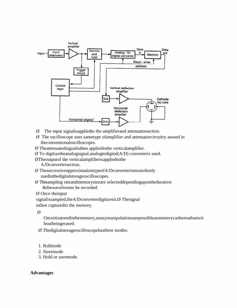
Ø The input signalisappliedto the amplifierand attenuatorsection.Ø The oscilloscope uses sametype ofamplifier and attenuatorcircuitry asused in
theconventionaloscilloscopes.Ø Theattenuatedsignalisthen appliedtothe verticalamplifier.Ø To digitizetheanalogsignal,analogtodigital(A/D) converteris used.ØTheoutputof the verticalamplifierisappliedtothe
A/Dconvertersection.Ø ThesuccessiveapproximationtypeofA/Dconverterismostoftenly
usedinthedigitalstorageoscilloscopes.Ø Thesampling rateandmemorysizeare selecteddependingupontheduration
&thewaveformto be recorded.Ø Once theinputsignalissampled,theA/Dconverterdigitizesit.Ø Thesignalisthen capturedin the memory.
ØOnceitisstoredinthememory,manymanipulationsarepossibleasmemorycanbereadoutwithoutbeingerased.
Ø Thedigitalstorageoscilloscopehasthree modes:
1. Rollmode2. Storemode3. Hold or savemode.
Advantages

i) Itiseasierto operate and has more capability.ii) Thestorage timeisinfinite.iii) Thedisplayflexibilityisavailable.Thenumberoftracesthatcanbestoredandrecalleddepends on thesizeofthememory.iv) The cursor measurementispossible.v) The characterscanbe displayed onscreenalong withthe waveformwhich
canindicatewaveforminformation such as minimum, maximum,frequency,amplitude
etc.vi) TheX-Y plots,B-Hcurve,P-Vdiagramscanbe displayed.vii) The pretriggerviewingfeature allows todisplaythewaveformbeforetriggerpulse.viii) Keepingthe recordsispossible bytransmittingthedatato computersystemwherethe
furtherprocessingispossibleix) Signalprocessingispossiblewhichincludestranslatingtherawdataintofinishedinformati
one.g.computingparametersof acaptured signallike r.m.s.value, energystored etc.
8. Draw and explain CRT display in detail.Thedevicewhichallows, the
amplitudeofsuchsignals,tobedisplayedprimarilyasafunctionoftime,iscalledcathoderayoscilloscope.Thecathoderaytube(CRT)istheheartoftheC.R.O.TheCRTgeneratestheelectronbeam,acceleratesthebeam,deflectsthebeamandalsohasascreenwherebeambecomesvisibleasaspot. Themainpartsof the CRT are
i) Electron gunii) Deflection systemiii) Fluorescent screeniv) Glasstubeorenvelopev) Base

Electron gunØ
Theelectrongunsectionofthecathoderaytubeprovidesasharplyfocused,electronbeamdirectedtowardsthefluorescent-coated screen.
Ø Thissectionstarts fromthermallyheated cathode, emittingtheelectrons.Ø Thecontrol gridisgivennegativepotentialwithrespecttocathode.Ø Thisgrid controlsthenumberof electronsin tbeam,goingto thescreen.Ø
Themomentumoftheelectrons(theirnumberxtheirspeed)determinestheintensity,orbrightness,ofthelightemittedfromthe fluorescentscreen dueto the electronbombardment.

Ø Thelight emittedisusuallyofthegreencolour.DeflectionSystem
Ø Whentheelectronbeamisaccelerateditpassesthroughthedeflectionsystem,withwhichbeamcanbepositionedanywhereonthe screen.FluorescentScreen
ØThelightproducedbythescreendoesnotdisappearimmediatelywhenbombardmentbyelectronsceases, i.e., when the signal becomes zero.
ØThetimeperiodforwhichthetraceremainsonthescreenafterthesignalbecomeszeroisknown as“persistenceor fluorescence”.
Ø Thepersistencemaybeasshortasafewmicrosecond,oraslongastensofsecondsorevenminutes.
Ø Medium persistence tracesaremostlyusedforgeneralpurposeapplications.Ø Longpersistencetraces are usedin thestudyoftransients.
ØLongpersistencehelpsinthestudyoftransientssincethetraceisstillseenonthescreenafterthetransienthasdisappeared.
GlassTubeØ Allthe components ofaCRTare enclosedin an evacuatedglasstubecalledenvelope.Ø Thisallowstheemittedelectronstomoveaboutfreelyfromoneendofthetubetothe
otherend.
BaseØ Thebaseisprovidedto the CRT throughwhich the connections9.Explain in detail about current transformer transformer?Instrument TransformersInstrument Transformers
• It is a transformer that is used in conjunction with any measuring instrument (i.e., Ammeter,Voltmeter, Wattmeter, Watt-hour-meter, …etc.)or protective equipment (i.e., Relays).
• It utilizes the current-transformation and voltage transformation properties to measure high accurrent and voltage.
Types of instrument transformers :These instrument transformers are of two types:-
1. Current transformers2. Potential transformers
Applications of Instrument Transformers:• For measurement of high ac current, it is usual to use low range ac ammeter with suitable shunt.• For measurement of high ac voltage, low range ac voltmeters are used with high resistances
connected in series.• For measurement of very high ac current and voltage, we cannot use these methods. Instead, we
use specially constructed HV instrument transformers to insulate the high voltage circuit from themeasuring circuit in order to protect the measuring instruments from burning.
• Application of Instrumentation Transformers In dc circuits for current and voltage measurement,we use low range dc ammeters and voltmeters with rectifiers connected in their secondarycircuits.
• The vast primary application of Instrument Transformers is for the protection and control of

power system and power equipment of high and very high ratings.• The working of these instrument transformers are similar to those of the ordinary transformers.
Current TransformersWhat is current Transformer (CT)
• A current transformer is a transformer, which produces in its secondary winding low current,which is proportional to the high current flowing in its primary winding.
• The secondary current is usually much smaller in magnitude than the primary current.• The design of CT depends on which type of instrument is connected to its secondary winding.
Measuring instrument OR Protective instrument.-Measuring instrument CT is expected to give accurate results up to a maximum of 125% of its
normal full-load rated current.-Protective instrument CT is expected to be accurate for up to 20 times of its normal full-load rated
current (about 2000% of its full-load rated current!!..??).• Based on the type of equipment for which the Ct is used for, its saturation point will vary. At the
same time it is expected to be linear in the entire working range.Construction of C.T.:

• C.T. has a primary coil of one or more turns made of thick wire connected in series with the linewhose current is to be measured.
• The secondary consists of a large number of turns made of fine wire and is connected across anammeter or a relay’s terminals.
Function of CT:• The principal function of a CT is to produce a proportional current at a level of magnitude, which
is suitable for the operation of low-range measuring or protective devices such as indicating orrecording instruments and relays.
• The primary and secondary currents are expressed as a ratio such as 100/5 or 1000/5 .With a 100/5 ratio CT, 100A flowing in the primary winding will result in 5A flowing in thesecondary winding, provided that the correct rated burden is connected to the secondary winding
10. Explain in detail about potential transformer?Potential Transformers:What is a Potential Transformer (PT) or (VT)?:
• A PT or sometimes called VT is a step-down transformer having many primary turns but fewsecondary turns.
• In a step-down transformer the voltage decreases and the current increases, thus voltage can beeasily measured by using a low-range voltmeter instrument.
• The voltage is stepped-down in a known ratio called the voltage ratio.Construction and working of P.T.:Construction
• A potential transformer has many primary winding turns but few number of secondary windingturns that makes it a step-down transformer.
• A Voltmeter is connected to the secondary winding is usually a voltmeter of 150 V.Working (Measurement):
• Primary terminals are connected in parallel across the line to which the voltage is to be measured.• The voltmeter reading gives the transformed value of the voltage across the secondary terminals.• The deflection of the voltmeter when divided by the transformed ratio gives the actual voltage
across the primary winding as:The Line voltage = deflection / transformation-Ratio
Where transformation ratio = V2/V1Precaution for P.T.:
• Since the secondary of a p.t. is connected to relays, their ratings are usually 40 to 100 Watts.

• For safety purpose the secondary should be completely insulated from the high voltage primaryand should be in addition grounded.
Types of P.T. :Some types of p.t. are:
• Shell type• Dry type• Oil type
Rating Type1. Below 5000 v Shell type2. 5000-13800 v Dry type and oil type3. Above 13800 v only oil type