Embed Size (px)
Citation preview

QUESTIONS REPORTfor HLT-29 rebuttal Questions
01 4A4.04 001/2/2/RPI/MEM 2.7/2.7/3NEW/FA0 11 005/RO/
Question 20:-
Unit 2 is starting up the reactor after a reactor trip. DRPI shows all rods on the bottomand the step counters show the At Power rod positions prior to the reactor trip.
(AW UOP-1.3, Startup of Unit following an At Power Reactor Trip, the ROD CONTROLSTARTUP RESET switch on the MCB is taken to the RESET position. Which one ofthe following will result from this action?
Av The Bank Overlap Unit will indicate zero.
B. FF3, DRPI Urgent Failure, annunciator will come into alarm.
C. FF1, Rod Cont Urgent Failure, annunciator will come into alarm.
D. Rod Insertion Limit computer will generate a rod position Lo and Lo-Lo alarm.
A. Correct - The Bank Overlap Unit will indicate zero.This is one of six actions that occur when the ROD CONTROL STARTUP RESET
switch on the MCB is taken to the RESET position.
B. Incorrect - This alarm could be confused with the Rod Cont Urgent Failureannunciator.
C. Incorrect - This alarm will clear, not come in to alarm, if in alarm and the conditioncorrected when the ROD CONTROL STARTUP RESET switch is taken to theRESET position.
D. Incorrect - This is a correct answer if the ROD CONTROL STARTUP RESET switchon the MCB is taken to the RESET position while at 100% power.
Prior to doing a reactor startup, all counters should be set to zero, and any urgent failuresshould be cleared. The rod control startup reset switch on the MCB performs the following sixfunctions:1. Resets the step counters on MCB to zero.2. Resets the master cycler 0-5 counter to zero (This will ensure correct group action.)3. Resets the slave cyclers 0-127 counters to zero (This will ensure correct sequence ofa step.)4. Resets the bank overlap unit 0-999 counter to zero (This will ensure correct bankoverlap.)5. Resets all urgent failure alarms if the conditions have been corrected.6. Resets the pulse-to-analog convertors in the rod position indication system to zero(This will ensure correct insertion limit surveillance.)
Tuesday, January 25, 2005 1:04:02 PM I

QUESTIONS REPORTfor HLT-29 rebuttal Questions
014A4.04 Ability to manually operate and/or monitor in the control room:
Re-zeroing of rod position prior to startup
Explain the purpose and operation including the design features and functions,capacities,and protective interlocks of the following major component associated with the Rod
Control System (OPS40204102):*Rod Control Startup Reset Switch
POSITION:
During a normal shutdown, GRPI step counters are run down to zero along with the
P-A converter. At C- 14, the RIL Lo and Lo-Lo alarms will come into alarm. During the
subsequent startup, when the ROD CONTROL STARTUP RESET switch is placed in
RESET position, these alarms will NOT actuate since they are already in alarm (in
solid) and due to the fact that the P-A converter is already at zero and the step
counters are also at zero steps.
When a reactor trip occurs, the GRPI counters and the P-A converter will be at the last
known rod position. In this condition the the RIL Lo and Lo-Lo alarms will NOT be in
alarm due to the P-A converter is still indicating rods at the post trip condition and the
RIL computer determining the limit to be at the zero power limit of C-1 14.
During the subsequent reactor startup when the ROD CONTROL STARTUP RESET
switch is placed in RESET position, the RIL Lo and Lo-Lo alarms will come into alarm
since the the P-A converter is reading D-230 and is being reset to zero telling the RIL
computer the rods at zero steps (indicating that the control banks are at zero steps)
and the computed RIL being at the zero power limit of "C" at 114 steps.
This question is asked from the standpoint that the GRPI counters are at the full
power position and apparently no other actions have been completed because GRPI is
not reset. One has to assume that the rod position Lo and Lo-Lo alarms are NOT in at
this time due to the above discussion. This would be expected for a Rx trip recovery
since GRPI is in the at power position. Therefore the alarms WILL come into alarm
when the ROD CONTROL STARTUP RESET switch is placed in RESET position.
Answer "A" was chosen as the correct response on the key because it is a direct action
listed in the lesson plans which result from resetting the ROD CONTROL STARTUP
RESET switch. Resetting the ROD CONTROL STARTUP RESET switch performs the
following actions as listed in the lesson plan:
1. Resets the step counters on MCB to zero.2. Resets the master cycler 0-5 counter to zero (This will ensure correct
group action.)3. Resets the slave cyclers 0-127 counters to zero (This will ensure correct
Tuesday, January 25, 2005 1:04:02 PM 2

QUESTIONS REPORTfor HLT-29 rebuttal Questions
sequence of a step.)4. Resets the bank overlap unit 0-999 counter to zero (This will ensure
correct bank overlap.)5. Resets all urgent failure alarms if the conditions have been corrected.
6. Resets the pulse-to-analog (P to A) converters in the rod position
indication system to zero (This will ensure correct insertion limitsurveillance.)
RECOMMENDATION:
We recommend to NRC change the key to answer "A" and "D" as being correct.
Hypothesis of why the exam team missed this on review.This question was initially written as being at 100% power and the ROD CONTROL
STARTUP RESET switch is taken to the RESET position, what will happen?
During the validation process the validators commented that this was a 5 level of
hardness. This question was changed several times and the final date of print was Oct
27. The question was then validated and reviewed and we missed that fact.
Tuesday, January 25, 2005 1:04:02 PM 3

the condition is cleared, the urgent failure can be cleared by depressing the rod control alarm reset
push button on the MCB, or by locally resetting the urgent failure alarm at the logic or power
cabinets. Rod Control Startup Reset Switch
Prior to doing a reactor startup, all counters should be set to zero, and any urgent failures
should be cleared. The rod control startup reset switch on the MCB perfonns the following six
functions:
1. Resets the step counters on MCB to zero.
2. Resets the master cycler 0-5 counter to zero (This will ensure correct group action.)
3. Resets the slave cyclers 0-127 counters to zero (This will ensure correct sequence of
a step.)
4. Resets the bank overlap unit 0-999 counter to zero (This will ensure correct bank
overlap.)
5. Resets all urgent failure alarms if the conditions have been corrected.
6. Resets the pulse-to-analog convertors in the rod position indication system to zero
(This will ensure correct insertion limit surveillance.)
The rod control startup reset switch should not be used unless all rods are on the bottom.
Power Cabinet Non- Urezent Failure
A power cabinet non-urgent failure will be caused by a loss of any one of four DC power
supply modules in the power cabinet (main and auxiliary, +24 and -24V DC). This may be due to
low line voltage, a blown fuse, or failure of the module's AC supply. If only one of each redundant
pair fails, the other will continue supplying the cabinet's DC circuits through a blocking diode
arrangement. The non-urgent failure does not affect rod motion.
A power cabinet non-urgent failure will annunciate the ROD CONTROL NON-URGENT
FAILURE alarm on the MCB. The alarm will automatically clear when the non-urgent failure
clears.
The +24V DC power supplies have status lights on the front of the power cabinets (PS I and
PS2). These status lights must be checked within one hour of receiving the ROD CONTROL
NON-URGENT FAILURE alarm. If both status lights are not lit, then at least one +24V DC power
supply must be reset within one hour or rod drops may occur due to a depleted backup battery.
Logic Cabinet Non-Urgent Failure
26 OPS-52201E/ 4020411 ESP-52201EM

11/18/0412:32:41 UJL i t FNP-1-UOP-1.3
NOTE: All surveillance reviews, whether it is for the nightly review or for a Modechange, should be performed in an environment free from distractions. It is theresponsibility of the person performing the review, and the person performingthe verification to establish such an environment (including moving to an emptyoffice if necessary) before commencing the task, and to ensure they are notdistracted from the task. (IR 1-95-297)
* It is intended that the following step be completed within a reasonable timeframe, however, it is not meant to be a stopping point until it is completed. Theoperating crew should perform this step in parallel with the remainder of this
rocedure.
5.6.5 Verify a Weekly STP Schedule list of Operations STPs required for
/ Modes 3, 2 and I exists. IF required, THEN review the OperationsSSS Surveillance Schedules and prepare a Weekly STP Schedule list of
Operations STPs required for Modes 3, 2 and I for the next 7 day
/ period. Following verification, provide this list to the Shift
SSS Supervisor.
5.6.6 Ensure that no MODE 2 LCOs exist./
*5.7 IF reactor decay heat diminishes to the point where gland seal can NOT be
/ maintained, THEN place auxiliary steam on Unit 2 per FNP- I -SOP-55. 1,AUXILIARY STEAM AND CONDENSATE SYSTEM, and gland seal onauxiliary steam per FNP-1-SOP-28.4, GLAND SEALING STEAM SYSTEM. IF
necessary, THEN place a hogger in operation, FNP-1-SOP-28.5, CONDENSERAIR REMOVAL SYSTEM.
NOTE: IF less than 2 reactor coolant pumps are running in Mode 3, THEN the rodcontrol system shall be disabled for rod withdrawal.
5.8 WHEN all reactor trip conditions have cleared, TIHEN perform the following:
5.8.1 Verify reactor trip breakers closed.
l
5.8.2 Reset Rod Control Start-up Reset switch.l
5.8.3 Verify Bank Overlap Unit is reset to 0.
5.8.4 Withdraw shutdown banks A and B.
Page 10 of 29 Version 50.0

I --A Y F- so
11/18/04 12:32:41 FNP-1-UOP-1 .3
NOTE: WHEN the reactor is critical, the low low Tavg Alarm shall be verified reset (RXCOOLANT LOOPS IA, 1B or iC TAVG LO-LO annunciator HF4) AND allRCS Loop Tavg shall be verified greater than or equal to 5470F, OR eachreactor coolant loop Tavg shall be verified greater than or equal to 541FF every30 minutes per FNP-1-STP-35.1, UNIT STARTUP TECHNICALSPECIFICATION VERIFICATION. (Technical Specification 3.4.2)
3.27 On FNP-1-STP-35. 1, UNIT STARTUP TECHNICAL SPECIFICATIONVERIFICATION, record time of criticality, the temperature of last observedlowest reading Tavg prior to criticality and the time of the observation
3.28 Smoothed SUR is useful in anticipating the trend in reactor power and RCSTAVG especially when there is a positive moderator temperature coefficient. Theexpected moderator temperature coefficient can be obtained by referring to Curve5. It is important to remember that while using smoothed SUR to anticipatetrends, the actual parameters to be controlled are reactor power level and RCSaverage temperature. Appropriate response to control temperature must be takeneven if smoothed SUR does not show a change. {CMT 0009899}
3.29 Correct operation of the SGFP speed control system is very important for propersteam generator water level control system operation. Ensure feed header tosteam header AP is being maintained at the correct program value.{CMT 0009899}
NOTE: AVG changes affect NI indicated power but do not affect AT indicated power.Consider TAVG value when comparing NI and AT indications. (IR 1-94-118)
*Thermal streaming should simultaneously affect all three AT loops in a similarway -- if only a single loop AT deviates from calorimetric power or is markedlydifferent from the other loops, an instrumentation problem may be indicated.
3.30 WHEN reactor power is in the power range, THEN compare reactor powerindications and check for agreement. Continue monitoring and checking foragreement during the subsequent reactor power ascension. (IR 1-94-118)
* Average of RCS ATs
* Average of Power Range NIs
* AFW flow requirements (rough estimate of power level)
* Steam dump or S/G Atmospheric relief valve demand (rough estimate ofpower level)
3.30.1 IF any power disagreement greater than 2% is indicated, THEN' resolve
the discrepancy prior to power ascension.
3.31 Resetting the ROD CONTROL STARTUP RESET switch resets the following:Bank Overlap Unit, Master Cycler, Slave Cyclers, Pulse-to-analog converters,Urgent Failure Alarms, and Step Counters.
Page 5 of 29 Version 50.0

RTESP UNIT I CYCLE 20 AUGUST 2004
Fully Withdrawn - 225 to 231 steps, inclusive
225
200
175
B 150E
la
c 125
C0
' 1000
C-
cmm
'a 750
--- F-T- lII II IIIII1 (.552, 225)1 :1 2ILA I I- -- - (1,187)
-- Bank C..
I I I I- -I.I-- - -FTT A II
( ,11 ) -I -I- -- -I-I
Bank-
+H++H+ -7 7 .FT
(.070, 0)Ji-
SO
25
00.0 0.1 0.2 0.3 0.4 0.5 0.6 0.7 0.8 0.9 1.0
Fraction of RATED THERMAL POWER
Fully Withdrawn shall be the condition where control rods are at a position within the interval Ž 225 and< 231 steps withdrawn.
Note: The Rod Banik Insertion Limits are based on the control bank withdrawal sequence A, 13, C, I) anda control bank tip-to-tip distance of 128 steps.
Page 9 of 12

11'18/04 12:16:43V,--; ; T t -1 -1 r
A IL FNP- I -ARP- 1.6
LOCATION FEI
SETPOINT: Variable; 10 Steps Greater than LO-LO AlarmSetpoint.ZLO = ZLO-LO + K4Where K4 = 10 Steps (6.25 inches)
ORIGIN: Rod Insertion Limit Computer
ElCONT ROD
BANKPOSITION
LO
PROBABLE CAUSE
NOTE: Zinc Addition System injection will result in a continuous RCS dilution ofmuch as 1.7 gph, which may result in a reduction in shutdown margin ifcompensated for by inward rod motion instead of boration.
* This annunciator has REFLASH capability.
Reactor Coolant System Boric Acid Concentration too low forReactor Power Level due to:A. Plant TransientB. Xenon TransientC. Dilution of RCS
AUTOMATIC ACTION
NONE
OPERATOR ACTION
1. Check indications and determine that actual control bank rodposition is at low insertion limit.
2. IF reactor coolant system dilution is in progress,THEN stop dilution.
3. IF a plant transient is in progress,THEN place the turbine load on "HOLD".
4. Refer to FNP-I -UOP-3. 1, POWER OPERATIONS.5. Borate the Control Bank "OUT" as necessary using the Boron
Addition Nomographs. {CMT 0008900)6. Refer to the Technical Specifications section on Reactivity
Control.
References: A-177100, Sh. 291; U-260610; U266647 PLS Document; Technical SpecificationsDCP 93-1-8587; {CMT 0008554, 0008887)
Page I of I Version 44.0

I '& I-XF-P -FNP-1-ARP-I.611/18/04 12:16:43
LOCATION FEI
SETPOINT: Variable; 10 Steps Greater than LO-LO AlarmSetpoint.ZLO Z-Lo + K4
Where K4 = 10 Steps (6.25 inches)
ElCONT ROD
BANKPOSITION
LO
ORIGIN: Rod Insertion Limit Computer
PROBABLE CAUSE
NOTE: e Zinc Addition System Injection will result In a continuous RCS dilution of asmuch as 1.7 gph, which may result in a reduction in shutdown margin ifcompensated for by inward rod motion instead of boration.
a This annunciator has REFLASH capability.
Reactor Coolant System Boric Acid Concentration too low forReactor Power Level due to:A. Plant TransientB. Xenon TransientC. Dilution of RCS
AUTOMATIC ACTION
NONE
OPERATOR ACTION
1. Check indications and determine that actual control bank rodposition is at low insertion limit.
2. IF reactor coolant system dilution is in progress,THEN stop dilution.
3. IF a plant transient is in progress,THEN place the turbine load on "HOLD".
4. Refer to FNP-1-UOP-3.1, POWER OPERATIONS.5. Borate the Control Bank "OUT" as necessary using the Boron
Addition Nomographs. {CMT 0008900)6. Refer to the Technical Specifications section on Reactivity
Control.
References: A-177100, Sh. 291; U-260610; U266647 PLS Document; Technical SpecificationsDCP 93-1-8587; {CMT 0008554, 0008887)
Page I of I Version 44.0

FedEx I Ship Manager I Label 7915 4807 3383 Page I of I
From: OCgn ID: (334)8144517ALABAMA POWER -FARLEYNUCLEARSOLIHEFN NUCLEAR PLANT FAREYHIGHWAY 95 SOUTH
COLUMBIA, AL 36319
Ship Date: 11FEB05Fe &h . Adual Wgt: 1 LB
MMr System#: 32693241INET2000
_9 A r~: S .........
A re 73427520040NG1 j10tEMT
CER Dehivery Address E ar CodeSHIPTO: (404)52464 BILLSEND
Ron AlelloU.S. Nuclear Regulatory CommissionAtlanta Federal Center, Region 1161 Forsyth St., SW Suite 23T85Atlanta, GA 30303
STANDARD OVERNIGHT MONDeliver By:
FORM 14FEB05
TRK# 7915 4807 3383 0201
30303 GA-us X FEA
111j1E11 XH11111QFEAl1111
to

Question #210 flow path to prove the FE I and 2 alarm structure
Start with drawing U169633 or drawing number 1. This shows the structure one linedrawing for the FE1 and FE2 alarms as well as the inputs to the RIL computer.
The input for the alarms come from hi delta T (Ty-409) and from Tavg (TY-408). This isan OR input to TY409D and provides one side of the input to these alarms. With the unitat 100% power, this input would be either 100% from delta 1 or 5730 F from Tavg.These equate to 100% power and give one input to ZB409D. The other side of theequation comes from the rod control system, specifically the P/A converter.
The drawings D-177882, D181727 and U176061 and 060 show the wiring diagrams thatprove that U169633 is correct.[In the bottom middle of U176061, TBP II and 10 comes from D181727 which in turncomes from D177882 which comes from the P/A converter (as proved by the TPNSnumber NiCIL007-N).]
The P/A converter is shown on tech manual drawing 6064D95 or drawing number 2.This is a wiring diagram of the P/A converter that shows the resets on the left hand sideof the diagram shown and marked. The interface from Bank A, B, C, D provide up/downinput to the P/A converter which causes the P/A converter to pulse up/down (count) andkeep track of where the rods are. The right hand side of drawing 2 at location B2, C2,and D2 show four outputs that go to drawing number I into location GIl 1, G8. G6 andG4, respectively. These feed the Lo and LO-Lo alarms.
Whenever the reactor power as determined by the Tavg or delta T correspond to an area
on the graph, (from the PLS document and COLR that shows Rod Bank position vs.thermal power (that is below the lines indicated, then the alarm will come in. At 0%thermal power the low limit is C 114 and at 100% D 187.
In the question the reactor is tripped from a power level. One has to assume it is aboveC-i 14 since this would be normal for at power conditions. Since no other actions havetaken place and since the step counters are at the at-power condition, one as to assume theP/A converter has not been reset locally. When the reactor trips, the step countersremain in the current position, as do the BOU and the P/A converter.
Since the P/A converter is greater than Cl 14 and the reactor power is at 0%, FEI andFE2 will not be alarm until the P/A converter is RESET. When ROS CONTROLSTARTUP RESET SWITCH is taken to RESET, these alarms will now come into alarm.Why'? Because power is at 0% and the rods are seen to be less than Cl 14.

Southern NuclearOperating Company. Inc.Post (ffice Drawer 473Ashford, A alima 36312
lel 334.899.5156Fax 334,814.4661
FNP-2005-013-TRN
SOUTH ERN ACOMPANY
I,.nergy to Se? ve 1'our World
February 11, 2005
Mr. Ron AielloUnited States Nuclear Regulatory CommissionSam Nunn Atlanta Federal Center61 Forsyth Street SW, Suite 23T85Atlanta, Georgia 30303-8931
Dear Mr. Aiello:
Enclosed in this package you will find documentation for question 20 from the recent 2005 NRC exam, asrequested.
Hard copies of:
I. One explanation sheet
2. FNP- I -ARP- 1.6, FE2
3. COLR PAGE 9 OF 12
4. pages from the P&L document page 41 and 42
5. Seven drawings
If you have any questions, please contact Gary Ohmstede at (334) 899-5156, extension 6111.
Ops Training Supervisor
Enclosure
GTO/DMC:gto
cc: File

02/11/(05 08:53:12-1"T7TThCx. , �:: "':
1:: -I.
1 �;;;' J--'�. FNP- I -ARP- 1.6
LOCATION FE2
SETPOINT: Variable with Reactor Power as measured byAT and TAVG.
ORIGIN: Rod Insertion Limit Computer
E2CONT ROD
BANKPOSITION
LO-LO
PROBABLE CAUSE
NOTE: * Zinc Addition System injection will result in a continuous RCS dilution of asmuch as 1.7 gph, which may result in a reduction in shutdown margin ifcompensated for by inward rod motion instead of boration.
* This annunciator has REFLASH capability.
I1. Reactor Coolant System Boric Acid Concentration too low to ensureReactor Protection under Accident conditions due to;
A. Plant TransientB. Xenon TransientC. Dilution of RCS
AUTOMATIC ACTION
NONE
OPERATOR ACTION
I. Check indications and determine that actual control bank rodposition is at the low-low insertion limit.
2. Emergency borate the reactor coolant system in accordance withFNP-1-AOP-27.0, EMERGENCY BORATION.{cmt 0008555, 00089001
3. IF a plant transient is in progress,THEN place turbine load on "HOLD".
4. Refer to FNP-I-UOP-3.1, POWER OPERATIONS.5. Refer to the Technical Specifications section on Reactivity
Control.
References: A-177100, Sh. 292; U-260610;Technical Specifications; DCP
U266647 PLS Document;93-1-8587; {CMT 0008887}
Page I of I Version 44.0

CORE OPERATING LlTS REPORT, FNP UNIT I CYCLE 20 AUGUST 2004
Fully Withdrawn - 225 to 231 steps, inclusive
225
200
175
Cp: 1 50
so
I 125o
IL0
= 75
010of
- - -- ---- -- 22-5)
-- _________ (.552, 225) . p
-- -Bank C _ _ _
5. 07, I 0L(ll 114 - - - - - - - _ Oqlll _ I IIIIIIII
S X _ _ _ _ M _ __ __O _ _Lll l _. _ _ I II _ _ _ II I _ _a II ID II I--
X F .. ,, . .50
25
00.0 0.1 0.2 0.3 0.4 0.5 0.6 0.7 0.8 0.9 1.0
Fraction of RATED THERMAL POWER
Fully Withdrawn shall be the condition where control rods are at a position within the interval > 225 and• 231 steps withdrawn.
Note: The Rod Bank Insertion Limits are based on the control bank withdrawal sequence A, B, C, D mada control bank tip-to-tip distance of 128 steps.
Page 9 of 12
PAGES FROM PRECAUTIONS, LIMITATIONSI & SETPOINTS DOCUMENT
Hi.
I. M m
Automatic and manual rod withdrawal block.
A. power range high flux level (C-2)
(NC-41L)(NC-42L)(NC43L)(NC-44L)
103% of full power
B. low turbine load cutout of automatic rod withdrawal (C-5)
(no alarm provided-permissive status light only)
(PB-446B) 15% of fiUll power
C. Nuclear intermediate range high flux (C-i)
(NC-35E, NC-36E) Current equivalent to 20% full
power
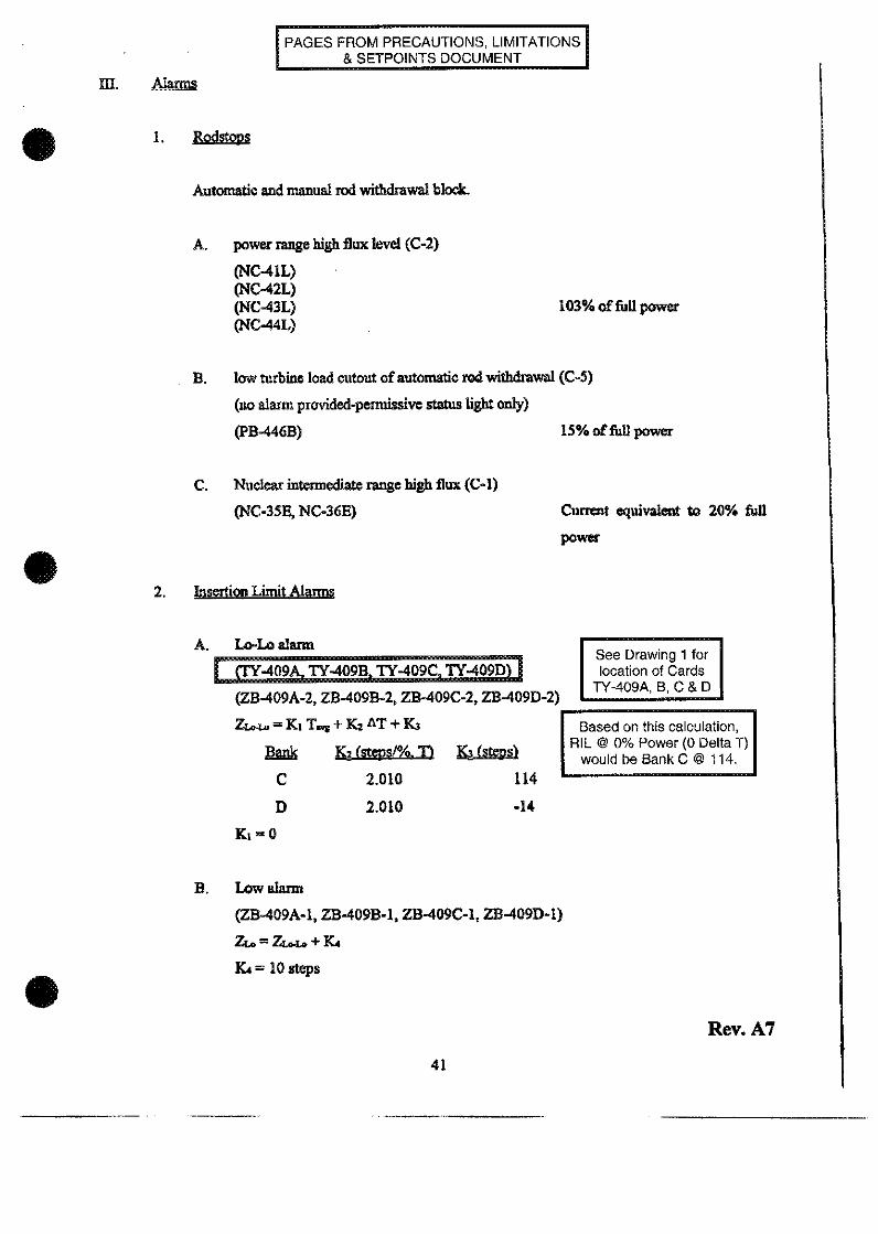
2. Insertion Limit Alarms
A. L-Loa alarm
40 Y409BI TY-409 T-49
(ZB-409A-2, ZB409B-2, ZB-409C-2, ZB409D-2)
Z =Ki T s+K 2 AT + K3
Bak K2tept/0. KTa1
C 2.010 114
D 2.010 -14
See Drawing 1 folocation of Cards
I Y-409A, B. C & D
I
Based on this calculationRIL @ 0% Power (0 Delta T)
would be Bank C @ 114.
Ki=0
B. Low alarm
(ZB-409A-1, ZB-409B-1, ZB-409C-1, ZB409D-1)
ZL. = ZLO. + K4
KL = 10 steps
Rev. A7
41

0
Control Bank Insertion UlmitsLow-Low Alarm Setponts
a.
Powe (/0);O
-J

QUESTIONS REPORTfor HLT-29 rebuttal Questions
05SEA2.03 001/1/,IBLACKOUT/CA 3.9/4.7/NEW/FAO 11005,IRO
Question 42.:
There is a Station Blackout in progress for Unit 1. The 2C DG is being started for Unit IIAW ECP-0.0, Loss Of All A.C. Power. Which one of the following statements iscorrect that will ensure 2C DG is running properly with service water supplied after thestart pushbutton is depressed?
A. * Check DJ06, Unit I 2C DG output breaker, automatically closes.* Close DG13, 1G 4160 V bus tie to 1J 4160 V bus.* Manually start two service water pumps on B Train.
B. * Close DJ06, Unit 1 2C DG output breaker, manually from the EPB.* Close DG13, IG 4160 V bus tie to IJ 4160 V bus.* Manually start two service water pumps on B Train.
Co * Check DJ606, Unit 1 2C DG output breaker, automatically closes.* The LOSP sequencer will automatically run.* All LOSP loads will automatically start.
D. * Close DJ06, Unit 1 2C DG output breaker, manually from the EPB.* The LOSP sequencer will automatically run.* All LOSP loads will automatically start.
A. Incorrect - DJO6 will auto close, however, DG13 will auto close and the SW pumpswill auto start since there is no SI.
B. Incorrect - DJO6 will auto close, and the LOSP sequencer will run and start all loads.
C. Correct - Check DJ06, Unit I 2C DG output breaker, automatically closes, theLOSP sequencer will automatically run, and all LOSP loads will start.The Unit I output breaker (DJ06-1) will close automatically when the 2C diesel is runningat rated voltage and freguency. and It was manually started from the EPS in mode I withthe USS In the Unit I position. Also, an undervoltage condition must exist on the iJ bus, andthe 13 diesel output breaker must be open.Load shed of bus loads must be completed prior to closing the output breaker for any dieselgenerator. When the output breaker for the 2C DG is closed, then the LOSP sequencer on4160V G should run if no SI Signal is present. This will load the 2C diesel fromt he Gsequencer. in which case the ooerator needs to carefully monitor the loading on the dieselsothat it WU not exceed the continuous load rating of the diesel (2850 iW). If a safety injectionsignal is present, then the operator is reminded that neither the LOSP or the SI sequencer willrun and the SI loads must be manually started.
D. Incorrect- DJO6 will auto close.
Tuesday, January 25, 2005 1:04:02 PM 4

QUESTIONS REPORTfor HLT-29 rebuttal Questions
055EA2.03 Station Blackout- Ability to determine and interpret the following as theyapply to a Station Blackout: actions necessary to restore power.
State the basis for all cautions, notes, and actions associated with ECP-0.O/0.1/02(OPS52532A03)Describe the sequence of major actions associated with ECP-0.0/0.1/02.(OPS52532A04)
POSITION:
In discussions with some of the individuals who picked 'A" as the correct response, it was determined thatan alternate way to analyze the question was to approach it in the procedural verification mode. Thismethod is reinforced by the wording of the stem with the following items:
* The DG was being started IAW ECP-0.0, Loss Of All AC Power.* Which one of the following statements is correct that will ensure 2C DG is running properly with
service water supplied after the start pushbutton is depressed?
These applicants took the question to mean procedurally how the operator would verify that the 2C DG isrunning properly with service water. These actions were fresh their minds since one exam simulatorscenario and an active JPM had them start the 2C DG in the SBO mode.
At FNP, the term VERIFY means to observe that an expected condition exists and take action to establishthe condition if it does not exist. Each step in the ECP-0.0 has the word Verify at the beginning of thesteps. The term ENSURE means to 'To make sure or certain'. We are asking the candidate to make sureor certain that the 2C DG is running properly with SW supplied IAW ECP-0.. Then the distracters havethe words check a breaker automatically closes or to close the breaker. If the candidate performed theactions as written in A and B, a success path is identified that is procedurally correct due to the termsENSURE and VERIFY.
In reviewing the steps of ECP-0.0, you can find the actions in answers "A" and "B" as high level actions tobe verified when starting 2C DG. The question uses the phrase "ensure 20 DG is running properly withservice water supplied". A candidate who interprets the question as asking for what procedurally isrequired could pick either answer "A" or "B" as correct based on these options actually listing componentsthat are required to be verified for the DG to be supplied with SW. Also, if viewed from this perspective,answer "C" would not be chosen based on it not listing the components detailed in the procedural steps.
Answer "C" was chosen as the correct response on the key because it is describes the system designedresponse to the 2C DG being started in the Station Backout (SBO) mode. Originally the question waswritten to ask with the conditions given what will be the required actions to make sure 2C DG is runningproperly with SW supplied. The answer as written is correct in that it defines what will happen when thestart pushbutton is depressed. The operator will, in effect, have to do nothing.
Answer "0 contains parts based on procedural knowledge and system knowledge. If the actions weretaken as in distracter B and the sequencer were to run as it will, then this would be a correct answer.
During the exam 2 candidates asked questions on this question as follows.42 1138 Wanted to know if SI had occurred due to the LOSP.
Dan Ans: Use the info in the question.David 1215 Does this affect Unit 2 also? U-2 power is needed to close DJO6.
B. Ans: Answer the question as written.
Tuesday, January 25, 2005 1:04:02 PM 5
QUESTIONS REPORTfor HLT-29 rebuttal Questions
intent and there was confusion among the candidates.
RECOMMENDATION:Due to the the wording in the stem, any distracter could be picked and ensure that asuccess path to get SW supplied to the DG. Each candidate read the stem in adifferent light and depending on that viewpoint, was correct.We submit based on these facts that all answers are correct and request this questionbe thrown out.
Hypothesis of why the exam team missed this on review.The exam team validated this exam and 2 of the 3 validators missed this question. Werewrote the question and reviewed the question and missed the wording issues.
Tuesday, January 25, 2005 1:04:02 PM 6

01/24/05 10:40:57 I..1, . ..
XAK:>.IS, . i....t-, . FNP-0-SOP-0.8
August 11, 2003Version 8.0
FARLEY NUCLEAR PLANT
SYSTEM OPERATING PROCEDURE
FNP-0-SOP-0.8SAFETY
EMERGENCY RESPONSE PROCEDUREUSER'S GUIDE
RELATE
PROCEDURE USAGE REQUIREMENTS PER FNP-0-AP-6 SECTIONSContinuous Use
Reference Use
Information Use ALL
Approved:
TODD YOUNGBLOODOperations Manager
Date Issued 8-12-03

>&y" .Y. An * ;K ~ Si
01/24/05 10:41:18 > FNP-0-SOP-0.8ATTACHMENT1
GLOSSARY OF TERMS AND ACTIONS VERBS
Check To note a parameter or condition and compare it with a specifiedrequirement. No action to change the parameter or condition isimplied.
Example: Check reactor tripped
Close To change the physical position of a device. Closing a valveprevents fluid flow. Closing a breaker allows current flow.
Example: Close MSIVs for affected steam generators.
Compare To examine two or more parameters to determine the similarities ordifferences among them.
Example: Compare local valve position with control roomindication.
Complete To perform a specified action or task to a final end.
Example: Complete RCS cooldown to required core exittemperatures.
Consult To confer with or seek expert advice.
Example: Consult TSC staff to determine long term plant status.
Continue To maintain a course of action or to resume a course of action whichhas been interrupted. This implies a continuing action.
Example: Continue efforts to restore off site power.
Control To operate equipment to satisfy procedure requirements on processparameters. This implies a continuing action.
Example: Control charging and letdown to stabilize pressurizerpressure.
Decrease DO NOT USE
Deenergize To remove electric power from.
Example: Deenergize the accumulator discharge valves.
Page 2 of 8 Version 8.0

01/24/05 10:41:31 t,/ g x , FNP-O-SOP-0.8ATTACHMENT 1
GLOSSARY OF TERMS AND ACTIONS VERBS
Trend Do not use.
Trip To manually actuate a semi-automatic feature. Generally directsmanual action which causes a component to cease operation in a
short time frame.
Example: Trip the heater drain pumps.
Turn off To remove power from.
Example: Turn off pressurizer heaters.
Turn on To supply power to.
Example: Turn on pressurizer heaters.
Unlock To unfasten a restricting device so that a component may beoperated.
Example: Unlock and close one isolation valve for any failedatmospheric relief
Using Directs operator to employ another procedure or portion of aprocedure for guidance to perform a task. The referenced procedure
does not become the controlling document
Example: Align 2C air compressor to Unit 1 usingFNP-I -SOP-3 1.0, COMPRESSED AIR SYSTEM.
Vent To permit a fluid under pressure to escape.
Example: Vent the charging pump seals.
Verify To observe that an expected condition exists and take action toestablish the condition if it does not exist.
Example: Verify all available AFW pumps running.
Page 8 of 8 Version 8.0

1/21/2005 13:23 iJ just >
FNP-1-ECP 0.0 LOSS OF ALL AC POWER Revision 20
Step Action/Expected Response Response NOT Obtained
tt.****t***************************** *** ** ** ***tt
CAUTION: A running diesel generator will overheat if adequate SW flow is notprovided within 3 minutes. Steps 5.3 through 5.7 must be performedimmediately to verify adequate SW flow once a diesel generator hasbeen started.
.................. ******* ******** ***************t...t.t ...*....************...
NOTE: Load shed of bus loads must be completed prior to closing the outputbreaker for any diesel generator.
5.2 Check I 2A. IC or 1B diesel 5.2 Perform 2C DG SBO start asgenerator running for Unit 1. follows.
* Check DIESEL SPEED 5.2.1 Verify 2C DG MODE SELECTORindication GREATER THAN switch in MODE 1.0 rpm.
5.2.2 Place 2C DG UNIT SELECTORQR switch in UNIT 1.
* Check FREQUENCY METER 5.2.3 WHEN load shed verified.indication - GREATER THAN THEN depress 2C DG DIESEL58 llz. START pushbutton.
_QR 5.2.4 Verify 2C DG starts.
* Check DIESEL AT SYN SPEEDlight LIT.
NOTE: The LOSP sequencer should run when output breaker closes, if no SIsignal is present. If an SI signal is present, neither sequencerwill run and SI loads must be started manually.
5.2.5 Verify Unit I 2C DG outputbreaker DJ06 closes.
5.2.6 Verify breaker DG13 closed.(1G 4160 V bus tie to IJ4160 V BUS)
Step 5 continued on next page.
Page Completed
Page 7 of 37

1/21/2005 13:23 4 1 TFNP-1-ECP-0.O LOSS OF ALL AC POWER Revision 20
Step Action/Expected Response Response NOT Obtained
5.2.7 Verify breaker DG02 closed.(IG 4160 V bus tie to IL4160 V bus)
5.2.8 IF 1G 4160V bus energized.TH-N proceed to step 5.7.
NOTE: * Starting 1-2A or 1B diesel generator should be attempted first.
* Any attempted start of a diesel generator which has automaticallytripped should be performed locally in Mode 4.
5.2.9 _WN1 load shed verified,THEN start any dieselgenerator.
5.2.9.1 Start diesel generatorfrom EPB in Mode 2 usingSTART pushbutton.
OR
5.2.9.2 Direct diesel operatorto start dieselgenerator in MODE 4using FNP O SOP-38.1,EMERGENCY STARTING OF AD1ESEL GENERATOR.
OR
5.2.9.3 Direct diesel operatorto perform a manualemergency start of 1-2Aor 1B diesel generatorusing FNP-0-SOP-38.1.EMERGENCY STARTING OF ADIESEL GENERATOR.
OR
5.2.9.4 IF attempts to start adiesel generator fail,THEN proceed tostep 5.9.
Step 5 continued on next page.
_ Page Completed
Page 8 of 37

1/21/2005 13:23 , '. , -:T9f': i It
FNP-L-EP-O.OI LOSS OF ALL AC POWER Revision 20
Step
m-Action/Expected Response Response NOT Obtained
I I
5.7 Verify adequate SW flow.
5.7.1 Verify two SW PUMPS inenergized train - RUNNING.
[] A Train (IA, lB or IC)[] B Train (ID, IE or iC)
5.7.2 IF A train energized,THEN verify SW TO/FROM DGBLDG - A HDR QIP16V519/531open.
5.1.3 IF B train energized,THEN verify SW TO/FROM DGBLDG - B HDR QIPF6V5S18/536open.
Step 5 continued on next page.
| _Page Completed
Page 14 of 37

subsequent steps. Each time a step energizes, a white lamp lights to indicate sequencer progress.
A green lamp (LOSP MANUAL LOAD START) lights at the completion of the sixth step if all
steps were energized. This lamp provides indication that all six steps received the proper signal
and that additional loads may be started safely. A red lamp (LOSP INCOMPLETE
SEQUENCE) lights at the completion of the sixth step if all steps did not energize, indicating
that a malfunction has occurred. The lamps lock in and must be reset by depressing the lamp
reset push button located beneath each light display.
At the completion of the sixth step, the sequencer signal feeds back to block the
sequencer run signal. Blocking the run signal removes the close signal from the breakers on each
step and returns the sequencer to a standby condition. This allows manual operation of all LOSP
loads.
During an LOSP, bus IJ will normally be supplied emergency power from diesel
generator IB. With diesel generator IB breaker (DG08-1) closed, the diesel generator 2C output
breaker (DJ06-1) will be blocked from closing.
D COutt B Logic
Because the 2C diesel is the SBO diesel, its output breaker (Figure 20) controls are
different from the emergency diesel breaker controls.
The Unit I output breaker (DJ06- 1) will close automatically when the 2C diesel is running
at rated voltage and frequency, and it was manually started from the EPB in mode I with the
USS in the Unit I position. Also, an undervoltage condition must exist on the 1J bus, and the lB
diesel output breaker must be open.
The Unit 11 output breaker (DJ06-2) operates the same as the Unit I output breaker. To
manually close DJ06-1 from the EPB, 2C diesel must be operating in mode 2. To start the diesel
in mode 2, the USS must be in the TEST position.
BI J and B2J Scuencer Logic
Normally, an UV condition on 4160V bus IJ or 2J will generate a load shed signal. The
load shed signal for the B I J sequencer will trip river water pumps 4 and 5. The load shed signal
18 OPS-52103F - 40102D- ESP-52103F
immediately may result in restart of the diesel generator when the low speed relay de-energizes. If
the diesel generator is supplying power to the emergency bus and does not have SW cooling being
supplied to it, then the diesel generator must be rapidly shutdown. This rapid shutdown should

prevent diesel engine failure, if the shutdown occurs within 3 minutes of diesel engine being started.
The immediacy of these steps is to prevent a subsequent restart of the diesel generator after the DG
Stop pushbutton has been depressed.
The LOSP sequencer may run when the output breaker is closed. The LOSP sequencer
should anm when output breaker closes, if no SI signal is present. If a SI signal is present, neither
sequencer will aun and SI loads must be started manually.
Caution. If both Unit I and Unit 2 B Train 4160V busses become de-energized, then
make one attempt per unit to restore power to at least one unit's B Train 4160V bus by starting
the designated B Train DG. If power cannot be restored using either IB or 21B Drs, then
immediately align and start the SBO DO to provide power to one unit's B Train 4160V bus.
Caution. When energizing any dead bus from a startup transformer, the SYNCH BYPASS
switch must be held in the BYPASS position when closing the associated startup transformer output
breaker. Closing the alternate output breaker from a startup transformer may cause safety related
AC power to be cross-connected.
Recovery Actions
At this point in the procedure, all attempts to restore AC power to an emergency bus from
any source (DOs or off-site) have failed. With no AC power available to any emergency bus, plant
conditions will begin to deteriorate due to RCP seal leakage. Actions should now be initiated to
minimize the deterioration of the plant conditions. Actions will be taken to prevent auto start of
emergency loads, reduce DC loads, and isolate the RCP seals. Because of the changes made to
various equipment and system lineups that are going to be completed in subsequent steps, the
operator must proceed to an appropriate recovery procedure whenever AC power is restored.
When the point of the procedure has been reached when power to any bus cannot be
restored, the step will direct the operator to proceed in the procedure to verify SW flow and a
flowpath to the DGs available when power is restored to any emergency bus. The procedure will
then direct the operator to perform the necessary actions to restore plant equipment to a "normal"
configuration needed for recovery following a loss of all AC power.
Whenever a SI signal is present, the operator is directed to reset the SI signal so that SI
equipment (i.e., pumps and valves) will not automatically actuate upon AC power restoration. This
will permit manual loading of equipment as directed following restoration of power to the
I I _ r (/E

If no emergency bus can be loaded on any DG for whatever reason (no excitation, breaker
won't close, etc.), then the RNO column will direct the operator to attempt to load an emergency bus
from an off-site power supply while continuing efforts to start one diesel generator.
If an emergency bus (41 60V bus F or G) has been restored with electrical power from a DG,
then the power supply should be sufficiently stable to accept automatic sequencing of loss of off-site
power (LOSP) or SI loads on the emergency bus without detrimental effects. In this case. the
operator will verify Scice Water (SW) pumps are running with adequate SW flow to DGs being
delivered and then will be directed to procedure and step in effect (EEP-0 in all likelihood).
A caution applies any time a diesel is started to help to ensure the running diesel is provided
immediately with service water (SW) for cooling to protect it from overheating. If the DG cannot
be provided with sufficient cooling water, then it should be secured until SW is available to be
provided to the running DG.
Load shed of bus loads must be completed prior to closing the output breaker for any diesel
generator. When the output breaker for the 2C DG is closed, then the LOSP sequencer on 4160V
G should run if no SI Signal is present. This will load the 2C diesel from the G sequencer, in which
case the operator needs to carefully monitor the loading on the diesel so that it will not exceed the
continuous load rating of the diesel (2850 kW). If a safety injection signal is present, then the
operator is reminded that neither the LOSP or the SI sequencer will run and the SI loads must be
manually started.
Because of the increased capacity that is available from the big diesels (4075 kW versus
2850 kW), the operator should attempt to start one of them first. Also, the big diesels can be
emergency started by one of two methods locally per SOP-3 8. 1.
Any attempted start of a diesel generator that has automatically tripped should be perfonned
locally in Mode 4. This note reminds the operator that if the local mode selector switch (located
on the diesel local control panel) is placed in MODE 4 position, then the diesel cannot be
controlled from the EPB. To return control to the operator in the control room, then the local
control switch must be placed in the OFF position.
Failure to perform steps to shutdown a DG that is running without adequate SW
immediately may result in restart of the diesel generator when the low speed relay dce-energizes. If
the diesel generator is supplying power to the emergency bus and does not have SW cooling being
supplied to it, then the diesel generator must be rapidly shutdown. This rapid shutdown should
;__ 24j
QUESTIONS REPORTfor HLT-29 rebuttal Questions
071 K5.04 001/2/2/WASTE GAS/MEM 2.5/3. 1UNEW/FA0I 1005/RO/
Question 54: 1
The Shift Chemist has determined that oxygen concentration levels are 3.5% in the
Waste Gas System. Which one of the following is required to be accomplished lAW
SOP-51.0, Waste Gas System, to prevent an unsafe condition?
A. Dilute with nitrogen and transfer the smaller WGDT to #7 or #8 WGDT for further
sampling.
B& Dilute with nitrogen and vent the WGDT to the plant vent stack per SOP-51.1,
Waste Gas System Gas Decay Tank Release.
C. Place the waste gas compressor in service and dilute by combining the WGDT with
another WGDT that has a lower oxygen concentration.
D. Transfer the smaller WGDT to #7 or #8 WGDT and vent the WGDT to the plant
vent stack per SOP-51.1, Waste Gas System Gas Decay Tank Release.
Tuesday, January 25, 2005 1:04:02 PM 7
QUESTIONS REPORTfor HLT-29 rebuttal Questions
Due to the question for KA 004K5.49 on this exam, this question was asked in the
oxygen realm to prevent giving the answer or tips for that question. The words
flammable and explosive mixture were avoided as well and the word hydrogen was
avoided to keep from drawing the 2 questions together. The candidate will have to
either take the unsafe condition at face value or know what the unsafe condition is.
The operational implications of too high an oxygen level is to dilute and get rid of the
WGDT contents to prevent a flammable mixture.
A. Incorrect - Diluting with nitrogen is correct but then the correct action is to get rid ofit, not store it for future problems.
B. Correct - Dilute with nitrogen and vent the WGDT to the plant vent stack per
SOP-51.1, Waste Gas System Gas Decay Tank Release.This will bring the flammable concentration down and the get it out of the tank to
prevent a future high 02 concentration. This is done to prevent a flammable mixture of02 to H2 IAW SOP-51.
C. Incorrect - This is not a correct action but the candidate may believe this would
dilute it and allow for a safer environment.
D. Incorrect - There is no need to transfer this from a smaller tank to the larger holdingtanks for future disposal.
Reference:CFR: 41.5 /45.7TR 13.12.3. Waste Gas Monitoring Lesson PlanThis technical requirement states that the concentration of oxygen in any portion of thegaseous radwaste treatment system shall be limited to < or eaual to 2% by volume whenever thehydrogen concentration in that pion of the gaseous radwaste treatment system exceeds 4% by volumeand the hydrogen and oxygen monitors required b TR 13.12.1 are operable. If the hydrogen and oxygenmonitors required by TR 13.12.1 are operable and the concentration of oxygen in the gaseous radwastetreatment system >2% by volume but < or equal to 4% by volume, then reduce oxygen concentration towithin limits within 48 hours.
SOP-51.0 P&L3.11 Gas decay tanks with 02 levels greater than the required limits should be diluted
with N2 and purged to the plant vent in accordance with FNP- I -SOP-5 1.1,
WASTE GAS SYSTEM GAS DECAY TANK RELEASE. until 02 level is within
limits.
071 K5.04 Waste Gas Disposal - Knowledge of the operational implication of the
following concepts as they apply to the Waste Gas Disposal System.Relationship of hydrogen/oxygen concentrations to flammability.
Identify any special considerations such as safety hazards and plant condition changes
that apply to the Waste Gas System (OPS521 06B04).
Tuesday, January 25, 2005 1:04:02 PM 8

QUESTIONS REPORTfor HLT-29 rebuttal Questions
POSITION:
The stem used the wording of "unsafe condition" as the driving force behind taking some action.
Reviewing our procedures, 3.5% by itself does not constitute an unsafe condition.
Based on the TRM, section 13.12.3, this oxygen concentration would only be out of spec if hydrogen
exceeded 4%. Since the hydrogen concentration is not given, one can assume that the TRM conditions
are satisfied.
Chemistry typically provides recommendations as to the disposition of the contents of a WGDT based on
H2 concentration, 02 concentration and curie content exceeding limits. Operations may also decide to
make releases for operational concerns such as pressure, planned maintenance activities or planned
future needs.
Since none of these items were apparent in the stem of the question, the candidates were left to draw
their own conclusions and select a success path based on that conclusion.
The following procedural guidance exists on the disposition of waste gas in a WGDT:
A review of FNP-1/2-CCP-2 03.0, CHEMISTRY AND ENVIRONMENTAL GROUP CONSIDERATIONS
DURING OPERATIONAL TRANSIENTS Section 5.18, does not provide for a mandatory release of a
WGDT with the conditions given in the question. If hydrogen exceeds 4% and oxygen exceeds 1% then
CCP-203 would mandate a release after dilution with nitrogen to below the TRM limit. The only statement
in CCP-203 suggesting a release is contained in the subsection (Page 46, section E) describing the
addition of nitrogen. It is worded as follows: "Generally, after the addition of nitrogen, it will be desired to
release the contents of the WGDT." In practice the other factors of curie content, final tank pressure and
final oxygen/hydrogen sample results may result in a decision to hold the tank for future use. This option
is allowed by CCP-203.
STP-424, OXYGEN AND HYDROGEN DETERMINATION FOR THE WASTE GAS SYSTEM, provides
instructions and actions to be taken on out of spec conditions for a Waste Gas Sample. For the given
sample results, no actions are required.
SOP-51.0 gives the instructions for alignment of the waste gas system in various modes, Section 4.13
(Nitrogen Addition To Waste Gas System), Section 4.10 (Transferring Gas Between Gas Decay Tanks) or
section 4.19 (Transferring Gas Between Gas Decay Tanks With The System Shutdown)
The question also asks the REQUIRED actions. Since no hydrogen limit is exceeded; no action is
required for the stated conditions.
Answer A describes a valid alternative based on the following reasons:
1. The Oxygen concentration is out of spec for oxygen but the hydrogen concentration is not given.
TRM 13.12.3 does not mandate a gas release as a required action for an out of spec oxygen
concentration only. This is the only distracter that mentions the word sampling and implies past sampling
has occurred because further sampling will be done.
2. Typically Operations will follow Chemistry recommendations as to the disposition of gas in out of
spec tanks. Several factors are taken into consideration before making this type of recommendation
including hydrogen and oxygen content in other tank (if a transfer is desired), curie content (if a release is
desired), initial / final tank pressure (if dilution with nitrogen is desired) and other operational concerns.
Answer B is an option for the disposition of the contents of this tank although this would not be required by
plant procedure.
Answer C describes a viable option for the disposition of a WGDT with high oxygen concentration. Since
no limits are exceeded, a transfer to another WGDT and subsequent release is allowed.
Answer D could also describe a viable option for the disposition of a WGDT with high oxygen
Tuesday, January 25, 2005 1:04:02 PM

QUESTIONS REPORTfor HLT-29 rebuttal Questions
concentration. Since no limits are exceeded, a transfer to another WGDT and subsequent release is
allowed.
RECOMMENDATIONS:We contend that all responses could be selected as a correct answer based on the
information given in the stem and the question be thrown out.
Hypothesis of why the exam team missed this on review.This question was rewritten a number of times. One factor that came in to play was
another question on this exam; KA 004K5.49.This question was asked in the oxygen realm to prevent giving the answer or tips for
that question. We did not put in 4% for hydrogen due to the possibililty of giving
information to the candidate for that question.
004K5.49 Chemical and Volume ControlK5 Knowledge of the operational implications of the following concepts as they apply to
the CVCS: K5.49 - Purpose and method of hydrogen removal from the RCS before
opening system: explosion hazard, nitrogen purge
The words flammable and explosive mixture were avoided as well and the word
hydrogen was avoided to keep from drawing the 2 questions together.
We made this an oxygen question but missed the mark by not giving any hydrogen
concentrations. This would have been a good question to reassign the KA value, but
we had already reassigned one KA dealing with liquid / gas waste issues.
Tuesday, January 25, 2005 1:04:02 PM 10

Waste Gas MonitoringTR 13.12.3
13.12 Explosive Gas and Storage Tank Radioactivity Monitoring (EGSTRAM) Program
TR 13.12.3
TR 13.12.3
Waste Gas Monitoring
The concentration of oxygen in any portion of the gaseous radwaste treatmentsystem shall be limited to:
A. < 2% by volume whenever the hydrogen concentration in that portion of thegaseous radwaste treatment system exceeds 4% by volume and thehydrogen and oxygen monitors required by TR 13.12.1 are OPERABLE; or
B. < 1 % by volume whenever the hydrogen concentration in that portion of thegaseous radwaste treatment system exceeds 4% by volume and thehydrogen and oxygen monitors required by TR 13.12.1 are not OPERABLE.
APPLICABILITY: At all times.
ACTIONS----------------------------------------------------------- NOTE----------------------------------------------------------
TR 13.0.3 and TR 13.0.4 are not applicable.
CONDITION REQUIRED ACTION COMPLETION TIME
A. Monitors in TR 13.12.1OPERABLE
AND
Concentration of oxygenin the gaseous radwastetreatment system > 2% byvolume but •4% byvolume.
A.1 Reduce oxygenconcentration to • 2% byvolume.
48 hours
Farley Units 1 and 2Technical Requirements
13.12.3- 1 Version 8.0
4-
Waste Gas MonitoringTR 13.12.3
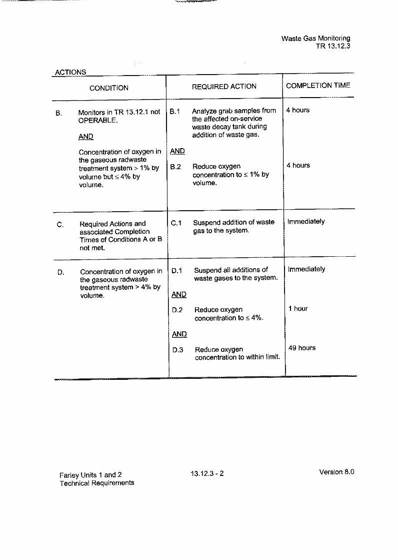
ACTIONS
CONDITION REQUIRED ACTION COMPLETION TIME
B. Monitors in TR 13.12.1 not B.1 Analyze grab samples from 4 hoursOPERABLE. the affected on-service
waste decay tank duringAND addition of waste gas.
Concentration of oxygen in ANDthe gaseous radwastetreatment system > 1% by B.2 Reduce oxygen 4 hours
volume but < 4% by concentration to < 1% byvolume. volume.
C. Required Actions and C.1 Suspend addition of waste Immediatelyassociated Completion gas to the system.Times of Conditions A or Bnot met.
D. Concentration of oxygen in D.1 Suspend all additions of Immediatelythe gaseous radwaste waste gases to the system.treatment system > 4% byvolume. ANQ
D.2 Reduce oxygen 1 hourconcentration to < 4%.
AND
D.3 Reduce oxygen 49 hoursconcentration to within limit.
Farley Units 1 and 2Technical Requirements
13.12.3 - 2 Version 8.0

Waste Gas MonitoringTR 13.12.3
T-rflUKIEHAI PrfQi IIPFNMPU T SI IRVFII LANCESI_~ 1 I- m_ =. __-.- --
SURVEILLANCE FREQUENCY
TRS 13.12.3.1 Verify concentration of hydrogen or oxygen in thegaseous radwaste treatment system to be less thanthe limit by monitoring the waste gases in the gaseousradwaste treatment system.
During addition ofwaste gases to thegaseous radwastetreatment system:
by use of thehydrogen and/oroxygen monitorsrequired by TR13.12.1, whenOPERABLE
OR
by analyzing grabsamples from theaffected wastedecay tank at leastonce every 4 hours.
A
Farley Units 1 and 2Technical Requirements
13.12.3 -3 Version 8.0

EGSTRAM ProgramB 13.12
B 13.12 EXPLOSiVE GAS AND STORAGE TANK RADIOACTIVITYMONITORING (EGSTRAM) PROGRAM
BASES
TR 13.12.1 Waste Gas Monitoring Instrumentation
This instrumentation monitors (and controls) the concentrations of potentially explosive gas
mixtures in the waste gas holdup system. The OPERABILITY and use of this instrumentation
are consistent with the requirements of General Design Criteria 60 and 63 of Appendix A to 10
CFR Part 50.
TR 13.12.2 Liquid Holdup Tanks
Restricting the quantity of radioactive material contained in the specified tanks provides
assurance that in the event of an uncontrolled release of the tanks' contents, the resulting
concentrations would be less than the limits of 10 CFR Part 20, Appendix B, (to paragraphs
20.1001 -20.2401), Table 2, Column 2, at the nearest potable water supply and the nearest
surface water supply in an unrestricted area.
TR 13.12.3 Waste Gas Monitoring
This Technical Requirement is provided to ensure that the concentration of potentially explosive
gas mixtures contained in the waste gas holdup system is maintained below the flammability
limits of hydrogen and oxygen. During recombiner operation, an automatic control feature is
included in the system to prevent the oxygen concentration from reaching these flammability
limits. The automatic control feature includes isolation of the source of oxygen (the recombiner
oxygen supply), to reduce the concentration below the flammability limit. When the recombiner
is not operating and thus the recombiner oxygen supply is isolated, a grab sample can be taken
to measure oxygen levels in the waste gas system. Maintaining the concentration of oxygen
below the flammability limit when hydrogen is above 4% by volume provides assurance that the
releases of radioactive materials will be controlled in conformance with the requirements of
General Design Criterion 60 of Appendix A to 10 CFR Part 50.
TR 13.12.4 Gas Storage Tanks
Restricting the quantity of radioactivity contained in each gas storage tank provides assurance
that in the event of an uncontrolled release of the tanks' contents, the resulting total body
exposure to an individual at the nearest exclusion area boundary will not exceed 0.5 rem. This
is consistent with Standard Review Plan 15.7.1, 'Waste Gas System Failure".
Farley Units 1 and 2 B 13.12-1 Version 3.0
Technical Requirements Bases

I I z
I I I.
I E � :I, -, , 1�
01/21/05 12:27:57 FNP-1 -STP-424January 27, 2003Version 15.0
FARLEY NUCLEAR PLANT
SURVEILLANCE TEST PROCEDURE
FNP-1 -STP-424
OXYGEN AND HYDROGEN DETERMINATION FOR THEWASTE GAS SYSTEM
SAFETY
RELATED
f PROCEDURE USAGE REQUIREMENTS PER FNP0-AP-6 SECTIONS
Continuous Use
Reference Use ALL
Information Use.. .. =
Approved:
C.L. BuckTechnical Manager
Date Issued 01/29/03

01/21/05 12:27:57 +. K FNP-1-STP-424
OXYGEN AND HYDROGEN DETERMINATION FOR THEWASTE GAS SYSTEM
1.0 Purpose
This provides a means of determining the oxygen in the Waste Gas Inlet and WasteGas Decay Tank.
2.0 Scone
2.1 This surveillance (Ref. 7.1) is required in all modes when adding waste gases to
the waste gas system during the following conditions:
2.1.1 No recombiner oxygen analyzers are operable and addition of waste
gas to the waste gas system is to continue TR 13.12.1, actions A andB.
2.1.2 No recombiner hydrogen analyzers are operable and addition of waste
gas to the waste gas system is to continue TR 13.12.1, action C.
2.2 This surveillance (Ref. 7.2) is required in all modes, at all times, any time a waste
gas decay tank is sampled for oxygen/hydrogen concentration whether thesample is routine scheduled sample, or a special sample requested for any
reason. This surveillance applies on any waste gas decay tank, inservice OR instandby.
2.3 This procedure is not subject to the guidance in FNP-0-AP-52 pertaining to therelease of repetitive tasks.
3.0 Acceptance Criteria
3.1 During recombiner operation, with less than the minimum number of oxygen
monitors operable, the analysis for oxygen (02) in the affected on-service waste
gas decay tank during the addition of waste gas shall verify oxygen in
concentrations < 1 percent by volume once per 4 hours; otherwise, stop theaddition of gas to the waste gas system.
At all times, with hydrogen and oxygen monitors required by TR 13.12.1OPERABLE, the concentration of oxygen in any portion of the gaseous radwaste
treatment system shall be limited to < 2% by volume whenever the hydrogenconcentration in that portion of the gaseous radwaste treatment system exceeds4% by volume.
3.3 At all times, with hydrogen and oxygen monitors required by TR 13.12.1 NOTOPERABLE, the concentration of oxygen in any portion of the gaseous radwastetreatment system shall be limited to s 1% by volume whenever the hydrogen
concentration in that portion of gaseous radwaste treatment system exceeds 4%
by volume. Verification shall be accomplished once per 4 hours; otherwise stopaddition of gas to the waste gas system.
-1 - Version 15.0
01/21/05 12:27:57 FNP-1 -STP-424
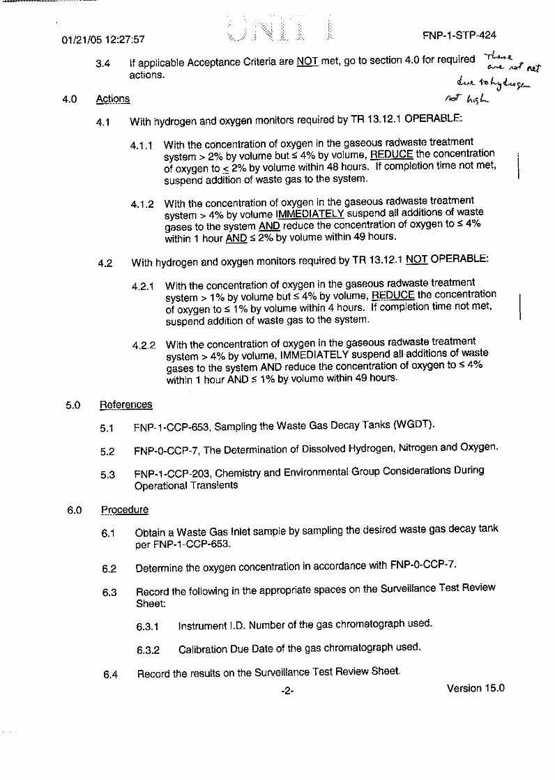
3.4 If applicable Acceptance Criteria are NOT met, go to section 4.0 for required
actions. &tt
4.0 Actions e-.L
4.1 With hydrogen and oxygen monitors required by TR 13.12.1 OPERABLE:
4.1.1 With the concentration of oxygen in the gaseous radwaste treatmentsystem > 2% by volume but s 4% by volume, REDUCE the concentrationof oxygen to < 2% by volume within 48 hours. If completion time not met,suspend addition of waste gas to the system.
4.1.2 With the concentration of oxygen in the gaseous radwaste treatmentsystem > 4% by volume IMMEDIATELY suspend all additions of wastegases to the system AND reduce the concentration of oxygen to s 4%within 1 hour AND S 2% by volume within 49 hours.
4.2 With hydrogen and oxygen monitors required by TR 13.12.1 NOT OPERABLE:
4.2.1 With the concentration of oxygen in the gaseous radwaste treatmentsystem > 1% by volume but S 4% by volume, REDUCE the concentrationof oxygen to S 1% by volume within 4 hours. If completion time not met,suspend addition of waste gas to the system.
4.2.2 With the concentration of oxygen in the gaseous radwaste treatmentsystem > 4% by volume, IMMEDIATELY suspend all additions of wastegases to the system AND reduce the concentration of oxygen to 5 4%within 1 hour AND s 1% by volume within 49 hours.
5.0 References
5.1 FNP-1-CCP-653, Sampling the Waste Gas Decay Tanks (WGDT).
5.2 FNP-0-CCP-7, The Determination of Dissolved Hydrogen, Nitrogen and Oxygen.
5.3 FNP-1 -CCP-203, Chemistry and Environmental Group Considerations DuringOperational Transients
6.0 Procedure
6.1 Obtain a Waste Gas Inlet sample by sampling the desired waste gas decay tank
per FNP-1-CCP-653.
6.2 Determine the oxygen concentration in accordance with FNP-0-CCP-7.
6.3 Record the following in the appropriate spaces on the Surveillance Test ReviewSheet:
6.3.1 Instrument 1.D. Number of the gas chromatograph used.
6.3.2 Calibration Due Date of the gas chromatograph used.
6.4 Record the results on the Surveillance Test Review Sheet.
-2- Version 1 5.Q

01/21/05 12:27:57 < FNP-1-STP-424
6.5 Record whether the Waste Gas Tank was Inservice (i.e. Gas being added to
tank) or not in service (i.e., Tank being sampled for reason other than Gasaddition to tank).
6.6 Indicate on the STRS which Acceptance Criteria is (are) applicable for this
sample by checking appropriate box(es). Refer to FNP-1 -CCP-203.
6.7 Notate in the "Comments" on the STRS area above "Performed by' why the tank
was sampled and any actions taken due to the results (for example, 'Tanksampled due to VCT burp. Operations requested to remove tank from serviceand not to add gas to this tank due to Oxygen level").
6.8 Document the date/time "Performed by" as the time 6.4 is performed.
7.0 Technical Specification Reference and Technical Requirements Manual Reference
7.1 5.5.12, TR 13.12.1
7.2 5.0, TR 13.12.3
-3- Version 15.0

jj.,. >: l .
L n t 2 ; : A01/21/05 1 2:27:57 FNP-1 -STP-424
FARLEY NUCLEAR PLANTSURVEILLANCE TEST REVIEW SHEET
SURVEILLANCE TEST NUMBERFNP-1 -STP-424
TECHNICAL SPECIFICATIONSREFERENCEand TECHNICAL REQUIREMENTSMANUAL REFERENCE5.5.12. 5.0. TR 13.12.1, TR 13.12.3
TITLE: Oxygen and Hydrogen Determination for the Waste Gas SystemMODE (S) REQUIRING TEST: All modes (1) Recombiners inservice refer to TR 13.12.1 or(21 No recombiners inservice refer to TR 13.12.3B.
TEST RESULTS REFERENCES
WGDT #: Rev. Int.Result: % Oxygen 1. FNP-1-CCP-653
% Hydrogen 2. FNP-0-CCP-7
[]Satisfactory [] Unsatisfactory Instrument o. No.
Deficiencies: Calibration Due Date aWGDT STATUS: [ In Service (Gas being
____ ___ ____ ___ ____ ___ ____ ___ ____ ___ ___ added)[ Not In Service
Comments: ___________ ___ ACCEPTANCE CRITERIAo [ During recombiner operation with less than the
minimum number of oxygen monitors operable, grabsamples from affected on-service waste decay tankduring addition of waste gas will be analyzed ANDoxygen content will be verified as < 1% every 4
Corrective Action: hours. (Procedure section 3.1)
At ail times, with hydrogen and oxygen monitorsrequired by TR 13.12.1 OPERABLE, the
____ ___ ____ ___ ___ ____ ___ ____ ___ ___ ____ ___ ___ concentration of oxygen in any portion of thegaseous radwaste treatment system shall be limitedto • 2% by volume whenever the hydrogenconcentration in that portion of the gaseous
Perf ormmed by: radwaste treatment system exceeds 4% by volume.(Procedure section 3.2)
Date/Time: /At all times, with hydrogen and oxygen monitorsrequired by TR 13.12.1 NOT OPERABLE.TR 13.12.38 requires the concentration of oxygen inany portion of the gaseous radwaste treatmentsystem shall be limited to < 1% by volume wheneverthe hydrogen concentration in that portion of thegaseous radwaste treatment system exceeds 4% byvolume. Verification shall be accomplished once per4 hours; otherwise stop addition of gas to the wastegas system. (Procedure section 3.3)
REVIEW - LEVEL II (or above)
Reviewed by: Date:
[ ] Procedure properly completed and satisfactory
[ I Comments:
FINAL REVIEW - LEVELII (or above)
Reviewed by: Date:
[ I Procedure properly completed and satisfactory
I I Comments:
Page 1 of I Version 15.0

TRM SPECIFICATIONS
TR 13.12 lTaste (as Monitoring lnstrUmentat
This technical requirement requires that one hydrogen monitor and two oxygen monitors
per recombiner are required during recombiner operations.
With one oxygen monitor for one or more recombiners inoperable immediately isolate the
oxygen supply to the affected recombiner(s). If both oxygen monitors for one or more
recombiners are inoperable then analyze grab samples from the affected on-service waste decay
tank during addition of waste gas and verify oxygen concentration remains less than I percent
within 4 hours. If the required hydrogen monitor for one or more recombiners is inoperable then
analyze grab samples from the affected on-service waste decay tank during addition of waste gas
and verify oxygen concentration remains less than I percent within 4 hours. If the above actions
are not meet immediately suspend addition of waste gas to the system. A report must be
prepared and submitted to the Commission if any oxygen or hydrogen monitor(s) for one or more
recombiners is inoperable for more than 30 days.
During recombiner operation a channel check will be performed every 24 hours and
Channel Operability Test (COT) will be perfonned every 31 days. A channel calibration shall be
performed every 92 days.
TR I 2k.3Waste Gas Monitonng
This technical requirement states that the concentration of oxygen in any portion of the
gaseous radwaste treatment system shall be limited to S2% by volume whenever the hydrogen
concentration in that portion of the gaseous radwaste treatment system exceeds 4% by volume
and the hydrogen and oxygen monitors required by TR 13.12.1 are operable. If the hydrogen and
oxygen monitors required by TR 13.12.1 are operable and the concentration of oxygen in the
gaseous radwaste treatment system >2% by volume but '4% by volume, then reduce oxygen
concentration to within limits within 48 hours.
The concentration of oxygen in any portion of the gaseous radwaste treatment system
shall be limited to •1 % by volume whenever the hydrogen concentration in that portion of the
gaseous radwaste treatment system exceeds 4% by volume and the hydrogen and oxygen
monitors required by TR 13.12.1 are NOT operable. If the hydrogen and oxygen monitors
15 OPS-52106B / 40303B15OS5216 /433

required by TR 13.12.1 are NOT operable and the concentration of oxygen in the gaseous
radwaste treatment system >1% by volume but <4% by volume, then analyze grab samples from
the affected on-service waste gas decay tank during addition of waste gas within 4 hours and
reduce oxygen concentration to within limits within 4 hours.
If the concentration of oxygen in the gaseous radwaste treatment system >4% by volume
then immediately suspend all additions of waste gas to the system, within one hour reduce
oxygen concentration to '4%, and within 49 hours reduce oxygen concentration to within the
limits specified above.
During the addition of waste gases to the gaseous radwaste treatment system, verify
concentration of hydrogen or oxygen in the gaseous radwaste treatment system to be less than the
limit by monitoring the waste gases in the gaseous radwaste treatment system by use of hydrogen
and/or oxygen monitors required by TR 13.12. 1, when OPERABLE, OR by analyzing grab
samples from the affected waste decay tank at least once every 4 hours.
TR 13. 12.4Gas Storage Tanks
This requirement requires that the quantity of radioactivity contained in each gas storage
tank be limited to <70.500 curies of noble gases (considered as Xe-133) at all times. If the
quantity of radioactive material in any gas storage tank exceeds the limit then suspend all
additions of radioactive material to the tank immediately and reduce the tank contents to within
the limit within 48 hours. Once per seven days when radioactive materials have been added to
the tank during the previous seven days verify the quantity of radioactive material contained in
each gas storage tank to less than the limit. Also once per 24 hours when radioactive materials
have been added to the tank during the previous 24 hours verify the quantity of radioactive
material contained in each waste gas storage tank to be less than the limit, in the event of
confirmed major fuel failure (>1%).
16 OPS-52106B / 40303B16 OPS-52 1068 / 403038

01/21/05 12:52:26 FNP-l-CCP-203
A. OPS DESIRES TO ADD WASTE GAS TO A WGDTPrior to OPS adding waste gas to a WGDT verify that the WGDT to receivethe gas is within the limits of TRM 13.12.3 (Oxygen < 1 % if Hydrogen >4%) by reviewing previous data taken on that WGDT. Use of previous dataand not sampling will be valid ONLY if gas has not been added ortransferred to that WGDT since the last sample results were recorded. Agood indication of this is to verify that the WGDT pressure has not changedsince the last sample. Otherwise, the tank to receive the waste gas must besampled and analyzed prior to the waste gas being added. When thesample results for the tank that will receive the waste gas are obtained,the hydrogen and oxygen limits must be evaluated. Actions will dependon the sample results and should fall into one of these categories:
1. If hydrogen is < 4%, the STP is satisfactory and no furtherevaluation for STP purposes is required. Based on the dataavailable on the WGDT, the common sense approach for theaddition of waste gas to this tank should be used. For example, ifthe WGDT contains high oxygen with low hydrogen, purging ofhigh hydrogen gas into that tank could cause exceeding the TR13.12.3 H2 and 02 limits in that tank. As soon as waste gas isadded to the WGDT, establish the 1/4 HR (NO GRACE) samplefrequency. If the addition of waste gas will last less than 4 Hrs.,then only one additional sample will be required after the gaspurge.
OR
2. IF Hydrogen > 4% but Oxygen 1%, OPS may add waste gas tothat WGDT. STP-424 may be signed off SAT. As soon aswaste gas is added to the WGDT, establish the 1/4 HR (NOGRACE) sample frequency. If the addition of waste gas willlast less than 4 Hrs, then only one additional sample will berequired after the gas purge. PROCEED TO SUBSECTION DTO EVALUATE SUBSEQUENT WGDT RESULTS
OR
3. IF Hydrogen is > 4% AND Oxygen is > 1%, notify the ShiftSupervisor IMMEDIATELY. In addition, waste gas may NOT beadded to this WGDT (which exceeds TR 13.12.3 H2 and 02limits). STP-424 should be signed off UNSAT and correctiveactions documented on the STRS. Initiate a Plant ConditionReport. Subsequent samples will be required and each STP-424STRS should be signed off UNSAT until the TR 13.12.3 limits(Oxygen < 1% OR Hydrogen < 4%) are satisfied. REQUESTTHAT OPS SELECT ANOTHER WGDT OR REDUCE THEOXYGEN CONCENTRATION BY ADDING NITROGEN AND
-41 - Version 24.0

01/21/05 12:52:17 FNP-1-CCP-203
WASTE GAS SYSTEM CONTINGENCIES
5.18 The method currently in use for both Units for the operation of Waste Gas System
(WGS), is to keep hydrogen pressure on the VCT with the WGS shut down. In this
mode, the hydrogen recombiners are not operated and the hydrogen and oxygen
analyzers are not maintained in service nor calibrated. In this configuration, TRM
requires that the WGS system must be monitored for oxygen concentration 1/4HRS
while waste gas is being added to the Waste Gas Vent (or WGDT) TR 13.12.3.
TRS 13.12.3.B requires that at all times: The concentration of oxygen in any
portion of the gaseous radwaste treatment system shall be limited to < 1% by
volume whenever the hydrogen concentration in that portion of the gaseous
radwaste treatment system exceeds 4% by volume and the hydrogen and oxygen
monitors required by TR 13.12.1 are not OPERABLE.
TRS 13.12.3.1 requires: Verify concentration of hydrogen or oxygen in the gaseous
radwaste treatment system to be less than the limit by monitoring the waste gases in
the gaseous radwaste treatment system.
Frequency: During addition of waste gases to the gaseous radwaste treatment
system by analyzing grab samples from the affected WGDT at least
once every 4 hours (when oxygen monitors required by TR 13.12.1
not operable)
These limits must be evaluated any time a WGDT is sampled and analyzed for
hydrogen and oxygen.
The above conditions do NOT apply to STP-750 Waste Gas Decay Tank Curie
Content. STP-750 is required weekly when radioactive material is added to a
WGDT during the previous week or gas is transferred from one WGDT to another
during the previous week.
The following subsections contain each (known) situation that should occur for
sampling and evaluating WGDTs and follows through to a logical conclusion. Find
the subsection that best describes the scenario and follow the logic until the
appropriate conclusion(s) is reached for that scenano:
-40- Version 24.0

01/21/05 12:52:38 FNP- I -CCP-203
RELEASING THE WGDT. Proceed to subsection A if OPSdesires to select another WGDT OR proceed to subsection E ifOPS decides to add nitrogen and release this WGDT.
B. CHM OR ENV MUST DIRECT SAMPLE PURGE FROM A HIGHPRESSURE WGDT TO A LOW PRESSURE WGDT:
Purging a high pressure WGDT to a low pressure WGDT in order to obtaina sample from the high pressure WGDT is NOT considered adding WasteGas to the low pressure WGDI per STP-424. However, theTR 13.12.3 H2 and 02 limits must be evaluated and decisions must bemade based on the sample results for this case as follows:
1. IF historical data is available on the low pressure WGDT, the highpressure WGDT may be purged to it IF the TR 13.12.3 H2 and 02
limits will not be threatened in the low pressure WGDT. Forexample, if the low pressure WGDT contains high oxygen with lowhydrogen, purging of high hydrogen gas into that tank could causeexceedance of TR 13.12.3 H2 and 02 limits in that tank. Also, thereverse situation would also be true, if the low pressure WGDTcontains hydrogen with low oxygen, purging high oxygen gas intothat tank could cause TR 13.12.3 H2 and 02 limits to be exceeded inthat tank. If historical data is NOT available, the low pressureWGDT must be sampled prior to purging the high pressure WGDT.Since the high pressure WGDT must be purged to a low pressuretank, it would be BEST to find a low pressure WGDT which hasboth LOW hydrogen AND LOW Oxygen. This situation may notexist, therefore, judgement will have to be used to determine if thepurge of an unknown gas source into the low pressure WGDT isadvised. Discuss this situation with CHM Supervision and the ShiftSupervisor.
2. If a sample is needed for the low pressure WGDT, the TR 13.12.3Hydrogen and Oxygen limits must be evaluated. Actions willdepend on the sample results and should fall into one of thesecategories:
a. If H2 < 4%, the tank is satisfactory. STP-424 may be signedoff SAT. Sample purge from the high pressure tank to thelow pressure tank can proceed. However, as mentionedabove, care should be taken to ensure the limits of TR13.12.3 will not be threatened by the sample purge.
b. If Hydrogen > 4% but Oxygen < 1%, sample purge from thehigh pressure tank to the low pressure tank can proceed.STP-424 may be signed off SAT.
-42- Version 24.0

01/21/05 12:52:48 FNP-1-CCP-203
c. IF Hydrogen is > 4% AND Oxygen is > I%, notify the ShiftSupervisor IMMEDIATELY. In addition, waste gas mayNOT be added to this WGDT (which exceeds TR 13.12.3 H2
and 02 limits). STP-424 should be signed off UNSAT andcorrective actions documented on the STRS. Initiate a PlantCondition Report. Subsequent samples will be required and
each STP-424 STRS should be signed off UNSAT until theTR 13.12.3 limits (Oxygen < 1% OR Hydrogen < 4%) aresatisfied. REQUEST THAT OPS SELECT ANOTHERWGDT.
3. As soon as waste gas is added to the WGDT, establish the 1/4 HRsample frequency. If the addition of waste gas will last less then 4lIrs., then only one additional sample will be required after the gaspurge. Obtain a tbllow-up sample on the WGDT receiving thesample purge once the purge is completed to ensure that no air waspurged into the tank as a result of sampling and to verify that theresulting gas mixture in the receiving WGDT remains within limits.Evaluate these sample results as follows:
a. If Hydrogen is < 4%, the STP is satisfactory and no furtherevaluation for STP purposes is required.
b. If Hydrogen > 4% but Oxygen < 1%, no further evaluationfor STP purposes is required. STP-424 may be signed offSAT.
c. IF Hydrogen is > 4% AND Oxygen is > 1%, notify the ShiftSupervisor IMMEDIATELY. Waste gas may NOT be addedto this WGDT (which exceeds TR 13.12.3 H2 and 02 limits).STP-424 should be signed off UNSAT and corrective actionsdocumented on the STRS. Initiate a Plant Condition Report.Subsequent samples will be required and each STP-424STRS should be signed off UNSAT until the TR 13.12.3limits (Oxygen < 1% OR Hydrogen < 4%) are satisfied
-43 - Version 24.0

01/21/05 12:52:58 FNP-1-CCP-203
C. OPS DESIRES TO TRANSFER GAS FROM ONE WGDT TO ANOTHER
OPS transferring gas from one WGDT to another is NOT considered
adding Waste Gas to the receiving WGDT. The TR 13.12.3 H2 and 02
limits must be evaluated and decisions must be made based on thesample results for this case as follows:
I . If historical data is available on the one or both WGDTs the transfer
of gas may proceed IF the TR 13.12.3 112 and 02 limits will not bethreatened in the receiving WGDT. For example, if the receiving
WGDT contains high oxygen with low hydrogen, transferring highhydrogen gas into that tank could cause exceedance of TR 13.12.3H2 and 02 limits in that tank. Also, the reverse situation would alsobe true, if the receiving WGDT contains hydrogen with low oxygen,
transferring high oxygen gas into that tank could cause TR 13.12.3H2 and 02 limits to be exceeded in that tank. If historical data isNOT available, the receiving WGDT must be sampled prior totransferring the other WGDT. If both hydrogen and oxygenconcentrations are low, the result of the WGDT to be transferred toit do not have to be known. If this is NOT the case, the results of theWGDT to be transferred should be evaluated (by historical data or
by sampling)
2. If a sample is needed for the receiving WGDT, the TR 13.12.3Hydrogen and Oxygen limits must be evaluated. Actions will
depend on the sample results and should fall into one of thesecategories:
a. If H2 < 4%, the tank is satisfactory. STP-424 may be signedoff SAT. OPS may transfer gas from one WGDT to theother. However, as mentioned above, care should be taken toensure the limits of TR 13.12.3 will not be threatened by thesample purge.
b. If Hydrogen > 4% but Oxygen < 1%, OPS may transfer gasfrom one WGDT to the other. STP-424 may be signed offSAT.
c. IF Hydrogen is > 4% AND Oxygen is > 1%, notify the ShiftSupervisor IMMEDIATELY. In addition, waste gas mayNOT be added to this WGDT (which exceeds TR 13.12.3 H2
and 02 limits). STP-424 should be signed off JNSAT andcorrective actions documented on the STRS. Initiate a PlantCondition Report. Subsequent samples will be required andeach STP-424 STRS should be signed off INSAT until theTR 13.12.3 limits (Oxygen < 1 % OR Hydrogen < 4%) are
-44- Version 24.0

01/21/05 12:53:08 FNP-1-CCP-203
satisfied. REQUEST THAT OPS SELECT ANOTHERWGDT.
3. Obtain a follow-up sample on the receiving WGDT once the transfer
is completed to ensure that no air was purged into the tank as a
results of transferring gas and to verify that the resulting gas mixture
in the receiving WGDT remains within limits. Evaluate thesesample results as follows:
a. If Hydrogen is < 4%, the STP is satisfactory and no furtherevaluation for STP purposes is required.
b. If Hydrogen > 4% but Oxygen < 1%, no further evaluationfor STP purposes is required. STP-424 may be signed offSAT.
c. IF Hydrogen is > 4% AND Oxygen is > 1%, notify the Shift
Supervisor IMMEDIATELY. Waste gas may NOT be addedto this WGDT (which exceeds TR 13.12.3 H2 and 02 limits).STP-424 should be signed off UNSAT and corrective actionsdocumented on the STRS. Initiate a Plant Condition Report.Subsequent samples will be required and each STP-424
STRS should be signed off UNSAT until the TR 13.12.3
limits (Oxygen < 1% OR Hydrogen < 4%) are satisfied
D. OPS ACTIVELY ADDING WASTE GAS TO A WGDT APPLIESEVEN WHEN OPS PURGES FOR A SHORT DURATION AND
CHEMISTRY SAMPLES AFTER THE PURGE (SUCH AS VCTBURPING): Establish a once per four hour sampling frequency as
required by Tech Specs and/or TRM. IF the addition of waste gas will
last less than 4 hrs., then only one additional sample will be required after
the gas purge. Actions will depend on the sample results and should
fall into one of these categories:
I1. If Hydrogen is < 4%, the STP is satisfactory and no furtherevaluation for STP purposes is required. If Waste Gas additioncontinues after the sample was taken proceed again to subsectionD for further evaluations.
OR
2. If Hydrogen > 4% but Oxygen < 1%. STP-424 may be signed off
SAT. If Waste Gas addition continues after the sample was takenproceed again to subsection D for further evaluations.
OR
-45 - Version 24.0
01/21/05 12:53:18 FNP-I-CCP-203
3. IF Hydrogen is > 4% AND Oxygen is > 1%, notify the ShiftSupervisor IMMEDIATELY. Waste gas may NOT be added tothis WGDT (which exceeds TR 13.12.3 H2 and 02 limits). STP-424 should be signed off UNSAT and corrective actionsdocumented on the STRS. Initiate a Plant Condition Report.
Subsequent samples will be required and each STP-424 STRSshould be signed off UNSAT until the TR 13.12.3 limits (Oxygen< 1% OR Hydrogen < 4%) are satisfied. REQUEST THAT OPSSELECT ANOTHER WGDT OR REDUCE THE OXYGENCONCENTRATION BY ADDING NITROGEN ANDRELEASING THE WGDT. Proceed to subsection A if OPSdesires to select another WGDT or proceed to subsection E if OPSdecides to add nitrogen and release this WGDT.
E. OPS ADDING NITROGEN TO A WGDT
The addition of nitrogen from the bulk nitrogen supply or from a nitrogencylinder is NOT considered addition of waste to the waste gas system. In
fact, this will most likely be the method used to satisfy the LCO action ifTR 13.12.3 H2 and 02 limits are found exceeded in a WGDT. Generally,after the addition of nitrogen, it will be desired to release the contents ofthe WGDT. ENV must perform STP-7 18 for each WGDT or bank ofWGDTs released.
1. If the addition of nitrogen is made as a result of LCO action,make all resources available to take immediate follow-upsamples until the LCO action is satisfied for TR 13.12.3 H2 and02 limits. Prior to releasing the WGDT, ENV should performSTP-718. A follow-up sample after release is NOT necessaryas long as a sample was evaluated after the final nitrogenaddition AND the WGDT pressure after release is greater than0 psig.
2. If the addition of nitrogen is made for other than an LCOrequirement (e.g. reducing hydrogen and oxygenconcentrations in preparation for an outage or VCT burping),a sample may be taken for STP-424 concurrently with therelease sample taken for STP-718, OR The sample for STP-424may be taken AFTER the WGDT release is complete. IF, the
WGDT pressure is NOT greater than 0 psig after the release,then a follow-up sample should be taken to ensure no air hasentered the WGDT. The TR 13.12.3 H2 and 02 limits must beevaluated and STP-424 signed off. If the TR 13.123 H2 and02 limits are found UNSAT, proceed to subsection D.3.
-46- Version 24.0

01/21/05 12:53:28 ^ FNP-1-CCP-203
F. OPS TRANSFERRING GAS FROM RCDT OR PRT TO ON SERVICEWGDT.
The addition of gas from the RCDT or PRT IS considered adding WasteGas to a WGDT. Follow guidance in Part A to determine a suitableWGDT to purge into, then Part D to monitor the purge.
G. CHM SAMPLING RCDT OR PRT WITH SAMPLE PURGE ROUTEDTO A WGDT
The addition of gas from the RCDT or PRT IS considered adding Waste
Gas to a WGDT. Follow guidance in Part A to determine a suitableWGDT to purge into, then Part D to monitor the purge.
H. CALCULATION FOR ADDING NITROGEN TO A WGDT
To calculate the volume of nitrogen to add to a WGDT to reduceconcentration of a gas to a desired concentration, convert the WGDTpressure in psig to psia and ratio the gas concentration to the targetconcentration. Subtract the calculated pressure in psia from the originalpressure in psia to obtain psig of N2 to add.
For example:
A WGDT has H2 =-5.30%; 02 = 2.40% with a pressure of 47 psig. Howmuch nitrogen must be added to reduce the 02 to 2.0%?
47 psig + 14.7 = 61.7 psia
61.7 psia x 2.40% 74.0 psia2%
74.0 psia - 61.7 psia = 12.3 psig increase
-47- Version 24.0

11/18/04 12:25:35T-.r . 4rt FNP-I-SOP-51.0
October 16, 2004Version 41.0
FARLEY NUCLEAR PLANT
SYSTEM OPERATING PROCEDURE
FNP-1-SOP-5 1.0S
AFETY
WASTE GAS SYSTEMRELATED
PROCEDURE USAGE REQUIREMENTS PER FNP-0-AP-6 SECTIONSContinuous Use ALL
Reference Use
Information Use
Approved:
RAY MARTINOperations Manager
Date Issued 10-22-04

11/18/04 12:25:35 t JN I FNP-I-SOP-51.0
FARLEY NUCLEAR PLANTUNIT I
SYSTEM OPERATING PROCEDURE SOP-5 1.0
WASTE GAS SYSTEM
1.0 Purpose
This procedure provides the Initial Conditions, Precautions and Limitations, and
Instructions for the Operation of the waste gas system. Instructions are included in the
following sections:
4.1 Waste Gas System Startup, With Flow Through The Recombiner
4.2 Waste Gas System Shutdown
4.3 Changing Gas Decay Tanks With The System In Operation
4.4 Aligning The Shutdown Gas Decay Tanks For Operation With The Waste GasSystem In Operation
4.5 Removing The Shutdown Gas Decay Tanks From Service With The Waste GasSystem In Operation
4.6 Gas Decay Tank Pump Down
4.7 VCT Purge Header Draining
4.8 Waste Gas Compressor Seal Water System Blowdown
4.9 Venting The RCDT
4.10 Transferring Gas Between Gas Decay Tanks
4.11 Purging A Waste Gas Compressor For Maintenance
4.12 Changing Recombiners With The Gas System In Operation
4.13 Nitrogen Addition To Waste Gas System
4.14 Testing Recombiners For Blown Rupture Disk
4.15 Testing Recombiners And Analyzers For Gas Leaks
-1- Version 41.0

11/18/04 12:25:35 ., r : FNP-1-SOP-51.0
4.16 Shifting Gas Between Gas Decay Tanks With System In Operation
4.17 Alternate Method Of Venting The RCDT With The Waste Gas System Shutdown
4.18 Swapping Waste Gas Compressors While In Service
4.19 Transferring Gas Between Gas Decay Tanks With The System Shutdown
4.20 Waste Gas System Leak Check and Startup With The Recombiners Bypassed
4.21 Waste Gas System Shutdown With The Recombiners Bypassed
APPENDIX D WASTE GAS SYSTEM LEAK CHECK
APPENDIX I VENTING THE VCT FOR MAINTENANCE
2.0 initial Conditions
2.1 The electrical distribution system is energized and aligned for normal operationper system check list FNP- I-SOP-36.OA, PLANT ELECTRICALDISTRIBUTION LINE-UP, with exceptions noted.
2.2 The compressed air system is in service and aligned for normal operation perFNP-I-SOP-3 1.0, COMPRESSED AIR SYSTEM.
2.3 The component cooling water system is aligned per FNP-1-SOP-23.0,COMPONENT COOLING WATER SYSTEM, to supply water to the waste gascompressors and recombiners.
2.4 RMWST is in service per ENP-1-SOP-4.0, REACTOR MAKEUP WATERSYSTEM, to supply makeup water to the waste gas compressors.
2.5 The waste gas system valves are aligned per system check list FNP-I -SOP-5 1.OAwith exceptions noted.
2.6 The Auxiliary building and radwaste area HVAC is aligned per FNP- I -SOP-58.0,AUXILIARY BUILDING UVAC SYSTEM, to provide ventilation for the waste
gas areas.
2.7 Radiation monitors R-13 and R-14 are in service and aligned for normal operationper FNP-1-SOP-45.0, RADIATION MONITORING SYSTEM.
2.8 IF the catalytic hydrogen recombiners are to be operated, THEN training has beencompleted by the Training Group on the recombiners PRIOR TO any operation of
the recombiners. (Al 2002200727)
-2 - Version 41.0

- -
11/18/04 12:25:35 4AFNP41-S0P-51.0
3.0 Precautions and Limitations
3.1 Gas decay tanks 1 thru 6 will be alternated so that the accumulated gaseous
activities (as indicated on R-13 WASTE GAS COMPR SUCT) are distributed
among the tanks.
3.2 Minimize the use of #5 Gas Decay Tank to maintain low dose rates in the Waste
Gas Decay Tank valve access compartment.
3.3 VCT purge pressure control valve, PCV-1092 (QIG22V189), will not open unless
at least one Waste Gas Compressor is running and no H2 Recombiner trips are
present. WHEN a gas compressor OR a recombiner trips, THEN ensure
PCV-1092 (QIG22V189) closes.
3.4 Ensure waste gas compressor separators are blowndown daily to prevent rust
accumulation and ultimate seal failure.
3.5 WHEN valving in the CVCS RHT eductor, THEN the eductor isolation must be
throttled to prevent exceeding the capacity of the operating waste gas compressor.
The waste gas system must be aligned to the low pressure mode for this operation.
3.6 Gas decay tanks with 02 levels greater than the required limits should be diluted
with N2 and purged to the plant vent in accordance with FNP- I -SOP-5 1. 1,
WASTE GAS SYSTEM GAS DECAY TANK RELEASE, until 02 level is within
limits.
3.7 The 02 concentration in the waste gas system should be limited to (refer to TR
13.12.3 if these values are exceeded):
* < 2% by volume whenever 112 concentration exceeds 4% by volume and
the hydrogen and oxygen monitors required by TR 13.12.1 are
OPERABLE;OR* • 1% by volume whenever H2 concentration exceeds 4% by volume and
the hydrogen and oxygen monitors required by TR 13.12.1 are not
OPERABLE.
3.8 With nitrogen in VCT and the shutdown gas decay tank not aligned to waste gas
system, care should be taken to prevent over pressurizing the on-service tank.
3.9 WI-LEN waste gas system is receiving waste gas and a recombiner is not in
service. THEN care should be taken to prevent over pressurizing the on-service
tank.
3.10 IF nitrogen is isolated to the waste gas system, TIHEN ensure gas analyzers on
non-operating recombiners are de-energized.
-3 - Version 41.0

11/18/04 12:25:35 FNP-1-SOP-51.0
3.11 Two waste gas compressors may be required during CVCS RI-IT eductoroperations.
3.12 IF purging is possible, THEN no portion of the waste gas system should beopened without first being purged with clean nitrogen gas.
3.13 IF any part of the Waste Gas System is opened, THEN either the open portionmust have double valve isolation or the Waste Gas System must be shut down.(Ref: PER No. 88-004, IR 1-88-327.)
NOTE: The remaining Precautions and Limitations are in effect only if the
recombiner will be or is in operation. I3.14 IF the recombiner trips on Hi temperature TS-1 100, THEN REFSET must be
pushed to clear Hi temperature trip after Hi temperature condition is corrected.
3.15 The Recombiner will trip from the following:
3.15.1 Rise in feed gas hydrogen (9% at HARC-1 104)
3.15.2 Low-low heater flow at recombiner skid (1800 SCFH at Fl-i 105)
3.15.3 Iligh exit gas oxygen (60 ppm at OARC- 119) 2 min. time delayprior to unit tripping
3.15.4 High CR-1 reactor outlet temperature (950° at TCA-1 1 14)
3.15.5 High temperature at oxygen addition point (3500 F at TCA-I I 1 1)
3.15.6 Hligh temperature at separator inlet (200'F at TCA- 11 16)
3.15.7 High 02 concentration inlet gas (3.5% 02 at OATC-I1 12)
3.16 Normally do NOT operate the recombiner with the oxygen concentration greaterthan 60 ppmn on oxygen analyzer OAIC 1119A(B). During recombiner startup oroxygen breakthrough, approximately 10 minutes will be required for theOAIC II 19A(B) analyzer to stabilize. IF hydrogen concentration is greater than6% on hydrogen analyzer HARC 1104A(B), THEN refer to steps 4.1.16.12 and4.1.16.13.
3.17 Any significant change in the flow rate or pressure changes through therecombiners will cause the analyzers to be out of calibration. The Shift SupportSupervisor must be notified to obtain I&C support for recalibration. Operatorshould ensure that flow and press remains constant.
-4 - Version 41.0

11/18/04 12:25:35 , FNP-1-SOP-51.0
3.18 IF waste gas processing system flow is interrupted AND flow can NOT beimmediately restored, THEN the on service recombiner analyzers should be verifiedde-energized either automatically on low flow (<1800 SCFH) or manually.
3.19 Never leave recombiner unattended when abnormal 112 or 02 concentrations exist.
3.20 Never place 02 supply valve controller in AUTO during severe transientrecombiner operating conditions.
3.21 Recombiner catalyst bed temperature must never exceed 9500 F. Decreasing 02
supply to recombiner will lower bed temperatures.
3.22 Range three (3) of I IAIC-I 118 controller, although not calibrated, may be used forindication purposes during high H2 concentration conditions.
3.23 Operator may leave a recombiner unattended for no more than 30 minutes while
manually recovering from a high H2 condition providing conditions are stableenough to leave unattended.
3.24 The Recombiner oxygen pressure regulator should be set for 5- 10 psi greater thanskid pressure. Care should be exercised in adjusting 02 regulator as it directlyaffects the control stability of the recombiner.
3.25 A minimum of 2 oxygen and I hydrogen channels should remain operable. IFonly I oxygen channel is operable, THEN isolate oxygen supply to therecombiner. IF no oxygen channel is operable OR no hydrogen channel isoperable AND waste gas is being added to the waste gas system, THEN grabsamples of the on service decay tank must be taken every 4 hours to verify oxygenconcentration is less than 1%. Refer to TR 13.12.1.
3.26 All adjustments on an operating recombiner should be minimal to preventexcessive transients. Enough time should be allotted between adjustments toallow system to respond properly.
3.27 DO NOT place FS-I 105 analyzer flow trip bypass in bypass position unless eachanalyzer has the proper flow through it from the nitrogen purge supply.
3.28 De-energizing the AC Power to temperature recorder TR-1I OOA(B) and theanalyzer recorder for OARC-I 1 19A(B) and HARC-I 104A(B), will result in therecorder program being erased when the battery back-up is depleted.
3.29 IF recombiner trips, THEN place oxygen flow control in MANUAL and CLOSEprior to resetting recombiner.
3.30 H2 concentration should never be allowed to exceed 9% in the waste gas system.IF this occurs, THEN isolate VCT purge and control 02 feed to recombiner inmanual.
-5 Version 41.0

11/18/04 12:25:35 ItI .I FNP-1 -SOP-51.0
4.10 Transferring Gas Between Gas Decay Tanks
4.10.1 lHave Chemistry Dept. sample appropriate gas decay tanks to ensure acompatible mixture exists.
4.10.2 Place the GDT from which gas is to be removed on service per section4.3.
4.10.3 Bypass the recombiner as follows:
4.10.3.1 Verify recombiner shutdown per step 4.2.1 through 4.2.5.
4.10.3.2 Open Recombiner Bypass Valve 1-GWD-V-7855(QIG22V044).
4.10.3.3 Close Compressor Dischg to Recombiner iso1-GWD-V-7856 (Q1G22VO45).
4.10.3.4 Close Recombiner Dischg to GDT I-GWD-V-7852(Q1G22V04l).
4.10.4 Using Tablefollowing:
9, determine the valve numbers required and perform the
TABLE 9
GDT Outlet GDT Inlet CDT Bank (DT BankGDT Bank Valve Valve Inlet Valve Outlet Valve
I A I-GWD-V-7823A i-GWD-V-7820A l-GWD-V-7818 I-GWD-V-7825(Q I G22VOI9A) (QIG22V025A) (Q1G22V029) (QIG22Vo17)
2 A -GWD-V-7823B I-GWD-V-7820B 1-GWD-V-7818 I-GWD-V-7825
3 A I-GWD-V-7823C I-GWD-V-7820C I-GWD-V-7818 I -GWD-V-7825(Q IG22VO19C) (QIG22V025C) (Q1G22V029) (Q 1 G22V0 17)
4 B I -GWI-V-7833A I-GWD-V-7830A i-GWD-V-7828 I-GWD-V-7835(Q1G22V022A) (Q IG22V026A) (QIG22V030) (QIG22V020)
5 B I -GWD-V-7833B I-GWD-V-7830B I-GWD-V-7828 1I-GWD-V-7835(Q2C22V022B) (Q IG22V026B) (QI G22V03O) (Q 1G22VO20)
6 B i-GWD-V-7833C I-GWD-V-7830C E-GWD-V-7828 l-GWD-V-7835(Q1G22V022C) (QIG22V026C) (QIG22V030) (QIG22V020)
7 Shut 1-GWL)-V-7886A I-GWD-V-7883A I-GWD-V-7881 B-GWD-V-7888Down (QIG22V074A) (Q I G22V085A) (QIG22V083) (Q1£G22V076)
8 Shut I-GWD-V-7886B I-GWD-V-7883B I -GWD-V-7881 I -GWD-V-7888_ Down (QIG22V074B) (Q I G22VO85B) (Q1G22V083) (Q I G22V076)
4.10.4.1 Open the GDT Bank inlet valve for the bank whichincludes the GDT where the gas is to be transferred.
-32- Version 41.0

X~~f ><X. X ir l<11/18/04 12:25:35 FNP-1-SOP-51.0
4.10.4.2 Open the inlet valve for the GDT where the gas is to betransferred.
4.10.4.3 Close the inlet valve for the GDT from which the gas is tobe removed.
4.10.4.4 IF transferring gas to another bank, THEN close the bankinlet valve for the bank from which the gas is beingtransferred.
4.10.5 Using the on service compressor, transfer as much gas as possible byholding the compressor handswitch in the RUN position.
4.10.6 WHEN as much gas as possible is transferred, THEN close the outletvalve on the tank from which the gas was transferred and close theinlet valve on the tank the gas was transferred to.
4.10.7 IF transferring gas to another bank, THEN close the bank outlet valvefor the tank the gas was transferred from and close the bank inlet valvefor the tank the gas was transferred to.
4.10.8 Notify the counting room of the waste gas transfer and have thetransfer logged in the reactor operator log in the Control Room.
4.10.9 Startup the waste gas system per section 4.1 if required.
4.11 Purging A Waste Gas Compressor For Maintenance
i:::: C::areshould be takento prevent sparks .....e....sas :002000... eased to ro du to te ra
NOTE: * This procedure requires I&C and HP presence for hook up and purge out.
* See Figure I for reference drawing.
4.11.1 Shut down the Waste Gas System per section 4.2.
4.11.2 Isolate and tag the gas compressor to be purged.
4.11.3 Attach tygon hose to seal water strainer blowdown valve and route tofloor drain.
-33 - Version 41.0

11/18/04 12:25:35 '!iJ; (1I -I FNP- 1-SOP-51.0
4.13 Nitrogen Addition To Waste Gas System
INOTE: Shift Supervisor's permission required prior to nitrogen addition.
4.13.1 Nitrogen addition to waste gas decay tanks.
4.13.1.1 The waste gas system valves are aligned per systemchecklist FNP-1-SOP-51.OA with exceptions noted.
,. , .,,,,-=: IIi
|~nlye pitlT 00000k-ururg *. algnedto plant nibtrogni lgdo not set 0 tr;ator Jg. II _o opi.i
4.13.1.2 Set N2 to Gas Decay tanks pressure control valve1-NG-PCV-7923 (NIG22V012) to the desired N2pressure.
4.13.1.3 Verify open N2 to Gas Decay tanks isolation valveI -NG-V-7922 (Q I G22V212).
4.13.1I.4 Open N2 supply to Gas Decay tanks valve1-GWD-V-7844 (QlG22V037).
4.13.1.5 Open the valve for the GDT desired per Table 10.
TABLE 10
N 2 - 112
GDT BANK SUPPLY ISOLATIONI A I1-GWD-V-7811A
(QIG22V035A)2 A I-GWD-V-7811A
(QIG22VO35A)3 A I-GWD-V-7811A
_______(Q1G22V035A)
4 B I-GWD-V-7811B__ (QlG22V035B)
5 B I-GWD-V-7811B(Q1G22V035B)
6 B I-GWD-V-7811B(QIG22V035B)
-38- Version 41.0

11/18/04 12:25:35 jT1J 1 ..-I FNP-I-SOP-5 1.0
......................... I........... . ......................."" 'Ong. . ......................GOT *10tvalveln"A "ferasixonnect........... ....................................................... I ......................................................................................- ........................................ ......... .....................
4.13.1.6 Open the valve for the GDT desired per Table 11.
TABLE 11
GDTGDT BANK INLET VALVE
1 A 1-GWD-V-7820A_ (Q I 22 V025A)2 A I-GWD-V-7820B_ _(Q I G22V025B)3 A I-GWD-V-7820C
_ _(QI G22V025C)4 B I-GWD-V-7830A
__ _ (Q IG22V026A)5 B I-GWD-V-7830B
(Q1G22V026B)6 B I-GWD-V-7830C
(QIG22V026C)
4.13.1.7 WHEN GDT pressure reaches desired pressure, THENclose the valve for the GDT filled per Table 11.
4.13.1.8 Close N2 supply to Gas Decay tanks valve1-GWD-V-7844 (QIG22V037).
4.13.1.9 Close the valve for the GDT filled per Table 10.
4.13.1.10 IF further N2 addition is desired to other Waste GasDecay tanks, THEN repeat steps 4.13.1.2 through4.13.1.9.
4.13.1.11 Notify Control Room of GDT pressures.
4.13.2 Nitrogen Addition to Shutdown Tanks
4.13.2.1 The Waste Gas System valves are aligned per systemchecklist FNP- I -SOP-5 1.OA with exceptions noted.
Version 41.0
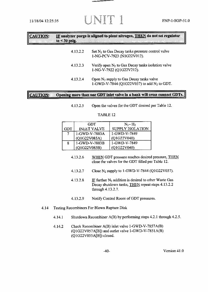
11/18/04 12:25:35 IkJ lN JM- 11 1 FNP- 1-SOP-5 1.0
........... I.. ..............................1~ 4 041a: aw]azN .4- : W . ................................... I..'' ............................. I........ .. ..............-............:M g ................................ .............................................................................. ..... ..... t o ........... 11.11, .............
4.13.2.2 Set N2 to Gas Decay tanks pressure control valve
1 -NG-PCV-7923 (NI1G22 VO 12).
4.13.2.3 Verify open N2 to Gas Decay tanks isolation valve1-NG-V-7922 (Q1IG22V2 12).
4.13.2.4 Open N2 supply to Gas Decay tanks valve
1 -GWD-V-7844 (Q1IG22V03 7) to add N2 to GDT.
Ik~ill~k: penlu morehan oe CDTlalot~e Joa ban willcros .... c O~s
4.13.2.5 Open the valves forthe GDT desired per Table 12.
TABLE 12
GDT N2 -112GDT INLET VALVE SUPPLY ISOLATION
7 1-GWD-V-7883A 1-GWD-V-7849(Q1G22V085A) _ (Q 1G22V040)
8 1-GWD-V-7883B 1-GWD-iV-7849___(Q 1G22V085B) (Q 1G22V040)
4.13.2.6 WHEN GDT pressure reaches desired pressure, TI-ENclose the valves for the GDT filled per Table 12.
4.13.2.7 Close N2 Supply to I1-GWD-V-7844 (Q1IG22V037).
413.2.8 IF further N2 addition is desired to other Waste GasDecay shutdown tanks, THEN repeat steps 4.13.2.2through 4.13.2.7.
4.13.2.9 Notify Control Room of GDT pressures.
4.14 Testing Recombiners For Blown Rupture Disk
4.14.1 Shutdown Recombiner A(B) by performing steps 4.2.1 through 4.2.5.
4.14.2 Cheek Recombiner A(B) inlet valve I1-CWD-V-7857A(B)(Q1IG22V057A[B]) and outlet valve I1-GWD-V-7851IA(B)(Q I G22V055A[B]) closed.
-40- -40- Version 41.0

11/18/0412:25:35 FNP-1-SOP-51.0
4.18 Swapping Gas Compressors While In Service
NOTE: When opening 1-CCW-V-045A(B), CCW from 1A(1B) WGC, FI-3085 willalready be indicating 50 gpm for the operating compressor. This gauge'smaximum indication Is 90 gpm. 1-CCW-V-045A(B) (N1P17VO45A[BJ) mustbe adjusted until F1-3085 indicates slightly greater than 90 gpm.
4.18.1 Verify open the following valves on the compressor to be placed inservice:
* 1-CCW-V-043A(B) (N1P17VO43A[B]), CCW to 1A(IB) WGC
* I-CCW-V-045A(B) (NIP17VO45A[B]), CCW from IA(lB) WGC
* 1-GCWD-V-7909A(B) (Q1G22V063A [B]), RMW to 1A(IB) WGC
* 1-GWD-V-7907A(B) (Q1G22V061A [B]), IA(1;B) WGC suction
* I-GWD-V-7910A(B) (QIG22V064A[B]), IA(IB) WGC discharge
4.18.2 Start the waste gas compressor being placed in service.
4.18.3 Stop the waste gas compressor being removed from service.
4.18.4 Close I-CCW-V-045A(B) (NIP17V045A[B]), CCW from 1A(lB)WGC on the waste gas compressor being removed from service.
4.18.5 Adjust I-CCW-V-045A(B) (NIP17VO45A[B]), CCW from IA(IB)WGC for the on service compressor until FI-3085 indicates 50 gpm.
4.19 Transferring Gas Between Gas Decay Tanks With The System Shutdown
4.19.1 Have Chemistry sample the appropriate gas decay tanks to ensure a
compatible mixture exists.
4.19.2 Notify the counting room of the waste gas transfer.
:1fl2Q:g- T:tl oig wase 1cal ethO. ale seal water he t1jM b gr fJr tiheeoinelprntr sotIn uninnst remain:100d 0 when the oImpressohsor0 i t J
4.19.3 Adjust water flow through I A(11B) WGC seal water heat exchanger to50 gpm on FI-3085 by adjusting the cooling water discharge valveN1P17VO45A(B).
-47 - Version 41.0

11/18/04 12:25:35 II '" }< ' FNP- 1 -SOP-51.0
4.19.4 Using Table 14,following steps.
determine the valve numbers required and perform the
TABLE 14
GDT Outlet GDT Inlet GDT Bank GDT BankGDT Bank Valve Valve Inlet Valve Outlet Valve
I A I-(iWD-V-7823A I-GWD-V-7820A 1-GWD-V-7818 1-CGWD-V-7825. 1G22VO19A) (QIG22V025A) (QIG22V029) (Q O 17)
2 A I-GWD-V-7823B I-GWD-V-7820B 1-GWD-V-7818 1-GWD-V-7825(Q1IG22V019B) (QIG22V025B) (Q1G22V029) (Q 1(22V017)
3 A 1-GWD-V-7823C I-GWD-V-7820C 1-GWD-V-7818 I-GWD-V-7825_ _ (QIG22V019C) (QIG22V025C) (QI G22V29) (QI,22O 17)
4 B I-GWD-V-7833A I-GWD-V-7830A I-GWD-V-7828 I-GWD-V-7835(QIG22V022A) (QIG22V026A) Q 2V30) (Q 2V020)
5 B 1-GWD-V-7833B I-GWD-V-7830B I-GWD-V-7828 I-GWD-V-7835_ _ (QlIG22V022B) (IG22V26B) 0 ) (Q1(i22V020)
6 B 1-GWD-V-7833C I-GWD-V-7830C I-GWD-V-7828 I-GWD-V-7835(Q1022V022C) (QI022V026C) (Q1G22V030) (QIG22V020)
7 Shut I-GWD-V-7886A I-GWD-V-7883A I-iWD-V-7881 I GWD-V-7888Down (1022V74A) (QV085 (QG22V083) (Q IG22V076)
8 Shut I-GWD-V-7886B I-GWD-V-7883B I-GWD-V-7881 I GWD-V-7888Down (Q1G22V074B) (QIG22VOS5B) (1 22V O8 (Q 2 6)
4.19.5 Open the GDTbe transferred.
bank outlet valve for the bank from which the gas is to
4.19.6 Open the Outlet Valve for the GDT from which the gas is to betransferred.
4.19.7 Close the Outlet Valve for the GDT where the gas is to be transferred.
4.19.8 IF transferring gas to another bank, THEN close the GDT Bank OutletValve for the bank where the gas is to be transferred.
4.19.9 Bypass the recombiner as follows:
4.19.9.1 Open Recombiner Bypass Valve 1-GWD-V-7855(Qi G22V044).
4.19.9.2 Verify closed Compressor Disch to Recombiner Iso1-GWD-V-7856 (QIG22V045).
4.19.9.3 Verify closed Recombiner Dischg to GDTI-GWD-V-7852 (QIG22V041).
4.19.10 Open the GDT Bank Inlet Valve for the bank where the gas is to betransferred.
-48- Version 41.0

11/18/04 12:25:35 G FNP-1-SOP-51.0
4.19.11 Open the Inlet Valve for the GDT where the gas is to be transferred.
4.19.12 Close the Inlet Valve for the GDT from which the gas is to be
transferred.
4.19.13 IF transferring gas to another bank, THEN close the GDT Bank InletValve for the bank from which the gas is being transferred.
4.19.14 Verify open GDTs outlet iso I -GWD-V-7815 (Q IG22V0 15).
4.19.15 Transfer as much gas as possible by holding the A(B) compressorhandswitch in the RUN position.
4.19.16 WHEN as much gas as possible has been transferred, TIIEN stop thecompressor.
4.19.17 Close GDTs outlet iso I-GWD-V-7815 (QIG22V0 15).
4.19.18 Close the GDT Outlet Valve on the tank from which the gas wastransferred.
4.19.19 Close the inlet valve for the GDT where the gas was transferred.
4.19.20 Close the GDT Bank Outlet Valve for the bank from which the gas
was transferred.
4.19.21 Close the GDT Bank Inlet Valve for the Bank where the gas was
transferred.
4.19.22 Close Recombiner Bypass Valve l-GWD-V-7855 (QIG22V044).
4.19.23 Close waste gas compressor A(B) cooling water discharge valveI -CCW-V-045A(B) (N 1P17V045A[B]).
4.19.24 Notify the Counting Room of the waste gas transfer AND have the
transfer logged in the reactor operator log in the Control Room.
4.20 Waste Gas System Leak Check and Startup With The Recombiners Bypassed
:0000000Th chlie ate dsehwvegif heseal-wt WAO'heotge~agger. for the:00|iEE;0000000000000ig~gigi:0ggg~EE~i~i ....pre.or .......... g tean cesiw en le~n g tssr s~nt~i~;000g_ _ai
-49- Version 41.0

QUESTIONS REPORTfor HLT-29 rebuttal Questions
G2.3.2 001/3/3/ALARA/MEM 2.5/2.9/BANK/FAOI 1005./RO,
Question 65:
A valve four feet inside a valve room is producing a 0.2 R/hr field at one feet(30 centimeters) from the valve.
Which one of the following identifies the proper posting requirement for this room?
A. CAUTION, RADIATION AREA
Br CAUTiON, HIGH RADIATION AREA
C. DANGER, EXCLUSION AREA
D. GRAVE DANGER, VERY HIGH RADIATION AREA
Tuesday, January 25, 2005 1:04:02 PM 11

QUESTIONS REPORTfor HLT-29 rebuttal Questions
A. Incorrect - this is 200 mr/hr and is too high for a radiation area.
B. Correct- CAUTION, HIGH RADIATION AREA
C. Incorrect - an exclusion area is > 1 rem/hr
D. Incorrect- not high enough for this designation
Reference:CFR: 43.4 /45.10 OPS-30401A, Health Physics
POSTINGS DOSE RATE (mrem/hr) DISTANCE FROM SOURCE
Radiation Area > 5 but < 100 30 cm (12 inches)
High Radiation Area > 100 30 cm
Exclusion Area > 1000 or at HP Mgr's Direction 30 cm
Very High Radiation Area > 500 rads/hr I meter
Types of PostingsSeveral different types of radiological conditions may exist in the plant. High radiation levels andcontaminated areas are some examples. Before entering any type of radiological area, you must meet therequirements of the RWP. The following are common types of postings that may be encountered in theplant, and what they mean:* Radiation Controlled Area - this is an area with restricted access to make individuals knowledgeable ofpossible exposure to radiation and radioactive material.* Radiation Area - This is an area with a dose rate greater than 5 mrem per hour, 30 cm (appox.12") fromthe source of radiation. It is posted with a 4-sided rectangle shaped sign.* High Radiation Area (See Figure 13) - This is an area with a dose rate of greater than 100 mrem perhour, 30 cm (appox.12") from the source. This is posted with a triangle shaped (3 sided) sign.* Exclusion Area (See Figure 14) - This is a special type of High Radiation Area where you could receivegreater than one rem/hr at 30 cm (appox. 12'). The access to this area is normally locked due to the high
dose rate. (This area is posted with an 8-sided sign that is the same shape as a traffic control stop sign.)Very High Radiation Area (See Figure 15) - This is an area which has the words "GRAVE DANGER,VERY HIGH RADIATION AREA". This area has the potential of being greater than 500 rad(usually same as rem) per hour at 1 meter.Very High Radiation Areas will be controlled similar to "Exclusion Areas", with additional measures taken
to ensure that an individual is not able to gain unauthorized or inadvertent access to the area. This isposted with an 8-sided sign (shaped like traffic control stop sign).
Tuesday, January 25, 2005 1:04:02 PM 12

QUESTIONS REPORTfor HLT-29 rebuttal Questions
G2.3.2 Radiation Control - Knowledge of facility ALARA program.
List four types of areas posted based on radiation levels and the radiationlevels/distances that require them to be posted (OPS30401A22).
Describe the posting and entry requirements for a High Radiation Area.(GEN40103E-01)
Describe the posting and entry requirements for an Exclusion Area.(GEN40103E-02)
Describe the posting and entry requirements for a Very High Radiation Area.(GEN401 03E-03)
Identify the following radiological areas and postings: (GEN40103D-01)* Radiation Controlled Area (RCA)* Radiation Area* High Radiation Area (HRA)* Exclusion Area* Very High Radiation Area (VHRA)* Airborne Radioactivity Area* Radioactive Materials Area* Radiologically Restricted Area (RRA)
HEALTH PHY-30401A22 #19
Tuesday, January 25, 2005 1:04:02 PM 13

QUESTIONS REPORTfor HLT-29 rebuttal Questions
POSITION:
Upon review, one individual picked 'A" as the correct response. We contend that both responses "A" and"B" are correct depending on factors that are not provided in the stem of the question. A review of plantand NRC Health Physics policies and Reg. Guides revealed the following:
* From the "Floor Walk down" checklist posted on the health physics home page - Minimize the sizeof each area posted to just the area affected. (e.g. If just 1 corner of a room is a High Radiation Area,only post that portion of the room as a HRA and not the entire room) This would justify "A" as the correctresponse for a larger room. Since the High Radiation Area (HRA) posting would only be required at a
distance of 1.5 ft. from the source (boundary of 100 mrem/hr field, it would not necessarily require postingthe entrance to the room as a HRA. In this question the entrance is four feet away.
* From Regulatory Guide 8.3.8, Control of Access to High and Very High Radiation Areas Section
2.5 - Controls (e.g., locked doors, access control, and posting) for high radiation areas may beestablished at locations beyond the immediate boundaries of high radiation areas to take advantage ofnatural or existing barriers. Smaller rooms, rooms that access is restricted due to other reasons (i.e.contamination levels) or rooms that has physical limitations that preclude posting the HRA at is smallestpossible boundary are routinely posted at their entrance. Since this information was also not given in thestem, this could also lead one to pick response "B" as a conservative answer.
Practical experience as a System Operator where high radiation areas in larger rooms are posted closerto actual boundaries based on the radiation fields rather that the door to the room led one particularcandidate to choose response "A" after ascertaining the dose at the entrance 4' away was <100 mrem anhour. This is consistent with the posting practices of the FNP Health Physics department. The facts are
that the high rad area would be posted at approx. 1.5 feet from the source, and at the entrance thereading would be 12.5 mr/hr. This would not constitute a high rad area posting for the entire room.
This question asks for the posting of a certain valve room. Most valve rooms are very small in nature butat FNP, there are several extremely large valve rooms that may have more than one entrance. One in
particular is the piping penetration room which has an extremely large number of valves and areas. In1986, a committment to the NRC was written that speaks of this subject. If a room is large, and in an
effort to reduce the size of the boundaries of high rad areas, only the area around the high rad area wouldbe posted. For smaller rooms or cubicles, the entire cubicle would be posted as a high rad area.
Enclosed In the commen3ts are two maNs performed at FNP on 01/0712005 and one from 0111812005
that shows this is how we do business at FNP.
RECOMMENDATION:
We submit based on these facts that both answers "A" and "B" are correct.
Hypothesis of why the exam team missed this on review.During the validation process no one missed this question. The exam team did not
effectively evaluate that a valve room could be large. We were wrong and missed themark on this question.
Tuesday, January 25, 2005 1:04:02 PM 14
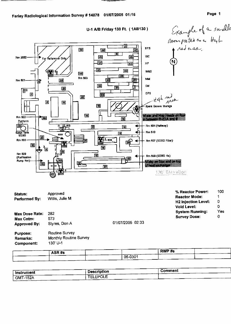
Farley Radiological Information Survey # 14878 0110712005 01:16 Page 1
U-1 A/B Friday 130 Ft. ( 1AB130 )
A' /1CS t...nt,.
* 4& - vc
i 42 4 v,
Status:Performed By:
Max Dose Rate:Max Cntm:Approved By:
Purpose:Remarks:Component:
ApprovedWillis, Julie M
% Reactor Power:Reactor Mode:H2 Injection Level:Void Level:System Running:Survey Dose:
10010
0Yes0282
573Styres, Don A 01/07/2005 02:33
Routine SurveyMonthly Routine Survey130' U-1
j Kwr ws jASR Us I I I KRWP #s -I
II I 05-0301 I I
IGst ume2 Description Comment

Farley Radiological Information Survey # 15029 01/1812005 16:32 Page 1
-x4rY1- 2~ - 0"U-1 A/B Tuesday 121ft ( 1AB121I)
&-1~t-i-b -Ji &w 4 ~S tJ
I To Elevator -
1 _
AC,-efr
Status:Performed By:
ApprovedPate, Mark H
% Reactor Power:Reactor Mode:H2 Injection Level:Void Level:System Running:Survey Dose:
1001
00No2Max Dose Rate:
Max Cntm:Approved By:
N/ANDGMTRoper, Wally H 01/18/2005 17:22
Purpose:Remarks:Component:
Specific SurveyPost Decon SurveyU-1 121' PPR
and release of area.
ASRI#s RWP #s
05-0301 105-0801
|Instrument Dscription j_- Comment== =

FLOOR WALKDOWNS
* Ensure all posting ropes are TAUT* Ensure all posting ropes are attached to stanchions, bracing or other
appropriate point of attachment (i.e. not taped to walls), and that therope is not frayed or otherwise showing signs of wear (e.g. faded,cracking, etc.).
* Ensure Contaminated Area signs have location of NEAREST friskerindicated on back of sign
* Ensure SOP are in place where needed, positioned to allowindividual to safely undress, situated to minimize exposure to sourcesof radiation as much as possible, and neatly secured
* Stanchions should be positioned outside the contaminated area, onlywhen there are physical restrictions on space should the stanchionsbe placed inside the contaminated area, but they must be at the outerperimeter of the contaminated area.
* Minimize the size of each area posted to just the area affected. (e.g.If just 1 corner of a room is a High Radiation Area, only post thatportion of the room as a HRA and not the entire room; if the pumpshaft area is contaminated, only post that area, not the entire pumpskid or the entire pump room).
* Ensure laundry and trash receptacles are reasonably available atposted contaminated areas
* Ensure all openings on hoses, vent bottles, vacuums, NPUs, etc arecovered, preferably with a bag or other similar device [tape coveringopenings can come loose or not fully cover the opening].
* Ensure hoses, cords, etc routed from clean areas to contaminatedareas are secured to prevent cross contamination of clean areas. It isdesirable to use tywraps, Velcro straps, or similar material as thefirst choice for securing and to use tape as the last choice for securingthe items at the contamination boundary.
* Ensure no items are partially inside contaminated area boundaries.* The use of various types of radiological tape should generally be used
in some combination with ropes and stanchions. If an area is to beposted for less than 1 shift, it is generally acceptable to not requiretape to be put down.
* Small areas (e.g. drains, small area on floor, etc.) may be identifiedas contaminated by just the use of the appropriate radiological tape.

* Use signs that are clean and legible (not tape residue or taped over
sections of the sign).
* Use signs indicating multiple conditions for posting when available
(Example: if area is contaminated and is a radiation area use
Radiation Area/Contaminated Area sign or Radiation Area Sign
with an insert for Contaminated Area, versus 1 Radiation Sign + 1
Contaminated Area sign).
* Make sure we post, as appropriate, any "Sources of Radiation"
areas, any "Low Dose Waiting Areas", and any "Hot Spot" areas.
* Ensure all containers are tagged as necessary
* Ensure information on Rad tags are accurate, complete, and legible,
if the RAM tags are accurate and legible, there is no need to replace
them; however, if they do not meet these criteria, they are to be
replaced.* Ensure most recent copies of surveys are neatly posted in work area
and just inside the RCA entrance on the survey map boards (any
updates to posted surveys should be made in red and updated in the
survey notebook in the HP Office).* Correct incidental housekeeping items
* Report housekeeping items that require other groups attention
and/or support via the Housekeeping database or other appropriate
means ( follow-up on reported items for completion and inform HP
FRM of items not corrected within 3-5 days)
* Submit MSR /DR for deficiencies (i.e. leaks, inoperable equipment,
etc)* Request FAC to install catch devices to contain leaks to reduce
potential of spread of contamination
* Submit BULB request for any areas where bulbs are blown
* Report any needs for trash/laundry receptacles to FAC or any
trash/laundry receptacles that need emptying
* Submit areas that can be potentially released as clean to FAC group
* Check to make sure there are no cloth covered chairs or stools inside
any RCA. Remove any found or notify the HP Foreman if not able
to remove (e.g. locked to some structure)
From Health Physics Web Page.

NRC: Regulatory Guide 8.38 -Control of Access to High and Very High Radiation Areas ... Page 1 of 8
~ tIndex I Shte map I A e lossary IontactUs A
~U.S. Nuclear Regulatory Commission iHoe hoW Ae9 ht eDoI Nuclear Nucdear flRadioactive Facility Info Public
Homte > Electronic ReadingqRQom > 2oqurmnq t;Collections > Reggktpry Guffe$ > Occupational H-19Latl > Regulatory Guide S
Regulatory Guide 8.38 - Control of Access to High and Very Higi'
Radiation Areas in Nuclear Power Plants
(Draft was issued as DG-8006)
June 1993
Availabilimty Notce
Contents
• A. INTRODUCTION* B. DISCUSSIQN* C.,-REGULATORY-POSITION* D. 2 VI.LEM.E.NTATION
A. INTRODUCTION
Section 20.1101, "Radiation Protection Programs," of 10 CFIR Part 20, 'Standards for Protection AgainstRadiation," requires licensees to develop and implement a radiation protection program appropriate to thescope of licensed activities and potential hazards. Section 20.2102 requires licensees to document theseprograms. An important aspect of a radiation protection program at nuclear power plants is the institution of a
system of controls that includes procedures, training, audits, and physical barriers to protect workers againstunplanned exposures in high and very high radiation areas. Specific requirements applicable to controllingaccess to high radiation areas are in 10 CFR 20.1601, and additional requirements to prevent unauthorizedentry into very high radiation areas are in 10 CFR 20.1602. This regulatory guide describes methodsacceptable to the NRC staff for implementing these requirements.
Underwater divers are being used more often for inspections and maintenance in reactor cavities and spentfuel pools. These underwater operations require careful planning, proper work methods, and specificprocedures because of the potential for significant overexposures from irradiated fuel elements and irradiatedreactor components and structures that act as high-level radiation sources.
Appendix A to this guide contains procedures for good operating practices for underwater divers that arerecommended for licensees. These practices have evolved, in part, from instances in which proper controlswere not in place or were not implemented. Appendix B summarizes past experiences with very high andpotentially very high radiation areas so that historical, yet pertinent, information is readily accessible to users,especially to newer personnel.
Any information collection activities mentioned in this regulatory guide are contained as requirements in 10CFR Part 20, which provides the regulatory basis for this guide. The information collection requirements in 10CFR Part 20 have been approved by the Office of Management and Budget, Approval No. 3150-0014.
htt:Hww~nc~gvlradng-mldc-clletiosleg-uidslocuptioalheathlctiel838 .. 1/2012005

NRC: Regulatory Guide 8.38 - Control of Access to High and Very High Radiation Areas... Page 2 of 8
B. DISCUSSION
Requirements intended to prevent inadvertent, unwarranted, and potentially dangerous overexposures of
individuals at facilities licensed by the NRC are provided in 10 CFR 20.1601 and 20.1602. A framework of
graded radiation protection procedures is recommended in this guide to ensure that the controls for access to
high and very high radiation areas at nuclear power plants are appropriate to the radiation hazard during both
normal operations and abnormal operational occurrences.
Dose rates in areas of nuclear power plants accessible to individuals can vary over several orders of
magnitude. High radiation areas, where personnel can receive doses in excess of the regulatory limits in a
relatively short time, require special controls. Very high radiation areas require much stricter monitoring and
controls since failure to adequately implement effective radiological controls can result in radiation doses thatresult in a significant health risk.
For the purpose of this guide, a high radiation area is defined as an area, accessible to individuals, in which
radiation levels could result in an individual receiving a deep dose equivalent in excess of 0.1 rem (1 mSv) in
1 hour at 30 centimeters from the radiation source or from any surface that the radiation penetrates. A very
high radiation area means an area, accessible to individuals, in which radiation levels could result in an
individual receiving an absorbed dose in excess of 500 rads (5 grays) in 1 hour at i meter from a radiation
source or from any surface that the radiation penetrates. An accessible area is defined as one that can
reasonably be occupied by a major portion of an individual's whole body, which is defined in 10 CFR 20.1003.
C. REGULATORY POSITION
1. PROGRAM ELEMENTS
Licensees are required by 10 CFR 20.1101 to develop and implement a radiation protection program
appropriate to the potential radiation hazards in their facility. Because of the potential for overexposure in
high and very high radiation areas, it is important that licensees have effective programs for controlling access
to these areas. There have been instances of personnel inadvertently entering these areas because ofinadequate controls on access.
The following elements should be included in the plant procedures and practices for access control to be sure
that personnel are protected in high and very high radiation areas.
1.1 Management Control
Facility management has the responsibility for developing, implementing, and enforcing access controlprocedures for high and very high radiation areas.
1.2 Procedural Controls
1.2.1 Access control procedures for high and very high radiation areas should address at least the following
areas:
1. Job planning,
2. Radiation protection coverage,
3. Survey techniques and frequencies,
4. Training of workers,
5. Prework briefing,
6. Frequency for updating radiation work permits (RWPs) or their equivalent, and
http:H/www .nrc.govlreading-rm/doc-collectionslreg-guidesloccupatio)nal-health/active-3 8. ... 1/20/2005

NRC: Regulatory Guide 8.38 - Control of Access to High and Very High Radiation Areas... Page 3 of 8
7. Placement of measuring and alarming dosimeters.
1.2.2 Administrative procedures should address the management oversight and specific control measures
needed for entry into high and very high radiation areas. The procedures should include the process for
gaining entry to these areas, such as the control and distribution of keys.
1.2.3 Procedures for activities that can greatly increase in-plant radiation levels (i.e., the withdrawal of in-
core detectors, thimble tubes, or transversing in-core probes from the reactor) should provide for notification
of personnel likely to authorize or have access to affected areas.
1.2.4 Procedures should provide for timely surveys to identify and post with precautionary notices the areas
and systems that may become high or very high radiation areas, especially when in-plant changes (e.g., spent
fuel transfer operations) could alter the ambient radiation levels.
1.2.5 Procedures should be provided to verify, at least on a weekly basis, that proper controls such as posting
and barriers are in place for restricting access to high and very high radiation areas.
1.3 Training
The types of controls required for entry into high and very high radiation areas should be included in training
for radiation workers (both initial and requalification training). Areas in the plant that are known to have the
potential for becoming very high radiation areas should be specifically identified.
1.4 Communications
Good communication is essential among all departments concerned with entry into high and very high
radiation areas to prevent excessive and unwarranted radiation exposures. This communication is especially
important among personnel in known potential or existing very high radiation areas, such as reactor cavities,
spent-fuel transfer areas, spent-fuel pools, and other reactor components and tanks. The access control
program should include procedures and provisions for the use of equipment to ensure adequate
communication. The group or department responsible for radiation protection should be notified prior to any
entry into a very high radiation area.
1.5 Physical Controls
Physical barriers (such as chain-link fencing or fabricated walls) may be used to prevent unauthorized
personnel access to high and very high radiation areas. Physical barriers surrounding high radiation areas
should be sufficient to prevent inadvertent entry (e.g., a 2-meter [6-foot] fence, with worker training and
signs or procedures to deter climbing, may be adequate for controlling access to a high radiation area).
Physical barriers should, to the extent practicable, completely enclose very high radiation areas sufficient to
thwart"l) undetected circumvention of the barrier (i.e., fencing around very high radiation areas should extend
to the overhead and preclude anyone from climbing over the fencing). Entrances or access points to these
areas should be controlled, as described in Regulatory Positions 2 through 4. Physical controls should be
established that do not preclude personnel access to these areas when access is required to respond to
emergencies.
Implicit in the definition of an entrance or access point to a high radiation area is that the opening (or portal)
itself is accessible to personnel. Openings in physical barriers around a high radiation area are not required to
be controlled as entrances if exceptional measures are needed to access them. Examples of areas that do not
need to be controlled as entrances are the manway to a tank or vessel that has its cover bolted in place or an
opening in a shield wall that is physically difficult to access without a ladder or mobile platform.
An acceptable method of excluding personnel from areas with dose rates greater than 1 mSv (100 mrem) in 1
hour is to provide a substantial physical barrier (e.g., chain-link fencing) that completely encloses the area
and has no openings or portals. This type of control is commonly called cocooning. Since these areas are not
accessible, the control of access and posting requirements in 10 CFR Part 20 for high and very high radiation
areas do not apply. However, the requirements in 10 CFR Part 19 to instruct the worker on the radiological
hazards in these areas are applicable.
http:H/www.nrc.govlreading-rniloc-collectionslre~g-guidesloccupational-healt~activel8-38 .... 1/20/2005

NRC: Regulatory Guide 8.38 - Control of Access to High and Very High Radiation Areas... Page 4 of 8
Note: When an inaccessible portal to a high radiation area is made accessible (e.g., a manway cover is
removed or scaffolding is erected) or when a portal is created in a physical barrier (i.e., a cocoon is breached),
the applicable controls for a high or very high radiation area must be provided.
Controls must be established that prevent personnel from being locked in a high radiation area (10 CFR
20.1601(d)). For example, if chains and padlocks are used, the procedural controls must prevent the area
from being locked with personnel in the area. If doors are self-locking, personnel must be able to open themfrom the inside without a key (10 CFR 20.1601(d)).
1.6 Shielding
Shielding may be used to make a high or very high radiation area, or a potentially very high radiation area,
inaccessible. The following guidelines apply to shielding used for the purpose of controlling access.
1. The shielding should not be readily removable. Blankets, bricks, or other portable shielding that could
be moved by hand would be readily removable; however, shielding requiring a hoist or crane to movewould not be considered readily removable.
2. If the shielding is removable, it should be posted with a warning sign such as: 'Warning, do notremove. Dangerous radiation levels may result.'
3. If the shielding is removable, local radiation monitors with audible and visible alarms should be installed
to warn personnel of the high exposure rates created by removal of the shielding.
2. HIGH RADIATION AREAS
2.1 Options for Access Control
Of the options for access control provided in 10 CFR 20.1601(a), the most widely used procedure at nuclear
power plants is keeping high radiation areas locked. Although licensees have the option to control high
radiation areas with the use of a control device to reduce radiation levels when an individual enters the area
or the use of an alarm to alert the individual and the supervisor to an entry into a high radiation area,
experience has shown that these options have limited practical application at nuclear power plants. In addition
to the provisions of 10 CFR 20.1601(a), a nuclear power plant licensee may apply for Commission approval of
alternative methods for control under 10 CFR 20.1601(c). See Regulatory Position 2.4 below.
2.2 Positive Access Control
Positive control over each individual entry is required by 10 CFR 20.1601(a)(3) when access is required to a
high radiation area that is normally controlled by being locked. In a large facility such as a nuclear power
plant, appropriate positive access controls can be instituted through the use of radiation work permits (RWPs)
or an equivalent program. Such a system ensures appropriate supervision through specific procedures that
establish requirements for control and delegate responsibility to qualified individuals. Procedures forestablishing positive control over each entry should provide for:
1. Surveys that identify the radiation hazards in the area should be made and the results documented;
2. An appropriate level of supervision to determine that exposure of the individual to the hazards is
warranted;
3. Communication of the nature and extent of the radiation hazards to each individual entering the area;
4. Protective measures (e.g., shielding, time limits, protective clothing, monitoring) to protect the
individual from excessive or unnecessary radiation exposure; and
5. Permission for only authorized individuals to enter the high radiation area with all entries and exitsdocumented.
http:Iwww.nrc .govlreading-rm/doc-collectionslreg-guidesloccupational-healthlactivel8-38. ... 1/20/2005

NRC: Regulatory Guide 8.38 - Control of Access to High and Very High Radiation Areas... Page 5 of 8
2.3 Direct or Electronic Surveillance
Direct or electronic surveillance is identified in 10 CFR 20.1601(b) as a substitute for the controls required in
10 CFR 20.1601(a). The direct or electronic surveillance should have the following capabilities as a minimum.
1. Detect attempted unauthorized entry,
2. Warn individuals that their attempted entry is unauthorized, and
3. Alert the proper authority about an unauthorized entry so that action can be taken to correct the
situation.
2.4 Alternative Methods for Access Control
The requirements in 10 CFR 20.1601(a) for access to high radiation areas may, in some instances, cause
unnecessary restrictions on plant operations. According to 10 CFR 20.1601(c), licensees may apply to the
Commission for approval to use alternative methods for control. The following method is acceptable to the
NRC staff as an alternative to the requirements in 10 CFR 20.1601(a) for the control of access to high
radiation areas.
Each high radiation area as defined in 10 CFR Part 20 should be barricaded' ' and conspicuously posted as a
high radiation area, and entrance thereto should be controlled by requiring issuance of a radiation work permit
(RWP) or equivalent. Individuals trained and qualified in radiation protection procedures (e.g., a health
physics technician) or personnel continuously escorted by such individuals may be exempted from this RWP
requirement while performing their assigned duties in high radiation areas where radiation doses could be
received that are equal to or less than 0.01 Sv (1.0 rem) in 1 hour (measured at 30 centimeters from any
source of radiation) provided they are otherwise following plant radiation protection procedures, or a general
radiation protection RWP, for entry into such high radiation areas. Any individual or group of individuals
permitted to enter such areas should be provided with or accompanied by one or more of the following:
* A radiation monitoring device that continuously indicates the radiation dose rate in the area,
* A radiation monitoring device that continuously integrates the radiation dose rate in the area and
alarms when a preset integrated dose is received. Entry into such areas with this monitoring device
may be made after the dose rates in the area have been determined and personnel have been made
knowledgeable of them,
* An individual qualified in radiation protection procedures with a radiation dose rate monitoring device.
This individual is responsible for providing positive radiation protection control over the activities within
the area and should perform periodic radiation surveillance at the frequency specified in the radiation
protection procedures or the applicable RWP.
In addition, areas that are accessible to personnel and that have radiation levels greater than 0.01 Sv (1.0
rem) (but less than 500 rads at I meter) in 1 hour at 30 cm from the radiation source, or from any surface
penetrated by the radiation, should be provided with locked doors to prevent unauthorized entry, and the keys
should be maintained under the administrative control of the shift supervisor on duty or health physics
supervisor. Doors should remain locked except during periods of access by personnel under an approved RWP
that specifies the dose rates in the immediate work areas and the maximum allowable stay time for
individuals in that area. In lieu of a stay time specification on the RWP, direct or remote continuous
surveillance (such as closed circuit TV cameras) may be made by personnel qualified in radiation protection
procedures to provide positive exposure control over the activities being performed within the area.
Individual high radiation areas that are accessible to personnel, that could result in radiation doses greater
than 0.01 Sv (1.0 rem) in 1 hour, and that are within large areas where no enclosure exists to enable locking
and where no enclosure can be reasonably constructed around the individual area should be barricaded and
conspicuously posted. A flashing light should be activated as a warning device whenever the dose rate in such
an area exceeds or is expected to exceed 0.01 Sv (1.0 rem) in 1 hour at 30 cm from the radiation source or
from any surface penetrated by the radiation.
http:/www.nrc.govlre~ading-rl~doc-collectionslreg-guidesloccupational-healthlactivelS-38 .... 1/20/2005

NRC: Regulatory Guide 8.38 - Control of Access to High and Very High Radiation Areas... Page 6 of 8
2.5 Controls for High Radiation Areas (Control Points and Barriers)
Controls (e.g., locked doors, access control, and posting) for high radiation areas may be established atlocations beyond the immediate boundaries of the high radiation areas to take advantage of natural or
existing barriers. The use of one locked door, or one control point where positive control over personnel entry
is exercised, to establish control over multiple high radiation areas is acceptable provided the followingconditions are met:
1. The individual high radiation areas are barricaded and posted separately to identify the actual areas of
concern,()
2. Control points are established sufficiently close to the high radiation areas that adequate supervision ofaccess to the areas can be assured, and
3. The required protective measures and other requirements for entering the high radiation areas (e.g.,
dosimetry, monitoring) are enforced at the control point.(4)
2.6 Control of Keys
The shift supervisor or the radiation protection manager (or their respective designees) should
administratively control the issuance of keys to personnel requiring access to high radiation areas and thereturn of the keys.
3. VERY HIGH RADIATION AREAS
Because of the potential danger of life-threatening overexposures to individuals, extremely tight control must
be maintained over any entry to very high radiation areas. According to 10 CFR 20. 1602, licensees mustinstitute additional measures to ensure that an individual is not able to gain unauthorized or inadvertent
access to very high radiation areas. To the extent possible, entry should be forbidden unless there is a sound
operational or safety reason for entering. Special consideration should be given to areas that become very
high radiation areas when the plant changes operational modes, such as shutdowns or startups.
3.1 Entrances
Entrances to very high radiation areas should be kept locked except during periods when access to the areas
is required (see 10 CFR 20.1601(a)(3)). Posting of very high radiation areas is required by 10 CFR 20.1902.
Multiple very high radiation areas may be controlled with one locked entrance to take advantage of natural or
existing barriers. For example, several very high radiation areas inside the containment, with the reactor at
power, may be controlled by locking the containment access port. However, each very high radiation areawithin these areas should also be conspicuously posted and barricaded separately. Controls for personnelaccess to very high radiation areas should be established at the locked entrance.
Authorized entries to very high radiation areas may be monitored by continuous direct electronic surveillance.
Unauthorized entries to very high radiation areas inside a PWR containment at power can be controlled bylocking containment access. However, during authorized entry of the containment at power, electronic
surveillance is an acceptable method to ensure that unauthorized entries do not occur into posted andbarricaded very high radiation areas within the containment.
3.2 Control of Keys
The following procedures should govern the administrative control of keys to very high radiation areas.
1. Procedures should be established so that (1) there are stricter requirements for issuance of keys to
very high radiation areas than keys to high radiation areas, and (2) the responsible operations andradiation protection supervisors are notified prior to personnel entry to very high or potentially veryhigh radiation areas.
http :lww w. rc. govlreading-}rdoc-collectionslreg-guidesloccupationa-healthlactive/8-38 ... 1/20/2005

NRC: Regulatory Guide 8.38 - Control of Access to High and Very High Radiation Areas... Page 7 of 8
2. A key for access to a very high radiation area should unlock only that area. Master keys that unlockmore than one area may be established for use during emergency situations provided their distributionis limited and they are not used for normal personnel access.
3.3 Radiation Work Permits
Entries to very high radiation areas should be controlled by issuance of a specific RWP or equivalent. General,standing, or blanket RWPs should not be used for controlling entries to very high radiation areas.
3.4 Radiation Protection Technician
A person entering a very high radiation area should be accompanied to the entryway to that area by aradiation protection technician who can determine the radiation exposure conditions at the time of entry andrender assistance if necessary.
4. SPECIAL AREAS
Special hazards may arise in areas that usually are not very hazardous but have the potential to become veryhigh radiation areas during certain normal plant operations. For example, a PWR reactor cavity sump canchange from a radiation area to a very high radiation area as a result of withdrawal of the retractable incoredetector thimble tubes (see Appendix B).
4.1 Administrative Procedures
Administrative procedures should be established to identify these "special" plant areas and ensure thatappropriate control measures for potentially very high radiation areas are implemented prior to starting anyoperation that could create very high radiation areas.
4.2 Materials
Because of high radioactivity levels from activation and contamination, materials in the spent fuel pools,reactor vessel, and refueling cavities could create a very high radiation area when unshielded. These materialsare normally covered with more than 10 feet of water and are inaccessible to personnel performing dutiesabove the pool surface. Therefore, these pool areas do not have to be controlled as high or very high radiationareas solely because of the materials in them provided that:
1. Control measures are implemented to ensure that activated materials are not inadvertently raisedabove or brought near the surface of the pool water,
2. All drain line attachments, system interconnections, and valve lineups are properly reviewed to preventaccidental drainage of the water, and
3. Controls for preventing accidental water loss and drops in water levels that may create high and veryhigh radiation areas are incorporated into plant procedures.
4.3 Procedures
Written procedures for any diving operations into pools, tanks, or cavities, or for access to plant componentsthat contain or may contain highly radioactive materials, should be established to ensure proper radiologicalcontrols. Appendix A discusses some radiological considerations for conducting diving operations that shouldbe incorporated into the plant procedures for diving operations.
4.4 Potential Very High Radiation Areas
Areas of the plant that are known to have a high potential for becoming very high radiation areas duringcertain operational occurrences should be controlled to provide for ready evacuation of the area. An examplewould be the upper drywell in a BWR if an activated fuel bundle is dropped during fuel handling.
D. IMPLEMENTATION
http:llwww.nrc.gov/reading-rrndoc-collections/reg-guides/occupational-healthlactive/8-38... 1/20/2005

NRC: Regulatory Guide 8.38 - Control of Access to High and Very High Radiation Areas... Page 8 of 8
The purpose of this section is to provide information to applicants and licensees regarding the NRC staff'splans for using this regulatory guide.
Except in those cases in which the applicant or licensee proposes an acceptable alternative method forcomplying with specified portions of the Commission's regulations, the methods described in this guide will beused in the evaluation of compliance with 10 CFR Part 20 on control of access to high and very high radiationareas in nuclear power plants.
Footnotes
1. Determined circumvention of a physical barrier, with wire cutters or other tools, cannot be preventedabsolutely. Such instances should be addressed with appropriate disciplinary action.
2. A barricade can be a rope, ribbon, or other firmly secured, conspicuous obstacle that (by itself or used withphysical barriers such as existing walls or hand railings) completely surrounds the area and obstructsinadvertent entry.
3. Relatively small areas with several discrete high radiation areas (i.e., near several valves or components)do not require separate barricades and posting for each if the whole room (or area) is considered a highradiation area.
4. Protective measures for access to an area not posted and barricaded as a high radiation area, but which iswithin a room or area controlled as a high radiation area, may be relaxed commensurate with the radiologicalhazards existing in the area.
Privacy Policy I SitefDisclaimerLast revised Wednesday, December 01, 2004
http://www.nrc.gov/rcading-rmI/do-collections/reg-guides/occupational-healthlactive/ 8-3X ... 1/20/2005

GO-LAS-0 ~6 cr & -7 Vt&& cc-
Commitment
= C: bs 2-Ie
04 kaAcvc- Accce3tatus: PCommitment Number: 0006439 REV#: 002 Commitment Type: Ongoing
SD Number: 0001716 SD Section: SD Page: 0001 SD Rev#: 000 C t.O-
thcSTSD Type: MEMO SD Date: 19860716
SD Title: GUIDANCE FOR POSTING RADIATION AREAS JL QaQo .
Commitment Description: ? Qua."3. GUIDANCE: ITEMS (1) AND (2) ARE NOT MUTUALLY EXCLUSIVE. WHERE MUCH JOF A LARGE AREA FALLS WITHIN THE DEFINITION OF A RADIATION AREA, BUT WHERESAMLLER, DISCRETE AREAS WITHIN THAT AREA HAVE RADIATION LEVELS THAT ARESUBSTANTIALLY ABOVE THE GENERAL AREA LEVELS, IT MAY BE APPROPRIATE AND MOREINFORMATIVE TO THE WORKERS TO:
A. POST, AS A RADIATION AREA, THE ENTRANCES TO THE VERY LARGE ROOM ORBUILDING.
B. DEFINE (AND ALERT WORKERS TO) DISCRETE, SMALLER AREAS OR ROOMS(WITHING THE LARGER, POSTED RADIATION AREA) IN WHICH THE RADIATIONEXPOSURE RATES ARE SUBSTANTIALLY HIGHER THAN THE PREDOMINATEEXPOSURE RATES OF THE LARGER, POSTED AREA.
FNP PRACTICE: THIS GUIDANCE IS FOLLOWED. AN EXAMPLE OF THIS IS THECONTAINMENT BUILDING POSTING FOR NORMAL ACCESS DURING OUTAGES. THECONTAINMENT IS POSTED AS A HIGH RADIATION AREA ON THE BASIS THATSUBSTANTIAL PORTIONS OF THE BUILDING MEET THE HIGH RADIATION AREAREQUIREMENTS. IN ADDiTION, INDIVIDUAL HIGH RADIATION AREAS WITHIN THEBUILDING ARE POSTED SEPARATELY TO WARN WORKERS OF THE INCREASED DOSE RATEIN THESE AREAS."
Responsible Department: FNP-HP Units: 0 Legal Requirement: N
Plant System Codes:NA NOT APPLICABLE
Keywords:RADFNP-HPUNIT1+2REQUIREMENTCONTAINMENTBUILDINGLEVELGUIDANCE
ALLMEMOZ-ID
HIGHRATE
ROOMAREA
NAONGOING
DOSEACCESSEXPOSURE
POSTRADIATION
Action Type: FSAR Update Requireds: N
Unit 1 Unit 2Scheduled----> Comp date:Required-----> Comp date:Actual-------> Comp date:
Unit 1 Unit 2Mstone:
Mstone:Mstone:
PCN Number:.. *... NO DATA .............. ***

WLR Priority:0 0 0 0 0 0 0 0 0 0
Date to Historical: Entry Date: 19870910
Superseded Commitment: Superseding Commitment:
Duplicated Commitment: Duplicating Commitment:
Higher Tier Document Name:
Lower Tier Document Name:
Related LC Numbers:*NO DATA '" ...... ......... "
Closing LC Numbers:
Required Periodic Report Type:
Latest Verification Date:
Last Submittal:
Individual:
MPA Number:***' NO DATA
Commitment Comments:
Procedures:FNP-0-RCP -0000 .0000 05020400 000FNP-0-RCP -0000 .0000 05020300 000FNP-0-RCP -0000 .0000 05020200 000FNP-0-RCP -0000 .0000 000
Miscellaneous:****e********NO DATA ........ . . . ..
Drawing Number / Dwg-Sheet Number / Dwg-Sht-Revision Number...... ....... NO DATA .*.****** *
FNP/Designer Management -----> Date:
Nuclear Support Management --> Date:
CTS Project Engineer --------> Date,

19860716 MEMO 84-082 GUIDANCE FOR POSTING RADIATION AREASLicensing Correspondence
LC #: 0001716 REV#: 009 LC Status: P Entry Date: 19870910
LC Type: MEMO LC Type Number: 84082
LC Date: 19860716 Units: 0 # of Commitments: 003
LC Title: GUIDANCE FOR POSTING RADIATION AREAS
NS File Number: IEN 84-82
Open or Closed: C Microfilm Location:
Parent LC Numbers:0001704
Generated Commitments:0006437 0006438 0006439
Keywords:S-4,3,2MEMODOSECONTAINMENTLEVELPOSTBUILDINGREQUIREMENTAREAINFORMATION
ALLUNIT1+2
HIGHRATE
RCAAUXILIARY
ROOM1OCFR20
RADIATiON
NAZ-11D
ACCESSEXPOSURE
CONTROLCRITERIAGUIDANCE
POSTINGNOTICE
Plant System Codes:NA NOT APPLICABLE
Daughter LC Numbers:NO DATA .*******. . .........
LC Comments:***COMM. #6437,6438,6439**
Approvals:FNP Management ------------>Nuclear Support Management -->
CTS Project Engineer --- > D
Date:Date:
)ate:

Commitment
Commitment Number: 0006437 REV#: 003 Commitment Type: Ongoing Status: P
SD Number: 0001716 SD Section: SD Page: 0001 SD Rev#: 000
SD Type: MEMO SD Date: 19860716
SD Title: GUIDANCE FOR POSTING RADIATION AREAS
Commitment Description:"1. GUIDANCE: POSTING ONLY THE ENTRANCES TO A VERY LARGE ROOM OR BUILDINGIS INAPPROPRIATE IF MOST OF THE AREA IS NOT A RADIATION AREA AND ONLYDISCRETE AREAS OR INDIVIDUAL ROOMS (CUBICLES) ACTUALLY MEET THE CRITERIAFOR A RADIATION AREA.
FNP PRACTICE: THIS GUIDANCE IS FOLLOWED. RADIATION AREAS IN AUXILARYBUILDING AND OTHER AREAS ARE POSTED SEPARATELY. IT IS NOT FNP PRACTICE TOPOST LARGE AREAS AS RADIATION AREAS UNLESS CONDITIONS ACTUALLY REQUIRE THIS
Responsible Department: FNP-HP Units: 0 Legal Requirement: N
Plant System Codes:NA NOT APPLICABLE
Keywords:ALLMEMOZ-IDBUILDINGRADIATION
NAONGOING
AUXILIARYROOMPOSTING
FNP-HPUNIT1+2
CRITERIAAREA
GUIDANCE
Action Type: FSAR Update Required?s: N
Unit 1 Unit 2Comp date:Scheduled-->
Unit 1 Unit 2Mstone:
Mstone:Mstone:
Required-----> Comp date:Actual-------> Comp date:
PCN Number:******i NO DATA ^ ... ............ " .....
WLR Priority:0 0 0 0 0 0 0 0 0 0
Date to Historical: Entry Date: 19870910
Superseded Commitment: Superseding Commitment:
Duplicated Commitment: Duplicating Commitment:
Higher Tier Document Name:
Lower Tier Document Name:

Related LC Numbers:***e******NO DATA *''*
Closing LC Numbers:
Required Periodic Report Type:
Latest Verification Date:
Last Submittal:
Individual:
MPA Number:*... .** NO DATA *" ....... . ..........
Commitment Comments:
Procedures:FNP-0-RCP -0000 .0000 05000000 000FNP-0-RCP -0000.0000 000
Miscellaneous:****** NO DATA ....... .. . ...
Drawing Number / Dwg-Sheet Number / Dwg-Sht-Revision Number....... . .. ... NO DATA*
FNP/Designer Management -----> Date:
Nuclear Support Management --> Date:
CTS Project Engineer--------> Date,

Commitment
Commitment Number: 0006438 REV#: 003 Commitment Type: Ongoing Status: P
SD Number: 0001716 SD Section: SD Page: 0001 SD Rev#: 000
SD Type: MEMO SD Date: 19860716
SD Title: GUIDANCE FOR POSTING RADIATION AREAS
Commitment Description:"2. GUIDANCE: IF DISCRETE AREAS OR ROOMS WITHIN A LARGE AREA OR BUILDINGCAN BE REASONABLY POSTED TO ALERT INDIVIDUALS TO RADIATION AREAS, THESEDISCRETE AREAS OR ROOMS SHOULD BE POSTED INDIVIDUALLY.
FNP PRACTiCE: THIS GUIDANCE IS FOLLOWED. INDIVIDUAL AREAS WITHIN THERADIATION CONTROLLED AREA ARE POSTED AS REQUIRED."
Responsible Department: FNP-HP Units: 0 Legal Requirement: N
Plant System Codes:NA NOT APPLICABLE
Keywords:ALLMEMOZ-IDGUIDANCEBUILDING
NAONGOING
RCARADIATION
ROOM
FNP-HPUNIT1 +2
CONTROLPOST
AREA
Action Type: FSAR Update Required?s: N
Unit 1 Unit 2Comp date:Scheduled---->
Unit 1 Unit 2Mstone:
Mstone:Mstone:
Required-----> Comp date:Actual------> Comp date:
PCN Number:... .. .* NO DATA .. .....
WLR Priority:0 0 0 0 0 0 0 0 0 0
Date to Historical: Entry Date: 19870910
Superseded Commitment: Superseding Commitment:
Duplicated Commitment: Duplicating Commitment:
Higher Tier Document Name:
Lower Tier Document Name:
Related LC Numbers:
***'*'**''*'.NO DATA --.... -*'-....... ... `
Closing LC Numbers:
Required Periodic Report Type:
Latest Verification Date:
Last Submittal:
Individual:
MPA Number:'''**''* NO DATA ***
Commitment Comments:
Procedures:FNP-0-RCP -0000 .0000 05000000 000FNP-0-RCP -0000.0000 000
Miscellaneous:***.*.*.*. NO DATA .......... .
Drawing Number / Dwg-Sheet Number / Dwg-Sht-Revision Number....... NO DATA .*...**' .... '.'...*****.
FNP/Designer Management -----> Date:
Nuclear Support Management --> Date:
CTS Project Engineer --------> Date,

10 CFR 20.1902 Posting requirements.
Sitge Hel Site Index | ontact Us = Advanced Search
... :.,.....
Home > .ElectronicReadinoRo om > Document Collections > NRC Reaulations (10 CFPRI > part index > § 20.1902 Pcsting
requirements.
§20.1902 Posting requirements.
(a) Posting of radiation areas. The licensee shall post each radiation area with a conspicuous sign or signs
bearing the radiation symbol and the words "CAUTION, RADIATION AREA."
(b) Posting of high radiation areas. The licensee shall post each high radiation area with a conspicuous sign or
signs bearing the radiation symbol and the words "CAUTION, HIGH RADIATION AREA" or "DANGER, HIGHRADIATION AREA."
(c) Posting of very high radiation areas. The licensee shall post each very high radiation area with a
conspicuous sign or signs bearing the radiation symbol and words "GRAVE DANGER, VERY HIGH RADIATIONAREA ."
(d) Posting of airborne radioactivity areas. The licensee shall post each airborne radioactivity area with a
conspicuous sign or signs bearing the radiation symbol and the words "CAUTION, AIRBORNE RADIOACTIVITYAREA" or "DANGER, AIRBORNE RADIOACTIVITY AREA."
(e) Posting of areas or rooms in which licensed material is used or stored. The licensee shall post each area or
room in which there is used or stored an amount of licensed material exceeding 10 times the quantity of such
material specified in appendix C to part 20 with a conspicuous sign or signs bearing the radiation symbol and
the words "CAUTION, RADIOACTIVE MATERIAL(S)" or 'DANGER, RADIOACTIVE MATERIAL(S)."
[56 FR 23401, May 21, 1991, as amended at 60 FR 20185, Apr. 25, 1995]
http://www.nrc.gov/reading-rm/doc-collections/cfr/partO2 O/part0 2Ol-902.html [01/31/2002 1:51:02 PM]
![&o Æ]À¡ y vÇ - GatesAir | TV/Radio Broadcast … Transmitter Power Supply Cabinet Output Network Cabinet RF Amplifier Cabinet Serial Modulation Encoder Module RF Power Amplifier](https://img.pdfslide.us/doc/110x75/5b4f5f9c7f8b9a396e8c3094/o-aa-y-vc-gatesair-tvradio-broadcast-transmitter-power-supply-cabinet.jpg)