Embed Size (px)
Citation preview

MAIN SPINDLE, TAILSTOCK,AND SUB-SPINDLE
ALIGNMENT PROCEDURES
FOR
QUEST®
6/42
QUEST 8/51
QUEST 10/65CNC LATHES
Manual No. M-475 Litho in U.S.A.Part No. M -0009500-0475 September, 2004

- NOTICE -
Damage resulting from misuse, negligence, or accident is not covered by theHardinge Machine Warranty.
Information in this manual is subject to change without notice.
This manual covers alignment procedures for Hardinge QUEST® CNC lathes.
All alignment procedures in this manual require the use of a specific alignment kit,based on the machine model and the type of alignment to be performed. Contact theHardinge Parts Department at 1-800 -843-8801 for the correct alignment kit.
In no event will Hardinge Inc. be responsible for indirect or consequential damageresulting from the use or application of the information in this manual.
Reproduction of this manual in whole or in part, without written permission ofHardinge Inc., is prohibited.
CONVENTIONS USED IN THIS MANUAL
- WARNINGS -
Warnings must be followed carefully to avoid the possibility of personal injury ordamage to the machine, tooling, or workpiece.
- CAUTIONS -
Cautions must be followed carefully to avoid the possibility of damage to the ma-chine, tooling, or workpiece.
- NOTES -
Notes contain supplemental information.
Hardinge Inc.One Hardinge Drive
P.O. Box 1507Elmira, New York 14902-1507 U.S.A.
www.hardinge.com
© 2004, Hardinge Inc. M-475
READ THIS INFORMATION CAREFULLY BEFORE STARTING OPERATION,MAINTENANCE, OR REPAIR ON QUEST® SERIES CNC LATHES.
The technicians who use this manual should have a general knowledge of machine maintenanceand repair. This general knowledge coupled with the following manual will greatly reduce or eliminatedowntime of the lathe machine.
When machine maintenance is performed by persons not familiar with the operation of this equip-ment, the Operator’s Manual (M-392) must be consulted when instructions require that the machinebe run.
- WARNING -
Occupational Safety and Health Administration (OSHA) Hazard CommunicationStandard 1910.1200, effective September 23, 1987, and various state “employeeright-to-know laws” require that information regarding chemicals used with thismachine be supplied to you. The list of chemicals appears in manual M-179, theMaterial Safety Data Sheets (MSDS). Refer to the applicable section of the MSDSsupplied with your machine when handling, storing, or disposing of chemicals.Store MSDS of other chemicals used with this Hardinge machine in the samepacket with manual M-179.
Any bar feed system to be used with these machines, must be approved byHardinge Inc.
HARDINGE SAFETY RECOMMENDATIONS
Your Hardinge machine is designed and built for maximum ease and safety of operation. Becausesome previously accepted shop practices may not reflect current safety regulations and procedures,they should be re-examined to insure compliance with the current safety and health standards.
Hardinge, Inc. recommends that all shop supervisors, maintenance personnel, and machine tooloperators be advised of the importance of safe maintenance, setup, and operation of all equipment.Our recommendations are described below. READ THESE SAFETY RECOMMENDATIONS BE-FORE PROCEEDING ANY FURTHER.
READ THE APPROPRIATE MANUAL OR INSTRUCTIONS before attempting operation,programming, or maintenance of the machine. Make certain that you understand all instruc-tions.
CONSULT YOUR SUPERVISOR when in doubt as to the correct way to do a job.
Do NOT OPERATE EQUIPMENT unless proper maintenance has been regularly per-formed and the equipment is known to be in good working order.
WARNING and INSTRUCTION TAGS are mounted on the machine for your safety and in-formation. Do not remove them.
Do NOT ALTER THE MACHINE to bypass any interlock, overload, disconnect switch, orother safety device.
Do NOT ALLOW the operation or repair of equipment by untrained personnel.
Do NOT OPERATE ANY MACHINE while wearing rings, watches, jewelry, loose clothing,and/or neckties. Long hair must be contained by a net or shop cap for safety.
M-475 i
WEAR SAFETY GLASSES AND PROPER FOOT PROTECTION at all times. Wear a res-pirator, helmet, gloves, and ear muffs or plugs when necessary.
Do NOT OPERATE EQUIPMENT if unusual or excessive heat, noise, smoke, or vibrationoccurs. Report any excessive or unusual conditions as well as any damaged parts to yoursupervisor.
ALLOW ONLY AUTHORIZED PERSONNEL to have access to enclosures containing elec-trical equipment.
DISCONNECT and LOCKOUT MAIN ELECTRICAL POWER before attempting repair ormaintenance.
Do NOT REACH into any control or power case area unless electrical power is OFF.
MAKE CERTAIN that the equipment is properly grounded. Consult and comply with theNational Electric Code and all local codes.
Do NOT TOUCH ELECTRICAL EQUIPMENT when hands are wet or when standing on awet surface.
REPLACE BLOWN FUSES with fuses of the same size and type as originally furnished.
ASCERTAIN AND CORRECT the cause of any shutdown before restarting the machine.
KEEP THE AREA AROUND THE MACHINE well lighted and dry.
KEEP CHEMICALS AND FLAMMABLE MATERIAL away from operating equipment.
HAVE THE CORRECT TYPE OF FIRE EXTINGUISHER handy when machining combusti-ble material and keep the chips clear of the work area.
Do NOT USE a toxic or flammable substance as a solvent cleaner or coolant.
INSPECT ALL SAFETY DEVICES AND GUARDS to make certain that they are in goodcondition and are functioning properly.
MAKE CERTAIN THAT PROPER GUARDS are in place and that all doors and covers arein place and secured before starting a machining cycle.
Do NOT OPEN GUARDS while any machine component is in motion. Make certain that allpeople in the area are clear of the machine when opening the guard door.
MAKE SURE that chucks, closers, fixture plates, and all other spindle-mounted work-hold-ing devices are properly mounted.
MAKE CERTAIN that all tooling is secured in position before starting the machine.
Do NOT USE worn or defective hand tools. Use the proper size and type tool for the jobbeing performed.
USE CAUTION around exposed mechanisms and tooling especially when setting up. Becareful of sharp edges on tools.
USE ONLY a soft-faced hammer on turret tools and fixtures.
MAKE CERTAIN that all tool mounting surfaces are clean before mounting tools.
Do NOT USE worn or broken tooling on the machine.
INSPECT ALL CHUCKING DEVICES daily to make certain that they are in good operatingcondition. Replace any defective chuck before operating the machine.
ii M-475
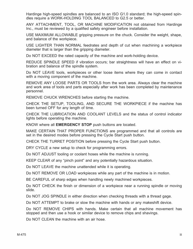
Hardinge high-speed spindles are balanced to an ISO G1.0 standard; the high-speed spin-dles require a WORK-HOLDING TOOL BALANCED to G2.5 or better.
ANY ATTACHMENT, TOOL, OR MACHINE MODIFICATION not obtained from HardingeInc., must be reviewed by a qualified safety engineer before installation.
USE MAXIMUM ALLOWABLE gripping pressure on the chuck. Consider the weight, shape,and balance of the workpiece.
USE LIGHTER THAN NORMAL feedrates and depth of cut when machining a workpiecediameter that is larger than the gripping diameter.
Do NOT EXCEED the rated capacity of the machine and work-holding device.
REDUCE SPINDLE SPEED if vibration occurs; bar straightness will have an effect on vi-bration and balance of the spindle system.
Do NOT LEAVE tools, workpieces or other loose items where they can come in contactwith a moving component of the machine.
REMOVE ANY LOOSE PARTS OR TOOLS from the work area. Always clear the machineand work area of tools and parts especially after work has been completed by maintenancepersonnel.
REMOVE CHUCK WRENCHES before starting the machine.
CHECK THE SETUP, TOOLING, AND SECURE THE WORKPIECE if the machine hasbeen turned OFF for any length of time.
CHECK THE LUBRICATION AND COOLANT LEVELS and the status of control indicatorlights before operating the machine.
KNOW where all EMERGENCY STOP push buttons are located.
MAKE CERTAIN THAT PROPER FUNCTIONS are programmed and that all controls areset in the desired modes before pressing the Cycle Start push button.
CHECK THE TURRET POSITION before pressing the Cycle Start push button.
DRY CYCLE a new setup to check for programming errors.
Do NOT ADJUST tooling or coolant hoses while the machine is running.
KEEP CLEAR of any “pinch point” and any potentially hazardous situation.
Do NOT LEAVE the machine unattended while it is operating.
Do NOT REMOVE OR LOAD workpieces while any part of the machine is in motion.
BE CAREFUL of sharp edges when handling newly machined workpieces.
Do NOT CHECK the finish or dimension of a workpiece near a running spindle or movingslide.
Do NOT JOG SPINDLE in either direction when checking threads with a thread gage.
Do NOT ATTEMPT to brake or slow the machine with hands or any makeshift device.
Do NOT REMOVE CHIPS with hands. Make certain that all machine movement hasstopped and then use a hook or similar device to remove chips and shavings.
Do NOT CLEAN the machine with an air hose.
M-475 iii

KEEP TOTE PANS a safe distance from machine. Don’t overfill the tote pans.
Do NOT LET STOCK project past the back end of the collet closer or machine spindlewithout being adequately contained and properly supported.
When a bar feed system is used, make certain that it is properly ALIGNED with the spin-dle. If the bar feed is a floor-mounted type, it must be securely fastened to floor.
When a bar feed system is used, follow the bar feed manufacturer’s guidelines. For perfor-mance and safe application - SIZE and USE feed tube bushings, pushers, and spindle lin-ers according to the bar feed manufacturer’s information.
During high-speed applications, the bar stock must be contained within the collet closerand a bar feed not be used. Hardinge recommends using a bar loader for high-speed ap-plications of feeding stock to the work-holding device. Bar loaders feed the entire bar stockinto the spindle and, then, the pusher is disengaged from the bar.
Unless otherwise noted, all operating and maintenance procedures are to be performed byone person. To avoid injury to yourself and others, be sure that all personnel are clear ofthe machine when opening or closing the coolant guard door and any access covers.
FOR YOUR PROTECTION - WORK SAFELY
iv M-475

Table of Contents
CHAPTER 1- MAIN SPINDLE ALIGNMENT
ACCESSING THE MAIN SPINDLE . . . . . . . . . . . . . . . . . . . . . . . . 1-1
ADJUSTING THE MAIN SPINDLE FOR PARALLEL . . . . . . . . . . . . . . . . 1-4
ADJUSTING MAIN SPINDLE CENTERLINE . . . . . . . . . . . . . . . . . . . . 1-8
CHAPTER 2- TAILSTOCK ALIGNMENT
INTRODUCTION . . . . . . . . . . . . . . . . . . . . . . . . . . . . . . . . 2-1
LIVE CENTER REMOVAL AND INSTALLATION . . . . . . . . . . . . . . . . . . 2-2
TAILSTOCK ALIGNMENT PROCEDURE . . . . . . . . . . . . . . . . . . . . . 2-3
CHAPTER 3- SUB-SPINDLE ALIGNMENT
ACCESSING THE SUB-SPINDLE . . . . . . . . . . . . . . . . . . . . . . . . 3-1
ADJUSTING THE SUB-SPINDLE FOR PARALLEL. . . . . . . . . . . . . . . . . 3-4
M-475 v

- NOTES -
vi M-475
CHAPTER 1- MAIN SPINDLE ALIGNMENT
ACCESSING THE MAIN SPINDLE
- WARNING -
The machine will be powered up during this procedure.
Be sure all personnel are clear of the machine when moving the machine axes.
- NOTE -
Refer to the operator's manual (M-392) for information on moving the machine axes.
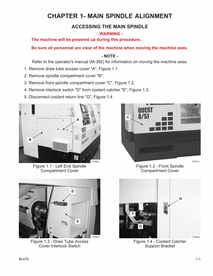
1. Remove draw tube access cover "A", Figure 1.1.
2. Remove spindle compartment cover "B".
3. Remove front spindle compartment cover "C", Figure 1.2.
4. Remove interlock switch "D" from coolant catcher "E", Figure 1.3.
5. Disconnect coolant return line "G", Figure 1.4.
M-475 1-1
Figure 1.1 - Left End SpindleCompartment Cover
TP5963
B
A
Figure 1.2 - Front SpindleCompartment Cover
C
TP4737
Figure 1.3 - Draw Tube AccessCover Interlock Switch
D
E
TP5957
Figure 1.4 - Coolant CatcherSupport Bracket
F
G
H
TP5964
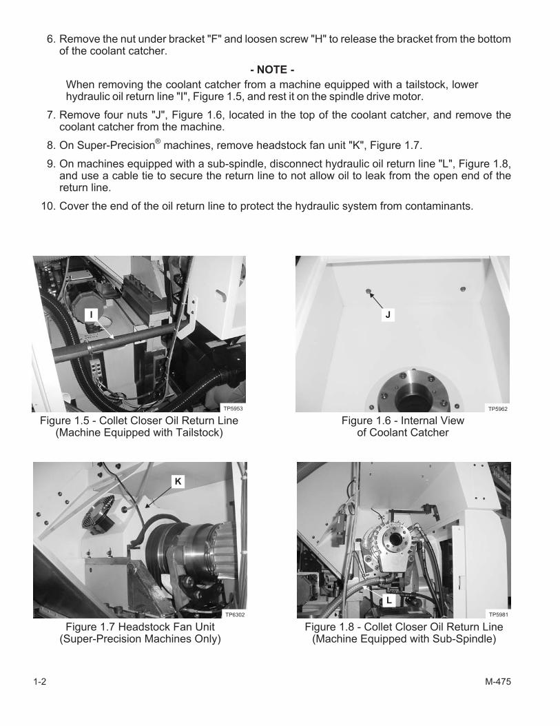
6. Remove the nut under bracket "F" and loosen screw "H" to release the bracket from the bottomof the coolant catcher.
- NOTE -
When removing the coolant catcher from a machine equipped with a tailstock, lowerhydraulic oil return line "I", Figure 1.5, and rest it on the spindle drive motor.
7. Remove four nuts "J", Figure 1.6, located in the top of the coolant catcher, and remove thecoolant catcher from the machine.
8. On Super-Precision®
machines, remove headstock fan unit "K", Figure 1.7.
9. On machines equipped with a sub-spindle, disconnect hydraulic oil return line "L", Figure 1.8,and use a cable tie to secure the return line to not allow oil to leak from the open end of thereturn line.
10. Cover the end of the oil return line to protect the hydraulic system from contaminants.
1-2 M-475
Figure 1.5 - Collet Closer Oil Return Line(Machine Equipped with Tailstock)
I
TP5953
Figure 1.6 - Internal Viewof Coolant Catcher
J
TP5962
Figure 1.7 Headstock Fan Unit(Super-Precision Machines Only)
K
TP6302
Figure 1.8 - Collet Closer Oil Return Line(Machine Equipped with Sub-Spindle)
L
TP5981
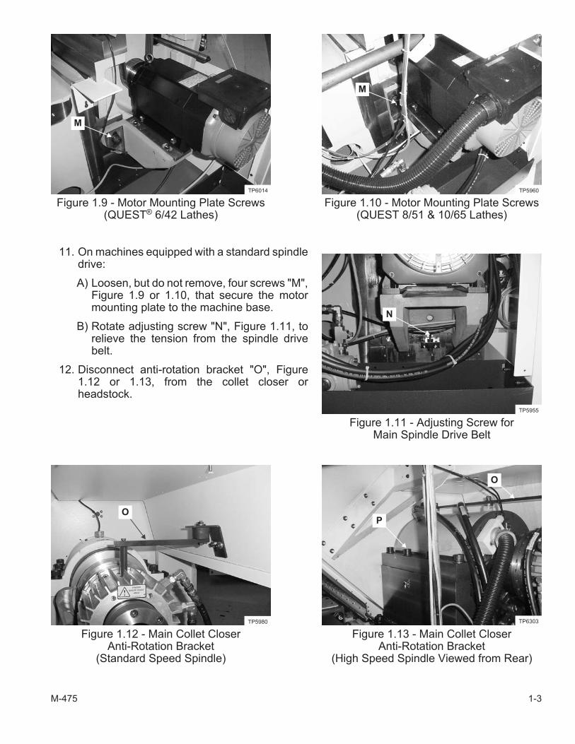
11. On machines equipped with a standard spindledrive:
A) Loosen, but do not remove, four screws "M",Figure 1.9 or 1.10, that secure the motormounting plate to the machine base.
B) Rotate adjusting screw "N", Figure 1.11, torelieve the tension from the spindle drivebelt.
12. Disconnect anti-rotation bracket "O", Figure1.12 or 1.13, from the collet closer orheadstock.
M-475 1-3
Figure 1.9 - Motor Mounting Plate Screws(QUEST® 6/42 Lathes)
M
TP6014
Figure 1.10 - Motor Mounting Plate Screws(QUEST 8/51 & 10/65 Lathes)
M
TP5960
Figure 1.11 - Adjusting Screw forMain Spindle Drive Belt
N
TP5955
Figure 1.12 - Main Collet CloserAnti-Rotation Bracket
(Standard Speed Spindle)
O
TP5980
Figure 1.13 - Main Collet CloserAnti-Rotation Bracket
(High Speed Spindle Viewed from Rear)
O
TP6303
P

ADJUSTING THE MAIN SPINDLE FOR PARALLEL
13. Move the turret to a safe index position.
14. Index the turret top plate to station #1.
15. Install the long head arbor in the main spindle.
- NOTE -
Hardinge Inc. recommends the use of an adjustable indicator slide to accuratelyposition the indicator against the head arbor.
16. Mount an adjustable indicator slide on the turret top plate at station #1. Refer to Figure 1.14.
17. Mount an indicator on the indicator slide.
18. Move the turret to position the indicator asshown in Figure 1.15.
19. Adjust the indicator slide to set the indicator tocontact the arbor on the same plane as aturning tool would contact a workpiece.
20. Manually rotate the arbor and check forrun-out.
21. If run-out is detected, split the run-out androtate the arbor until the split value isdisplayed.
22. Zero the indicator.
23. Slowly move the Z axis toward the spindle toindicate along the length of the alignmentarbor, as shown in Figure 1.16.
1-4 M-475
Figure 1.14 - Adjustable Indicator SlideMounted on the Turret Top Plate
(VDI 30 Top Plate Shown)
TP6330
Figure 1.15 - Indicator PositionBefore Sweeping the Arbor
TP6307
Figure 1.16 - Indicator PositionAfter Sweeping the Arbor
TP6308

- NOTE -
The spindle parallel specification for precision machines is ±.00015 inch [.0038 mm]total indicator run-out in 8 inches [203.2 mm] of travel on the Z axis.
The spindle parallel specification for Super-Precision® machines is ±.00012 inch[.0030 mm] total indicator run-out in 8 inches [203.2 mm] of travel on the Z axis.
24. If the spindle parallel is within specification, proceed to step 39.
If the spindle parallel is NOT within specification, proceed to step 25.
- NOTE -
Headstocks with a standard speed spindle are secured with six mounting screws.
Headstocks with a high speed spindle are secured with eight mounting screws.
25. Loosen headstock mounting screws "P", Figure 1.13 or 1.17.
- NOTE -
The alignment bracket mounting screws are each equipped with two washers toprovide clearance between alignment brackets "Q" and the main spindle headstockwhen an alignment is not being performed.
26. Remove the four screws to remove the washers behind alignment brackets "Q", Figure 1.17.
27. Install the alignment brackets without the washers with the upper screws only. The lowerscrews will be used to move the headstock during the alignment procedure.
28. Pull the headstock against the locating set screws in the alignment brackets.
29. Move the turret to position the indicator as shown in Figure 1.15.
30. Repeat steps 22 and 23 to check spindle parallel.
31. If the spindle parallel is within specification, proceed to step 39.
If the spindle parallel is NOT within specification, proceed to step 32.
32. Insert the remaining two alignment bracket screws through the clearance holes near the top ofthe alignment brackets and thread into the headstock.
M-475 1-5
Figure 1.17 - Headstock Mounting Screwsand Alignment Brackets
(Standard Spindle Viewed from the Front)
P
Q
TP6296
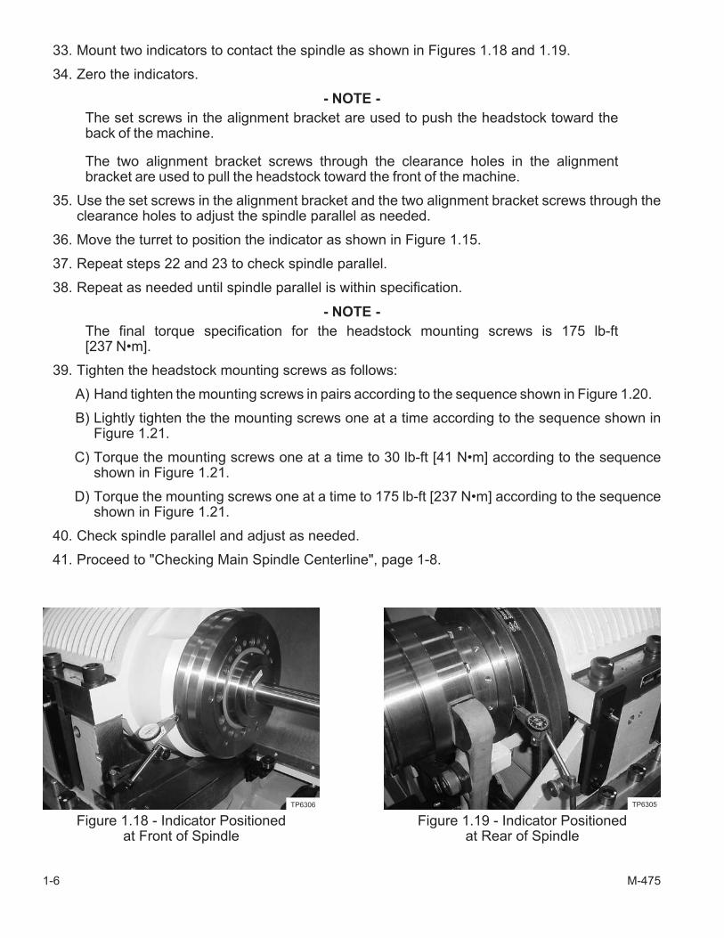
33. Mount two indicators to contact the spindle as shown in Figures 1.18 and 1.19.
34. Zero the indicators.
- NOTE -
The set screws in the alignment bracket are used to push the headstock toward theback of the machine.
The two alignment bracket screws through the clearance holes in the alignmentbracket are used to pull the headstock toward the front of the machine.
35. Use the set screws in the alignment bracket and the two alignment bracket screws through theclearance holes to adjust the spindle parallel as needed.
36. Move the turret to position the indicator as shown in Figure 1.15.
37. Repeat steps 22 and 23 to check spindle parallel.
38. Repeat as needed until spindle parallel is within specification.
- NOTE -
The final torque specification for the headstock mounting screws is 175 lb-ft[237 N•m].
39. Tighten the headstock mounting screws as follows:
A) Hand tighten the mounting screws in pairs according to the sequence shown in Figure 1.20.
B) Lightly tighten the the mounting screws one at a time according to the sequence shown inFigure 1.21.
C) Torque the mounting screws one at a time to 30 lb-ft [41 N•m] according to the sequenceshown in Figure 1.21.
D) Torque the mounting screws one at a time to 175 lb-ft [237 N•m] according to the sequenceshown in Figure 1.21.
40. Check spindle parallel and adjust as needed.
41. Proceed to "Checking Main Spindle Centerline", page 1-8.
1-6 M-475
Figure 1.18 - Indicator Positionedat Front of Spindle
TP6306
Figure 1.19 - Indicator Positionedat Rear of Spindle
TP6305

M-475 1-7
Figure 1.20 - Sequence for Hand Tighteningthe Main Spindle Headstock Mounting Screws
Standard Spindle High Speed Spindle
13 2 4
24 1 3
3 1 2
2 1 3
TI5146
HeadstockMounting Screws
Figure 1.21 - Sequence for Mechanically Tighteningthe Main Spindle Headstock Mounting Screws
Standard Spindle High Speed Spindle
15 3 8
47 2 6
3 2 5
6 1 4
TI5146
HeadstockMounting Screws
ADJUSTING MAIN SPINDLE CENTERLINE
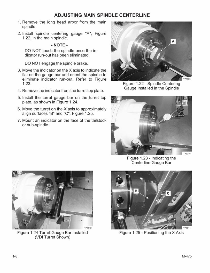
1. Remove the long head arbor from the mainspindle.
2. Install spindle centering gauge "A", Figure1.22, in the main spindle.
- NOTE -
DO NOT touch the spindle once the in-dicator run-out has been eliminated.
DO NOT engage the spindle brake.
3. Move the indicator on the X axis to indicate theflat on the gauge bar and orient the spindle toeliminate indicator run-out. Refer to Figure1.23.
4. Remove the indicator from the turret top plate.
5. Install the turret gauge bar on the turret topplate, as shown in Figure 1.24.
6. Move the turret on the X axis to approximatelyalign surfaces "B" and "C", Figure 1.25.
7. Mount an indicator on the face of the tailstockor sub-spindle.
1-8 M-475
Figure 1.22 - Spindle CenteringGauge Installed in the Spindle
A
TP6309
Figure 1.23 - Indicating theCenterline Gauge Bar
TP6310
Figure 1.24 Turret Gauge Bar Installed(VDI Turret Shown)
TP6312
Figure 1.25 - Positioning the X Axis
BC
TP6311
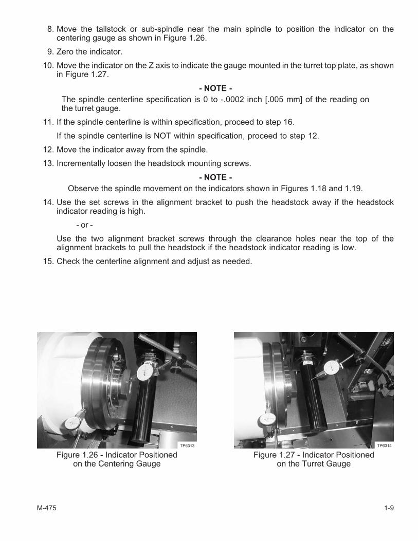
8. Move the tailstock or sub-spindle near the main spindle to position the indicator on thecentering gauge as shown in Figure 1.26.
9. Zero the indicator.
10. Move the indicator on the Z axis to indicate the gauge mounted in the turret top plate, as shownin Figure 1.27.
- NOTE -
The spindle centerline specification is 0 to -.0002 inch [.005 mm] of the reading onthe turret gauge.
11. If the spindle centerline is within specification, proceed to step 16.
If the spindle centerline is NOT within specification, proceed to step 12.
12. Move the indicator away from the spindle.
13. Incrementally loosen the headstock mounting screws.
- NOTE -
Observe the spindle movement on the indicators shown in Figures 1.18 and 1.19.
14. Use the set screws in the alignment bracket to push the headstock away if the headstockindicator reading is high.
- or -
Use the two alignment bracket screws through the clearance holes near the top of thealignment brackets to pull the headstock if the headstock indicator reading is low.
15. Check the centerline alignment and adjust as needed.
M-475 1-9
Figure 1.26 - Indicator Positionedon the Centering Gauge
TP6313
Figure 1.27 - Indicator Positionedon the Turret Gauge
TP6314
16. Tighten the the headstock mounting screws as outlined in step 39, page 1-6.
17. Repeat the parallel and centerline checks to be sure the spindle meets both specifications.
18. Remove the indicator, indicator slide, and gauging from the machine.
19. Remove the alignment brackets from the headstock.
20. Install the washers removed during the parallel adjustment and mount the alignment bracketson the headstock using the four mounting screws.
- NOTE -
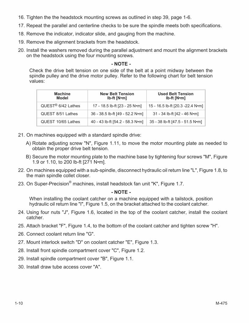
Check the drive belt tension on one side of the belt at a point midway between thespindle pulley and the drive motor pulley. Refer to the following chart for belt tensionvalues:
MachineModel
New Belt Tensionlb-ft [N•m]
Used Belt Tensionlb-ft [N•m]
QUEST® 6/42 Lathes 17 - 18.5 lb-ft [23 - 25 N•m] 15 - 16.5 lb-ft [20.3 -22.4 N•m]
QUEST 8/51 Lathes 36 - 38.5 lb-ft [49 - 52.2 N•m] 31 - 34 lb-ft [42 - 46 N•m]
QUEST 10/65 Lathes 40 - 43 lb-ft [54.2 - 58.3 N•m] 35 - 38 lb-ft [47.5 - 51.5 N•m]
21. On machines equipped with a standard spindle drive:
A) Rotate adjusting screw "N", Figure 1.11, to move the motor mounting plate as needed toobtain the proper drive belt tension.
B) Secure the motor mounting plate to the machine base by tightening four screws "M", Figure1.9 or 1.10, to 200 lb-ft [271 N•m].
22. On machines equipped with a sub-spindle, disconnect hydraulic oil return line "L", Figure 1.8, tothe main spindle collet closer.
23. On Super-Precision®
machines, install headstock fan unit "K", Figure 1.7.
- NOTE -
When installing the coolant catcher on a machine equipped with a tailstock, positionhydraulic oil return line "I", Figure 1.5, on the bracket attached to the coolant catcher.
24. Using four nuts "J", Figure 1.6, located in the top of the coolant catcher, install the coolantcatcher.
25. Attach bracket "F", Figure 1.4, to the bottom of the coolant catcher and tighten screw "H".
26. Connect coolant return line "G".
27. Mount interlock switch "D" on coolant catcher "E", Figure 1.3.
28. Install front spindle compartment cover "C", Figure 1.2.
29. Install spindle compartment cover "B", Figure 1.1.
30. Install draw tube access cover "A".
1-10 M-475

- NOTES -
M-475 1-11

- NOTES -
1-12 M-475
CHAPTER 2- TAILSTOCK ALIGNMENT
INTRODUCTION
- WARNING -
The machine will be powered up during this procedure.
Be sure all personnel are clear of the machine when moving the machine axes.
DO NOT program tailstock motion until the tailstock alignment has been com-pleted.
The tailstock design incorporates a safety shear feature to limit the damage if there is contact be-tween the tailstock and the turret or its tooling. If contact is made, the safety shear feature allows thetailstock body to pivot on the tailstock base. Refer to page 2-3 for instructions on re-aligning thetailstock.
An alignment block is used to pivot the tailstock back into alignment. Contact the Hardinge SalesDepartment to purchase the appropriate alignment kit, based on the machine model.
The tailstock on a QUEST® 6/42 lathe is equipped with a bushing that will accept a live center with a#3 Morse taper.
The tailstock on a QUEST 8/51 or 10/65 lathe is equipped with a bushing that will accept a live cen-ter with a #4 Morse taper.
- CAUTION -
Always make certain that the turret is in a safe index position before moving thetailstock toward the spindle.
- NOTE -
The tailstock hydraulic pressure is set at 450 psi [31 bar] for the alignmentprocedure. Refer to the operator's manual (M-392) for information on setting thetailstock hydraulic pressure.
M-475 2-1
LIVE CENTER REMOVAL AND INSTALLATION
- NOTE -
Refer to the operator's manual (M-392) for information on moving the machine axes.
1. Move the turret to the X and Z axis reference positions.
2. Move the tailstock to a convenient work space in front of the main access door.
3. Power down the machine.
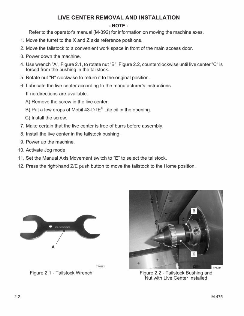
4. Use wrench "A", Figure 2.1, to rotate nut "B", Figure 2.2, counterclockwise until live center "C" isforced from the bushing in the tailstock.
5. Rotate nut "B" clockwise to return it to the original position.
6. Lubricate the live center according to the manufacturer’s instructions.
If no directions are available:
A) Remove the screw in the live center.
B) Put a few drops of Mobil 43-DTE®
Lite oil in the opening.
C) Install the screw.
7. Make certain that the live center is free of burrs before assembly.
8. Install the live center in the tailstock bushing.
9. Power up the machine.
10. Activate Jog mode.
11. Set the Manual Axis Movement switch to “E” to select the tailstock.
12. Press the right-hand Z/E push button to move the tailstock to the Home position.
2-2 M-475
Figure 2.1 - Tailstock Wrench
TP6282
A
Figure 2.2 - Tailstock Bushing andNut with Live Center Installed
TP6284
B
C
TAILSTOCK ALIGNMENT PROCEDURE
- WARNING -
DO NOT program tailstock motion until the tailstock alignment has been com-pleted.
- NOTE -
Refer to the operator's manual (M-392) for information on moving the machine axes.
1. Jog the turret and turret tooling clear of thetailstock.
2. Remove the workpiece.
3. Power down the machine.
4. Open the main coolant guard door.
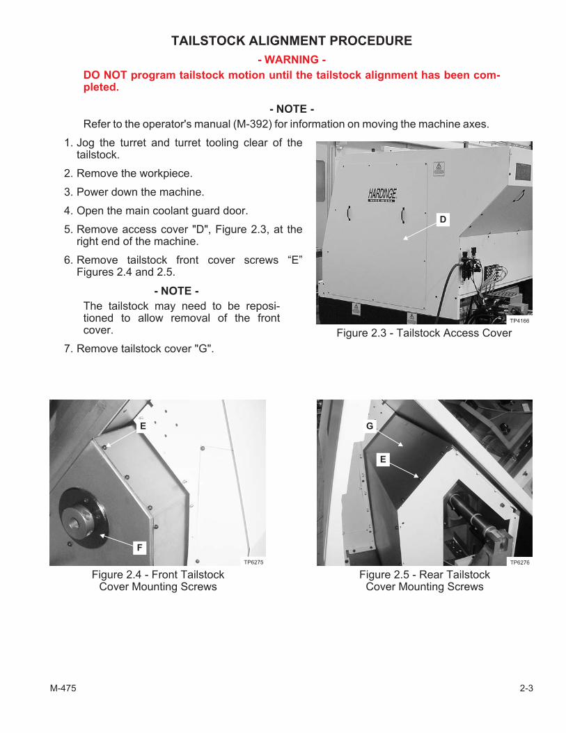
5. Remove access cover "D", Figure 2.3, at theright end of the machine.
6. Remove tailstock front cover screws “E”Figures 2.4 and 2.5.
- NOTE -
The tailstock may need to be reposi-tioned to allow removal of the frontcover.
7. Remove tailstock cover "G".
M-475 2-3
Figure 2.3 - Tailstock Access Cover
D
TP4166
Figure 2.4 - Front TailstockCover Mounting Screws
TP6275
E
F
Figure 2.5 - Rear TailstockCover Mounting Screws
E
TP6276
G
8. Remove the center from the tailstock as outlined on page 2-2.
9. Remove tailstock cap "F", Figure 2.4, and associated O-ring.
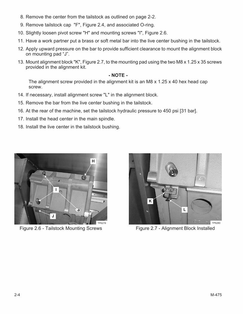
10. Slightly loosen pivot screw "H" and mounting screws "I", Figure 2.6.
11. Have a work partner put a brass or soft metal bar into the live center bushing in the tailstock.
12. Apply upward pressure on the bar to provide sufficient clearance to mount the alignment blockon mounting pad “J”.
13. Mount alignment block "K", Figure 2.7, to the mounting pad using the two M8 x 1.25 x 35 screwsprovided in the alignment kit.
- NOTE -
The alignment screw provided in the alignment kit is an M8 x 1.25 x 40 hex head capscrew.
14. If necessary, install alignment screw "L" in the alignment block.
15. Remove the bar from the live center bushing in the tailstock.
16. At the rear of the machine, set the tailstock hydraulic pressure to 450 psi [31 bar].
17. Install the head center in the main spindle.
18. Install the live center in the tailstock bushing.
2-4 M-475
Figure 2.6 - Tailstock Mounting Screws
TP6278
H
I
J
Figure 2.7 - Alignment Block Installed
K
TP6280
L
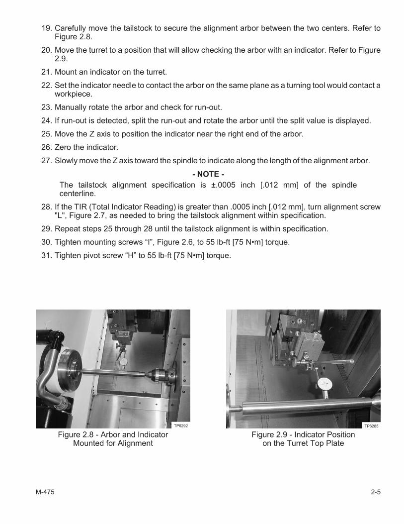
19. Carefully move the tailstock to secure the alignment arbor between the two centers. Refer toFigure 2.8.
20. Move the turret to a position that will allow checking the arbor with an indicator. Refer to Figure2.9.
21. Mount an indicator on the turret.
22. Set the indicator needle to contact the arbor on the same plane as a turning tool would contact aworkpiece.
23. Manually rotate the arbor and check for run-out.
24. If run-out is detected, split the run-out and rotate the arbor until the split value is displayed.
25. Move the Z axis to position the indicator near the right end of the arbor.
26. Zero the indicator.
27. Slowly move the Z axis toward the spindle to indicate along the length of the alignment arbor.
- NOTE -
The tailstock alignment specification is ±.0005 inch [.012 mm] of the spindlecenterline.
28. If the TIR (Total Indicator Reading) is greater than .0005 inch [.012 mm], turn alignment screw"L", Figure 2.7, as needed to bring the tailstock alignment within specification.
29. Repeat steps 25 through 28 until the tailstock alignment is within specification.
30. Tighten mounting screws “I”, Figure 2.6, to 55 lb-ft [75 N•m] torque.
31. Tighten pivot screw “H” to 55 lb-ft [75 N•m] torque.
M-475 2-5
Figure 2.8 - Arbor and IndicatorMounted for Alignment
TP6292
Figure 2.9 - Indicator Positionon the Turret Top Plate
TP6285

32. Move the turret and indicator away from the arbor.
33. Hold the arbor and move the tailstock to the Home position.
34. Recheck the tailstock alignment:
A) Move the tailstock toward the spindle to secure the arbor between the two centers.
B) Position the indicator at the right end of the arbor as previously described.
C) Slowly move the Z axis toward the spindle to indicate along the length of the alignment arbor.
D) If the indicator reading is within specification, proceed to step 35.
If the indicator reading is NOT within specification, adjust as needed.
35. Remove alignment block "K", Figure 2.7.
36. Apply silicone grease to the mounting frame for tailstock front cover "G", Figure 2.5.
- NOTE -
The tailstock may need to be repositioned to allow installation of the front cover.
37. Install tailstock front cover "G".
38. Install screws "E", Figures 2.4 and 2.5.
39. Remove the arbor while moving the tailstock to the Home position.
40. Install tailstock cap "F", Figure 2.4, and associated O-ring.
41. Remove the head center from the spindle.
42. Replace access cover "D", Figure 2.3, at the right end of the machine.
43. Close the main coolant guard door.
2-6 M-475

- NOTES -
M-475 2-7

- NOTES -
2-8 M-475
CHAPTER 3- SUB-SPINDLE ALIGNMENT
- WARNING -
The machine will be powered up during this procedure.
Be sure all personnel are clear of the machine when moving the machine axes.
- NOTE -
Refer to the operator's manual (M-392) for information on moving the machine axes.
This procedure requires the use of a sonic belt tension meter.
ACCESSING THE SUB-SPINDLE
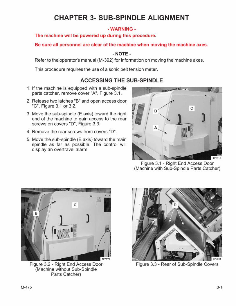
1. If the machine is equipped with a sub-spindleparts catcher, remove cover "A", Figure 3.1.
2. Release two latches "B" and open access door"C", Figure 3.1 or 3.2.
3. Move the sub-spindle (E axis) toward the rightend of the machine to gain access to the rearscrews on covers "D", Figure 3.3.
4. Remove the rear screws from covers "D".
5. Move the sub-spindle (E axis) toward the mainspindle as far as possible. The control willdisplay an overtravel alarm.
M-475 3-1
Figure 3.1 - Right End Access Door(Machine with Sub-Spindle Parts Catcher)
A
BC
TP6015
Figure 3.2 - Right End Access Door(Machine without Sub-Spindle
Parts Catcher)
B
C
TP5779
Figure 3.3 - Rear of Sub-Spindle Covers
D
TP6001

6. Remove the front screws from covers "D", Figure 3.4.
- NOTE -
It is recommended to place a shop cloth on the machine where cable carrier bracket"E", Figure 3.5, will rest after the screws are removed.
7. At the right end of the machine, remove the screws from cable carrier bracket "E", Figure 3.5, toallow cable carrier "F", Figure 3.6, to be lowered to provide clearance for removing thesub-spindle covers.
8. Slide covers "D", Figure 3.3, out the end of the machine.
3-2 M-475
Figure 3.4 - Front of Sub-Spindle Covers
D
TP6004
Figure 3.5 - Bracket forSub-Spindle Cable Carrier
E
TP6000
Figure 3.6 - Sub-Spindle Cable Carrier
F
TP5999
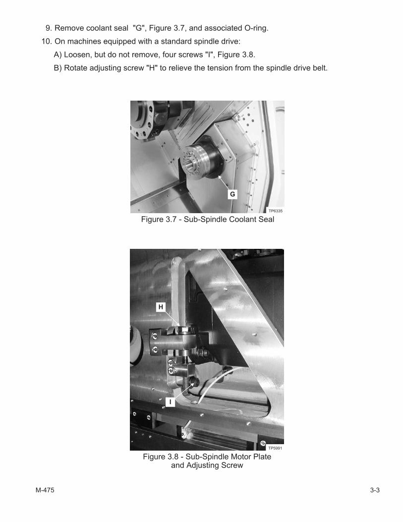
9. Remove coolant seal "G", Figure 3.7, and associated O-ring.
10. On machines equipped with a standard spindle drive:
A) Loosen, but do not remove, four screws "I", Figure 3.8.
B) Rotate adjusting screw "H" to relieve the tension from the spindle drive belt.
M-475 3-3
Figure 3.7 - Sub-Spindle Coolant Seal
G
TP6335
Figure 3.8 - Sub-Spindle Motor Plateand Adjusting Screw
H
I
TP5991
ADJUSTING THE SUB-SPINDLE FOR PARALLEL
11. Move the sub-spindle away from the main spindle to allow the installation of a short head arborin the main spindle and sub-spindle.
- NOTE -
Hardinge Inc. recommends the use of an adjustable indicator slide to accuratelyposition the indicator against the head arbors.
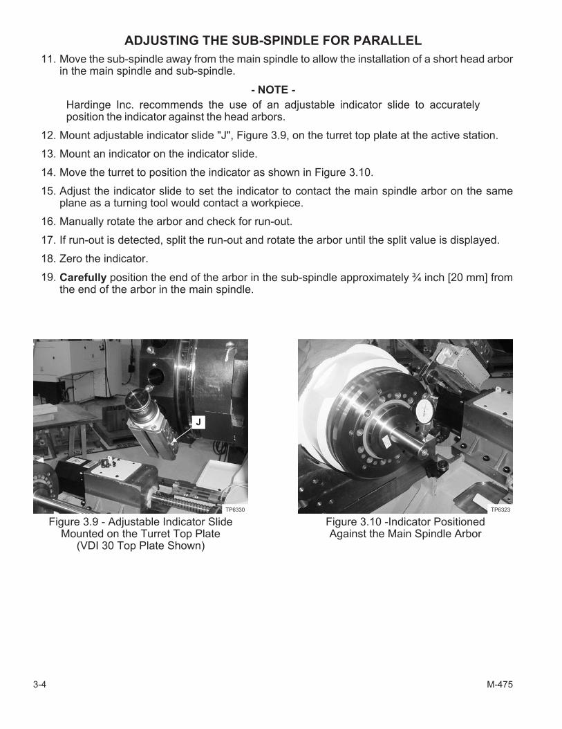
12. Mount adjustable indicator slide "J", Figure 3.9, on the turret top plate at the active station.
13. Mount an indicator on the indicator slide.
14. Move the turret to position the indicator as shown in Figure 3.10.
15. Adjust the indicator slide to set the indicator to contact the main spindle arbor on the sameplane as a turning tool would contact a workpiece.
16. Manually rotate the arbor and check for run-out.
17. If run-out is detected, split the run-out and rotate the arbor until the split value is displayed.
18. Zero the indicator.
19. Carefully position the end of the arbor in the sub-spindle approximately ¾ inch [20 mm] fromthe end of the arbor in the main spindle.
3-4 M-475
Figure 3.9 - Adjustable Indicator SlideMounted on the Turret Top Plate
(VDI 30 Top Plate Shown)
J
TP6330
Figure 3.10 -Indicator PositionedAgainst the Main Spindle Arbor
TP6323

20. Move the Z axis to position the indicator against the diameter of the arbor in the sub-spindle.Refer to Figure 3.11.
- NOTE -
The sub-spindle must be parallel with the main spindle within .0005 inch [.012 mm].
21. Observe the indicator reading.
22. Slowly move the Z axis toward the face of the sub-spindle to indicate along the length of thealignment arbor. Refer to Figure 3.12.
23. Observe the indicator reading to check the sub-spindle parallel.
- NOTE -
Headstocks with a standard speed spindle are secured with six mounting screws.
Headstocks with a high speed spindle are secured with eight mounting screws.
24. Loosen sub-spindle headstock mountingscrews "K", Figure 3.13.
- NOTE -
The alignment bracket mounting screwsare each equipped with two washers toprovide clearance between alignmentbrackets "L" and the sub-spindleheadstock when an alignment is not be-ing performed.
25. Remove the four screws to remove thewashers behind alignment brackets "L", Figure3.13.
M-475 3-5
Figure 3.11 - Indicator Position BeforeSweeping the Short Sub-Spindle Arbor
TP6324
Figure 3.12 - Indicator Position AfterSweeping the Short Sub-Spindle Arbor
TP6325
Figure 3.13 - Sub-Spindle MountingScrews and Alignment Brackets
(Standard Speed Spindle Shown)
L
TP6301
K
26. Install the alignment brackets without the washers.
27. Pull the sub-spindle headstock against the locating set screws in the alignment brackets.
28. Repeat steps 20 through 23 to check sub-spindle alignment.
29. If the sub-spindle parallel is within specification, proceed to step 34.
If the sub-spindle parallel is NOT within specification, proceed to step 30.
30. Insert two M10 x 1.5 x 35 mm socket head cap screws through the clearance holes near the topof the alignment brackets and thread into the headstock.
- NOTE -
The set screws in the alignment bracket are used to push the headstock toward theback of the machine.
The two screws through the clearance holes in the alignment bracket are used topull the headstock toward the front of the machine.
31. Use the set screws in the alignment bracket and the two screws through the clearance holes toadjust the spindle parallel as needed.
32. Repeat steps 20 through 23 to check sub-spindle alignment.
33. Repeat as needed until sub-spindle parallel is within specification.
- NOTE -
The final torque specification for the sub-spindle headstock mounting screws is 150lb-ft [203 N•m].
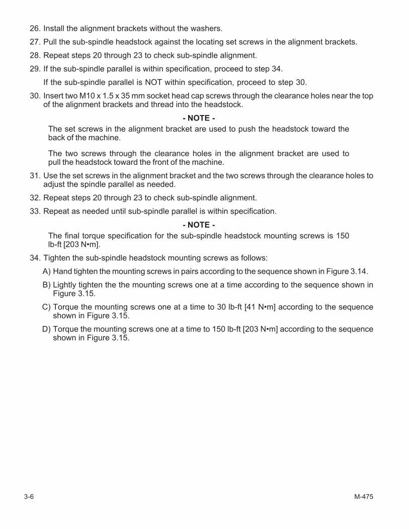
34. Tighten the sub-spindle headstock mounting screws as follows:
A) Hand tighten the mounting screws in pairs according to the sequence shown in Figure 3.14.
B) Lightly tighten the the mounting screws one at a time according to the sequence shown inFigure 3.15.
C) Torque the mounting screws one at a time to 30 lb-ft [41 N•m] according to the sequenceshown in Figure 3.15.
D) Torque the mounting screws one at a time to 150 lb-ft [203 N•m] according to the sequenceshown in Figure 3.15.
3-6 M-475
M-475 3-7
Figure 3.14 - Sequence for Hand Tighteningthe Sub-Spindle Headstock Mounting Screws
Standard Spindle High Speed Spindle
13 2 4
24 1 3
3 1 2
2 1 3
TI5147
HeadstockMounting Screws
Figure 3.15 - Sequence for Mechanically Tighteningthe Sub-Spindle Headstock Mounting Screws
Standard Spindle High Speed Spindle
17 3 5
46 2 8
6 1 3
4 2 5
TI5147
HeadstockMounting Screws
35. Check spindle parallel and adjust as needed.
36. Move the sub-spindle away from the main spindle.
37. Install the long head arbor in the sub-spindle.
38. Move the sub-spindle to the Reference (Home) position.
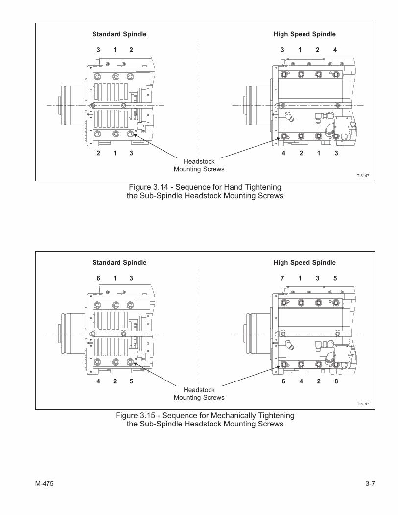
39. Move the Z axis to position the indicator against the diameter of the arbor in the sub-spindle,Refer to Figure 3.16.
40. Zero the indicator.
- NOTE -
The sub-spindle parallel specification at the Reference position is ±.0003 inch[.007 mm] total indicator run-out in 6 inches [152.4 mm] of travel on the Z axis.
41. Slowly move the Z axis toward the face of the sub-spindle to indicate along the length of thealignment arbor and observe the total indicator run-out. Refer to Figure 3.17.
42. If the sub-spindle parallel is within specification, proceed to step 43.
If the sub-spindle parallel is NOT within specification, repeat the necessary alignmentsteps, beginning with step 11.
43. Remove the indicator, indicator slide, and gauging from the machine.
44. Remove the alignment brackets from the headstock.
45. Install the washers removed during the parallel adjustment and mount the alignment bracketson the headstock using the four mounting screws.
46. Install coolant seal "G", Figure 3.7, and associated O-ring.
47. Move the sub-spindle (E axis) toward the main spindle as far as possible.
3-8 M-475
Figure 3.16 - Indicator Position BeforeSweeping the Long Sub-Spindle Arbor
TP6332
Figure 3.17 - Indicator Position AfterSweeping the Long Sub-Spindle Arbor
TP6333
- NOTE -
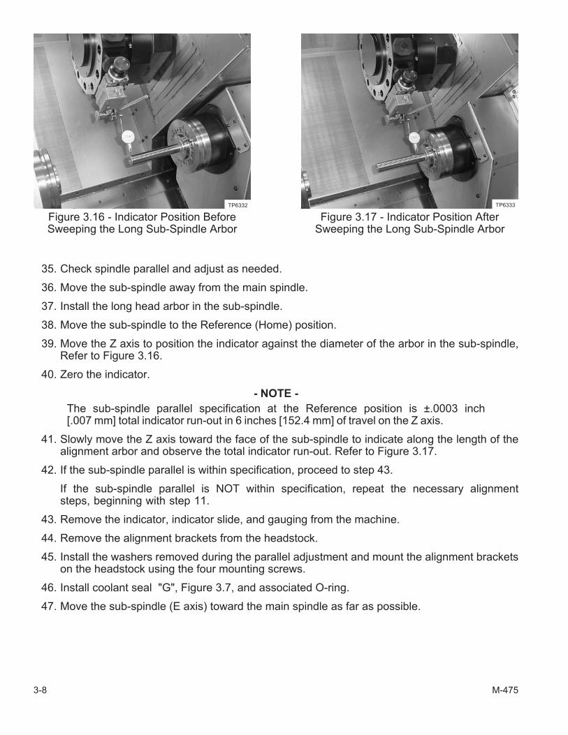
Access to the sub-spindle drive belt is through opening "M", Figure 3.18.
Belt tension is checked with a sonic belt tension meter.
48. On machines equipped with a standard sub-spindle drive:
A) Rotate adjusting screw "H", Figure 3.8, to move the motor mounting plate as needed toobtain the proper drive belt tension. Proper belt tension is as follows:
Force: 813 to 871 NewtonsFrequency: 195 to 202 HertzMass: .470 grams/cm2
Belt Width: 12 millimetersBelt Span: 308 millimeters
B) Tighten four screws "I" to 85 lb-ft [115 N•m].
49. Apply a continuous bead of silicone grease to all edges of sub-spindle front cover "N", Figure3.19, used to mount covers "D", Figure 3.4.
50. Replace covers "D", Figure 3.4.
51. Replace the front screws in covers "D".
52. Lift cable carrier "F", Figure 3.6, back into position and secure cable carrier bracket "E", Figure3.5, in position.
53. Move the sub-spindle to the Reference (Home) position.
54. Replace the rear screws in covers "D", Figure 3.3.
55. Close access door "C", Figure 3.1 or 3.2, and secure the latches.
56. If the machine is equipped with a sub-spindle parts catcher, replace cover "A", Figure 3.1.
M-475 3-9
Figure 3.18 - Drive Belt Access
M
TP5986
Figure 3.19 - Sub-Spindle Front Cover
N
TP6334

- NOTES -
3-10 M-475

- NOTES -
M-475 3-11

Hardinge Inc.Elmira, New York 14902-1507 USA
Phone: 607-734-2281 FAX: 607-734-8819www.hardinge.com