Embed Size (px)
Citation preview
Quenching of Aluminum AlloysD. Scott MacKenzie, Houghton InternationalNiels Bogh, Bogh IndustriesTom Croucher, Tom Croucher and Associates
QUENCHING refers to the rapid cooling ofmetal from the solution treating temperature,typically between 465 and 565 �C (870 and1050 �F) for aluminum alloys. The fundamentalobjective of quenching is to preserve, as nearlyas possible, a metastable solid solution formedat the solution heat treating temperature, byrapidly cooling to some lower temperature, usu-ally near room temperature. When quenchingrates from the solution temperature are suffi-ciently rapid to retain a solid solution, soluteatoms are available to form zones of homoge-neous (coherent or semicoherent) precipitationfor strengthening by age hardening at roomtemperature or moderately elevated tempera-tures. In addition, another purpose of quenchingis to maintain a certain minimum number ofvacant lattice sites to assist in promoting thelow-temperature diffusion during the agingstage of precipitation hardening.Precipitation during quenching can lead to
localized overaging, a loss of grain-boundarycorrosion resistance, and, in extreme cases,poor response during the age hardening treat-ment. When quenching rates from the solutiontemperature are not sufficiently rapid, the soluteatoms that diffuse to grain boundaries, as wellas the vacancies that migrate (with extremerapidity) to disordered regions, are irretrievablylost for practical purposes and fail to contributeto the process of age hardening.The highest attainable strengths from aging
hardening are generally associated with themost rapid quenching rates. Nonetheless, amaximum quenching rate is not necessarily aone-sided argument, because both distortionand residual stresses also develop with anincrease in the rate of cooling. A balance mustbe obtained between the need to quench suffi-ciently fast to retain most of the hardeningelements and compounds in solution and theneed to minimize residual stress and distortionin the parts being quenched. Obtaining proper-ties and low distortion is usually a balancingact. Often, optimal properties are obtained atthe expense of high residual stresses or highdistortion. Low distortion or residual stressesare usually obtained at a sacrifice in properties.
Therefore, the optimum rate of cooling is onewhere properties are just met, so that distortionis reduced.Aluminum also is extremely prone to distor-
tion due to both solution heat treatment andquenching. The coefficient of linear expansionof aluminum is twice that of steel (2.38 �10�5 mm/mm � �C for aluminum versus 1.12 �10�5 mm/mm � �C for steel), and large thermalstrains can develop within and across the sur-face of parts due to thermal expansion duringsolution heat treatment. In addition, tempera-tures during solution treatment approach theliquidus temperature and result in low strengthand high plasticity.The most troublesome changes in dimensions
and shape can occur during quenching, due tothe extent of nonuniform cooling, particularlyin thin sections of parts that contain variationsin thickness. If distortion is to be minimized,the temperature differences between differentareas of a part must be minimized consistentwith cooling all regions of the part sufficientlyfast to avoid excessive precipitation duringquenching. Aluminum alloys have a relativelyhigh thermal conductivity, between 1.4 and2.38 W/cm �K (975 and 1650 Btu � in./h � ft2 � �F),compared to a conductivity of approximately0.14 to 0.29 W/cm �K (100 to 200 Btu � in./h �ft2 � �F) for austenite in most carbon and low-alloy steels. The high conductivity of aluminumcan be both a benefit and a problem. If heat isbeing rapidly extracted at the part surface bythe quenchant, the high conductivity results inrapid temperature losses in thin sections andlarge temperature differences between thickand thin sections. If heat is being extractedmore slowly, the high metal conductivity aidsin maintaining temperature uniformity withinthe part.This article provides an overview on the fac-
tors used to determine a suitable cooling rateand the appropriate quenching process todevelop a suitable cooling rate. The practicaldifficulty lies in establishing just how fast a partof a particular alloy must be quenched, whilealso minimizing, as much as possible, thermalgradients within the part that may cause plastic
deformation and residual stress. To retain a suf-ficient amount of alloying elements in solidsolution for subsequent age hardening, it is nec-essary to determine a suitable cooling rate for agiven alloy and part by considering the follow-ing questions (Ref 1):
� Are there some temperatures during thequench when diffusion-controlled reactionswill occur faster?
� What is the critical quench rate for how fastthe part must be quenched to effectivelyretard diffusion of solute atoms in the solidsolution?
� What happens when cooling rates during aquench are slower than the critical quenchrate?
When a suitable cooling rate is determined, theappropriate quench process is determined byseveral operational factors, such as:
� The heat-extracting potential of the quench-ing fluid in the quiescent state at normalfluid temperatures and pressures (standardconditions)
� Changes in the heat-extracting potential ofthe fluid brought about by nonstandard con-ditions of agitation, temperature, or pressure
� Product thickness and internal conditions ofthe part that affect heat flow to the surface
� Surface and other external conditions thataffect the removal of heat
Many different methods and quench mediahave been used in quenching aluminum alloys,depending on the alloy and product thicknessand configuration. Hot or cold water and poly-alkylene glycol (PAG) quenchants are usedalmost exclusively in the quenching of alumi-num alloys. Water is the fluid most frequentlyemployed for quenching aluminum, but thereare a variety of quenchants and methods thathave been used (Ref 1):
� Cold water immersion� Hot water immersion� Boiling water� Water spray
ASM Handbook, Volume 4E, Heat Treating of Nonferrous AlloysG.E. Totten and D.S. MacKenzie, editors
Copyright # 2016 ASM InternationalW
All rights reservedwww.asminternational.org
� Polyalkylene glycol solutions� Air blast� Still air� Liquid nitrogen� Fast quenching oils� Brine solutions
Hot or cold water and PAG quenchants are usedalmost exclusively in the quenching of alumi-num alloys, and these quenchants are discussedin separate sections of this article. Water is thefluid most frequently employed for quenchingaluminum, and highly agitated cold water is anexcellent quenchant in terms of obtaining highcooling rates. However, quenching in cold watercan produce large differences in temperaturebetween thick and thin sections, resulting in loca-lized plastic flow and distortion observed afterquenching or during machining. Usually, distor-tion is controlled in aluminum parts by addingpolymers to water quenchants to reduce the con-vective or film coefficient between the part andthe water, as discussed further in this article.
Quench Sensitivity of Alloys
The most important metallurgical factor affect-ing the properties of age-hardenable aluminumalloys is solute loss, referring to the solutes thatare chemically bonded with other elements andthus unavailable for precipitation hardening.There are several factors that can lead to soluteloss and loss of properties. The rate of cooling inthe part during quenching is one key factor, butsolute loss also is affected bymetallurgical factorssuch as the type of dispersoids in an alloy, solvustemperatures, and casting homogenization tem-peratures (see the article “Metallurgy of HeatTreatable Aluminum Alloys” in this Volume).During quenching, the objective is to prevent
the precipitation of solutes during the coolingof high-temperature solid solution. If apprecia-ble precipitation during cooling is to beavoided, two requirements must be satisfied.First, the time required for transfer of the loadfrom the furnace to the quenching mediummust be short enough to preclude slow precool-ing into the temperature range where very rapidprecipitation takes place. The second require-ment for avoidance of appreciable precipitationduring quenching is that the volume, heat-absorption capacity, and rate of flow of thequenching medium be such that little or no pre-cipitation occurs during cooling. Any interrup-tion of the quench that may allow reheatinginto a temperature range where rapid precipita-tion can occur must be prohibited.The rate of precipitation, as a function of
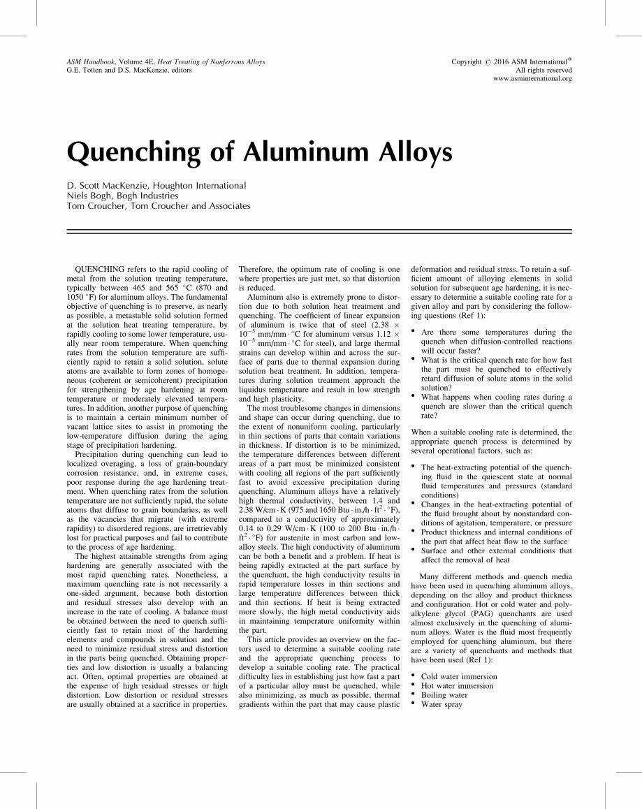
temperature, depends on two factors: the degreeof supersaturation and the rate of diffusion(Fig. 1). Diffusion rates increase at higher tem-peratures, but the nucleation rate of precipitatesis low because the degree of supersaturation islow at higher temperatures. Conversely, theprecipitation rate also is low at low tempera-tures, where the degree of supersaturation ishigh but with low rates of diffusion. At inter-mediate temperatures, the precipitation rate ishighest. Consequently, times to produce equal
amounts of precipitation follow a C-shaped pat-tern (Fig.1).Using isothermal quenching techniques, Fink
and Willey pioneered the attempts to describethe effects of quench rates with the use ofC-curves (Ref 2). Using isothermal quenchingtechniques, they developed C-curves forstrength of 7075-T6 and corrosion behavior of2024-T4. The C-curves were plots of the timerequired at different temperatures to precipitatea sufficient amount of solute to either reducestrength (Fig. 2a), cause a change in the corro-sion behavior (Fig. 2b), or relate to other prop-erties, such as electrical conductivity, fracturetoughness, or isothermal quench conditions.The nose of the C-curves identifies the regionof highest precipitation rates, which Fink andWilley called the critical temperature range.For alloy 7075 (Fig. 2a), this range was deter-mined to be 400 to 290 �C (750 to 550 �F).Investigators have used isothermal time-
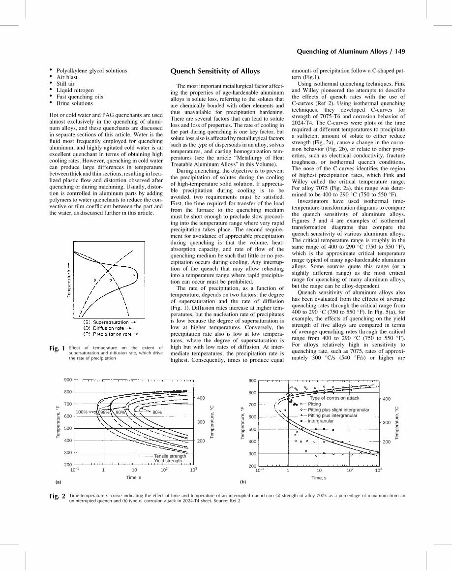
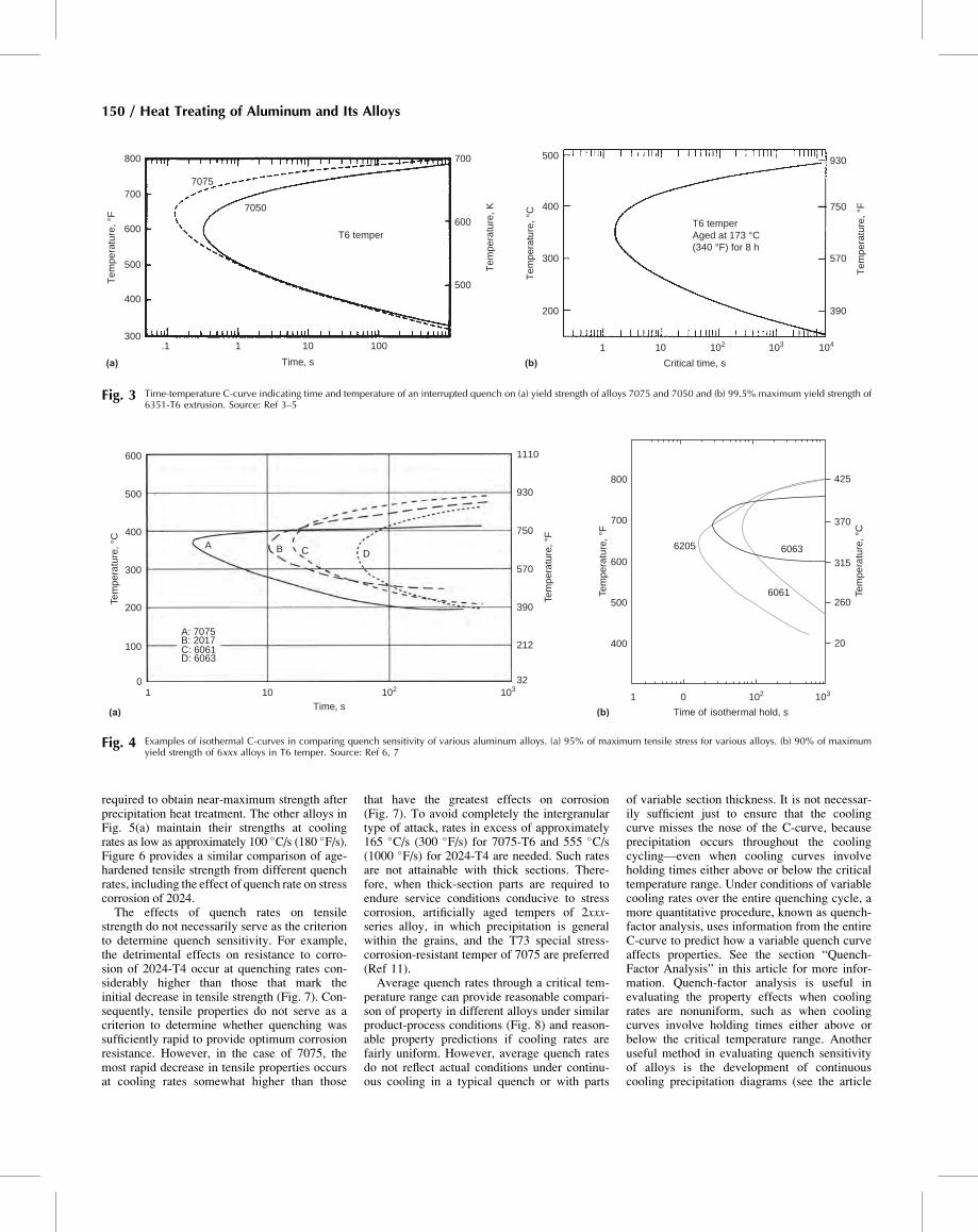
temperature-transformation diagrams to comparethe quench sensitivity of aluminum alloys.Figures 3 and 4 are examples of isothermaltransformation diagrams that compare thequench sensitivity of various aluminum alloys.The critical temperature range is roughly in thesame range of 400 to 290 �C (750 to 550 �F),which is the approximate critical temperaturerange typical of many age-hardenable aluminumalloys. Some sources quote this range (or aslightly different range) as the most criticalrange for quenching of many aluminum alloys,but the range can be alloy-dependent.Quench sensitivity of aluminum alloys also
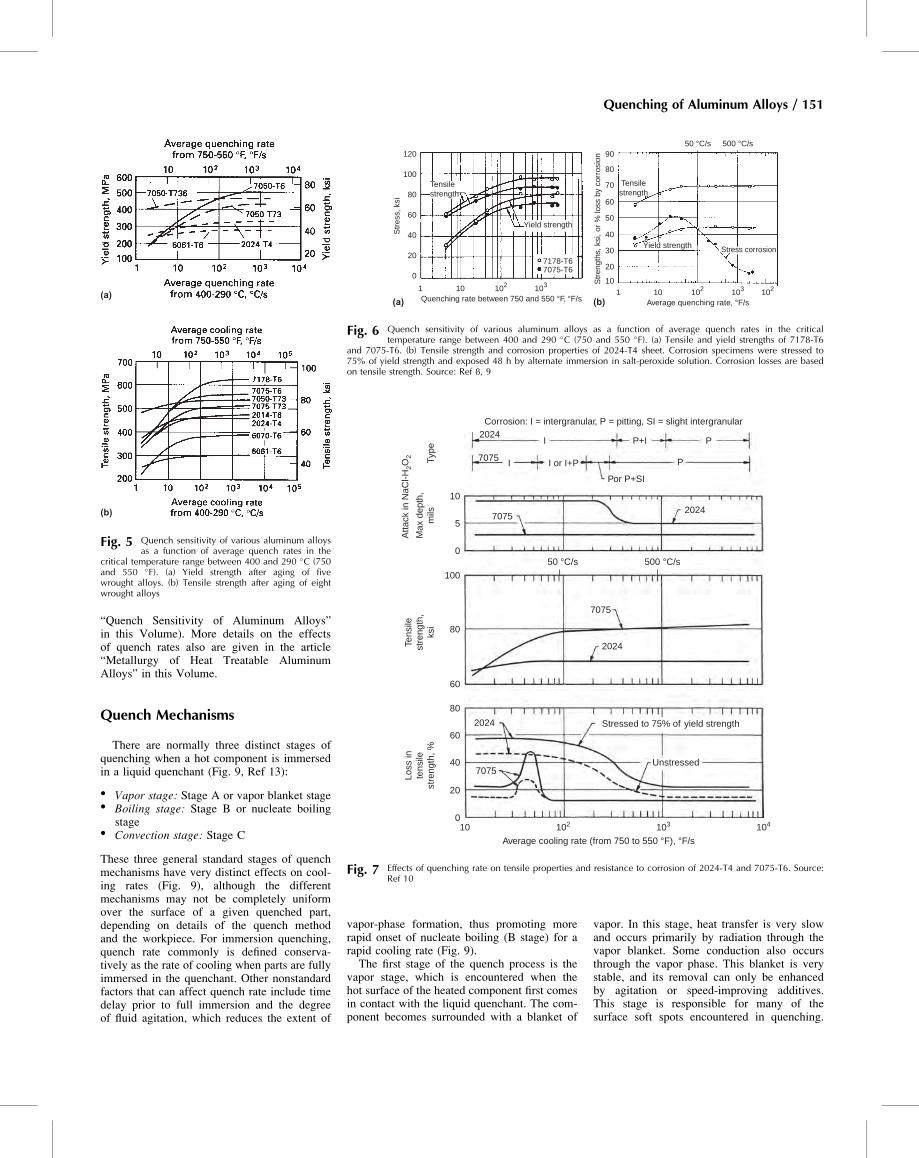
has been evaluated from the effects of averagequenching rates through the critical range from400 to 290 �C (750 to 550 �F). In Fig. 5(a), forexample, the effects of quenching on the yieldstrength of five alloys are compared in termsof average quenching rates through the criticalrange from 400 to 290 �C (750 to 550 �F).For alloys relatively high in sensitivity toquenching rate, such as 7075, rates of approxi-mately 300 �C/s (540 �F/s) or higher are
Fig. 1 Effect of temperature on the extent ofsupersaturation and diffusion rate, which drivethe rate of precipitation
900
800
100% 98% 90%
700
600
500
400
300
200
(a)
10–1 1 10
Time, s Time, s
102 103
Tem
pera
ture
, °C
Tem
pera
ture
, °F
Tem
pera
ture
, °F
Tem
pera
ture
, °C
900
800
700
Type of corrosion attack
Pitting plus slight intergranularPitting plus intergranularintergranular
Pitting
600
500
400
300
200
(b)
10–1 1 10 102 103
80%
400
300
200
Tensile strengthYield strength
400
300
200
Fig. 2 Time-temperature C-curve indicating the effect of time and temperature of an interrupted quench on (a) strength of alloy 7075 as a percentage of maximum from anuninterrupted quench and (b) type of corrosion attack in 2024-T4 sheet. Source: Ref 2
Quenching of Aluminum Alloys / 149
required to obtain near-maximum strength afterprecipitation heat treatment. The other alloys inFig. 5(a) maintain their strengths at coolingrates as low as approximately 100 �C/s (180 �F/s).Figure 6 provides a similar comparison of age-hardened tensile strength from different quenchrates, including the effect of quench rate on stresscorrosion of 2024.The effects of quench rates on tensile
strength do not necessarily serve as the criterionto determine quench sensitivity. For example,the detrimental effects on resistance to corro-sion of 2024-T4 occur at quenching rates con-siderably higher than those that mark theinitial decrease in tensile strength (Fig. 7). Con-sequently, tensile properties do not serve as acriterion to determine whether quenching wassufficiently rapid to provide optimum corrosionresistance. However, in the case of 7075, themost rapid decrease in tensile properties occursat cooling rates somewhat higher than those
that have the greatest effects on corrosion(Fig. 7). To avoid completely the intergranulartype of attack, rates in excess of approximately165 �C/s (300 �F/s) for 7075-T6 and 555 �C/s(1000 �F/s) for 2024-T4 are needed. Such ratesare not attainable with thick sections. There-fore, when thick-section parts are required toendure service conditions conducive to stresscorrosion, artificially aged tempers of 2xxx-series alloy, in which precipitation is generalwithin the grains, and the T73 special stress-corrosion-resistant temper of 7075 are preferred(Ref 11).Average quench rates through a critical tem-
perature range can provide reasonable compari-son of property in different alloys under similarproduct-process conditions (Fig. 8) and reason-able property predictions if cooling rates arefairly uniform. However, average quench ratesdo not reflect actual conditions under continu-ous cooling in a typical quench or with parts
of variable section thickness. It is not necessar-ily sufficient just to ensure that the coolingcurve misses the nose of the C-curve, becauseprecipitation occurs throughout the coolingcycling—even when cooling curves involveholding times either above or below the criticaltemperature range. Under conditions of variablecooling rates over the entire quenching cycle, amore quantitative procedure, known as quench-factor analysis, uses information from the entireC-curve to predict how a variable quench curveaffects properties. See the section “Quench-Factor Analysis” in this article for more infor-mation. Quench-factor analysis is useful inevaluating the property effects when coolingrates are nonuniform, such as when coolingcurves involve holding times either above orbelow the critical temperature range. Anotheruseful method in evaluating quench sensitivityof alloys is the development of continuouscooling precipitation diagrams (see the article
800
7050
500
400
300
200
1 10
Critical time, sTime, s
102 103 104
7075
700
600
500
400
300
(a) (b).1 1 10 100
500
600
390
570
750
T6 temper
Aged at 173 °C
(340 °F) for 8 h
T6 temper
930700
Te
mp
era
ture
, °F
Te
mp
era
ture
, °C
Te
mp
era
ture
, K
Te
mp
era
ture
, °F
Fig. 3 Time-temperature C-curve indicating time and temperature of an interrupted quench on (a) yield strength of alloys 7075 and 7050 and (b) 99.5% maximum yield strength of6351-T6 extrusion. Source: Ref 3–5
60636205
800
700
600
500
400
1 0 102 103
6061
425
370
315
260
20A: 7075
A B C D
B: 2017C: 6061D: 6063
600
500
400
300
200
100
01 10 103102
Time of isothermal hold, sTime, s
32
212
390
570
750
930
1110
(a)
Tem
pera
ture
, °F
Tem
pera
ture
, °F
Tem
pera
ture
, °C
Tem
pera
ture
, °C
(b)
Fig. 4 Examples of isothermal C-curves in comparing quench sensitivity of various aluminum alloys. (a) 95% of maximum tensile stress for various alloys. (b) 90% of maximumyield strength of 6xxx alloys in T6 temper. Source: Ref 6, 7
150 / Heat Treating of Aluminum and Its Alloys
“Quench Sensitivity of Aluminum Alloys”in this Volume). More details on the effectsof quench rates also are given in the article“Metallurgy of Heat Treatable AluminumAlloys” in this Volume.
Quench Mechanisms
There are normally three distinct stages ofquenching when a hot component is immersedin a liquid quenchant (Fig. 9, Ref 13):
� Vapor stage: Stage A or vapor blanket stage� Boiling stage: Stage B or nucleate boiling
stage� Convection stage: Stage C
These three general standard stages of quenchmechanisms have very distinct effects on cool-ing rates (Fig. 9), although the differentmechanisms may not be completely uniformover the surface of a given quenched part,depending on details of the quench methodand the workpiece. For immersion quenching,quench rate commonly is defined conserva-tively as the rate of cooling when parts are fullyimmersed in the quenchant. Other nonstandardfactors that can affect quench rate include timedelay prior to full immersion and the degreeof fluid agitation, which reduces the extent of
vapor-phase formation, thus promoting morerapid onset of nucleate boiling (B stage) for arapid cooling rate (Fig. 9).The first stage of the quench process is the
vapor stage, which is encountered when thehot surface of the heated component first comesin contact with the liquid quenchant. The com-ponent becomes surrounded with a blanket of
vapor. In this stage, heat transfer is very slowand occurs primarily by radiation through thevapor blanket. Some conduction also occursthrough the vapor phase. This blanket is verystable, and its removal can only be enhancedby agitation or speed-improving additives.This stage is responsible for many of thesurface soft spots encountered in quenching.
(a)
(b)
Fig. 5 Quench sensitivity of various aluminum alloysas a function of average quench rates in the
critical temperature range between 400 and 290 �C (750and 550 �F). (a) Yield strength after aging of fivewrought alloys. (b) Tensile strength after aging of eightwrought alloys
Str
ess,
ksi
Str
engt
hs, k
si, o
r %
loss
by
corr
osio
n120
100
80
60
40
20
0
(a) Quenching rate between 750 and 550 °F, °F/s1 10210 103
Yield strength
Yield strength
7178-T67075-T6
Average quenching rate, °F/s
50 °C/s 500 °C/s
102103102101
90
80
70
60
50
40
30
20
10
(b)
Tensilestrength
Stress corrosion
Tensilestrength
Fig. 6 Quench sensitivity of various aluminum alloys as a function of average quench rates in the criticaltemperature range between 400 and 290 �C (750 and 550 �F). (a) Tensile and yield strengths of 7178-T6
and 7075-T6. (b) Tensile strength and corrosion properties of 2024-T4 sheet. Corrosion specimens were stressed to75% of yield strength and exposed 48 h by alternate immersion in salt-peroxide solution. Corrosion losses are basedon tensile strength. Source: Ref 8, 9
Corrosion: I = intergranular, P = pitting, SI = slight intergranular2024
7075
7075
Atta
ck in
NaC
l-H2O
2
Max
dep
th,
mils
Tens
ilest
reng
th,
ksi
Loss
inte
nsile
stre
ngth
, %Ty
pe
10
5
0
100
80
60
80
60
40
20
010 102 103 104
7075
2024
2024
2024
7075
Stressed to 75% of yield strength
Average cooling rate (from 750 to 550 °F), °F/s
50 °C/s 500 °C/s
Unstressed
I
I
P+I P
P
Por P+SI
I or I+P
Fig. 7 Effects of quenching rate on tensile properties and resistance to corrosion of 2024-T4 and 7075-T6. Source:Ref 10
Quenching of Aluminum Alloys / 151
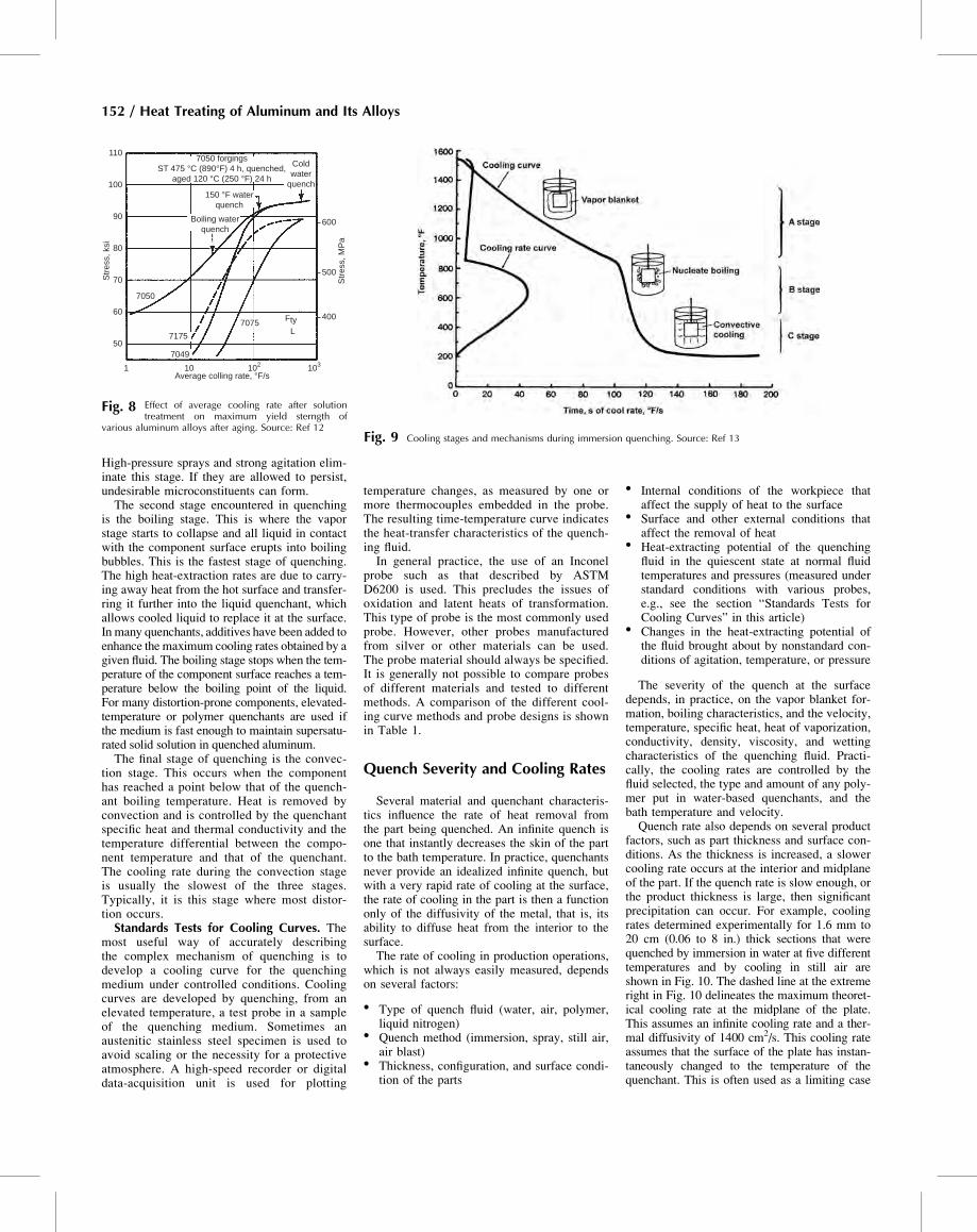
High-pressure sprays and strong agitation elim-inate this stage. If they are allowed to persist,undesirable microconstituents can form.The second stage encountered in quenching
is the boiling stage. This is where the vaporstage starts to collapse and all liquid in contactwith the component surface erupts into boilingbubbles. This is the fastest stage of quenching.The high heat-extraction rates are due to carry-ing away heat from the hot surface and transfer-ring it further into the liquid quenchant, whichallows cooled liquid to replace it at the surface.In many quenchants, additives have been added toenhance the maximum cooling rates obtained by agiven fluid. The boiling stage stops when the tem-perature of the component surface reaches a tem-perature below the boiling point of the liquid.For many distortion-prone components, elevated-temperature or polymer quenchants are used ifthe medium is fast enough to maintain supersatu-rated solid solution in quenched aluminum.The final stage of quenching is the convec-
tion stage. This occurs when the componenthas reached a point below that of the quench-ant boiling temperature. Heat is removed byconvection and is controlled by the quenchantspecific heat and thermal conductivity and thetemperature differential between the compo-nent temperature and that of the quenchant.The cooling rate during the convection stageis usually the slowest of the three stages.Typically, it is this stage where most distor-tion occurs.Standards Tests for Cooling Curves. The
most useful way of accurately describingthe complex mechanism of quenching is todevelop a cooling curve for the quenchingmedium under controlled conditions. Coolingcurves are developed by quenching, from anelevated temperature, a test probe in a sampleof the quenching medium. Sometimes anaustenitic stainless steel specimen is used toavoid scaling or the necessity for a protectiveatmosphere. A high-speed recorder or digitaldata-acquisition unit is used for plotting
temperature changes, as measured by one ormore thermocouples embedded in the probe.The resulting time-temperature curve indicatesthe heat-transfer characteristics of the quench-ing fluid.In general practice, the use of an Inconel
probe such as that described by ASTMD6200 is used. This precludes the issues ofoxidation and latent heats of transformation.This type of probe is the most commonly usedprobe. However, other probes manufacturedfrom silver or other materials can be used.The probe material should always be specified.It is generally not possible to compare probesof different materials and tested to differentmethods. A comparison of the different cool-ing curve methods and probe designs is shownin Table 1.
Quench Severity and Cooling Rates
Several material and quenchant characteris-tics influence the rate of heat removal fromthe part being quenched. An infinite quench isone that instantly decreases the skin of the partto the bath temperature. In practice, quenchantsnever provide an idealized infinite quench, butwith a very rapid rate of cooling at the surface,the rate of cooling in the part is then a functiononly of the diffusivity of the metal, that is, itsability to diffuse heat from the interior to thesurface.The rate of cooling in production operations,
which is not always easily measured, dependson several factors:
� Type of quench fluid (water, air, polymer,liquid nitrogen)
� Quench method (immersion, spray, still air,air blast)
� Thickness, configuration, and surface condi-tion of the parts
� Internal conditions of the workpiece thataffect the supply of heat to the surface
� Surface and other external conditions thataffect the removal of heat
� Heat-extracting potential of the quenchingfluid in the quiescent state at normal fluidtemperatures and pressures (measured understandard conditions with various probes,e.g., see the section “Standards Tests forCooling Curves” in this article)
� Changes in the heat-extracting potential ofthe fluid brought about by nonstandard con-ditions of agitation, temperature, or pressure
The severity of the quench at the surfacedepends, in practice, on the vapor blanket for-mation, boiling characteristics, and the velocity,temperature, specific heat, heat of vaporization,conductivity, density, viscosity, and wettingcharacteristics of the quenching fluid. Practi-cally, the cooling rates are controlled by thefluid selected, the type and amount of any poly-mer put in water-based quenchants, and thebath temperature and velocity.Quench rate also depends on several product
factors, such as part thickness and surface con-ditions. As the thickness is increased, a slowercooling rate occurs at the interior and midplaneof the part. If the quench rate is slow enough, orthe product thickness is large, then significantprecipitation can occur. For example, coolingrates determined experimentally for 1.6 mm to20 cm (0.06 to 8 in.) thick sections that werequenched by immersion in water at five differenttemperatures and by cooling in still air areshown in Fig. 10. The dashed line at the extremeright in Fig. 10 delineates the maximum theoret-ical cooling rate at the midplane of the plate.This assumes an infinite cooling rate and a ther-mal diffusivity of 1400 cm2/s. This cooling rateassumes that the surface of the plate has instan-taneously changed to the temperature of thequenchant. This is often used as a limiting case
Str
ess,
MP
a
Average colling rate, °F/s
Str
ess,
ksi
7050 forgingsST 475 °C (890°F) 4 h, quenched,
aged 120 °C (250 °F) 24 h
Coldwater
quench150 °F water
quench
400
500
600
7050
7175
7075 FtyL
7049
1 10 102 103
50
60
70
80
90
100
110
Boiling waterquench
Fig. 8 Effect of average cooling rate after solutiontreatment on maximum yield sterngth of
various aluminum alloys after aging. Source: Ref 12Fig. 9 Cooling stages and mechanisms during immersion quenching. Source: Ref 13
152 / Heat Treating of Aluminum and Its Alloys
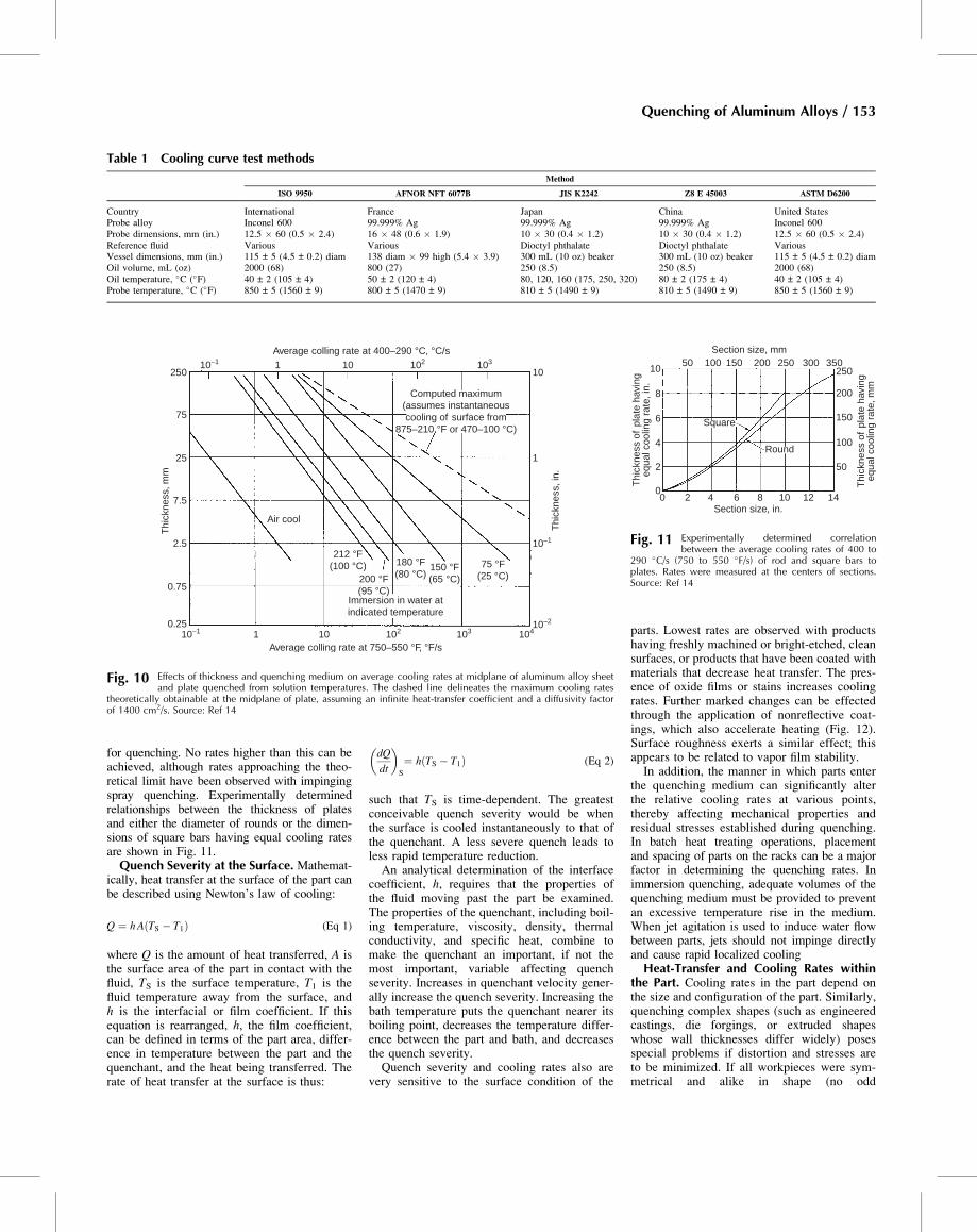
for quenching. No rates higher than this can beachieved, although rates approaching the theo-retical limit have been observed with impingingspray quenching. Experimentally determinedrelationships between the thickness of platesand either the diameter of rounds or the dimen-sions of square bars having equal cooling ratesare shown in Fig. 11.Quench Severity at the Surface. Mathemat-
ically, heat transfer at the surface of the part canbe described using Newton’s law of cooling:
Q ¼ hA TS � T1ð Þ (Eq 1)
where Q is the amount of heat transferred, A isthe surface area of the part in contact with thefluid, TS is the surface temperature, T1 is thefluid temperature away from the surface, andh is the interfacial or film coefficient. If thisequation is rearranged, h, the film coefficient,can be defined in terms of the part area, differ-ence in temperature between the part and thequenchant, and the heat being transferred. Therate of heat transfer at the surface is thus:
dQ
dt
� �S
¼ h TS � T1ð Þ (Eq 2)
such that TS is time-dependent. The greatestconceivable quench severity would be whenthe surface is cooled instantaneously to that ofthe quenchant. A less severe quench leads toless rapid temperature reduction.An analytical determination of the interface
coefficient, h, requires that the properties ofthe fluid moving past the part be examined.The properties of the quenchant, including boil-ing temperature, viscosity, density, thermalconductivity, and specific heat, combine tomake the quenchant an important, if not themost important, variable affecting quenchseverity. Increases in quenchant velocity gener-ally increase the quench severity. Increasing thebath temperature puts the quenchant nearer itsboiling point, decreases the temperature differ-ence between the part and bath, and decreasesthe quench severity.Quench severity and cooling rates also are
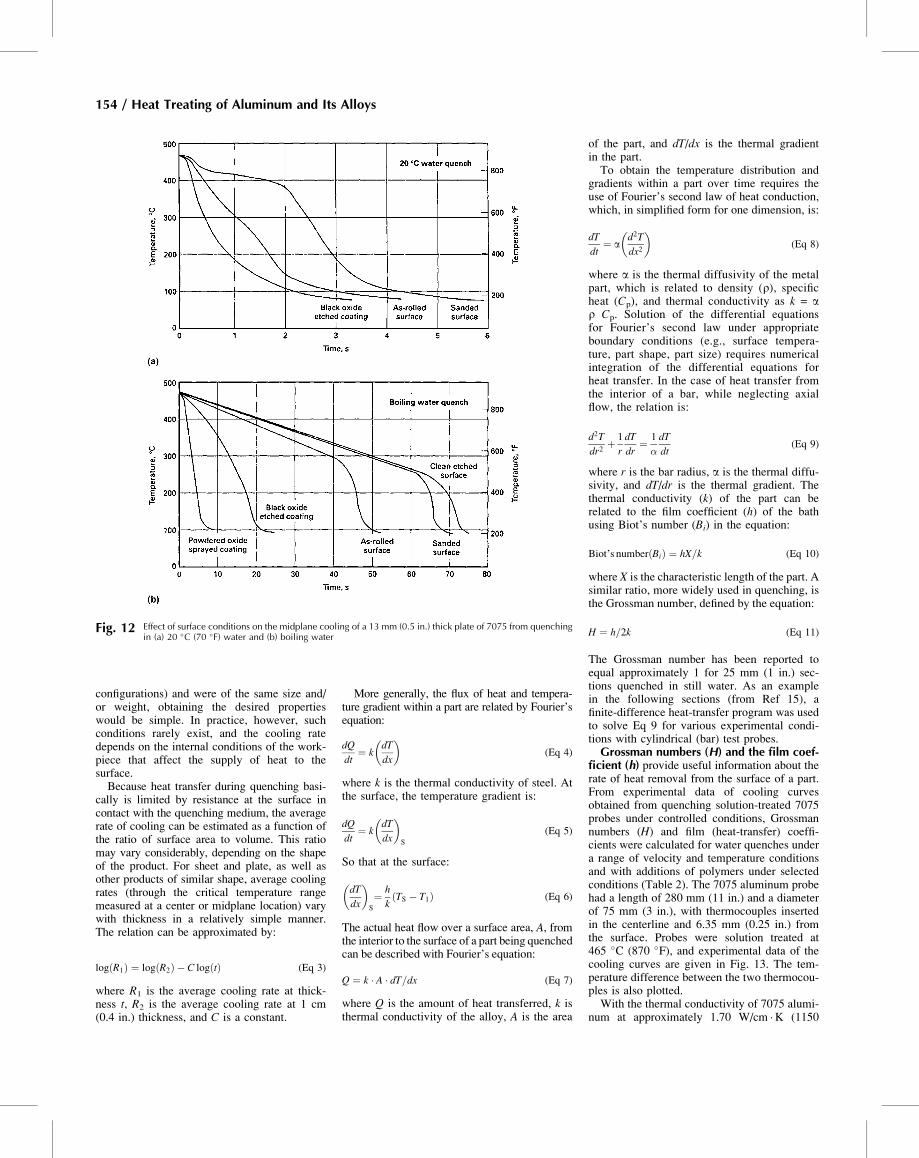
very sensitive to the surface condition of the
parts. Lowest rates are observed with productshaving freshly machined or bright-etched, cleansurfaces, or products that have been coated withmaterials that decrease heat transfer. The pres-ence of oxide films or stains increases coolingrates. Further marked changes can be effectedthrough the application of nonreflective coat-ings, which also accelerate heating (Fig. 12).Surface roughness exerts a similar effect; thisappears to be related to vapor film stability.In addition, the manner in which parts enter
the quenching medium can significantly alterthe relative cooling rates at various points,thereby affecting mechanical properties andresidual stresses established during quenching.In batch heat treating operations, placementand spacing of parts on the racks can be a majorfactor in determining the quenching rates. Inimmersion quenching, adequate volumes of thequenching medium must be provided to preventan excessive temperature rise in the medium.When jet agitation is used to induce water flowbetween parts, jets should not impinge directlyand cause rapid localized coolingHeat-Transfer and Cooling Rates within
the Part. Cooling rates in the part depend onthe size and configuration of the part. Similarly,quenching complex shapes (such as engineeredcastings, die forgings, or extruded shapeswhose wall thicknesses differ widely) posesspecial problems if distortion and stresses areto be minimized. If all workpieces were sym-metrical and alike in shape (no odd
Table 1 Cooling curve test methods
Method
ISO 9950 AFNOR NFT 6077B JIS K2242 Z8 E 45003 ASTM D6200
Country International France Japan China United StatesProbe alloy Inconel 600 99.999% Ag 99.999% Ag 99.999% Ag Inconel 600Probe dimensions, mm (in.) 12.5 � 60 (0.5 � 2.4) 16 � 48 (0.6 � 1.9) 10 � 30 (0.4 � 1.2) 10 � 30 (0.4 � 1.2) 12.5 � 60 (0.5 � 2.4)Reference fluid Various Various Dioctyl phthalate Dioctyl phthalate VariousVessel dimensions, mm (in.) 115 ± 5 (4.5 ± 0.2) diam 138 diam � 99 high (5.4 � 3.9) 300 mL (10 oz) beaker 300 mL (10 oz) beaker 115 ± 5 (4.5 ± 0.2) diamOil volume, mL (oz) 2000 (68) 800 (27) 250 (8.5) 250 (8.5) 2000 (68)Oil temperature, �C (�F) 40 ± 2 (105 ± 4) 50 ± 2 (120 ± 4) 80, 120, 160 (175, 250, 320) 80 ± 2 (175 ± 4) 40 ± 2 (105 ± 4)Probe temperature, �C (�F) 850 ± 5 (1560 ± 9) 800 ± 5 (1470 ± 9) 810 ± 5 (1490 ± 9) 810 ± 5 (1490 ± 9) 850 ± 5 (1560 ± 9)
250
75
25
7.5
2.5
0.75
0.2510–1 1 10
Immersion in water atindicated temperature
75 °F(25 °C)
150 °F(65 °C)
180 °F(80 °C)200 °F
(95 °C)
212 °F(100 °C)
Air cool
Computed maximum(assumes instantaneouscooling of surface from
875–210 °F or 470–100 °C)
10
1
10–1
10–2
Thi
ckne
ss, i
n.
Thi
ckne
ss, m
m
102
10310210110–1
103 104
Average colling rate at 750–550 °F, °F/s
Average colling rate at 400–290 °C, °C/s
Fig. 10 Effects of thickness and quenching medium on average cooling rates at midplane of aluminum alloy sheetand plate quenched from solution temperatures. The dashed line delineates the maximum cooling rates
theoretically obtainable at the midplane of plate, assuming an infinite heat-transfer coefficient and a diffusivity factorof 1400 cm2/s. Source: Ref 14
50 100 150 200 250 300 350250
200
150
10
8
6
4
2
0
Thi
ckne
ss o
f pl
ate
hav
ing
equa
l coo
ling
rate
, in.
Thi
ckne
ss o
f pl
ate
hav
ing
equa
l coo
ling
rate
, mm
100
50
1412108642Section size, in.
Section size, mm
0
Square
Round
Fig. 11 Experimentally determined correlationbetween the average cooling rates of 400 to
290 �C/s (750 to 550 �F/s) of rod and square bars toplates. Rates were measured at the centers of sections.Source: Ref 14
Quenching of Aluminum Alloys / 153
configurations) and were of the same size and/or weight, obtaining the desired propertieswould be simple. In practice, however, suchconditions rarely exist, and the cooling ratedepends on the internal conditions of the work-piece that affect the supply of heat to thesurface.Because heat transfer during quenching basi-
cally is limited by resistance at the surface incontact with the quenching medium, the averagerate of cooling can be estimated as a function ofthe ratio of surface area to volume. This ratiomay vary considerably, depending on the shapeof the product. For sheet and plate, as well asother products of similar shape, average coolingrates (through the critical temperature rangemeasured at a center or midplane location) varywith thickness in a relatively simple manner.The relation can be approximated by:
log R1ð Þ ¼ log R2ð Þ � C log tð Þ (Eq 3)
where R1 is the average cooling rate at thick-ness t, R2 is the average cooling rate at 1 cm(0.4 in.) thickness, and C is a constant.
More generally, the flux of heat and tempera-ture gradient within a part are related by Fourier’sequation:
dQ
dt¼ k
dT
dx
� �(Eq 4)
where k is the thermal conductivity of steel. Atthe surface, the temperature gradient is:
dQ
dt¼ k
dT
dx
� �S
(Eq 5)
So that at the surface:
dT
dx
� �S
¼ h
kTS � T1ð Þ (Eq 6)
The actual heat flow over a surface area, A, fromthe interior to the surface of a part being quenchedcan be described with Fourier’s equation:
Q ¼ k � A � dT=dx (Eq 7)
where Q is the amount of heat transferred, k isthermal conductivity of the alloy, A is the area
of the part, and dT/dx is the thermal gradientin the part.To obtain the temperature distribution and
gradients within a part over time requires theuse of Fourier’s second law of heat conduction,which, in simplified form for one dimension, is:
dT
dt¼ a
d2T
dx2
� �(Eq 8)
where a is the thermal diffusivity of the metalpart, which is related to density (r), specificheat (Cp), and thermal conductivity as k = ar Cp. Solution of the differential equationsfor Fourier’s second law under appropriateboundary conditions (e.g., surface tempera-ture, part shape, part size) requires numericalintegration of the differential equations forheat transfer. In the case of heat transfer fromthe interior of a bar, while neglecting axialflow, the relation is:
d2T
dr2þ 1
r
dT
dr¼ 1
�
dT
dt(Eq 9)
where r is the bar radius, a is the thermal diffu-sivity, and dT/dr is the thermal gradient. Thethermal conductivity (k) of the part can berelated to the film coefficient (h) of the bathusing Biot’s number (Bi) in the equation:
Biot’s number Bið Þ ¼ hX=k (Eq 10)
where X is the characteristic length of the part. Asimilar ratio, more widely used in quenching, isthe Grossman number, defined by the equation:
H ¼ h=2k (Eq 11)
The Grossman number has been reported toequal approximately 1 for 25 mm (1 in.) sec-tions quenched in still water. As an examplein the following sections (from Ref 15), afinite-difference heat-transfer program was usedto solve Eq 9 for various experimental condi-tions with cylindrical (bar) test probes.Grossman numbers (H) and the film coef-
ficient (h) provide useful information about therate of heat removal from the surface of a part.From experimental data of cooling curvesobtained from quenching solution-treated 7075probes under controlled conditions, Grossmannumbers (H) and film (heat-transfer) coeffi-cients were calculated for water quenches undera range of velocity and temperature conditionsand with additions of polymers under selectedconditions (Table 2). The 7075 aluminum probehad a length of 280 mm (11 in.) and a diameterof 75 mm (3 in.), with thermocouples insertedin the centerline and 6.35 mm (0.25 in.) fromthe surface. Probes were solution treated at465 �C (870 �F), and experimental data of thecooling curves are given in Fig. 13. The tem-perature difference between the two thermocou-ples is also plotted.With the thermal conductivity of 7075 alumi-
num at approximately 1.70 W/cm �K (1150
Fig. 12 Effect of surface conditions on the midplane cooling of a 13 mm (0.5 in.) thick plate of 7075 from quenchingin (a) 20 �C (70 �F) water and (b) boiling water
154 / Heat Treating of Aluminum and Its Alloys
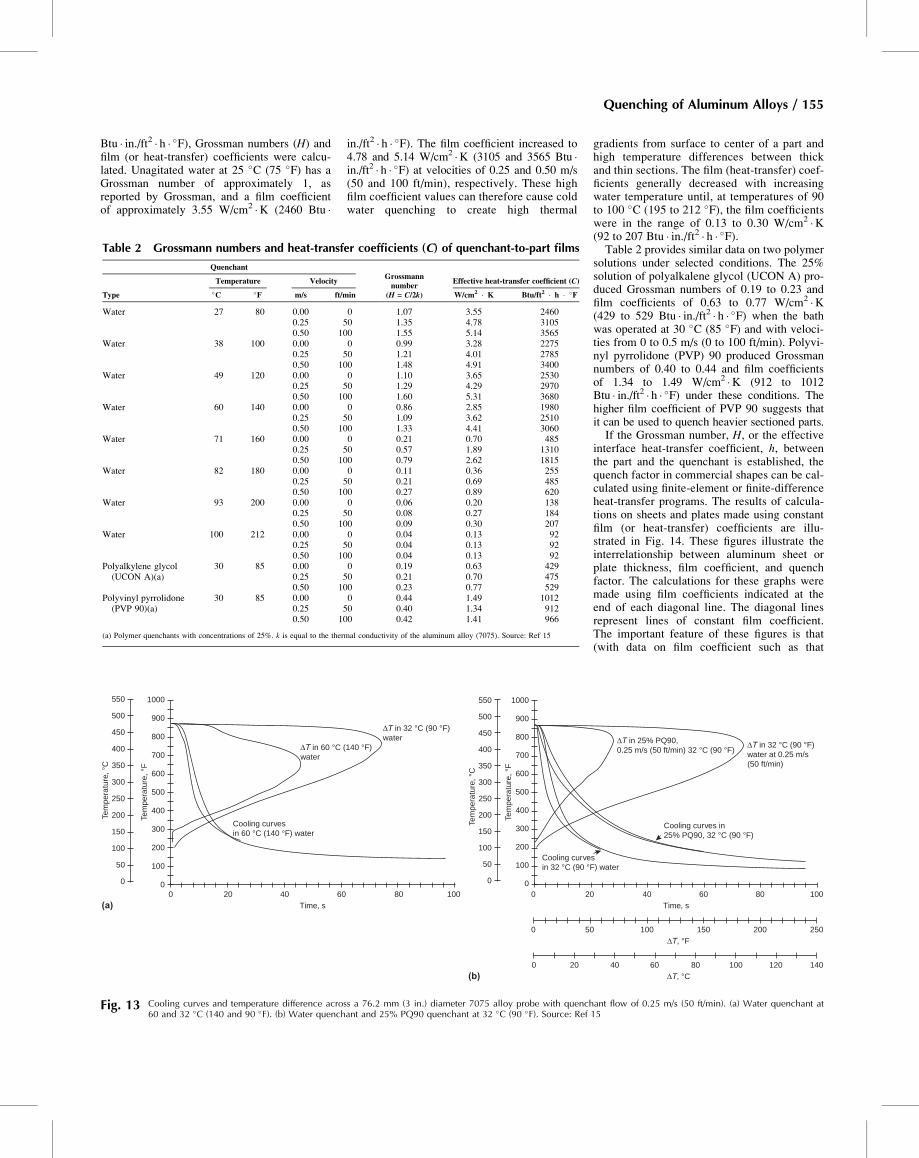
Btu � in./ft2 � h � �F), Grossman numbers (H) andfilm (or heat-transfer) coefficients were calcu-lated. Unagitated water at 25 �C (75 �F) has aGrossman number of approximately 1, asreported by Grossman, and a film coefficientof approximately 3.55 W/cm2 �K (2460 Btu �
in./ft2 � h � �F). The film coefficient increased to4.78 and 5.14 W/cm2 �K (3105 and 3565 Btu �in./ft2 � h � �F) at velocities of 0.25 and 0.50 m/s(50 and 100 ft/min), respectively. These highfilm coefficient values can therefore cause coldwater quenching to create high thermal
gradients from surface to center of a part andhigh temperature differences between thickand thin sections. The film (heat-transfer) coef-ficients generally decreased with increasingwater temperature until, at temperatures of 90to 100 �C (195 to 212 �F), the film coefficientswere in the range of 0.13 to 0.30 W/cm2 �K(92 to 207 Btu � in./ft2 � h � �F).Table 2 provides similar data on two polymer
solutions under selected conditions. The 25%solution of polyalkalene glycol (UCON A) pro-duced Grossman numbers of 0.19 to 0.23 andfilm coefficients of 0.63 to 0.77 W/cm2 �K(429 to 529 Btu � in./ft2 � h � �F) when the bathwas operated at 30 �C (85 �F) and with veloci-ties from 0 to 0.5 m/s (0 to 100 ft/min). Polyvi-nyl pyrrolidone (PVP) 90 produced Grossmannumbers of 0.40 to 0.44 and film coefficientsof 1.34 to 1.49 W/cm2 �K (912 to 1012Btu � in./ft2 � h � �F) under these conditions. Thehigher film coefficient of PVP 90 suggests thatit can be used to quench heavier sectioned parts.If the Grossman number, H, or the effective
interface heat-transfer coefficient, h, betweenthe part and the quenchant is established, thequench factor in commercial shapes can be cal-culated using finite-element or finite-differenceheat-transfer programs. The results of calcula-tions on sheets and plates made using constantfilm (or heat-transfer) coefficients are illu-strated in Fig. 14. These figures illustrate theinterrelationship between aluminum sheet orplate thickness, film coefficient, and quenchfactor. The calculations for these graphs weremade using film coefficients indicated at theend of each diagonal line. The diagonal linesrepresent lines of constant film coefficient.The important feature of these figures is that(with data on film coefficient such as that
Table 2 Grossmann numbers and heat-transfer coefficients (C) of quenchant-to-part films
QuenchantGrossmannnumber
(H = C/2k)
Effective heat-transfer coefficient (C)
Type
Temperature Velocity
�C �F m/s ft/min W/cm2 � K Btu/ft2 � h � �F
Water 27 80 0.00 0 1.07 3.55 24600.25 50 1.35 4.78 31050.50 100 1.55 5.14 3565
Water 38 100 0.00 0 0.99 3.28 22750.25 50 1.21 4.01 27850.50 100 1.48 4.91 3400
Water 49 120 0.00 0 1.10 3.65 25300.25 50 1.29 4.29 29700.50 100 1.60 5.31 3680
Water 60 140 0.00 0 0.86 2.85 19800.25 50 1.09 3.62 25100.50 100 1.33 4.41 3060
Water 71 160 0.00 0 0.21 0.70 4850.25 50 0.57 1.89 13100.50 100 0.79 2.62 1815
Water 82 180 0.00 0 0.11 0.36 2550.25 50 0.21 0.69 4850.50 100 0.27 0.89 620
Water 93 200 0.00 0 0.06 0.20 1380.25 50 0.08 0.27 1840.50 100 0.09 0.30 207
Water 100 212 0.00 0 0.04 0.13 920.25 50 0.04 0.13 920.50 100 0.04 0.13 92
Polyalkylene glycol(UCON A)(a)
30 85 0.00 0 0.19 0.63 4290.25 50 0.21 0.70 4750.50 100 0.23 0.77 529
Polyvinyl pyrrolidone(PVP 90)(a)
30 85 0.00 0 0.44 1.49 10120.25 50 0.40 1.34 9120.50 100 0.42 1.41 966
(a) Polymer quenchants with concentrations of 25%. k is equal to the thermal conductivity of the aluminum alloy (7075). Source: Ref 15
ΔT in 60 °C (140 °F)water
Cooling curvesin 60 °C (140 °F) water
Time, s
ΔT in 32 °C (90 °F)water
1000
900
800
700
600
500
400
300
200
100
00 20 40 60 80 100
550
500
450
400
350
300
250
200
150
100
50
0
(a)
Tem
pera
ture
, °C
Tem
pera
ture
, °F
Time, s
ΔT, °F
ΔT, °C(b)
Tem
pera
ture
, °C
Tem
pera
ture
, °F
ΔT in 32 °C (90 °F)water at 0.25 m/s(50 ft/min)
ΔT in 25% PQ90,0.25 m/s (50 ft/min) 32 °C (90 °F)
Cooling curves in25% PQ90, 32 °C (90 °F)
Cooling curvesin 32 °C (90 °F) water
1000
900
800
700
600
500
400
300
200
100
00 20 40 60 80 100
0 50 100 150 200 250
140120100806040200
550
500
450
400
350
300
250
200
150
100
50
0
Fig. 13 Cooling curves and temperature difference across a 76.2 mm (3 in.) diameter 7075 alloy probe with quenchant flow of 0.25 m/s (50 ft/min). (a) Water quenchant at60 and 32 �C (140 and 90 �F). (b) Water quenchant and 25% PQ90 quenchant at 32 �C (90 �F). Source: Ref 15
Quenching of Aluminum Alloys / 155
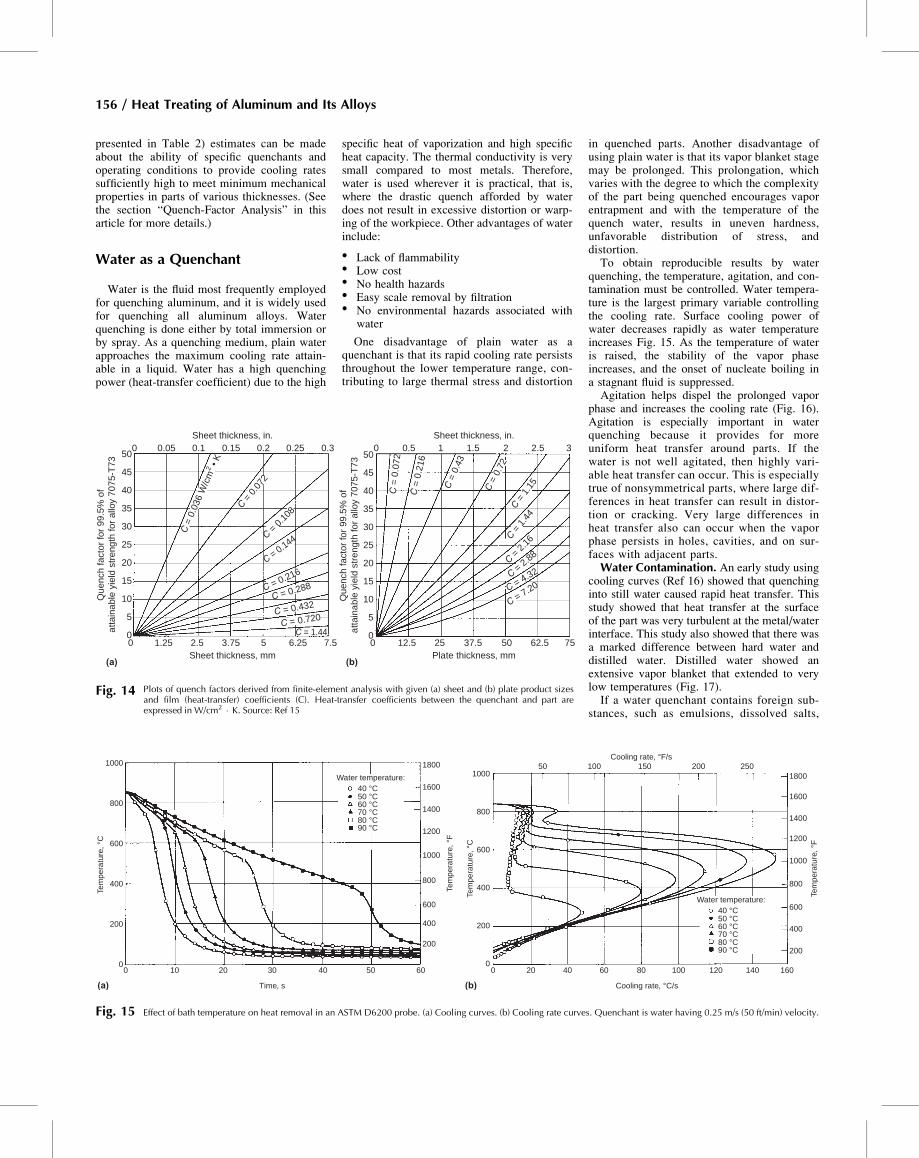
presented in Table 2) estimates can be madeabout the ability of specific quenchants andoperating conditions to provide cooling ratessufficiently high to meet minimum mechanicalproperties in parts of various thicknesses. (Seethe section “Quench-Factor Analysis” in thisarticle for more details.)
Water as a Quenchant
Water is the fluid most frequently employedfor quenching aluminum, and it is widely usedfor quenching all aluminum alloys. Waterquenching is done either by total immersion orby spray. As a quenching medium, plain waterapproaches the maximum cooling rate attain-able in a liquid. Water has a high quenchingpower (heat-transfer coefficient) due to the high
specific heat of vaporization and high specificheat capacity. The thermal conductivity is verysmall compared to most metals. Therefore,water is used wherever it is practical, that is,where the drastic quench afforded by waterdoes not result in excessive distortion or warp-ing of the workpiece. Other advantages of waterinclude:
� Lack of flammability� Low cost� No health hazards� Easy scale removal by filtration� No environmental hazards associated with
water
One disadvantage of plain water as aquenchant is that its rapid cooling rate persiststhroughout the lower temperature range, con-tributing to large thermal stress and distortion
in quenched parts. Another disadvantage ofusing plain water is that its vapor blanket stagemay be prolonged. This prolongation, whichvaries with the degree to which the complexityof the part being quenched encourages vaporentrapment and with the temperature of thequench water, results in uneven hardness,unfavorable distribution of stress, anddistortion.To obtain reproducible results by water
quenching, the temperature, agitation, and con-tamination must be controlled. Water tempera-ture is the largest primary variable controllingthe cooling rate. Surface cooling power ofwater decreases rapidly as water temperatureincreases Fig. 15. As the temperature of wateris raised, the stability of the vapor phaseincreases, and the onset of nucleate boiling ina stagnant fluid is suppressed.Agitation helps dispel the prolonged vapor
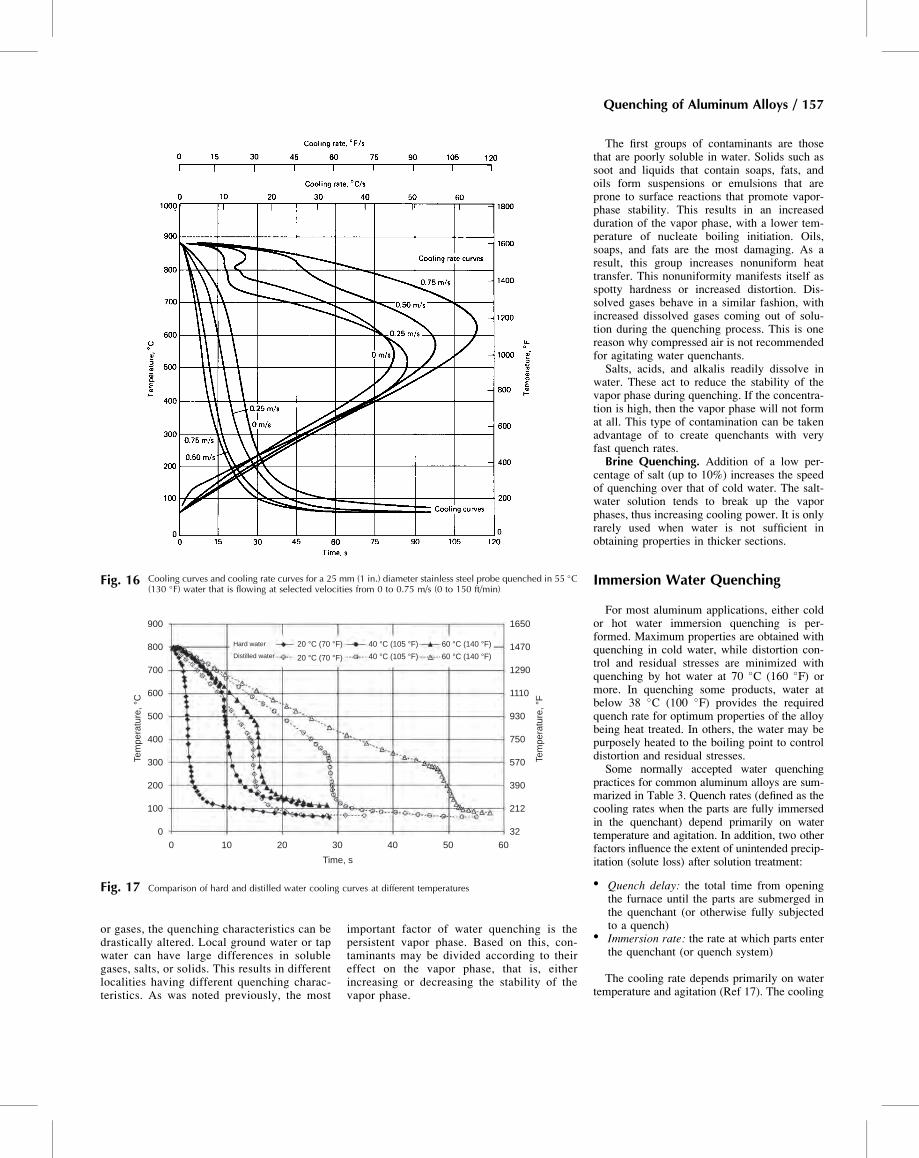
phase and increases the cooling rate (Fig. 16).Agitation is especially important in waterquenching because it provides for moreuniform heat transfer around parts. If thewater is not well agitated, then highly vari-able heat transfer can occur. This is especiallytrue of nonsymmetrical parts, where large dif-ferences in heat transfer can result in distor-tion or cracking. Very large differences inheat transfer also can occur when the vaporphase persists in holes, cavities, and on sur-faces with adjacent parts.Water Contamination. An early study using
cooling curves (Ref 16) showed that quenchinginto still water caused rapid heat transfer. Thisstudy showed that heat transfer at the surfaceof the part was very turbulent at the metal/waterinterface. This study also showed that there wasa marked difference between hard water anddistilled water. Distilled water showed anextensive vapor blanket that extended to verylow temperatures (Fig. 17).If a water quenchant contains foreign sub-
stances, such as emulsions, dissolved salts,
050
45
40
35
30
25
20
15
10
5
0
(a) (b)Sheet thickness, mm
Sheet thickness, in.
Que
nch
fact
or fo
r 99
.5%
of
atta
ina
ble
yiel
d st
reng
th fo
r al
loy
7075
-T73
Que
nch
fact
or fo
r 99
.5%
of
atta
ina
ble
yiel
d st
reng
th fo
r al
loy
7075
-T73
C = 1.440 1.25 2.5 3.75 5 6.25 7.5
Plate thickness, mm0 12.5 25 37.5 50 62.5 75
0.05 0.1 0.15
C = 0.288
C = 0.432
C = 0.720
C = 0
.072
C = 0.144
0.2 0.25 0.3 050
45
40
35
30
25
20
15
10
5
0
C =
0.4
3
C =
0.7
2C =
1.1
5
C = 1
.44
C = 2
.16
C = 2.88
Sheet thickness, in.0.5 1 1.5
C = 4.32
2 2.5 3
C = 0.216
C = 0
.108
C =
0.0
36 W
/cm
2 • K
C =
0.2
16
C =
0.0
72
C = 7.20
Fig. 14 Plots of quench factors derived from finite-element analysis with given (a) sheet and (b) plate product sizesand film (heat-transfer) coefficients (C). Heat-transfer coefficients between the quenchant and part areexpressed in W/cm2 � K. Source: Ref 15
1000
800
600
400
200
00
(a) (b)
10
50 100 150 200 250
20 30
Time, s
Tem
pera
ture
, °F
Tem
pera
ture
, °C
1000
800
600
400
200
0
Tem
pera
ture
, °C
40 50 60 0 20 40 60
Cooling rate, °C/s
Cooling rate, °F/s
80 100 120 140 160
200
400
600
800
1000
1200
1400
1600
1800
Tem
pera
ture
, °F
200
400
600
800
1000
1200
1400
1600
1800Water temperature:40 °C50 °C60 °C70 °C80 °C90 °C
Water temperature:40 °C50 °C60 °C70 °C80 °C90 °C
Fig. 15 Effect of bath temperature on heat removal in an ASTM D6200 probe. (a) Cooling curves. (b) Cooling rate curves. Quenchant is water having 0.25 m/s (50 ft/min) velocity.
156 / Heat Treating of Aluminum and Its Alloys
or gases, the quenching characteristics can bedrastically altered. Local ground water or tapwater can have large differences in solublegases, salts, or solids. This results in differentlocalities having different quenching charac-teristics. As was noted previously, the most
important factor of water quenching is thepersistent vapor phase. Based on this, con-taminants may be divided according to theireffect on the vapor phase, that is, eitherincreasing or decreasing the stability of thevapor phase.
The first groups of contaminants are thosethat are poorly soluble in water. Solids such assoot and liquids that contain soaps, fats, andoils form suspensions or emulsions that areprone to surface reactions that promote vapor-phase stability. This results in an increasedduration of the vapor phase, with a lower tem-perature of nucleate boiling initiation. Oils,soaps, and fats are the most damaging. As aresult, this group increases nonuniform heattransfer. This nonuniformity manifests itself asspotty hardness or increased distortion. Dis-solved gases behave in a similar fashion, withincreased dissolved gases coming out of solu-tion during the quenching process. This is onereason why compressed air is not recommendedfor agitating water quenchants.Salts, acids, and alkalis readily dissolve in
water. These act to reduce the stability of thevapor phase during quenching. If the concentra-tion is high, then the vapor phase will not format all. This type of contamination can be takenadvantage of to create quenchants with veryfast quench rates.Brine Quenching. Addition of a low per-
centage of salt (up to 10%) increases the speedof quenching over that of cold water. The salt-water solution tends to break up the vaporphases, thus increasing cooling power. It is onlyrarely used when water is not sufficient inobtaining properties in thicker sections.
Immersion Water Quenching
For most aluminum applications, either coldor hot water immersion quenching is per-formed. Maximum properties are obtained withquenching in cold water, while distortion con-trol and residual stresses are minimized withquenching by hot water at 70 �C (160 �F) ormore. In quenching some products, water atbelow 38 �C (100 �F) provides the requiredquench rate for optimum properties of the alloybeing heat treated. In others, the water may bepurposely heated to the boiling point to controldistortion and residual stresses.Some normally accepted water quenching
practices for common aluminum alloys are sum-marized in Table 3. Quench rates (defined as thecooling rates when the parts are fully immersedin the quenchant) depend primarily on watertemperature and agitation. In addition, two otherfactors influence the extent of unintended precip-itation (solute loss) after solution treatment:
� Quench delay: the total time from openingthe furnace until the parts are submerged inthe quenchant (or otherwise fully subjectedto a quench)
� Immersion rate: the rate at which parts enterthe quenchant (or quench system)
The cooling rate depends primarily on watertemperature and agitation (Ref 17). The cooling
Fig. 16 Cooling curves and cooling rate curves for a 25 mm (1 in.) diameter stainless steel probe quenched in 55 �C(130 �F) water that is flowing at selected velocities from 0 to 0.75 m/s (0 to 150 ft/min)
Hard water 20 °C (70 °F) 40 °C (105 °F) 60 °C (140 °F)
1650
1470
1290
1110
930
750
570
390
212
32
60 °C (140 °F)40 °C (105 °F)20 °C (70 °F)Distilled water
Time, s
Tem
pera
ture
, °C
Tem
pera
ture
, °F
0 10 20 30 40 50 60
900
800
700
600
500
400
300
200
100
0
Fig. 17 Comparison of hard and distilled water cooling curves at different temperatures
Quenching of Aluminum Alloys / 157
rate of water quenching is independent of mate-rial properties such as thermal conductivity andspecific heat. Water temperature is the largestprimary variable controlling the cooling rate.Surface cooling power of water decreases rap-idly as water temperature increases (Fig. 15).Hot water has a low cooling power because,as the boiling point is approached, the vaporphase becomes prolonged. Agitation is impor-tant, because it provides more uniform heattransfer around parts by disrupting the pro-longed formation of vapor phase. As agitationis increased, the variation in hardness decreasesand distortion decreases.Water at a temperature of 15 to 25 �C (60 to
75 �F) can provide uniform quenching speedand reproducible results. Quenching into waterat less than 50 to 60 �C (120 to 140 �F) oftenproduces nonuniform quenching. This nonuni-formity manifests itself as spotty hardness, dis-tortion, and cracking. This nonuniformity iscaused by relatively unstable vapor blanket for-mation. Because of this difficulty, immersionquenching in cold water usually is restricted tothe quenching of simple, symmetrical parts.Polyalkylene glycol quenchants also are usedto provide a quench rate in between that ofwater and oil. By control of agitation, tempera-ture, and concentration, quench rates similar towater can be achieved.Because rapid cooling rates are achieved with
water at lower temperatures, water near roomtemperature (15 to 25 �C, or 60 to 75 �F) is usedfor many aluminum quenching operations. Thetemperature at the onset of quenching is usuallyin the range of 15 to 30 �C (60 to 90 �F). Mostspecifications limit the temperature of the waterto below 30 �C (90 �F), with the maximum riseof no more than 5 �C (10 �F). This requirementgoverns the design of most quench tanks regard-ing the total volume in an immersion quenchtank. (See the section “Quench Tank Systems”in this article for more details.)Effect of Water Temperature. When water
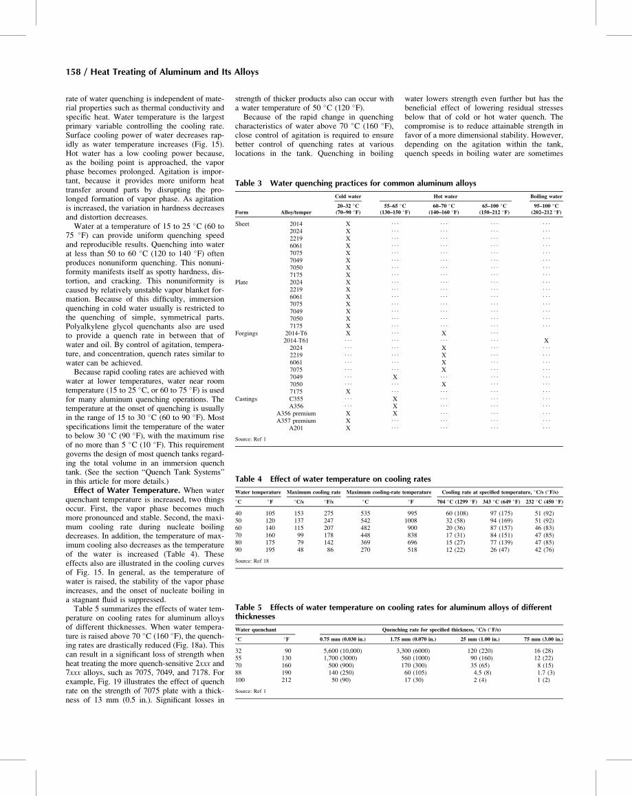
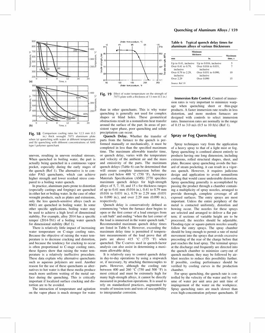
quenchant temperature is increased, two thingsoccur. First, the vapor phase becomes muchmore pronounced and stable. Second, the maxi-mum cooling rate during nucleate boilingdecreases. In addition, the temperature of max-imum cooling also decreases as the temperatureof the water is increased (Table 4). Theseeffects also are illustrated in the cooling curvesof Fig. 15. In general, as the temperature ofwater is raised, the stability of the vapor phaseincreases, and the onset of nucleate boiling ina stagnant fluid is suppressed.Table 5 summarizes the effects of water tem-
perature on cooling rates for aluminum alloysof different thicknesses. When water tempera-ture is raised above 70 �C (160 �F), the quench-ing rates are drastically reduced (Fig. 18a). Thiscan result in a significant loss of strength whenheat treating the more quench-sensitive 2xxx and7xxx alloys, such as 7075, 7049, and 7178. Forexample, Fig. 19 illustrates the effect of quenchrate on the strength of 7075 plate with a thick-ness of 13 mm (0.5 in.). Significant losses in
strength of thicker products also can occur witha water temperature of 50 �C (120 �F).Because of the rapid change in quenching
characteristics of water above 70 �C (160 �F),close control of agitation is required to ensurebetter control of quenching rates at variouslocations in the tank. Quenching in boiling
water lowers strength even further but has thebeneficial effect of lowering residual stressesbelow that of cold or hot water quench. Thecompromise is to reduce attainable strength infavor of a more dimensional stability. However,depending on the agitation within the tank,quench speeds in boiling water are sometimes
Table 3 Water quenching practices for common aluminum alloys
Form Alloy/temper
Cold water Hot water Boiling water
20–32 �C(70–90 �F)
55–65 �C(130–150 �F)
60–70 �C(140–160 �F)
65–100 �C(150–212 �F)
95–100 �C(202–212 �F)
Sheet 2014 X . . . . . . . . . . . .
2024 X . . . . . . . . . . . .
2219 X . . . . . . . . . . . .
6061 X . . . . . . . . . . . .
7075 X . . . . . . . . . . . .
7049 X . . . . . . . . . . . .
7050 X . . . . . . . . . . . .
7175 X . . . . . . . . . . . .
Plate 2024 X . . . . . . . . . . . .
2219 X . . . . . . . . . . . .
6061 X . . . . . . . . . . . .
7075 X . . . . . . . . . . . .
7049 X . . . . . . . . . . . .
7050 X . . . . . . . . . . . .
7175 X . . . . . . . . . . . .
Forgings 2014-T6 X . . . X . . .
2014-T61 . . . . . . . . . . . . X2024 . . . . . . X . . . . . .
2219 . . . . . . X . . . . . .
6061 . . . . . . X . . . . . .
7075 . . . . . . X . . . . . .
7049 . . . X . . . . . . . . .
7050 . . . . . . X . . . . . .
7175 X . . . . . . . . . . . .
Castings C355 . . . X . . . . . . . . .
A356 . . . X . . . . . . . . .
A356 premium X X . . . . . . . . .
A357 premium X . . . . . . . . . . . .
A201 X . . . . . . . . . . . .
Source: Ref 1
Table 4 Effect of water temperature on cooling rates
Water temperature Maximum cooling rate Maximum cooling-rate temperature Cooling rate at specified temperature, �C/s (�F/s)�C �F �C/s �F/s �C �F 704 �C (1299 �F) 343 �C (649 �F) 232 �C (450 �F)
40 105 153 275 535 995 60 (108) 97 (175) 51 (92)50 120 137 247 542 1008 32 (58) 94 (169) 51 (92)60 140 115 207 482 900 20 (36) 87 (157) 46 (83)70 160 99 178 448 838 17 (31) 84 (151) 47 (85)80 175 79 142 369 696 15 (27) 77 (139) 47 (85)90 195 48 86 270 518 12 (22) 26 (47) 42 (76)
Source: Ref 18
Table 5 Effects of water temperature on cooling rates for aluminum alloys of differentthicknesses
Water quenchant Quenching rate for specified thickness, �C/s (�F/s)�C �F 0.75 mm (0.030 in.) 1.75 mm (0.070 in.) 25 mm (1.00 in.) 75 mm (3.00 in.)
32 90 5,600 (10,000) 3,300 (6000) 120 (220) 16 (28)55 130 1,700 (3000) 560 (1000) 90 (160) 12 (22)70 160 500 (900) 170 (300) 35 (65) 8 (15)88 190 140 (250) 60 (105) 4.5 (8) 1.7 (3)100 212 50 (90) 17 (30) 2 (4) 1 (2)
Source: Ref 1
158 / Heat Treating of Aluminum and Its Alloys
uneven, resulting in uneven residual stresses.When quenched in boiling water, the part isactually being quenched in a continuous vaporpocket, especially during the early stages ofthe quench (Ref 1). The alternative is to con-sider PAG quenchants, which can achievehigher strength and lower residual stress com-pared to a boiling water quench.In practice, aluminum parts prone to distortion
(especially castings and forgings) are quenchedin either hot or boiling water. In the case of otherwrought products, such as plates and extrusions,only the less quench-sensitive alloys (such as6061) are quenched in boiling water. In someother specific applications, boiling water maybe used to achieve a high level of dimensionalstability. For example, alloy 2014 has a specifictemper (2014-T61) of a boiling water quenchfor dimensional stability (Ref 1).There is relatively little impact of increasing
water temperature on C-stage cooling rates.Because the objective of raising the water tem-perature is to decrease cracking and distortion,and because the tendency for cracking to occuris often proportional to C-stage cooling rates,these figures show that raising the water tem-perature is a relatively ineffective procedure.These data explain why alternative quenchantssuch as aqueous polymers are used. Anotherreason for the use of these quenchants as alter-natives to hot water is that these media producemuch more uniform wetting of the metal sur-face during the quenching. This is criticallyimportant if localized surface cracking and dis-tortion are to be avoided.The interaction of temperature and agitation
on the vapor phase is much stronger for water
than in other quenchants. This is why waterquenching is generally not used for complexshapes or blind holes. These geometricalobstructions result in a nonuniform heat transferaround the surface of the part. In areas of per-sistent vapor phase, poor quenching and soluteprecipitation can occur.Quench Delay. Whether the transfer of
parts from the furnace to the quench is per-formed manually or mechanically, it must becompleted in less than the specified maximumtime. The maximum allowable transfer time,or quench delay, varies with the temperatureand velocity of the ambient air and the massand emissivity of the parts. The maximumquench delays (Table 6) can be determined thatwill ensure complete immersion before theparts cool below 400 �C (750 �F). AerospaceMaterials Specification (AMS) 2770 specifiesmaximum quench delays for high-strengthalloys of 5, 7, 10, and 15 s for thickness rangesof up to 0.41 mm (0.016 in.), 0.41 to 0.79 mm(0.016 to 0.031 in.), 0.79 to 2.29 mm (0.031to 0.090 in.), and over 2.29 mm (0.090 in.),respectively.Quench delay is conservatively defined as
commencing “when the furnace door begins toopen or the first corner of a load emerges froma salt bath” and ending “when the last corner ofthe load is immersed in the water quench tank.”Recommended maximum quench delay timesare listed in Table 6. However, exceeding themaximum delay time is permitted if tempera-ture measurements of the load prove that allparts are above 415 �C (775 �F) whenquenched. The C-curves used in quench-factoranalysis can also assist in determining a maxi-mum allowable delay.It is relatively easy to control quench delay
in day-to-day operations by using a stopwatchor, if necessary, by attaching thermocouples toparts. However, although the cooling ratebetween 400 and 260 �C (750 and 500 �F) ismost critical and must be extremely high formany high-strength alloys, it cannot be directlymeasured in production operations. It is usual torely on standardized practices, augmented byresults of tension tests and tests of susceptibilityto intergranular corrosion.
Immersion Rate Control. Control of immer-sion rates is very important to minimize warp-age when quenching sheet or thin-gageproducts. A faster immersion rate results in lessdistortion, and more modern furnaces aredesigned with controls to select immersionrates. Immersion rates are normally in the rangeof 0.15 to 3.0 m/s (0.5 to 10 ft/s) (Ref 1).
Spray or Fog Quenching
Spray techniques vary from the applicationof a heavy spray to that of a light mist or fog.Spray quenching is confined almost entirely toproducts having one long dimension, includingextrusions, rolled structural shapes, sheet, andplate. Because spray quenching avoids the haz-ard of steam pocketing, it can result in a vigor-ous quench. However, it requires judiciousdesign and application to avoid nonuniformcooling that would cause undesirable distortion.Spray quenching generally is accomplished bypassing the product through a chamber contain-ing a multiplicity of spray nozzles, arranged toprovide thorough, complete coverage of allexposed surfaces. The entry sprays are mostimportant. Unless the entire periphery of themetal is contacted uniformly, distortion andbowing occur. The nozzles for these spraysare selected and arranged to deliver a flat pat-tern; if sections of variable height are to beprocessed, the nozzles should be adjustable.Flooding-type or square-pattern nozzles usuallyfollow the entry sprays. The spray chambershould be long enough to permit a rate of metalmovement into the sprays that avoids excessiveprecooling of the rear of the charge before thatpart reaches the lead spray. The terminal spraysat the discharge end frequently are directed intothe quench chamber to minimize carry-out ofquench medium; they may be followed by air-blast nozzles to reduce this possibility further.If possible, cooling performance should beverified by cooling curves in the productionchamber.For spray quenching, the quench rate is con-
trolled by the velocity of the water and by vol-ume of water per unit area per unit time ofimpingement of the water on the workpiece.Spray quenching rates are much slower thaneven high-concentration polymer quenchants. If
60%
200
16013075
40%30%
20%12%
H2O
900
800
700
600
500
400
300
200
(b) Time, s
Tem
pera
ture
, °F
Tem
pera
ture
, °C
Tem
pera
ture
, °C
0 4 8 12 16 20
900
800
700
600
500
400
300
200
(a) Time, s
Tem
pera
ture
, °F
0 4 8 12 16 20
200
300
400
200
300
400
Fig. 18 Comparison cooling rates for 12.5 mm (0.5in.) thick wrought 7075 aluminum plate
when (a) quenching with water at different temperaturesand (b) quenching with different concentrations of AMStype I polymer quenchant
Fig. 19 Effect of water temperature on the strength of7075 plate with a thickness of 13 mm (0.5 in.)
Table 6 Typical quench delay times foraluminum alloys of various thicknesses
Minimumthickness
Maximumtime, smm in.
Up to 0.41, inclusive Up to 0.016, inclusive 5Over 0.41 to 0.79,inclusive
Over 0.016 to 0.031,inclusive
7
Over 0.79 to 2.29,inclusive
Over 0.031 to 0.090,inclusive
10
Over 2.29 Over 0.090 15
Source: Ref 19
Quenching of Aluminum Alloys / 159
spray quenching is applied on quench-sensitivealloys, a heavy volume spray is needed toalmost flood the part. Large flow rates requirean abundant water supply. Cost generally dic-tates the use of a reservoir and recirculatingsystem rather than drawing water from normalsupply lines and discharging it after one use.Location of the quench tank or spray chamberwith respect to the heat treating furnace isimportant. To ensure the quench speed gener-ally required, these facilities should be adjacentto the furnace that they service. In elevator-typefurnaces, such as the bottom-door or vertical-tower, placing the quench tank directly beneaththe heating chamber is ideal. Quench tanksshould have a ready means of draining andcleaning, for removing contaminants that maydiscolor the product.Rate of travel of the workpiece through the
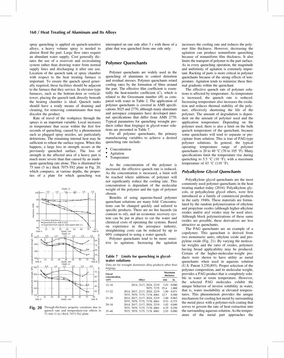
sprays is an important variable. Local increasesin temperature that occur within the first fewseconds of quenching, caused by a phenomenonsuch as plugged spray nozzles, are particularlydeleterious. The remaining internal heat may besufficient to reheat the surface region. When thishappens, a large loss in strength occurs at thepreviously quenched surface. The loss ofstrength in the affected area of a heavy part ismuch more severe than that caused by an inade-quate quenching rate alone. This is illustrated for75 mm (3 in.) thick 7075-T62 plate in Fig. 20,which compares, at various depths, the proper-ties of a plate for which quenching was
interrupted on one side after 3 s with those of aplate that was quenched from one side only.
Polymer Quenchants
Polymer quenchants are widely used in thequenching of aluminum to control distortionand residual stresses. Polymer quenchants retardcooling rates by the formation of films aroundthe part. The effective film coefficient is essen-tially the heat-transfer coefficient (C), which isrelated to the Grossmann number (H) as com-pared with water in Table 2. The application ofpolymer quenchants is covered in AMS specifi-cations 3025 and 2770, although many aluminumand aerospace companies have developed inter-nal specifications that differ from AMS 2770.Typical parameters for quenching wrought pro-ducts (other than forgings) in glycol-water solu-tions are presented in Table 7.For all polymer quenchants, the primary
manufacturing variables to achieve a desiredquenching rate include:
� Concentration� Agitation� Temperature
As the concentration of the polymer isincreased, the effective quench rate is reduced.As the concentration is increased, a limit willbe reached where additions of polymer willnot significantly reduce the cooling rate. Thisconcentration is dependant of the molecularweight of the polymer and the type of polymerchosen.Benefits of using aqueous-based polymer
quenchant solutions are many fold. Concentra-tions can be changed quickly and tailored tospecific products. There are no fire hazards (incontrast to oil), and an economic recovery sys-tem can be put in place to cut the water andchemical costs of operating the systems. Basedon experience in the aerospace industry,straightening costs can be reduced by up to60% compared to using a water quench.Polymer quenchants tend to be more sensi-
tive to agitation. Increasing the agitation
increases the cooling rate and reduces the poly-mer film thickness. However, decreasing theagitation can produce nonuniform quenchingbecause of nonuniform film thickness. It alsolimits the transport of polymer to the part surface.As in every quenching operation, the magnitudeand uniformity of agitation is extremely impor-tant. Racking of parts is more critical in polymerquenchants because of the strong effects of tem-perature. Agitation tends to minimize these ther-mal gradients within the quenchant.The effective quench rate of polymer solu-
tions is affected by temperature. As temperatureis increased, the quench rate is reduced.Increasing temperature also increases the oxida-tion and reduces thermal stability of the poly-mer, effectively shortening the life of thepolymer. The amount of degradation is depen-dent on the amount of polymer used and theapplication temperature. Depending on thepolymer used, there is also a limit on the bulkquench temperature of the quenchant, becausesome quenchants will tend to separate or pre-cipitate from solution. This is true of PAG-typepolymer solutions. In general, the typicaloperating temperature range of polymerquenchants is 20 to 40 �C (70 to 105 �F). Manyspecifications limit the temperature rise duringquenching to 5.5 �C (10 �F), with a maximumtemperature of 43 �C (110 �F).
Polyalkylene Glycol Quenchants
Polyalkylene glycol quenchants are the mostcommonly used polymer quenchants in the heattreating market today (2016). Polyalkylene gly-cols, or polyalkylene glycol ethers, were firstintroduced as a family of commercial productsin the early 1940s. These materials are formu-lated by the random polymerization of ethyleneand propylene oxides (although higher-alkyleneoxides and/or aryl oxides may be used also).Although block polymerizations of these sameoxides are possible, these derivatives are lessattractive as quenchants.The PAG quenchants are an example of a
copolymer. This quenchant is derived fromtwo monomeric units, ethylene oxide and pro-pylene oxide (Fig. 21). By varying the molecu-lar weights and the ratio of oxides, polymershaving broad applicability may be produced.Certain of the higher-molecular-weight pro-ducts were shown to have utility as metalquenchants when used in aqueous solution(U.S. Patent 3,230,893). Proper selection of thepolymer composition, and its molecular weight,provides a PAG product that is completely solu-ble in water at room temperature. However,the selected PAG molecules exhibit theunique behavior of inverse solubility in water,that is, water insolubility at elevated tempera-tures. This phenomenon provides the uniquemechanism for cooling hot metal by surroundingthe metal piece with a polymer-rich coating thatserves to govern the rate of heat extraction intothe surrounding aqueous solution. As the temper-ature of the metal part approaches the
1000 0.5 1.0 1.5Depth, in.
Depth, in.
Depth, in.
2.0 2.5 3.0
90
80
70
60
50
600
500
400
550
450
350
250
150
3000
Side A Side B10 20 30 40
Depth, mm
Long
itudi
nal t
ensi
le s
tren
gth,
MP
aLo
ngitu
dina
l yie
ld s
tren
gth,
MP
a
Long
itudi
nal t
ensi
le s
tren
gth,
ksi
Long
itudi
nal y
ield
str
engt
h, k
si
50 60 70 80
Side A Side BDepth, mm0 10 20 30 40 50 60 70 80
0
0 0.5 1.0 1.5 2.0 2.5 3.0
80
70
60
50
70
60
50
40
30
0 0.5 1.0 1.5 2.0 2.5 3.0
Side A10
Quenched from side A only
20 30
Har
dnes
s, H
RB
40Depth, mm Side B
50 60 70 80
Control specimen
Quenched from side B, interrupted after 3 s
Fig. 20 Through-thickness property variations due toquench rate and temperature-rise effects in75 mm (3 in.) thick 7075-T62 plate
Table 7 Limits for quenching in glycol-water solutionsData are for wrought aluminum alloy products other thanforgings.
Glycolconcentration,vol% Alloys
Maximumthickness
mm in.
12–16 2014, 2117, 2024, 2219 2.03 0.0807075, 7175 25.4 1.000
17–22 2014, 2017, 2117, 2024, 2219 1.80 0.0717075, 7079, 7175, 7178, 6061 12.7 0.500
23–28 2014, 2017, 2117, 2024, 2219 1.60 0.0637075, 7079, 7175, 7178, 6061 9.53 0.375
29–34 2014, 2017, 2117, 2024, 2219 1.02 0.0407075, 7079, 7175, 7178, 6061 6.35 0.250
35–40 7075, 7079, 7175, 7178, 6061 2.03 0.080
160 / Heat Treating of Aluminum and Its Alloys
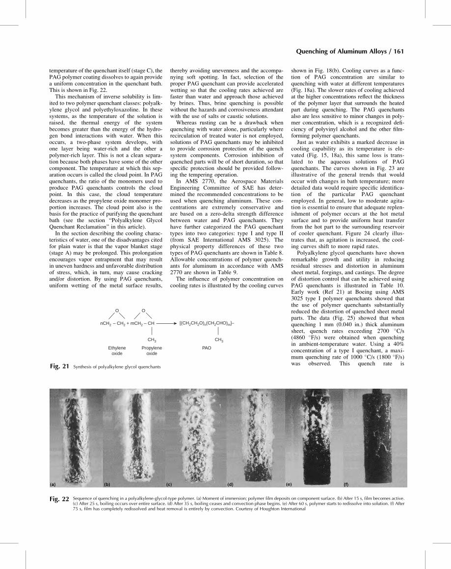
temperature of the quenchant itself (stage C), thePAG polymer coating dissolves to again providea uniform concentration in the quenchant bath.This is shown in Fig. 22.This mechanism of inverse solubility is lim-
ited to two polymer quenchant classes: polyalk-ylene glycol and polyethyloxazoline. In thesesystems, as the temperature of the solution israised, the thermal energy of the systembecomes greater than the energy of the hydro-gen bond interactions with water. When thisoccurs, a two-phase system develops, withone layer being water-rich and the other apolymer-rich layer. This is not a clean separa-tion because both phases have some of the othercomponent. The temperature at which this sep-aration occurs is called the cloud point. In PAGquenchants, the ratio of the monomers used toproduce PAG quenchants controls the cloudpoint. In this case, the cloud temperaturedecreases as the propylene oxide monomer pro-portion increases. The cloud point also is thebasis for the practice of purifying the quenchantbath (see the section “Polyalkylene GlycolQuenchant Reclamation” in this article).In the section describing the cooling charac-
teristics of water, one of the disadvantages citedfor plain water is that the vapor blanket stage(stage A) may be prolonged. This prolongationencourages vapor entrapment that may resultin uneven hardness and unfavorable distributionof stress, which, in turn, may cause crackingand/or distortion. By using PAG quenchants,uniform wetting of the metal surface results,
thereby avoiding unevenness and the accompa-nying soft spotting. In fact, selection of theproper PAG quenchant can provide acceleratedwetting so that the cooling rates achieved arefaster than water and approach those achievedby brines. Thus, brine quenching is possiblewithout the hazards and corrosiveness attendantwith the use of salts or caustic solutions.Whereas rusting can be a drawback when
quenching with water alone, particularly whererecirculation of treated water is not employed,solutions of PAG quenchants may be inhibitedto provide corrosion protection of the quenchsystem components. Corrosion inhibition ofquenched parts will be of short duration, so thatspecific protection should be provided follow-ing the tempering operation.In AMS 2770, the Aerospace Materials
Engineering Committee of SAE has deter-mined the recommended concentrations to beused when quenching aluminum. These con-centrations are extremely conservative andare based on a zero-delta strength differencebetween water and PAG quenchants. Theyhave further categorized the PAG quenchanttypes into two categories: type I and type II(from SAE International AMS 3025). Thephysical property differences of these twotypes of PAG quenchants are shown in Table 8.Allowable concentrations of polymer quench-ants for aluminum in accordance with AMS2770 are shown in Table 9.The influence of polymer concentration on
cooling rates is illustrated by the cooling curves
shown in Fig. 18(b). Cooling curves as a func-tion of PAG concentration are similar toquenching with water at different temperatures(Fig. 18a). The slower rates of cooling achievedat the higher concentrations reflect the thicknessof the polymer layer that surrounds the heatedpart during quenching. The PAG quenchantsalso are less sensitive to minor changes in poly-mer concentration, which is a recognized defi-ciency of polyvinyl alcohol and the other film-forming polymer quenchants.Just as water exhibits a marked decrease in
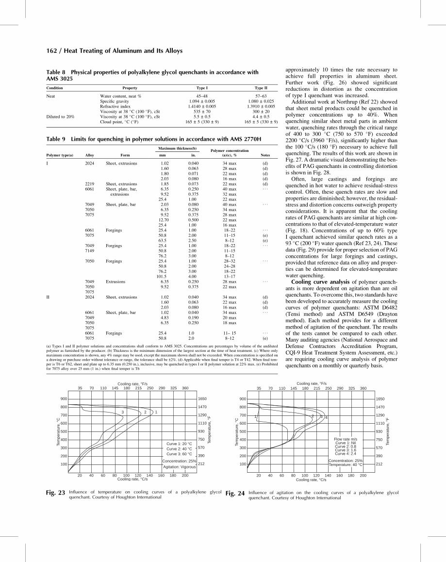
cooling capability as its temperature is ele-vated (Fig. 15, 18a), this same loss is trans-lated to the aqueous solutions of PAGquenchants. The curves shown in Fig. 23 areillustrative of the general trends that wouldoccur with changes in bath temperature; moredetailed data would require specific identifica-tion of the particular PAG quenchantemployed. In general, low to moderate agita-tion is essential to ensure that adequate replen-ishment of polymer occurs at the hot metalsurface and to provide uniform heat transferfrom the hot part to the surrounding reservoirof cooler quenchant. Figure 24 clearly illus-trates that, as agitation is increased, the cool-ing curves shift to more rapid rates.Polyalkylene glycol quenchants have shown
remarkable growth and utility in reducingresidual stresses and distortion in aluminumsheet metal, forgings, and castings. The degreeof distortion control that can be achieved usingPAG quenchants is illustrated in Table 10.Early work (Ref 21) at Boeing using AMS3025 type I polymer quenchants showed thatthe use of polymer quenchants substantiallyreduced the distortion of quenched sheet metalparts. The data (Fig. 25) showed that whenquenching 1 mm (0.040 in.) thick aluminumsheet, quench rates exceeding 2700 �C/s(4860 �F/s) were obtained when quenchingin ambient-temperature water. Using a 40%concentration of a type I quenchant, a maxi-mum quenching rate of 1000 �C/s (1800 �F/s)was observed. This quench rate is
Fig. 22 Sequence of quenching in a polyalkylene-glycol-type polymer. (a) Moment of immersion; polymer film deposits on component surface. (b) After 15 s, film becomes active.(c) After 25 s, boiling occurs over entire surface. (d) After 35 s, boiling ceases and convection phase begins. (e) After 60 s, polymer starts to redissolve into solution. (f) After75 s, film has completely redissolved and heat removal is entirely by convection. Courtesy of Houghton International
nCH2 – CH2 + mCH2 – CH
Ethyleneoxide
Propyleneoxide
PAO
O
CH3 CH3
[(CH2CH2O)n(CH2CHO)m]–
O
Fig. 21 Synthesis of polyalkylene glycol quenchants
Quenching of Aluminum Alloys / 161
approximately 10 times the rate necessary toachieve full properties in aluminum sheet.Further work (Fig. 26) showed significantreductions in distortion as the concentrationof type I quenchant was increased.Additional work at Northrup (Ref 22) showed
that sheet metal products could be quenched inpolymer concentrations up to 40%. Whenquenching similar sheet metal parts in ambientwater, quenching rates through the critical rangeof 400 to 300 �C (750 to 570 �F) exceeded2200 �C/s (3960 �F/s), significantly higher thanthe 100 �C/s (180 �F) necessary to achieve fullquenching. The results of this work are shown inFig. 27. A dramatic visual demonstrating the ben-efits of PAG quenchants in controlling distortionis shown in Fig. 28.Often, large castings and forgings are
quenched in hot water to achieve residual-stresscontrol. Often, these quench rates are slow andproperties are diminished; however, the residual-stress and distortion concerns outweigh propertyconsiderations. It is apparent that the coolingrates of PAG quenchants are similar at high con-centrations to that of elevated-temperature water(Fig. 18). Concentrations of up to 60% typeI quenchant achieved similar quench rates as a93 �C (200 �F) water quench (Ref 23, 24). Thesedata (Fig. 29) provide for proper selection of PAGconcentrations for large forgings and castings,provided that reference data on alloy and proper-ties can be determined for elevated-temperaturewater quenching.Cooling curve analysis of polymer quench-
ants is more dependent on agitation than are oilquenchants. To overcome this, two standards havebeen developed to accurately measure the coolingcurves of polymer quenchants: ASTM D6482(Tensi method) and ASTM D6549 (Draytonmethod). Each method provides for a differentmethod of agitation of the quenchant. The resultsof the tests cannot be compared to each other.Many auditing agencies (National Aerospace andDefense Contractors Accreditation Program,CQI-9 Heat Treatment System Assessment, etc.)are requiring cooling curve analysis of polymerquenchants on a monthly or quarterly basis.
Table 9 Limits for quenching in polymer solutions in accordance with AMS 2770H
Polymer type(a) Alloy Form
Maximum thickness(b)Polymer concentration
(a)(c), % Notesmm in.
I 2024 Sheet, extrusions 1.02 0.040 34 max (d)1.60 0.063 28 max (d)1.80 0.071 22 max (d)2.03 0.080 16 max (d)
2219 Sheet, extrusions 1.85 0.073 22 max (d)6061 Sheet, plate, bar,
extrusions6.35 0.250 40 max . . .
9.52 0.375 32 max25.4 1.00 22 max
704970507075
Sheet, plate, bar 2.03 0.080 40 max . . .
6.35 0.250 34 max9.52 0.375 28 max
12.70 0.500 22 max25.4 1.00 16 max
60617075
Forgings 25.4 1.00 18–22 . . .
50.8 2.00 11–15 (e)63.5 2.50 8–12 (e)
70497149
Forgings 25.4 1.00 18–22 . . .
50.8 2.00 11–1576.2 3.00 8–12
7050 Forgings 25.4 1.00 28–32 . . .
50.8 2.00 24–2876.2 3.00 18–22101.5 4.00 13–17
704970507075
Extrusions 6.35 0.250 28 max . . .
9.52 0.375 22 max
II 2024 Sheet, extrusions 1.02 0.040 34 max (d)1.60 0.063 22 max (d)2.03 0.080 16 max (d)
6061704970507075
Sheet, plate, bar 1.02 0.040 34 max . . .
4.83 0.190 20 max6.35 0.250 18 max
60617075
Forgings 25.4 1.0 11– 15 . . .
50.8 2.0 8–12 (e)
(a) Types I and II polymer solutions and concentrations shall conform to AMS 3025. Concentrations are percentages by volume of the undilutedpolymer as furnished by the producer. (b) Thickness is the minimum dimension of the largest section at the time of heat treatment. (c) Where onlymaximum concentration is shown, any 4% range may be used, except the maximum shown shall not be exceeded. When concentration is specified ona drawing or purchase order without tolerance or range, the tolerance shall be ±2%. (d) Applicable when final temper is T4 or T42. When final tem-per is T6 or T62, sheet and plate up to 6.35 mm (0.250 in.), inclusive, may be quenched in types I or II polymer solution at 22% max. (e) Prohibitedfor 7075 alloy over 25 mm (1 in.) when final temper is T6
Table 8 Physical properties of polyalkylene glycol quenchants in accordance withAMS 3025
Condition Property Type I Type II
Neat Water content, neat % 45–48 57–63Specific gravity 1.094 ± 0.005 1.080 ± 0.025Refractive index 1.4140 ± 0.005 1.3910 ± 0.005Viscosity at 38 �C (100 �F), cSt 535 ± 70 300 ± 20
Diluted to 20% Viscosity at 38 �C (100 �F), cSt 5.5 ± 0.5 4.4 ± 0.5Cloud point, �C (�F) 165 ± 5 (330 ± 9) 165 ± 5 (330 ± 9)
900
800
700
600
500
400
300
200
100
Cooling rate, °C/s
Cooling rate, °F/s
20 40 60 80 100 120 140 160 180 200
Curve 2: 0.8
Flow rate m/s
Curve 3: 1.6Curve 4: 2.4
Curve 1: Nil
Concentration: 25%Temperature: 40 °C 212
390
570
750
930
1110
1290
1470
1650
1 2 3 4
35 70 110 145 180 215 250 290 325 360Te
mpe
ratu
re, °
F
Tem
pera
ture
, °C
Fig. 24 Influence of agitation on the cooling curves of a polyalkylene glycolquenchant. Courtesy of Houghton International
900
800
700
600
500
400
300
200
100
Cooling rate, °C/s
Cooling rate, °F/s
20 40 60 80 100 120 140 160 180 200
212
390
570Curve 1: 20 °CCurve 2: 40 °CCurve 3: 60 °C
Concentration: 25%
Agitation: Vigorous
750
930
1110
1290
1470
1650
123
35 70 110 145 180 215 250 290 325 360
Tem
pera
ture
, °F
Tem
pera
ture
, °C
Fig. 23 Influence of temperature on cooling curves of a polyalkylene glycolquenchant. Courtesy of Houghton International
162 / Heat Treating of Aluminum and Its Alloys
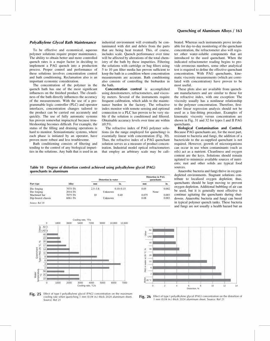
Polyalkylene Glycol Bath Maintenance
To be effective and economical, aqueouspolymer solutions require proper maintenance.The ability to obtain better and more controlledquench rates is a major factor in deciding toimplement a PAG quench into a productionprocess. Proper control and performance ofthese solutions involves concentration controland bath conditioning. Reclamation also is animportant economic consideration.The concentration of the polymer in the
quench bath has one of the most significantinfluences on the finished product. The cleanli-ness of the bath directly influences the accuracyof the measurements. With the use of a pro-grammable logic controller (PLC) and operatorinterfaces, concentration changes tailored tothe product can be carried out accurately andquickly. The use of fully automatic systemshas proven somewhat impractical because trou-bleshooting becomes difficult. For example, thestatus of the filling and draining operations ishard to monitor. Semiautomatic systems, whereeach phase is initiated by an operator, haveproven more robust and less troublesome.Bath conditioning consists of filtering and
tending to the control of any biological impuri-ties in the solutions. Any bath that is used in an
industrial environment will eventually be con-taminated with dirt and debris from the partsthat are being heat treated. This, of course,includes scale. Quench performance over timewill be affected by alterations of the total chem-istry of the bath by these impurities. Filteringthe solutions with cartridge or bag filters using5 to 10 mm filter media has proven sufficient tokeep the bath in a condition where concentrationmeasurements are accurate. Bath conditioningalso consists of controlling the bioburden inthe bath.Concentration control is accomplished
using densitometers, refractometers, and viscos-ity meters. Several of the instruments requirefrequent calibration, which adds to the mainte-nance burden in the factory. The refractiveindex monitor with remote sensing and optionalconnection to a PLC has proven to be very sta-ble if the solution is conditioned and filtered.Obtainable accuracy levels over time are within±0.5%.The refractive index of PAG polymer solu-
tions (in the range employed for quenching) isessentially linear with concentration (Fig. 30).Thus, the refractive index of a PAG quenchantsolution serves as a measure of product concen-tration. Industrial model optical refractometersthat employ an arbitrary scale may be cali-
brated. Whereas such instruments prove invalu-able for day-to-day monitoring of the quenchantconcentration, the refractometer also will regis-ter other water-soluble components that areintroduced to the used quenchant. When theindicated refractometer reading begins to pro-vide erroneous numbers, some other analyticaltest is required to define the effective quenchantconcentration. With PAG quenchants, kine-matic viscosity measurements (which are corre-lated with concentration) have proven to bemost useful.These plots also are available from quench-
ant manufacturers and are similar to those forthe refractive index, with one exception: Theviscosity usually has a nonlinear relationshipto the polymer concentration. Therefore, first-order linear regression analysis should not beused as a line-fitting procedure. Examples ofkinematic viscosity versus concentration areshown in Fig. 31 and 32 for types I and II PAGquenchants.Biological Contamination and Control.
Because PAG quenchants are, for the most part,resistant to bacteria and fungi, the addition of abactericide to the as-supplied quenchant is notrequired. However, growth of microorganismscan occur in use when contaminants (such asoils) act as a nutrient. Cleanliness and oxygencontent are the keys. Solutions should remainagitated to minimize available sources of nutri-ents; rust and other solids are typical foodsources.Anaerobic bacteria and fungi thrive in oxygen-
depleted environments. Stagnant solutions con-tribute to localized oxygen depletion; thus,quenchants should be kept moving to preventoxygen depletion. Additional bubbling of air canbe used, but it is generally most effective tocontinue agitating the quenchants during shut-downs. Anaerobic bacteria and fungi can breedin typical polymer quench tanks. These bacteriaand fungi are not usually a health hazard but an
Table 10 Degree of distortion control achieved using polyalkylene glycol (PAG)quenchants in aluminum
Part type Alloy
Distortion in waterDistortion in PAG
quenchants
mm in. mm in.
Die forging 7075-T6 2.5–3.8 0.10–0.15 0.05 0.002Die forging 2014-T6 Unknown NoneMachined bar 7075-T6 10 0.40 0.075 0.003Dip-brazed chassis 6061-T6 Unknown 0.08 0.003
Source: Ref 20
Air
Oth
erQ
uenc
hant
LN2
40
22
20
17
14
11
8
6
4
2
56
25
0 1000 2000 3000 4000 5000 6000 7000
10
Cooling rate, °F/s
Cooling rate, °C/s
Type
I P
AG
26
°C, %
Wat
erte
mpe
ratu
re,
°C
0 1800 3600 5400 7200 9000 10,800 12,600
Fig. 25 Effect of type I polyalkylene glycol (PAG) concentration on the maximumcooling rate when quenching 1 mm (0.04 in.) thick 2024 aluminum sheet.Source: Ref 21
Air
Oth
er
LN2
40
30
20
11
6
2
0 2 4 6 8 10 12 14Distortion, %
PAG
in w
ate
r a
t 26
°C, %
26 °C
Wa
ter
Fig. 26 Effect of type I polyalkylene glycol (PAG) concentration on the distortion of1 mm (0.04 in.) thick 2024 aluminum sheet. Source: Ref 21
Quenching of Aluminum Alloys / 163
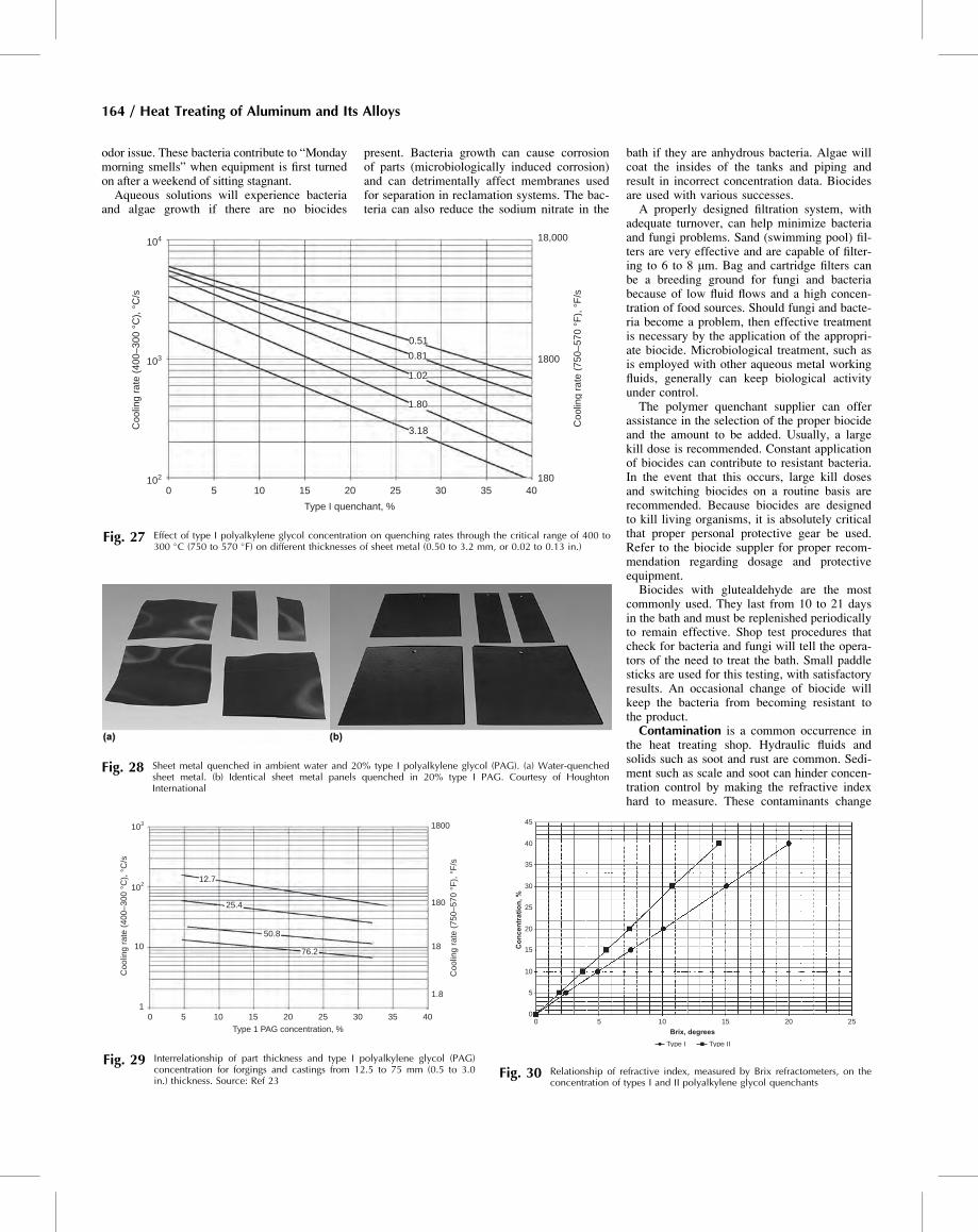
odor issue. These bacteria contribute to “Mondaymorning smells” when equipment is first turnedon after a weekend of sitting stagnant.Aqueous solutions will experience bacteria
and algae growth if there are no biocides
present. Bacteria growth can cause corrosionof parts (microbiologically induced corrosion)and can detrimentally affect membranes usedfor separation in reclamation systems. The bac-teria can also reduce the sodium nitrate in the
bath if they are anhydrous bacteria. Algae willcoat the insides of the tanks and piping andresult in incorrect concentration data. Biocidesare used with various successes.A properly designed filtration system, with
adequate turnover, can help minimize bacteriaand fungi problems. Sand (swimming pool) fil-ters are very effective and are capable of filter-ing to 6 to 8 mm. Bag and cartridge filters canbe a breeding ground for fungi and bacteriabecause of low fluid flows and a high concen-tration of food sources. Should fungi and bacte-ria become a problem, then effective treatmentis necessary by the application of the appropri-ate biocide. Microbiological treatment, such asis employed with other aqueous metal workingfluids, generally can keep biological activityunder control.The polymer quenchant supplier can offer
assistance in the selection of the proper biocideand the amount to be added. Usually, a largekill dose is recommended. Constant applicationof biocides can contribute to resistant bacteria.In the event that this occurs, large kill dosesand switching biocides on a routine basis arerecommended. Because biocides are designedto kill living organisms, it is absolutely criticalthat proper personal protective gear be used.Refer to the biocide suppler for proper recom-mendation regarding dosage and protectiveequipment.Biocides with glutealdehyde are the most
commonly used. They last from 10 to 21 daysin the bath and must be replenished periodicallyto remain effective. Shop test procedures thatcheck for bacteria and fungi will tell the opera-tors of the need to treat the bath. Small paddlesticks are used for this testing, with satisfactoryresults. An occasional change of biocide willkeep the bacteria from becoming resistant tothe product.Contamination is a common occurrence in
the heat treating shop. Hydraulic fluids andsolids such as soot and rust are common. Sedi-ment such as scale and soot can hinder concen-tration control by making the refractive indexhard to measure. These contaminants change
0.51
0.81
1.02
1.80
3.18
Type I quenchant, %
Coo
ling
rate
(40
0–30
0 °C
), °
C/s
Coo
ling
rate
(75
0–57
0 °F
), °
F/s
0 5 10 15 20 25 30 35 40180
1800
18,000104
102
103
Fig. 27 Effect of type I polyalkylene glycol concentration on quenching rates through the critical range of 400 to300 �C (750 to 570 �F) on different thicknesses of sheet metal (0.50 to 3.2 mm, or 0.02 to 0.13 in.)
Fig. 28 Sheet metal quenched in ambient water and 20% type I polyalkylene glycol (PAG). (a) Water-quenchedsheet metal. (b) Identical sheet metal panels quenched in 20% type I PAG. Courtesy of HoughtonInternational
Type 1 PAG concentration, %
Coo
ling
rate
(40
0–30
0 °C
), °
C/s
Coo
ling
rate
(75
0–57
0 °F
), °
F/s
50 10 15 20 25 30 35 40
1.8
18
180
1800103
10
1
102
76.2
50.8
25.4
12.7
Fig. 29 Interrelationship of part thickness and type I polyalkylene glycol (PAG)concentration for forgings and castings from 12.5 to 75 mm (0.5 to 3.0in.) thickness. Source: Ref 23
45
40
35
30
25
20
15
10
5
00 5 10 15 20 25
Brix, degrees
Co
nce
ntr
atio
n, %
Type I Type II
Fig. 30 Relationship of refractive index, measured by Brix refractometers, on theconcentration of types I and II polyalkylene glycol quenchants
164 / Heat Treating of Aluminum and Its Alloys
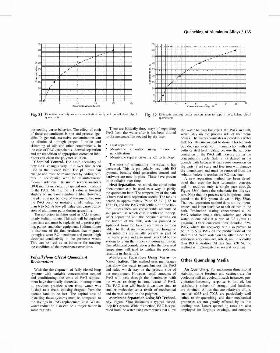
the cooling curve behavior. The effect of eachof these contaminants is site and process spe-cific. In general, excessive contamination canbe eliminated through proper filtration andskimming of oils and other contaminants. Inthe case of PAG quenchants, thermal separationand the readdition of appropriate corrosion inhi-bitors can clean the polymer solution.Chemical Control. The basic chemistry of
new PAG changes very little over time whenused in the quench bath. The pH level canchange and must be maintained by adding buf-fers in accordance with the manufacturers’recommendations. The use of reverse osmosis(RO) membranes requires special modificationsto the PAG. Mainly, the pH value is loweredslightly to increase membrane life. However,the pH must not be lowered too much, becausethe PAG becomes unstable at pH values lessthan 6 to 6.5. A low pH value can cause corro-sion of aluminum parts during quenching.The corrosion inhibitor used in PAG is com-
monly sodium nitrate. This salt will be depletedover time and must be replenished to protect pip-ing, pumps, and other equipment. Sodium nitrateis also one of the first products that migratesthrough a worn RO membrane and creates highelectrical conductivity in the permeate water.This can be used as an indicator for trackingthe condition of the membranes over time.
Polyalkylene Glycol QuenchantReclamation
With the development of fully closed loopsystems with variable concentration controland conditioning, the costs of PAG replace-ment have drastically decreased in comparisonto previous practice when rinse water wasflushed to a drain, causing dragout from thequench tank to be lost. The capital cost ofinstalling these systems must be compared tothe savings in PAG replacement cost. Waste-water reduction also can be a major factor insome regions.
There are basically three ways of separatingPAG from the water after it has been dilutedto the concentration needed by the user:
� Heat separation� Membrane separation using micro- or
nanofiltration� Membrane separation using RO technology
The cost of maintaining the systems hasdecreased. This is particularly true with ROsystems, because third-generation control andhardware are now in place. These have provento be reliable over time.Heat Separation. As noted, the cloud point
phenomenon can be used as a way to purifythe quenchant bath. The temperature of the bathis increased until separation occurs. The tank isheated to approximately 75 to 85 �C (165 to185 �F), and the PAG will settle out to the bot-tom, unless there are considerable amounts ofsalt present, in which case it settles to the top.After separation and the polymer settling onthe bottom of the tank, water is pumped orsiphoned from the tank. Fresh water is thenadded to the desired concentration. Inorganicrust inhibitors are usually present as part ofthe water phase and also must be added to thesystem to retain the proper corrosion inhibition.One additional consideration is that the increasedtemperature will tend to oxidize the polymer,resulting in shorter life.Membrane Separation Using Micro- or
Nanofiltration. This method uses membranesthat allow the water to pass but not the PAGand salts, which stay on the process side ofthe membranes. However, small amounts ofPAG will pass through the membranes withthe water, resulting in some waste of PAG.The PAG also will break down over time tosmaller molecules as a result of mechanicaland thermal action on the polymer.Membrane Separation Using RO Technol-
ogy. Figure 33(a) illustrates a typical closed-loop RO system. With this method, PAG is sepa-rated from the water using membranes that allow
the water to pass but reject the PAG and salt,which stay on the process side of the mem-branes. The water (permeate) is stored in a watertank for later use or sent to drain. This technol-ogy does not work well in conjunction with saltbaths or steel heat treating because the salt con-centration in the PAG will increase during theconcentration cycle. Salt is not desired in thequench bath because it can cause corrosion onthe parts. Steel scale and free iron will damagethe membranes and must be removed from thesolution before it reaches the RO machine.A new separation method has been devel-
oped that uses the heat separation concept,and it requires only a single pass-through.Figure 33(b) shows the schematic for this sys-tem. Note that the process tank is optional com-pared to the RO system shown in Fig. 33(a).The heat separation method does not use mem-branes and is not sensitive to salt or iron in thebath. Production testing concentrated a 1%PAG solution into a 60% solution and cleanwater in one pass at a rate of 3.8 L/min (1gal/min). Other concentrations included 22%PAG, where the recovery rate also proved tobe up to 60% PAG on the product side of thestream and clean water on the other side. Thesystem is very compact, robust, and less costlythan RO separation. At this time (2016), themethod is implemented in several locations.
Other Quenching Media
Air Quenching. For maximum dimensionalstability, some forgings and castings are fancooled or still-air cooled. In such instances, pre-cipitation-hardening response is limited, butsatisfactory values of strength and hardnessare obtained. Alloys that are relatively dilute,such as 6063 and 7005, are particularly wellsuited to air quenching, and their mechanicalproperties are not greatly affected by its lowcooling rate. Lower quenching rates are alsoemployed for forgings, castings, and complex
45
40
35
30
25
20
15
10
5
00 5 10 15 20 25
Kinematic viscosity, cSt
Co
nce
ntr
atio
n, %
Fig. 31 Kinematic viscosity versus concentration for type I polyalkylene glycolquenchants
45
40
35
30
25
20
15
10
5
00 2 4 6 8 10 12 1814 16
Kinematic viscosity, cSt
Co
nce
ntr
atio
n, %
Fig. 32 Kinematic viscosity versus concentration for type II polyalkylene glycolquenchants
Quenching of Aluminum Alloys / 165
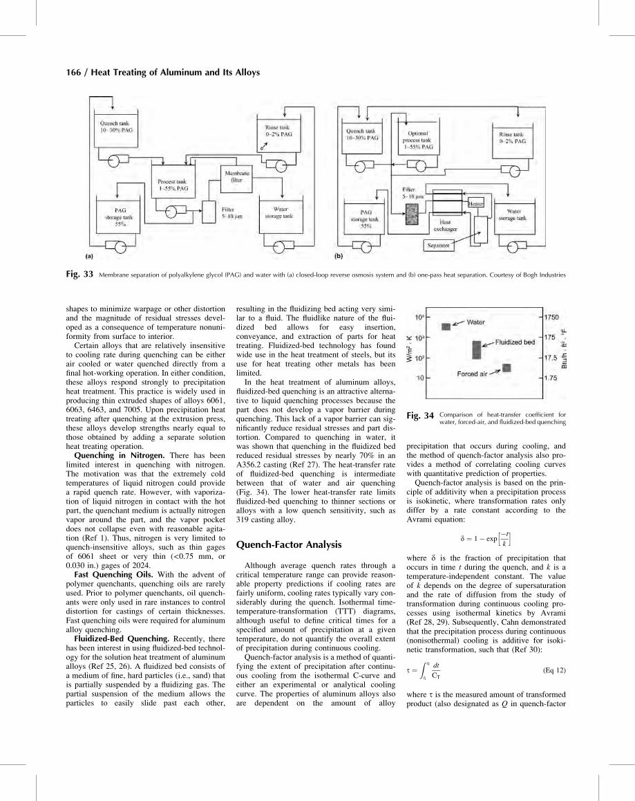
shapes to minimize warpage or other distortionand the magnitude of residual stresses devel-oped as a consequence of temperature nonuni-formity from surface to interior.Certain alloys that are relatively insensitive
to cooling rate during quenching can be eitherair cooled or water quenched directly from afinal hot-working operation. In either condition,these alloys respond strongly to precipitationheat treatment. This practice is widely used inproducing thin extruded shapes of alloys 6061,6063, 6463, and 7005. Upon precipitation heattreating after quenching at the extrusion press,these alloys develop strengths nearly equal tothose obtained by adding a separate solutionheat treating operation.Quenching in Nitrogen. There has been
limited interest in quenching with nitrogen.The motivation was that the extremely coldtemperatures of liquid nitrogen could providea rapid quench rate. However, with vaporiza-tion of liquid nitrogen in contact with the hotpart, the quenchant medium is actually nitrogenvapor around the part, and the vapor pocketdoes not collapse even with reasonable agita-tion (Ref 1). Thus, nitrogen is very limited toquench-insensitive alloys, such as thin gagesof 6061 sheet or very thin (<0.75 mm, or0.030 in.) gages of 2024.Fast Quenching Oils. With the advent of
polymer quenchants, quenching oils are rarelyused. Prior to polymer quenchants, oil quench-ants were only used in rare instances to controldistortion for castings of certain thicknesses.Fast quenching oils were required for aluminumalloy quenching.Fluidized-Bed Quenching. Recently, there
has been interest in using fluidized-bed technol-ogy for the solution heat treatment of aluminumalloys (Ref 25, 26). A fluidized bed consists ofa medium of fine, hard particles (i.e., sand) thatis partially suspended by a fluidizing gas. Thepartial suspension of the medium allows theparticles to easily slide past each other,
resulting in the fluidizing bed acting very simi-lar to a fluid. The fluidlike nature of the flui-dized bed allows for easy insertion,conveyance, and extraction of parts for heattreating. Fluidized-bed technology has foundwide use in the heat treatment of steels, but itsuse for heat treating other metals has beenlimited.In the heat treatment of aluminum alloys,
fluidized-bed quenching is an attractive alterna-tive to liquid quenching processes because thepart does not develop a vapor barrier duringquenching. This lack of a vapor barrier can sig-nificantly reduce residual stresses and part dis-tortion. Compared to quenching in water, itwas shown that quenching in the fluidized bedreduced residual stresses by nearly 70% in anA356.2 casting (Ref 27). The heat-transfer rateof fluidized-bed quenching is intermediatebetween that of water and air quenching(Fig. 34). The lower heat-transfer rate limitsfluidized-bed quenching to thinner sections oralloys with a low quench sensitivity, such as319 casting alloy.
Quench-Factor Analysis
Although average quench rates through acritical temperature range can provide reason-able property predictions if cooling rates arefairly uniform, cooling rates typically vary con-siderably during the quench. Isothermal time-temperature-transformation (TTT) diagrams,although useful to define critical times for aspecified amount of precipitation at a giventemperature, do not quantify the overall extentof precipitation during continuous cooling.Quench-factor analysis is a method of quanti-
fying the extent of precipitation after continu-ous cooling from the isothermal C-curve andeither an experimental or analytical coolingcurve. The properties of aluminum alloys alsoare dependent on the amount of alloy
precipitation that occurs during cooling, andthe method of quench-factor analysis also pro-vides a method of correlating cooling curveswith quantitative prediction of properties.Quench-factor analysis is based on the prin-
ciple of additivity when a precipitation processis isokinetic, where transformation rates onlydiffer by a rate constant according to theAvrami equation:
d ¼ 1� exp�t
k
h i
where d is the fraction of precipitation thatoccurs in time t during the quench, and k is atemperature-independent constant. The valueof k depends on the degree of supersaturationand the rate of diffusion from the study oftransformation during continuous cooling pro-cesses using isothermal kinetics by Avrami(Ref 28, 29). Subsequently, Cahn demonstratedthat the precipitation process during continuous(nonisothermal) cooling is additive for isoki-netic transformation, such that (Ref 30):
t ¼Z tf
ti
dt
CT
(Eq 12)
where t is the measured amount of transformedproduct (also designated as Q in quench-factor
Fig. 33 Membrane separation of polyalkylene glycol (PAG) and water with (a) closed-loop reverse osmosis system and (b) one-pass heat separation. Courtesy of Bogh Industries
Fig. 34 Comparison of heat-transfer coefficient forwater, forced-air, and fluidized-bed quenching
166 / Heat Treating of Aluminum and Its Alloys
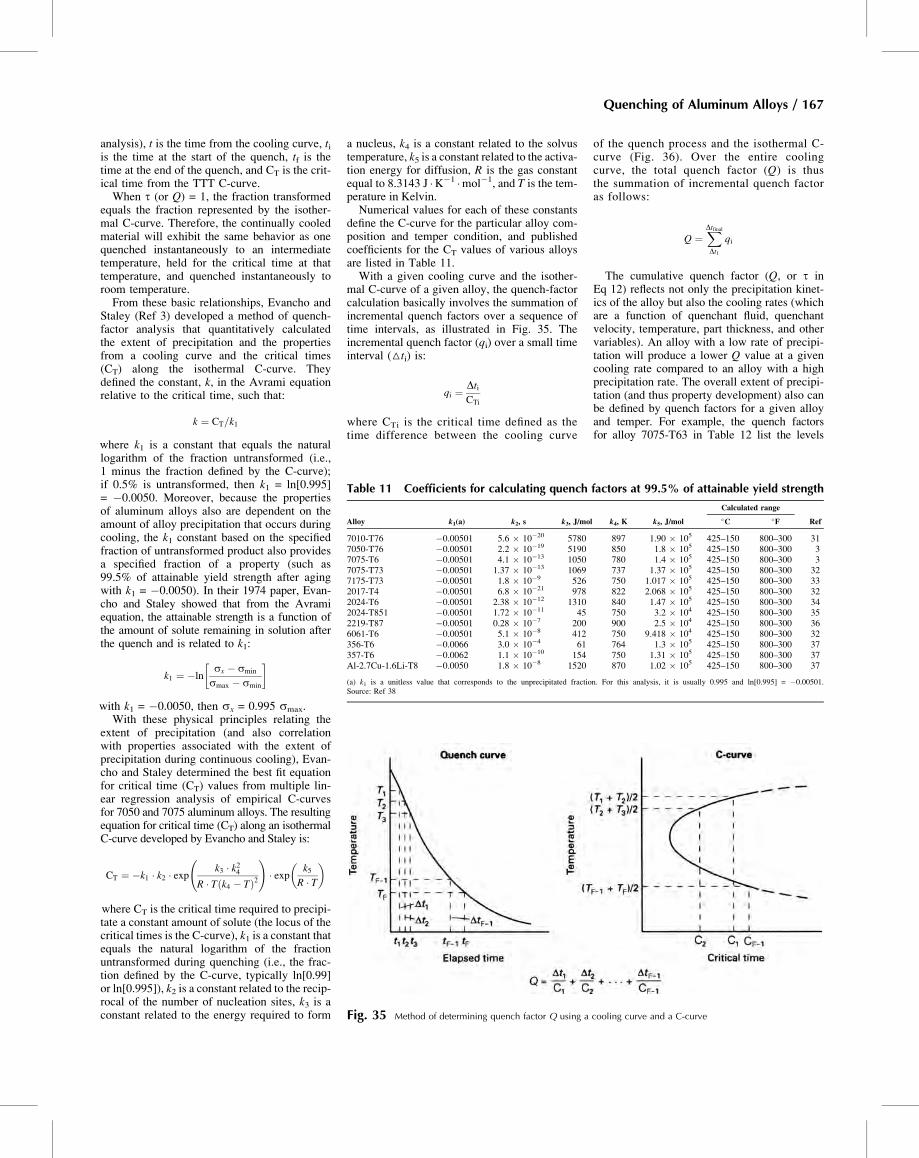
analysis), t is the time from the cooling curve, tiis the time at the start of the quench, tf is thetime at the end of the quench, and CT is the crit-ical time from the TTT C-curve.When t (or Q) = 1, the fraction transformed
equals the fraction represented by the isother-mal C-curve. Therefore, the continually cooledmaterial will exhibit the same behavior as onequenched instantaneously to an intermediatetemperature, held for the critical time at thattemperature, and quenched instantaneously toroom temperature.From these basic relationships, Evancho and
Staley (Ref 3) developed a method of quench-factor analysis that quantitatively calculatedthe extent of precipitation and the propertiesfrom a cooling curve and the critical times(CT) along the isothermal C-curve. Theydefined the constant, k, in the Avrami equationrelative to the critical time, such that:
k ¼ CT=k1
where k1 is a constant that equals the naturallogarithm of the fraction untransformed (i.e.,1 minus the fraction defined by the C-curve);if 0.5% is untransformed, then k1 = ln[0.995]= �0.0050. Moreover, because the propertiesof aluminum alloys also are dependent on theamount of alloy precipitation that occurs duringcooling, the k1 constant based on the specifiedfraction of untransformed product also providesa specified fraction of a property (such as99.5% of attainable yield strength after agingwith k1 = �0.0050). In their 1974 paper, Evan-cho and Staley showed that from the Avramiequation, the attainable strength is a function ofthe amount of solute remaining in solution afterthe quench and is related to k1:
k1 ¼ �lnsx � smin
smax � smin
� �
with k1 = �0.0050, then sx = 0.995 smax.With these physical principles relating the
extent of precipitation (and also correlationwith properties associated with the extent ofprecipitation during continuous cooling), Evan-cho and Staley determined the best fit equationfor critical time (CT) values from multiple lin-ear regression analysis of empirical C-curvesfor 7050 and 7075 aluminum alloys. The resultingequation for critical time (CT) along an isothermalC-curve developed by Evancho and Staley is:
CT ¼ �k1 � k2 � exp k3 � k24R � T k4 � Tð Þ2 !
� exp k5R � T� �
where CT is the critical time required to precipi-tate a constant amount of solute (the locus of thecritical times is the C-curve), k1 is a constant thatequals the natural logarithm of the fractionuntransformed during quenching (i.e., the frac-tion defined by the C-curve, typically ln[0.99]or ln[0.995]), k2 is a constant related to the recip-rocal of the number of nucleation sites, k3 is aconstant related to the energy required to form
a nucleus, k4 is a constant related to the solvustemperature, k5 is a constant related to the activa-tion energy for diffusion, R is the gas constantequal to 8.3143 J �K�1 �mol�1, and T is the tem-perature in Kelvin.Numerical values for each of these constants
define the C-curve for the particular alloy com-position and temper condition, and publishedcoefficients for the CT values of various alloysare listed in Table 11.With a given cooling curve and the isother-
mal C-curve of a given alloy, the quench-factorcalculation basically involves the summation ofincremental quench factors over a sequence oftime intervals, as illustrated in Fig. 35. Theincremental quench factor (qi) over a small timeinterval (△ti) is:
qi ¼ DtiCTi
where CTi is the critical time defined as thetime difference between the cooling curve
of the quench process and the isothermal C-curve (Fig. 36). Over the entire coolingcurve, the total quench factor (Q) is thusthe summation of incremental quench factoras follows:
Q ¼XDtfinalDt1
qi
The cumulative quench factor (Q, or t inEq 12) reflects not only the precipitation kinet-ics of the alloy but also the cooling rates (whichare a function of quenchant fluid, quenchantvelocity, temperature, part thickness, and othervariables). An alloy with a low rate of precipi-tation will produce a lower Q value at a givencooling rate compared to an alloy with a highprecipitation rate. The overall extent of precipi-tation (and thus property development) also canbe defined by quench factors for a given alloyand temper. For example, the quench factorsfor alloy 7075-T63 in Table 12 list the levels
Fig. 35 Method of determining quench factor Q using a cooling curve and a C-curve
Table 11 Coefficients for calculating quench factors at 99.5% of attainable yield strength
Alloy k1(a) k2, s k3, J/mol k4, K k5, J/mol
Calculated range
Ref�C �F
7010-T76 �0.00501 5.6 � 10�20 5780 897 1.90 � 105 425–150 800–300 317050-T76 �0.00501 2.2 � 10�19 5190 850 1.8 � 105 425–150 800–300 37075-T6 �0.00501 4.1 � 10�13 1050 780 1.4 � 105 425–150 800–300 37075-T73 �0.00501 1.37 � 10�13 1069 737 1.37 � 105 425–150 800–300 327175-T73 �0.00501 1.8 � 10�9 526 750 1.017 � 105 425–150 800–300 332017-T4 �0.00501 6.8 � 10�21 978 822 2.068 � 105 425–150 800–300 322024-T6 �0.00501 2.38 � 10�12 1310 840 1.47 � 105 425–150 800–300 342024-T851 �0.00501 1.72 � 10�11 45 750 3.2 � 104 425–150 800–300 352219-T87 �0.00501 0.28 � 10�7 200 900 2.5 � 104 425–150 800–300 366061-T6 �0.00501 5.1 � 10�8 412 750 9.418 � 104 425–150 800–300 32356-T6 �0.0066 3.0 � 10�4 61 764 1.3 � 105 425–150 800–300 37357-T6 �0.0062 1.1 � 10�10 154 750 1.31 � 105 425–150 800–300 37Al-2.7Cu-1.6Li-T8 �0.0050 1.8 � 10�8 1520 870 1.02 � 105 425–150 800–300 37
(a) k1 is a unitless value that corresponds to the unprecipitated fraction. For this analysis, it is usually 0.995 and ln[0.995] = �0.00501.Source: Ref 38
Quenching of Aluminum Alloys / 167
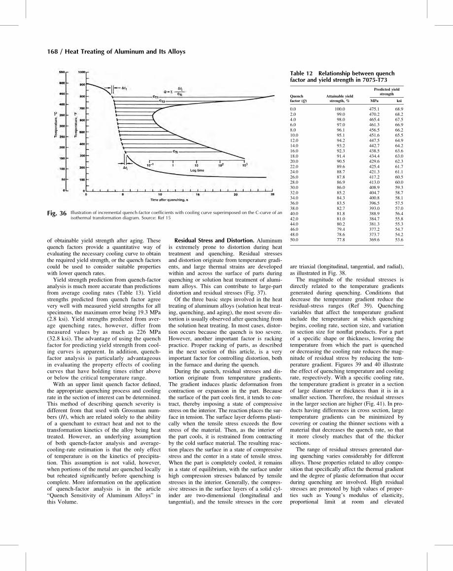
of obtainable yield strength after aging. Thesequench factors provide a quantitative way ofevaluating the necessary cooling curve to obtainthe required yield strength, or the quench factorscould be used to consider suitable propertieswith lower quench rates.Yield strength prediction from quench-factor
analysis is much more accurate than predictionsfrom average cooling rates (Table 13). Yieldstrengths predicted from quench factor agreevery well with measured yield strengths for allspecimens, the maximum error being 19.3 MPa(2.8 ksi). Yield strengths predicted from aver-age quenching rates, however, differ frommeasured values by as much as 226 MPa(32.8 ksi). The advantage of using the quenchfactor for predicting yield strength from cool-ing curves is apparent. In addition, quench-factor analysis is particularly advantageousin evaluating the property effects of coolingcurves that have holding times either aboveor below the critical temperature range.With an upper limit quench factor defined,
the appropriate quenching process and coolingrate in the section of interest can be determined.This method of describing quench severity isdifferent from that used with Grossman num-bers (H), which are related solely to the abilityof a quenchant to extract heat and not to thetransformation kinetics of the alloy being heattreated. However, an underlying assumptionof both quench-factor analysis and average-cooling-rate estimation is that the only effectof temperature is on the kinetics of precipita-tion. This assumption is not valid, however,when portions of the metal are quenched locallybut reheated significantly before quenching iscomplete. More information on the applicationof quench-factor analysis is in the article“Quench Sensitivity of Aluminum Alloys” inthis Volume.
Residual Stress and Distortion. Aluminumis extremely prone to distortion during heattreatment and quenching. Residual stressesand distortion originate from temperature gradi-ents, and large thermal strains are developedwithin and across the surface of parts duringquenching or solution heat treatment of alumi-num alloys. This can contribute to large-partdistortion and residual stresses (Fig. 37).Of the three basic steps involved in the heat
treating of aluminum alloys (solution heat treat-ing, quenching, and aging), the most severe dis-tortion is usually observed after quenching fromthe solution heat treating. In most cases, distor-tion occurs because the quench is too severe.However, another important factor is rackingpractice. Proper racking of parts, as describedin the next section of this article, is a veryimportant factor for controlling distortion, bothin the furnace and during the quench.During the quench, residual stresses and dis-
tortion originate from temperature gradients.The gradient induces plastic deformation fromcontraction or expansion in the part. Becausethe surface of the part cools first, it tends to con-tract, thereby imposing a state of compressivestress on the interior. The reaction places the sur-face in tension. The surface layer deforms plasti-cally when the tensile stress exceeds the flowstress of the material. Then, as the interior ofthe part cools, it is restrained from contractingby the cold surface material. The resulting reac-tion places the surface in a state of compressivestress and the center in a state of tensile stress.When the part is completely cooled, it remainsin a state of equilibrium, with the surface underhigh compression stresses balanced by tensilestresses in the interior. Generally, the compres-sive stresses in the surface layers of a solid cyl-inder are two-dimensional (longitudinal andtangential), and the tensile stresses in the core
are triaxial (longitudinal, tangential, and radial),as illustrated in Fig. 38.The magnitude of the residual stresses is
directly related to the temperature gradientsgenerated during quenching. Conditions thatdecrease the temperature gradient reduce theresidual-stress ranges (Ref 39). Quenchingvariables that affect the temperature gradientinclude the temperature at which quenchingbegins, cooling rate, section size, and variationin section size for nonflat products. For a partof a specific shape or thickness, lowering thetemperature from which the part is quenchedor decreasing the cooling rate reduces the mag-nitude of residual stress by reducing the tem-perature gradient. Figures 39 and 40 illustratethe effect of quenching temperature and coolingrate, respectively. With a specific cooling rate,the temperature gradient is greater in a sectionof large diameter or thickness than it is in asmaller section. Therefore, the residual stressesin the larger section are higher (Fig. 41). In pro-ducts having differences in cross section, largetemperature gradients can be minimized bycovering or coating the thinner sections with amaterial that decreases the quench rate, so thatit more closely matches that of the thickersections.The range of residual stresses generated dur-
ing quenching varies considerably for differentalloys. Those properties related to alloy compo-sition that specifically affect the thermal gradientand the degree of plastic deformation that occurduring quenching are involved. High residualstresses are promoted by high values of proper-ties such as Young’s modulus of elasticity,proportional limit at room and elevated
Fig. 36 Illustration of incremental quench-factor coefficients with cooling curve superimposed on the C-curve of anisothermal transformation diagram. Source: Ref 15
Table 12 Relationship between quenchfactor and yield strength in 7075-T73
Quenchfactor (Q)
Attainable yieldstrength, %
Predicted yieldstrength
MPa ksi
0.0 100.0 475.1 68.92.0 99.0 470.2 68.24.0 98.0 465.4 67.56.0 97.0 461.3 66.98.0 96.1 456.5 66.210.0 95.1 451.6 65.512.0 94.2 447.5 64.914.0 93.2 442.7 64.216.0 92.3 438.5 63.618.0 91.4 434.4 63.020.0 90.5 429.6 62.322.0 89.6 425.4 61.724.0 88.7 421.3 61.126.0 87.8 417.2 60.528.0 86.9 413.0 60.030.0 86.0 408.9 59.332.0 85.2 404.7 58.734.0 84.3 400.8 58.136.0 83.5 396.5 57.538.0 82.7 393.0 57.040.0 81.8 388.9 56.442.0 81.0 384.7 55.844.0 80.2 381.3 55.346.0 79.4 377.2 54.748.0 78.6 373.7 54.250.0 77.8 369.6 53.6
168 / Heat Treating of Aluminum and Its Alloys
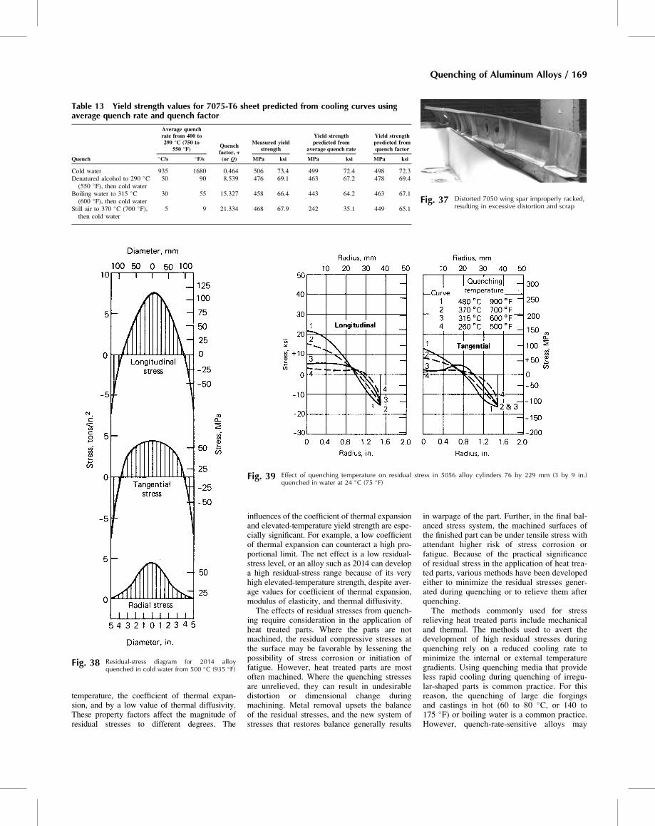
temperature, the coefficient of thermal expan-sion, and by a low value of thermal diffusivity.These property factors affect the magnitude ofresidual stresses to different degrees. The
influences of the coefficient of thermal expansionand elevated-temperature yield strength are espe-cially significant. For example, a low coefficientof thermal expansion can counteract a high pro-portional limit. The net effect is a low residual-stress level, or an alloy such as 2014 can developa high residual-stress range because of its veryhigh elevated-temperature strength, despite aver-age values for coefficient of thermal expansion,modulus of elasticity, and thermal diffusivity.The effects of residual stresses from quench-
ing require consideration in the application ofheat treated parts. Where the parts are notmachined, the residual compressive stresses atthe surface may be favorable by lessening thepossibility of stress corrosion or initiation offatigue. However, heat treated parts are mostoften machined. Where the quenching stressesare unrelieved, they can result in undesirabledistortion or dimensional change duringmachining. Metal removal upsets the balanceof the residual stresses, and the new system ofstresses that restores balance generally results
in warpage of the part. Further, in the final bal-anced stress system, the machined surfaces ofthe finished part can be under tensile stress withattendant higher risk of stress corrosion orfatigue. Because of the practical significanceof residual stress in the application of heat trea-ted parts, various methods have been developedeither to minimize the residual stresses gener-ated during quenching or to relieve them afterquenching.The methods commonly used for stress
relieving heat treated parts include mechanicaland thermal. The methods used to avert thedevelopment of high residual stresses duringquenching rely on a reduced cooling rate tominimize the internal or external temperaturegradients. Using quenching media that provideless rapid cooling during quenching of irregu-lar-shaped parts is common practice. For thisreason, the quenching of large die forgingsand castings in hot (60 to 80 �C, or 140 to175 �F) or boiling water is a common practice.However, quench-rate-sensitive alloys may
Fig. 37 Distorted 7050 wing spar improperly racked,resulting in excessive distortion and scrap
Fig. 38 Residual-stress diagram for 2014 alloyquenched in cold water from 500 �C (935 �F)
Table 13 Yield strength values for 7075-T6 sheet predicted from cooling curves usingaverage quench rate and quench factor
Quench
Average quenchrate from 400 to290 �C (750 to
550 �F) Quenchfactor, t(or Q)
Measured yieldstrength
Yield strengthpredicted from
average quench rate
Yield strengthpredicted fromquench factor
�C/s �F/s MPa ksi MPa ksi MPa ksi
Cold water 935 1680 0.464 506 73.4 499 72.4 498 72.3Denatured alcohol to 290 �C(550 �F), then cold water
50 90 8.539 476 69.1 463 67.2 478 69.4
Boiling water to 315 �C(600 �F), then cold water
30 55 15.327 458 66.4 443 64.2 463 67.1
Still air to 370 �C (700 �F),then cold water
5 9 21.334 468 67.9 242 35.1 449 65.1
Fig. 39 Effect of quenching temperature on residual stress in 5056 alloy cylinders 76 by 229 mm (3 by 9 in.)quenched in water at 24 �C (75 �F)
Quenching of Aluminum Alloys / 169
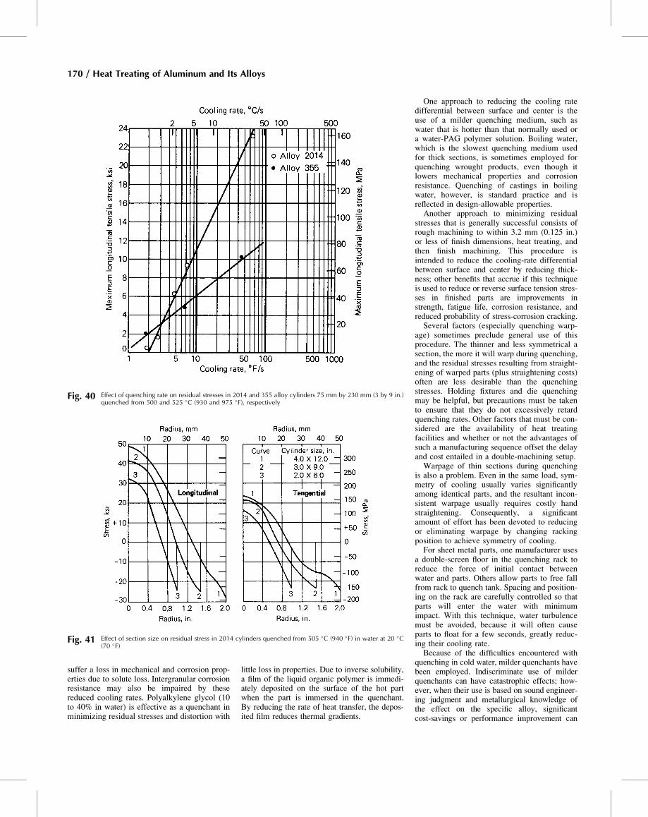
suffer a loss in mechanical and corrosion prop-erties due to solute loss. Intergranular corrosionresistance may also be impaired by thesereduced cooling rates. Polyalkylene glycol (10to 40% in water) is effective as a quenchant inminimizing residual stresses and distortion with
little loss in properties. Due to inverse solubility,a film of the liquid organic polymer is immedi-ately deposited on the surface of the hot partwhen the part is immersed in the quenchant.By reducing the rate of heat transfer, the depos-ited film reduces thermal gradients.
One approach to reducing the cooling ratedifferential between surface and center is theuse of a milder quenching medium, such aswater that is hotter than that normally used ora water-PAG polymer solution. Boiling water,which is the slowest quenching medium usedfor thick sections, is sometimes employed forquenching wrought products, even though itlowers mechanical properties and corrosionresistance. Quenching of castings in boilingwater, however, is standard practice and isreflected in design-allowable properties.Another approach to minimizing residual
stresses that is generally successful consists ofrough machining to within 3.2 mm (0.125 in.)or less of finish dimensions, heat treating, andthen finish machining. This procedure isintended to reduce the cooling-rate differentialbetween surface and center by reducing thick-ness; other benefits that accrue if this techniqueis used to reduce or reverse surface tension stres-ses in finished parts are improvements instrength, fatigue life, corrosion resistance, andreduced probability of stress-corrosion cracking.Several factors (especially quenching warp-
age) sometimes preclude general use of thisprocedure. The thinner and less symmetrical asection, the more it will warp during quenching,and the residual stresses resulting from straight-ening of warped parts (plus straightening costs)often are less desirable than the quenchingstresses. Holding fixtures and die quenchingmay be helpful, but precautions must be takento ensure that they do not excessively retardquenching rates. Other factors that must be con-sidered are the availability of heat treatingfacilities and whether or not the advantages ofsuch a manufacturing sequence offset the delayand cost entailed in a double-machining setup.Warpage of thin sections during quenching
is also a problem. Even in the same load, sym-metry of cooling usually varies significantlyamong identical parts, and the resultant incon-sistent warpage usually requires costly handstraightening. Consequently, a significantamount of effort has been devoted to reducingor eliminating warpage by changing rackingposition to achieve symmetry of cooling.For sheet metal parts, one manufacturer uses
a double-screen floor in the quenching rack toreduce the force of initial contact betweenwater and parts. Others allow parts to free fallfrom rack to quench tank. Spacing and position-ing on the rack are carefully controlled so thatparts will enter the water with minimumimpact. With this technique, water turbulencemust be avoided, because it will often causeparts to float for a few seconds, greatly reduc-ing their cooling rate.Because of the difficulties encountered with
quenching in cold water, milder quenchants havebeen employed. Indiscriminate use of milderquenchants can have catastrophic effects; how-ever, when their use is based on sound engineer-ing judgment and metallurgical knowledge ofthe effect on the specific alloy, significantcost-savings or performance improvement can
Fig. 40 Effect of quenching rate on residual stresses in 2014 and 355 alloy cylinders 75 mm by 230 mm (3 by 9 in.)quenched from 500 and 525 �C (930 and 975 �F), respectively
Fig. 41 Effect of section size on residual stress in 2014 cylinders quenched from 505 �C (940 �F) in water at 20 �C(70 �F)
170 / Heat Treating of Aluminum and Its Alloys
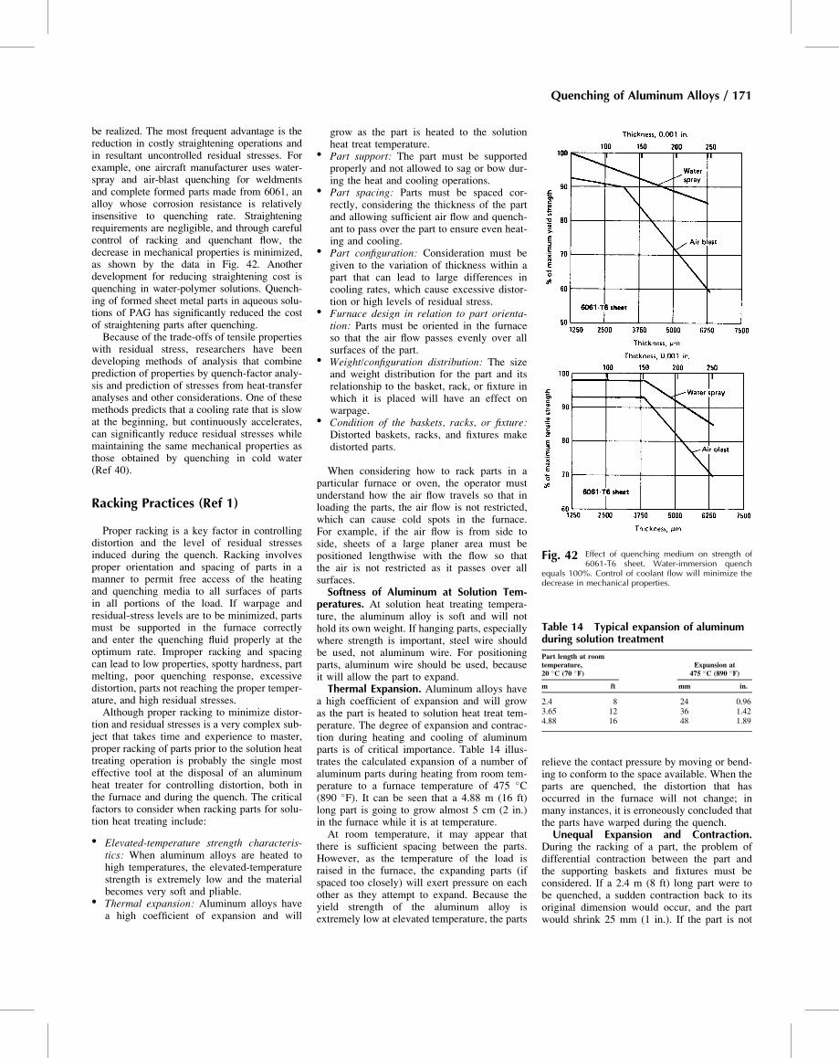
be realized. The most frequent advantage is thereduction in costly straightening operations andin resultant uncontrolled residual stresses. Forexample, one aircraft manufacturer uses water-spray and air-blast quenching for weldmentsand complete formed parts made from 6061, analloy whose corrosion resistance is relativelyinsensitive to quenching rate. Straighteningrequirements are negligible, and through carefulcontrol of racking and quenchant flow, thedecrease in mechanical properties is minimized,as shown by the data in Fig. 42. Anotherdevelopment for reducing straightening cost isquenching in water-polymer solutions. Quench-ing of formed sheet metal parts in aqueous solu-tions of PAG has significantly reduced the costof straightening parts after quenching.Because of the trade-offs of tensile properties
with residual stress, researchers have beendeveloping methods of analysis that combineprediction of properties by quench-factor analy-sis and prediction of stresses from heat-transferanalyses and other considerations. One of thesemethods predicts that a cooling rate that is slowat the beginning, but continuously accelerates,can significantly reduce residual stresses whilemaintaining the same mechanical properties asthose obtained by quenching in cold water(Ref 40).
Racking Practices (Ref 1)
Proper racking is a key factor in controllingdistortion and the level of residual stressesinduced during the quench. Racking involvesproper orientation and spacing of parts in amanner to permit free access of the heatingand quenching media to all surfaces of partsin all portions of the load. If warpage andresidual-stress levels are to be minimized, partsmust be supported in the furnace correctlyand enter the quenching fluid properly at theoptimum rate. Improper racking and spacingcan lead to low properties, spotty hardness, partmelting, poor quenching response, excessivedistortion, parts not reaching the proper temper-ature, and high residual stresses.Although proper racking to minimize distor-
tion and residual stresses is a very complex sub-ject that takes time and experience to master,proper racking of parts prior to the solution heattreating operation is probably the single mosteffective tool at the disposal of an aluminumheat treater for controlling distortion, both inthe furnace and during the quench. The criticalfactors to consider when racking parts for solu-tion heat treating include:
� Elevated-temperature strength characteris-tics: When aluminum alloys are heated tohigh temperatures, the elevated-temperaturestrength is extremely low and the materialbecomes very soft and pliable.
� Thermal expansion: Aluminum alloys havea high coefficient of expansion and will
grow as the part is heated to the solutionheat treat temperature.
� Part support: The part must be supportedproperly and not allowed to sag or bow dur-ing the heat and cooling operations.
� Part spacing: Parts must be spaced cor-rectly, considering the thickness of the partand allowing sufficient air flow and quench-ant to pass over the part to ensure even heat-ing and cooling.
� Part configuration: Consideration must begiven to the variation of thickness within apart that can lead to large differences incooling rates, which cause excessive distor-tion or high levels of residual stress.
� Furnace design in relation to part orienta-tion: Parts must be oriented in the furnaceso that the air flow passes evenly over allsurfaces of the part.
� Weight/configuration distribution: The sizeand weight distribution for the part and itsrelationship to the basket, rack, or fixture inwhich it is placed will have an effect onwarpage.
� Condition of the baskets, racks, or fixture:Distorted baskets, racks, and fixtures makedistorted parts.
When considering how to rack parts in aparticular furnace or oven, the operator mustunderstand how the air flow travels so that inloading the parts, the air flow is not restricted,which can cause cold spots in the furnace.For example, if the air flow is from side toside, sheets of a large planer area must bepositioned lengthwise with the flow so thatthe air is not restricted as it passes over allsurfaces.Softness of Aluminum at Solution Tem-
peratures. At solution heat treating tempera-ture, the aluminum alloy is soft and will nothold its own weight. If hanging parts, especiallywhere strength is important, steel wire shouldbe used, not aluminum wire. For positioningparts, aluminum wire should be used, becauseit will allow the part to expand.Thermal Expansion. Aluminum alloys have
a high coefficient of expansion and will growas the part is heated to solution heat treat tem-perature. The degree of expansion and contrac-tion during heating and cooling of aluminumparts is of critical importance. Table 14 illus-trates the calculated expansion of a number ofaluminum parts during heating from room tem-perature to a furnace temperature of 475 �C(890 �F). It can be seen that a 4.88 m (16 ft)long part is going to grow almost 5 cm (2 in.)in the furnace while it is at temperature.At room temperature, it may appear that
there is sufficient spacing between the parts.However, as the temperature of the load israised in the furnace, the expanding parts (ifspaced too closely) will exert pressure on eachother as they attempt to expand. Because theyield strength of the aluminum alloy isextremely low at elevated temperature, the parts
relieve the contact pressure by moving or bend-ing to conform to the space available. When theparts are quenched, the distortion that hasoccurred in the furnace will not change; inmany instances, it is erroneously concluded thatthe parts have warped during the quench.Unequal Expansion and Contraction.
During the racking of a part, the problem ofdifferential contraction between the part andthe supporting baskets and fixtures must beconsidered. If a 2.4 m (8 ft) long part were tobe quenched, a sudden contraction back to itsoriginal dimension would occur, and the partwould shrink 25 mm (1 in.). If the part is not
Fig. 42 Effect of quenching medium on strength of6061-T6 sheet. Water-immersion quench
equals 100%. Control of coolant flow will minimize thedecrease in mechanical properties.
Table 14 Typical expansion of aluminumduring solution treatment
Part length at roomtemperature,20 �C (70 �F)
Expansion at475 �C (890 �F)
m ft mm in.
2.4 8 24 0.963.65 12 36 1.424.88 16 48 1.89
Quenching of Aluminum Alloys / 171
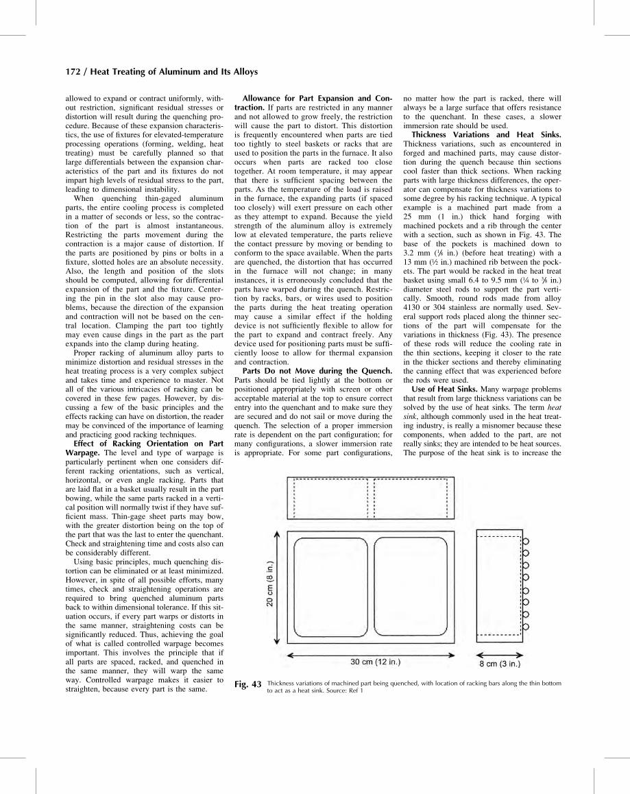
allowed to expand or contract uniformly, with-out restriction, significant residual stresses ordistortion will result during the quenching pro-cedure. Because of these expansion characteris-tics, the use of fixtures for elevated-temperatureprocessing operations (forming, welding, heattreating) must be carefully planned so thatlarge differentials between the expansion char-acteristics of the part and its fixtures do notimpart high levels of residual stress to the part,leading to dimensional instability.When quenching thin-gaged aluminum
parts, the entire cooling process is completedin a matter of seconds or less, so the contrac-tion of the part is almost instantaneous.Restricting the parts movement during thecontraction is a major cause of distortion. Ifthe parts are positioned by pins or bolts in afixture, slotted holes are an absolute necessity.Also, the length and position of the slotsshould be computed, allowing for differentialexpansion of the part and the fixture. Center-ing the pin in the slot also may cause pro-blems, because the direction of the expansionand contraction will not be based on the cen-tral location. Clamping the part too tightlymay even cause dings in the part as the partexpands into the clamp during heating.Proper racking of aluminum alloy parts to
minimize distortion and residual stresses in theheat treating process is a very complex subjectand takes time and experience to master. Notall of the various intricacies of racking can becovered in these few pages. However, by dis-cussing a few of the basic principles and theeffects racking can have on distortion, the readermay be convinced of the importance of learningand practicing good racking techniques.Effect of Racking Orientation on Part
Warpage. The level and type of warpage isparticularly pertinent when one considers dif-ferent racking orientations, such as vertical,horizontal, or even angle racking. Parts thatare laid flat in a basket usually result in the partbowing, while the same parts racked in a verti-cal position will normally twist if they have suf-ficient mass. Thin-gage sheet parts may bow,with the greater distortion being on the top ofthe part that was the last to enter the quenchant.Check and straightening time and costs also canbe considerably different.Using basic principles, much quenching dis-
tortion can be eliminated or at least minimized.However, in spite of all possible efforts, manytimes, check and straightening operations arerequired to bring quenched aluminum partsback to within dimensional tolerance. If this sit-uation occurs, if every part warps or distorts inthe same manner, straightening costs can besignificantly reduced. Thus, achieving the goalof what is called controlled warpage becomesimportant. This involves the principle that ifall parts are spaced, racked, and quenched inthe same manner, they will warp the sameway. Controlled warpage makes it easier tostraighten, because every part is the same.
Allowance for Part Expansion and Con-traction. If parts are restricted in any mannerand not allowed to grow freely, the restrictionwill cause the part to distort. This distortionis frequently encountered when parts are tiedtoo tightly to steel baskets or racks that areused to position the parts in the furnace. It alsooccurs when parts are racked too closetogether. At room temperature, it may appearthat there is sufficient spacing between theparts. As the temperature of the load is raisedin the furnace, the expanding parts (if spacedtoo closely) will exert pressure on each otheras they attempt to expand. Because the yieldstrength of the aluminum alloy is extremelylow at elevated temperature, the parts relievethe contact pressure by moving or bending toconform to the space available. When the partsare quenched, the distortion that has occurredin the furnace will not change; in manyinstances, it is erroneously concluded that theparts have warped during the quench. Restric-tion by racks, bars, or wires used to positionthe parts during the heat treating operationmay cause a similar effect if the holdingdevice is not sufficiently flexible to allow forthe part to expand and contract freely. Anydevice used for positioning parts must be suffi-ciently loose to allow for thermal expansionand contraction.Parts Do not Move during the Quench.
Parts should be tied lightly at the bottom orpositioned appropriately with screen or otheracceptable material at the top to ensure correctentry into the quenchant and to make sure theyare secured and do not sail or move during thequench. The selection of a proper immersionrate is dependent on the part configuration; formany configurations, a slower immersion rateis appropriate. For some part configurations,
no matter how the part is racked, there willalways be a large surface that offers resistanceto the quenchant. In these cases, a slowerimmersion rate should be used.Thickness Variations and Heat Sinks.
Thickness variations, such as encountered inforged and machined parts, may cause distor-tion during the quench because thin sectionscool faster than thick sections. When rackingparts with large thickness differences, the oper-ator can compensate for thickness variations tosome degree by his racking technique. A typicalexample is a machined part made from a25 mm (1 in.) thick hand forging withmachined pockets and a rib through the centerwith a section, such as shown in Fig. 43. Thebase of the pockets is machined down to3.2 mm (1/8 in.) (before heat treating) with a13 mm (½ in.) machined rib between the pock-ets. The part would be racked in the heat treatbasket using small 6.4 to 9.5 mm (¼ to 3/8 in.)diameter steel rods to support the part verti-cally. Smooth, round rods made from alloy4130 or 304 stainless are normally used. Sev-eral support rods placed along the thinner sec-tions of the part will compensate for thevariations in thickness (Fig. 43). The presenceof these rods will reduce the cooling rate inthe thin sections, keeping it closer to the ratein the thicker sections and thereby eliminatingthe canning effect that was experienced beforethe rods were used.Use of Heat Sinks. Many warpage problems
that result from large thickness variations can besolved by the use of heat sinks. The term heatsink, although commonly used in the heat treat-ing industry, is really a misnomer because thesecomponents, when added to the part, are notreally sinks; they are intended to be heat sources.The purpose of the heat sink is to increase the
Fig. 43 Thickness variations of machined part being quenched, with location of racking bars along the thin bottomto act as a heat sink. Source: Ref 1
172 / Heat Treating of Aluminum and Its Alloys
mass of the part in a specific area so that moreequalized cooling is achieved throughout theentire part. Increasing the thickness or mass ina thin area allows that area to cool at the samerate as thicker areas, thereby reducing the warp-age during the cooling process.The use of heat sinks must be done carefully.
It must be performed in a manner so that thearea of the part is not cooled so much that itaffects the final heat treat properties. Inspectionof the affected area must be rigidly controlled.In some instances, application of quench-sensi-tivity data can be helpful in determining thetype and size of the method used. Also, carefuladherence to specification requirements must bepracticed. Some prime contractors do not allowthe use of heat sinks without prior approval.Heat sinks take on different forms. It is com-
mon practice to use aluminum screen, some-times bunched in a ball or wrapped around analuminum block, to act as a heat sink. Thistechnique has proven to be effective incontrolling differential quenching rates in manycases.To compensate for severe canning distortion
in the machined pockets of a large wing spar,another example involved the use of cast alumi-num waffle plates, which were positioned in thebottom of each pocket to equalize the coolingrates with the surrounding ribs. The waffle plateswere fastened to the part using bolt through holesin each pocket, and they completely eliminatedthe canning of the pocket areas.Spacing of Parts. As previously noted, the
fundamental requirement of proper racking isthat “all parts be racked or supported in a man-ner to permit free access of the heating andquenching media to all surfaces of parts in allportions of the load.” This requirement estab-lishes that parts must be spaced properly toensure the free access of the heating and quench-ing media. Most specifications have this require-ment in some way or another. Unfortunately,there is a wide difference of opinion among mostexperts regarding the exact spacing that is neededto achieve this goal. Specification requirementsvary significantly regarding the exact spacing thatis needed. Some companies leave the spacingrequirement up to the heat treater as long as theprimary requirement is met.The first requirement of racking for the
quench is to allow sufficient space around eachpart so the quench medium has free access toall surfaces. This spacing is essential so thatthe fluid can effectively extract heat from allsurfaces uniformly throughout the entirequench. Allowing the quenchant to becometoo hot in any location near the part becauseof improper spacing or inadequate agitationcan lead to distortion and lower mechanicalproperties.Problems often occur while quenching some
of the bulkier forgings and castings. At firstappearance, because of their size and thickness,distortion would not appear to be a problem. Toobtain the most production from the available
equipment, the heat treater may stack or simplydump parts into the basket. When the parts arequenched, the lack of proper spacing does notallow free access of the quenching fluid. Whenonly small amounts of fluid (usually water)reach between parts, local steam or vapor pock-ets develop. The presence of these vapor pock-ets slows down the cooling rate at theselocations. Slower cooling rates allow the alloy-ing elements to come out of solid solution, andthe loss of these alloying constituents can resultin a significant loss of hardness and strengthproperties after aging. The reduced propertiesare usually observed in the parts during hard-ness testing and normally appear as soft spots.In some cases, entire parts will be below theminimum hardness and strength requirementsfor that alloy and temper.Distortion or the inducement of unwanted
residual stresses can easily occur in heavierparts when inadequate or uneven spacing isused. Spacing should increase with the partthickness, because it will require a larger vol-ume of quenchant between parts to extract thegreater amount of heat contained in the thickerpart. When quenching in water, the spacingbetween parts should be increased as the watertemperature is increased. The quenching powerof water decreases as it is heated. Water tem-peratures above 70 �C (160 �F) exhibit veryslow cooling rates and should not be used formost of the thicker parts unless allowances aremade for reduced properties.
Quench Tank Systems
Immersion in tanks, frequently of unlinedwaterproof concrete, particularly if they arebelow floor level, is the most usual method.Small tanks and those above floor level usuallyare metal. Aluminum or stainless steel is pre-ferred for metal tanks. If carbon steel is used,suitable surface coatings must be applied tosuppress corrosion, which can cause stainingof the product. Water used for quenching alsomay contain a small percentage (usually lessthan 1 to 2%) of a rust inhibitor to minimizerusting of the quench tank and racks.Quench tanks must be large enough to permit
the furnace charge to be immersed completely,preferably below the excessively heated toplayer of water. For quenches specified at roomtemperature, water volume should be sufficientto maintain the bath below 40 �C (100 �F) dur-ing the quenching cycle. If this is not practical,bath temperature must be kept below this max-imum through vigorous agitation by suchmeans as high-velocity introduction of make-up water or recirculation with pumps or propel-ler-type mixers. When slower quench rates arerequired, the quenching medium may be keptabove normal ambient temperature by addingsuitable heating coils or steam injection facilitiesto the tank. Uniform quench bath temperature isessential to optimum product characteristics.
The practical aspects and design considera-tions of a quench system involve a number ofvariables that include alloy type, product type,load configuration, quenchant fluid, agitationrate, total load weight, and the density of theload on the racks. The focus of this section ison design considerations for immersion tanksystems in terms of:
� Batch or continuous process� Materials selection� Heat load� Quench tank and rinse tank agitation� Part tacking and baskets� Cooling/heating� Fluid maintenance� Concentration control and separation methods
Some practical aspects of quench systemdesign depend on product type. For example,quench systems are typically divided accordingto product gage: one for sheet metal parts andparts up to 6 mm (¼ in.) thickness, or a systemfor heavier-gage parts that have cross sectionsmore than 6 mm (¼ in.) thick. The main differ-ence between sheet metal quenching and aheavy-gage load is the fact that sheet metal willnormally be cooled by the time the parts reachthe bottom of the quench bath. The hoist or ele-vator provides the main means of agitation forthe cooling cycle, while the agitator system onlyneeds to provide proper mixing and uniformityof the tank before and during the quench.Batch or Continuous Process. Quench
tanks will support either a batch process or acontinuous process. Batch quenching is usedfor furnaces that use an indexing system topresent a load for quenching in a tank sizedwith enough volume of quench that the temper-ature rise in the tank is within acceptable limitsfor each quench cycle. Other types of furnacesare horizontal or vertical quench furnaces(drop-bottom furnaces).Continuous quench tanks are sized with
enough volume of liquid to allow for properagitation and heat removal from the work as itis quenched. This, in connection with a prop-erly sized cooling system, ensures the processcan continue without exceeding the upper limitof quench temperature. Several different meth-ods are used to provide proper flow and coolingfor the parts. There are chute quench systems,spray quenching, and simple tanks with a belt.Continuous quench tanks are mostly employedin connection with belt furnaces. Other typesof furnaces are walking beam furnaces or screwfurnaces. The continuous quench tanks accom-modate both bulk products and single-pieceproduct quenching.Tank Materials Selection. Aluminum can be
affected by free iron (rust) in the quench bathduring the quenching. Surface corrosion is par-ticularly troublesome with sheet metal parts.The corrosion will show up as dark splotchesthat, with closer examination, reveal a black spotin the center (iron particle). Free iron is not the
Quenching of Aluminum Alloys / 173
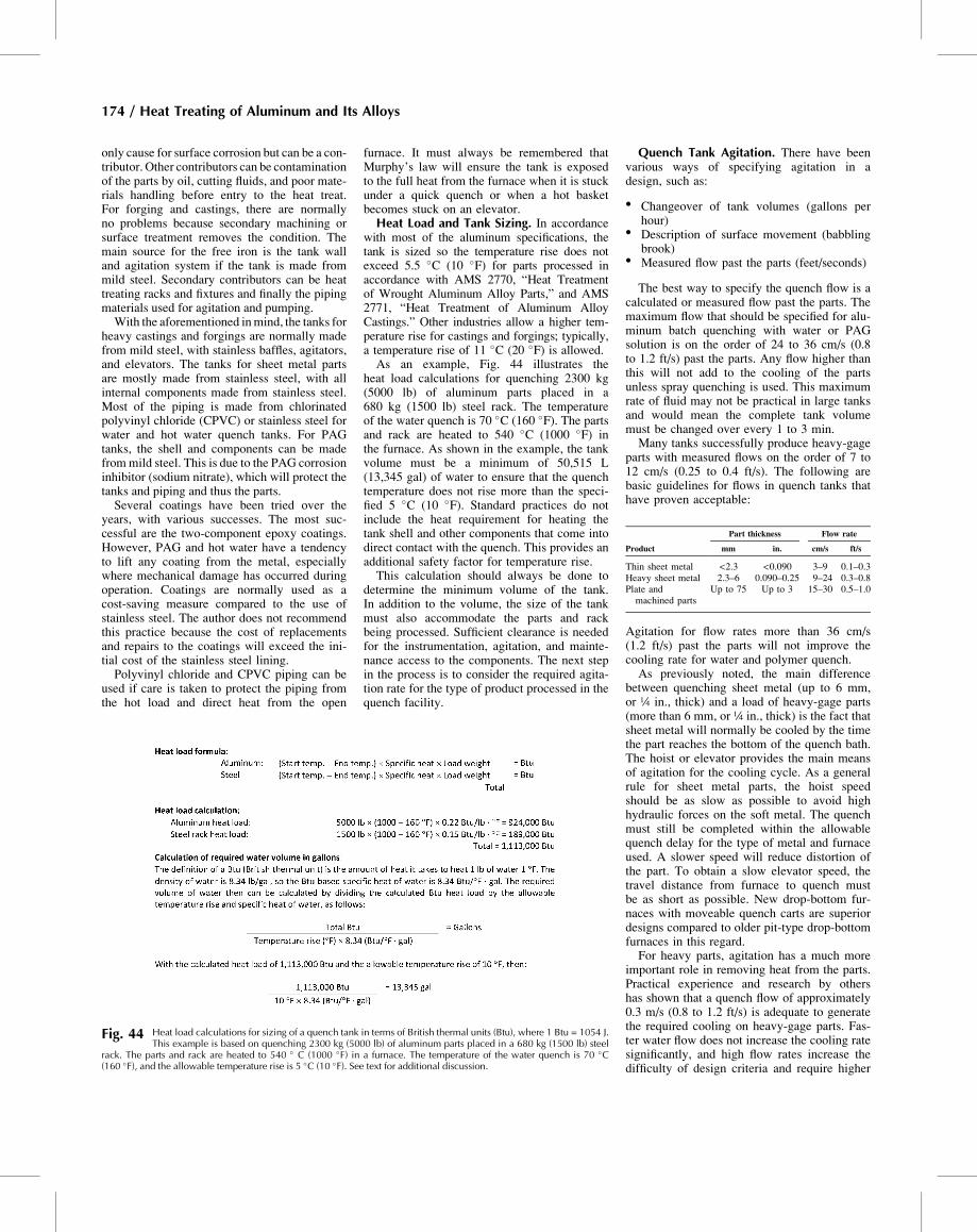
only cause for surface corrosion but can be a con-tributor. Other contributors can be contaminationof the parts by oil, cutting fluids, and poor mate-rials handling before entry to the heat treat.For forging and castings, there are normallyno problems because secondary machining orsurface treatment removes the condition. Themain source for the free iron is the tank walland agitation system if the tank is made frommild steel. Secondary contributors can be heattreating racks and fixtures and finally the pipingmaterials used for agitation and pumping.With the aforementioned inmind, the tanks for
heavy castings and forgings are normally madefrom mild steel, with stainless baffles, agitators,and elevators. The tanks for sheet metal partsare mostly made from stainless steel, with allinternal components made from stainless steel.Most of the piping is made from chlorinatedpolyvinyl chloride (CPVC) or stainless steel forwater and hot water quench tanks. For PAGtanks, the shell and components can be madefrommild steel. This is due to the PAG corrosioninhibitor (sodium nitrate), which will protect thetanks and piping and thus the parts.Several coatings have been tried over the
years, with various successes. The most suc-cessful are the two-component epoxy coatings.However, PAG and hot water have a tendencyto lift any coating from the metal, especiallywhere mechanical damage has occurred duringoperation. Coatings are normally used as acost-saving measure compared to the use ofstainless steel. The author does not recommendthis practice because the cost of replacementsand repairs to the coatings will exceed the ini-tial cost of the stainless steel lining.Polyvinyl chloride and CPVC piping can be
used if care is taken to protect the piping fromthe hot load and direct heat from the open
furnace. It must always be remembered thatMurphy’s law will ensure the tank is exposedto the full heat from the furnace when it is stuckunder a quick quench or when a hot basketbecomes stuck on an elevator.Heat Load and Tank Sizing. In accordance
with most of the aluminum specifications, thetank is sized so the temperature rise does notexceed 5.5 �C (10 �F) for parts processed inaccordance with AMS 2770, “Heat Treatmentof Wrought Aluminum Alloy Parts,” and AMS2771, “Heat Treatment of Aluminum AlloyCastings.” Other industries allow a higher tem-perature rise for castings and forgings; typically,a temperature rise of 11 �C (20 �F) is allowed.As an example, Fig. 44 illustrates the
heat load calculations for quenching 2300 kg(5000 lb) of aluminum parts placed in a680 kg (1500 lb) steel rack. The temperatureof the water quench is 70 �C (160 �F). The partsand rack are heated to 540 �C (1000 �F) inthe furnace. As shown in the example, the tankvolume must be a minimum of 50,515 L(13,345 gal) of water to ensure that the quenchtemperature does not rise more than the speci-fied 5 �C (10 �F). Standard practices do notinclude the heat requirement for heating thetank shell and other components that come intodirect contact with the quench. This provides anadditional safety factor for temperature rise.This calculation should always be done to
determine the minimum volume of the tank.In addition to the volume, the size of the tankmust also accommodate the parts and rackbeing processed. Sufficient clearance is neededfor the instrumentation, agitation, and mainte-nance access to the components. The next stepin the process is to consider the required agita-tion rate for the type of product processed in thequench facility.
Quench Tank Agitation. There have beenvarious ways of specifying agitation in adesign, such as:
� Changeover of tank volumes (gallons perhour)
� Description of surface movement (babblingbrook)
� Measured flow past the parts (feet/seconds)
The best way to specify the quench flow is acalculated or measured flow past the parts. Themaximum flow that should be specified for alu-minum batch quenching with water or PAGsolution is on the order of 24 to 36 cm/s (0.8to 1.2 ft/s) past the parts. Any flow higher thanthis will not add to the cooling of the partsunless spray quenching is used. This maximumrate of fluid may not be practical in large tanksand would mean the complete tank volumemust be changed over every 1 to 3 min.Many tanks successfully produce heavy-gage
parts with measured flows on the order of 7 to12 cm/s (0.25 to 0.4 ft/s). The following arebasic guidelines for flows in quench tanks thathave proven acceptable:
Product
Part thickness Flow rate
mm in. cm/s ft/s
Thin sheet metal <2.3 <0.090 3–9 0.1–0.3Heavy sheet metal 2.3–6 0.090–0.25 9–24 0.3–0.8Plate andmachined parts
Up to 75 Up to 3 15–30 0.5–1.0
Agitation for flow rates more than 36 cm/s(1.2 ft/s) past the parts will not improve thecooling rate for water and polymer quench.As previously noted, the main difference
between quenching sheet metal (up to 6 mm,or ¼ in., thick) and a load of heavy-gage parts(more than 6 mm, or ¼ in., thick) is the fact thatsheet metal will normally be cooled by the timethe part reaches the bottom of the quench bath.The hoist or elevator provides the main meansof agitation for the cooling cycle. As a generalrule for sheet metal parts, the hoist speedshould be as slow as possible to avoid highhydraulic forces on the soft metal. The quenchmust still be completed within the allowablequench delay for the type of metal and furnaceused. A slower speed will reduce distortion ofthe part. To obtain a slow elevator speed, thetravel distance from furnace to quench mustbe as short as possible. New drop-bottom fur-naces with moveable quench carts are superiordesigns compared to older pit-type drop-bottomfurnaces in this regard.For heavy parts, agitation has a much more
important role in removing heat from the parts.Practical experience and research by othershas shown that a quench flow of approximately0.3 m/s (0.8 to 1.2 ft/s) is adequate to generatethe required cooling on heavy-gage parts. Fas-ter water flow does not increase the cooling ratesignificantly, and high flow rates increase thedifficulty of design criteria and require higher
Fig. 44 Heat load calculations for sizing of a quench tank in terms of British thermal units (Btu), where 1 Btu = 1054 J.This example is based on quenching 2300 kg (5000 lb) of aluminum parts placed in a 680 kg (1500 lb) steel
rack. The parts and rack are heated to 540 � C (1000 �F) in a furnace. The temperature of the water quench is 70 �C(160 �F), and the allowable temperature rise is 5 �C (10 �F). See text for additional discussion.
174 / Heat Treating of Aluminum and Its Alloys
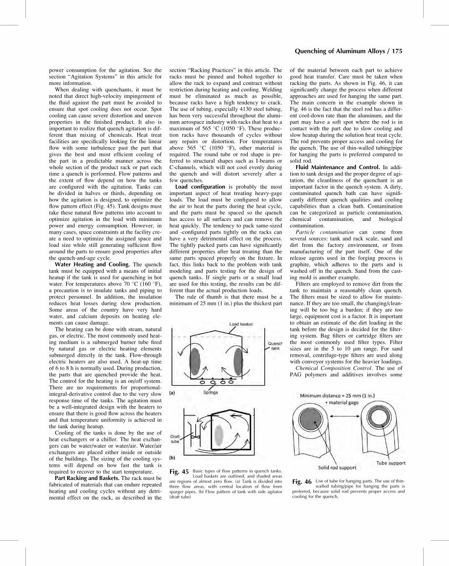
power consumption for the agitation. See thesection “Agitation Systems” in this article formore information.When dealing with quenchants, it must be
noted that direct high-velocity impingement ofthe fluid against the part must be avoided toensure that spot cooling does not occur. Spotcooling can cause severe distortion and unevenproperties in the finished product. It also isimportant to realize that quench agitation is dif-ferent than mixing of chemicals. Heat treatfacilities are specifically looking for the linearflow with some turbulence past the part thatgives the best and most efficient cooling ofthe part in a predictable manner across thewhole section of the product rack or part eachtime a quench is performed. Flow patterns andthe extent of flow depend on how the tanksare configured with the agitation. Tanks canbe divided in halves or thirds, depending onhow the agitation is designed, to optimize theflow pattern effect (Fig. 45). Tank designs musttake these natural flow patterns into account tooptimize agitation in the load with minimumpower and energy consumption. However, inmany cases, space constraints at the facility cre-ate a need to optimize the assigned space andload size while still generating sufficient flowaround the parts to ensure good properties afterthe quench-and-age cycle.Water Heating and Cooling. The quench
tank must be equipped with a means of initialheatup if the tank is used for quenching in hotwater. For temperatures above 70 �C (160 �F),a precaution is to insulate tanks and piping toprotect personnel. In addition, the insulationreduces heat losses during slow production.Some areas of the country have very hardwater, and calcium deposits on heating ele-ments can cause damage.The heating can be done with steam, natural
gas, or electric. The most commonly used heat-ing medium is a submerged burner tube firedby natural gas or electric heating elementssubmerged directly in the tank. Flow-throughelectric heaters are also used. A heat-up timeof 6 to 8 h is normally used. During production,the parts that are quenched provide the heat.The control for the heating is an on/off system.There are no requirements for proportional-integral-derivative control due to the very slowresponse time of the tanks. The agitation mustbe a well-integrated design with the heaters toensure that there is good flow across the heatersand that temperature uniformity is achieved inthe tank during heatup.Cooling of the tanks is done by the use of
heat exchangers or a chiller. The heat exchan-gers can be water/water or water/air. Water/airexchangers are placed either inside or outsideof the buildings. The sizing of the cooling sys-tems will depend on how fast the tank isrequired to recover to the start temperature.Part Racking and Baskets. The rack must be
fabricated of materials that can endure repeatedheating and cooling cycles without any detri-mental effect on the rack, as described in the
section “Racking Practices” in this article. Theracks must be pinned and bolted together toallow the rack to expand and contract withoutrestriction during heating and cooling. Weldingmust be eliminated as much as possible,because racks have a high tendency to crack.The use of tubing, especially 4130 steel tubing,has been very successful throughout the alumi-num aerospace industry with racks that heat to amaximum of 565 �C (1050 �F). These produc-tion racks have thousands of cycles withoutany repairs or distortion. For temperaturesabove 565 �C (1050 �F), other material isrequired. The round tube or rod shape is pre-ferred to structural shapes such as I-beams orC-channels, which will not cool evenly duringthe quench and will distort severely after afew quenches.Load configuration is probably the most
important aspect of heat treating heavy-gageloads. The load must be configured to allowthe air to heat the parts during the heat cycle,and the parts must be spaced so the quenchhas access to all surfaces and can remove theheat quickly. The tendency to pack same-sizedand -configured parts tightly on the racks canhave a very detrimental effect on the process.The tightly packed parts can have significantlydifferent properties after heat treating than thesame parts spaced properly on the fixture. Infact, this links back to the problem with tankmodeling and parts testing for the design ofquench tanks. If single parts or a small loadare used for this testing, the results can be dif-ferent than the actual production loads.The rule of thumb is that there must be a
minimum of 25 mm (1 in.) plus the thickest part
of the material between each part to achievegood heat transfer. Care must be taken whenracking the parts. As shown in Fig. 46, it cansignificantly change the process when differentapproaches are used for hanging the same part.The main concern in the example shown inFig. 46 is the fact that the steel rod has a differ-ent cool-down rate than the aluminum, and thepart may have a soft spot where the rod is incontact with the part due to slow cooling andslow heatup during the solution heat treat cycle.The rod prevents proper access and cooling forthe quench. The use of thin-walled tubing/pipefor hanging the parts is preferred compared tosolid rod.Fluid Maintenance and Control. In addi-
tion to tank design and the proper degree of agi-tation, the cleanliness of the quenchant is animportant factor in the quench system. A dirty,contaminated quench bath can have signifi-cantly different quench qualities and coolingcapabilities than a clean bath. Contaminationcan be categorized as particle contamination,chemical contamination, and biologicalcontamination.Particle contamination can come from
several sources: tank and rack scale, sand anddirt from the factory environment, or frommanufacturing of the part itself. One of therelease agents used in the forging process isgraphite, which adheres to the parts and iswashed off in the quench. Sand from the cast-ing mold is another example.Filters are employed to remove dirt from the
tank to maintain a reasonably clean quench.The filters must be sized to allow for mainte-nance. If they are too small, the changing/clean-ing will be too big a burden; if they are toolarge, equipment cost is a factor. It is importantto obtain an estimate of the dirt loading in thetank before the design is decided for the filter-ing system. Bag filters or cartridge filters arethe most commonly used filter types. Filtersizes are in the 5 to 10 mm range. For sandremoval, centrifuge-type filters are used alongwith conveyor systems for the heavier loadings.Chemical Composition Control. The use of
PAG polymers and additives involves some
Fig. 45 Basic types of flow patterns in quench tanks.Load baskets are outlined, and shaded areas
are regions of almost zero flow. (a) Tank is divided intothree flow areas, with central location of flow fromsparger pipes. (b) Flow pattern of tank with side agitator(draft tube)
Fig. 46 Use of tube for hanging parts. The use of thin-walled tubing/pipe for hanging the parts is
preferred, because solid rod prevents proper access andcooling for the quench.
Quenching of Aluminum Alloys / 175
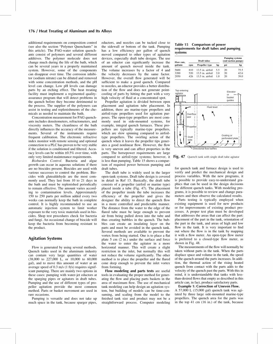
additional requirements on composition control(see also the section “Polymer Quenchants” inthis article). The PAG-water solution quench-ants consist of polymers and several differentadditives. The polymer molecule does notchange much during the life of the bath, whichcan be several years in a properly maintainedsystem. However, some of the componentscan disappear over time. The corrosion inhibi-tor (sodium nitrate) can be diluted and removedwith some concentration methods, and the pHlevel can change. Low pH levels can damageparts by an etching effect. The heat treatingfacility must implement a regimented quality-assurance program that will detect problems inthe quench before they become detrimental tothe process. The supplier of the polymers canassist in testing and replenishments of the che-micals as needed to maintain the bath.Concentration measurement for PAG quench-
ants includes densitometers, refractometers, andviscosity meters. The cleanliness of the bathdirectly influences the accuracy of the measure-ments. Several of the instruments requirefrequent calibration. The electronic refractiveindex monitor with remote sensing and optionalconnection to a PLC has proven to be very stableif the solution is conditioned and filtered. Accu-racy levels can be within ±0.5% over time, withonly very limited maintenance requirements.Bioburden Control. Bacteria and algae
growth can occur in aqueous solutions if thereare no biocides present. Biocides are used withvarious successes to control the problem. Bio-cides with glutealdehyde are the most com-monly used. They last from 10 to 21 days inthe bath and must be replenished periodicallyto remain effective. The amount varies accord-ing to contamination levels. Approximately150 to 250 parts per million added every twoweeks can normally keep the bath in completecontrol. It is highly recommended to use anautomatic injection system to limit workerexposure to the very toxic materials used in bio-cides. Shop test procedures check for bacteriaand fungi. An occasional change of biocide willkeep the bacteria from becoming resistant tothe product.
Agitation Systems
Flow is generated by using several methods.Quench tanks used in the aluminum industrycan contain very large quantities of water(38,000 to 227,000 L, or 10,000 to 60,000gal), and to move this amount of water at anaverage speed of 0.3 m/s (1 ft/s) requires signif-icant pumping. There are mainly two options inthese cases: pumping with water-jet eductors atthe sparging pipes or agitators in draft tubes.Pumping and the use of different types of pro-peller agitation provide the most commonmethod. Parts or basket movement are used inrare occasions.Pumping is versatile and does not take up
much space in the tank, because sparger pipes,
eductors, and nozzles can be tucked close tothe sidewall or bottom of the tank. Pumpinghas a low efficiency per gallon of quenchmoved compared to other types of agitationdevices, especially draft tube designs. The useof an eductor can significantly increase theamount of quench moved inside the tank.The volume increases by a factor of 4 andthe velocity decreases by the same factor.However, the overall flow generated will besufficient to make a good quench. Comparedto nozzles, an eductor provides a better distribu-tion of the flow and does not generate point-cooling of parts by hitting the part with a veryhigh velocity of fluid at a concentrated spot.Propeller agitation is divided between open
placement and agitation tube placement. Inaddition, there are marine-type propellers andairfoil-type propellers used for agitation pur-poses. The open-type propellers are most com-monly used in side-mounted systems, forexample, integral quench furnaces. These pro-pellers are typically marine-type propellers,which are slow spinning compared to airfoil-type propellers. The swirling action of thequench when it leaves the propeller tips gener-ates a good nonlinear flow. However, the flowis very uneven and can affect properties in theparts. The horsepower requirements are largecompared to airfoil-type systems; however, itis less than pumping. Table 15 shows a compar-ison of required power between pumping anddraft tubes.The draft tube is widely used in the larger
open-tank systems. Draft tube design is coveredin detail in Ref 13. Basically, the draft tubeconsists of a propeller (airfoil or marine type)placed inside a tube (Fig. 47). The placementof the propeller inside the tube increases theefficiency of the propeller and gives thedesigner the ability to direct the quench flowin a more controlled and predictable manner.The distance from the water to the edge of theflared tube must be large enough to preventair from being pulled down into the tube andthus creating bubbles in the quench. The bub-bles can create an insulating layer on theparts and must be avoided in the quench tank.Several methods are available to prevent thevortex from being started. One is to place a flatplate 5 cm (2 in.) under the surface and forcethe water to enter the agitator in a morehorizontal manner. This will create a slightrestriction in the inlet, but normally this willnot reduce the volume significantly. The othermethod is to place the propeller and the flaredcone deep enough to prevent the inlet vortexfrom forming.Flow modeling and parts tests are useful
tools in evaluating the proper method for gener-ating the flow and placing parts baskets in thearea of maximum flow. The use of mechanicaltank modeling can help design an agitation sys-tem, but building of models can be time-con-suming, and scaling from the model to thefinished tank size and product may not be astraightforward process. Computer modeling
for quench tank and furnace design is used toverify and predict the mechanical design andprocess variables. With the new programs, itis possible to provide easy-to-understand gra-phics that can be used in the design decisionsfor different quench tanks. With modeling pro-grams, it is possible to review and change para-meters and then observe the calculated results.Parts testing is typically employed when
existing equipment is used for new productsor for improvements of existing product pro-cesses. A proper test plan must be developedthat addresses the areas that can affect the part:placement of the part in the tank, orientation ofthe part in the tank, and areas of high and lowflow in the tank. It is very important to findout where the flow is in the tank by mappingit with a flow meter. An open-type flow meteris preferred to a closed-type flow meter, asshown in Fig. 48.The measurements of the flowwill normally be
taken without parts in the tank. When the partsdisplace space and volume in the tank, the speedof the quench around the parts increases. In addi-tion, the thermal action of the rising heatedquench from contact with the parts adds to thevelocity of the quench past the parts. With this inmind, it is understandable that tanks with less-than-desired flows that empty as described in thisarticle can, in fact, produce satisfactory parts.Example 1: Correction of Uneven Flow.
A 57,000 L (15,000 gal) quench tank was agi-tated by three large side-mounted marine-typepropellers. The quench area for the parts wasin the top 41 cm (16 in.) of the tank, because
Table 15 Comparison of powerrequirements for draft tubes and pumpingsystems
Flow rate,gal/min
Draft tubesPumping systems
(end suction pumps)
rpm Propeller type hp psi hp
5600 810 13.5 in. airfoil 5.5 20 75.53200 520 13.5 in. airfoil 2.0 20 42.62950 426 13.5 in. airfoil 1.0 20 39.0
Top enteringagitator
Elevatororbasketguides
Fluid level
Grating orperforated plateDraft
tube
Directional flow baffles
Propeller
Overflowweir
Fig. 47 Quench tank with single draft tube agitator
176 / Heat Treating of Aluminum and Its Alloys
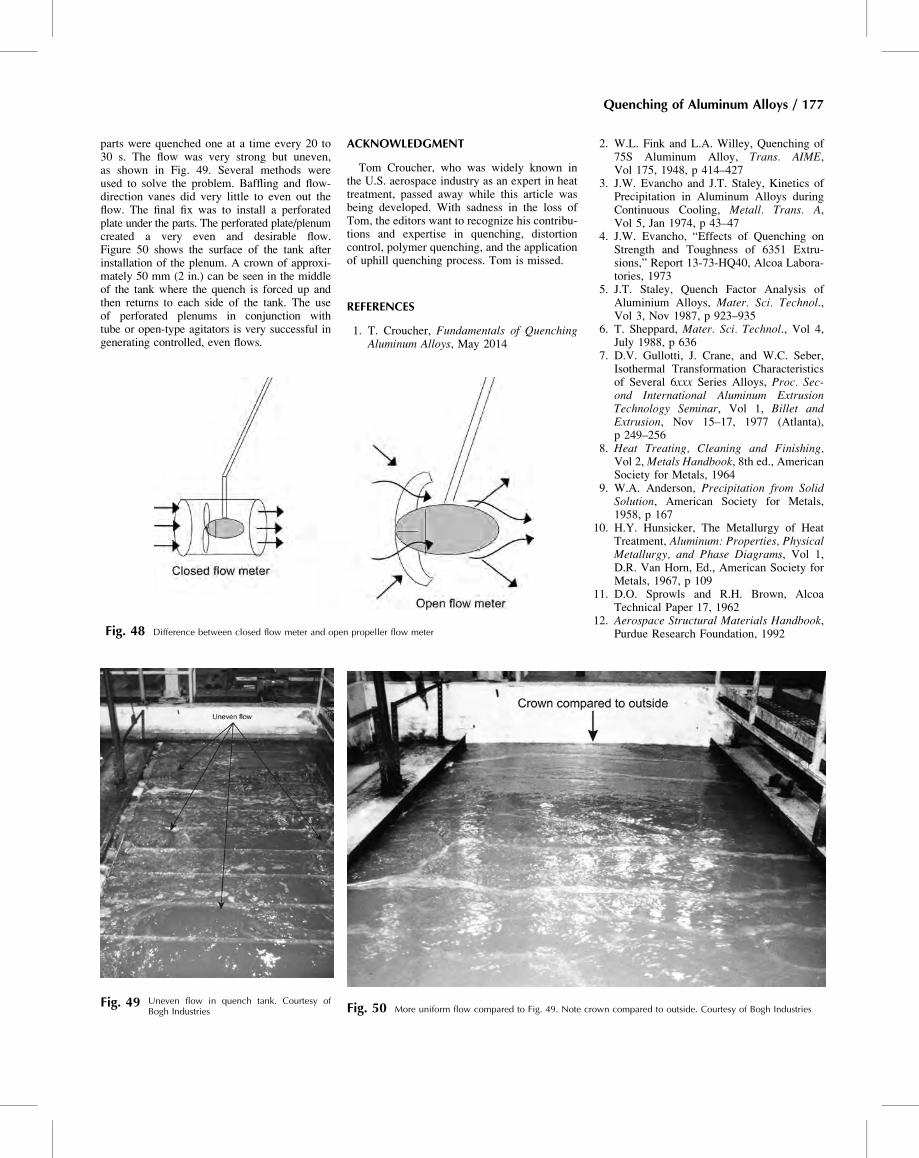
parts were quenched one at a time every 20 to30 s. The flow was very strong but uneven,as shown in Fig. 49. Several methods wereused to solve the problem. Baffling and flow-direction vanes did very little to even out theflow. The final fix was to install a perforatedplate under the parts. The perforated plate/plenumcreated a very even and desirable flow.Figure 50 shows the surface of the tank afterinstallation of the plenum. A crown of approxi-mately 50 mm (2 in.) can be seen in the middleof the tank where the quench is forced up andthen returns to each side of the tank. The useof perforated plenums in conjunction withtube or open-type agitators is very successful ingenerating controlled, even flows.
ACKNOWLEDGMENT
Tom Croucher, who was widely known inthe U.S. aerospace industry as an expert in heattreatment, passed away while this article wasbeing developed. With sadness in the loss ofTom, the editors want to recognize his contribu-tions and expertise in quenching, distortioncontrol, polymer quenching, and the applicationof uphill quenching process. Tom is missed.
REFERENCES
1. T. Croucher, Fundamentals of QuenchingAluminum Alloys, May 2014
2. W.L. Fink and L.A. Willey, Quenching of75S Aluminum Alloy, Trans. AIME,Vol 175, 1948, p 414–427
3. J.W. Evancho and J.T. Staley, Kinetics ofPrecipitation in Aluminum Alloys duringContinuous Cooling, Metall. Trans. A,Vol 5, Jan 1974, p 43–47
4. J.W. Evancho, “Effects of Quenching onStrength and Toughness of 6351 Extru-sions,” Report 13-73-HQ40, Alcoa Labora-tories, 1973
5. J.T. Staley, Quench Factor Analysis ofAluminium Alloys, Mater. Sci. Technol.,Vol 3, Nov 1987, p 923–935
6. T. Sheppard, Mater. Sci. Technol., Vol 4,July 1988, p 636
7. D.V. Gullotti, J. Crane, and W.C. Seber,Isothermal Transformation Characteristicsof Several 6xxx Series Alloys, Proc. Sec-ond International Aluminum ExtrusionTechnology Seminar, Vol 1, Billet andExtrusion, Nov 15–17, 1977 (Atlanta),p 249–256
8. Heat Treating, Cleaning and Finishing,Vol 2, Metals Handbook, 8th ed., AmericanSociety for Metals, 1964
9. W.A. Anderson, Precipitation from SolidSolution, American Society for Metals,1958, p 167
10. H.Y. Hunsicker, The Metallurgy of HeatTreatment, Aluminum: Properties, PhysicalMetallurgy, and Phase Diagrams, Vol 1,D.R. Van Horn, Ed., American Society forMetals, 1967, p 109
11. D.O. Sprowls and R.H. Brown, AlcoaTechnical Paper 17, 1962
12. Aerospace Structural Materials Handbook,Purdue Research Foundation, 1992
Fig. 49 Uneven flow in quench tank. Courtesy ofBogh Industries Fig. 50 More uniform flow compared to Fig. 49. Note crown compared to outside. Courtesy of Bogh Industries
Fig. 48 Difference between closed flow meter and open propeller flow meter
Quenching of Aluminum Alloys / 177
13. G. Totten, C. Bates, and N. Clinton, Hand-book of Quenchants and Quenching Tech-nology, ASM International, 1993
14. J.E. Hatch, Ed., Aluminum Properties andPhysical Metallurgy, American Societyfor Metals, Metals Park, OH, 1983
15. C.E. Bates, Selecting Quenchants to Maxi-mize Tensile Properties and Minimize Dis-tortion in Aluminum Parts, J. Heat Treat.,Vol 5 (No. 1), 1987, p 27–40
16. K. Speith and H. Lange, Mitt. Kaiser Wil-helm Inst. Eisenforssch, Vol 17, 1935,p 175
17. A. Rose, Arch. Eisenhullennes, Vol 13,1940, p 345
18. C.E. Bates, G.E. Totten, and R.J. Brenner,Heat Treating, Vol 4, ASM Handbook,ASM International, 1991, p 51
19. “Heat Treatment of Wrought AluminumAlloys,” AMS 2770, SAE International,Warrendale, PA
20. T. Croucher and M.D. Schuler, Met. Eng.Q., Aug 1970
21. R.H. Lauderdale, “Evaluation of Quench-ing Media for Aluminum Alloys,” MDR6-18002, Boeing, March 1967
22. E.A. Lauchner and B.O. Smith, “Evalua-tion of UconW Quenching,” NOR 69-65,Northrop Corporation, May 1969
23. T.R. Croucher, Applying Synthetic Quench-ants to High Strength Alloy Heat Treatment,Met. Eng. Q., May 1971
24. T.R. Croucher, Synthetic Quenchants Elim-inate Distortion, Met. Prog., Nov 1973
25. S. Chaudhury and D. Apelian, FluidizedBed Heat Treatment of Cast Al Alloys,Proc. John Campbell Symposium, TMSAnnual Meeting (California), 2005, p 283
26. S. Chaudhury and D. Apelian, Effect ofRapid Heating on Solutionizing Character-istics of Al-Si-Mg Alloy Using a FluidizedBed, Metall. Mater. Trans. A, Vol 37,2006, p 763–778
27. J. Keist, D. Dingmann, and C. Bergman,Fluidized Bed Quenching: Reducing Resid-ual Stresses and Distortion, Proc. 23rd HeatTreating Society Conference (Pittsburgh,PA), 2005, p 263–270
28. M. Avrami, Kinetics of Phase Change I,J. Chem. Phys., Vol 7, Feb 1939, p 1103–1112
29. M. Avrami, Kinetics of Phase Change II, J.Chem. Phys., Vol 8, Feb 1940, p 212–224
30. J.W. Cahn, Acta Metall., Vol 4, 1956,p 449–459
31. R.J. Flynn and J.S. Robinson, The Applica-tion of Advances in Quench Factor Analy-sis Property Prediction to the HeatTreatment of 7010 Aluminium Alloy, J.Mater. Process. Technol., Vol 153–154,2004, p 674–680
32. G.P. Dolan and J.S. Robinson, ResidualStress Reduction in 7175-T73, 6061-T6,and 2017A-T4 Aluminum Alloys UsingQuench Factor Analysis, J. Mater.Process. Technol., Vol 153–154, 2004,p 346–351
33. G.P. Dolan, J.S. Robinson, and A.J. Morris,Quench Factors and Residual Stress
Reduction in 7175-T73 Plate, Proc. Mate-rials Solution Conference (Indianapolis,IN), ASM International, 2001, p 213–218
34. D.D. Hall and I. Mudawar, Optimization ofQuench History of Aluminum Parts forSuperior Mechanical Properties, Int. J.Heat Mass Transf., Vol 39 (No. 1), 1996,p 81–95
35. L.K. Ives et al., “Processing/Microstructure/Property Relationships in 2024 AluminumAlloy Plates,” National Bureau of StandardsTechnical Report NBSIR 83-2669, U.S.Department of Commerce, Jan 1983
36. L. Swartzendruber et al., “NondestructiveEvaluation of Nonuniformities in 2219Aluminum Alloy Plate—Relationship toProcessing,” National Bureau of Stan-dards Technical Report NBSIR 80-2069,U.S. Department of Commerce, Dec1980
37. J. Newkirk and D. MacKenzie, The JominyEnd Quench for Light-Weight AlloyDevelopment, J. Mater. Eng. Perform.,Vol 9 (No. 4), 2000, p 408–441
38. P.M. Kavalco, L.C.F. Canale, and G.E. Tot-ten, Quenching of Aluminum Alloys: Prop-erty Prediction by Quench Factor Analysis,Heat Treat. Prog., May/June, 2009
39. K.R. Van Horn, J. Met., March 1953,p 405–422
40. P. Archambault et al., Heat Treatment1976, Proc. 16th Int. Heat Treatment Con-ference, Book 181, Metals Society, London,1976, p 105–109, 219, 220
178 / Heat Treating of Aluminum and Its Alloys