Embed Size (px)
Citation preview
1
Quench degradation limit of multifilamentary Ag/Bi2Sr2CaCu2Ox
round wires
Liyang Ye1,2, Pei Li1, Tengming Shen1, *, Justin Schwartz2, *
1Magnet Systems Department, Fermi National Accelerator Laboratory, Batavia, IL 60510, USA
2Department of Materials Science and Engineering, North Carolina State University, Raleigh, NC
27695, USA
*[email protected] and [email protected]
Abstract
Understanding safe operating limits of composite superconducting wires is important for the design of
superconducting magnets. Here we report measurements of quench-induced critical current density Jc
degradation in commercial Ag/Bi2Sr2CaCu2Ox (Bi-2212) round wires using heater-induced quenches
at 4.2 K in self magnetic field that reveal a general degradation behavior. Jc degradation strongly
depends on the local hot spot temperature Tmax, and is nearly independent of operating current, the
temperature gradient along the conductor dTmax/dx, and the temperature rising rate dTmax/dt. Both Jc
and n value (where n is an index of the sharpness of the superconductor-to-normal transition) exhibit
small but irreversible degradation when Tmax exceeds 400-450 K, and large degradation occurs when
Tmax exceeds 550 K. This behavior was consistently found for a series of Bi-2212 wires with widely
variable wire architectures and porosity levels in the Bi-2212 filaments, including a wire processed
using a standard partial melt processing and in which Bi-2212 filaments are porous, an overpressure
processed wire in which Bi-2212 filaments are nearly porosity-free and that has a Jc(4.2 K, self field)
exceeding 8000 A/mm2, and a wire that has nearly no filament to filament bridges after reaction.
Microstructural observations of degraded wires reveal cracks in the Bi-2212 filaments perpendicular
to the wire axis, indicating that the quench-induced Ic degradation is primarily driven by strain. These
results further suggest that the quench degradation temperature limit depends on the strain state of Bi-
2212 filaments and this dependence shall be carefully considered when engineering a high-field Bi-
2212 magnet.
FERMILAB-16-216-TD ACCEPTED
Operated by Fermi Research Alliance, LLC under Contract No. De-AC02-07CH11359 with the United States Department of Energy.
2
1. Introduction
Quenching poses significant risks to the operation of superconducting magnets such as those
in nuclear magnetic resonance (NMR) systems and particle accelerators. Without effective
quench protection, magnets are at risk of permanent degradation, and the risk generally
increases as the magnet operating current density and stored energy increase. It is therefore
important to understand the quench degradation behavior and limit of superconducting
composite wires, and equally importantly, to understand degradation mechanisms in order to
operate magnets within safe limits. Moreover, it is also interesting to examine whether
degradation limits change with conductor design, heat treatment, and operations.
During a quench, the local temperature inside a superconducting magnet winding rises at a
rate dTmax/dt roughly proportional to J2, where Tmax is the local hot spot temperature and J
the operating current density of superconducting wire. To protect Nb-Ti and Nb3Sn magnets
against quench-induced damages, the Tmax is typically kept below 150 K, or more
aggressively, 350 K. This design criterion may not apply to high temperature
superconducting conductors such as Ag-sheathed Bi2Sr2CaCu2Ox (Bi-2212)
multifilamentary round wires because of key differences between Bi-2212 and Nb-Ti and
Nb3Sn. For example, measurements in short samples of Bi-2212 conductors show that at 4.2
K normal zones propagate with velocities at the order of cm/s, compared to m/s for Nb-Ti
and Nb3Sn, even in strong magnetic fields up to 20 T [1, 2]. Such slow normal zone
propagation means that the local temperature gradients, dTmax/dx, in Bi-2212 would likely be
one or two orders higher. In addition, the superconducting filaments in even the best-
performing Bi-2212 wires contain a significant amount of secondary phases and porosity.
The impacts of these differences on quench degradation limits have yet been carefully
studied in the Bi-2212 round wires, especially the overpressure processed wires that exhibit
high critical current density Jc at 4.2 K and 20 T exceeding 2500 A/mm2 and engineering
critical current density Je at 4.2 K and 20 T exceeding 720 A/mm2.
Bi-2212 wires are brittle after reaction and its Jc is sensitive to strains. The non-uniform
temperature rise during a quench induces significant strain in Bi-2212 filaments and it is
widely suspected that this strain drives degradation. While the axial strain dependence of the
Jc of Bi-2212 wires has been well studied [3-6], it has been hitherto unknown what portions
3
of superconducting filaments are more prone to degradation and whether wire design and
processing can be modified to mitigate quench induced Jc degradation. For example, high Jc
in overpressure processed wires was achieved by removing porosity in powder-in-tube (PIT)
Ag/Bi-2212 wires, increasing the filament density to over 90%, as compared to 65-80% in
the wires processed using the standard partial melt processing (PMP) in 1 bar flowing O2 [7].
Yet it is unknown if quench degradation limits increase with filament density, as porosity has
been shown to serve as stress concentration sites [8]. Similar questions can be asked for other
microstructural features found in Ag/Bi-2212 wires, such as Bi-2201 grains and filament-to-
filament bridges [9-11].
Here we study the quench-induced Jc degradation behavior of a large inventory of
commercial PIT Ag/Bi-2212 wires. Wires studied include both 1 bar processed wires and
overpressure processed wires; their Jc(4.2 K, self-field) values range from 1300 A/mm2 to
over 8000 A/mm2, and corresponding Je range from 200 A/mm2 to 1500 A/mm2. We
examine the importance of Tmax, dTmax/dt, and dTmax/dx, using heater-induced quench
experiments [12, 13], on inducing Jc degradation. To investigate quench degradation
mechanism, we further examine the microstructure of degraded samples wires.
2. Experimental Approach
2.1 Samples and heat treatments
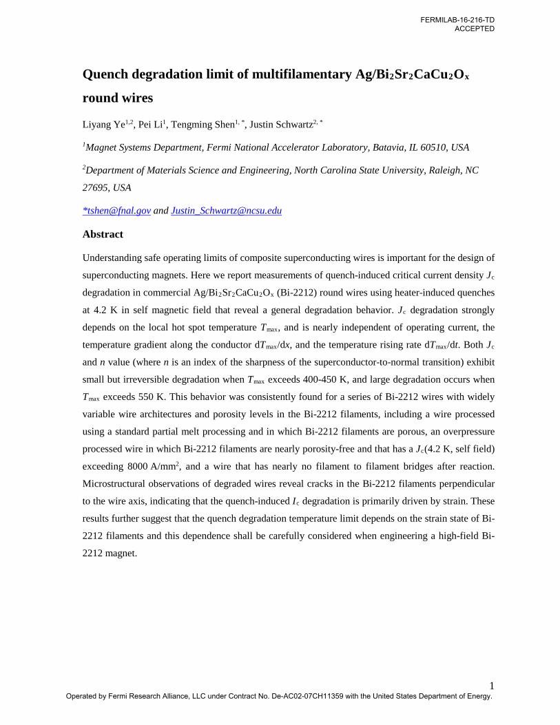
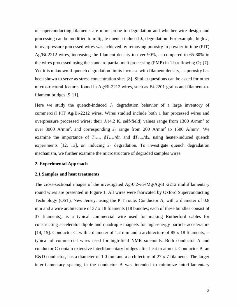
The cross-sectional images of the investigated Ag-0.2wt%Mg/Ag/Bi-2212 multifilamentary
round wires are presented in Figure 1. All wires were fabricated by Oxford Superconducting
Technology (OST), New Jersey, using the PIT route. Conductor A, with a diameter of 0.8
mm and a wire architecture of 37 x 18 filaments (18 bundles; each of these bundles consist of
37 filaments), is a typical commercial wire used for making Rutherford cables for
constructing accelerator dipole and quadruple magnets for high-energy particle accelerators
[14, 15]. Conductor C, with a diameter of 1.2 mm and a architecture of 85 x 18 filaments, is
typical of commercial wires used for high-field NMR solenoids. Both conductor A and
conductor C contain extensive interfilamentary bridges after heat treatment. Conductor B, an
R&D conductor, has a diameter of 1.0 mm and a architecture of 27 x 7 filaments. The larger
interfilamentary spacing in the conductor B was intended to minimize interfilamentary
4
bridging [16], so it is included here to determine if such bridging influences quench-induced
degradation.
Straight wires of each conductor, 8 - 16 cm in length, were heat-treated using a PMP in
flowing pure O2. The PMP included heating them from room temperature to 820 °C at
160 °C/h, holding at 820 °C for 2 hours, heating from 820 °C to 891 °C at 48 °C/h, holding at
891 °C for 0.2 hour, cooling to 881 °C at 10 °C/h, further cooling to 835 °C at 2.5 °C/h,
holding at 835 °C for 48 hour, and then quickly cooling to room temperature. To evaluate the
importance of porosity on quench degradation, conductor A was also processed using
overpressure partial-melt processing (OPMP) in a mixed gas of Ar and O2 at a gas pressure
up to 100 bar. During both heat treatments, the oxygen partial pressure was maintained at 1
bar. The density of the filaments in overpressure-processed wires increased to >95% when
the gas pressure applied was greater than 25 bar, as compared to 65-80% for wires processed
at 1 bar.
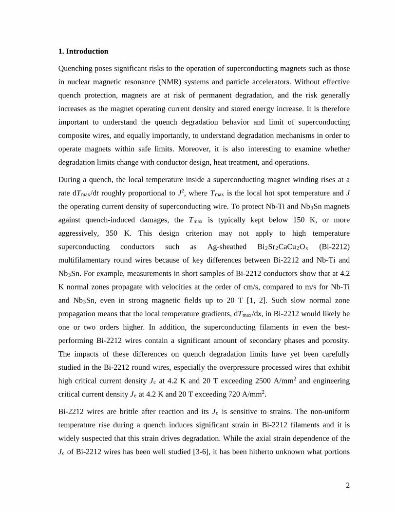
2.2 Test protocols and instrumentations
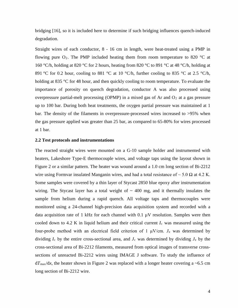
The reacted straight wires were mounted on a G-10 sample holder and instrumented with
heaters, Lakeshore Type-E thermocouple wires, and voltage taps using the layout shown in
Figure 2 or a similar pattern. The heater was wound around a 1.0 cm long section of Bi-2212
wire using Formvar insulated Manganin wires, and had a total resistance of ~ 5.0 Ω at 4.2 K.
Some samples were covered by a thin layer of Stycast 2850 blue epoxy after instrumentation
wiring. The Stycast layer has a total weight of ~ 400 mg, and it thermally insulates the
sample from helium during a rapid quench. All voltage taps and thermocouples were
monitored using a 24-channel high-precision data acquisition system and recorded with a
data acquisition rate of 1 kHz for each channel with 0.1 µV resolution. Samples were then
cooled down to 4.2 K in liquid helium and their critical current Ic was measured using the
four-probe method with an electrical field criterion of 1 μV/cm. Je was determined by
dividing Ic by the entire cross-sectional area, and Jc was determined by dividing Je by the
cross-sectional area of Bi-2212 filaments, measured from optical images of transverse cross-
sections of unreacted Bi-2212 wires using IMAGE J software. To study the influence of
dTmax/dx, the heater shown in Figure 2 was replaced with a longer heater covering a ~6.5 cm
long section of Bi-2212 wire.
5
Quench degradation experiments followed the protocols established in earlier studies [1, 2,
12, 13, 15, 17-20]. While carrying a steady-state transport current, the sample received a heat
pulse of variable duration and amplitude, creating a local hotspot resulting in a maximum
temperature Tmax and either thermal runaway or recovery. After cooling to 4.2 K and re-
measuring Ic, Tmax was raised gradually with a 20-50 K step via increased heater pulse
duration or amplitude until Ic degradation was found. Table 1 summarizes samples studied
with their heat treatment, heater set-up, and transport current It.
Table 1 List of samples investigated
Sample No. Conductor
Pressure during
processing
Length of wire covered by the
heater
Epoxy?
Je (A/mm2
)
Jc (A/mm2
) It (A)
1 A 1 bar 1.0 cm No
835
3340
100 2 A 1 bar 6.5 cm No 100 3 A 1 bar 6.5 cm No 10 4 A 1 bar 1.0 cm No 200 5 A 1 bar 1.0 cm Yes 200 6 B 1 bar 1.0 cm No 204
1360
150
7 B 1 bar 1.0 cm Yes 150 8 C 1 bar 1.0 cm No 893 3572 200 9 A 100 bar 1.0 cm No 1678 8134 200 10 A 100 bar 1.0 cm No 200
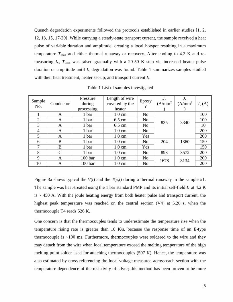
Figure 3a shows typical the V(t) and the T(x,t) during a thermal runaway in the sample #1.
The sample was heat-treated using the 1 bar standard PMP and its initial self-field Ic at 4.2 K
is ~ 450 A. With the joule heating energy from both heater pulse and transport current, the
highest peak temperature was reached on the central section (V4) at 5.26 s, when the
thermocouple T4 reads 526 K.
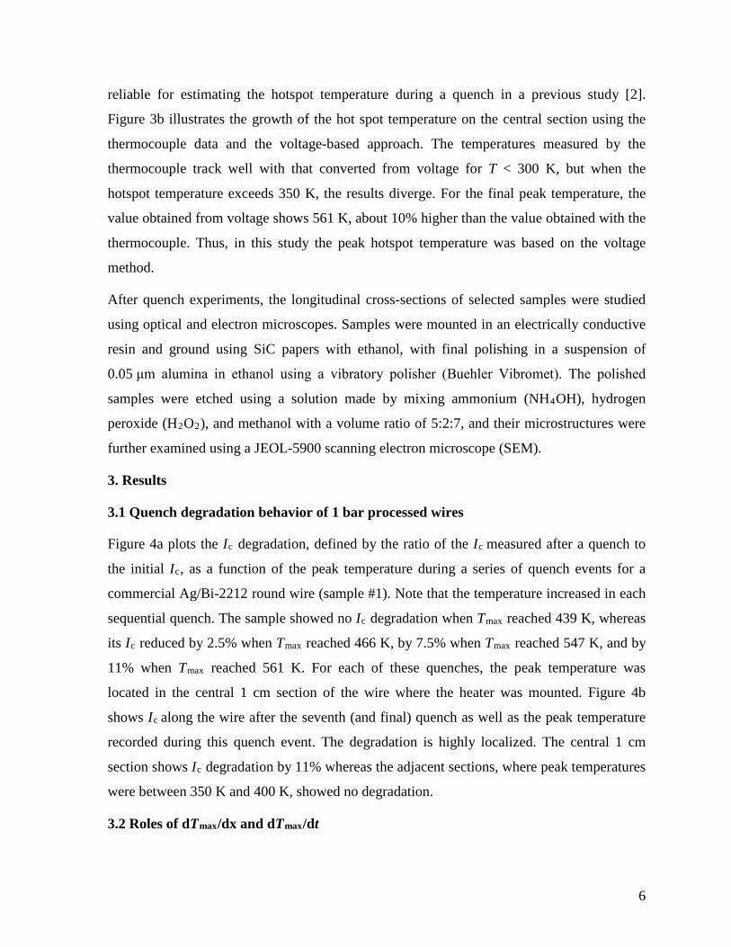
One concern is that the thermocouples tends to underestimate the temperature rise when the
temperature rising rate is greater than 10 K/s, because the response time of an E-type
thermocouple is ~100 ms. Furthermore, thermocouples were soldered to the wire and they
may detach from the wire when local temperature exceed the melting temperature of the high
melting point solder used for attaching thermocouples (597 K). Hence, the temperature was
also estimated by cross-referencing the local voltage measured across each section with the
temperature dependence of the resistivity of silver; this method has been proven to be more
6
reliable for estimating the hotspot temperature during a quench in a previous study [2].
Figure 3b illustrates the growth of the hot spot temperature on the central section using the
thermocouple data and the voltage-based approach. The temperatures measured by the
thermocouple track well with that converted from voltage for T < 300 K, but when the
hotspot temperature exceeds 350 K, the results diverge. For the final peak temperature, the
value obtained from voltage shows 561 K, about 10% higher than the value obtained with the
thermocouple. Thus, in this study the peak hotspot temperature was based on the voltage
method.
After quench experiments, the longitudinal cross-sections of selected samples were studied
using optical and electron microscopes. Samples were mounted in an electrically conductive
resin and ground using SiC papers with ethanol, with final polishing in a suspension of
0.05 μm alumina in ethanol using a vibratory polisher (Buehler Vibromet). The polished
samples were etched using a solution made by mixing ammonium (NH4OH), hydrogen
peroxide (H2O2), and methanol with a volume ratio of 5:2:7, and their microstructures were
further examined using a JEOL-5900 scanning electron microscope (SEM).
3. Results
3.1 Quench degradation behavior of 1 bar processed wires
Figure 4a plots the Ic degradation, defined by the ratio of the Ic measured after a quench to
the initial Ic, as a function of the peak temperature during a series of quench events for a
commercial Ag/Bi-2212 round wire (sample #1). Note that the temperature increased in each
sequential quench. The sample showed no Ic degradation when Tmax reached 439 K, whereas
its Ic reduced by 2.5% when Tmax reached 466 K, by 7.5% when Tmax reached 547 K, and by
11% when Tmax reached 561 K. For each of these quenches, the peak temperature was
located in the central 1 cm section of the wire where the heater was mounted. Figure 4b
shows Ic along the wire after the seventh (and final) quench as well as the peak temperature
recorded during this quench event. The degradation is highly localized. The central 1 cm
section shows Ic degradation by 11% whereas the adjacent sections, where peak temperatures
were between 350 K and 400 K, showed no degradation.
3.2 Roles of dTmax/dx and dTmax/dt
7
Figure 5a plots the reduction in Ic and the corresponding Tmax versus location along the
sample for samples #1-3 after their final quenches. Note that sample #2 and sample #3 had
the longer heater. Figure 5b plots the corresponding sequence of quenches in terms of the
reduction in Ic versus peak temperature in the central section. Despite having much smaller
dT/dx (<20 K/cm for sample #2 and #3 vs. >250 K/cm for sample #1 in the central sections),
samples #2 and #3, like sample #1, show degradation when the local hotspot temperature
exceeds 400-450 K.
A previous study shows that the rate at which the peak temperature increased did not
influence conductor degradation [13], and the results found here are in agreement with that
conclusion. In this work, the temperature increases most rapidly at lower temperature, e.g. at
400 K/s in the range of 100-200 K, whereas dT/dt is only ~50 K/s when the >500 K. While
an experiment designed to vary dT/dt at higher temperature is required to determine if dT/dt
is a secondary factor in degradation, within the range of parameters studied here, it does not
play a measureable role.
3.3 Roles of wire architectures and filament bridges
Figure 6 illustrates the quench degradation behavior for a series of wires, as shown in
Figure 1, with different architecture. Only results from samples heat-treated at 1 bar
atmospheric pressure and quenched using the shorter heater length are plotted, so the only
variables are the wire architecture, the transport current during quenching and the presence of
epoxy. Despite these differences, these samples follow a consistent trend. In short, while the
amount that Ic decreases varies from wire to wire, they all show no degradation until Tmax
reaches ~400 K, gradual degradation for 400 K < Tmax < 550 K, and a rapid decrease for Tmax
> 550 K.
3.4 Quench degradation behavior of overpressure processed, densified wires
Figure 7 compares results from two samples processed at 100 bar using OP-PMP (samples #9
and #10) and the corresponding 1 bar PMP processed sample (#4). In Figure 7a the results
are plotted as the ratio of Ic after quenching to the initial Ic as a function of peak temperature,
whereas in Figures 7b and 7c the absolute values of Ic and n-value are plotted as a function of
peak temperature. The onset of Ic degradation in OP processed samples is also around 450 K.
The n-value behaves similarly to the corresponding Ic.
8
3.5 Microstructure of quench degraded samples
Figures 8 and 9 show SEM images of the longitudinal cross-sections from the sample #9, a
100 bar OP processed conductor-A wire. Figure 8 is a location ~1.25 cm from the sample
center within section V2, where the peak temperature reached 350 K and Ic was not
degraded. The Bi-2212 filaments are dense with some porosity observed. No cracking or
other evidence of quenching is seen. Figure 9a is from the sample center, within section V4,
where the peak temperature reached 565 K and Ic was reduced by 40%. Cracks are clearly
seen, and their propagation was primarily perpendicular to the wire axis. Figures 9b and 9c
are higher magnification images of the two large cracks circled in Figure 9a.
Figure 10 shows an example of a more dramatic failure. Sample #10 reached a peak
temperature of 635 K and had an 80% reduction in Ic. It had a significant rupture. The image
shown was taken in the central 0.2-0.3 mm of the wire, within the section V4.
4. Discussion
4.1 Evidences for a strain-driven quench degradation mechanism
The microstructures of degraded samples clearly support that the quench-induced Ic
degradation is driven by fracture of Bi-2212 filaments due to excessive strains. The cracks
and their propagation paths as seen in Figure 9 are very similar to those reported by van der
Laan et al. [21] and by Lu and Cheggour [4, 5] in their mechanically tested and damaged
samples. Figure 11 illustrates a schematic of our experimental set-up and what occurs when
the wire experiences a quench. During a quench, temperature on Bi-2212/Ag wire rises,
whereas the G-10 sample holder and Cu leads are still at 4.2 K. Consequently, the wire
buckles and forms an arc to accommodate wire elongation and minimize the total thermal
stress. Therefore, Bi-2212 filaments are only subjected to a net tensile axial strain produced
by differences in the thermal expansion between silver and Bi-2212. Assuming that the
expansion is dominated by silver, this tensile strain for the Bi-2212 filaments can be
appropriated by
𝜀𝜀|𝐵𝐵𝐵𝐵2212 = Δ𝐿𝐿/𝐿𝐿𝑇𝑇𝑚𝑚𝑚𝑚𝑚𝑚−4.2𝐾𝐾|𝐴𝐴𝐴𝐴 - Δ𝐿𝐿/𝐿𝐿𝑇𝑇𝑚𝑚𝑚𝑚𝑚𝑚−4.2𝐾𝐾|𝐵𝐵𝐵𝐵2212
where Tmax is the local hot spot temperature and Δ𝐿𝐿/𝐿𝐿𝑇𝑇𝑚𝑚𝑚𝑚𝑚𝑚−4.2𝐾𝐾|𝐴𝐴𝐴𝐴 and Δ𝐿𝐿/𝐿𝐿𝑇𝑇𝑚𝑚𝑚𝑚𝑚𝑚−4.2𝐾𝐾|𝐵𝐵𝐵𝐵2212
the total linear expansion from 4.2 K to Tmax for silver and Bi-2212, respectively. Since the
9
thermal expansion is approximately linear above room temperature, the total expansion from
4.2 K to a Tmax above room temperature can be determined approximately from:
𝜀𝜀|𝐵𝐵𝐵𝐵2212 = (Δ𝐿𝐿/𝐿𝐿293𝐾𝐾−4.2𝐾𝐾|𝐴𝐴𝐴𝐴 - Δ𝐿𝐿/𝐿𝐿293𝐾𝐾−4.2𝐾𝐾|𝐵𝐵𝐵𝐵2212) + (𝛼𝛼𝐴𝐴𝐴𝐴,293𝐾𝐾 - 𝛼𝛼𝐵𝐵𝐵𝐵2212,293𝐾𝐾)(𝑇𝑇𝑚𝑚𝑚𝑚𝑚𝑚 −
293 𝐾𝐾)
Since Δ𝐿𝐿/𝐿𝐿293𝐾𝐾−4.2𝐾𝐾|𝐴𝐴𝐴𝐴 is 0.413%, Δ𝐿𝐿/𝐿𝐿293𝐾𝐾−4.2𝐾𝐾|𝐵𝐵𝐵𝐵2212 0.152%, 𝛼𝛼𝐴𝐴𝐴𝐴,293𝐾𝐾 18.5 x 10⁻⁶ K-1,
and 𝛼𝛼𝐵𝐵𝐵𝐵2212,293𝐾𝐾 8.3 x 10⁻⁶ K-1 along the a,b-axes of Bi-2212 grains [22]. With a Tmax of 463
K, the strain on the Bi-2212 filaments is therefore predicted as 0.434%, consistent with
measurements that indicate that the irreversible tensile strain is in the range of 0.4-0.6% [4-6,
23]. Note that the actual strain state for the Ag and Bi-2212 filaments within the composite
wire is complex, because the presence of the filaments results in plastic deformation in the
Ag matrix during the cooling from the processing peak temperature (~830 °C) to 4.2 K and
the Bi-2212 filaments also reduce the ability of silver to expand during warming [24], which
results in a tensile strain on the Bi-2212 filaments smaller than that predicted by the above
ballpark analysis. Furthermore, a more accurate analysis may consider the temperature
dependence of the silver and Bi-2212 mechanical properties. The ballpark analysis presented
here, however, does affirm that the Ic degradation during a quench is driven by the local
strain in the Bi-2212 filaments. With the temperature continuing to rise and the hot zone
spreading, the sample ruptures as seen in Figure 10. Note that the wire rupture is likely
caused by macroscopic bending caused by thermal buckling specific to the straight sample
set-up. Such sharp bending is not likely to occur in an epoxy impregnated coil winding pack.
Additional experimental evidence supports a strain-driven degradation mechanism. Figure
12a shows the dependence of Jc degradation on Tmax obtained from the sample #5. Up to 400
K, the Jc of this sample shows no degradation. With temperature rising beyond 400 K, the Jc
of the sample degrades irreversibly but interestingly, when the same sample sequentially
subjected to quenches with a lower peak temperature, its Jc shows no further degradation.
This behavior is strikingly similar to the dependence of the Jc of Bi-2212 wires on axial
strain measured by Lu and Cheggour [4, 5] using a beryllium Walters spring, which is also
shown in Figure 12b. The axial strain dependence of the Jc of Bi-2212 wires has a reversible
and irreversible behavior in that Jc is reversible within a strain window and once a conductor
is degraded, its irreversible strain limit increases.
10
4.2 Role of conductor architecture and processing on quench limits
Despite that the Ic of Bi-2212 wires depends strongly on the internal connectivity between
grains within Bi-2212 filaments and therefore also depends on processing and filament
architecture [9-11, 16], our experimental results suggest that the quench degradation limit is
fairly independent of the filament architecture, processing, and filament density. Therefore,
our findings and arguments can be extended to other commercial PIT Ag/Bi-2212 wires with
a architecture different from those invested here, such as the single-restack wires produced
by Supercon Inc., and the 121 x 18, 𝜙𝜙1.5 mm wires produced by OST. It can also be deduced
from our results that the strain dependence of Bi-2212 wires is weakly influenced by
overpressure processing and filament density; this deduction is consistent with recent results
that have shown that increasing Jc significantly via filament densification does not improve
strain-tolerance [6].
4.3 Implications for magnet design and further investigations
Our results show that the quench degradation is weakly influenced by dTmax/dx up to
250 K/cm and dTmax/dt up to 500 K/s. Tmax can therefore be used as the key parameter for
designing a magnet against quench-induced damages. The maximum hot spot temperature
Tmax during a quench can be estimated using this relationship [2, 25]:
𝛾𝛾𝛾𝛾(𝑇𝑇)𝜌𝜌𝑚𝑚(𝑇𝑇)
𝑑𝑑𝑇𝑇 =𝐴𝐴𝑚𝑚𝐴𝐴𝑐𝑐𝑐𝑐
𝐽𝐽𝑚𝑚2 𝑑𝑑𝑑𝑑∝
0
𝑇𝑇𝑚𝑚𝑚𝑚𝑚𝑚
4.2 𝐾𝐾
where 𝛾𝛾 is density and 𝛾𝛾(𝑇𝑇) specific heat averaged over the winding-cross-section, 𝜌𝜌𝑚𝑚(𝑇𝑇)
the resistivity of silver matrix, 𝐽𝐽𝑚𝑚 the current density in silver matrix, and 𝐴𝐴𝑚𝑚 the cross-
sectional area of silver, and 𝐴𝐴𝑐𝑐𝑐𝑐 the total cross-sectional area of the wire.
Our results indicate that the maximum allowable temperature during a quench can be as high
as 400 K for free standing Ag/Bi-2212 wires without being subjected to additional
electromagnetic stresses. However, as we have discussed, the maximum allowable
temperature would decrease with increasing tensile axial strain. As high field solenoids such
as those needed for >1 GHz NMR magnets are expected to work in the high stress regions
and therefore, the dependence on maximum allowable temperature on the axial stress and
strain needs to be carefully measured in magnetic fields. In a recent quench experiment on a
11
Bi-2212 coil operating in a 7 T background magnetic field, the conductor experienced a peak
temperature up to 280 K without any Ic degradation [2], with the hoop stress estimated at
60 MPa. Such dependence of quench degradation temperature limit on strain state needs to
be considered when one designs a Bi-2212 magnet, or any high-field magnet using brittle
superconductors. This is especially important for Bi-2212 high-field magnets because Ag-Bi-
2212 wires are mechanically weak [26]. To increase the maximum allowable temperature
during a quench, one can use an alloy sheath with increased modulus [17, 27], but note that
alloying may degrade the low temperature electrical and thermal properties of silver [28, 29].
Furthermore, these results, showing highly localized degradation, highlight the need for
distributed sensing within Bi-2212 magnets [30] or diagnostic tools that can accurately locate
a quench [31].
5. Summary
We have studied experimentally the quench behavior of a variety of commercial Bi-2212/Ag
round wires, including the effects of varying the pressure during PMP. The results show that
reductions in Ic due to quenching correlate primarily with Tmax rather than dTmax/dx or
dTmax/dt or conductor architecture or Jc. We show that all of the wires tested here are
resistant to degradation for Tmax < 400 K and exhibit small irreversible Ic and n-value
degradation for 400 K < Tmax < 550 K. Above 550 K, the degradation is more severe. Strong
evidence that Ic degradation is caused by the local strain in the Bi-2212 filaments is also
shown, including microstructural evidence of crack propagation and Ic(Tmax) results that
emulate Ic(strain) results on similar wires. This implies that Bi-2212 magnet design, and in
particular the design of high field Bi-2212 magnets, must consider the strain state of the wire
when assessing quench protection and safe protection limits during a quench.
Acknowledgements
This work was funded by the Office of High Energy Physics of the U.S. Department of
Energy (DOE) through Fermi Research Alliance (DE-AC02-07CH11359) and a US DOE
Early Career Award to Tengming Shen. Liyang Ye thanks a fellowship from the Joint
University-Fermilab Doctoral Program in Accelerator Physics and Technology. We are
indebted to Dan Assell and Ryan Mahoney at Fermilab for technical support and colleagues
12
at the Oxford Superconducting Technology and National High Magnetic Field Laboratory for
providing us the 27x7 wire.
List of Figures
Figure 1. Optical images of transverse cross sections of the conductors investigated.
Figure 2. Schematic diagram of the experimental set-up and a photograph of an instrumented
wire sample.
Figure 3. (a) Typical voltage and temperature versus time during a thermal runaway on
sample #1. (b) Comparison of temperature rises at the central section based upon
thermocouple readings and those converted from voltage measurements.
Figure 4. (a) Ic after quenching normalized by the initial Ic versus local peak temperature for
a series of quenches on sample #1; Q1, Q2, … Q7 refer to the sequential quenches, and (b)
Tmax and normalized Ic versus location along the wire for the final quench on sample #1.
Figure 5. (a) The peak temperature and normalized Ic versus location along the wires for
samples #1, 2 and 3. Note that samples #2 and #3 are quenched with the longer heaters. (b)
The corresponding normalized Ic versus Tmax.
Figure 6. Normalized Ic versus Tmax for samples of all three conductor architectures.
Figure 7. Comparison of (a) normalized Ic, (b) Ic and (c) n-value versus Tmax after quenching,
between the wires heat-treated in 1 bar and those overpressure processed at 100 bar.
Figure 8. SEM image of longitudinal cross-sections of a region of a 100 bar OP processed
sample that was quenched but had no Ic degradation..
Figure 9. SEM image of longitudinal cross-sections of a region of a 100 bar OP processed
sample that had a 40% reduction in Ic due to quenching. (a) Low-magnification image, and
(b, c) high-resolution images of the areas within the ovals.
Figure 10. SEM image of longitudinal cross-sections of a region of a 100 bar OP processed
sample that had an 80% reduction in Ic due to quenching.
Figure 11. Schematic diagrams that illustrate mechanical and stress states of the test sample
during a quench. (a) Initially, the sample, with its ends constrained and G-10 and Cu at 4.2 K,
13
is subjected to a compressive stress with a hotspot. (b) The sample forms an arc, minimizing
the compressive stress.
Figure 12. (a) Normalized Ic versus Tmax for sample #5 as in Figure 6 and (b)
electromechanical behavior of similar wire as reported in reported in [4, 5]
REFERENCES
[1] S. Ishmael, L. Haojun, M. White, F. Hunte, X. T. Liu, N. Mandzy, et al., "Enhanced Quench Propagation in Bi2Sr2CaCu2Ox and YBa2Cu3O7-x Coils via a Nanoscale Doped-Titania-Based Thermally Conducting Electrical Insulator," Applied Superconductivity, IEEE Transactions on, vol. 23, pp. 7201311-7201311, 2013.
[2] T. Shen, L. Ye, D. Turrioni, and P. Li, "High-field quench behavior and dependence of hot spot temperature on quench detection voltage threshold in a Bi2Sr2CaCu2Ox coil," Superconductor Science and Technology, vol. 28, p. 075014, 2015.
[3] B. Ten Haken, A. Godeke, H. J. Schuver, and H. H. J. ten Kate, "Descriptive model for the critical current as a function of axial strain in Bi-2212/Ag wires," IEEE Transactions on Magnetics, vol. 32, pp. 2720-2723, 1996.
[4] X. Lu, N. Cheggour, T. Stauffer, C. Clickner, L. Goodrich, U. Trociewitz, et al., "Electromechanical characterization of Bi-2212 strands," IEEE Transactions on Applied Superconductivity, vol. 21, pp. 3086-3089, 2011.
[5] N. Cheggour, X. Lu, T. Holesinger, T. Stauffer, J. Jiang, and L. Goodrich, "Reversible effect of strain on transport critical current in Bi2Sr2CaCu2O8+x superconducting wires: a modified descriptive strain model," Superconductor Science and Technology, vol. 25, p. 015001, 2012.
[6] A. Godeke, M. Hartman, M. Mentink, J. Jiang, M. Matras, E. Hellstrom, et al., "Critical current of dense Bi-2212 round wires as a function of axial strain," Superconductor Science and Technology, vol. 28, p. 032001, 2015.
[7] D. Larbalestier, J. Jiang, U. Trociewitz, F. Kametani, C. Scheuerlein, M. Dalban-Canassy, et al., "Isotropic round-wire multifilament cuprate superconductor for generation of magnetic fields above 30 T," Nature materials, vol. 13, p. 375, 2014.
[8] Q. V. Le, W. K. Chan, and J. Schwartz, "Two-dimensional peridynamic simulation of the effect of defects on the mechanical behavior of Bi2Sr2CaCu2Ox round wires," Superconductor Science and Technology, vol. 27, p. 115007, 2014.
[9] T. Shen, J. Jiang, F. Kametani, U. Trociewitz, D. Larbalestier, J. Schwartz, et al., "Filament to filament bridging and its influence on developing high critical current density in multifilamentary Bi2Sr2CaCu2Ox round wires," Superconductor Science and Technology, vol. 23, p. 025009, 2010.
[10] E. B. Callaway, G. Naderi, Q. Van Le, and J. Schwartz, "Statistical analysis of the relationship between electrical transport and filament microstructure in multifilamentary Bi2Sr2CaCu2Ox/Ag/Ag–Mg round wires," Superconductor Science and Technology, vol. 27, p. 044020, 2014.
[11] G. Naderi, X. Liu, W. Nachtrab, and J. Schwartz, "Understanding processing–microstructure–properties relationships in Bi2Sr2CaCu2Ox/Ag round wires and enhanced transport through saw-tooth processing," Superconductor Science and Technology, vol. 26, p. 105010, 2013.
14
[12] T. Effio, U. Trociewitz, X. Wang, and J. Schwartz, "Quench induced degradation in Bi2Sr2CaCu2O8+x tape conductors at 4.2 K," Superconductor Science and Technology, vol. 21, p. 045010, 2008.
[13] L. Ye, D. Cruciani, T. Effio, F. Hunte, and J. Schwartz, "On the causes of degradation in Bi2Sr2CaCu2O8+x round wires and coils by quenching at 4.2 K," IEEE Transactions on Applied Superconductivity, vol. 23, pp. 6400811-6400811, 2013.
[14] E. Barzi, V. Lombardo, D. Turrioni, F. J. Baca, and T. G. Holesinger, "BSCCO-2212 Wire and Cable Studies," IEEE Transactions on Applied Superconductivity, vol. 21, pp. 2335-2339, 2011.
[15] T. Shen, P. Li, J. Jiang, L. Cooley, J. Tompkins, D. McRae, et al., "High strength kiloampere Bi2Sr2CaCu2Ox cables for high-field magnet applications," Superconductor Science and Technology, vol. 28, p. 065002, 2015.
[16] F. Kametani, T. Shen, J. Jiang, C. Scheuerlein, A. Malagoli, M. D. Michiel, et al., "Bubble formation within filaments of melt-processed Bi2212 wires and its strongly negative effect on the critical current density," Superconductor Science and Technology, vol. 24, p. 075009, 2011.
[17] S. Ishmael, H. Luo, M. White, F. Hunte, X. Liu, N. Mandzy, et al., "Enhanced quench propagation in Bi2Sr2CaCu2Ox and YBa2Cu3O7-x coils via a nanoscale doped-titania-based thermally conducting electrical insulator," IEEE Transactions on Applied Superconductivity, vol. 23, 2013.
[18] H. Song and J. Schwartz, "Stability and quench behavior of coated conductor at 4.2 K, self-field," IEEE Transactions on Applied Superconductivity, vol. 19, pp. 3735-3743, 2009.
[19] U. P. Trociewitz, B. Czabaj, S. Hong, Y. Huang, D. C. Knoll, D. C. Larbalestier, et al., "Quench studies on a layer-wound Bi2Sr2CaCu2Ox/AgX coil at 4.2 K," Superconductor Science and Technology, vol. 21, p. 025015, 2008.
[20] Y. Yang, E. A. Young, I. Falorio, W. O. Bailey, C. M. Friend, A. Twin, et al., "Quench characteristics of Bi2212 solenoid insert coils in background field up to 20 T," IEEE Transactions on Applied Superconductivity, vol. 21, pp. 2432-2435, 2011.
[21] D. Van der Laan, H. Van Eck, B. Haken, H. Kate, and J. Schwartz, "Strain effects in high temperature superconductors investigated with magneto-optical imaging," IEEE Transactions on Applied Superconductivity, vol. 13, pp. 3534-3539, 2003.
[22] J. Ekin, Experimental Techniques for Low-Temperature Measurements : Cryostat Design, Material Properties and Superconductor Critical-Current Testing: OUP Oxford, 2006.
[23] R. Bjoerstad, C. Scheuerlein, M. Rikel, A. Ballarino, L. Bottura, J. Jiang, et al., "Strain induced irreversible critical current degradation in highly dense Bi-2212 round wire," Superconductor Science and Technology, vol. 28, p. 062002, 2015.
[24] Y. Iwasa, Case studies in superconducting magnets: Design and Operational Issues: Springer US, 2010.
[25] M. N. Wilson, Superconducting magnets: Clarendon Press Oxford, 1983. [26] P. Li, Y. Wang, A. Godeke, L. Ye, G. Flanagan, and T. Shen, "Thermal-Mechanical
Properties of Epoxy-Impregnated Bi-2212/Ag Composite," IEEE Transactions on Applied Superconductivity, vol. 25, pp. 1-4, 2015.
[27] A. Kajbafvala, W. Nachtrab, T. Wong, and J. Schwartz, "Bi2Sr2CaCu2O8+x round wires with Ag/Al oxide dispersion strengthened sheaths: microstructure–properties
15
relationships, enhanced mechanical behavior and reduced Cu depletion," Superconductor Science & Technology, vol. 27, p. 095001, 2014.
[28] P. Li, L. Ye, J. Jiang, and T. Shen, "RRR and thermal conductivity of Ag and Ag-0.2 wt.%Mg alloy in Ag/Bi-2212 wires," IOP Conference Series: Materials Science and Engineering, vol. 102, p. 012027, 2015.
[29] D. R. Smith and F. Fickett, "Low-temperature properties of silver," Journal Of Research-National Institute Of Standards And Technology, vol. 100, pp. 119-119, 1995.
[30] W. K. Chan, G. Flanagan, and J. Schwartz, "Spatial and temporal resolution requirements for quench detection in (RE)Ba2Cu3Ox magnets using Rayleigh-scattering-based fiber optic distributed sensing," Superconductor Science and Technology, vol. 26, p. 105015, 2013.
[31] M. Marchevsky, G. Sabbi, H. Bajas, and S. Gourlay, "Acoustic emission during quench training of superconducting accelerator magnets," Cryogenics, vol. 69, pp. 50-57, 2015.
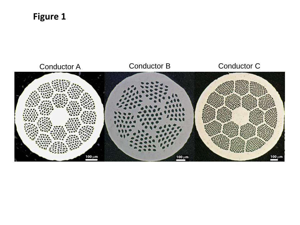
Figure 1
Conductor A Conductor B Conductor C
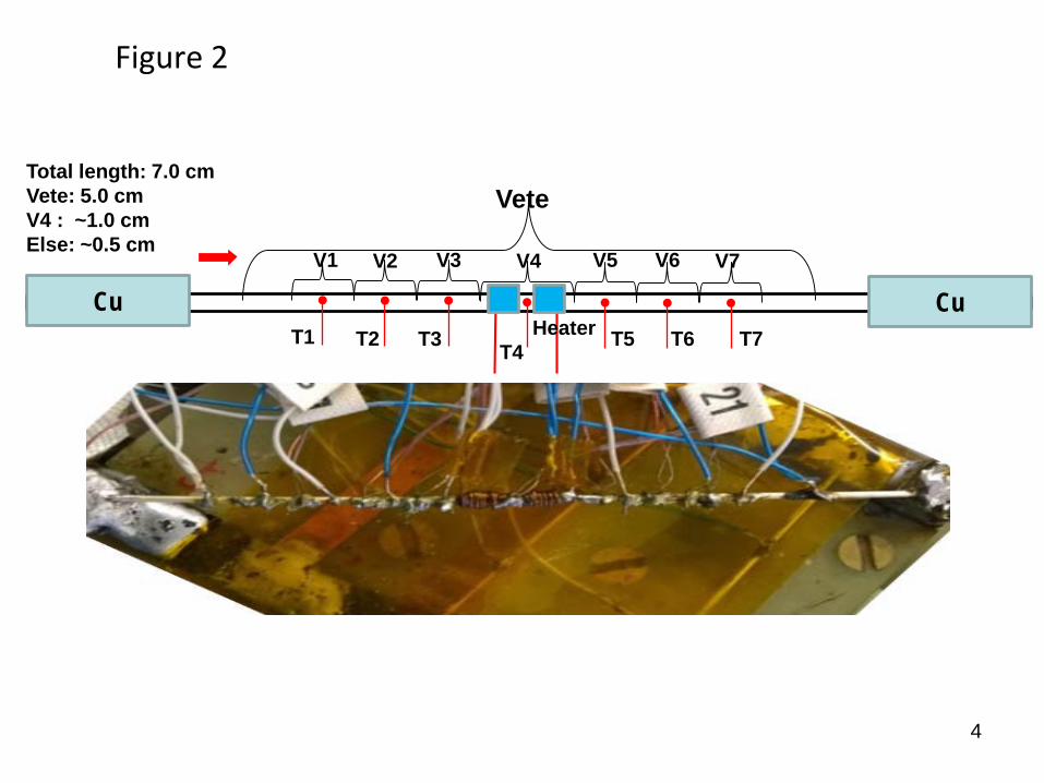
Figure 2
4
Total length: 7.0 cmVete: 5.0 cmV4 : ~1.0 cmElse: ~0.5 cm
Vete
V1
HeaterT1 T2 T3 T4 T5 T6 T7
V2 V4 V5 V6 V7V3
Cu Cu
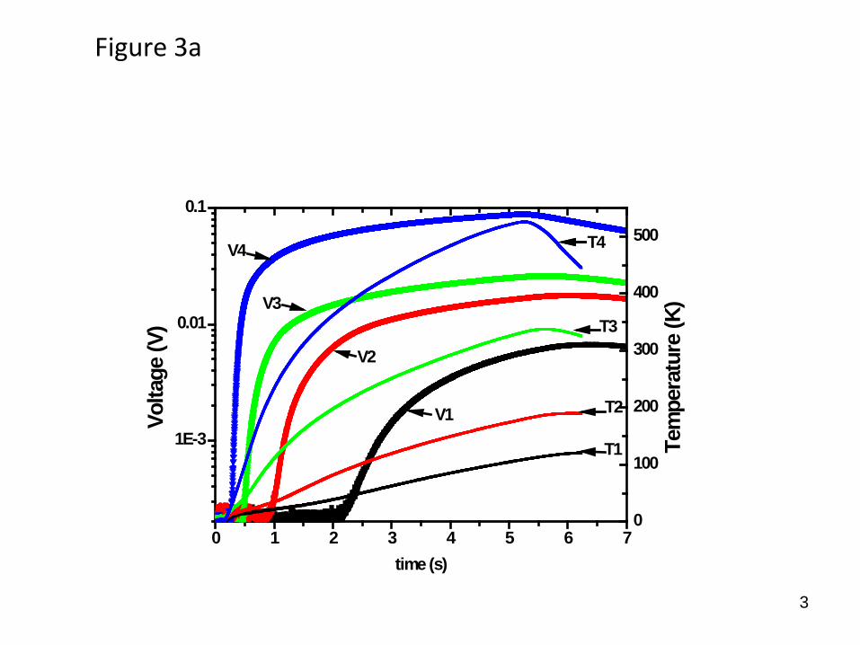
Figure 3a
3
0 1 2 3 4 5 6 7
1E-3
0.01
0.1
T1
T2
T3
T4
V1
V3
V2
Volta
ge (V
)
time (s)
V4
0
100
200
300
400
500
Tem
pera
ture
(K)
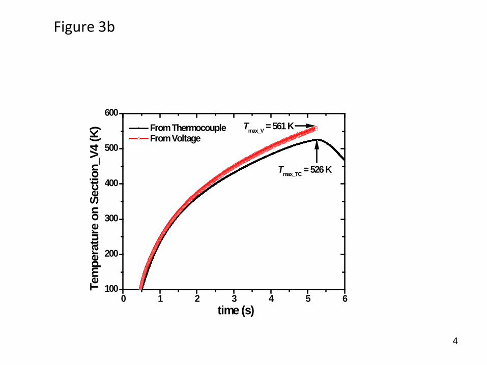
Figure 3b
4
0 1 2 3 4 5 6100
200
300
400
500
600
Tmax_TC = 526 K
From Thermocouple From Voltage
Tem
pera
ture
on
Sect
ion_
V4 (K
)
time (s)
Tmax_V = 561 K
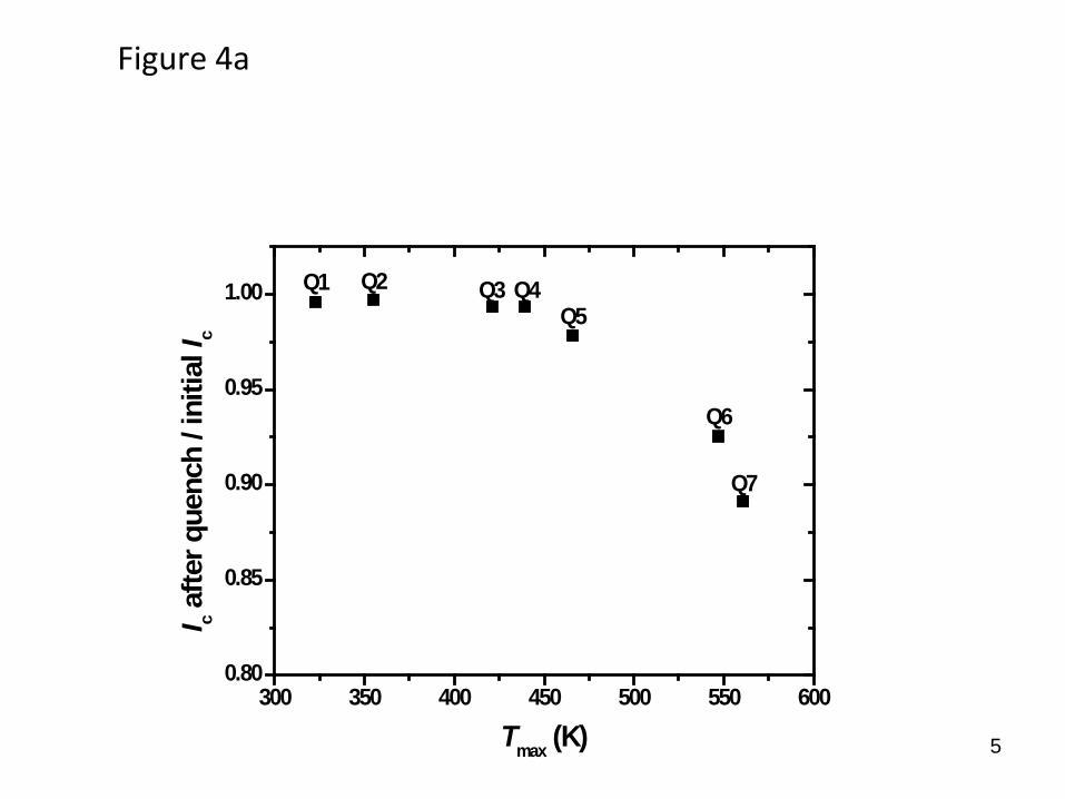
Figure 4a
5
300 350 400 450 500 550 6000.80
0.85
0.90
0.95
1.00
Q7
Q5
Q6
Q4Q3Q2
I c afte
r que
nch
/ ini
tial I
c
Tmax (K)
Q1
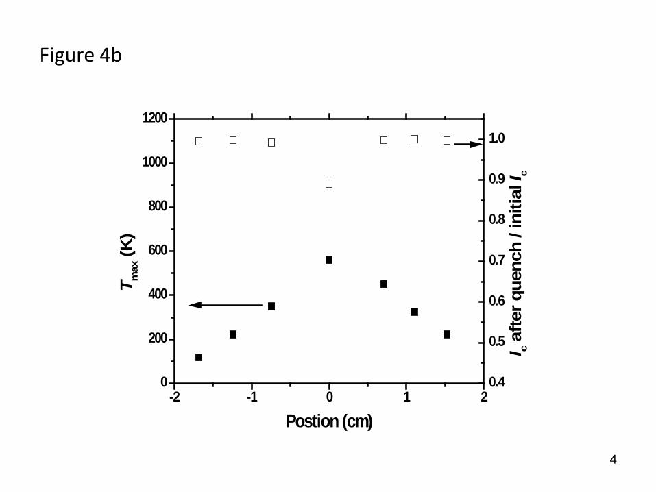
Figure 4b
4
-2 -1 0 1 20
200
400
600
800
1000
1200
T max
(K)
Postion (cm)
0.4
0.5
0.6
0.7
0.8
0.9
1.0
I c afte
r que
nch
/ ini
tial I
c
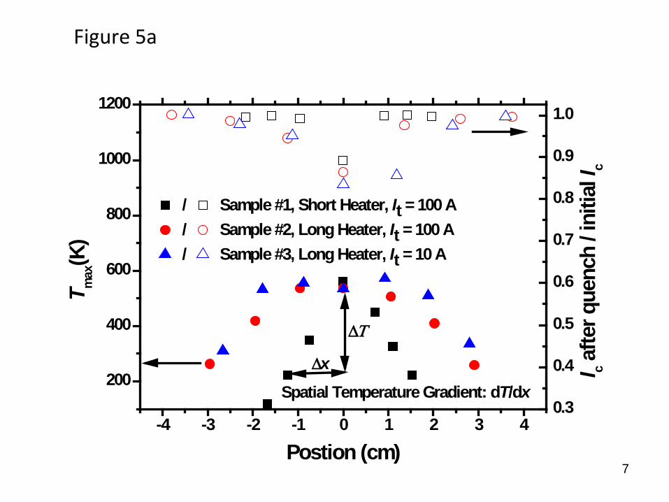
Figure 5a
7
-4 -3 -2 -1 0 1 2 3 4
200
400
600
800
1000
1200
/ Sample #1, Short Heater, It = 100 A/ Sample #2, Long Heater, It = 100 A/ Sample #3, Long Heater, It = 10 A
T m
ax(K
)
Postion (cm)
∆xSpatial Temperature Gradient: dT/dx
∆Τ
0.3
0.4
0.5
0.6
0.7
0.8
0.9
1.0
I c afte
r que
nch
/ ini
tial I
c
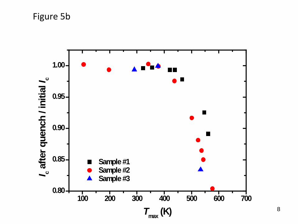
Figure 5b
8
100 200 300 400 500 600 7000.80
0.85
0.90
0.95
1.00
I c a
fter q
uenc
h / i
nitia
l Ic
Tmax (K)
Sample #1 Sample #2 Sample #3
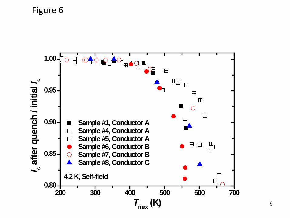
Figure 6
9
200 300 400 500 600 7000.80
0.85
0.90
0.95
1.00
Sample #1, Conductor A Sample #4, Conductor A Sample #5, Conductor A Sample #6, Conductor B Sample #7, Conductor B Sample #8, Conductor C
I c afte
r que
nch
/ ini
tial I
c
Tmax (K)
4.2 K, Self-field
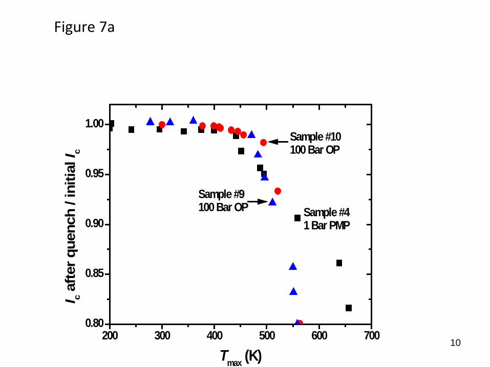
Figure 7a
10200 300 400 500 600 700
0.80
0.85
0.90
0.95
1.00
Sample #9100 Bar OP Sample #4
1 Bar PMP
Sample #10100 Bar OP
I c afte
r que
nch
/ ini
tial I
c
Tmax (K)
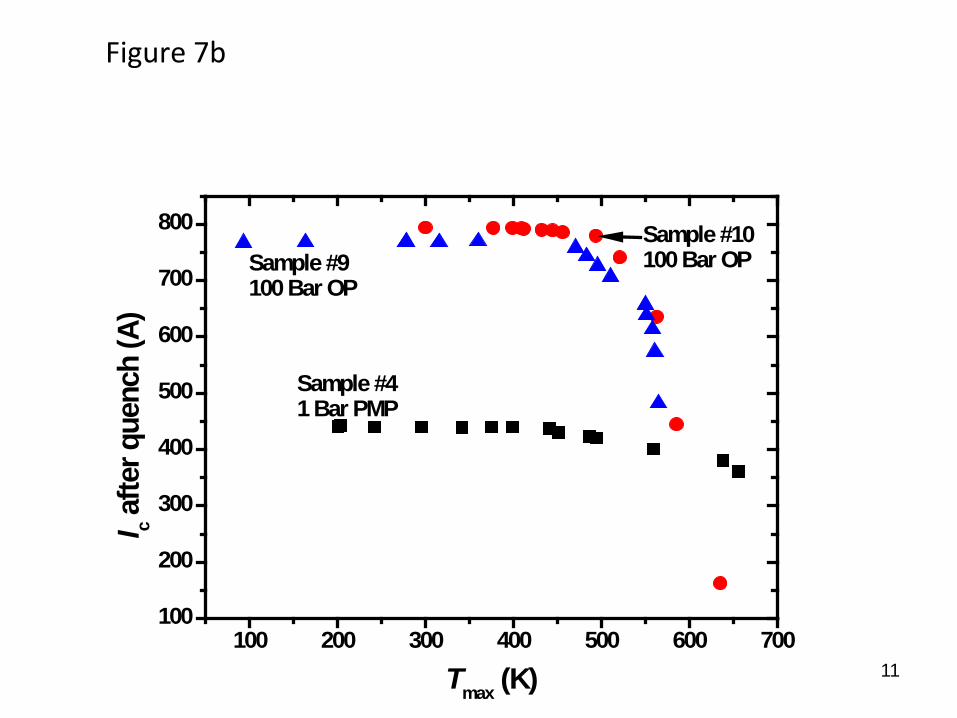
Figure 7b
11100 200 300 400 500 600 700
100
200
300
400
500
600
700
800
Sample #10100 Bar OP
Sample #41 Bar PMP
Sample #9100 Bar OP
I c afte
r que
nch
(A)
Tmax (K)
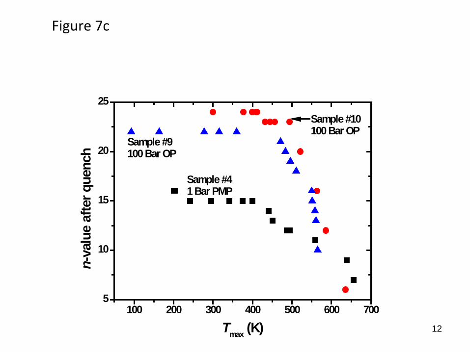
Figure 7c
12
100 200 300 400 500 600 7005
10
15
20
25
Sample #9100 Bar OP
Sample #41 Bar PMP
Sample #10100 Bar OP
n-va
lue
afte
r que
nch
Tmax (K)
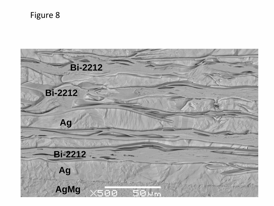
Figure 8
Bi-2212
Ag
AgMg
Bi-2212
Bi-2212
Ag
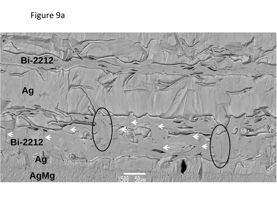
Figure 9a
Bi-2212
AgMg
Ag
Ag
Bi-2212
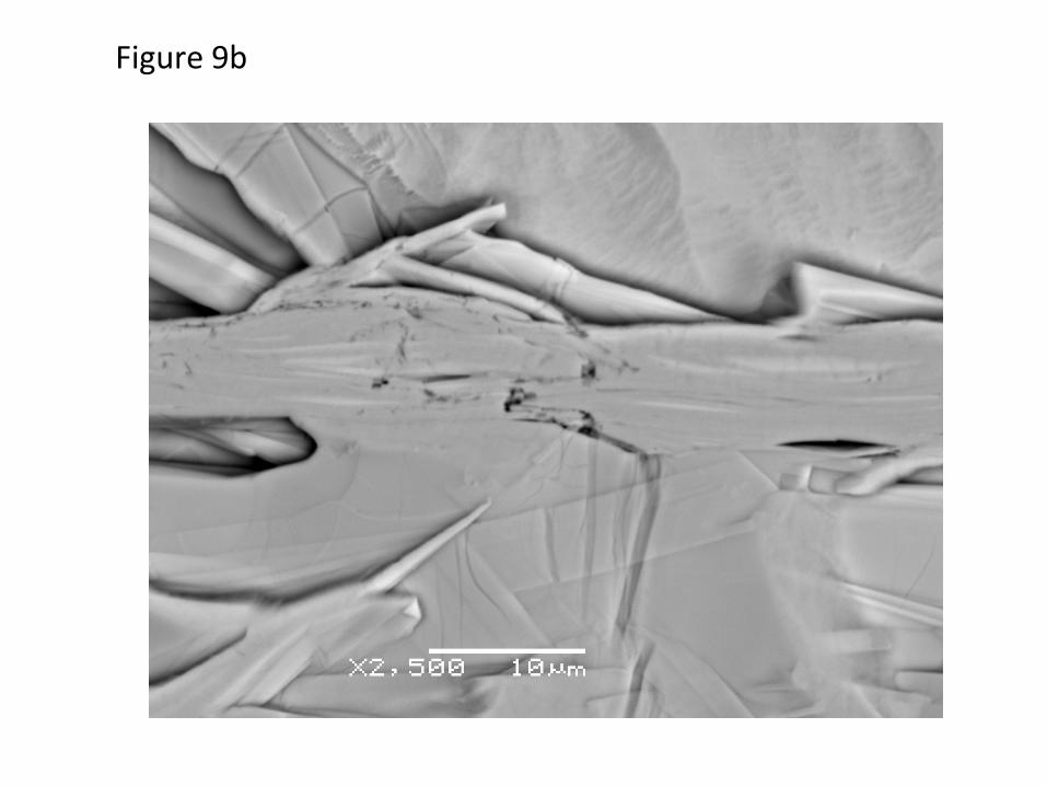
Figure 9b
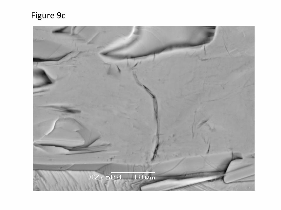
Figure 9c
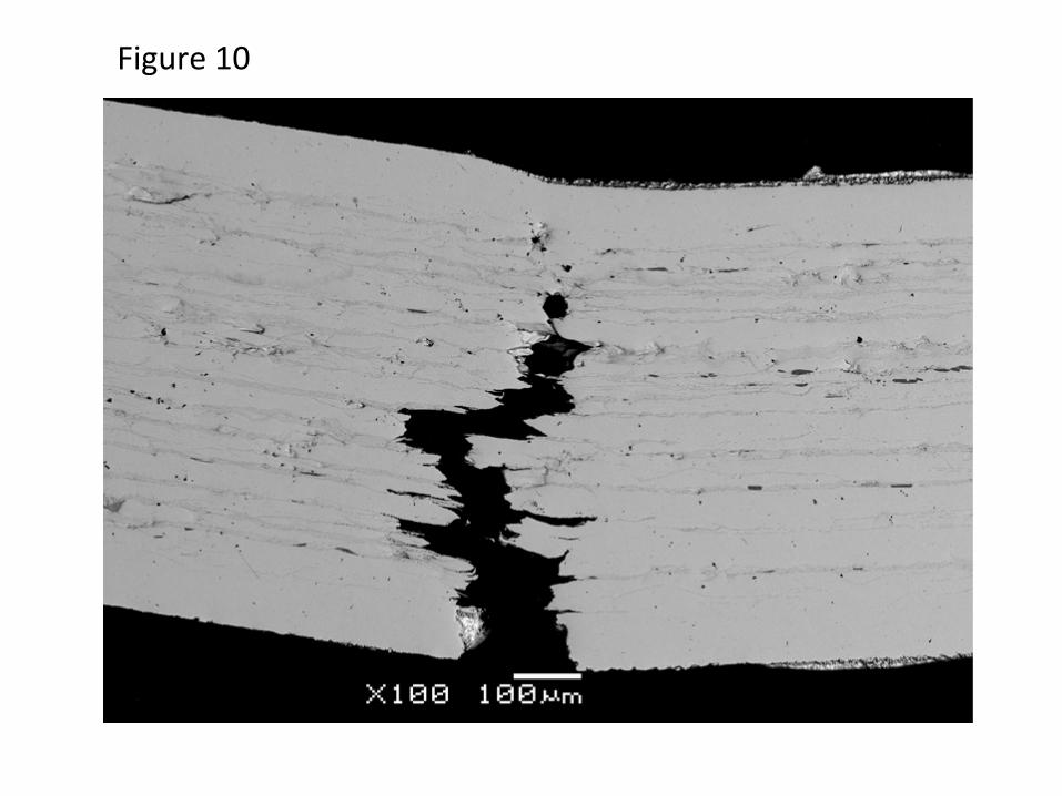
Figure 10
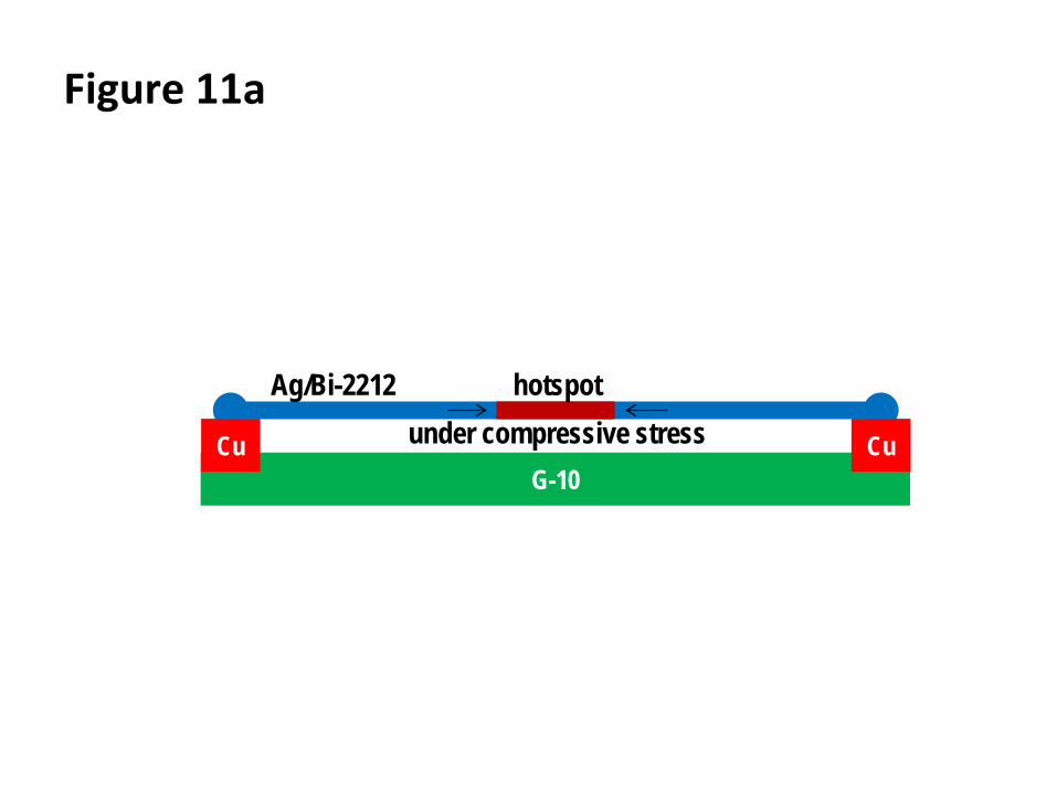
Figure 11a
G-10Cu Cu
Ag/Bi-2212under compressive stress
hotspot
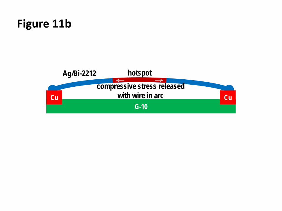
Figure 11b
G-10Cu Cu
Ag/Bi-2212compressive stress released
with wire in arc
hotspot
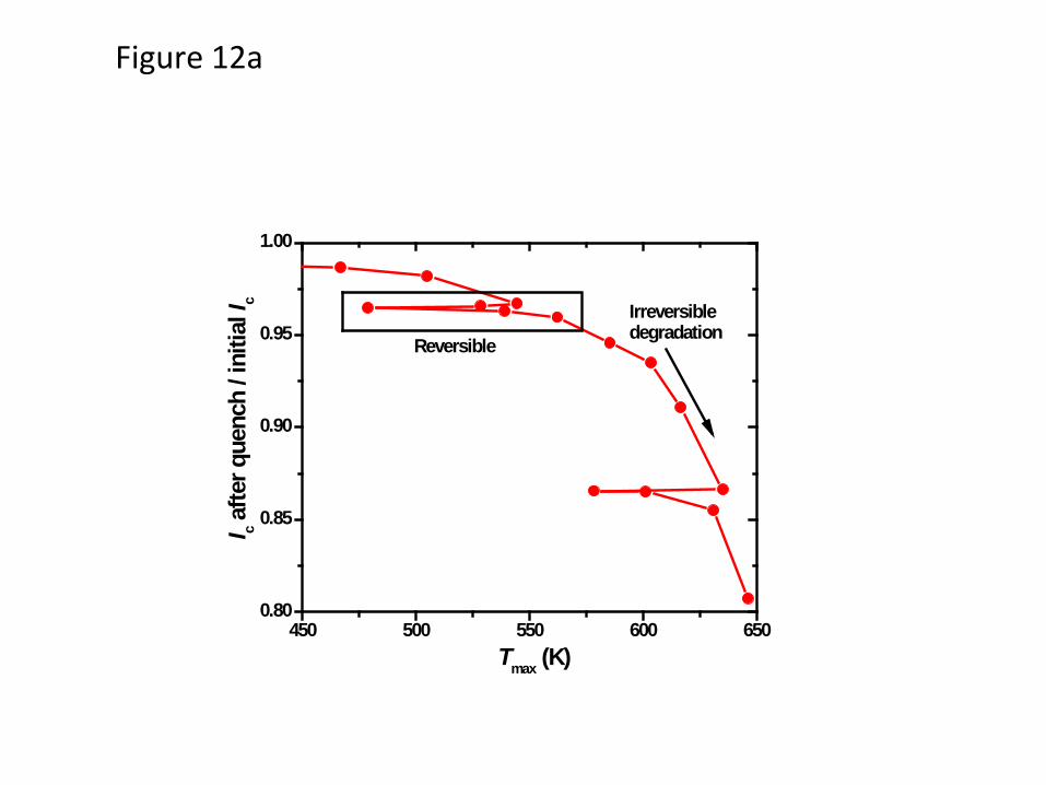
Figure 12a
450 500 550 600 6500.80
0.85
0.90
0.95
1.00
Reversible
I c afte
r que
nch
/ ini
tial I
c
Tmax (K)
Irreversible degradation
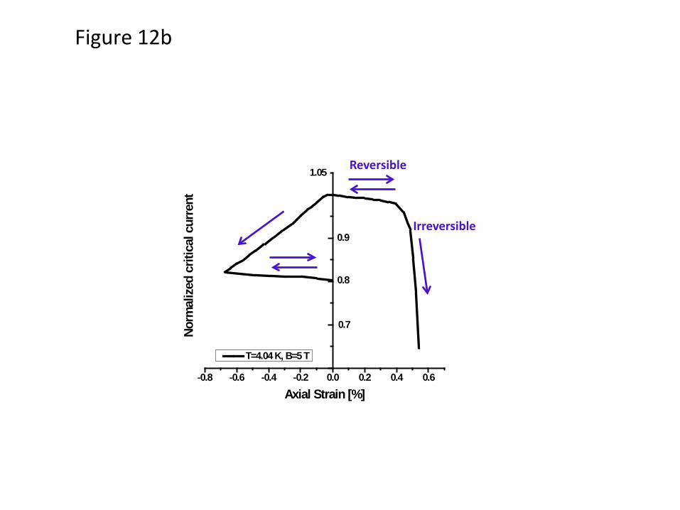
Figure 12b
-0.8 -0.6 -0.4 -0.2 0.0 0.2 0.4 0.6
Norm
aliz
ed c
ritic
al c
urre
nt1.05
0.9
0.7
Axial Strain [%]
T=4.04 K, B=5 T
0.8
Reversible
Irreversible