Embed Size (px)
Citation preview
1. Project BasicsLocation: Leicester, EnglandLatitude/Longitude: 52°37'N/1˚08'W207' elevationHDD, CDD; annual precipitation: ?Building type: Educational/
LaboratorySquare footage/ stories: 10,000m2
(100,000 s.f.)/2–4 storiesCompletion date: 13 August 1993Client: de Montfort UniversityDesign team:Architects: Short Ford Associates—
Alan Short & Brian FordEngineers: Max Fordham Associates—
Max Fordham & Randall Thomas
Queen’s Building, DeMontfort University
Image 4
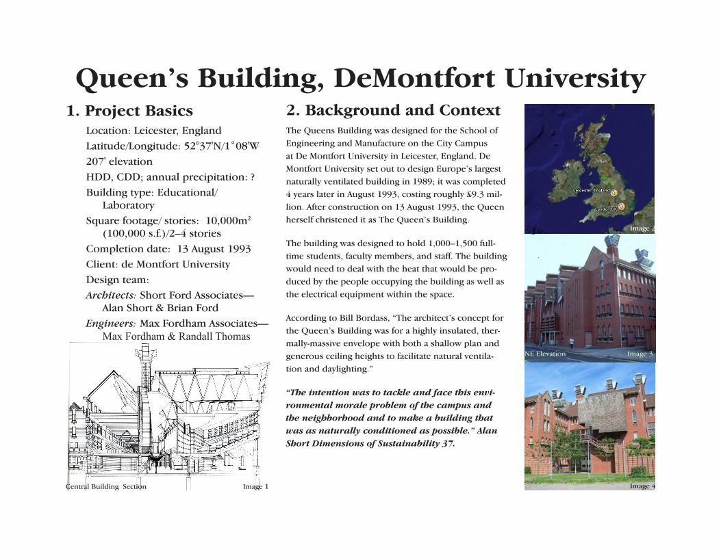
2. Background and ContextThe Queens Building was designed for the School of Engineering and Manufacture on the City Campus at De Montfort University in Leicester, England. De Montfort University set out to design Europe’s largest naturally ventilated building in 1989; it was completed 4 years later in August 1993, costing roughly £9.3 mil-lion. After construction on 13 August 1993, the Queen herself christened it as The Queen’s Building.
The building was designed to hold 1,000–1,500 full-time students, faculty members, and staff. The building would need to deal with the heat that would be pro-duced by the people occupying the building as well as the electrical equipment within the space.
According to Bill Bordass, “The architect’s concept for the Queen’s Building was for a highly insulated, ther-mally-massive envelope with both a shallow plan and generous ceiling heights to facilitate natural ventila-tion and daylighting.”
“The intention was to tackle and face this envi-ronmental morale problem of the campus and the neighborhood and to make a building that was as naturally conditioned as possible.” Alan Short Dimensions of Sustainability 37.
Central Building Section Image 1
Image 2
NE Elevation Image 3
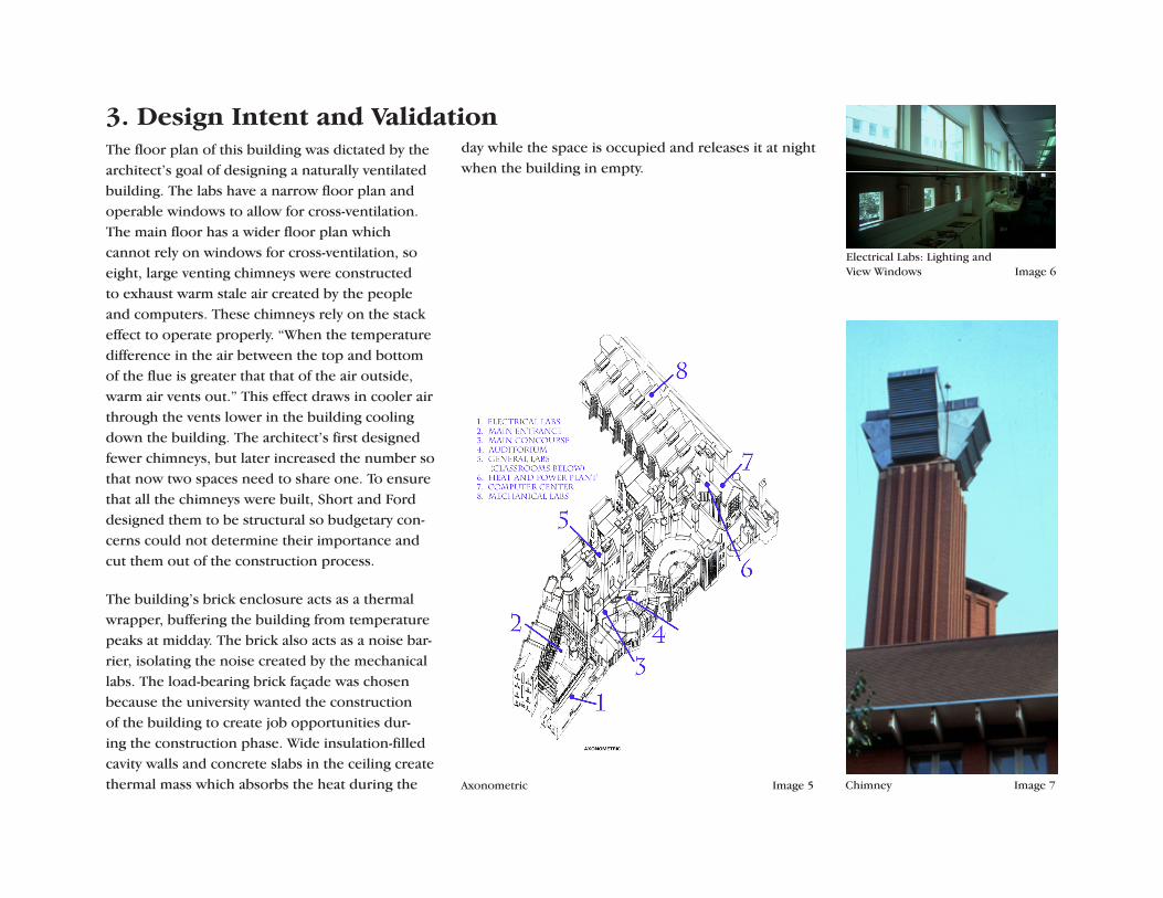
3. Design Intent and ValidationThe floor plan of this building was dictated by the architect’s goal of designing a naturally ventilated building. The labs have a narrow floor plan and operable windows to allow for cross-ventilation. The main floor has a wider floor plan which cannot rely on windows for cross-ventilation, so eight, large venting chimneys were constructed to exhaust warm stale air created by the people and computers. These chimneys rely on the stack effect to operate properly. “When the temperature difference in the air between the top and bottom of the flue is greater that that of the air outside, warm air vents out.” This effect draws in cooler air through the vents lower in the building cooling down the building. The architect’s first designed fewer chimneys, but later increased the number so that now two spaces need to share one. To ensure that all the chimneys were built, Short and Ford designed them to be structural so budgetary con-cerns could not determine their importance and cut them out of the construction process.
The building’s brick enclosure acts as a thermal wrapper, buffering the building from temperature peaks at midday. The brick also acts as a noise bar-rier, isolating the noise created by the mechanical labs. The load-bearing brick façade was chosen because the university wanted the construction of the building to create job opportunities dur-ing the construction phase. Wide insulation-filled cavity walls and concrete slabs in the ceiling create thermal mass which absorbs the heat during the Chimney Image 7
Electrical Labs: Lighting and View Windows Image 6
day while the space is occupied and releases it at night when the building in empty.
Axonometric Image 5
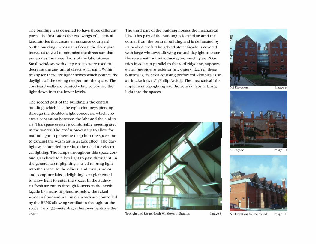
The building was designed to have three different parts. The first one is the two wings of electrical laboratories that create an entrance courtyard. As the building increases in floors, the floor plan increases as well to minimize the direct sun that penetrates the three floors of the laboratories. Small windows with deep reveals were used to decrease the amount of direct solar gain. Within this space there are light shelves which bounce the daylight off the ceiling deeper into the space. The courtyard walls are painted white to bounce the light down into the lower levels.
The second part of the building is the central building, which has the eight chimneys piercing through the double-height concourse which cre-ates a separation between the labs and the audito-ria. This space creates a comfortable meeting area in the winter. The roof is broken up to allow for natural light to penetrate deep into the space and to exhaust the warm air in a stack effect. The day-light was intended to reduce the need for electri-cal lighting. The ramps throughout this space con-tain glass brick to allow light to pass through it. In the general lab toplighting is used to bring light into the space. In the offices, auditoria, studios, and computer labs sidelighting is implemented to allow light to enter the space. In the audito-ria fresh air enters through louvers in the north façade by means of plenums below the raked wooden floor and wall inlets which are controlled by the BEMS allowing ventilation throughout the space. Two 133-meter-high chimneys ventilate the space.
NE Elevation Image 9
SE Façade Image 10
NE Elevation to Courtyard Image 11
The third part of the building houses the mechanical labs. This part of the building is located around the corner from the central building and is delineated by its peaked roofs. The gabled street façade is covered with large windows allowing natural daylight to enter the space without introducing too much glare. “Gan-tries inside run parallel to the roof ridgeline, support-ed on one side by exterior brick piers. Each of these buttresses, its brick coursing perforated, doubles as an air intake louver.” (Philip Arcidi). The mechanical labs implement toplighting like the general labs to bring light into the spaces.
Toplight and Large North Windows in Studios Image 8
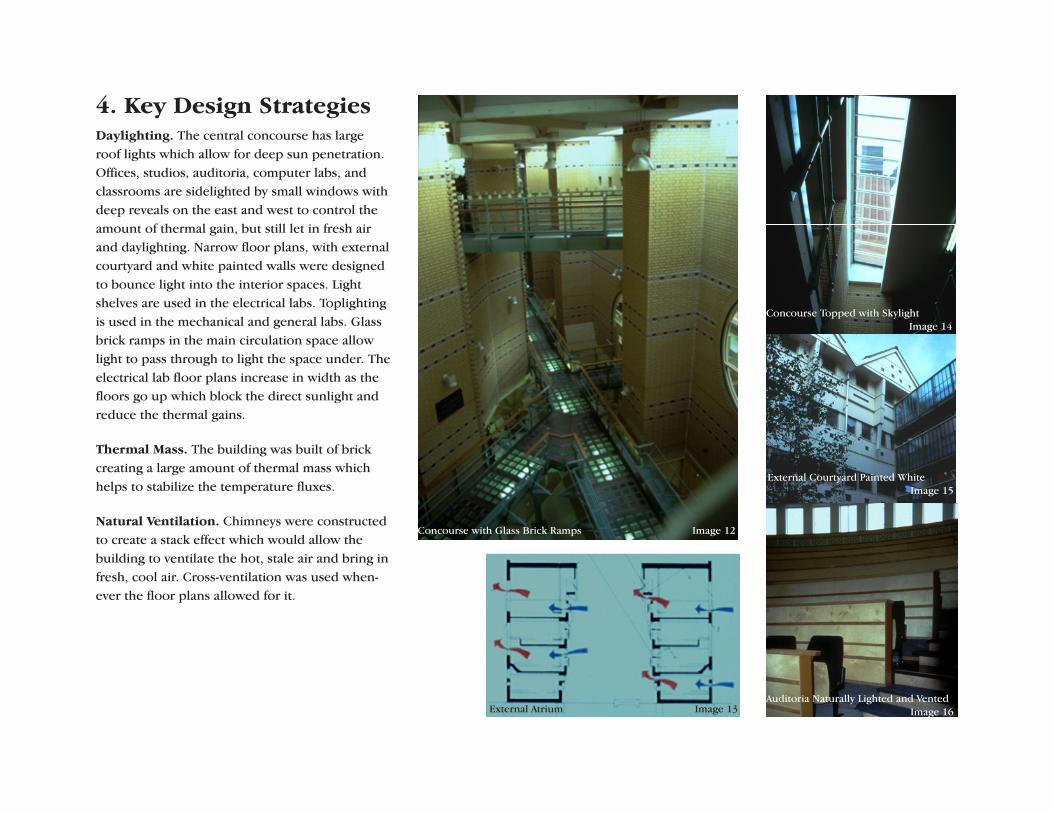
4. Key Design StrategiesDaylighting. The central concourse has large roof lights which allow for deep sun penetration. Offices, studios, auditoria, computer labs, and classrooms are sidelighted by small windows with deep reveals on the east and west to control the amount of thermal gain, but still let in fresh air and daylighting. Narrow floor plans, with external courtyard and white painted walls were designed to bounce light into the interior spaces. Light shelves are used in the electrical labs. Toplighting is used in the mechanical and general labs. Glass brick ramps in the main circulation space allow light to pass through to light the space under. The electrical lab floor plans increase in width as the floors go up which block the direct sunlight and reduce the thermal gains.
Thermal Mass. The building was built of brick creating a large amount of thermal mass which helps to stabilize the temperature fluxes.
Natural Ventilation. Chimneys were constructed to create a stack effect which would allow the building to ventilate the hot, stale air and bring in fresh, cool air. Cross-ventilation was used when-ever the floor plans allowed for it.
Concourse Topped with Skylight Image 14
Concourse with Glass Brick Ramps Image 12
External Atrium Image 13
External Courtyard Painted White Image 15
Auditoria Naturally Lighted and Vented Image 16
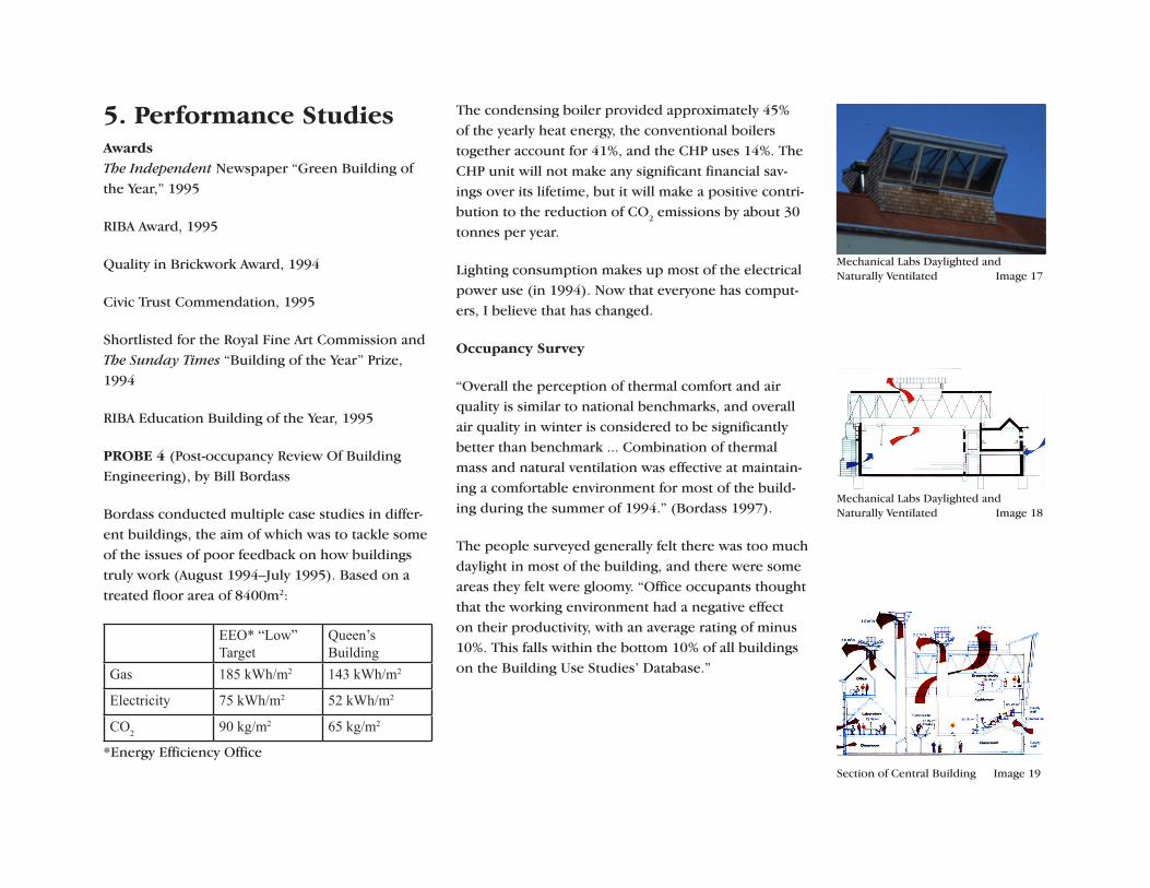
Mechanical Labs Daylighted and Naturally Ventilated Image 17
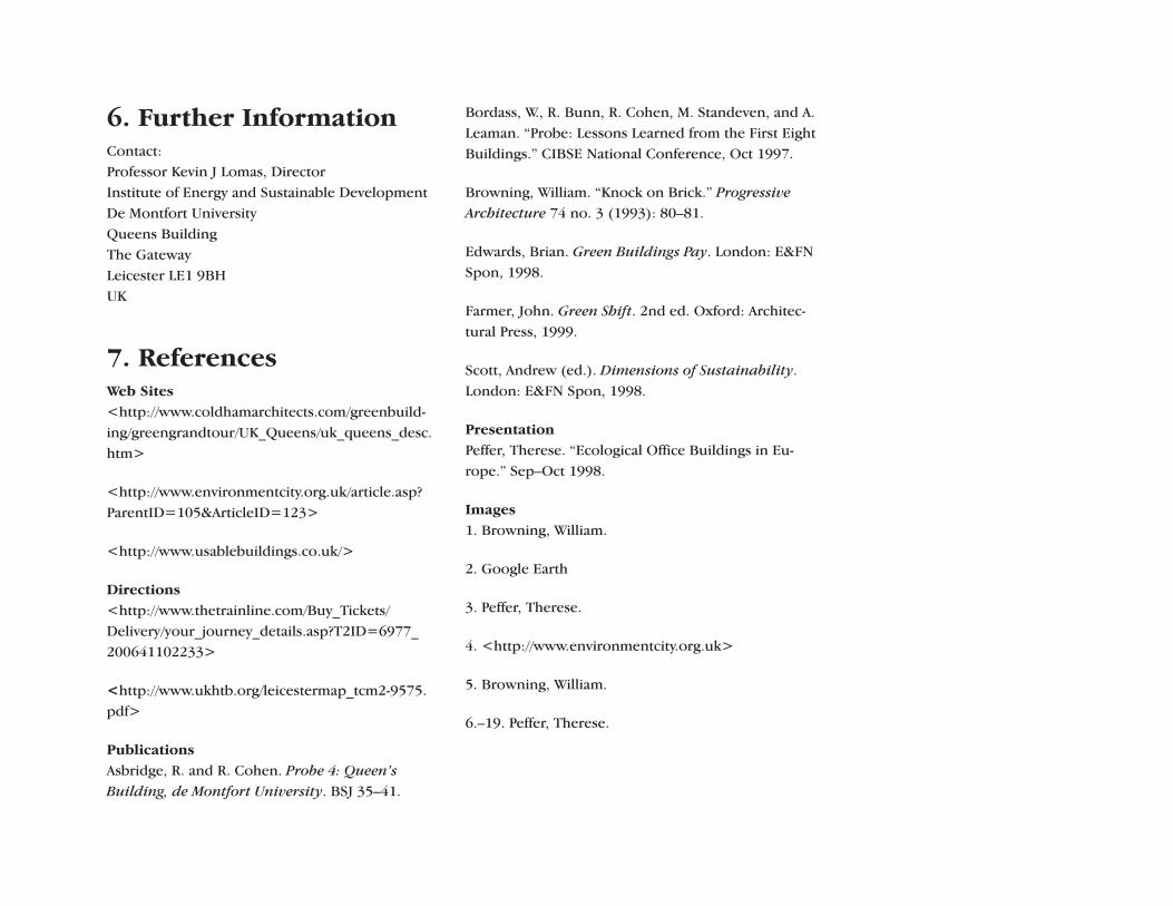
Mechanical Labs Daylighted and Naturally Ventilated Image 18
5. Performance StudiesAwards The Independent Newspaper “Green Building of the Year,” 1995
RIBA Award, 1995
Quality in Brickwork Award, 1994
Civic Trust Commendation, 1995
Shortlisted for the Royal Fine Art Commission and The Sunday Times “Building of the Year” Prize, 1994
RIBA Education Building of the Year, 1995
PROBE 4 (Post-occupancy Review Of Building Engineering), by Bill Bordass
Bordass conducted multiple case studies in differ-ent buildings, the aim of which was to tackle some of the issues of poor feedback on how buildings truly work (August 1994–July 1995). Based on a treated floor area of 8400m2:
EEO* “Low” Target
Queen’s Building
Gas 185 kWh/m2 143 kWh/m2
Electricity 75 kWh/m2 52 kWh/m2
CO2 90 kg/m2 65 kg/m2
*Energy Efficiency Office
The condensing boiler provided approximately 45% of the yearly heat energy, the conventional boilers together account for 41%, and the CHP uses 14%. The CHP unit will not make any significant financial sav-ings over its lifetime, but it will make a positive contri-bution to the reduction of CO2 emissions by about 30 tonnes per year.
Lighting consumption makes up most of the electrical power use (in 1994). Now that everyone has comput-ers, I believe that has changed.
Occupancy Survey
“Overall the perception of thermal comfort and air quality is similar to national benchmarks, and overall air quality in winter is considered to be significantly better than benchmark ... Combination of thermal mass and natural ventilation was effective at maintain-ing a comfortable environment for most of the build-ing during the summer of 1994.” (Bordass 1997).
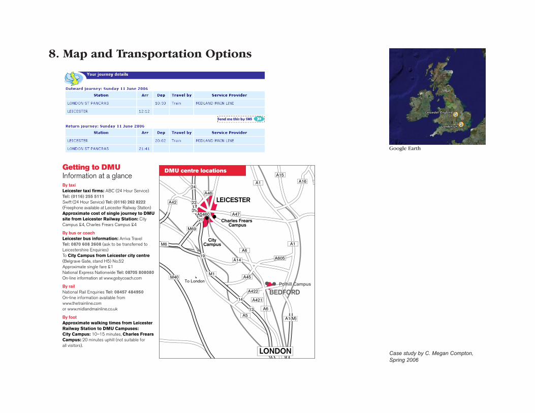
The people surveyed generally felt there was too much daylight in most of the building, and there were some areas they felt were gloomy. “Office occupants thought that the working environment had a negative effect on their productivity, with an average rating of minus 10%. This falls within the bottom 10% of all buildings on the Building Use Studies’ Database.”
Section of Central Building Image 19
6. Further InformationContact: Professor Kevin J Lomas, Director Institute of Energy and Sustainable Development De Montfort University Queens Building The Gateway Leicester LE1 9BH UK
7. ReferencesWeb Sites <http://www.coldhamarchitects.com/greenbuild-ing/greengrandtour/UK_Queens/uk_queens_desc.htm>
<http://www.environmentcity.org.uk/article.asp? ParentID=105&ArticleID=123>
<http://www.usablebuildings.co.uk/>
Directions
<http://www.thetrainline.com/Buy_Tickets/ Delivery/your_journey_details.asp?T2ID=6977_200641102233>
<http://www.ukhtb.org/leicestermap_tcm2-9575.pdf>
Publications
Asbridge, R. and R. Cohen. Probe 4: Queen’s Building, de Montfort University. BSJ 35–41.
Bordass, W., R. Bunn, R. Cohen, M. Standeven, and A. Leaman. “Probe: Lessons Learned from the First Eight Buildings.” CIBSE National Conference, Oct 1997.
Browning, William. “Knock on Brick.” Progressive Architecture 74 no. 3 (1993): 80–81.
Edwards, Brian. Green Buildings Pay. London: E&FN Spon, 1998.
Farmer, John. Green Shift. 2nd ed. Oxford: Architec-tural Press, 1999.
Scott, Andrew (ed.). Dimensions of Sustainability. London: E&FN Spon, 1998.
Presentation Peffer, Therese. “Ecological Office Buildings in Eu-rope.” Sep–Oct 1998.
Images
1. Browning, William.
2. Google Earth
3. Peffer, Therese.
4. <http://www.environmentcity.org.uk>
5. Browning, William.
6.–19. Peffer, Therese.
8. Map and Transportation Options
LEICESTER
MiltonKeynes
erby
Coventry
Pe
BEDFORD
LONDON
A1
M69
A6
A1
A6
A1(M)
M40
M6
A5
M1
A422
2
A42
A47
A16 A
A5460
A14
A45
A605
21
22
21a
24
14
19
A15
A421
To London
13
A46
Charles Frears Campus
CityCampus
LansdowneCampus
Polhill Campus
DMU centre locations
By car from Junction 21 of the M1, or the Leicester end junctionof the M69, take the A5460 to Leicester city centre. Follow thisroad for approximately 4 miles. Go straight through several sets oftraffic lights, and after passing under a railway bridge turn rightinto Upperton Road, following signs to the universities and theRoyal Infirmary. Go over the bridge, then turn left immediately beforecrossing the river into Western Boulevard. For Queens Building,Eric Wood, James Went and the Loading Bay (Goods Reception)take the first right into Mill Lane. For Trinity House, PortlandBuilding, Hawthorn Building and Bosworth House take thesecond right into The Newarke.
From the north leave the M1 at Junction 22 and follow the A50to Leicester (8 miles). When you reach the city centre turn rightinto Vaughan Way (A5460).
Keep in right-hand lane through underpass. After 200 metres,follow road to the left into Newarke Street and keeping in theright-hand lane, turn right into Welford Road (A50). At second setof traffic lights turn right into Carlton Street. Almost
immediately turn right again into Oxford Street, moving into left-hand lane. Take next left into Bonners Lane, continuing into Mill Lane.
From the east take the A46 or A47 to Leicester and follow signs for the city centre.
Please note there is no visitor car park at De MontfortUniversity’s City Campus. Please use the public car parks shownon the maps.
By train/bus If you are arriving by train or bus, the City Campusis situated very near the city centre and is about a 20 minute walkfrom both the bus station and the train station.
Address:City Campus, De Montfort UniversityThe Gateway, Leicester LE1 9BHTel: (0116) 255 1551Fax: (0116) 255 0307
To City Campus
Getting to DMUInformation at a glanceBy taxiLeicester taxi firms: ABC (24 Hour Service) Tel: (0116) 255 5111Swift (24 Hour Service) Tel: (0116) 262 8222(Freephone available at Leicester Railway Station)Approximate cost of single journey to DMUsite from Leicester Railway Station: CityCampus £4, Charles Frears Campus £4
By bus or coachLeicester bus information: Arriva Travel Tel: 0870 608 2608 (ask to be transferred toLeicestershire Enquiries)To City Campus from Leicester city centre(Belgrave Gate, stand H5) No.52Approximate single fare £1National Express Nationwide Tel: 08705 808080On-line information at www.gobycoach.com
By railNational Rail Enquiries Tel: 08457 484950On-line information available fromwww.thetrainline.com or www.midlandmainline.co.uk
By footApproximate walking times from LeicesterRailway Station to DMU Campuses:City Campus: 10–15 minutes, Charles FrearsCampus: 20 minutes uphill (not suitable for all visitors).
De Montfort University City Campus and Charles Frears Campus
Google Earth
Case study by C. Megan Compton,Spring 2006