Embed Size (px)
Citation preview

User Manual (EN/ITA/FRA/ESP/DEU)
QUATTRO
Professional 4-Channel Club Mixer with dual Audio interface for Serato DJ
3
2
1 MASTER
B
AMIC1 4
QUATTRO
FILTERNOISE
CRUSH
MASTER
TAP
FX ON
ECHO
www.mixars.com

EN 1
Safety Instructions
1. Read these Instructions. 2. Keep these Instructions. 3. Heed all Warnings. 4. Follow all Instructions. 5. Do not use this apparatus near water. 6. Clean only with dry cloth. 7. Do not block any ventilation openings. Install in accordance with the manufacturer’s instructions. 8. Do not install near any heat sources such as radiators, heat registers, stoves, or other apparatus (including amplifiers) that produce heat. 9. Do not defeat the safety purpose of the polarized plug. A polarized plug has two blades with one winder than the other. The wide blade is provided for your safety. If the provided plug does not fit into your outlet, consult an electrician for replacement of the obsolete outlet. 10. Protect the power cord from being walked on or pinched particularly at plugs, convenience receptacles, and the point where they exit from the apparatus. 11. Only use attachments/accessories specified by the manufacturer. 12. Use only with the cart, stand, tripod, bracket, or table specified by the manufacturer,or sold with the apparatus. When a cart is used, use caution when moving the cart/apparatus combination to avoid injury from tip-over. 13. Unplug this apparatus during lightning storms or when unused for long periods of time. 14. Refer all servicing to qualified service personnel. Servicing is required when the apparatus has been damaged in any way, such as power-supply cord or plug is damaged, liquid has been spilled or objects have fallen into the apparatus, the apparatus has been exposed to rain or moisture, does not operate normally, or has been dropped. 15. WARNING: To reduce the risk of fire or electric shock, do not expose this apparatus to rain or moisture. 16. Since the appliance coupler is used as the disconnection device, the disconnect device shall remain readily operable. 17. The ventilation should not be impeded by covering the ventilation openings with items, such as newspapers, table-cloths, curtains, etc. 18. No naked flame sources, such as lighted candles, should be placed on the apparatus. 19. The apparatus should be used in moderate climate. 20. The apparatus shall not be exposed to dripping or splashing and that no objects filled with liquids, such as vases, shall be placed on the apparatus.
The exclamation point within the equilateral triangle is intended to alert the user to the presence of important operation and maintenance (servicing) instructions in the literature accompanying this appliance.
The lightning flash with arrowhead symbol within the equilateral triangle is intended to alert the use to the presence of un-insulated “dangerous voltage” within the product’s enclosure that may be of sufficient magnitude to constitute a risk of electric shock.
WARNING To reduce the risk of fire or electric shock, do not expose this apparatus to rain or moisture. The apparatus shall not be exposed to dripping or splashing and that no objects filled with liquids, such as vases, shall be placed on the apparatus.
CAUTION To prevent electric shock, do not use this polarized plug with an extension cord, receptacle or other outlet unless the blades can be fully inserted to prevent blade exposure.
CAUTION To reduce the risk of electric shock, do not remove any cover. No user-serviceable parts inside. Refer servicing to qualified service personnel only.

A. Accessories and Driver Installation
Check for the following parts included in the package with the main unit:
Hardware guide x 1 USB Cable x 1 AC cord x 1
Driver installation
Mac
No driver needed
Windows
Download the driver via our website: www.mixars.com
Double click on the .exe file to start installation and follow the on-screen instructions.
Please note that you may have to reconnect Quattro after installation.
The Mixars Quattro is a class-compliant device for Mac OS X however will require drivers for Windows. Please make sure you have completed driver installation before use with Serato DJ.
EN 2

B. Controls and functions Rear
1. Power On/Off switch Turns the power of the unit On and Off. 2. AC In Connect the power cord here. 3. FX Return input, TRS FX Return input for onboard FX. 4. FX Send output, TRS FX Send output for the onboard FX. 5. Output Level Trim knob Adjust the output level from 0dB to -6dB. 6. Secondary Master output, RCA Secondary RCA Master output (Unbal.), controlled via the «Master» knob 7. Record output Additional RCA Record output (Unbal.) 8. Secondary Line inputs Line signal dedicated secondary input for each channel. 9. Main Phono/Line inputs (Serato Inputs) Main Phono / Line Inputs for each channel. Use the dedicated «Phono / Line» button nearby for selecting the right setting depending on the equipment used (Phono or Line sources). Use this inputs for Serato timecode Vinyls/ CDs in order to use with Serato DJ. 10. Master output, Balanced XLR Main Balanced XLR output, controlled via the «Master» knob 11. Secondary Mic input TRS Microphone input, controlled via the «MIC/AUX» knob. 12. Booth Output, TRS Secondary TRS output (Bal.), controlled via the «Booth» knob 13. Mic input XLR / TRS Combo Microphone input, controlled via the «MIC/AUX» knob
EN 3

Top
14. Mic Talkover/ On/ Off switch Switch the Mic 1 to Talkover, On or off mode. 15. Deck select lever switch Select the destination deck [Deck 3/1 and Deck 2/4] for the corresponding MIDI control area [Left/ Right]. 16. Loop / Loop roll Control the loop and loop roll function in Serato DJ by turning and pressing the knob. Press and hold the «SHIFT» button (see 22) for controlling the loop roll function. 17. Library, Load controls Library: Scroll the Library by turning the knob and display the next level or load the selected song by pressing it. Hold «Shift» and press for turning to the previous level. 18. Sampler Button Switch the performance pads to Sampler Mode. Hold «Shift» and press to switch to User Mode. 19. CUES Button Switch the performance pads to CUES Mode. Hold «Shift» and press to switch to Transport Mode. 20. Performance Pads Use to trigger cue points, samples, transport control or other user defined functions in Serato DJ.
EN 4

21. Sync Button Syncronize a track to another by pressing the corresponding «Sync» button and turn off the function by pressing «Sync» while holding «Shift». 22. Shift button Hold for enabling the shifted functions of some controls 23. Crossfader Fader Curve switch Switch among the 3 cross fader settings Hard (towards left) to Soft (towards right) for different application. 24. Split Cue On/Off switch If enabled, the headphones signal gets split: Master signal on one channel, and the enabled Cue signals selected via the «CUE» buttons (see 43), on the other channel. 25. Crossfader Reverse switch Reverses the Left with the Right Channel on the crossfader. 26. CUE Mix Turn for adjusting between Cue and Master signal on the headphone output. 27. Upfader Fader Curve switch Switch among the 3 cross fader settings Hard (towards left) to Soft (towards right) for different application. 28. Headphones Level Adjust the headphones volume. 29. Headphones Output connector 6.35mm and 3.5mm jack for connecting headphones 30. Master On CUE switch Press to enable the Master on CUE headphone channel. 31. Sampler Volume Control sampler volume level in Serato DJ 32. Crossfader Crossfade between the Left and Right channels of audio assigned to them by the « Channel assignment switch» (see 41) 33. FX ON switch Enable/ disable the FX proceeded signal to the master output. 34. TAP button Tap to enter manual BPM to the FX unit. Press and hold for 3 sec to enable auto BPM detection. 35. FX CUE switch Enable/ disable the FX proceeded signal to the headphone cue output. 36. FX Depth parameter knob Adjust the FX depth or dry/wet of the selected FX. 37. FX Select encoder Turn to select different FX and press to select. 38. FX Time parameter knob Adjust the FX time/ beat parameter of the selected FX. Press to switch between Time and Beat parameter. 39. FX on Channel selector Select the desired channel to apply the FX. 40. Onboard FX display Display various information about the FX 41. Channel assignment switch Assign the corresponding channel to the left or right channel of the corssfader. When “THRU” is selected, the channel signal will go through to master directly bypassing the crossfader. 42. Channel faders Adjust the volume level of the corresponding channel. 43. Cue On/Off Assign the corresponding channel to the Cue signal. 44. Channel Sound Texture FX knob (FILTER) Adjust the parameter/ level of the selected sound texture FX. 45. Channel level meter Display the corresponding channel level signal 46. Channel EQ Adjust the equalizer settings for the corresponding channel 47. Channel Trim Adjust the overall level for the corresponding channel. 48. Source Switch Select the input to be controlled on the corresponding channel. Switch between Phono/Line (see 9), Line (see 8), Serato – USB1 (see 50) or Serato – USB2 (see 49). For Deck 4, there is an extra input source of MIC 2. 49. USB 2 connector Connect the mixer to your computer using the included USB cable for using it with Serato DJ. To use this USB device, use the «Source Switch» (see 48) to select to USB2 50. USB 1 connector
EN 5
Connect the mixer to your computer using the included USB cable for using it with Serato DJ. To use this USB device, use the «Source Switch» (see 48) to select to USB1 51. Master volume Adjust the volume of the master level signal. 52. Master Level Meter Display the Master Level Signal. 53. Booth Adjust the level of the «Booth» output. 54. Sound Texture FX selection switch. Switch between Filter, Noise, Crush and Echo effect and control the FX parameter by «Channel Sound Texture FX knob» (see 44) 55. Mic 1 tone control Control the tone of the mic 1. 56. Mic 1 level control Control the level of the mic 1.
C. On board FX Controls and functions The Quattro provides a BPM synced FX unit for adding special effects to the performance. There are 15 different FX selections: Filter Flanger Delay Echo Reverb Transformer Pitch Loop Roll Reverse Roll Noise Bit Crusher Gate Tape Delay Vinyl Brake Send/return
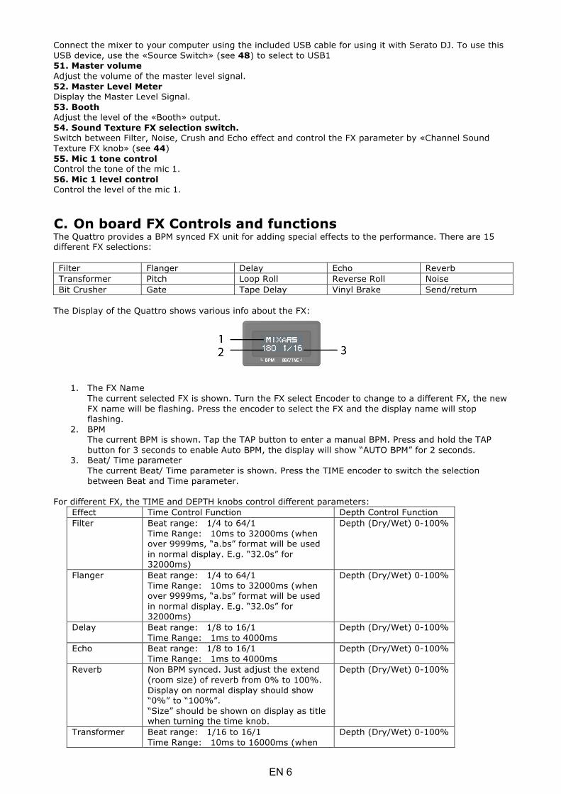
The Display of the Quattro shows various info about the FX:
1. The FX Name The current selected FX is shown. Turn the FX select Encoder to change to a different FX, the new FX name will be flashing. Press the encoder to select the FX and the display name will stop flashing.
2. BPM The current BPM is shown. Tap the TAP button to enter a manual BPM. Press and hold the TAP button for 3 seconds to enable Auto BPM, the display will show “AUTO BPM” for 2 seconds.
3. Beat/ Time parameter The current Beat/ Time parameter is shown. Press the TIME encoder to switch the selection between Beat and Time parameter.
For different FX, the TIME and DEPTH knobs control different parameters:
Effect Time Control Function Depth Control Function Filter Beat range: 1/4 to 64/1
Time Range: 10ms to 32000ms (when over 9999ms, “a.bs” format will be used in normal display. E.g. “32.0s” for 32000ms)
Depth (Dry/Wet) 0-100%
Flanger Beat range: 1/4 to 64/1 Time Range: 10ms to 32000ms (when over 9999ms, “a.bs” format will be used in normal display. E.g. “32.0s” for 32000ms)
Depth (Dry/Wet) 0-100%
Delay Beat range: 1/8 to 16/1 Time Range: 1ms to 4000ms
Depth (Dry/Wet) 0-100%
Echo Beat range: 1/8 to 16/1 Time Range: 1ms to 4000ms
Depth (Dry/Wet) 0-100%
Reverb Non BPM synced. Just adjust the extend (room size) of reverb from 0% to 100%. Display on normal display should show “0%” to “100%”. “Size” should be shown on display as title when turning the time knob.
Depth (Dry/Wet) 0-100%
Transformer Beat range: 1/16 to 16/1 Time Range: 10ms to 16000ms (when
Depth (Dry/Wet) 0-100%
EN 6

over 9999ms, “a.bs” format will be used in normal display. E.g. “16.0s” for 16000ms)
Pitch Non BPM synced. Pitch range from -50% to 100%. “PITCH” is shown as title when adjusting this parameter.
Fixed 100% Wet
Loop Roll Beat range: 1/16 to 16/1 Time Range: 10ms to 4000ms
Fixed 100% Wet
Reverse Roll Beat range: 1/16 to 16/1 Time Range: 10ms to 4000ms
Fixed 100% Wet
Noise Beat range: 1/4 to 64/1 Time Range: 10ms to 32000ms (when over 9999ms, “a.bs” format will be used in normal display. E.g. “32.0s” for 32000ms)
Depth (Dry/Wet) 0-100%
Bit Crusher Non BPM synced. Quality parameter range from -100% to 100%. “QUALITY” is shown on title when adjusting this parameter
Depth (Dry/Wet) 0-100%
Gate Non BPM synced. Threshold adjustment of steps: From 0% to 100%
Depth (Dry/Wet) 0-100%
Tape Delay Non BPM synced. Tone pitch of the delay signal form -100% to 100%.
Depth (Dry/Wet) 0-100%
Vinyl Brake Non BPM synced. Break time from 10ms to 4000ms.
Manual control of the Break FX. Turn clockwise to engage and shorten the break time. Turn anti-clockwise to re-engage the break FX with a longer break time.
Send/return NA. Display “---“ for the time/ beat field Depth (Dry/Wet) 0-100%
EN 7

D. Audio Routing There are 2 audio routing settings in Quattro, namely the Serato routing and non-Serato routing. In Serato mode routing, the Quattro acts as a controller and most of the mixing is done in Serato DJ software. It allows post-crossfader FX from Serato DJ. The Serato mode audio routing:
EN 8

In non-Serato mode routing, the Quattro works as a typical external hardware mixer that the mixing is done by Quattro hardware. The non-Serato mode Audio routing:
There are different ways to switch between the 2 audio routings:
1. When Serato DJ software is open and initiated, it will trigger the connected Quattro to change to Serato mode routing automatically.
2. Press and hold the MASTER button and power on the Quattro. Audio routing mode and be selected and changed by using the FX Select encoder and the current selected mode is shown on the Display. Turn the FX Select encoder to select desired audio routing and press to confirm and finish the power on.
3. When the Quattro is powered on and in use, press and hold the 2 SHIFT buttons for 5 seconds, a system utility menu will be shown on the display. Use the FX Selector Encoder to select to the Audio routing section and select desired audio routing.
The audio interface is a 10-in 12-out interface with assignment: CH Inputs Outputs 1 Deck 1 in L (DVS) Deck 1 out L 2 Deck 1 in R (DVS) Deck 1 out R 3 Deck 2 in L (DVS) Deck 2 out L 4 Deck 2 in R (DVS) Deck 2 out R 5 Deck 3 in L (DVS) Deck 3 out L 6 Deck 3 in R (DVS) Deck 3 out R 7 Deck 4 in L (DVS) Deck 4 out L 8 Deck 4 in R (DVS) Deck 4 out R 9 Record in L CUE out L 10 Record in R CUE out R 11 NA Sampler out L 12 NA Sampler out R 13 NA NA 14 NA NA 15 NA NA 16 NA NA
EN 9
E. System Utility Menu To enter System Utility Menu, press and hold the 2 SHIFT buttons when the Quattro is working. The menu will be shown on the Display. Use the FX Select Encoder to browse to different option and press the encoder to select and change the settings: 1. Audio routing Select between Serato and non-Serato Audio routing 2. Crossfader power Select between the linear and power crossfader setting. This will also update the selection in connected Serato DJ software on both USB 1 and USB 2 connection. 3. Firmware Version Display the firmware version. 4.Exit system utility menu Press the FX Select Encoder to exit system utility menu.
F. Firmware Update
Mixars will continue improve the product and fix bugs by releasing new firmware for the production. New firmware and firmware update software tool can be downloaded from Mixars website (http://www.mixars.com). Firmware update procedure: 1. Download the firmware update tool and latest firmware from Mixars website. 2. Connect the USB able to the computer. 3. Press and hold the FX CUE and TAP button and power on. “FIRMWARE UPDATE” will be shown on
the display and the Quattro is in Firmware update mode. 4. Open the firmware update software and locate the firmware update file. 5. Follow the on-screen instruction to start firmware update and wait for the prompt for update
finish 6. Power cycle the Quattro after firmware update.
G. Specifications 1. GENERAL SECTION
Power Supply AC 100~240V 50Hz/60Hz Dimensions 320(W) x 362(D) x 107(H) mm Consumption 20W Weight 5.35Kg
2. STANDARD TEST CONDITION Ambient Temperature 23 +/- 2 degC Relative Humidity 65% +/- 5% NOTE: Measurements can be carried out between 5 degC to 35 degC and 45% to 85% relative humidity.
3. INPUT/OUTPUT IMPEDANCE & SENSITIVITY: (1KHz,EQ FLAT, MAX. GAIN ) 3-1. INPUT IMPEDANCE AND REFERENCE INPUT LEVEL:
LINE: 47KΩ /-14dBV (200mV) PHONO: 47KΩ /-50dBV (3.16mV) MIC : 5KΩ/-54dBV (2mV) RETURN: 47KΩ /-20dBV (100mV) USB -12dBFS
3-2. OUTPUT IMPEDANCE AND REFERENCE OUT LEVEL: MASTER(XLR): 600 OHM / 0dBV (1V) ± 2dB (Signal to Signal 600 ohm) BOOTH: 600 OHM / 0dBV (1V) ± 2dB (Signal to Signal 600 ohm) MASTER(RCA): 1K OHM / 0dBV (1V) ± 1dB (load=100K ohm) RECORD: 1K OHM / -9dBV (355mV) ± 1dB (load=100K ohm) SEND: 1K OHM / -14dBV (200mV) ± 1dB (load=100K ohm) PHONE: 32 OHM / -3dBV (708mV) ± 1dB (load=32 ohm)
EN 10

4. MAXIMUM GAIN: ( EQ FLAT, REFERENCE INPUT LEVEL , MAX. GAIN) MASTER (XLR)�BOOTH OUTPUT: LINE : +14dB (AT 600Ω) ± 1dB PHONO : +50dB (AT 600Ω) ± 2dB MIC : +54dB (AT 600Ω) ± 2dB RETURN: +20dB (AT 600Ω) ± 1dB MASTER(RCA) OUTPUT: LINE : +14dB (AT 100KΩ) ± 1dB PHONO : +50dB (AT 100KΩ) ± 2dB MIC : +54dB (AT 100KΩ) ± 2dB RETURN: +20dB (AT 600Ω) ± 1dB RECORD OUTPUT: LINE : +5dB (AT 100KΩ) ± 1dB PHONO : +41dB (AT 100KΩ) ± 2dB MIC : +45dB (AT 100KΩ) ± 2dB RETURN: +11dB (AT 600Ω) ± 1dB SEND OUTPUT: LINE : +0dB (AT 100KΩ) ± 1dB PHONO : +36dB (AT 100KΩ) ± 2dB MIC : +40dB (AT 100KΩ) ± 2dB
5. MAXIMUM INPUT: ( EQ FLAT,MIC,TRIM,MASTER AT 9 O’CLOCK, ADJUST INPUT 1KHz LEVEL TO OUTPUT LEVEL LESS THAN 1% T.H.D WITH A-w/20KHz LPF ) LINE: MORE THAN +15dBV THD<1% RETURN: MORE THAN +9dBV THD<1% PHONO: MORE THAN -21dBV THD<1% MIC: MORE THAN -25dBV THD<1%
6. MAXIMUM OUTPUT: (LINE INPUT, EQ FLAT,MIC,TRIM,MASTER AT MAX, ADJUST INPUT 1KHz LEVEL TO OUTPUT LEVEL LESS THAN 1% WITH A-w/20kHz LPF) MASTER(XLR): MORE THAN +17dBV LOAD=600Ω THD<1% BOOTH: MORE THAN +17dBV LOAD=600Ω THD<1% MASTER(RCA): MORE THAN +17dBV LOAD=100KΩ THD<1% RECORD: MORE THAN +8 dBV LOAD=100KΩ THD<1% SEND: MORE THAN +3dBV LOAD=100KΩ THD<1% PHONE: MORE THAN +4dBV LOAD=32Ω THD<1%
7. FREQUENCY RESPONSE: (EQ FLAT, PHONO AT -60dB/OTHER REFERENCE INPUT LEVEL , MIC,TRIM,MASTER AT MAX.) LINE: 20 - 20KHz +2/-3dB MIC: 20 - 20KHz +2/-3dB PHONO: 20 - 20KHz +2/-3dB USB: 20 - 20KHz (48K/24b-1KHz�20Hz�20KHz.WAV) +2/-3dB
8. THD + N: (1KHz INPUT ,MIC TRIM & MASTER AT 12 O’CLOCK , WITH A-w./20KHz LPF) LINE� 0.01 % AT 0dB INPUT RETURN� 0.01 % AT 0dB INPUT PHONO� 0.02 % AT -36dB INPUT MIC� 0.03 % AT -40dB INPUT
9. S/N RATIO: ( 1KHz INPUT , MIC/AUX, TRIM, MASTER AT 12 O’CLOCK, WITH A-w/20KHz LPF, INPUT SHORT WHEN NO SIGNAL) LINE� 81dB AT 0dB INPUT RETURN� 81dB AT 0dB INPUT PHONO� 81dB AT -36dB INPUT MIC� 74dB AT -40dB INPUT
10. CROSSTALK: (1KHz INPUT , MIC/AUX, TRIM, MASTER AT 12 O’CLOCK WITH A-w/ 20KHz LPF, INPUT SHORT WHEN NO SIGNAL ) LINE: MORE THAN 81dB @ EACH CHANNEL INPUT AT 0dB INPUT PHONO: MORE THAN 81dB @ EACH CHANNEL INPUT AT -36dB INPUT
11. L&R CHANNEL SEPARATION: (1KHz INPUT , MIC/AUX, TRIM, MASTER AT 12 O’CLOCK WITH A-w/20KHz LPF, INPUT SHORT WHEN NO SIGNAL) LINE: MORE THAN 81dB @BETWEEN L AND R CHANNEL AT 0dB INPUT PHONO: MORE THAN 81dB @BETWEEN L AND R CHANNEL AT -36dB INPUT
EN 11

12. EQUALIZER RESPONSE: (REFERENCE INPUT LEVEL , MIC/AUX, TRIM MASTER AT MAX. WITH 20KHz LPF) LINE: (1) Low Band: (Low Band center frequency is 70Hz )
Maximum level: +12 ± 1dB (at 70Hz) Minimum level: -25 ± 1dB (at 70Hz)
(2) Middle Band: (Middle Band center frequency is 1KHz ) Maximum level: +12 ± 1dB (at 1KHz) Minimum level: -25 ± 1dB (at 1KHz)
(3) High Band: (Hi Band center frequency is 13KHz ) Maximum level: +12 ± 1dB (at 13KHz) Minimum level: -25 ± 1dB (at 13KHz)
MIC� Hi: -28dB ± 2dB AT 100Hz Low: -28dB ± 2dB AT 10KHz
13. Fader Kill: (0dB 1KHz INPUT LEVEL , TRIM/MASTER AT 12 O’CLOCK. MIC SW OFF WITH A-w/ 20KHz LPF ) Channel Fader: MORE THAN 91dB AT 1KHz Cross Fader: MORE THAN 91dB AT 1KHz
14. LEVEL DIFFERENCE L&R: (1KHz REFERENCE INPUT LEVEL , TRIM, MASTER AT MAX. WITH A-w/20KHz LPF) LINE: ±1dB PHONO: ±1.5dB
15. NOTES (1) The specifications are subject to change to any improvement by negotiations in advance. (2) The parts are subject to change to any improvement within the range of the specifications.
EN 12

ITA 1
Istruzioni di sicurezza
1. Leggere queste istruzioni. 2. Conservare queste istruzioni. 3. Prestare attenzione a tutte le avvertenza. 4. Seguire tutte le istruzioni. 5. Non utilizzare quest’apparecchiatura in prossimità di acqua. 6. Pulire solo con un panno asciutto. 7. Non ostruire le aperture di ventilazione. Eseguire l’installazione secondo le istruzioni del costruttore. 8. Non effettuare l’installazione in prossimità di fonti di calore come radiatori, regolatori di calore, stufe o altre apparecchiature (compresi gli amplificatori) che producono calore. 9. Non inibire la funzione di sicurezza della spina polarizzata. La spina polarizzata ha due piedini, uno più largo dell’altro. Il piedino più largo ha una funzione di sicurezza. Qualora la spina fornita non si inserisse nella vostra presa, consultare un tecnico per la sostituzione della presa. 10. Assicurarsi che il cavo di alimentazione non possa essere calpestato o schiacciato, in particolare in prossimità delle spine, delle prese a muro e nei punti in cui esce dall’apparecchio. 11. Utilizzare solamente accessori specificati dal costruttore. 12. Utilizzare solamente con il carrello, il cavalletto, il treppiedi, la staffa o il piano specificati dal costruttore oppure forniti insieme all’apparecchio. Quando si utilizza un carrello, prestare attenzione nella movimentazione del gruppo carrello/apparecchio per evitare lesioni provocate dal ribaltamento del gruppo stesso. 13. Scollegare questo apparecchio in caso di tempeste di fulmini oppure di inutilizzo prolungato. 14. Affidare tutte le operazioni di manutenzione a personale qualificato. Gli interventi di manutenzione sono necessari quando l’apparecchio viene danneggiato in qualunque modo, ad esempio in caso di danni al cavo di alimentazione o alla spina, di fuoriuscita di liquido o di caduta di oggetti all’interno dell’apparecchio stesso, o ancora qualora l’apparecchio, dopo esser stato esposto a pioggia o umidità, non funzioni correttamente o qualora sia caduto. 15. AVVERTENZA: Per ridurre il rischio di incendio o di folgorazione, non esporre l’apparecchiatura alla pioggia o all’umidità. 16. Poiché l’accoppiatore dell’apparecchio viene utilizzato come sezionatore, esso deve essere sempre prontamente azionabile. 17. Non ostacolare la ventilazione coprendo le relative aperture con oggetti, giornali, tovaglie, tende o altro. 18. Evitare di posizionare sull’apparecchiatura fonti di fiamme libere, come ad esempio candele accese. 19. L’apparecchiatura è progettata per essere utilizzata in ambienti con clima temperato. 20. L’apparecchiatura non deve essere esposta a gocciolamento o schizzi e pertanto nessun oggetto contenente liquidi, come ad esempio vasi, dovrà essere posizionato sulla stessa.
Il punto esclamativo all’interno del triangolo ha lo scopo di attirare l’attenzione dell’utente sulla presenza di istruzioni di funzionamento e di manutenzione (assistenza) importanti riportate nella documentazione fornita insieme all’apparecchiatura.
Il simbolo del lampo all’interno del triangolo ha lo scopo di attirare l’attenzione dell’utente sulla presenza di “tensione pericolosa” non isolata nei ripari del prodotto, che potrebbe avere una potenza sufficiente a costituire un rischio di scossa elettrica.
AVVERTENZA Per ridurre il rischio di incendio o di folgorazione, non esporre l’apparecchiatura alla pioggia o all’umidità. L’apparecchiatura non deve essere esposta a gocciolamento o schizzi e pertanto nessun oggetto contenente liquidi, come ad esempio vasi, dovrà essere posizionato sulla stessa.
ATTENZIONE Per prevenire le scosse elettriche non utilizzare questa spina polarizzata con una prolunga, una presa a muro o altre prese a meno che i piedini non possano essere inseriti completamente così da evitare l’esposizione degli stessi.
ATTENZIONE Per ridurre il rischio di scosse elettriche non rimuovere i pannelli di copertura. Non sono presenti all’interno componenti che prevedono una manutenzione da parte dell’utente. Affidare le operazioni di manutenzione solamente a personale qualificato.
ITA 2
A. Accessori e installazione dei driver
Verificare che i componenti riportati di seguito siano contenuti
nell’imballaggio dell’unità principale:
guida hardware x 1 cavo USB x 1 cavo CA x 1
Installazione dei driver
Mac
Non è necessario alcun driver
Windows
Scaricare il driver dal nostro sito: www.mixars.com
Fare doppio click sul file .exe per avviare l’installazione e seguire le istruzioni a video.
Potrebbe essere necessario ricollegare Quattro dopo l’installazione.
Mixars Quattro è un dispositivo compatibile con Mac OS X; tuttavia richiede alcuni driver per Windows. Accertarsi di aver completato l’installazione dei driver prima dell’utilizzo con Serato DJ.

B. Comandi e funzioni Lato posteriore
1. Interruttore di accensione/spegnimento Consente di attivare e disattivare l’alimentazione dell’unità. 2. Ingresso CA Collegare qui il cavo di alimentazione. 3. Ingresso ritorno FX, TRS Ingresso di ritorno FX per l’FX a bordo. 4. Uscita invio FX, TRS Uscita invio FX per l’FX a bordo. 5. Pomello di regolazione livello uscita Regolazione del livello di uscita da 0dB a -6dB. 6. Uscita master secondaria, RCA Uscita master RCA secondaria (sbil.), comandata tramite il pomello «Master» 7. Uscita registrazione Uscita di registrazione RCA supplementare (sbil.) 8. Ingressi linea secondari Ingresso secondario dedicato al segnale di linea per ogni canale. 9. Ingressi phono/linea principali (ingressi Serato) Ingressi phono/linea principali per ogni canale. Utilizzare il pulsante dedicato “phono/linea” a lato per selezionare la corretta impostazione in base all’apparecchiatura utilizzata (fonti phono o di linea). Utilizzare questi ingressi per vinili/CD timecode di Serato per utilizzare Serato DJ. 10. Uscita master, XLR bilanciato Uscita XLR principale bilanciata, comandata tramite il pomello “Master” 11. Ingresso Mic secondario Ingresso microfono TRS, comandato tramite pomello “MIC/AUX”. 12. Uscita cabina, TRS Uscita TRS secondaria (bil.), comandata tramite il pomello “Cabina” 13. Ingresso Mic Ingresso microfono combinato XLR/TRS, comandato tramite pomello “MIC/AUX”
ITA 3
Parte superiore
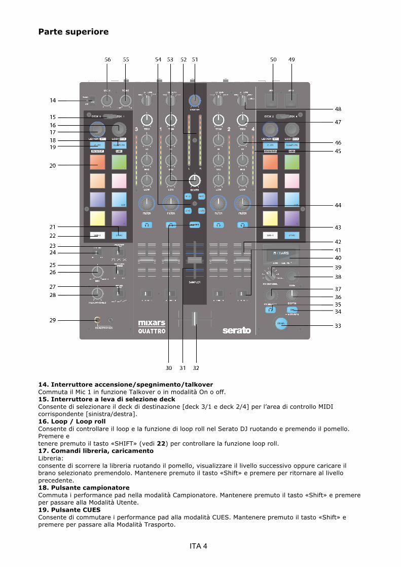
14. Interruttore accensione/spegnimento/talkover Commuta il Mic 1 in funzione Talkover o in modalità On o off. 15. Interruttore a leva di selezione deck Consente di selezionare il deck di destinazione [deck 3/1 e deck 2/4] per l’area di controllo MIDI corrispondente [sinistra/destra]. 16. Loop / Loop roll Consente di controllare il loop e la funzione di loop roll nel Serato DJ ruotando e premendo il pomello. Premere e tenere premuto il tasto «SHIFT» (vedi 22) per controllare la funzione loop roll. 17. Comandi libreria, caricamento Libreria: consente di scorrere la libreria ruotando il pomello, visualizzare il livello successivo oppure caricare il brano selezionato premendolo. Mantenere premuto il tasto «Shift» e premere per ritornare al livello precedente. 18. Pulsante campionatore Commuta i performance pad nella modalità Campionatore. Mantenere premuto il tasto «Shift» e premere per passare alla Modalità Utente. 19. Pulsante CUES Consente di commutare i performance pad alla modalità CUES. Mantenere premuto il tasto «Shift» e premere per passare alla Modalità Trasporto.
ITA 4
20. Performance pad Da utilizzare per attivare punti cue, campioni, comando di trasporto o altre funzioni definite dall’utente in Serato DJ. 21. Pulsante Sync Consente di sincronizzare una traccia con un’altra premendo il rispettivo pulsante”Sync” e di spegnere la funzione premendo “Sync” e mantenendo premuto “Shift”. 22. Tasto Shift Mantenere premuto il tasto Shift per abilitare le funzioni “shiftate” degli stessi comandi 23. Interruttore curva Fader Crossfader Consente di passare da una delle 3 impostazioni di crossfader da Hard (verso sinistra) a Soft (verso destra) disponibili per diverse applicazioni. 24. Interruttore accensione/spegnimento split cue Se abilitato, il segnale delle cuffie viene suddiviso: segnale master su un canale e segnali Cue abilitati tramite i pulsanti “CUE” (vedi 43) sull’altro canale. 25. Interruttore inversione crossfader Consente di invertire il canale sinistro con il destro sul crossfader. 26. CUE Mix Ruotarlo per regolare il segnale Cue e Master sull’uscita delle cuffie. 27. Interruttore curva Fader Upfader Consente di passare da una delle 3 impostazioni di crossfader da Hard (verso sinistra) a Soft (verso destra) disponibili per diverse applicazioni. 28. Livello cuffie Regolare il volume delle cuffie. 29. Connettore uscita cuffie jack da 6,35mm e 3,5mm per il collegamento delle cuffie 30. Interruttore Master su CUE Premerlo per abilitare il Master sul canale CUE delle cuffie. 31. Volume campionatore Consente di controllare il volume del campionatore in Serato DJ 32. Crossfader Crossfade tra i canali audio sinistro e destro ad essi assegnati dall’interruttore di “assegnazione canale” (vedi 41) 33. Interruttore FX ON Consente di abilitare/disabilitare il segnale FX verso l’uscita master. 34. Pulsante TAP Premere questo pulsante per inserire manualmente un valore di BPM nell’unità FX. Premere e mantenere premuto per 3 secondi per abilitare il rilevamento automatico del BPM. 35. Interruttore FX CUE Consente di abilitare/disabilitare il segnale FX verso l’uscita cue delle cuffie. 36. Pomello parametro profondità FX Consente di regolare la profondità FX o dry/wet dell’FX selezionato. 37. Encoder selezione FX Ruotarlo per selezionare un FX diverso e premere per selezionarlo. 38. Pomello parametro tempo FX Consente di regolare il parametro di beat/tempo dell’FX selezionato. Premerlo per passare dal parametro Tempo al parametro Beat. 39. Selettore canale FX Consente di selezionare il canale desiderato da applicare all’FX. 40. Display FX di bordo Visualizza varie informazioni sull’FX 41. Interruttore di assegnazione canale Consente di assegnare il canale corrispondente al canale sinistro o destro del crossfader. Quando si seleziona “THRU”, il segnale del canale passerà attraverso il master bypassando direttamente il crossfader. 42. Fader canali Consente di regolare il livello del volume del canale corrispondente. 43. Cue On/Off Consente di assegnare il canale corrispondente al segnale Cue. 44. Pomello FX texture del suono del canale (FILTRO) Consente di regolare il parametro/livello dell’FX texture suono selezionata. 45. Misuratore livello canale Visualizza il segnale del livello del canale corrispondente 46. Equalizzatore canale Consente di regolare le impostazioni dell'equalizzatore per il canale corrispondente 47. Regolazione canale Consente di regolare il livello generale del canale corrispondente. 48. Interruttore fonte Consente di selezionare l’ingresso da controllare sul canale corrispondente. Consente di passare da Phono/linea (vedi 9), linea (vedi 8), Serato – USB1 (vedi 50) o Serato – USB2
ITA 5

(vedi 49). Per il deck 4 è presente una fonte ingresso supplementare del MIC 2. 49. Connettore USB 2 Consente di collegare il mixer al vostro computer utilizzando il cavo USB fornito in dotazione per utilizzare il mixer con Serato DJ. Per utilizzare questo dispositivo USB, agire sull’interruttore “Fonte” (vedi 48) per selezionare l’USB2 50. Connettore USB 1 Consente di collegare il mixer al vostro computer utilizzando il cavo USB fornito in dotazione per utilizzare il mixer con Serato DJ. Per utilizzare questo dispositivo USB, agire sull’interruttore “Fonte” (vedi 48) per selezionare l’USB1 51. Volume master Regolare il volume del segnale di livello master. 52. Misuratore livello master Visualizza il segnale del livello master. 53. Cabina Consente di regolare il livello dell’uscita “Cabina”. 54. Interruttore di selezione FX texture del suono. Consente di impostare filtro, disturbo, effetto Crush ed Eco e di controllare il parametro FX tramite il pomello “FX texture del suono del canale” (vedi 44) 55. Comando tono Mic 1 Consente di controllare il tono del microfono 1. 56. Comando livello Mic 1 Consente di controllare il livello del microfono 1.
C. Comandi e funzioni FX di bordo Quattro fornisce BPM sincronizzati all’unità FX per l’aggiunta di effetti speciali alla prestazione. Sono disponibili 15 diverse selezioni di FX: Filter (Filtro) Flanger Delay (Ritardo) Echo (Eco) Reverb (Riverbero) Transformer (Trasformatore)
Pitch (Altezza) Loop Roll Reverse Roll Noise (Disturbo)
Bit Crusher Gate Tape Delay (Ritardo nastro)
Vinyl Break (Effetto Vinyl Break)
Send/return (Invio/ritorno)
Il display di Quattro mostra diverse informazioni sull’FX:
1. il nome dell’FX l’FX selezionato attualmente. Ruotare l’encoder di selezione FX per passare a un FX diverso; il nome del nuovo FX inizierà a lampeggiare. Premere l’encoder per selezionare l’FX; il nome visualizzato cesserà di lampeggiare.
2. BPM Viene visualizzato il BPM corrente. Toccare il pulsante TAP per inserire manualmente un valore di BPM. Premere e tenere premuto il pulsante TAP per 3 secondi per abilitare il BPM Auto; il display mostrerà “AUTO BPM” per 2 secondi.
3. Parametro Beat/tempo Viene visualizzato il parametro Beat/tempo attivo. Premere l’encoder TIME (tempo) per passare dal parametro Beat al parametro Tempo.
Per un FX diverso, i pomelli TIME e DEPTH (profondità) controllano parametri diversi:
Effetto Funzione di comando tempo Funzione di comando profondità
Filtro Campo beat: da 1/4 a 64/1 Campo tempo: da 10ms a 32000ms (quando il valore è superiore a 9999ms, nella visualizzazione normale verrà utilizzato il formato “a.bs”. Ad es. “32.0s” per 32000ms)
Profondità (Dry/Wet) 0-100%
Flanger Campo beat: da 1/4 a 64/1 Campo tempo: da 10ms a 32000ms (quando il valore è superiore a 9999ms, nella visualizzazione normale verrà
Profondità (Dry/Wet) 0-100%
ITA 6

utilizzato il formato “a.bs”. Ad es. “32.0s” per 32000ms)
Ritardo Campo beat: da 1/8 a 16/1 Campo tempo: da 1ms a 4000ms
Profondità (Dry/Wet) 0-100%
Eco Campo beat: da 1/8 a 16/1 Campo tempo: da 1ms a 4000ms
Profondità (Dry/Wet) 0-100%
Riverbero Non sincronizzato ai BPM. Regolare solo l’estensione (dimensione room) del riverbero da 0% a 100%. La visualizzazione su display standard dovrebbe mostrare da “0%” a “100%”. La “dimensione” dovrebbe essere visualizzata sul display come titolo mentre si ruota il pomello del tempo.
Profondità (Dry/Wet) 0-100%
Trasformatore Campo beat: da 1/16 a 16/1 Campo tempo: da 10ms a 16000ms (quando il valore è superiore a 9999ms, nella visualizzazione normale verrà utilizzato il formato “a.bs”. Ad es. “16.0s” per 16000ms)
Profondità (Dry/Wet) 0-100%
Altezza Non sincronizzato ai BPM. Campo altezza da -50% a 100%. L’“ALTEZZA” viene mostrata come titolo durante la regolazione di questo parametro.
100% fisso Wet (segnale effettato)
Loop Roll Campo beat: da 1/16 a 16/1 Campo tempo: da 10ms a 4000ms
100% fisso Wet (segnale effettato)
Reverse Roll Campo beat: da 1/16 a 16/1 Campo tempo: da 10ms a 4000ms
100% fisso Wet (segnale effettato)
Disturbo Campo beat: da 1/4 a 64/1 Campo tempo: da 10ms a 32000ms (quando il valore è superiore a 9999ms, nella visualizzazione normale verrà utilizzato il formato “a.bs”. Ad es. “32.0s” per 32000ms)
Profondità (Dry/Wet) 0-100%
Bit Crusher Non sincronizzato ai BPM. Campo parametro qualità da -100% a 100%. La “QUALITÀ” viene mostrata sul titolo durante la regolazione di questo parametro
Profondità (Dry/Wet) 0-100%
Gate Non sincronizzato ai BPM. Regolazione della soglia delle fasi: da 0% a 100%
Profondità (Dry/Wet) 0-100%
Tape Delay (Ritardo nastro)
Non sincronizzato ai BPM. Altezza del tono del segnale di ritardo da -100% a 100%.
Profondità (Dry/Wet) 0-100%
Effetto Vinyl Break
Non sincronizzato ai BPM. Tempo break da 10ms a 4000ms.
Comando manuale dell’effetto break di FX. Ruotare in senso orario per inserire e accorciare il tempo di break. Ruotare in senso antiorario per reinserire l’effetto break di FX con un tempo di break più lungo.
Invio/ritorno N.D. Visualizzazione di “---“ per il campo tempo/beat
Profondità (Dry/Wet) 0-100%
ITA 7
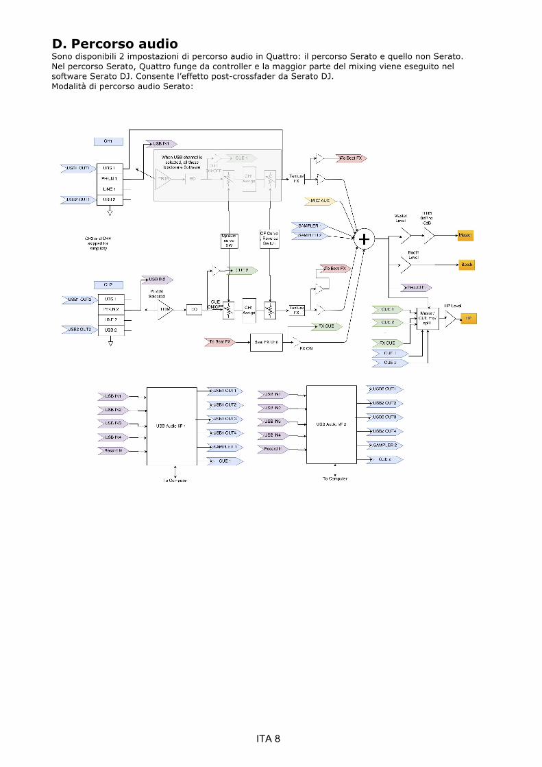
D. Percorso audio Sono disponibili 2 impostazioni di percorso audio in Quattro: il percorso Serato e quello non Serato. Nel percorso Serato, Quattro funge da controller e la maggior parte del mixing viene eseguito nel software Serato DJ. Consente l’effetto post-crossfader da Serato DJ. Modalità di percorso audio Serato:
ITA 8

Nella modalità di percorso non Serato, Quattro funge da mixer hardware esterno classico e il mixing viene eseguito dall’hardware Quattro. Modalità di percorso audio non Serato:
Vi sono diversi modi per passare da un percorso audio all’altro:
1. quando il software Serato DJ è aperto e avviato, farà cambiare a Quattro automaticamente la modalità del percorso in modalità Serato.
2. Premere e tenere premuto il pulsante MASTER e alimentare Quattro. La modalità del percorso audio può essere selezionata e modificata utilizzando l’encoder di selezione FX e la modalità selezionata attualmente viene visualizzata sul display. Ruotare l’encoder di selezione FX per selezionare il percorso audio desiderato e premere per confermare e terminare l’accensione.
3. Quando Quattro è alimentato e in uso, premere e tenere premuto i 2 tasti SHIFT per 5 secondi; un menù utility del sistema verrà visualizzato sul display. Utilizzare l’encoder di selezione FX per selezionare la sezione del percorso audio e il percorso audio desiderato.
L’interfaccia audio è un’interfaccia a 10 ingressi 12 uscite con assegnazione: Canale Ingressi Uscite 1 Deck 1 ingresso S (DVS) Deck 1 uscita S 2 Deck 1 ingresso D (DVS) Deck 1 uscita D 3 Deck 2 ingresso S (DVS) Deck 2 uscita S 4 Deck 2 ingresso D (DVS) Deck 2 uscita D 5 Deck 3 ingresso S (DVS) Deck 3 uscita S 6 Deck 3 ingresso D (DVS) Deck 3 uscita D 7 Deck 4 ingresso S (DVS) Deck 4 uscita S 8 Deck 4 ingresso D (DVS) Deck 4 uscita D 9 Registrazione ingresso S CUE uscita S 10 Registrazione ingresso D CUE uscita D 11 N.D. Campionatore uscita S 12 N.D. Campionatore uscita D 13 N.D. N.D. 14 N.D. N.D. 15 N.D. N.D. 16 N.D. N.D.
ITA 9
E. Menù utility sistema Per accedere al menù utility del sistema, premere e tenere premuto i 2 tasti SHIFT mentre Quattro è in funzione. Il menù verrà visualizzato sul display. Utilizzare l’encoder di selezione FX per scorrere le diverse opzioni e premere sull’encoder per selezionare e modificare le impostazioni: 1. Percorso audio Selezionare il percorso audio Serato e non Serato 2. Intensità crossfader Selezionare l’impostazione crossfader lineare o power crossfader. Questa azione aggiornerà anche la selezione legata al software Serato DJ sia sul collegamento USB 1 sia USB 2. 3. Versione firmware Visualizzazione della versione firmware. 4. Uscire la menù utility del sistema Premere l’encoder di selezione FX per uscire dal menù utility del sistema.
F. Aggiornamento del firmware
Mixars continuerà ad apportare migliorie al prodotto e ad eliminare i bug rilasciando un nuovo firmware per la produzione. Il nuovo firmare e il software di aggiornamento del firmware possono essere scaricati dal sito della Mixars (http://www.mixars.com). Procedura di aggiornamento del firmware: 1. Scaricare lo strumento di aggiornamento del firmware e l’ultimo firmware dal sito della Mixars. 2. Collegare il cavo USB al computer. 3. Premere e tenere premuto il pulsante FX CUE e TAP e avviare l’accensione. Il display visualizzerà
“FIRMWARE UPDATE” (recupero firmware) e Quattro entrerà in modalità aggiornamento del firmware.
4. Aprire il software di aggiornamento del firmware e individuare il file di aggiornamento del firmware.
5. Seguire le istruzioni a video per avviare l’aggiornamento del firmware e attendere il messaggio di richiesta di completamento dell’aggiornamento
6. Effettuare l’accensione di Quattro dopo l’aggiornamento del firmware.
G. Specifiche 1. SEZIONE GENERALE
Alimentazione CA 100~240V 50Hz/60Hz Dimensioni 320(L) x 362(P) x 107(H) mm Consumo 20W Peso 5,35Kg
2. CONDIZIONI DI PROVA STANDARD Temperatura ambiente 23 +/- 2°C Umidità relativa 65% +/- 5% NOTA: le misurazioni possono essere effettuate a una temperatura compresa tra 5°C e 35°C e a un’umidità relativa tra il 45% e l’85%.
3. IMPEDENZA E SENSIBILITÀ INGRESSO/USCITA: (1KHz, EQ FLAT, MAX. GUADAGNO) 3-1. IMPEDENZA DI INGRESSO E LIVELLO INGRESSO DI RIFERIMENTO:
LINEA: 47KΩ /-14dBV (200mV) PHONO: 47KΩ /-50dBV (3.16mV) MIC: 5KΩ/-54dBV (2mV) RITORNO: 47KΩ /-20dBV (100mV) USB -12dBFS
3-2. IMPEDENZA DI USCITA E LIVELLO USCITA DI RIFERIMENTO: MASTER(XLR): 600 OHM / 0dBV (1V) ± 2dB (segnale a segnale 600 ohm) CABINA: 600 OHM / 0dBV (1V) ± 2dB (segnale a segnale 600 ohm) MASTER(RCA): 1K OHM / 0dBV (1V) ± 1dB (carico=100K ohm) REGISTRAZIONE: 1K OHM / -9dBV (355mV) ± 1dB (carico=100K ohm) INVIO: 1K OHM / -14dBV (200mV) ± 1dB (carico=100K ohm) PHONO: 32 OHM / -3dBV (708mV) ± 1dB (carico=32 ohm)
ITA 10

4. GUADAGNO MASSIMO: (EQ FLAT, LIVELLO INGRESSO DI RIFERIMENTO, MAX. GUADAGNO) USCITA CABINA�MASTER (XLR): LINEA: +14dB (a 600Ω) ± 1dB PHONO: +50dB (a 600Ω) ± 2dB MIC: +54dB (a 600Ω) ± 2dB RITORNO: +20dB (a 600Ω) ± 1dB USCITA MASTER(RCA): LINEA: +14dB (a 100KΩ) ± 1dB PHONO: +50dB (a 100KΩ) ± 2dB MIC: +54dB (a 100KΩ) ± 2dB RITORNO: +20dB (a 600Ω) ± 1dB USCITA REGISTRAZIONE: LINEA: +5dB (a 100KΩ) ± 1dB PHONO: +41dB (a 100KΩ) ± 2dB MIC: +45dB (a 100KΩ) ± 2dB RITORNO: +11dB (a 600Ω) ± 1dB USCITA INVIO: LINEA: +0dB (a 100KΩ) ± 1dB PHONO: +36dB (a 100KΩ) ± 2dB MIC: +40dB (a 100KΩ) ± 2dB
5. INGRESSO MASSIMO: (EQ FLAT, MIC, TRIM, MASTER A ORE 9, REGOLAZIONE LIVELLO INGRESSO 1KHz A LIVELLO USCITA INFERIORE ALL’1% T.H.D CON A-w/20KHz LPF) LINEA: SUPERIORE A +15dBV THD<1% RITORNO: SUPERIORE A +9dBV THD<1% PHONO: SUPERIORE A -21dBV THD<1% MIC: SUPERIORE A -25dBV THD<1%
6. USCITA MASSIMA: (INGRESSO LINEA,EQ FLAT, MIC, TRIM, MASTER AL MASSIMO, REGOLAZIONE LIVELLO INGRESSO 1KHz A LIVELLO USCITA INFERIORE ALL’1% CON A-w/20kHz LPF) MASTER(XLR): SUPERIORE A +17dBV CARICO=600Ω THD<1% CABINA: SUPERIORE A +17dBV CARICO=600Ω THD<1% MASTER(RCA): SUPERIORE A +17dBV CARICO=100KΩ THD<1% REGISTRAZIONE: SUPERIORE A +8 dBV CARICO=100KΩ THD<1% INVIO: SUPERIORE A +3dBV CARICO=100KΩ THD<1% PHONO: SUPERIORE A +4dBV CARICO=32Ω THD<1%
7. RISPOSTA IN FREQUENZA: (EQ FLAT, PHONO A -60dB/ALTRO LIVELLO INGRESSO DI RIFERIMENTO, MIC, TRIM, MASTER AL MASSIMO) LINEA: 20 - 20KHz +2/-3dB MIC: 20 - 20KHz +2/-3dB PHONO: 20 - 20KHz +2/-3dB USB: 20 - 20KHz (48K/24b-1KHz�20Hz�20KHz.WAV) +2/-3dB
8. THD + N: (INGRESSO 1KHz, TRIM E MASTER MIC A ORE 12 CON A-w./20KHz LPF) LINEA: 0,01% A INGRESSO 0dB RITORNO: 0,01% A INGRESSO 0dB PHONO: 0,02% A INGRESSO - 36dB MIC: 0,03% A INGRESSO - 40dB
9. RAPPORTO S/N: (INGRESSO 1KHz, TRIM, MIC/AUX, MASTER A ORE 12 CON A-w./20KHz LPF, INGRESSO CORTO QUANDO NON C’È SEGNALE) LINEA: 81dB A INGRESSO 0dB RITORNO: 81dB A INGRESSO 0dB PHONO: 81dB A INGRESSO - 36dB MIC: 74dB A INGRESSO - 40dB
10. CROSSTALK: (INGRESSO 1KHz, TRIM, MIC/AUX, MASTER A ORE 12 CON A-w./20KHz LPF, INGRESSO CORTO QUANDO NON C’È SEGNALE) LINEA: SUPERIORE A 81dB A OGNI INGRESSO CANALE A INGRESSO 0dB PHONO: SUPERIORE A 81dB A OGNI INGRESSO CANALE A INGRESSO -36dB
11. SEPARAZIONE CANALE S&D: (INGRESSO 1KHz, TRIM, MIC/AUX, MASTER A ORE 12 CON A-w./LPF 20KHz, INGRESSO CORTO QUANDO NON C’È SEGNALE) LINEA: SUPERIORE A 81dB TRA CANALE S E D A INGRESSO 0dB PHONO: SUPERIORE A 81dB TRA CANALE S E D A INGRESSO - 36dB
ITA 11

12. RISPOSTA EQUALIZZATORE: (LIVELLO INGRESSO RIFERIMENTO, MIC/AUX, TRIM MASTER AL MASSIMO CON LPF 20KHz) LINEA: (1) Banda Bassa: (la frequenza centrale della Banda Bassa è 70Hz)
Livello massimo: +12 ± 1dB (a 70Hz) Livello minimo: -25 ± 1dB (a 70Hz)
(2) Banda Media: (la frequenza centrale della Banda Media è 1KHz) Livello massimo: +12 ± 1dB (a 1KHz) Livello minimo: -25 ± 1dB (a 1KHz)
(3) Banda Alta: (la frequenza centrale della Banda Alta è 13KHz) Livello massimo: +12 ± 1dB (a 13KHz) Livello minimo: -25 ± 1dB (a 13KHz)
MIC� Alto: -28dB ± 2dB A 100Hz Basso: -28dB ± 2dB A 10KHz
13. Fader Kill: (LIVELLO INGRESSO 0dB 1KHz, TRIM/MASTER A ORE 12 SW MIC OFF CON A-w/ LPF 20KHz) Fader canale: SUPERIORE A 91dB A 1KHz Cross Fader: SUPERIORE A 91dB A 1KHz
14. DIFFERENZA DI LIVELLO S&D: (LIVELLO INGRESSO RIFERIMENTO 1KHz, TRIM, MASTER AL MASSIMO CON A-w/LPF 20KHz) LINEA: ±1dB PHONO: ±1.5dB
15. NOTE (1) Le specifiche sono soggette a variazioni. (2) I componenti sono soggetti a variazioni migliorative all’interno dei campi delle specifiche.
ITA 12

FRA 1
Instructions sur la sécurité
1. Lire ces instructions. 2. Conserver ces instructions. 3. Respecter tous les avertissements. 4. Suivre toutes les instructions. 5. Ne pas utiliser cet appareil à proximité d’eau. 6. Nettoyer uniquement avec un chiffon sec. 7. N’obstruer aucune des ouvertures de ventilation. Installer conformément aux instructions du fabricant. 8. Ne pas installer à proximité de sources de chaleur telles que des radiateurs, des grilles de chauffage, des poêles ou d’autres appareils (y compris des amplificateurs) qui dégagent de la chaleur. 9. Ne pas essayer de contourner les caractéristiques de sécurité de la prise polarisée. Une prise polarisée présente deux broches dont l’une est plus large que l’autre. La broche plus large est destinée à votre sécurité. Si la prise fournie ne s’adapte pas à votre prise murale, contacter un électricien pour qu’il remplace la prise murale obsolète. 10. Protéger le câble d'alimentation pour qu'il ne soit pas piétiné ou coincé, particulièrement au niveau des fiches de connexion, des prises de courant, et de leur point de sortie de l’appareil. 11. N’utiliser que des connexions / accessoires spécifiés par le fabricant. 12. N’utiliser qu’avec le chariot, le pied, le trépied, le rack ou la table spécifiés par le fabricant, ou vendus avec l’appareil. Lorsqu’un chariot est usé, faire preuve de prudence en déplaçant l’ensemble chariot / appareil pour éviter de se blesser s’il bascule. 13. Débrancher l’appareil pendant les orages ou s’il reste inutilisé pendant de longues périodes. 14. Confier toute opération de maintenance à un personnel qualifié. Une maintenance est nécessaire quel que soit le type de dommage subi par l’appareil, comme un cordon d’alimentation ou une prise endommagés, un liquide renversé ou des objets qui seraient tombés dedans, si l’appareil a été exposé à la pluie ou à l’humidité, ne fonctionne pas normalement ou est tombé. 15. AVERTISSEMENT : Afin de réduire le risque d’incendie ou d’électrocution, ne pas exposer cet appareil à la pluie ou à l’humidité. 16. Puisqu’un connecteur est utilisé en tant que dispositif de sectionnement, celui-ci doit toujours rester accessible. 17. La ventilation ne doit pas être entravée par des objets recouvrant les ouvertures de ventilation, comme des journaux, des nappes, des rideaux etc. 18. Ne poser sur l’appareil aucune source de flamme nue comme des bougies allumées. 19. L’appareil doit être utilisé dans une atmosphère tempérée. 20. L’appareil ne doit pas être exposé à un écoulement goutte à goutte ou à des éclaboussures, et aucun objet rempli de liquide, tel qu’un vase, ne doit être posé sur l’appareil.
Le point d’exclamation dans un triangle équilatéral est destiné à avertir l’utilisateur de l’existence d’instructions importantes pour le fonctionnement et la maintenance (entretien) dans la documentation accompagnant cet appareil.
AVERTISSEMENT Afin de réduire le risque d’incendie ou d’électrocution, ne pas exposer cet appareil à la pluie ou à l’humidité. L’appareil ne doit pas être exposé à un écoulement goutte à goute ou à des éclaboussures, et aucun objet rempli de liquide, tel qu’un vase, ne doit être posé sur l’appareil.
L’éclair fléché dans le triangle équilatéral est destiné à avertir l’utilisateur de la présence d’une « tension dangereuse » non isolée dans le boîtier du produit ayant une magnitude suffisante pour constituer un risque d’électrocution.
PRÉCAUTION Pour limiter le risque d’électrocution, ne retirer aucun cache. L’appareil ne contient aucune pièce réparable par l’utilisateur. Ne confier la maintenance qu’à un personnel qualifié.
PRÉCAUTION Pour prévenir tout risque d’électrocution, ne pas utiliser de rallonge sur la prise polarisée, la prise murale ou autre connecteur à moins que les broches ne puissent être entièrement insérées et ainsi ne pas être exposées.

A. Installation des accessoires et du pilote
Vérifiez toutes les pièces suivantes comprises dans l’emballage faisant partie
de l’unité principale :
1 x Guide pour le matériel 1 x câble USB 1 x Cordon d’alimentation en
CA
Installation du pilote
Mac
Aucun pilote nécessaire
Windows
Téléchargez le pilote via notre site Internet : www.mixars.com
Faites un double clic sur le fichier .exe pour commencer l’installation et suivez les instructions
à l’écran.
Veuillez remarquer que vous devez rebrancher le Quattro après l’installation.
Le Mixars Quattro est un dispositif compatible avec Mac OS X mais nécessitera toutefois des pilotes pour Windows.
Veuillez vous assurer que l’installation du pilote est terminée avant d’utiliser le Serato DJ.
FRA 2
B. Commandes et fonctionnalités Arrière
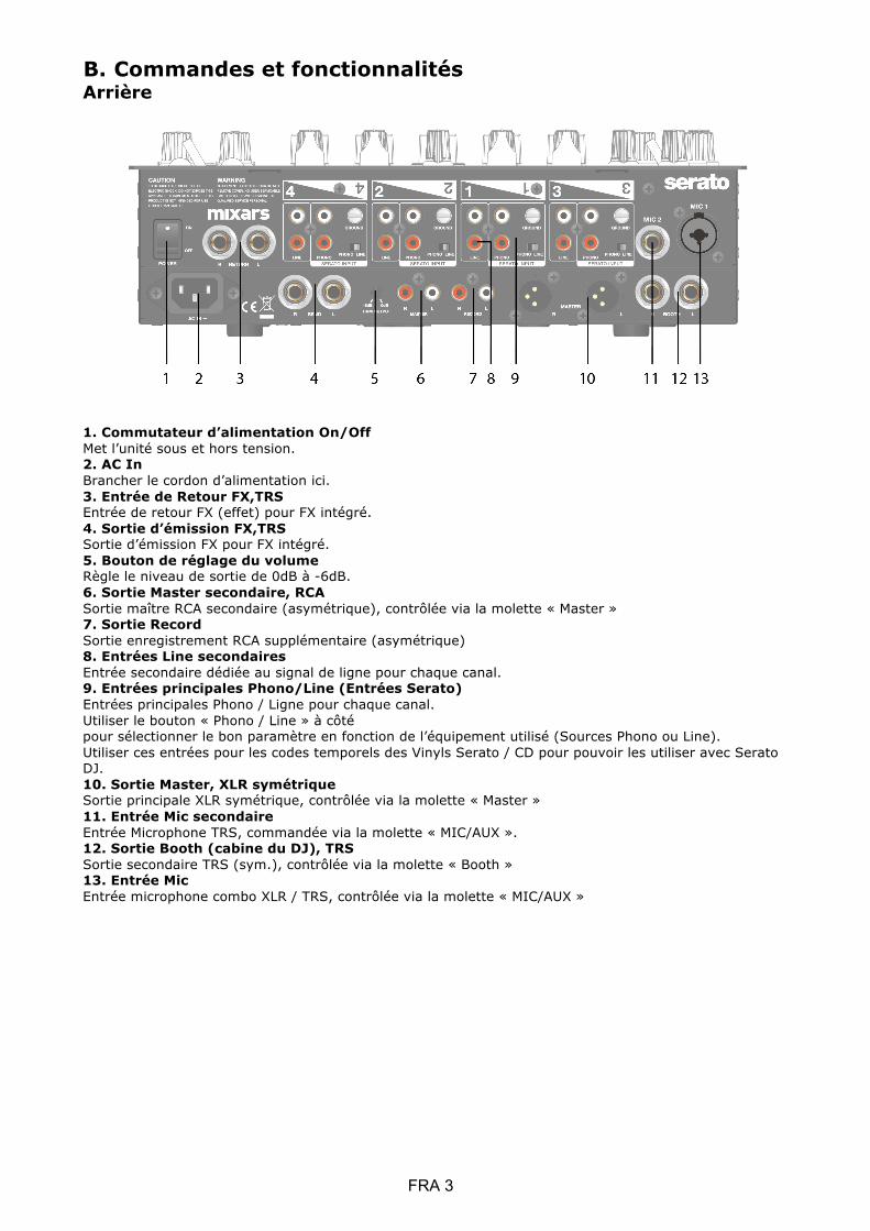
1. Commutateur d’alimentation On/Off Met l’unité sous et hors tension. 2. AC In Brancher le cordon d’alimentation ici. 3. Entrée de Retour FX,TRS Entrée de retour FX (effet) pour FX intégré. 4. Sortie d’émission FX,TRS Sortie d’émission FX pour FX intégré. 5. Bouton de réglage du volume Règle le niveau de sortie de 0dB à -6dB. 6. Sortie Master secondaire, RCA Sortie maître RCA secondaire (asymétrique), contrôlée via la molette « Master » 7. Sortie Record Sortie enregistrement RCA supplémentaire (asymétrique) 8. Entrées Line secondaires Entrée secondaire dédiée au signal de ligne pour chaque canal. 9. Entrées principales Phono/Line (Entrées Serato) Entrées principales Phono / Ligne pour chaque canal. Utiliser le bouton « Phono / Line » à côté pour sélectionner le bon paramètre en fonction de l’équipement utilisé (Sources Phono ou Line). Utiliser ces entrées pour les codes temporels des Vinyls Serato / CD pour pouvoir les utiliser avec Serato DJ. 10. Sortie Master, XLR symétrique Sortie principale XLR symétrique, contrôlée via la molette « Master » 11. Entrée Mic secondaire Entrée Microphone TRS, commandée via la molette « MIC/AUX ». 12. Sortie Booth (cabine du DJ), TRS Sortie secondaire TRS (sym.), contrôlée via la molette « Booth » 13. Entrée Mic Entrée microphone combo XLR / TRS, contrôlée via la molette « MIC/AUX »
FRA 3

Dessus
14. Commutateur Mic Talkover/ On/ Off Bascule de Mic 1 vers Talkover, mode On ou off. 15. Commutateur de sélection de platine Sélectionner la platine de destination [Deck 3/1 et Deck 2/4] pour la zone de commande MIDI correspondante [Gauche / Droite]. 16. Loop / Loop roll Contrôle la fonction de boucle et de boucle répétée dans Serato DJ en tournant et appuyant sur la molette. Appuyer et maintenir le bouton « SHIFT » (voir 22) pour contrôler la fonction loop roll. 17. Library, commandes Load Bibliothèque : Fait défiler Library (bibliothèque) en tournant la molette et affiche le niveau suivant ou charge le morceau sélectionné en appuyant dessus. Maintenir « Shift » et appuyer pour revenir au niveau précédent. 18. Bouton Sampler Bascule entre les micro-pavés de performance et le mode Sampler. Maintenir « Shift » et appuyer pour passer en mode User (utilisateur). 19. Bouton CUES Bascule entre les micro-pavés de performance et le mode CUES. Maintenir « Shift » et appuyer pour passer au mode Transport.
FRA 4

20. Micro-pavés Performance Utiliser pour déclencher des points de repère, des échantillons, des commandes de transport ou autres fonctions définies par l’utilisateur du Serato DJ. 21. Bouton Sync Synchronise une piste avec une autre en appuyant sur le bouton « Sync » correspondant et en désactivant la fonction en appuyant sur « Sync » tout en maintenant « Shift ». 22. Bouton Shift Maintenir pour activer les fonctions décalées de certaines commandes 23. Commutateur de courbe de fondu-enchaîné du Crossfader Basculer entre les 3 paramètres de fondu-enchaîné allant de Hard (courbe ascendante forte, vers la gauche) à Soft (courbe ascendante douce, vers la droite) pour les diverses applications. 24. Commutateur On/Off Split Cue S’il est activé, les signaux des écouteurs sont fractionnés : Signal maître sur un canal, et les signaux Cue (repères) activés sélectionnés via les boutons « CUE » (voir 43), sur l’autre canal. 25. Commutateur Crossfader Reverse Intervertit le canal droit avec le gauche sur le crossfader. 26. CUE Mix Tourner pour l’ajustage entre le signal Cue (point d’entrée verrouillé) et Master sur la sortie écouteur. 27. Commutateur de courbe ascendante du fader Basculez entre les 3 paramètres de fondu-enchaîné allant de Hard (courbe ascendante forte, vers la gauche) à Soft (courbe ascendante douce, vers la droite) pour les diverses applications. 28. Équilibrage Headphones Ajuste le volume des écouteurs. 29. Connecteur de sortie Headphones jack de 6,35 mm et 3,5 mm pour le branchement des écouteurs 30. Commutateur Master On CUE Appuyer pour activer le Master sur le canal écouteur CUE. 31. Volume du Sampler Contrôle le volume de l’échantillonneur dans Serato DJ 32. Crossfader Fait un fondu-enchaîné entre les canaux audio droit et gauche qui leur sont assignés par le « Commutateur d’attribution de canal » (voir 41) 33. Commutateur FX ON Active / désactive le signal de reprise FX (effet) vers la sortie maître. 34. Bouton TAP Tapoter pour entrer le BPM manuel dans l’unité FX. Appuyer et maintenir pendant 3 secondes pour activer la détection auto BPM. 35. Commutateur FX CUE Active / désactive le signal de reprise FX vers la sortie repère (cue) écouteur. 36. Molette de paramètre de profondeur FX Règle la profondeur du signal FX ou le paramètre dry/wet (d’origine / avec effet) du FX sélectionné. 37. Codeur de sélection FX Tourner pour sélectionner divers FX et appuyer pour sélectionner. 38. Molette FX du paramètre Time Ajuste le paramètre de temps FX / beat du FX sélectionné. Appuyer pour basculer entre le paramètre Time et Beat. 39. FX sur le sélecteur Channel Sélectionner le canal souhaité auquel appliquer le FX. 40. Affichage FX intégré Affiche diverses informations sur le FX 41. Commutateur d’attribution de canal Attribue le canal correspondant au canal gauche ou droit du crossfader. Lorsque « THRU » est sélectionné, le signal du canal traverse directement vers le maître en shuntant le crossfader. 42. Curseurs de canaux Règlent le niveau du volume du canal correspondant. 43. Cue On/Off Assignent le canal correspondant au signal Cue (repère). 44. Molette FX de texture du canal son (FILTER) Ajuste le paramètre / niveau de texture FX (effet) du son sélectionné. 45. Mesure du niveau du canal Affiche le niveau de signal du canal correspondant 46. EQ de canal Ajuste les paramètres de l’égaliseur du canal correspondant 47. Channel Trim (ajusteur de séquence) Ajuste le niveau général du canal correspondant. 48. Commutateur Source Sélectionne l’entrée à contrôler sur le canal correspondant. Bascule entre Phono / Line (voir 9), Line (voir 8), Serato – USB1 (voir 50) ou Serato – USB2 (voir 49). Pour la platine 4, il y a une entrée source supplémentaire du MIC 2.
FRA 5

49. Connecteur USB 2 Connecter le mixer à votre ordinateur à l’aide du câble USB fourni pour pouvoir l’utiliser avec Serato DJ. Pour utiliser ce dispositif USB, utiliser le « Commutateur Source » (voir 48) pour sélectionner l’USB2 50. Connecteur USB 1 Connecter le mixer à votre ordinateur à l’aide du câble USB fourni pour pouvoir l’utiliser avec Serato DJ. Pour utiliser ce dispositif USB, utiliser le « Commutateur Source » (voir 48) pour sélectionner l’USB1 51. Volume Master Règle le volume du niveau de signal maître. 52. Jauge de niveau Master Affiche le niveau du signal maître. 53. Booth Ajuste le niveau de la sortie « Booth » (cabine du DJ). 54. Commutateur de sélection de texture de son FX. Bascule entre l’effet filtre, bruit blanc, écrasement et écho, et commande le paramètre FX par la « Molette FX de texture du canal son » (voir 44) 55. Commande Tone de Mic 1 Contrôle la tonalité du mic 1. 56. Commande de volume Mic 1 Contrôle le volume du mic 1.
C. Commandes et fonctionnalités FX intégrées Le Quattro fournit une unité FX à BPM synchronisé pour ajouter des effets spéciaux à la performance. Il y a 15 sélections FX : Filtre Flanger (décalage
temporel du signal)
Delay (retard) Echo (Écho) Reverb (réverbération)
Transformer (interrupteur de son)
Pitch (modifie le pitch d’un octave)
Loop roll (boucle répétée)
Reverse Roll (boucle inversée)
Noise (bruit blanc)
Bit Crusher (impression de battement écrasé)
Gate (compression pour réduire le bruit)
Tape Delay (délai de la bande)
Vinyl Brake (frein vinyle)
Send/return (envoi / retour de boucle)
L’écran de Quattro indique diverses informations sur les fonctions FX :
1. Le nom de l’effet (FX) L’effet actuellement sélectionné est indiqué. Tourner le codeur de sélection FX sur un effet différent, le nom du nouvel effet clignote. Appuyer sur le codeur pour sélectionner l’effet et le nom affiché cesse de clignoter.
2. BPM (battement par minute) Le BPM actuel est indiqué. Tapoter le bouton TAP pour entrer un BPM manuel. Maintenir le bouton TAP enfoncé pendant 3 secondes pour activer Auto BPM, l’affichage indique « AUTO BPM » pendant 2 secondes.
3. Paramètre Beat / Time le paramètre Battement / Temps est indiqué. Appuyer sur le codeur TIME pour basculer la sélection entre les paramètres Beat et Time.
Les molettes TIME et DEPTH contrôlent différents paramètres pour les divers FX :
Effet Fonction de contrôle du temps Fonction de contrôle de la profondeur
Filtre Gamme de battements : 1/4 à 64/1 Gamme de temps : 10ms à 32000ms (lorsque cela dépasse 9999ms, le format « a.bs » sera affiché dans l’affichage normal. (Par ex. « 32s » pour 32 000ms)
Profondeur (Dry/Wet) 0 à 100%
Flanger (décalage temporel du signal)
Gamme de battements : 1/4 à 64/1 Gamme de temps : 10ms à 32000ms (lorsque cela dépasse 9999ms, le format « a.bs » sera affiché dans l’affichage
Profondeur (Dry/Wet) 0 à 100%
FRA 6
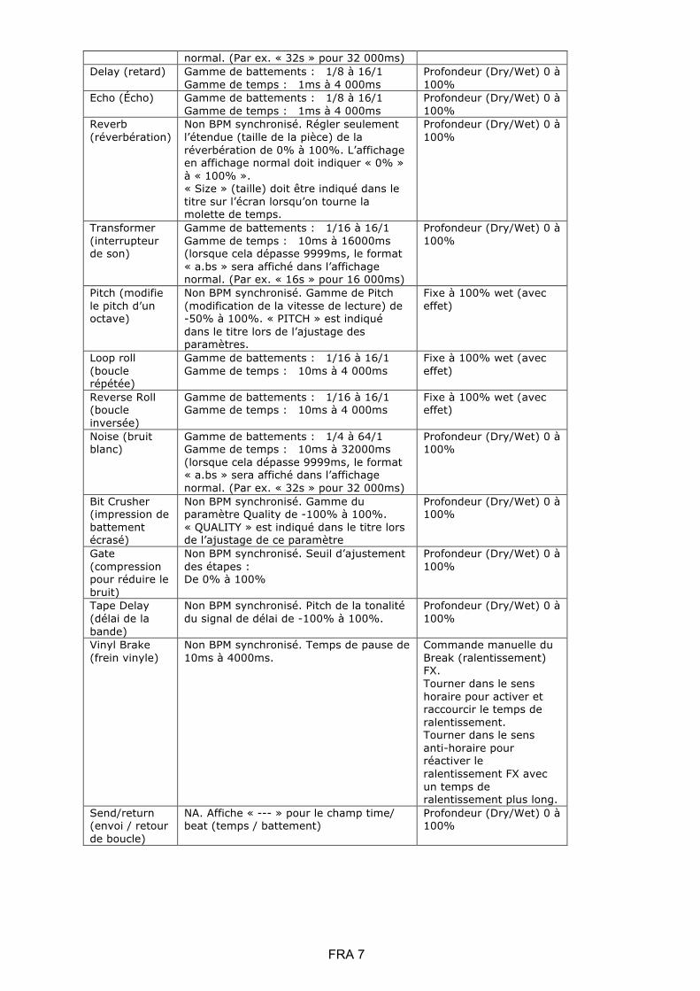
normal. (Par ex. « 32s » pour 32 000ms) Delay (retard) Gamme de battements : 1/8 à 16/1
Gamme de temps : 1ms à 4 000ms Profondeur (Dry/Wet) 0 à 100%
Echo (Écho) Gamme de battements : 1/8 à 16/1 Gamme de temps : 1ms à 4 000ms
Profondeur (Dry/Wet) 0 à 100%
Reverb (réverbération)
Non BPM synchronisé. Régler seulement l’étendue (taille de la pièce) de la réverbération de 0% à 100%. L’affichage en affichage normal doit indiquer « 0% » à « 100% ». « Size » (taille) doit être indiqué dans le titre sur l’écran lorsqu’on tourne la molette de temps.
Profondeur (Dry/Wet) 0 à 100%
Transformer (interrupteur de son)
Gamme de battements : 1/16 à 16/1 Gamme de temps : 10ms à 16000ms (lorsque cela dépasse 9999ms, le format « a.bs » sera affiché dans l’affichage normal. (Par ex. « 16s » pour 16 000ms)
Profondeur (Dry/Wet) 0 à 100%
Pitch (modifie le pitch d’un octave)
Non BPM synchronisé. Gamme de Pitch (modification de la vitesse de lecture) de -50% à 100%. « PITCH » est indiqué dans le titre lors de l’ajustage des paramètres.
Fixe à 100% wet (avec effet)
Loop roll (boucle répétée)
Gamme de battements : 1/16 à 16/1 Gamme de temps : 10ms à 4 000ms
Fixe à 100% wet (avec effet)
Reverse Roll (boucle inversée)
Gamme de battements : 1/16 à 16/1 Gamme de temps : 10ms à 4 000ms
Fixe à 100% wet (avec effet)
Noise (bruit blanc)
Gamme de battements : 1/4 à 64/1 Gamme de temps : 10ms à 32000ms (lorsque cela dépasse 9999ms, le format « a.bs » sera affiché dans l’affichage normal. (Par ex. « 32s » pour 32 000ms)
Profondeur (Dry/Wet) 0 à 100%
Bit Crusher (impression de battement écrasé)
Non BPM synchronisé. Gamme du paramètre Quality de -100% à 100%. « QUALITY » est indiqué dans le titre lors de l’ajustage de ce paramètre
Profondeur (Dry/Wet) 0 à 100%
Gate (compression pour réduire le bruit)
Non BPM synchronisé. Seuil d’ajustement des étapes : De 0% à 100%
Profondeur (Dry/Wet) 0 à 100%
Tape Delay (délai de la bande)
Non BPM synchronisé. Pitch de la tonalité du signal de délai de -100% à 100%.
Profondeur (Dry/Wet) 0 à 100%
Vinyl Brake (frein vinyle)
Non BPM synchronisé. Temps de pause de 10ms à 4000ms.
Commande manuelle du Break (ralentissement) FX. Tourner dans le sens horaire pour activer et raccourcir le temps de ralentissement. Tourner dans le sens anti-horaire pour réactiver le ralentissement FX avec un temps de ralentissement plus long.
Send/return (envoi / retour de boucle)
NA. Affiche « --- » pour le champ time/ beat (temps / battement)
Profondeur (Dry/Wet) 0 à 100%
FRA 7

D. Routage Audio Il y a 2 paramètres de routage audio dans Quattro, à savoir le routage Serato et le routage non-Serato. En routage mode Serato, le Quattro agit en tant que contrôleur et la plus grande partie du mixage est réalisée dans le logiciel Serato DJ. Il autorise l’effet post-crossfader (post-fondu-enchaîné) depuis Serato DJ. Le routage audio en mode Serato :
FRA 8

En mode de routage non Serato, le Quattro fonctionne comme une table de mixage externe classique dont le mixage est effectué par un matériel Quattro. Le mode de routage audio non Serato :
Il y a deux façons différentes pour basculer entre les deux routages audio :
1. Lorsque le logiciel Serato DJ est ouvert et initialisé, il va déclencher le Quattro connecté pour qu’il modifie le mode de routage Serato automatiquement.
2. Appuyer et maintenir le bouton MASTER et mettre le Quattro sous tension. Le mode de routage audio peut être sélectionné et modifié en utilisant le codeur de sélection FX, le mode sélectionné s’affiche à l’écran. Faire tourner le codeur de sélection FX jusqu’au routage audio souhaité et appuyer pour confirmer et terminer la mise sous tension.
3. Lorsque le Quattro est sous tension et opérationnel, appuyer et maintenir les 2 boutons SHIFT pendant 5 secondes, un utilitaire du menu système s’affiche à l’écran. Utiliser le codeur de sélection FX pour sélectionner la section du routage audio et sélectionner le routage audio désiré.
L’interface audio est une interface 10 entrées/12 sorties avec attribution : CH Entrées Sorties 1 Platine 1 entrée G (DVS) Platine 1 sortie G 2 Platine 1 entrée D (DVS) Platine 1 sortie D 3 Platine 2 entrée G (DVS) Platine 2 sortie G 4 Platine 2 entrée D (DVS) Platine 2 sortie D 5 Platine 3 entrée G (DVS) Platine 3 sortie G 6 Platine 3 entrée D (DVS) Platine 3 sortie D 7 Platine 4 entrée G (DVS) Platine 4 sortie G 8 Platine 4 entrée D (DVS) Platine 4 sortie D 9 Enregistrement entrée G CUE sortie G 10 Enregistrement entrée D CUE sortie D 11 NA Échantillonneur sortie G 12 NA Échantillonneur sortie D 13 NA NA 14 NA NA 15 NA NA 16 NA NA
FRA 9

E. System Utility Menu (Menu système utilitaire) Pour entrer dans le Menu système utilitaire, appuyer et maintenir les 2 boutons SHIFT lorsque le Quattro est en cours de fonctionnement. Le menu s’affiche à l’écran. Utiliser le codeur de sélection FX pour parcourir les différentes options et appuyer sur le codeur pour sélectionner les paramètres et les modifier : 1. Routage Audio Sélectionner entre le routage audio Serato et non-Serato 2. Puissance du Crossfader Sélectionner les paramètres linéaire et puissance du crossfader. Cela mettra aussi à jour la sélection dans le logiciel Serato DJ connecté à la fois sur la connexion USB 1 et USB 2. 3. Version micrologicielle Afficher la version micrologicielle. 4. Sortir du menu système utilitaire Appuyer sur le codeur de sélection FX pour sortir du menu système utilitaire.
F. Mise à jour du micrologiciel
Mixars va continuer à améliorer le produit et de réparer les bogues en éditant un nouveau micrologiciel au niveau de la production. Le nouveau micrologiciel et l’outil de mise à jour du micrologiciel peuvent être téléchargés sur le site Internet Mixars (http://www.mixars.com). Procédure de mise à jour du micrologiciel : 1. Télécharger l’outil de mise à jour du micrologiciel et le dernier micrologiciel sur le site Internet
Mixars. 2. Connecter le câble USB à l’ordinateur. 3. Appuyer et maintenir le bouton FX CUE et TAP et mettre sous tension. « FIRMWARE UPDATE »
s’affiche à l’écran et le Quattro passe en mode de mise à jour du micrologiciel. 4. Ouvrir le logiciel de mise à jour du micrologiciel et localiser le fichier de mise à jour du
micrologiciel. 5. Suivre les instructions à l’écran pour commencer la mise à jour du micrologiciel et attendre
l’invite de fin de mise à jour. 6. Réinitialiser le Quattro après la mise à jour du micrologiciel.
G. Spécifications 1. SECTION GÉNÉRALE
Tension d’alimentation CA 100~240V 50Hz/60Hz Dimensions 320mm(larg.) x 362mm(prof.) x 107mm(haut.) Consommation 20W Poids 5,35Kg
2. CONDITIONS DE TEST STANDARD Température ambiante 23 +/- 2 °C Humidité relative 65% +/- 5% REMARQUE : Les mesures peuvent être menées entre 5 °C à 35 °C et 45% à 85% d’humidité relative.
3. IMPÉDANCE ENTRÉE / SORTIE ET SENSIBILITÉ : (1KHz,EQ sur FLAT, GAIN sur MAX.) 3-1. IMPÉDANCE D’ENTRÉE ET NIVEAU D’ENTRÉE DE RÉFÉRENCE :
LINE : 47KΩ /-14dBV (200mV) PHONO : 47KΩ /-50dBV (3.16mV) MIC : 5KΩ/-54dBV (2mV) RETOUR : 47KΩ /-20dBV (100mV) USB -12dBFS
3-2. IMPÉDANCE DE SORTIE ET NIVEAU DE SORTIE DE RÉFÉRENCE : MASTER(XLR) : 600 OHM / 0dBV (1V) ± 2dB (Signal à Signal 600 ohm) BOOTH : 600 OHM / 0dBV (1V) ± 2dB (Signal à Signal 600 ohm) MASTER(RCA) : 1K OHM / 0dBV (1V) ± 1dB (charge = 100K ohm) ENREGISTREMENT : 1K OHM / -9dBV (355mV) ± 1dB (charge = 100K ohm) ENVOI : 1K OHM / -14dBV (200mV) ± 1dB (charge = 100K ohm) PHONO : 32 OHM / -3dBV (708mV) ± 1dB (charge = 32 ohm)
FRA 10

4. GAIN MAXIMUM : ( EQ FLAT, NIVEAU D’ENTRÉE DE RÉFÉRENCE, GAIN MAX.) MASTER (XLR)�SORTIE BOOTH : LINE : +14dB (AT 600Ω) ± 1dB PHONO : +50dB (À 600Ω) ± 2dB MIC : +54dB (À 600Ω) ± 2dB RETOUR : +20dB (À 600Ω) ± 1dB SORTIE MASTER(RCA) : LINE : +14dB (À 100KΩ) ± 1dB PHONO : +50dB (À 100KΩ) ± 2dB MIC : +54dB (À 100KΩ) ± 2dB RETOUR : +20dB (À 600Ω) ± 1dB SORTIE ENREGISTREMENT : LINE : +5dB (À 100KΩ) ± 1dB PHONO : +41dB (À 100KΩ) ± 2dB MIC : +45dB (À 100KΩ) ± 2dB RETOUR : +11dB (À 600Ω) ± 1dB SORTIE ENVOI : LINE : +0dB (À 100KΩ) ± 1dB PHONO : +36dB (À 100KΩ) ± 2dB MIC : +40dB (À 100KΩ) ± 2dB
5. ENTRÉE MAXIMUM : (EQ FLAT, MIC, TRIM, MASTER SUR 9 HEURES, RÉGLER LE NIVEAU D’ENTRÉE À 1KHz SUR UN NIVEAU DE SORTIE INFÉRIEUR À 1% de T.H.D AVEC UN LPF de -w/20KHz) LINE : SUPÉRIEURE À +15dBV THD<1% RETOUR : SUPÉRIEURE À +9dBV THD<1% PHONO : SUPÉRIEUR À -21dBV THD<1% MIC : SUPÉRIEUR À -25dBV THD<1%
6. SORTIE MAXIMUM : (ENTRÉE LINE, EQ FLAT ,MIC, TRIM, MASTER SUR MAX, AJUSTER LE NIVEAU D’ENTRÉE 1KHz SUR UN NIVEAU DE SORTIE INFÉRIEUR À 1% AVEC UN LPF de -w/20kHz) MASTER(XLR) : SUPÉRIEUR À +17dBV CHARGE=600Ω THD<1% BOOTH : SUPÉRIEUR À +17dBV CHARGE=600Ω THD<1% MASTER(RCA) : SUPÉRIEUR À +17dBV CHARGE=100KΩ THD<1% ENREGISTREMENT : SUPÉRIEUR À +8 dBV CHARGE=100KΩ THD<1% ENVOI : SUPÉRIEUR À +3dBV CHARGE=100KΩ THD<1% PHONO : SUPÉRIEUR À +4dBV CHARGE=32Ω THD<1%
7. RÉPONSE DE FRÉQUENCE : (EQ FLAT, PHONO À -60dB / AUTRE NIVEAU D’ENTRÉE DE REFERENCE , MIC, TRIM, MASTER SUR MAX.) LINE : 20 - 20KHz +2/-3dB MIC : 20 - 20KHz +2/-3dB PHONO : 20 - 20KHz +2/-3dB USB : 20 - 20KHz (48K/24b-1KHz�20Hz�20KHz.WAV) +2/-3dB
8. THD + N : (ENTRÉE 1KHz, MIC TRIM ET MASTER SUR 12 HEURES, AVEC UN LPF w./20KHz) LINE � 0.01 % À 0dB D’ENTRÉE RETOUR : 0.01 % À 0dB D’ENTRÉE PHONO � 0.02 % À -36dB D’ENTRÉE MIC � 0.03 % À -40dB D’ENTRÉE
9. RATION S/N : (ENTRÉE 1KHz, MIC/AUX, TRIM, MASTER SUR 12 HEURES, AVEC UN LPF-w/20KHz, ENTRÉE EN COURT-CIRCUIT LORSQU’IL N’Y A PAS DE SIGNAL) LINE � 81dB À 0dB D’ENTRÉE RETOUR � 81dB À 0dB D’ENTRÉE PHONO � 81dB À -36dB D’ENTRÉE MIC � 74dB À -40dB D’ENTRÉE
10. CROSSTALK (diaphonie) : (ENTRÉE 1KHz, MIC/AUX, TRIM, MASTER SUR 12 HEURES AVEC UN LPF -w/ 20KHz, ENTRÉE EN COURT-CIRCUIT LORSQU’IL N’Y A PAS DE SIGNAL ) LINE : SUPÉRIEURE À 81dB AVEC ENTRÉE DE CHAQUE CANAL À 0dB D’ENTRÉE PHONO : SUPÉRIEUR À 81dB AVEC ENTRÉE DE CHAQUE CANAL À -36dB D’ENTRÉE
11. SÉPARATION CANAL D et G : (ENTRÉE 1KHz, MIC/AUX, TRIM, MASTER SUR 12HEURES AVEC UN LPF -w/20KHz, ENTRÉE EN COURT-CIRCUIT LORSQU’IL N’Y A PAS DE SIGNAL) LINE : SUPÉRIEURE À 81dB — ENTRÉE ENTRE CANAL D ET G À 0dB PHONO : SUPÉRIEURE À 81dB — ENTRÉE ENTRE CANAL D ET G À -36dB
FRA 11
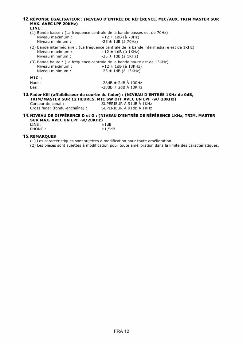
12. RÉPONSE ÉGALISATEUR : (NIVEAU D’ENTRÉE DE RÉFÉRENCE, MIC/AUX, TRIM MASTER SUR MAX. AVEC LPF 20KHz) LINE : (1) Bande basse : (La fréquence centrale de la bande basses est de 70Hz)
Niveau maximum : +12 ± 1dB (à 70Hz) Niveau minimum : -25 ± 1dB (à 70Hz)
(2) Bande intermédiaire : (La fréquence centrale de la bande intermédiaire est de 1KHz) Niveau maximum : +12 ± 1dB (à 1KHz) Niveau minimum : -25 ± 1dB (à 1KHz)
(3) Bande haute : (La fréquence centrale de la bande haute est de 13KHz) Niveau maximum : +12 ± 1dB (à 13KHz) Niveau minimum : -25 ± 1dB (à 13KHz)
MIC � Haut : -28dB ± 2dB À 100Hz Bas : -28dB ± 2dB À 10KHz
13. Fader Kill (affaiblisseur de courbe du fader) : (NIVEAU D’ENTRÉE 1KHz de 0dB, TRIM/MASTER SUR 12 HEURES. MIC SW OFF AVEC UN LPF -w/ 20KHz) Curseur de canal : SUPÉRIEUR À 91dB À 1KHz Cross fader (fondu-enchaîné) : SUPÉRIEUR À 91dB À 1KHz
14. NIVEAU DE DIFFÉRENCE D et G : (NIVEAU D’ENTRÉE DE RÉFÉRENCE 1KHz, TRIM, MASTER SUR MAX. AVEC UN LPF -w/20KHz) LINE : ±1dB PHONO : ±1,5dB
15. REMARQUES (1) Les caractéristiques sont sujettes à modification pour toute amélioration. (2) Les pièces sont sujettes à modification pour toute amélioration dans la limite des caractéristiques.
FRA 12

ESP 1
Instrucciones de seguridad
1. Leer estas Instrucciones. 2. Guardar estas Instrucciones. 3. Respetar todas las Advertencias. 4. Seguir todas las Instrucciones. 5. No utilizar el equipo cerca del agua. 6. Limpiar solo con un paño seco. 7. No obstruir las aberturas de ventilación. Instalar según las instrucciones del fabricante. 8. No instalar cerca de fuentes de calor como radiadores, rejillas de aire caliente, estufas u otros equipos (incluidos los amplificadores) que produzcan calor. 9. No ignorar la función de seguridad del enchufe polarizado. Un enchufe polarizado cuenta con dos clavijas planas, una más ancha que la otra. La clavija ancha garantiza la seguridad de la conexión. Si el enchufe suministrado no es compatible con la toma, contactar con un electricista para sustituir la toma obsoleta. 10. Evitar que el cable de alimentación sea pisoteado o comprimido, en particular en los enchufes, en las tomas y en el punto de salida del equipo. 11. Utilizar solo los accesorios especificados por el fabricante. 12. Usar solo con el carro, poste, trípode, soporte o mesa especificados por el fabricante o vendidos con el equipo. Si se utiliza un carro, prestar atención al desplazarlo con el equipo encima para evitar vuelcos y accidentes. 13. Desconectar el equipo de la alimentación durante tormentas o largos periodos de inutilización. 14. Para la asistencia, dirigirse solo a personal cualificado. El equipo necesita asistencia si ha sufrido algún daño, por ejemplo al cable de alimentación o al enchufe, ha sido mojado por algún líquido o golpeado por un objeto, se ha expuesto a lluvia o humedad, no funciona normalmente o se ha caído. 15. ADVERTENCIA: Para reducir el riesgo de incendio o descargas eléctricas, no se debe exponer este equipo a la lluvia o a la humedad. 16. El conector del dispositivo funciona como dispositivo de desconexión. Por esto, debe ser posible utilizarlo sin problemas. 17. No se debe impedir la ventilación cubriendo las aberturas de ventilación con objetos como periódicos, manteles, cortinas, etc. 18. No se debe colocar ninguna fuente de llamas libres, como velas encendidas, sobre el equipo. 19. El equipo debe utilizarse en climas templados. 20. El equipo non debe exponerse a goteo o salpicaduras y no se deben colocar objetos llenos de líquido, como floreros, encima del mismo.
El signo de exclamación en el triángulo equilátero sirve para llamar la atención del usuario sobre instrucciones de funcionamiento o mantenimiento (asistencia) importantes en la documentación adjunta al equipo.
El símbolo del rayo con la flecha en el triángulo equilátero sirve para advertir al usuario sobre la presencia de "tensión peligrosa" no aislada en la caja del producto, que puede ser suficiente para constituir un riesgo de descarga eléctrica.
ADVERTENCIA Para reducir el riesgo de incendio o descargas eléctricas, no se debe exponer este equipo a la lluvia o a la humedad. El equipo non debe exponerse a goteo o salpicaduras y no se deben colocar objetos llenos de líquido, como floreros, encima del mismo.
ATENCIÓN Para evitar las descargas eléctricas, no utilizar el enchufe polarizado con alargadores, ladrones u otras tomas si las clavijas no caben completamente, para evitar que queden expuestas.
ATENCIÓN Para reducir el riesgo de descargas eléctricas, no quitar las coberturas. El equipo no contiene partes que el usuario pueda reparar. Para la asistencia, dirigirse solo a personal

A. Accesorios e instalació n del software controlador
Comprobar que el paquete de la unidad principal incluya estos componentes:
Guía hardware x 1 Cable USB x 1 Cable AC x 1
Instalació n del controlador del dispositivo
Mac
Ningún controlador necesario
Windows
Descargar el controlador en nuestro sitio web: www.mixars.com
Hacer doble clic en el archivo .exe para iniciar la instalación y seguir las instrucciones
visualizadas.
Podría ser necesario volver a conectar el Quattro después de la instalación.
El Mixars Quattro es un dispositivo con soporte nativo para Mac OS X, mientras que para Windows requiere un software controlador. Asegurarse de completar la instalación de este controlador antes de usar Serato DJ.
ESP 2
B. Mandos y funciones Panel trasero
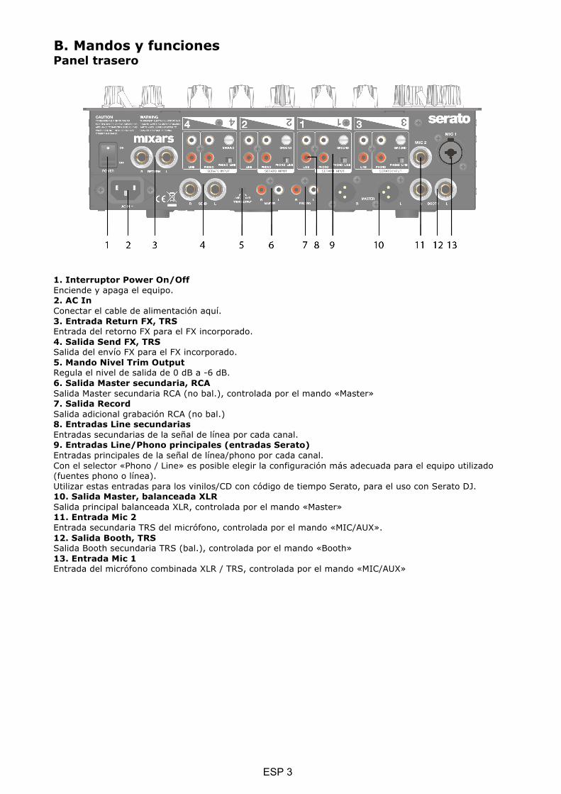
1. Interruptor Power On/Off Enciende y apaga el equipo. 2. AC In Conectar el cable de alimentación aquí. 3. Entrada Return FX, TRS Entrada del retorno FX para el FX incorporado. 4. Salida Send FX, TRS Salida del envío FX para el FX incorporado. 5. Mando Nivel Trim Output Regula el nivel de salida de 0 dB a -6 dB. 6. Salida Master secundaria, RCA Salida Master secundaria RCA (no bal.), controlada por el mando «Master» 7. Salida Record Salida adicional grabación RCA (no bal.) 8. Entradas Line secundarias Entradas secundarias de la señal de línea por cada canal. 9. Entradas Line/Phono principales (entradas Serato) Entradas principales de la señal de línea/phono por cada canal. Con el selector «Phono / Line» es posible elegir la configuración más adecuada para el equipo utilizado (fuentes phono o línea). Utilizar estas entradas para los vinilos/CD con código de tiempo Serato, para el uso con Serato DJ. 10. Salida Master, balanceada XLR Salida principal balanceada XLR, controlada por el mando «Master» 11. Entrada Mic 2 Entrada secundaria TRS del micrófono, controlada por el mando «MIC/AUX». 12. Salida Booth, TRS Salida Booth secundaria TRS (bal.), controlada por el mando «Booth» 13. Entrada Mic 1 Entrada del micrófono combinada XLR / TRS, controlada por el mando «MIC/AUX»
ESP 3

Panel superior
14. Selector Talkover/On/Off micrófono Enciende, apaga o selecciona el modo Talkover para el micrófono 1. 15. Selector Deck Selecciona el deck de destino [Deck 3/1 y Deck 2/4] para el área de control MIDI correspondiente [izquierda/derecha]. 16. Loop / Loop roll Girando y presionando el mando se controlan las funciones loop y loop roll del Serato DJ. Presionar y mantener presionado el botón «SHIFT» (véase 22) para controlar la función loop roll. 17. Mandos Library y Load Library: Desplazarse por la librería girando el mando y visualizar el nivel sucesivo o cargar la canción seleccionada presionándolo. Mantener presionado «Shift» y presionar el mando para volver al nivel anterior. 18. Botón Sampler Configura el modo Sampler en todos los pads. Mantener presionado «Shift» y presionar el botón para pasar al modo Usuario. 19. Botón CUES Configura el modo CUES en todos los pads. Mantener presionado «Shift» y presionar el botón para pasar al modo Transporte.
ESP 4

20. Pads Utilizar los pads para controlar puntos cue, samples, transporte u otras funciones del Serato DJ configuradas. 21. Botón Sync Presionando «Sync» se sincroniza una pista con otra, para desactivar la función volver a presionar «Sync» manteniendo presionado «Shift». 22. Botón Shift Mantenerlo presionado para activar las funciones opuestas de algunos mandos 23. Selector Crossfader Curve Permite seleccionar entre las 3 configuraciones del crossfader, de Hard (duro, a la izquierda) a Soft (suave, a la derecha), según la aplicación. 24. Selector Split Cue On/Off Si está activado, la señal en los auriculares se divide: señal Master en un canal, y señales Cue activadas con los botones «CUE» (véase 43) en el otro. 25. Selector Crossfader Reverse Invierte el canal izquierdo con el derecho en el crossfader. 26. CUE Mix Girar para regular entre señal Cue y Master en la salida de los auriculares. 27. Selector Upfader Curve Permite seleccionar entre las 3 configuraciones del crossfader, de Hard (duro, a la izquierda) a Soft (suave, a la derecha), según la aplicación. 28. Mando Headphones Regula el volumen de los auriculares. 29. Conectores de salida Headphones Conectores jack de 6,35 mm y 3,5 mm para los auriculares. 30. Mando Master en CUE Presionar para activar el Master en el canal CUE de los auriculares. 31. Volumen Sampler Regula el volumen del sampler en el Serato DJ. 32. Crossfader Regula el crossfader entre los canales derecho e izquierdo del audio asignado mediante el «Selector de asignación canal» (véase 41). 33. Interruptor FX ON Activa/desactiva la señal procesada FX en la salida Master. 34. Botón TAP Tocar para introducir manualmente las PPM en la unidad FX. Presionar y mantener presionado durante 3 segundos para activar la detección automática de las PPM. 35. Botón FX CUE Activa/desactiva la señal procesada FX en la salida Cue de los auriculares. 36. Mando FX Depth Regula la profundidad del FX seleccionado o el nivel de señal dry/wet (sin efectos/procesada). 37. Conmutador rotativo FX Select Girar para seleccionar FX distintos y presionar para confirmar. 38. Mando Time Regula el parámetro tiempo/pulsaciones del FX seleccionado. Presionar para pasar de Tiempo a Pulsaciones. 39. Selector FX Channel Selecciona el canal donde aplicar el FX. 40. Pantalla FX integrada Visualiza varios datos sobre el FX. 41. Selector de asignación canal Asigna el canal correspondiente al canal derecho o izquierdo del crossfader. Seleccionando "THRU", la señal del canal llegará directamente al master, saltando el crossfader. 42. Reguladores de los canales Regulan el volumen de los canales correspondientes. 43. Cue On/Off Asigna el canal correspondiente a la señal Cue. 44. Mando FILTER Regula el parámetro / nivel del FX de textura sonora seleccionado. 45. Volumen del canal Visualiza el volumen de la señal del canal correspondiente 46. Ecualizador canal Regula la configuración del ecualizador para el canal correspondiente 47. Mando Trim Regula el nivel general del canal correspondiente. 48. Selector fuente Selecciona la entrada que se controlará en el canal correspondiente. Las opciones posibles son Phono/Line (phono/línea, véase 9), Line (línea, véase 8), Serato – USB1 (véase 50) o Serato – USB2 (véase 49). El Deck 4 también cuenta con la fuente MIC 2.
ESP 5

49. Conector USB 2 Sirve para conectar la mezcladora al ordenador mediante el cable USB para el uso con Serato DJ. Para elegir esta opción, colocar el «Selector fuente» (véase 48) en USB 2. 50. Conector USB 1 Sirve para conectar la mezcladora al ordenador mediante el cable USB para el uso con Serato DJ. Para elegir esta opción, colocar el «Selector fuente» (véase 48) en USB 1. 51. Mando Master Regula el volumen de la señal master. 52. Volumen Master Visualiza el volumen de la señal master. 53. Booth Regula el volumen de la salida «Booth». 54. Selector del FX de textura sonora. Elegir entre el efecto Filter, Noise, Crush y Echo y controlar el parámetro FX mediante el mando «FILTER» (véase 44). 55. Mando Tone Controla el tono del micrófono 1. 56. Mando MIC 1 Controla el volumen del micrófono 1.
C. Mandos y funciones FX integrados El Quattro proporciona una unidad FX sincronizada con PPM para añadir efectos especiales al sonido. Las selecciones de FX disponibles son 15: Filtro Flanger Delay Eco Reverberación Transformador Pitch Loop Roll Reverse Roll Ruido Bit Crusher Gate Tape Delay Vinyl Brake Envío/retorno
La pantalla del Quattro visualiza varios datos sobre el FX:
1. Nombre del FX El FX actualmente seleccionado. Girando el conmutador rotativo FX para pasar a otro FX, el nuevo nombre parpadeará. Al presionar el conmutador para seleccionar el nuevo FX y el nombre en la pantalla dejará de parpadear.
2. BPM Se visualizan las PPM, pulsaciones por minuto, actuales. Tocar el botón TAP para introducir un valor manualmente. Presionar y mantener presionado el botón TAP durante 3 segundos para activar la detección automática, la pantalla visualizará "AUTO BPM" durante 2 segundos.
3. Parámetro Beat/Time Se visualiza el parámetro pulsaciones/tiempo actual. Presionar el conmutador rotativo TIME para pasar del parámetro Pulsaciones al parámetro Tiempo.
Dependiendo del FX, los mandos TIME y DEPTH controlan parámetros distintos:
Efecto Función del mando Time Función del mando Depth Filtro Rango pulsaciones: de 1/4 a 64/1
Rango de tiempo: de 10 ms a 32000 ms (más allá de 9999 ms, se usará el formato “a.bs” en la visualización. Por ej. “32.0s” para 32000 ms)
Profundidad (Dry/Wet) 0-100%
Flanger Rango pulsaciones: de 1/4 a 64/1 Rango de tiempo: de 10 ms a 32000 ms (más allá de 9999 ms, se usará el formato “a.bs” en la visualización. Por ej. “32.0s” para 32000 ms)
Profundidad (Dry/Wet) 0-100%
Delay Rango pulsaciones: de 1/8 a 16/1 Rango de tiempo: de 1 ms a 4000 ms
Profundidad (Dry/Wet) 0-100%
Eco Rango pulsaciones: de 1/8 a 16/1 Rango de tiempo: de 1 ms a 4000 ms
Profundidad (Dry/Wet) 0-100%
Reverberación No sincronizado con PPM. Regular solo la extensión de la reverberación (dimensión de la habitación) de 0% a 100%. La
Profundidad (Dry/Wet) 0-100%
ESP 6
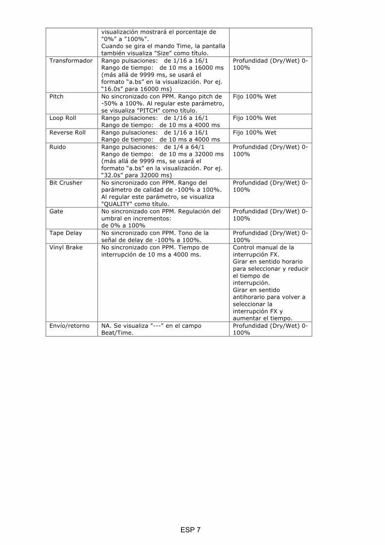
visualización mostrará el porcentaje de "0%" a "100%". Cuando se gira el mando Time, la pantalla también visualiza "Size" como título.
Transformador Rango pulsaciones: de 1/16 a 16/1 Rango de tiempo: de 10 ms a 16000 ms (más allá de 9999 ms, se usará el formato “a.bs” en la visualización. Por ej. “16.0s” para 16000 ms)
Profundidad (Dry/Wet) 0-100%
Pitch No sincronizado con PPM. Rango pitch de -50% a 100%. Al regular este parámetro, se visualiza "PITCH" como título.
Fijo 100% Wet
Loop Roll Rango pulsaciones: de 1/16 a 16/1 Rango de tiempo: de 10 ms a 4000 ms
Fijo 100% Wet
Reverse Roll Rango pulsaciones: de 1/16 a 16/1 Rango de tiempo: de 10 ms a 4000 ms
Fijo 100% Wet
Ruido Rango pulsaciones: de 1/4 a 64/1 Rango de tiempo: de 10 ms a 32000 ms (más allá de 9999 ms, se usará el formato “a.bs” en la visualización. Por ej. “32.0s” para 32000 ms)
Profundidad (Dry/Wet) 0-100%
Bit Crusher No sincronizado con PPM. Rango del parámetro de calidad de -100% a 100%. Al regular este parámetro, se visualiza "QUALITY" como título.
Profundidad (Dry/Wet) 0-100%
Gate No sincronizado con PPM. Regulación del umbral en incrementos: de 0% a 100%
Profundidad (Dry/Wet) 0-100%
Tape Delay No sincronizado con PPM. Tono de la señal de delay de -100% a 100%.
Profundidad (Dry/Wet) 0-100%
Vinyl Brake No sincronizado con PPM. Tiempo de interrupción de 10 ms a 4000 ms.
Control manual de la interrupción FX. Girar en sentido horario para seleccionar y reducir el tiempo de interrupción. Girar en sentido antihorario para volver a seleccionar la interrupción FX y aumentar el tiempo.
Envío/retorno NA. Se visualiza "---" en el campo Beat/Time.
Profundidad (Dry/Wet) 0-100%
ESP 7

D. Enrutamiento de audio Existen 2 opciones de enrutamiento de audio en el Quattro, es decir, el enrutamiento Serato y el enrutamiento no Serato. En el enrutamiento Serato, el Quattro funciona como controlador y la mayoría de las mezclas se realizan en el software Serato DJ. Es posible el FX post-crossfader desde Serato DJ. Enrutamiento de audio modo Serato:
ESP 8
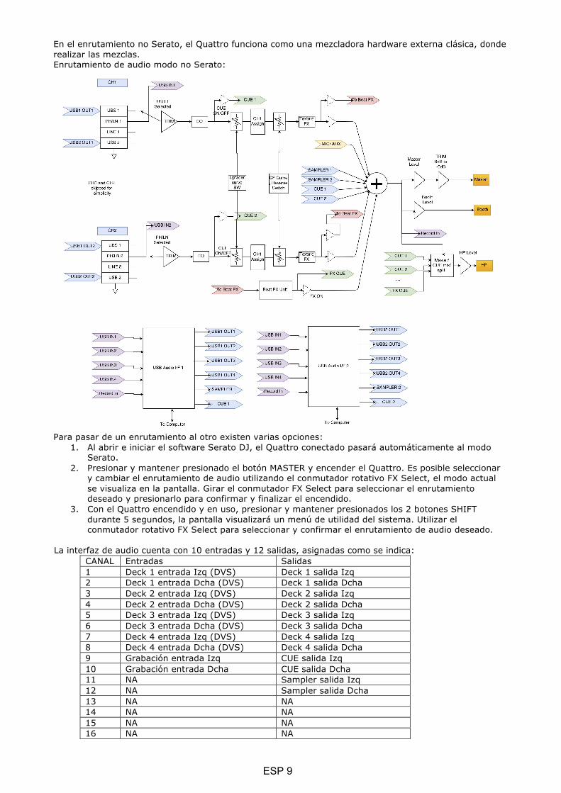
En el enrutamiento no Serato, el Quattro funciona como una mezcladora hardware externa clásica, donde realizar las mezclas. Enrutamiento de audio modo no Serato:
Para pasar de un enrutamiento al otro existen varias opciones:
1. Al abrir e iniciar el software Serato DJ, el Quattro conectado pasará automáticamente al modo Serato.
2. Presionar y mantener presionado el botón MASTER y encender el Quattro. Es posible seleccionar y cambiar el enrutamiento de audio utilizando el conmutador rotativo FX Select, el modo actual se visualiza en la pantalla. Girar el conmutador FX Select para seleccionar el enrutamiento deseado y presionarlo para confirmar y finalizar el encendido.
3. Con el Quattro encendido y en uso, presionar y mantener presionados los 2 botones SHIFT durante 5 segundos, la pantalla visualizará un menú de utilidad del sistema. Utilizar el conmutador rotativo FX Select para seleccionar y confirmar el enrutamiento de audio deseado.
La interfaz de audio cuenta con 10 entradas y 12 salidas, asignadas como se indica: CANAL Entradas Salidas 1 Deck 1 entrada Izq (DVS) Deck 1 salida Izq 2 Deck 1 entrada Dcha (DVS) Deck 1 salida Dcha 3 Deck 2 entrada Izq (DVS) Deck 2 salida Izq 4 Deck 2 entrada Dcha (DVS) Deck 2 salida Dcha 5 Deck 3 entrada Izq (DVS) Deck 3 salida Izq 6 Deck 3 entrada Dcha (DVS) Deck 3 salida Dcha 7 Deck 4 entrada Izq (DVS) Deck 4 salida Izq 8 Deck 4 entrada Dcha (DVS) Deck 4 salida Dcha 9 Grabación entrada Izq CUE salida Izq 10 Grabación entrada Dcha CUE salida Dcha 11 NA Sampler salida Izq 12 NA Sampler salida Dcha 13 NA NA 14 NA NA 15 NA NA 16 NA NA
ESP 9

E. Menú utilidad del sistema Para acceder al menú de utilidad del sistema, presionar y mantener presionados los 2 botones SHIFT con el Quattro en funcionamiento. El menú se visualizará en la pantalla. Utilizar el conmutador rotativo FX Select para desplazarse entre las varias opciones y presionarlo para seleccionar y modificar las configuraciones: 1. Audio routing Seleccionar entre el enrutamiento de audio Serato y el no Serato 2. Crossfader power Seleccionar entre la configuración del crossfader lineal o de potencia. Esto también actualizará la selección en el software Serato DJ conectado, tanto en el USB 1 como en el USB 2. 3. Firmware Version Visualiza la versión del firmware. 4. Exit system utility menu Presionar el conmutador rotativo FX Select para salir del menú de utilidad.
F. Actualización del firmware
Mixars seguirá mejorando el producto y resolviendo errores, por lo tanto, publicará nuevas versiones del firmware. Para descargar los nuevos firmware y la herramienta de actualización correspondiente, visitar el sitio web de Mixars (http://www.mixars.com). Procedimiento de actualización del firmware: 1. Descargar la herramienta de actualización y la última versión del firmware en el sitio web de
Mixars. 2. Conectar el cable USB al ordenador. 3. Presionar y mantener presionados los botones FX CUE y TAP y encender. La pantalla visualiza
“FIRMWARE UPDATE” y el Quattro pasa al modo de actualización del firmware. 4. Abrir el software de actualización e identificar el archivo del firmware. 5. Seguir las instrucciones en la pantalla para iniciar la actualización y esperar el mensaje al final. 6. Reiniciar el Quattro después de la actualización.
G. Especificaciones 1. DATOS GENERALES
Alimentación AC 100~240 V 50 Hz/60 Hz Dimensiones 320(L) x 362(P) x 107(A) mm Consumo 20 W Peso 5,35 kg
2. CONDICIONES OPERATIVAS Temperatura ambiente 23 +/- 2 °C Humedad relativa 65% +/- 5% NOTA: Es posible realizar mediciones entre 5 y 35 °C y con una humedad relativa entre 45 y 85%.
3. IMPEDANCIA Y SENSIBILIDAD DE ENTRADA/SALIDA: (1 KHz, ECU PLANA, GANANCIA MÁX.) 3-1. IMPEDANCIA DE ENTRADA Y NIVEL DE ENTRADA DE REFERENCIA:
LÍNEA: 47 KΩ /-14 dBV (200 mV) PHONO: 47 KΩ /-50 dBV (3,16 mV) MIC: 5 KΩ/-54 dBV (2 mV) RETORNO: 47 KΩ /-20 dBV (100 mV) USB -12 dBFS
3-2. IMPEDANCIA DE SALIDA Y NIVEL DE SALIDA DE REFERENCIA: MASTER (XLR): 600 OHMIOS / 0 dBV (1 V) ± 2 dB (Señal-señal 600 ohmios) BOOTH: 600 OHMIOS / 0 dBV (1 V) ± 2 dB (Señal-señal 600 ohmios) MASTER (RCA): 1K OHMIOS / 0 dBV (1 V) ± 1 dB (carga=100K ohmios) GRABACIÓN: 1K OHMIOS / -9 dBV (355 mV) ± 1 dB (carga=100K ohmios) ENVÍO: 1K OHMIOS / -14 dBV (200 mV) ± 1 dB (carga=100K ohmios) PHONO: 32 OHMIOS / -3 dBV (708 mV) ± 1 dB (carga=32 ohmios)
ESP 10

4. GANANCIA MÁXIMA: (ECU PLANA, NIVEL DE ENTRADA DE REFERENCIA, GANANCIA MÁX.) MASTER (XLR), SALIDA BOOTH: LÍNEA: +14 dB (A 600 Ω) ± 1 dB PHONO: +50 dB (A 600 Ω) ± 2 dB MIC: +54 dB (A 600 Ω) ± 2 dB RETORNO: +20 dB (A 600 Ω) ± 1 dB SALIDA MASTER (RCA): LÍNEA: +14 dB (A 100 KΩ) ± 1 dB PHONO: +50 dB (A 100 KΩ) ± 2 dB MIC: +54 dB (A 100 KΩ) ± 2 dB RETORNO: +20 dB (A 600 Ω) ± 1 dB SALIDA GRABACIÓN: LÍNEA: +5 dB (A 100 KΩ) ± 1 dB PHONO: +41 dB (A 100 KΩ) ± 2 dB MIC: +45 dB (A 100 KΩ) ± 2 dB RETORNO: +11 dB (A 600 Ω) ± 1 dB SALIDA ENVÍO: LÍNEA: +0 dB (A 100 KΩ) ± 1 dB PHONO: +36 dB (A 100 KΩ) ± 2 dB MIC: +40 dB (A 100 KΩ) ± 2 dB
5. ENTRADA MÁXIMA: (ECU PLANA, MIC, TRIM, MASTER A LAS 9 HORAS, REGULAR LA RELACIÓN NIVEL DE ENTRADA 1 KHz Y NIVEL DE SALIDA T.H.D INFERIOR A 1% CON A-w/LPF 20 KHz) LÍNEA: MÁS QUE +15 dBV THD<1% RETORNO: MÁS QUE +9 dBV THD<1% PHONO: MÁS QUE -21 dBV THD<1% MIC: MÁS QUE -25 dBV THD<1%
6. SALIDA MÁXIMA: (ENTRADA DE LÍNEA, ECU PLANA, MIC, TRIM, MASTER AL MÁX., REGULAR LA RELACIÓN NIVEL DE ENTRADA 1 KHz Y NIVEL DE SALIDA INFERIOR A 1% CON A-w/LPF 20 kHz) MASTER (XLR): MÁS QUE +17 dBV CARGA=600 Ω THD<1% BOOTH: MÁS QUE +17 dBV CARGA=600 Ω THD<1% MASTER (RCA): MÁS QUE +17 dBV CARGA=100 KΩ THD<1% GRABACIÓN: MÁS QUE +8 dBV CARGA=100 KΩ THD<1% ENVÍO: MÁS QUE +3 dBV CARGA=100 KΩ THD<1% PHONO: MÁS QUE +4 dBV CARGA=32 Ω THD<1%
7. RESPUESTA EN FRECUENCIA: (ECU PLANA, PHONO EN -60 dB/OTRO NIVEL DE ENTRADA DE REFERENCIA, MIC, TRIM, MASTER AL MÁX.) LÍNEA: 20 - 20 KHz +2/-3 dB MIC: 20 - 20 KHz +2/-3 dB PHONO: 20 - 20 KHz +2/-3 dB USB: 20 - 20 KHz (48 K/24 b -1 KHz, 20 Hz, 20K Hz.WAV) +2/-3 dB
8. THD + N: (ENTRADA 1 KHz, MIC TRIM & MASTER A LAS 12 HORAS , CON A-w./LPF 20 KHz) LÍNEA: 0,01% CON ENTRADA 0 dB RETORNO: 0,01% CON ENTRADA 0 dB PHONO: 0,02% CON ENTRADA -36 dB MIC: 0,03% CON ENTRADA -40 dB
9. RELACIÓN S/R: (ENTRADA 1 KHz, MIC/AUX, TRIM, MASTER A LAS 12 HORAS, CON A-w/LPF 20 KHz, ENTRADA EN CORTOCIRCUITO SIN SEÑAL) LÍNEA: 81 dB CON ENTRADA 0 dB RETORNO: 81 dB CON ENTRADA 0 dB PHONO: 81 dB CON ENTRADA -36 dB MIC: 74 dB CON ENTRADA -40 dB
10. CROSSTALK: (ENTRADA 1 KHz, MIC/AUX, TRIM, MASTER A LAS 12 HORAS CON A-w/LPF 20 KHz, ENTRADA EN CORTOCIRCUITO SIN SEÑAL) LÍNEA: MÁS QUE 81 dB @ ENTRADA DE CADA CANAL CON ENTRADA 0 dB PHONO: MÁS QUE 81 dB @ ENTRADA DE CADA CANAL CON ENTRADA -36 dB
11. SEPARACIÓN CANAL IZQ-DCHO: (ENTRADA 1 KHz, MIC/AUX, TRIM, MASTER A LAS 12 HORAS CON A-w/LPF 20 KHz, ENTRADA EN CORTOCIRCUITO SIN SEÑAL) LÍNEA: MÁS QUE 81 dB @ ENTRE CANAL IZQ Y DCHO CON ENTRADA 0 dB PHONO: MÁS QUE 81 dB @ ENTRE CANAL IZQ Y DCHO CON ENTRADA -36 dB
ESP 11

12. RESPUESTA ECUALIZADOR: (NIVEL DE ENTRADA DE REFERENCIA, MIC/AUX, TRIM, MASTER AL MÁX. CON LPF 20KHz) LÍNEA: (1) Banda baja: (la frecuencia central de la banda baja es 70 Hz)
Nivel máximo: +12 ± 1 dB (a 70 Hz) Nivel mínimo: -25 ± 1 dB (a 70 Hz)
(2) Banda media: (la frecuencia central de la banda media es 1 kHz) Nivel máximo: +12 ± 1 dB (a 1 kHz) Nivel mínimo: -25 ± 1 dB (a 1 kHz)
(3) Banda alta: (la frecuencia central de la banda alta es 13 kHz) Nivel máximo: +12 ± 1 dB (a 13 kHz) Nivel mínimo: -25 ± 1 dB (a 13 kHz)
MIC: Alta: -28 dB ± 2 dB A 100 Hz Baja: -28 dB ± 2 dB A 10 KHz
13. Fader Kill: (NIVEL DE ENTRADA 0 dB 1 KHz, TRIM/MASTER A LAS 12 HORAS. MIC APAGADO CON A-w/LPF 20 KHz) Fader canal: MÁS QUE 91 dB A 1 KHz Crossfader: MÁS QUE 91 dB A 1 KHz
14. DIFERENCIA NIVEL IZQ-DCHA: (NIVEL DE ENTRADA DE REFERENCIA 1 KHz, TRIM, MASTER AL MÁX. CON A-w/LPF 20 KHz) LÍNEA: ±1 dB PHONO: ±1,5 dB
15. NOTAS (1) Las especificaciones pueden variar. (2) Los componentes pueden variar dentro del rango de las especificaciones.
ESP 12

DEU 1
Sicherheitsanweisungen
1. Lesen Sie diese Anweisungen. 2. Halten Sie diese Anweisungen ein. 3. Beachten Sie sämtliche Warnhinweise. 4. Befolgen Sie sämtliche Anweisungen. 5. Verwenden Sie dieses Gerät nicht in der Nähe von Wasser. 6. Nur mit einem trockenen Tuch reinigen. 7. Lüftungsschlitze dürfen nicht blockiert werden. Die Installation muss gemäß den Anweisungen des Herstellers erfolgen. 8. Installieren Sie keine Wärmequellen, wie Heizkörper, Heizregister, Herde oder andere Geräte (einschließlich Verstärker), die Hitze produzieren, in der Nähe. 9. Vernichten Sie nicht den Sicherheitszweck des polarisierten Steckers. Ein polarisierter Stecker hat zwei Kontakte, einer davon ist breiter als der andere. Der breite Kontakt ist für Ihre Sicherheit. Wenn der gelieferte Stecker nicht in Ihre Steckdose passt, konsultieren Sie einen Elektriker für den Austausch der veralteten Steckdose. 10. Achten Sie darauf, dass auf dem Netzkabel nicht gelaufen wird oder es zusammengedrückt wird, vor allem bei den Steckern, Gerätesteckdosen oder an dem Punkt, wo diese das Gerät verlassen. 11. Verwenden Sie nur Zubehör, das durch den Hersteller spezifiziert wurde. 12. Verwenden Sie nur Wagen, Ständer, Stativhalterungen und Tische, die vom Hersteller spezifiziert wurden oder die zusammen mit dem Gerät verkauft werden. Wenn ein Wagen verwendet wird, seien Sie beim Bewegen der Wagen/Gerätekombination vorsichtig, um Verletzungen durch Umkippen zu vermeiden. 13. Stecken Sie dieses Gerät während Gewitterstürmen aus, oder wenn es über längere Zeit nicht verwendet wird. 14. Lassen Sie sämtliche Servicearbeiten durch qualifiziertes Servicepersonal durchführen. Servicearbeiten sind erforderlich, wenn das Gerät beschädigt wurde, und zum Beispiel ein Stromanschlusskabel beschädigt wurde, Flüssigkeit ausgelaufen ist, das Gerät Regen oder Feuchtigkeit ausgesetzt wurde, nicht normal betrieben werden kann, oder heruntergefallen ist. 15. WARNUNG: Um Feuergefahr und die Gefahr eines elektrischen Schlags zu verringern, setzen Sie das Gerät weder Regen noch sonstiger Feuchtigkeit aus. 16. Der Netzstecker oder eine Gerätesteckvorrichtung wird als Trennvorrichtung verwendet, die Trennvorrichtung muss immer betriebsbereit sein. 17. Die Lüftungsschlitze dürfen nicht durch davor liegende Gegenstände wie Zeitungen, Tischdecken, Vorhänge usw. behindert werden. 18. Kein offenes Feuer, wie z.B. brennende Kerzen, auf das Gerät stellen. 19. Das Gerät sollte in gemässigtem Klima verwendet werden. 20. Das Gerät darf keinen Tropfen oder Spritzern ausgesetzt werden und keine Gegenstände, die mit Flüssigkeit gefüllt sind, wie Vasen, dürfen auf dem Gerät platziert werden.
Das Ausrufezeichen mit dem gleichseitigen Dreieck soll den Benutzer auf die wichtigen Bedienungs- und Wartungsanleitungen (Servicearbeiten) hinweisen, die in den Informationen enthalten sind, die diesem Gerät beiliegen.
Das Blitzsymbol mit Pfeilspitze in einem gleichseitigen Dreieck weist den Benutzer auf das Vorhandensein einer nicht isolierten „gefährlichen elektrischen Spannung“ innerhalb des Systemgehäuses hin, so dass die Gefahr von Stromschlägen besteht.
VORSICHT Zur Vermeidung von Stromschlaggefahr benutzen Sie dieses Gerät bitte nicht mit Verlängerungskabeln oder Steckdosen, bei denen der Stecker nicht vollständig eingeführt werden kann.
WARNUNG Um Feuergefahr und die Gefahr eines elektrischen Schlags zu verringern, setzen Sie das Gerät weder Regen noch sonstiger Feuchtigkeit aus. Das Gerät darf keinen Tropfen oder Spritzern ausgesetzt werden und keine Gegenstände, die mit Flüssigkeit gefüllt sind, wie Vasen, dürfen auf dem Gerät platziert werden.
VORSICHT Um das Risiko eines Stromschlags zu reduzieren, entfernen Sie nicht die Abdeckungen. Es gibt keine vom Anwender zu wartenden Teile im Inneren des Gerätes. Lassen Sie Servicearbeiten nur durch qualifiziertes
A. Zubehö r und Treiberinstallation
Prü fen Sie folgende Teile, die in der Verpackung mit der Haupteinheit
enthalten sind:
Hardware Guide x 1 USB-Kabel x 1 AC-Kabel x 1
Treiberinstallation
Mac
Kein Treiber notwendig
Windows
Laden Sie den Treiber über unsere Webseite herunter: www.mixars.com
Doppelklick auf die .exe Datei, um die Installation zu starten und dann die Anweisungen auf
dem Bildschirm befolgen.
Bitte beachten Sie, dass Sie vielleicht nach der Installation Quattro erneut verbinden müssen.
Der Mixars Quattro ist ein kompatibles Gerät für Max OS X, benötigt jedoch Treiber für Windows. Stellen Sie bitte sicher, dass die Treiberinstallation abgeschlossen wurde, bevor Sie es mit Serato DJ verwenden.
DEU 2

B. Funktionen und Bedienelemente Hinten
1. An/Ausschalter Schaltet die Einheit an oder aus. 2. AC In Schließen Sie das Netzkabel hier an. 3. FX Rückleitung Eingang, TRS FX Rückleitung Eingang für Onboard FX. 4. FX Output senden, TRS FX Output senden für Onboard FX. 5. Ausgangspegel Trimmknopf Anpassen des Ausgangspegels von 0dB bis -6dB. 6. Sekundärer Master-Ausgang, RCA Sekundärer RCA Master-Ausgang (unsym.), gesteuert über den «Master» Knopf 7. Aufzeichnungs-Ausgang Zusätzlicher RCA Aufzeichnungs-Ausgang (unsym.) 8. Sekundärer Leitungseingang Leitungssignal für sekundären Eingang für jeden Kanal. 9. Haupt-Phono/Leitungseingang (Serato Eingänge) Haupt-Phono / Leitungseingänge für jeden Kanal. Verwenden Sie die bestimmte Taste «Phono / Leitung» für die Auswahl der richtigen Einstellung abhängig von der verwendeten Ausstattung (Phono oder Leitungsquellen). Verwenden Sie diese Eingänge für Serato Timecode Vinyls / CDs zur Verwendung mit Serato DJ. 10. Master Ausgang, symmetrisch XLR Hauptausgang symmetrisch XLR, gesteuert über «Master» Knopf 11. Sekundärer Mic Eingang TRS Mikrofon-Eingang, gesteuert über «MIC/AUX» Knopf. 12. Booth-Ausgang, TRS Sekundärer TRS-Ausgang (symmetrisch), gesteuert über den «Booth» Knopf 13. Mic Eingang XLR / TRS Combo-Mikrofon-Eingang, gesteuert über «MIC/AUX» Knopf
DEU 3

Oben
14. Mic Talkover/ An / Ausschalter Schalten Sie Mic 1 auf Talkover, An- oder Ausmodus. 15. Deckwählschalter Bestimmungsdeck wählen [Deck 3/1 und Deck 2/4] für entsprechenden MIDI Steuerbereich [Links / Rechts]. 16. Loop / Loop Rolle Steuern Sie die Loop und die Loop Rollfunktion im Serato DJ durch Drehen und Drücken des Knopfes. Drücken und halten Sie die «SHIFT» Taste (siehe 22) für die Steuerung der Loop Rollfunktion. 17. Bibliothek, Ladekontrollen Bibliothek: Scrollen Sie durch die Bibliothek durch Drehen des Knopfes und lassen Sie sich die nächste Stufe anzeigen oder laden Sie den ausgewählten Song durch Drücken. Halten Sie «Shift» und drücken Sie, um zur vorherigen Stufe zurückzukehren. 18. Sampler-Taste Schalten Sie die Performance Pads auf Sampler-Modus. Halten Sie «Shift» gedrückt, um auf Benutzermodus zu schalten. 19. CUES-Taste Schalten Sie die Performance Pads in den CUES-Modus. Halten Sie «Shift» gedrückt, um auf Transportmodus zu schalten.
DEU 4

20. Performance Pads Verwenden Sie die Cue-Punkt Trigger, Samples, Transportkontrolle oder andere definierte Funktionen im Serato DJ. 21. Sync-Taste Synchronisieren Sie einen Titel mit einem anderen durch Drücken der entsprechenden «Sync»-Taste und schalten Sie die Funktionen durch Drücken von «Sync» aus, während Sie «Shift» halten. 22. Shift-Taste Halten, um die Shift-Funktionen einiger Steuerungen zu aktivieren 23. Crossfader Fader-Kurve Schalter Schalten Sie zwischen den 3 Crossfader-Einstellungen Hart (nach links) auf Weich (nach rechts) für verschiedene Anwendungen. 24. Cue teilen An-/Ausschalter Wenn aktiviert, wird das Kopfhörer-Signal geteilt: Das Mastersignal auf einem Kanal und das aktivierte Cue-Signal ausgewählt über die «CUE»-Tasten (siehe 43) auf dem anderen Kanal. 25. Crossfader Umkehrschalter Kehrt den linken mit dem rechten Kanal auf dem Crossfader um. 26. CUE Mix Drehen zur Einstellung zwischen Cue und Mastersignal auf dem Kopfhörer-Ausgang. 27. Upfader Fader-Kurve Schalter Schalten Sie zwischen den 3 Crossfader-Einstellungen Hart (nach links) auf Weich (nach rechts) für verschiedene Anwendungen. 28. Kopfhörer Stufe Zur Einstellung der Kopfhörer-Lautstärke. 29. Kopfhörer Ausgangsbuchse 6.35mm und 3.5mm Buchse für den Anschluss der Kopfhörer 30. Master CUE Anschalter Drücken, um den Master auf CUE Kopfhörer-Kanal zu aktivieren. 31. Sampler-Lautstärke Steuert die Sampler-Lautstärke im Serato DJ 32. Crossfader Crossfade zwischen linken und rechten Kanälen der Audio, die durch den « Kanalzuordnungs-Schalter» zugeteilt wurde (siehe 41) 33. FX AN-Schalter Aktivierung/Deaktivierung von FX ausgehendes Signal an Master-Ausgang. 34. TAP -Taste Antippen, um BPM zu FX-Einheit manuell einzugeben. Drücken und 3 Sekunden halten, um die Auto-BPM-Erkennung zu aktivieren. 35. FX CUE-Schalter Aktivierung/Deaktivierung von FX ausgehendes Signal zu Kopfhörer-Cue-Ausgang. 36. FX Intensitäts-Parameter Knopf Anpassung der FX-Intensität oder trocken/nass des gewählten FX. 37. FX Encoder wählen Drehen, um verschiedene FX zu wählen und zum Auswählen drücken. 38. FX Zeit-Parameter Knopf Anpassung der FX-Zeit / Beat-Parameter des gewählten FX. Drücken, um zwischen Zeit- und Beat-Parameter zu schalten. 39. FX auf Kanalwähler Wählen Sie den gewünschten Kanal, um den FX anzuwenden. 40. Onboard FX-Anzeige Anzeige verschiedener Informationen über den FX 41. Kanalzuordnungsschalter Ordnen Sie den entsprechenden Kanal zum linken oder rechten Kanal des Crossfaders zu. Wenn „THRU“ ausgewählt ist, geht das Kanalsignal direkt an den Master und umgeht den Crossfader. 42. Kanal-Fader Einstellung der Lautstärke des entsprechenden Kanals. 43. Cue An/Aus Ordnen Sie den entsprechenden Kanal dem Cue-Signal zu. 44. Kanal Sound-Struktur FX Knopf (FILTER) Einstellung der Parameter / Stufe der gewählten Sound-Struktur FX. 45. Kanal Pegelmesser Anzeige des entsprechenden Kanal Pegelsignals 46. Kanal EQ Anpassung der Equalizer-Einstellungen für den entsprechenden Kanal 47. Kanal-Trimmung Einstellung des gesamten Pegels des entsprechenden Kanals. 48. Quellenschalter Wählen Sie den Eingang, der auf dem entsprechenden Kanal gesteuert werden soll. Schalten Sie zwischen Phono/Leitung (siehe 9), Leitung (siehe 8), Serato – USB1 (siehe 50) oder Serato – USB2 (siehe 49). Für Deck 4 gibt es eine extra Eingangsquelle von MIC 2.
DEU 5
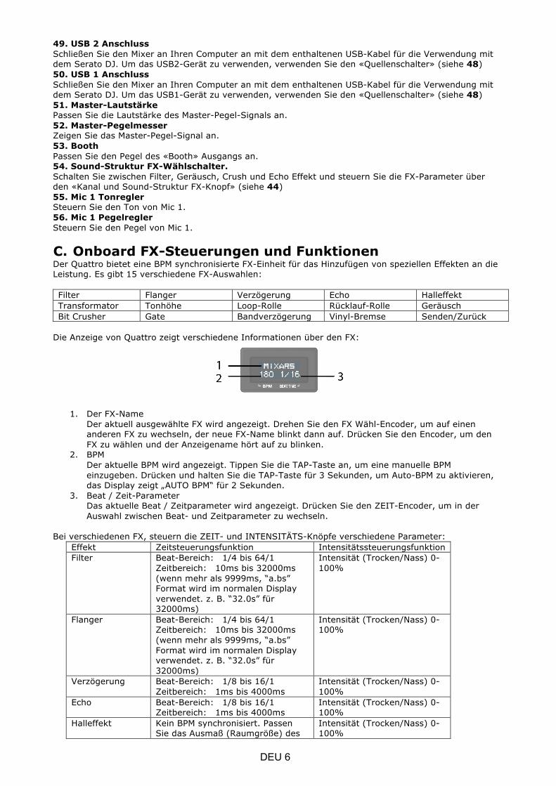
49. USB 2 Anschluss Schließen Sie den Mixer an Ihren Computer an mit dem enthaltenen USB-Kabel für die Verwendung mit dem Serato DJ. Um das USB2-Gerät zu verwenden, verwenden Sie den «Quellenschalter» (siehe 48) 50. USB 1 Anschluss Schließen Sie den Mixer an Ihren Computer an mit dem enthaltenen USB-Kabel für die Verwendung mit dem Serato DJ. Um das USB1-Gerät zu verwenden, verwenden Sie den «Quellenschalter» (siehe 48) 51. Master-Lautstärke Passen Sie die Lautstärke des Master-Pegel-Signals an. 52. Master-Pegelmesser Zeigen Sie das Master-Pegel-Signal an. 53. Booth Passen Sie den Pegel des «Booth» Ausgangs an. 54. Sound-Struktur FX-Wählschalter. Schalten Sie zwischen Filter, Geräusch, Crush und Echo Effekt und steuern Sie die FX-Parameter über den «Kanal und Sound-Struktur FX-Knopf» (siehe 44) 55. Mic 1 Tonregler Steuern Sie den Ton von Mic 1. 56. Mic 1 Pegelregler Steuern Sie den Pegel von Mic 1.
C. Onboard FX-Steuerungen und Funktionen Der Quattro bietet eine BPM synchronisierte FX-Einheit für das Hinzufügen von speziellen Effekten an die Leistung. Es gibt 15 verschiedene FX-Auswahlen: Filter Flanger Verzögerung Echo Halleffekt Transformator Tonhöhe Loop-Rolle Rücklauf-Rolle Geräusch Bit Crusher Gate Bandverzögerung Vinyl-Bremse Senden/Zurück
Die Anzeige von Quattro zeigt verschiedene Informationen über den FX:
1. Der FX-Name Der aktuell ausgewählte FX wird angezeigt. Drehen Sie den FX Wähl-Encoder, um auf einen anderen FX zu wechseln, der neue FX-Name blinkt dann auf. Drücken Sie den Encoder, um den FX zu wählen und der Anzeigename hört auf zu blinken.
2. BPM Der aktuelle BPM wird angezeigt. Tippen Sie die TAP-Taste an, um eine manuelle BPM einzugeben. Drücken und halten Sie die TAP-Taste für 3 Sekunden, um Auto-BPM zu aktivieren, das Display zeigt „AUTO BPM“ für 2 Sekunden.
3. Beat / Zeit-Parameter Das aktuelle Beat / Zeitparameter wird angezeigt. Drücken Sie den ZEIT-Encoder, um in der Auswahl zwischen Beat- und Zeitparameter zu wechseln.
Bei verschiedenen FX, steuern die ZEIT- und INTENSITÄTS-Knöpfe verschiedene Parameter:
Effekt Zeitsteuerungsfunktion Intensitätssteuerungsfunktion Filter Beat-Bereich: 1/4 bis 64/1
Zeitbereich: 10ms bis 32000ms (wenn mehr als 9999ms, “a.bs” Format wird im normalen Display verwendet. z. B. “32.0s” für 32000ms)
Intensität (Trocken/Nass) 0-100%
Flanger Beat-Bereich: 1/4 bis 64/1 Zeitbereich: 10ms bis 32000ms (wenn mehr als 9999ms, “a.bs” Format wird im normalen Display verwendet. z. B. “32.0s” für 32000ms)
Intensität (Trocken/Nass) 0-100%
Verzögerung Beat-Bereich: 1/8 bis 16/1 Zeitbereich: 1ms bis 4000ms
Intensität (Trocken/Nass) 0-100%
Echo Beat-Bereich: 1/8 bis 16/1 Zeitbereich: 1ms bis 4000ms
Intensität (Trocken/Nass) 0-100%
Halleffekt Kein BPM synchronisiert. Passen Sie das Ausmaß (Raumgröße) des
Intensität (Trocken/Nass) 0-100%
DEU 6

Halleffektes von 0% bis 100% an. Die Anzeige auf dem normalen Display sollte „0%“ bis „100%“ anzeigen. Die „Größe“ sollte auf dem Display als Titel angezeigt werden, wenn der Zeitknopf gedreht wird.
Transformator Beat-Bereich: 1/16 bis 16/1 Zeitbereich: 10ms bis 16000ms (wenn mehr als 9999ms, “a.bs” Format wird im normalen Display verwendet. z. B. “16.0s” für 16000ms)
Intensität (Trocken/Nass) 0-100%
Tonhöhe Kein BPM synchronisiert. Tonumfang von -50% bis 100%. „TONHÖHE“ wird als Titel angezeigt, wenn diese Parameter angepasst werden.
Befestigt 100% Nass
Loop-Rolle Beat-Bereich: 1/16 bis 16/1 Zeitbereich: 10ms bis 4000ms
Befestigt 100% Nass
Rücklauf-Rolle Beat-Bereich: 1/16 bis 16/1 Zeitbereich: 10ms bis 4000ms
Befestigt 100% Nass
Geräusch Beat-Bereich: 1/4 bis 64/1 Zeitbereich: 10ms bis 32000ms (wenn mehr als 9999ms, “a.bs” Format wird im normalen Display verwendet. z. B. “32.0s” für 32000ms)
Intensität (Trocken/Nass) 0-100%
Bit Crusher Kein BPM synchronisiert. Qualitätsparameterbereich von -100% bis 100%. „QUALITÄT“ wird auf dem Titel angezeigt, wenn diese Parameter angepasst werden
Intensität (Trocken/Nass) 0-100%
Gate Kein BPM synchronisiert. Schwellenwert-Anpassung aus den Schritten: Von 0% bis 100%
Intensität (Trocken/Nass) 0-100%
Bandverzögerung Kein BPM synchronisiert. Tonhöhe von Verzögerungssignalform -100% bis 100%.
Intensität (Trocken/Nass) 0-100%
Vinyl-Bremse Kein BPM synchronisiert. Pausenzeit von 10ms bis 4000ms.
Manuelle Steuerung des Pausen-FX. Im Uhrzeigersinn drehen, um die Pausenzeit zu aktivieren und zu verkürzen. Gegen den Uhrzeigersinn drehen, um unterbrochenen FX mit längerer Pausenzeit erneut zu aktivieren.
Senden/Zurück NA. Anzeige “---“ für Zeit/Beat-Feld Intensität (Trocken/Nass) 0-100%
DEU 7

D. Audio-Routing Es gibt 2 Audio-Routing Einstellungen in Quattro, nämlich das Serato-Routing und das nicht-Serato-Routing. Im Serato-Modus-Routing, funktioniert der Quattro als Steuerung und das meiste Mixen wird in der Serato DJ Software erledigt. Dies ermöglicht einen Post-Crossfader FX von Serato DJ. Das Serato-Modus Audio-Routing:
DEU 8
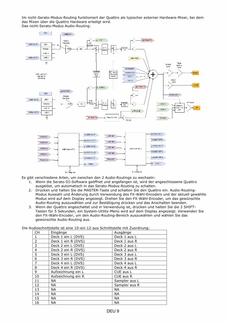
Im nicht-Serato-Modus-Routing funktioniert der Quattro als typischer externer Hardware-Mixer, bei dem das Mixen über die Quattro Hardware erledigt wird. Das nicht-Serato-Modus Audio-Routing:
Es gibt verschiedene Arten, um zwischen den 2 Audio-Routings zu wechseln:
1. Wenn die Serato-DJ-Software geöffnet und angefangen ist, wird der angeschlossene Quattro ausgelöst, um automatisch in das Serato-Modus-Routing zu schalten.
2. Drücken und halten Sie die MASTER-Taste und schalten Sie den Quattro ein. Audio-Routing-Modus Auswahl und Änderung durch Verwendung des FX-Wähl-Encoders und der aktuell gewählte Modus wird auf dem Display angezeigt. Drehen Sie den FX-Wähl-Encoder, um das gewünschte Audio-Routing auszuwählen und zur Bestätigung drücken und das Anschalten beenden.
3. Wenn der Quattro angeschaltet und in Verwendung ist, drücken und halten Sie die 2 SHIFT-Tasten für 5 Sekunden, ein System-Utility-Menü wird auf dem Display angezeigt. Verwenden Sie den FX-Wähl-Encoder, um den Audio-Routing-Bereich auszuwählen und wählen Sie das gewünschte Audio-Routing aus.
Die Audioschnittstelle ist eine 10-ein 12-aus Schnittstelle mit Zuordnung: CH Eingänge Ausgänge 1 Deck 1 ein L (DVS) Deck 1 aus L 2 Deck 1 ein R (DVS) Deck 1 aus R 3 Deck 2 ein L (DVS) Deck 2 aus L 4 Deck 2 ein R (DVS) Deck 2 aus R 5 Deck 3 ein L (DVS) Deck 3 aus L 6 Deck 3 ein R (DVS) Deck 3 aus R 7 Deck 4 ein L (DVS) Deck 4 aus L 8 Deck 4 ein R (DVS) Deck 4 aus R 9 Aufzeichnung ein L CUE aus L 10 Aufzeichnung ein R CUE aus R 11 NA Sampler aus L 12 NA Sampler aus R 13 NA NA 14 NA NA 15 NA NA 16 NA NA
DEU 9

E. System Utility-Menü Um in das System Utility-Menü zu gelangen, drücken und halten Sie die 2 SHIFT-Tasten, wenn Quattro arbeitet. Das Menü wird auf dem Display angezeigt. Verwenden Sie den FX-Wähl-Encoder, um auf verschiedene Optionen zu browsen und drücken Sie den Encoder, um die Einstellungen zu wählen und zu ändern: 1. Audio-Routing Wählen Sie zwischen Serato und nicht-Serato Audio-Routing 2. Crossfader-Leistung Wählen Sie zwischen der linearen und der angetriebenen Crossfader-Einstellung. Dies aktualisiert auch die Auswahl in der angeschlossenen Serato DJ-Software auf sowohl dem USB 1 als auch dem USB 2 Anschluss. 3. Firmware Version Anzeige der Firmware-Version. 4. Verlassen Sie das System Utility-Menü Drücken Sie den FX Wähl-Encoder, um das Utility-Menü zu verlassen.
F. Firmware-Update
Mixars verbessert kontinuierlich die Produkte und behebt Fehler durch die Herausgabe von neuer Firmware für die Produktion. Neue Firmware und Firmware-Update-Software-Tool können von der Mixars Webseite heruntergeladen werden (http://www.mixars.com). Firmware-Update-Vorgang: 1. Laden Sie das Firmware-Update-Tool und die neueste Firmware von der Mixars-Webseite
herunter. 2. Schließen Sie das USB-Kabel an den Computer an. 3. Drücken und halten Sie die FX CUE und TAP Taste und schalten Sie diese an. “FIRMWARE
UPDATE” wird auf dem Display angezeigt und der Quattro befindet sich im Firmware Update-Modus.
4. Öffnen Sie die Firmware-Update-Software und lokalisieren Sie die Firmware-Update-Datei. 5. Befolgen Sie die Anweisungen auf dem Bildschirm, um das Firmware-Update zu starten und
warten Sie auf die Eingabeaufforderung für die Beendung des Updates 6. Zyklus des Quattro nach Firmware-Update antreiben.
G. Spezifikationen 1. ALLGEMEINER BEREICH
Stromversorgung AC 100~240V 50Hz/60Hz Abmessungen 320(W) x 362(D) x 107(H) mm Verbrauch 20W Gewicht 5.35Kg
2. STANDARD TESTZUSTAND Umgebungstemperatur 23 +/- 2 degC Relative Feuchtigkeit 65% +/- 5% HINWEIS: Messungen können zwischen 5 GradC bis 35 GradC und 45% bis 85% relative Feuchtigkeit ausgeführt werden.
3. EINGANG / AUSGANG IMPEDANZ & SENSIBILITÄT: (1KHz,EQ FLACH, MAX. ZUNAHME) 3-1. EINGANG IMPEDANZ UND REFERENZ EINGANGSPEGEL:
LEITUNG: 47KΩ /-14dBV (200mV) PHONO: 47KΩ /-50dBV (3.16mV) MIC: 5KΩ/-54dBV (2mV) RÜCKLEITUNG: 47KΩ /-20dBV (100mV) USB -12dBFS
3-2. AUSGANG IMPEDANZ UND REFERENZ AUSGANGSPEGEL: MASTER(XLR): 600 OHM / 0dBV (1V) ± 2dB (Signal zu Signal 600 ohm) BOOTH: 600 OHM / 0dBV (1V) ± 2dB (Signal zu Signal 600 ohm) MASTER(RCA): 1K OHM / 0dBV (1V) ± 1dB (load=100K ohm) RECORD: 1K OHM / -9dBV (355mV) ± 1dB (load=100K ohm) SENDEN: 1K OHM / -14dBV (200mV) ± 1dB (load=100K ohm) PHONO: 32 OHM / -3dBV (708mV) ± 1dB (load=32 ohm)
DEU 10
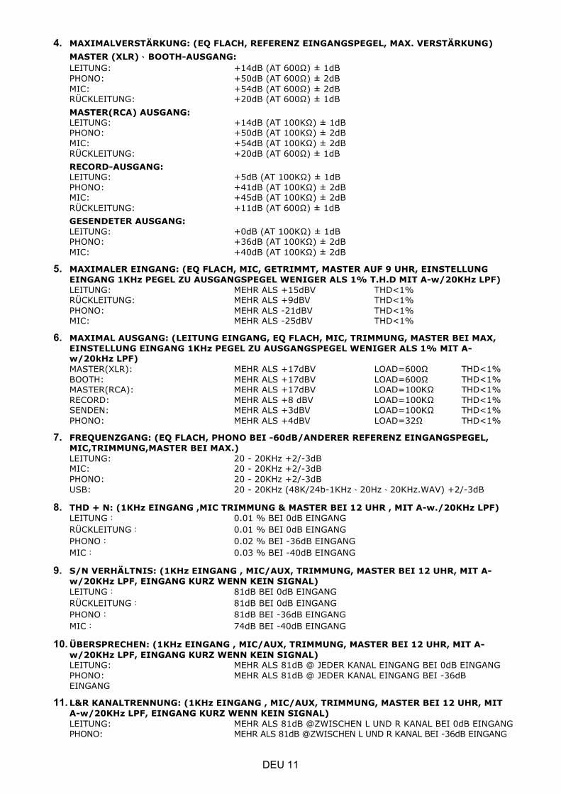
4. MAXIMALVERSTÄRKUNG: (EQ FLACH, REFERENZ EINGANGSPEGEL, MAX. VERSTÄRKUNG) MASTER (XLR)�BOOTH-AUSGANG: LEITUNG: +14dB (AT 600Ω) ± 1dB PHONO: +50dB (AT 600Ω) ± 2dB MIC: +54dB (AT 600Ω) ± 2dB RÜCKLEITUNG: +20dB (AT 600Ω) ± 1dB MASTER(RCA) AUSGANG: LEITUNG: +14dB (AT 100KΩ) ± 1dB PHONO: +50dB (AT 100KΩ) ± 2dB MIC: +54dB (AT 100KΩ) ± 2dB RÜCKLEITUNG: +20dB (AT 600Ω) ± 1dB RECORD-AUSGANG: LEITUNG: +5dB (AT 100KΩ) ± 1dB PHONO: +41dB (AT 100KΩ) ± 2dB MIC: +45dB (AT 100KΩ) ± 2dB RÜCKLEITUNG: +11dB (AT 600Ω) ± 1dB GESENDETER AUSGANG: LEITUNG: +0dB (AT 100KΩ) ± 1dB PHONO: +36dB (AT 100KΩ) ± 2dB MIC: +40dB (AT 100KΩ) ± 2dB
5. MAXIMALER EINGANG: (EQ FLACH, MIC, GETRIMMT, MASTER AUF 9 UHR, EINSTELLUNG EINGANG 1KHz PEGEL ZU AUSGANGSPEGEL WENIGER ALS 1% T.H.D MIT A-w/20KHz LPF) LEITUNG: MEHR ALS +15dBV THD<1% RÜCKLEITUNG: MEHR ALS +9dBV THD<1% PHONO: MEHR ALS -21dBV THD<1% MIC: MEHR ALS -25dBV THD<1%
6. MAXIMAL AUSGANG: (LEITUNG EINGANG, EQ FLACH, MIC, TRIMMUNG, MASTER BEI MAX, EINSTELLUNG EINGANG 1KHz PEGEL ZU AUSGANGSPEGEL WENIGER ALS 1% MIT A-w/20kHz LPF) MASTER(XLR): MEHR ALS +17dBV LOAD=600Ω THD<1% BOOTH: MEHR ALS +17dBV LOAD=600Ω THD<1% MASTER(RCA): MEHR ALS +17dBV LOAD=100KΩ THD<1% RECORD: MEHR ALS +8 dBV LOAD=100KΩ THD<1% SENDEN: MEHR ALS +3dBV LOAD=100KΩ THD<1% PHONO: MEHR ALS +4dBV LOAD=32Ω THD<1%
7. FREQUENZGANG: (EQ FLACH, PHONO BEI -60dB/ANDERER REFERENZ EINGANGSPEGEL, MIC,TRIMMUNG,MASTER BEI MAX.) LEITUNG: 20 - 20KHz +2/-3dB MIC: 20 - 20KHz +2/-3dB PHONO: 20 - 20KHz +2/-3dB USB: 20 - 20KHz (48K/24b-1KHz�20Hz�20KHz.WAV) +2/-3dB
8. THD + N: (1KHz EINGANG ,MIC TRIMMUNG & MASTER BEI 12 UHR , MIT A-w./20KHz LPF) LEITUNG� 0.01 % BEI 0dB EINGANG RÜCKLEITUNG� 0.01 % BEI 0dB EINGANG PHONO� 0.02 % BEI -36dB EINGANG MIC� 0.03 % BEI -40dB EINGANG
9. S/N VERHÄLTNIS: (1KHz EINGANG , MIC/AUX, TRIMMUNG, MASTER BEI 12 UHR, MIT A-w/20KHz LPF, EINGANG KURZ WENN KEIN SIGNAL) LEITUNG� 81dB BEI 0dB EINGANG RÜCKLEITUNG� 81dB BEI 0dB EINGANG PHONO� 81dB BEI -36dB EINGANG MIC� 74dB BEI -40dB EINGANG
10. ÜBERSPRECHEN: (1KHz EINGANG , MIC/AUX, TRIMMUNG, MASTER BEI 12 UHR, MIT A-w/20KHz LPF, EINGANG KURZ WENN KEIN SIGNAL) LEITUNG: MEHR ALS 81dB @ JEDER KANAL EINGANG BEI 0dB EINGANG PHONO: MEHR ALS 81dB @ JEDER KANAL EINGANG BEI -36dB EINGANG
11. L&R KANALTRENNUNG: (1KHz EINGANG , MIC/AUX, TRIMMUNG, MASTER BEI 12 UHR, MIT A-w/20KHz LPF, EINGANG KURZ WENN KEIN SIGNAL) LEITUNG: MEHR ALS 81dB @ZWISCHEN L UND R KANAL BEI 0dB EINGANG PHONO: MEHR ALS 81dB @ZWISCHEN L UND R KANAL BEI -36dB EINGANG
DEU 11
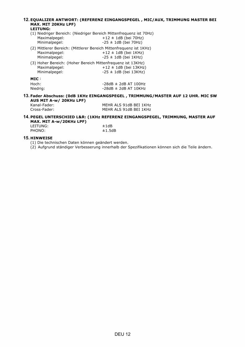
12. EQUALIZER ANTWORT: (REFERENZ EINGANGSPEGEL , MIC/AUX, TRIMMUNG MASTER BEI MAX. MIT 20KHz LPF) LEITUNG: (1) Niedriger Bereich: (Niedriger Bereich Mittenfrequenz ist 70Hz)
Maximalpegel: +12 ± 1dB (bei 70Hz) Minimalpegel: -25 ± 1dB (bei 70Hz)
(2) Mittlerer Bereich: (Mittlerer Bereich Mittenfrequenz ist 1KHz) Maximalpegel: +12 ± 1dB (bei 1KHz) Minimalpegel: -25 ± 1dB (bei 1KHz)
(3) Hoher Bereich: (Hoher Bereich Mittenfrequenz ist 13KHz) Maximalpegel: +12 ± 1dB (bei 13KHz) Minimalpegel: -25 ± 1dB (bei 13KHz)
MIC� Hoch: -28dB ± 2dB AT 100Hz Niedrig: -28dB ± 2dB AT 10KHz
13. Fader Abschuss: (0dB 1KHz EINGANGSPEGEL , TRIMMUNG/MASTER AUF 12 UHR. MIC SW AUS MIT A-w/ 20KHz LPF) Kanal-Fader: MEHR ALS 91dB BEI 1KHz Cross-Fader: MEHR ALS 91dB BEI 1KHz
14. PEGEL UNTERSCHIED L&R: (1KHz REFERENZ EINGANGSPEGEL, TRIMMUNG, MASTER AUF MAX. MIT A-w/20KHz LPF) LEITUNG: ±1dB PHONO: ±1.5dB
15. HINWEISE (1) Die technischen Daten können geändert werden. (2) Aufgrund ständiger Verbesserung innerhalb der Spezifikationen können sich die Teile ändern.
DEU 12


www.mixars.com