Embed Size (px)
Citation preview
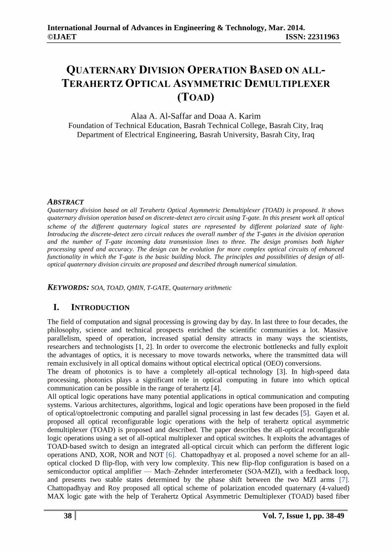
International Journal of Advances in Engineering & Technology, Mar. 2014.
©IJAET ISSN: 22311963
38 Vol. 7, Issue 1, pp. 38-49
QUATERNARY DIVISION OPERATION BASED ON ALL-
TERAHERTZ OPTICAL ASYMMETRIC DEMULTIPLEXER
(TOAD)
Alaa A. Al-Saffar and Doaa A. Karim Foundation of Technical Education, Basrah Technical College, Basrah City, Iraq
Department of Electrical Engineering, Basrah University, Basrah City, Iraq
ABSTRACT Quaternary division based on all Terahertz Optical Asymmetric Demultiplexer (TOAD) is proposed. It shows
quaternary division operation based on discrete-detect zero circuit using T-gate. In this present work all optical
scheme of the different quaternary logical states are represented by different polarized state of light.
Introducing the discrete-detect zero circuit reduces the overall number of the T-gates in the division operation
and the number of T-gate incoming data transmission lines to three. The design promises both higher
processing speed and accuracy. The design can be evolution for more complex optical circuits of enhanced
functionality in which the T-gate is the basic building block. The principles and possibilities of design of all-
optical quaternary division circuits are proposed and described through numerical simulation.
KEYWORDS: SOA, TOAD, QMIN, T-GATE, Quaternary arithmetic
I. INTRODUCTION
The field of computation and signal processing is growing day by day. In last three to four decades, the
philosophy, science and technical prospects enriched the scientific communities a lot. Massive
parallelism, speed of operation, increased spatial density attracts in many ways the scientists,
researchers and technologists [1, 2]. In order to overcome the electronic bottlenecks and fully exploit
the advantages of optics, it is necessary to move towards networks, where the transmitted data will
remain exclusively in all optical domains without optical electrical optical (OEO) conversions.
The dream of photonics is to have a completely all-optical technology [3]. In high-speed data
processing, photonics plays a significant role in optical computing in future into which optical
communication can be possible in the range of terahertz [4].
All optical logic operations have many potential applications in optical communication and computing
systems. Various architectures, algorithms, logical and logic operations have been proposed in the field
of optical/optoelectronic computing and parallel signal processing in last few decades [5]. Gayen et al.
proposed all optical reconfigurable logic operations with the help of terahertz optical asymmetric
demultiplexer (TOAD) is proposed and described. The paper describes the all-optical reconfigurable
logic operations using a set of all-optical multiplexer and optical switches. It exploits the advantages of
TOAD-based switch to design an integrated all-optical circuit which can perform the different logic
operations AND, XOR, NOR and NOT [6]. Chattopadhyay et al. proposed a novel scheme for an all-
optical clocked D flip-flop, with very low complexity. This new flip-flop configuration is based on a
semiconductor optical amplifier — Mach–Zehnder interferometer (SOA-MZI), with a feedback loop,
and presents two stable states determined by the phase shift between the two MZI arms [7].
Chattopadhyay and Roy proposed all optical scheme of polarization encoded quaternary (4-valued)
MAX logic gate with the help of Terahertz Optical Asymmetric Demultiplexer (TOAD) based fiber

International Journal of Advances in Engineering & Technology, Mar. 2014.
©IJAET ISSN: 22311963
39 Vol. 7, Issue 1, pp. 38-49
interferometric switch is described. For the quaternary information processing in optics, the quaternary
number (0, 1, 2, and 3) can be represented by four discrete polarized states of light [8]. Moniem and
Tanay proposed the implementation of binary decoder and encoder and using the optical hardware
components. All-optical circuits are implemented and designed with nonlinear material such as
terahertz optical asymmetric demultiplexer (TOAD) in optical tree architecture, polarization converters,
and optical circulator [9].
Among the proposed schemes, the terahertz optical asymmetric demultiplexer (TOAD) / semiconductor
optical amplifier (SOA)-assisted Sagnac gate effectively combines fast switching time and a reasonable
noise figure, with the ease of integration and overall practicality that enables it to compete favorably
with other similar optical time division multiplexing (OTDM) devices. TOAD is characterized by the
attractive features of fast switching time, high repetition rate, low power consumption, low latency,
noise and jitter tolerance, compactness, thermal stability and high nonlinear properties, which enable
their efficient exploitation in a real ultra-high speed optical communications environment [10]. TOAD
have the potential of being integrated, which in turn means that they can be repeatable and reliably
manufactured and massively produced so that they can be of commercial value and favorably compete
with other buffering solutions [11]. TOAD is operationally versatile, i.e. they can be exploited in more
complex all-optical signal processing applications without significantly changing their fundamental
architecture. In this communication we propose the TOAD-based switch to design an integrated all-
optical circuit which can perform different logical operations.
In this paper the quaternary division structure with detection circuit of zero number has been presented.
The structure of quaternary division based on (TOAD) used to design T-gate. Minimum number of T-
gates is used to set the design. The paper is organized as follows. In Section II principle and operation
of TOAD based optical switch is discussed. Section 3.1 and section 3.2 describe the design and
operational principle of some basic all-optical quaternary logic circuits (QMIN, Delta Literal). Section
3.3 describes the principle of T-gate and its operation. Section IV discuss detect-zero circuit and its
operational principle. Section V describes quaternary division operation with discrete detect zero
circuit. Section VI discusses simulation results and discussion. Section VII discusses conclusion and
suggests a roadmap for future works.
II. SOA-ASSISTED SAGANAC SWITCH ̸ TOAD BASED ALL-OPTICAL SWITCH
Quaternary logic (R =4) has four logical states {0, 1, 2, 3}. In optics, the quaternary number has been
represented by four discrete polarized state of light. In optical implementation we can consider the set
of quaternary logic states {0, 1, 2, 3}:
0 = no light,
1 = vertically polarized light (↕),
2 = horizontally polarized light (●) and
3 = partially polarized light ( ).
Like binary world there are also numbers of basic gates in multi-valued logic world. Depending on the
radix and number of variables used, different logic functions can be generated. The numbers of possible
functions are [12]. ( )( , ) (1)
nRf R n R
Where R is the radix and n is the number of variables, in quaternary logic (R=4) of two variables (n=2),
there are 24(4,2) 4f = 4294967296 possible functions. Among the proposed schemes, TOAD / SOA-
assisted Sagnac gate effectively combines fast switching time and a reasonable noise figure, with the
ease of integration and overall practicality that enables it to compete favorably with other similar optical
time division multiplexing (OTDM) devices [13].
TOAD are characterized by the attractive features of fast switching time, high repetition rate, low
power consumption, low latency, noise and jitter tolerance, compactness, thermal stability and high
nonlinear properties, which enable their efficient exploitation in a real ultra-high speed optical
communications environment. TOAD have the potential of being integrated, which in turn means that
they can be repeatable and reliable manufactured and massively produced so that they can be of
International Journal of Advances in Engineering & Technology, Mar. 2014.
©IJAET ISSN: 22311963
40 Vol. 7, Issue 1, pp. 38-49
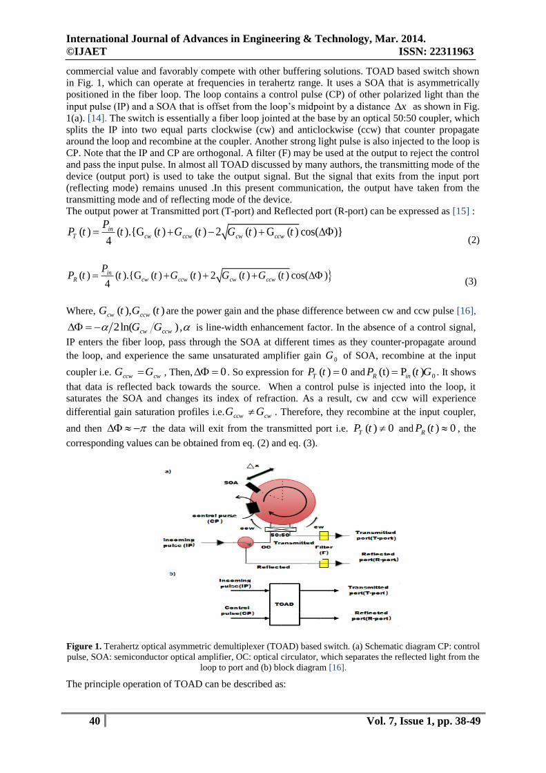
commercial value and favorably compete with other buffering solutions. TOAD based switch shown
in Fig. 1, which can operate at frequencies in terahertz range. It uses a SOA that is asymmetrically
positioned in the fiber loop. The loop contains a control pulse (CP) of other polarized light than the
input pulse (IP) and a SOA that is offset from the loop’s midpoint by a distance x as shown in Fig.
1(a). [14]. The switch is essentially a fiber loop jointed at the base by an optical 50:50 coupler, which
splits the IP into two equal parts clockwise (cw) and anticlockwise (ccw) that counter propagate
around the loop and recombine at the coupler. Another strong light pulse is also injected to the loop is
CP. Note that the IP and CP are orthogonal. A filter (F) may be used at the output to reject the control
and pass the input pulse. In almost all TOAD discussed by many authors, the transmitting mode of the
device (output port) is used to take the output signal. But the signal that exits from the input port
(reflecting mode) remains unused .In this present communication, the output have taken from the
transmitting mode and of reflecting mode of the device.
The output power at Transmitted port (T-port) and Reflected port (R-port) can be expressed as [15] :
( ) ( ).{G ( ) ( ) 2 ( ) G ( ) cos( )}4
inT cw ccw cw ccw
PP t t t G t G t t
(2)
( ) ( ).{G ( ) ( ) 2 ( ) ( ) cos( )4
inR cw ccw cw ccw
PP t t t G t G t G t
(3)
Where, ( ), ( )cw ccwG t G t are the power gain and the phase difference between cw and ccw pulse [16],
2ln( ),cw ccwG G is line-width enhancement factor. In the absence of a control signal,
IP enters the fiber loop, pass through the SOA at different times as they counter-propagate around
the loop, and experience the same unsaturated amplifier gain 0G of SOA, recombine at the input
coupler i.e. ccw cwG G , Then, 0 . So expression for ( ) 0TP t and 0(t) P ( )R inP t G . It shows
that data is reflected back towards the source. When a control pulse is injected into the loop, it
saturates the SOA and changes its index of refraction. As a result, cw and ccw will experience
differential gain saturation profiles i.e. ccw cwG G . Therefore, they recombine at the input coupler,
and then the data will exit from the transmitted port i.e. ( ) 0TP t and ( ) 0RP t , the
corresponding values can be obtained from eq. (2) and eq. (3).
Figure 1. Terahertz optical asymmetric demultiplexer (TOAD) based switch. (a) Schematic diagram CP: control
pulse, SOA: semiconductor optical amplifier, OC: optical circulator, which separates the reflected light from the
loop to port and (b) block diagram [16].
The principle operation of TOAD can be described as:
International Journal of Advances in Engineering & Technology, Mar. 2014.
©IJAET ISSN: 22311963
41 Vol. 7, Issue 1, pp. 38-49
Case1: CP=ON, then SOA changes its index of refraction. As a result, cw and ccw will experience a
differential gain saturation profiles. Therefore, cross phase modulation (XPM) takes place when they
recombine at the input coupler. Then, relative phase difference between cw and ccw pulses becomes
and the data will exit from the transmitted port (T-port) according to Fig.1.
Case 2: CP=OFF, cw and ccw enter the fiber loop, pass through the SOA at different times counter-
propagate around the loop, it experience the nearly same unsaturated amplifier gain of SOA, and then
they recombine at the input coupler. Relative phase difference between cw and ccw is zero (0), and no
data is found at the T-port. Then data is reflected back toward the source and isolated by optical
circulator (OC) [17].Table-1 describe the operation of TOAD.
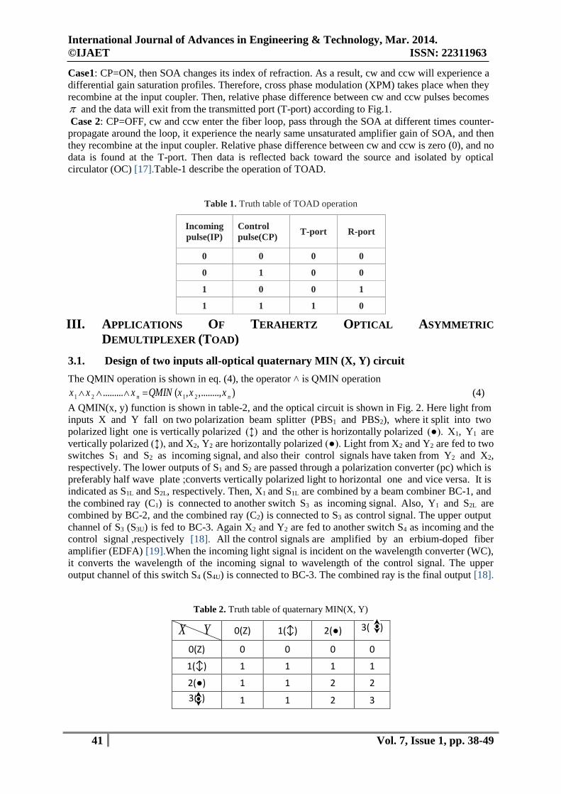
Table 1. Truth table of TOAD operation
Incoming
pulse(IP)
Control
pulse(CP) T-port R-port
0 0 0 0
0 1 0 0
1 0 0 1
1 1 1 0
III. APPLICATIONS OF TERAHERTZ OPTICAL ASYMMETRIC
DEMULTIPLEXER (TOAD)
3.1. Design of two inputs all-optical quaternary MIN (X, Y) circuit
The QMIN operation is shown in eq. (4), the operator ˄ is QMIN operation
1 2 1 2......... ( , ,........, )n nx x x QMIN x x x (4)
A QMIN(x, y) function is shown in table-2, and the optical circuit is shown in Fig. 2. Here light from
inputs X and Y fall on two polarization beam splitter (PBS1 and PBS2), where it split into two
polarized light one is vertically polarized (↕) and the other is horizontally polarized (●). X1, Y1 are
vertically polarized (↕), and X2, Y2 are horizontally polarized (●). Light from X2 and Y2 are fed to two
switches S1 and S2 as incoming signal, and also their control signals have taken from Y2 and X2,
respectively. The lower outputs of S1 and S2 are passed through a polarization converter (pc) which is
preferably half wave plate ;converts vertically polarized light to horizontal one and vice versa. It is
indicated as S1L and S2L, respectively. Then, X1 and S1L are combined by a beam combiner BC-1, and
the combined ray (C1) is connected to another switch S3 as incoming signal. Also, Y1 and S2L are
combined by BC-2, and the combined ray (C2) is connected to S3 as control signal. The upper output
channel of S3 (S3U) is fed to BC-3. Again X2 and Y2 are fed to another switch S4 as incoming and the
control signal ,respectively [18]. All the control signals are amplified by an erbium-doped fiber
amplifier (EDFA) [19].When the incoming light signal is incident on the wavelength converter (WC),
it converts the wavelength of the incoming signal to wavelength of the control signal. The upper
output channel of this switch S4 (S4U) is connected to BC-3. The combined ray is the final output [18].
Table 2. Truth table of quaternary MIN(X, Y)
X Y 0(Z) 1(↕) 2(●) 3( ))
0(Z) 0 0 0 0
1(↕) 1 1 1 1
2(●) 1 1 2 2
3( ) 1 1 2 3

International Journal of Advances in Engineering & Technology, Mar. 2014.
©IJAET ISSN: 22311963
42 Vol. 7, Issue 1, pp. 38-49
The operational principle of quaternary minimum is illustrated as:
CASE 1: X=0, X1=X2=0, if Y=0; Y1=Y2=0 then S1L=C1=S2L=C2=S3U=S4U=O/P=0. Therefore, for
different values of Y<123> the output is 0 (no light).
CASE 2: X=1, X1=1, X2=0, if Y=0; Y1=Y2=0 then, C1=1, S1L=C2=S2L=S3U=S4U=O/P=0. For different
values of Y<123>, the output is 1 (vertical polarized light).
CASE 3: X=2, X1=0, X2=2, if Y=0; Y1=Y2=0 then, SIL=C1=2, S2L=C2=S3U=S4U=O/P=0. For values of
Y<23>, the output is 2 (horizontal polarized light) but if the value of Y is 1 then, the output is 1
(vertical polarized light).
CASE 4: X=3, X1=1, X2=2, if Y=0; Y1=Y2=0 then, S2L=C2=S3U=S4U=0, S1L=2, C1=3 and the output is
0. For the different values of Y <123> the output equals to the value of Y.
Figure 2. All-optical quaternary QMIN(X, Y) circuit. S: switch, NOLM: Non-linear optical loop mirror,
PBS: polarizing beam Splitter, BC: beam Combiner, PC: polarization converter, ► EDFA: erbium doped fiber
amplifier, ■ wavelength converter [18].
3.2. Design of all optical quaternary Delta Literal circuit
Literals are very important function in multi-valued logic based information processing. The truth
table of Delta literal circuit is in the table- 4 and the circuit diagram is shown in the Fig. 3. Here, X is
the quaternary input, which can take any one of the four quaternary logic states <0123> and the
outputs are x 0, x 1, x 2 and x 3, respectively [4].
Table 3. Truth table of quaternary Delta Literals
X O/P X3 X2 X1 X0
0 (z) 0 0 0 3
1(↕) 0 0 3 0
2(●) 0 3 0 0
3( ) 3 0 0 0
International Journal of Advances in Engineering & Technology, Mar. 2014.
©IJAET ISSN: 22311963
43 Vol. 7, Issue 1, pp. 38-49
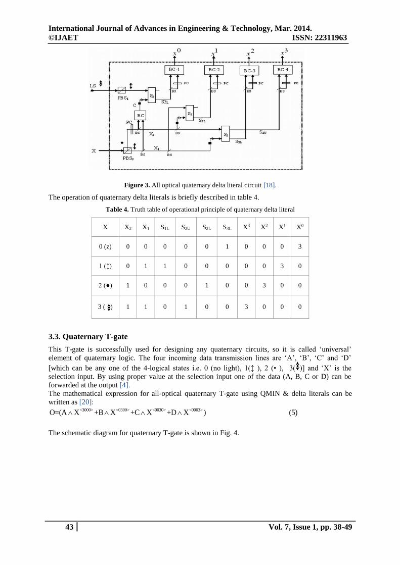
Figure 3. All optical quaternary delta literal circuit [18].
The operation of quaternary delta literals is briefly described in table 4.
Table 4. Truth table of operational principle of quaternary delta literal
X X2 X1 S1L S2U S2L S3L X3 X2 X1 X0
0 (z) 0 0 0 0 0 1 0 0 0 3
1 (↕) 0 1 1 0 0 0 0 0 3 0
2 (●) 1 0 0 0 1 0 0 3 0 0
3 ( ) 1 1 0 1 0 0 3 0 0 0
3.3. Quaternary T-gate
This T-gate is successfully used for designing any quaternary circuits, so it is called ‘universal’
element of quaternary logic. The four incoming data transmission lines are ‘A’, ‘B’, ‘C’ and ‘D’
[which can be any one of the 4-logical states i.e. 0 (no light), 1(↕ ), 2 (• ), 3( )] and ‘X’ is the
selection input. By using proper value at the selection input one of the data (A, B, C or D) can be
forwarded at the output [4].
The mathematical expression for all-optical quaternary T-gate using QMIN & delta literals can be
written as [20]: <3000> <0300> <0030> <0003>O=(A X +B X +C X +D X ) (5)
The schematic diagram for quaternary T-gate is shown in Fig. 4.
International Journal of Advances in Engineering & Technology, Mar. 2014.
©IJAET ISSN: 22311963
44 Vol. 7, Issue 1, pp. 38-49
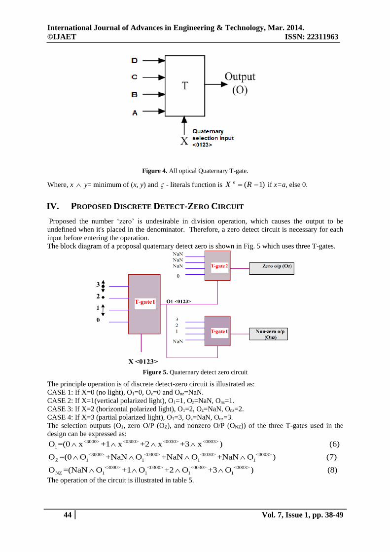
Figure 4. All optical Quaternary T-gate.
Where, x y= minimum of (x, y) and - literals function is ( 1)aX R if x=a, else 0.
IV. PROPOSED DISCRETE DETECT-ZERO CIRCUIT
Proposed the number ‘zero’ is undesirable in division operation, which causes the output to be
undefined when it's placed in the denominator. Therefore, a zero detect circuit is necessary for each
input before entering the operation.
The block diagram of a proposal quaternary detect zero is shown in Fig. 5 which uses three T-gates.
Figure 5. Quaternary detect zero circuit
The principle operation is of discrete detect-zero circuit is illustrated as:
CASE 1: If X=0 (no light), O1=0, Oz=0 and Onz=NaN.
CASE 2: If X=1(vertical polarized light), O1=1, Oz=NaN, Onz=1.
CASE 3: If X=2 (horizontal polarized light), O1=2, Oz=NaN, Onz=2.
CASE 4: If X=3 (partial polarized light), O1=3, Oz=NaN, Onz=3.
The selection outputs (O1, zero O/P (OZ), and nonzero O/P (ONZ)) of the three T-gates used in the
design can be expressed as: <3000> <0300> <0030> <0003>
1
<3000> <0300> <0030> <0003>
Z 1 1 1 1
<3000> <0300> <0030> <0003>
NZ 1 1 1 1
O =(0 x +1 x +2 x +3 x ) (6)
O =(0 O +NaN O +NaN O +NaN O ) (7)
O =(NaN O +1 O +2 O +3 O ) (8)
The operation of the circuit is illustrated in table 5.
International Journal of Advances in Engineering & Technology, Mar. 2014.
©IJAET ISSN: 22311963
45 Vol. 7, Issue 1, pp. 38-49
Table 5. Truth table of discrete detect zero circuit
x O1 OZ ONZ
0 0 0 NaN
1 1 NaN 1
2 2 NaN 2
3 3 NaN 3
V. PROPOSED QUATERNARY DIVISION OPERATION WITH DISCRETE
DETECT ZERO CIRCUIT
The quaternary division is intricacy operation and cannot implement when the zero number found in
denominator because the result is undefined, so the discrete detect-zero circuit provides the possibility
of implemented division operation.
Conventional safe quaternary division operation is implemented without getting NaN result. It’s T-
gate has four incoming data transmission lines (A, B, C, D) and one selection input [20]. Proposed the
discrete detect zero circuit provided the possibility to reduce the number of incoming data
transmission lines to three (A, B, C) therefore, reducing the storage memory, less number of optical
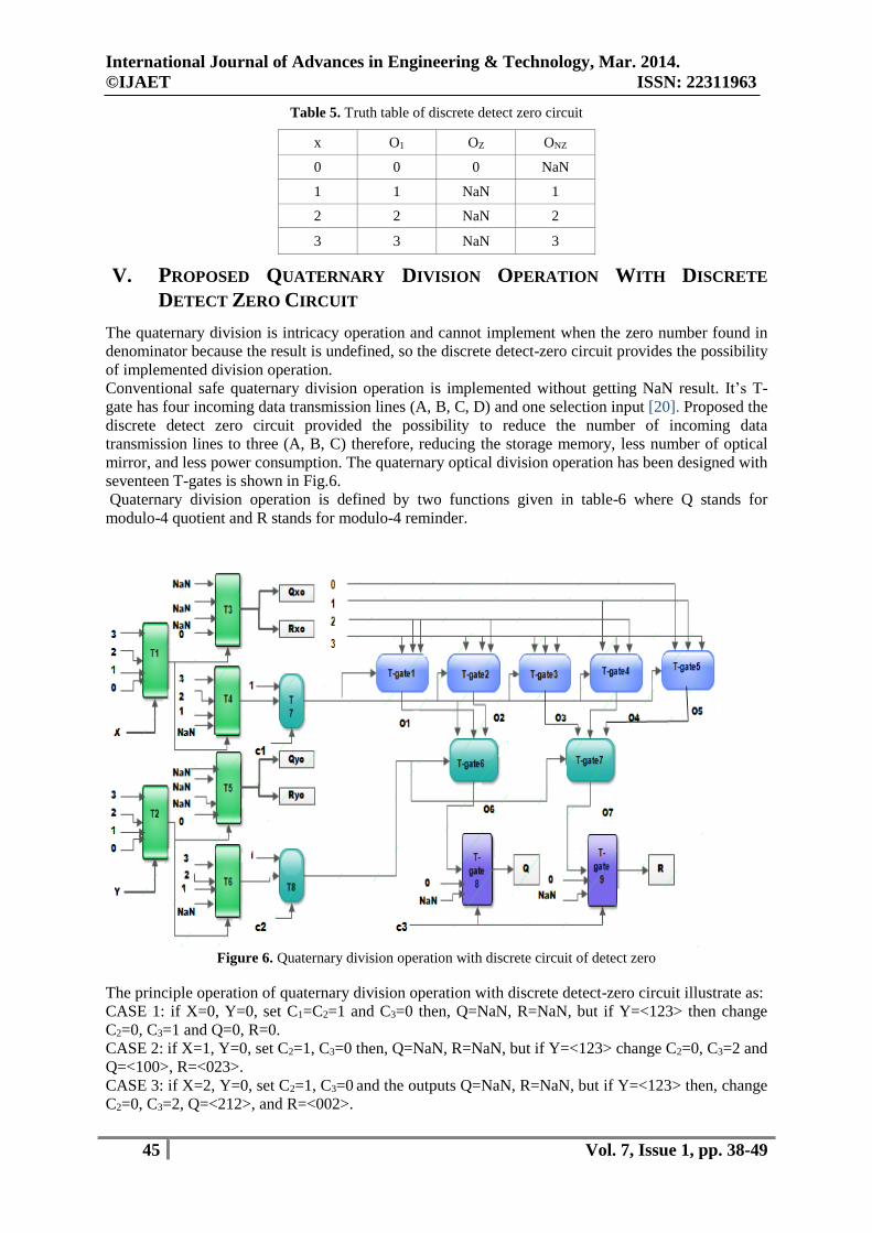
mirror, and less power consumption. The quaternary optical division operation has been designed with
seventeen T-gates is shown in Fig.6.
Quaternary division operation is defined by two functions given in table-6 where Q stands for
modulo-4 quotient and R stands for modulo-4 reminder.
Figure 6. Quaternary division operation with discrete circuit of detect zero
The principle operation of quaternary division operation with discrete detect-zero circuit illustrate as:
CASE 1: if X=0, Y=0, set C1=C2=1 and C3=0 then, Q=NaN, R=NaN, but if Y=<123> then change
C2=0, C3=1 and Q=0, R=0.
CASE 2: if X=1, Y=0, set C2=1, C3=0 then, Q=NaN, R=NaN, but if Y=<123> change C2=0, C3=2 and
Q=<100>, R=<023>.
CASE 3: if X=2, Y=0, set C2=1, C3=0 and the outputs Q=NaN, R=NaN, but if Y=<123> then, change
C2=0, C3=2, Q=<212>, and R=<002>.

International Journal of Advances in Engineering & Technology, Mar. 2014.
©IJAET ISSN: 22311963
46 Vol. 7, Issue 1, pp. 38-49
CASE 4: if X=3,Y=0, set C2=1, C3=0 then, Q=NaN, R=NaN, but if Y=<123> then, C2=0, C3=2,
Q=<311>, and R=<010>.
Note that NaN refer to not a number, Most operations propagate NaN without signaling exceptions,
and signal the invalid operation exception when given a signaling NaN operand [21].
Table 6. Truth table of quaternary division i) quotient (Q) and ii) reminder (R)
The mathematical expressions according to Fig.6 are: <300> <030> <003>
1
<300> <030> <003>
2
<300> <030> <003>
3
<300> <030> <003>
4
<300> <030> <003>
5
<300> <030>
6 1 2
O =(0 x +1 x +1 x ) (9)
O =(0 x +0 x +1 x ) (10)
O =(0 x +0 x +0 x ) (11)
O =(2 x +0 x +1 x ) (12)
O =(3 x +2 x +0 x ) (13)
O =(x y +O y +O
<003>
<300> <030> <003>
7 3 4 5
y ) (14)
O =(O y +O y +O y ) (15)
The output equations of the quaternary division design can be expressed as: <300> <030> <003>
6 3 3 3
<300> <030> <003>
7 3 3 3
Q=(O C +NaN C +0 C ) (16)
R=(O C +NaN C +0 C ) (17)
VI. RESULTS AND DISCUSSION
Result of numerical simulation of TOAD based detect zero circuit with MATLAB is shown in Fig. 7.
In simulation, signal X = {0, 1, 2, 3}. The pulse shape is Gaussian in nature. It is clear from the results
that the output is NaN in Onz if X or Y input is zero and the output Oz is equal to zero as shown in fig.
7a, but if input is not equal to zero then, Oz is NaN and Onz is equal value of X or Y as shown in fig.
7b.
-10 0 10 20 30 40 50 60 70-1
-0.5
0
0.5
1THE INPUT X
X
-10 0 10 20 30 40 50 60 70-1
-0.5
0
0.5
1THE OUTPUT Oz
Oz
-10 0 10 20 30 40 50 60 700
0.2
0.4
0.6
0.8
1THE OUTPUT Onz
Onz
(a)
X/Y 1 2 3
i)quotient(Q)
1 (↕) 1 0 0
2 (●) 2 1 0
3( ) 3 1 1
ii)Reminder(R)
1 (↕) 0 2 3
2 (●) 0 0 2
3 ( ) 0 1 0

International Journal of Advances in Engineering & Technology, Mar. 2014.
©IJAET ISSN: 22311963
47 Vol. 7, Issue 1, pp. 38-49
-10 0 10 20 30 40 50 60 700
0.5
1
1.5
2THE INPUT X
X
-10 0 10 20 30 40 50 60 700
0.2
0.4
0.6
0.8
1THE OUTPUT Oz
Oz
-10 0 10 20 30 40 50 60 700
0.5
1
1.5
2THE OUTPUT Onz
Onz
no light
vertical lght
horizontal light
partial light
(b)
Figure 7. Simulated waveforms of detect zero operation
(a) X=0, Oz=0, Onz=NaN
(b) X=2, Oz=NaN, Onz=2
Figure 8 shows the simulation results of the quaternary division operation using discrete detect-zero
for the inputs X=<0123> and Y=<0123>. Simulation results for two cases are presented. In case the
inputs are X=0 and Y=0, the outputs are Q=NaN and R=NaN, sea Fig. 8a. while for the inputs X=3
and Y=2, the outputs are (Q=1 and R=1) as shown in fig. 8b. Numerical simulation results verify the
theoretical results.
-10 0 10 20 30 40 50 60 70-1
-0.5
0
0.5
1THE INPUT X
X
-10 0 10 20 30 40 50 60 70-1
-0.5
0
0.5
1THE INPUT Y
Y
-10 0 10 20 30 40 50 60 700
0.2
0.4
0.6
0.8
1THE OUTPUT Q
Q
-10 0 10 20 30 40 50 60 700
0.2
0.4
0.6
0.8
1THE OUTPUT R
R
(a)

International Journal of Advances in Engineering & Technology, Mar. 2014.
©IJAET ISSN: 22311963
48 Vol. 7, Issue 1, pp. 38-49
-10 0 10 20 30 40 50 60 700
0.5
1
1.5
2
2.5
3THE INPUT X
X
-10 0 10 20 30 40 50 60 700
0.5
1
1.5
2THE INPUT Y
Y
-10 0 10 20 30 40 50 60 700
0.2
0.4
0.6
0.8
1THE OUTPUT Q
Q
-10 0 10 20 30 40 50 60 700
0.2
0.4
0.6
0.8
1THE OUTPUT R
R
(b)
Figure 8. Simulated waveforms of quaternary division operation
(a) X=0, Y=0,Q=NaN, R=NaN
(b) X=3, Y=2,Q=1, R=1
VII. CONCLUSION AND FUTURE WORK
A design for quaternary division operation is presented in this paper. The design is based on discrete
detect zero circuit. The significant advantage of this proposed scheme is that the logical operations,
which can be performed, are all-optical in nature The conventional design of T-gate used four
incoming data transmission lines and one selection input but using the proposal discrete detect zero
design reducing number of incoming data transmission lines to three. Laser of wavelength 1552 and
1534 nm can be used as input/control signal, respectively. The design of discrete detect zero circuit
introduced new horizons for the basic arithmetic operation to reduce the number of T-gates and the
number of incoming data transmission lines. For the future work the proposed design for detect zero
can be easily and successfully extended to get a compact design of detect-zero circuit into which only
one circuit is used. The scheme can also be improved by removing the controls in the quaternary
division design led to reduction of the number of T-gates.
REFERENCES
[1]. Nabil H. Farhat, “Photonic Neural Networks and Learning Machines”, IEEE EXPERT, University of
Pennsylvania, (Oct. 1992).
[2]. P. Bruce Berra, , Arif Ghafoor, Mohsen Guizani, Slawomir J. MarcInkowski, and Pericles A. Mitkas,
"Optics and Supercomputing ”, IEEE, Vol. 77, No.12, (Dec. 1989).
[3]. Bing C. Wang, Varghese Baby, Wilson Tong, Lei Xu, Michelle Friedman, Robert J.Runser, Ivan Glesk,
and Paul R. Prucnal, "A novel fast optical switch based on two cascaded Terahertz Optical Asymmetric
Demultiplexers (TOAD) ”, Dept. of Electrical Engineering, Princeton University OPTICS EXPRESS 15, Vol.
10, No. 1, 14 Jan. (2002).
[4]. Jitendra Nath Roy and Tanay Chattopadhyay, "All-Optical Quaternary Logic Based Information
Processing: Challenges and Opportunities", licensee InTech, (2013).
[5]. Dilip Kumar Gayen, Jitendra Nath Roy, Chinmoy Taraphdar, and Rajat Kumar Pal, “All-optical
reconfigurable logic operations with the help of terahertz optical asymmetric demultiplexer”, Optik, Vol. 122,
pp. 711-718, (2010).
[6]. Dilip Kumar Gayen, Jitendra Nath Roy,Chinmoy Taraphdar, Rajat Kumar Pal, “All-optical reconfigurable
logic operations with the help of terahertz opticalasymmetric demultiplexer”, optic, vol. 122 , pp. 711–718,
(2011).

International Journal of Advances in Engineering & Technology, Mar. 2014.
©IJAET ISSN: 22311963
49 Vol. 7, Issue 1, pp. 38-49
[7]. Tanay Chattopadhyay, Cláudia Reis, Paulo André, António Teixeira, “Theoretical analysis of all-optical
clocked D flip-flop using a single SOA assisted symmetric MZI”, Optics Communications, vol. 285, pp. 2266–
2275, (2012).
[8]. TanayChattopadhyay, JitendraNathRoy, ” Design of polarization encoded all-optical 4-valued MAX logic
gate and its applications”, Optics Communications, vol. 300, pp. 119–128, (2013).
[9]. Tamer. A. Moniem, Tanay C, “ALL OPTICAL BINARY DECODER AND ENCODER USING THE
TERAHERTZ OPTICAL ASYMMETRIC DEMULTIPLEXER (TOAD)”, Minia Journal of Engineering and
Technology, Vol. 32, No.1, ( Jan. 2013).
[10]. Kristian E. Stubkjaer, " Semiconductor Optical Amplifier-Based All-Optical Gates for High-Speed Optical
Processing", IEEE JOURNAL ON SELECTED TOPICS IN QUANTUM ELECTRONICS, Vol. 6, No. 6,
Nov./Dec. 2000.
[11]. V. M. Menon, W. Tong, C. Li, F. Xia, I. Glesk, P. R. Prucnal and S. R. Forrest, ," All-Optical Wavelength
Conversion Using a Regrowth-Free Monolithically Integrated Sagnac Interferometer", IEEE PHOTONICS
TECHNOLOGY LETTERS, Vol. 15, No. 2, Feb. 2003.
[12]. Ricardo Cunha, Henri Boudinov and Luigi Carro, “Quaternary Look-up Tables Using Voltage-Mode
CMOS Logic Design", Brazil, IEEE, 2007.
[13]. Dilip Kumar Gayen , Tanay Chattopadhyay, Rajat Kumar Pal, and Jitendra Nath Roy, " All-optical pretix
tree adder with the help of terahertz optical asymmetric demultiplexer", CHINES OPTICS LETTERS, COL
9(6), Jun. 10, 2011.
[14]. Tanay Chattopadhyay and Jitendra Nath Roy, “Polarization encoded TOAD based all-optical quaternary
literals", Optik, Vol. 121, pp. 617–622, 2010.
[15]. Tanay Chattopadhyay and Jitendra Nath Roy, “Design of polarization encoded all-optical 4-valued MAX
logic gate and its applications", Optics Communications, Vol. 300, PP. 119–128, 2013.
[16]. M. Eiselt, W. Pieper, and H. G. Weber, " SLALOM: Semiconductor Laser Amplifier in a Loop Mirror",
JOURNAL OF LIGHTWAVE TECHNOLOGY, Vol. 13, No. 10, Oct. 1995.
[17]. Tanay Chattopadhyay and Jitendra Nath Roy, “Polarization encoded all-optical quaternary successor with
the help of SOA assisted Sagnac switch", Optics Communications, Vol. 284, pp. 2755–2762, 2011.
[18]. Tanay Chattopadhyay and Jitendra Nath Roy, "Polarization-encoded all-optical quaternary multiplexer and
demultiplexer – A proposal", Optik, Vol. 120, PP. 941–946, 2009.
[19]. Jyoti Gujral and Vishu Goel, “Analysis of Augmented Gain EDFA Systems using Single and Multi-
wavelength Sources", International Journal of Computer Applications, Vol. 47, No. 4, Jun. 2012.
[20]. Tanay Chattopadhyay, “All-optical quaternary circuits using quaternary T-gate", Optik, Vol. 121, pp.
1784–1788, 2010.
[21]. Microprocessor Standards Committee, “IEEE Standard for Floating-Arithmetic", New York, USA, IEEE,
29 Aug. 2008
AUTHORS
Alaa A. Al-Saffar was born in Basrah, Iraq, in 1957. He received the B.Sc, M.Sc and PHD
from the University of Basarh, College of Engineering, Electrical Engineering Department
in 1979, 1982 and 2001, respectively. His current research interests include optical
computing and robotic control.
Doaa A. Karim was born in Basrah, Iraq, in 1990. She received the B.Sc from the
University of Basrah, College of Engineering, Computer Engineering Department in
2011.Currently she is master student in University of Basrah, College of Engineering,
Electrical Engineering Department.