Embed Size (px)
Citation preview
ISO 9001:2015
Certified
No part of the document may be circulated, quoted, or reproduced for distribution without prior written approval from
Quasonix, Inc.
Copyright Quasonix, Inc., All Rights Reserved.
Quasonix Binary Protocol for Transmitters
Version 1.009 04/02/2019
Quasonix, Inc.
6025 Schumacher Park Dr.
West Chester, OH 45069
02 February, 2021
Revision 4.0.3
Specifications subject to change without notice.
All Quasonix transmitter products are under U.S. Department of Commerce jurisdiction categorized as EAR99; not covered by ITAR.

Transmitter Binary Communications
i Quasonix, Inc.
Table of Contents
1 Binary Transmitter Serial Protocol ......................................................................................................... 1
1.1 Binary Serial Protocol .................................................................................................................. 1
1.1.1 Binary Protocol Packet Definition ............................................................................................ 1
1.1.2 Binary Packet Errors ............................................................................................................... 2
1.1.3 Sending and Receiving Multiple TLV Commands ................................................................... 2
1.2 Information Response Tags......................................................................................................... 3
1.2.1 BP NAK: Tag 0x0001 .............................................................................................................. 3
1.2.2 BP NAK Bad ID: Tag 0x0002 .................................................................................................. 3
1.2.3 BP ACK: Tag 0x0003 .............................................................................................................. 3
1.2.4 BP Unknown TAG: Tag 0x0004 .............................................................................................. 3
1.2.5 BP Invalid TAG: Tag 0x0005 ................................................................................................... 3
1.2.6 BP Invalid TAG Data: Tag 0x0006 .......................................................................................... 3
1.2.7 BP Missing Option: Tag 0x0008 .............................................................................................. 4
2 Transmitter Save and Recall Command Tag Definitions ....................................................................... 5
2.1 BP Save Command: Tag 0x5000 ................................................................................................ 5
2.2 BP Recall Command: Tag 0x5100 .............................................................................................. 5
3 Transmitter Set Command Tag Definitions............................................................................................ 6
3.1 Set Commands ............................................................................................................................ 6
3.1.1 BP Set Mode: Tag 0x5001 ...................................................................................................... 6
3.1.2 BP Set Clock-free Bit Rate: Tag 0x5002 ................................................................................. 6
3.1.3 BP Set Data Polarity: Tag 0x5003........................................................................................... 6
3.1.4 BP Set Clock Polarity: Tag 0x5004 ......................................................................................... 7
3.1.5 BP Set Frequency: Tag 0x5005 .............................................................................................. 7
3.1.6 BP Set Randomizer On: Tag 0x5506 ...................................................................................... 7
3.1.7 BP Set Differential Encoding: Tag 0x5007 .............................................................................. 7
3.1.8 BP Set RF On: Tag 0x5008 ..................................................................................................... 8
Transmitter Binary Communications
ii Quasonix, Inc.
3.1.9 BP Set Clock Source: Tag 0x5009 .......................................................................................... 8
3.1.10 BP Set Internal Clock: Tag 0x500A ......................................................................................... 8
3.1.11 BP Set Data Source: Tag 0x500B ........................................................................................... 8
3.1.12 BP Set Internal Data: Tag 0x500C .......................................................................................... 9
3.1.13 BP Set Frequency Step: Tag 0x500D ..................................................................................... 9
3.1.14 BP Set Variable Power New: Tag 0x500F ............................................................................ 10
3.1.15 BP Set High Power Level: Tag 0x5010 ................................................................................. 10
3.1.16 BP Set Low Power Level: Tag 0x5011 .................................................................................. 10
3.1.17 BP Set Low Density Parity Check State: Tag 0x5012........................................................... 10
3.1.18 BP Set Convolutional Encoding State: Tag 0x5013 .............................................................. 11
3.1.19 BP Set NRZ-M Encoding State: Tag 0x5014 ........................................................................ 11
3.1.20 BP Set Channel Delay Enable State: Tag 0x5015 ................................................................ 11
3.1.21 BP Set Channel Delay Value: Tag 0x5016 ........................................................................... 11
3.1.22 BP Set Modulation Scaling Value: Tag 0x5017 .................................................................... 12
3.1.23 BP Set Automatic Carrier Output Enable: Tag 0x5250 ......................................................... 12
3.1.24 BP Set Clock Free Disable: Tag 0x5251 ............................................................................... 12
3.1.25 BP Set RF On/Off Pin Polarity State: Tag 0x5252 ................................................................ 12
3.1.26 BP Set Overtemperature Control State: Tag 0x5253 ............................................................ 12
3.1.27 BP Set ASCII Passthrough Enable: Tag 0x5254 .................................................................. 13
3.1.28 BP Set Dual Transmitter Channel: Tag 0x5400 .................................................................... 13
3.1.29 BP Send ASCII Passthrough Message: Tag 0x5401 ............................................................ 13
3.1.30 BP ASCII Passthrough Message: Tag 0x5402 ..................................................................... 13
3.2 Set Command Summary ........................................................................................................... 15
4 Transmitter Get Command Tag Definitions ......................................................................................... 17
4.1 Get Commands .......................................................................................................................... 17
4.1.1 BP Get Binary Protocol Version: Tag 0x4000 ....................................................................... 17
4.1.2 BP Get Device Model Number: Tag 0x4001 ......................................................................... 17
Transmitter Binary Communications
iii Quasonix, Inc.
4.1.3 BP Get Device Serial Number: Tag 0x4002 .......................................................................... 17
4.1.4 BP Get Software Version: Tag 0x4003 ................................................................................. 17
4.1.5 BP Get FPGA Version: Tag 0x4004 ...................................................................................... 18
4.1.6 BP Get Available Modes: Tag 0x4100 .................................................................................. 18
4.1.7 BP Get Bit Rate Range: Tag 0x4101 .................................................................................... 19
4.1.8 BP Get Frequency Bands: Tag 0x4104 ................................................................................ 19
4.1.9 BP Get L Band Range: Tag 0x4105 ...................................................................................... 20
4.1.10 BP Get U Band Range: Tag 0x4106 ..................................................................................... 20
4.1.11 BP Get M Band Range: Tag 0x4107 ..................................................................................... 20
4.1.12 BP Get LS Band Range: Tag 0x4108 ................................................................................... 21
4.1.13 BP Get US Band Range: Tag 0x4109 ................................................................................... 21
4.1.14 BP Get C Band Range: Tag 0x410A ..................................................................................... 21
4.1.15 BP Get MC Band Range: Tag 0x410B .................................................................................. 21
4.1.16 BP Get EX Band Range: Tag 0x410C .................................................................................. 22
4.1.17 BP Get Mode: Tag 0x4201 .................................................................................................... 22
4.1.18 BP Get Clock Free Bit Rate: Tag 0x4202 ............................................................................. 23
4.1.19 BP Get Data Polarity: Tag 0x4203 ........................................................................................ 23
4.1.20 BP Get Clock Polarity: Tag 0x4204 ....................................................................................... 23
4.1.21 BP Get Frequency: Tag 0x4205 ............................................................................................ 24
4.1.22 BP Get Randomizer On: Tag 0x4206 ................................................................................... 24
4.1.23 BP Get Differential Encoding: Tag 0x4207 ........................................................................... 24
4.1.24 BP Get RF State: Tag 0x4208 ............................................................................................... 24
4.1.25 BP Get Clock Source: Tag 0x4209 ....................................................................................... 25
4.1.26 BP Get Internal Clock: Tag 0x420A ...................................................................................... 25
4.1.27 BP Get Data Source: Tag 0x420B ........................................................................................ 25
4.1.28 BP Get Internal Data: Tag 0x420C........................................................................................ 25
4.1.29 BP Get Frequency Step: Tag 0x420D ................................................................................... 26
Transmitter Binary Communications
iv Quasonix, Inc.
4.1.30 BP Get Variable Power New: Tag 0x420F ............................................................................ 27
4.1.31 BP Get High Power Level: Tag 0x4210 ................................................................................ 27
4.1.32 BP Get Low Power Level: Tag 0x4211 ................................................................................. 27
4.1.33 BP Get LDPC State: Tag 0x4212 .......................................................................................... 27
4.1.34 BP Get Convolutional Encoding State: Tag 0x4213 ............................................................. 28
4.1.35 BP Get NRZ-M Encoding State: Tag 0x4214 ........................................................................ 28
4.1.36 BP Get Channel Delay Enable State: Tag 0x4215 ............................................................... 28
4.1.37 BP Get Channel Delay Value: Tag 0x4216 ........................................................................... 29
4.1.38 BP Get Modulation Scaling Value: Tag 0x4217 .................................................................... 29
4.1.39 BP Get Automatic Carrier Output Enable: Tag 0x4250......................................................... 29
4.1.40 BP Get Clock Free Disable: Tag 0x4251 .............................................................................. 29
4.1.41 BP Get RF On/Off Pin Polarity State: Tag 0x4252 ................................................................ 30
4.1.42 BP Get Overtemperature Control State: Tag 0x4253 ........................................................... 30
4.1.43 BP Get ASCII Passthrough Enable: Tag 0x4254 .................................................................. 30
4.1.44 BP Get Temperature: Tag 0x4300 ........................................................................................ 30
4.1.45 BP Get Status 1: Tag 0x4301 ................................................................................................ 31
4.1.46 BP Get Detected Bit Rate: Tag 0x4302 ................................................................................ 32
4.1.47 BP Get PA Drain Voltage and Current: Tag 0x4303 ............................................................. 33
4.1.48 BP Get DTX Channel: Tag 0x4400 ....................................................................................... 33
4.2 Get Command Summary ........................................................................................................... 33
5 Proposed New Binary Protocol Tags ................................................................................................... 36
6 Appendix A – Legacy Binary Transmitter Serial Protocol .................................................................... 37
6.1 Legacy Binary Serial Protocol ................................................................................................... 37
6.1.1 Legacy Packet Format Definition .......................................................................................... 37
6.1.2 Legacy Binary Packet Formation .......................................................................................... 37
6.1.3 Receiving a Legacy Binary Packet from the Device ............................................................. 38
6.1.4 Legacy Binary Packet Errors ................................................................................................. 38
Transmitter Binary Communications
v Quasonix, Inc.
6.1.5 Legacy TLV Commands - Payload Data ............................................................................... 38
6.1.5.1 Legacy TLV Data Information ........................................................................................... 38
6.1.6 Legacy Set and Get Command Operations .......................................................................... 39
6.1.6.1 Legacy SET Command ..................................................................................................... 39
6.1.6.2 Legacy GET Command .................................................................................................... 39
6.1.7 Handshake Events ................................................................................................................ 39
6.1.8 Sending and Receiving Multiple Legacy TLV Commands .................................................... 39
6.1.9 Legacy Binary Packet Formation Samples ........................................................................... 39
6.2 Legacy Information Response Tags .......................................................................................... 41
6.2.1 NAK: Tag 0x0001 .................................................................................................................. 41
6.2.2 NAK Bad ID: Tag 0x0002 ...................................................................................................... 41
6.2.3 ACK: Tag 0x0003 .................................................................................................................. 41
6.2.4 Unknown TAG: Tag 0x0004 .................................................................................................. 41
6.2.5 Invalid TAG: Tag 0x0005 ....................................................................................................... 41
6.2.6 Invalid TAG Data: Tag 0x0006 .............................................................................................. 41
6.2.7 Tag Limit Exceeded: Tag 0x0007.......................................................................................... 41
6.3 Legacy Transmitter Set Command Tag Definitions ................................................................... 42
6.3.1 TX Set Mode: Tag 0x0010 .................................................................................................... 42
6.3.2 TX Set Data Polarity: Tag 0x0012 ......................................................................................... 42
6.3.3 TX Set Clock Polarity: Tag 0x0013 ....................................................................................... 42
6.3.4 TX Set Frequency: Tag 0x0017 ............................................................................................ 42
6.3.5 TX Set Randomizer: Tag 0x2015 .......................................................................................... 43
6.3.6 TX Set Differential Encoding: Tag 0x0019 ............................................................................ 43
6.3.7 TX Set RF On: Tag 0x2018 ................................................................................................... 43
6.3.8 TX Set Clock Source: Tag 0x2019 ........................................................................................ 43
6.3.9 TX Set Internal Clock: Tag 0x201A ....................................................................................... 43
6.3.10 TX Set Data Source: Tag 0x201B ......................................................................................... 43
6.3.11 TX Set Internal Data: Tag 0x201C ........................................................................................ 44
Transmitter Binary Communications
vi Quasonix, Inc.
6.3.12 TX Set Variable Power: Tag 0x201D .................................................................................... 44
6.3.13 TX Set Variable Power New: Tag 0x201E ............................................................................ 44
6.3.14 TX Save Command: Tag 0x0040 .......................................................................................... 44
6.4 Legacy Set Command Summary ............................................................................................... 44
6.5 Legacy Transmitter Get Command Tag Definitions .................................................................. 45
6.5.1 TX Get Mode: Tag 0x0090 .................................................................................................... 46
6.5.2 TX_Get Data Polarity: Tag 0x0092 ....................................................................................... 46
6.5.3 TX_Get Clock Polarity: Tag 0x0093 ...................................................................................... 46
6.5.4 TX Get Frequency: Tag 0x0097 ............................................................................................ 46
6.5.5 TX Get Randomizer: Tag 0x2095.......................................................................................... 47
6.5.6 TX Get RF On: Tag 0x2098 .................................................................................................. 47
6.5.7 TX Get Differential Encoding: Tag 0x0099 ............................................................................ 47
6.5.8 TX Get Clock Source: Tag 0x2099........................................................................................ 47
6.5.9 TX Get Internal Clock: Tag 0x209A ...................................................................................... 47
6.5.10 TX Get Data Source: Tag 0x209B......................................................................................... 47
6.5.11 TX Get Internal Data: Tag 0x209C ........................................................................................ 48
6.5.12 TX Get Temperature: Tag 0x009A ........................................................................................ 48
6.5.13 TX Get Variable Power: Tag 0x221D .................................................................................... 48
6.5.14 TX Get Variable Power New: Tag 0x221E ............................................................................ 48
6.5.15 TX Get Device Serial Number: Tag 0x0101 .......................................................................... 48
6.5.16 TX Get Available Modes: Tag 0x0102 .................................................................................. 48
6.5.17 TX Get Software Version: Tag 0x0107 ................................................................................. 49
6.5.18 TX Get FPGA Version: Tag 0x0109 ...................................................................................... 49
6.5.19 TX Get Variable Power Available: Tag 0x2202 ..................................................................... 49
6.5.20 TX Get New Variable Power Available: Tag 0x0206............................................................. 49
6.5.21 TX Get Differential Encoding Available: Tag 0x0202 ............................................................ 50
6.5.22 TX Get Internal Clock Maximum: Tag 0x209E ...................................................................... 50
Transmitter Binary Communications
vii Quasonix, Inc.
6.5.23 TX Get Internal Clock Minimum: Tag 0x209F ....................................................................... 50
6.5.24 TX Get Available Bands: Tag 0x0205 ................................................................................... 50
6.5.25 TX Get Configuration Status: Tag 0x2107 ............................................................................ 51
6.5.26 TX Get Power Status: Tag 0x2108........................................................................................ 51
6.5.27 Get Frequency Bands: Tag 0x0210 ...................................................................................... 52
6.5.28 Get Frequency Band S Maximum: Tag 0x0211 .................................................................... 52
6.5.29 Get Frequency Band S Minimum: Tag 0x0212 ..................................................................... 52
6.5.30 Get Frequency Band L Maximum: Tag 0x0213 .................................................................... 52
6.5.31 Get Frequency Band L Minimum: Tag 0x0214 ..................................................................... 52
6.5.32 Get Frequency Band U Maximum: Tag 0x0215 .................................................................... 53
6.5.33 Get Frequency Band U Minimum: Tag 0x0216 ..................................................................... 53
6.5.34 Get Frequency Band C Maximum: Tag 0x021A ................................................................... 53
6.5.35 Get Frequency Band C Minimum: Tag 0x022B .................................................................... 53
6.5.36 Get Frequency Band P Maximum: Tag 0x022C ................................................................... 53
6.5.37 Get Frequency Band P Minimum: Tag 0x022D .................................................................... 54
6.5.38 Get Frequency Band Mid-C Maximum: Tag 0x022E ............................................................ 54
6.5.39 Get Frequency Band Mid-C Minimum: Tag 0x022F .............................................................. 54
6.6 Legacy Get Command Summary .............................................................................................. 54
6.7 Legacy Transmitter GET, SET, and Response Codes .............................................................. 57
6.8 Device Types ............................................................................................................................. 59
7 Appendix B – Acronym List .................................................................................................................. 60
List of Figures
Figure 1: Status 1 Message Bits Example .................................................................................................. 32
Figure 2: Legacy Binary Packet Example ................................................................................................... 37
Transmitter Binary Communications
viii Quasonix, Inc.
List of Tables
Table 1: Packet Format ................................................................................................................................. 1
Table 2: Binary Packet Example, Set Clock Source to Internal .................................................................... 2
Table 3: Transmitter Save/Recall Commands .............................................................................................. 5
Table 4: Set Mode Descriptions .................................................................................................................... 6
Table 5: Dual TX ........................................................................................................................................... 9
Table 6: Single TX ......................................................................................................................................... 9
Table 7: LDPC Codes ................................................................................................................................. 10
Table 8: Transmitter Information Responses .............................................................................................. 15
Table 9: Transmitter SET Commands ........................................................................................................ 15
Table 10: BP Get Available Modes Bit Definitions ...................................................................................... 18
Table 11: BP Get Frequency Bands Bit Descriptions ................................................................................. 19
Table 12: Quasonix TX Mode Descriptions ................................................................................................ 22
Table 13: Dual TX ....................................................................................................................................... 26
Table 14: Single TX ..................................................................................................................................... 26
Table 15: LDPC Codes ............................................................................................................................... 27
Table 16: Transmitter Information Responses ............................................................................................ 33
Table 17: Transmitter GET Commands ...................................................................................................... 34
Table 18: Proposed Transmitter GET/SET Commands ............................................................................. 36
Table 18: Packet Format ............................................................................................................................. 37
Table 19: Binary Packet Example, Single TLV with Clock Invert................................................................ 39
Table 20: Binary Packet Example, Single TLV, Multiple Bytes as ASCII Data ........................................... 40
Table 21: Example - Setting SOQPSK 0x00 0x02 ..................................................................................... 42
Table 22: Legacy Transmitter Information Responses ............................................................................... 44
Table 23: Legacy Transmitter SET Commands .......................................................................................... 45
Table 24: TX Get Mode Bit Descriptions ..................................................................................................... 46
Table 25: TX Get Available Modes Bit Descriptions ................................................................................... 49
Table 26: TX Get Available Bands Bit Descriptions .................................................................................... 50
Table 27: Get Configuration Status Format ................................................................................................ 51
Table 28: Get Power Status Format ........................................................................................................... 51
Table 29: Legacy Transmitter Information Responses ............................................................................... 54
Table 30: Legacy Transmitter GET Commands ......................................................................................... 55
Table 31: Legacy Transmitter Information Responses ............................................................................... 57
Table 32: Legacy Transmitter SET Commands .......................................................................................... 57
Table 33: Legacy Transmitter GET Commands ......................................................................................... 58

Transmitter Binary Communications
ix Quasonix, Inc.
Transmitter Binary Communications
1 Quasonix, Inc.
1 Binary Transmitter Serial Protocol
1.1 Binary Serial Protocol
The binary serial protocol is designed to facilitate efficient machine to machine communication. The following
defines the binary protocol version 1.009. Legacy binary protocol information is located in Appendix A – Legacy
Binary Transmitter Serial Protocol.
Note: There is no released manual for binary protocol version 1.006 or 1.007. Version 1.006 is the same as 1.007
except for the following additions for 1.007: ASCII pass through Enable GET/SET, with the associated messages,
and the BP_GET_DRAIN_V_AND_I message to read the PA drain voltage and current, where possible. Version
1.008 adds a well defined ACK for Set commands.
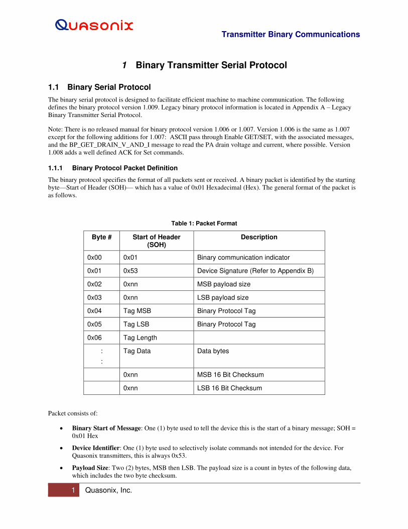
1.1.1 Binary Protocol Packet Definition
The binary protocol specifies the format of all packets sent or received. A binary packet is identified by the starting
byte—Start of Header (SOH)— which has a value of 0x01 Hexadecimal (Hex). The general format of the packet is
as follows.
Table 1: Packet Format
Byte # Start of Header (SOH)
Description
0x00 0x01 Binary communication indicator
0x01 0x53 Device Signature (Refer to Appendix B)
0x02 0xnn MSB payload size
0x03 0xnn LSB payload size
0x04 Tag MSB Binary Protocol Tag
0x05 Tag LSB Binary Protocol Tag
0x06 Tag Length
:
:
Tag Data Data bytes
0xnn MSB 16 Bit Checksum
0xnn LSB 16 Bit Checksum
Packet consists of:
• Binary Start of Message: One (1) byte used to tell the device this is the start of a binary message; SOH =
0x01 Hex
• Device Identifier: One (1) byte used to selectively isolate commands not intended for the device. For
Quasonix transmitters, this is always 0x53.
• Payload Size: Two (2) bytes, MSB then LSB. The payload size is a count in bytes of the following data,
which includes the two byte checksum.
Transmitter Binary Communications
2 Quasonix, Inc.
• Tag - Tag consists of two bytes and forms the command
• Tag Length - Length is one byte. The length indicates how many bytes will be used for the Tag data, with
a maximum size of 255 bytes.
• Tag Data - Data is the tag specific data, 0-255 bytes.
Tag, Tag Length, and Tag Data may have multiple occurrences
• Checksum: The binary protocol uses a two (2) byte checksum. The checksum is calculated by adding each
byte of the Payload Data. When calculating the Payload Checksum in software, an unsigned 16 bit variable
should be used. This allows for the rollover of the variable when the calculation exceeds its maximum
0xFFFF value.
Note: This calculation includes everything after the payload length bytes, except the final two bytes which
ARE this checksum.
1.1.2 Binary Packet Errors
Errors that are detected by the protocol are Timeout, Bad Checksum, Bad Tag, Bad Tag Data, etc.
Communication with the device is done on a master / slave basis. The transmitter is the slave to any requests sent to
it. After sending a binary packet to the transmitter, a binary packet response should always be received. Not
receiving a response after an expected time period constitutes a communications timeout and possible loss of
connection from the device. This timeout may be caused by incorrect serial communications settings and/or cabling
problems. It is up to the master (system requesting data from the device) to handle any timeout conditions.
1.1.3 Sending and Receiving Multiple TLV Commands
Multiple tags can be sent together in one packet, as shown in the previous sections. The transmitter response
contains corresponding tag responses. Single tags are generally simpler to work with.
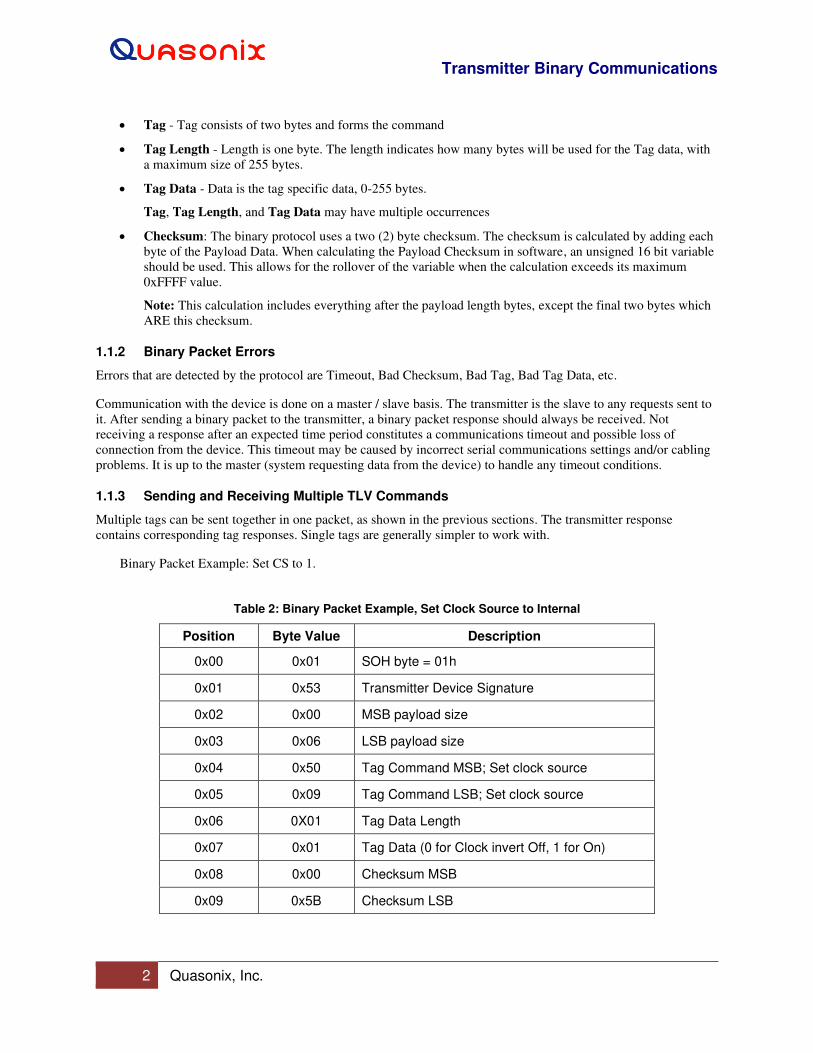
Binary Packet Example: Set CS to 1.
Table 2: Binary Packet Example, Set Clock Source to Internal
Position Byte Value Description
0x00 0x01 SOH byte = 01h
0x01 0x53 Transmitter Device Signature
0x02 0x00 MSB payload size
0x03 0x06 LSB payload size
0x04 0x50 Tag Command MSB; Set clock source
0x05 0x09 Tag Command LSB; Set clock source
0x06 0X01 Tag Data Length
0x07 0x01 Tag Data (0 for Clock invert Off, 1 for On)
0x08 0x00 Checksum MSB
0x09 0x5B Checksum LSB

Transmitter Binary Communications
3 Quasonix, Inc.
1.2 Information Response Tags
1.2.1 BP NAK: Tag 0x0001
The BP_NAK tag response indicates that the device received a corrupt message or timed out. The received tags
could not be processed by the device. This message has a zero tag data length.
Example: Checksum should be 00 44, but transmitter received 00 43
Sent BP Message: 01 53 00 05 44 00 00 00 43 (force bad checksum to see error)
Received BP Message: 01 53 00 05 00 01 00 00 01
1.2.2 BP NAK Bad ID: Tag 0x0002
The BP_NAK_BAD_ID response indicates that the device ID does not match the transmitter ID. The message is
ignored and NAK Bad ID is returned. This message has a zero tag data length.
Example:
Sent BP Message: 01 54 00 05 44 00 00 00 44
Received BP Message: 01 53 00 05 00 02 00 00 02
1.2.3 BP ACK: Tag 0x0003
The BP_ACK response is not currently in use.
1.2.4 BP Unknown TAG: Tag 0x0004
The BP_UNKNOWN_TAG response indicates that the device received an unknown tag. Older devices may not
support the given tag and this response will be returned. If more than one tag was sent to the device, then the
remaining tags will be processed. This message has a zero tag data length.
Example:
Sent BP Message: 01 53 00 05 FF 00 01 FE
Received BP Message: 01 53 00 05 00 04 00 00 04
1.2.5 BP Invalid TAG: Tag 0x0005
The BP_INVALID_TAG response indicates that the device understood the tag but found that it was not valid for the
active mode or device itself. This is the response to a command tag which is not allowed, but is known, such as DE
in PCM/FM mode. This message has a zero tag data length.
1.2.6 BP Invalid TAG Data: Tag 0x0006
The BP_INVALID_TAG_DATA response indicates that the device understood the tag but found that the data was
not valid for the given tag. This message has a zero tag data length. For example, command CS expects a 0 or 1. If
the data is 7, this is bad tag data.
Example:
Sent BP Message: 01 53 00 06 50 09 01 07 01 61
Received BP Message: 01 53 00 05 00 06 00 00 06
Transmitter Binary Communications
4 Quasonix, Inc.
1.2.7 BP Missing Option: Tag 0x0008
The BP_MISSING_OPTION response indicates that the tag requires an option that the transmitter does not have.
Example: Tried to send a SET CF (clock free) command with no CF option on the transmitter
Sent BP Message: 01 53 00 06 52 51 01 01 00 A5
Received BP Message: 01 53 00 05 00 08 00 00 08

Transmitter Binary Communications
5 Quasonix, Inc.
2 Transmitter Save and Recall Command Tag Definitions
2.1 BP Save Command: Tag 0x5000
Tag BP_SAVE_CMD takes a one byte preset number to save the configuration setup. Quasonix transmitters have 16
save profile settings. Preset 0 is used for the default startup configuration.
Valid range is 0-15
Example: Save setup to preset 4
Sent Message: 01 53 00 06 50 00 01 04 00 55
Received Message: 01 53 00 06 50 00 01 04 00
2.2 BP Recall Command: Tag 0x5100
Tag BP_RECALL_CMD response has a one byte recall location. Transmitter devices have up to 15 recall profile
settings. Save profile 0 is used to save the profile that the device configures to after a power cycle.
Value range is 0-15
Example: Recall setup profile 13
(Get Message) Sent Message: 01 53 00 06 51 00 01 0D 00 5F
(Get Response) Received Message: 01 53 00 06 51 00 01 0D 00 5F
Setup Profile = 13
Table 3: Transmitter Save/Recall Commands
Command Protocol Defines
Description
BP_SAVE_CMD 0x5000 1 byte save location (0-15)
BP_RECALL_CMD 0x5100 1 byte recall location (0-15)
Transmitter Binary Communications
6 Quasonix, Inc.
3 Transmitter Set Command Tag Definitions
3.1 Set Commands
This section provides all of the tag definitions for the transmitter Set commands.
The set command acknowledgement is defined as the set command tag with a tag length of 1 and a data value of 0
for success, or a non-zero value if there was any error that did NOT cause an error tag to replace the set tag.
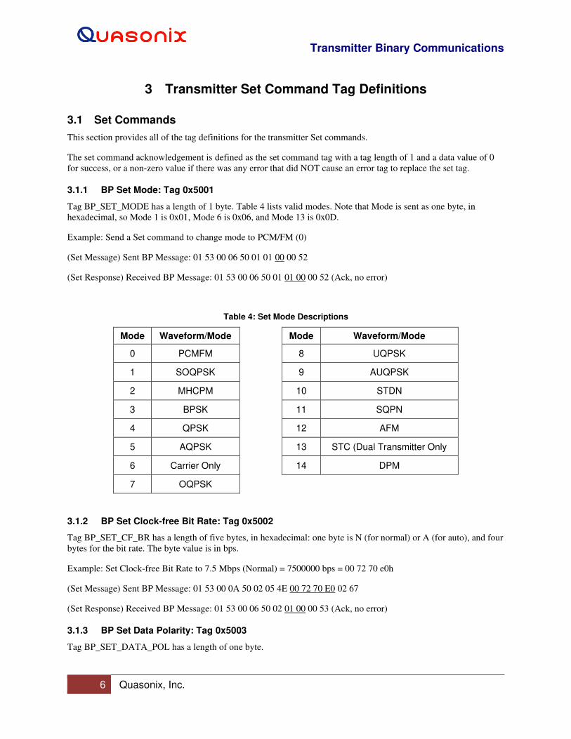
3.1.1 BP Set Mode: Tag 0x5001
Tag BP_SET_MODE has a length of 1 byte. Table 4 lists valid modes. Note that Mode is sent as one byte, in
hexadecimal, so Mode 1 is 0x01, Mode 6 is 0x06, and Mode 13 is 0x0D.
Example: Send a Set command to change mode to PCM/FM (0)
(Set Message) Sent BP Message: 01 53 00 06 50 01 01 00 00 52
(Set Response) Received BP Message: 01 53 00 06 50 01 01 00 00 52 (Ack, no error)
Table 4: Set Mode Descriptions
Mode Waveform/Mode Mode Waveform/Mode
0 PCMFM 8 UQPSK
1 SOQPSK 9 AUQPSK
2 MHCPM 10 STDN
3 BPSK 11 SQPN
4 QPSK 12 AFM
5 AQPSK 13 STC (Dual Transmitter Only
6 Carrier Only 14 DPM
7 OQPSK
3.1.2 BP Set Clock-free Bit Rate: Tag 0x5002
Tag BP_SET_CF_BR has a length of five bytes, in hexadecimal: one byte is N (for normal) or A (for auto), and four
bytes for the bit rate. The byte value is in bps.
Example: Set Clock-free Bit Rate to 7.5 Mbps (Normal) = 7500000 bps = 00 72 70 e0h
(Set Message) Sent BP Message: 01 53 00 0A 50 02 05 4E 00 72 70 E0 02 67
(Set Response) Received BP Message: 01 53 00 06 50 02 01 00 00 53 (Ack, no error)
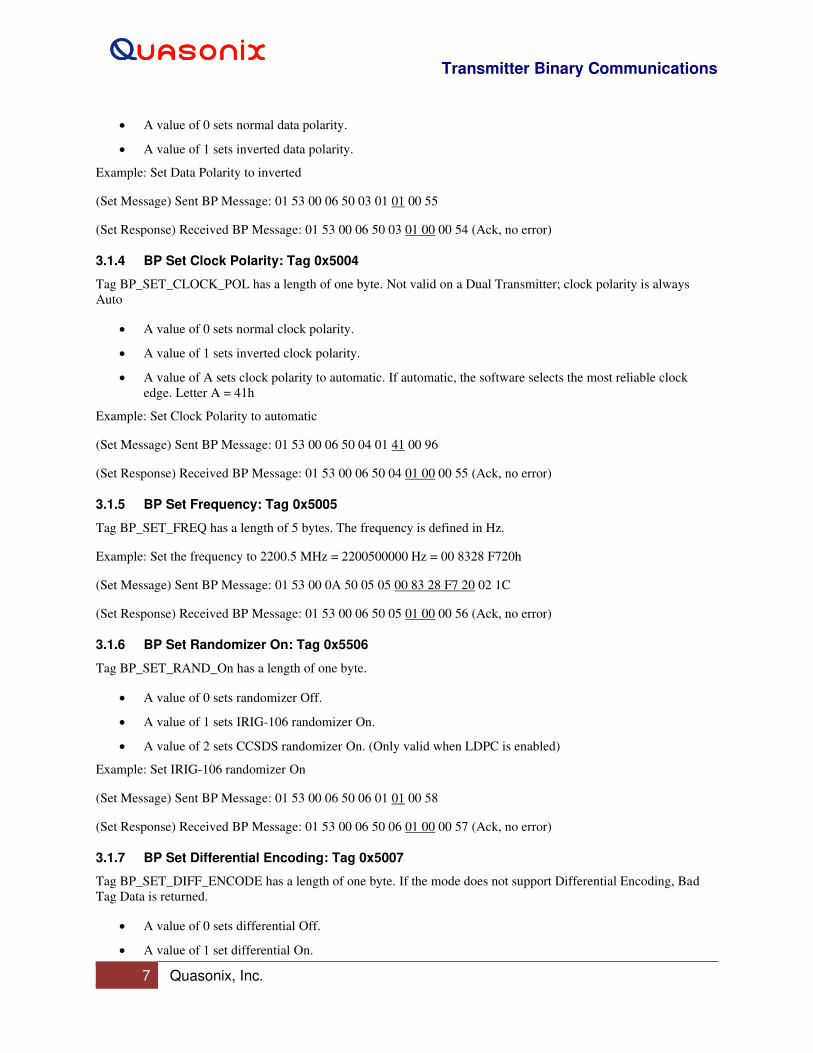
3.1.3 BP Set Data Polarity: Tag 0x5003
Tag BP_SET_DATA_POL has a length of one byte.
Transmitter Binary Communications
7 Quasonix, Inc.
• A value of 0 sets normal data polarity.
• A value of 1 sets inverted data polarity.
Example: Set Data Polarity to inverted
(Set Message) Sent BP Message: 01 53 00 06 50 03 01 01 00 55
(Set Response) Received BP Message: 01 53 00 06 50 03 01 00 00 54 (Ack, no error)
3.1.4 BP Set Clock Polarity: Tag 0x5004
Tag BP_SET_CLOCK_POL has a length of one byte. Not valid on a Dual Transmitter; clock polarity is always
Auto
• A value of 0 sets normal clock polarity.
• A value of 1 sets inverted clock polarity.
• A value of A sets clock polarity to automatic. If automatic, the software selects the most reliable clock
edge. Letter A = 41h
Example: Set Clock Polarity to automatic
(Set Message) Sent BP Message: 01 53 00 06 50 04 01 41 00 96
(Set Response) Received BP Message: 01 53 00 06 50 04 01 00 00 55 (Ack, no error)
3.1.5 BP Set Frequency: Tag 0x5005
Tag BP_SET_FREQ has a length of 5 bytes. The frequency is defined in Hz.
Example: Set the frequency to 2200.5 MHz = 2200500000 Hz = 00 8328 F720h
(Set Message) Sent BP Message: 01 53 00 0A 50 05 05 00 83 28 F7 20 02 1C
(Set Response) Received BP Message: 01 53 00 06 50 05 01 00 00 56 (Ack, no error)
3.1.6 BP Set Randomizer On: Tag 0x5506
Tag BP_SET_RAND_On has a length of one byte.
• A value of 0 sets randomizer Off.
• A value of 1 sets IRIG-106 randomizer On.
• A value of 2 sets CCSDS randomizer On. (Only valid when LDPC is enabled)
Example: Set IRIG-106 randomizer On
(Set Message) Sent BP Message: 01 53 00 06 50 06 01 01 00 58
(Set Response) Received BP Message: 01 53 00 06 50 06 01 00 00 57 (Ack, no error)
3.1.7 BP Set Differential Encoding: Tag 0x5007
Tag BP_SET_DIFF_ENCODE has a length of one byte. If the mode does not support Differential Encoding, Bad
Tag Data is returned.
• A value of 0 sets differential Off.
• A value of 1 set differential On.
Transmitter Binary Communications
8 Quasonix, Inc.
Example: Set Differential Encoding On
(Set Message) Sent BP Message: 01 53 00 06 50 07 01 01 00 59
(Set Response) Received BP Message: 01 53 00 06 50 07 01 00 00 58 (Ack, no error)
3.1.8 BP Set RF On: Tag 0x5008
Tag BP_SET_RF_ON has a length of one byte.
• A value of 0 sets RF output Off.
• A value of 1 sets RF output On.
Example: Set RF to Off
(Set Message) Sent BP Message: 01 53 00 06 50 08 01 00 00 59
(Set Response) Received BP Message: 01 53 00 06 50 08 01 00 00 59 (Ack, no error)
3.1.9 BP Set Clock Source: Tag 0x5009
Tag BP_SET_CLOCK_SOURCE has a length of one byte.
• A value of 0 sets clock source to external.
• A value of 1 sets clock source to internal.
Example: Set Clock Source to internal (1)
(Set Message) Sent BP Message: 01 53 00 06 50 09 01 01 00 5B
(Set Response) Received BP Message: 01 53 00 06 50 09 01 00 00 5A (Ack, no error)
3.1.10 BP Set Internal Clock: Tag 0x500A
Tag BP_SET_INT_CLOCK has a length of 4 bytes. The internal bit rate is defined in bits per second (bps).
Valid range is 0.002 MHz – 46.000 MHz
Example: Set Internal Clock to 8.13 MHz = 8130000 Hz = 007C 0DD0h
(Set Message) Sent BP Message: 01 53 00 09 50 0A 04 00 7C 0D D0 01 B7
(Set Response) Received BP Message: 01 53 00 06 50 0A 01 00 00 5B (Ack, no error)
3.1.11 BP Set Data Source: Tag 0x500B
Tag BP_SET_DATA_SOURCE has a length of one byte. This command is not supported by Dual Transmitters.
When Clock Source is set, Data Source is automatically set on a Dual Transmitter.
• A value of 0 indicates data source is external.
• A value of 1 indicates data source is internal.
Example: Set Data Source to internal (1)
(Set Message) Sent BP Message: 01 53 00 06 50 0B 01 01 00 5D
(Set Response) Received BP Message: 01 53 00 06 50 0B 01 00 00 5C (Ack, no error)
Transmitter Binary Communications
9 Quasonix, Inc.
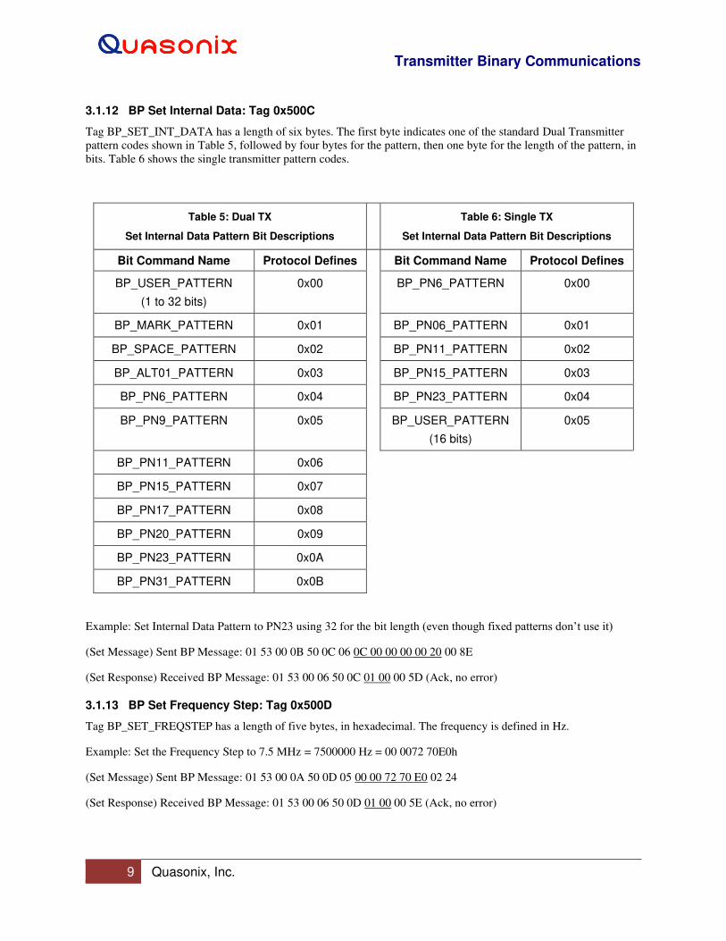
3.1.12 BP Set Internal Data: Tag 0x500C
Tag BP_SET_INT_DATA has a length of six bytes. The first byte indicates one of the standard Dual Transmitter
pattern codes shown in Table 5, followed by four bytes for the pattern, then one byte for the length of the pattern, in
bits. Table 6 shows the single transmitter pattern codes.
Table 5: Dual TX
Set Internal Data Pattern Bit Descriptions
Table 6: Single TX
Set Internal Data Pattern Bit Descriptions
Bit Command Name Protocol Defines Bit Command Name Protocol Defines
BP_USER_PATTERN
(1 to 32 bits)
0x00 BP_PN6_PATTERN 0x00
BP_MARK_PATTERN 0x01 BP_PN06_PATTERN 0x01
BP_SPACE_PATTERN 0x02 BP_PN11_PATTERN 0x02
BP_ALT01_PATTERN 0x03 BP_PN15_PATTERN 0x03
BP_PN6_PATTERN 0x04 BP_PN23_PATTERN 0x04
BP_PN9_PATTERN 0x05 BP_USER_PATTERN
(16 bits)
0x05
BP_PN11_PATTERN 0x06
BP_PN15_PATTERN 0x07
BP_PN17_PATTERN 0x08
BP_PN20_PATTERN 0x09
BP_PN23_PATTERN 0x0A
BP_PN31_PATTERN 0x0B
Example: Set Internal Data Pattern to PN23 using 32 for the bit length (even though fixed patterns don’t use it)
(Set Message) Sent BP Message: 01 53 00 0B 50 0C 06 0C 00 00 00 00 20 00 8E
(Set Response) Received BP Message: 01 53 00 06 50 0C 01 00 00 5D (Ack, no error)
3.1.13 BP Set Frequency Step: Tag 0x500D
Tag BP_SET_FREQSTEP has a length of five bytes, in hexadecimal. The frequency is defined in Hz.
Example: Set the Frequency Step to 7.5 MHz = 7500000 Hz = 00 0072 70E0h
(Set Message) Sent BP Message: 01 53 00 0A 50 0D 05 00 00 72 70 E0 02 24
(Set Response) Received BP Message: 01 53 00 06 50 0D 01 00 00 5E (Ack, no error)

Transmitter Binary Communications
10 Quasonix, Inc.
3.1.14 BP Set Variable Power New: Tag 0x500F
Tag BP_SET_VAR_POWER has a length of three bytes, in ASCII, with implied decimal, XX.X. Valid range is 0 to
31 in 1 dB steps, or 31.5 in 0.5 dB steps, depending on the transmitter.
Example: Set Variable Power New to 27.5 dB
(Set Message) Sent BP Message: 01 53 00 08 50 0F 03 32 37 35 01 00
(Set Response) Received BP Message: 01 53 00 06 50 0F 01 00 00 60 (Ack, no error)
3.1.15 BP Set High Power Level: Tag 0x5010
Tag BP_SET_HP_LEVEL has a length of three bytes, in ASCII, with implied decimal, XX.X. Valid range is 0 to 31
in 1 dB steps, or 31.5 in 0.5 dB steps, depending on the transmitter.
Example: Set High Power Level to 13 dB
(Set Message) Sent BP Message: 01 53 00 08 50 10 03 31 33 30 00 F7
(Set Response) Received BP Message: 01 53 00 06 50 10 01 00 00 61 (Ack, no error)
3.1.16 BP Set Low Power Level: Tag 0x5011
Tag BP_SET_LP_LEVEL has a length of three bytes, in ASCII, with implied decimal, XX.X. Valid range is 0 to 31
in 1 dB steps, or 31.5 in 0.5 dB steps, depending on the transmitter.
Example: Set Low Power Level to 4.5 dB
(Set Message) Sent BP Message: 01 53 00 08 50 11 03 30 34 35 00 FD
(Set Response) Received BP Message: 01 53 00 06 50 11 01 00 00 62 (Ack, no error)
3.1.17 BP Set Low Density Parity Check State: Tag 0x5012
Tag BP_SET_LDPC_STATE has a length of two bytes. The first byte indicates the enable (one) or disable (zero)
state. The second byte is the LDPC code. Valid code range is 0 through 5, as shown in Table 7.
Example: Set LDPC to On with LDPC code 4 (4096 4/5)
(Set Message) Sent BP Message: 01 53 00 07 50 12 02 01 04 00 69
(Set Response) Received BP Message: 01 53 00 06 50 12 01 00 00 63 (Ack, no error)
Table 7: LDPC Codes
LD6 Code Block Size and Code Rate
0 k=4096, r=1/2
1 k=1024, r=1/2
2 k=4096, r=2/3
3 k=1024, r=2/3
4 k=4096, r=4/5
Transmitter Binary Communications
11 Quasonix, Inc.
LD6 Code Block Size and Code Rate
5 k=1024, r=4/5
3.1.18 BP Set Convolutional Encoding State: Tag 0x5013
Tag BP_SET_CC_STATE has a length of one byte.
• A value of 0 disables convolutional encoding.
• A value of 1 enables convolutional encoding.
Example: Set Convolutional Encoding to enabled (1)
(Set Message) Sent BP Message: 01 53 00 06 50 13 01 01 00 65
(Set Response) Received BP Message: 01 53 00 06 50 13 01 00 00 64 (Ack, no error)
3.1.19 BP Set NRZ-M Encoding State: Tag 0x5014
Tag BP_SET_MC_STATE has a length of one byte.
• A value of 0 disables NRZ encoding.
• A value of 1 enables NRZ encoding.
Example: Set NRZ encoding to disabled (0)
(Set Message) Sent BP Message: 01 53 00 06 50 14 01 00 00 65
(Set Response) Received BP Message: 01 53 00 06 50 14 01 00 00 65 (Ack, no error)
3.1.20 BP Set Channel Delay Enable State: Tag 0x5015
Tag BP_SET_CDE_STATE has a length of one byte. This command is valid on Dual Transmitters only.
• A value of 0 indicates channel delay is disabled.
• A value of 1 indicates channel delay is enabled.
Example: Set Channel Delay to enabled (1)
(Set Message) Sent BP Message: 01 53 00 06 50 15 01 01 00 67
(Set Response) Received BP Message: 01 53 00 06 50 15 01 00 00 66 (Ack, no error)
3.1.21 BP Set Channel Delay Value: Tag 0x5016
Tag BP_SET_CD_VALUE has a length of three bytes in 0.01 nanosecond or hundredths of nanoseconds. This
command is valid on Dual Transmitters only.
Valid range is 0 to 5000.00 ns.
Example: Set Channel Delay Value to 42.00 ns = 4200 hundredths of nanoseconds = 00 1068h
(Set Message) Sent BP Message: 01 53 00 08 50 16 03 00 10 68 00 E1
(Set Response) Received BP Message: 01 53 00 06 50 16 01 00 00 67 (Ack, no error)
Transmitter Binary Communications
12 Quasonix, Inc.
3.1.22 BP Set Modulation Scaling Value: Tag 0x5017
Tag BP_SET_MS_VALUE has a length of five bytes, in ASCII, with implied decimal, XXX.XX. Valid range is
0.09 to 128.01.
Example: Set Modulation Scaling to 21 = 021.00 (implied decimal) = 30 32 31 30 30
(Set Message) Sent BP Message: 01 53 00 0A 50 17 05 30 32 31 30 30 01 5F
(Set Response) Received BP Message: 01 53 00 06 50 17 01 00 00 68 (Ack
3.1.23 BP Set Automatic Carrier Output Enable: Tag 0x5250
Tag BP_SET_AC_ENABLE has a length of one byte.
• A value of 0 indicates automatic carrier output is Off/disabled.
• A value of 1 indicates automatic carrier output is On/enabled.
Example: Set Automatic Carrier Output to On/enabled (1)
(Set Message) Sent BP Message: 01 53 00 06 52 50 01 01 00 A4
(Set Response) Received BP Message: 01 53 00 06 52 50 01 00 00 A3 (Ack, no error)
3.1.24 BP Set Clock Free Disable: Tag 0x5251
Tag BP_SET_CF_DISABLE has a length of one byte.
• A value of 0 indicates clock free operation is enabled (uses the internal bit sync)
• A value of 1 indicates clock free operation is disabled; normal operation with an external clock
Example: Set Clock Free operation to disabled (1)
(Set Message) Sent BP Message: 01 53 00 06 52 51 01 01 00 A5
(Set Response) Received BP Message: 01 53 00 06 52 51 01 00 00 A4 (Ack, no error)
3.1.25 BP Set RF On/Off Pin Polarity State: Tag 0x5252
Tag BP_SET_RZ_STATE has a length of one byte.
• A value of 0 indicates RF On when pin is low.
• A value of 1 indicates RF On when pin is high or left unconnected.
Example: Set RF On/Off Pin value to 1 (high)
(Set Message) Sent BP Message: 01 53 00 06 52 52 01 01 00 A6
(Set Response) Received BP Message: 01 53 00 06 52 52 01 00 00 A5 (Ack, no error)
3.1.26 BP Set Overtemperature Control State: Tag 0x5253
Tag BP_SET_OC_STATE has a length of one byte.
• A value of 0 indicates overtemperature control is Off/disabled.
• A value of 1 indicates overtemperature control is On/enabled.
Example: Set the Overtemperature Control to On/enabled (1)
Transmitter Binary Communications
13 Quasonix, Inc.
(Set Message) Sent BP Message: 01 53 00 06 52 53 01 01 00 A7
(Set Response) Received BP Message: 01 53 00 06 52 53 01 00 00 A6 (Ack, no error)
3.1.27 BP Set ASCII Passthrough Enable: Tag 0x5254
Tag BP_SET_BP_PASSTHRU_ENABLE has a length of one byte. All subsequent terminal output messages are
encapsulated in binary protocol packets and sent to the “master,” until an Escape is entered at the terminal, or Asc
Passthru is set to (0) Off/disabled.
• A value of 0 indicates binary protocol passthrough is Off/disabled.
• A value of 1 indicates binary protocol passthrough is On/enabled.
Example: Set the binary protocol passthrough to enabled (1)
(Set Message) Sent BP Message: 01 53 00 06 52 54 01 01 00 A8
(Set Response) Received BP Message: 01 53 00 06 52 54 01 00 00 A7 (Ack, no error)
3.1.28 BP Set Dual Transmitter Channel: Tag 0x5400
Tag BP_DTX_SET_CHANNEL has a length of one byte. This command is valid on Dual Transmitters only.
• A value of 1 indicates channel 1.
• A value of 2 indicates channel 2.
• A value of 3 indicates channel 1 and channel 2.
Example: Set dual transmitter channel to 2
(Set Message) Sent BP Message: 01 53 00 06 54 00 01 02 00 57
(Set Response) Received BP Message: 01 53 00 06 54 00 01 00 00 55 (Ack, no error)
3.1.29 BP Send ASCII Passthrough Message: Tag 0x5401
Tag BP_SEND_ASCII_PASSTHRU_MSG has a length dependent on the ASCII command being sent. Requires
ASCII Passthru set to enabled (1) or the command is ignored.
Example: Send FR command (not case sensitive) = Length 4, Data = f r CR LF
(Set Message) Sent BP Message: 01 53 00 09 54 01 04 66 72 0D 0A 01 48
(Set Response) Received BP Message: 01 53 00 05 54 01 00 00 55 (Ack, no error)
3.1.30 BP ASCII Passthrough Message: Tag 0x5402
The BP_ASCII_PASSTHRU_MSG tag is sent by the transmitter for any message that would normally display in a
Transmitter Terminal screen. Since ASCII Passthrough is enabled, it is a binary protocol encapsulated response.
This is an ASCII passthrough message.
Example: Response to ASCII Send in section 3.1.29 of FR <CR>
(Set Response) Received BP Message (for the first line displayed): 01 53 00 27 54 02 22 43 68 61 6E 20 32 20 46
72 65 71 20 63 75 72 72 65 6E 74 6C 79 20 34 34 34 33 2E 30 20 4D 48 7A 0A 0D 0A 8D
Chan 2 Freq currently 4443.0 MHz <LF><CR>

Transmitter Binary Communications
14 Quasonix, Inc.
(Set Response) Received BP Message (for the second line displayed): 01 53 00 0E 54 02 09 32 5F 53 4F 51 50 53
4B 3E 03 0F
2_SOQPSK>
Transmitter Binary Communications
15 Quasonix, Inc.
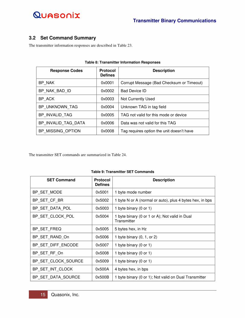
3.2 Set Command Summary
The transmitter information responses are described in Table 23.
Table 8: Transmitter Information Responses
Response Codes Protocol Defines
Description
BP_NAK 0x0001 Corrupt Message (Bad Checksum or Timeout)
BP_NAK_BAD_ID 0x0002 Bad Device ID
BP_ACK 0x0003 Not Currently Used
BP_UNKNOWN_TAG 0x0004 Unknown TAG in tag field
BP_INVALID_TAG 0x0005 TAG not valid for this mode or device
BP_INVALID_TAG_DATA 0x0006 Data was not valid for this TAG
BP_MISSING_OPTION 0x0008 Tag requires option the unit doesn’t have
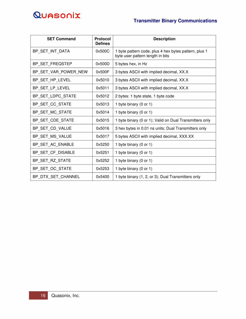
The transmitter SET commands are summarized in Table 24.
Table 9: Transmitter SET Commands
SET Command Protocol Defines
Description
BP_SET_MODE 0x5001 1 byte mode number
BP_SET_CF_BR 0x5002 1 byte N or A (normal or auto), plus 4 bytes hex, in bps
BP_SET_DATA_POL 0x5003 1 byte binary (0 or 1)
BP_SET_CLOCK_POL 0x5004 1 byte binary (0 or 1 or A); Not valid in Dual Transmitter
BP_SET_FREQ 0x5005 5 bytes hex, in Hz
BP_SET_RAND_On 0x5006 1 byte binary (0, 1, or 2)
BP_SET_DIFF_ENCODE 0x5007 1 byte binary (0 or 1)
BP_SET_RF_On 0x5008 1 byte binary (0 or 1)
BP_SET_CLOCK_SOURCE 0x5009 1 byte binary (0 or 1)
BP_SET_INT_CLOCK 0x500A 4 bytes hex, in bps
BP_SET_DATA_SOURCE 0x500B 1 byte binary (0 or 1); Not valid on Dual Transmitter
Transmitter Binary Communications
16 Quasonix, Inc.
SET Command Protocol Defines
Description
BP_SET_INT_DATA 0x500C 1 byte pattern code, plus 4 hex bytes pattern, plus 1 byte user pattern length in bits
BP_SET_FREQSTEP 0x500D 5 bytes hex, in Hz
BP_SET_VAR_POWER_NEW 0x500F 3 bytes ASCII with implied decimal, XX.X
BP_SET_HP_LEVEL 0x5010 3 bytes ASCII with implied decimal, XX.X
BP_SET_LP_LEVEL 0x5011 3 bytes ASCII with implied decimal, XX.X
BP_SET_LDPC_STATE 0x5012 2 bytes: 1 byte state, 1 byte code
BP_SET_CC_STATE 0x5013 1 byte binary (0 or 1)
BP_SET_MC_STATE 0x5014 1 byte binary (0 or 1)
BP_SET_CDE_STATE 0x5015 1 byte binary (0 or 1); Valid on Dual Transmitters only
BP_SET_CD_VALUE 0x5016 3 hex bytes in 0.01 ns units; Dual Transmitters only
BP_SET_MS_VALUE 0x5017 5 bytes ASCII with implied decimal, XXX.XX
BP_SET_AC_ENABLE 0x5250 1 byte binary (0 or 1)
BP_SET_CF_DISABLE 0x5251 1 byte binary (0 or 1)
BP_SET_RZ_STATE 0x5252 1 byte binary (0 or 1)
BP_SET_OC_STATE 0x5253 1 byte binary (0 or 1)
BP_DTX_SET_CHANNEL 0x5400 1 byte binary (1, 2, or 3); Dual Transmitters only

Transmitter Binary Communications
17 Quasonix, Inc.
4 Transmitter Get Command Tag Definitions
4.1 Get Commands
This section provides all of the tag definitions for the transmitter Get commands.
Get Tag messages sent to the transmitter ALL have a length of zero (0). The following sections describe the
Get Responses, which are NOT zero.
4.1.1 BP Get Binary Protocol Version: Tag 0x4000
Tag BP_GET_BP_VERSION response has a length of four bytes, in ASCII, with an implied decimal, X.XXXX.
Example:
(Get Message) Sent Message: 01 53 00 05 40 00 00 00 40
(Get Response) Received Message: 01 53 00 09 40 00 04 31 30 30 36 01 0B
Binary Protocol Version = 1.006
4.1.2 BP Get Device Model Number: Tag 0x4001
Tag BP_GET_DEVICE_MODELNUM response returns the model number as it is stored on the transmitter. The
length may vary, but is always in the Tag length byte (as shown underlined in the response below). This is the
Quasonix internal model number, not the customer part number. Use ASCII Passthru to display the customer part
number.
Example:
(Get Message) Sent Message: 01 53 00 05 40 01 00 00 41
(Get Response) Received Message: 01 53 00 2A 40 01 25 51 53 58 2D 56 45 52 2D 31 31 31 2D 31 30 53 2D 32 30
2D 50 4B 47 2D 56 50 2D 53 54 43 2D 53 42 53 2D 4C 44 36 09 AD
Model Number = QSX-VER-111-10S-20-PKG-VP-STC-SBS-LD6
4.1.3 BP Get Device Serial Number: Tag 0x4002
Tag BP_GET_DEVICE_SERNUM response returns the serial number as it is stored on the transmitter. The length
may vary, but is always in the Tag length byte (as shown underlined in the response below).
Example:
(Get Message) Sent Message: 01 53 00 05 40 02 00 00 42
(Get Response) Received Message: 01 53 00 0B 40 02 06 31 30 30 31 0A 0D 01 21
Serial Number = 1001 <LF> <CR>
4.1.4 BP Get Software Version: Tag 0x4003
Tag BP_GET_SOFTWARE_VER response has a variable length of ASCII bytes based on the length of the software
version.
Transmitter Binary Communications
18 Quasonix, Inc.
Example:
(Get Message) Sent Message: 01 53 00 05 40 03 00 00 43
(Get Response) Received Message: 01 53 00 30 40 03 2B 44 75 61 6C 20 54 58 20 46 69 72 6D 77 61 72 65 20 52
65 76 3A 20 44 54 58 20 56 31 2E 32 30 34 20 20 31 2F 31 30 2F 32 30 31 39 0C 1B
Software Version = Dual TX Firmware Rev: DTX V1.204 1/10/2019
4.1.5 BP Get FPGA Version: Tag 0x4004
Tag BP_GET_FPGA_VER response returns the FPGA version as it is stored on the transmitter. The length may
vary, but is always in the Tag length byte (as shown underlined in the response below).
Example:
(Get Message) Sent Message: 01 53 00 05 40 04 00 00 44
(Get Response) Received Message: 01 53 00 1C 40 04 17 44 54 58 20 46 50 47 41 20 52 65 76 3A 20 30 30 30 68
20 30 31 31 68 06 42
FPGA Version = DTX FPGA Rev: 000h 011h
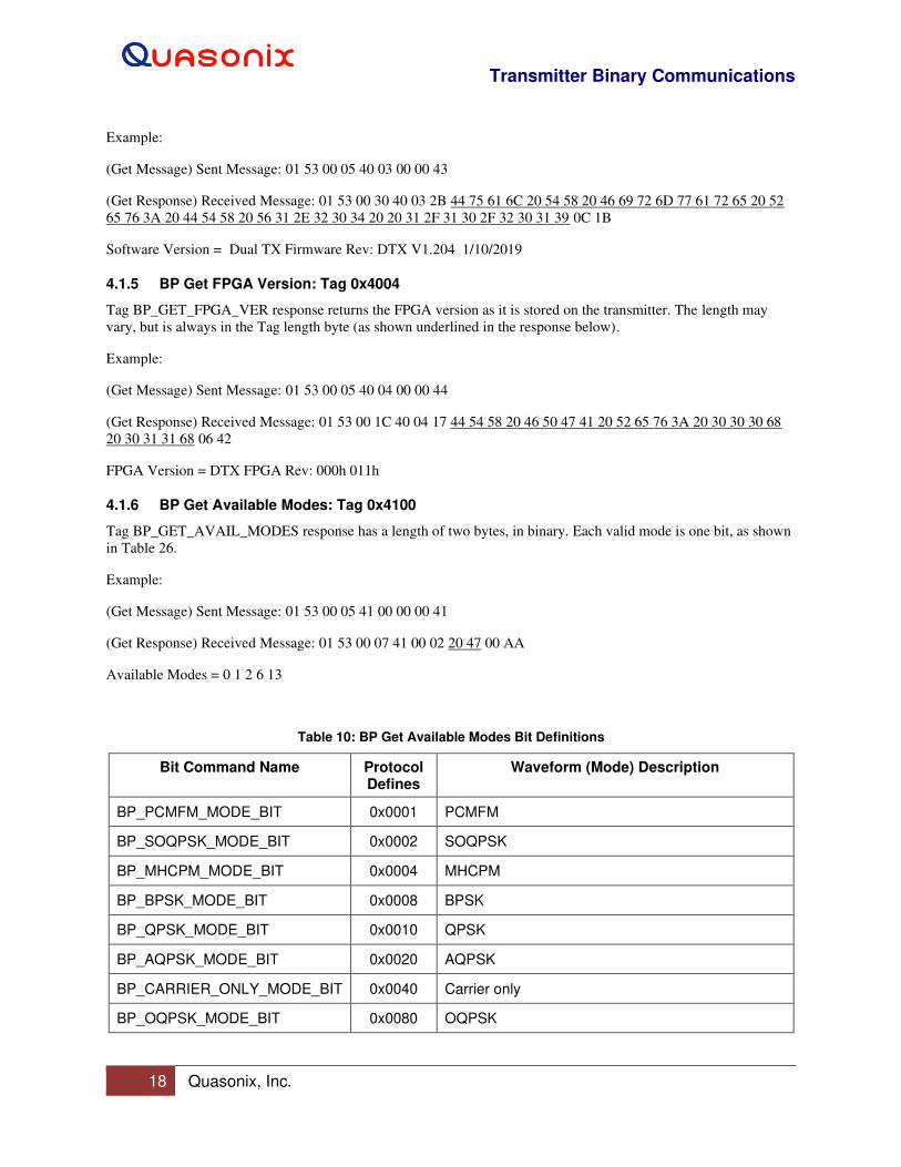
4.1.6 BP Get Available Modes: Tag 0x4100
Tag BP_GET_AVAIL_MODES response has a length of two bytes, in binary. Each valid mode is one bit, as shown
in Table 26.
Example:
(Get Message) Sent Message: 01 53 00 05 41 00 00 00 41
(Get Response) Received Message: 01 53 00 07 41 00 02 20 47 00 AA
Available Modes = 0 1 2 6 13
Table 10: BP Get Available Modes Bit Definitions
Bit Command Name Protocol Defines
Waveform (Mode) Description
BP_PCMFM_MODE_BIT 0x0001 PCMFM
BP_SOQPSK_MODE_BIT 0x0002 SOQPSK
BP_MHCPM_MODE_BIT 0x0004 MHCPM
BP_BPSK_MODE_BIT 0x0008 BPSK
BP_QPSK_MODE_BIT 0x0010 QPSK
BP_AQPSK_MODE_BIT 0x0020 AQPSK
BP_CARRIER_ONLY_MODE_BIT 0x0040 Carrier only
BP_OQPSK_MODE_BIT 0x0080 OQPSK
Transmitter Binary Communications
19 Quasonix, Inc.
Bit Command Name Protocol Defines
Waveform (Mode) Description
BP_UQPSK_MODE_BIT 0x0100 UQPSK
BP_AUQPSK_MODE_BIT 0x0200 AUQPSK
BP_STDN_MODE_BIT 0x0400 Spacecraft Tracking and Data Network or PM/BPSK
BP_SQPN_MODE_BIT 0x0800 Staggered Quadrature Pseudo-random Noise
BP_AFM_MODE_BIT 0x1000 Analog FM
BP_STC_MODE_BIT 0x2000 Space Time Coding (STC) (Dual Transmitter Only)
BP_DPM_MODE_BIT 0x4000 Digital Phase Modulation (DPM)
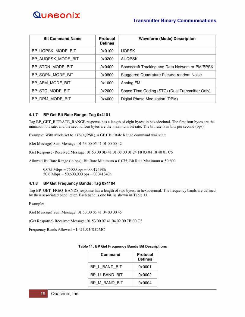
4.1.7 BP Get Bit Rate Range: Tag 0x4101
Tag BP_GET_BITRATE_RANGE response has a length of eight bytes, in hexadecimal. The first four bytes are the
minimum bit rate, and the second four bytes are the maximum bit rate. The bit rate is in bits per second (bps).
Example: With Mode set to 1 (SOQPSK), a GET Bit Rate Range command was sent:
(Get Message) Sent Message: 01 53 00 05 41 01 00 00 42
(Get Response) Received Message: 01 53 00 0D 41 01 08 00 01 24 F8 03 04 18 40 01 C6
Allowed Bit Rate Range (in bps): Bit Rate Minimum = 0.075, Bit Rate Maximum = 50.600
0.075 Mbps = 75000 bps = 000124F8h
50.6 Mbps = 50,600,000 bps = 03041840h
4.1.8 BP Get Frequency Bands: Tag 0x4104
Tag BP_GET_FREQ_BANDS response has a length of two bytes, in hexadecimal. The frequency bands are defined
by their associated band letter. Each band is one bit, as shown in Table 11.
Example:
(Get Message) Sent Message: 01 53 00 05 41 04 00 00 45
(Get Response) Received Message: 01 53 00 07 41 04 02 00 7B 00 C2
Frequency Bands Allowed = L U LS US C MC
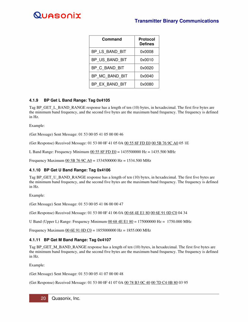
Table 11: BP Get Frequency Bands Bit Descriptions
Command Protocol Defines
BP_L_BAND_BIT 0x0001
BP_U_BAND_BIT 0x0002
BP_M_BAND_BIT 0x0004
Transmitter Binary Communications
20 Quasonix, Inc.
Command Protocol Defines
BP_LS_BAND_BIT 0x0008
BP_US_BAND_BIT 0x0010
BP_C_BAND_BIT 0x0020
BP_MC_BAND_BIT 0x0040
BP_EX_BAND_BIT 0x0080
4.1.9 BP Get L Band Range: Tag 0x4105
Tag BP_GET_L_BAND_RANGE response has a length of ten (10) bytes, in hexadecimal. The first five bytes are
the minimum band frequency, and the second five bytes are the maximum band frequency. The frequency is defined
in Hz.
Example:
(Get Message) Sent Message: 01 53 00 05 41 05 00 00 46
(Get Response) Received Message: 01 53 00 0F 41 05 0A 00 55 8F FD E0 00 5B 76 9C A0 05 1E
L Band Range: Frequency Minimum 00 55 8F FD E0 = 1435500000 Hz = 1435.500 MHz
Frequency Maximum 00 5B 76 9C A0 = 1534500000 Hz = 1534.500 MHz
4.1.10 BP Get U Band Range: Tag 0x4106
Tag BP_GET_U_BAND_RANGE response has a length of ten (10) bytes, in hexadecimal. The first five bytes are
the minimum band frequency, and the second five bytes are the maximum band frequency. The frequency is defined
in Hz.
Example:
(Get Message) Sent Message: 01 53 00 05 41 06 00 00 47
(Get Response) Received Message: 01 53 00 0F 41 06 0A 00 68 4E E1 80 00 6E 91 0D C0 04 34
U Band (Upper L) Range: Frequency Minimum 00 68 4E E1 80 = 175000000 Hz = 1750.000 MHz
Frequency Maximum 00 6E 91 0D C0 = 1855000000 Hz = 1855.000 MHz
4.1.11 BP Get M Band Range: Tag 0x4107
Tag BP_GET_M_BAND_RANGE response has a length of ten (10) bytes, in hexadecimal. The first five bytes are
the minimum band frequency, and the second five bytes are the maximum band frequency. The frequency is defined
in Hz.
Example:
(Get Message) Sent Message: 01 53 00 05 41 07 00 00 48
(Get Response) Received Message: 01 53 00 0F 41 07 0A 00 78 B3 0C 40 00 7D C4 0B 80 03 95

Transmitter Binary Communications
21 Quasonix, Inc.
M Band Range: Frequency Minimum 00 78 B3 0C 40 = 2025000000 Hz = 2025.000 MHz
Frequency Maximum 00 7D C4 0B 80 = 2100000000 Hz = 2110.000 MHz
4.1.12 BP Get LS Band Range: Tag 0x4108
Tag BP_GET_LS_BAND_RANGE response has a length of ten (10) bytes, in hexadecimal. The first five bytes are
the minimum band frequency, and the second five bytes are the maximum band frequency. The frequency is defined
in Hz.
Example:
(Get Message) Sent Message: 01 53 00 05 41 08 00 00 49
(Get Response) Received Message: 01 53 00 0F 41 08 0A 00 83 28 F7 20 00 89 1E D8 20 03 B4
LS Band (Lower S) Range: Frequency Minimum 00 83 28 F7 20 = 2200500000 Hz = 2200.500 MHz
Frequency Maximum 00 89 1E D8 20 = 2300500000 Hz = 2300.500 MHz
4.1.13 BP Get US Band Range: Tag 0x4109
Tag BP_GET_US_BAND_RANGE response has a length of ten (10) bytes, in hexadecimal. The first five bytes are
the minimum band frequency, and the second five bytes are the maximum band frequency. The frequency is defined
in Hz.
Example:
(Get Message) Sent Message: 01 53 00 05 41 09 00 00 4A
(Get Response) Received Message: 01 53 00 0F 41 09 0A 00 89 1E D8 20 00 8E B9 2B A0 04 05
US Band (Upper S) Range: Frequency Minimum 00 89 1E D8 20 = 2300500000 Hz = 2300.500 MHz
Frequency Maximum 00 8E B9 2B A0 = 2394500000 Hz = 2394.500 MHz
4.1.14 BP Get C Band Range: Tag 0x410A
Tag BP_GET_C_BAND_RANGE response has a length of ten (10) bytes, in hexadecimal. The first five bytes are
the minimum band frequency, and the second five bytes are the maximum band frequency. The frequency is defined
in Hz.
Example:
(Get Message) Sent Message: 01 53 00 05 41 0A 00 00 4B
(Get Response) Received Message: 01 53 00 0F 41 0A 01 06 42 AC 00 01 27 0B 01 80 01 FE
C Band Range: Frequency Minimum = 4400000000 Hz = 4400.000 MHz
Frequency Maximum = 4950000000 Hz = 4950.000 MHz
4.1.15 BP Get MC Band Range: Tag 0x410B
Tag BP_GET_MC_BAND_RANGE response has a length of ten (10) bytes, in hexadecimal. The first five bytes are
the minimum band frequency, and the second five bytes are the maximum band frequency. The frequency is defined
in Hz.
Transmitter Binary Communications
22 Quasonix, Inc.
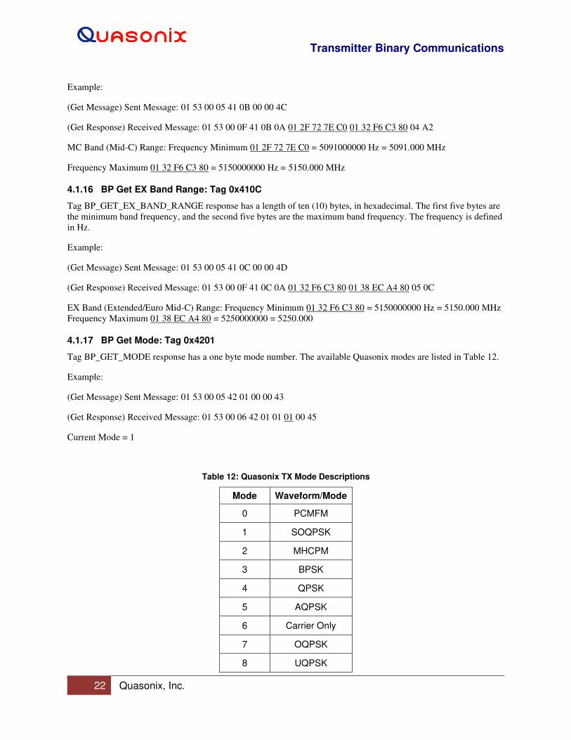
Example:
(Get Message) Sent Message: 01 53 00 05 41 0B 00 00 4C
(Get Response) Received Message: 01 53 00 0F 41 0B 0A 01 2F 72 7E C0 01 32 F6 C3 80 04 A2
MC Band (Mid-C) Range: Frequency Minimum 01 2F 72 7E C0 = 5091000000 Hz = 5091.000 MHz
Frequency Maximum 01 32 F6 C3 80 = 5150000000 Hz = 5150.000 MHz
4.1.16 BP Get EX Band Range: Tag 0x410C
Tag BP_GET_EX_BAND_RANGE response has a length of ten (10) bytes, in hexadecimal. The first five bytes are
the minimum band frequency, and the second five bytes are the maximum band frequency. The frequency is defined
in Hz.
Example:
(Get Message) Sent Message: 01 53 00 05 41 0C 00 00 4D
(Get Response) Received Message: 01 53 00 0F 41 0C 0A 01 32 F6 C3 80 01 38 EC A4 80 05 0C
EX Band (Extended/Euro Mid-C) Range: Frequency Minimum 01 32 F6 C3 80 = 5150000000 Hz = 5150.000 MHz
Frequency Maximum 01 38 EC A4 80 = 5250000000 = 5250.000
4.1.17 BP Get Mode: Tag 0x4201
Tag BP_GET_MODE response has a one byte mode number. The available Quasonix modes are listed in Table 12.
Example:
(Get Message) Sent Message: 01 53 00 05 42 01 00 00 43
(Get Response) Received Message: 01 53 00 06 42 01 01 01 00 45
Current Mode = 1
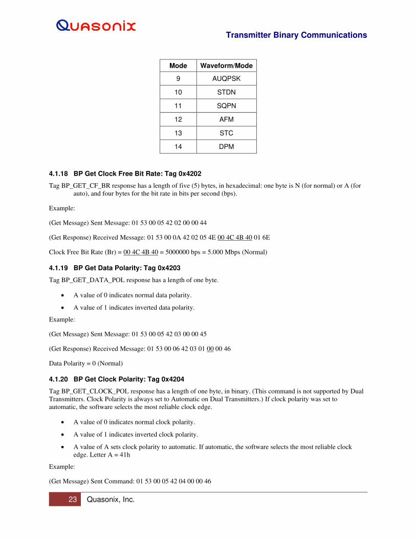
Table 12: Quasonix TX Mode Descriptions
Mode Waveform/Mode
0 PCMFM
1 SOQPSK
2 MHCPM
3 BPSK
4 QPSK
5 AQPSK
6 Carrier Only
7 OQPSK
8 UQPSK
Transmitter Binary Communications
23 Quasonix, Inc.
Mode Waveform/Mode
9 AUQPSK
10 STDN
11 SQPN
12 AFM
13 STC
14 DPM
4.1.18 BP Get Clock Free Bit Rate: Tag 0x4202
Tag BP_GET_CF_BR response has a length of five (5) bytes, in hexadecimal: one byte is N (for normal) or A (for
auto), and four bytes for the bit rate in bits per second (bps).
Example:
(Get Message) Sent Message: 01 53 00 05 42 02 00 00 44
(Get Response) Received Message: 01 53 00 0A 42 02 05 4E 00 4C 4B 40 01 6E
Clock Free Bit Rate (Br) = 00 4C 4B 40 = 5000000 bps = 5.000 Mbps (Normal)
4.1.19 BP Get Data Polarity: Tag 0x4203
Tag BP_GET_DATA_POL response has a length of one byte.
• A value of 0 indicates normal data polarity.
• A value of 1 indicates inverted data polarity.
Example:
(Get Message) Sent Message: 01 53 00 05 42 03 00 00 45
(Get Response) Received Message: 01 53 00 06 42 03 01 00 00 46
Data Polarity = 0 (Normal)
4.1.20 BP Get Clock Polarity: Tag 0x4204
Tag BP_GET_CLOCK_POL response has a length of one byte, in binary. (This command is not supported by Dual
Transmitters. Clock Polarity is always set to Automatic on Dual Transmitters.) If clock polarity was set to
automatic, the software selects the most reliable clock edge.
• A value of 0 indicates normal clock polarity.
• A value of 1 indicates inverted clock polarity.
• A value of A sets clock polarity to automatic. If automatic, the software selects the most reliable clock
edge. Letter A = 41h
Example:
(Get Message) Sent Command: 01 53 00 05 42 04 00 00 46
Transmitter Binary Communications
24 Quasonix, Inc.
(Get Response) Received Command: 01 53 00 06 42 04 01 00 00 47
Clock Polarity = 0 (Normal)
4.1.21 BP Get Frequency: Tag 0x4205
Tag BP_GET_FREQ response has a length of five (5) bytes, in hexadecimal. The frequency is defined in Hz.
Example:
(Get Message) Sent Command: 01 53 00 05 42 05 00 00 47
(Get Response) Received Command: 01 53 00 0A 42 05 05 00 87 A1 5F E0 02 B3
Frequency 00 87 A1 5F E0 = 2275500000 Hz = 2275.500 MHz
4.1.22 BP Get Randomizer On: Tag 0x4206
Tag BP_GET_RAND_On response has a length of one byte, in binary.
• A value of 0 indicates randomizer Off.
• A value of 1 indicates IRIG-106 randomizer On.
• A value of 2 indicates CCSDS randomizer On.
Example:
(Get Message) Sent Command: 01 53 00 05 42 06 00 00 48
(Get Response) Received Command: 01 53 00 06 42 06 01 00 00 49
Randomizer = 0 (Off)
4.1.23 BP Get Differential Encoding: Tag 0x4207
Tag BP_GET_DIFF_ENCODE response has a length of one byte, in binary.
• A value of 0 indicates differential Off.
• A value of 1 indicates differential On.
Example:
(Get Message) Sent Command: 01 53 00 05 42 07 00 00 49
(Get Response) Received Command: 01 53 00 06 42 07 01 01 00 4B
Differential Encoding = 1 (On)
4.1.24 BP Get RF State: Tag 0x4208
Tag BP_GET_RF_STATE response has a length of two bytes. One byte is for the RF setting, and the other byte is
the actual RF state.
• A value of 0 indicates RF output Off/disabled.
• A value of 1 indicates RF output On/enabled.
Transmitter Binary Communications
25 Quasonix, Inc.
Example:
(Get Message) Sent Message: 01 53 00 05 42 08 00 00 4A
(Get Response) Received Message: 01 53 00 07 42 08 02 00 00 00 4C
RF On State = 0 (Off), Actual RF = Off
4.1.25 BP Get Clock Source: Tag 0x4209
Tag BP_GET_CLOCK_SOURCE response has a length of one byte, in binary.
• A value of 0 indicates clock source is external.
• A value of 1 indicates clock source is internal.
Example:
(Get Message) Sent Message: 01 53 00 05 42 09 00 00 4B
(Get Response) Received Message: 01 53 00 06 42 09 01 00 00 4C
Clock Source = 0 (External)
4.1.26 BP Get Internal Clock: Tag 0x420A
Tag BP_GET_INT_CLOCK response has a length of four bytes, in hexadecimal. The returned internal bit rate is in
bits per second.
Example:
(Get Message) Sent Message: 01 53 00 05 42 0A 00 00 4C
(Get Response) Received Message: 01 53 00 09 42 0A 04 00 4C 4B 40 01 27
Internal Clock = 00 4C 4B 40 = 5000000 bps = 5.000 MHz
4.1.27 BP Get Data Source: Tag 0x420B
Tag BP_GET_DATA_SOURCE response has a length of one byte, in binary. This command is not supported by
Dual Transmitters.
• A value of 0 indicates data source is external.
• A value of 1 indicates data source is internal.
Example:
(Get Message) Sent Message: 01 53 00 05 42 0B 00 00 4D
(Get Response) Received Message: 01 53 00 06 42 0B 01 00 00 4E
Data Source = 0 (External)
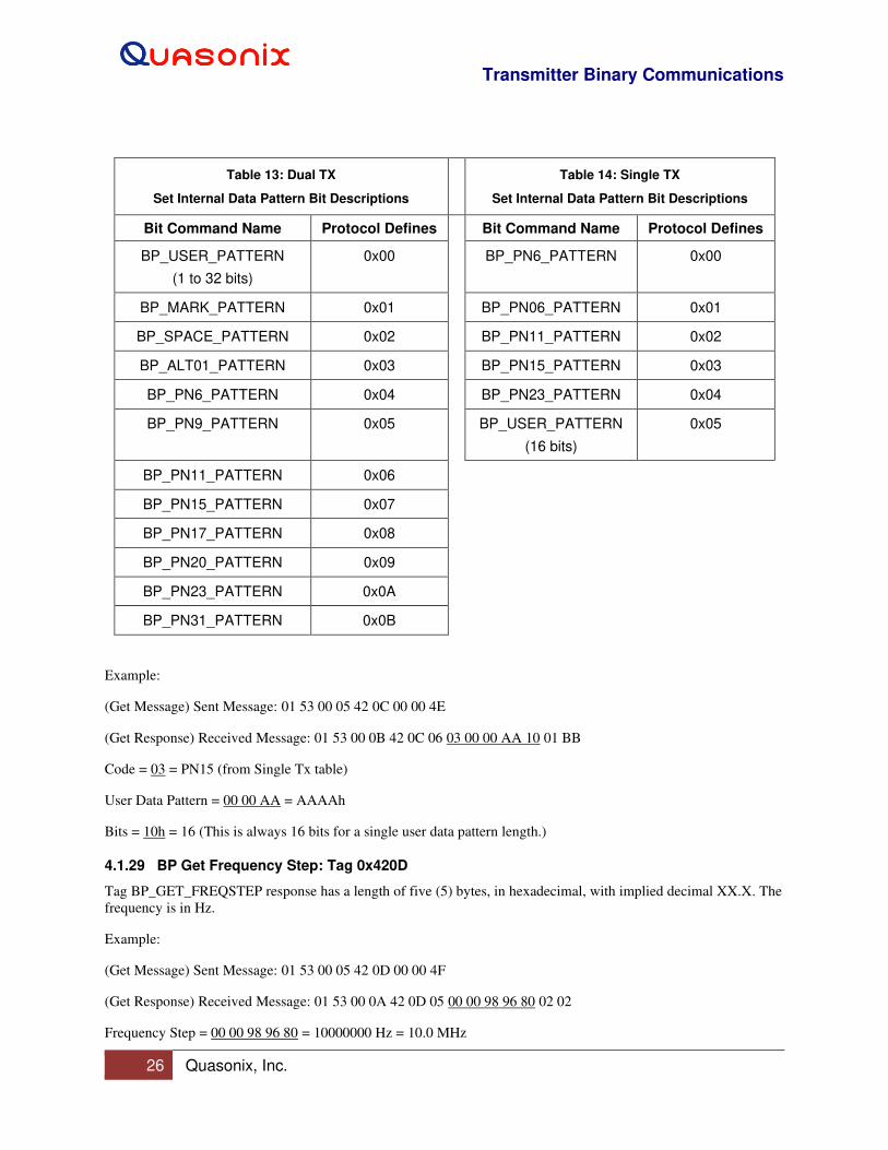
4.1.28 BP Get Internal Data: Tag 0x420C
Tag BP_GET_INT_DATA response has a length of six bytes, in hexadecimal. The first byte indicates one of the
standard Dual Transmitter pattern codes shown in Table 13, followed by four bytes for the pattern, then one byte for
the length of the user pattern, in bits. Table 14 shows the single transmitter pattern codes.
Transmitter Binary Communications
26 Quasonix, Inc.
Table 13: Dual TX
Set Internal Data Pattern Bit Descriptions
Table 14: Single TX
Set Internal Data Pattern Bit Descriptions
Bit Command Name Protocol Defines Bit Command Name Protocol Defines
BP_USER_PATTERN
(1 to 32 bits)
0x00 BP_PN6_PATTERN 0x00
BP_MARK_PATTERN 0x01 BP_PN06_PATTERN 0x01
BP_SPACE_PATTERN 0x02 BP_PN11_PATTERN 0x02
BP_ALT01_PATTERN 0x03 BP_PN15_PATTERN 0x03
BP_PN6_PATTERN 0x04 BP_PN23_PATTERN 0x04
BP_PN9_PATTERN 0x05 BP_USER_PATTERN
(16 bits)
0x05
BP_PN11_PATTERN 0x06
BP_PN15_PATTERN 0x07
BP_PN17_PATTERN 0x08
BP_PN20_PATTERN 0x09
BP_PN23_PATTERN 0x0A
BP_PN31_PATTERN 0x0B
Example:
(Get Message) Sent Message: 01 53 00 05 42 0C 00 00 4E
(Get Response) Received Message: 01 53 00 0B 42 0C 06 03 00 00 AA 10 01 BB
Code = 03 = PN15 (from Single Tx table)
User Data Pattern = 00 00 AA = AAAAh
Bits = 10h = 16 (This is always 16 bits for a single user data pattern length.)
4.1.29 BP Get Frequency Step: Tag 0x420D
Tag BP_GET_FREQSTEP response has a length of five (5) bytes, in hexadecimal, with implied decimal XX.X. The
frequency is in Hz.
Example:
(Get Message) Sent Message: 01 53 00 05 42 0D 00 00 4F
(Get Response) Received Message: 01 53 00 0A 42 0D 05 00 00 98 96 80 02 02
Frequency Step = 00 00 98 96 80 = 10000000 Hz = 10.0 MHz
Transmitter Binary Communications
27 Quasonix, Inc.
4.1.30 BP Get Variable Power New: Tag 0x420F
Tag BP_GET_VAR_POWER_NEW response has a length of three (3) bytes, in ASCII, with implied decimal,
XX.X. Valid range is 0 to 31 in 1.0 dB steps, or 31.5 in 0.5 dB steps, depending on the transmitter.
Example:
(Get Message) Sent Message: 01 53 00 05 42 0F 00 00 51
(Get Response) Received Message: 01 53 00 08 42 0F 03 31 37 35 00 F1
Variable Power New = 17.5 dB
4.1.31 BP Get High Power Level: Tag 0x4210
Tag BP_GET_HP_LEVEL response has a length of three (3) bytes, in ASCII, with implied decimal, XX.X. Valid
range is 0 to 31 in 1.0 dB steps, or 31.5 in 0.5 dB steps, depending on the transmitter.
Example:
(Get Message) Sent Message: 01 53 00 05 42 10 00 00 52
(Get Response) Received Message: 01 53 00 08 42 10 03 33 31 35 00 EE
High Power Level = 31.5 dB
4.1.32 BP Get Low Power Level: Tag 0x4211
Tag BP_GET_LP_LEVEL response has a length of three (3) bytes, in ASCII, with implied decimal, XX.X. Valid
range is 0 to 31 in 1.0 dB steps, or 31.5 in 0.5 dB steps, depending on the transmitter.
Example:
(Get Message) Sent Message: 01 53 00 05 42 11 00 00 53
(Get Response) Received Message: 01 53 00 08 42 11 03 30 31 30 00 E7
Low Power Level = 01.0 dB
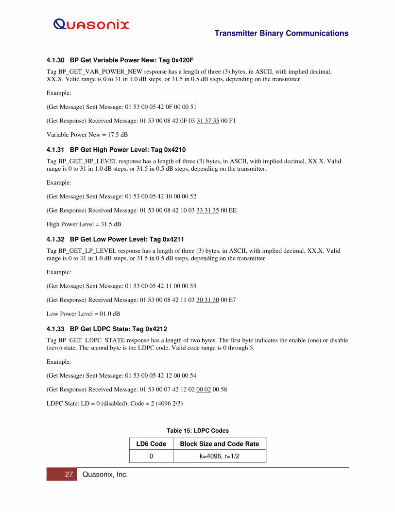
4.1.33 BP Get LDPC State: Tag 0x4212
Tag BP_GET_LDPC_STATE response has a length of two bytes. The first byte indicates the enable (one) or disable
(zero) state. The second byte is the LDPC code. Valid code range is 0 through 5.
Example:
(Get Message) Sent Message: 01 53 00 05 42 12 00 00 54
(Get Response) Received Message: 01 53 00 07 42 12 02 00 02 00 58
LDPC State: LD = 0 (disabled), Code = 2 (4096 2/3)
Table 15: LDPC Codes
LD6 Code Block Size and Code Rate
0 k=4096, r=1/2
Transmitter Binary Communications
28 Quasonix, Inc.
LD6 Code Block Size and Code Rate
1 k=1024, r=1/2
2 k=4096, r=2/3
3 k=1024, r=2/3
4 k=4096, r=4/5
5 k=1024, r=4/5
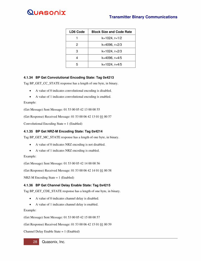
4.1.34 BP Get Convolutional Encoding State: Tag 0x4213
Tag BP_GET_CC_STATE response has a length of one byte, in binary.
• A value of 0 indicates convolutional encoding is disabled.
• A value of 1 indicates convolutional encoding is enabled.
Example:
(Get Message) Sent Message: 01 53 00 05 42 13 00 00 55
(Get Response) Received Message: 01 53 00 06 42 13 01 01 00 57
Convolutional Encoding State = 1 (Enabled)
4.1.35 BP Get NRZ-M Encoding State: Tag 0x4214
Tag BP_GET_MC_STATE response has a length of one byte, in binary.
• A value of 0 indicates NRZ encoding is not disabled.
• A value of 1 indicates NRZ encoding is enabled.
Example:
(Get Message) Sent Message: 01 53 00 05 42 14 00 00 56
(Get Response) Received Message: 01 53 00 06 42 14 01 01 00 58
NRZ-M Encoding State = 1 (Enabled)
4.1.36 BP Get Channel Delay Enable State: Tag 0x4215
Tag BP_GET_CDE_STATE response has a length of one byte, in binary.
• A value of 0 indicates channel delay is disabled.
• A value of 1 indicates channel delay is enabled.
Example:
(Get Message) Sent Message: 01 53 00 05 42 15 00 00 57
(Get Response) Received Message: 01 53 00 06 42 15 01 01 00 59
Channel Delay Enable State = 1 (Enabled)
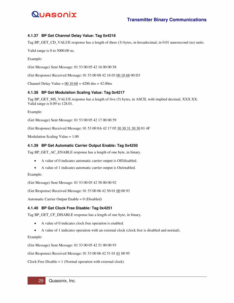
Transmitter Binary Communications
29 Quasonix, Inc.
4.1.37 BP Get Channel Delay Value: Tag 0x4216
Tag BP_GET_CD_VALUE response has a length of three (3) bytes, in hexadecimal, in 0.01 nanosecond (ns) units.
Valid range is 0 to 5000.00 ns.
Example:
(Get Message) Sent Message: 01 53 00 05 42 16 00 00 58
(Get Response) Received Message: 01 53 00 08 42 16 03 00 10 68 00 D3
Channel Delay Value = 00 10 68 = 4200 dns = 42.00ns
4.1.38 BP Get Modulation Scaling Value: Tag 0x4217
Tag BP_GET_MS_VALUE response has a length of five (5) bytes, in ASCII, with implied decimal, XXX.XX.
Valid range is 0.09 to 128.01.
Example:
(Get Message) Sent Message: 01 53 00 05 42 17 00 00 59
(Get Response) Received Message: 01 53 00 0A 42 17 05 30 30 31 30 30 01 4F
Modulation Scaling Value = 1.00
4.1.39 BP Get Automatic Carrier Output Enable: Tag 0x4250
Tag BP_GET_AC_ENABLE response has a length of one byte, in binary.
• A value of 0 indicates automatic carrier output is Off/disabled.
• A value of 1 indicates automatic carrier output is On/enabled.
Example:
(Get Message) Sent Message: 01 53 00 05 42 50 00 00 92
(Get Response) Received Message: 01 53 00 06 42 50 01 00 00 93
Automatic Carrier Output Enable = 0 (Disabled)
4.1.40 BP Get Clock Free Disable: Tag 0x4251
Tag BP_GET_CF_DISABLE response has a length of one byte, in binary.
• A value of 0 indicates clock free operation is enabled.
• A value of 1 indicates operation with an external clock (clock free is disabled and normal).
Example:
(Get Message) Sent Message: 01 53 00 05 42 51 00 00 93
(Get Response) Received Message: 01 53 00 06 42 51 01 01 00 95
Clock Free Disable = 1 (Normal operation with external clock)

Transmitter Binary Communications
30 Quasonix, Inc.
4.1.41 BP Get RF On/Off Pin Polarity State: Tag 0x4252
Tag BP_GET_RZ_STATE response has a length of one byte, in binary.
• A value of 0 indicates RF On when RF On/Off pin is low.
• A value of 1 indicates RF On when RF On/Off pin is high.
Example:
(Get Message) Sent Message: 01 53 00 05 42 52 00 00 94
(Get Response) Received Message: 01 53 00 06 42 52 01 01 00 96
RF On/Off Pin Polarity State (RZ) = 1 (RF On when RF On/Off pin is high)
4.1.42 BP Get Overtemperature Control State: Tag 0x4253
Tag BP_GET_OC_STATE response has a length of one byte, in binary.
• A value of 0 indicates overtemperature control is Off/disabled.
• A value of 1 indicates overtemperature control is On/enabled.
Example:
(Get Message) Sent Message: 01 53 00 05 42 53 00 00 95
(Get Response) Received Message: 01 53 00 06 42 53 01 01 00 97
Overtemperature Control State = 1 (Enabled)
4.1.43 BP Get ASCII Passthrough Enable: Tag 0x4254
Tag BP_GET_BP_PASSTHRU_ENABLE response has a length of one byte, in binary.
• A value of 0 indicates binary protocol passthrough is Off/disabled.
• A value of 1 indicates binary protocol passthrough is On/enabled.
Example:
(Get Message) Sent Message: 01 53 00 05 42 54 00 00 96
(Get Response) Received Message: 01 53 00 06 42 54 01 00 00 97
Binary Protocol Passthrough = 0 (Disabled)
4.1.44 BP Get Temperature: Tag 0x4300
Tag BP_GET_TEMP response has a length of five bytes for single transmitters, or ten bytes for Dual Transmitters,
in ASCII, with implied decimal, XXX.XX. The temperature is in degrees Centigrade.
Example:
(Get Message) Sent Message: 01 53 00 05 43 00 00 00 43
(Get Response) Received Message: 01 53 00 0F 43 00 0A 30 33 39 32 30 30 33 35 30 30 02 43
PA 1 Temperature = 39.20, PA 2 Temperature = 35.00 (Dual Transmitter)
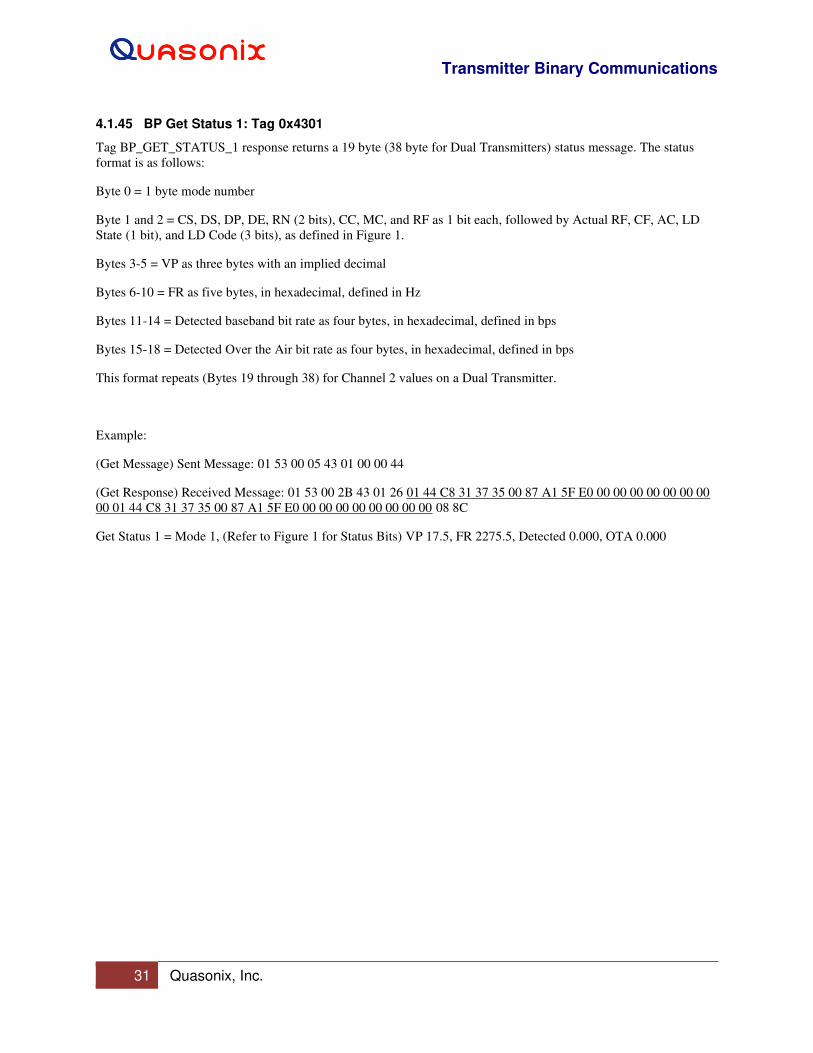
Transmitter Binary Communications
31 Quasonix, Inc.
4.1.45 BP Get Status 1: Tag 0x4301
Tag BP_GET_STATUS_1 response returns a 19 byte (38 byte for Dual Transmitters) status message. The status
format is as follows:
Byte 0 = 1 byte mode number
Byte 1 and 2 = CS, DS, DP, DE, RN (2 bits), CC, MC, and RF as 1 bit each, followed by Actual RF, CF, AC, LD
State (1 bit), and LD Code (3 bits), as defined in Figure 1.
Bytes 3-5 = VP as three bytes with an implied decimal
Bytes 6-10 = FR as five bytes, in hexadecimal, defined in Hz
Bytes 11-14 = Detected baseband bit rate as four bytes, in hexadecimal, defined in bps
Bytes 15-18 = Detected Over the Air bit rate as four bytes, in hexadecimal, defined in bps
This format repeats (Bytes 19 through 38) for Channel 2 values on a Dual Transmitter.
Example:
(Get Message) Sent Message: 01 53 00 05 43 01 00 00 44
(Get Response) Received Message: 01 53 00 2B 43 01 26 01 44 C8 31 37 35 00 87 A1 5F E0 00 00 00 00 00 00 00
00 01 44 C8 31 37 35 00 87 A1 5F E0 00 00 00 00 00 00 00 00 08 8C
Get Status 1 = Mode 1, (Refer to Figure 1 for Status Bits) VP 17.5, FR 2275.5, Detected 0.000, OTA 0.000

Transmitter Binary Communications
32 Quasonix, Inc.
Figure 1: Status 1 Message Bits Example
4.1.46 BP Get Detected Bit Rate: Tag 0x4302
Tag BP_GET_DETECTED_BITRATE response has a length of eight (8) bytes for single channel transmitters, or 16
bytes for Dual Transmitters, in hexadecimal. The first four bytes are the baseband bit rate in bps. The second four
bytes are the Over the Air bit rate in bps.
Example:
(Get Message) Sent Message: 01 53 00 05 43 02 00 00 45
(Get Response) Received Message: 01 53 00 0D 43 02 08 00 4C 4B 4A 00 98 96 95 02 F1
Detected Bit Rate 00 4C 4B 4A = 5000000 bps = 5.000 Mbps
Over the Air Bit Rate = 00 98 96 95 = 10000000 bps = 10.000 Mbps

Transmitter Binary Communications
33 Quasonix, Inc.
4.1.47 BP Get PA Drain Voltage and Current: Tag 0x4303
Tag BP_GET_DRAIN_V_AND_I response has a length of four bytes for single transmitters, or eight bytes for Dual
Transmitters. The first two bytes are the PA drain voltage in mV. The second two bytes are the current in mA.
Example: (using a Dual Transmitter with two channels active)
(Get Message) Sent Message: 01 53 00 05 43 03 00 00 46
(Get Response) Received Message: 01 53 00 0D 43 03 08 28 24 00 1C 26 F0 00 1C 01 E8
PA Drain Voltage, Channel 1 = 10.276 mV, Channel 2 = 9.968 mV;
Current Channel 1 = 0.028 mA, Channel 2 = 0.028 mA
4.1.48 BP Get DTX Channel: Tag 0x4400
Tag BP_DTX_GET_CHANNEL has a length of one byte.
• A value of 0 indicates not a dual transmitter.
• A value of 1 indicates channel 1.
• A value of 2 indicates channel 2.
• A value of 3 indicates channel 1 and channel 2.
Example:
(Get Message) Sent Message: 01 53 00 05 44 00 00 00 44
(Get Response) Received Message: 01 53 00 06 44 00 01 03 00 48
Dual Transmitter Channel = 3
4.2 Get Command Summary
The transmitter information responses are described in Table 30.
Table 16: Transmitter Information Responses
Response Codes Protocol Defines
Description
BP_NAK 0x0001 Corrupt Message (Bad Checksum)
BP_NAK_BAD_ID 0x0002 Bad Device ID
BP_ACK 0x0003 Not Currently Used
BP_UNKNOWN_TAG 0x0004 Unknown TAG in tag field
BP_INVALID_TAG 0x0005 TAG not valid for this mode or device
BP_INVALID_TAG_DATA 0x0006 Data was not valid for this TAG
BP_TAG_LIMIT_EXCEEDED 0x0007 Too many tags in one message
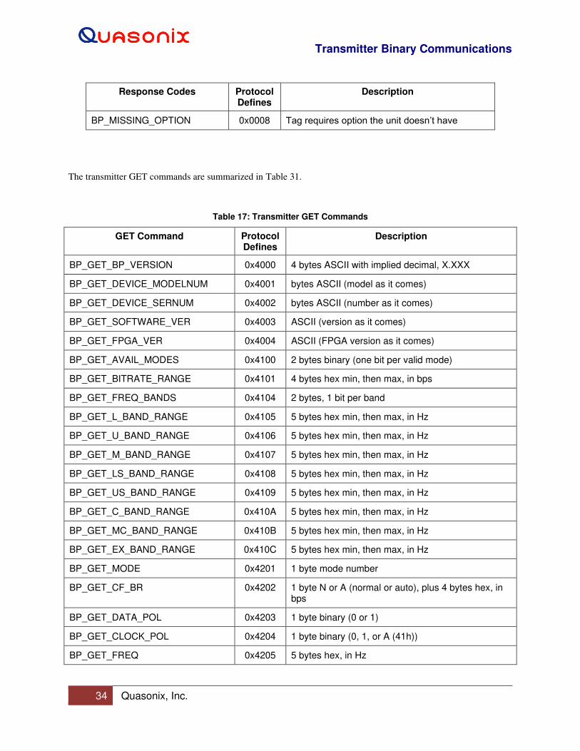
Transmitter Binary Communications
34 Quasonix, Inc.
Response Codes Protocol Defines
Description
BP_MISSING_OPTION 0x0008 Tag requires option the unit doesn’t have
The transmitter GET commands are summarized in Table 31.
Table 17: Transmitter GET Commands
GET Command Protocol Defines
Description
BP_GET_BP_VERSION 0x4000 4 bytes ASCII with implied decimal, X.XXX
BP_GET_DEVICE_MODELNUM 0x4001 bytes ASCII (model as it comes)
BP_GET_DEVICE_SERNUM 0x4002 bytes ASCII (number as it comes)
BP_GET_SOFTWARE_VER 0x4003 ASCII (version as it comes)
BP_GET_FPGA_VER 0x4004 ASCII (FPGA version as it comes)
BP_GET_AVAIL_MODES 0x4100 2 bytes binary (one bit per valid mode)
BP_GET_BITRATE_RANGE 0x4101 4 bytes hex min, then max, in bps
BP_GET_FREQ_BANDS 0x4104 2 bytes, 1 bit per band
BP_GET_L_BAND_RANGE 0x4105 5 bytes hex min, then max, in Hz
BP_GET_U_BAND_RANGE 0x4106 5 bytes hex min, then max, in Hz
BP_GET_M_BAND_RANGE 0x4107 5 bytes hex min, then max, in Hz
BP_GET_LS_BAND_RANGE 0x4108 5 bytes hex min, then max, in Hz
BP_GET_US_BAND_RANGE 0x4109 5 bytes hex min, then max, in Hz
BP_GET_C_BAND_RANGE 0x410A 5 bytes hex min, then max, in Hz
BP_GET_MC_BAND_RANGE 0x410B 5 bytes hex min, then max, in Hz
BP_GET_EX_BAND_RANGE 0x410C 5 bytes hex min, then max, in Hz
BP_GET_MODE 0x4201 1 byte mode number
BP_GET_CF_BR 0x4202 1 byte N or A (normal or auto), plus 4 bytes hex, in bps
BP_GET_DATA_POL 0x4203 1 byte binary (0 or 1)
BP_GET_CLOCK_POL 0x4204 1 byte binary (0, 1, or A (41h))
BP_GET_FREQ 0x4205 5 bytes hex, in Hz
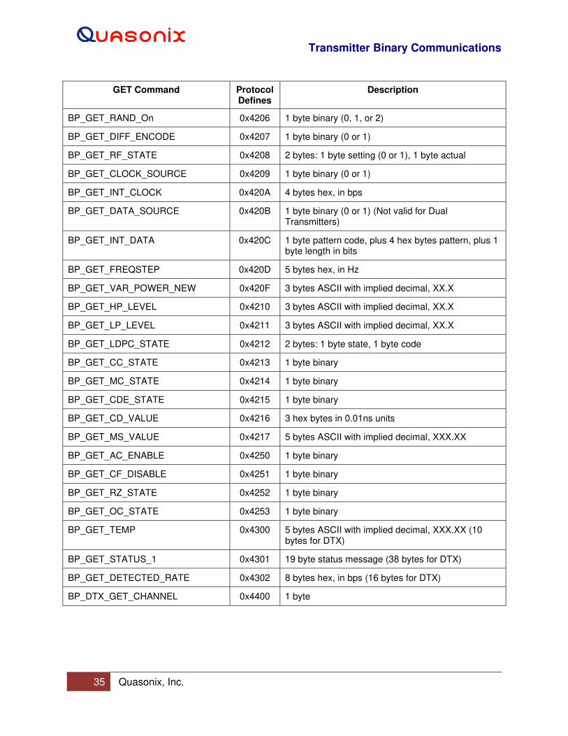
Transmitter Binary Communications
35 Quasonix, Inc.
GET Command Protocol Defines
Description
BP_GET_RAND_On 0x4206 1 byte binary (0, 1, or 2)
BP_GET_DIFF_ENCODE 0x4207 1 byte binary (0 or 1)
BP_GET_RF_STATE 0x4208 2 bytes: 1 byte setting (0 or 1), 1 byte actual
BP_GET_CLOCK_SOURCE 0x4209 1 byte binary (0 or 1)
BP_GET_INT_CLOCK 0x420A 4 bytes hex, in bps
BP_GET_DATA_SOURCE 0x420B 1 byte binary (0 or 1) (Not valid for Dual Transmitters)
BP_GET_INT_DATA 0x420C 1 byte pattern code, plus 4 hex bytes pattern, plus 1 byte length in bits
BP_GET_FREQSTEP 0x420D 5 bytes hex, in Hz
BP_GET_VAR_POWER_NEW 0x420F 3 bytes ASCII with implied decimal, XX.X
BP_GET_HP_LEVEL 0x4210 3 bytes ASCII with implied decimal, XX.X
BP_GET_LP_LEVEL 0x4211 3 bytes ASCII with implied decimal, XX.X
BP_GET_LDPC_STATE 0x4212 2 bytes: 1 byte state, 1 byte code
BP_GET_CC_STATE 0x4213 1 byte binary
BP_GET_MC_STATE 0x4214 1 byte binary
BP_GET_CDE_STATE 0x4215 1 byte binary
BP_GET_CD_VALUE 0x4216 3 hex bytes in 0.01ns units
BP_GET_MS_VALUE 0x4217 5 bytes ASCII with implied decimal, XXX.XX
BP_GET_AC_ENABLE 0x4250 1 byte binary
BP_GET_CF_DISABLE 0x4251 1 byte binary
BP_GET_RZ_STATE 0x4252 1 byte binary
BP_GET_OC_STATE 0x4253 1 byte binary
BP_GET_TEMP 0x4300 5 bytes ASCII with implied decimal, XXX.XX (10 bytes for DTX)
BP_GET_STATUS_1 0x4301 19 byte status message (38 bytes for DTX)
BP_GET_DETECTED_RATE 0x4302 8 bytes hex, in bps (16 bytes for DTX)
BP_DTX_GET_CHANNEL 0x4400 1 byte
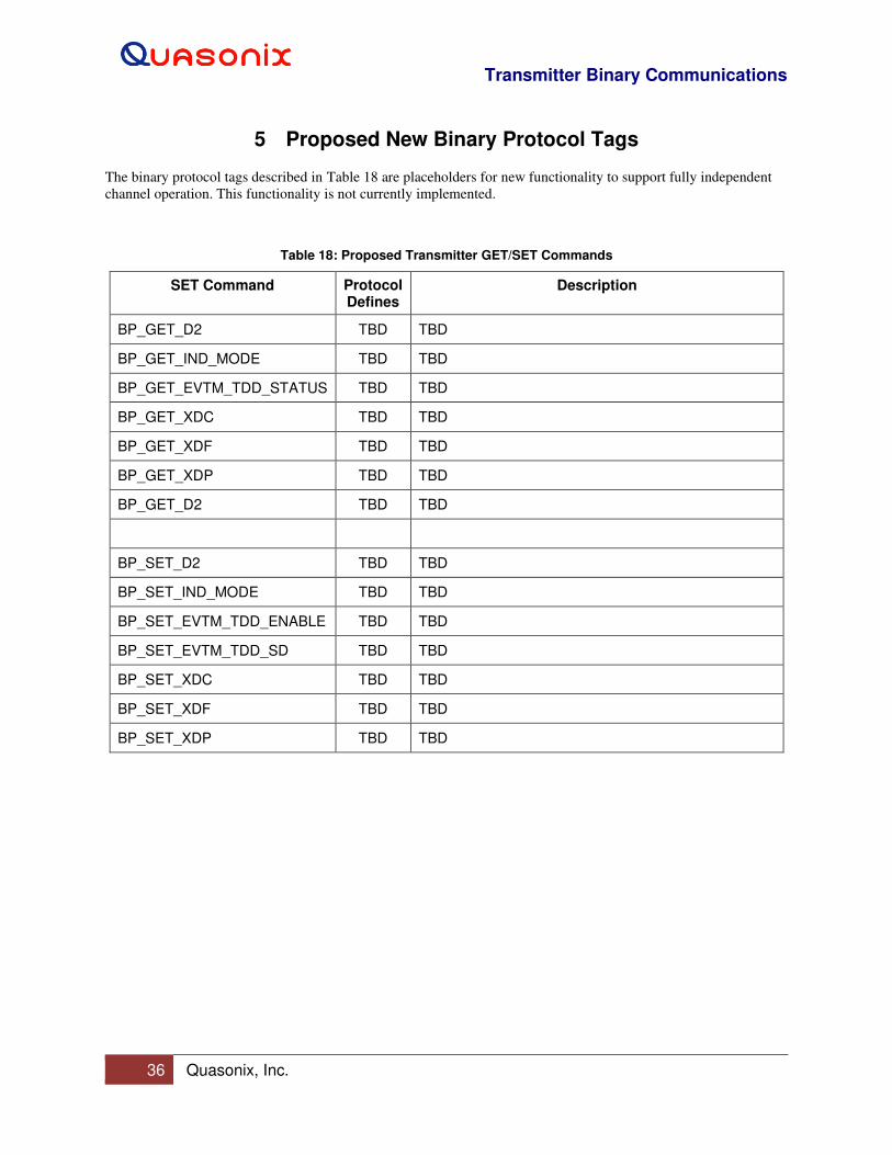
Transmitter Binary Communications
36 Quasonix, Inc.
5 Proposed New Binary Protocol Tags
The binary protocol tags described in Table 18 are placeholders for new functionality to support fully independent
channel operation. This functionality is not currently implemented.
Table 18: Proposed Transmitter GET/SET Commands
SET Command Protocol Defines
Description
BP_GET_D2 TBD TBD
BP_GET_IND_MODE TBD TBD
BP_GET_EVTM_TDD_STATUS TBD TBD
BP_GET_XDC TBD TBD
BP_GET_XDF TBD TBD
BP_GET_XDP TBD TBD
BP_GET_D2 TBD TBD
BP_SET_D2 TBD TBD
BP_SET_IND_MODE TBD TBD
BP_SET_EVTM_TDD_ENABLE TBD TBD
BP_SET_EVTM_TDD_SD TBD TBD
BP_SET_XDC TBD TBD
BP_SET_XDF TBD TBD
BP_SET_XDP TBD TBD
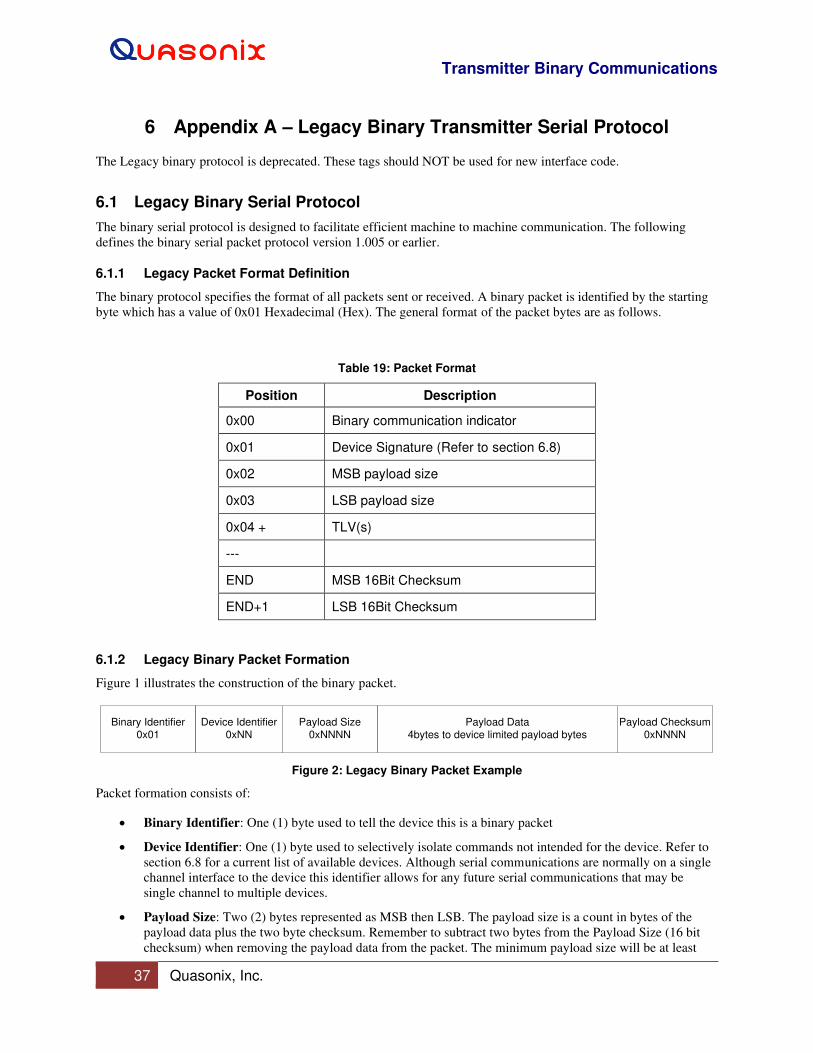
Transmitter Binary Communications
37 Quasonix, Inc.
6 Appendix A – Legacy Binary Transmitter Serial Protocol
The Legacy binary protocol is deprecated. These tags should NOT be used for new interface code.
6.1 Legacy Binary Serial Protocol
The binary serial protocol is designed to facilitate efficient machine to machine communication. The following
defines the binary serial packet protocol version 1.005 or earlier.
6.1.1 Legacy Packet Format Definition
The binary protocol specifies the format of all packets sent or received. A binary packet is identified by the starting
byte which has a value of 0x01 Hexadecimal (Hex). The general format of the packet bytes are as follows.
Table 19: Packet Format
Position Description
0x00 Binary communication indicator
0x01 Device Signature (Refer to section 6.8)
0x02 MSB payload size
0x03 LSB payload size
0x04 + TLV(s)
---
END MSB 16Bit Checksum
END+1 LSB 16Bit Checksum
6.1.2 Legacy Binary Packet Formation
Figure 1 illustrates the construction of the binary packet.
Binary Identifier
0x01
Device Identifier
0xNN
Payload Size
0xNNNN
Payload Data
4bytes to device limited payload bytes
Payload Checksum
0xNNNN
Figure 2: Legacy Binary Packet Example
Packet formation consists of:
• Binary Identifier: One (1) byte used to tell the device this is a binary packet
• Device Identifier: One (1) byte used to selectively isolate commands not intended for the device. Refer to
section 6.8 for a current list of available devices. Although serial communications are normally on a single
channel interface to the device this identifier allows for any future serial communications that may be
single channel to multiple devices.
• Payload Size: Two (2) bytes represented as MSB then LSB. The payload size is a count in bytes of the
payload data plus the two byte checksum. Remember to subtract two bytes from the Payload Size (16 bit
checksum) when removing the payload data from the packet. The minimum payload size will be at least

Transmitter Binary Communications
38 Quasonix, Inc.
four (4) bytes. This minimum is determined by the smallest TLV command size. The maximum payload
size is limited by the device.
• Payload Data: Payload data is one or more TLV commands of variable length. The smallest Payload Data
size will be at least one TLV command or four (4) bytes.
• Payload Checksum: Two (2) bytes represent the Payload Checksum. The Payload Checksum is calculated
by adding the actual value of each byte of the Payload Data. When calculating the Payload Checksum in
software an unsigned 16 bit variable should be used. This allows for the rollover of the variable when the
calculation exceeds its maximum 0xFFFF value.
Note: This calculation includes the Payload Data only.
6.1.3 Receiving a Legacy Binary Packet from the Device
To receive binary serial packets on a single threaded operating system, it is recommended that an interrupt driven
serial routine be used. For multitasking operating systems, a blocking thread is recommended.
The interrupt or blocking thread should wait for received data on the serial port. When the first byte of data begins to
be received on the serial port, the software should start a binary packet watchdog timer. With the watchdog timer
started, the data buffer may be polled to see if more than four bytes have been received (the minimum packet size to
acquire the payload size). After a minimum of four bytes have been received, the packet may be parsed for the
payload size. With the payload size parsed, the software may continue to poll until the actual payload received
matches the reported Payload Size. In time critical systems, the polling can be adjusted based on the baud and
reported payload size. For most cases, a simple polling until the received payload matches the reported payload
works fine. The watchdog timer should go off if the expected binary packet has not been received in an expected
timeframe. The watchdog should have enough time to receive the entire packet plus some extra time for any
possible transmission delays from the device.
6.1.4 Legacy Binary Packet Errors
There are two conditions in which the binary packet may be checked for errors.
• The first condition is a mismatch of the actual received payload size with the Payload Size reported in the
packet. If these two sizes do not match and the binary packet watchdog has waited for enough time to
receive the reported size of the packet, then the packet should be considered corrupt and a retry or a timeout
condition should be considered.
• The second condition is the Payload Checksum. If the calculated Payload Checksum does not match the
received Payload Checksum, then the packet should be considered corrupt and a retry or a timeout
condition should be considered.
6.1.5 Legacy TLV Commands - Payload Data
6.1.5.1 Legacy TLV Data Information
TLV is an acronym for: Tag, Length, and Variable.
• Tag - Tag consists of two bytes and forms the command. (65535 or 0xFFFF Hex possible TAG commands)
• Length - Length consists of one byte. The length indicates how many bytes will be used for the Tag
command data variable with a maximum variable size of 255 or 0xFF Hex bytes.
• Variable - Variable is the actual data associated with the Tag. Depending on the Tag, the variable may be
binary data that forms an ASCII string or the actual binary value which represents the tags value.
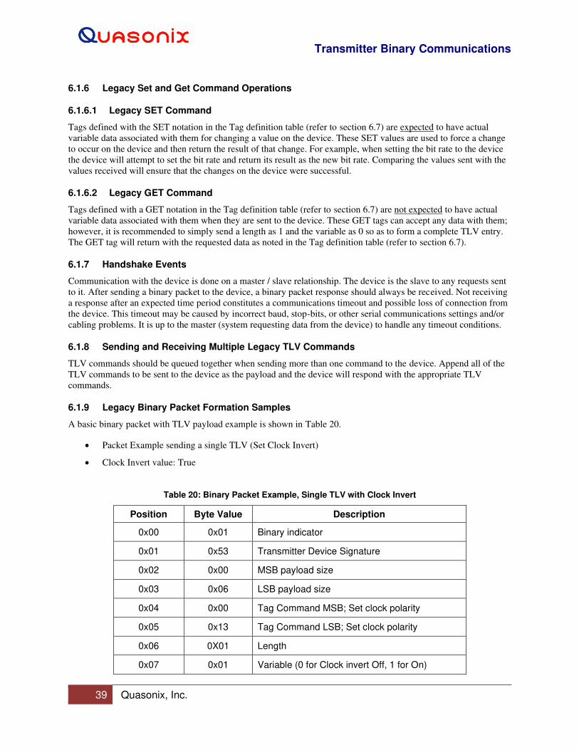
Transmitter Binary Communications
39 Quasonix, Inc.
6.1.6 Legacy Set and Get Command Operations
6.1.6.1 Legacy SET Command
Tags defined with the SET notation in the Tag definition table (refer to section 6.7) are expected to have actual
variable data associated with them for changing a value on the device. These SET values are used to force a change
to occur on the device and then return the result of that change. For example, when setting the bit rate to the device
the device will attempt to set the bit rate and return its result as the new bit rate. Comparing the values sent with the
values received will ensure that the changes on the device were successful.
6.1.6.2 Legacy GET Command
Tags defined with a GET notation in the Tag definition table (refer to section 6.7) are not expected to have actual
variable data associated with them when they are sent to the device. These GET tags can accept any data with them;
however, it is recommended to simply send a length as 1 and the variable as 0 so as to form a complete TLV entry.
The GET tag will return with the requested data as noted in the Tag definition table (refer to section 6.7).
6.1.7 Handshake Events
Communication with the device is done on a master / slave relationship. The device is the slave to any requests sent
to it. After sending a binary packet to the device, a binary packet response should always be received. Not receiving
a response after an expected time period constitutes a communications timeout and possible loss of connection from
the device. This timeout may be caused by incorrect baud, stop-bits, or other serial communications settings and/or
cabling problems. It is up to the master (system requesting data from the device) to handle any timeout conditions.
6.1.8 Sending and Receiving Multiple Legacy TLV Commands
TLV commands should be queued together when sending more than one command to the device. Append all of the
TLV commands to be sent to the device as the payload and the device will respond with the appropriate TLV
commands.
6.1.9 Legacy Binary Packet Formation Samples
A basic binary packet with TLV payload example is shown in Table 20.
• Packet Example sending a single TLV (Set Clock Invert)
• Clock Invert value: True
Table 20: Binary Packet Example, Single TLV with Clock Invert
Position Byte Value Description
0x00 0x01 Binary indicator
0x01 0x53 Transmitter Device Signature
0x02 0x00 MSB payload size
0x03 0x06 LSB payload size
0x04 0x00 Tag Command MSB; Set clock polarity
0x05 0x13 Tag Command LSB; Set clock polarity
0x06 0X01 Length
0x07 0x01 Variable (0 for Clock invert Off, 1 for On)

Transmitter Binary Communications
40 Quasonix, Inc.
Position Byte Value Description
0x08 0x00 Checksum MSB
0x09 0x15 Checksum LSB
A packet example sending a single TLV command with multiple data bytes represented as ASCII data (Set Freq) is
shown in Table 21.
• Frequency Value: 2200.5 MHz
Table 21: Binary Packet Example, Single TLV, Multiple Bytes as ASCII Data
Position Byte Value Description
0x00 0x01 Binary Start of Message indicator
0x01 0x53 Transmitter Device Signature
0x02 0x00 MSB payload size
0x03 0x10 LSB payload size
0x04 0x00 Tag Command MSB; Set frequency
0x05 0x17 Tag Command LSB; Set frequency
0x06 0X0B Length
0x07 0x32 Variable data. “2”
0x08 0x32 Variable data. “2”
0x09 0x30 Variable data. “0”
0x0A 0x30 Variable data. “0”
0x0B 0x2E Variable data. “.”
0x0C 0x35 Variable data. “5”
0x0D 0x30 Variable data. “0”
0x0E 0x30 Variable data. “0”
0x0F 0x30 Variable data. “0”
0x10 0x30 Variable data. “0”
0x11 0x30 Variable data. “0”
0x12 0x02 Checksum MSB
0x13 0x39 Checksum LSB
Transmitter Binary Communications
41 Quasonix, Inc.
6.2 Legacy Information Response Tags
6.2.1 NAK: Tag 0x0001
This response indicates that the device received a corrupt message or timed out. None of the received tags could be
processed by the device.
NAK = 0x0001; // (L)= 0 bytes(V)=0x00~0x00 (Binary)
6.2.2 NAK Bad ID: Tag 0x0002
This response indicates that the device ID does not match the device. None of the received tags could be processed
by the device.
NAK_BAD_ID = 0x0002; // (L)= 0 bytes(V)=0x00~0x00 (Binary)
6.2.3 ACK: Tag 0x0003
This response is not currently in use.
ACK = 0x0003; // (L)= 0 bytes(V)=0x00~0x00 (Binary)
6.2.4 Unknown TAG: Tag 0x0004
This response indicates that the device received an unknown tag. Older devices may not support the given tag and
this response will be returned. If more than one tag was sent to the device, then the remaining tags will be processed.
Unknown Tag will also return with two bytes that contain the tag that was not known.
UNKNOWN_TAG = 0x0004; // (L)= 2 bytes(V)=0x00~0xFF (Binary)
6.2.5 Invalid TAG: Tag 0x0005
This response indicates that the device understood the tag but found that it was not valid for the active mode or
device itself. This message may be a common response if you decide to always send a set of commands to the
device regardless of the mode the device is set to. An example of this is setting differential encoding while the
device is in PCMFM since differential encoding is only valid for SOQPSK. If more than one tag was sent to the
device, then the remaining tags will be processed. Invalid Tag will also return with two bytes that contain the tag
that the device found to be invalid.
INVALID_TAG = 0x0005; // (L)= 2 bytes(V)=0x00~0xFF (Binary)
6.2.6 Invalid TAG Data: Tag 0x0006
This response indicates that the device understood the tag but found that the data was not valid for the given tag.
This error may occur if a tag that was supposed to have a data length of 1 byte received 2 bytes for the tag variable.
If more than one tag was sent to the device then the remaining tags will be processed. Invalid Tag data will also
return with two bytes that contain the tag that had bad data.
INVALID_TAG_DATA = 0x0006; // (L)= 2 bytes(V)=0x00~0xFF (Binary)
6.2.7 Tag Limit Exceeded: Tag 0x0007
This response indicates that the device exceeded its capacity to process any more tags. Tags up to this tag on a
response were processed; any additional tags were not.
TAG_LIMIT_EXCEEDED = 0x0007; // (L)= 0 bytes(V)=0x00~0x00 (Binary)
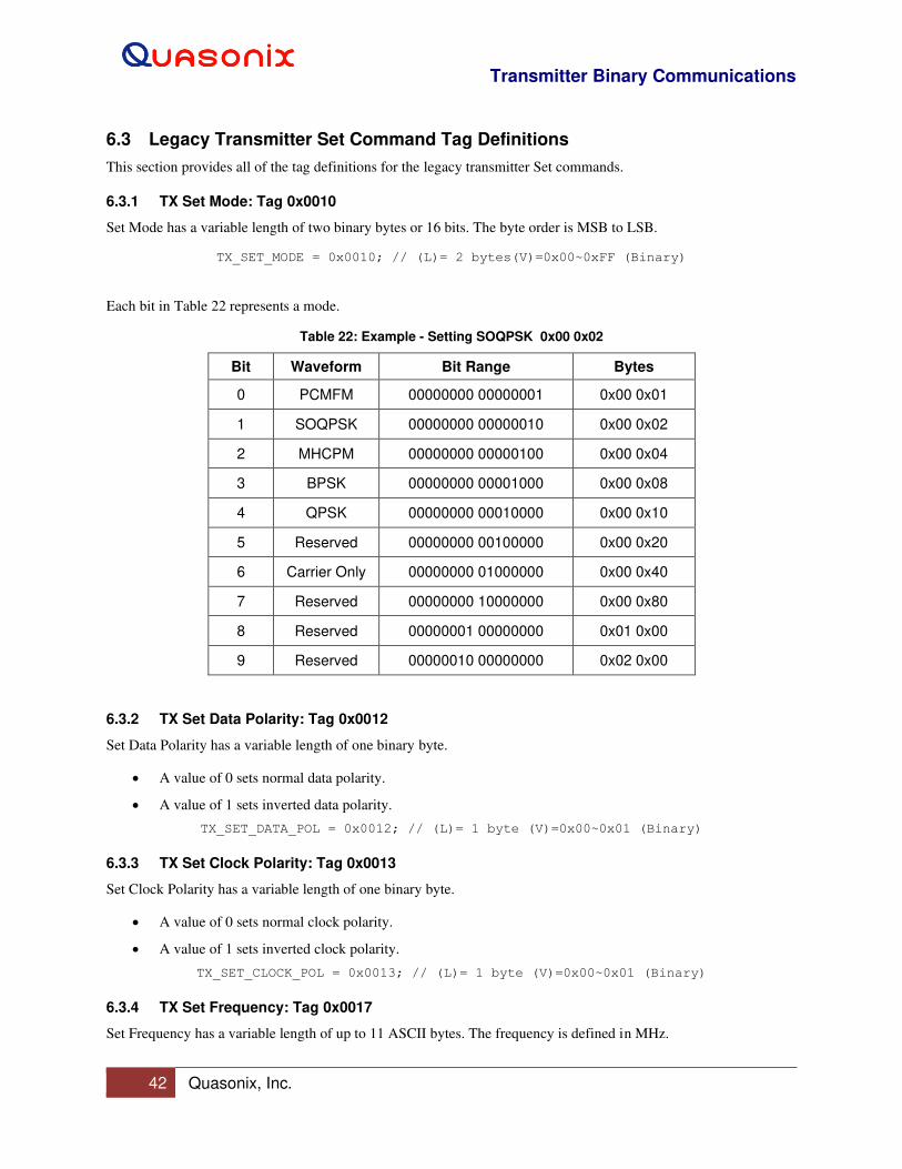
Transmitter Binary Communications
42 Quasonix, Inc.
6.3 Legacy Transmitter Set Command Tag Definitions
This section provides all of the tag definitions for the legacy transmitter Set commands.
6.3.1 TX Set Mode: Tag 0x0010
Set Mode has a variable length of two binary bytes or 16 bits. The byte order is MSB to LSB.
TX_SET_MODE = 0x0010; // (L)= 2 bytes(V)=0x00~0xFF (Binary)
Each bit in Table 22 represents a mode.
Table 22: Example - Setting SOQPSK 0x00 0x02
Bit Waveform Bit Range Bytes
0 PCMFM 00000000 00000001 0x00 0x01
1 SOQPSK 00000000 00000010 0x00 0x02
2 MHCPM 00000000 00000100 0x00 0x04
3 BPSK 00000000 00001000 0x00 0x08
4 QPSK 00000000 00010000 0x00 0x10
5 Reserved 00000000 00100000 0x00 0x20
6 Carrier Only 00000000 01000000 0x00 0x40
7 Reserved 00000000 10000000 0x00 0x80
8 Reserved 00000001 00000000 0x01 0x00
9 Reserved 00000010 00000000 0x02 0x00
6.3.2 TX Set Data Polarity: Tag 0x0012
Set Data Polarity has a variable length of one binary byte.
• A value of 0 sets normal data polarity.
• A value of 1 sets inverted data polarity.
TX_SET_DATA_POL = 0x0012; // (L)= 1 byte (V)=0x00~0x01 (Binary)
6.3.3 TX Set Clock Polarity: Tag 0x0013
Set Clock Polarity has a variable length of one binary byte.
• A value of 0 sets normal clock polarity.
• A value of 1 sets inverted clock polarity.
TX_SET_CLOCK_POL = 0x0013; // (L)= 1 byte (V)=0x00~0x01 (Binary)
6.3.4 TX Set Frequency: Tag 0x0017
Set Frequency has a variable length of up to 11 ASCII bytes. The frequency is defined in MHz.
Transmitter Binary Communications
43 Quasonix, Inc.
Example: 1450.0
TX_SET_FREQ = 0x0017; // (L)= 11 bytes(V)=0x00~0xFF (ASCII)
6.3.5 TX Set Randomizer: Tag 0x2015
Set Randomizer has a variable length of one binary byte.
• A value of 0 sets randomizer Off.
• A value of 1 sets randomizer On.
TX_SET_RAND_On = 0x2015; // (L)= 1 byte (V)=0x00~0x01 (Binary)
6.3.6 TX Set Differential Encoding: Tag 0x0019
Set Differential Encoding has a variable length of one binary byte and only applies to SOQPSK mode. On is the
default setting for differential encoding when in SOQPSK mode.
• A value of 0 sets differential Off.
• A value of 1 set differential On.
TX_SET_DIFF_ENCODE = 0x0019; // (L)= 1 byte (V)=0x00~0x01 (Binary)
6.3.7 TX Set RF On: Tag 0x2018
Set RF On has a variable length of one binary byte.
• A value of 0 sets RF output Off.
• A value of 1 sets RF output On.
TX_SET_RF_On = 0x2018; // (L)= 1 byte (V)=0x00~0x01 (Binary)
6.3.8 TX Set Clock Source: Tag 0x2019
Set Clock Source has a variable length of one binary byte.
• A value of 0 sets clock source to external.
• A value of 1 sets clock source to internal.
TX_SET_CLOCK_SOURCE = 0x2019; // (L)= 1 byte (V)=0x00~0x01 (Binary)
6.3.9 TX Set Internal Clock: Tag 0x201A
Set Internal Clock has a variable length of up to 11 ASCII bytes. The frequency is defined in MHz. Specified clock
rates are rounded to the nearest integer multiple of 93.333 / 65536 MHz (approximately 1424.15 Hz).
Example: 4.95
• Valid range is 0.150 MHz – 22.0 MHz
TX_SET_INT_CLOCK = 0x201A; // (L)= 11 bytes(V)=0x00~0xFF (ASCII) MHz
6.3.10 TX Set Data Source: Tag 0x201B
Set Data Source has a variable length of one binary byte.
• A value of 0 indicates data source is external.
• A value of 1 indicates data source is internal.
Transmitter Binary Communications
44 Quasonix, Inc.
TX_SET_DATA_SOURCE = 0x201B; // (L)= 1 byte (V)=0x00~0x01 (Binary)
6.3.11 TX Set Internal Data: Tag 0x201C
Set Internal Data has a variable length of three binary bytes MSB to LSB. The first byte (MSB) indicates one of the
following standard patterns:
PN6_PATTERN = 0x00; PN06_PATTERN = 0x01; PN11_PATTERN = 0x02; PN15_PATTERN = 0x03; PN23_PATTERN = 0x04; USER_PATTERN = 0x05;
The last two bytes indicate a custom user pattern.
Example: 0x05 0xAA 0x55
Sets custom user pattern to 0xaa55
TX_SET_INT_DATA = 0x201C; // (L)= 3 bytes as pattern code or value (Binary)
6.3.12 TX Set Variable Power: Tag 0x201D
Set Variable Power has a variable length of one binary byte. Not all devices support this tag.
• Valid ranges are from 0x00 to 0x1F.
TX_SET_VAR_POWER = 0x201D; // (L)= 1 byte (V)=0x00~0x01 (Binary)
6.3.13 TX Set Variable Power New: Tag 0x201E
Set Variable Power New has a variable length of four binary bytes. Not all devices support this tag.
• Valid ranges are from 00.0 to 31.5.
TX_SET_VAR_POWER_NEW = 0x201E; // (L)= 4 bytes (V)=0x00~0x01??? (ASCII)
6.3.14 TX Save Command: Tag 0x0040
TX Save has a variable length of one binary byte. Transmitter devices have up to eight save profile settings. Save
profile 0 is used to save the profile that the device will configure to after a power cycle.
TX_SAVE_CMD = 0x0040; // (L)= 1 byte (V)=0x00~0x08 (Binary)
6.4 Legacy Set Command Summary
The legacy transmitter information responses are described in Table 23.
Table 23: Legacy Transmitter Information Responses
Response Codes Protocol Defines
Description
NAK 0x0001 Corrupt Message (Bad Checksum)
NAK_BAD_ID 0x0002 Bad Device ID
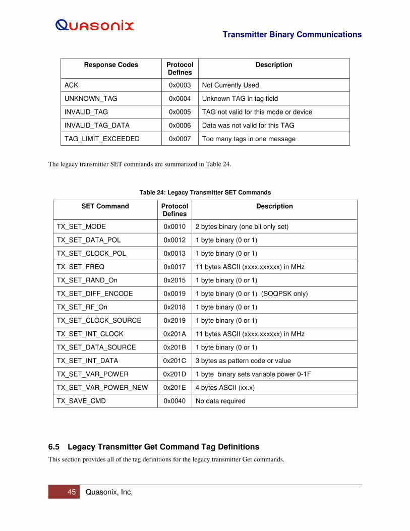
Transmitter Binary Communications
45 Quasonix, Inc.
Response Codes Protocol Defines
Description
ACK 0x0003 Not Currently Used
UNKNOWN_TAG 0x0004 Unknown TAG in tag field
INVALID_TAG 0x0005 TAG not valid for this mode or device
INVALID_TAG_DATA 0x0006 Data was not valid for this TAG
TAG_LIMIT_EXCEEDED 0x0007 Too many tags in one message
The legacy transmitter SET commands are summarized in Table 24.
Table 24: Legacy Transmitter SET Commands
SET Command Protocol Defines
Description
TX_SET_MODE 0x0010 2 bytes binary (one bit only set)
TX_SET_DATA_POL 0x0012 1 byte binary (0 or 1)
TX_SET_CLOCK_POL 0x0013 1 byte binary (0 or 1)
TX_SET_FREQ 0x0017 11 bytes ASCII (xxxx.xxxxxx) in MHz
TX_SET_RAND_On 0x2015 1 byte binary (0 or 1)
TX_SET_DIFF_ENCODE 0x0019 1 byte binary (0 or 1) (SOQPSK only)
TX_SET_RF_On 0x2018 1 byte binary (0 or 1)
TX_SET_CLOCK_SOURCE 0x2019 1 byte binary (0 or 1)
TX_SET_INT_CLOCK 0x201A 11 bytes ASCII (xxxx.xxxxxx) in MHz
TX_SET_DATA_SOURCE 0x201B 1 byte binary (0 or 1)
TX_SET_INT_DATA 0x201C 3 bytes as pattern code or value
TX_SET_VAR_POWER 0x201D 1 byte binary sets variable power 0-1F
TX_SET_VAR_POWER_NEW 0x201E 4 bytes ASCII (xx.x)
TX_SAVE_CMD 0x0040 No data required
6.5 Legacy Transmitter Get Command Tag Definitions
This section provides all of the tag definitions for the legacy transmitter Get commands.

Transmitter Binary Communications
46 Quasonix, Inc.
6.5.1 TX Get Mode: Tag 0x0090
Get Mode has a variable length of two binary bytes or 16 bits. Each bit represents a mode, as described in Table 25.
The byte order is MSB to LSB.
Example: Value returned is 0x00 0x02 (mode is SOQPSK).
TX_GET_MODE = 0x0090; // (L)= 2 bytes(V)=0x00~0xFF (Binary)
Table 25: TX Get Mode Bit Descriptions
Bit Waveform Bit Range Bytes
0 PCMFM (bits 00000000 00000001) 0x00 0x01
1 SOQPSK (bits 00000000 00000010) 0x00 0x02
2 MHCPM (bits 00000000 00000100) 0x00 0x04
3 BPSK (bits 00000000 00001000) 0x00 0x08
4 QPSK (bits 00000000 00010000) 0x00 0x10
5 Reserved (bits 00000000 00100000) 0x00 0x20
6 Carrier Only (bits 00000000 01000000) 0x00 0x40
7 Reserved (bits 00000000 10000000) 0x00 0x80
8 Reserved (bits 00000001 00000000) 0x01 0x00
9 Reserved (bits 00000010 00000000) 0x02 0x00
6.5.2 TX_Get Data Polarity: Tag 0x0092
Get Data Polarity has a variable length of one binary byte.
• A value of 0 indicates normal data polarity.
• A value of 1 indicates inverted data polarity.
TX_GET_DATA_POL = 0x0092; // (L)= 1 byte (V)=0x00~0x01 (Binary)
6.5.3 TX_Get Clock Polarity: Tag 0x0093
Get Clock Polarity has a variable length of one binary byte.
• A value of 0 indicates normal clock polarity.
• A value of 1 indicates inverted clock polarity.
TX_GET_CLOCK_POL = 0x0093; // (L)= 1 byte (V)=0x00~0x01 (Binary)
6.5.4 TX Get Frequency: Tag 0x0097
Get Frequency has a variable length of up to 11 ASCII bytes. The frequency is defined in MHz. This variable is
returned as an ASCII string stored in multiple bytes.
Example: Bytes returned (0x31 0x314 0x35 0x30 0x2E 0x30)
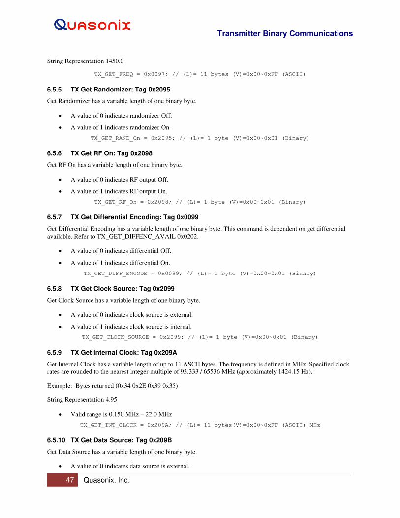
Transmitter Binary Communications
47 Quasonix, Inc.
String Representation 1450.0
TX_GET_FREQ = 0x0097; // (L)= 11 bytes (V)=0x00~0xFF (ASCII)
6.5.5 TX Get Randomizer: Tag 0x2095
Get Randomizer has a variable length of one binary byte.
• A value of 0 indicates randomizer Off.
• A value of 1 indicates randomizer On.
TX_GET_RAND_On = 0x2095; // (L)= 1 byte (V)=0x00~0x01 (Binary)
6.5.6 TX Get RF On: Tag 0x2098
Get RF On has a variable length of one binary byte.
• A value of 0 indicates RF output Off.
• A value of 1 indicates RF output On.
TX_GET_RF_On = 0x2098; // (L)= 1 byte (V)=0x00~0x01 (Binary)
6.5.7 TX Get Differential Encoding: Tag 0x0099
Get Differential Encoding has a variable length of one binary byte. This command is dependent on get differential
available. Refer to TX_GET_DIFFENC_AVAIL 0x0202.
• A value of 0 indicates differential Off.
• A value of 1 indicates differential On.
TX_GET_DIFF_ENCODE = 0x0099; // (L)= 1 byte (V)=0x00~0x01 (Binary)
6.5.8 TX Get Clock Source: Tag 0x2099
Get Clock Source has a variable length of one binary byte.
• A value of 0 indicates clock source is external.
• A value of 1 indicates clock source is internal.
TX_GET_CLOCK_SOURCE = 0x2099; // (L)= 1 byte (V)=0x00~0x01 (Binary)
6.5.9 TX Get Internal Clock: Tag 0x209A
Get Internal Clock has a variable length of up to 11 ASCII bytes. The frequency is defined in MHz. Specified clock
rates are rounded to the nearest integer multiple of 93.333 / 65536 MHz (approximately 1424.15 Hz).
Example: Bytes returned (0x34 0x2E 0x39 0x35)
String Representation 4.95
• Valid range is 0.150 MHz – 22.0 MHz
TX_GET_INT_CLOCK = 0x209A; // (L)= 11 bytes(V)=0x00~0xFF (ASCII) MHz
6.5.10 TX Get Data Source: Tag 0x209B
Get Data Source has a variable length of one binary byte.
• A value of 0 indicates data source is external.

Transmitter Binary Communications
48 Quasonix, Inc.
• A value of 1 indicates data source is internal.
TX_GET_DATA_SOURCE = 0x209B; // (L)= 1 byte (V)=0x00~0x01 (Binary)
6.5.11 TX Get Internal Data: Tag 0x209C
Get Internal Data has a variable length of three binary bytes, MSB to LSB. The first byte (MSB) indicates one of the
following standard patterns:
PN6_PATTERN = 0x00; PN06_PATTERN = 0x01; PN11_PATTERN = 0x02; PN15_PATTERN = 0x03; PN23_PATTERN = 0x04; USER_PATTERN = 0x05;
The last two bytes indicate a custom user pattern.
TX_GET_INT_DATA = 0x209C; // (L)= 3 bytes as pattern code or value (Binary)
6.5.12 TX Get Temperature: Tag 0x009A
Get Temperature has a variable length of up to six ASCII bytes. The temperature is defined in degrees C. This
variable is returned as an ASCII string stored in multiple bytes. The format is xxx.xx where the leading character is
a space, - sign (negative), or a number.
Example: Bytes returned (0x20 0x33 0x37 0x2E 0x30 0x30)
String Representation: _37.00, -25.20, 112.10, _-9.10, _ _7.01
TX_GET_TEMP = 0x009A; // (L)= 6 bytes ASCII (xxx.xx in Deg C)
6.5.13 TX Get Variable Power: Tag 0x221D
Get Variable Power has a variable length of one binary byte.
• Valid ranges are from 0x00 to 0x1F.
TX_GET_VAR_POWER = 0x221D; // (L)= 1 byte (0 to 0x1F) (Binary)
6.5.14 TX Get Variable Power New: Tag 0x221E
Get Variable Power New has a length of four ASCII bytes.
TX_GET_VAR_POWER_NEW = 0x221E; // (L)= 4 bytes ASCII
6.5.15 TX Get Device Serial Number: Tag 0x0101
Get Device Serial Number has a length of ten ASCII bytes.
Example: “_ _ _ _ _ _1009”
TX_GET_DEVICE_SERNUM = 0x0101; // (L)= 10 bytes ASCII
6.5.16 TX Get Available Modes: Tag 0x0102
Get Available Modes has a variable length of two binary bytes. Each mode is one bit, as shown in Table 26.
TX_GET_AVAIL_MODES = 0x0102; // (L)= 2 bytes (V)

Transmitter Binary Communications
49 Quasonix, Inc.
Table 26: TX Get Available Modes Bit Descriptions
Bit Command Name Protocol Defines
Waveform (Mode) Description
BP_PCMFM_MODE_BIT 0x0001 PCMFM
BP_SOQPSK_MODE_BIT 0x0002 SOQPSK
BP_MHCPM_MODE_BIT 0x0004 MHCPM
BP_BPSK_MODE_BIT 0x0008 BPSK
BP_QPSK_MODE_BIT 0x0010 QPSK
BP_AQPSK_MODE_BIT 0x0020 AQSPK
BP_AUQPSK_MODE_BIT 0x0040 AUQPSK
BP_OQPSK_MODE_BIT 0x0080 OQPSK
BP_UQPSK_MODE_BIT 0x0100 UQPSK
BP_DPM_MODE_BIT 0x0200 Not used
BP_STDN_MODE_BIT 0x0400 Spacecraft Tracking and Data Network or PM/BPSK
BP_SQPN_MODE_BIT 0x0800 Staggered Quadrature Pseudo-random Noise
BP_CARRIER_ONLY_MODE_BIT 0x8000 Carrier only
6.5.17 TX Get Software Version: Tag 0x0107
Get Software Version has a length of 32 ASCII bytes. It displays the current firmware version up to 32 bytes.
TX_GET_SOFTWARE_VER = 0x0107; // (L)= 32 bytes ASCII
6.5.18 TX Get FPGA Version: Tag 0x0109
Get FPGA Version has a length of 32 ASCII bytes. It displays the current FPGA version.
TX_GET_FPGA_VER = 0x0109; // (L)= 32 bytes ASCII
6.5.19 TX Get Variable Power Available: Tag 0x2202
Get Variable Power Available has a variable length of one binary byte.
• A value of 0 indicates variable power is not available.
• A value of 1 indicates variable power is available.
TX_GET_VAR_POWER_AVAIL = 0x2202; // (L)= 1 byte (V)=0x00~0x01 (Binary)
6.5.20 TX Get New Variable Power Available: Tag 0x0206
Get New Variable Power Available has a variable length of one binary byte.
• A value of 0 indicates variable power is not available.
• A value of 1 indicates variable power is available.
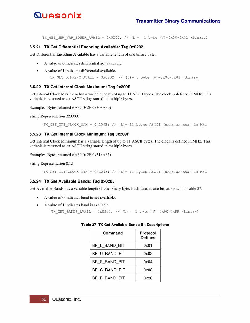
Transmitter Binary Communications
50 Quasonix, Inc.
TX_GET_NEW_VAR_POWER_AVAIL = 0x0206; // (L)= 1 byte (V)=0x00~0x01 (Binary)
6.5.21 TX Get Differential Encoding Available: Tag 0x0202
Get Differential Encoding Available has a variable length of one binary byte.
• A value of 0 indicates differential not available.
• A value of 1 indicates differential available.
TX_GET_DIFFENC_AVAIL = 0x0202; // (L)= 1 byte (V)=0x00~0x01 (Binary)
6.5.22 TX Get Internal Clock Maximum: Tag 0x209E
Get Internal Clock Maximum has a variable length of up to 11 ASCII bytes. The clock is defined in MHz. This
variable is returned as an ASCII string stored in multiple bytes.
Example: Bytes returned (0x32 0x2E 0x30 0x30)
String Representation 22.0000
TX_GET_INT_CLOCK_MAX = 0x209E; // (L)= 11 bytes ASCII (xxxx.xxxxxx) in MHz
6.5.23 TX Get Internal Clock Minimum: Tag 0x209F
Get Internal Clock Minimum has a variable length of up to 11 ASCII bytes. The clock is defined in MHz. This
variable is returned as an ASCII string stored in multiple bytes.
Example: Bytes returned (0x30 0x2E 0x31 0x35)
String Representation 0.15
TX_GET_INT_CLOCK_MIN = 0x209F; // (L)= 11 bytes ASCII (xxxx.xxxxxx) in MHz
6.5.24 TX Get Available Bands: Tag 0x0205
Get Available Bands has a variable length of one binary byte. Each band is one bit, as shown in Table 27.
• A value of 0 indicates band is not available.
• A value of 1 indicates band is available.
TX_GET_BANDS_AVAIL = 0x0205; // (L)= 1 byte (V)=0x00~0xFF (Binary)
Table 27: TX Get Available Bands Bit Descriptions
Command Protocol Defines
BP_L_BAND_BIT 0x01
BP_U_BAND_BIT 0x02
BP_S_BAND_BIT 0x04
BP_C_BAND_BIT 0x08
BP_P_BAND_BIT 0x20
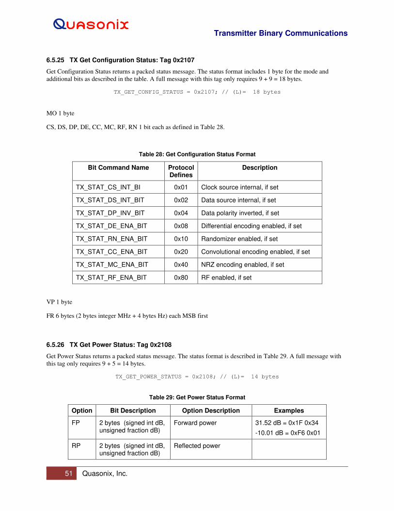
Transmitter Binary Communications
51 Quasonix, Inc.
6.5.25 TX Get Configuration Status: Tag 0x2107
Get Configuration Status returns a packed status message. The status format includes 1 byte for the mode and
additional bits as described in the table. A full message with this tag only requires 9 + 9 = 18 bytes.
TX_GET_CONFIG_STATUS = 0x2107; // (L)= 18 bytes
MO 1 byte
CS, DS, DP, DE, CC, MC, RF, RN 1 bit each as defined in Table 28.
Table 28: Get Configuration Status Format
Bit Command Name Protocol Defines
Description
TX_STAT_CS_INT_BI 0x01 Clock source internal, if set
TX_STAT_DS_INT_BIT 0x02 Data source internal, if set
TX_STAT_DP_INV_BIT 0x04 Data polarity inverted, if set
TX_STAT_DE_ENA_BIT 0x08 Differential encoding enabled, if set
TX_STAT_RN_ENA_BIT 0x10 Randomizer enabled, if set
TX_STAT_CC_ENA_BIT 0x20 Convolutional encoding enabled, if set
TX_STAT_MC_ENA_BIT 0x40 NRZ encoding enabled, if set
TX_STAT_RF_ENA_BIT 0x80 RF enabled, if set
VP 1 byte
FR 6 bytes (2 bytes integer MHz + 4 bytes Hz) each MSB first
6.5.26 TX Get Power Status: Tag 0x2108
Get Power Status returns a packed status message. The status format is described in Table 29. A full message with
this tag only requires 9 + 5 = 14 bytes.
TX_GET_POWER_STATUS = 0x2108; // (L)= 14 bytes
Table 29: Get Power Status Format
Option Bit Description Option Description Examples
FP 2 bytes (signed int dB, unsigned fraction dB)
Forward power 31.52 dB = 0x1F 0x34
-10.01 dB = 0xF6 0x01
RP 2 bytes (signed int dB, unsigned fraction dB)
Reflected power
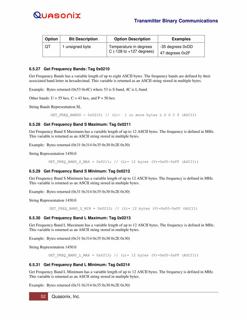
Transmitter Binary Communications
52 Quasonix, Inc.
Option Bit Description Option Description Examples
QT 1 unsigned byte Temperature in degrees C (-128 to +127 degrees)
-35 degrees 0xDD
47 degrees 0x2F
6.5.27 Get Frequency Bands: Tag 0x0210
Get Frequency Bands has a variable length of up to eight ASCII bytes. The frequency bands are defined by their
associated band letter in hexadecimal. This variable is returned as an ASCII string stored in multiple bytes.
Example: Bytes returned (0x53 0x4C) where 53 is S-band, 4C is L-band
Other bands: U = 55 hex, C = 43 hex, and P = 50 hex
String Bands Representation SL
GET_FREQ_BANDS = 0x0210; // (L)= 1 or more bytes L U S C P (ASCII)
6.5.28 Get Frequency Band S Maximum: Tag 0x0211
Get Frequency Band S Maximum has a variable length of up to 12 ASCII bytes. The frequency is defined in MHz.
This variable is returned as an ASCII string stored in multiple bytes.
Example: Bytes returned (0x31 0x314 0x35 0x30 0x2E 0x30)
String Representation 1450.0
GET_FREQ_BAND_S_MAX = 0x0211; // (L)= 12 bytes (V)=0x00~0xFF (ASCII))
6.5.29 Get Frequency Band S Minimum: Tag 0x0212
Get Frequency Band S Minimum has a variable length of up to 12 ASCII bytes. The frequency is defined in MHz.
This variable is returned as an ASCII string stored in multiple bytes.
Example: Bytes returned (0x31 0x314 0x35 0x30 0x2E 0x30)
String Representation 1450.0
GET_FREQ_BAND_S_MIN = 0x0212; // (L)= 12 bytes (V)=0x00~0xFF (ASCII)
6.5.30 Get Frequency Band L Maximum: Tag 0x0213
Get Frequency Band L Maximum has a variable length of up to 12 ASCII bytes. The frequency is defined in MHz.
This variable is returned as an ASCII string stored in multiple bytes.
Example: Bytes returned (0x31 0x314 0x35 0x30 0x2E 0x30)
String Representation 1450.0
GET_FREQ_BAND_L_MAX = 0x0213; // (L)= 12 bytes (V)=0x00~0xFF (ASCII))
6.5.31 Get Frequency Band L Minimum: Tag 0x0214
Get Frequency Band L Minimum has a variable length of up to 12 ASCII bytes. The frequency is defined in MHz.
This variable is returned as an ASCII string stored in multiple bytes.
Example: Bytes returned (0x31 0x314 0x35 0x30 0x2E 0x30)
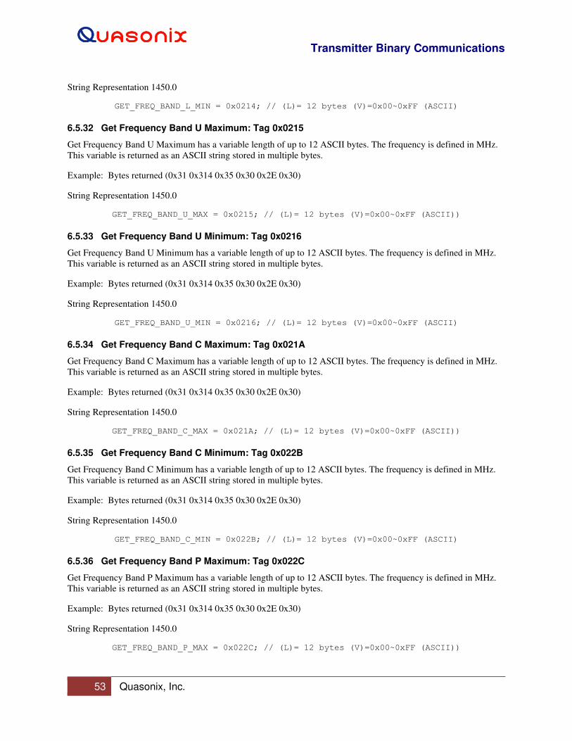
Transmitter Binary Communications
53 Quasonix, Inc.
String Representation 1450.0
GET_FREQ_BAND_L_MIN = 0x0214; // (L)= 12 bytes (V)=0x00~0xFF (ASCII)
6.5.32 Get Frequency Band U Maximum: Tag 0x0215
Get Frequency Band U Maximum has a variable length of up to 12 ASCII bytes. The frequency is defined in MHz.
This variable is returned as an ASCII string stored in multiple bytes.
Example: Bytes returned (0x31 0x314 0x35 0x30 0x2E 0x30)
String Representation 1450.0
GET_FREQ_BAND_U_MAX = 0x0215; // (L)= 12 bytes (V)=0x00~0xFF (ASCII))
6.5.33 Get Frequency Band U Minimum: Tag 0x0216
Get Frequency Band U Minimum has a variable length of up to 12 ASCII bytes. The frequency is defined in MHz.
This variable is returned as an ASCII string stored in multiple bytes.
Example: Bytes returned (0x31 0x314 0x35 0x30 0x2E 0x30)
String Representation 1450.0
GET_FREQ_BAND_U_MIN = 0x0216; // (L)= 12 bytes (V)=0x00~0xFF (ASCII)
6.5.34 Get Frequency Band C Maximum: Tag 0x021A
Get Frequency Band C Maximum has a variable length of up to 12 ASCII bytes. The frequency is defined in MHz.
This variable is returned as an ASCII string stored in multiple bytes.
Example: Bytes returned (0x31 0x314 0x35 0x30 0x2E 0x30)
String Representation 1450.0
GET_FREQ_BAND_C_MAX = 0x021A; // (L)= 12 bytes (V)=0x00~0xFF (ASCII))
6.5.35 Get Frequency Band C Minimum: Tag 0x022B
Get Frequency Band C Minimum has a variable length of up to 12 ASCII bytes. The frequency is defined in MHz.
This variable is returned as an ASCII string stored in multiple bytes.
Example: Bytes returned (0x31 0x314 0x35 0x30 0x2E 0x30)
String Representation 1450.0
GET_FREQ_BAND_C_MIN = 0x022B; // (L)= 12 bytes (V)=0x00~0xFF (ASCII)
6.5.36 Get Frequency Band P Maximum: Tag 0x022C
Get Frequency Band P Maximum has a variable length of up to 12 ASCII bytes. The frequency is defined in MHz.
This variable is returned as an ASCII string stored in multiple bytes.
Example: Bytes returned (0x31 0x314 0x35 0x30 0x2E 0x30)
String Representation 1450.0
GET_FREQ_BAND_P_MAX = 0x022C; // (L)= 12 bytes (V)=0x00~0xFF (ASCII))
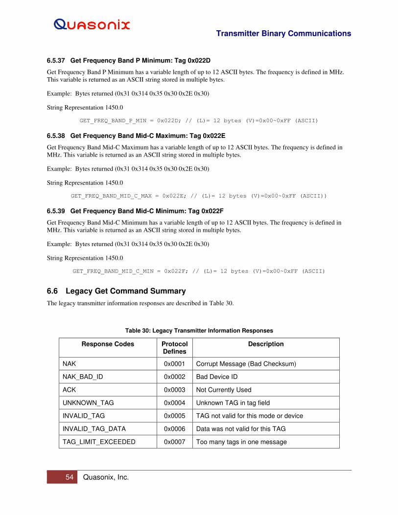
Transmitter Binary Communications
54 Quasonix, Inc.
6.5.37 Get Frequency Band P Minimum: Tag 0x022D
Get Frequency Band P Minimum has a variable length of up to 12 ASCII bytes. The frequency is defined in MHz.
This variable is returned as an ASCII string stored in multiple bytes.
Example: Bytes returned (0x31 0x314 0x35 0x30 0x2E 0x30)
String Representation 1450.0
GET_FREQ_BAND_P_MIN = 0x022D; // (L)= 12 bytes (V)=0x00~0xFF (ASCII)
6.5.38 Get Frequency Band Mid-C Maximum: Tag 0x022E
Get Frequency Band Mid-C Maximum has a variable length of up to 12 ASCII bytes. The frequency is defined in
MHz. This variable is returned as an ASCII string stored in multiple bytes.
Example: Bytes returned (0x31 0x314 0x35 0x30 0x2E 0x30)
String Representation 1450.0
GET_FREQ_BAND_MID_C_MAX = 0x022E; // (L)= 12 bytes (V)=0x00~0xFF (ASCII))
6.5.39 Get Frequency Band Mid-C Minimum: Tag 0x022F
Get Frequency Band Mid-C Minimum has a variable length of up to 12 ASCII bytes. The frequency is defined in
MHz. This variable is returned as an ASCII string stored in multiple bytes.
Example: Bytes returned (0x31 0x314 0x35 0x30 0x2E 0x30)
String Representation 1450.0
GET_FREQ_BAND_MID_C_MIN = 0x022F; // (L)= 12 bytes (V)=0x00~0xFF (ASCII)
6.6 Legacy Get Command Summary
The legacy transmitter information responses are described in Table 30.
Table 30: Legacy Transmitter Information Responses
Response Codes Protocol Defines
Description
NAK 0x0001 Corrupt Message (Bad Checksum)
NAK_BAD_ID 0x0002 Bad Device ID
ACK 0x0003 Not Currently Used
UNKNOWN_TAG 0x0004 Unknown TAG in tag field
INVALID_TAG 0x0005 TAG not valid for this mode or device
INVALID_TAG_DATA 0x0006 Data was not valid for this TAG
TAG_LIMIT_EXCEEDED 0x0007 Too many tags in one message
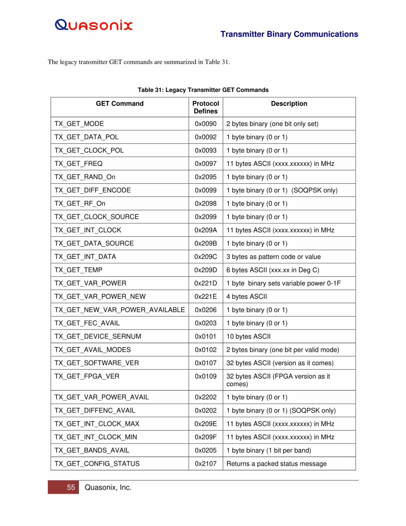
Transmitter Binary Communications
55 Quasonix, Inc.
The legacy transmitter GET commands are summarized in Table 31.
Table 31: Legacy Transmitter GET Commands
GET Command Protocol Defines
Description
TX_GET_MODE 0x0090 2 bytes binary (one bit only set)
TX_GET_DATA_POL 0x0092 1 byte binary (0 or 1)
TX_GET_CLOCK_POL 0x0093 1 byte binary (0 or 1)
TX_GET_FREQ 0x0097 11 bytes ASCII (xxxx.xxxxxx) in MHz
TX_GET_RAND_On 0x2095 1 byte binary (0 or 1)
TX_GET_DIFF_ENCODE 0x0099 1 byte binary (0 or 1) (SOQPSK only)
TX_GET_RF_On 0x2098 1 byte binary (0 or 1)
TX_GET_CLOCK_SOURCE 0x2099 1 byte binary (0 or 1)
TX_GET_INT_CLOCK 0x209A 11 bytes ASCII (xxxx.xxxxxx) in MHz
TX_GET_DATA_SOURCE 0x209B 1 byte binary (0 or 1)
TX_GET_INT_DATA 0x209C 3 bytes as pattern code or value
TX_GET_TEMP 0x209D 6 bytes ASCII (xxx.xx in Deg C)
TX_GET_VAR_POWER 0x221D 1 byte binary sets variable power 0-1F
TX_GET_VAR_POWER_NEW 0x221E 4 bytes ASCII
TX_GET_NEW_VAR_POWER_AVAILABLE 0x0206 1 byte binary (0 or 1)
TX_GET_FEC_AVAIL 0x0203 1 byte binary (0 or 1)
TX_GET_DEVICE_SERNUM 0x0101 10 bytes ASCII
TX_GET_AVAIL_MODES 0x0102 2 bytes binary (one bit per valid mode)
TX_GET_SOFTWARE_VER 0x0107 32 bytes ASCII (version as it comes)
TX_GET_FPGA_VER 0x0109 32 bytes ASCII (FPGA version as it comes)
TX_GET_VAR_POWER_AVAIL 0x2202 1 byte binary (0 or 1)
TX_GET_DIFFENC_AVAIL 0x0202 1 byte binary (0 or 1) (SOQPSK only)
TX_GET_INT_CLOCK_MAX 0x209E 11 bytes ASCII (xxxx.xxxxxx) in MHz
TX_GET_INT_CLOCK_MIN 0x209F 11 bytes ASCII (xxxx.xxxxxx) in MHz
TX_GET_BANDS_AVAIL 0x0205 1 byte binary (1 bit per band)
TX_GET_CONFIG_STATUS 0x2107 Returns a packed status message
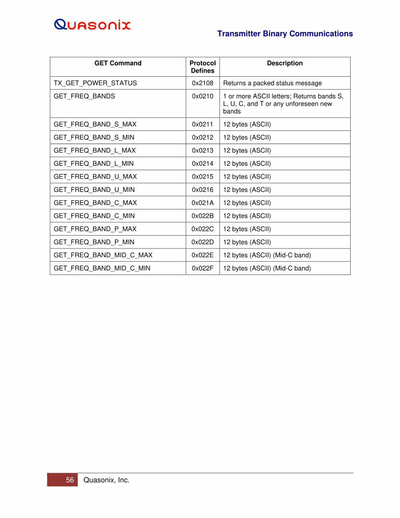
Transmitter Binary Communications
56 Quasonix, Inc.
GET Command Protocol Defines
Description
TX_GET_POWER_STATUS 0x2108 Returns a packed status message
GET_FREQ_BANDS 0x0210 1 or more ASCII letters; Returns bands S, L, U, C, and T or any unforeseen new bands
GET_FREQ_BAND_S_MAX 0x0211 12 bytes (ASCII)
GET_FREQ_BAND_S_MIN 0x0212 12 bytes (ASCII)
GET_FREQ_BAND_L_MAX 0x0213 12 bytes (ASCII)
GET_FREQ_BAND_L_MIN 0x0214 12 bytes (ASCII)
GET_FREQ_BAND_U_MAX 0x0215 12 bytes (ASCII)
GET_FREQ_BAND_U_MIN 0x0216 12 bytes (ASCII)
GET_FREQ_BAND_C_MAX 0x021A 12 bytes (ASCII)
GET_FREQ_BAND_C_MIN 0x022B 12 bytes (ASCII)
GET_FREQ_BAND_P_MAX 0x022C 12 bytes (ASCII)
GET_FREQ_BAND_P_MIN 0x022D 12 bytes (ASCII)
GET_FREQ_BAND_MID_C_MAX 0x022E 12 bytes (ASCII) (Mid-C band)
GET_FREQ_BAND_MID_C_MIN 0x022F 12 bytes (ASCII) (Mid-C band)
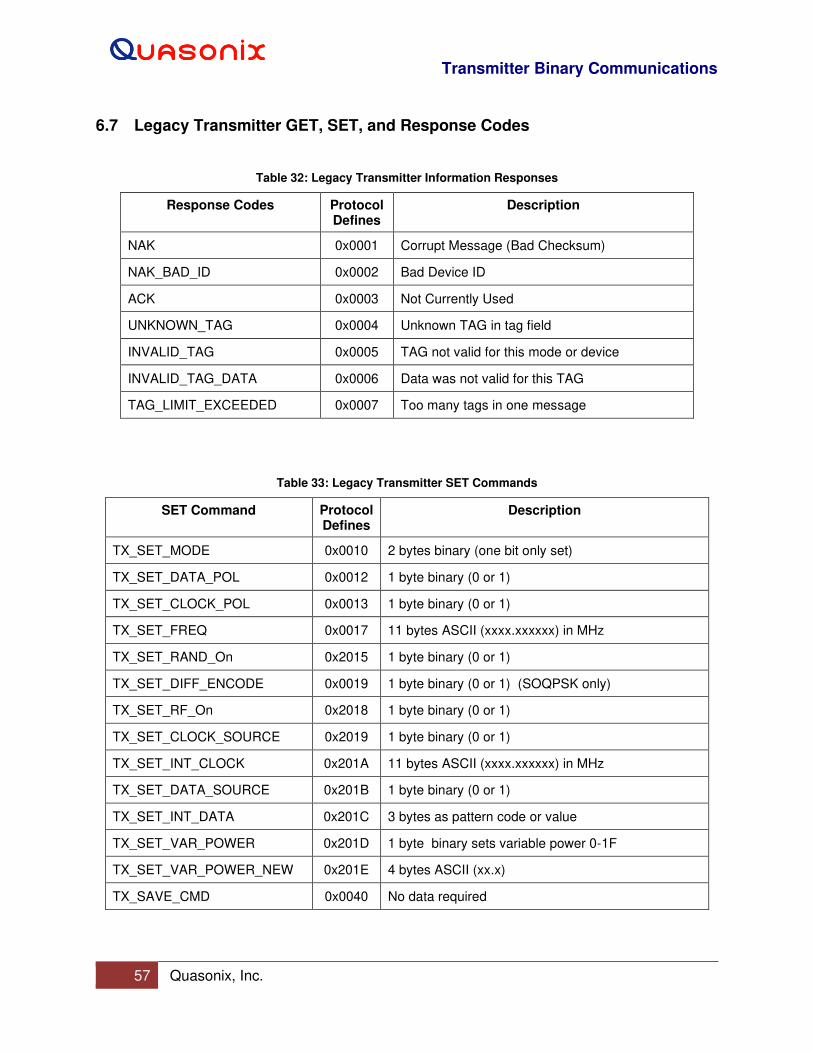
Transmitter Binary Communications
57 Quasonix, Inc.
6.7 Legacy Transmitter GET, SET, and Response Codes
Table 32: Legacy Transmitter Information Responses
Response Codes Protocol Defines
Description
NAK 0x0001 Corrupt Message (Bad Checksum)
NAK_BAD_ID 0x0002 Bad Device ID
ACK 0x0003 Not Currently Used
UNKNOWN_TAG 0x0004 Unknown TAG in tag field
INVALID_TAG 0x0005 TAG not valid for this mode or device
INVALID_TAG_DATA 0x0006 Data was not valid for this TAG
TAG_LIMIT_EXCEEDED 0x0007 Too many tags in one message
Table 33: Legacy Transmitter SET Commands
SET Command Protocol Defines
Description
TX_SET_MODE 0x0010 2 bytes binary (one bit only set)
TX_SET_DATA_POL 0x0012 1 byte binary (0 or 1)
TX_SET_CLOCK_POL 0x0013 1 byte binary (0 or 1)
TX_SET_FREQ 0x0017 11 bytes ASCII (xxxx.xxxxxx) in MHz
TX_SET_RAND_On 0x2015 1 byte binary (0 or 1)
TX_SET_DIFF_ENCODE 0x0019 1 byte binary (0 or 1) (SOQPSK only)
TX_SET_RF_On 0x2018 1 byte binary (0 or 1)
TX_SET_CLOCK_SOURCE 0x2019 1 byte binary (0 or 1)
TX_SET_INT_CLOCK 0x201A 11 bytes ASCII (xxxx.xxxxxx) in MHz
TX_SET_DATA_SOURCE 0x201B 1 byte binary (0 or 1)
TX_SET_INT_DATA 0x201C 3 bytes as pattern code or value
TX_SET_VAR_POWER 0x201D 1 byte binary sets variable power 0-1F
TX_SET_VAR_POWER_NEW 0x201E 4 bytes ASCII (xx.x)
TX_SAVE_CMD 0x0040 No data required
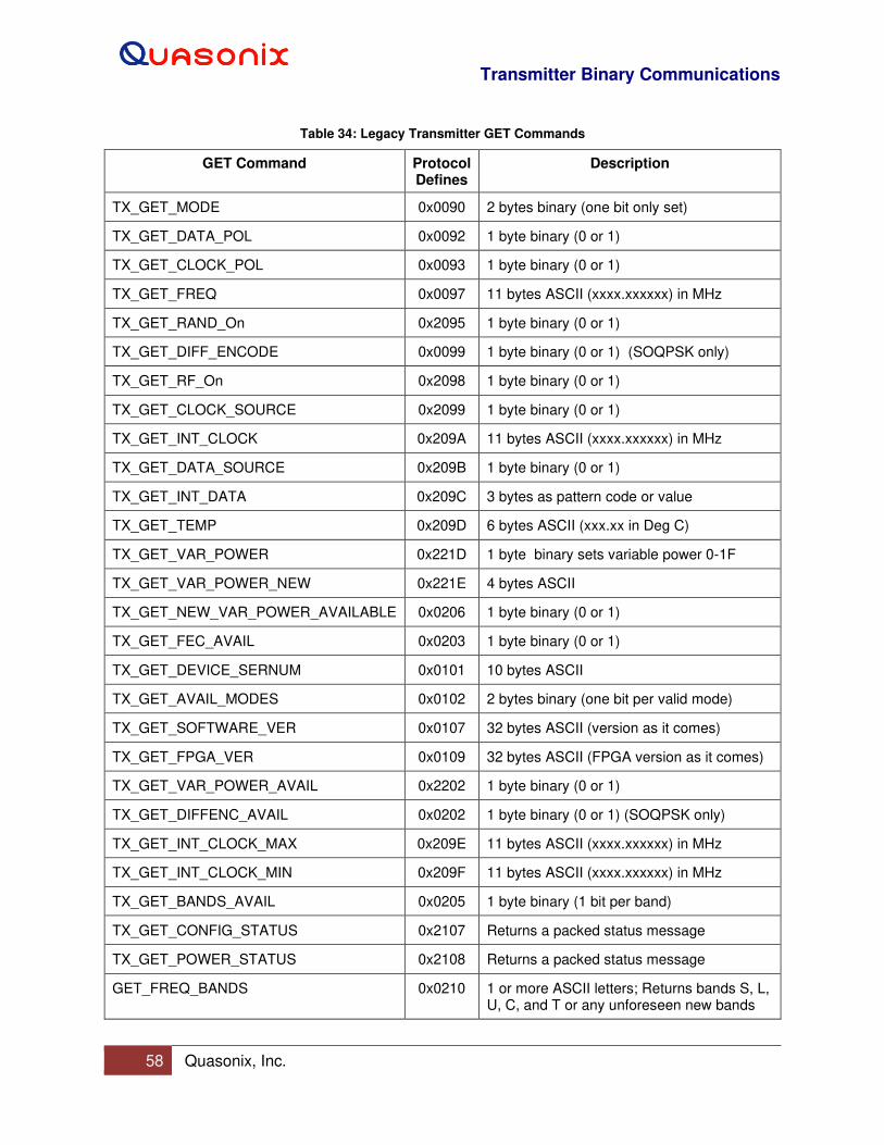
Transmitter Binary Communications
58 Quasonix, Inc.
Table 34: Legacy Transmitter GET Commands
GET Command Protocol Defines
Description
TX_GET_MODE 0x0090 2 bytes binary (one bit only set)
TX_GET_DATA_POL 0x0092 1 byte binary (0 or 1)
TX_GET_CLOCK_POL 0x0093 1 byte binary (0 or 1)
TX_GET_FREQ 0x0097 11 bytes ASCII (xxxx.xxxxxx) in MHz
TX_GET_RAND_On 0x2095 1 byte binary (0 or 1)
TX_GET_DIFF_ENCODE 0x0099 1 byte binary (0 or 1) (SOQPSK only)
TX_GET_RF_On 0x2098 1 byte binary (0 or 1)
TX_GET_CLOCK_SOURCE 0x2099 1 byte binary (0 or 1)
TX_GET_INT_CLOCK 0x209A 11 bytes ASCII (xxxx.xxxxxx) in MHz
TX_GET_DATA_SOURCE 0x209B 1 byte binary (0 or 1)
TX_GET_INT_DATA 0x209C 3 bytes as pattern code or value
TX_GET_TEMP 0x209D 6 bytes ASCII (xxx.xx in Deg C)
TX_GET_VAR_POWER 0x221D 1 byte binary sets variable power 0-1F
TX_GET_VAR_POWER_NEW 0x221E 4 bytes ASCII
TX_GET_NEW_VAR_POWER_AVAILABLE 0x0206 1 byte binary (0 or 1)
TX_GET_FEC_AVAIL 0x0203 1 byte binary (0 or 1)
TX_GET_DEVICE_SERNUM 0x0101 10 bytes ASCII
TX_GET_AVAIL_MODES 0x0102 2 bytes binary (one bit per valid mode)
TX_GET_SOFTWARE_VER 0x0107 32 bytes ASCII (version as it comes)
TX_GET_FPGA_VER 0x0109 32 bytes ASCII (FPGA version as it comes)
TX_GET_VAR_POWER_AVAIL 0x2202 1 byte binary (0 or 1)
TX_GET_DIFFENC_AVAIL 0x0202 1 byte binary (0 or 1) (SOQPSK only)
TX_GET_INT_CLOCK_MAX 0x209E 11 bytes ASCII (xxxx.xxxxxx) in MHz
TX_GET_INT_CLOCK_MIN 0x209F 11 bytes ASCII (xxxx.xxxxxx) in MHz
TX_GET_BANDS_AVAIL 0x0205 1 byte binary (1 bit per band)
TX_GET_CONFIG_STATUS 0x2107 Returns a packed status message
TX_GET_POWER_STATUS 0x2108 Returns a packed status message
GET_FREQ_BANDS 0x0210 1 or more ASCII letters; Returns bands S, L, U, C, and T or any unforeseen new bands
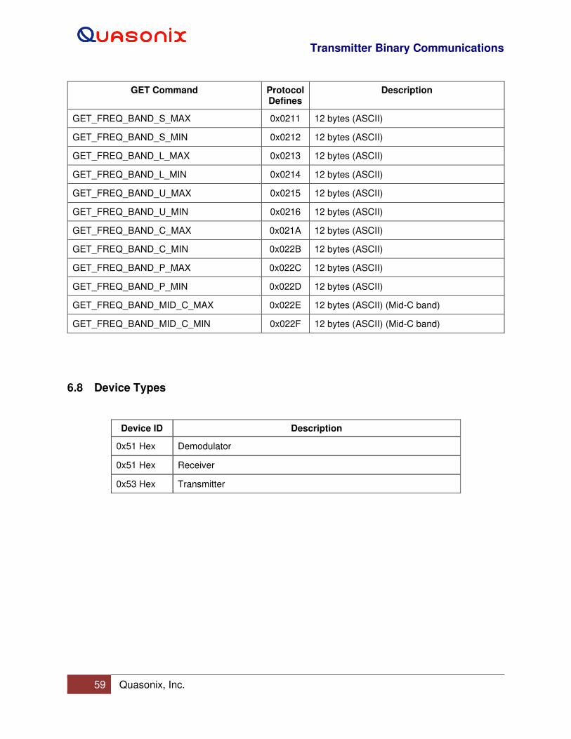
Transmitter Binary Communications
59 Quasonix, Inc.
GET Command Protocol Defines
Description
GET_FREQ_BAND_S_MAX 0x0211 12 bytes (ASCII)
GET_FREQ_BAND_S_MIN 0x0212 12 bytes (ASCII)
GET_FREQ_BAND_L_MAX 0x0213 12 bytes (ASCII)
GET_FREQ_BAND_L_MIN 0x0214 12 bytes (ASCII)
GET_FREQ_BAND_U_MAX 0x0215 12 bytes (ASCII)
GET_FREQ_BAND_U_MIN 0x0216 12 bytes (ASCII)
GET_FREQ_BAND_C_MAX 0x021A 12 bytes (ASCII)
GET_FREQ_BAND_C_MIN 0x022B 12 bytes (ASCII)
GET_FREQ_BAND_P_MAX 0x022C 12 bytes (ASCII)
GET_FREQ_BAND_P_MIN 0x022D 12 bytes (ASCII)
GET_FREQ_BAND_MID_C_MAX 0x022E 12 bytes (ASCII) (Mid-C band)
GET_FREQ_BAND_MID_C_MIN 0x022F 12 bytes (ASCII) (Mid-C band)
6.8 Device Types
Device ID Description
0x51 Hex Demodulator
0x51 Hex Receiver
0x53 Hex Transmitter
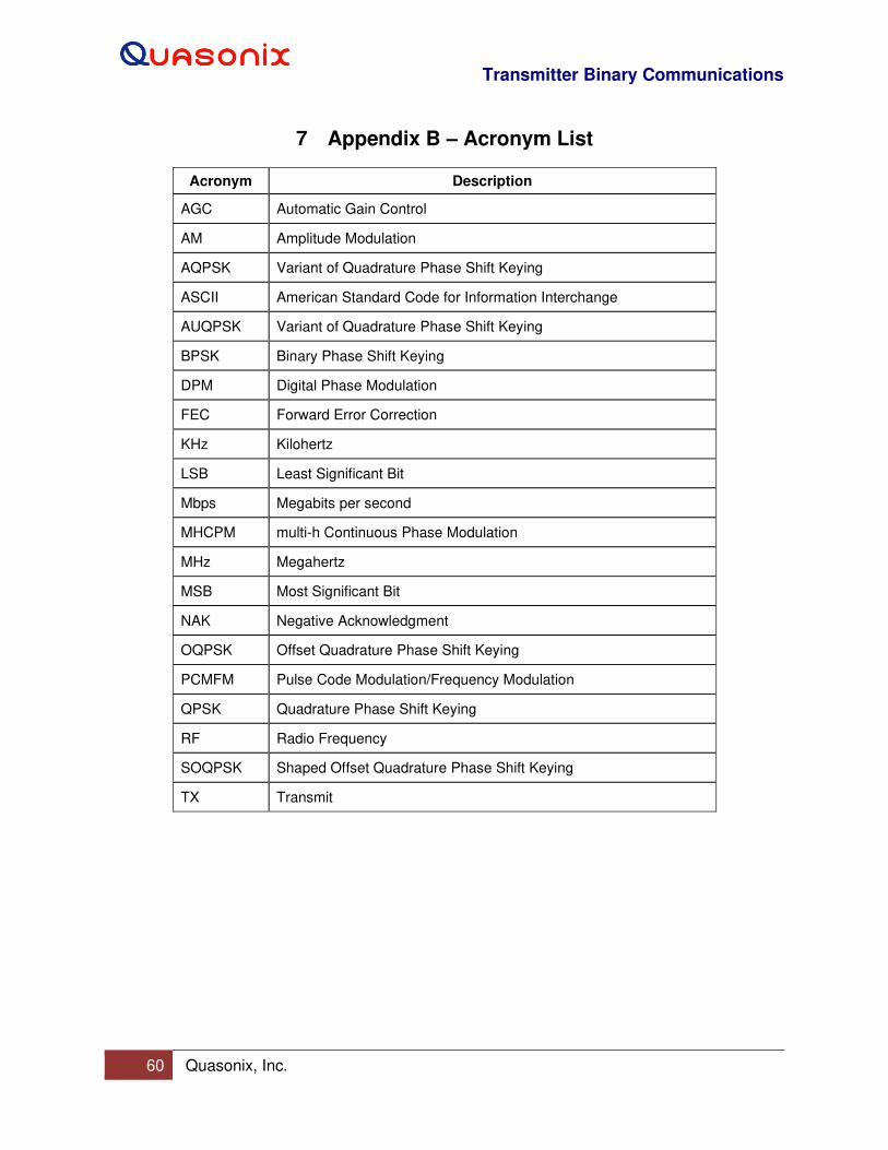
Transmitter Binary Communications
60 Quasonix, Inc.
7 Appendix B – Acronym List
Acronym Description
AGC Automatic Gain Control
AM Amplitude Modulation
AQPSK Variant of Quadrature Phase Shift Keying
ASCII American Standard Code for Information Interchange
AUQPSK Variant of Quadrature Phase Shift Keying
BPSK Binary Phase Shift Keying
DPM Digital Phase Modulation
FEC Forward Error Correction
KHz Kilohertz
LSB Least Significant Bit
Mbps Megabits per second
MHCPM multi-h Continuous Phase Modulation
MHz Megahertz
MSB Most Significant Bit
NAK Negative Acknowledgment
OQPSK Offset Quadrature Phase Shift Keying
PCMFM Pulse Code Modulation/Frequency Modulation
QPSK Quadrature Phase Shift Keying
RF Radio Frequency
SOQPSK Shaped Offset Quadrature Phase Shift Keying
TX Transmit