Embed Size (px)
Citation preview
HAL Id: hal-01022983https://hal.inria.fr/hal-01022983
Submitted on 11 Jul 2014
HAL is a multi-disciplinary open accessarchive for the deposit and dissemination of sci-entific research documents, whether they are pub-lished or not. The documents may come fromteaching and research institutions in France orabroad, or from public or private research centers.
L’archive ouverte pluridisciplinaire HAL, estdestinée au dépôt et à la diffusion de documentsscientifiques de niveau recherche, publiés ou non,émanant des établissements d’enseignement et derecherche français ou étrangers, des laboratoirespublics ou privés.
Quasi-Continuous Mode Conversion of Lamb Waves inCFRP Plates Due to Inhomogeneity on Micro and Meso
ScaleMirko N. Neumann, Bianca Hennings, Rolf Lammering
To cite this version:Mirko N. Neumann, Bianca Hennings, Rolf Lammering. Quasi-Continuous Mode Conversion of LambWaves in CFRP Plates Due to Inhomogeneity on Micro and Meso Scale. EWSHM - 7th EuropeanWorkshop on Structural Health Monitoring, IFFSTTAR, Inria, Université de Nantes, Jul 2014, Nantes,France. �hal-01022983�

QUASI-CONTINUOUS MODE CONVERSION OF LAMB WAVES IN CFRPPLATES DUE TO INHOMOGENEITY ON MICRO AND MESO SCALE
Mirko N. Neumann1, Bianca Hennings1, Rolf Lammering1
1 Helmut-Schmidt-University / University of the Federal Armed Forces HamburgInstitute of Mechanics, Holstenhofweg 85, 22043 Hamburg, Germany
ABSTRACT
The mode conversion of symmetric into antisymmetric Lamb waves in non-damagedCFRP plates caused by their inhomogeneity is discussed. Lamb waves in differentlystacked CFRP plates are observed via scanning laser vibrometry. In addition to the domi-nating wave crests observed propagating through the plates, as predictable from a macro-mechanical point of view, different patterns of parallel lines occur. These are analyzed andclassified into three effects: Mode conversion at micro scale (fibers) and a static bending-stretching coupling effect at meso scale (weave rovings), also causing mode conversionunder additional conditions. To consolidate the findings, tensile tests are performed andobserved with a 3D image correlation method and a volume FE model of a twill fabricwoven layer is used for static as well as dynamic simulations. The numerical results andthe experimental data show a good agreement.
KEYWORDS : Lamb waves, mode conversion, micro scale, meso scale
INTRODUCTION
Lamb waves ( [1], [2–4]) are well-suited for the detection of damages in thin-walled structures ( [4–9]).At any excitation frequency they occur in at least two fundamental modes, the symmetric (Si) andantisymmetric (Ai) modes. Higher wave modes are not discussed here. One effect of Lamb waveinteraction with structural discontinuities is mode conversion: The primary wave group of one modeexcites secondary waves of another mode at a discontinuity. S0 waves converting into A0 waves at anobstacle are depicted in Figure 1, left. The effect is utilized to detect structural damages. In orderdistinguish between damages and natural discontinuities, the systematic mode conversion at fibersand weave rovings in CFRP plates is investigated in this paper. First intense research on the subject isdocumented in [10]. The paper at hand adds fundamental thoughts to the matter, aiming at deepeningthe understanding.
Figure 1 : Laser-vibrometric scans. Left: S0 converting into A0 mode at punctual obstacle (50kHz burst excita-tion in 1mm steel plate). Right: Burst-excited Lamb waves in 1mm aluminium plate at 100kHz.
7th European Workshop on Structural Health MonitoringJuly 8-11, 2014. La Cité, Nantes, France
Copyright © Inria (2014) 2220
The observation of different relevant effects via scanning laser vibrometry is presented. Partsof the results are identified to be caused by a static, position- and direction-dependent coupling ef-fect between in-plane strain and bending via tensile tests. A finite element volume model is usedto simulate both static loading and Lamb wave propagation in a realistically modeled woven CFRPstructure. Simulations of wave propagation in a simplified two-dimensional model are used to show afrequency-influence on the occurrence of mode conversion.
1. LASER-VIBROMETRIC OBSERVATION OF MODE CONVERSION
A common technique for experimental Lamb wave observation is scanning laser vibrometry [11, 12].Here, 1D-vibrometry is used, quantitative errors of the scanning data (see [13,14]) occurring contraryto 3D-vibrometry, are neglected. As a simple example, Lamb waves propagating in circular wavecrests in a homogeneous, isotropic plate, are depicted in Figure 1, right. The waves are excited througha piezoelectric ceramic disc glued to one surface. A two-period sine burst voltage is applied with thedesired frequency. For better frequency selectivity, a von-Hann-window is used.
1.1 CFRP plates consisting of unidirectional layers
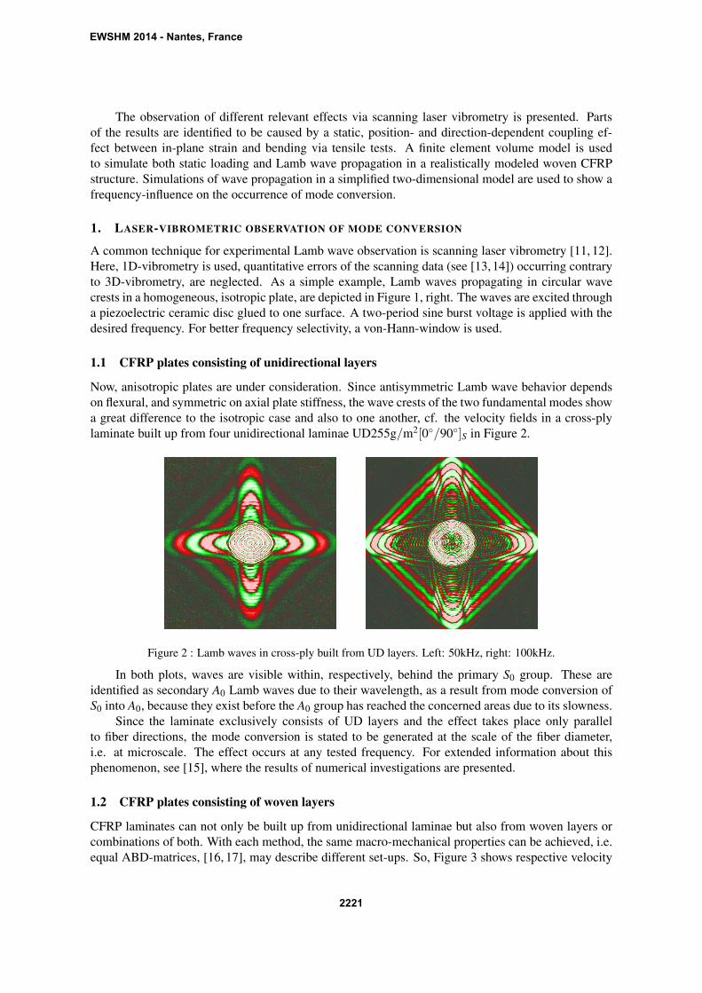
Now, anisotropic plates are under consideration. Since antisymmetric Lamb wave behavior dependson flexural, and symmetric on axial plate stiffness, the wave crests of the two fundamental modes showa great difference to the isotropic case and also to one another, cf. the velocity fields in a cross-plylaminate built up from four unidirectional laminae UD255g/m2[0◦/90◦]S in Figure 2.
Figure 2 : Lamb waves in cross-ply built from UD layers. Left: 50kHz, right: 100kHz.
In both plots, waves are visible within, respectively, behind the primary S0 group. These areidentified as secondary A0 Lamb waves due to their wavelength, as a result from mode conversion ofS0 into A0, because they exist before the A0 group has reached the concerned areas due to its slowness.
Since the laminate exclusively consists of UD layers and the effect takes place only parallelto fiber directions, the mode conversion is stated to be generated at the scale of the fiber diameter,i.e. at microscale. The effect occurs at any tested frequency. For extended information about thisphenomenon, see [15], where the results of numerical investigations are presented.
1.2 CFRP plates consisting of woven layers
CFRP laminates can not only be built up from unidirectional laminae but also from woven layers orcombinations of both. With each method, the same macro-mechanical properties can be achieved, i.e.equal ABD-matrices, [16, 17], may describe different set-ups. So, Figure 3 shows respective velocity
EWSHM 2014 - Nantes, France
2221

fields in a cross-ply laminate built up from six woven twill fabric ’Koper 2/2’ layers 3k[6∗0◦].
Figure 3 : Lamb waves in cross-ply built from twill fabric layers. Left: 50kHz, right: 100kHz.
In addition to the mode conversion parallel to the main axes (right picture only), a 45◦ pattern isvisible within the S0 group. As seen from the right picture, this effect dies away after S0 passes. Thedistance between two lines of the pattern matches the weave structure of the plate surface. It is henceassumed to be a static effect, coupling axial and local bending deformation.
Figure 4 : Left: Geometric shift between layers of a multi-layered cross-ply, right: Lamb waves in single-layertwill fabric plate at 100kHz.
In single layer woven plates, the coupling effect emerges with a greater magnitude due to nocompensation effects due to added stiffness, nor any in-plane shift between different layers (see Figure4, left). Figure 4 (right) depicts Lamb waves in a single layer twill fabric plate. It becomes visible,that no coupling occurs in the encircled areas. Also, straight lines with angles varying from the 45◦
direction emerge. These additional circumstances are discussed later within the paper.
2. EXPERIMENTAL TENSILE TESTS
The assumed coupling effect is investigated via quasi-static tensile testing of single layer twill fabricplates, where the phenomenon appears strongest. A standard tensile testing machine is used to loadspecimens of 25mm width. The displacement observation on the surface is performed with a digital”4D” image correlation system Q-400 from Dantec Dynamics.
The observed surface is speckled with a statistic pattern of high contrast to allow tracking of localdeformation. Two digital cameras record images at every load step, each containing two-dimensional
EWSHM 2014 - Nantes, France
2222
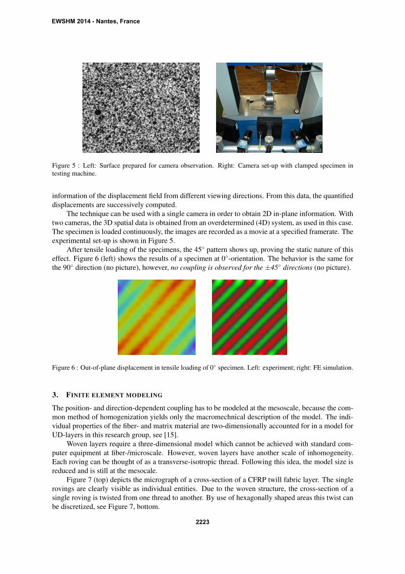
Figure 5 : Left: Surface prepared for camera observation. Right: Camera set-up with clamped specimen intesting machine.
information of the displacement field from different viewing directions. From this data, the quantifieddisplacements are successively computed.
The technique can be used with a single camera in order to obtain 2D in-plane information. Withtwo cameras, the 3D spatial data is obtained from an overdetermined (4D) system, as used in this case.The specimen is loaded continuously, the images are recorded as a movie at a specified framerate. Theexperimental set-up is shown in Figure 5.
After tensile loading of the specimens, the 45◦ pattern shows up, proving the static nature of thiseffect. Figure 6 (left) shows the results of a specimen at 0◦-orientation. The behavior is the same forthe 90◦ direction (no picture), however, no coupling is observed for the ±45◦ directions (no picture).
Figure 6 : Out-of-plane displacement in tensile loading of 0◦ specimen. Left: experiment; right: FE simulation.
3. FINITE ELEMENT MODELING
The position- and direction-dependent coupling has to be modeled at the mesoscale, because the com-mon method of homogenization yields only the macromechnical description of the model. The indi-vidual properties of the fiber- and matrix material are two-dimensionally accounted for in a model forUD-layers in this research group, see [15].
Woven layers require a three-dimensional model which cannot be achieved with standard com-puter equipment at fiber-/microscale. However, woven layers have another scale of inhomogeneity.Each roving can be thought of as a transverse-isotropic thread. Following this idea, the model size isreduced and is still at the mesocale.
Figure 7 (top) depicts the micrograph of a cross-section of a CFRP twill fabric layer. The singlerovings are clearly visible as individual entities. Due to the woven structure, the cross-section of asingle roving is twisted from one thread to another. By use of hexagonally shaped areas this twist canbe discretized, see Figure 7, bottom.
EWSHM 2014 - Nantes, France
2223
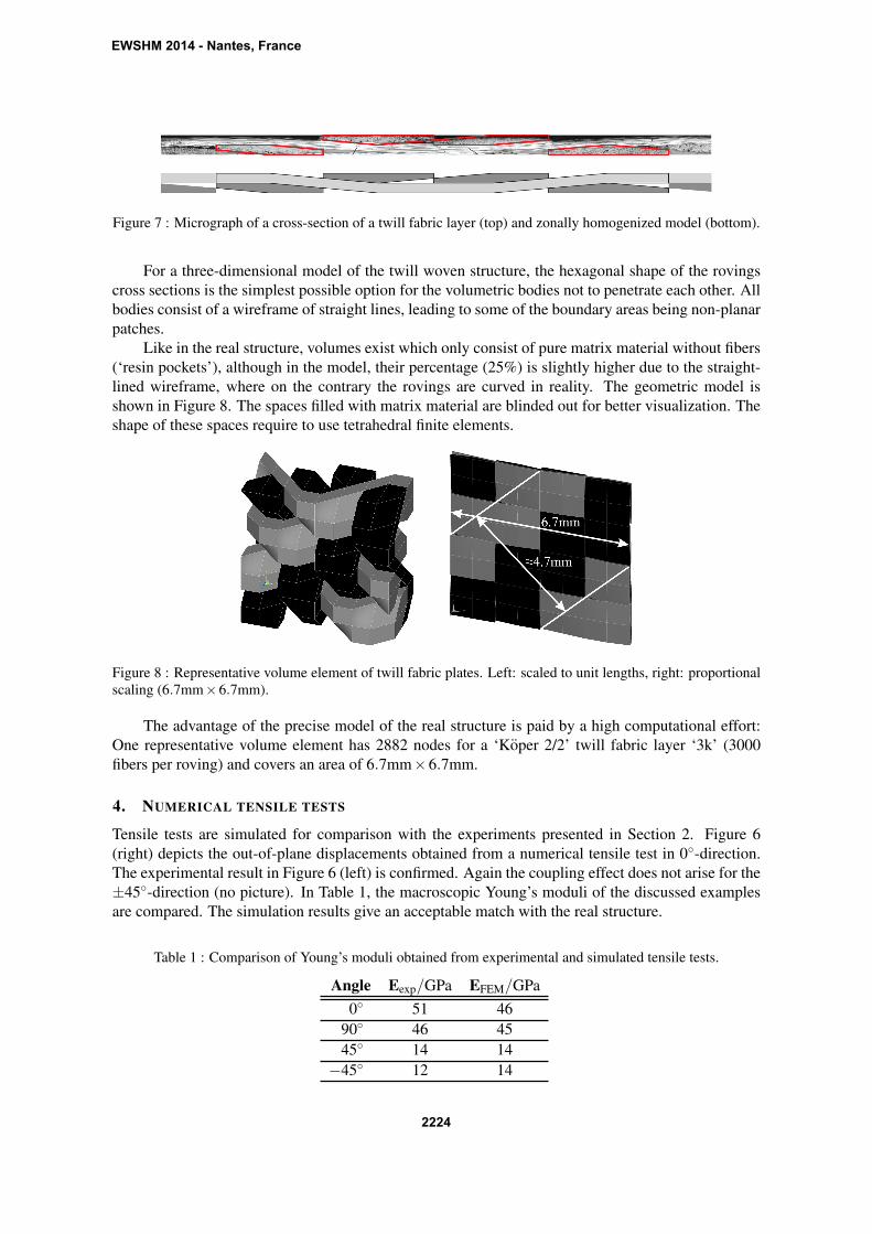
Figure 7 : Micrograph of a cross-section of a twill fabric layer (top) and zonally homogenized model (bottom).
For a three-dimensional model of the twill woven structure, the hexagonal shape of the rovingscross sections is the simplest possible option for the volumetric bodies not to penetrate each other. Allbodies consist of a wireframe of straight lines, leading to some of the boundary areas being non-planarpatches.
Like in the real structure, volumes exist which only consist of pure matrix material without fibers(‘resin pockets’), although in the model, their percentage (25%) is slightly higher due to the straight-lined wireframe, where on the contrary the rovings are curved in reality. The geometric model isshown in Figure 8. The spaces filled with matrix material are blinded out for better visualization. Theshape of these spaces require to use tetrahedral finite elements.
Figure 8 : Representative volume element of twill fabric plates. Left: scaled to unit lengths, right: proportionalscaling (6.7mm×6.7mm).
The advantage of the precise model of the real structure is paid by a high computational effort:One representative volume element has 2882 nodes for a ‘Koper 2/2’ twill fabric layer ‘3k’ (3000fibers per roving) and covers an area of 6.7mm×6.7mm.
4. NUMERICAL TENSILE TESTS
Tensile tests are simulated for comparison with the experiments presented in Section 2. Figure 6(right) depicts the out-of-plane displacements obtained from a numerical tensile test in 0◦-direction.The experimental result in Figure 6 (left) is confirmed. Again the coupling effect does not arise for the±45◦-direction (no picture). In Table 1, the macroscopic Young’s moduli of the discussed examplesare compared. The simulation results give an acceptable match with the real structure.
Table 1 : Comparison of Young’s moduli obtained from experimental and simulated tensile tests.
Angle Eexp/GPa EFEM/GPa
0◦ 51 4690◦ 46 4545◦ 14 14
−45◦ 12 14
EWSHM 2014 - Nantes, France
2224
After building a model containing only the rovings in x-direction, the sign of the local out-of-plane deformation will be constant for any load direction, but the absolute value becomes minimal for90◦ (no picture). Building a model exclusively from y-rovings, the opposite sign occurs for any loaddirection, with a minimum value at 0◦ (no picture).
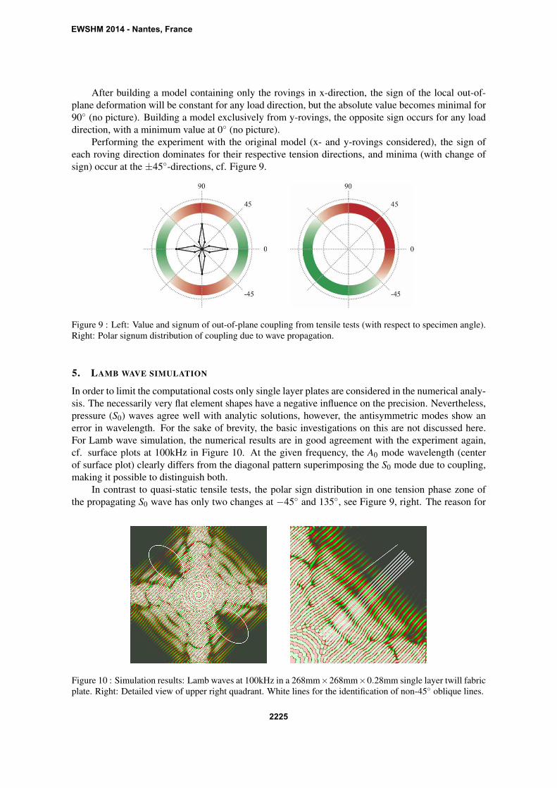
Performing the experiment with the original model (x- and y-rovings considered), the sign ofeach roving direction dominates for their respective tension directions, and minima (with change ofsign) occur at the ±45◦-directions, cf. Figure 9.
Figure 9 : Left: Value and signum of out-of-plane coupling from tensile tests (with respect to specimen angle).Right: Polar signum distribution of coupling due to wave propagation.
5. LAMB WAVE SIMULATION
In order to limit the computational costs only single layer plates are considered in the numerical analy-sis. The necessarily very flat element shapes have a negative influence on the precision. Nevertheless,pressure (S0) waves agree well with analytic solutions, however, the antisymmetric modes show anerror in wavelength. For the sake of brevity, the basic investigations on this are not discussed here.For Lamb wave simulation, the numerical results are in good agreement with the experiment again,cf. surface plots at 100kHz in Figure 10. At the given frequency, the A0 mode wavelength (centerof surface plot) clearly differs from the diagonal pattern superimposing the S0 mode due to coupling,making it possible to distinguish both.
In contrast to quasi-static tensile tests, the polar sign distribution in one tension phase zone ofthe propagating S0 wave has only two changes at −45◦ and 135◦, see Figure 9, right. The reason for
Figure 10 : Simulation results: Lamb waves at 100kHz in a 268mm×268mm×0.28mm single layer twill fabricplate. Right: Detailed view of upper right quadrant. White lines for the identification of non-45◦ oblique lines.
EWSHM 2014 - Nantes, France
2225
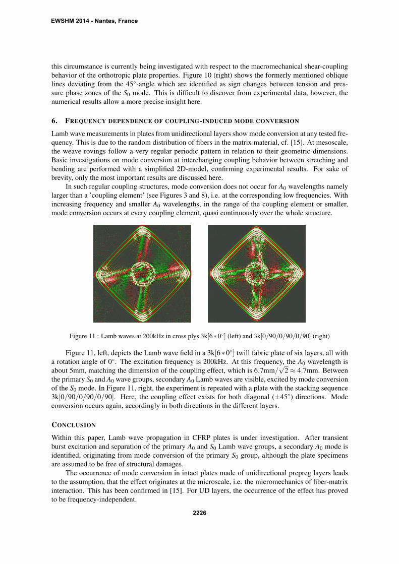
this circumstance is currently being investigated with respect to the macromechanical shear-couplingbehavior of the orthotropic plate properties. Figure 10 (right) shows the formerly mentioned obliquelines deviating from the 45◦-angle which are identified as sign changes between tension and pres-sure phase zones of the S0 mode. This is difficult to discover from experimental data, however, thenumerical results allow a more precise insight here.
6. FREQUENCY DEPENDENCE OF COUPLING-INDUCED MODE CONVERSION
Lamb wave measurements in plates from unidirectional layers show mode conversion at any tested fre-quency. This is due to the random distribution of fibers in the matrix material, cf. [15]. At mesoscale,the weave rovings follow a very regular periodic pattern in relation to their geometric dimensions.Basic investigations on mode conversion at interchanging coupling behavior between stretching andbending are performed with a simplified 2D-model, confirming experimental results. For sake ofbrevity, only the most important results are discussed here.
In such regular coupling structures, mode conversion does not occur for A0 wavelengths namelylarger than a ’coupling element’ (see Figures 3 and 8), i.e. at the corresponding low frequencies. Withincreasing frequency and smaller A0 wavelengths, in the range of the coupling element or smaller,mode conversion occurs at every coupling element, quasi continuously over the whole structure.
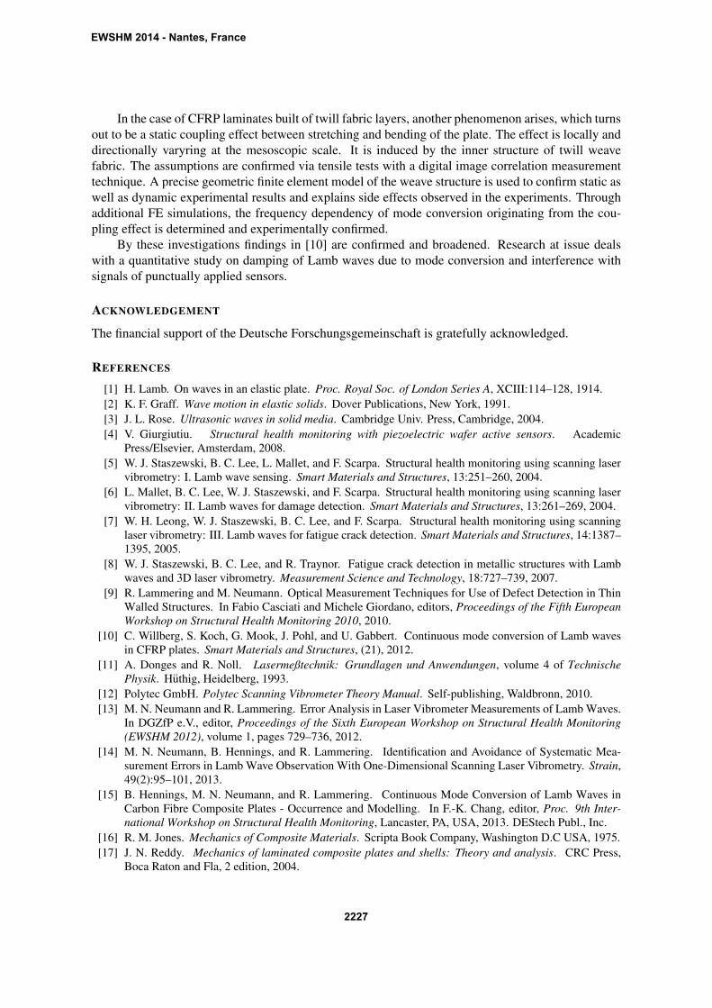
Figure 11 : Lamb waves at 200kHz in cross plys 3k[6∗0◦] (left) and 3k[0/90/0/90/0/90] (right)
Figure 11, left, depicts the Lamb wave field in a 3k[6∗0◦] twill fabric plate of six layers, all witha rotation angle of 0◦. The excitation frequency is 200kHz. At this frequency, the A0 wavelength isabout 5mm, matching the dimension of the coupling effect, which is 6.7mm/
√2 ≈ 4.7mm. Between
the primary S0 and A0 wave groups, secondary A0 Lamb waves are visible, excited by mode conversionof the S0 mode. In Figure 11, right, the experiment is repeated with a plate with the stacking sequence3k[0/90/0/90/0/90]. Here, the coupling effect exists for both diagonal (±45◦) directions. Modeconversion occurs again, accordingly in both directions in the different layers.
CONCLUSION
Within this paper, Lamb wave propagation in CFRP plates is under investigation. After transientburst excitation and separation of the primary A0 and S0 Lamb wave groups, a secondary A0 mode isidentified, originating from mode conversion of the primary S0 group, although the plate specimensare assumed to be free of structural damages.
The occurrence of mode conversion in intact plates made of unidirectional prepreg layers leadsto the assumption, that the effect originates at the microscale, i.e. the micromechanics of fiber-matrixinteraction. This has been confirmed in [15]. For UD layers, the occurrence of the effect has provedto be frequency-independent.
EWSHM 2014 - Nantes, France
2226
In the case of CFRP laminates built of twill fabric layers, another phenomenon arises, which turnsout to be a static coupling effect between stretching and bending of the plate. The effect is locally anddirectionally varyring at the mesoscopic scale. It is induced by the inner structure of twill weavefabric. The assumptions are confirmed via tensile tests with a digital image correlation measurementtechnique. A precise geometric finite element model of the weave structure is used to confirm static aswell as dynamic experimental results and explains side effects observed in the experiments. Throughadditional FE simulations, the frequency dependency of mode conversion originating from the cou-pling effect is determined and experimentally confirmed.
By these investigations findings in [10] are confirmed and broadened. Research at issue dealswith a quantitative study on damping of Lamb waves due to mode conversion and interference withsignals of punctually applied sensors.
ACKNOWLEDGEMENT
The financial support of the Deutsche Forschungsgemeinschaft is gratefully acknowledged.
REFERENCES
[1] H. Lamb. On waves in an elastic plate. Proc. Royal Soc. of London Series A, XCIII:114–128, 1914.[2] K. F. Graff. Wave motion in elastic solids. Dover Publications, New York, 1991.[3] J. L. Rose. Ultrasonic waves in solid media. Cambridge Univ. Press, Cambridge, 2004.[4] V. Giurgiutiu. Structural health monitoring with piezoelectric wafer active sensors. Academic
Press/Elsevier, Amsterdam, 2008.[5] W. J. Staszewski, B. C. Lee, L. Mallet, and F. Scarpa. Structural health monitoring using scanning laser
vibrometry: I. Lamb wave sensing. Smart Materials and Structures, 13:251–260, 2004.[6] L. Mallet, B. C. Lee, W. J. Staszewski, and F. Scarpa. Structural health monitoring using scanning laser
vibrometry: II. Lamb waves for damage detection. Smart Materials and Structures, 13:261–269, 2004.[7] W. H. Leong, W. J. Staszewski, B. C. Lee, and F. Scarpa. Structural health monitoring using scanning
laser vibrometry: III. Lamb waves for fatigue crack detection. Smart Materials and Structures, 14:1387–1395, 2005.
[8] W. J. Staszewski, B. C. Lee, and R. Traynor. Fatigue crack detection in metallic structures with Lambwaves and 3D laser vibrometry. Measurement Science and Technology, 18:727–739, 2007.
[9] R. Lammering and M. Neumann. Optical Measurement Techniques for Use of Defect Detection in ThinWalled Structures. In Fabio Casciati and Michele Giordano, editors, Proceedings of the Fifth EuropeanWorkshop on Structural Health Monitoring 2010, 2010.
[10] C. Willberg, S. Koch, G. Mook, J. Pohl, and U. Gabbert. Continuous mode conversion of Lamb wavesin CFRP plates. Smart Materials and Structures, (21), 2012.
[11] A. Donges and R. Noll. Lasermeßtechnik: Grundlagen und Anwendungen, volume 4 of TechnischePhysik. Huthig, Heidelberg, 1993.
[12] Polytec GmbH. Polytec Scanning Vibrometer Theory Manual. Self-publishing, Waldbronn, 2010.[13] M. N. Neumann and R. Lammering. Error Analysis in Laser Vibrometer Measurements of Lamb Waves.
In DGZfP e.V., editor, Proceedings of the Sixth European Workshop on Structural Health Monitoring(EWSHM 2012), volume 1, pages 729–736, 2012.
[14] M. N. Neumann, B. Hennings, and R. Lammering. Identification and Avoidance of Systematic Mea-surement Errors in Lamb Wave Observation With One-Dimensional Scanning Laser Vibrometry. Strain,49(2):95–101, 2013.
[15] B. Hennings, M. N. Neumann, and R. Lammering. Continuous Mode Conversion of Lamb Waves inCarbon Fibre Composite Plates - Occurrence and Modelling. In F.-K. Chang, editor, Proc. 9th Inter-national Workshop on Structural Health Monitoring, Lancaster, PA, USA, 2013. DEStech Publ., Inc.
[16] R. M. Jones. Mechanics of Composite Materials. Scripta Book Company, Washington D.C USA, 1975.[17] J. N. Reddy. Mechanics of laminated composite plates and shells: Theory and analysis. CRC Press,
Boca Raton and Fla, 2 edition, 2004.
EWSHM 2014 - Nantes, France
2227


![Attenuation of Lamb Waves in CFRP Plates · wave attenuation characteristics and AE has encountered stiff barriers against its uses in the air-craft industry [1,2]. Problems are mounted](https://img.pdfslide.us/doc/110x75/5e705467b7bed33a0c09ca37/attenuation-of-lamb-waves-in-cfrp-plates-wave-attenuation-characteristics-and-ae.jpg)


![Lamb Wave Mode Conversion in CFRP Plates) mode. At higher frequencies higher order modes occur [5, 7] and under specific conditions the modes may convert into each other. Most often](https://img.pdfslide.us/doc/110x75/5fe8556370a3734a00091c47/lamb-wave-mode-conversion-in-cfrp-plates-mode-at-higher-frequencies-higher-order.jpg)