Embed Size (px)
Citation preview

QUENCY CCNTROLad
QUARTZ CRYSTA
ENGINEERING BULLETIN E-6
PRICE 10 CENTS

T"E 1.0 2f3LI LEY
fREOUENCY-CONTROLscfuNt. Nomeert
Catalogs describing the
complete line of Bliley
Crystals, Holders and Ovens
for amateur and general
communicationfrequencies
can obtained from your
disttibutor.
This booklet,prepared by the engineering staff
of she Bliley Electric Company,covers the general
theory and application of quartz piezoelectric
crystals. Its purpose is to provide engineers,
experimentersand amateurs with information not
otherwise easily obtainable in any one publi-
cation. Naturally, some of the material presented
does not appear elsewhere.
No attempt has been made torecommend or to
present specific designscrsmplete with construc-
rovide generalized
details. The intent is to p
informationwhich will enable the reader
broad understandingof the subject.
be attaci'<ed
individual designs or problems canassurance of
with better understandingand greater
successful solution.
Extracts or reproductionsof all, or any part, of
this booklet are restricted to individuals or organi-
been ex'
zations to whom direct permission has
tended by the Bliley Electric Company.
April, 19381st printing ..........2nd printing ....... August, 1938
3rd printing .........July, 1939
Revised edition . . . October, 1940
6th Printing " April, 1942

sciAle of eon/en/5
Page
Theoretical Considerations2
Crystals at Anti -Resonance
4
Crystals at Resonance
5
Effects of Temperature
7
Modes of Vibration7
Crystal Holders
8
Crystal Power
11
Crystal Activity
13
Crystal Cleaning
14
Crystal Controlled Oscillators14
18 Mc. to 30 Mc. Crystal Oscillators21
Low Frequency Oscillators23
Oscillator Keying25
Frequency Standards27
Primary Standards of Frequency27
SecondaryStandards of Frequency
29
The Multivibrator31
General Operating Notes33
Engineering BulletinE-6
Printed in U. S. A.
Copyright 1940BLILEY ELECTRIC CO.
Erie, Penna.
\t,
FREQUENCY CONTROL with QUARTZ CRYSTALS
THEORETICAL CONSIDERATIONS
Certain crystalline substances, such as quartz,Rochelle Salts and tourmaline, exhibit a most in-teresting property. In brief, if any one of thesesubstances is distorted mechanically an electriccharge will be developed; and, conversely, me-chanical distortion will result if the substance is
placed in an electric field. This property, thePiezoelectric Effect, makes possible precisionfrequency -control of radio transmitting equipment.
There are a surprisingly large number of cry-stalline substances which do exhibit piezoelectricproperties but, out of the entire group, quartzis the only material which is truly satisfactory forfrequency control purposes. Rochelle Salts ex-hibits the most intensepiezoelectric proper-ties but is not a suitablematerial for it is too un-stable both physicallyand electrically. Tour-maline, a gem material,has been employed butdue to its relatively highcost and the superiorqualities of quartz, it isno longer in generaluse.
Quartz is silica (sili-con dioxide) and is
found throughout theworld in many differentforms. It appears mostcommonly in the sandsand sandstones of the earth and occurs in variousrocks of igneous origin such as granite. Some
varieties of quartz, including amethyst and rosequartz, are cut into gems and ornaments. Amongstits many commercial applications, quartz is used inthe manufacture of piezoelectric devices, lenses,balance weights, chemical ware and abrasives.Because of its extremely low internal friction andsmall thermal expansion coefficient, quartz, fusedand drawn into very fine threads, is highly valuedfor suspensions in scientific apparatus.
Quartz is an exceptionally hard material havinga rating of 7 in Moh's Scale of Hardness wherethe diamond is rated at 10. It is very stable bothphysically and chemically; it is not affected bycommon acids and can be fused only with con-siderable difficulty. For general scientific and
Figure 1-Group of Natural Quartz Crystals
piezoelectric applications, comparatively large
natural crystals of high purity are required. Al-though natural crystals can be found in many dif-ferent parts of the world, including the U. S. A.,Brazil, at present, has the only suitable source ofsupply.
To take advantage of the piezoelectric effect ofquartz, it is necessary to cut small "plates" from theraw natural crystals. These plates must be cut incertain definite directions with respect to the axesof the raw crystals, they must be free From mechanicaland electrical flaws, and each must be carefullyground such that its major faces are essentiallyplane and parallel. If one of these plates is placedin an oscillating electric field, it will vibratemechanically and produce a counter -Voltage at the
frequency of the appliedfield. The magnitude ofthis action will be quitesmall, but, should thefrequency of the appliedfield be adjusted to cor-respond with a naturalvibrating period of theplate, the vibrations willbecome vigorous and
have an appreciable
amplitude. In fact,
should the strength ofthe applied field be suf-ficiently great, the vi-
brations can easily be-come so strong that the
plate will be physicallyruptured.
This same plate, if distorted by physical force, willdevelop an electric charge. If the plate is X -cut(that is, the planes of its faces perpendicular to thedirection of one of the side faces of the naturalcrystal and parallel to the axis of the crystal alongits length and through the peak) and the force isnormal to the major faces, the charge developedwill be very nearly 10-11 coulombs per pound(6.36 x 10⁻⁸ e.s.u. /dyne). This charge will beessentially independent of crystal face area or
thickness and of temperature for any value up toabout 550°C., at 573°C., piezoelectric action willcease. For pressure measurement purposes, theamount of charge, or the voltage resulting from the
charge, can be determined. The voltage is, of
course, proportional to the charge divided by the
circuit capacity (C) = CE).
2

EL
IC C
OM
PA
NY
Manufacturers of Q
UA
RT
Z
UN
ION
ST
AT
ION
BU
ILDIN
G, E
RIE
,P
EN
NS
YLV
AN
IA
June 22, 1939.
to.
Mr. Bertram Aaron,
6811 Huntington Avenue,
Newport News, Virginia.
Dear Sir:
This will acknowledge and thankyou for your remittance of
$5.75 and your letter of June 15, specifying one HF2 10 -
meter crystal unit at approximately 29.25mc.
Your order
has been released for production and shipment of the crystal
went forward to you on June 20 under our packing slip No.
aging of the tube or circuit components, or othercauses, necessitates a change in frequency to againbring the net circuit reactance to zero. Becausequartz crystals have a very steep resonance curve,a large change in reactance can be brought aboutwith only a small shift in circuit frequency.
CRYSTALS AT RESONANCE
In oscillator circuits, employed for the majorityof radio transmitter installations, the crystal operatesin the same manner as a parallel, or anti -resonant,electrical circuit. For this reason, quartz crystalsemployed for frequency control of vacuum tubeoscillators usually are calibrated at their anti -
resonant frequencies.
The effective value of the capacity, C1, changeswhen a crystal is placed in a vacuum tube oscillatorcircuit. In the theoretical analysis, Ci representsthe capacity between the. crystal electrodes withthe crystal acting as the dielectric. When, how-ever, the crystal is connected in an actual circuit,the value of Ci will vary with different crystalholders and will, in addition, be affected by thedynamic input impedance of the oscillator tube andthe capacity added by connecting wires betweenthe crystal and the tube. The impedance in theplate circuit of the tube will, naturally, also in-fluence the dynamic impedance of the grid circuitto an extent dependent on individual operatingconditions.
It is evident that the total capacity added to Cl bythe oscillator will vary between different circuitsand layouts, thereby causing the crystal frequencyto assume different values in each particular oscil-lator setup. Because of the possible variationsin frequency, Bliley Crystals normally are guaranteedto operate within a certain variation from the cali-brated frequency (generally .02%-.03%, includingcustomary manufacturing frequency tolerance) whenoperated in the purchaser's equipment despite thefact that each crystal is accurately calibrated in themanufacturing laboratory. The crystals are, for thesame reason, supplied complete with holders only.For details concerning crystal specifications to meetdefinite frequency accuracy requirements, referenceshould be made to Bliley Catalog G-12. Thispublication contains pertinent information relativeto the choice of crystals and mountings for allservices other than amateur.
When a quartz crystal is required for a specificservice or application where frequency accuracy ismost important, the possible change in frequencybetween the manufacturer's calibrating oscillatorand the final equipment must be considered. This
is especially important where the allowable fre-quency tolerance is very small.
By taking advantage of the fact that the parallelcapacity will influence the frequency of a crystal,it is possible to include a variable frequencyfeature. This is invaluable to radio broadcastservices in the standard broadcast band where thecarrier must be held within 20 cycles of the assignedvalue. It is an equally valuable feature in manyother services where the frequency must be heldwithin close limits and in amateur service where a
simple method of shifting the station frequency oftenpermits contacts under ordinarily impossible con-ditions of interference.
There are two methods of effecting the changein the oscillating frequency of a crystal operating at,or near, anti -resonance. The obvious arrangementis to connect a variable air -condenser in parallelwith the crystal to bring about a variation in C1,(figure 2). As the capacity of the condenser is in-creased, the frequency will be lowered until thecapacity becomes sufficiently large to effectivelyshort out the crystal. In any event, the addedcapacity will 'load up' the crystal thereby de-creasing its oscillating ability. For small ranges offrequency adjustment the effect of the condenserwill not be harmful, however, and the decrease inthe oscillating properties of the crystal is readilyoffset by the variable frequency feature. This
method of shifting the frequency is generally appliedwith crystals higher than 2000kc. but can be usedat lower frequencies if desirable. At the veryhigh frequencies it is not particularly satisfactorybecause the amount of capacity sufficient to stoposcillation is quite small. This, of course, greatlylimits the amount by which the frequency can bevaried.
A variable air -gap crystal holder offers the mostconvenient method for shifting frequency. In a
typical holder of this type, one of the crystal elec-trodes is mounted on a micrometer screw such thatthe electrode may be raised or lowered over thecrystal. This brings about a simultaneous change inthe values of Ci and C2 (figure 2). When theair -gap between the movable electrode and thecrystal is increased, the frequency will be raisedwith an accompanying decrease in oscillatingproperties. For small ranges of frequency adjust-ment, the detrimental effect of the air -gap is notserious and the only essential consideration is thatthe crystal be used in a circuit where the drivingvoltage will not reach high values. Unless this pre-caution is taken, an arc will be developed acrossthe air -gap causing erratic oscillation and, some-times, damaging the crystal because of the con-centrated heat of the arc.
L
4
EL
IC C
OM
PA
NY
Manufacturers of Q
UA
RT
Z
UN
ION
ST
AT
ION
BU
ILDIN
G,
ER
IE, P
EN
NS
YLV
AN
IA
June 22, 1939.
Mr. Bertram Aaron,
6811 Huntington
Avenue,
Newport News, Virginia.
Dear Sir:
This will acknowledge and
thankyou for your remittance of
$5.75 andyour letter of June 15, specifying one HF2 10-
meter crystal unit at
approximately 29.25mc.
Your order
has been released forproduction and shipment of the
crystal
went forward to
you on June 20 under our, packing slip No.
110-vp
impedance drops to a low value thereby upsettingthe balance and permitting a signal voltage toappear on the grid of the amplifier tube.
Despite the apparent simplicity of the filter circuit,an exact analysis of its operation is most difficult;practically all filters of this type are designed em-pirically on the basis of experimental data. For a
basic understanding of the principles involved,however, it is convenient first to assume that thebridge is perfectly balanced. The lower portionof the bridge, including the balancing condenser
can then be ignored for practical purposes. It
now can be seen that the induced voltage in the
upper half of the secondary of transformer Ti is inseries with the impedance of the transformer sec-ondary, the crystal, and the output transformer T2 asshown in figure 5.
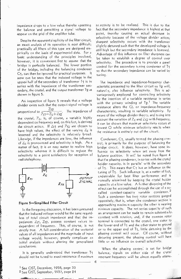
An inspection of figure 5 reveals that a voltagedivider exists such that the output signal voltage is
Zt2proportional to
Zt1-1-Zc-I-Zt2.The impedance of
the crystal, Zc, is, of course, a variable highlydependent on frequency and, on this fact, is derivedthe circuit action. If Zti and Zt2 are chosen tohave high values, the effect of the varying Zc islessened and the selectivity is relatively broad.Likewise, if the impedances are low, the influenceof Zc is pronounced and selectivity is high. As amatter of fact, it is an easy matter to realize highselectivity whereas it is difficult to reduce theselectivity to a point satisfactory for reception ofradiotelephony.
Zr. IOUTPUTS/aNAL.
Figure 5-Simplified Filter Circuit
In the foregoing discussion, it has been presumedthat the induced voltage would be the same regard-less of total circuit impedance and that the im-pedances Zti, Zt2, possess constant values in-
dependent of frequency. This, of course, is notstrictly true. A full consideration of the vectorialvalues of all impedances and the magnitude of inputvoltage would, however, greatly complicate aninitial analysis without altering the generalized
conclusions.
It is generally understood that transformer Tishould not be tuned to exact resonance if maximum
selectivity is to be realized. This is due to thefact that the secondary impedance is highest at thatpoint, thereby causing an actual decrease inselectivity because of the voltage divider action;sharpest selectivity occurs with the transformerslightly detuned such that the developed voltage isstill high but the secondary impedance is lowered.Advantage of this influence on filter sharpness canbe taken to establish a degree of control overselectivity. The procedure is to provide a panelcontrol for the secondary tuning condenser of T1so that the secondary impedance can be varied bytuning.
The impedance and impedance -frequency char-acteristic presented to the filter circuit by T2 will,naturally, also influence selectivity. This is ad-vantageously employed for controlling selectivityby the insertion of a variable resistance in serieswith the primary winding of T2.1 The variableresistance alters the 0, or impedance -frequencycharacteristic, resulting in variable selectivity. By
means of the voltage divider theory, and taking intoaccount the variation of Zc and Zt2 with frequency,it can be shown that maximum selectivity cccurs atlowest 0 while minimum selectivity results whenthe resistance is entirely out of the circuit.
Condenser, C1, usually termed the phasing con-trol, is primarily for the purpose of balancing thebridge circuit. It does, however, have some in-fluence on selectivity when set away from thebalance position. It will be noted from figure 4that the phasing condenser, in series with the crystalholder capacity, is in parallel with the secondaryof Ti. This means that Ci has an influence on thetuning of T1. Such influence is, as a matter of fact,
undesirable for best filter performance and is
normally minimized by keeping the crystal holdercapacity at a low value. A further divorcing of the
effect can be accomplished through the use of a so-called constant -capacity variable condenser. 2
Such a condenser has two rotor sections gangedoppositely; that is, when one condenser section isapproaching maximum capacity the other is nearingminimum capacity. The net series capacity of suchan arrangement can be made to remain substantially
constant with rotation, and, if the common rotorterminal is connected to the crystal, one stator tothe lower end of Ti and the other stator to groundor to the upper end of T1, little detuning by the
phasing control will occur. Of course, withoutdetuning present, the phasing control will havelittle or no influence on overall selectivity.
When the phasing control is set for bridgebalance, signals on either side of the crystal
resonant frequency will be almost equally attenu-
1 See OST, December, 1938, page 332 See OST, September, 1937, page 24
6
ated. If, however, the control is set somewhataway from balance position, the attenuation at someside frequency will be considerably increased. Thisis a useful feature in communications because itenables the operator to emphasize attentuation ona particular interfering signal whose frequency isclose to the one desired.
The action of the phasing control in rejectingsignals is simply a matter of circuit balance. For
any particular setting of the phasing control, otherthan for perfect balancing of the crystal holdercapacity, there will be one frequency which willbe passed in nearly equal magnitude, but in op-posite phase, through the crystal arm and throughthe phasing control arm of the filter circuit. Be-
cause the voltage in each arm is out of phase atthe common terminal, cancellation occurs. Whetherthe rejection point exists above or below theresonant frequency of the crystal depends, ofcourse, on the actual capacity of the phasing con-denser, with respect to the capacity required forperfect bridge balance.
EFFECTS OF TEMPERATURE
The frequency of a crystal is influenced to anappreciable extent by the temperature at which itis operated. The magnitude of this effect is deter-mined by the manner in which the crystal is cutfrom the natural quartz, the shape and size of thecrystal, the precision of grinding, and the character-istics of the quartz itself. It is expressed as thenumber of cycles change per million cycles of crystalfrequency per degree Centigrade variation in tem-perature and is termed the temperature coefficient offrequency or the frequency -temperature coefficient.A positive (+)temperature coefficient indicates thatthe crystal frequency increases with increasing tem-perature, whereas a negative (-) coefficient in-dicates that the frequency will decrease with in-creasing temperature.
The frequency -temperature coefficient of a
quartz crystal varies, with individual cuts, fromminus 25 to plus 100 cycles per megacycle perdegree Centigrade. With X-, C-, or E -cut crystals,the frequency at any temperature can be deter-mined from a knowledge of the frequency -
temperature coefficient and the crystal frequencyat any other temperature. Such calculations arenot accurately possible with low frequency -temperature coefficient crystals (often referred to as I
zero" temperature coefficient crystals) becausethe curve of frequency versus temperature is notgenerally a straight line; in fact, the coefficient maybe positive over one part of the total temperaturerange and negative over other portions. It is
commercial practice, with these crystals, to statethe average frequency -temperature coefficient overa given range of temperature (generally 20°C. to55°C.).
The operating temperature of a crystal is de-pendent on the ambient temperature, the amountof heat developed by the crystal in oscillating andthe rate of heat dissipation by the crystal holder.It can be seen, therefore, that for highest frequencystability, unless automatic temperature control is
employed, a crystal holder having high heat dis-sipating abilities should be used. In addition, theintensity of vibration should be maintained at thelowest possible value to keep the developed heatat a minimum. Where a very high degree of fre-quency stability is required, the crystal temperatureshould be controlled by a constant -temperatureoven.
MODES OF VIBRATION
Any quartz crystal has two, and sometimes three,widely separated possible frequencies of oscilla-tion. This is due to the fact that a vibrating body ofthis general type can be caused to vibrate in at leasttwo different manners (modes). Furthermore, animproperly finished plate -type crystal may have oneor two additional frequencies close to the thick-ness frequency. This is possible when the facesare insufficiently plane and parallel such that thecrystal may oscillate at slightly different frequenciesover small portions of the surface.
By properly choosing the mode of vibration, it ispossible ,to manufacture quartz crystals of practicaldimensions over a very wide frequency range. In
the present state of development, they are producedin the full range from 16kc. to 30,000kc.
X -cut plates, also known as the Curie Cut, werethe first type of quartz oscillating crystals to bedeveloped. These crystals oscillate through thethickness at a frequency largely determined by thatdimension. They have a negative frequency -temperature coefficient which ranges from 20 to 25cycles per megacycle per degree Centigrade. Themanufacture of X -cut plates is practical for fre-quencies from 250kc. to about 10,000kc.
For the lower radio frequencies from 16kc. to250kc., the physical dimensions of X -cut plates, andother plate -type crystals, become too great to bepractical. To reduce the crystal size to satisfactorydimensions, the crystals are cut as "bars" in whichone dimension is considerably greater than theremaining two. Such crystals oscillate along thegreatest dimension and their oscillating frequencyis largely controlled by that dimension. When
7

properly designed, X -cut bars have a negative
frequency -temperature coefficient ranging from
about 4 to 15 cycles per megacycle per degreeCentigrade.
Y -cut plates, which oscillate in shear, can bemade in the frequency range from 200kc. to about8000kc. A simple illustration of shear vibrationcan be performed by sliding the palm of one handback and forth over the other. This, however, isnot a -perfectly true picture since the center planein such a crystal is theoretically motionless while thetwo outer faces have maximum motion in oppositedirections (see figure 6). The frequency -tempera-ture coefficient of Y -cut plates is positive and canbe from:60 to 100 cycles per megacycle per degreeCentigrade. This high frequency change withtemperature, coupled with the fact that the crystalswill suddenly change frequency at various pointsover a wide temperature range, has caused the useof Y -cut crystals to be discontinued in favor ofother types.
Both X- and Y -cut crystals in the frequency rangefrom 85kc. to 10,000kc. have been almost entirelysuperseded by low frequency -temperature co-efficient crystals. These crystals, which oscillatein shear, have a very small frequency change withtemperature thereby affording excellent frequencystability under varying temperature conditions.
Three types of low temperature coefficientcrystals are employed to cover the entire frequencyrange, each type being particularly suited to its
own range. From 85kc. to 400kc. special bar -typecrystals,3 developed by Bliley Engineers, are em-ployed. A -cut plates are used from 400kc. to4000kc. and B -cut plates from 4000kc. to 11,000kc.A- and B -cut plates have similar electrical charac-teristics but the B -cut plates are better for thehigher frequencies since they have, for a given fre-quency, a considerably greater thickness than theA -cut plates.
Above 11,000kc., fundamental low -drift platesbecome quite thin and fragile. The upper fre-quency range of such crystals is, however, extendedto 18,000kc. by using A -cut plates and finishingthem such that they can be excited at the thirdharmonic of their fundamental frequency. Such
crystals are most practical but do not oscillate quiteas freely as the fundamental plates (refer to sectionentitled CRYSTAL ACTIVITY). In figure 6 isillustrated the motion of a shear oscillating crystalat the fundamental and at the third harmonic.
The Bliley C4 and E-cut5 crystals were developedto increase the upper frequency limit of quartzoscillating crystals. These are harmonic -type crystals
cut and finished such that they are excellentoscillators at the calibrated harmonic frequency.C -cut crystals, which have a frequency -temperaturecoefficient of plus 20 cycles per megacycle perdegree Centigrade, are employed to cover thefrequency range from 11,000kc. to 23,000kc.E -cut crystals, which have a frequency -temperaturecoefficient of plus 43 cycles per megacycle perdegree Centigrade, are thicker, for a given fre-quency, than any other crystal and are used tocover the frequency range from 23,000kc. to30,000kc.
MOT/ON --
FREQ. 7k = CONSTANTDEPEND/NC 0/VTYPE OFCRYSTAL CUT
14-9EQ.. -3
43 EQUALSAPPROX. k x 3
Figure 6-Illustration of Fundamental and ThirdHarmonic Shear Vibration.
An interesting fact concerning harmonically vi-brating crystals is that a strict harmonic relation doesnot exist between the fundamental and the workingfrequency. That is, the working frequency is notnecessarily exactly three times the fundamental in athird -harmonic crystal. The variation from a true
harmonic relationship is caused by the difference inthe manner of vibration and is not constant for allcrystals; the frequency deviation between the thirdharmonic and three times the fundamental can beas high as 50kc.
CRYSTAL HOLDERS
As previously pointed out, the resonant and anti -resonant properties of a quartz crystal are mani-fested when the crystal is placed in a radio fre-quency field. This is true whether the field is
produced by an external source of energy or byfeed -back action in an oscillator circuit. The
direct, and obvious, method of producing the neces-sary field is to place the crystal between two metal
electrodes connected to the source of radio -fre-quency potential. The complete assembly con-sisting of the two electrodes and a dust -proof in-
sulating body is known as a crystal holder or crystal
mounting. The crystal holder, when supplied com-plete with a calibrated crystal, is termed a crystalunit.
8
3 Patent No. 2,213,031 5 Patent No. 2,157,808
4 Patent Pending

There are four types of crystal holders in generaluse today: (1) pressure mountings, (2) air -gap
mountings, (3) knife-edge mountings, and (4) tem-perature -controlled mountings. An additional typeis the pressure -air -gap which combines 1 and 2.
The pressure -type holder is best suited for instal-lations where the crystal is to develop comparativelyhigh potentials or where the mounting will besubject to external vibration or shock as would beencountered in mobile or portable applications. In
the pressure holder, the electrodes are maintainedin intimate contact with the crystal faces under pres-sure exerted by a spring. Holders used with awide range of crystal frequencies sometimes are pro-vided with a variable spring pressure feature suchthat optimum pressure can be obtained for each par-ticular crystal. Crystal units manufactured in pro-duction for a given frequency, or a given bandof frequencies, often incorporate fixed electrodepressure since the optimum pressure can be pre-determined and does not vary widely from crystalto crystal.
Pressure holders are suitable for frequenciesfrom 400kc. to 30,000kc. In the frequency rangefrom 400kc. to about 7000kc., both electrodes haveessentially the same face area as the crystals. Athigher frequencies, however, one electrode is
made in the form of a disc, generally with a dia-meter in the neighborhood of 1/2 inch, so as toreduce the holder capacity (Ci, figure 2). This
reduction of capacity promotes better crystaloscillation.
To offset the obvious difficulty of manufacturing adisc electrode holder having high mechanicalstability (which is a requisite for stable crystal per-formance) a new type of disc electrode6 wasdeveloped by Bliley Engineers. This electrode isformed by recessing a portion of the active face ofa full sized electrode such that the remaining centerportion has the shape of a disc while a small raisedsection remains at each extreme corner. The re-lieved area reduces holder capacity, the centersection acts as a disc electrode in the usual manner,and the corners serve to clamp the crystal formechanical stability. This type of electrode is
employed for frequencies up to 11,000kc. Athigher frequencies, the simple disc electrode pre-sents the only practical arrangement.
In the air -gap crystal holder, there is an air gapbetween the crystal and either one, or both, of theelectrodes. Holders of this type, which are manu-factured for oscillator frequency control crystals,are generally provided with a means for varyingthe spacing of the air gap. This is usually ac-complished by attaching one electrode to a mi-
crometer screw such that the electrode can be
moved in a direction parallel to the plane of thecrystal faces. A variation of this arrangement, em-ployed in 80 -meter and 40 -meter amateur frequencycrystal units (Bliley types VF1 and VF2), makes useof an adjustable angular air gap.7 The angularair gap, by discouraging arcing and greatly reducingthe detrimental effects of air -gap air resonance,extends the usefulness of the crystal for variablefrequency purposes. This arrangement is superiorto the parallel air gap where the crystal is expectedto develop comparatively high potentials and wherea relatively wide adjustable frequency range is
wanted. The holder design does not, however,readily lend itself to the precise mechanical as-sembly possible with the parallel air -gap mounting.For this reason, the use of the angular air -gap holderis largely confined to amateur applications for whichit is admirably suited.
The specific advantage of the variable air -gapholder lies in the fact that the oscillating frequencycan be varied over an appreciable range. This
is a most convenient feature in applications wherethe oscillating frequency must be accurately main-tained within very close limits of a specifiedvalue.It is not always conveniently possible to finish acrystal directly for each particular transmitter but,through the use of a variable air -gap holder, thecrystal can be calibrated in a standard test oscillator.The station engineer can then make any necessaryreadjustments of frequency simply by changing theair -gap setting.
The variable air -gap holder is particularly usefulin amateur transmitting equipment for the purposeof shifting frequency to avoid severe interference.It is equally advantageous for operating near theedge of any band of frequencies because theoperator can set his frequency much closer to theedge than would be possible by working with afixed -frequency crystal.
Variable air -gap holders can be used withcrystals from 100kc. to 11,000kc. At frequenciesmuch above 5000kc., however, the holder mustbe very carefully manufactured and special effortstaken in the finishing of the crystal. In view of thelimited frequency. swing which can be realized athigh frequencies, the major advantage in the use ofa variable air -gap holder is in enabling the manu-facturer to work to a closer finishing frequencytolerance.
The total frequency range over which a crystalcan be adjusted by means of an air gap varies withfrequency and is somewhat dependent on theamount of circuit capacity appearing in parallelwith the crystal. At 4000kc., with a type VF1
6 Patent Pending7 Patent No. 2,079,540
9

unit, the range is about 6kc. while with a typeVF2 unit, the range is extended to 12kc. The
frequency swing obtainable with the parallel -gapholder, which is used primarily for fixed frequencyoperation, is considerably less than with the angulargap mounting. With either arrangement, as theair gap is increased, the effective activity of thecrystal is decreased (refer to section entitledCRYSTAL ACTIVITY). If the air gap is made toolarge, the crystal will not oscillate.
Fixed air -gap holders, in the exact sense of theterm, are not widely used. Their application is
confined mostly to crystals at relatively low fre-quencies where the cost of a variable air -gap orknife-edge holder is not warranted for the particularapplication (low frequency crystals are quite sen-sitive to electrode pressure and, accordingly, arebest mounted in an air -gap or knife-edge holder).Mechanically, the fixed air -gap holder consists oftwo electrodes spaced apart by insulating washersor by an insulating ring. The distance between theelectrodes is made a few thousandths of an inchgreater than the crystal thickness creating, thereby,the fixed air gap.
In modified form, the fixed air -gap mountingis rather extensively applied in pressure -type
holders. An oscillating quartz plate seldom
vibrates uniformly over its entire facial surfaces;maximum motion usually occurs at the central areaand minimum motion exists at the corners. This
means that it is possible to apply greater pressureat the corners than at the center before vibrationwill be impeded. An obvious method for takingadvantage of this fact to increase mechanicalstability and to improve general performance is tocut away the central portion of the holderelectrodes. This results in the development of afixed air gap (no electrode pressure) over the majorportion of the crystal faces while permitting highpressure to be applied at the extreme corners of thecrystal. A practical further modification consists ofdistorting the electrodes such that the faces towardthe crystal are concave surfaces. Either method isapplicable to crystals having frequencies from 400kc.to about 7000kc. At higher frequencies, themodified disc electrode previously described, is
applied.
The principle of corner clamping can also befollowed with variable air -gap mountings in whichit is usual practice to locate the crystal with respectto the electrodes by means of a loosely fitting re-tainer ring. In this case, a ring or frame is used toapply pressure only to the corners of the crystalwhile leaving the center free for the variable upperelectrode. By clamping the crystal in such a manner,
small frequency changes, which could occur byshock or vibration causing displacement of thecrystal relative to its electrodes, can be eliminated.Corner clamping for air -gap mounted crystals is
practical for frequencies above approximately1500kc.
The knife-edge holder is applicable to bar typecrystals in the frequency range from 16kc. to 275kc.Briefly, the crystal electrodes are formed directlyon the crystal faces with a pure metal, generallysilver, and the crystal is rigidly supported betweenknife-edges placed at a nodal point (position onthe crystal where zero motion exists as a result ofstanding waves). Knife-edge mounting is advant-ageous because fairly heavy shocks cannot harm thecrystal or change its frequency and because thecrystal activity is less affected by the holder thanby other types. Furthermore, the crystal never re-quires cleaning.
Temperature control is employed where thecrystal frequency must be held essentially constantunder widely varying temperature conditions.Temperature -controlled mountings combine an auto-matic temperature control feature with a crystal
holder. The holder generally consists of a largemetal block, whose temperature is regulated by aheater and thermostat, a second electrode and anenclosing protective casing. The crystal holderproper can be variable air -gap, variable- or fixed -pressure, or knife-edge mounting. Temperature
control can also be accomplished by placing anytype of crystal holder in a box -type constant tem-perature oven. The box -type oven possesses the
closest degree of temperature regulation since
better heat distribution and insulation is possible.The self-contained temperature controlled mount-ing is, however, more regularly employed becauseof its compactness and lower cost. When used
with low -drift crystals, it is adequate for all appli-cations but those requiring the utmost in frequency
stability.
Stainless steel, Monel metal and Duralumin arethe metals most commonly used for the electrodes in
crystal holders. The choice of material is based oncorrosion resistance, machinability, uniformity,
hardness, freedom from warpage and lack of foreignsubstances, such as oil, which might work out fromthe metal and interfere with normal crystal perform-ance. Stainless steel is most widely used and isusually heat treated to discourage warping. In
temperature -controlled mountings, where thermalconductivity is an important factor, Duralumin is
employed
10

CRYSTAL POWER
An oscillating quartz crystal is a mechanicallyvibrating body. Internal stresses are present andheat is developed as a result of the motion. If thevibration amplitude is permitted to become great,the stresses can reach a value sufficient to shatterthe crystal and, thereby, destroy its oscillating
properties. The shattering is a physical rupture ofthe quartz and is brought about by the crystalliterally tearing itself to pieces under the extremestresses set up by the vibrations. Typically, therupture appears as a ragged crack, or series ofcracks, in the crystal. In some instances, especiallywith harmonic -type crystals, the fracture may occurat a single point'as though the crystal had beenpunctured by high voltage.
The heat developed by an oscillating crystal is
the direct result of frictional losses. Heating is
undesirable for it causes the crystal temperature tochange while the crystal is oscillating. The change intemperature brings about a corresponding fre-quency shift such that the frequency will 'drift' asthe crystal warms up. Naturally, the amount of fre-quency drift is determined by the frequency -temperature coefficient of the crystal and by thefinal operating temperature attained.
Crystals having a high frequency -temperaturecoefficient are best stabilized by employing auto-matic temperature control but this, of course, in-creases the cost of the transmitter. If temperaturecontrol is not used, the crystal should be operatedat a low amplitude of vibration and the holdershould have good heat dissipating abilities. Asimple, but effective, expedient is to mount thecrystal holder with the heat dissipating surface incontact with the metal chassis of the transmitter orin contact with a metal block, preferably of copperor aluminum. Where the heat dissipating surfaceis in electrical contact with one crystal electrode,that electrode should be at ground potential.
At any given frequency, the vibration amplitudeof a crystal is a direct function of the radio fre-quency voltage which it develops, or of the radiofrequency voltage applied to it (excitation). Theamplitude is also a function of the current throughthe crystal but only directly so under conditions ofconstant phase angle between the current and theexciting voltage. The phase angle varies betweendifferent types of circuits and, also, with the in-dividual conditions in any one circuit. The errorintroduced by change in phase angle is small,however, and may be neglected for all practicalpurposes. Since accurate measurement of radio -frequency voltages is generally inconvenient, it is
accepted practice to rate quartz oscillating crystals
for power limits by a statement of the maximumsafe crystal current.
In frequency multiplying circuits where there isa cathode tank or condenser which carries currentsat both the fundamental and harmonic frequencies,regeneration at harmonic frequencies is obtained.As the crystal circuit then carries currents both atthe fundamental and harmonic frequencies, thecrystal current will be somewhat higher than ifonly the fundamental current were present. The
harmonic current does not contribute to the crystalexcitation and the current reading will, therefore,infer a greater amplitude of vibration than actuallyexists. For practical purposes, it is fortunate thatthe crystal current reading is increased by thepresence of the harmonic current; if the currentactually flowing is assumed to fully indicate theexcitation to the crystal, it is certain that the crystalis not being excited in excess of the indications.
The presence of parasitic oscillations in an oscil-lator will also increase the reading of the crystalcurrent. Parasitics are not only undesirable fromthe standpoint of stability and efficiency but, also,because it is possible, under severe conditions, forthe parasitics to become sufficiently intense tofracture the crystal.
The operating crystal current, or more correctly,the crystal excitation, will vary considerably be-tween oscillators of different types and also be-
tween oscillators of apparently identical construc-tion. It is best practice, therefore, especially whentrying out new circuits, to check the crystal currentwith a thermo-milliammeter. The circuit operatingconditiog should then be set such that the crystalcurrent will not exceed the maximum safe valueunder any possible condition of operation.
If a thermo-milliammeter is not available, a fairapproximation of the crystal current can be madeby connecting a low current radio dial lamp inseries with the crystal. Knowing the characteristicsof the particular lamp in use, the current can beestimated from the brilliancy of the filament.
Standard radio dial lamps having ratings of 6.3volts, 0.15 ampere, and 2 volts, 0.06 ampere, arerecommended for checking crystal current. The 2 -volt type is especially advantageous because of itsrapid breakdown when the normal rated current isexceeded. By using one 2 -volt lamp with crystalsrated under 100 ma. and two 2 -volt lamps in parallelfor crystals over 100 ma., there will be some pro-tection against excessive current. It is a good ruleto use a single 2 -volt lamp with any crystal rated at60 ma. or more, at least when making preliminarytests or adjustments.
11
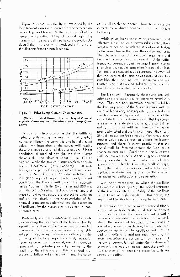
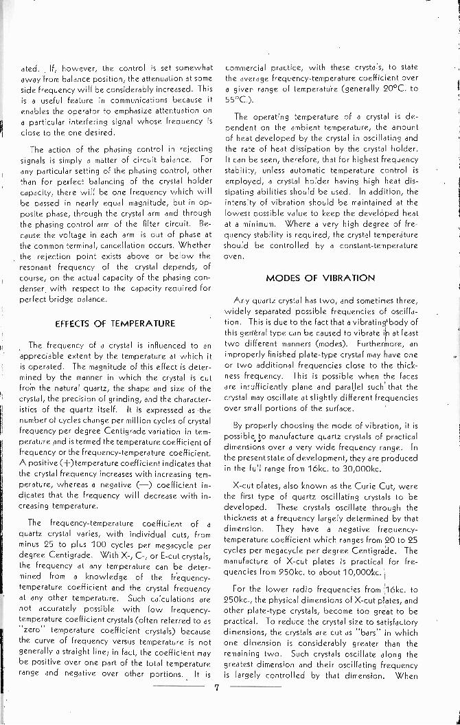
Figure 7 shows how the light developed by thelamp filament varies with current for the two recom-mended types of lamps. At the bottom point of thecurves, representing 0.1 % of normal -light, the
filaments will be very dull red in considerably sub-dued light. If the current is reduced a little more,the filaments become non -luminous.
0
-4
-/60P/40 X50
-/20\-PV.6)
/00 \-OT
AV80
060 A --60LAMP 2.0
MAZDA PILOT40
200.1 02 14 0 (.0 2 0 20 406080
PER CENT LIGHT
Figure 7-Pilot Lamp Current Characteristics
(Data furnished through the courtesy of GeneralElectric Company and Westinghouse Lamp Com-pany)
A common misconception is that the brilliancyvaries directly as the current; that is, at one-halfnormal brilliancy the current is one-half the ratedvalue. An inspection of the curves will readilyshow the extreme error of this assumption. Underconditions of subdued daylight, the 2 -volt lampsshow a dull red glow at about 41 ma. (0.041ampere) while the 6.3 -volt lamps reach this condi-tion at about 75 ma. (0.075 ampere). Half bril-liancy, as judged by the eye, occurs at about 52 ma.with the 2 -volt lamps and 118 ma. with the 6.3 -volt (0.15 ampere) lamps. Under steady currentconditions, the filament will burn out at approxi-mately 100 ma. with the 2 -volt series and 250 ma.with the 6.3 -volt series. It should be realized thatthese current values stated are subject to variationand are not absolute; the characteristics of in-dividual lamps are not identical and the estimationof brilliancy by the human eye is subject to con-siderable error.
Reasonably accurate measurements can be madeby comparing the brilliancy of the filament directlyagainst the brilliancy of a similar lamp connectedin series with a milliammeter and a source of variablevoltage. By adjusting the variable voltage until thebrilliancy of the two lamps is identical, the radio -frequency current will be equal, assuming identicallamps and no radio -frequency by-passing, to thereading of the milliammeter. This is a good pro-cedure to follow when first using lamp indicators
as it will teach the operator how to estimate thecurrent by a direct observation of the filamentbrilliancy.
While pilot lamps serve as an, economical andeffective substitute for a thermo-milliammeter, theselamps must not be considered as foolproof devicesin the same class as thermo-milliammeters and fuses.The characteristics of individual lamps vary andthere will always be some by-passing of the radio-
frequency current around the lamp filament due tostray circuit capacities appearing in parallel with it.To keep these capacities at a minimum, it is essentialthat the leads to the lamp be as short and direct aspossible; that they be well separated and nottwisted; and that they be soldered directly to thelamp base without the use of a socket.
The lamps will, if properly chosen and installed,offer some protection against excessive crystal cur-rent. They are not, however, perfectly reliable;the breaking point of the filaments varies with in-dividual lamps and, most important, the actual cur-rent for failure is dependent on the nature of thecurrent itself. If conditions are such that the currentis rising at a relatively slow rate, the current re-quired for rupture will be close to the figurespreviously stated and the lamp will open the circuit.Should the current be rising at a high rate, a muchgreater value can be reached before the filamentruptures and there is every possibility that thecrystal will be factured before the lamp has a
chance to burn out. Conditions of this latter typewill occur when a crystal is first plugged in a circuithaving excessive feedback, when a radio -fre-
quency surge is fed back into the oscillator stage,during the tuning process in a circuit with too muchfeedback, or during keying of an oscillator whichhas excessive feedback or strong parasitics.
With some transmitters, in which the oscillatoris keyed for radiotelegraphy, the added resistanceof the lamp may affect the ability of the oscillatorto be keyed at high speeds. If this occurs, thelamp should be shorted out 'during transmissions.
It is always best practice in conventional triode,tetrode or pentode crystal oscillators to operatethe circuit such that the crystal current is withinthe maximum safe rating with no load on the oscil-lator. The amount of feedback to the crystal is
controlled, among other factors, by the radio fre-quency voltage across the oscillator tank. At noload this voltage is maximum and, therefore, thecrystal excitation and current will be greatest. If
the crystal current is well under the maximum saferating with no load on the oscillator, there will belittle chance of its becoming excessive with anydegree of loading.
12
The crystal current does not vary in the same
manner with the Tri-tet circuit. With the platetank tuned to the crystal frequency, the crystalcurrent will increase as the oscillator is loaded andwill be maximum at full load. When, however, theplate tank is tuned to some harmonic of the crystal,the crystal current will not vary widely from theno-load value under any degree of loading.
CRYSTAL ACTIVITY
The term "activity" is usually employed in de-scribing, or comparing, the oscillating qualities ofcrystals. The general interpretation of the term issomewhat vague, however, because there has beenno specific definition commonly adopted for it.
Activity is, in the broad sense, the ability of acrystal to oscillate. It is controlled by the type ofcut, the frequency, the precision of grinding, andthe method of mounting. For a given cut, frequency,and holder of good design, the ability to oscillateis dependent on proper grinding. As would beexpected, the power output of a given test oscillatorwill vary widely between crystals of the same fre-quency unless special efforts are made to grind thecrystals with respect to some standard. Originally,crystal activity was determined by comparing thepower output, or the oscillator d.c. grid current,of various crystals in a test oscillator. Crystalsshowing relatively high power outputs had, onthis basis, a high activity.
A power output or d.c. grid current test is notwholly sufficient; an important consideration is
whether the crystals will be positive in startingunder load. If a group of "active" crystals ofapproximately the same frequency is checked in aloaded keyed oscillator, some of the crystals mayaccurately follow the keying while others may lagbehind or refuse to follow at all. The activity of acrystal is most closely associated with its ability tostart rapidly and Bliley Engineers, therefore, haveadopted a definition which includes both poweroutput and keying ability. That definition is:
Activity is the ability of a crystal to start rapidlyand to accurately follow keying in a loaded testoscillator at a given degree of loading.
Activity, when comparing crystals of essentiallyidentical frequencies, is a measure of the effectivecrystal 0; the higher the activity, the higher the Q.To the engineer and amateur, high activity meanshigh frequency stability.
It is impossible to express activity as an exactmathematical quantity because it is only a compara-tive quality. Of course, activity could be specified
by a statement of the minimum keying speed atwhich a crystal will accurately follow the charactersin a definite test oscillator with a given loading.This, however, is significant only in that particulartest circuit since the characteristics of oscillatorcircuits vary. As a manufacturing standard, how-ever, the keyed loaded test oscillator is a valuableinstrument for maintaining high standards of uni-formity and activity. Such instruments are usedregularly in the manufacture of Bliley Crystal Units.
The proper operating conditions for a crystal
controlled oscillator are determined by the relativeactivity of the crystals to be used. A crystal,having a low activity for its particular frequency,can be made to oscillate by adjusting the oscillatorvoltages, the grid bias, and the circuit feedbackfor conditions of maintained oscillation. The fre-quency stability will, however, be relatively poorand the crystal may be sluggish in starting and fol-lowing characters when the oscillator is keyed.
Should a highly active crystal of approximately thesame frequency be substituted, without any circuitchanges, the chances are that the crystal wouldoscillate so vigorously as to shatter itself. This issimply due to the fact that the active crystal is moreeasily excited.
Obviously, a relatively inactive crystal will with-stand considerably more abuse than a highly activecrystal. This, on the surface, might seem to indicatethat low activity is desirable. Such a premise ismost incorrect. With proper operating conditions,the active crystal will follow keying more faithfully,it will provide much better frequency stability andwill give, equal, or better, power output at a
higher circuit efficiency.
The relative activity of quartz crystals varieswith frequency over the practical frequency rangefrom 16kc. to 30,000kc. At 16kc. the activity islowest while maximum activity occurs at about3000kc. Bar -type crystals, which are used in the fre-quency range from 16kc. to 150kc., are relativelysluggish in starting and can be used only in lowpowered oscillator circuits. This is largely due tothe mass of the crystals because their 0 remainshigh (6000 to 18,000). At about 6000kc. theapparent activity starts to fall off due partly to thecharacteristics of the crystals themselves and partlyto the increasing circuit and tube losses as thefrequency is raised.
It is always best practice to take precautionswhen first connecting a crystal, known to have ahigh activity, into a circuit which might cause ex-cessive excitation. This is particularly true wherenew or experimental circuits are being tested.
13
Under such conditions, the comments given in the Care must be exercised, when replacing thesection GENERAL OPERATING NOTES should crystal in its holder; so as not to chip the corners
or to break the crystal by placing it in such a positionthat it will bind. Where both of the crystalelectrodes are separate from the holder assembly,the crystal is merely placed between its two elec-trodesand inserted into the holder cavity; the edgeof the crystal should not protrude beyond the edgeof the electrodes as chipping might result. Itshould be noticed that one face of each electrodeis very finely finished while the other face is rough,in comparison - it is imperative that the finelyfinished faces be in contact with the crystal.
In some types of holders, one electrode is partof the assembly and cannot be removed. Thiselectrode may be slightly larger than the crystal orit may be a small circular 'buttorr. It generallyfits into a recess in the holder body and has a spiralspring beneath it. The button -type holders such asthe Bliley BC3 and HF2, necessitate the exerciseof care in reassembly to prevent binding the crystalwhen the cover electrode is placed in position.If the spiral spring prevents the electrode from seat-ing in its recess, the electrode can be held inposition, for reassembly, by the tip of a screw driver.
In other types of holders, such as Bliley BC6and CM2, the bottom electrode is Fixed and theremovable top electrode is held by a Flat springin the top of the assembly. The spring pressure isadjustable by bending the spring until the desiredtension is obtained. If the second electrode is asmall disc, for use with high -frequency crystals, theposition of the disc electrode, and its pressure,should be determined by experiment for optimumcrystal performance.
be followed.
CRYSTAL CLEANING
Foreign matter on a crystal can cause lerraticperformance or prohibit oscillation entirely. Acrystal will not oscillate if there is any greaie,wax, or similar substance on its faces. Such, sub-
stances are removed during manufacture byfiPecialdegreasing process but can be depticl byhandling of the crystal after manufacture.
Dust is probably the greatest offender. It cancause erratic performance or prevent oscillationentirely. Corona can develop when particles ofdust separate the crystal and its electrodes sincepoints of high potential naturally appear at eachparticle. If the crystal is. subjected to rather highexcitation, a radio -frequency arc can result. The arcwill modulate the oscillator output giving it a roughnote, and, if allowed to continue, the concentratedheat of the arc may fracture the crystal.
To protect the crystals from dust, modern crystalholders are designed to have close -fitting as-
semblies. In addition, each holder is thoroughlywashed before actual use. Sometimes, however,due to handling in shipment, minute particles of dustmay be deposited on the crystal causing non -oscillation. This is more common with very highfrequency crystals for, naturally, they will be moresensitive to foreign matter than crystals at lowerfrequencies. A simple cleaning of the crystal andelectrodes is usually all that is necessary to restorecorrect oscillation; further cleanings generally willbe unnecessary for long periods of service.
The best cleansing agent is carbon tetrachloridebut other solvents such as Carbona Cleaning Fluidmay be used providing they have no dissolved orsuspended impurities. Clean soap and water iseffective but requires greater care as a more vigorousscrubbing action is necessary. The crystal shouldbe carefully washed and then dried with a cleanlint -free cloth. In drying, care should be exercisedto prevent the crystal from becoming entangled inthe cloth and subsequently broken. After clean-ing, the fingers should not be allowed to comeinto contact with the major faces as the oil fromthe fingers will offset the cleaning operation; thecrystal can be handled by grasping it by its edges,or, by employing a pair of tweezers. The same pro-cedure should be followed with the electrodesbut, as they are not fragile and have only one activeface, the operation is considerably simplified.
CRYSTAL CONTROLLED OSCILLATORS
Crystal controlled oscillators have their originin some basic self-excited oscillator arrangement;frequency control is brought about by connectinga quartz crystal into the circuit in such a mannerthat the crystal becomes the frequency determiningelement. The conventional triode or pentodecrystal oscillator, as shown in figures 8 and 13, ismerely the well-known tuned -plate tuned -gridcircuit with a quartz crystal substituted for thegrid tank. For purposes of discussion, such circuitsare sometimes called tuned -plate crystal -grid oscil-lators.
Oscillator circuits are remarkably self-regulating;the circuit values can be varied over wide rangesand the oscillator will continue to function. Withany set of component values which do not prohibitoscillation entirely, the various currents and gener-,
14
ated voltages will distribute therrselves for bestperformance under those conditions. Of course,there are circuit values which will give optimumperformance and efficiency; but, for practical ap-plications, these require no great consideration.Representative components are generally chosenand then, by cut -and -try methods, the most satis-factory values determined.
The crystal controlled oscillator is equally self-re_gulating, and, for that particular reason, it re-
qwres more care in design and operation. AoJartz crystal, as previously explained, has mechani-cal limitations in that an excessive vibration ampli-t,de will cause the crystal to be shattered. It is
necessary to design a crystal controlled oscillatorsuch that the circuit, in attempting to correct forvarying operating conditions, will not cause thecrrstal excitation to become excessive. This con-sideration necessitates a reasonably careful choiceof circisit values and, in addition, limits crystal,--,,tnol to comparatively low powered oscillators.
Tne crystal excitation in the usual type of oscil-lator crrc i t depends on the amplification factor ofthe tube, the bias, the d.c. operating potentials,the circuit feedback, and the activity of the crystal.Fr,r a qr /en power output, the tube with thehll'iest amplification factor will generally require?he, bast encitation (lowest crystal current). This is
i-l.'ediatelv apparent in the performance of pentodeis'4l oscillators as compared to triode oscillators;
s- je.or, sod tubes, having the highest amplificationfar_ rexp)tre much lass crystal excitation for a
ion pc, wer Output.8e.a, power tubes are excellent crystal
due to the very small amount of ex-, 04.ior, required for full output. In the con-
tp,tr,,erk r r ist4I oscillator circuit, good out -1,4 performance are easily obtained. Where
tiro tube performs AS a combination crystal oscillator,,,,d fre,,,,,,,ency multiplier, however, beam -powert.,bes such as the 61.6 have a strong tendency to-ward the development of parasitics, especially atthe higher freoirentie.s This is due to the powersensitivity and to the fact that the screen grid in such1,)10, is not fill!, effenhve at radio frequencies.
the r1!41 ensmatitio in a particular oscillatoris detrmiried by the r.f voltage across the
tars ficause this vrAtage. is applied to, , the e.r ttaliori naturally will
4, as, as qiir r I tail- WAP49e is raised. The
ill4fr)r lank dflefirlhet itsat.d, 4s Ole rotrr, i, iri(rralvd, the r f
-.4,1tage trasiiriably high L4,, r fif11/41,10. 101 I FterltrAr
',/'101111 4 vier 1411,/ i5 better
with triode tubes. The greater internal plate-tc-grid capacity and the low amplification factor ofmost triodes, requires that the tank voltages belimited such that the crystal excitat on will notbecome excessive. This applies also to the cathodetank of the Tri-tet circuit because the oscillatingportion is a tricde.
The feedback in conventional tuned -plate
crystal -grid oscillators is brought about by theinternal plate-tc-grid capacity of the tube. The
excitation requirements of active quartz crystalsare so small that, even with screen -grid tubes, thisinternal capacity is usually sufficient to bring aboutample excitation of all but low frequency crystals.Some tubes, such as the 802 and RK23, have verylow internal capacities and a small amount of ex-ternal feed -back capacity is recommended by themanufacturer. Most active crystals above 1500kc.will oscillate without the addition of the externalcapacity; every effort should be made to operatethe circuit without the added capacity before anyattempt is made to increase the feedback. Excessive
feedback, whether through the intentional use ofa condenser or through the presence of stray circuitcapacities, will bring about high excitation andendanger the crystal. With screen -grid tubes,
proper by-passing of the screen grid is essential. If
the by-passing is inadequate, the grid will assumean r.f. potential greatly increasing the feedbackto the crystal.
The bias on the tube is an important considera-tion. In general, the higher the bias the greaterwill be the crystal current and the power output.Beyond certain limits, however, an increase in biaswill cause a considerable increase in crystal
current with only a small gain in power output.Too much bias can bring about excessive excitation.
Bias is most generally obtained by the use of agrid -leak resistor, a cathode resistor, or a com-bination of both. With grid -leak bias, an increaseof resistance will he accompanied by an increasein the crystal current. Also, the crystal starts
oscillating under conditions of zero bias with acontinually increasing bias as the crystal excitationbecomes greater. This means that the crystal cur-rent will be greatest when the oscillator Is notloaded because the plate tank voltage, and tht bias,will be highest under that condition. As a resultof the zero bias in a non -oscillating condo!, ,n, thecrystal may be hard starting and may notespecially when a low value resistor is
By retorting 1,, , 1,1,41, the crystal wilr ;Hooscillating under lovorable conditi,,IC, Ihrinitial bias provided I y hi 1111 ricethe effective plate Inr/11,1, I. Mill wikt
15

brings about a grid condition more conducive tothe starting of oscillation. Too much bias of thistype, however, will produce the opposite effect;the crysta,1 will be hard starting and the currentwill be high. The correct value of cathode resistorgenerally lies between 200 and 500 ohms, 350ohms being a good all-around value.
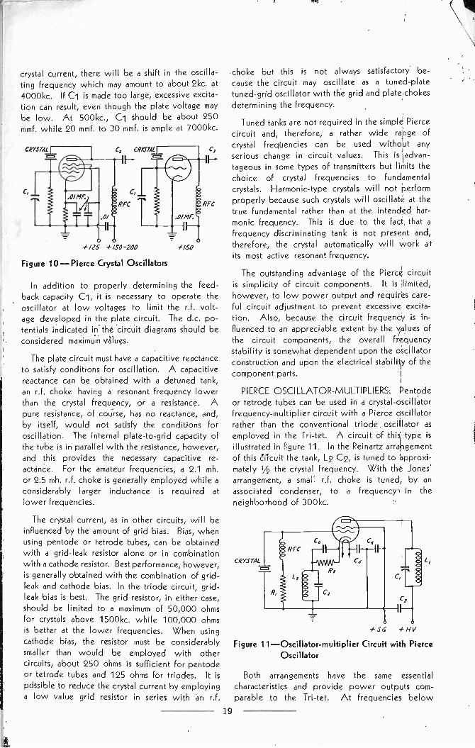
With pentode or tetrode type tubes, best per-formance usually is obtained by combining grid -leak and cathode bias. In general, the grid -leakresistor should not be higher than 20,000 ohmswhile the cathode resistor will lie between thevalues already given. It is customary practice toinsert an r.f. choke in series with the grid -leakresistor so as to offset the low impedance otherwisepresented to the crystal. This procedure is recom-mended where the grid resistor has a vaiue of lessthan 50,000 ohms. Standard quality multiple -pie2 mh-. to 3 mh. chokes are excellent for frequenciesabove 1500kc.
When using triode tubes in the tuned -platecrystal -grid circuit with high frequency crystals, itis best to connect an r.f. choke directly across thecrystal to provide a path to ground for the d.c.grid current, and then employ cathode bias ex-clusively. The addition of a grid resistor usuallywill greatly increase the crystal current withouteffecting a corresponding increase in power output.
The d.c. plate voltage on an oscillator will,naturally, influence the crystal excitation. As thepotential is raised, the developed r.f. voltage willincrease bringing about additional excitation. Withpentode and tetrode type tubes the screen -gridvoltage becomes an important factor; the higherthis voltage the greater will be the crystal currentand the power output.
Crystal activity is an equally important factor inthe design of crystal oscillator circuits. This subjecthas been fully discussed in the section entitledCRYSTAL ACTIVITY and need not be repeated.
Circuit losses must be properly considered inthe design of a crystal oscillator. The circuitshould be carefully arranged so that there will bea minimum of stray feed -back capacities which mayincrease the crystal excitation. It is readily possible,with improper layout, to fracture a crystal becauseof additional feedback brought about by straycircuit capacities. If any appreciable couplingexists between the oscillator and other stages ofthe transmitter working at the same frequency, thecrystal excitation may easily be increased to anexcessive amount; thorough inter -stage shielding inhigh power transmitters is imperative. At thehigher frequencies, especially above 6000kc., the
16
tank circuit should be well constructed and prefer-ably made self-supporting. If coil fornli are used,these should be of the best quality. TI-' copperwire in the tank inductance should be sificientlylarge to carry the circulating tank current, for, if thewire is too small, the resultant losses will effect a
considerable decrease in power output. Whenthe cathode of the oscillator tube is operated at an
r.f. potential, the heater leads should be by-passedto ground at the tube socket.
While it is often desirable to obtain relativelyhigh power outputs from crystal oscillators, itshould be remembered that a crystal oscillator is
fundamentally a frequency controlling stage; the"heart" of a transmitter. With the present lowcost of tubes, it is much better to work the crystaleasily by using a low powered oscillator andadding an additional tube to obtain sufficient driv-ing power for the following stages. This assuresgood frequency stability and removes the danger ofcrystal failure through excessive excitation in anattempt to obtain sufficient power output.
TRIODE OSCILLATORS: The conventional tri-ode crystal oscillator is shown in figure 13. It isa universal circuit because it performs well withcrystals at all frequencies. Cathode bias, as
indicated, is best for crystals above 1500kc. whilegrid -leak bias is preferable at lower frequencies.The proper cathode resistor varies with differenttype tubes but normally will be between 200 and500 ohms. Grid -leak bias, in addition to cathodebias, is recommended only for low frequencies.
A relatively low L to C ratio tank should beemployed for best stability and reduced crystalcurrent. The d.c. plate potential directly in-
fluences the crystal current and the voltage, there-fore, should not be too high. Some tubes may beoperated at potentials up to 350 volts while withothers, the potential must be limited to 250 voltsor less. In any event, maximum safe potential for3ny individual triode oscillator will depend on theamplification factor of the tike, the bias and thetank L to C ratio.
SC
Figure 8-Pentode Crystal Oscillator+HV
The dual -triode crystal -oscillator frequency -multiplier is an excellent arrangement for frequencymultiplying. This circuit is shown in figure 14.Although the tank circuit values are given for 10 -
and 5 -meter operation, the circuit can be adaptedfor any crystal frequency by choosing the correcttank constants. If it is desired to use the secondsection as a buffer at the crystal frequency, neutrali-zation must be incorporated. This is necessary toprevent feedback into the oscillator. The maximumoscillator plate voltage for tubes such as the 6E6and RK34, is 325 volts while tubes such as the 53and 6A6 may be operated with a maximum of 350volts. It is best practice, however, to limit theplate voltage of the oscillator section of all dual -
triode circuits ko a maximum of 300 volts; themultiplier section can be operated at a highervoltage if greater harmonic output is desired.
Because the excitation requirements of most triodetubes are quite high, their power output as crystaloscillators is relatively low under conditions ofsafe crystal current. Power outputs of up to 5watts are normal with the usual type of triodetube at frequencies above 1000kc. In the dual -triode circuit the power output, when frequencydoubling, is in the neighborhood of 31/2 watts.
PENTODE AND TETRODE OSCILLATORS:The conventional pentode or tetrode crystaloscillator is the most practical and commonlyemployed circuit. A representative pentodeoscillator is diagrammed in figure 8. The generalcharacteristics of pentode and tetrode oscillatorsare identical inasmuch as the essential differencebetween the tubes lies in the method of suppressingsecondary emission from the plate.
A combination of grid -leak and cathode biasgives the most satisfactory results with all crystalsabove 1500kc. The correct value for the gridresistor usually will be between 5000 and 20,000ohms, while the cathode resistor will be from200 to 500 ohms. A representative combinationfor most pentode and tetrode tubes is a 20,000ohm grid resistor and a 350 ohm cathode resistor.At low frequencies, best performance is gener-ally obtained with simple grid -leak bias.
The screen -grid voltage has a considerablygreater influence on the crystal current than theplate voltage. A potential of 250 volts is generallymaximum for normal plate potentials while a lowervalue is preferable when the plate potential isgreater than 400 volts. Proper by-passing of thescreen grid is important, especially so with beam -power tubes. The by-pass condenser, preferablyof the mica type, should be placed directly at thetube socket. With pentode tubes, where the sup-
pressor grid is connected to one of the baseterminals, an increase in power output can beaccomplished by operating the suppre'Ssor grid ata low positive voltage.
Pentode and tetrode tubes, having a high ampli-fication Factor, will provide the greatest poweroutput for a given crystal current. Furthermore,the frequency stability with such tubes is muchbetter than obtainable in the conventional triodeoscillator due to the action of the screen grid.This grid reduces the internal plate -to -grid feed-back and also has a compensating action on thetube impedance under conditions of changingpower supply voltages. With tubes such as theRK23, 802 and 807, which are designed specifi-cally for use at radio frequencies, power outputsof 10 to 15 watts can be obtained at frequenciesabove 1000kc. with a reasonably low crystal current.
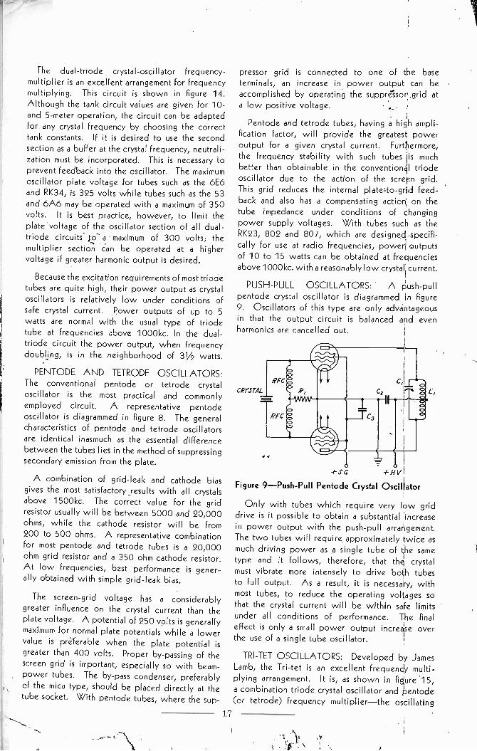
PUSH-PULL OSCILLATORS: A push-pullpentode crystal oscillator is diagrammed in figure9. Oscillators of this type are only advantageousin that the output circuit is balanced and evenharmonics are cancelled out.
+SG +HV
Figure 9-Push-Pull Pentode Crystal Oscillator
Only with tubes which require very low griddrive is it possible to obtain a substantial increasein power output with the push-pull arrangement.The two tubes will require approximately twice as
much driving power as a single tube of the sametype and it follows, therefore, that the crystalmust vibrate more intensely to drive both tubesto full output. As a result, it is necessary, withmost tubes, to reduce the operating voltages sothat the crystal current will be within safe limitsunder all conditions of performance. The finaleffect is only a small power output increase overthe use of a single tube oscillator.
TRI-TET OSCILLATORS: Developed by JamesLamb, the Tri-tet is an excellent frequency multi-plying arrangement. It is, as shown in figure '15,a combination triode crystal oscillator and pentode(or tetrode) frequency multiplier-the oscillating
17
portion is a triode with the screen grid serving asthe plate. By inserting the tuning tank in sqieswith the cathode, the screen grid is grouncliid tor.f. At the same time, some regeneration results atharmonic frequencies by reason of the fact thatthe common tank circuit carries currents at boththe crystal and the harmonic frequencies.
Since the oscillating portion of the Tri-tet is a
triode, the usual consideration of employing a lowL to C ratio applies to the cathode tank. Forlowest crystal current and highest output at har-monics, the tank should be tuned to a frequencyconsiderably higher than that of the crystal. Asa matter of fact, the circuit should not be operatedwith the cathode tuned close to the crystal fre-quency for the result will be high crystal currentand decreased output. For proper results, the tankshould be tuned for greatest power output at theparticular harmonic without serious regard to therelation between cathode' tuning and d.c. platecurrent.
For each particular type of tube there will bean optimum cathode- tank L to C ratio. This is
discussed by James Lamb in the April,. 1937 issueof OST magazine. In general, the higher themultiplying factor employed, the higher should bethe cathode, L to. C ratio. If the capacicy-7-is- toohigh, the voltage drop at the harmonic frequencywill be low and regeneration will, therefore, besmall. Likewise, if high stray circuit capacity is
allowed across the crystal, regeneration will belowered. When a Tri-tet is to be used both'formultiplying and working straight through, it should.be noted that the best cathode tank L to C ratiofor multiplying is too high when working straightthrough/ the low C can bring about high crystalcurrent and, possibly, cause fracturing of the
crystal. When the plate tank is operated at thecrystal frequency, the use of a high -C cathode tank'is essential.
It will be seen that, as far as r.f. is concerned,the cathode and plate tanks are in series. For thisreason, when the plate tank is tuned to the crystalfrequency, the crystal current will be lowest atno load and will increase with loading. The crystalcurrent, when frequency multiplying, remains sub-stantially constant with loading because the oscil-lator portion then functions nearly independentlyof the remainder of the circuit.
A condition of decreased power output at thesecond harmonic can exist if the cathode tank shouldhappen to be tuned to that frequency. This con-dition is obviously corrected by slightly retuningthe cathode tank.
- -
Since the screen grid t erves as the plate of thecrystal oscillator, the screen -grid d.c. potential willinfluence the crystal Arrent to a large extent. Apotential of 250 volts is considered maximum,while a lower value is preferable. The properbias conditions are somewhat different from
a simple triode oscillator due to the fact that thebias also influences the power output on harmonics.In general, bias recommendations given for thepentode and tetrode crystal oscillators should befollowed with the Tri-tet.
The effectiveness of the screen grid in tubesemployed as Tri-tet oscillators requires con-sideration. If the shielding is poOr at radio fre-quencies, -`the circuit should be used only forfrequency multiplying-this is most important withcrystal frequencies much 'above 3000kc. Whenpoor internal shielding ;does exist, the crystal ex-citation can become excessive as a result of addi-tional feedback when the plate tank is tuned tothe crystal frequency. Tubes such as the 802 andRK23 have excellent radio frequency characteristicswhile others, such as the 6L6, 6F6, 2A5, 42, 59and" 89, are poorly shielded since they weredesigned vimarily- for use at audio frequencies.When operating at the crystal frequency, especiallywith pborly shielded tubes, it is best practice toconvert the circuit to a conventional pentode ortetrode oscillator by shorting out the cathode tank.This is easily accomplished by bending the tips ofthe cathode condenser rotor plates such that the
-0, condenser can be shorted out simply by rotating it tofull capacity position.
The Tri-tet has excellen't frequency stabilityinasmuch as the coupling 1lDetween the oscillatorand the output circuit is brought about electron-ically within the tube. The power output, whenoperating straight through with a suitable tube suchas the 802 or RK23 and at a crystal frequencyabove 1000kc., is in the neighborhood of 12 watts.When frequency doubling, it is about 8 watts.
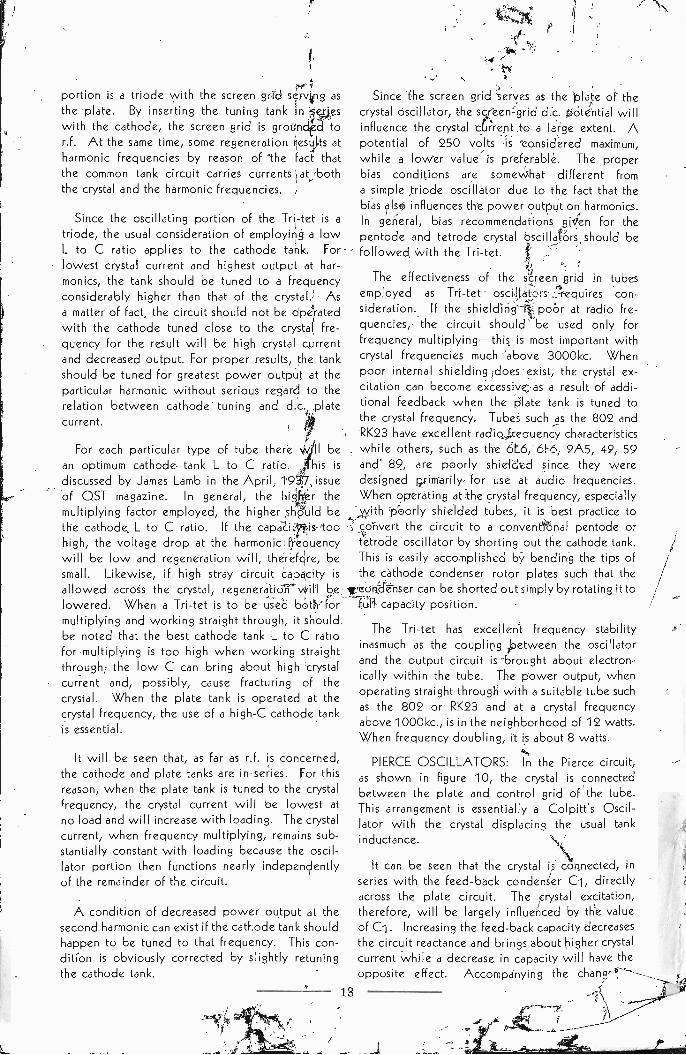
PIERCE OSCILLATORS: In the Pierce circuit,as shown in figure 10, the crystal is connectedbetween the plate and control grid of the tube.This arrangement is essentially a Colpitt's Oscil-lator with the crystal displacing the usual tank
inductance.
It can be seen that the crystal is connected, inseries with the feed -back condenser Ci, directlyacross the plate circuit. The crystal excitation,therefore, will be largely influenced by the valueof C1. Increasing the feed -back capacity decreasesthe circuit reactance and brings about higher crystalcurrent while a decrease in capacity will have theopposite effect. Accompanying the
18
crystal current, there will be a shift in the oscilla-ting frequency which may amount to about 21<c. at4000kc. If C1 is made too large, excessive excita-tion can result, even though the plate voltage maybe low. At 500kc., Ci should be about 250mmf. while 20 mmf. to 30 mmf. is ample at 7000kc.
*125 *150-200
Figure 10-Pierce Crystal Oscillators
*150
In addition to properly determining the feed-back capacity C1, it is necessary to operate theoscillator at low voltages to limit the r.f. volt-age developed in the plate circuit. The d.c. po-tentials indicated in the circuit diagrams should beconsidered maximum values.
The plate circuit must have a capacitive reactanceto satisfy conditions for oscillation. A capacitivereactance can be obtained with a detuned tank,an r.f. choke having a resonant frequency lowerthan the crystal frequency, or a resistance. Apure resistance, of course, has no reactance, and,by itself, would not satisfy the conditions foroscillation. The internal plate -to -grid capacity ofthe tube is in parallel with the resistance, however,and this provides the necessary capacitive re-acteince. For the amateur frequencies, a 2.1 mh.or 2.5 mh. r.f. choke is generally employed while aconsiderably larger inductance is required at
lower frequencies.
The crystal current, as in other circuits, will beinfluenced by the amount of grid bias. Bias, whenusing pentode or tetrode tubes, can be obtainedwith a grid -leak resistor alone or in combinationwith a cathode resistor. Best performance, however,is generally obtained with the combination of grid -
leak and cathode bias. In the triode circuit, grid-
leak bias is best. The grid resistor, in either case,should be limited to a maximum of 50,000 ohmsfor crystals above 1500kc. while 100,000 ohmsis better at the lower frequencies. When usingcathode bias, the resistor must be considerablysmaller than would be employed with othercircuits/ about 250 ohms is sufficient for pentodeor tetrode tubes and 125 ohms for triodes. It is
pOssible to reduce the crystal current by employinga low value grid resistor in series with an r.f.
choke but this is not always satisfactory. be-cause the circuit may oscillate as a tuned -platetuned -grid oscillator with the grid and plate chokesdetermining the frequency.
Tuned tanks are not required in the simple Piercecircuit and, therefore, a rather wide range ofcrystal freqbencies can be used without anyserious change in circuit values. This is advan-
tageous in some types of transmitters but limits thechoice of crystal frequencies to fundamental
crystals. Harmonic -type crystals will not performproperly because such crystals will oscillate at thetrue fundamental rather than at the intended har-monic frequency. This is due to the fact that afrequency discriminating tank is not present and,therefore, the crystal automatically will work atits most active resonant frequency.
The outstanding advantage of the Pierce circuitis simplicity of circuit components. It is limited,however, to low power output and requires care-ful circuit adjustment to prevent excessive excita-tion. Also, because the circuit frequency is in-fluenced to an appreciable extent by the values ofthe circuit components, the overall frequencystability is somewhat dependent upon the oscillatorconstruction and upon the electrical stability of thecomponent parts.
PIERCE OSCILLATOR -MULTIPLIERS: Pentodeor tetrode tubes can be used in a crystal -oscillatorfrequency -multiplier circuit with a Pierce oscillatorrather than the conventional triode oscillator asemployed in the Tri-tet. A circuit of this type isillustrated in figure 11. In the Reinartz arrangementof this circuit the tank, L2 C2, is tuned to approxi-mately 1/2 the crystal frequency. With the Jones'arrangement, a small r.f. choke is tuned, by anassociated condenser, to a frequency in the
neighborhood of 300kc.
+SC +NV
Figure 11-Oscillator-multiplier Circuit with PierceOscillator
Both arrangements have the same essentialcharacteristics and provide power outputs com-parable to the Tri-tet. At frequencies below
19

4000kc., the cathode capacity C2 may have anysuitable value from 100 mmf. to 250 mmf. Thecircuits are quite critical at higher frequencies,however, and the value of C2 becomes an im-portant factor. For each type of tube, tank L to Cratio, degree of loading, and crystal, there is an
optimum value of C2 which will give greatestpower output consistent with good circuit stability.If C2 is smaller than the critical capacity, there willbe a strong tendency to develop parasitics, especi-ally with beam -power tubes, and the crystalcurrent will be high. In fact, it is possible for theparasitics to become sufficiently intense to fracturea crystal. Capacities greater than the critical valuewill result in lowered crystal current and decreasedpower output.
C2 should preferably be a variable conden-ser with a maximum capacity of about .00025mf. In any event, the actual amount of capacity inuse should be no less than .0001 mf. and, even thensuch a low value should be employed only whenfrequency multiplying. Representative values are.00015 mf. when multiplying and .00025 mf. whenworking straight through. In some instances, itmay be necessary to increase the capacity to as
much as .0005 mf. for proper performance.
In addition to influencing the crystal current andcircuit stability, C2 affects the power output atharmonics. At the higher harmonics, greatest poweroutput is obtained with low values of C2. It mustbe remembered, however, when operating thecircuit at a harmonic with a very low value of C2,that the capacity must be increased when changingto fundamental operation-the conditions for bestharmonic output are not generally satisfactory forfundamental operation and excessive excitationmay result. The importance of carefully determin-ing the proper operating value of C2 for crystalfrequencies above 4000kc. cannot be too stronglyemphasized.
The oscillator portion of this circuit, like thesimple Pierce circuit, has no positive choice ofcrystal frequency. Harmonic type crystals, there-fore, normally will oscillate at the fundamentalrather than the calibrated frequency. With theproper value for C2, however, a harmonic crystalcan be caused to work at its intended frequency bytuning the plate tank to that frequency; at all othersettings, the crystal will oscillate at its fundamentalfrequency.
When the output tank is tuned to the fundamentalcrystal frequency, the operating characteristics aresimilar to the Tri-tet; that is, the crystal current riseswith load and excessive feedback can result when
tubes with insufficient internal shielding are em-ployed for working straight through.
The bias considerations for the Pierce circuit ingeneral, apply to the oscillator portion of thesearrangements. For frequency multiplying, a com-bination of grid -leak and cathode bias generallyresults in best performance.
An improvement in circuit performance can berealized by adding a small amount of externalcapacity directly between the oscillator control-grid and cathode. This capacity is equivalent toCl in figure 10 and stabilizes the crystal feedback.The amount of capacity added, however, should bemuch smaller in order to prevent excessive crystalexcitation and to avoid a reduction of harmonicoutput. About 10 mmf. to 15 mmf. is sufficient at7000kc. In general, the value of C2 (figure 11)should be raised somewhat when the additionalfeedback is applied to an existing oscillator.
Grid -cathode feedback is particularly advanta-geous when variable frequency crystals, such as theBliley VF1, are to be used in the oscillator. Thepresence of the feedback helps to offset the fallingoff of effective crystal activity as the crystal fre-quency is raised. The result is decreased poweroutput variation over the full adjustable frequencyrange and better keying at high frequency settings.
MODIFIED PIERCE OSCILLATORS: A uniquemodification of the Pierce oscillator is shown infigure 12a. It will be noticed that the circuit hasthe same components as the Pierce oscillator -multiplier (figure 11) but the screen grid is tied tothe control grid. As a matter of fact, any triodetube can be used but, by using a pentode tubein this manner, a high -mu triode is formed suchthat the plate current is nearly zero with the circuitnon -oscillating. When the crystal goes into oscil-lation, the plate current will rise to normal opera-ting value.
Excitation of the crystal is brought about by ther.f. drop across L2C2. This tank is, in the samemanner as in the Pierce oscillator-multiplier(figure11), tuned to a frequency considerably lower thanthat of the crystal. The crystal will tend to oscillatealmost independently of the tuning of LiCi (byshorting out L1C1, the circuit becomes a simplePierce oscillator). Output will be developed when
Ci is tuned to the crystal frequency or, with aharmonic -type crystal, to the intended harmonicoscillating frequency. With fundamental oscillatingcrystals, frequency multiplying can be accomplishedby tuning to any harmonic of the crystal frequency.
An increase in power output can be broughtabout by by-passing the screen grid and applying
20
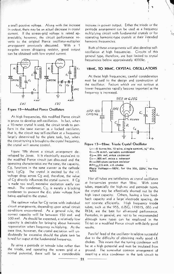
a small positive voltage. Along with the increasein output, there may be an actual decrease in crystalcurrent. If the screen -grid voltage is raised ap-preciably, however, the circuit performance re-
verts to the original Pierce oscillator -multiplierarrangement previously discussed. With a 1
megohm screen dropping resistor, good outputcan be obtained with low crystal current.
1-/V
(a) (h)-,LHV
Figure 12-Modified Pierce Oscillators
At high frequencies, this modified Pierce circuitis prone to develop self -oscillation. In fact, whena 10 -meter crystal is used, the circuit tends to per-form in the same manner as a locked oscillator;that is, the circuit may self -oscillate at a frequencylargely determined by the plate tank, but, whenthe circuit tuning is brought to the crystal frequency,the crystal will assume control.
Figure 12b shows a circuit arrangement de-veloped by Jones. It is electrically equivalent tothe modified Pierce circuit just discussed and theoperating characteristics are the same; the capacity,C2, functions in the same manner as the cathodetank, L2C2. The crystal is excited by the r.f.voltage drop across C2 and, therefore, the valueof C2 directly influences the crystal current. If C2is made too small, excessive excitation easily canresult. The condenser, C3, is merely a blockingcondenser to prevent the d.c. plate voltage frombeing applied to the crystal.
The optimum value for C2 varies with individualcircuit arrangements, depending upon actual circuitconditions encountered. As a general rule, thecorrect capacity will lie between 150 mmf. and500 mmf. As should be expected, a relatively lowcapacity is desirable for bringing about harmonicregeneration when frequency multiplying. At thesame time, however, the crystal excitation will un-doubtedly be excessive should the plate tank betuned for ouput at the fundamental frequency.
By using a pentode or tetrode tube rather thanthe triode, and operating the screen grid at anormal potential, there will be a considerable
increase in power output. Either the triode or thepentode arrangement can be used as a frequencymultiplying circuit with fundamental crystals or foroperating harmonic -type crystals at their intendedharmonic frequencies.
Both of these arrangements will also develop self -oscillation at high frequencies. Circuits of thisgeneral type, therefore, are best limited to crystalfrequencies below approximately 4000kc.
18MC. TO 30MC. CRYSTAL OSCILLATORS
At these high frequencies, careful considerationmust be paid to the design and construction ofthe oscillator. Factors which are not serious atlower frequencies rapidly become important as thefrequency is increased.
955 OR GJSG
1-/F2- 10ACRYSTAL
Figure 13-28mc. Triode Crystal OscillatorLt -8 turns No. 12 wire, single spaced, 34" dia.C1-75 mmf. variable condenserC2-.005 mf. mica cndenserC3--.005 mf. mica c ndenserRI -200 ohm carbon resistorRFC X2.5 m h. r.f. chokePlaLe Voltage -180V. for the 955, 220V. for the6J5G
Not all tubes are satisfactory as crystal oscillatorsat frequencies greater than 18mc. With sometubes, especially the high -mu and pentode types,the crystal may be effectively shorted out by thehigh input capacity. Others, having a low feed-back capacity and a large electrode spacing, donot operate efficiently. High frequency triodetubes, such as the 955, 6J5G, HY615, 6E6 andRK34, are the best for all-around performance.Pentodes, in general, are not to be recommendedalthough some types can be employed in theTri-tet or a modified Pierce circuit with fairly goodresults.
Parallel feed of the oscillator is seldom successfuldue to the difficulty of obtaining really good r.f.chokes. This means that the tuning condenser willbe at a high potential and must be insulated fromground. The somewhat common arrangement ofinserting a mica condenser in the tank circuit to
21

block the d.c. voltage so that the tuning condensercan be grounded is not particularly satisfactory,mica condensers have appreciable losses at veryhigh frequencies and, if used to carry circulatingtank current, there may be a serious drop in poweroutput.
All r.f. leads must, obviously, be short anddirect. By-pass and tank condensers should beof the best quality. To minimize tank circuit losses,the coil should be self-supporting and wound withheavy copper wire or tubing. Use nothing smallerthan number 12 wire.
The low plate impedance of the recommendedtriode tubes necessitates the use of a high -C tankfor maximum power output. Along with the in-creased output, the high C greatly improves thecircuit stability; in fact, pentode stability is ap-proached when the proper tank values are chosen.The cathode tank of the Tri-tet must also have arelatively high C, inasmuch as the oscillating por-tion is a triode.
Circuits designed for use with 18mc. to 30mc.crystals are shown in figures 13, 14, and 15. Thecircuits are basically conventional but all componentvalues should be followed as these have beenfound to give the best output and stability. Theoscillator tank -inductances are specified For 10-
meter crystals, but for other high frequencies, it is
only necessary to choose appropriate coils. Withthe simple triode oscillator a 955 tube will provideabout 13/4 watts output while approximately 21/2watts can be obtained with the 6J5G. Either ofthese tubes will produce sufficient output to drivean 802, RK23, 807, RK39 or 6L6 tube as a buffer.or doubler.
The dual -triode circuit is advantageous for fre-quency multiplying. As a matter of fact, a singleRK34 ,with a 10 -meter crystal, forms an excellentlow power 5 -meter transmitter. A 6E6 tube willsupply an output of about 3 watts on 5 meters witha 10 -meter crystal while the RK34 will give about31/2 watts. The types 53 and 6A6 tubes are notcomparable for output or performance.
An 802 or RK23 tube can be used in the Tri-tetcircuit as shown. The output on 5 meters is ap-proximately 21/2 watts with the 802 and 31/2 wattswith the RK23, a slightly greater output can beobtained by applying up to 45 volts positive tothe suppressor grid. The 6L6 and 6L6G beam -power tubes are not particularly recommended be-cause their poor internal shielding causes thedevelopment of parasitics which are difficult toeliminate.
22
SHIELD
Figure 14-Dual-Triode Oscillator -Doubler For56mc. Output
LI -6 turns No. 12 wire, single spaced, 34" dia.C1-75 mmf. variable condenserL2 -4 turns No. 12 wire, double spaced, g" dia.C2 - 35 mmf. variable condenserC3 - .0001 mf.. mica condenserC4, C5-.005' mf. mica condenserRFC -2.5 mh. r.f. choke 1RI -400 ohmsR2-30,000 ohmsPlate Voltage- 6E6 -3001RK34 -325
For higher power output than obtainable with atriode oscillator, an oscillator -multiplier circuitarrangement similar to one/ of thOse previouslydescribed (figures 11 and 12) might be used. By
tuning the plate tank to the crystal frequency, theresulting regeneration inherent in the circuit offsetssome of the circuit and tube losses such that pentodeor tetrode tubes can be employed with fairlysatisfactory results. Frequency multiplying, whenusing harmonic -type crystals, is, of course, notfeasible due to the fact that such crystals willoscillate at their intended Frequencies only whenthe plate tank is tuned accordingly.
In most cases, the use of a regenerative oscillatoris best avoided where transmitter design permitsthe incorporation of a simple triode circuit. Whilesatisfactory performance can be realized with aregenerative circuit, the complete elimination ofself -oscillation and high crystal current is difficult,particularly with beam -power tubes.
The E -cut- crystal, which it employed for fre-quencies above 23mc., has a frequency -temperaturecoefficient of +43 cyclet/mc./°C. To avoidobjectionable frequency drift where temperaturecontrol is not applied to the crystal, the oscillatortube should be operated at the lowest plate voltageconsistent with requiredcpower output. This
minimizes crystal heating and subsequent frequencydrift. Where a low grid -drive tube such as the807 or 614 follows the oscillator, an oscillatorcl:c. plate potential of 100 or 125 volts is adequateif efficient coupling exists between the two stages.With such a reduced plate voltage, direct crystalheating is quite low. Possible heating of the
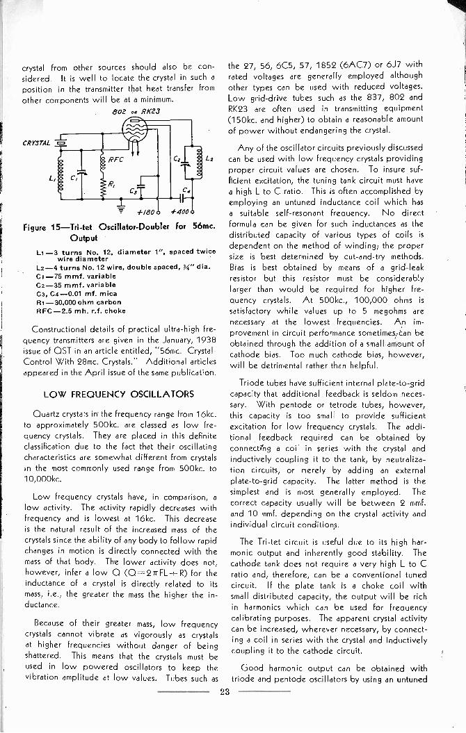
crystal from other sources should also be con-sidered. It is well to locate the crystal in such aposition in the transmitter that heat transfer fromother components will be at a minimum.
802 OR RK23
CRYSTAL
+180 #400
Figure 15-Tri-tet Oscillator -Doubler for 56mc.Output
Li -3 turns No. 12, diameter 1", spaced twicewire diameter
L2-4 turns No. 12 wire, double spaced, g" dia.C1-75 mmf. variableC2-35 mmf. variableC3, Ca -0.01 mf. micaR1-30,000 ohm carbonRFC -2.5 mh. r.f. choke
Constructional details of practical ultra -high fre-quency transmitters are given in the January, 1938issue of OST in an article entitled, "56mc. Crystal -Control With 28mc. Crystals." Additional articlesappeared in the April issue of the same publication.
LOW FREQUENCY OSCILLATORS
Quartz crystals irr the frequency range from 16kc.to approximately 500kc. are classed as low fre-quency crystals. They are placed in this definiteclassification due to the fact that their oscillatingcharacteristics are somewhat different from crystalsin the most commonly used range from 500kc, to10,000 kc.
Low frequency crystals have, in comparison, alow activity. The activity rapidly decreases withfrequency and is lowest at 16kc. This decreaseis the natural result of the increased mass of thecrystals since the ability of any body to follow rapidchanges in motion is directly connected with themass of that body. The lower activity does not,however, infer a low 0 (0= -271 -FL-÷- R) for theinductance of a crystal is directly related to itsmass, i.e., the greater the mass the higher the in-ductance.
Because of their greater mass, low frequencycrystals cannot vibrate as vigorously as crystalsat higher frequencies without danger of beingshattered. This means that the crystals must beused in low powered oscillators to keep thevibration amplitude at low values. Tubes such as
the 27, 56, 6C5, 57, 1852 (6AC7) or 6J7 withrated voltages are generally employed althoughother types can be used with reduced voltages.Low grid -drive tubes such as the 837, 802 andRK23 are often used in transmitting equipment(150kc. and higher) to obtain a reasonable amountof power without endangering the crystal.
Any of the oscillator circuits previously discussedcan be used with low frequency crystals providingproper circuit values are chosen. To insure suf-ficient excitation, the tuning tank circuit must havea high L to C ratio. This is often accomplished byemploying an untuned inductance coil which hasa suitable self -resonant frequency. No directformula can be given for such inductances as thedistributed capacity of various types of coils is
dependent on the method of winding; the propersize is best determined by cut -and -try methods.Bias is best obtained by means of a grid -leakresistor but this resistor must be considerablylarger than would be required for higher fre-quency crystals. At 500kc., 100,000 ohms is
satisfactory while values up to 5 megohms arenecessary at the lowest frequencies. An im-provement in circuit performance sometimes can beobtained through the addition of a small amount ofcathode bias. Too much cathode bias, however,will be detrimental rather than helpful.
Triode tubes have sufficient internal plate-to-Bridcapacity that additional feedback is seldom neces-sary. With pentode or tetrode tubes, however,this capacity is too small to provide sufficientexcitation for low frequency crystals. The addi-tional feedback required can be obtained byconnecting a coil in series with the crystal andinductively coupling it to the tank, by neutraliza-tion circuits, or merely by adding an externalplate -to -grid capacity. The latter method is thesimplest and is most generally employed. Thecorrect capacity usually will be between 2 mmf.and 10 mmf. depending on the crystal activity andindividual circuit conditions.
The Tri-tet circuit is useful due to its high har-monic output and inherently good stability. Thecathode tank does not require a very high L to Cratio and, therefore, can be a conventional tunedcircuit. If the plate tank is a choke coil withsmall distributed capacity, the output will be richin harmonics which can be used for frequencycalibrating purposes. The apparent crystal activitycan be increased, wherever necessary, by connect-ing a coil in series with the crystal and inductivelycoupling it to the cathode circuit.
Good harmonic output can be obtained withtriode and pentode oscillators by using an untuned
23

tank. The higher the L to C ratio, the greaterwill be the harmonic output. Also, the higherthe grid -leak resistance, the more distorted will bethe output and, thereby, the greater the harmonicstrength.
In conventional triode, tetrode or pentodeoscillator circuits with grid -leak bias, maximum
output occurs when the circuit is tuned for mini-mum plate current. This point is, however, un-stable and operation must be below it on thelow C side(tank tuned towards a higher frequency).For best performance, the circuit should beoperated, whether the tank is tuned or untuned,at the lowest plate current consistent with positivestarting of the crystal. With low frequency crystals,this generally will occur at 50% to 60% of themaximum drop in plate current which can occur bytuning.
A circuit often used in frequency standards, andparticularly recommended for use with Bliley lowtemperature -coefficient crystals from 85kc. to 150kc., is the modified Colpitt's Oscillator shown in fig-ure 16. This arrangement has a relatively low poweroutput but is exceptional for frequency stability.The crystal is connected directly into the fre-quency determining tank where it serves as a filterelement. When the tank is tuned to a frequency at,or close to, the resonant frequency of the crystal,the crystal will assume control by reason of thefact that its impedance is lowest at its resonantfrequency and rises very rapidly for other nearbyfrequencies. The crystal will maintain control overa comparatively large tuning range of the tank but,beyond that range, it no longer controls the oscil-lations, serving only as a series condenser in thetank circuit.
/MEG
Figure 16-Standard Frequency Oscillator
The oscillating frequency of the circuit, withthe crystal assuming control, can be variedover a limited range by the tuning condenser.At 100kc. this amounts to about ±8 cycles whichis sufficient to correct for any frequency changeswhich might result from aging of the circuit com-ponents or from moderate variations in operating
24
temperature. Any receiver -type pentode tube,such as the 6J7, is satisfactory for use in this circuitbut the 1852 (6AC7) is particularly recommendedbecause of its high transconductance.
The circuit values shown in the diagram aresuitable for frequencies from 20kc. to 300kc. L
and C should be of such values that, with the crystalshorted out, the circuit can be made to oscillateat a frequency slightly below the resonant fre-quency of the crystal at the approximate mid -positionof the tuning condenser. The exact L to C ratio is notextremely critical but it does affect the frequencystability. Greatest frequency stability will occurwith a fairly low L to C ratio because the crystalimpedance can then rapidly become large in pro-portion to the reactance of L if there is any tendencyof the circuit frequency to deviate appreciablyfrom the resonant frequency of the crystal. Ofcourse, as the L to C ratio is lowered, the rangeover which the circuit frequency can be adjustedis also decreased. A net operating tank capacity ofabout 85 mmf. (working value, 170 mmf. persection) is best for crystals at 100kc. and gives atotal frequency range of about 16 cycles. If thefrequency range appears to be too large with anycrystal, reduce the L to C ratio; and, conversely,if a greater frequency range is desired (at theexpense of frequency stability), the L to C ratiocan be increased.
The modified Colpitt's Oscillator is not parti-cularly suitable for frequencies much above 300kc.As the frequency is increased, it becomes moredifficult to keep the circuit locked -in' with thecrystal - the circuit will have a strong tendencyto self -oscillate at other frequencies and the tuningrange of the condenser over which the crystalassumes control becomes increasingly narrowed.Also, since the crystal is required to carry thecirculating tank current, the circuit power must,of a necessity, be kept at a low level.
The modified Pierce circuit, shown in figure 12b,is excellent for low frequencies because of thepositive feedback afforded. This arrangement isrecommended particularly for use with low driftcrystals from 150kc. to 400kc. A self -resonantinductance can be used for purposes of circuitsimplicity but, where design permits, it is preferableto employ a conventional tuned tank.
It is characteristic of the bar -type crystals em-ployed for low frequencies to possess two definitemodes of vibration: the intended length oscillationand a thickness vibration. When the bars aremounted without mechanical restriction, such as infixed or variable air -gap holders, either mode ofoscillation can be excited by tuning the oscillator

circuit to either frequency. This property is utilizedin dual frequency calibrator crystal units (BlileySMC100, 100kc.-1000kc.). If the bar is clamped,
say between knife edges, the thickness mode often
can be completely discouraged such that, in effect,
it becomes non-existent.
The two possible oscillating frequencies of freelymounted bar -type crystals are generally so wellseparated that the correct frequency, in a 'single'frequency crystal, is easily identified and no con-fusion results. In some circuit arrangements,
however, where self -resonant tanks are employed,conditions can be encountered whereby the thick-ness rather than the length frequency will be ex-cited. Particularly troublesome is the situationwhere the crystal frequency will start at one valueand then hop to the other during operation. In
any case of this nature, the performance can becorrected by increasing the size of the self -resonantcoil or by placing fixed capacity in parallel with it.The effect of either alternative is, of course, to tunethe oscillator toward the desired frequency and,simultaneously, detune it away from the thicknessfrequency of the crystal. Representative values ofthe plate coil and condenser for a simple Piercecircuit to operate at frequencies from 150kc. to400kc. are 10 mh. to 16 mh. (single pi r.f. choke)and 400 mmf. In the same circuit, the grid -to -cathode feed -back capacity should be in the orderof 150 mmf.
OSCILLATOR KEYING
Crystal oscillators, operating at all but very lowfrequencies, can be directly keyed for radio-telegraphy. Keying is accomplished in a variety ofmanners, although interruption of the cathodecircuit is most common. Other methods includebreaking the primary circuit of the oscillator powersupply, opening the screen -grid circuit with pen-tode or tetrode tubes, applying high negative biasto the suppressor grid of pentodes, control -gridblocking, and shorting or opening the crystal circuit.
To prevent "chirping" when keying to the oscil-lator, the screen. grid potential for tetrode orpentode tubes should be obtained by means of a
voltage divider rather than a series dropping resistor.This prevents the existence of high screen -gridvoltage at the instant the key is depressed. Whenkeying in the cathode circuit, best results areobtained when the cathode of both the oscillatorand the first buffer are simultaneously interrupted.The two cathode leads can be tied together beyondtheir individual biasing resistors and r.f. by-passcondensers such that the key can be connectedbetween the common lead and ground. A key
click filter is ordinarily necessary whether one orboth cathode circuits are keyed but, usually, theuse of a condenser and resistor in series across the
key terminals is sufficient (C, 1/4 to 2 mfd.; R, 200to 20,000 ohms). If further filtering is necessary,
a choke with an inductance of from 1 to 5 henries
can be connected in series with the keying circuit.The choke should, of course, be relieved of r.f.
An effective but not commonly employed keyingsystem consists of directly shorting the crystal or ofopening one crystal connection. Either arrange-ment naturally requires the use of a keying relaylocated close to the crystal such that very shortconnecting leads can be realized. When the crystalis to be shorted, a good quality mica condenserwith a capacity of .002 mf. or greater should beconnected in series with the crystal circuit to pre-vent disturbance of normal bias conditions in theoscillator.
Keying can also be effected by control -gridblocking; that is, through the application of a highnegative voltage to the control grid when the keyis open. Unless the keying bias is high and can beapplied instantly, however, clean characters may notresult. This is caused by the fact that an increaseof bias generally will be accompanied by highercrystal excitation and some increase in output. If
the bias change is not instantaneous, the output mayincrease momentarily before dropping to zero uponopening of the keying contacts. In addition, if thetime of full application is sufficiently slow (causedby delay in resistance -capacity combinations), thecrystal might be fractured as a result of operationunder a,,high bias condition. Suppressor -gridblocking has less influence on crystal performancebut, in the Tri-tet and similar circuits, the crystal willcontinue to oscillate when the key is open. This
may or may not be undesirable, depending uponindividual operating conditions.
Low frequency crystal oscillators (below 200kc.)cannot be satisfactorily keyed at reasonable speedsbecause of the relatively slow rate at which thecrystal goes into oscillation. Also, at very highfrequencies, it often is difficult to obtain a signalentirely free from chirping. Either of these dif-ficulties can be eliminated in a multi -stage trans-mitter by keying one or more of the intermediatestages and allowing the crystal oscillator to runcontinuously. Under such conditions, the abilityof the crystal to follow keying has no bearing ontransmitter performance. Furthermore, if a bufferstage exists between the oscillator and the keyedstages, small changes in operating frequency (chirp-ing) caused by varying oscillator loading underkeying are eliminated. In this respect, it should be
25

noted that oscillator circuits such as the Tri-tet(figure 15) and the Pierce oscillator -multiplier(figure 11) possess some buffering action by virtueof the electronic coupling existing betWeen theoscillator proper and the output circuit.
An objection to keying stages other than theoscillator lies in the fact that a local radiation mayexist from the continuously running portion of thetransmitter. This is undesirable for break-in opera-tion or for local monitoring and can be eliminatedonly by thorough shielding of the radiating stagesor by remote control of the transmitter. Also,unless the transmitter is carefully designed andadjusted, a back wave may be transmitted.
Figure 17 illustrates a method whereby thedesirable features of direct oscillator keying andof inter -stage keying can be combined. This system,like simple inter -stage keying, is excellent for highspeed telegraphy even with sluggish crystals. Anadded feature, however,, is that the oscillator is
'dead' during the time the key is open.
TO OSC.
TRANSMITTER
INTER -STAGE
/ST OR 2,0BUFFER
Figure 17-Double-Action. Keying Circuit
Referring to the diagram, it will be seen that,when the key is open, the cathode circuit of thekeyed interstage is incomplete and the crystaloscillator is inoperative because the crystal circuitis shorted to ground. Upon depressing the key,the oscillator is permitted to function but a signalis not transmitted until the relay contacts completethe cathode circuit of the additionally keyed stage.The time interval introduced by the relay allows thecrystal oscillation to approach full operating valuebefore a signal is radiated by the transmitter. Thistime delay reduces the possibility of a ragged signaldue to slow crystal starting, or chirping due tochanging oscillator loading. As in simple inter -
stage keying, it is desirable, of course, to have atleast one buffer stage between the oscillator andthe keyed amplifier.
The time delay is adjustable by the relay contactspacing and should be set at the minimum value
consistent with clean characters. Naturally, therelay should be well designed such that bouncingof the contacts will not occur. If oscillator controlis obtained by crystal shorting as shown in thediagram, the leads to the relay contacts, particularlyfrom the oscillator, must be very short. Underproper conditions of adjustment and operation, thetransmitted characters can be made to approach a
square wave in characteristics without the pres-sence of disturbing keying transients which wouldotherwise normally occur.
It is not necessary, incidentally, to key theoscillator by crystal shorting as shown. By the useof appropriate relay contacts or multiple relays, theoscillator can be keyed by any other desirablemethod. The primary consideration is to introducea time interval between the starting of the oscillatorand the actual transmission of a signal.
The oscillator arrangement in the Bliley Vari-X8,is an example of circuit design for clean keyingcharacteristics and very low crystal excitation withreasonable power output. Figure 18 shows thewiring diagram of the oscillator and indicates correctvalues for 40 -meter and 80 -meter crystals. Throughthe use of the high transconductance 6AC7 tube inconjunction with proportioned control -grid andscreen -grid feedback, excellent keying ability is
realized. At the same time, essentially constantpower output occurs with variable frequencycrystals over the adjustable frequency range andthe power output at 40 meters is nearly the samewhether a 40 -meter crystal be used or an 80 -metercrystal be employed for doubling to 40 meters.
Figure
HEY RELAY *300 VOLTS
18-Vari-X Oscillator Circuit
Ri -20,000 ohmsR2-150 ohmsR3-20,000 ohmsR4-100,000 ohmsRs -30,000 ohmsCI -.000015 mf., mica
ZZ =Mc.
C2 - .01 mf.C3-.00015 mf., micaC4-.1 mf.Cs-.01 mf.C6-.000140 mf., variableC7 -.01 mf., mica
Li, Lz, L7 -2.1 mh. r.f. choke*L3-26 T. No. 18 enamel, 1 W' D., space wound*L4- 5 T. No. 18 enamel, 1k," D., space wound
*For 80 and 40 meters (3500kc.-7500kc.)
8Registered U. S. Patent Office
26

In general, when a crystal oscillator is to bekeyed, the oscillator should be considerably de -tuned from resonance and operated with a rela-tively light load. If the oscillator is loaded heavilyand tuned for maximum output, chirping and skip-ping of characters can result.
FREQUENCY STANDARDS
Early frequency standards were simply variabletuned circuits, known as wavemeters. These in-struments were calibrated against the output of arotary high -frequency alternator whose frequency,and its harmonics, was determined from the con-stants of the machine and its speed of rotation - atthat time, the alternator was the only source ofaccurate calibrating frequencies. The wavemeteris subject to considerable error and, even withpresent precision manufacturing and calibratingfacilities, the dependable accuracy is in the neigh-borhood of only 0.1% to 0.25%. While thewavemeter does have a definite place in radioengineering, its inherent inaccuracies are far toogreat for frequency standardization purposes.
The first true standards of frequency wereelectrically excited tuning forks. These forks weremaintained in vibration by a regenerative vacuum -tube oscillator circuit and were temperature con-trolled to provide the highest degree of frequencystability. Frequency was determined by direct refer-ence to the basic element, time, through the mediumof connecting a synchronous motor -driven clock tothe output of the oscillator circuit and comparing thetime, as indicated by that clock, with true time as de-termined by astronomical observatories such as theU. S. Naval Observatory. The average frequencyof the tuning forks was then calculated from thetime -rate of the oscillator clock. The fundamentalaccuracy of the tuning -fork standard could be heldwithin about 7 parts in one million (0.0007%)which is far greater accuracy than obtainable withwavemeters. For frequency measurement purposes,the output of the tuning -fork oscillator was multi-plied by vacuum -tube frequency multipliers to pro-duce a series of standard frequencies.
The development of the quartz oscillating crystalentirely changed the conception of practical fre-quency stability and accuracy. Quartz crystals,having a large equivalent inductance and a high0, possess a degree of frequency stability un-attainable with other types of oscillator frequencycontrol; the oscillating frequency is almost entirelydetermined by physical dimensions, it is unaffect-ed by magnetic fields or gravity, and is influencedto only a very small extent (much less than witha tuning fork) by variations in atmospheric pressure.
Furthermore, a quartz crystal has the physical,chemical and electrical stabilities which are obviousprerequisites for permanance in a frequency
standard.
Frequency standards are divided into two classifi-cations: (1) primary standards of frequency and,(2) secondary standards of frequency. The primary
standard, as its name implies, is a fundamental
standard against which all other frequency de-terminations are made. It is an independentstandard because it is checked for accuracy andstability by direct measurements against time. Quartzcrystal control has so simplified the construction offrequency standards that primary standards are
commercially practicable and are regular equipmentin many laboratories, schools and governmentbureaus. The secondary standard has no pro-visions for checking its frequency directly withtime and it, therefore, must be calibrated by refer-ence to some primary standard.
PRIMARY STANDARDS OF FREQUENCY
Fundamentally, a primary standard of frequencyconsists of a temperature controlled crystal oscil-lator, a series of multivibrators for subdividing theoscillator frequency, and a synchronous motor -driven clock. The oscillator frequency may be20kc., 30kc., 50kc. or 100kc., but 50kc. is morecommon. The crystal temperature is held to withina maximum variation of 0.01 degree Centigradein a heated chamber while the oscillator circuitcomponents are temperature controlled to a lesserdegree. No provisions are made in commercialinstruments to eliminate the effects of varyingatmospheric pressure but, in the high precisioninstruments maintained by the U. S. Bureau ofStandards, the crystals are operated at a substantiallyconstant pressure in glass enclosed chambers.
The oscillator frequency is subdivided by multi -vibrators to provide a series of standard frequenciesand to obtain a suitable low frequency for drivingthe synchronous motor clock. Since the time asindicated by the clock is entirely dependent onthe frequency of the exciting current, and sincethe driving frequency is derived from the crystaloscillator, the clock actually serves as a counterfor the number of oscillator cycles which occurin a given passage of time. By comparing the clocktime with true time, the average frequency of theoscillator can be determined. The time comparisoncan be made to within a very small fraction of asecond and the oscillator frequency, therefore, canbe known within close limits of absolute.
The frequency of commercial primary standardscan be held to within 2 parts in 10 million
27
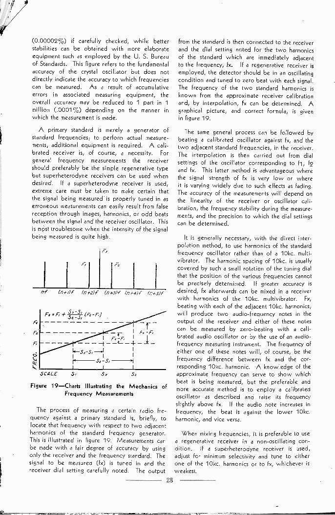
(0.00002%) if carefully checked, while betterstabilities can be obtained with more elaborateequipment such as employed by the U. S. Bureauof Standards. This figure refers to the fundamentalaccuracy of the crystal oscillator but does notdirectly indicate the accuracy to which frequenciescan be measured. As a result of accumulativeerrors in associated measuring equipment, theoverall accuracy may be reduced to 1 part in 1million (.0001%) depending on the manner inwhich the measurement is made.
A primary standard is merely a generator ofstandard frequencies; to perform actual measure-ments, additional equipment is required. A cali-brated receiver is, of course, a necessity. Forgeneral frequency measurements the receivershould preferably be the simple regenerative typebut superheterodyne receivers can be used whendesired. If a superheterodyne receiver is used,
extreme care must be taken to make certain thatthe signal being measured is properly tuned in aserroneous measurements can easily result from falsereception through images, harmonics, or odd beatsbetween the signal and the receiver oscillator. Thisis most troublesome when the intensity of the signalbeing measured is quite high.
(7,
Fz
of (n4uf (n #2)1 lni-3)C 074-411 (n+sh'
SCALE .5, Sx
Figure 19-Charts Illustrating the Mechanics ofFrequency Measurements
The process of measuring a certain radio fre-quency against a primary standard is, briefly, tolocate that frequency with respect to two adjacentharmonics of the standard frequency generator.This is illustrated in figure 19. Measurements canbe made with a fair degree of accuracy by usingonly the receiver and the frequency standard. Thesignal to be measured (fx) is tuned in and thereceiver dial setting carefully noted. The output
28
from the standard is then connected to the receiverand the dial setting noted for the two harmonicsof the standard which are immediately adjacentto the frequency, fx. If a regenerative receiver isemployed, the detector should be in an oscillatingcondition and tuned to zero beat with each signal.The frequency of the two standard harmonics is
known from the approximate receiver calibrationand, by interpolation, fx can be determined. Agraphical picture, and correct formula, is givenin figure 19.
The same general process can be followed bybeating a calibrated oscillator against fx, and thetwo adjacent standard frequencies, in the receiver.The interpolation is then carried out from dialsettings of the oscillator corresponding to f1, 12and fx. This latter method is advantageous wherethe signal strength of fx is very low or whereit is varying widely due to such effects as fading.The accuracy of the measurements will depend onthe linearity of the receiver or oscillator cali-bration, the frequency stability during the measure-ments, and the precision to which the dial settingscan be determined.
It is generally necessary, with the direct inter-polation method, to use harmonics of the standardfrequency oscillator rather than of a 10kc. multi -
vibrator. The harmonic spacing of 10kc. is usuallycovered by such a small rotation of the tuning dialthat the position of the various frequencies cannotbe precisely determined. If greater accuracy is
desired, fx afterwards can be mixed in a receiverwith harmonics of the 10kc. multivibrator. Fx,
beating with each of the adjacent 10kc. harmonics,will produce two audio -frequency notes in theoutput of the receiver and either of these notescan be measured by zero -beating with a cali-brated audio oscillator or by the use of an audio -frequency measuring instrument. The frequency ofeither one of these notes will, of course, be thefrequency difference between fx and the cor-responding 10kc. harmonic. A knowledge of theapproximate frequency can serve to show whichbeat is being measured, but the preferable andmore accurate method is to employ a calibratedoscillator as described and raise its frequencyslightly above fx. If the audio note increases infrequency, the beat is against the lower 10kc.harmonic, and vice versa.
When mixing frequencies, it is preferable to usea regenerative receiver in a non -oscillating con-dition. If a superheterodyne receiver is used,
adjust for minimum selectivity and tune to eitherone of the 10kc. harmonics or to fx, whichever isweakest.
If fx is below the fundamental frequency of the
standard, or if it is higher than the usable harmonicsof the standard and the multivibrator, a calibrated
oscillator, termed a frequency meter or heterodynefrequency meter, must be employed. The frequency
of this instrument is set such that it is equal to someharmonic of fx, or such that fx is some harmonic of
the frequency meter. -Then the procedure is to
measure the frequency of the frequency meter anddetermine the value of fx by multiplying or dividingthat value by the harmonic number. It is, of course,
necessary to know the approximate frequency offx so that the harmonic order can be determined.This can be done with a wavemeter or by determin-ing several successive frequencies which will giveharmonics or sub -harmonics at fx. If fx is lowerthan the frequency meter, fx will be equal to the
difference between any two successive frequencymeter settings. Should fx be higher, its frequencywill be nf, where n is a harmonic number and f thereading of the frequency meter. It also followsthat fx will be equal to (n-I-1)fi, (n+2)12,(n+3)13, etc. where f1, f2 and f3 are successivefrequencies of decreasing values whose harmonicsare equal to fx. Therefore, nf=--(n+1)11 or,
f1n= - where n is the harmonic order for Ire--flquency f (the higher of the two successive fre-
quency meter frequencies).
The frequency meter, the receiver (heterodynedetector) and the audio. oscillator (interpolationoscillator) are regular equipment for a completeprimary standard frequency measuring assembly. In
practically all cases the measurements are made asdescribed and herewith summarized for a completeaccurate measurement: (1) determine the approximate value of fx by interpolation with the frequencymeter, (2) set the frequency meter such that its
fundamental, harmonic or sub -harmonic frequencyis at zero beat with fx, (3) mix the output of thefrequency meter and of the 10kc. multivibrator in areceiver, (4) measure one of the audio frequenciesproduced in the output of the receiver by means ofthe interpolation oscillator and, (5) calculate fx fromall known values. To determine whether themeasured audio beat is produced against the upperor lower 10kc. harmonic, it is necessary only toslightly raise the frequency of the frequency meter.The audio note will increase if the beat is with thelower harmonic or it will decrease if the beat isagainst the upper harmonic.
SECONDARY STANDARDSOF FREQUENCY
Any previously calibrated frequency determin-ing instrument is a secondary standard of frequency.
Through common usage, however, secondary
standards are considered to be crystal controlledoscillators of high stability employed for frequencymeasurements:
Secondary standards are used where the extremeprecision and flexibility of the primary standard
is not required and more simplified equipment isadequate. They have no provision for directlydetermining frequency and must be both calibratedand checked against some primary standard. Whenthe fundamental frequency is appropriate, secondarystandards can be checked directly against the trans-missions of stations offering standard frequencyservices. The outstanding station of this type isWWV, the U. S. Bureau of Standards, whichtransmits on frequencies of 5000kc., 10,000kc.and 20,000kc. with an accuracy of better than1 part in 5 million.
The primary standard, less the timing equipment,is a secondary standard. If the frequency stabilityneed not be extremely high the constant tempera-ture oven can be simplified or dispensed withentirely. The associated frequency measuring
equipment can be complete for all types of measure-ments or abbreviated for specific applications. Asimple 100kc. or 1000kc. crystal controlled oscil-lator in conjunction with a calibrated receiveror a calibrated frequency meter is often adequate
and gives better accuracy than could be obtainedwith precision wavemeters. Whether the equip-ment is complete or reduced to essentials, measure-ments are wholly or partially made in accordancewith one of the methods outlined in PRIMARYSTANDARDS OF FREQUENCY.
The frequency monitors used in transmitting
stations to check the operating frequency or
frequencies are secondary standards. They are de-signed for one, or a group of, particular frequenciesand the measurements are, therefore, considerablysimplified. Some frequency monitors, especiallythose for use in broadcasting stations, are directreading in terms of cycles per second deviationfrom the assigned value.
Secondary standards are useful in any applicationdealing with radio frequencies. With the increas-ing complexity of modern radio receiving equip-ment, radio servicemen find that the usual type ofcalibrated service oscillator is not sufficiently ac-curate for precision alignments. Through the use ofa standard frequency oscillator in conjunction withthe service oscillator, frequency accuracy of align-ments can be greatly increased and better receiverperformance assured. Harmonics of the standardcan be directly employed for accurately checkingdial calibrations since there will be a series of
29

harmonics over each band at a frequency spacingequal to the fundamental frequency of the oscil-lator. Up to about 4000kc. a fundamental fre-quency of 100kc. is excellent while a 1000kc.fundamental is to be preferred for the higherfrequencies.
Figure 20-100kc.-1000kc. Standard FrequencyOscillator with High' Harmonic Out-put
L -8 mh. r.f. choke (for 100kc.)Lt -single pie of 2.5 mh. or 2.1 mh. r.f. choke
(for 1000kc.)C1-100 mmf. trimmer condenser
NOTE: For a modulated signal, connect theoscillator plate circuit to the input of the powersupply filter. With a full -wave rectifier, this willgive 120 cycle modulation (60 cycle supply). Toprevent frequency modulation, the screen -gridshould always be fed with d.c.
For alignment of the intermediate frequencystages, the service oscillator is set to the inter-mediate frequency by interpolation between 100kc.harmonics. This is best performed by picking upa harmonic of the service oscillator in the broad-cast band of any suitable receiver. Suppose theintermediate frequency is 460kc. Set the serviceoscillator to 460kc. by its calibrated dial and pickup the second harmonic (920kc.) in a receiver.Note the dial settings for two adjacent 100kc.harmonics (900kc. and 1000kc.) and, by inter-polation, determine the correct dial setting for920kc. Then set the oscillator such that its secondharmonic falls at the dial setting corresponding to920kc. Or, beat the output (2nd harmonic) of theservice oscillator with the 900kc. and 1000kc.standard harmonics in a receiver and note the oscil-lator dial settings. By interpolation, the correctoscillator dial setting for 460kc. can be calculated.For better accuracy, a 10kc. multivibrator may beemployed. This, however, is generally unnecessary.If the intermediate frequency is such that one ofits harmonics falls at an even 100kc. (such as 450kc.x 2=--900kc.), interpolation will be unnecessarybecause the oscillator harmonic can then be set tozero beat with the proper standard frequency.
The Bliley type SMC100 crystal unit was de-signed especially for service work. It contains a
30
specially ground crystal which will oscillate ateither 100kc. or 1000kc. and, in a simple inex-pensive circuit, gives dependable accuracy. Thecircuit and recommended values are shown infigure 20.9
Amateurs will find a 100kc. secondary standardto be a most valuable instrument for locating theedges of the bands and subdividing them into100kc. points. Any amateur expecting to operateclose to the edge of a frequency band should,by all means, have a method of accurately checkingfrequency to make certain that operation is withinthe legal requirements. The secondary standardcan be easily and economically constructed with aBliley SOC100, SOC100X or SMC1009 100kc.Standard Frequency Crystal Unit.
The type SOC100 crystal unit is well suitedfor primary or secondary standards of frequencyfor it incorporates a low temperature -coefficientbar -type crystal mounted between knife edges.The crystal is calibrated for use in the Colpitt'sCircuit shown in figure 16 and discussed in LOWFREQUENCY OSCILLATORS. To insure bestperformance and accuracy, a correctly designedtank coil (L) is an integral part of the unit. Thecapacity C should be a dual 350 mmf. tuning con-denser. The output at 100kc. is approximately1.5 volts R.M.S. and the harmonics will be usableup to the 30th or greater, depending on the sen-sitivity of the receiving equipment employed.
For greater output and higher harmonics fromthe secondary standard, one or two untunedamplifier stages should follow the oscillator. These,as shown in figure 21, are simply resistance -coupledamplifiers with r.f. chokes in series with the plateand grid -coupling resistors, and biased to give adistorted output. The r.f. chokes cause the amplifiergain to increase somewhat with frequency thereby
.00/ Mr.
RFC
00/AM:.00/AfF
RFC RFC
+/80 -200 /00 -/50 #180-250
Figure 21 -Resistance -Coupled Amplifiers For usewith Standard Frequency Oscillatorsand Multivibrators
RFC -2.1 mh. to 60 mh.Ri -50,000 ohms to 500,000 ohmsR2-1500 ohms to 4000 ohmsR3 - 5000 ohms to 100,000 ohms
9 Refer to Engineering Bulletin E-7 for completedetails on construction and application
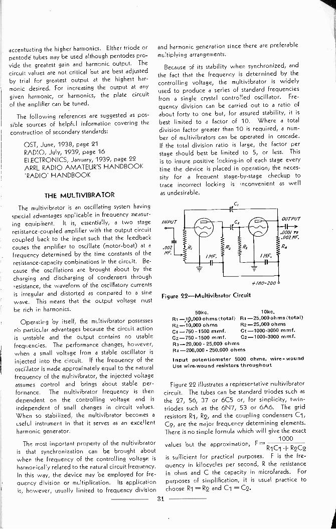
accentuating the higher harmonics. Either triode or
pentode tubes may be used although pentodes pro-
vide the greatest gain and harmonic output. The
circuit values are not critical but are best adjusted
by trial for greatest output at the highest har-
monic desired. For increasing the output at any
given harmonic, or harmonics, the plate circuit
of the amplifier can be tuned.
The following references are suggested as pos-sible sources of helpful information covering the
construction of secondary standards:
QST, June, 1938, page 21RADIO, July, 1939, page 16ELECTRONICS, January, 1939, page 22ARRL RADIO AMATEUR'S HANDBOOK'RADIO' HANDBOOK
THE MULTIVIBRATOR
The multivibrator is an oscillating system having
special advantages applicable in frequency measur-
ing equipment. It is, essentially, a two stageresistance -coupled amplifier with the output circuitcoupled back to the input such that the feedback
causes the amplifier to oscillate (motor -boat) at afrequency determined by the time constants of the
resistance -capacity combinations in the circuit. Be-
cause the oscillations are brought about by thecharging and discharging of condensers throughresistance, the waveform of the oscillatory currentsis irregular and distorted as compared to a sinewave. This means that the output voltage must
be rich in harmonics.
Operating by itself, the multivibrator possessesno particular advantages because the circuit actionis unstable and the output contains no usablefrequencies. The performance changes, however,when a small voltage from a stable oscillator is
injected into the circuit. If the frequency of theoscillator is made approximately equal to the naturalfrequency of the multivibrator, the injected voltageassumes control and brings about stable per-
formance. The multivibrator frequency is then
dependent on the controlling voltage and is
independent of small changes in circuit values.When so stabilized, the multivibrator becomes auseful instrument in that it serves as an excellentharmonic generator.
The most important property of the multivibratoris that synchronization can be brought aboutwhen the frequency of the controlling voltage isharmonically related to the natural circuit frequency.In this way, the device may be employed for fre-quency division or multiplication. Its applicationis, however, usually limited to frequency division
and harmonic generation since there are preferable
multiplying arrangements.
Because of its stability when synchronized, and
the fact that the frequency is determined by thecontrolling voltage, the multivibrator is widelyused to produce a series of standard frequenciesfrom a single crystal controlled oscillator. Fre-
quency division can be carried out to a ratio ofabout forty to one but, for assured stability, it is
best limited to a factor of 10. Where a total
division factor greater than 10 is required, a num-ber of multivibrators can be operated in cascade.If the total division ratio is large, the factor perstage should best be limited to 5, or less. This
is to insure positive locking -in of each stage everytime the device is placed in operation; the neces-sity for a frequent stage -by -stage checkup totrace incorrect locking is inconvenient as well
as undesirable.
/NPUT
°-1.002MF.
c,
/ MF.
/80-200
Figure 22-Multivibrator Circuit
OUTPUT
000 1002
R4
50kc. 10kc,Ri -19,000 ohms (total) Ri -25,000 ohms (total)R2-10,000 ohms R2-25,000 ohmsCI -750 -1500 mmf. CI -1000-3000 mmf.C2-750 - 1500 mmf. C2 -1000-3000 mmf.R3-20,000 - 25,000 ohmsR4-200,000 - 250,000 ohms
Input potentiometer 5000 ohms, wire -woundUse wire -wound resistors throughout
Figure 22 illustrates a representative multivibratorcircuit. The tubes can be standard triodes such asthe 27, 56, 37 or 6C5 or, for simplicity, twin -triodes such as the 6N7, 53 or 6A6. The gridresistors R1, R2, and the coupling condensers C1sC2, are the major frequency determining elements.There is no simple formula which will give the exact
values but the approximation, F -1000
R2C2is sufficient for practical purposes. F is the fre-quency in kilocycles per second, R the resistancein ohms and C the capacity in microfarads. For
purposes of simplification, it is usual practice tochoose Ri = R2 and Cl ---- C2.
31
in the diagram, is shown as a potentiometerand a fixed resistor in series. The potentiometer,which has a value of 5000 ohms, offers a simplemethod of injecting the controlling voltage andregulating its value. In the formula given Rishould be the total value of the two resistancesin series.
Other than grid circuit injection as illustrated,the controlling voltage can be inserted in the platecircuit. A common method for accomplishing thisis to include a portion of either, or both, plateresistors in the output circuit of the driving source.The resistor, common to both the driver and themultivibrator, provides the necessary coupling.Naturally, a by-pass condenser should not appearat the coupling point for such would decrease, orpossibly destroy, the function of the couplingresistor. An equivalent alternate method forinjection is to magnetically couple a coil in thedriver output to a coil in series with either one, orboth, of the multivibrator plate resistors.
There is a difference in the controlling actionof the injected voltage depending on whetherthe frequency ratio is an odd or even number.This is due to the phase relationship between theinjected voltage and the multivibrator oscillations.In general, a multivibrator, which has symmetricalcomponents and is symmetrically fed (control volt-age applied equally to both tubes), has the strongesttendency for operation at even ratios. If thesymmetry is destroyed, the circuit functions betterat odd ratios. The symmetry can be disturbed bychoosing unequal circuit values for the two tubesor by the simple expedient of injecting the controlvoltage into the circuit of only one tube. Thissuggests the use of a snap switch for connecting thecontrol voltage optionally to one or both of thetubes where a single multivibrator is intended towork at more than one frequency. For practicalpurposes, however, satisfactory control at eitherodd or even ratios can be obtained by choosingthe value of one plate resistor 10 to 50 times greaterthan the other.
Either the grid -coupling condensers or the grid -coupling resistors should be made variable so thatthe multivibrator can be adjusted to the correctfrequency. The use of variable condensers is
most practical and these are shown in the diagram.Should it be inconvenient to obtain adjustablemica condensers of the proper capacities, thelargest available sizes may be used in parallel withappropriate fixed condensers.
To adjust the multivibrator, the input controllingvoltage is reduced to zero and the condensers C1and C2 simultaneously varied until the fundamental
32
frequency is very close to the desired value. Asthe capacities are increased the frequency willdecrease, while a decrease in capacity will causethe frequency to increase. The most convenientmethod to check the frequency is to couple theoutput to a radio receiver and estimate the fre-quency difference between the harmonics (theharmonics will be quite "rough" but discernible).As an aid in rapidly determining the frequency, thedial settings for two adjacent harmonics of thestandard oscillator may be used as marker points.The multivibrator frequency can then be deter-mined by counting the number of harmonics whichappear between these points. For instance, if thecrystal oscillator is at 100kc. and the desiredmultivibrator Frequency is 10kc., there should be 9multivibrator harmonics between any two adjacent100kc. harmonics. IF there are less than 9, thefrequency is too high whereas more than 9 indi-cates that the frequency is too low. When themultivibrator is operating at 10kc., there will bea harmonic at each 100kc. point and 9 in between.
After the multivibrator has been adjusted to thecorrect frequency, a small voltage from the crystaloscillator should be injected into the circuit. Asthe voltage input is increased, a point will benoticed at which the multivibrator becomes stableand the output voltage resolves into definite fre-quencies. For best performance, the input shouldbe increased slightly beyond that point. Anexcessive increase, however, will cause the multi -
vibrator to jump to another frequency; when thecrystal oscillator is assuming full control, the variablecircuit elements can be varied appreciably withoutloss of synchronization. The frequency hop whichcan occur when the controlling voltage is exces-sively raised is the result of the fact that anythingwhich is done to retard or accelerate the condensercharge or discharge time has the same effect asaltering the value of the condensers.
The design of a multivibrator is not complicatedand, as far as results are concerned, requires lessengineering than an equivalent resistance -coupledamplifier. In construction, only high quality stablecondensers and resistors should be employed. Tokeep stray capacities and inductances at low un-varying values, all interconnections should be short,rigid and isolated from ground. The use of number12 radio bus -wire is recommended. The powersupply should have good regulation inasmuch asthe multivibrator frequency can be caused to changeby varying the applied d.c. voltage just as it can bealtered by varying the injected voltage or the valuesof the resistance -capacity combinations.
Although not a necessity, it is best practice toemploy a resistance -coupled input and output
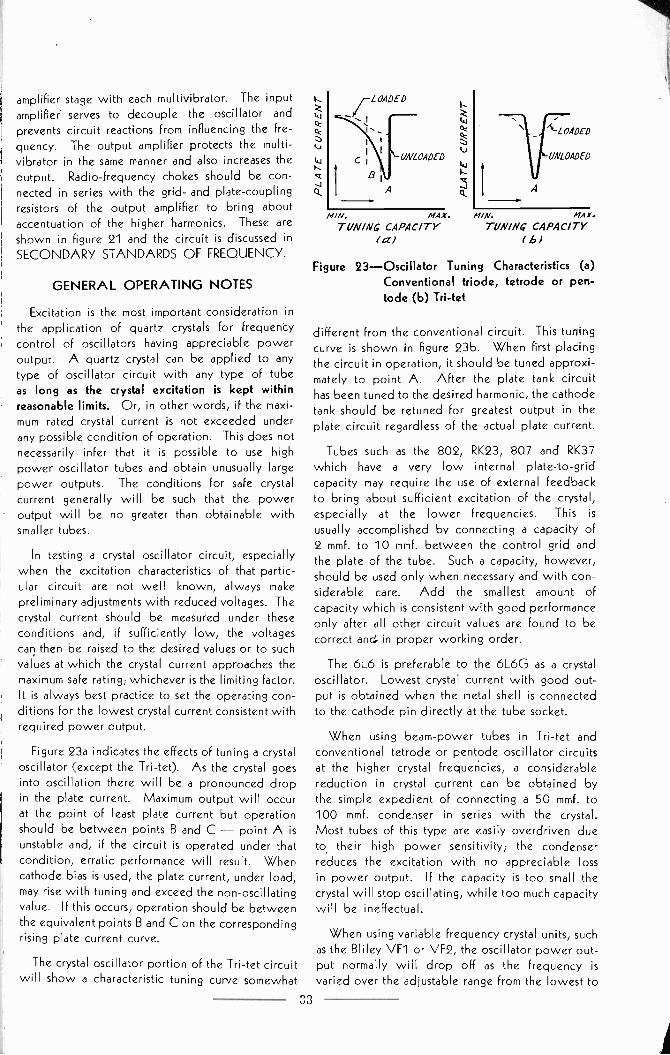
amplifier stage with each multivibrator. The inputamplifier serves to decouple the oscillator and
prevents circuit reactions from influencing the fre-quency. The output amplifier protects the multi -vibrator in the same manner and also increases theoutput. Radio -frequency chokes should be con-nected in series with the grid- and plate -couplingresistors of the output amplifier to bring aboutaccentuation of the higher harmonics. These areshown in figure 21 and the circuit is discussed inSECONDARY STANDARDS OF FREQUENCY.
GENERAL OPERATING NOTES
Excitation is the most important consideration inthe application of quartz crystals for frequencycontrol of oscillators having appreciable poweroutput. A quartz crystal can be applied to anytype of oscillator circuit with any type of tubeas long as the crystal excitation is kept withinreasonable limits. Or, in other words, if the maxi-mum rated crystal current is not exceeded underany possible condition of operation. This does notnecessarily infer that it is possible to use highpower oscillator tubes and obtain unusually largepower outputs. The conditions for safe crystalcurrent generally will be such that the poweroutput will be no greater than obtainable withsmaller tubes.
In testing a crystal oscillator circuit, especiallywhen the excitation characteristics of that partic-ular circuit are not well known, always makepreliminary adjustments with reduced voltages. Thecrystal current should be measured under theseconditions and, if sufficiently low, the voltagescan then be raised to the desired values or to suchvalues at which the crystal current approaches themaximum safe rating; whichever is the limiting factor.It is always best practice to set the operating con-ditions for the lowest crystal current consistent withrequired power output.
Figure 23a indicates the effects of tuning a crystaloscillator (except the Tri-tet). As the crystal goesinto oscillation there will be a pronounced dropin the plate current. Maximum output will occurat the point of least plate current but operationshould be between points B and C - point A isunstable and, if the circuit is operated under thatcondition, erratic performance will result. Whencathode bias is used, the plate current, under load,may rise with tuning and exceed the non -oscillatingvalue. If this occurs, operation should be betweenthe equivalent points B and C on the correspondingrising plate current curve.
The crystal oscillator portion of the Tri-tet circuitwill show a characteristic tuning curve somewhat
LOADED
UNLOADED
A
11/N. MAX.
TUNING CAPACITY(a)
11/N. MAX.
TUN/NC CAPACITYb)
Figure 23-Oscillator Tuning Characteristics (a)Conventional triode, tetrode or pen-tode (b) Tri-tet
different from the conventional circuit. This tuningcurve is shown in figure 23b. When first placingthe circuit in operation, it should be tuned approxi-mately to point A. After the plate tank circuithas been tuned to the desired harmonic, the cathodetank should be retuned for greatest output in theplate circuit regardless of the actual plate current.
Tubes such as the 802, RK23, 807 and RK37which have a very low internal plate -to -gridcapacity may require the use of external feedbackto bring about sufficient excitation of the crystal,especially at the lower frequencies. This is
usually accomplished by connecting a capacity of2 mmf. to 10 mmf. between the control grid andthe plate of the tube. Such a capacity, however,should be used only when necessary and with con-siderable care. Add the smallest amount ofcapacity which is consistent with good performanceonly after all other circuit values are found to becorrect and. in proper working order.
The 6L6 is preferable to the 6L6G as a crystaloscillator. Lowest crystal current with good out-put is obtained when the metal shell is connectedto the cathode pin directly at the tube socket.
When using beam -power tubes in Tri-tet andconventional tetrode or pentode oscillator circuitsat the higher crystal frequencies, a considerablereduction in crystal current can be obtained bythe simple expedient of connecting a 50 mmf. to100 mmf. condenser in series with the crystal.Most tubes of this type are easily overdriven dueto their high power sensitivity; the condenserreduces the excitation with no appreciable lossin power output. If the capacity is too small thecrystal will stop oscillating, while too much capacitywill be ineffectual.
When using variable frequency crystal units, suchas the Bliley VF1 or VF2, the oscillator power out-put normally will drop off as the frequency is
varied over the adjustable range from the lowest to
33

the highest values. The actual amount of poweroutput variation which can be encountered may beas high as 25% in some circuit arrangements. In
conventional triode, tetrode or pentode oscillators,the power output can be made to approach aconstant value by the use of a relatively high Ctank. With the Pierce oscillator -multiplier arrange-ment (figure 11), power output constancy can beimproved through grid -to -cathode feedback as
pointed out in the discussion of that circuit.
Harmonic generating power oscillators usuallymake use of a pentode (or tetrode) tube as a com-bination triode crystal oscillator and pentode fre-quency multiplier. It should be remembered thatthe development of harmonics in such circuits is
basically dependent on the choice of circuit con-ditions to bring about a distorted output. Onlyin instances where the crystal has a very lowactivity does the crystal affect the harmonic genera-tion. The most foolproof harmonic generator is alow -power crystal oscillator driving a beam -powertube. A simple low -voltage oscillator, using a
tube such as the 6C5, 6J5G or 6F6, driving a6L6, 807, RK39 or RK49 frequency multiplier is anexcellent combination.
It has been pointed out that the frequency of anoscillating quartz crystal can be altered by changingits effective equivalent electrical network throughapplication of external reactance. This fact is oftenuseful in instances where it is advisable to slightlychange the frequency of a 'fixed' frequency crystalunit. In triode, tetrode or pentode oscillators ofthe tuned -plate crystal -grid type, the circuit fre-quency can be lowered by connecting capacitydirectly in parallel with the crystal. It is desirablethat an air -condenser be used and it should,naturally, be variable. The maximum amount ofpossible frequency lowering varies with frequency,type of holder and circuit characteristics; it amountsto about 200 cycles/second at 800kc., 1500 cycles/second at 4000kc., 800 cycles/second at 6500kc.and 250 cycles/second at 10,000kc. The effectof the added capacity, is to lower the effectivecrystal activity as the capacity is increased. In anyevent, 75 mmf. represents the maximum usable ca-pacity at any crystal frequency; at high frequencies25 mmf. is maximum.
When a variable air -gap holder is used in
services such as broadcast where very close fre-quency adjustment is necessary, it is sometimes
advantageous to connect a very small variable air -condenser across the crystal. The air -gap adjust-ment then serves as a coarse frequency adjustmentwhereas the condenser acts as a trimmer for finalfrequency setting.
In Pierce oscillators, frequency variation is bestobtained by connecting reactance directly in serieswith the crystal. The use of capacity will raise thefrequency while inductance has the opposite effect.Also, changing the value of the grid -cathode feed-back capacity will influence the frequency. Acapacity in parallel with the crystal likewise willcause a frequency change due to the fact that thecrystal does not work purely at its natural resonantfrequency; the use of such capacity, however, veryrapidly decreases the effective crystal activity.
Occasionally, kinks will be found in variousradio periodicals to the effect that the frequency ofa crystal can be lowered by coating its faces withIndia ink, iodine or some other material. Theeffectiveness of such a process is dependent uponthe fact that the coating dampens the crystal andincreases its effective mass; the result is a loweringof frequency. Oppositely, the frequency can beraised by inserting a piece of paper between thecrystal and one of its electrodes to, in effect, createan air -gap. In either case, the total amount ofpossible frequency change is quite limited and isaccompanied by a rapid decrease in activity. If thecrystal is subjected to relatively high excitation,arcing might occur finally causing fracturing as aresult of the concentrated heat of the arc. Also,with some crystals, erratic performance and encour-agement of a frequency jump can occur. Simple
reasoning dictates that altering crystal frequency byphysical means as described should be applied onlyas an emergency measure where a special situationdemands such action.
As explained in previous sections, excessive
excitation will fracture a quartz crystal renderingit useless. The following are the outstandingsources of excessive excitation: (1) high tubevoltages, (2) too much bias; grid -leak, cathode orcombinations of both, (3) insufficient by-passingof the screen -grid circuit, (4) stray oscillator plate -to -grid feedback brought about by improper circuitlayout, (5) the existence of strong parasitics in theoscillator, (6) operating straight through on thecrystal frequency in the Tri-tet circuit with poorinternally shielded tubes such as the 59, 47, 42,6L6, 6F6, (7) improper interstage shielding bring-ing about undesirable coupling between the oscil-lator and some other stage of the transmitter, (8)feedback into the oscillator stage brought aboutby self -oscillation in one of the buffer stages or thefinal amplifier, (9) improper circuit vaues withoscillators in which the crystal feedback is con-
siderably dependent on circuit adjustments, (10)failing to place the band switch in its properposition with the Bi-Push Exciter, or, (11) in certaininstances, by removing the plate voltage from a
34
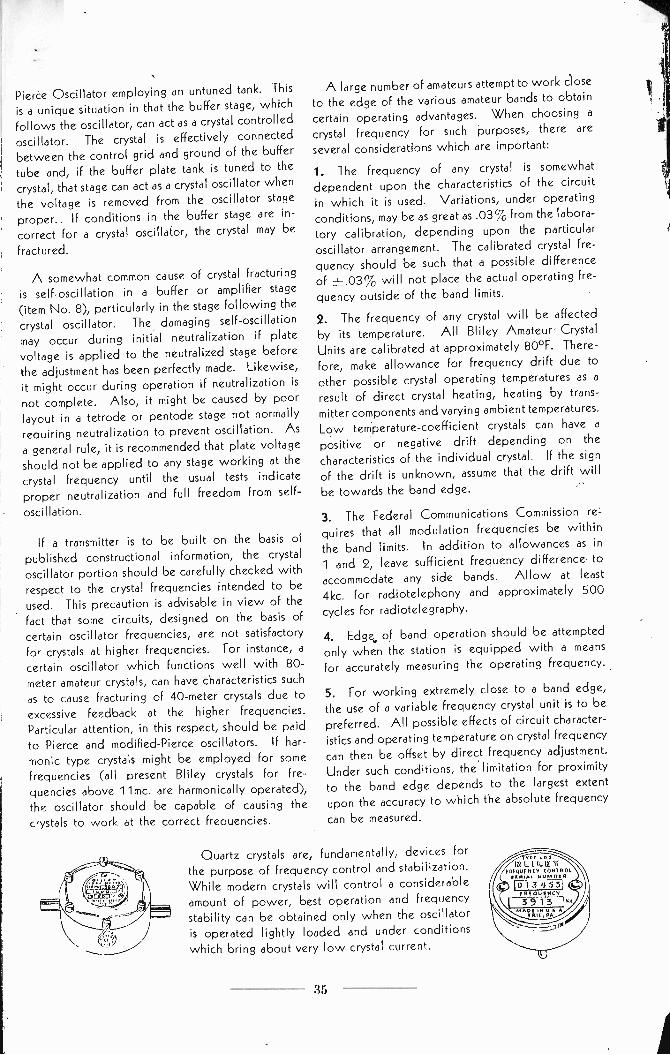
Pierce Oscillator employing an untuned tank. This
is a unique situation in that the buffer stage, whichfollows the oscillator, can act as a crystal controlled
oscillator. The crystal is effectively connected
between the control grid and ground of the buffer
tube and, if the buffer plate tank is tuned to thecrystal, that stage can act as a crystal oscillator when
the voltage is removed from the oscillator stage
proper.. If conditions in the buffer stage are in-
correct for a crystal oscillator, the crystal may be
fractured.
A somewhat common cause of crystal fracturing
is self -oscillation in a buffer or amplifier stage(item No. 8), particularly in the stage following the
crystal oscillator. The damaging self -oscillation
may occur during initial neutralization if plate
voltage is applied to the neutralized stage before
the adjustment has been perfectly made. Likewise,
it might occur during operation if neutralization is
not complete. Also, it might be caused by poorlayout in a tetrode or pentode stage not normally
requiring neutralization to prevent oscillation. As
a general rule, it is recommended that plate voltage
should not be applied to any stage working at the
crystal frequency until the usual tests indicate
proper neutralization and full freedom from self -
oscillation.
If a transmitter is to be built on the basis ofpublished constructional information, the crystaloscillator portion should be carefully checked withrespect to the crystal frequencies intended to be
used. This precaution is advisable in view of thefact that some circuits, designed on the basis of
certain oscillator frequencies, are not satisfactory
for crystals at higher frequencies. For instance, a
certain oscillator which functions well with 80 -meter amateur crystals, can have characteristics such
as to cause fracturing of 40 -meter crystals due to
excessive feedback at the higher frequencies.Particular attention, in this respect, should be paidto Pierce and modified -Pierce oscillators. If har-monic type crystals might be employed for somefrequencies (all present Bliley crystals for fre-
quencies above 11mc. are harmonically operated),the oscillator should be capable of causing thecrystals to work at the correct frequencies.
A large number of amateurs attempt to work close
to the edge of the various amateur bands to obtain
certain operating advantages. When choosing a
crystal frequency for such purposes, there are
several considerations which are important:
1. The frequency of any crystal is somewhat
dependent upon the characteristics of the circuit
in which it is used. Variations, under operatingconditions, may be as great as .03% from the labora-
tory calibration, depending upon the particular
oscillator arrangement. The calibrated crystal fre-
quency should be such that a possible differenceof ±.03% will not place the actual operating fre-
quency outside of the band limits.
2. The frequency of any crystal will be affected
by its temperature. All Bliley Amateur' CrystalUnits are calibrated at approximately 80°F. There-
fore, make allowance for frequency drift due toother possible crystal operating temperatures as aresult of direct crystal heating, heating by trans-
mitter components and varying ambient temperatures.
Low temperature -coefficient crystals can have a
positive or negative drift depending on the
characteristics of the individual crystal. If the sign
of the drift is unknown, assume that the drift willbe towards the band edge.
3. The Federal Communications Commission re-
quires that all modulation frequencies be within
the band limits. In addition to allowances as in1 and 2, leave sufficient frequency difference toaccommodate any side bands. Allow at least
4kc. for radiotelephony and approximately 500
cycles for radiotelegraphy.
4. Edge, of band operation should be attempted
only when the station is equipped with a meansfor accurately measuring the operating frequency.
5. For working extremely close to a band edge,
the use of a variable frequency crystal unit is to be
preferred. All possible effects of circuit character-
istics and operating temperature on crystal frequency
can then be offset by direct frequency adjustment.
Under such conditions, the limitation for proximity
to the band edge depends to the largest extent
upon the accuracy to which the absolute frequency
can be measured.
Quartz crystals are, fundamentally, devices for
the purpose of frequency control and stabilization.
While modern crystals will control a considerable
amount of power, best operation and frequency
stability can be obtained only when the oscillatoris operated lightly loaded and under conditions
which bring about very low crystal current.
LotILLDLIET
PROUENCY CONTROL1111111.41.
0 I 3 .4 5 5
vvr,4"
35

In answer to your question, we would suggest that you use a
2 volt .06 ampere lamp in series with the crystal as a pro-
tective device.
In order to keep stray circuit capacities
to a minimum, it is essential that the lamp leads be soldered
directly to the lamp base and be made as short and direct
as possible.
Such a lamp properly installed will insure reason-
able protection against excessive crystal current.
It is, however, quite possible for a sudden surge of current
to fracture the crystal without damaging the lamp in any way.
For a complete discussion of this subject, it is suggested that
you
obtain a copy of our Engineering Bulletin entitled, "Fre-
quency
Control With Quartz Crystals."
This bulletin may be se-
cured from any Bliley distributor or direct from our factory at
the regular charge of 100.
We appreciate the opportunity of furnishing the type HF2 crystal,
and hope that our service will meet with your approval.
Very truly yours,
W. S. Riblet,
Sales Department.
ASR:GC

EL
IC C
OM
PA
NY
Manufacturers of Q
UA
RT
Z
UN
ION
ST
AT
ION
BU
ILDIN
G, E
RIE
,P
EN
NS
YLV
AN
IA
June 22, 1939.
Mr. Bertram Aaron,
6811 Huntington Avenue,
Newport News, Virginia.
Dear Sir:
This will acknowledge and thankyou for your remittance of
$5.75 and your letter of June 15, specifying one HF2 10 -
meter crystal unit at approximately 29.25mc.
Your order
has been released for production and shipment of the crystal
went forward to you on June 20 under our packing slip No.
'9'1441')

In answer toyour question, we would suggest that you use a
2 volt .06 ampere lamp in series with the
crystal as a pro-
tective device.
In order to keep stray circuit
capacities
to a minimum, it is essential that the
lamp leads be soldered
directly to the lamp base and be made as short and direct
as possible.
Such a lamp properly installed will
insure reason-
able protection against excessive
crystal current.
It is, however, quite possible for a sudden
surge of current
to fracture the crystal without damaging the lamp in
any way.
For a complete discussion of this subject, it is
suggested that
you obtain a copy of our Engineering Bulletin entitled, "Fre-
quency Control With Quartz Crystals."
This bulletin
may be se-
cured from any Bliley distributor or direct from
our factory at
the regular charge of 1.00.
We appreciate the opportunity of furnishing the
type HF2 crystal,
and hope that our service will meet withyour approval.
Very truly yours,
W. S. Riblet,
Sales Department.
WSR:GC

EL
IC C
OM
PA
NY
Manufacturers of Q
UA
RT
Z
UN
ION
ST
AT
ION
BU
ILDIN
G,
ER
IE, P
EN
NS
YLV
AN
IA
June 22, 1939.
Mr. Bertram Aaron,
6811 Huntington
Avenue,
Newport News, Virginia.
Dear Sir:
This will acknowledge and
thankyou for your remittance of
$5.75 andyour letter of June 15, specifying one HF2 10-
meter crystal unit at
approximately 29.25mc.
Your order
has been released forproduction and shipment of the
crystal
went forward to
you on June 20 under our, packing slip No.
110-vp
COPYRIGHT 1940 BLILEY ELECTRIC CO.
ERIE, PA.
ENGINEERING BULLETIN E-6
PRINTED IN U.