Embed Size (px)
Citation preview
QUARTERLY RESEARCH REPORT(REPORTING PERIOD 01/01/97-03/31/97)
ON
SLAG CHARACTERIZATION AND REMOVAL USING PULSE DETONATIONTECHNOLOGY DURING COAL GASIFICATION
PROGRAM IDENTIFICATION NUMBER: DE-FG22-95MT95010
SUBMITTED TO:
DOCUMENT CONTROL CENTERU S DEPARTMENT OF ENERGY
PITTSBURGH ENERGY TECHNOLOGY CENTERP O BOX 10940 MS 921-143
PITTSBURGH PA 15236-0940
SUBMITTED BY: DR. ZIAUL HUQUE, DR. DANIEL MEI, DR. PAUL O. BINEY, DR.JIANREN ZHOU
DEPARTMENT OF MECHANICAL ENGINEERINGPRAIRIE VIEW A&M UNIVERSITY
P O BOX 397PRAIRIE VIEW TX 77446
TEL: (409)-857-4023 FAX: (409)-857-4395
MARCH 25, 1997
1
DISCLAIMER
This report was prepared as an account of work sponsored by an agency of the United SatesGovernment. Neither the United States Government nor any agency thereof, nor any of theiremployees, makes any warranty, express or implied, or assurance any legal liability orresponsibility for the accuracy, completeness, or usefulness of any information, apparatus,product, or process disclosed, or represents that its use would not infringe privately owned rights.Reference herein to any specific commercial product, process, or service by trade name,trademark, manufacturer, or otherwise does not necessarily constitute or imply its endorsement,recommendation, or favoring by the United States Government or any agency thereof. The viewsand opinions of authors expressed herein do not necessarily state or reflect those of the UnitedStates Government or any agency thereof.
ABSTRACT
This quarterly report has been written based on the research activities performed during theperiod 01/01/97 through 03/31/97. One paper Titled “Application of Detonation Wave forRemoving Economizer Slag in Coal-Fired Utility Boilers” was presented in the College ofEngineering and Architecture Symposium, Prairie View A&M University. A performance reportwas written based on the achievements during last year and presented at Energy Research andDevelopment Technology Transfer Symposium, Historically Black Colleges and Universities(HBCU) Contractors Review Meeting, Baton Rouge, Louisiana (March 3, 1997).
TABLE OF CONTENTS
Disclaimer …………………………………………………………………………1
Abstract …………………………………………………………………………1
Executive Summary ………………………………………………………………………….2
Paper:“Application of Detonation Wave for RemovingEconomizer Slag in Coal-Fired Utility Boilers” ………………………………….3
Progress report: “Slag Characterization and Removal Using PulseDetonation Technology for Coal Gasification” …………………………10
2
EXECUTIVE SUMMARY
A paper Titled “Application of Detonation Wave for Removing Economizer Slag in Coal-FiredUtility Boilers” was presented in E&A ’97 symposium, College of Engineering and Architecture,Prairie View A&M University, TX , February 05, 1997. The paper is attached.
A progress report was written based on the achievements during last one year and presented atEnergy Research and Development Technology Transfer Symposium, Historically Black Collegesand Universities (HBCU) Contractors Review Meeting, Baton Rouge, Louisiana (March 3,1997). The abstract of the report is attached.
As reported in the previous quarterly reports, the test were performed with slags on tubes in axialpositions. The test results showed that the detonation wave is capable of chipping off the slagfrom the tube if no other tube is in the front position. The results also showed that the detonationwave is less effective in removing slag from the back side of tube. But Computational FluidDynamic (CFD) study showed that the detonation wave is effective in removing the slag fromboth sides of tubes if they are arranged in a bundle. In the bundle, wave reflection andreverberation occurs which has the additional effects to remove the slag . In order to study theeffects of wave reflection and reverberation, tests are planed to be performed with tube bundles.A multi-tube position fixture with tube arranged in a bundle was designed and fabricated.
The multi shot testing will be performed in the middle of July. We are in contact with theAerospace Research Center at University of Texas, Arlington to use their Pulse DetonationEngine to perform the test.
We are in process to get more information about the feasibility study report submitted lastquarterly. Dr. Louis Hunter of Lockheed Martin Co. provided the report and we are in contactwith him. Once we get the information, we will write a report and send it to the document controlcenter.
3
Application of Detonation Wave for RemovingEconomizer Slag in Coal-Fired Utility Boilers
Muhammad R. Ali, Ziaul HuqueDepartment of Mechanical Engineering
Prairie View A&M UniversityP.O.Box 397
Prairie View, TX 77446Phone: (409)-857-4023 Fax: (409)-857-4395
e-mail: [email protected]
ABSTRACT
Boiler slagging and fouling as a result of inorganic impurities in combustion gases being depositedon heat transfer tubes have caused severe problems in coal-fired power plant operation. Theseproblems are fuel, system design, and operating condition dependent. Pulse detonation technologyfor the purpose of removing slag and fouling deposits in coal-fired utility power plant boilersoffers great potential. The detonation wave technique based on high impact velocity withsufficient energy and thermal shock on the slag deposited on gas contact surfaces offers aconvenient, inexpensive, yet efficient and effective way to supplement existing slag removalmethods. These detonation waves have been demonstrated experimentally to have exceptionallyhigh shearing capability important to the task of removing slag and fouling deposits. Theexperimental results show that the single shot detonation wave is capable of removing the entireslag ( types of slag deposited on economizer) even at a distance of 8 in. from the exit of adetonation engine tube. Wave strength and slag orientation also have different effects on thechipping off of the slag. This paper discusses about the results obtained in effectively removingthe economizer slag.
INTRODUCTION
Historically, boiler slagging and fouling as a result of inorganic impurities in combustion gasesbeing deposited on heat transfer tubes have caused severe problems in coal-fired power plantoperation. These problems are fuel, system design, and operating condition dependent.Conventional ash removal methods include the use of in situ blowing or jet-type devices such asair or steam soot blowers and water lances. In soot blower and water lance cleaning devices beingonly partially successful in removing deposits, they also require considerable maintenance, andthey reduce boiler efficiency when in use. Alternative technologies are therefore needed to more
4
efficiently and effectively remove ash deposits from heat transfer surfaces of utility boilers duringfull power plant operation. New methods are specially needed to remove deposits from thedownstream side of heat transfer tube bundles in the convective pass sections. Pulse detonationwaves offer potential solutions to many of the slag deposit problems by providing simple,inexpensive, yet efficient and effective ways to supplement existing ash removal methods, withoutexpensive plant shut down. The three main areas in which work has been performed during thepast one year are in slag characterization studies, pulse detonation technology studies, and singlepulse testing on slag removal. Considerable achievement have been accomplished in each of thethree areas during the past year.
SLAG CHARACTERIZATION
The slag characterization studies were performed by MTI and provided to Prairie View A&MUniversity (PVAMU). MTI provided background information on fuel properties, ash deposition,ash formation, and ash removal based on Coal Analysis, Deposit Analysis, and Deposit Phase andCompositional Analysis. Deposit Analysis includes Deposit descriptions, Morphological Analysisand Porosity Calculations, and Scanning Electron Microscopy of polished cross-section ofsample. In addition, MTI provided slags from basin electric deposits and northern states powerdeposits for testing. The basin electric deposits have a medium-to-low porosity, low crystallinity,and are sulfate based. The sulfation process fills pores and increase density. This set of depositsrepresent a wide range of deposits found in the convective pass of a utility boiler firing a highcalcium subbituminous coal. These subbituminous coals are being used extensively in the U.S. forpower generation. The northern states power deposits were characterized to determine some ofthe chemical and physical properties that effect the strength of the deposit as well as the resistanceto removal. The deposits range in porosity (area percent epoxy) from 44.4% for the weakest to29.4% for the strongest. The lower critical porosity value for slag removal from full scale utilityboilers by a soot blower is about 25% porosity. The deposits are primarily sulfate based withvarying levels of sulfation. The microstructure indicated coating on the particles that are likelycontributing to the strength development. These chemical and physical properties of the depositsinfluence the ability of conventional soot blowers to remove the deposits.
SLAG FORMATION AND REMOVAL
During combustion or gasification the inorganic materials are transformed into ash species that arein the form of gases, liquids and solids. The submicron size of particles form as a result ofcondensation of flame volatalized species upon gas cooling. Flame volatalized species may alsocondense on the surface of larger particles or deposits. The larger particles are sometimes referredto as residual ash, which is largely derived from mineral grains. Ash deposit formation is related tocoal quality ( chemical and physical characteristics of the inorganic material ), system operatingconditions, and system design and consists of both slag deposits and fouling deposits. Slagdeposits are those that form in the radiant section of the boiler. Fouling deposits are characteristicof those found in the convective pass of the boiler. The chemical and physical characteristics ofutility boiler deposits vary widely. Slag deposits typically contain more liquid phase components
5
causing more assimilation and reaction of the ash particles. Fouling deposits consists of twoprimary types, i.e., high temperature silicate deposits and low temperature sulfate-based deposits.These deposits types form under very different temperatures and form very different ash materials.At low temperatures, sulfates dominate, while at higher temperatures, silicates are more prone tocause deposits. In high-temperature fouling, the bonding of particles is due to silicate liquidphases and in low-temperature fouling, the bonding is a result of formation of sulfates. Condensedsulfur species, principally in the form of CaSo4 are stable and form the matrix or bonding materialin the low-temperature deposits. High temperature fouling occurs in regions of the utility boilerwhere temperatures exceed the stability of the sulfate-bearing phases Deposits in the convectivepass of utility boilers collect on both upstream and downstream side of tubes. The particlescollected on the downstream side of the tube area are a result of small particles that are caught inthe circulation eddies and impinge upon the downstream side of the tubes.
The primary factors that influence the ability to be removed are the strength of the deposit and theadhesive bond between the ash deposit and the heat transfer surface. The removal of the depositinvolves breaking the deposit matrix and/or breaking the bond between the deposit and heattransfer surface. Methods typically used to remove deposits include load reduction and on-linecleaning. Load reduction results in cooling of the deposit and heat transfer surface because of adifferential in the thermal expansion coefficients between the deposit and heat transfer surface.On-line ash deposit cleaning devices are called sootblowers. The blowing medium is either highpressure steam or compressed air. The blowing medium is directed at the deposit through anozzle. The impacting fluid causes the deposit to crack and eroded away. The design of theblowers vary depending upon the location in the boiler. For extremely difficult to remove depositswater-jet sootblowers have been used. These work well to remove large accumulations ofdeposits in the furnace. The impact of water is much greater than that of air or steam so it iseffective in removing deposits. Unfortunately, removing deposits formed on the downstream sideof the tube is not possible using conventional sootblowing techniques.
PULSE DETONATION TECHNOLOGY
Pulse detonation technology studies were performed by both PVAMU and Lockheed Martin Co.under subcontract from PVAMU. Pulse detonation technology for the purpose of removingfouling ash deposits in heat exchangers was evaluated by running Lockheed supplied an algebricPulse simulation CFD code using 2-D time dependent methods to determine the effect of adetonation wave passing through a 3-tube heat exchanger. Pressure, pressure gradients,temperature and velocities were recorded as a function of time. Wave reverberations were notedon the back side of the heat exchanger lead tube. Conventional methods clean the front side of thetubes, but have great difficulty on the back side. The CFD results show a thorough scrubbing ofthe cylinders on all sides. The CFD results also showed that the number more tubes infront ofdetonation waves the better are the result in terms of reverberation activity. The study alsoshowed large negative velocities impinging on the back side of the lead tube as a result of fixturesbeing placed over and under the tube bank and the wave interaction between the tubes. Thesesingle shot detonation wave studies indicate peak pressures of several hundred atmospheres which
6
act over a very short period of time and which fall of very rapidly. Pressure gradients movearound the tubes and large velocities alternate with pressure which scrub all surfacescircumferentially to remove the ash. Wave strength is an important variable for slag depositremoval applications. A full strength detonation wave is referred to as a Chapman-Jouget (C-J)wave. Its velocity is approximately 2200 meters per second and its maximum pressure jumpapproximately 20 times that of unburned reactants.
SINGLE PULSE TESTING
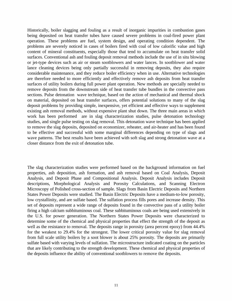
Test chamber facilityA pulse detonation facility specially designed to study detonation waves at the University of Texasat Arlington has been utilized to remove slags using single shot detonation waves. The maincomponents of the pulse detonation facility are the test chamber, the injection system, the ignitionsystem and the instrumentation. To hold the slag samples at the exit of detonation tube, twodifferent types of fixture (mounting) was designed and fabricated at Prairie View A&MUniversity. The injection system was upgraded for repetitive use. A control circuit was alsodesigned and built to sense the injection of fuel and oxidizer, provide a short time delay, fire theignition source, recharge the ignition capacitor bank and provide a synchronized signal to the dataacquisition system if required or desired. The overall schematic of UTA detonation engineincluding the fixture is given in Figure 1.
Test ChamberThe test chamber consists of steel tubes of varying length connected end to end in differentcombinations but with the same cross sectional area. The three different segment lengths are 7.62cm (3 in.) , 15.24 cm (6 in.) and 30.48 cm (12 in.). Each section has an inner diameter of 7.62 cm(3 in.) and an outer diameter of 13.97 cm (5.5 in.). A 1.905 cm (0.75 in.) thick flange is welded toeach end of the test sections. Each section of the chamber has provisions for mounting pressuretransducers, thermocouples, thin film gauges and heat flux gauges every 7.62 cm (3 in.). Theignition plug is mounted in a 7.62 cm (3 in.) section and can be inserted any where along thelength of the tube between other sections. One end of the chamber is sealed with a plate. The fueland oxidizer is injected through this plate. The various sections of the chamber are flanged andbolted together at each joint. The open end of the chamber is bolted to a thrust stand to hold thechamber in place.
Injection SystemThe fuels and oxidizers are injected through an passage on the end plate which closes one end ofthe tube. The opposite end is open for the exhaust of the detonation wave and combustionproduct. The rotary injection valves are connected together by pulleys and timing belt, turned by avariable speed electric motor, controlled remotely from the control room for frequency control. Amagnetic pickup is located nearby to sense the closure of the valves and initiate the ignitionprocess.
7
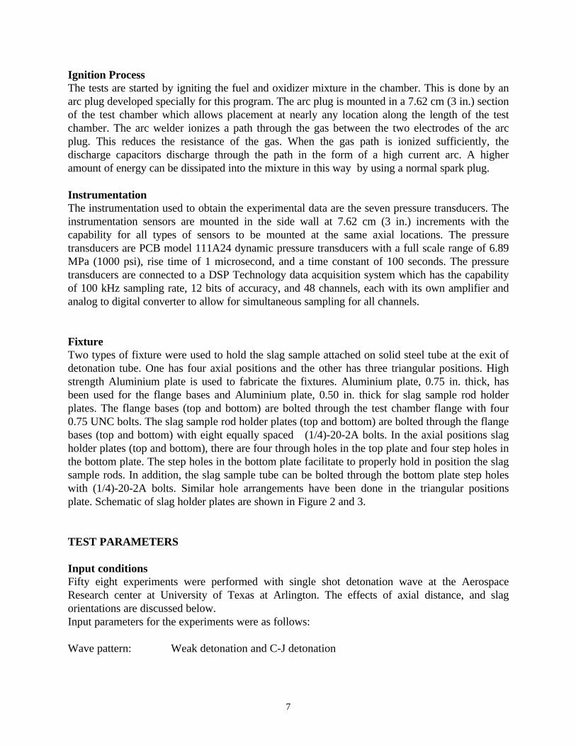
Ignition ProcessThe tests are started by igniting the fuel and oxidizer mixture in the chamber. This is done by anarc plug developed specially for this program. The arc plug is mounted in a 7.62 cm (3 in.) sectionof the test chamber which allows placement at nearly any location along the length of the testchamber. The arc welder ionizes a path through the gas between the two electrodes of the arcplug. This reduces the resistance of the gas. When the gas path is ionized sufficiently, thedischarge capacitors discharge through the path in the form of a high current arc. A higheramount of energy can be dissipated into the mixture in this way by using a normal spark plug.
InstrumentationThe instrumentation used to obtain the experimental data are the seven pressure transducers. Theinstrumentation sensors are mounted in the side wall at 7.62 cm (3 in.) increments with thecapability for all types of sensors to be mounted at the same axial locations. The pressuretransducers are PCB model 111A24 dynamic pressure transducers with a full scale range of 6.89MPa (1000 psi), rise time of 1 microsecond, and a time constant of 100 seconds. The pressuretransducers are connected to a DSP Technology data acquisition system which has the capabilityof 100 kHz sampling rate, 12 bits of accuracy, and 48 channels, each with its own amplifier andanalog to digital converter to allow for simultaneous sampling for all channels.
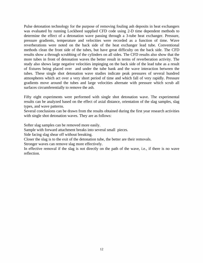
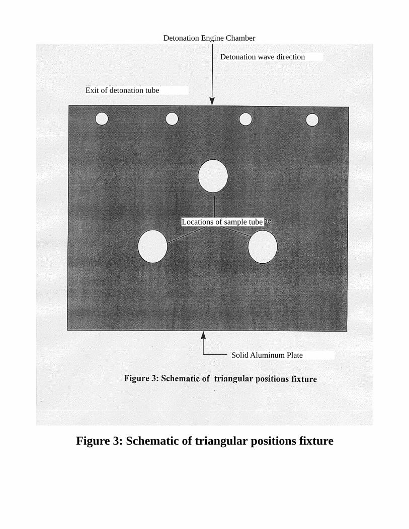
FixtureTwo types of fixture were used to hold the slag sample attached on solid steel tube at the exit ofdetonation tube. One has four axial positions and the other has three triangular positions. Highstrength Aluminium plate is used to fabricate the fixtures. Aluminium plate, 0.75 in. thick, hasbeen used for the flange bases and Aluminium plate, 0.50 in. thick for slag sample rod holderplates. The flange bases (top and bottom) are bolted through the test chamber flange with four0.75 UNC bolts. The slag sample rod holder plates (top and bottom) are bolted through the flangebases (top and bottom) with eight equally spaced (1/4)-20-2A bolts. In the axial positions slagholder plates (top and bottom), there are four through holes in the top plate and four step holes inthe bottom plate. The step holes in the bottom plate facilitate to properly hold in position the slagsample rods. In addition, the slag sample tube can be bolted through the bottom plate step holeswith (1/4)-20-2A bolts. Similar hole arrangements have been done in the triangular positionsplate. Schematic of slag holder plates are shown in Figure 2 and 3.
TEST PARAMETERS
Input conditionsFifty eight experiments were performed with single shot detonation wave at the AerospaceResearch center at University of Texas at Arlington. The effects of axial distance, and slagorientations are discussed below.Input parameters for the experiments were as follows:
Wave pattern: Weak detonation and C-J detonation
8
Types of slag: MTI 96-54, MTI 96-55, MTI 96-56
Types of fixture: (a) 4 axial positions (b) 1 triangular configuration
Slag orientation: Front, back and side mounting.
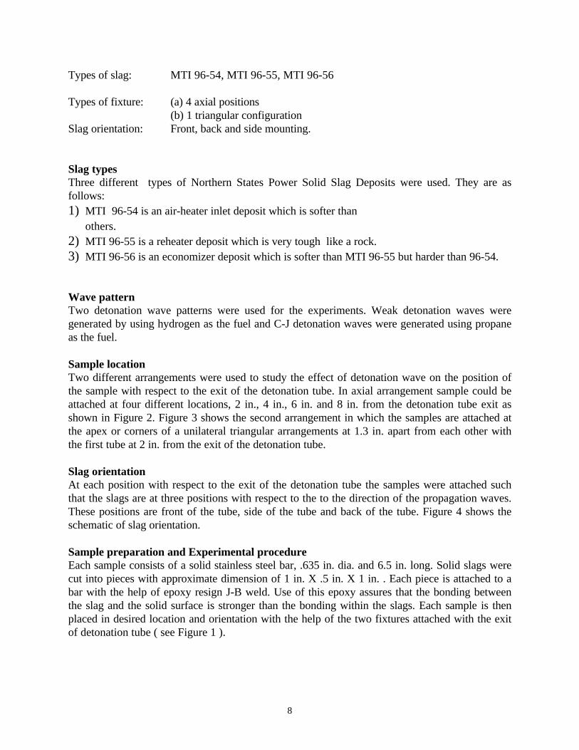
Slag typesThree different types of Northern States Power Solid Slag Deposits were used. They are asfollows:1) MTI 96-54 is an air-heater inlet deposit which is softer than others.2) MTI 96-55 is a reheater deposit which is very tough like a rock.3) MTI 96-56 is an economizer deposit which is softer than MTI 96-55 but harder than 96-54.
Wave patternTwo detonation wave patterns were used for the experiments. Weak detonation waves weregenerated by using hydrogen as the fuel and C-J detonation waves were generated using propaneas the fuel.
Sample locationTwo different arrangements were used to study the effect of detonation wave on the position ofthe sample with respect to the exit of the detonation tube. In axial arrangement sample could beattached at four different locations, 2 in., 4 in., 6 in. and 8 in. from the detonation tube exit asshown in Figure 2. Figure 3 shows the second arrangement in which the samples are attached atthe apex or corners of a unilateral triangular arrangements at 1.3 in. apart from each other withthe first tube at 2 in. from the exit of the detonation tube.
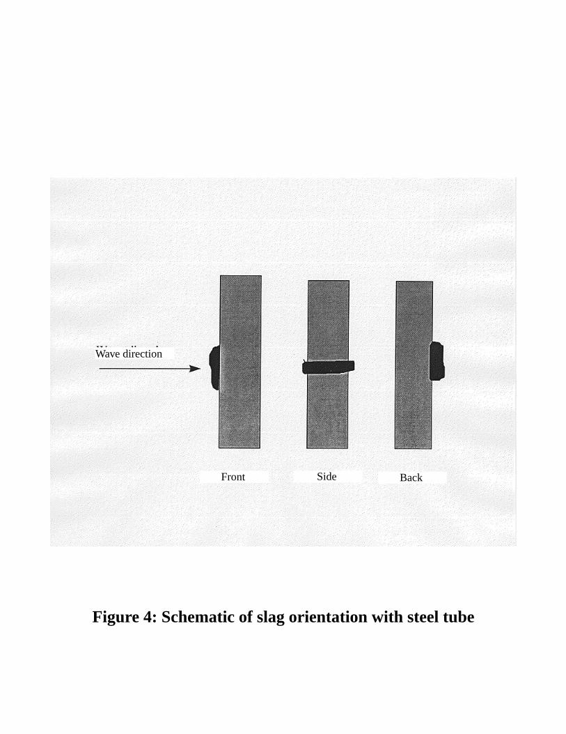
Slag orientationAt each position with respect to the exit of the detonation tube the samples were attached suchthat the slags are at three positions with respect to the to the direction of the propagation waves.These positions are front of the tube, side of the tube and back of the tube. Figure 4 shows theschematic of slag orientation.
Sample preparation and Experimental procedureEach sample consists of a solid stainless steel bar, .635 in. dia. and 6.5 in. long. Solid slags werecut into pieces with approximate dimension of 1 in. X .5 in. X 1 in. . Each piece is attached to abar with the help of epoxy resign J-B weld. Use of this epoxy assures that the bonding betweenthe slag and the solid surface is stronger than the bonding within the slags. Each sample is thenplaced in desired location and orientation with the help of the two fixtures attached with the exitof detonation tube ( see Figure 1 ).
9
RESULTS AND DISCUSSION
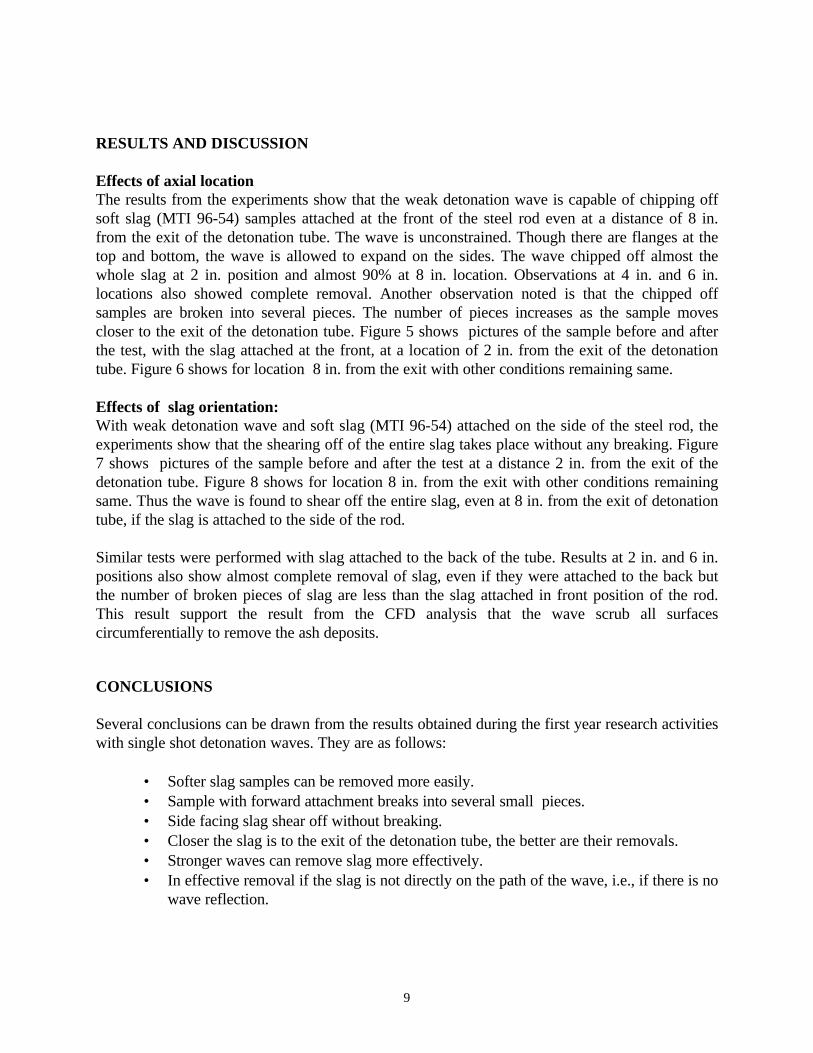
Effects of axial locationThe results from the experiments show that the weak detonation wave is capable of chipping offsoft slag (MTI 96-54) samples attached at the front of the steel rod even at a distance of 8 in.from the exit of the detonation tube. The wave is unconstrained. Though there are flanges at thetop and bottom, the wave is allowed to expand on the sides. The wave chipped off almost thewhole slag at 2 in. position and almost 90% at 8 in. location. Observations at 4 in. and 6 in.locations also showed complete removal. Another observation noted is that the chipped offsamples are broken into several pieces. The number of pieces increases as the sample movescloser to the exit of the detonation tube. Figure 5 shows pictures of the sample before and afterthe test, with the slag attached at the front, at a location of 2 in. from the exit of the detonationtube. Figure 6 shows for location 8 in. from the exit with other conditions remaining same.
Effects of slag orientation:With weak detonation wave and soft slag (MTI 96-54) attached on the side of the steel rod, theexperiments show that the shearing off of the entire slag takes place without any breaking. Figure7 shows pictures of the sample before and after the test at a distance 2 in. from the exit of thedetonation tube. Figure 8 shows for location 8 in. from the exit with other conditions remainingsame. Thus the wave is found to shear off the entire slag, even at 8 in. from the exit of detonationtube, if the slag is attached to the side of the rod.
Similar tests were performed with slag attached to the back of the tube. Results at 2 in. and 6 in.positions also show almost complete removal of slag, even if they were attached to the back butthe number of broken pieces of slag are less than the slag attached in front position of the rod.This result support the result from the CFD analysis that the wave scrub all surfacescircumferentially to remove the ash deposits.
CONCLUSIONS
Several conclusions can be drawn from the results obtained during the first year research activitieswith single shot detonation waves. They are as follows:
• Softer slag samples can be removed more easily.• Sample with forward attachment breaks into several small pieces.• Side facing slag shear off without breaking.• Closer the slag is to the exit of the detonation tube, the better are their removals.• Stronger waves can remove slag more effectively.• In effective removal if the slag is not directly on the path of the wave, i.e., if there is no
wave reflection.
10
REFERENCES
Huque, Ziaul and others, 1995, “ Slag Characterization and Removal Using Pulse DetonationTechnology for Coal Gasification”. Technical proposal submitted to PETC.
Steven A. Bension, 1996, “ Slag Characterization Study”. Quarterly Reportsubmitted to PVAMU.
Characterization and Removal of SlagDeposits Using Pulse Detonation Technology for
Coal Gasification
Muhammad R. Ali, Ziaul HuqueDepartment of Mechanical Engineering
Prairie View A&M UniversityP.O.Box 397
Prairie View, TX 77446Phone: (409)-857-4023 Fax: (409)-857-4395
e-mail: [email protected]
ABSTRACT
Pulse detonation technology for the purpose of removing slag and fouling deposits in coal-firedutility power plant boilers offers great potential. The detonation wave technique based on highimpact velocity with sufficient energy and thermal shock on the slag deposited on gas contactsurfaces offers a convenient, inexpensive, yet efficient and effective way to supplement existingslag removal methods. These detonation waves have been demonstrated experimentally to haveexceptionally high shearing capability important to the task of removing slag and fouling deposits.The experimental results prove that the single shot detonation wave technique is efficient andreliable in comparison with various conventional cleaning methods. Wave strength and slagorientation also have different effects on the chipping off of the slag. The three main areas inwhich work has been performed during the past one year are in slag characterization studies, pulsedetonation technology studies, and single pulse testing on slag removal. Considerable achievementhave been accomplished in each of the three cases. This abstract discusses about the resultsobtained in effectively removing the slag with single shot detonation wave up to a distance of 8 in.from the exit of detonation tube.
11
Historically, boiler slagging and fouling as a result of inorganic impurities in combustion gasesbeing deposited on heat transfer tubes have caused severe problems in coal-fired power plantoperation. These problems are fuel, system design, and operating condition dependent. Theproblems are severely noticed in cases of boilers fired with coal of low calorific value and highcontent of mineral constituents, especially those that tend to accumulate on heat transfer solidsurfaces. Conventional ash and fouling deposit removal methods include the use of in situ blowingor jet-type devices such as air or steam sootblowers and water lances. In sootblower and waterlance cleaning devices being only partially successful in removing deposits, they also requireconsiderable maintenance, and they reduce boiler efficiency when in use. Alternative technologiesare therefore needed to more efficiently and effectively remove ash deposits from heat transfersurfaces of utility boilers during full power plant operation. New methods are specially needed toremove deposits from the downstream side of heat transfer tube bundles in the convective passsections. Pulse detonation wave technique, based on the action of mechanical and thermal shockon material, deposited on heat transfer surfaces, offers potential solutions to many of the slagdeposit problems by providing simple, inexpensive, yet efficient and effective ways to supplementexisting ash removal methods, without expensive plant shut down. The three main areas in whichwork has been performed are in slag characterization studies, pulse detonation technologystudies, and single pulse testing on slag removal. This detonation wave technique has been appliedto remove the slag deposits, deposited on economizer, reheater, and air-heater and has been foundto be effective and successful with some marginal differences depending on type of slags andwave patterns. The best results have been achieved with soft slag and strong detonation wave at acloser distance from the exit of detonation tube.
The slag characterization studies were performed based on the background information on fuelproperties, ash deposition, ash formation, and ash removal based on Coal Analysis, DepositAnalysis, and Deposit Phase and Compositional Analysis. Deposit Analysis includes Depositdescriptions, Morphological Analysis and Porosity Calculations, and Scanning ElectronMicroscopy of Polished cross-section of sample. Slags from Basin Electric Deposits and NorthernStates Power Deposits were studied. The Basin Electric Deposits have a medium-to-low porosity,low crystallinity, and are sulfate based. The sulfation process fills pores and increase density. Thisset of deposits represent a wide range of deposits found in the convective pass of a utility boilerfiring a high calcium subbituminous coal. These subbituminous coals are being used extensively inthe U.S. for power generation. The Northern States Power Deposits were characterized todetermine some of the chemical and physical properties that effect the strength of the deposit aswell as the resistance to removal. The deposits range in porosity (area percent epoxy) from 44.4%for the weakest to 29.4% for the strongest. The lower critical porosity value for slag removalfrom full scale utility boilers by a soot blower is about 25% porosity. The deposits are primarilysulfate based with varying levels of sulfation. The microstructure indicated coating on the particlesthat are likely contributing to the strength development. These chemical and physical properties ofthe deposits influence the ability of conventional sootblowers to remove the deposits.
12
Pulse detonation technology for the purpose of removing fouling ash deposits in heat exchangerswas evaluated by running Lockheed supplied CFD code using 2-D time dependent methods todetermine the effect of a detonation wave passing through a 3-tube heat exchanger. Pressure,pressure gradients, temperature and velocities were recorded as a function of time. Wavereverberations were noted on the back side of the heat exchanger lead tube. Conventionalmethods clean the front side of the tubes, but have great difficulty on the back side. The CFDresults show a through scrubbing of the cylinders on all sides. The CFD results also show that themore tubes in front of detonation waves the better result in terms of reverberation activity. Thestudy also shows large negative velocities impinging on the back side of the lead tube as a resultof fixtures being placed over and under the tube bank and the wave interaction between thetubes. These single shot detonation wave studies indicate peak pressures of several hundredatmospheres which act over a very short period of time and which fall of very rapidly. Pressuregradients move around the tubes and large velocities alternate with pressure which scrub allsurfaces circumferentially to remove the ash.
Fifty eight experiments were performed with single shot detonation wave. The experimentalresults can be analyzed based on the effect of axial distance, orientation of the slag samples, slagtypes, and wave patterns.Several conclusions can be drawn from the results obtained during the first year research activitieswith single shot detonation waves. They are as follows:
Softer slag samples can be removed more easily.Sample with forward attachment breaks into several small pieces.Side facing slag shear off without breaking.Closer the slag is to the exit of the detonation tube, the better are their removals.Stronger waves can remove slag more effectively.In effective removal if the slag is not directly on the path of the wave, i.e., if there is no wavereflection.
Figure 1: Test chamber Schematic
Figure 2: Schematic of 4 axial positions fixture
Detonation Engine Chamber
Exit of detonation tube
Detonation wave direction
Location of sampletubes
Solid Aluminum Plate
Detonation Engine Chamber
Detonation wave direction
Exit of detonation tube
Locations of sample tube
Solid Aluminum Plate
Figure 3: Schematic of triangular positions fixture
Wave direction
Front Side Back
Figure 4: Schematic of slag orientation with steel tube
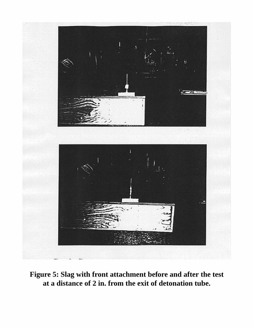
Figure 5: Slag with front attachment before and after the testat a distance of 2 in. from the exit of detonation tube.
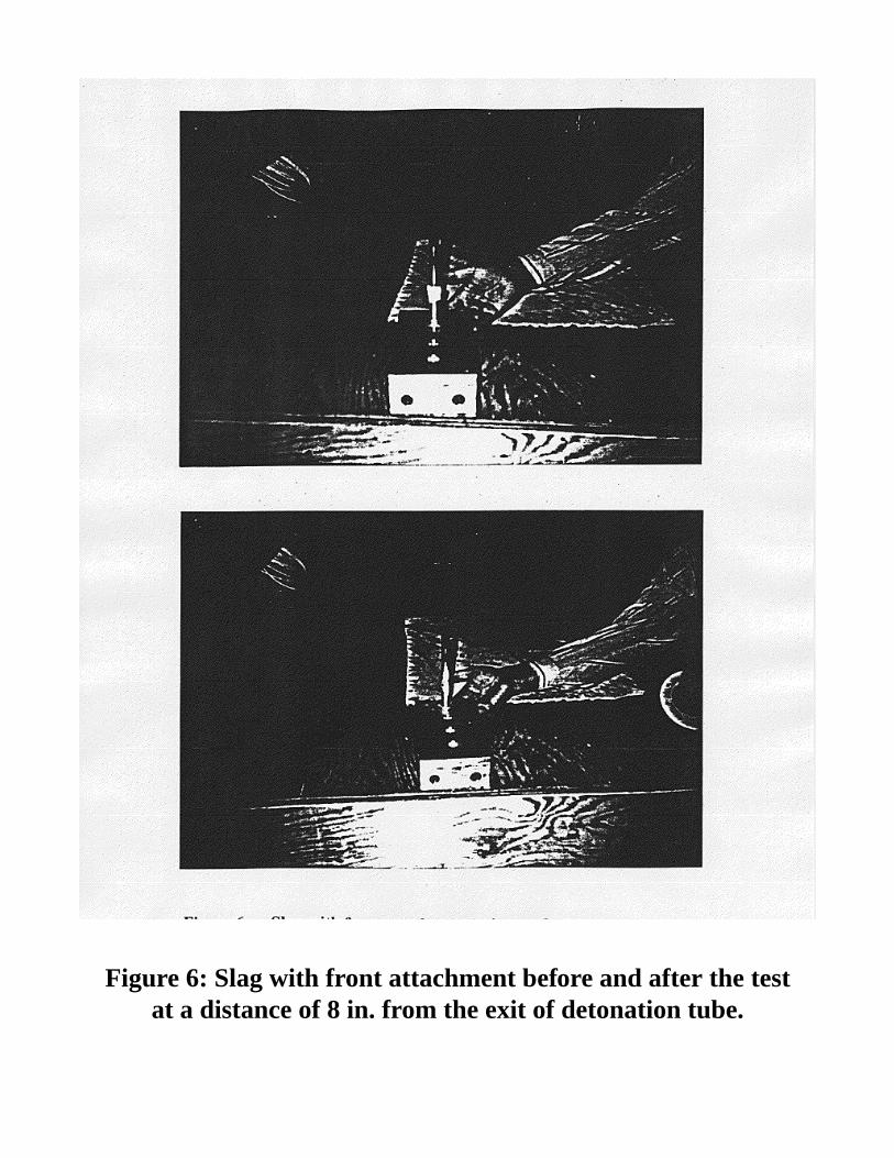
Figure 6: Slag with front attachment before and after the testat a distance of 8 in. from the exit of detonation tube.
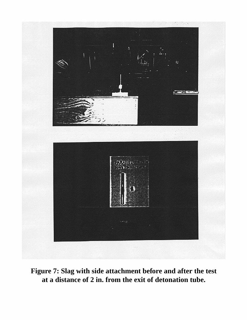
Figure 7: Slag with side attachment before and after the testat a distance of 2 in. from the exit of detonation tube.
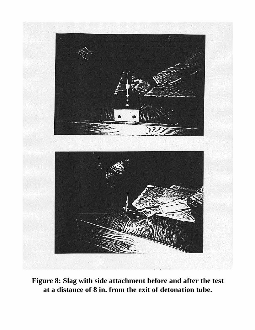
Figure 8: Slag with side attachment before and after the testat a distance of 8 in. from the exit of detonation tube.


![Cars List for SBB V33.02 一,immobilizer · 6 ka[mk] 96-97; ka[mkb] 96-97; mondeo 95-96; mondeo 01-02; mondeo[mk] 96-97; mondeo[mkb] 96-97; mondeo [mkd] 96-97; mondeo[2k] 97-00;](https://img.pdfslide.us/doc/110x75/5c29dd7809d3f292178b5517/cars-list-for-sbb-v3302-6-kamk-96-97-kamkb-96-97-mondeo-95-96.jpg)