Embed Size (px)
Citation preview
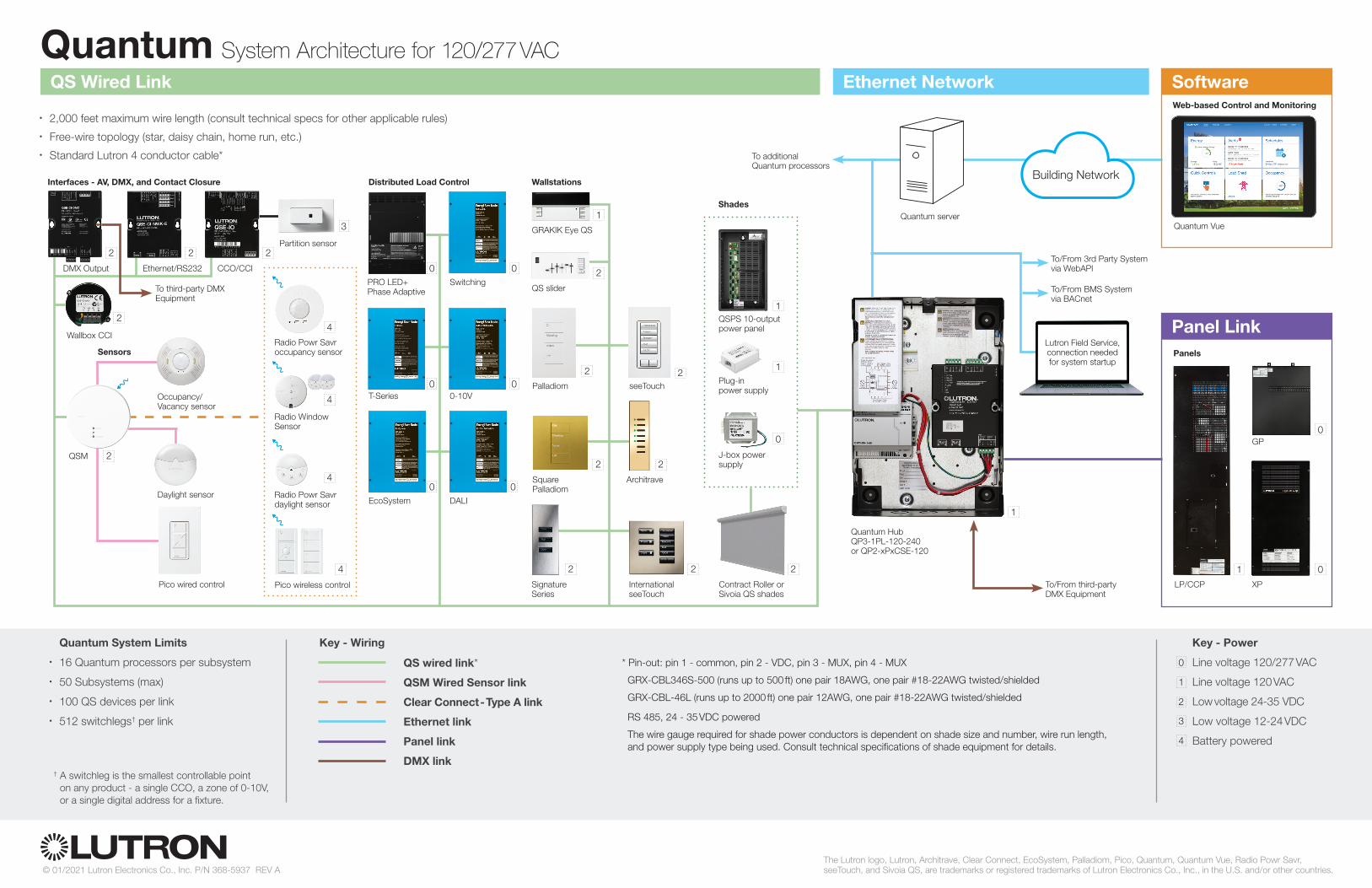
Quantum System Architecture for 120/277 VAC
© 01/2021 Lutron Electronics Co., Inc. P/N 368-5937 REV A The Lutron logo, Lutron, Architrave, Clear Connect, EcoSystem, Palladiom, Pico, Quantum, Quantum Vue, Radio Powr Savr, seeTouch, and Sivoia QS, are trademarks or registered trademarks of Lutron Electronics Co., Inc., in the U.S. and/or other countries.
† A switchleg is the smallest controllable point on any product - a single CCO, a zone of 0-10V, or a single digital address for a fixture.
* Pin-out: pin 1 - common, pin 2 - VDC, pin 3 - MUX, pin 4 - MUX
GRX-CBL346S-500 (runs up to 500 ft) one pair 18AWG, one pair #18-22AWG twisted/shielded
GRX-CBL-46L (runs up to 2000 ft) one pair 12AWG, one pair #18-22AWG twisted/shielded
RS 485, 24 - 35 VDC powered
The wire gauge required for shade power conductors is dependent on shade size and number, wire run length, and power supply type being used. Consult technical specifications of shade equipment for details.
Key - Power
Line voltage 120/277 VAC
Line voltage 120 VAC
Low voltage 24 -35 VDC
Low voltage 12-24 VDC
Battery powered
1
0
2
3
4
Key - Wiring
QS wired link*
QSM Wired Sensor link
Clear Connect - Type A link
Ethernet link
Panel link
DMX link
QS Wired Link
Panel Link
DMX Output
QSM 2
Wallbox CCI
2
Interfaces - AV, DMX, and Contact Closure Distributed Load Control
Sensors
Radio Powr Savr daylight sensor
Occupancy/Vacancy sensor
Daylight sensor
Pico wireless control
Radio Powr Savr occupancy sensor
4
4
4
Wallstations
seeTouch
2
International seeTouch
2
Architrave
2
Signature Series
2
Pico wired control
Palladiom
2
Square Palladiom
2
0
J-box power supply
1QSPS 10-output power panel
Plug-in power supply
1
2
Contract Roller or Sivoia QS shades
Shades
• 2,000 feet maximum wire length (consult technical specs for other applicable rules)• Free-wire topology (star, daisy chain, home run, etc.)• Standard Lutron 4 conductor cable*
Panels
Quantum server
LP/CCP
3
Partition sensor
00-10V
EcoSystem
0DALI
0
T-Series0
2
Radio Window Sensor
4
Quantum System Limits
• 16 Quantum processors per subsystem
• 50 Subsystems (max)
• 100 QS devices per link
• 512 switchlegs† per link
QS slider
2CCO/CCI
2
0PRO LED+ Phase Adaptive
0Switching
GRAKIK Eye QS
1
GP
XP
Building Network
To additional Quantum processors
To/From third-party DMX Equipment
Ethernet/RS232
2
SoftwareWeb-based Control and Monitoring
Quantum Vue
To third-party DMX Equipment
Quantum Hub QP3-1PL-120-240or QP2-xPxCSE-120
1
To/From BMS System via BACnet
Ethernet Network
1 0
0
Lutron Field Service, connection needed for system startup
To/From 3rd Party Systemvia WebAPI