Embed Size (px)
Citation preview
Quantum®
Quick Reference Guide
®
A summary of the most frequently used features in the Quantum® software by facilities managers
®
ContentsQ-AdminTM 1
Scene Changes How do I modify a scene in a selected space / zone?Tabular View 2Graphical View 3Control 4
Occupancy Modification How do I modify the settings of a selected occupancy sensor? 6
Daylight Target Set-Point Modification If someone complains that their lights are too low in a space with Daylighting, what can I do?
Control 7Dimmed 8Switched 9
Time Clock Changes How do I define what lights will do (turn on / turn off / dim) based on area occupancy and time of day?
Control 10View Time Clocks 11Create / Modify Time Clocks 12Test Time Clocks 17Enable/Disable Selected Time Clocks 18Review/Edit Location Settings 19
Diagnostics How do I know when a lamp or ballast has failed?Load Shedding 20Check Status 21
Reports What reports can I generate? How do I generate them?Open a Report 22Save, Print, and Export a Report 23Options 24Lighting Energy Usage Report 25Lighting Power Usage Report 26Lighting Power Trend Comparison Report 27Lamp Maintenance Report 28System Activity Report 29Diagnostics Report 30Sensor Connection Report 31DALI Emergency Units Report 32
HyperionTM Solar Clock Modification How do I change the times that my shades move?Overview 33Control 34Setup 36
Ballast Replacement How do I replace faulty ballasts? 42
Q-DesignTM 45Area Modification How do I rename an area? 46
Control Replacement How do I add or replace an Occupancy sensor or Pico® control to a space? 47
Contact Information 48
Quantum® Quick Reference Guide 1®
Q-AdminTM Software
2 Quantum® Quick Reference Guide®
Scene Changes: Tabular View
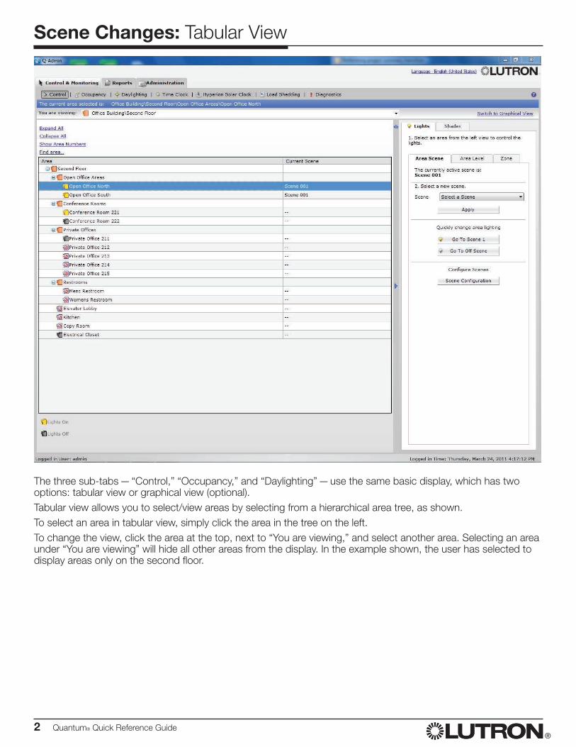
The three sub-tabs — “Control,” “Occupancy,” and “Daylighting” — use the same basic display, which has two options: tabular view or graphical view (optional).Tabular view allows you to select/view areas by selecting from a hierarchical area tree, as shown.To select an area in tabular view, simply click the area in the tree on the left.To change the view, click the area at the top, next to “You are viewing,” and select another area. Selecting an area under “You are viewing” will hide all other areas from the display. In the example shown, the user has selected to display areas only on the second floor.
Quantum® Quick Reference Guide 3®
Scene Changes: Graphical View
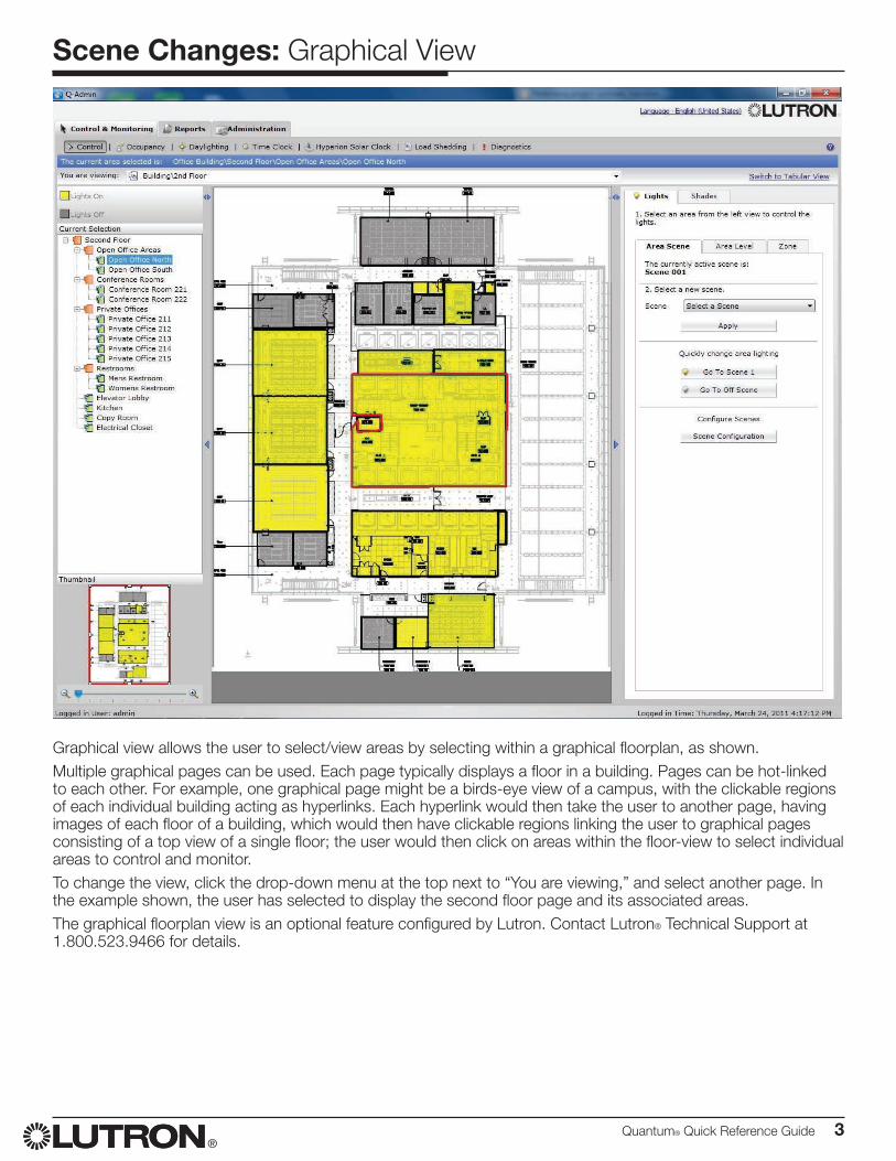
Graphical view allows the user to select/view areas by selecting within a graphical floorplan, as shown.Multiple graphical pages can be used. Each page typically displays a floor in a building. Pages can be hot-linked to each other. For example, one graphical page might be a birds-eye view of a campus, with the clickable regions of each individual building acting as hyperlinks. Each hyperlink would then take the user to another page, having images of each floor of a building, which would then have clickable regions linking the user to graphical pages consisting of a top view of a single floor; the user would then click on areas within the floor-view to select individual areas to control and monitor.To change the view, click the drop-down menu at the top next to “You are viewing,” and select another page. In the example shown, the user has selected to display the second floor page and its associated areas.The graphical floorplan view is an optional feature configured by Lutron. Contact Lutron® Technical Support at 1.800.523.9466 for details.
4 Quantum® Quick Reference Guide®
Scene Changes: Control
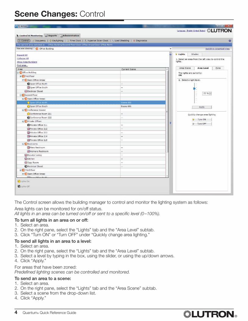
The Control screen allows the building manager to control and monitor the lighting system as follows:Area lights can be monitored for on/off status.All lights in an area can be turned on/off or sent to a specific level (0 –100%). To turn all lights in an area on or off:1. Select an area.2. On the right pane, select the “Lights” tab and the “Area Level” subtab.3. Click “Turn ON” or “Turn OFF” under “Quickly change area lighting.”To send all lights in an area to a level:1. Select an area.2. On the right pane, select the “Lights” tab and the “Area Level” subtab.3. Select a level by typing in the box, using the slider, or using the up/down arrows.4. Click “Apply.”For areas that have been zoned:Predefined lighting scenes can be controlled and monitored.To send an area to a scene:1. Select an area.2. On the right pane, select the “Lights” tab and the “Area Scene” subtab.3. Select a scene from the drop-down list.4. Click “Apply.”
Quantum® Quick Reference Guide 5®
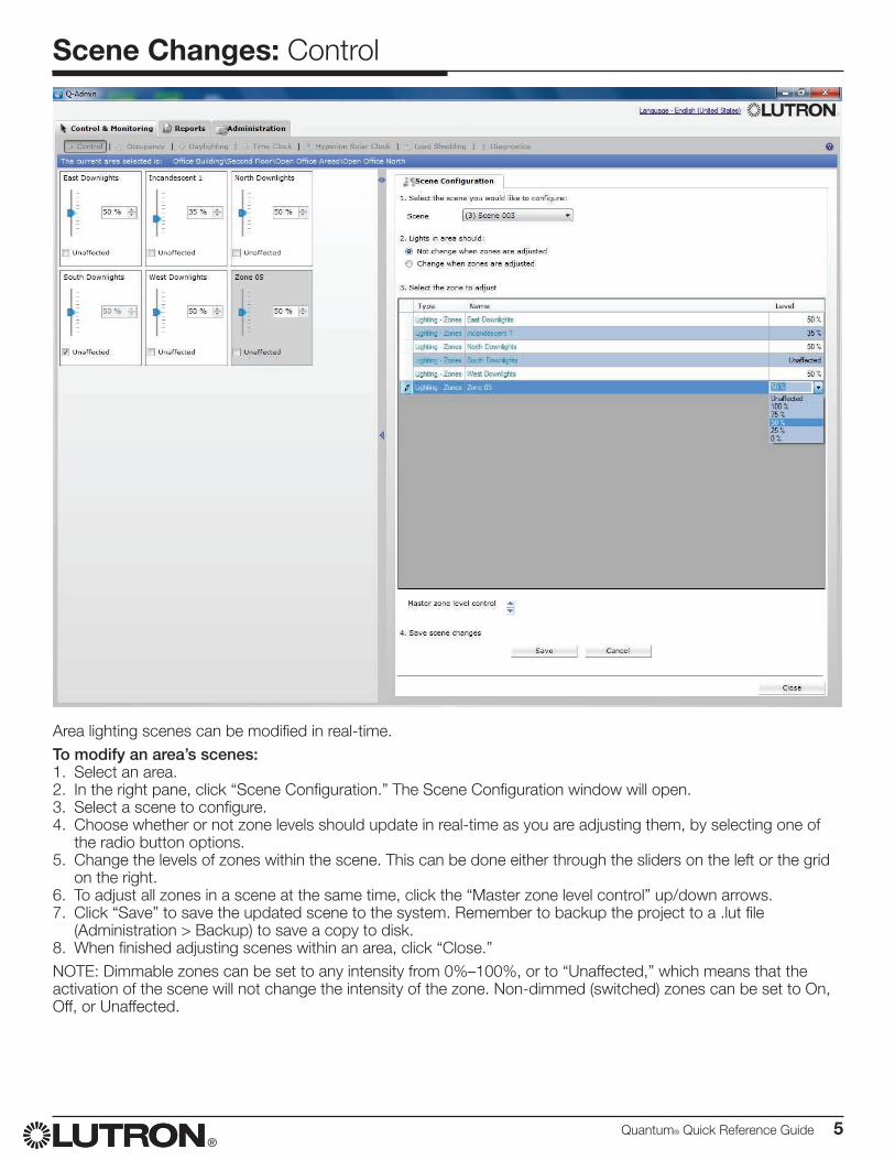
Area lighting scenes can be modified in real-time.To modify an area’s scenes:1. Select an area.2. In the right pane, click “Scene Configuration.” The Scene Configuration window will open.3. Select a scene to configure.4. Choose whether or not zone levels should update in real-time as you are adjusting them, by selecting one of
the radio button options.5. Change the levels of zones within the scene. This can be done either through the sliders on the left or the grid
on the right.6. To adjust all zones in a scene at the same time, click the “Master zone level control” up/down arrows.7. Click “Save” to save the updated scene to the system. Remember to backup the project to a .lut file
(Administration > Backup) to save a copy to disk.8. When finished adjusting scenes within an area, click “Close.”NOTE: Dimmable zones can be set to any intensity from 0%–100%, or to “Unaffected,” which means that the activation of the scene will not change the intensity of the zone. Non-dimmed (switched) zones can be set to On, Off, or Unaffected.
Scene Changes: Control
6 Quantum® Quick Reference Guide®
Occupancy Modification
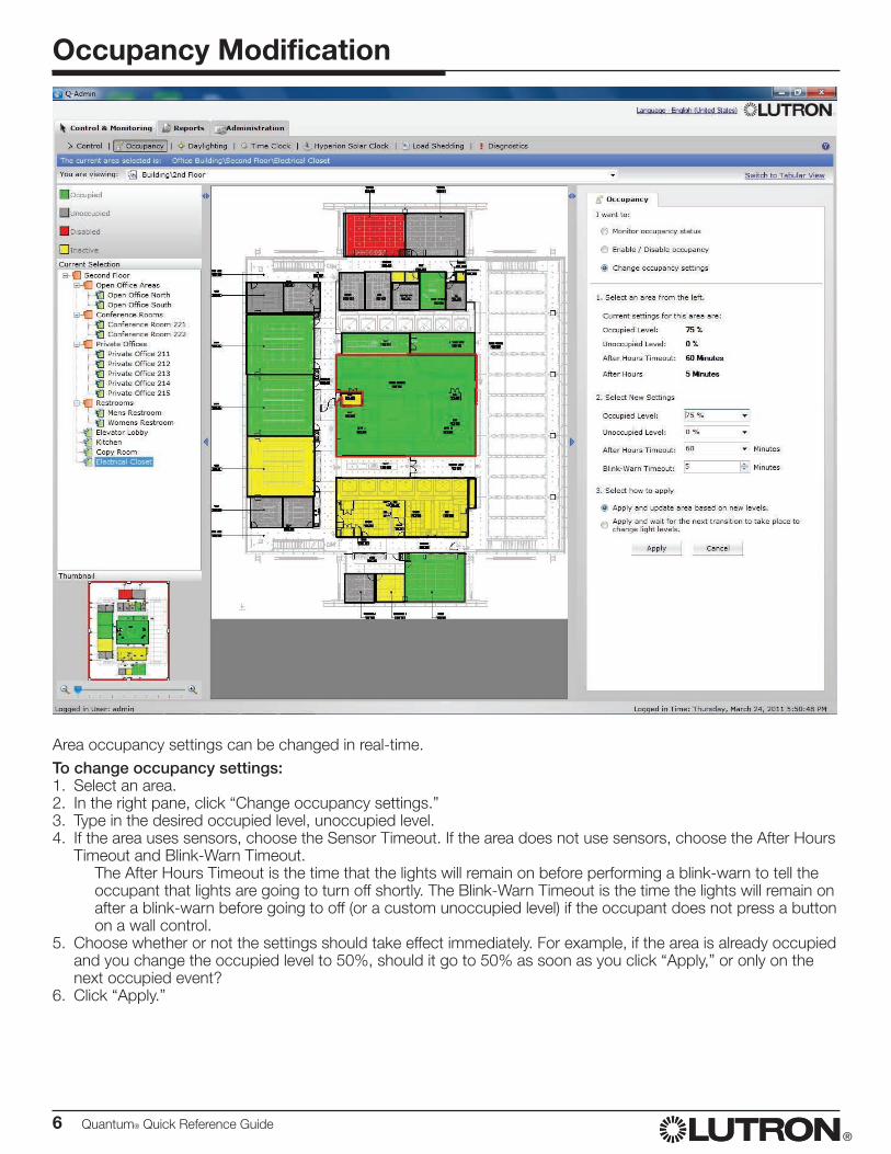
Area occupancy settings can be changed in real-time.To change occupancy settings:1. Select an area.2. In the right pane, click “Change occupancy settings.”3. Type in the desired occupied level, unoccupied level.4. If the area uses sensors, choose the Sensor Timeout. If the area does not use sensors, choose the After Hours
Timeout and Blink-Warn Timeout. The After Hours Timeout is the time that the lights will remain on before performing a blink-warn to tell the
occupant that lights are going to turn off shortly. The Blink-Warn Timeout is the time the lights will remain on after a blink-warn before going to off (or a custom unoccupied level) if the occupant does not press a button on a wall control.
5. Choose whether or not the settings should take effect immediately. For example, if the area is already occupied and you change the occupied level to 50%, should it go to 50% as soon as you click “Apply,” or only on the next occupied event?
6. Click “Apply.”
Quantum® Quick Reference Guide 7®
Daylight Target Set-Point Modification: Control
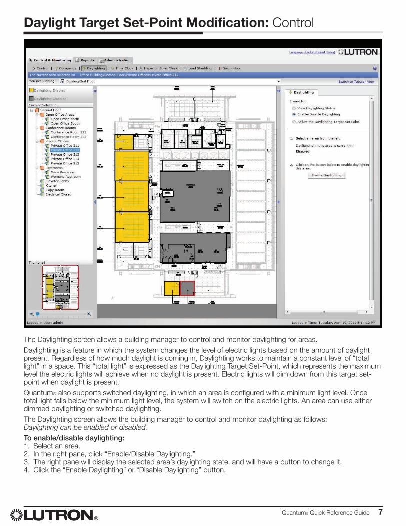
The Daylighting screen allows a building manager to control and monitor daylighting for areas.Daylighting is a feature in which the system changes the level of electric lights based on the amount of daylight present. Regardless of how much daylight is coming in, Daylighting works to maintain a constant level of “total light” in a space. This “total light” is expressed as the Daylighting Target Set-Point, which represents the maximum level the electric lights will achieve when no daylight is present. Electric lights will dim down from this target set-point when daylight is present.Quantum® also supports switched daylighting, in which an area is configured with a minimum light level. Once total light falls below the minimum light level, the system will switch on the electric lights. An area can use either dimmed daylighting or switched daylighting.The Daylighting screen allows the building manager to control and monitor daylighting as follows:Daylighting can be enabled or disabled.To enable/disable daylighting:1. Select an area.2. In the right pane, click “Enable/Disable Daylighting.”3. The right pane will display the selected area’s daylighting state, and will have a button to change it.4. Click the “Enable Daylighting” or “Disable Daylighting” button.
8 Quantum® Quick Reference Guide®
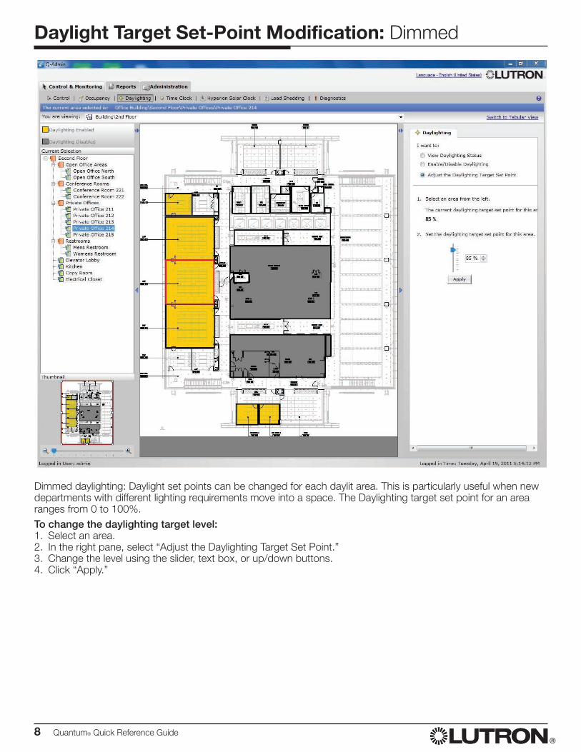
Daylight Target Set-Point Modification: Dimmed
Dimmed daylighting: Daylight set points can be changed for each daylit area. This is particularly useful when new departments with different lighting requirements move into a space. The Daylighting target set point for an area ranges from 0 to 100%.To change the daylighting target level:1. Select an area.2. In the right pane, select “Adjust the Daylighting Target Set Point.”3. Change the level using the slider, text box, or up/down buttons.4. Click “Apply.”
Quantum® Quick Reference Guide 9®
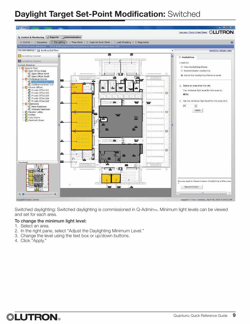
Daylight Target Set-Point Modification: Switched
Switched daylighting: Switched daylighting is commissioned in Q-AdminTM. Minimum light levels can be viewed and set for each area.To change the minimum light level:1. Select an area.2. In the right pane, select “Adjust the Daylighting Minimum Level.” 3. Change the level using the text box or up/down buttons.4. Click “Apply.”
10 Quantum® Quick Reference Guide®
Time Clock Changes: ControlTime Clocks are defined to allow automated control of the system via programmed time clock events.Multiple time clocks are used to separate control of different areas or different output types (lighting, shades, etc.).You may, for example, define a separate time clock for each of the following:• Campus Parking Lot Lights• Shades• Cafeteria LightsBelow is an example showing how you might define the “Campus Parking Lot Lights Time Clock”:
Campus Parking Lot Lights Time Clock1. Assign Outputs to Time Clock I want to control all my exterior parking lot areas, which include:• Exterior\Parking Lot 1• Exterior\Parking Lot 2• Exterior\Parking Lot 3
2. Define Weekly Events During a normal week, I want my Campus Parking Lot Lights to operate as follows:
Time Event Name Days of the Week
One hour Before Sunrise Turn Lights On Monday – Friday
Sunrise Turn Lights Off Monday – Friday
Sunset Turn Lights On Monday – Friday
1:00 AM Turn Lights Off Monday – Friday
3. Define Special Events During a holiday, I want my Campus Parking Lot Lights to operate as follows:
Time Event Name
Sunset Turn Lights On
10:30 PM Turn Lights Off
Other Time Clock ApplicationsAfter Hours Time Clock
Time Event Name Days of the Week
7:00 AM Begin After Hours Monday – Friday
7:00 PM End After Hours Monday – Friday
Disable Nighttime Occupancy Time Clock
Time Event Name Days of the Week
7:00 AM Disable Occupancy Monday – Friday
7:00 PM Enable Occupancy Monday – Friday
Quantum® Quick Reference Guide 11®
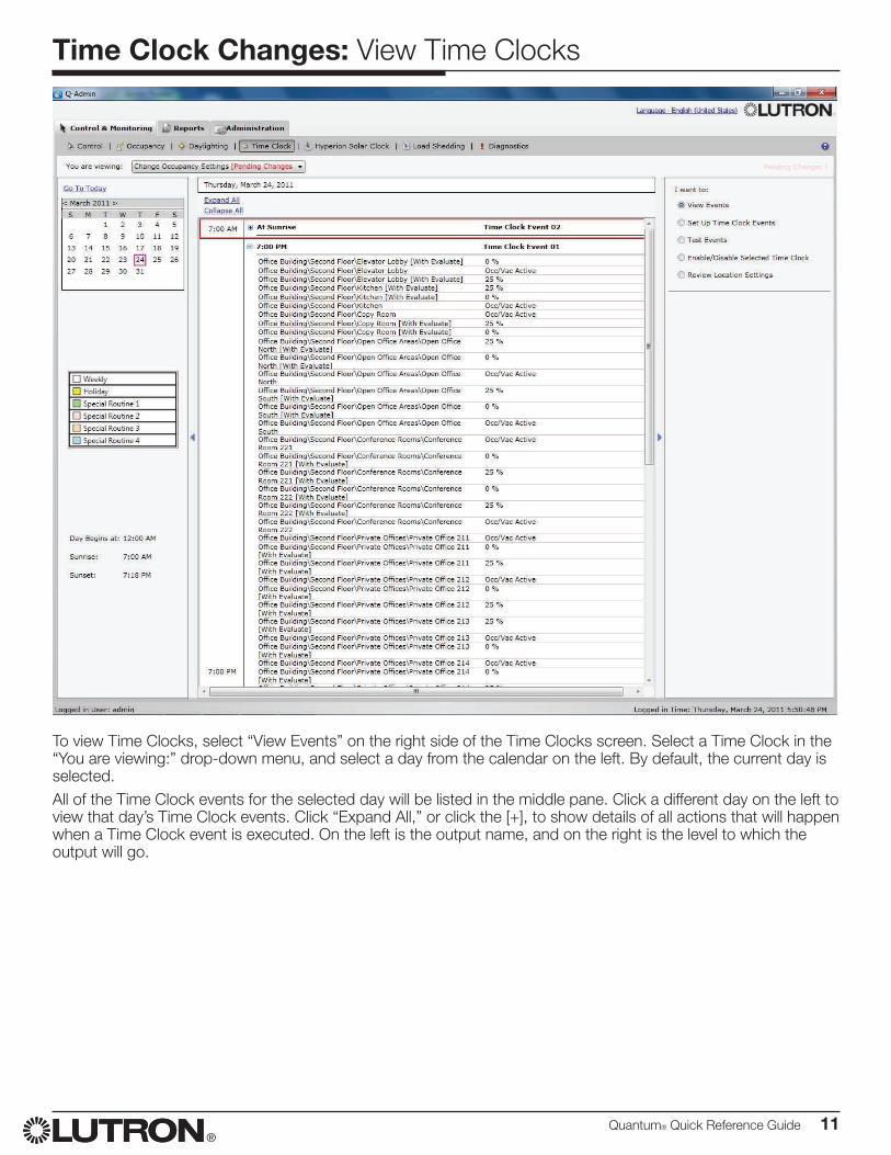
Time Clock Changes: View Time Clocks
To view Time Clocks, select “View Events” on the right side of the Time Clocks screen. Select a Time Clock in the “You are viewing:” drop-down menu, and select a day from the calendar on the left. By default, the current day is selected.All of the Time Clock events for the selected day will be listed in the middle pane. Click a different day on the left to view that day’s Time Clock events. Click “Expand All,” or click the [+], to show details of all actions that will happen when a Time Clock event is executed. On the left is the output name, and on the right is the level to which the output will go.
12 Quantum® Quick Reference Guide®
Time Clock Changes: Create/Modify Time Clocks
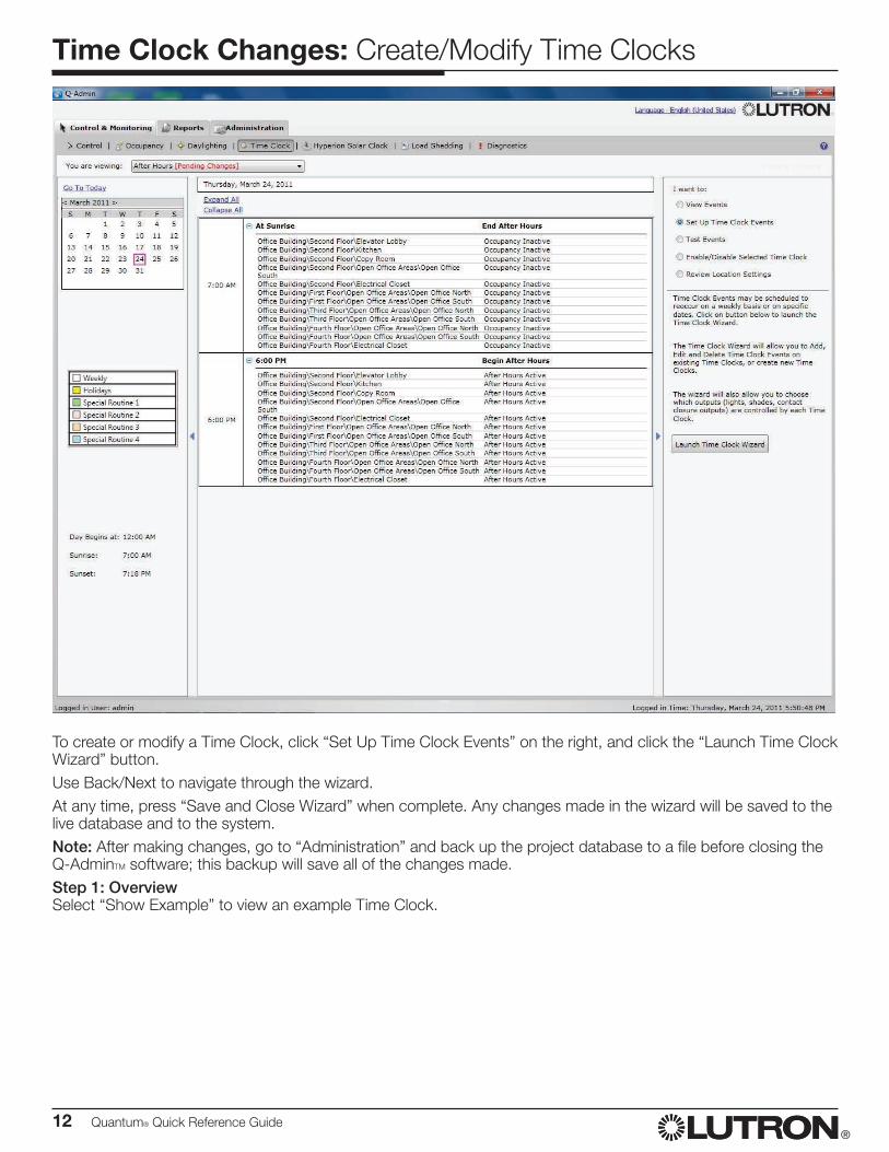
To create or modify a Time Clock, click “Set Up Time Clock Events” on the right, and click the “Launch Time Clock Wizard” button.Use Back/Next to navigate through the wizard.At any time, press “Save and Close Wizard” when complete. Any changes made in the wizard will be saved to the live database and to the system.Note: After making changes, go to “Administration” and back up the project database to a file before closing the Q-AdminTM software; this backup will save all of the changes made.Step 1: OverviewSelect “Show Example” to view an example Time Clock.
Quantum® Quick Reference Guide 13®
Time Clock Changes: Create/Modify Time Clocks
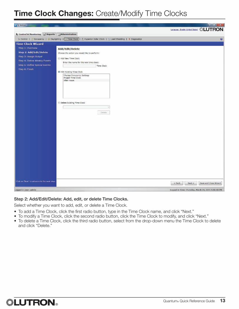
Step 2: Add/Edit/Delete: Add, edit, or delete Time Clocks.Select whether you want to add, edit, or delete a Time Clock.• To add a Time Clock, click the first radio button, type in the Time Clock name, and click “Next.”• To modify a Time Clock, click the second radio button, click the Time Clock to modify, and click “Next.”• To delete a Time Clock, click the third radio button, select from the drop-down menu the Time Clock to delete
and click “Delete.”
14 Quantum® Quick Reference Guide®
Time Clock Changes: Create/Modify Time Clocks
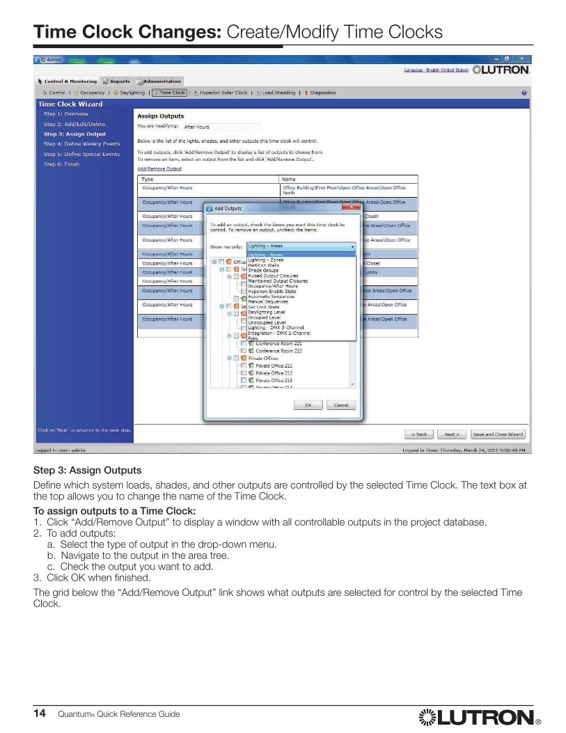
Step 3: Assign OutputsDefine which system loads, shades, and other outputs are controlled by the selected Time Clock. The text box at the top allows you to change the name of the Time Clock.To assign outputs to a Time Clock:1. Click “Add/Remove Output” to display a window with all controllable outputs in the project database.2. To add outputs: a. Select the type of output in the drop-down menu. b. Navigate to the output in the area tree. c. Check the output you want to add.3. Click OK when finished.The grid below the “Add/Remove Output” link shows what outputs are selected for control by the selected Time Clock.
Quantum® Quick Reference Guide 15®
Time Clock Changes: Create/Modify Time Clocks
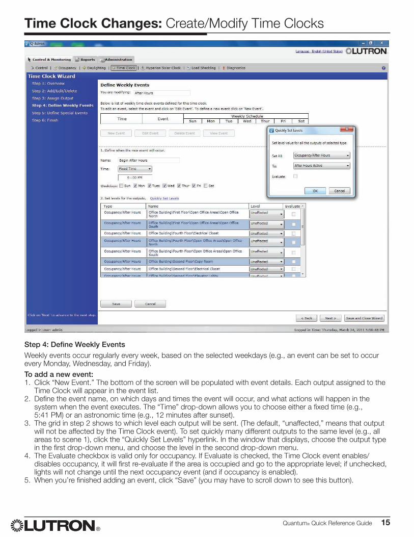
Step 4: Define Weekly EventsWeekly events occur regularly every week, based on the selected weekdays (e.g., an event can be set to occur every Monday, Wednesday, and Friday). To add a new event:1. Click “New Event.” The bottom of the screen will be populated with event details. Each output assigned to the
Time Clock will appear in the event list.2. Define the event name, on which days and times the event will occur, and what actions will happen in the
system when the event executes. The “Time” drop-down allows you to choose either a fixed time (e.g., 5:41 PM) or an astronomic time (e.g., 12 minutes after sunset).
3. The grid in step 2 shows to which level each output will be sent. (The default, “unaffected,” means that output will not be affected by the Time Clock event). To set quickly many different outputs to the same level (e.g., all areas to scene 1), click the “Quickly Set Levels” hyperlink. In the window that displays, choose the output type in the first drop-down menu, and choose the level in the second drop-down menu.
4. The Evaluate checkbox is valid only for occupancy. If Evaluate is checked, the Time Clock event enables/disables occupancy, it will first re-evaluate if the area is occupied and go to the appropriate level; if unchecked, lights will not change until the next occupancy event (and if occupancy is enabled).
5. When you’re finished adding an event, click “Save” (you may have to scroll down to see this button).
16 Quantum® Quick Reference Guide®
Time Clock Changes: Create/Modify Time Clocks
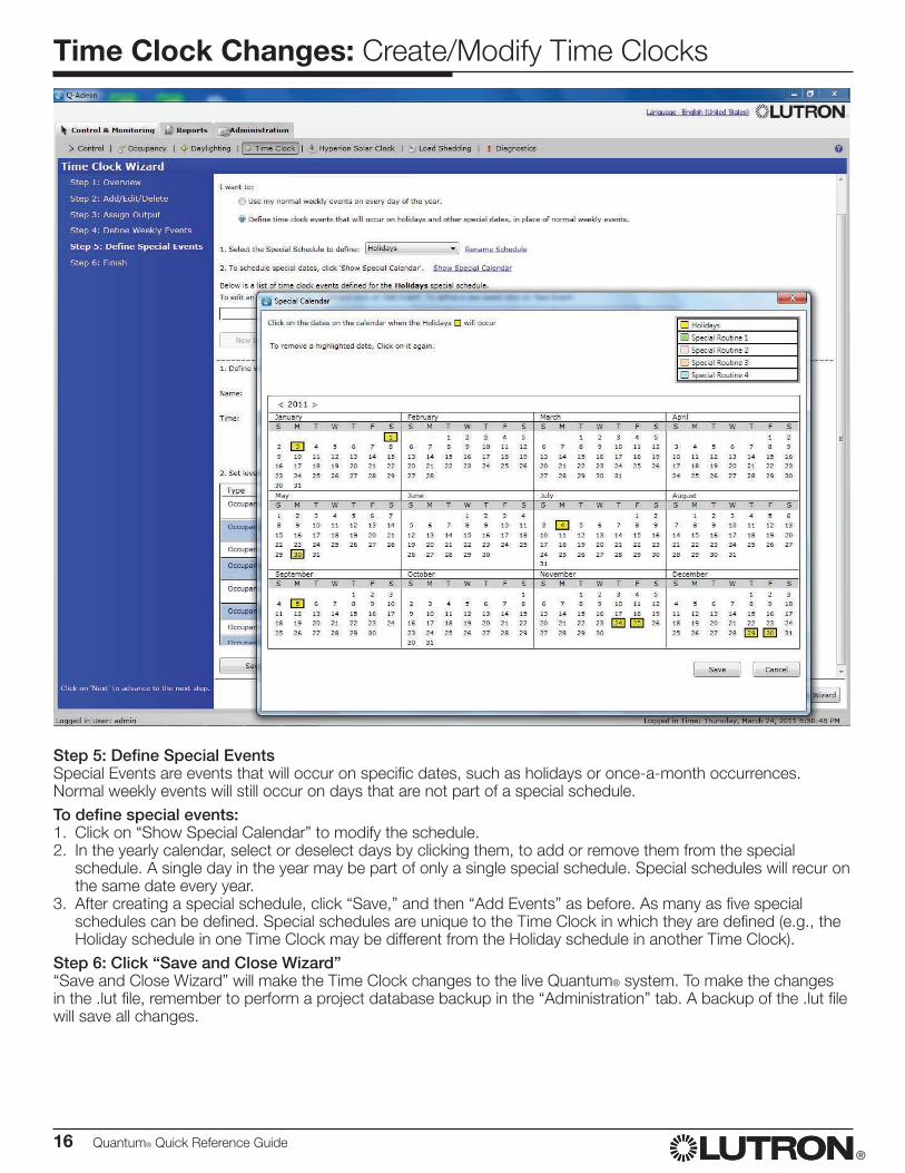
Step 5: Define Special EventsSpecial Events are events that will occur on specific dates, such as holidays or once-a-month occurrences. Normal weekly events will still occur on days that are not part of a special schedule.To define special events:1. Click on “Show Special Calendar” to modify the schedule.2. In the yearly calendar, select or deselect days by clicking them, to add or remove them from the special
schedule. A single day in the year may be part of only a single special schedule. Special schedules will recur on the same date every year.
3. After creating a special schedule, click “Save,” and then “Add Events” as before. As many as five special schedules can be defined. Special schedules are unique to the Time Clock in which they are defined (e.g., the Holiday schedule in one Time Clock may be different from the Holiday schedule in another Time Clock).
Step 6: Click “Save and Close Wizard”“Save and Close Wizard” will make the Time Clock changes to the live Quantum® system. To make the changes in the .lut file, remember to perform a project database backup in the “Administration” tab. A backup of the .lut file will save all changes.
Quantum® Quick Reference Guide 17®
Time Clock Changes: Test Time Clocks
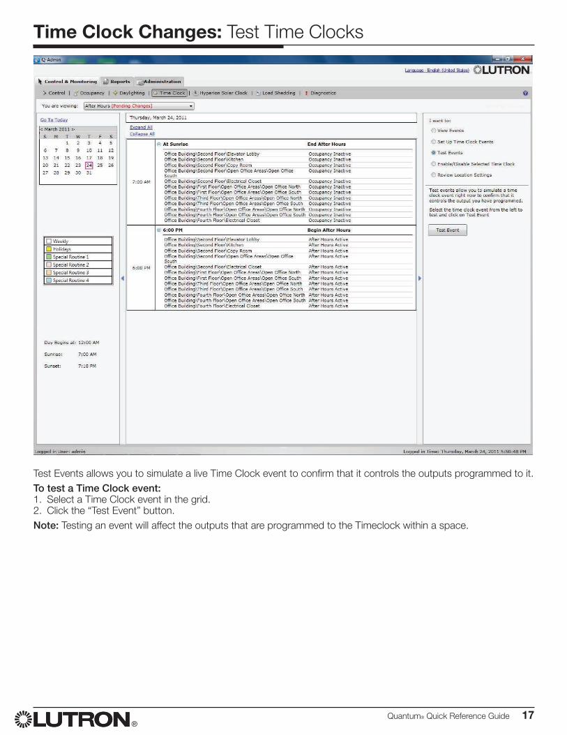
Test Events allows you to simulate a live Time Clock event to confirm that it controls the outputs programmed to it.To test a Time Clock event:1. Select a Time Clock event in the grid.2. Click the “Test Event” button.Note: Testing an event will affect the outputs that are programmed to the Timeclock within a space.
18 Quantum® Quick Reference Guide®
Time Clock Changes: Enable/Disable Selected Time Clocks
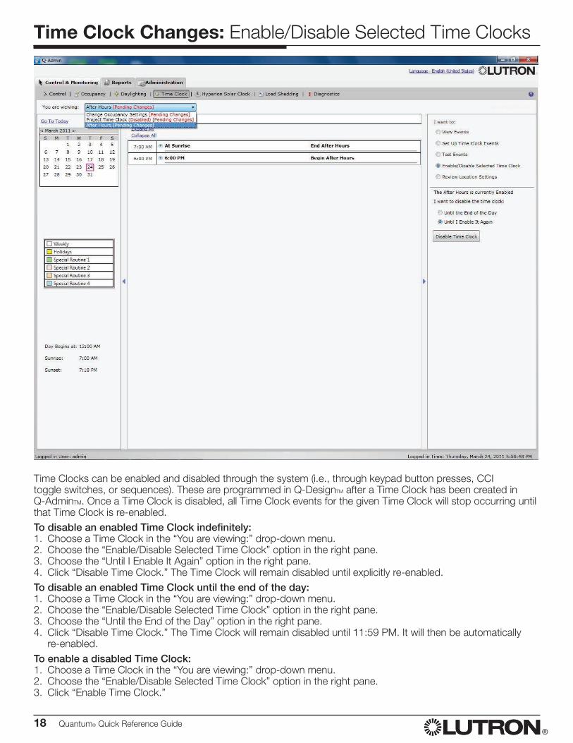
Time Clocks can be enabled and disabled through the system (i.e., through keypad button presses, CCI toggle switches, or sequences). These are programmed in Q-DesignTM after a Time Clock has been created in Q-AdminTM. Once a Time Clock is disabled, all Time Clock events for the given Time Clock will stop occurring until that Time Clock is re-enabled.To disable an enabled Time Clock indefinitely:1. Choose a Time Clock in the “You are viewing:” drop-down menu.2. Choose the “Enable/Disable Selected Time Clock” option in the right pane.3. Choose the “Until I Enable It Again” option in the right pane.4. Click “Disable Time Clock.” The Time Clock will remain disabled until explicitly re-enabled.To disable an enabled Time Clock until the end of the day:1. Choose a Time Clock in the “You are viewing:” drop-down menu.2. Choose the “Enable/Disable Selected Time Clock” option in the right pane.3. Choose the “Until the End of the Day” option in the right pane.4. Click “Disable Time Clock.” The Time Clock will remain disabled until 11:59 PM. It will then be automatically
re-enabled.To enable a disabled Time Clock:1. Choose a Time Clock in the “You are viewing:” drop-down menu.2. Choose the “Enable/Disable Selected Time Clock” option in the right pane.3. Click “Enable Time Clock.”
Quantum® Quick Reference Guide 19®
Time Clock Changes: Review/Edit Location Settings
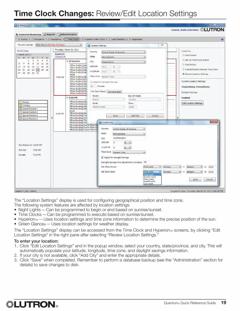
The “Location Settings” display is used for configuring geographical position and time zone.The following system features are affected by location settings:• Night Lights — Can be programmed to begin or end based on sunrise/sunset.• Time Clocks — Can be programmed to execute based on sunrise/sunset.• HyperionTM — Uses location settings and time zone information to determine the precise position of the sun.• Green Glance® — Uses location settings for weather display.The “Location Settings” display can be accessed from the Time Clock and HyperionTM screens, by clicking “Edit Location Settings” in the right pane after selecting “Review Location Settings.”To enter your location:1. Click “Edit Location Settings” and in the popup window, select your country, state/province, and city. This will
automatically populate your latitude, longitude, time zone, and daylight savings information.2. If your city is not available, click “Add City” and enter the appropriate details.3. Click “Save” when completed. Remember to perform a database backup (see the “Administration” section for
details) to save changes to disk.
20 Quantum® Quick Reference Guide®
Diagnostics: Load Shedding
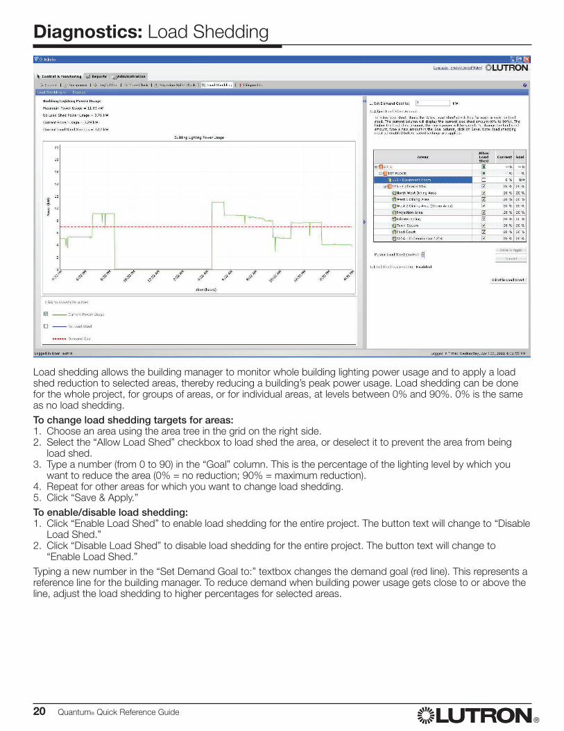
Load shedding allows the building manager to monitor whole building lighting power usage and to apply a load shed reduction to selected areas, thereby reducing a building’s peak power usage. Load shedding can be done for the whole project, for groups of areas, or for individual areas, at levels between 0% and 90%. 0% is the same as no load shedding.To change load shedding targets for areas:1. Choose an area using the area tree in the grid on the right side.2. Select the “Allow Load Shed” checkbox to load shed the area, or deselect it to prevent the area from being
load shed.3. Type a number (from 0 to 90) in the “Goal” column. This is the percentage of the lighting level by which you
want to reduce the area (0% = no reduction; 90% = maximum reduction).4. Repeat for other areas for which you want to change load shedding.5. Click “Save & Apply.”To enable/disable load shedding:1. Click “Enable Load Shed” to enable load shedding for the entire project. The button text will change to “Disable
Load Shed.”2. Click “Disable Load Shed” to disable load shedding for the entire project. The button text will change to
“Enable Load Shed.”Typing a new number in the “Set Demand Goal to:” textbox changes the demand goal (red line). This represents a reference line for the building manager. To reduce demand when building power usage gets close to or above the line, adjust the load shedding to higher percentages for selected areas.
Quantum® Quick Reference Guide 21®
Diagnostics: Check Status
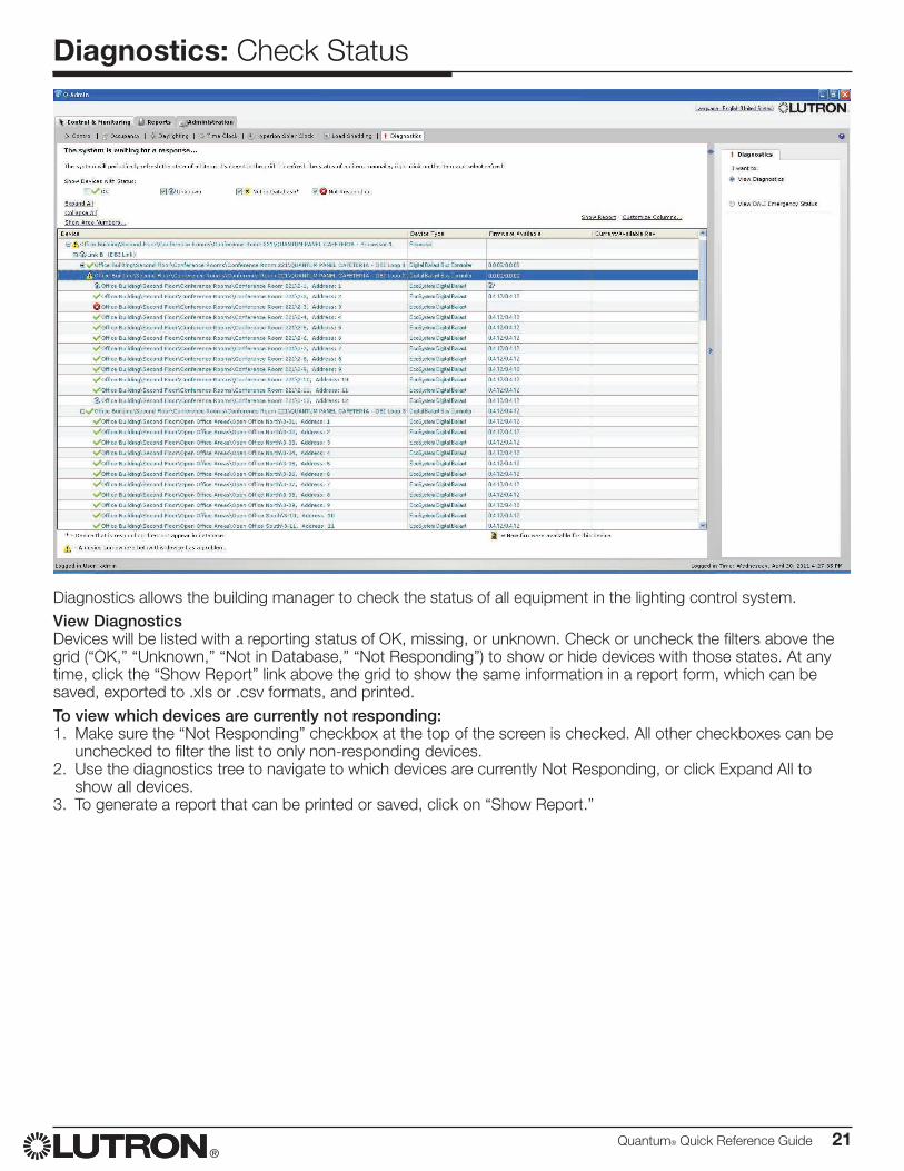
Diagnostics allows the building manager to check the status of all equipment in the lighting control system. View DiagnosticsDevices will be listed with a reporting status of OK, missing, or unknown. Check or uncheck the filters above the grid (“OK,” “Unknown,” “Not in Database,” “Not Responding”) to show or hide devices with those states. At any time, click the “Show Report” link above the grid to show the same information in a report form, which can be saved, exported to .xls or .csv formats, and printed. To view which devices are currently not responding:1. Make sure the “Not Responding” checkbox at the top of the screen is checked. All other checkboxes can be
unchecked to filter the list to only non-responding devices.2. Use the diagnostics tree to navigate to which devices are currently Not Responding, or click Expand All to
show all devices.3. To generate a report that can be printed or saved, click on “Show Report.”
22 Quantum® Quick Reference Guide®
Reports: Open a Report
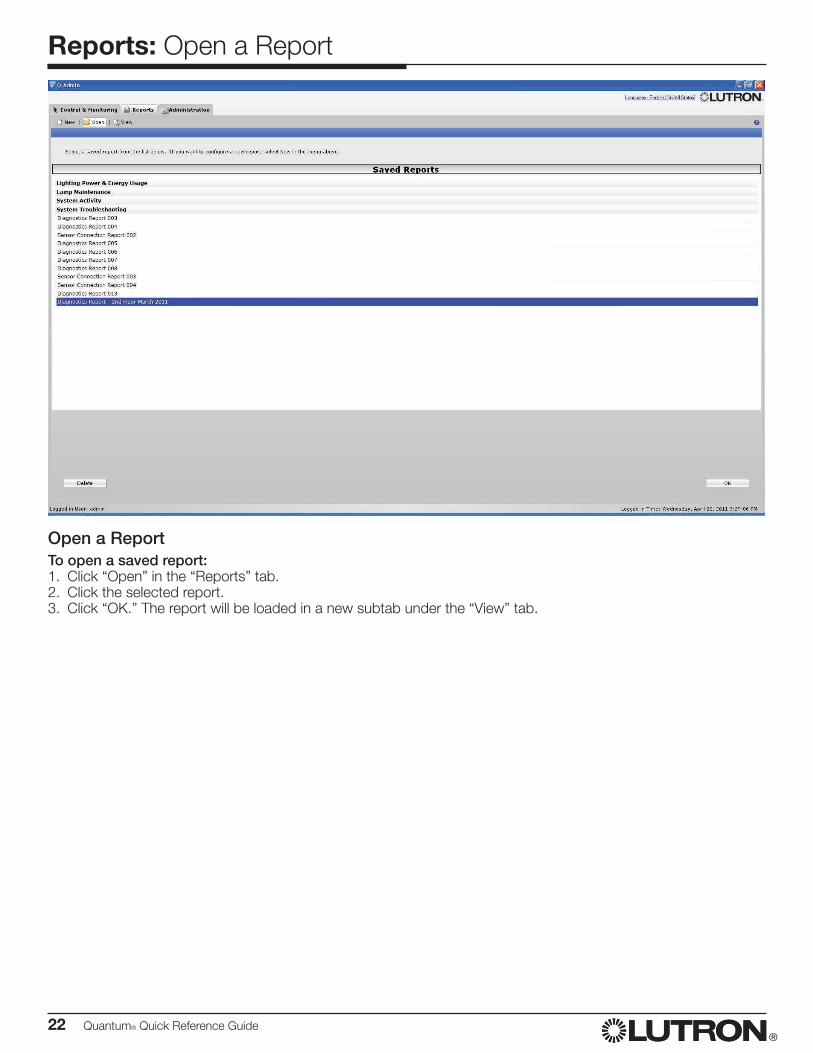
Open a ReportTo open a saved report:1. Click “Open” in the “Reports” tab.2. Click the selected report.3. Click “OK.” The report will be loaded in a new subtab under the “View” tab.
Quantum® Quick Reference Guide 23®
Reports: Save, Print, and Export a Report
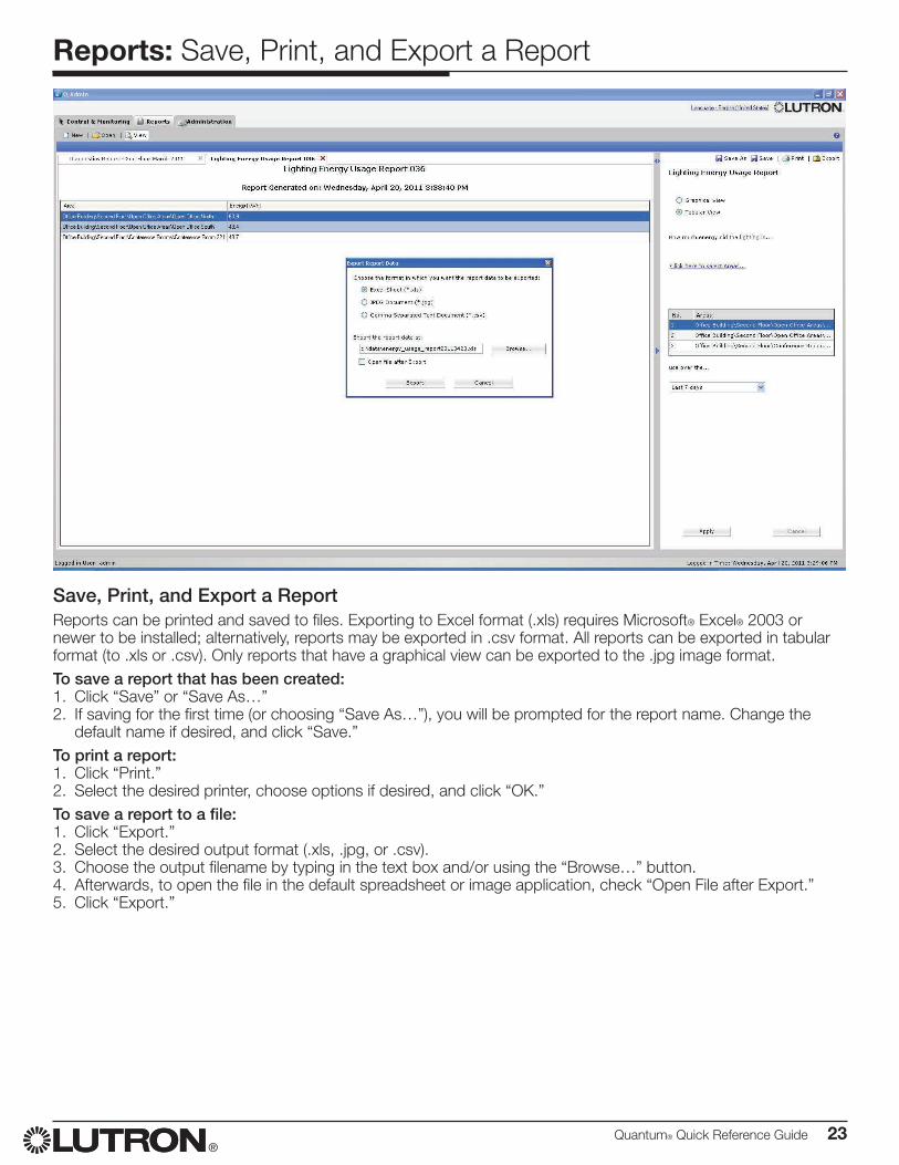
Save, Print, and Export a ReportReports can be printed and saved to files. Exporting to Excel format (.xls) requires Microsoft® Excel® 2003 or newer to be installed; alternatively, reports may be exported in .csv format. All reports can be exported in tabular format (to .xls or .csv). Only reports that have a graphical view can be exported to the .jpg image format.To save a report that has been created:1. Click “Save” or “Save As…”2. If saving for the first time (or choosing “Save As…”), you will be prompted for the report name. Change the
default name if desired, and click “Save.”To print a report:1. Click “Print.”2. Select the desired printer, choose options if desired, and click “OK.”To save a report to a file:1. Click “Export.”2. Select the desired output format (.xls, .jpg, or .csv).3. Choose the output filename by typing in the text box and/or using the “Browse…” button.4. Afterwards, to open the file in the default spreadsheet or image application, check “Open File after Export.”5. Click “Export.”
24 Quantum® Quick Reference Guide®
Reports: Options
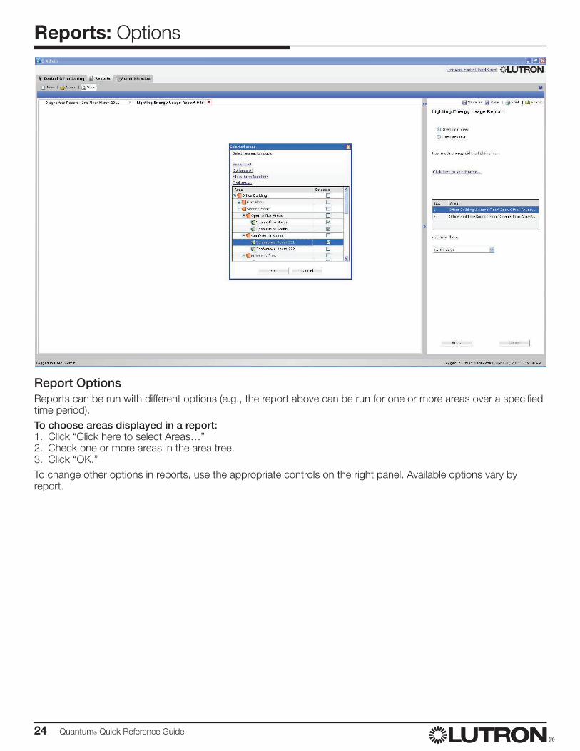
Report OptionsReports can be run with different options (e.g., the report above can be run for one or more areas over a specified time period).To choose areas displayed in a report:1. Click “Click here to select Areas…”2. Check one or more areas in the area tree.3. Click “OK.”To change other options in reports, use the appropriate controls on the right panel. Available options vary by report.
Quantum® Quick Reference Guide 25®
Reports: Lighting Energy Usage Report
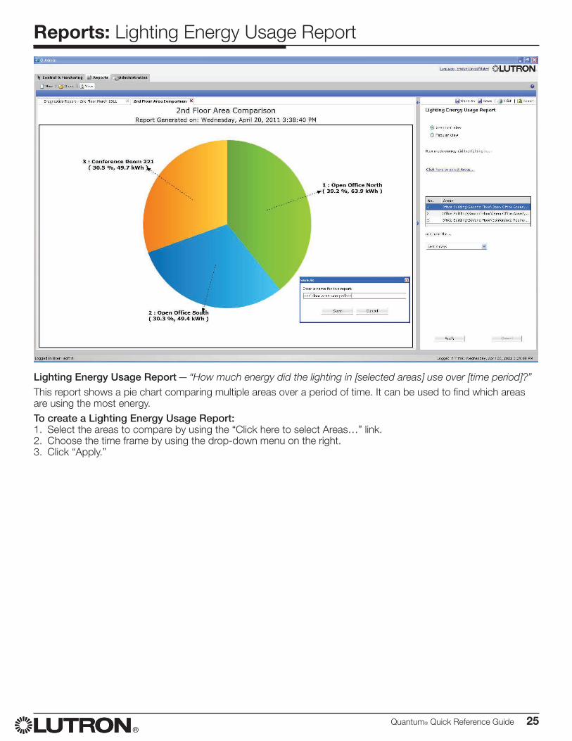
Lighting Energy Usage Report — “How much energy did the lighting in [selected areas] use over [time period]?”This report shows a pie chart comparing multiple areas over a period of time. It can be used to find which areas are using the most energy.To create a Lighting Energy Usage Report:1. Select the areas to compare by using the “Click here to select Areas…” link.2. Choose the time frame by using the drop-down menu on the right.3. Click “Apply.”
26 Quantum® Quick Reference Guide®
Reports: Lighting Power Usage Report
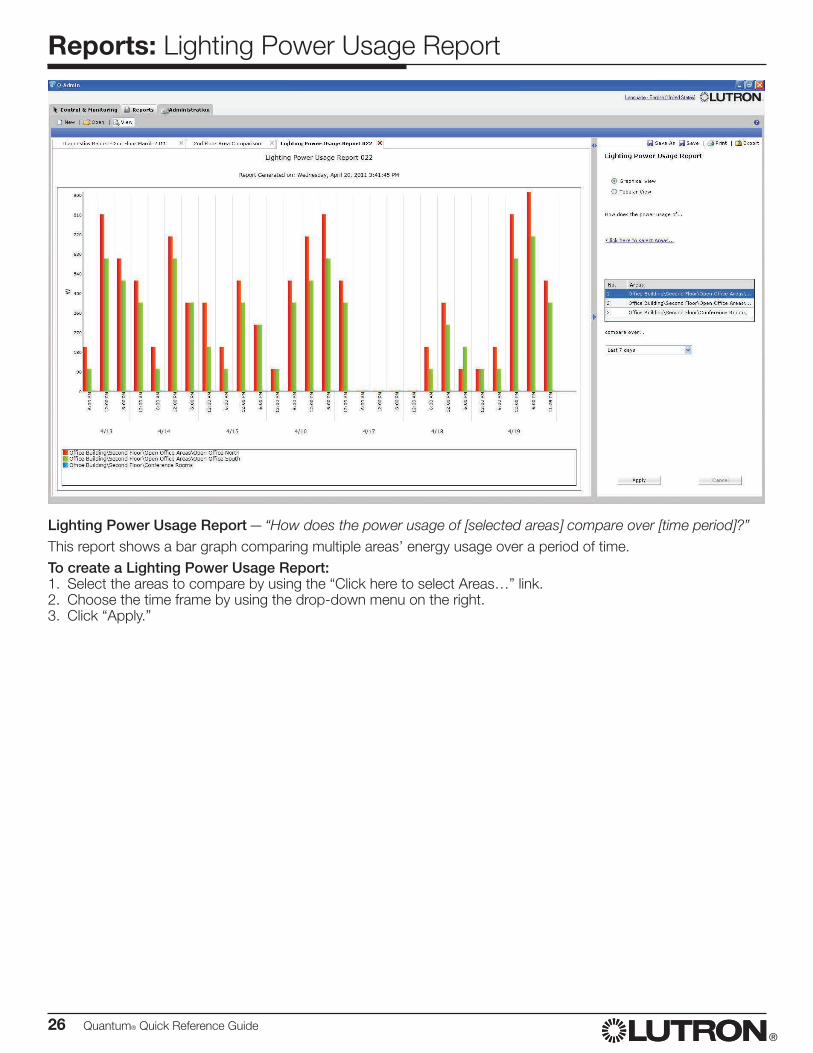
Lighting Power Usage Report — “How does the power usage of [selected areas] compare over [time period]?”This report shows a bar graph comparing multiple areas’ energy usage over a period of time.To create a Lighting Power Usage Report:1. Select the areas to compare by using the “Click here to select Areas…” link.2. Choose the time frame by using the drop-down menu on the right.3. Click “Apply.”
Quantum® Quick Reference Guide 27®
Reports: Lighting Power Trend Comparison Report
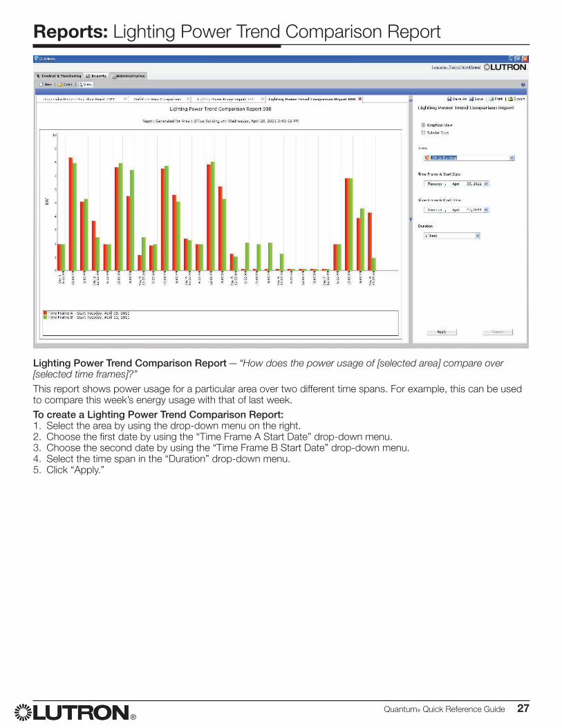
Lighting Power Trend Comparison Report — “How does the power usage of [selected area] compare over [selected time frames]?”This report shows power usage for a particular area over two different time spans. For example, this can be used to compare this week’s energy usage with that of last week.To create a Lighting Power Trend Comparison Report:1. Select the area by using the drop-down menu on the right.2. Choose the first date by using the “Time Frame A Start Date” drop-down menu.3. Choose the second date by using the “Time Frame B Start Date” drop-down menu.4. Select the time span in the “Duration” drop-down menu.5. Click “Apply.”
28 Quantum® Quick Reference Guide®
Reports: Lamp Maintenance Report
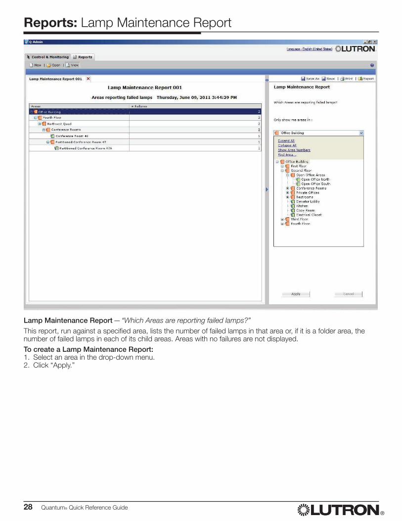
Lamp Maintenance Report — “Which Areas are reporting failed lamps?”This report, run against a specified area, lists the number of failed lamps in that area or, if it is a folder area, the number of failed lamps in each of its child areas. Areas with no failures are not displayed.To create a Lamp Maintenance Report:1. Select an area in the drop-down menu.2. Click “Apply.”
Quantum® Quick Reference Guide 29®
Reports: System Activity Report
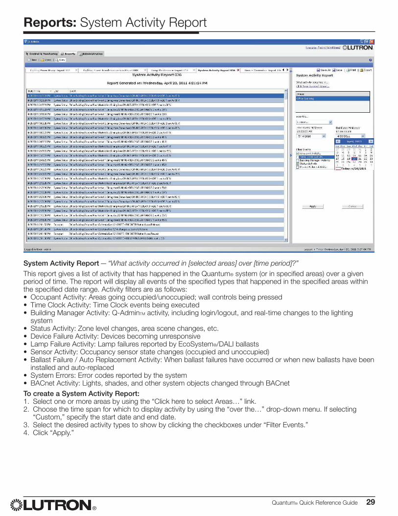
System Activity Report — “What activity occurred in [selected areas] over [time period]?”This report gives a list of activity that has happened in the Quantum® system (or in specified areas) over a given period of time. The report will display all events of the specified types that happened in the specified areas within the specified date range. Activity filters are as follows:• Occupant Activity: Areas going occupied/unoccupied; wall controls being pressed• Time Clock Activity: Time Clock events being executed• Building Manager Activity: Q-AdminTM activity, including login/logout, and real-time changes to the lighting
system• Status Activity: Zone level changes, area scene changes, etc.• Device Failure Activity: Devices becoming unresponsive• Lamp Failure Activity: Lamp failures reported by EcoSystem®/DALI ballasts• Sensor Activity: Occupancy sensor state changes (occupied and unoccupied)• Ballast Failure / Auto Replacement Activity: When ballast failures have occurred or when new ballasts have been
installed and auto-replaced• System Errors: Error codes reported by the system• BACnet Activity: Lights, shades, and other system objects changed through BACnetTo create a System Activity Report:1. Select one or more areas by using the “Click here to select Areas…” link.2. Choose the time span for which to display activity by using the “over the…” drop-down menu. If selecting
“Custom,” specify the start date and end date.3. Select the desired activity types to show by clicking the checkboxes under “Filter Events.”4. Click “Apply.”
30 Quantum® Quick Reference Guide®
Reports: Diagnostics Report
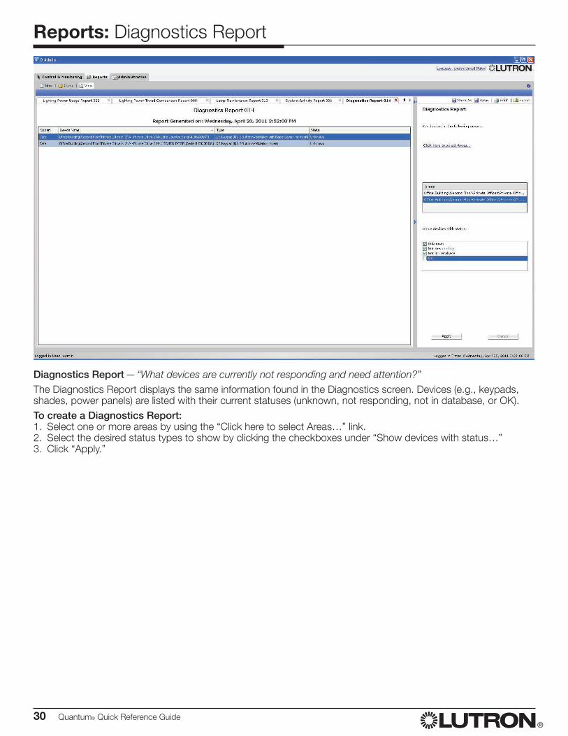
Diagnostics Report — “What devices are currently not responding and need attention?”The Diagnostics Report displays the same information found in the Diagnostics screen. Devices (e.g., keypads, shades, power panels) are listed with their current statuses (unknown, not responding, not in database, or OK).To create a Diagnostics Report:1. Select one or more areas by using the “Click here to select Areas…” link.2. Select the desired status types to show by clicking the checkboxes under “Show devices with status…”3. Click “Apply.”
Quantum® Quick Reference Guide 31®
Reports: Sensor Connection Report
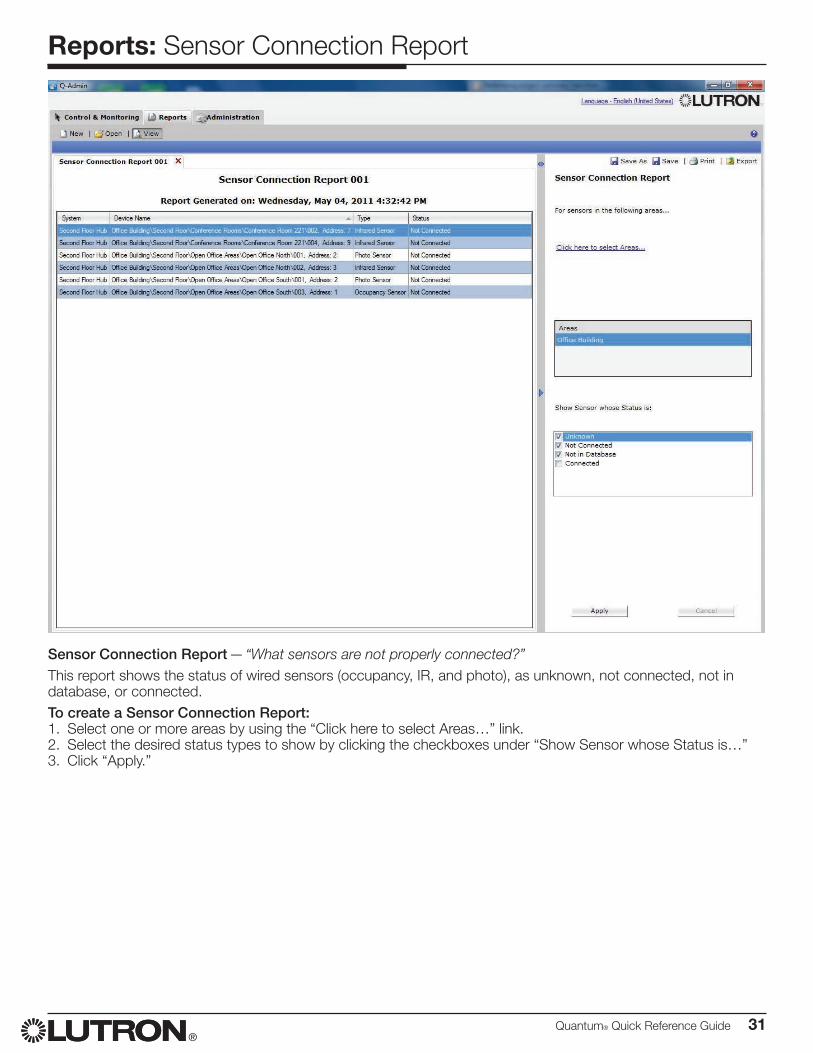
Sensor Connection Report — “What sensors are not properly connected?”This report shows the status of wired sensors (occupancy, IR, and photo), as unknown, not connected, not in database, or connected.To create a Sensor Connection Report:1. Select one or more areas by using the “Click here to select Areas…” link.2. Select the desired status types to show by clicking the checkboxes under “Show Sensor whose Status is…”3. Click “Apply.”
32 Quantum® Quick Reference Guide®
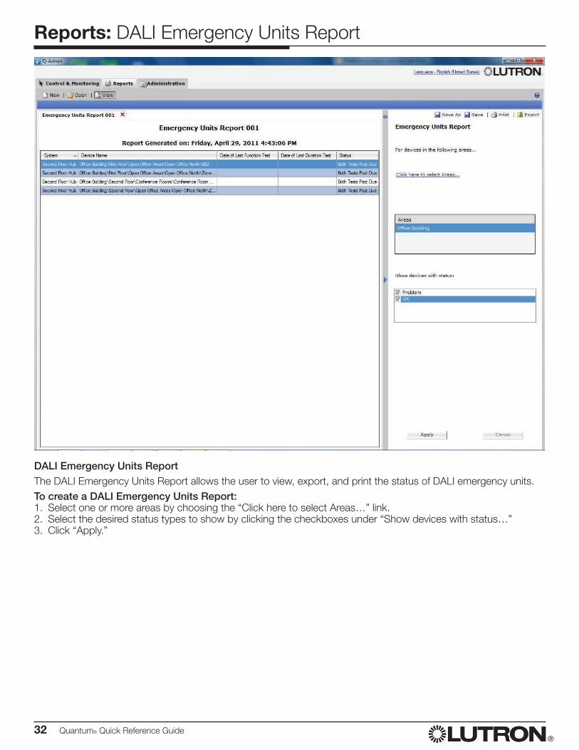
Reports: DALI Emergency Units Report
DALI Emergency Units ReportThe DALI Emergency Units Report allows the user to view, export, and print the status of DALI emergency units.To create a DALI Emergency Units Report:1. Select one or more areas by choosing the “Click here to select Areas…” link.2. Select the desired status types to show by clicking the checkboxes under “Show devices with status…”3. Click “Apply.”
Quantum® Quick Reference Guide 33®
HyperionTM Solar Clock Modification: Overview
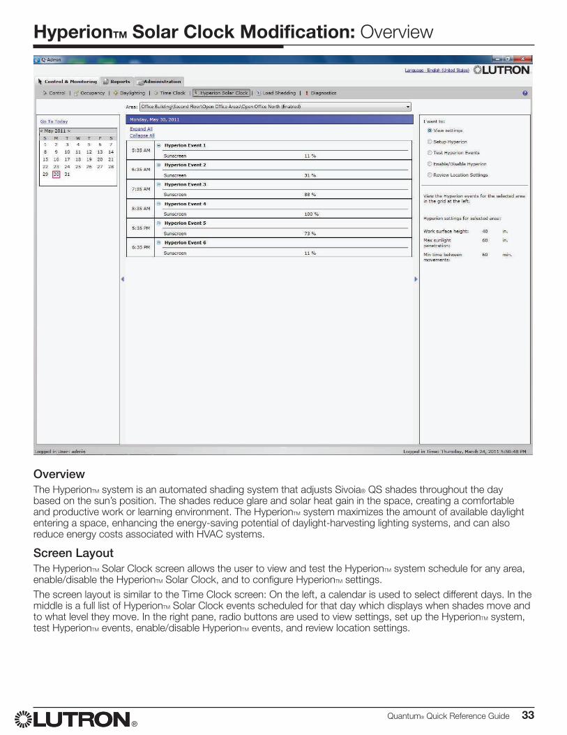
OverviewThe HyperionTM system is an automated shading system that adjusts Sivoia® QS shades throughout the day based on the sun’s position. The shades reduce glare and solar heat gain in the space, creating a comfortable and productive work or learning environment. The HyperionTM system maximizes the amount of available daylight entering a space, enhancing the energy-saving potential of daylight-harvesting lighting systems, and can also reduce energy costs associated with HVAC systems.
Screen LayoutThe HyperionTM Solar Clock screen allows the user to view and test the HyperionTM system schedule for any area, enable/disable the HyperionTM Solar Clock, and to configure HyperionTM settings.The screen layout is similar to the Time Clock screen: On the left, a calendar is used to select different days. In the middle is a full list of HyperionTM Solar Clock events scheduled for that day which displays when shades move and to what level they move. In the right pane, radio buttons are used to view settings, set up the HyperionTM system, test HyperionTM events, enable/disable HyperionTM events, and review location settings.
34 Quantum® Quick Reference Guide®
HyperionTM Solar Clock Modification: Control
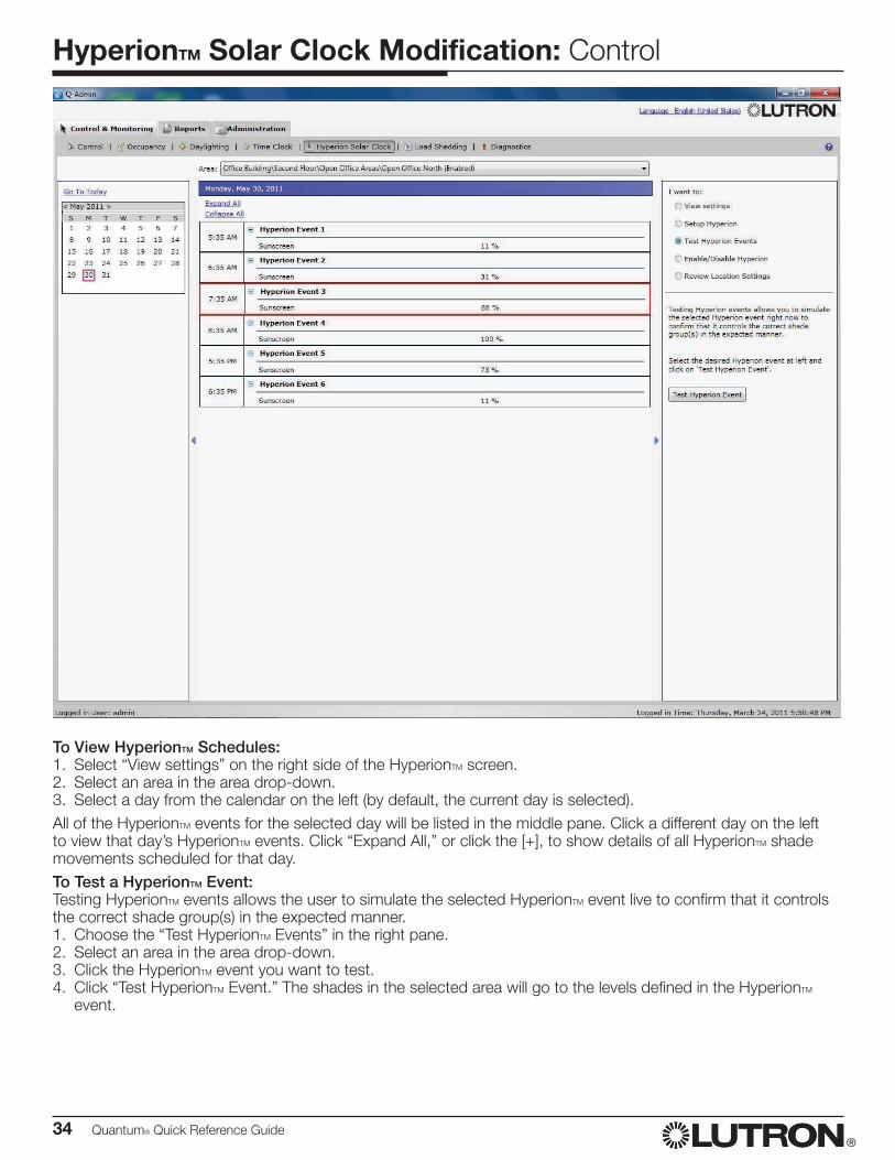
To View HyperionTM Schedules:1. Select “View settings” on the right side of the HyperionTM screen.2. Select an area in the area drop-down.3. Select a day from the calendar on the left (by default, the current day is selected).All of the HyperionTM events for the selected day will be listed in the middle pane. Click a different day on the left to view that day’s HyperionTM events. Click “Expand All,” or click the [+], to show details of all HyperionTM shade movements scheduled for that day.To Test a HyperionTM Event:Testing HyperionTM events allows the user to simulate the selected HyperionTM event live to confirm that it controls the correct shade group(s) in the expected manner.1. Choose the “Test HyperionTM Events” in the right pane.2. Select an area in the area drop-down.3. Click the HyperionTM event you want to test.4. Click “Test HyperionTM Event.” The shades in the selected area will go to the levels defined in the HyperionTM
event.
Quantum® Quick Reference Guide 35®
HyperionTM Solar Clock Modification: Control
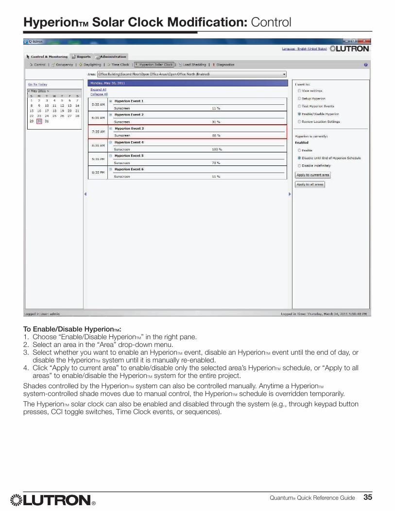
To Enable/Disable HyperionTM:1. Choose “Enable/Disable HyperionTM” in the right pane.2. Select an area in the “Area” drop-down menu.3. Select whether you want to enable an HyperionTM event, disable an HyperionTM event until the end of day, or
disable the HyperionTM system until it is manually re-enabled.4. Click “Apply to current area” to enable/disable only the selected area’s HyperionTM schedule, or “Apply to all
areas” to enable/disable the HyperionTM system for the entire project.Shades controlled by the HyperionTM system can also be controlled manually. Anytime a HyperionTM system-controlled shade moves due to manual control, the HyperionTM schedule is overridden temporarily.The HyperionTM solar clock can also be enabled and disabled through the system (e.g., through keypad button presses, CCI toggle switches, Time Clock events, or sequences).
36 Quantum® Quick Reference Guide®
HyperionTM Solar Clock Modification: Setup
Set Up HyperionTM
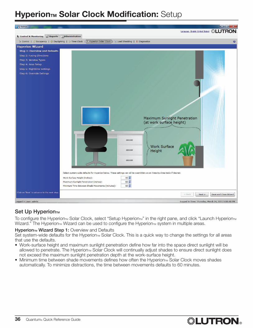
To configure the HyperionTM Solar Clock, select “Setup HyperionTM” in the right pane, and click “Launch HyperionTM Wizard.” The HyperionTM Wizard can be used to configure the HyperionTM system in multiple areas.HyperionTM Wizard Step 1: Overview and DefaultsSet system-wide defaults for the HyperionTM Solar Clock. This is a quick way to change the settings for all areas that use the defaults.• Work-surface height and maximum sunlight penetration define how far into the space direct sunlight will be
allowed to penetrate. The HyperionTM Solar Clock will continually adjust shades to ensure direct sunlight does not exceed the maximum sunlight penetration depth at the work-surface height.
• Minimum time between shade movements defines how often the HyperionTM Solar Clock moves shades automatically. To minimize distractions, the time between movements defaults to 60 minutes.
Quantum® Quick Reference Guide 37®
HyperionTM Solar Clock Modification: Setup
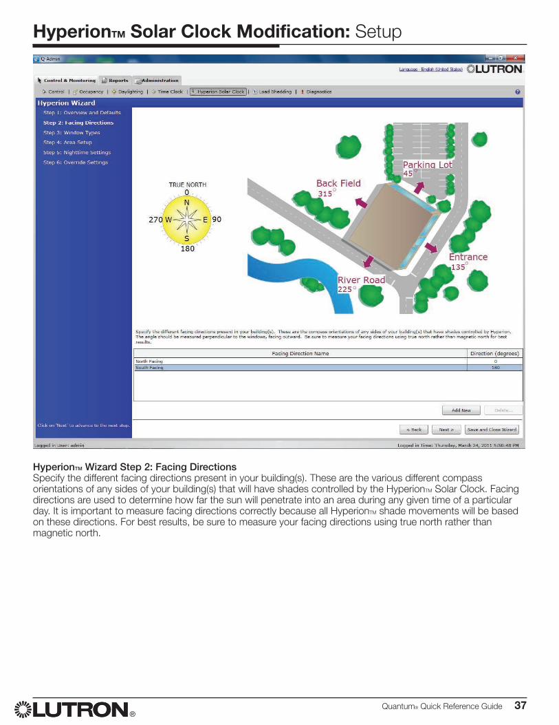
HyperionTM Wizard Step 2: Facing DirectionsSpecify the different facing directions present in your building(s). These are the various different compass orientations of any sides of your building(s) that will have shades controlled by the HyperionTM Solar Clock. Facing directions are used to determine how far the sun will penetrate into an area during any given time of a particular day. It is important to measure facing directions correctly because all HyperionTM shade movements will be based on these directions. For best results, be sure to measure your facing directions using true north rather than magnetic north.
38 Quantum® Quick Reference Guide®
HyperionTM Solar Clock Modification: Setup
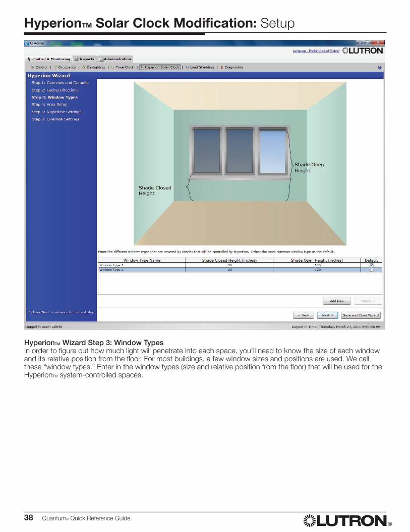
HyperionTM Wizard Step 3: Window TypesIn order to figure out how much light will penetrate into each space, you’ll need to know the size of each window and its relative position from the floor. For most buildings, a few window sizes and positions are used. We call these “window types.” Enter in the window types (size and relative position from the floor) that will be used for the HyperionTM system-controlled spaces.
Quantum® Quick Reference Guide 39®
HyperionTM Solar Clock Modification: Setup
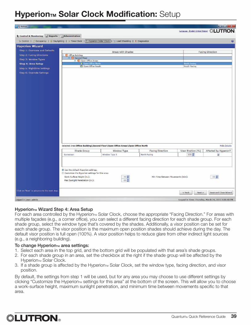
HyperionTM Wizard Step 4: Area SetupFor each area controlled by the HyperionTM Solar Clock, choose the appropriate “Facing Direction.” For areas with multiple façades (e.g., a corner office), you can select a different facing direction for each shade group. For each shade group, select the window type that’s covered by the shades. Additionally, a visor position can be set for each shade group. The visor position is the maximum open position shades should achieve during the day. The default visor position is full open (100%). A visor position helps to reduce glare from other indirect light sources (e.g., a neighboring building).To change HyperionTM area settings:1. Select each area in the top grid, and the bottom grid will be populated with that area’s shade groups.2. For each shade group in an area, set the checkbox at the right if the shade group will be affected by the
HyperionTM Solar Clock.3. If a shade group is affected by the HyperionTM Solar Clock, set the window type, facing direction, and visor
position.By default, the settings from step 1 will be used, but for any area you may choose to use different settings by clicking “Customize the HyperionTM settings for this area” at the bottom of the screen. This will allow you to choose a work-surface height, maximum sunlight penetration, and minimum time between movements specific to that area.
40 Quantum® Quick Reference Guide®
HyperionTM Solar Clock Modification: Setup
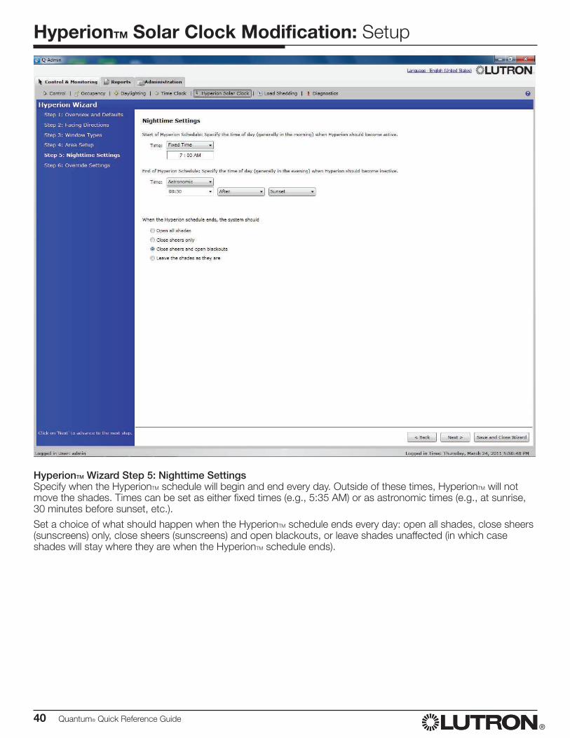
HyperionTM Wizard Step 5: Nighttime SettingsSpecify when the HyperionTM schedule will begin and end every day. Outside of these times, HyperionTM will not move the shades. Times can be set as either fixed times (e.g., 5:35 AM) or as astronomic times (e.g., at sunrise, 30 minutes before sunset, etc.).
Set a choice of what should happen when the HyperionTM schedule ends every day: open all shades, close sheers (sunscreens) only, close sheers (sunscreens) and open blackouts, or leave shades unaffected (in which case shades will stay where they are when the HyperionTM schedule ends).
Quantum® Quick Reference Guide 41®
HyperionTM Solar Clock Modification: Setup
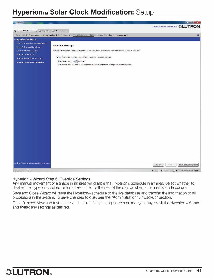
HyperionTM Wizard Step 6: Override SettingsAny manual movement of a shade in an area will disable the HyperionTM schedule in an area. Select whether to disable the HyperionTM schedule for a fixed time, for the rest of the day, or when a manual override occurs.Save and Close Wizard will save the HyperionTM schedule to the live database and transfer the information to all processors in the system. To save changes to disk, see the “Administration” > “Backup” section.Once finished, view and test the new schedule. If any changes are required, you may revisit the HyperionTM Wizard and tweak any settings as desired.
42 Quantum® Quick Reference Guide®
Ballast Replacement
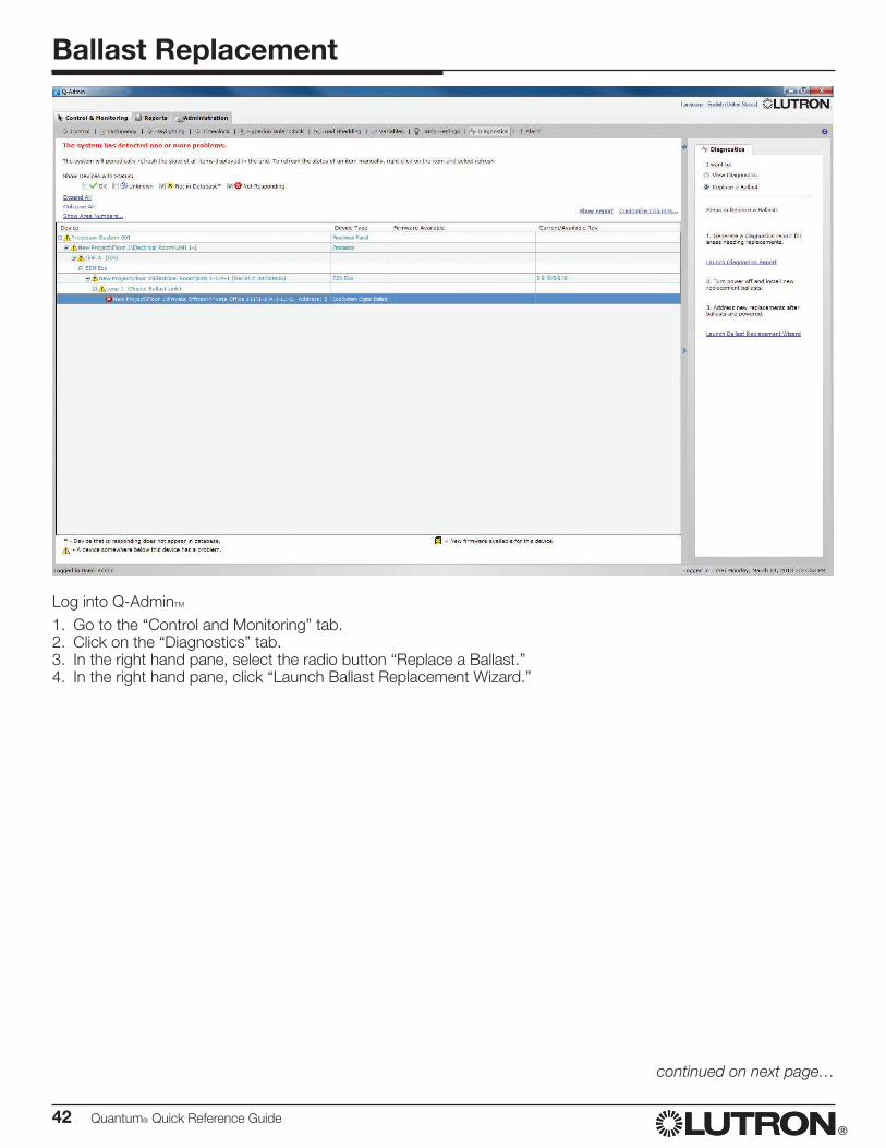
Log into Q-AdminTM
1. Go to the “Control and Monitoring” tab.2. Click on the “Diagnostics” tab.3. In the right hand pane, select the radio button “Replace a Ballast.”4. In the right hand pane, click “Launch Ballast Replacement Wizard.”
continued on next page…
Quantum® Quick Reference Guide 43®
Ballast Replacement
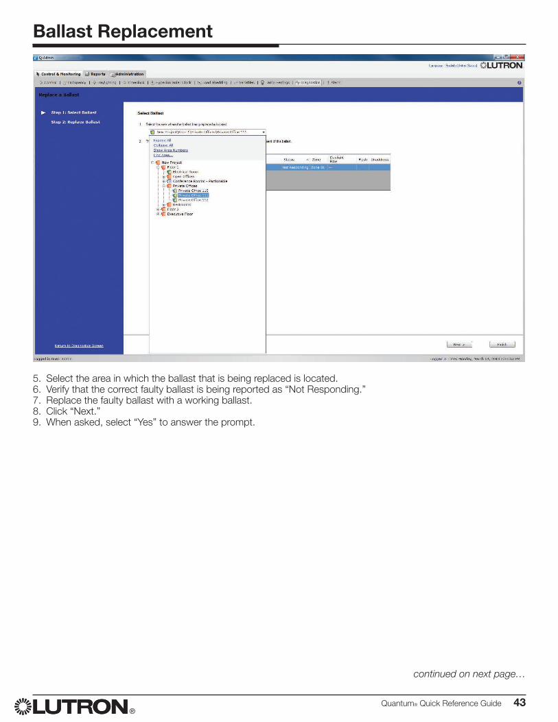
5. Select the area in which the ballast that is being replaced is located.6. Verify that the correct faulty ballast is being reported as “Not Responding.”7. Replace the faulty ballast with a working ballast.8. Click “Next.”9. When asked, select “Yes” to answer the prompt.
continued on next page…
44 Quantum® Quick Reference Guide®
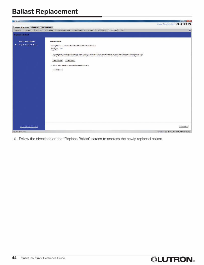
Ballast Replacement
10. Follow the directions on the “Replace Ballast” screen to address the newly-replaced ballast.

Quantum® Quick Reference Guide 45®
Q-DesignTM Software
46 Quantum® Quick Reference Guide®
Area Modification
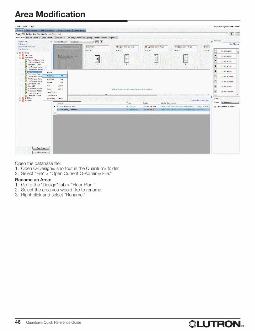
Open the database file:1. Open Q-DesignTM shortcut in the Quantum® folder.2. Select “File” > “Open Current Q-AdminTM File.”Rename an Area:1. Go to the “Design” tab > “Floor Plan.”2. Select the area you would like to rename.3. Right click and select “Rename.”
Quantum® Quick Reference Guide 47®
Control Replacement
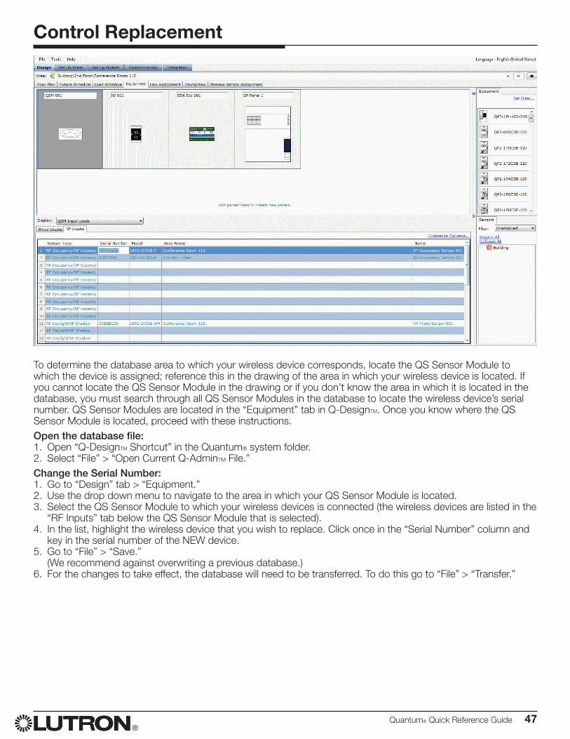
To determine the database area to which your wireless device corresponds, locate the QS Sensor Module to which the device is assigned; reference this in the drawing of the area in which your wireless device is located. If you cannot locate the QS Sensor Module in the drawing or if you don’t know the area in which it is located in the database, you must search through all QS Sensor Modules in the database to locate the wireless device’s serial number. QS Sensor Modules are located in the “Equipment” tab in Q-DesignTM. Once you know where the QS Sensor Module is located, proceed with these instructions.Open the database file:1. Open “Q-DesignTM Shortcut” in the Quantum® system folder.2. Select “File” > “Open Current Q-AdminTM File.”Change the Serial Number:1. Go to “Design” tab > “Equipment.”2. Use the drop down menu to navigate to the area in which your QS Sensor Module is located.3. Select the QS Sensor Module to which your wireless devices is connected (the wireless devices are listed in the
“RF Inputs” tab below the QS Sensor Module that is selected).4. In the list, highlight the wireless device that you wish to replace. Click once in the “Serial Number” column and
key in the serial number of the NEW device.5. Go to “File” > “Save.”
(We recommend against overwriting a previous database.)6. For the changes to take effect, the database will need to be transferred. To do this go to “File” > “Transfer.”

®
Worldwide Technical and Sales AssistanceIf you have questions concerning the installation or operation of this product, call the Lutron® Technical Support Center.Please provide the exact model number when calling. Model number can be found on the product packaging.Example: QSE-IOU.S.A., Canada, and the Caribbean: 1.800.523.9466 Other countries call: +1.610.282.3800 Fax: +1.610.282.1243Visit us on the web at www.lutron.com
Lutron Electronics Co., Inc. 7200 Suter Road
Coopersburg, PA 18036 USA
Lutron, Quantum, EcoSystem, Green Glance, Sivoia, Pico, and ) are registered trademarks and Q-Admin, Hyperion, and Q-Design are trademarks of Lutron Electronics Co. Inc.
Microsoft and Excel are registered trademarks of Microsoft Corporation in the United States and/or other countries.
© 2014 Lutron Electronics Co., Inc.P/N 040398 Rev. A 04/2014


![Quantum Diffie–Hellman Extended to Dynamic Quantum ......smartness [1–3] of healthcare networks, in which the people will get the medical monitoring and treatment in a more quick](https://img.pdfslide.us/doc/110x75/609e07b33df2e50a8002afb2/quantum-diffieahellman-extended-to-dynamic-quantum-smartness-1a3-of.jpg)